US7914561B2 - Resilient bone plate and screw system allowing bi-directional assembly - Google Patents
Resilient bone plate and screw system allowing bi-directional assemblyDownload PDFInfo
- Publication number
- US7914561B2 US7914561B2US10/335,597US33559702AUS7914561B2US 7914561 B2US7914561 B2US 7914561B2US 33559702 AUS33559702 AUS 33559702AUS 7914561 B2US7914561 B2US 7914561B2
- Authority
- US
- United States
- Prior art keywords
- bone
- screw
- bone plate
- plate
- aperture
- Prior art date
- Legal status (The legal status is an assumption and is not a legal conclusion. Google has not performed a legal analysis and makes no representation as to the accuracy of the status listed.)
- Expired - Lifetime, expires
Links
- 210000000988bone and boneAnatomy0.000titleclaimsabstractdescription434
- 238000003780insertionMethods0.000claimsdescription24
- 230000037431insertionEffects0.000claimsdescription24
- 239000000463materialSubstances0.000abstractdescription5
- 230000008602contractionEffects0.000abstractdescription3
- 238000013459approachMethods0.000description32
- 238000000034methodMethods0.000description12
- 230000008901benefitEffects0.000description10
- 238000010276constructionMethods0.000description9
- 238000013519translationMethods0.000description8
- 230000000087stabilizing effectEffects0.000description6
- 230000000295complement effectEffects0.000description4
- 238000001356surgical procedureMethods0.000description4
- 230000006835compressionEffects0.000description3
- 238000007906compressionMethods0.000description3
- 230000000994depressogenic effectEffects0.000description3
- 230000035876healingEffects0.000description3
- 238000002513implantationMethods0.000description3
- 210000003484anatomyAnatomy0.000description2
- 239000012634fragmentSubstances0.000description2
- 239000007943implantSubstances0.000description2
- 239000002184metalSubstances0.000description2
- 229910052751metalInorganic materials0.000description2
- 230000000284resting effectEffects0.000description2
- 206010061246Intervertebral disc degenerationDiseases0.000description1
- 239000000560biocompatible materialSubstances0.000description1
- 230000008468bone growthEffects0.000description1
- 238000012937correctionMethods0.000description1
- 208000018180degenerative disc diseaseDiseases0.000description1
- 230000004927fusionEffects0.000description1
- 230000012010growthEffects0.000description1
- 230000003100immobilizing effectEffects0.000description1
- 208000014674injuryDiseases0.000description1
- 208000021600intervertebral disc degenerative diseaseDiseases0.000description1
- 150000002739metalsChemical class0.000description1
- 238000013508migrationMethods0.000description1
- 230000005012migrationEffects0.000description1
- 238000012986modificationMethods0.000description1
- 230000004048modificationEffects0.000description1
- 230000000399orthopedic effectEffects0.000description1
- 229920000642polymerPolymers0.000description1
- 230000002980postoperative effectEffects0.000description1
- 230000001737promoting effectEffects0.000description1
- 238000011160researchMethods0.000description1
- 210000004872soft tissueAnatomy0.000description1
- 230000008733traumaEffects0.000description1
- 230000004614tumor growthEffects0.000description1
Images


Classifications
- A—HUMAN NECESSITIES
- A61—MEDICAL OR VETERINARY SCIENCE; HYGIENE
- A61B—DIAGNOSIS; SURGERY; IDENTIFICATION
- A61B17/00—Surgical instruments, devices or methods
- A61B17/56—Surgical instruments or methods for treatment of bones or joints; Devices specially adapted therefor
- A61B17/58—Surgical instruments or methods for treatment of bones or joints; Devices specially adapted therefor for osteosynthesis, e.g. bone plates, screws or setting implements
- A61B17/68—Internal fixation devices, including fasteners and spinal fixators, even if a part thereof projects from the skin
- A61B17/80—Cortical plates, i.e. bone plates; Instruments for holding or positioning cortical plates, or for compressing bones attached to cortical plates
- A61B17/8033—Cortical plates, i.e. bone plates; Instruments for holding or positioning cortical plates, or for compressing bones attached to cortical plates having indirect contact with screw heads, or having contact with screw heads maintained with the aid of additional components, e.g. nuts, wedges or head covers
- A61B17/8042—Cortical plates, i.e. bone plates; Instruments for holding or positioning cortical plates, or for compressing bones attached to cortical plates having indirect contact with screw heads, or having contact with screw heads maintained with the aid of additional components, e.g. nuts, wedges or head covers the additional component being a cover over the screw head
- A—HUMAN NECESSITIES
- A61—MEDICAL OR VETERINARY SCIENCE; HYGIENE
- A61B—DIAGNOSIS; SURGERY; IDENTIFICATION
- A61B17/00—Surgical instruments, devices or methods
- A61B17/56—Surgical instruments or methods for treatment of bones or joints; Devices specially adapted therefor
- A61B17/58—Surgical instruments or methods for treatment of bones or joints; Devices specially adapted therefor for osteosynthesis, e.g. bone plates, screws or setting implements
- A61B17/68—Internal fixation devices, including fasteners and spinal fixators, even if a part thereof projects from the skin
- A61B17/80—Cortical plates, i.e. bone plates; Instruments for holding or positioning cortical plates, or for compressing bones attached to cortical plates
- A61B17/8033—Cortical plates, i.e. bone plates; Instruments for holding or positioning cortical plates, or for compressing bones attached to cortical plates having indirect contact with screw heads, or having contact with screw heads maintained with the aid of additional components, e.g. nuts, wedges or head covers
- A61B17/8038—Cortical plates, i.e. bone plates; Instruments for holding or positioning cortical plates, or for compressing bones attached to cortical plates having indirect contact with screw heads, or having contact with screw heads maintained with the aid of additional components, e.g. nuts, wedges or head covers the additional component being inserted in the screw head
- A—HUMAN NECESSITIES
- A61—MEDICAL OR VETERINARY SCIENCE; HYGIENE
- A61B—DIAGNOSIS; SURGERY; IDENTIFICATION
- A61B17/00—Surgical instruments, devices or methods
- A61B17/56—Surgical instruments or methods for treatment of bones or joints; Devices specially adapted therefor
- A61B17/58—Surgical instruments or methods for treatment of bones or joints; Devices specially adapted therefor for osteosynthesis, e.g. bone plates, screws or setting implements
- A61B17/68—Internal fixation devices, including fasteners and spinal fixators, even if a part thereof projects from the skin
- A61B17/80—Cortical plates, i.e. bone plates; Instruments for holding or positioning cortical plates, or for compressing bones attached to cortical plates
- A61B17/8033—Cortical plates, i.e. bone plates; Instruments for holding or positioning cortical plates, or for compressing bones attached to cortical plates having indirect contact with screw heads, or having contact with screw heads maintained with the aid of additional components, e.g. nuts, wedges or head covers
- A61B17/8047—Cortical plates, i.e. bone plates; Instruments for holding or positioning cortical plates, or for compressing bones attached to cortical plates having indirect contact with screw heads, or having contact with screw heads maintained with the aid of additional components, e.g. nuts, wedges or head covers wherein the additional element surrounds the screw head in the plate hole
- A—HUMAN NECESSITIES
- A61—MEDICAL OR VETERINARY SCIENCE; HYGIENE
- A61B—DIAGNOSIS; SURGERY; IDENTIFICATION
- A61B17/00—Surgical instruments, devices or methods
- A61B17/56—Surgical instruments or methods for treatment of bones or joints; Devices specially adapted therefor
- A61B17/58—Surgical instruments or methods for treatment of bones or joints; Devices specially adapted therefor for osteosynthesis, e.g. bone plates, screws or setting implements
- A61B17/68—Internal fixation devices, including fasteners and spinal fixators, even if a part thereof projects from the skin
- A61B17/80—Cortical plates, i.e. bone plates; Instruments for holding or positioning cortical plates, or for compressing bones attached to cortical plates
- A61B17/8085—Cortical plates, i.e. bone plates; Instruments for holding or positioning cortical plates, or for compressing bones attached to cortical plates with pliable or malleable elements or having a mesh-like structure, e.g. small strips
- A—HUMAN NECESSITIES
- A61—MEDICAL OR VETERINARY SCIENCE; HYGIENE
- A61B—DIAGNOSIS; SURGERY; IDENTIFICATION
- A61B17/00—Surgical instruments, devices or methods
- A61B17/56—Surgical instruments or methods for treatment of bones or joints; Devices specially adapted therefor
- A61B17/58—Surgical instruments or methods for treatment of bones or joints; Devices specially adapted therefor for osteosynthesis, e.g. bone plates, screws or setting implements
- A61B17/68—Internal fixation devices, including fasteners and spinal fixators, even if a part thereof projects from the skin
- A61B17/84—Fasteners therefor or fasteners being internal fixation devices
- A61B17/86—Pins or screws or threaded wires; nuts therefor
- A61B17/8685—Pins or screws or threaded wires; nuts therefor comprising multiple separate parts
- A—HUMAN NECESSITIES
- A61—MEDICAL OR VETERINARY SCIENCE; HYGIENE
- A61B—DIAGNOSIS; SURGERY; IDENTIFICATION
- A61B17/00—Surgical instruments, devices or methods
- A61B17/56—Surgical instruments or methods for treatment of bones or joints; Devices specially adapted therefor
- A61B17/58—Surgical instruments or methods for treatment of bones or joints; Devices specially adapted therefor for osteosynthesis, e.g. bone plates, screws or setting implements
- A61B17/68—Internal fixation devices, including fasteners and spinal fixators, even if a part thereof projects from the skin
- A61B17/70—Spinal positioners or stabilisers, e.g. stabilisers comprising fluid filler in an implant
- A61B17/7059—Cortical plates
- A—HUMAN NECESSITIES
- A61—MEDICAL OR VETERINARY SCIENCE; HYGIENE
- A61B—DIAGNOSIS; SURGERY; IDENTIFICATION
- A61B17/00—Surgical instruments, devices or methods
- A61B17/56—Surgical instruments or methods for treatment of bones or joints; Devices specially adapted therefor
- A61B17/58—Surgical instruments or methods for treatment of bones or joints; Devices specially adapted therefor for osteosynthesis, e.g. bone plates, screws or setting implements
- A61B17/88—Osteosynthesis instruments; Methods or means for implanting or extracting internal or external fixation devices
- A61B17/8875—Screwdrivers, spanners or wrenches
Definitions
- the present inventionrelates to bone fixation devices used in orthopedic and spinal surgeries for stabilizing and immobilizing bone fragments. More particularly, this invention relates to a bone plate and screw system that allows both a plate first or anchors first approach to implanting the bone plate.
- Bone fixation devicesare useful for promoting the proper healing of injured or damaged vertebral bone segments caused by trauma, tumor growth, or degenerative disc disease. These external fixation devices immobilize the injured bone segments to ensure the proper growth of new osseous tissue between the damaged segments. External bone fixation devices such as these often include internal bracing and instrumentation to stabilize the spinal column to facilitate the efficient healing of the damaged area without deformity or instability, while minimizing any immobilization and post-operative care of the patient.
- an osteosynthesis platemore commonly referred to as a bone plate
- the fixation plateis a rigid metal or polymeric plate positioned to span bones or bone segments that require immobilization with respect to one another.
- the plateis fastened to the respective bones, using anchors such as bone screws, so that the plate remains in contact with the bones and fixes them in a desired position.
- Anterior cervical platesfor instance, can be useful in providing the mechanical support necessary to keep vertebral bodies in proper position and bridge a weakened or diseased area such as when a disc, vertebral body or spinal fragment has been removed.
- These anterior cervical platesusually include a rigid bone plate having a plurality of screw openings. The openings are either holes or slots that allow for freedom of screw movement.
- the bone plateis placed against the damaged vertebral bodies and bone screws are used to secure the bone plate to the spine, usually with the bone screws being driven into the vertebral bodies.
- bone screws and bone platesallow either a plate first construction or an anchors first construction. That is, some bone screws and bone plates are constructed such that the bone plate is placed onto the intended area to be fixed, and then the bone screws are inserted through the plate to secure the plate to the bone segments. In other bone plate and screw systems, the screws are inserted into the bone segments first, then the plate is secured to the screws.
- One benefit of being able to apply a bone screw and plate system using such an anchors first approachis that the plate is not positioned in a manner that will block the surgeon's view of the implantation site. The surgeon is therefore able to better position the plate and manipulate around the patient's anatomy during implantation.
- One benefit of being able to apply a bone screw and plate system using an anchors first approachis that the plate is not positioned over the surgical site before inserting the screws, and so the plate does not obstruct the surgeon's view when implanting the screws. While it is possible to achieve flexibility and the aforementioned benefits with a two-part bone screw comprising a threaded nut and bone screw or post, a single-component bone screw is more desirable because it does not require intraoperative assembly and therefore has enhanced ease of use.
- the present inventionachieves the aforementioned goals by providing systems of single-component bone screws and bone plates that offer the surgeon the ability to either assemble the screws to the plate, or the plate to the screws, depending on the surgeon's preference and the patient's anatomical conditions.
- the surgeonis given intraoperative flexibility regarding the approach taken when applying the system, allowing the clinician to use either a plate first or anchors first approach with the same screws and plate.
- the bone screws and bone plates of the present inventioninclude a combination of geometric configurations that allow the screws and plates to fit together from different assembly directions. Additionally, the bone screws and bone plates can include material resilience features to allow expansion/contraction during assembly to enable bi-directional attachment one another.
- the various geometric configurations of the present systemallow the bone plate and screws to accommodate different patient anatomies as the natural bones settle after implantation.
- the geometric configurationsalso provide the bone plate and screw system with selective biomechanical properties such as toggling, translation, and/or rotation to facilitate bone growth and healing.
- the bone plate and screw systemcomprises a bone plate for stabilizing bone segments, a screw configured for insertion into bone, and a resilient locking member for securing the bone plate to the screw.
- the bone platehas a first surface and a second, bone-contacting surface that is opposed to the first surface, and an aperture extending through the first and second surfaces.
- the aperturehas a predefined shape and size, and is configured to receive the bone screw.
- the bone screw of the present embodimenthas a head region at a proximal end and an elongated body extending from the head region to a distal end of the screw.
- the head regionis defined by a top flange, a bottom flange, and a groove extending therebetween, while the elongated body includes a threaded portion configured for insertion into bone.
- the aperture of the bone plateincludes a seating groove for capturing the resilient locking member.
- the resilient locking membersecures the bone plate to the implanted screw, and is sized and shaped to mate with the groove of the screw.
- the resilient locking membercan be an expandable snap ring.
- the entire systemcan be assembled together using either a plate first or an anchors first approach, with the latter being desirable for the advantages previously mentioned.
- the entire systemcan be assembled together using both a plate first and an anchors first approach to provide the benefits associated with bi-directional assembly.
- the bone screw of the present systemhas a head region defined by an upper surface, a lower surface, and a sidewall extending therebetween and connecting the upper and lower surfaces.
- the head regionis located at a proximal end, while an elongated body extends from the head region to a distal end of the screw.
- the elongated bodyincludes a threaded portion for insertion into bone.
- a resilient locking memberis provided having a top surface, a bottom surface, and an outer wall extending therebetween and connecting the top and bottom surfaces together.
- the resilient locking memberalso includes a channel extending about its inner circumference, the channel being sized and shaped to capture the head region of the screw. Also, the resilient locking member can have a top surface which extends along a downward slope from an outer edge to an inner edge of the top surface, and a bottom surface which extends along an upward slope from an outer edge to an inner edge of the bottom surface.
- the chamfered featureshelp to facilitate assembly of the bone plate and screw system.
- the bone plate and screw systemcomprises a bone plate for stabilizing bone segments and a resilient screw configured for insertion into bone.
- the bone platehas a first surface and a second, bone-contacting surface that is opposed to the first surface, and an aperture extending through the first and second surfaces.
- the aperturehas a predefined shape and size, and is configured to receive the resilient screw.
- the aperturecan be countersunk on either the first or second surface of the bone plate, or both, to accommodate a direct engagement with the bone screw.
- the resilient screw of the present embodimenthas a head region at a proximal end and an elongated body extending from the head region to a distal end of the screw.
- the elongated bodyincludes a threaded portion for insertion into bone.
- the head regionis defined by a top flange, an bottom flange, and a groove extending therebetween.
- At least one of the top and bottom flanges of the screwis resilient, such that the bone plate and screw system can be assembled together using either a plate first or an anchors first approach, with the latter approach being desirable to provide the benefits associated with an anchors first construction to the system. More preferably, the system can be assembled bi-directionally using both a plate first and an anchors first construction.
- the present systemcan optionally include an attachment member for securing the bone plate to the screw.
- the optional attachment membercan be sized and shaped to mate with the groove of the resilient screw. Further, the attachment member can be configured to be captured within a seating groove provided within the aperture of the bone plate.
- Attachment membercan have a top surface which extends along a downward slope from an outer edge to an inner edge of the top surface, and a bottom surface which extends along an upward slope from an outer edge to an inner edge of the bottom surface. These chamfered surfaces help to facilitate assembly of the bone plate and screw system.
- the resilient bone screw of the present systemhas a head region having a compressible diameter, the head region being defined by an upper surface, a lower surface, and a sidewall extending therebetween and connecting the upper and lower surfaces.
- the head regionis located at a proximal end, while an elongated body extends from the head region to a distal end of the screw.
- the elongated bodyincludes a threaded portion for insertion into bone.
- an optional attachment membercan be provided having a top surface, a bottom surface, and an outer wall extending therebetween and connecting the top and bottom surfaces together.
- the attachment memberalso includes a channel extending about its inner circumference, the channel being sized and shaped to capture the head region of the resilient screw.
- the bone plate and screw systemcomprises a resilient bone plate for stabilizing bone segments, and a screw configured for insertion into bone.
- the bone platehas a body including a first surface and a second, bone-contacting surface that is opposed to the first surface.
- At least one resilient aperture having a predefined shape and sizeextends through the first and second surfaces.
- the apertureis configured to cooperate with a relief slit extending therefrom to allow the aperture to expand and contract to receive the bone screw.
- the relief slitcan extend into a relief hole, or another aperture.
- the resilient bone plate of the present embodimentcan include a plurality of resilient apertures, relief slits and relief holes.
- the bone screw of the present embodimenthas a head region at a proximal end and an elongated body extending from the head region to a distal end of the screw.
- the head regionis defined by a top flange, a bottom flange, and a groove extending therebetween, while the elongated body includes a threaded portion for insertion into bone.
- the bone plate and screw systemcan be assembled together using either a plate first or an anchors first approach, with the latter approach being desirable to provide the benefits accorded with an anchors first approach as previously mentioned.
- the systemcan be assembled bi-directionally using both a plate first and an anchors first construction.
- each of the plurality of aperturescan be shaped like a hole or an oblong slot.
- the aperturesare sized and shaped to receive screws configured to be inserted into bone.
- the screwscan be used to anchor the bone plate to bone segments.
- Each of the screwshas a head region at a proximal end.
- the head regionis defined by a top flange, a bottom flange, and a groove located between the top and bottom flanges and extending about the circumference of the head region.
- the head regionis defined by an upper surface, a lower surface, and a sidewall extending therebetween and connecting the upper and lower surfaces.
- An elongated body which includes a threaded portionextends from the head region to a distal end of the screw.
- the head regionincludes a flange and a groove extending about the circumference of the head region. The body of the screw extends from the groove down to the distal end.
- the bone screws of the present inventioncan be provided with a chamfered proximal surface of the top flange and/or a chamfered distal surface of the bottom flange.
- At least one of the top and bottom flangescan also have a compressible diameter to allow bi-directional attachment to the bone plate.
- the top and bottom flangescan include at least one vertical relief slit extending therethrough.
- at least the top flangeis resilient.
- each screwcan have an open head region, with a threaded bore extending from an upper surface of the head region.
- a threaded capcan be provided that is configured to engage with the threaded bore of the head region.
- the threaded capcan be captured within a nested region of the countersunk rim of the apertures. When threaded onto the head region, the threaded cap provides a smooth profile to the bone plate and screw system while at the same time limiting movement of the screw with respect to the bone plate.
- a plurality of resilient locking membersare provided with the bone plate and screw system of the present invention.
- the resilient locking membersare sized and shaped to mate with the grooves of the screws, and enable locking engagement of the bone plate to the screws.
- Each of the resilient locking membersis configured to be disposed in a seating groove within the apertures of the bone plate.
- the resilient locking memberscan comprise expandable snap rings, or C-rings.
- the seating groove of the bone plateincludes a ratcheted edge along a side thereof.
- a resilient locking membercomprising an expandable snap ring having a notched edge is also provided.
- the ratcheted edge of the seated grooveis configured to mate with the notched edge of the expandable snap ring.
- the expandable snap ringcan further include a channel extending about its inner circumference for capturing the head region of the screw.
- the expandable snap ringcan be configured to nest around the groove of the screw.
- the present inventionalso provides a bone screw which can be assembled to a bone plate in a plate first or anchors first approach.
- the bone screwcomprises a head region at a proximal end of the bone screw.
- the head regionis defined by a top flange, a bottom flange, and a groove extending therebetween about a circumference of the head region.
- An elongated bodyextends from the head region to a distal end of the screw.
- the elongated bodycan include a threaded portion configured for threading into bone.
- the proximal surface of the top flange and the distal surface of the bottom flangecan be chamfered to facilitate the insertion of a locking member over the head region and into the groove.
- At least one of the top and bottom flangeshas a compressible diameter.
- at least one of the top and bottom flangesincludes at least one vertical slot extending through the flange.
- the head regioncan also include a threaded bore extending from a proximal end thereof.
- a tapered postcan be attached to the screw to facilitate alignment and placement of the bone plate over the bone screw. If a resilient locking member is to be used with the system, the locking member should be captured within the seating groove of the bone plate prior to assembly.
- the bone plate(with the optional resilient locking member) is disposed over the tapered post and aligned with the implanted screw. The bone plate is slid down the tapered post and onto the implanted screw. The taper of the post will facilitate the expansion of either the bone plate aperture or the resilient locking member, depending on which system is being used.
- the tapered postcan then be removed from the screw, leaving an assembled bone plate and screw system.
- FIG. 1Ais an exploded view of a bone plate and screw system of the present invention
- FIG. 1Bis a perspective view of the bone screw with the locking member and cap of FIG. 1A ;
- FIG. 1Cis a cutaway view of an aperture of FIG. 1A having a screw, resilient locking member and cap nested therein;
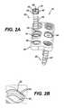
- FIG. 2Ais an exploded view of the bone plate and screw system of FIG. 1A showing a plate first construction
- FIG. 2Bis a detailed view of an aperture of FIG. 2A ;
- FIG. 3illustrates a method of assembling the bone screw and plate system of FIG. 1A ;
- FIG. 4Ais a view of another embodiment of the bone plate and screw system of the present invention.
- FIG. 4Bis a detailed view of an aperture and locking member of FIG. 4A ;
- FIG. 5Aillustrates a step in the method of applying the bone plate and screw system of FIG. 4A ;
- FIG. 5Billustrates another step in the method of applying the bone plate and screw system of FIG. 4A ;
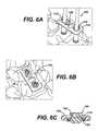
- FIG. 6Aillustrates yet another step in the method of applying the bone plate and screw system of FIG. 4A ;
- FIG. 6Billustrates a completely assembled and implanted bone plate and screw system of FIG. 4A ;
- FIG. 6Cis a cross-sectional view of an aperture of FIG. 6B ;
- FIG. 7Ais a perspective view of another embodiment of a bone screw and resilient locking member of the present invention.
- FIG. 7Bis a side view of the bone screw of FIG. 7A ;
- FIG. 7Cis an enlarged view of the resilient locking member of FIG. 7A ;
- FIG. 8Ais a side view of even another embodiment of a bone screw of the present invention.
- FIG. 8Bis a cross-sectional view of the bone screw of FIG. 8A along with the resilient locking member of FIG. 7C ;
- FIG. 8Cis a cross-sectional view of the bone screw of FIG. 8A ;
- FIG. 9Ais a perspective view of a bone screw for yet another embodiment of a bone plate and screw system of the present invention.
- FIG. 9Bis a bottom-up view of the bone screw of FIG. 9A ;
- FIG. 9Cis a top-down view of the bone screw of FIG. 9A ;
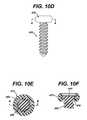
- FIG. 10Ais a perspective view of another embodiment of a bone screw and attachment member of the present invention.
- FIG. 10Bis a perspective view of another embodiment of the bone screw of FIG. 10A ;
- FIG. 10Cis a perspective view of the bone screw of FIG. 10A :
- FIG. 10Dis a side view of the bone screw and locking member of FIG. 10A ;
- FIG. 10Eis a cross-sectional view of the bone screw and locking member of FIG. 10D along lines A-A;
- FIG. 10Fis a cross-sectional view of the bone screw and locking member of FIG. 10E along lines B-B;
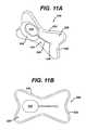
- FIG. 11Ais a perspective view of a bone plate for yet another embodiment of the bone plate and screw system of the present invention.
- FIG. 11Bis a bottom-up view of the bone plate of FIG. 11A ;
- FIG. 11Cshows the bone plate of FIG. 11A with a bone screw
- FIG. 11Dis a perspective view of the bone screw of FIG. 11C ;
- FIG. 11Eis a cross-sectional view of the bone plate and screw of FIG. 11C along lines C-C;
- FIG. 12Ais a perspective view of another embodiment of a bone plate of the present invention.
- FIG. 12Bis a top-down view of the bone plate of FIG. 12A ;
- FIG. 12Cis a top-down view of the bone plate of FIG. 12A with a screw
- FIG. 12Dis a bottom-up view of the bone plate and screw of FIG. 12C ;
- FIG. 12Eis a cross-sectional view of the bone plate and screw of FIG. 12C ;
- FIG. 13Ais a schematic view of another embodiment of a bone plate of the present invention.
- FIG. 13Bis a schematic view of even still another embodiment of a bone plate of the present invention.
- FIG. 14Ais a perspective view of yet another embodiment of a bone plate of the present invention.
- FIG. 14Bis still another perspective view of an embodiment of a bone plate of the present invention.
- the present inventionprovides bone screws and bone plates that offer the surgeon the ability to either assemble the screws to the plate (i.e., plate first approach), or the plate to the screws (i.e., anchors first approach), depending on the surgeon's preference and the patient's anatomical situation.
- the bone screws and bone plates of the present inventioninclude a combination of geometric configurations that allow the screws and plates to fit together from different assembly directions. Additionally, the bone screws and bone plates can include material resilience features to allow expansion/contraction during assembly for enabling bi-directional attachment to one another.
- the system 10includes a bone plate 20 defined by a first surface 22 and a second, bone-contacting surface 24 that is opposed to the first surface 22 .
- the bone plate 20can optionally be convexly curved along its length, enabling the bone plate 20 to conform to the curvature of natural vertebral bones.
- a plurality of apertures 26extend through the first and second surfaces 22 , 24 of the bone plate 20 .
- Each of the apertures 26has a predefined shape and size. For instance, each of the apertures 26 can be shaped like a hole or an elongated, or oblong, slot as illustrated.
- the rim 30 of the apertures 26can be countersunk on the first surface 22 of the bone plate 20 .
- each of the apertures 26is configured to receive one of a plurality of screws 40 configured to be inserted into bone.
- the screws 40can be used to anchor the bone plate 20 to the particular bone segments that require fixation.
- Each of the screws 40has a head region 46 at a proximal end 42 .
- the head region 46is defined by a top flange 48 , a bottom flange 54 , and a groove 60 located between the top and bottom flanges 48 , 54 and extending about the circumference of the head region 46 .
- the top flange 48is defined by an upper surface 50 and a lower surface 52
- the bottom flange 54is defined by an upper surface 56 and a lower surface 58 .
- An elongated body 62which includes a threaded portion 64 extends from the head region 46 to a distal end 44 of the screw 40 .
- each of the locking members 70is resilient and, as illustrated in FIG. 1B , sized and shaped to mate with the groove 60 of the bone screws 40 .
- each of the locking members 70is configured to be disposed in a seating groove 28 within the aperture 26 .
- the seating groove 28lies between the first and second surfaces 22 , 24 and runs about the circumference of the aperture 26 of the bone plate 20 to enable locking engagement of the bone plate 20 to the bone screws 40 .
- the locking memberscan have a top surface that extends along a downward slope from an outer edge to an inner edge of the top surface, and a bottom surface that extends along an upward slope from an outer edge to an inner edge of the bottom surface.
- each of the locking members 70can comprise a C-ring or expandable snap ring for placement around the groove 60 of the bone screws 40 and for capture within the seating groove 28 of the apertures 26 .
- the locking members 70are capable of expanding and contracting to snap into the groove 60 of the bone screws.
- Each of the locking members 70can also include a cutout portion 72 extending around the inner circumference for seating the top flange 48 of the bone screw 40 . As shown in detail in FIG. 1C , the cutout portion 72 enables the top flange 48 of the head portion 46 to sit securely within the locking member 70 , with the lower surface 52 of the top flange 48 resting against the cutout portion 72 .
- the locking member 70can optionally include a cutout portion on its underside (not shown) mirroring the cutout portion 72 on the upper side to accommodate the bottom flange 54 of the bone screw 40 .
- the locking member 70allows for translation in either direction and settling of the screw in to maintain compression across the bone/graft interface.
- top flange 48can include a chamfered upper surface 50 and bottom flange 54 can include a chamfered lower surface 58 .
- the chamfered surfaces 50 , 58 of the bone screw 40help facilitate the placement of the locking member 70 over the head region 46 and into the groove 60 .
- the top flange 48can also include a tool-engaging recess 66 extending vertically therethrough for engaging an insertion tool (not shown).
- each screw 40can optionally have an open head region including a threaded bore 68 extending from an upper surface of the head region 46 .
- the threaded bore 68can be configured as either a hexagonal bore or a threaded bore, for example, to engage an inserter tool such as a post.
- a plurality of threaded caps 80are provided, each of which are rigid and configured to engage with the threaded bore 68 of the head region 46 .
- the threaded cap 80can include a cap head 82 with an elongate, threaded body 84 extending therefrom.
- the threaded body 84is configured to complement and mate with the threaded bore 68 of the bone screw 40 .
- the threaded cap 80can have a tool-engaging bore 86 extending from an upper surface of the cap head 82 for engaging an inserter tool (not shown). As illustrated in FIG. 1C , the tool-engaging bore 86 can comprise a hexagonal bore. It is understood, however, that tool-engaging bore 86 can be configured with any suitable geometry, for example, as a threaded or hexagonal bore.
- the cap head 82has a thickness that matches the depth of the countersunk or depressed rim 30 surrounding the apertures 26 on the first surface 22 of the bone plate 20 . A nested region 32 along the countersunk or depressed rim 30 of the oblong apertures 26 helps capture and stabilize the threaded cap 80 within the aperture 26 .
- the nested region 30has surface features that include notches 34 at discrete locations along the rim 28 .
- the notches 34conform to the outer surface of the threaded cap 80 , which together with the cap 80 allows the screw 40 within the oblong aperture 26 to be fixed at a discrete position. This feature is especially useful in spinal correction procedures where the bone segments to be fixed are selectively compressed or distracted over time, by moving the head region 46 of the screw 40 and its associated cap 80 along the nested region 32 .
- the cap head 82sits flush against first surface 22 of the bone plate 20 to provide a smooth overall profile, avoiding damage to soft tissue surrounding the implant site.
- the present system 10is designed to allow versatile use of the different components, i.e., bone plate, screws, locking ring, cap, etc. in a number of combinations and configurations.
- the bone screws 40can be rigidly (i.e., no toggling, translation or rotation), semi-rigidly (i.e., rotation and toggling but no translation), or dynamically (i.e., translation and optionally rotation) fixed with the system 10 of the present invention.
- the surgeon or clinician using the present inventioncan select and provide for desirable biomechanical properties intraoperatively.
- the ability to control these biomechanical properties with the present system 10is most desirable where the surgeon has to account for the natural settling of bone post-surgery.
- apertures 26are configured to allow relative fixation of the screws 40 .
- the screws 40are able to slide within the oblong aperture 26 until locked into place using the threaded cap 80 which would be captured within the surface features of the countersunk rim 30 , e.g., notches 34 of the nested region 32 around the oblong apertures 26 .
- the threaded cap 80when captured within the notches 34 of the nested region 32 , would thus restrict translation and/or rotation of the screw 40 within the aperture 26 .
- the screw 40 held by the locking member 70 alonewould still be able to translate and rotate, but not toggle.
- FIG. 2Adepicts the bone plate and screw system 10 as applied with a plate first approach.
- the resilient locking members 70are already captured within the seating groove 28 of the apertures 26 of the bone plate 20 prior to assembly.
- the plate 20 with the captured locking members 70is placed on the bone surface to be fixed.
- the bone screws 40are inserted into the bone segments using a conventional bone screw applicator (such as inserter tool 100 as shown in FIG. 3 ) through the captured locking member 70 .
- the bone screws 40can be pre-engaged to the applicator prior to this step.
- the surgeoncan apply force to slide the bottom flange 54 of the screw 40 past the expandable locking member 70 until the head region 46 is nested within the locking member 70 and aperture 26 as shown in FIG. 1C .
- the resilient locking member 70being captured within seating groove 32 of the aperture 26 , thus secures the plate 20 to the bone screw 40 as the bone screw 40 is screwed into the bone segment to be fixed.
- the threaded cap 80can be threaded into the threaded bore 68 of the bone screw 40 to provide rigid fixation of the bone screw 40 to the bone plate 20 .
- the nested region 32 along the countersunk rim 30 of the aperture 26helps stabilize and lock in the threaded cap 80 .
- the nested regionshould complement a portion of the curvature of the outer surface of cap head 82 such that the cap head 82 sits snugly within the depressed or countersunk rim 30 of the elongated aperture 26 .
- the nested region 32 with its surface features, i.e., notches 34helps to avoid any sliding or migration of the bone screw 40 within the elongate slot.
- FIG. 3also depicts an approach for applying the same bone plate and bone screw system 10 of the present invention.
- bone screws 40are first applied to the bone segments to be fixed, using a conventional bone screw insertion tool such as insertion tool 100 which has a threaded tip for engaging the threaded bore 68 of the bone screws 40 .
- a conventional bone screw insertion toolsuch as insertion tool 100 which has a threaded tip for engaging the threaded bore 68 of the bone screws 40 .
- each of the screws 40is already engaged to the insertion tool 100 prior to assembly.
- the insertion tool 100can also include an enlarged tapered head 102 so that the tool 100 can also serve as an expansion post.
- the tool 100can be preassembled with the screw 40 , and the entire tool-screw combination can be placed within a cannulated instrument to be applied all at once.
- the bone screws 40can be inserted into the bone segments to be fixed, and posts attached to their threaded bores 68 afterwards. Once the posts are in place, the bone plate 20 can then be placed over the bone screws 40 , using the posts for aligning the apertures 26 over the implanted bone screws 40 .
- the locking members 70can already be captured within the seating groove 28 of each of the apertures 26 of the plate 20 prior to assembly. After the bone plate 20 is positioned over the implanted bone screw or screws 40 , the plate 20 and the captured locking members 70 are slid down and over the enlarged tapered head 102 .
- the tapered head 102which has a maximum outer diameter larger than the resting inner diameter of the resilient locking member 70 , will facilitate the expansion of the C-ring and enable the resilient locking member 70 to expand and slide over the top flange 48 , then contract and snap back to nest within the groove 60 of the bone screw 40 .
- the resilient locking member 70secures the bone plate 20 to the implanted bone screws 40 .
- the bone screws 40can be completely threaded into the bone segments, if they have not already been done so.
- threaded cap 80can be applied to the threaded bore 68 of the bone screws 40 to further secure the bone plate 20 to the now implanted bone screws 40 .
- the ability of the bone plate and bone screw system 10 to be assembled as either a plate first or anchors first approachprovides the surgeon with the flexibility to assemble the screw to the plate or the plate to the screw, depending on the surgeon's preference and the particular circumstances of the patient.
- the present inventionallows the surgeon more ways to align the bone plate and bone screws during surgery.
- the surgeonis provided with means to adjust the spacing between screws across the graft interface, e.g., to provide and maintain compression across the graft interface to enhance the environment to achieve bony fusion.
- FIG. 4Aillustrates another exemplary bone plate and screw system 110 in accordance with the present invention, in which a bone plate 120 is provided for assembly with bone screws 140 having non-resilient flanges 148 , 154 .
- the bone plate 120can be secured to the bone screws 140 using resilient locking members 170 .
- the bone screws 140 of this embodimentshare similar features to the bone screws 40 of system 10 , while the bone plate 120 shares similar features to the bone plate 20 of system 110 ; thus, similar elements are designated by the same number preceded by the suffix “1.”
- One salient difference between the bone screws 40 of system 10 and the bone screws 140 of system 110is that the top flange 148 of bone screws 140 is not chamfered.
- the bottom flange 154 of the bone screwis chamfered to accommodate a plate-first technique.
- tapered postscan be attached to the bone screws 140 to provide the chamfered surface needed to facilitate the expansion of the resilient locking member 170 over the top flange 148 of the bone screws 140 .
- the resilient locking member 170can include an expandable/compressible C-ring which is configured to sit within the groove 160 of the bone screw 140 .
- the resilient locking member 170is configured to also nest within seating groove 128 of the round aperture 126 of the bone plate 120 .
- a second type of resilient locking member 170 ′is provided for the oblong aperture 126 ′ of the bone plate 120 .
- Resilient locking member 170 ′can also be a split ring for snapping into the groove 160 of the bone screw 140 .
- the resilient locking member 170 ′also has enlarged end portions 174 ′, with at least one of the enlarged end portions 174 ′ including a notched edge 176 ′. As depicted in FIG.
- this notched edge 176 ′is configured to mate and engage with a ratcheted edge 134 running along a portion of the seating groove 128 of the oblong aperture 126 ′.
- the ratcheted edge 134enables the resilient locking member 170 ′ and the bone screw 140 attached therewith to be maintained within the elongated aperture 126 ′ to ratchet in discrete increments with respect to the length of the aperture 126 ′.
- Such featuresprovide the surgeon with even more flexibility with respect to the manner of assembling the bone plate and screw system 110 . These features also provide a clinical benefit to maintain compression at the bone/graft interface.
- the bone plate and screw system 110 of the present inventioncan be assembled using either a plate first or an anchors first approach as described above.
- an anchors first approachwhere the bone plate 120 is assembled to the implanted bone screws 140 , the bone screws 140 are implanted into the bone segments to be fixed.
- FIG. 5Ait is preferable to use a single bone screw 140 per vertebral body 5 to assist with proper alignment of the plate to the screws.
- any number of bone screws 140can be applied as deemed necessary by the surgeon, and as required by the particular bone plate to be used.
- tapered posts 104can be attached to the bone screws 140 as shown in FIG. 5B .
- the tapered posts 104can be pre-engaged to the screws 140 prior to insertion.
- the tapered post 104can extending into a thickened region 106 having a screw-engaging tip for engagement with a tool-engaging bore 168 extending from an upper surface of the top flange 148 of the bone screws 140 .
- the tapered posts 104can be used to align the bone plate 120 , with the resilient locking members 170 , 170 ′ captured within the seated grooves 132 of the bone plate 120 , onto the implanted bone screws 140 , as illustrated in FIG. 6A .
- the thickened region 106 of the posts 104helps facilitate the expansion of the resilient locking members 170 , 170 ′ so that as the resilient locking members 170 , 170 ′ slide down the post 104 , the C-rings gradually expand to slide over the top flanges 148 of the bone screws 140 and snap into their grooves 160 .
- the resilient locking members 170 , 170 ′which are nested within seating grooves 128 of the bone plate, now surround the grooves 160 of the bone screws 140 as depicted in FIG. 6C . After the bone plate 120 is sufficiently secured to the implanted bone screws 140 , the posts can be removed to leave a fully assembled bone plate and screw system 110 as shown in FIG. 6B .
- a bone screw 240 and locking ring 270is provided as shown in FIGS. 7A-7C , for use with a bone plate such as the plate 20 of the system 10 previously described.
- Bone screw 240is sized and shaped to be received within the apertures of the bone plate 20 to anchor the plate 20 to the particular bone segments that require fixation.
- Screw 240has a head region 246 at a proximal end 242 .
- the head region 246is defined by an upper surface 250 , a lower surface 252 , and a sidewall 254 extending therebetween and connecting the upper and lower surfaces 250 , 252 .
- An elongated body 262which includes a threaded portion 264 extends from the head region 246 to a distal end of the screw 240 . As illustrated in FIGS. 7A and 7B , the upper surface 250 and the lower surface 252 of the head region 246 can be chamfered.
- the bone screw 240cooperates with a resilient locking member 270 as shown in FIG. 7A for securing the bone plate 20 to the screw 240 .
- the resilient locking member 270is sized and configured to be captured within the seating groove 28 of the aperture 26 of the bone plate 20 .
- resilient locking member 270can be formed as a C-ring, or an expandable snap ring.
- resilient locking ring 270includes a top surface 280 , a bottom surface 282 , and an outer wall 284 extending therebetween and connecting the top and bottom surfaces, 280 , 282 .
- Top surface 280can be formed so as to extend along a downward slope from an outer edge to an inner edge of the top surface 280 .
- bottom surface 282can be formed so as to extend along an upward slope from an outer edge to an inner edge of the bottom surface. The slopes of the top and bottom surfaces 280 , 282 help to facilitate insertion of the locking member 270 into or onto the head region 246 of the bone screw 240 .
- a channel 286extends about the inner circumference of the locking ring 270 .
- the channel 286is sized and shaped to capture the head region 246 of the screw 240 , and is defined by a top side 290 , a bottom side 292 , and an inner wall 294 connecting the top and bottom sides together.
- the top and bottom sides 290 , 292extend at right angles with respect to the inner wall 294 .
- Such a channel 286provides for some movement of the head region 246 within the channel 286 itself.
- top and bottom sides 290 , 292can be formed at angles with respect to the inner wall 294 , thereby forming a closer fit with the bone screw 240 where the head region 246 includes chamfered surfaces such as is shown in FIG. 7B .
- bone screw 240 ′can include a head region 246 ′ having a sidewall 254 ′ which extends at a perpendicular angle with respect to the upper and lower surfaces 250 ′, 252 ′ as shown in FIG. 8B . As best seen in FIG.
- the head region 246 ′ of the bone screw 240 ′would be complementary in shape and size to the channel 286 of the resilient locking member 270 , enabling both screw 240 ′ and locking member 270 to work and cooperate in congruence together. Additionally, since the interface between the two components is flat, i.e., direct, the overall stability and integrity of the system is enhanced. In both the bone screws 240 , 240 ′ just described, a tool-engaging bore 268 extending from the upper surface 250 , 250 ′ of the screws can be provided, as illustrated in FIG. 8C .
- a bone screw 340is provided having a head region 346 at a proximal end 342 and an elongated body 362 extending from the head region 346 to a distal end 344 of the screw 340 .
- Elongated body 362includes a threaded portion 364 configured for insertion into bone.
- the head region 346has a top flange 348 , a bottom flange 354 , and a groove 360 located between the top and bottom flanges 348 , 354 and extending about the circumference of the head region 346 .
- the top flange 348 of screw 340can include a chamfered upper surface 350 and the bottom flange 354 can include a chamfered lower surface 358 .
- each of the flanges 348 , 354are provided with relief slits 366 extending therethrough, which allow the flanges 348 , 354 to have compressible diameters.
- the slits 366can comprise any suitable shape, including wavy S-shaped slits as shown. While the relief slits 366 of the top flange 348 are illustrated in FIG. 9C as being aligned with respect to the relief slits 366 of the bottom flange 354 , it is contemplated that the relief slits 366 can be offset to provide a more robust system. Though not shown, it is also understood that the screw 340 can include a tool-engaging bore such as with screw 40 .
- bone screw 340can be used to secure a bone plate onto a bone segment to be fixed.
- the bone plateshould be of the type having a first surface, a second, bone-contacting surface opposed to the first surface, and an aperture extending through the first and second surfaces.
- the apertureshould be sufficiently sized and shaped to receive the screw 340 and nest within the groove 360 between the two flanges 348 , 354 .
- the resiliency of the flanges 348 , 354enables bone screw 340 to be secured to a bone plate without the need for a locking member in both a plate first or an anchors first approach.
- the screw 340can be inserted into a bone segment to be fixed in an anchors first approach.
- at least the top flange of the bone screwshould be resilient.
- the aperture of the bone platecan be placed over a post attached to the screw 340 to align the bone plate to the implanted screw 340 .
- the optional postcan be attached to the screw 340 prior to or after insertion into the bone segment to assist with alignment of the screw to the aperture of the plate.
- the bone plateis slid down the post and onto the screw.
- the flexibility of the top flange 348enables the aperture to move over the flange 348 and nest within the groove 360 of the screw 340 .
- the present systemcan also utilize an optional attachment member and a bone plate having a seating groove such as bone plate 20 described above.
- the attachment memberhelps to facilitate the engagement and cooperation of the bone screw 340 and the bone plate.
- the attachment membershould be configured to nest within the seating groove 28 of the bone plate 20 and seat around the groove 360 of the screw 340 .
- the attachment memberwould be captured within the seating groove 28 of the bone plate 20 prior to assembly so that the step of securing the aperture 26 around the screw 340 would include securing the captured attachment member around the groove 360 of the bone screw 340 .
- the attachment membercan include a notched edge such as with locking member 170 ′.
- the seating groove of the bone platecan also include a ratcheted edge along its side to allow the notched edge of the attachment member to mate and incrementally move within the aperture itself.
- a threaded cap 80can be attached to the bone screw 340 to limit movement of the screw 340 within the aperture 26 in the same manner described above.
- FIGS. 10A-10Fillustrate yet another embodiment of a bone screw 440 and locking member 470 of the present invention.
- Bone screw 440includes a head region 446 at a proximal end 442 and an elongated body 462 extending from the head region 446 to a distal end 444 of the screw 440 .
- the elongated body 462includes a threaded portion 464 configured for insertion into bone.
- the head region 446includes an upper surface 450 , a lower surface 452 , and a sidewall 454 extending therebetween and connecting the upper and lower surfaces 450 , 452 . As illustrated in FIG.
- the sidewall 454can extend at a perpendicular angle with respect to the upper and lower surfaces 450 , 452 .
- FIG. 10Bshows a similar bone screw 440 ′ where the upper and lower surfaces 450 , 452 are chamfered.
- Both screws 440 , 440 ′are provided with relief slits 466 , 466 ′ that extend through the head region 446 to provide it with a compressible diameter.
- the slits 466can comprise any suitable shape, including wavy S-shaped slits as shown. While it is not shown, it is understood that these bone screws 440 , 440 ′ can be provided with a tool-engaging recess and/or tool-engaging bore for attaching an insertion tool thereto.
- Bone screw 440can be used to secure a bone plate onto a bone segment to be fixed.
- the bone plateshould be of the type having a first surface, a second, bone-contacting surface opposed to the first surface, and an aperture extending through the first and second surfaces.
- the apertureshould be sufficiently sized and shaped to receive the screw 440 and also include a seating groove to capture the head region 446 of the screw 440 .
- the aperture of the bone plateshould be countersunk on at least one of the first and second surfaces to accommodate and facilitate the engagement of the screw with the bone plate.
- the resiliency of the head region 446enables bone screw 440 to be secured to a bone plate without the need for a locking member in both a plate first or an anchors first approach.
- the screw 440can be inserted into a bone segment to be fixed in an anchors first approach.
- the aperture of the bone platecan be placed over a post attached to the screw 440 to align the bone plate to the implanted screw 440 .
- the postcan be attached to the screw 440 prior to or after insertion into the bone segment.
- the bone plateis slid down the post and onto the screw 440 .
- the compressibility of the head region 446enables the aperture to move over the head region 446 . Once the head region 446 is captured within the seating groove of the bone plate, the post can be removed from the screw.
- the bone screw 440can be used in combination with an optional attachment member 470 .
- the attachment member 470helps to facilitate the engagement and cooperation of the bone screw 440 and the bone plate.
- the attachment member 470is similar to the locking member 270 shown in FIG. 7C but is a closed ring rather than a C-ring.
- the attachment member 470can be captured within the seating groove of the bone plate prior to assembly so that placement of the aperture over the post also aligns the captured attachment member with the implanted screw 440 . Once the attachment member 470 is moved down and over the resilient head region 446 , the head region 446 can nest within the groove of the attachment member 470 , as shown in FIGS. 10E and 10F .
- the congruency and integrity of the interference fitis maintained.
- a threaded capcan be attached to the screw to limit its movement within the aperture.
- the present inventionalso provides a bone plate and screw system in which the plate itself is resilient.
- bone plate 520has a resilient aperture 528 for use with a non-resilient bone screw for stabilizing bone segments to be fixed.
- the bone plate 520includes a body 522 defined by a first surface 524 , a second, bone-contacting surface 526 opposed to the first surface 524 , and a resilient aperture 528 extending through the first and second surfaces 524 , 526 whose material resilience enables bi-directional assembly of a bone screw and the bone plate 520 .
- the aperture 528is sized and configured to receive a bone screw such as exemplary bone screw 502 as shown in FIGS. 11C-11E . As illustrated in detail in FIG.
- bone screw 502includes a proximal end 504 , a distal end 506 , a head region 512 defined by a flange 514 , a groove 516 extending about the circumference of the head region 512 , and a body 508 extend from the groove 516 .
- the body 508includes a threaded portion 510 configured for insertion into bone.
- the aperture 528can be countersunk from a first surface 524 of the bone plate.
- the countersunk portion 534 of the aperture 528can extend toward the second, bone-contacting surface 526 of the bone plate 520 .
- the groove 516 of bone screw 502is configured to mate with the aperture 528 of the resilient bone plate 520 , while the flange 514 is configured to seat against the countersunk region 534 of the aperture 528 .
- a relief slit 538is provided.
- the relief slit 538extends through the first and second surfaces 524 , 526 of the plate 520 , and extends from the aperture 528 to a through-hole, or relief hole 540 .
- the relief slit 538 and relief hole 540provide the aperture 528 with the ability to expand and contract.
- the slit 538can extend longitudinally through the bone plate 520 .
- Plate 520can be concavely curved along its longitudinal axis to provide a better fit with the natural contours of human bones.
- the body 522can be defined by a pair of longitudinal sidewalls 530 connected by a pair of opposed lateral endwalls 532 .
- a midsection of each of the longitudinal sidewallsextends 530 towards a central region of the body 522 .
- a midsection of each of the lateral endwalls 532extends towards a central region of the body 522 .
- the aperture 528can be configured as either a slot (as shown) to allow translation of the screw, or as a hole to provide a rigid fixed position for the screw within the plate.
- FIGS. 12A and 12Billustrate another variation of the resilient bone plate of the present invention, in which the aperture 528 ′ of bone plate 520 ′ can also include a countersunk portion 536 ′ from the second surface 526 ′ of the plate 520 ′.
- the bone plate 520 ′ shownis similar to the bone plate 520 previously described, with common features designated by the same numeral followed by the symbol “′.”
- the resilient bone plate 520 ′ of the present inventioncan be applied using a bone screw similar to the one illustrated in FIGS. 1A-1C , and described above as bone screw 40 .
- FIGS. 12C-12Eillustrate the bone plate 520 ′ assembled with an exemplary bone screw 40 .
- the aperture 528 ′is sized and shaped to directly engage the groove 60 of the bone screw 40 for locking engagement.
- the flexibility of the aperture 528 ′enables the bone plate 520 ′ to be assembled to bone screw 40 in either a plate first or an anchors first approach.
- the bone screw 40can be inserted into the bone segment to be fixed.
- the aperture 528can be placed onto the post and slid down.
- the postcan be attached either prior to or after insertion of the screw 40 into the bone segment.
- the postcan be tapered.
- the taper of the postopens up the resilient aperture 528 ′, allowing the aperture 528 ′ to move over the top flange 48 and snap into the groove 60 of the bone screw 40 as shown in FIG. 12E .
- the postcan be removed.
- the countersunk portion 534 ′can also include a nesting region similar to the one for bone plate 20 . If desired, a threaded cap can be attached to the screw 40 to restrict movement of the screw 40 within the aperture 528 ′.
- the resilient bone plate 520 of the present inventioncan be provided with a seating groove around the aperture 528 .
- Such a featurewould enable the bone plate 520 to be used with a bone screw having a single flange, similar to the bone screw 240 ′ illustrated in FIG. 8A .
- a locking membersuch as locking member 270 can be used with bone screw 240 ′ to secure the bone plate 520 to the implanted bone screw.
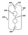
- FIGS. 13A and 13Billustrate yet more configurations for the resilient bone plate of the present invention, in which the resilient bone plate comprises a plurality of apertures, relief slits, and relief holes.
- bone plate 620can be defined by a pair of longitudinal sidewalls 630 connected by a pair of opposed lateral endwalls 632 .
- the bone plate 620can include a plurality of apertures 628 connected together by a relief slit 638 which terminates into a pair of relief holes 640 as shown in FIG. 13A .
- An alternative patternis shown in FIG. 13B , in which bone plate 620 ′ can include a pair of longitudinal sidewalls 630 ′ connected by a pair of opposed lateral endwalls 632 ′.
- Bone plate 620 ′includes a pair of relief slits 638 ′, each relief slit 638 ′ extending into at least one relief hole 640 ′ and an aperture 628 ′.
- FIGS. 14A and 14BYet more configurations are illustrated in FIGS. 14A and 14B , in which a resilient bone plate 720 and a resilient bone plate 820 are shown.
- Resilient bone plate 720includes a pair of lateral sidewalls 730 connected by a pair of opposed lateral endwalls 732 .
- Relief slits 738extend along the lateral endwalls 732 , each relief slit 738 terminating at each end into an aperture 728 .
- resilient bone plate 820includes a single relief slit 538 extending into apertures 828 at each terminal end.
- the aperturecan be configured as either a slot to allow translation of the screw, or as a hole to provide a rigid fixed position for the screw within the plate.
- resilient bone plate 820includes apertures 828 having both shapes.
- All of the bone plate and screw systems of the present inventioncan be assembled together using either a plate first or an anchors first approach, with the latter approach being desirable to provide the benefits accorded with an anchors first approach as previously mentioned.
- the systemcan be assembled bi-directionally using both a plate first and an anchors first construction.
- the components of the systems of the present inventioncan be formed from any biocompatible material, including biocompatible metals and polymers. It is also contemplated that the components can equally comprise bioabsorbable and/or biodegradable materials. Likewise, all components are considered to require dimensions suitable for use as medical implants.
Landscapes
- Health & Medical Sciences (AREA)
- Orthopedic Medicine & Surgery (AREA)
- Surgery (AREA)
- Life Sciences & Earth Sciences (AREA)
- Heart & Thoracic Surgery (AREA)
- Nuclear Medicine, Radiotherapy & Molecular Imaging (AREA)
- Engineering & Computer Science (AREA)
- Biomedical Technology (AREA)
- Neurology (AREA)
- Medical Informatics (AREA)
- Molecular Biology (AREA)
- Animal Behavior & Ethology (AREA)
- General Health & Medical Sciences (AREA)
- Public Health (AREA)
- Veterinary Medicine (AREA)
- Surgical Instruments (AREA)
Abstract
Description
Not applicable.
Not Applicable.
The present invention relates to bone fixation devices used in orthopedic and spinal surgeries for stabilizing and immobilizing bone fragments. More particularly, this invention relates to a bone plate and screw system that allows both a plate first or anchors first approach to implanting the bone plate.
Bone fixation devices are useful for promoting the proper healing of injured or damaged vertebral bone segments caused by trauma, tumor growth, or degenerative disc disease. These external fixation devices immobilize the injured bone segments to ensure the proper growth of new osseous tissue between the damaged segments. External bone fixation devices such as these often include internal bracing and instrumentation to stabilize the spinal column to facilitate the efficient healing of the damaged area without deformity or instability, while minimizing any immobilization and post-operative care of the patient.
One type of external bone fixation device is an osteosynthesis plate, more commonly referred to as a bone plate, that can be used to immobilize adjacent skeletal parts such as vertebral bones. Typically, the fixation plate is a rigid metal or polymeric plate positioned to span bones or bone segments that require immobilization with respect to one another. The plate is fastened to the respective bones, using anchors such as bone screws, so that the plate remains in contact with the bones and fixes them in a desired position. Anterior cervical plates, for instance, can be useful in providing the mechanical support necessary to keep vertebral bodies in proper position and bridge a weakened or diseased area such as when a disc, vertebral body or spinal fragment has been removed. These anterior cervical plates usually include a rigid bone plate having a plurality of screw openings. The openings are either holes or slots that allow for freedom of screw movement. The bone plate is placed against the damaged vertebral bodies and bone screws are used to secure the bone plate to the spine, usually with the bone screws being driven into the vertebral bodies.
Currently, bone screws and bone plates allow either a plate first construction or an anchors first construction. That is, some bone screws and bone plates are constructed such that the bone plate is placed onto the intended area to be fixed, and then the bone screws are inserted through the plate to secure the plate to the bone segments. In other bone plate and screw systems, the screws are inserted into the bone segments first, then the plate is secured to the screws. One benefit of being able to apply a bone screw and plate system using such an anchors first approach is that the plate is not positioned in a manner that will block the surgeon's view of the implantation site. The surgeon is therefore able to better position the plate and manipulate around the patient's anatomy during implantation.
It would be desirable to provide bone screws and bone plate systems that are both easy to use and capable of bi-directional assembly using either a plate first or anchors first construction. Such a system would allow the clinician the flexibility to use either a plate first or an anchors first approach with the same bone screw and bone plate during surgery. One benefit of being able to apply a bone screw and plate system using an anchors first approach is that the plate is not positioned over the surgical site before inserting the screws, and so the plate does not obstruct the surgeon's view when implanting the screws. While it is possible to achieve flexibility and the aforementioned benefits with a two-part bone screw comprising a threaded nut and bone screw or post, a single-component bone screw is more desirable because it does not require intraoperative assembly and therefore has enhanced ease of use.
The present invention achieves the aforementioned goals by providing systems of single-component bone screws and bone plates that offer the surgeon the ability to either assemble the screws to the plate, or the plate to the screws, depending on the surgeon's preference and the patient's anatomical conditions. With this invention, the surgeon is given intraoperative flexibility regarding the approach taken when applying the system, allowing the clinician to use either a plate first or anchors first approach with the same screws and plate. The bone screws and bone plates of the present invention include a combination of geometric configurations that allow the screws and plates to fit together from different assembly directions. Additionally, the bone screws and bone plates can include material resilience features to allow expansion/contraction during assembly to enable bi-directional attachment one another. The various geometric configurations of the present system allow the bone plate and screws to accommodate different patient anatomies as the natural bones settle after implantation. The geometric configurations also provide the bone plate and screw system with selective biomechanical properties such as toggling, translation, and/or rotation to facilitate bone growth and healing.
In one exemplary system of the present invention, the bone plate and screw system comprises a bone plate for stabilizing bone segments, a screw configured for insertion into bone, and a resilient locking member for securing the bone plate to the screw. The bone plate has a first surface and a second, bone-contacting surface that is opposed to the first surface, and an aperture extending through the first and second surfaces. The aperture has a predefined shape and size, and is configured to receive the bone screw.
The bone screw of the present embodiment has a head region at a proximal end and an elongated body extending from the head region to a distal end of the screw. In one aspect of the invention, the head region is defined by a top flange, a bottom flange, and a groove extending therebetween, while the elongated body includes a threaded portion configured for insertion into bone. Additionally, the aperture of the bone plate includes a seating groove for capturing the resilient locking member.
The resilient locking member secures the bone plate to the implanted screw, and is sized and shaped to mate with the groove of the screw. For example, the resilient locking member can be an expandable snap ring. The entire system can be assembled together using either a plate first or an anchors first approach, with the latter being desirable for the advantages previously mentioned. Preferably, the entire system can be assembled together using both a plate first and an anchors first approach to provide the benefits associated with bi-directional assembly.
In another aspect of the invention, the bone screw of the present system has a head region defined by an upper surface, a lower surface, and a sidewall extending therebetween and connecting the upper and lower surfaces. The head region is located at a proximal end, while an elongated body extends from the head region to a distal end of the screw. The elongated body includes a threaded portion for insertion into bone. To secure the bone plate to the screw, a resilient locking member is provided having a top surface, a bottom surface, and an outer wall extending therebetween and connecting the top and bottom surfaces together.
The resilient locking member also includes a channel extending about its inner circumference, the channel being sized and shaped to capture the head region of the screw. Also, the resilient locking member can have a top surface which extends along a downward slope from an outer edge to an inner edge of the top surface, and a bottom surface which extends along an upward slope from an outer edge to an inner edge of the bottom surface. The chamfered features help to facilitate assembly of the bone plate and screw system.
In another exemplary system of the present invention, the bone plate and screw system comprises a bone plate for stabilizing bone segments and a resilient screw configured for insertion into bone. The bone plate has a first surface and a second, bone-contacting surface that is opposed to the first surface, and an aperture extending through the first and second surfaces. The aperture has a predefined shape and size, and is configured to receive the resilient screw. The aperture can be countersunk on either the first or second surface of the bone plate, or both, to accommodate a direct engagement with the bone screw.
The resilient screw of the present embodiment has a head region at a proximal end and an elongated body extending from the head region to a distal end of the screw. The elongated body includes a threaded portion for insertion into bone. In one aspect of the invention, the head region is defined by a top flange, an bottom flange, and a groove extending therebetween. At least one of the top and bottom flanges of the screw is resilient, such that the bone plate and screw system can be assembled together using either a plate first or an anchors first approach, with the latter approach being desirable to provide the benefits associated with an anchors first construction to the system. More preferably, the system can be assembled bi-directionally using both a plate first and an anchors first construction.
The present system can optionally include an attachment member for securing the bone plate to the screw. The optional attachment member can be sized and shaped to mate with the groove of the resilient screw. Further, the attachment member can be configured to be captured within a seating groove provided within the aperture of the bone plate. Attachment member can have a top surface which extends along a downward slope from an outer edge to an inner edge of the top surface, and a bottom surface which extends along an upward slope from an outer edge to an inner edge of the bottom surface. These chamfered surfaces help to facilitate assembly of the bone plate and screw system.
In another aspect of the invention, the resilient bone screw of the present system has a head region having a compressible diameter, the head region being defined by an upper surface, a lower surface, and a sidewall extending therebetween and connecting the upper and lower surfaces. The head region is located at a proximal end, while an elongated body extends from the head region to a distal end of the screw. The elongated body includes a threaded portion for insertion into bone. To secure the bone plate to the resilient screw, an optional attachment member can be provided having a top surface, a bottom surface, and an outer wall extending therebetween and connecting the top and bottom surfaces together. The attachment member also includes a channel extending about its inner circumference, the channel being sized and shaped to capture the head region of the resilient screw.
In yet another exemplary system of the present invention, the bone plate and screw system comprises a resilient bone plate for stabilizing bone segments, and a screw configured for insertion into bone. The bone plate has a body including a first surface and a second, bone-contacting surface that is opposed to the first surface. At least one resilient aperture having a predefined shape and size extends through the first and second surfaces. The aperture is configured to cooperate with a relief slit extending therefrom to allow the aperture to expand and contract to receive the bone screw. The relief slit can extend into a relief hole, or another aperture. The resilient bone plate of the present embodiment can include a plurality of resilient apertures, relief slits and relief holes.
The bone screw of the present embodiment has a head region at a proximal end and an elongated body extending from the head region to a distal end of the screw. In one aspect of the invention, the head region is defined by a top flange, a bottom flange, and a groove extending therebetween, while the elongated body includes a threaded portion for insertion into bone. The bone plate and screw system can be assembled together using either a plate first or an anchors first approach, with the latter approach being desirable to provide the benefits accorded with an anchors first approach as previously mentioned. Preferably, the system can be assembled bi-directionally using both a plate first and an anchors first construction.
In other features of the present invention, each of the plurality of apertures can be shaped like a hole or an oblong slot. The apertures are sized and shaped to receive screws configured to be inserted into bone. The screws can be used to anchor the bone plate to bone segments. Each of the screws has a head region at a proximal end. In one instance, the head region is defined by a top flange, a bottom flange, and a groove located between the top and bottom flanges and extending about the circumference of the head region. In another instance, the head region is defined by an upper surface, a lower surface, and a sidewall extending therebetween and connecting the upper and lower surfaces. An elongated body which includes a threaded portion extends from the head region to a distal end of the screw. In yet another instance, the head region includes a flange and a groove extending about the circumference of the head region. The body of the screw extends from the groove down to the distal end.
The bone screws of the present invention can be provided with a chamfered proximal surface of the top flange and/or a chamfered distal surface of the bottom flange. At least one of the top and bottom flanges can also have a compressible diameter to allow bi-directional attachment to the bone plate. For instance, the top and bottom flanges can include at least one vertical relief slit extending therethrough. To allow for anchors first construction in this embodiment, at least the top flange is resilient. Further, each screw can have an open head region, with a threaded bore extending from an upper surface of the head region. A threaded cap can be provided that is configured to engage with the threaded bore of the head region. The threaded cap can be captured within a nested region of the countersunk rim of the apertures. When threaded onto the head region, the threaded cap provides a smooth profile to the bone plate and screw system while at the same time limiting movement of the screw with respect to the bone plate.
To secure the bone plate to the screws, a plurality of resilient locking members are provided with the bone plate and screw system of the present invention. The resilient locking members are sized and shaped to mate with the grooves of the screws, and enable locking engagement of the bone plate to the screws. Each of the resilient locking members is configured to be disposed in a seating groove within the apertures of the bone plate. The resilient locking members can comprise expandable snap rings, or C-rings.
In one exemplary embodiment of the present invention, the seating groove of the bone plate includes a ratcheted edge along a side thereof. A resilient locking member comprising an expandable snap ring having a notched edge is also provided. The ratcheted edge of the seated groove is configured to mate with the notched edge of the expandable snap ring. The expandable snap ring can further include a channel extending about its inner circumference for capturing the head region of the screw. Alternatively, the expandable snap ring can be configured to nest around the groove of the screw. Such features provide the clinician with even more flexibility with respect to the manner of implementation.
The present invention also provides a bone screw which can be assembled to a bone plate in a plate first or anchors first approach. The bone screw comprises a head region at a proximal end of the bone screw. The head region is defined by a top flange, a bottom flange, and a groove extending therebetween about a circumference of the head region. An elongated body extends from the head region to a distal end of the screw. The elongated body can include a threaded portion configured for threading into bone. The proximal surface of the top flange and the distal surface of the bottom flange can be chamfered to facilitate the insertion of a locking member over the head region and into the groove. Preferably, at least one of the top and bottom flanges has a compressible diameter. Further, at least one of the top and bottom flanges includes at least one vertical slot extending through the flange. The head region can also include a threaded bore extending from a proximal end thereof.
Also provided is a method for assembling the bone plate and screw systems described above using an anchors first approach, wherein at least one screw is inserted into a bone segment to be fixed. A tapered post can be attached to the screw to facilitate alignment and placement of the bone plate over the bone screw. If a resilient locking member is to be used with the system, the locking member should be captured within the seating groove of the bone plate prior to assembly. Next, the bone plate (with the optional resilient locking member) is disposed over the tapered post and aligned with the implanted screw. The bone plate is slid down the tapered post and onto the implanted screw. The taper of the post will facilitate the expansion of either the bone plate aperture or the resilient locking member, depending on which system is being used. After the aperture or locking member has been maneuvered so that it is disposed around the groove of the implanted screw, the tapered post can then be removed from the screw, leaving an assembled bone plate and screw system.
Further features of the invention, its nature and various advantages, will be more apparent from the accompanying drawings and the following detailed description of the drawings and the preferred embodiments.
The invention can be more fully understood from the following detailed description taken in conjunction with the accompanying drawings, in which:
The present invention provides bone screws and bone plates that offer the surgeon the ability to either assemble the screws to the plate (i.e., plate first approach), or the plate to the screws (i.e., anchors first approach), depending on the surgeon's preference and the patient's anatomical situation. The bone screws and bone plates of the present invention include a combination of geometric configurations that allow the screws and plates to fit together from different assembly directions. Additionally, the bone screws and bone plates can include material resilience features to allow expansion/contraction during assembly for enabling bi-directional attachment to one another.
Turning now to the drawings and particularly toFIG. 1A , an exemplary bone plate andscrew system 10 for stabilizing bone segments of the present invention is shown. In the illustrated embodiment, thesystem 10 includes abone plate 20 defined by afirst surface 22 and a second, bone-contactingsurface 24 that is opposed to thefirst surface 22. Thebone plate 20 can optionally be convexly curved along its length, enabling thebone plate 20 to conform to the curvature of natural vertebral bones. A plurality ofapertures 26 extend through the first andsecond surfaces bone plate 20. Each of theapertures 26 has a predefined shape and size. For instance, each of theapertures 26 can be shaped like a hole or an elongated, or oblong, slot as illustrated. In addition, therim 30 of theapertures 26 can be countersunk on thefirst surface 22 of thebone plate 20.
As shown inFIG. 1A , each of theapertures 26 is configured to receive one of a plurality ofscrews 40 configured to be inserted into bone. Thescrews 40 can be used to anchor thebone plate 20 to the particular bone segments that require fixation. Each of thescrews 40 has ahead region 46 at aproximal end 42. Thehead region 46 is defined by atop flange 48, abottom flange 54, and agroove 60 located between the top andbottom flanges head region 46. Thetop flange 48 is defined by anupper surface 50 and alower surface 52, while thebottom flange 54 is defined by anupper surface 56 and alower surface 58. Anelongated body 62 which includes a threadedportion 64 extends from thehead region 46 to adistal end 44 of thescrew 40.
To secure thebone plate 20 to the bone screws40, a plurality of expandable andcompressible locking members 70 are provided with the present bone plate andscrew system 10. Each of the lockingmembers 70 is resilient and, as illustrated inFIG. 1B , sized and shaped to mate with thegroove 60 of the bone screws40. As further shown inFIGS. 1A and 1C , each of the lockingmembers 70 is configured to be disposed in aseating groove 28 within theaperture 26. Theseating groove 28 lies between the first andsecond surfaces aperture 26 of thebone plate 20 to enable locking engagement of thebone plate 20 to the bone screws40. While not illustrated as such, it is contemplated that the locking members can have a top surface that extends along a downward slope from an outer edge to an inner edge of the top surface, and a bottom surface that extends along an upward slope from an outer edge to an inner edge of the bottom surface. These chamfered features help to facilitate assembly of the bone plate and screw system.
As depicted inFIGS. 1A-1C , it is contemplated that each of the lockingmembers 70 can comprise a C-ring or expandable snap ring for placement around thegroove 60 of the bone screws40 and for capture within theseating groove 28 of theapertures 26. The lockingmembers 70 are capable of expanding and contracting to snap into thegroove 60 of the bone screws. Each of the lockingmembers 70 can also include acutout portion 72 extending around the inner circumference for seating thetop flange 48 of thebone screw 40. As shown in detail inFIG. 1C , thecutout portion 72 enables thetop flange 48 of thehead portion 46 to sit securely within the lockingmember 70, with thelower surface 52 of thetop flange 48 resting against thecutout portion 72. Depending on its thickness, the lockingmember 70 can optionally include a cutout portion on its underside (not shown) mirroring thecutout portion 72 on the upper side to accommodate thebottom flange 54 of thebone screw 40. When surrounding the groove of thescrew 40 and nested within theseating groove 28, the lockingmember 70 allows for translation in either direction and settling of the screw in to maintain compression across the bone/graft interface.
As shown inFIG. 1C , which depicts a cutaway view of the aperture ofFIG. 1A directly above,top flange 48 can include a chamferedupper surface 50 andbottom flange 54 can include a chamferedlower surface 58. The chamfered surfaces50,58 of thebone screw 40 help facilitate the placement of the lockingmember 70 over thehead region 46 and into thegroove 60. Thetop flange 48 can also include a tool-engagingrecess 66 extending vertically therethrough for engaging an insertion tool (not shown). In addition, eachscrew 40 can optionally have an open head region including a threadedbore 68 extending from an upper surface of thehead region 46. The threaded bore68 can be configured as either a hexagonal bore or a threaded bore, for example, to engage an inserter tool such as a post.
As an additional feature of the bone plate andscrew system 10 of the present invention, a plurality of threadedcaps 80 are provided, each of which are rigid and configured to engage with the threaded bore68 of thehead region 46. The threadedcap 80 can include acap head 82 with an elongate, threadedbody 84 extending therefrom. The threadedbody 84 is configured to complement and mate with the threaded bore68 of thebone screw 40. When threaded onto thehead region 46 as illustrated inFIG. 1B , the threadedcap 80 provides further securement of thebone plate 20 to thebone screw 40.
The threadedcap 80 can have a tool-engagingbore 86 extending from an upper surface of thecap head 82 for engaging an inserter tool (not shown). As illustrated inFIG. 1C , the tool-engagingbore 86 can comprise a hexagonal bore. It is understood, however, that tool-engagingbore 86 can be configured with any suitable geometry, for example, as a threaded or hexagonal bore. Thecap head 82 has a thickness that matches the depth of the countersunk ordepressed rim 30 surrounding theapertures 26 on thefirst surface 22 of thebone plate 20. A nestedregion 32 along the countersunk ordepressed rim 30 of theoblong apertures 26 helps capture and stabilize the threadedcap 80 within theaperture 26. The nestedregion 30 has surface features that includenotches 34 at discrete locations along therim 28. Thenotches 34 conform to the outer surface of the threadedcap 80, which together with thecap 80 allows thescrew 40 within the oblongaperture 26 to be fixed at a discrete position. This feature is especially useful in spinal correction procedures where the bone segments to be fixed are selectively compressed or distracted over time, by moving thehead region 46 of thescrew 40 and its associatedcap 80 along the nestedregion 32. As applied inFIGS. 1A and 1C , thecap head 82 sits flush againstfirst surface 22 of thebone plate 20 to provide a smooth overall profile, avoiding damage to soft tissue surrounding the implant site.
Thepresent system 10 is designed to allow versatile use of the different components, i.e., bone plate, screws, locking ring, cap, etc. in a number of combinations and configurations. Depending on the combination of components assembled, the bone screws40 can be rigidly (i.e., no toggling, translation or rotation), semi-rigidly (i.e., rotation and toggling but no translation), or dynamically (i.e., translation and optionally rotation) fixed with thesystem 10 of the present invention. Thus, the surgeon or clinician using the present invention can select and provide for desirable biomechanical properties intraoperatively. The ability to control these biomechanical properties with thepresent system 10 is most desirable where the surgeon has to account for the natural settling of bone post-surgery.
In the present embodiment shown,apertures 26 are configured to allow relative fixation of thescrews 40. In the case of theoblong apertures 26, thescrews 40 are able to slide within the oblongaperture 26 until locked into place using the threadedcap 80 which would be captured within the surface features of the countersunkrim 30, e.g.,notches 34 of the nestedregion 32 around the oblongapertures 26. The threadedcap 80, when captured within thenotches 34 of the nestedregion 32, would thus restrict translation and/or rotation of thescrew 40 within theaperture 26. In contrast, without the threadedcap 80, thescrew 40 held by the lockingmember 70 alone would still be able to translate and rotate, but not toggle.
The ability of the bone plate andbone screw system 10 to be assembled as either a plate first or anchors first approach provides the surgeon with the flexibility to assemble the screw to the plate or the plate to the screw, depending on the surgeon's preference and the particular circumstances of the patient. By providing the surgeon with different assembly techniques, the present invention allows the surgeon more ways to align the bone plate and bone screws during surgery. Further through use of the optional threaded cap, the surgeon is provided with means to adjust the spacing between screws across the graft interface, e.g., to provide and maintain compression across the graft interface to enhance the environment to achieve bony fusion.
As shown, theresilient locking member 170 can include an expandable/compressible C-ring which is configured to sit within thegroove 160 of thebone screw 140. Theresilient locking member 170 is configured to also nest withinseating groove 128 of theround aperture 126 of thebone plate 120. For theoblong aperture 126′ of thebone plate 120, a second type of resilient lockingmember 170′ is provided.Resilient locking member 170′ can also be a split ring for snapping into thegroove 160 of thebone screw 140. Theresilient locking member 170′ also has enlargedend portions 174′, with at least one of theenlarged end portions 174′ including a notchededge 176′. As depicted inFIG. 4B , this notchededge 176′ is configured to mate and engage with a ratchetededge 134 running along a portion of theseating groove 128 of theoblong aperture 126′. The ratchetededge 134 enables theresilient locking member 170′ and thebone screw 140 attached therewith to be maintained within theelongated aperture 126′ to ratchet in discrete increments with respect to the length of theaperture 126′. Such features provide the surgeon with even more flexibility with respect to the manner of assembling the bone plate andscrew system 110. These features also provide a clinical benefit to maintain compression at the bone/graft interface.
As in the previous embodiment, the bone plate andscrew system 110 of the present invention can be assembled using either a plate first or an anchors first approach as described above. In an anchors first approach where thebone plate 120 is assembled to the implanted bone screws140, the bone screws140 are implanted into the bone segments to be fixed. As shown inFIG. 5A , it is preferable to use asingle bone screw 140 pervertebral body 5 to assist with proper alignment of the plate to the screws. However, it is understood that any number of bone screws140 can be applied as deemed necessary by the surgeon, and as required by the particular bone plate to be used. After the bone screws140 are applied, taperedposts 104 can be attached to the bone screws140 as shown inFIG. 5B . Alternatively, the taperedposts 104 can be pre-engaged to thescrews 140 prior to insertion. Thetapered post 104 can extending into a thickenedregion 106 having a screw-engaging tip for engagement with a tool-engagingbore 168 extending from an upper surface of the top flange148 of the bone screws140. The taperedposts 104 can be used to align thebone plate 120, with theresilient locking members bone plate 120, onto the implanted bone screws140, as illustrated inFIG. 6A . The thickenedregion 106 of theposts 104 helps facilitate the expansion of theresilient locking members resilient locking members post 104, the C-rings gradually expand to slide over the top flanges148 of the bone screws140 and snap into theirgrooves 160. Theresilient locking members seating grooves 128 of the bone plate, now surround thegrooves 160 of the bone screws140 as depicted inFIG. 6C . After thebone plate 120 is sufficiently secured to the implanted bone screws140, the posts can be removed to leave a fully assembled bone plate andscrew system 110 as shown inFIG. 6B .
In another exemplary embodiment of the present invention, abone screw 240 and lockingring 270 is provided as shown inFIGS. 7A-7C , for use with a bone plate such as theplate 20 of thesystem 10 previously described.Bone screw 240 is sized and shaped to be received within the apertures of thebone plate 20 to anchor theplate 20 to the particular bone segments that require fixation.Screw 240 has ahead region 246 at aproximal end 242. Thehead region 246 is defined by anupper surface 250, alower surface 252, and asidewall 254 extending therebetween and connecting the upper andlower surfaces elongated body 262 which includes a threadedportion 264 extends from thehead region 246 to a distal end of thescrew 240. As illustrated inFIGS. 7A and 7B , theupper surface 250 and thelower surface 252 of thehead region 246 can be chamfered.
Thebone screw 240 cooperates with aresilient locking member 270 as shown inFIG. 7A for securing thebone plate 20 to thescrew 240. Theresilient locking member 270 is sized and configured to be captured within theseating groove 28 of theaperture 26 of thebone plate 20. As with lockingmember 70 of theprevious system 10, resilient lockingmember 270 can be formed as a C-ring, or an expandable snap ring. As shown inFIG. 7C ,resilient locking ring 270 includes atop surface 280, abottom surface 282, and anouter wall 284 extending therebetween and connecting the top and bottom surfaces,280,282.Top surface 280 can be formed so as to extend along a downward slope from an outer edge to an inner edge of thetop surface 280. Likewise,bottom surface 282 can be formed so as to extend along an upward slope from an outer edge to an inner edge of the bottom surface. The slopes of the top andbottom surfaces member 270 into or onto thehead region 246 of thebone screw 240.
Achannel 286 extends about the inner circumference of thelocking ring 270. Thechannel 286 is sized and shaped to capture thehead region 246 of thescrew 240, and is defined by atop side 290, abottom side 292, and aninner wall 294 connecting the top and bottom sides together. InFIG. 7C , the top andbottom sides inner wall 294. Such achannel 286 provides for some movement of thehead region 246 within thechannel 286 itself. However, it is understood that top andbottom sides inner wall 294, thereby forming a closer fit with thebone screw 240 where thehead region 246 includes chamfered surfaces such as is shown inFIG. 7B . In another aspect of the present invention,bone screw 240′ can include ahead region 246′ having asidewall 254′ which extends at a perpendicular angle with respect to the upper andlower surfaces 250′,252′ as shown inFIG. 8B . As best seen inFIG. 8B , thehead region 246′ of thebone screw 240′ would be complementary in shape and size to thechannel 286 of theresilient locking member 270, enabling both screw240′ and lockingmember 270 to work and cooperate in congruence together. Additionally, since the interface between the two components is flat, i.e., direct, the overall stability and integrity of the system is enhanced. In both the bone screws240,240′ just described, a tool-engagingbore 268 extending from theupper surface FIG. 8C .
While the bone plate and screw systems described above utilize a resilient lockingmember FIGS. 9A-9C , abone screw 340 is provided having a head region346 at aproximal end 342 and anelongated body 362 extending from the head region346 to adistal end 344 of thescrew 340.Elongated body 362 includes a threadedportion 364 configured for insertion into bone. The head region346 has atop flange 348, abottom flange 354, and agroove 360 located between the top andbottom flanges bone screw 40, thetop flange 348 ofscrew 340 can include a chamferedupper surface 350 and thebottom flange 354 can include a chamferedlower surface 358. As shown in detail inFIG. 9B , each of theflanges relief slits 366 extending therethrough, which allow theflanges slits 366 can comprise any suitable shape, including wavy S-shaped slits as shown. While the relief slits366 of thetop flange 348 are illustrated inFIG. 9C as being aligned with respect to the relief slits366 of thebottom flange 354, it is contemplated that the relief slits366 can be offset to provide a more robust system. Though not shown, it is also understood that thescrew 340 can include a tool-engaging bore such as withscrew 40.
As with the previously described bone screws,bone screw 340 can be used to secure a bone plate onto a bone segment to be fixed. The bone plate should be of the type having a first surface, a second, bone-contacting surface opposed to the first surface, and an aperture extending through the first and second surfaces. The aperture should be sufficiently sized and shaped to receive thescrew 340 and nest within thegroove 360 between the twoflanges flanges bone screw 340 to be secured to a bone plate without the need for a locking member in both a plate first or an anchors first approach. For instance, in an exemplary method of usingbone screw 340, thescrew 340 can be inserted into a bone segment to be fixed in an anchors first approach. To allow for an anchors fist approach, at least the top flange of the bone screw should be resilient. Next, the aperture of the bone plate can be placed over a post attached to thescrew 340 to align the bone plate to the implantedscrew 340. The optional post can be attached to thescrew 340 prior to or after insertion into the bone segment to assist with alignment of the screw to the aperture of the plate. After the aperture is disposed over the post, the bone plate is slid down the post and onto the screw. The flexibility of thetop flange 348 enables the aperture to move over theflange 348 and nest within thegroove 360 of thescrew 340. Once the aperture is secured around thescrew 340, the post can be removed from the screw.
Alternatively, the present system can also utilize an optional attachment member and a bone plate having a seating groove such asbone plate 20 described above. The attachment member helps to facilitate the engagement and cooperation of thebone screw 340 and the bone plate. The attachment member should be configured to nest within theseating groove 28 of thebone plate 20 and seat around thegroove 360 of thescrew 340. Preferably, the attachment member would be captured within theseating groove 28 of thebone plate 20 prior to assembly so that the step of securing theaperture 26 around thescrew 340 would include securing the captured attachment member around thegroove 360 of thebone screw 340. While not illustrated, it is contemplated that the attachment member can include a notched edge such as with lockingmember 170′. The seating groove of the bone plate can also include a ratcheted edge along its side to allow the notched edge of the attachment member to mate and incrementally move within the aperture itself. If desired, a threadedcap 80 can be attached to thebone screw 340 to limit movement of thescrew 340 within theaperture 26 in the same manner described above.
However, as shown in FIGS.10A and10D-10F, thebone screw 440 can be used in combination with anoptional attachment member 470. Theattachment member 470 helps to facilitate the engagement and cooperation of thebone screw 440 and the bone plate. Preferably, theattachment member 470 is similar to the lockingmember 270 shown inFIG. 7C but is a closed ring rather than a C-ring. Theattachment member 470 can be captured within the seating groove of the bone plate prior to assembly so that placement of the aperture over the post also aligns the captured attachment member with the implantedscrew 440. Once theattachment member 470 is moved down and over theresilient head region 446, thehead region 446 can nest within the groove of theattachment member 470, as shown inFIGS. 10E and 10F . By providing a flat, complementary interface between theattachment member 470 and thehead region 446 as detailed inFIG. 11C , the congruency and integrity of the interference fit is maintained. If desired, a threaded cap can be attached to the screw to limit its movement within the aperture.
The present invention also provides a bone plate and screw system in which the plate itself is resilient. As illustrated inFIGS. 11A and 11B ,bone plate 520 has aresilient aperture 528 for use with a non-resilient bone screw for stabilizing bone segments to be fixed. Thebone plate 520 includes abody 522 defined by afirst surface 524, a second, bone-contactingsurface 526 opposed to thefirst surface 524, and aresilient aperture 528 extending through the first andsecond surfaces bone plate 520. Theaperture 528 is sized and configured to receive a bone screw such asexemplary bone screw 502 as shown inFIGS. 11C-11E . As illustrated in detail inFIG. 11D ,bone screw 502 includes aproximal end 504, adistal end 506, ahead region 512 defined by aflange 514, agroove 516 extending about the circumference of thehead region 512, and abody 508 extend from thegroove 516. Thebody 508 includes a threadedportion 510 configured for insertion into bone. Theaperture 528 can be countersunk from afirst surface 524 of the bone plate. The countersunkportion 534 of theaperture 528 can extend toward the second, bone-contactingsurface 526 of thebone plate 520. As shown inFIG. 11E , thegroove 516 ofbone screw 502 is configured to mate with theaperture 528 of theresilient bone plate 520, while theflange 514 is configured to seat against the countersunkregion 534 of theaperture 528.
To facilitate the opening of theaperture 528, arelief slit 538 is provided. The relief slit538 extends through the first andsecond surfaces plate 520, and extends from theaperture 528 to a through-hole, orrelief hole 540. The relief slit538 andrelief hole 540 provide theaperture 528 with the ability to expand and contract. As shown inFIG. 11B , theslit 538 can extend longitudinally through thebone plate 520.Plate 520 can be concavely curved along its longitudinal axis to provide a better fit with the natural contours of human bones. Thebody 522 can be defined by a pair oflongitudinal sidewalls 530 connected by a pair of opposedlateral endwalls 532. As illustrated, a midsection of each of the longitudinal sidewalls extends530 towards a central region of thebody 522. Similarly, a midsection of each of thelateral endwalls 532 extends towards a central region of thebody 522. This provides thebody 522 with a shape similar to a bowtie. Theaperture 528 can be configured as either a slot (as shown) to allow translation of the screw, or as a hole to provide a rigid fixed position for the screw within the plate.
Consistent with all of the bone plate and screw systems of the present invention, the flexibility of theaperture 528′ enables thebone plate 520′ to be assembled tobone screw 40 in either a plate first or an anchors first approach. To apply thebone plate 520′ in an anchors first approach, thebone screw 40 can be inserted into the bone segment to be fixed. Using a post attached to thebone screw 40 as an alignment guide, theaperture 528 can be placed onto the post and slid down. The post can be attached either prior to or after insertion of thescrew 40 into the bone segment. Preferably, the post can be tapered. As theplate 20 is slid down the post, the taper of the post opens up theresilient aperture 528′, allowing theaperture 528′ to move over thetop flange 48 and snap into thegroove 60 of thebone screw 40 as shown inFIG. 12E . Once theplate 520′ is secured around thescrew 40, the post can be removed. It is contemplated that the countersunkportion 534′ can also include a nesting region similar to the one forbone plate 20. If desired, a threaded cap can be attached to thescrew 40 to restrict movement of thescrew 40 within theaperture 528′.
While described and illustrated withbone screw 40 having two flanges, it is understood that theresilient bone plate 520 of the present invention can be provided with a seating groove around theaperture 528. Such a feature would enable thebone plate 520 to be used with a bone screw having a single flange, similar to thebone screw 240′ illustrated inFIG. 8A . Optionally, a locking member such as lockingmember 270 can be used withbone screw 240′ to secure thebone plate 520 to the implanted bone screw.
Yet more configurations are illustrated inFIGS. 14A and 14B , in which aresilient bone plate 720 and aresilient bone plate 820 are shown.Resilient bone plate 720 includes a pair oflateral sidewalls 730 connected by a pair of opposedlateral endwalls 732. Relief slits738 extend along thelateral endwalls 732, each relief slit738 terminating at each end into anaperture 728. InFIG. 14B ,resilient bone plate 820 includes asingle relief slit 538 extending intoapertures 828 at each terminal end. The aperture can be configured as either a slot to allow translation of the screw, or as a hole to provide a rigid fixed position for the screw within the plate. As shown,resilient bone plate 820 includesapertures 828 having both shapes.
All of the bone plate and screw systems of the present invention can be assembled together using either a plate first or an anchors first approach, with the latter approach being desirable to provide the benefits accorded with an anchors first approach as previously mentioned. Preferably, the system can be assembled bi-directionally using both a plate first and an anchors first construction. It is understood that the components of the systems of the present invention can be formed from any biocompatible material, including biocompatible metals and polymers. It is also contemplated that the components can equally comprise bioabsorbable and/or biodegradable materials. Likewise, all components are considered to require dimensions suitable for use as medical implants.
It will be understood that the foregoing is only illustrative of the principles of the invention, and that various modifications can be made by those skilled in the art without departing from the scope and spirit of the invention. All references cited herein are expressly incorporated by reference in their entirety.
Claims (20)
1. A bone plate comprising:
a body including a first surface, a second bone-contacting surface opposed to the first surface, and a plurality of thru-holes extending through the first and second surfaces, the plurality of thru-holes including a resilient aperture having a predefined shape and size and being configured to expand and contract for receiving a bone screw, and a relief hole having a diameter that is less than a diameter of the resilient aperture, the body further including a relief slit extending from the resilient aperture and extending into the relief hole, wherein all of the thru-holes in the body are aligned along a longitudinal axis of the body such that a central axis of each thru-hole intersects the longitudinal axis of the body.
2. The bone plate ofclaim 1 , wherein the relief slit extends through the first and second surfaces of the body.
3. The bone plate ofclaim 1 , further including a countersunk rim around the resilient aperture on at least one of the first and second surfaces of the bone plate.
4. The bone plate ofclaim 1 , wherein the predefined shape of the resilient aperture is at least one of a generally circular hole and an oblong slot.
5. The bone plate ofclaim 1 , wherein the body is defined by a pair of longitudinal sidewalls connected by a pair of opposed lateral endwalls.
6. The bone plate ofclaim 5 , wherein a midsection of each of the longitudinal sidewalls extends towards a central region of the body.
7. The bone plate ofclaim 5 , wherein a midsection of each of the lateral endwalls extends towards a central region of the body.
8. The bone plate ofclaim 1 , wherein the body is shaped like a bowtie.
9. The bone plate ofclaim 1 , wherein the body is concavely curved with respect to a longitudinal axis.
10. A bone plate and screw system comprising:
a bone screw; and
a body including a first surface, a second bone-contacting surface opposed to the first surface, and a plurality of apertures extending through the first and second surfaces, the plurality of apertures including a resilient bone screw aperture and a relief hole, the bone screw aperture having a predefined shape and size and being configured to expand and contract for receiving the bone screw, and the relief hole having a diameter that is less than a diameter of the bone screw aperture, the body further including a relief slit extending from the resilient bone screw aperture and into the relief hole, wherein all of the apertures in the body are aligned along a longitudinal axis of the body such that a central axis of each aperture intersects the longitudinal axis of the body.
11. The system ofclaim 10 , wherein the relief slit extends through the first and second surfaces of the body.
12. The system ofclaim 10 , further including a countersunk rim around the resilient bone screw aperture on at least one of the first and second surfaces of the bone plate.
13. The system ofclaim 10 , wherein the predefined shape of the resilient bone screw aperture is one of a generally circular hole and an oblong slot.
14. The system ofclaim 10 , wherein the body is concavely curved with respect to the longitudinal axis.
15. The system ofclaim 10 , wherein the body is defined by a pair of longitudinal sidewalls connected by a pair of opposed lateral endwalls.
16. The system ofclaim 15 , wherein a midsection of each of the longitudinal sidewalls extends towards a central region of the body.
17. The system ofclaim 15 , wherein a midsection of each of the lateral endwalls extends towards a central region of the body.
18. The system ofclaim 10 , wherein the body is shaped like a bowtie.
19. The system ofclaim 10 , wherein the relief hole has a diameter that is smaller than a minor diameter of a shank of the bone screw such that the relief hole is not capable of receiving the bone screw.
20. A bone plate, comprising:
a body having opposed first and second surfaces;
a plurality of thru-holes extending through the first and second surfaces of the body, the plurality of thru-holes including a resilient aperture sized to receive a bone screw and a relief hole having a size configured to prevent insertion of the bone screw therethrough; and
a relief slit extending from the resilient aperture and into the relief hole;
wherein all of the thru-holes in the body are aligned along a longitudinal axis of the body such that a central axis of each thru-hole intersects the longitudinal axis of the body.
Priority Applications (3)
| Application Number | Priority Date | Filing Date | Title |
|---|---|---|---|
| US10/335,597US7914561B2 (en) | 2002-12-31 | 2002-12-31 | Resilient bone plate and screw system allowing bi-directional assembly |
| US13/034,261US8747441B2 (en) | 2002-12-31 | 2011-02-24 | Resilient bone plate and screw system allowing bi-directional assembly |
| US14/267,522US9351774B2 (en) | 2002-12-31 | 2014-05-01 | Resilient bone plate and screw system allowing bi-directional assembly |
Applications Claiming Priority (1)
| Application Number | Priority Date | Filing Date | Title |
|---|---|---|---|
| US10/335,597US7914561B2 (en) | 2002-12-31 | 2002-12-31 | Resilient bone plate and screw system allowing bi-directional assembly |
Related Child Applications (1)
| Application Number | Title | Priority Date | Filing Date |
|---|---|---|---|
| US13/034,261ContinuationUS8747441B2 (en) | 2002-12-31 | 2011-02-24 | Resilient bone plate and screw system allowing bi-directional assembly |
Publications (2)
| Publication Number | Publication Date |
|---|---|
| US20040127900A1 US20040127900A1 (en) | 2004-07-01 |
| US7914561B2true US7914561B2 (en) | 2011-03-29 |
Family
ID=32655399
Family Applications (3)
| Application Number | Title | Priority Date | Filing Date |
|---|---|---|---|
| US10/335,597Expired - LifetimeUS7914561B2 (en) | 2002-12-31 | 2002-12-31 | Resilient bone plate and screw system allowing bi-directional assembly |
| US13/034,261Expired - LifetimeUS8747441B2 (en) | 2002-12-31 | 2011-02-24 | Resilient bone plate and screw system allowing bi-directional assembly |
| US14/267,522Expired - Fee RelatedUS9351774B2 (en) | 2002-12-31 | 2014-05-01 | Resilient bone plate and screw system allowing bi-directional assembly |
Family Applications After (2)
| Application Number | Title | Priority Date | Filing Date |
|---|---|---|---|
| US13/034,261Expired - LifetimeUS8747441B2 (en) | 2002-12-31 | 2011-02-24 | Resilient bone plate and screw system allowing bi-directional assembly |
| US14/267,522Expired - Fee RelatedUS9351774B2 (en) | 2002-12-31 | 2014-05-01 | Resilient bone plate and screw system allowing bi-directional assembly |
Country Status (1)
| Country | Link |
|---|---|
| US (3) | US7914561B2 (en) |
Cited By (29)
| Publication number | Priority date | Publication date | Assignee | Title |
|---|---|---|---|---|
| US20100228252A1 (en)* | 2008-12-02 | 2010-09-09 | Steve Courtney | Bone Plate and Plating System for Use of Same |
| US20100249937A1 (en)* | 2009-03-27 | 2010-09-30 | Spinal Elements, Inc. | Flanged interbody fusion device |
| US20110054544A1 (en)* | 2009-08-31 | 2011-03-03 | Warsaw Orthopedic, Inc. | System with integral locking mechanism |
| US20110224737A1 (en)* | 2010-03-10 | 2011-09-15 | Orthohelix Surgical Designs, Inc. | System for achieving selectable fixation in an orthopedic plate |
| US20120143336A1 (en)* | 2010-06-08 | 2012-06-07 | Kamran Aflatoon | Dynamic interbody cage anchor system |
| US20120158056A1 (en)* | 2005-03-17 | 2012-06-21 | Spinal Elements, Inc. | Orthopedic expansion fastener |
| US20130144345A1 (en)* | 2011-12-06 | 2013-06-06 | Synthes Usa, Llc | Self holding feature for a screw |
| US8747441B2 (en) | 2002-12-31 | 2014-06-10 | Depuy Spine, Inc. | Resilient bone plate and screw system allowing bi-directional assembly |
| US8790379B2 (en) | 2010-06-23 | 2014-07-29 | Zimmer, Inc. | Flexible plate fixation of bone fractures |
| US20140316410A1 (en)* | 2011-02-14 | 2014-10-23 | DePuy Synthes Products, LLC | Intramedullary nail having self-retaining compression slot |
| US8882815B2 (en) | 2010-06-23 | 2014-11-11 | Zimmer, Inc. | Flexible plate fixation of bone fractures |
| US20150320466A1 (en)* | 2014-05-08 | 2015-11-12 | Titan Spine, Llc | Implant fixation assemblies having a screw and c-shaped fixation collar |
| US9198769B2 (en) | 2011-12-23 | 2015-12-01 | Pioneer Surgical Technology, Inc. | Bone anchor assembly, bone plate system, and method |
| US9295508B2 (en) | 2012-02-03 | 2016-03-29 | Zimmer, Inc. | Bone plate for elastic osteosynthesis |
| USD779065S1 (en) | 2014-10-08 | 2017-02-14 | Nuvasive, Inc. | Anterior cervical bone plate |
| US9943341B2 (en) | 2013-07-16 | 2018-04-17 | K2M, Llc | Retention plate member for a spinal plate system |
| US10206722B2 (en) | 2008-04-25 | 2019-02-19 | Pioneer Surgical Technology, Inc. | Bone plate system |
| US10531904B2 (en) | 2014-04-30 | 2020-01-14 | Eric D. Kolb | Bone screw with apertures |
| US10758361B2 (en) | 2015-01-27 | 2020-09-01 | Spinal Elements, Inc. | Facet joint implant |
| US10932833B2 (en) | 2015-03-03 | 2021-03-02 | Pioneer Surgical Technology, Inc. | Bone compression device and method |
| US20220079578A1 (en)* | 2017-02-07 | 2022-03-17 | Crossroads Extremity Systems, Llc | Counter-torque implant |
| US11298244B2 (en) | 2019-01-31 | 2022-04-12 | K2M, Inc. | Interbody implants and instrumentation |
| US11324538B2 (en) | 2019-12-04 | 2022-05-10 | Biomet Manufacturing, Llc | Active bone plate |
| US11344346B2 (en) | 2018-06-29 | 2022-05-31 | Pioneer Surgical Technology, Inc. | Bone plate system |
| US11382769B2 (en) | 2018-09-20 | 2022-07-12 | Spinal Elements, Inc. | Spinal implant device |
| US11534307B2 (en) | 2019-09-16 | 2022-12-27 | K2M, Inc. | 3D printed cervical standalone implant |
| US11877779B2 (en) | 2020-03-26 | 2024-01-23 | Xtant Medical Holdings, Inc. | Bone plate system |
| US11911284B2 (en) | 2020-11-19 | 2024-02-27 | Spinal Elements, Inc. | Curved expandable interbody devices and deployment tools |
| US12279969B2 (en) | 2020-12-17 | 2025-04-22 | Spinal Elements, Inc. | Spinal implant device |
Families Citing this family (511)
| Publication number | Priority date | Publication date | Assignee | Title |
|---|---|---|---|---|
| CA2471843C (en)* | 2001-12-24 | 2011-04-12 | Synthes (U.S.A.) | Device for osteosynthesis |
| US7175624B2 (en)* | 2002-12-31 | 2007-02-13 | Depuy Spine, Inc. | Bone plate and screw system allowing bi-directional assembly |
| US7341591B2 (en)* | 2003-01-30 | 2008-03-11 | Depuy Spine, Inc. | Anterior buttress staple |
| US8172885B2 (en) | 2003-02-05 | 2012-05-08 | Pioneer Surgical Technology, Inc. | Bone plate system |
| US9060770B2 (en) | 2003-05-20 | 2015-06-23 | Ethicon Endo-Surgery, Inc. | Robotically-driven surgical instrument with E-beam driver |
| US20070084897A1 (en) | 2003-05-20 | 2007-04-19 | Shelton Frederick E Iv | Articulating surgical stapling instrument incorporating a two-piece e-beam firing mechanism |
| FR2856119B1 (en)* | 2003-06-16 | 2005-12-30 | Surfic Technologies | DEVICE FOR BEING FITTED TO AT LEAST ONE MEDIUM, AND IN PARTICULAR A SURGICAL IMPLANT INTENDED TO BE FITTED TO A BONE |
| US6945974B2 (en)* | 2003-07-07 | 2005-09-20 | Aesculap Inc. | Spinal stabilization implant and method of application |
| US6945975B2 (en)* | 2003-07-07 | 2005-09-20 | Aesculap, Inc. | Bone fixation assembly and method of securement |
| US7909860B2 (en)* | 2003-09-03 | 2011-03-22 | Synthes Usa, Llc | Bone plate with captive clips |
| US20050049595A1 (en) | 2003-09-03 | 2005-03-03 | Suh Sean S. | Track-plate carriage system |
| US7857839B2 (en) | 2003-09-03 | 2010-12-28 | Synthes Usa, Llc | Bone plate with captive clips |
| US7306605B2 (en) | 2003-10-02 | 2007-12-11 | Zimmer Spine, Inc. | Anterior cervical plate |
| CA2548469A1 (en) | 2003-12-01 | 2005-06-16 | Smith & Nephew, Inc. | Humeral nail with insert for fixing a screw |
| US8900277B2 (en) | 2004-02-26 | 2014-12-02 | Pioneer Surgical Technology, Inc. | Bone plate system |
| US7740649B2 (en)* | 2004-02-26 | 2010-06-22 | Pioneer Surgical Technology, Inc. | Bone plate system and methods |
| US20050277937A1 (en)* | 2004-06-10 | 2005-12-15 | Leung Takkwong R | Bone plating system |
| US7727266B2 (en) | 2004-06-17 | 2010-06-01 | Warsaw Orthopedic, Inc. | Method and apparatus for retaining screws in a plate |
| US8215531B2 (en) | 2004-07-28 | 2012-07-10 | Ethicon Endo-Surgery, Inc. | Surgical stapling instrument having a medical substance dispenser |
| US11890012B2 (en) | 2004-07-28 | 2024-02-06 | Cilag Gmbh International | Staple cartridge comprising cartridge body and attached support |
| US11998198B2 (en) | 2004-07-28 | 2024-06-04 | Cilag Gmbh International | Surgical stapling instrument incorporating a two-piece E-beam firing mechanism |
| US9072535B2 (en) | 2011-05-27 | 2015-07-07 | Ethicon Endo-Surgery, Inc. | Surgical stapling instruments with rotatable staple deployment arrangements |
| US9615866B1 (en) | 2004-10-18 | 2017-04-11 | Nuvasive, Inc. | Surgical fixation system and related methods |
| US7935137B2 (en) | 2004-12-08 | 2011-05-03 | Depuy Spine, Inc. | Locking bone screw and spinal plate system |
| US7736380B2 (en)* | 2004-12-21 | 2010-06-15 | Rhausler, Inc. | Cervical plate system |
| US8353939B2 (en)* | 2005-01-12 | 2013-01-15 | Warsaw Orthopedic, Inc. | Anchor retaining mechanisms for bone plates |
| US7410488B2 (en) | 2005-02-18 | 2008-08-12 | Smith & Nephew, Inc. | Hindfoot nail |
| US7452370B2 (en) | 2005-04-29 | 2008-11-18 | Warsaw Orthopedic, Inc | Apparatus for retaining a bone anchor in a bone plate and method for use thereof |
| US9237891B2 (en) | 2005-08-31 | 2016-01-19 | Ethicon Endo-Surgery, Inc. | Robotically-controlled surgical stapling devices that produce formed staples having different lengths |
| US7669746B2 (en) | 2005-08-31 | 2010-03-02 | Ethicon Endo-Surgery, Inc. | Staple cartridges for forming staples having differing formed staple heights |
| US11246590B2 (en) | 2005-08-31 | 2022-02-15 | Cilag Gmbh International | Staple cartridge including staple drivers having different unfired heights |
| US7934630B2 (en) | 2005-08-31 | 2011-05-03 | Ethicon Endo-Surgery, Inc. | Staple cartridges for forming staples having differing formed staple heights |
| US11484312B2 (en) | 2005-08-31 | 2022-11-01 | Cilag Gmbh International | Staple cartridge comprising a staple driver arrangement |
| US10159482B2 (en) | 2005-08-31 | 2018-12-25 | Ethicon Llc | Fastener cartridge assembly comprising a fixed anvil and different staple heights |
| US20070106317A1 (en) | 2005-11-09 | 2007-05-10 | Shelton Frederick E Iv | Hydraulically and electrically actuated articulation joints for surgical instruments |
| US8708213B2 (en) | 2006-01-31 | 2014-04-29 | Ethicon Endo-Surgery, Inc. | Surgical instrument having a feedback system |
| US20110024477A1 (en) | 2009-02-06 | 2011-02-03 | Hall Steven G | Driven Surgical Stapler Improvements |
| US7845537B2 (en) | 2006-01-31 | 2010-12-07 | Ethicon Endo-Surgery, Inc. | Surgical instrument having recording capabilities |
| US11224427B2 (en) | 2006-01-31 | 2022-01-18 | Cilag Gmbh International | Surgical stapling system including a console and retraction assembly |
| US8186555B2 (en) | 2006-01-31 | 2012-05-29 | Ethicon Endo-Surgery, Inc. | Motor-driven surgical cutting and fastening instrument with mechanical closure system |
| US20120292367A1 (en) | 2006-01-31 | 2012-11-22 | Ethicon Endo-Surgery, Inc. | Robotically-controlled end effector |
| US8820603B2 (en) | 2006-01-31 | 2014-09-02 | Ethicon Endo-Surgery, Inc. | Accessing data stored in a memory of a surgical instrument |
| US20110295295A1 (en) | 2006-01-31 | 2011-12-01 | Ethicon Endo-Surgery, Inc. | Robotically-controlled surgical instrument having recording capabilities |
| US11793518B2 (en) | 2006-01-31 | 2023-10-24 | Cilag Gmbh International | Powered surgical instruments with firing system lockout arrangements |
| US7753904B2 (en) | 2006-01-31 | 2010-07-13 | Ethicon Endo-Surgery, Inc. | Endoscopic surgical instrument with a handle that can articulate with respect to the shaft |
| US11278279B2 (en) | 2006-01-31 | 2022-03-22 | Cilag Gmbh International | Surgical instrument assembly |
| US8992422B2 (en) | 2006-03-23 | 2015-03-31 | Ethicon Endo-Surgery, Inc. | Robotically-controlled endoscopic accessory channel |
| US20070299442A1 (en)* | 2006-06-26 | 2007-12-27 | Sdgi Holdings, Inc. | Vertebral stabilizer |
| US8322455B2 (en) | 2006-06-27 | 2012-12-04 | Ethicon Endo-Surgery, Inc. | Manually driven surgical cutting and fastening instrument |
| US7506791B2 (en) | 2006-09-29 | 2009-03-24 | Ethicon Endo-Surgery, Inc. | Surgical stapling instrument with mechanical mechanism for limiting maximum tissue compression |
| US10568652B2 (en) | 2006-09-29 | 2020-02-25 | Ethicon Llc | Surgical staples having attached drivers of different heights and stapling instruments for deploying the same |
| US11980366B2 (en) | 2006-10-03 | 2024-05-14 | Cilag Gmbh International | Surgical instrument |
| US8361130B2 (en) | 2006-10-06 | 2013-01-29 | Depuy Spine, Inc. | Bone screw fixation |
| FR2908627B1 (en)* | 2006-11-20 | 2009-07-03 | Tornier Sas | PROTHETIC OR OSTEOSYNTHESIS DEVICE WITH A SLICED OLIVE |
| US8632535B2 (en) | 2007-01-10 | 2014-01-21 | Ethicon Endo-Surgery, Inc. | Interlock and surgical instrument including same |
| US8684253B2 (en) | 2007-01-10 | 2014-04-01 | Ethicon Endo-Surgery, Inc. | Surgical instrument with wireless communication between a control unit of a robotic system and remote sensor |
| US11291441B2 (en) | 2007-01-10 | 2022-04-05 | Cilag Gmbh International | Surgical instrument with wireless communication between control unit and remote sensor |
| US8652120B2 (en) | 2007-01-10 | 2014-02-18 | Ethicon Endo-Surgery, Inc. | Surgical instrument with wireless communication between control unit and sensor transponders |
| US20080169333A1 (en) | 2007-01-11 | 2008-07-17 | Shelton Frederick E | Surgical stapler end effector with tapered distal end |
| US11039836B2 (en) | 2007-01-11 | 2021-06-22 | Cilag Gmbh International | Staple cartridge for use with a surgical stapling instrument |
| US7673782B2 (en) | 2007-03-15 | 2010-03-09 | Ethicon Endo-Surgery, Inc. | Surgical stapling instrument having a releasable buttress material |
| US8893946B2 (en) | 2007-03-28 | 2014-11-25 | Ethicon Endo-Surgery, Inc. | Laparoscopic tissue thickness and clamp load measuring devices |
| US8931682B2 (en) | 2007-06-04 | 2015-01-13 | Ethicon Endo-Surgery, Inc. | Robotically-controlled shaft based rotary drive systems for surgical instruments |
| US11564682B2 (en) | 2007-06-04 | 2023-01-31 | Cilag Gmbh International | Surgical stapler device |
| US7753245B2 (en) | 2007-06-22 | 2010-07-13 | Ethicon Endo-Surgery, Inc. | Surgical stapling instruments |
| US11849941B2 (en) | 2007-06-29 | 2023-12-26 | Cilag Gmbh International | Staple cartridge having staple cavities extending at a transverse angle relative to a longitudinal cartridge axis |
| US8361126B2 (en) | 2007-07-03 | 2013-01-29 | Pioneer Surgical Technology, Inc. | Bone plate system |
| US8623019B2 (en) | 2007-07-03 | 2014-01-07 | Pioneer Surgical Technology, Inc. | Bone plate system |
| US8343194B2 (en)* | 2007-08-20 | 2013-01-01 | Kamran Aflatoon | Anterior cervical staple |
| US20110319943A1 (en) | 2007-08-20 | 2011-12-29 | Ryan Donahoe | Surgical Fixation System and Related Methods |
| US8388666B2 (en)* | 2007-09-27 | 2013-03-05 | Biomet C.V. | Locking screw system with relatively hard spiked polyaxial bushing |
| EP3184065B1 (en) | 2007-11-09 | 2019-06-19 | Stryker European Holdings I, LLC | Cervical plate with a feedback device for selective association with bone screw blocking mechanism |
| US8282675B2 (en)* | 2008-01-25 | 2012-10-09 | Depuy Spine, Inc. | Anti-backout mechanism |
| US9179912B2 (en) | 2008-02-14 | 2015-11-10 | Ethicon Endo-Surgery, Inc. | Robotically-controlled motorized surgical cutting and fastening instrument |
| US7819298B2 (en) | 2008-02-14 | 2010-10-26 | Ethicon Endo-Surgery, Inc. | Surgical stapling apparatus with control features operable with one hand |
| US8636736B2 (en) | 2008-02-14 | 2014-01-28 | Ethicon Endo-Surgery, Inc. | Motorized surgical cutting and fastening instrument |
| US7866527B2 (en) | 2008-02-14 | 2011-01-11 | Ethicon Endo-Surgery, Inc. | Surgical stapling apparatus with interlockable firing system |
| US8758391B2 (en) | 2008-02-14 | 2014-06-24 | Ethicon Endo-Surgery, Inc. | Interchangeable tools for surgical instruments |
| JP5410110B2 (en) | 2008-02-14 | 2014-02-05 | エシコン・エンド−サージェリィ・インコーポレイテッド | Surgical cutting / fixing instrument with RF electrode |
| US11986183B2 (en) | 2008-02-14 | 2024-05-21 | Cilag Gmbh International | Surgical cutting and fastening instrument comprising a plurality of sensors to measure an electrical parameter |
| US8573465B2 (en) | 2008-02-14 | 2013-11-05 | Ethicon Endo-Surgery, Inc. | Robotically-controlled surgical end effector system with rotary actuated closure systems |
| US11272927B2 (en) | 2008-02-15 | 2022-03-15 | Cilag Gmbh International | Layer arrangements for surgical staple cartridges |
| US9585657B2 (en) | 2008-02-15 | 2017-03-07 | Ethicon Endo-Surgery, Llc | Actuator for releasing a layer of material from a surgical end effector |
| US8257407B2 (en)* | 2008-04-23 | 2012-09-04 | Aryan Henry E | Bone plate system and method |
| WO2009132305A2 (en)* | 2008-04-24 | 2009-10-29 | Alpinespine Llc | Rotolock cervical plate locking mechanism |
| US10251757B2 (en)* | 2008-09-17 | 2019-04-09 | Skeletal Dynamics Llc | Grooved slot allowing adjustment of the position of a bone fixation device for osteosynthesis |
| US9005230B2 (en) | 2008-09-23 | 2015-04-14 | Ethicon Endo-Surgery, Inc. | Motorized surgical instrument |
| US9386983B2 (en) | 2008-09-23 | 2016-07-12 | Ethicon Endo-Surgery, Llc | Robotically-controlled motorized surgical instrument |
| US8210411B2 (en) | 2008-09-23 | 2012-07-03 | Ethicon Endo-Surgery, Inc. | Motor-driven surgical cutting instrument |
| US11648005B2 (en) | 2008-09-23 | 2023-05-16 | Cilag Gmbh International | Robotically-controlled motorized surgical instrument with an end effector |
| US8608045B2 (en) | 2008-10-10 | 2013-12-17 | Ethicon Endo-Sugery, Inc. | Powered surgical cutting and stapling apparatus with manually retractable firing system |
| US8328856B1 (en) | 2008-10-14 | 2012-12-11 | Nuvasive, Inc. | Surgical fixation system and related methods |
| WO2010059881A2 (en)* | 2008-11-19 | 2010-05-27 | Brett Babat | Bone fixation assembly |
| US8517239B2 (en) | 2009-02-05 | 2013-08-27 | Ethicon Endo-Surgery, Inc. | Surgical stapling instrument comprising a magnetic element driver |
| US8444036B2 (en) | 2009-02-06 | 2013-05-21 | Ethicon Endo-Surgery, Inc. | Motor driven surgical fastener device with mechanisms for adjusting a tissue gap within the end effector |
| RU2525225C2 (en) | 2009-02-06 | 2014-08-10 | Этикон Эндо-Серджери, Инк. | Improvement of drive surgical suturing instrument |
| US9072562B2 (en) | 2009-02-19 | 2015-07-07 | Nextremity Solutions, Inc. | Bone joining device, kit and method |
| US9468465B2 (en) | 2009-02-19 | 2016-10-18 | Nextremity Solutions, Inc. | Reversible bone coupling device and method |
| CN102405031A (en) | 2009-02-19 | 2012-04-04 | 内克斯特雷米蒂解决方案有限责任公司 | Bone joining apparatus and method |
| US20100217399A1 (en)* | 2009-02-22 | 2010-08-26 | Groh Gordon I | Base plate system for shoulder arthroplasty and method of using the same |
| JP5662442B2 (en) | 2009-07-24 | 2015-01-28 | スパイナル・ユーエスエー・エルエルシー | Bone plate screw block system and method |
| KR20120082397A (en)* | 2009-07-24 | 2012-07-23 | 스파이널 유에스에이 엘엘씨 | Bone plate system and methods of using the same |
| USD734853S1 (en) | 2009-10-14 | 2015-07-21 | Nuvasive, Inc. | Bone plate |
| US8851354B2 (en) | 2009-12-24 | 2014-10-07 | Ethicon Endo-Surgery, Inc. | Surgical cutting instrument that analyzes tissue thickness |
| US8220688B2 (en) | 2009-12-24 | 2012-07-17 | Ethicon Endo-Surgery, Inc. | Motor-driven surgical cutting instrument with electric actuator directional control assembly |
| US8758347B2 (en)* | 2010-03-19 | 2014-06-24 | Nextremity Solutions, Inc. | Dynamic bone plate |
| US8783543B2 (en) | 2010-07-30 | 2014-07-22 | Ethicon Endo-Surgery, Inc. | Tissue acquisition arrangements and methods for surgical stapling devices |
| US10945731B2 (en) | 2010-09-30 | 2021-03-16 | Ethicon Llc | Tissue thickness compensator comprising controlled release and expansion |
| US9351730B2 (en) | 2011-04-29 | 2016-05-31 | Ethicon Endo-Surgery, Llc | Tissue thickness compensator comprising channels |
| US9016542B2 (en) | 2010-09-30 | 2015-04-28 | Ethicon Endo-Surgery, Inc. | Staple cartridge comprising compressible distortion resistant components |
| US9386988B2 (en) | 2010-09-30 | 2016-07-12 | Ethicon End-Surgery, LLC | Retainer assembly including a tissue thickness compensator |
| US9788834B2 (en) | 2010-09-30 | 2017-10-17 | Ethicon Llc | Layer comprising deployable attachment members |
| US11298125B2 (en) | 2010-09-30 | 2022-04-12 | Cilag Gmbh International | Tissue stapler having a thickness compensator |
| US12213666B2 (en) | 2010-09-30 | 2025-02-04 | Cilag Gmbh International | Tissue thickness compensator comprising layers |
| US9364233B2 (en) | 2010-09-30 | 2016-06-14 | Ethicon Endo-Surgery, Llc | Tissue thickness compensators for circular surgical staplers |
| US11925354B2 (en) | 2010-09-30 | 2024-03-12 | Cilag Gmbh International | Staple cartridge comprising staples positioned within a compressible portion thereof |
| US11812965B2 (en) | 2010-09-30 | 2023-11-14 | Cilag Gmbh International | Layer of material for a surgical end effector |
| US9629814B2 (en) | 2010-09-30 | 2017-04-25 | Ethicon Endo-Surgery, Llc | Tissue thickness compensator configured to redistribute compressive forces |
| US9232941B2 (en) | 2010-09-30 | 2016-01-12 | Ethicon Endo-Surgery, Inc. | Tissue thickness compensator comprising a reservoir |
| US8695866B2 (en) | 2010-10-01 | 2014-04-15 | Ethicon Endo-Surgery, Inc. | Surgical instrument having a power control circuit |
| US8940030B1 (en) | 2011-01-28 | 2015-01-27 | Nuvasive, Inc. | Spinal fixation system and related methods |
| ES2599850T3 (en) | 2011-02-01 | 2017-02-03 | Nextremity Solutions, Inc. | Bone defect repair device |
| AU2012250197B2 (en) | 2011-04-29 | 2017-08-10 | Ethicon Endo-Surgery, Inc. | Staple cartridge comprising staples positioned within a compressible portion thereof |
| US11207064B2 (en) | 2011-05-27 | 2021-12-28 | Cilag Gmbh International | Automated end effector component reloading system for use with a robotic system |
| US8771324B2 (en) | 2011-05-27 | 2014-07-08 | Globus Medical, Inc. | Securing fasteners |
| US8668723B2 (en) | 2011-07-19 | 2014-03-11 | Neurostructures, Inc. | Anterior cervical plate |
| US9351768B2 (en)* | 2011-08-26 | 2016-05-31 | Life Spine, Inc. | Bone screw retention in a spinal implant |
| US9522023B2 (en)* | 2011-12-09 | 2016-12-20 | Zimmer Gmbh | Orthopedic plate, orthopedic device, method of coupling bone segments, and method of assembling an orthopedic plate |
| WO2013098828A1 (en)* | 2011-12-29 | 2013-07-04 | GEORGE, Samuel W. | A screw blocking mechanism for a bone plate |
| US8734495B2 (en)* | 2012-01-18 | 2014-05-27 | Globus Medical, Inc. | Securing fasteners |
| US9744046B2 (en) | 2012-02-07 | 2017-08-29 | Biomet Manufacturing, Llc | Locking screw assembly |
| US9044230B2 (en) | 2012-02-13 | 2015-06-02 | Ethicon Endo-Surgery, Inc. | Surgical cutting and fastening instrument with apparatus for determining cartridge and firing motion status |
| MX358135B (en) | 2012-03-28 | 2018-08-06 | Ethicon Endo Surgery Inc | Tissue thickness compensator comprising a plurality of layers. |
| JP6224070B2 (en) | 2012-03-28 | 2017-11-01 | エシコン・エンド−サージェリィ・インコーポレイテッドEthicon Endo−Surgery,Inc. | Retainer assembly including tissue thickness compensator |
| BR112014024098B1 (en) | 2012-03-28 | 2021-05-25 | Ethicon Endo-Surgery, Inc. | staple cartridge |
| DE202012005594U1 (en)* | 2012-06-11 | 2013-06-24 | Merete Medical Gmbh | Bone screw assembly of variable length |
| US9101358B2 (en) | 2012-06-15 | 2015-08-11 | Ethicon Endo-Surgery, Inc. | Articulatable surgical instrument comprising a firing drive |
| US9408606B2 (en) | 2012-06-28 | 2016-08-09 | Ethicon Endo-Surgery, Llc | Robotically powered surgical device with manually-actuatable reversing system |
| US9282974B2 (en) | 2012-06-28 | 2016-03-15 | Ethicon Endo-Surgery, Llc | Empty clip cartridge lockout |
| US11278284B2 (en) | 2012-06-28 | 2022-03-22 | Cilag Gmbh International | Rotary drive arrangements for surgical instruments |
| BR112014032776B1 (en) | 2012-06-28 | 2021-09-08 | Ethicon Endo-Surgery, Inc | SURGICAL INSTRUMENT SYSTEM AND SURGICAL KIT FOR USE WITH A SURGICAL INSTRUMENT SYSTEM |
| US20140001231A1 (en) | 2012-06-28 | 2014-01-02 | Ethicon Endo-Surgery, Inc. | Firing system lockout arrangements for surgical instruments |
| US12383267B2 (en) | 2012-06-28 | 2025-08-12 | Cilag Gmbh International | Robotically powered surgical device with manually-actuatable reversing system |
| JP6290201B2 (en) | 2012-06-28 | 2018-03-07 | エシコン・エンド−サージェリィ・インコーポレイテッドEthicon Endo−Surgery,Inc. | Lockout for empty clip cartridge |
| US9289256B2 (en) | 2012-06-28 | 2016-03-22 | Ethicon Endo-Surgery, Llc | Surgical end effectors having angled tissue-contacting surfaces |
| US20140005718A1 (en) | 2012-06-28 | 2014-01-02 | Ethicon Endo-Surgery, Inc. | Multi-functional powered surgical device with external dissection features |
| CN103876816A (en)* | 2012-12-19 | 2014-06-25 | 上海微创骨科医疗科技有限公司 | Lumbosacral anterior plate fixing device |
| EP4252686A3 (en) | 2012-12-28 | 2023-12-27 | Paragon 28, Inc. | Alignment guide apparatus |
| US9642652B2 (en)* | 2013-02-13 | 2017-05-09 | Choice Spine, Lp | Variable angle bone plate with semi-constrained articulating screw |
| RU2672520C2 (en) | 2013-03-01 | 2018-11-15 | Этикон Эндо-Серджери, Инк. | Hingedly turnable surgical instruments with conducting ways for signal transfer |
| BR112015021082B1 (en) | 2013-03-01 | 2022-05-10 | Ethicon Endo-Surgery, Inc | surgical instrument |
| US9629629B2 (en) | 2013-03-14 | 2017-04-25 | Ethicon Endo-Surgey, LLC | Control systems for surgical instruments |
| US9808244B2 (en) | 2013-03-14 | 2017-11-07 | Ethicon Llc | Sensor arrangements for absolute positioning system for surgical instruments |
| US10010423B2 (en) | 2013-03-15 | 2018-07-03 | Avinash Kumar | Anatomical humeral fixation system and method |
| BR112015026109B1 (en) | 2013-04-16 | 2022-02-22 | Ethicon Endo-Surgery, Inc | surgical instrument |
| US9826976B2 (en) | 2013-04-16 | 2017-11-28 | Ethicon Llc | Motor driven surgical instruments with lockable dual drive shafts |
| US9510880B2 (en) | 2013-08-13 | 2016-12-06 | Zimmer, Inc. | Polyaxial locking mechanism |
| US9775609B2 (en) | 2013-08-23 | 2017-10-03 | Ethicon Llc | Tamper proof circuit for surgical instrument battery pack |
| MX369362B (en) | 2013-08-23 | 2019-11-06 | Ethicon Endo Surgery Llc | Firing member retraction devices for powered surgical instruments. |
| US9629664B2 (en) | 2014-01-20 | 2017-04-25 | Neurostructures, Inc. | Anterior cervical plate |
| US9962161B2 (en) | 2014-02-12 | 2018-05-08 | Ethicon Llc | Deliverable surgical instrument |
| US9486250B2 (en) | 2014-02-20 | 2016-11-08 | Mastros Innovations, LLC. | Lateral plate |
| JP6462004B2 (en) | 2014-02-24 | 2019-01-30 | エシコン エルエルシー | Fastening system with launcher lockout |
| US20150272580A1 (en) | 2014-03-26 | 2015-10-01 | Ethicon Endo-Surgery, Inc. | Verification of number of battery exchanges/procedure count |
| BR112016021943B1 (en) | 2014-03-26 | 2022-06-14 | Ethicon Endo-Surgery, Llc | SURGICAL INSTRUMENT FOR USE BY AN OPERATOR IN A SURGICAL PROCEDURE |
| US10004497B2 (en) | 2014-03-26 | 2018-06-26 | Ethicon Llc | Interface systems for use with surgical instruments |
| US10013049B2 (en) | 2014-03-26 | 2018-07-03 | Ethicon Llc | Power management through sleep options of segmented circuit and wake up control |
| US12232723B2 (en) | 2014-03-26 | 2025-02-25 | Cilag Gmbh International | Systems and methods for controlling a segmented circuit |
| US20150297225A1 (en) | 2014-04-16 | 2015-10-22 | Ethicon Endo-Surgery, Inc. | Fastener cartridges including extensions having different configurations |
| BR112016023825B1 (en) | 2014-04-16 | 2022-08-02 | Ethicon Endo-Surgery, Llc | STAPLE CARTRIDGE FOR USE WITH A SURGICAL STAPLER AND STAPLE CARTRIDGE FOR USE WITH A SURGICAL INSTRUMENT |
| CN106456176B (en) | 2014-04-16 | 2019-06-28 | 伊西康内外科有限责任公司 | Fastener Cartridge Including Extensions With Different Configurations |
| CN106456159B (en) | 2014-04-16 | 2019-03-08 | 伊西康内外科有限责任公司 | Fastener Cartridge Assembly and Nail Retainer Cover Arrangement |
| US10470768B2 (en) | 2014-04-16 | 2019-11-12 | Ethicon Llc | Fastener cartridge including a layer attached thereto |
| US10327764B2 (en) | 2014-09-26 | 2019-06-25 | Ethicon Llc | Method for creating a flexible staple line |
| BR112017004361B1 (en) | 2014-09-05 | 2023-04-11 | Ethicon Llc | ELECTRONIC SYSTEM FOR A SURGICAL INSTRUMENT |
| US10135242B2 (en) | 2014-09-05 | 2018-11-20 | Ethicon Llc | Smart cartridge wake up operation and data retention |
| US11311294B2 (en) | 2014-09-05 | 2022-04-26 | Cilag Gmbh International | Powered medical device including measurement of closure state of jaws |
| US10105142B2 (en) | 2014-09-18 | 2018-10-23 | Ethicon Llc | Surgical stapler with plurality of cutting elements |
| CN107427300B (en) | 2014-09-26 | 2020-12-04 | 伊西康有限责任公司 | Surgical suture buttresses and auxiliary materials |
| US11523821B2 (en) | 2014-09-26 | 2022-12-13 | Cilag Gmbh International | Method for creating a flexible staple line |
| EP3203920A4 (en) | 2014-10-06 | 2018-07-04 | Implantable Design LLC | Distraction plate system |
| US10076325B2 (en) | 2014-10-13 | 2018-09-18 | Ethicon Llc | Surgical stapling apparatus comprising a tissue stop |
| CN104224289A (en)* | 2014-10-13 | 2014-12-24 | 张英泽 | Bidirectional forcing sleeve nail for restoration fixation |
| US9924944B2 (en) | 2014-10-16 | 2018-03-27 | Ethicon Llc | Staple cartridge comprising an adjunct material |
| US10517594B2 (en) | 2014-10-29 | 2019-12-31 | Ethicon Llc | Cartridge assemblies for surgical staplers |
| US11141153B2 (en) | 2014-10-29 | 2021-10-12 | Cilag Gmbh International | Staple cartridges comprising driver arrangements |
| US9844376B2 (en) | 2014-11-06 | 2017-12-19 | Ethicon Llc | Staple cartridge comprising a releasable adjunct material |
| US10736636B2 (en) | 2014-12-10 | 2020-08-11 | Ethicon Llc | Articulatable surgical instrument system |
| US10188385B2 (en) | 2014-12-18 | 2019-01-29 | Ethicon Llc | Surgical instrument system comprising lockable systems |
| US9987000B2 (en) | 2014-12-18 | 2018-06-05 | Ethicon Llc | Surgical instrument assembly comprising a flexible articulation system |
| US9844375B2 (en) | 2014-12-18 | 2017-12-19 | Ethicon Llc | Drive arrangements for articulatable surgical instruments |
| MX389118B (en) | 2014-12-18 | 2025-03-20 | Ethicon Llc | SURGICAL INSTRUMENT WITH AN ANVIL THAT CAN BE SELECTIVELY MOVED ON A DISCRETE, NON-MOBILE AXIS RELATIVE TO A STAPLE CARTRIDGE. |
| US10085748B2 (en) | 2014-12-18 | 2018-10-02 | Ethicon Llc | Locking arrangements for detachable shaft assemblies with articulatable surgical end effectors |
| US9943309B2 (en) | 2014-12-18 | 2018-04-17 | Ethicon Llc | Surgical instruments with articulatable end effectors and movable firing beam support arrangements |
| US9844374B2 (en) | 2014-12-18 | 2017-12-19 | Ethicon Llc | Surgical instrument systems comprising an articulatable end effector and means for adjusting the firing stroke of a firing member |
| EP3042622B1 (en) | 2015-01-09 | 2018-05-09 | Stryker European Holdings I, LLC | Implant for bone fixation |
| CN105877831B (en) | 2015-02-18 | 2020-09-25 | 比德尔曼技术有限责任两合公司 | Bone plate |
| US10159483B2 (en) | 2015-02-27 | 2018-12-25 | Ethicon Llc | Surgical apparatus configured to track an end-of-life parameter |
| US11154301B2 (en) | 2015-02-27 | 2021-10-26 | Cilag Gmbh International | Modular stapling assembly |
| US10180463B2 (en) | 2015-02-27 | 2019-01-15 | Ethicon Llc | Surgical apparatus configured to assess whether a performance parameter of the surgical apparatus is within an acceptable performance band |
| JP2020121162A (en) | 2015-03-06 | 2020-08-13 | エシコン エルエルシーEthicon LLC | Time dependent evaluation of sensor data to determine stability element, creep element and viscoelastic element of measurement |
| US10687806B2 (en) | 2015-03-06 | 2020-06-23 | Ethicon Llc | Adaptive tissue compression techniques to adjust closure rates for multiple tissue types |
| US10245033B2 (en) | 2015-03-06 | 2019-04-02 | Ethicon Llc | Surgical instrument comprising a lockable battery housing |
| US9993248B2 (en) | 2015-03-06 | 2018-06-12 | Ethicon Endo-Surgery, Llc | Smart sensors with local signal processing |
| US9808246B2 (en) | 2015-03-06 | 2017-11-07 | Ethicon Endo-Surgery, Llc | Method of operating a powered surgical instrument |
| US9901342B2 (en) | 2015-03-06 | 2018-02-27 | Ethicon Endo-Surgery, Llc | Signal and power communication system positioned on a rotatable shaft |
| US10617412B2 (en) | 2015-03-06 | 2020-04-14 | Ethicon Llc | System for detecting the mis-insertion of a staple cartridge into a surgical stapler |
| US10548504B2 (en) | 2015-03-06 | 2020-02-04 | Ethicon Llc | Overlaid multi sensor radio frequency (RF) electrode system to measure tissue compression |
| US9924961B2 (en) | 2015-03-06 | 2018-03-27 | Ethicon Endo-Surgery, Llc | Interactive feedback system for powered surgical instruments |
| US10441279B2 (en) | 2015-03-06 | 2019-10-15 | Ethicon Llc | Multiple level thresholds to modify operation of powered surgical instruments |
| US10433844B2 (en) | 2015-03-31 | 2019-10-08 | Ethicon Llc | Surgical instrument with selectively disengageable threaded drive systems |
| US10835249B2 (en) | 2015-08-17 | 2020-11-17 | Ethicon Llc | Implantable layers for a surgical instrument |
| WO2017035031A1 (en)* | 2015-08-21 | 2017-03-02 | Scott Meyer | Pedicle screw placement system and method for spinal surgery |
| US11197682B2 (en)* | 2015-08-27 | 2021-12-14 | Globus Medical, Inc. | Proximal humeral stabilization system |
| US10363036B2 (en) | 2015-09-23 | 2019-07-30 | Ethicon Llc | Surgical stapler having force-based motor control |
| US10238386B2 (en) | 2015-09-23 | 2019-03-26 | Ethicon Llc | Surgical stapler having motor control based on an electrical parameter related to a motor current |
| US10327769B2 (en) | 2015-09-23 | 2019-06-25 | Ethicon Llc | Surgical stapler having motor control based on a drive system component |
| US10105139B2 (en) | 2015-09-23 | 2018-10-23 | Ethicon Llc | Surgical stapler having downstream current-based motor control |
| US10299878B2 (en) | 2015-09-25 | 2019-05-28 | Ethicon Llc | Implantable adjunct systems for determining adjunct skew |
| US10433846B2 (en) | 2015-09-30 | 2019-10-08 | Ethicon Llc | Compressible adjunct with crossing spacer fibers |
| US10980539B2 (en) | 2015-09-30 | 2021-04-20 | Ethicon Llc | Implantable adjunct comprising bonded layers |
| US11890015B2 (en) | 2015-09-30 | 2024-02-06 | Cilag Gmbh International | Compressible adjunct with crossing spacer fibers |
| US10478188B2 (en) | 2015-09-30 | 2019-11-19 | Ethicon Llc | Implantable layer comprising a constricted configuration |
| US10092403B2 (en)* | 2015-10-20 | 2018-10-09 | Alphatec Spine, Inc. | Systems and methods for securely assembling a spinal implant |
| US10105169B2 (en) | 2015-11-13 | 2018-10-23 | Leith Medical LLC | Bone fixation systems, apparatuses, and methods with anti-back-out feature |
| US10265068B2 (en) | 2015-12-30 | 2019-04-23 | Ethicon Llc | Surgical instruments with separable motors and motor control circuits |
| US10292704B2 (en) | 2015-12-30 | 2019-05-21 | Ethicon Llc | Mechanisms for compensating for battery pack failure in powered surgical instruments |
| US10368865B2 (en) | 2015-12-30 | 2019-08-06 | Ethicon Llc | Mechanisms for compensating for drivetrain failure in powered surgical instruments |
| BR112018016098B1 (en) | 2016-02-09 | 2023-02-23 | Ethicon Llc | SURGICAL INSTRUMENT |
| US11213293B2 (en) | 2016-02-09 | 2022-01-04 | Cilag Gmbh International | Articulatable surgical instruments with single articulation link arrangements |
| US10413291B2 (en) | 2016-02-09 | 2019-09-17 | Ethicon Llc | Surgical instrument articulation mechanism with slotted secondary constraint |
| US11224426B2 (en) | 2016-02-12 | 2022-01-18 | Cilag Gmbh International | Mechanisms for compensating for drivetrain failure in powered surgical instruments |
| US10258331B2 (en) | 2016-02-12 | 2019-04-16 | Ethicon Llc | Mechanisms for compensating for drivetrain failure in powered surgical instruments |
| US10448948B2 (en) | 2016-02-12 | 2019-10-22 | Ethicon Llc | Mechanisms for compensating for drivetrain failure in powered surgical instruments |
| WO2017139891A1 (en)* | 2016-02-17 | 2017-08-24 | Dalhousie University | Piezoelectric inertial actuator |
| US10413297B2 (en) | 2016-04-01 | 2019-09-17 | Ethicon Llc | Surgical stapling system configured to apply annular rows of staples having different heights |
| US10617413B2 (en) | 2016-04-01 | 2020-04-14 | Ethicon Llc | Closure system arrangements for surgical cutting and stapling devices with separate and distinct firing shafts |
| US10335145B2 (en) | 2016-04-15 | 2019-07-02 | Ethicon Llc | Modular surgical instrument with configurable operating mode |
| US10456137B2 (en) | 2016-04-15 | 2019-10-29 | Ethicon Llc | Staple formation detection mechanisms |
| US11607239B2 (en) | 2016-04-15 | 2023-03-21 | Cilag Gmbh International | Systems and methods for controlling a surgical stapling and cutting instrument |
| US10357247B2 (en) | 2016-04-15 | 2019-07-23 | Ethicon Llc | Surgical instrument with multiple program responses during a firing motion |
| US10828028B2 (en) | 2016-04-15 | 2020-11-10 | Ethicon Llc | Surgical instrument with multiple program responses during a firing motion |
| US10492783B2 (en) | 2016-04-15 | 2019-12-03 | Ethicon, Llc | Surgical instrument with improved stop/start control during a firing motion |
| US11179150B2 (en) | 2016-04-15 | 2021-11-23 | Cilag Gmbh International | Systems and methods for controlling a surgical stapling and cutting instrument |
| US10426467B2 (en) | 2016-04-15 | 2019-10-01 | Ethicon Llc | Surgical instrument with detection sensors |
| US10405859B2 (en) | 2016-04-15 | 2019-09-10 | Ethicon Llc | Surgical instrument with adjustable stop/start control during a firing motion |
| US10363037B2 (en) | 2016-04-18 | 2019-07-30 | Ethicon Llc | Surgical instrument system comprising a magnetic lockout |
| US20170296173A1 (en) | 2016-04-18 | 2017-10-19 | Ethicon Endo-Surgery, Llc | Method for operating a surgical instrument |
| US11317917B2 (en) | 2016-04-18 | 2022-05-03 | Cilag Gmbh International | Surgical stapling system comprising a lockable firing assembly |
| RU2615901C1 (en)* | 2016-06-08 | 2017-04-11 | Алексей Николаевич Шкарубо | Device for c1-c3 vertebrae front stabilization |
| US10500000B2 (en) | 2016-08-16 | 2019-12-10 | Ethicon Llc | Surgical tool with manual control of end effector jaws |
| EP3528716B1 (en) | 2016-10-24 | 2024-02-14 | Paragon 28, Inc. | Osteotomy systems |
| US20180168615A1 (en) | 2016-12-21 | 2018-06-21 | Ethicon Endo-Surgery, Llc | Method of deforming staples from two different types of staple cartridges with the same surgical stapling instrument |
| JP6983893B2 (en) | 2016-12-21 | 2021-12-17 | エシコン エルエルシーEthicon LLC | Lockout configuration for surgical end effectors and replaceable tool assemblies |
| JP7010956B2 (en) | 2016-12-21 | 2022-01-26 | エシコン エルエルシー | How to staple tissue |
| US10582928B2 (en) | 2016-12-21 | 2020-03-10 | Ethicon Llc | Articulation lock arrangements for locking an end effector in an articulated position in response to actuation of a jaw closure system |
| JP2020501815A (en) | 2016-12-21 | 2020-01-23 | エシコン エルエルシーEthicon LLC | Surgical stapling system |
| US11090048B2 (en) | 2016-12-21 | 2021-08-17 | Cilag Gmbh International | Method for resetting a fuse of a surgical instrument shaft |
| US10973516B2 (en) | 2016-12-21 | 2021-04-13 | Ethicon Llc | Surgical end effectors and adaptable firing members therefor |
| US10813638B2 (en) | 2016-12-21 | 2020-10-27 | Ethicon Llc | Surgical end effectors with expandable tissue stop arrangements |
| MX2019007295A (en) | 2016-12-21 | 2019-10-15 | Ethicon Llc | Surgical instrument system comprising an end effector lockout and a firing assembly lockout. |
| US10542982B2 (en) | 2016-12-21 | 2020-01-28 | Ethicon Llc | Shaft assembly comprising first and second articulation lockouts |
| US20180168625A1 (en) | 2016-12-21 | 2018-06-21 | Ethicon Endo-Surgery, Llc | Surgical stapling instruments with smart staple cartridges |
| JP7010957B2 (en) | 2016-12-21 | 2022-01-26 | エシコン エルエルシー | Shaft assembly with lockout |
| US10758229B2 (en) | 2016-12-21 | 2020-09-01 | Ethicon Llc | Surgical instrument comprising improved jaw control |
| US10485543B2 (en) | 2016-12-21 | 2019-11-26 | Ethicon Llc | Anvil having a knife slot width |
| US11134942B2 (en) | 2016-12-21 | 2021-10-05 | Cilag Gmbh International | Surgical stapling instruments and staple-forming anvils |
| US10568625B2 (en) | 2016-12-21 | 2020-02-25 | Ethicon Llc | Staple cartridges and arrangements of staples and staple cavities therein |
| US10695055B2 (en) | 2016-12-21 | 2020-06-30 | Ethicon Llc | Firing assembly comprising a lockout |
| US10980536B2 (en) | 2016-12-21 | 2021-04-20 | Ethicon Llc | No-cartridge and spent cartridge lockout arrangements for surgical staplers |
| US11419606B2 (en) | 2016-12-21 | 2022-08-23 | Cilag Gmbh International | Shaft assembly comprising a clutch configured to adapt the output of a rotary firing member to two different systems |
| US10898186B2 (en) | 2016-12-21 | 2021-01-26 | Ethicon Llc | Staple forming pocket arrangements comprising primary sidewalls and pocket sidewalls |
| CN110087565A (en) | 2016-12-21 | 2019-08-02 | 爱惜康有限责任公司 | Surgical stapling system |
| US10426471B2 (en) | 2016-12-21 | 2019-10-01 | Ethicon Llc | Surgical instrument with multiple failure response modes |
| ES2993743T3 (en) | 2017-02-27 | 2025-01-08 | Paragon 28 Inc | Targeting instruments and systems |
| US10918431B2 (en) | 2017-03-30 | 2021-02-16 | Paragon 28, Inc. | Bone fixation system, assembly, implants, devices, alignment guides, and methods of use |
| US10512547B2 (en) | 2017-05-04 | 2019-12-24 | Neurostructures, Inc. | Interbody spacer |
| US10980641B2 (en) | 2017-05-04 | 2021-04-20 | Neurostructures, Inc. | Interbody spacer |
| USD879809S1 (en) | 2017-06-20 | 2020-03-31 | Ethicon Llc | Display panel with changeable graphical user interface |
| US11382638B2 (en) | 2017-06-20 | 2022-07-12 | Cilag Gmbh International | Closed loop feedback control of motor velocity of a surgical stapling and cutting instrument based on measured time over a specified displacement distance |
| US11090046B2 (en) | 2017-06-20 | 2021-08-17 | Cilag Gmbh International | Systems and methods for controlling displacement member motion of a surgical stapling and cutting instrument |
| US11517325B2 (en) | 2017-06-20 | 2022-12-06 | Cilag Gmbh International | Closed loop feedback control of motor velocity of a surgical stapling and cutting instrument based on measured displacement distance traveled over a specified time interval |
| US10813639B2 (en) | 2017-06-20 | 2020-10-27 | Ethicon Llc | Closed loop feedback control of motor velocity of a surgical stapling and cutting instrument based on system conditions |
| US10881399B2 (en) | 2017-06-20 | 2021-01-05 | Ethicon Llc | Techniques for adaptive control of motor velocity of a surgical stapling and cutting instrument |
| US10646220B2 (en) | 2017-06-20 | 2020-05-12 | Ethicon Llc | Systems and methods for controlling displacement member velocity for a surgical instrument |
| USD890784S1 (en) | 2017-06-20 | 2020-07-21 | Ethicon Llc | Display panel with changeable graphical user interface |
| US10368864B2 (en) | 2017-06-20 | 2019-08-06 | Ethicon Llc | Systems and methods for controlling displaying motor velocity for a surgical instrument |
| US10779820B2 (en) | 2017-06-20 | 2020-09-22 | Ethicon Llc | Systems and methods for controlling motor speed according to user input for a surgical instrument |
| US11071554B2 (en) | 2017-06-20 | 2021-07-27 | Cilag Gmbh International | Closed loop feedback control of motor velocity of a surgical stapling and cutting instrument based on magnitude of velocity error measurements |
| US11653914B2 (en) | 2017-06-20 | 2023-05-23 | Cilag Gmbh International | Systems and methods for controlling motor velocity of a surgical stapling and cutting instrument according to articulation angle of end effector |
| US10390841B2 (en) | 2017-06-20 | 2019-08-27 | Ethicon Llc | Control of motor velocity of a surgical stapling and cutting instrument based on angle of articulation |
| USD879808S1 (en) | 2017-06-20 | 2020-03-31 | Ethicon Llc | Display panel with graphical user interface |
| US10888321B2 (en) | 2017-06-20 | 2021-01-12 | Ethicon Llc | Systems and methods for controlling velocity of a displacement member of a surgical stapling and cutting instrument |
| US10307170B2 (en) | 2017-06-20 | 2019-06-04 | Ethicon Llc | Method for closed loop control of motor velocity of a surgical stapling and cutting instrument |
| US10327767B2 (en) | 2017-06-20 | 2019-06-25 | Ethicon Llc | Control of motor velocity of a surgical stapling and cutting instrument based on angle of articulation |
| US10881396B2 (en) | 2017-06-20 | 2021-01-05 | Ethicon Llc | Surgical instrument with variable duration trigger arrangement |
| US10624633B2 (en) | 2017-06-20 | 2020-04-21 | Ethicon Llc | Systems and methods for controlling motor velocity of a surgical stapling and cutting instrument |
| US10980537B2 (en) | 2017-06-20 | 2021-04-20 | Ethicon Llc | Closed loop feedback control of motor velocity of a surgical stapling and cutting instrument based on measured time over a specified number of shaft rotations |
| US11266405B2 (en) | 2017-06-27 | 2022-03-08 | Cilag Gmbh International | Surgical anvil manufacturing methods |
| US10856869B2 (en) | 2017-06-27 | 2020-12-08 | Ethicon Llc | Surgical anvil arrangements |
| US10772629B2 (en) | 2017-06-27 | 2020-09-15 | Ethicon Llc | Surgical anvil arrangements |
| US10993716B2 (en) | 2017-06-27 | 2021-05-04 | Ethicon Llc | Surgical anvil arrangements |
| US11324503B2 (en) | 2017-06-27 | 2022-05-10 | Cilag Gmbh International | Surgical firing member arrangements |
| US11090049B2 (en) | 2017-06-27 | 2021-08-17 | Cilag Gmbh International | Staple forming pocket arrangements |
| US10716614B2 (en) | 2017-06-28 | 2020-07-21 | Ethicon Llc | Surgical shaft assemblies with slip ring assemblies with increased contact pressure |
| USD854151S1 (en) | 2017-06-28 | 2019-07-16 | Ethicon Llc | Surgical instrument shaft |
| USD851762S1 (en) | 2017-06-28 | 2019-06-18 | Ethicon Llc | Anvil |
| US10758232B2 (en) | 2017-06-28 | 2020-09-01 | Ethicon Llc | Surgical instrument with positive jaw opening features |
| US10765427B2 (en) | 2017-06-28 | 2020-09-08 | Ethicon Llc | Method for articulating a surgical instrument |
| EP3420947B1 (en) | 2017-06-28 | 2022-05-25 | Cilag GmbH International | Surgical instrument comprising selectively actuatable rotatable couplers |
| US10211586B2 (en) | 2017-06-28 | 2019-02-19 | Ethicon Llc | Surgical shaft assemblies with watertight housings |
| US11259805B2 (en) | 2017-06-28 | 2022-03-01 | Cilag Gmbh International | Surgical instrument comprising firing member supports |
| US11246592B2 (en) | 2017-06-28 | 2022-02-15 | Cilag Gmbh International | Surgical instrument comprising an articulation system lockable to a frame |
| USD906355S1 (en) | 2017-06-28 | 2020-12-29 | Ethicon Llc | Display screen or portion thereof with a graphical user interface for a surgical instrument |
| USD869655S1 (en) | 2017-06-28 | 2019-12-10 | Ethicon Llc | Surgical fastener cartridge |
| US10903685B2 (en) | 2017-06-28 | 2021-01-26 | Ethicon Llc | Surgical shaft assemblies with slip ring assemblies forming capacitive channels |
| US11484310B2 (en) | 2017-06-28 | 2022-11-01 | Cilag Gmbh International | Surgical instrument comprising a shaft including a closure tube profile |
| US11564686B2 (en) | 2017-06-28 | 2023-01-31 | Cilag Gmbh International | Surgical shaft assemblies with flexible interfaces |
| US11007022B2 (en) | 2017-06-29 | 2021-05-18 | Ethicon Llc | Closed loop velocity control techniques based on sensed tissue parameters for robotic surgical instrument |
| US10258418B2 (en) | 2017-06-29 | 2019-04-16 | Ethicon Llc | System for controlling articulation forces |
| US10898183B2 (en) | 2017-06-29 | 2021-01-26 | Ethicon Llc | Robotic surgical instrument with closed loop feedback techniques for advancement of closure member during firing |
| US10932772B2 (en) | 2017-06-29 | 2021-03-02 | Ethicon Llc | Methods for closed loop velocity control for robotic surgical instrument |
| US10398434B2 (en) | 2017-06-29 | 2019-09-03 | Ethicon Llc | Closed loop velocity control of closure member for robotic surgical instrument |
| US11944300B2 (en) | 2017-08-03 | 2024-04-02 | Cilag Gmbh International | Method for operating a surgical system bailout |
| US11304695B2 (en) | 2017-08-03 | 2022-04-19 | Cilag Gmbh International | Surgical system shaft interconnection |
| US11974742B2 (en) | 2017-08-03 | 2024-05-07 | Cilag Gmbh International | Surgical system comprising an articulation bailout |
| US11471155B2 (en) | 2017-08-03 | 2022-10-18 | Cilag Gmbh International | Surgical system bailout |
| USD907648S1 (en) | 2017-09-29 | 2021-01-12 | Ethicon Llc | Display screen or portion thereof with animated graphical user interface |
| US10743872B2 (en) | 2017-09-29 | 2020-08-18 | Ethicon Llc | System and methods for controlling a display of a surgical instrument |
| US10796471B2 (en) | 2017-09-29 | 2020-10-06 | Ethicon Llc | Systems and methods of displaying a knife position for a surgical instrument |
| US10765429B2 (en) | 2017-09-29 | 2020-09-08 | Ethicon Llc | Systems and methods for providing alerts according to the operational state of a surgical instrument |
| USD917500S1 (en) | 2017-09-29 | 2021-04-27 | Ethicon Llc | Display screen or portion thereof with graphical user interface |
| USD907647S1 (en) | 2017-09-29 | 2021-01-12 | Ethicon Llc | Display screen or portion thereof with animated graphical user interface |
| US10729501B2 (en) | 2017-09-29 | 2020-08-04 | Ethicon Llc | Systems and methods for language selection of a surgical instrument |
| US11399829B2 (en) | 2017-09-29 | 2022-08-02 | Cilag Gmbh International | Systems and methods of initiating a power shutdown mode for a surgical instrument |
| US11090075B2 (en) | 2017-10-30 | 2021-08-17 | Cilag Gmbh International | Articulation features for surgical end effector |
| US11134944B2 (en) | 2017-10-30 | 2021-10-05 | Cilag Gmbh International | Surgical stapler knife motion controls |
| US10779903B2 (en) | 2017-10-31 | 2020-09-22 | Ethicon Llc | Positive shaft rotation lock activated by jaw closure |
| US10842490B2 (en) | 2017-10-31 | 2020-11-24 | Ethicon Llc | Cartridge body design with force reduction based on firing completion |
| US10966718B2 (en) | 2017-12-15 | 2021-04-06 | Ethicon Llc | Dynamic clamping assemblies with improved wear characteristics for use in connection with electromechanical surgical instruments |
| US11071543B2 (en) | 2017-12-15 | 2021-07-27 | Cilag Gmbh International | Surgical end effectors with clamping assemblies configured to increase jaw aperture ranges |
| US11197670B2 (en) | 2017-12-15 | 2021-12-14 | Cilag Gmbh International | Surgical end effectors with pivotal jaws configured to touch at their respective distal ends when fully closed |
| US10743874B2 (en) | 2017-12-15 | 2020-08-18 | Ethicon Llc | Sealed adapters for use with electromechanical surgical instruments |
| US10687813B2 (en) | 2017-12-15 | 2020-06-23 | Ethicon Llc | Adapters with firing stroke sensing arrangements for use in connection with electromechanical surgical instruments |
| US10779825B2 (en) | 2017-12-15 | 2020-09-22 | Ethicon Llc | Adapters with end effector position sensing and control arrangements for use in connection with electromechanical surgical instruments |
| US10779826B2 (en) | 2017-12-15 | 2020-09-22 | Ethicon Llc | Methods of operating surgical end effectors |
| US10869666B2 (en) | 2017-12-15 | 2020-12-22 | Ethicon Llc | Adapters with control systems for controlling multiple motors of an electromechanical surgical instrument |
| US11006955B2 (en) | 2017-12-15 | 2021-05-18 | Ethicon Llc | End effectors with positive jaw opening features for use with adapters for electromechanical surgical instruments |
| US10828033B2 (en) | 2017-12-15 | 2020-11-10 | Ethicon Llc | Handheld electromechanical surgical instruments with improved motor control arrangements for positioning components of an adapter coupled thereto |
| US10743875B2 (en) | 2017-12-15 | 2020-08-18 | Ethicon Llc | Surgical end effectors with jaw stiffener arrangements configured to permit monitoring of firing member |
| US11033267B2 (en) | 2017-12-15 | 2021-06-15 | Ethicon Llc | Systems and methods of controlling a clamping member firing rate of a surgical instrument |
| USD910847S1 (en) | 2017-12-19 | 2021-02-16 | Ethicon Llc | Surgical instrument assembly |
| US10729509B2 (en) | 2017-12-19 | 2020-08-04 | Ethicon Llc | Surgical instrument comprising closure and firing locking mechanism |
| US11045270B2 (en) | 2017-12-19 | 2021-06-29 | Cilag Gmbh International | Robotic attachment comprising exterior drive actuator |
| US10835330B2 (en) | 2017-12-19 | 2020-11-17 | Ethicon Llc | Method for determining the position of a rotatable jaw of a surgical instrument attachment assembly |
| US10716565B2 (en) | 2017-12-19 | 2020-07-21 | Ethicon Llc | Surgical instruments with dual articulation drivers |
| US11020112B2 (en) | 2017-12-19 | 2021-06-01 | Ethicon Llc | Surgical tools configured for interchangeable use with different controller interfaces |
| US11129680B2 (en) | 2017-12-21 | 2021-09-28 | Cilag Gmbh International | Surgical instrument comprising a projector |
| US12336705B2 (en) | 2017-12-21 | 2025-06-24 | Cilag Gmbh International | Continuous use self-propelled stapling instrument |
| US11076853B2 (en) | 2017-12-21 | 2021-08-03 | Cilag Gmbh International | Systems and methods of displaying a knife position during transection for a surgical instrument |
| US11311290B2 (en) | 2017-12-21 | 2022-04-26 | Cilag Gmbh International | Surgical instrument comprising an end effector dampener |
| US11179151B2 (en) | 2017-12-21 | 2021-11-23 | Cilag Gmbh International | Surgical instrument comprising a display |
| EP4108194A1 (en) | 2018-03-02 | 2022-12-28 | Stryker European Holdings I, LLC | Bone plates and associated screws |
| EP3820382B1 (en) | 2018-07-11 | 2025-09-10 | Paragon 28, Inc. | Systems comprising alignment guides and implants |
| US11076892B2 (en) | 2018-08-03 | 2021-08-03 | Neurostructures, Inc. | Anterior cervical plate |
| US11045192B2 (en) | 2018-08-20 | 2021-06-29 | Cilag Gmbh International | Fabricating techniques for surgical stapler anvils |
| US10842492B2 (en) | 2018-08-20 | 2020-11-24 | Ethicon Llc | Powered articulatable surgical instruments with clutching and locking arrangements for linking an articulation drive system to a firing drive system |
| US20200054321A1 (en) | 2018-08-20 | 2020-02-20 | Ethicon Llc | Surgical instruments with progressive jaw closure arrangements |
| US11207065B2 (en) | 2018-08-20 | 2021-12-28 | Cilag Gmbh International | Method for fabricating surgical stapler anvils |
| US11291440B2 (en) | 2018-08-20 | 2022-04-05 | Cilag Gmbh International | Method for operating a powered articulatable surgical instrument |
| US10856870B2 (en) | 2018-08-20 | 2020-12-08 | Ethicon Llc | Switching arrangements for motor powered articulatable surgical instruments |
| US11253256B2 (en) | 2018-08-20 | 2022-02-22 | Cilag Gmbh International | Articulatable motor powered surgical instruments with dedicated articulation motor arrangements |
| US11039834B2 (en) | 2018-08-20 | 2021-06-22 | Cilag Gmbh International | Surgical stapler anvils with staple directing protrusions and tissue stability features |
| US11324501B2 (en) | 2018-08-20 | 2022-05-10 | Cilag Gmbh International | Surgical stapling devices with improved closure members |
| USD914878S1 (en) | 2018-08-20 | 2021-03-30 | Ethicon Llc | Surgical instrument anvil |
| US11083458B2 (en) | 2018-08-20 | 2021-08-10 | Cilag Gmbh International | Powered surgical instruments with clutching arrangements to convert linear drive motions to rotary drive motions |
| US10779821B2 (en) | 2018-08-20 | 2020-09-22 | Ethicon Llc | Surgical stapler anvils with tissue stop features configured to avoid tissue pinch |
| US10912559B2 (en) | 2018-08-20 | 2021-02-09 | Ethicon Llc | Reinforced deformable anvil tip for surgical stapler anvil |
| US11071629B2 (en) | 2018-10-13 | 2021-07-27 | Neurostructures Inc. | Interbody spacer |
| US11660133B2 (en) | 2018-10-26 | 2023-05-30 | Zimmer, Inc. | Bone coupling device and method |
| EP3923842A4 (en) | 2019-02-13 | 2022-11-23 | Paragon 28, Inc. | IMPLANTS, ALIGNMENT GUIDES, SYSTEMS AND METHODS OF USE |
| AU2020228309B2 (en) | 2019-02-28 | 2025-10-02 | Paragon 28, Inc. | Fusion systems, instruments, bone plates and methods of use |
| US11172929B2 (en) | 2019-03-25 | 2021-11-16 | Cilag Gmbh International | Articulation drive arrangements for surgical systems |
| US11147553B2 (en) | 2019-03-25 | 2021-10-19 | Cilag Gmbh International | Firing drive arrangements for surgical systems |
| US11696761B2 (en) | 2019-03-25 | 2023-07-11 | Cilag Gmbh International | Firing drive arrangements for surgical systems |
| US11147551B2 (en) | 2019-03-25 | 2021-10-19 | Cilag Gmbh International | Firing drive arrangements for surgical systems |
| US11426251B2 (en) | 2019-04-30 | 2022-08-30 | Cilag Gmbh International | Articulation directional lights on a surgical instrument |
| US11903581B2 (en) | 2019-04-30 | 2024-02-20 | Cilag Gmbh International | Methods for stapling tissue using a surgical instrument |
| US11471157B2 (en) | 2019-04-30 | 2022-10-18 | Cilag Gmbh International | Articulation control mapping for a surgical instrument |
| US11253254B2 (en) | 2019-04-30 | 2022-02-22 | Cilag Gmbh International | Shaft rotation actuator on a surgical instrument |
| US11432816B2 (en) | 2019-04-30 | 2022-09-06 | Cilag Gmbh International | Articulation pin for a surgical instrument |
| US11648009B2 (en) | 2019-04-30 | 2023-05-16 | Cilag Gmbh International | Rotatable jaw tip for a surgical instrument |
| US11452528B2 (en) | 2019-04-30 | 2022-09-27 | Cilag Gmbh International | Articulation actuators for a surgical instrument |
| EP3982858A1 (en)* | 2019-06-14 | 2022-04-20 | DBKAY Designs, LLC | Balanced axial compression assembly for bone |
| US11771419B2 (en) | 2019-06-28 | 2023-10-03 | Cilag Gmbh International | Packaging for a replaceable component of a surgical stapling system |
| US11246678B2 (en) | 2019-06-28 | 2022-02-15 | Cilag Gmbh International | Surgical stapling system having a frangible RFID tag |
| US11638587B2 (en) | 2019-06-28 | 2023-05-02 | Cilag Gmbh International | RFID identification systems for surgical instruments |
| US11553971B2 (en) | 2019-06-28 | 2023-01-17 | Cilag Gmbh International | Surgical RFID assemblies for display and communication |
| US11464601B2 (en) | 2019-06-28 | 2022-10-11 | Cilag Gmbh International | Surgical instrument comprising an RFID system for tracking a movable component |
| US11241235B2 (en) | 2019-06-28 | 2022-02-08 | Cilag Gmbh International | Method of using multiple RFID chips with a surgical assembly |
| US11291451B2 (en) | 2019-06-28 | 2022-04-05 | Cilag Gmbh International | Surgical instrument with battery compatibility verification functionality |
| US11523822B2 (en) | 2019-06-28 | 2022-12-13 | Cilag Gmbh International | Battery pack including a circuit interrupter |
| US11298127B2 (en) | 2019-06-28 | 2022-04-12 | Cilag GmbH Interational | Surgical stapling system having a lockout mechanism for an incompatible cartridge |
| US11224497B2 (en) | 2019-06-28 | 2022-01-18 | Cilag Gmbh International | Surgical systems with multiple RFID tags |
| US11627959B2 (en) | 2019-06-28 | 2023-04-18 | Cilag Gmbh International | Surgical instruments including manual and powered system lockouts |
| US11426167B2 (en) | 2019-06-28 | 2022-08-30 | Cilag Gmbh International | Mechanisms for proper anvil attachment surgical stapling head assembly |
| US11376098B2 (en) | 2019-06-28 | 2022-07-05 | Cilag Gmbh International | Surgical instrument system comprising an RFID system |
| US11497492B2 (en) | 2019-06-28 | 2022-11-15 | Cilag Gmbh International | Surgical instrument including an articulation lock |
| US12004740B2 (en) | 2019-06-28 | 2024-06-11 | Cilag Gmbh International | Surgical stapling system having an information decryption protocol |
| US11478241B2 (en) | 2019-06-28 | 2022-10-25 | Cilag Gmbh International | Staple cartridge including projections |
| US11219455B2 (en) | 2019-06-28 | 2022-01-11 | Cilag Gmbh International | Surgical instrument including a lockout key |
| US11684434B2 (en) | 2019-06-28 | 2023-06-27 | Cilag Gmbh International | Surgical RFID assemblies for instrument operational setting control |
| US11298132B2 (en) | 2019-06-28 | 2022-04-12 | Cilag GmbH Inlernational | Staple cartridge including a honeycomb extension |
| US11660163B2 (en) | 2019-06-28 | 2023-05-30 | Cilag Gmbh International | Surgical system with RFID tags for updating motor assembly parameters |
| US11259803B2 (en) | 2019-06-28 | 2022-03-01 | Cilag Gmbh International | Surgical stapling system having an information encryption protocol |
| US11051807B2 (en) | 2019-06-28 | 2021-07-06 | Cilag Gmbh International | Packaging assembly including a particulate trap |
| US11399837B2 (en) | 2019-06-28 | 2022-08-02 | Cilag Gmbh International | Mechanisms for motor control adjustments of a motorized surgical instrument |
| MX2022004471A (en) | 2019-10-14 | 2022-08-16 | Leith Medical LLC | A BONE FIXATION SYSTEM WITH FASTENERS AND A REMOVAL TOOL TO DECOUPLATE FROM THE FASTENERS. |
| CA3157932A1 (en) | 2019-10-14 | 2021-04-22 | Leith Medical, LLC | Apparatus for stablization of a bone fracture site |
| US11911032B2 (en) | 2019-12-19 | 2024-02-27 | Cilag Gmbh International | Staple cartridge comprising a seating cam |
| US12035913B2 (en) | 2019-12-19 | 2024-07-16 | Cilag Gmbh International | Staple cartridge comprising a deployable knife |
| US11559304B2 (en) | 2019-12-19 | 2023-01-24 | Cilag Gmbh International | Surgical instrument comprising a rapid closure mechanism |
| US11291447B2 (en) | 2019-12-19 | 2022-04-05 | Cilag Gmbh International | Stapling instrument comprising independent jaw closing and staple firing systems |
| US11304696B2 (en) | 2019-12-19 | 2022-04-19 | Cilag Gmbh International | Surgical instrument comprising a powered articulation system |
| US11607219B2 (en) | 2019-12-19 | 2023-03-21 | Cilag Gmbh International | Staple cartridge comprising a detachable tissue cutting knife |
| US11529139B2 (en) | 2019-12-19 | 2022-12-20 | Cilag Gmbh International | Motor driven surgical instrument |
| US11504122B2 (en) | 2019-12-19 | 2022-11-22 | Cilag Gmbh International | Surgical instrument comprising a nested firing member |
| US11529137B2 (en) | 2019-12-19 | 2022-12-20 | Cilag Gmbh International | Staple cartridge comprising driver retention members |
| US11701111B2 (en) | 2019-12-19 | 2023-07-18 | Cilag Gmbh International | Method for operating a surgical stapling instrument |
| US11446029B2 (en) | 2019-12-19 | 2022-09-20 | Cilag Gmbh International | Staple cartridge comprising projections extending from a curved deck surface |
| US11844520B2 (en) | 2019-12-19 | 2023-12-19 | Cilag Gmbh International | Staple cartridge comprising driver retention members |
| US11931033B2 (en) | 2019-12-19 | 2024-03-19 | Cilag Gmbh International | Staple cartridge comprising a latch lockout |
| US11234698B2 (en) | 2019-12-19 | 2022-02-01 | Cilag Gmbh International | Stapling system comprising a clamp lockout and a firing lockout |
| US11576672B2 (en) | 2019-12-19 | 2023-02-14 | Cilag Gmbh International | Surgical instrument comprising a closure system including a closure member and an opening member driven by a drive screw |
| US11464512B2 (en) | 2019-12-19 | 2022-10-11 | Cilag Gmbh International | Staple cartridge comprising a curved deck surface |
| US11382761B2 (en) | 2020-04-11 | 2022-07-12 | Neurostructures, Inc. | Expandable interbody spacer |
| USD976401S1 (en) | 2020-06-02 | 2023-01-24 | Cilag Gmbh International | Staple cartridge |
| USD966512S1 (en) | 2020-06-02 | 2022-10-11 | Cilag Gmbh International | Staple cartridge |
| USD975850S1 (en) | 2020-06-02 | 2023-01-17 | Cilag Gmbh International | Staple cartridge |
| USD975851S1 (en) | 2020-06-02 | 2023-01-17 | Cilag Gmbh International | Staple cartridge |
| USD974560S1 (en) | 2020-06-02 | 2023-01-03 | Cilag Gmbh International | Staple cartridge |
| USD967421S1 (en) | 2020-06-02 | 2022-10-18 | Cilag Gmbh International | Staple cartridge |
| USD975278S1 (en) | 2020-06-02 | 2023-01-10 | Cilag Gmbh International | Staple cartridge |
| US11304817B2 (en) | 2020-06-05 | 2022-04-19 | Neurostructures, Inc. | Expandable interbody spacer |
| US11871925B2 (en) | 2020-07-28 | 2024-01-16 | Cilag Gmbh International | Surgical instruments with dual spherical articulation joint arrangements |
| RU2750025C1 (en)* | 2020-10-16 | 2021-06-21 | федеральное государственное бюджетное образовательное учреждение высшего образования "Северо-Западный государственный медицинский университет им. И.И. Мечникова" Министерства здравоохранения Российской Федерации | Plate for ventral subaxial cervicospondylodesis and set of tools for its installation |
| US11931025B2 (en) | 2020-10-29 | 2024-03-19 | Cilag Gmbh International | Surgical instrument comprising a releasable closure drive lock |
| US11617577B2 (en) | 2020-10-29 | 2023-04-04 | Cilag Gmbh International | Surgical instrument comprising a sensor configured to sense whether an articulation drive of the surgical instrument is actuatable |
| US11717289B2 (en) | 2020-10-29 | 2023-08-08 | Cilag Gmbh International | Surgical instrument comprising an indicator which indicates that an articulation drive is actuatable |
| US12053175B2 (en) | 2020-10-29 | 2024-08-06 | Cilag Gmbh International | Surgical instrument comprising a stowed closure actuator stop |
| USD980425S1 (en) | 2020-10-29 | 2023-03-07 | Cilag Gmbh International | Surgical instrument assembly |
| US11779330B2 (en) | 2020-10-29 | 2023-10-10 | Cilag Gmbh International | Surgical instrument comprising a jaw alignment system |
| US11534259B2 (en) | 2020-10-29 | 2022-12-27 | Cilag Gmbh International | Surgical instrument comprising an articulation indicator |
| US11452526B2 (en) | 2020-10-29 | 2022-09-27 | Cilag Gmbh International | Surgical instrument comprising a staged voltage regulation start-up system |
| USD1013170S1 (en) | 2020-10-29 | 2024-01-30 | Cilag Gmbh International | Surgical instrument assembly |
| US11844518B2 (en) | 2020-10-29 | 2023-12-19 | Cilag Gmbh International | Method for operating a surgical instrument |
| US11517390B2 (en) | 2020-10-29 | 2022-12-06 | Cilag Gmbh International | Surgical instrument comprising a limited travel switch |
| US11896217B2 (en) | 2020-10-29 | 2024-02-13 | Cilag Gmbh International | Surgical instrument comprising an articulation lock |
| US11737751B2 (en) | 2020-12-02 | 2023-08-29 | Cilag Gmbh International | Devices and methods of managing energy dissipated within sterile barriers of surgical instrument housings |
| US11849943B2 (en) | 2020-12-02 | 2023-12-26 | Cilag Gmbh International | Surgical instrument with cartridge release mechanisms |
| US11744581B2 (en) | 2020-12-02 | 2023-09-05 | Cilag Gmbh International | Powered surgical instruments with multi-phase tissue treatment |
| US11890010B2 (en) | 2020-12-02 | 2024-02-06 | Cllag GmbH International | Dual-sided reinforced reload for surgical instruments |
| US11653920B2 (en) | 2020-12-02 | 2023-05-23 | Cilag Gmbh International | Powered surgical instruments with communication interfaces through sterile barrier |
| US11678882B2 (en) | 2020-12-02 | 2023-06-20 | Cilag Gmbh International | Surgical instruments with interactive features to remedy incidental sled movements |
| US11627960B2 (en) | 2020-12-02 | 2023-04-18 | Cilag Gmbh International | Powered surgical instruments with smart reload with separately attachable exteriorly mounted wiring connections |
| US11653915B2 (en) | 2020-12-02 | 2023-05-23 | Cilag Gmbh International | Surgical instruments with sled location detection and adjustment features |
| US11944296B2 (en) | 2020-12-02 | 2024-04-02 | Cilag Gmbh International | Powered surgical instruments with external connectors |
| US11717419B2 (en) | 2020-12-10 | 2023-08-08 | Neurostructures, Inc. | Expandable interbody spacer |
| US11980362B2 (en) | 2021-02-26 | 2024-05-14 | Cilag Gmbh International | Surgical instrument system comprising a power transfer coil |
| US11751869B2 (en) | 2021-02-26 | 2023-09-12 | Cilag Gmbh International | Monitoring of multiple sensors over time to detect moving characteristics of tissue |
| US11696757B2 (en) | 2021-02-26 | 2023-07-11 | Cilag Gmbh International | Monitoring of internal systems to detect and track cartridge motion status |
| US11723657B2 (en) | 2021-02-26 | 2023-08-15 | Cilag Gmbh International | Adjustable communication based on available bandwidth and power capacity |
| US11701113B2 (en) | 2021-02-26 | 2023-07-18 | Cilag Gmbh International | Stapling instrument comprising a separate power antenna and a data transfer antenna |
| US11950779B2 (en) | 2021-02-26 | 2024-04-09 | Cilag Gmbh International | Method of powering and communicating with a staple cartridge |
| US12108951B2 (en) | 2021-02-26 | 2024-10-08 | Cilag Gmbh International | Staple cartridge comprising a sensing array and a temperature control system |
| US11812964B2 (en) | 2021-02-26 | 2023-11-14 | Cilag Gmbh International | Staple cartridge comprising a power management circuit |
| US11925349B2 (en) | 2021-02-26 | 2024-03-12 | Cilag Gmbh International | Adjustment to transfer parameters to improve available power |
| US11744583B2 (en) | 2021-02-26 | 2023-09-05 | Cilag Gmbh International | Distal communication array to tune frequency of RF systems |
| US11793514B2 (en) | 2021-02-26 | 2023-10-24 | Cilag Gmbh International | Staple cartridge comprising sensor array which may be embedded in cartridge body |
| US11749877B2 (en) | 2021-02-26 | 2023-09-05 | Cilag Gmbh International | Stapling instrument comprising a signal antenna |
| US12324580B2 (en) | 2021-02-26 | 2025-06-10 | Cilag Gmbh International | Method of powering and communicating with a staple cartridge |
| US11730473B2 (en) | 2021-02-26 | 2023-08-22 | Cilag Gmbh International | Monitoring of manufacturing life-cycle |
| US11950777B2 (en) | 2021-02-26 | 2024-04-09 | Cilag Gmbh International | Staple cartridge comprising an information access control system |
| US11806011B2 (en) | 2021-03-22 | 2023-11-07 | Cilag Gmbh International | Stapling instrument comprising tissue compression systems |
| US11737749B2 (en) | 2021-03-22 | 2023-08-29 | Cilag Gmbh International | Surgical stapling instrument comprising a retraction system |
| US11826042B2 (en) | 2021-03-22 | 2023-11-28 | Cilag Gmbh International | Surgical instrument comprising a firing drive including a selectable leverage mechanism |
| US11826012B2 (en) | 2021-03-22 | 2023-11-28 | Cilag Gmbh International | Stapling instrument comprising a pulsed motor-driven firing rack |
| US11723658B2 (en) | 2021-03-22 | 2023-08-15 | Cilag Gmbh International | Staple cartridge comprising a firing lockout |
| US11759202B2 (en) | 2021-03-22 | 2023-09-19 | Cilag Gmbh International | Staple cartridge comprising an implantable layer |
| US11717291B2 (en) | 2021-03-22 | 2023-08-08 | Cilag Gmbh International | Staple cartridge comprising staples configured to apply different tissue compression |
| US11849944B2 (en) | 2021-03-24 | 2023-12-26 | Cilag Gmbh International | Drivers for fastener cartridge assemblies having rotary drive screws |
| US11786243B2 (en) | 2021-03-24 | 2023-10-17 | Cilag Gmbh International | Firing members having flexible portions for adapting to a load during a surgical firing stroke |
| US11896218B2 (en) | 2021-03-24 | 2024-02-13 | Cilag Gmbh International | Method of using a powered stapling device |
| US11857183B2 (en) | 2021-03-24 | 2024-01-02 | Cilag Gmbh International | Stapling assembly components having metal substrates and plastic bodies |
| US12102323B2 (en) | 2021-03-24 | 2024-10-01 | Cilag Gmbh International | Rotary-driven surgical stapling assembly comprising a floatable component |
| US11786239B2 (en) | 2021-03-24 | 2023-10-17 | Cilag Gmbh International | Surgical instrument articulation joint arrangements comprising multiple moving linkage features |
| US11944336B2 (en) | 2021-03-24 | 2024-04-02 | Cilag Gmbh International | Joint arrangements for multi-planar alignment and support of operational drive shafts in articulatable surgical instruments |
| US11849945B2 (en) | 2021-03-24 | 2023-12-26 | Cilag Gmbh International | Rotary-driven surgical stapling assembly comprising eccentrically driven firing member |
| US11793516B2 (en) | 2021-03-24 | 2023-10-24 | Cilag Gmbh International | Surgical staple cartridge comprising longitudinal support beam |
| US11903582B2 (en) | 2021-03-24 | 2024-02-20 | Cilag Gmbh International | Leveraging surfaces for cartridge installation |
| US11896219B2 (en) | 2021-03-24 | 2024-02-13 | Cilag Gmbh International | Mating features between drivers and underside of a cartridge deck |
| US11744603B2 (en) | 2021-03-24 | 2023-09-05 | Cilag Gmbh International | Multi-axis pivot joints for surgical instruments and methods for manufacturing same |
| US11832816B2 (en) | 2021-03-24 | 2023-12-05 | Cilag Gmbh International | Surgical stapling assembly comprising nonplanar staples and planar staples |
| US11826047B2 (en) | 2021-05-28 | 2023-11-28 | Cilag Gmbh International | Stapling instrument comprising jaw mounts |
| US12239317B2 (en) | 2021-10-18 | 2025-03-04 | Cilag Gmbh International | Anvil comprising an arrangement of forming pockets proximal to tissue stop |
| US11957337B2 (en) | 2021-10-18 | 2024-04-16 | Cilag Gmbh International | Surgical stapling assembly with offset ramped drive surfaces |
| US11980363B2 (en) | 2021-10-18 | 2024-05-14 | Cilag Gmbh International | Row-to-row staple array variations |
| US11877745B2 (en) | 2021-10-18 | 2024-01-23 | Cilag Gmbh International | Surgical stapling assembly having longitudinally-repeating staple leg clusters |
| US12432790B2 (en) | 2021-10-28 | 2025-09-30 | Cilag Gmbh International | Method and device for transmitting UART communications over a security short range wireless communication |
| US11937816B2 (en) | 2021-10-28 | 2024-03-26 | Cilag Gmbh International | Electrical lead arrangements for surgical instruments |
| US12089841B2 (en) | 2021-10-28 | 2024-09-17 | Cilag CmbH International | Staple cartridge identification systems |
Citations (173)
| Publication number | Priority date | Publication date | Assignee | Title |
|---|---|---|---|---|
| US3604414A (en) | 1968-08-29 | 1971-09-14 | Nicomedes Borges | Bone setting device |
| US3741205A (en) | 1971-06-14 | 1973-06-26 | K Markolf | Bone fixation plate |
| US4029091A (en) | 1974-08-12 | 1977-06-14 | Von Bezold Gotz Dietrich | Osteosynthesis |
| US4388921A (en) | 1980-05-28 | 1983-06-21 | Institut Straumann Ag | Device comprising a plate and screws for fastening a plate to a bone |
| US4484570A (en) | 1980-05-28 | 1984-11-27 | Synthes Ltd. | Device comprising an implant and screws for fastening said implant to a bone, and a device for connecting two separated pieces of bone |
| US4509890A (en) | 1981-10-13 | 1985-04-09 | Micro Plastics Inc. | Captive panel screw |
| US4611580A (en) | 1983-11-23 | 1986-09-16 | Henry Ford Hospital | Intervertebral body stabilization |
| US4621961A (en) | 1985-02-28 | 1986-11-11 | Bulent Gulistan | Captive panel fastener |
| GB2173104B (en) | 1984-02-28 | 1987-11-25 | Peter John Webb | Spinal fixation apparatus |
| US4743260A (en) | 1985-06-10 | 1988-05-10 | Burton Charles V | Method for a flexible stabilization system for a vertebral column |
| DE3722590C1 (en) | 1987-07-08 | 1988-12-08 | Harms Juergen | Positioning device for stabilizing spinal segments |
| US4790297A (en) | 1987-07-24 | 1988-12-13 | Biotechnology, Inc. | Spinal fixation method and system |
| US4793335A (en) | 1986-01-28 | 1988-12-27 | Sulzer Brothers Limited | Bone implant for fixing artificial tendons or ligaments with application and extraction means |
| US4805602A (en) | 1986-11-03 | 1989-02-21 | Danninger Medical Technology | Transpedicular screw and rod system |
| US4887596A (en) | 1988-03-02 | 1989-12-19 | Synthes (U.S.A.) | Open backed pedicle screw |
| US4913134A (en) | 1987-07-24 | 1990-04-03 | Biotechnology, Inc. | Spinal fixation system |
| US4946458A (en) | 1986-04-25 | 1990-08-07 | Harms Juergen | Pedicle screw |
| US4950269A (en) | 1988-06-13 | 1990-08-21 | Acromed Corporation | Spinal column fixation device |
| US5005562A (en) | 1988-06-24 | 1991-04-09 | Societe De Fabrication De Material Orthopedique | Implant for spinal osteosynthesis device, in particular in traumatology |
| US5108395A (en) | 1989-09-18 | 1992-04-28 | Societe De Fabrication De Materiel Orthopedique - Sofamor | Implant for anterior dorsolumbar spinal osteosynthesis, intended for the correction of kyphoses |
| US5129388A (en) | 1989-02-09 | 1992-07-14 | Vignaud Jean Louis | Device for supporting the spinal column |
| US5139497A (en)* | 1991-11-25 | 1992-08-18 | Timesh, Inc. | Orbital repair implant |
| US5147361A (en) | 1989-11-29 | 1992-09-15 | Asahi Kogaku Kogyo Kabushiki Kaisha | Vertebral connecting plate |
| US5154719A (en) | 1990-02-19 | 1992-10-13 | Societe De Fabrication De Materiel Orthopedique - Sofamor | Implant for a device for osteosynthesis, in particular of the spine |
| US5180381A (en) | 1991-09-24 | 1993-01-19 | Aust Gilbert M | Anterior lumbar/cervical bicortical compression plate |
| US5195218A (en)* | 1991-12-09 | 1993-03-23 | Illinois Tool Works Inc. | Flexible cord lock device |
| US5217497A (en) | 1990-07-04 | 1993-06-08 | Mehdian Seyed M H | Apparatus for use in the treatment of spinal disorders |
| US5246443A (en) | 1990-10-30 | 1993-09-21 | Christian Mai | Clip and osteosynthesis plate with dynamic compression and self-retention |
| US5261912A (en) | 1990-08-21 | 1993-11-16 | Synthes (U.S.A.) | Implant for an osteosynthesis device, in particular for spinal column correction |
| US5261910A (en) | 1992-02-19 | 1993-11-16 | Acromed Corporation | Apparatus for maintaining spinal elements in a desired spatial relationship |
| US5261913A (en) | 1989-07-26 | 1993-11-16 | J.B.S. Limited Company | Device for straightening, securing, compressing and elongating the spinal column |
| US5314427A (en) | 1992-10-13 | 1994-05-24 | Marlowe Goble E | Channel ligament clamp |
| US5324290A (en) | 1992-09-24 | 1994-06-28 | Danek Medical, Inc. | Anterior thoracolumbar plate |
| US5334203A (en) | 1992-09-30 | 1994-08-02 | Amei Technologies Inc. | Spinal fixation system and methods |
| US5360431A (en) | 1990-04-26 | 1994-11-01 | Cross Medical Products | Transpedicular screw system and method of use |
| US5364399A (en) | 1993-02-05 | 1994-11-15 | Danek Medical, Inc. | Anterior cervical plating system |
| US5381588A (en)* | 1993-05-11 | 1995-01-17 | Nelson; Jeffrey A. | Retaining and display device |
| US5385583A (en) | 1991-08-19 | 1995-01-31 | Sofamor | Implant for an osteosynthesis device, particular for the spine |
| US5395372A (en) | 1993-09-07 | 1995-03-07 | Danek Medical, Inc. | Spinal strut graft holding staple |
| US5403315A (en) | 1992-04-29 | 1995-04-04 | Danek Medical, Inc. | Positionable spinal fixation device |
| US5423826A (en) | 1993-02-05 | 1995-06-13 | Danek Medical, Inc. | Anterior cervical plate holder/drill guide and method of use |
| US5437669A (en) | 1993-08-12 | 1995-08-01 | Amei Technologies Inc. | Spinal fixation systems with bifurcated connectors |
| US5476464A (en) | 1993-02-25 | 1995-12-19 | Howmedica Gmbh | Device for setting a spine |
| US5520689A (en) | 1992-06-04 | 1996-05-28 | Synthes (U.S.A.) | Osteosynthetic fastening device |
| US5527314A (en) | 1993-01-04 | 1996-06-18 | Danek Medical, Inc. | Spinal fixation system |
| US5536268A (en) | 1992-12-23 | 1996-07-16 | Plus Endoprothetik Ag | System for osteosynthesis at the vertebral column, connecting element for such a system and tool for its placement and removal |
| US5549612A (en) | 1992-11-25 | 1996-08-27 | Codman & Shurtleff, Inc. | Osteosynthesis plate system |
| US5554157A (en) | 1995-07-13 | 1996-09-10 | Fastenetix, L.L.C. | Rod securing polyaxial locking screw and coupling element assembly |
| US5578034A (en) | 1995-06-07 | 1996-11-26 | Danek Medical, Inc. | Apparatus for preventing screw backout in a bone plate fixation system |
| US5601553A (en) | 1994-10-03 | 1997-02-11 | Synthes (U.S.A.) | Locking plate and bone screw |
| US5603713A (en) | 1991-09-24 | 1997-02-18 | Aust; Gilbert M. | Anterior lumbar/cervical bicortical compression plate |
| US5607426A (en) | 1995-04-13 | 1997-03-04 | Fastenletix, L.L.C. | Threaded polyaxial locking screw plate assembly |
| US5607428A (en) | 1995-05-01 | 1997-03-04 | Lin; Kwan C. | Orthopedic fixation device having a double-threaded screw |
| US5616142A (en) | 1994-07-20 | 1997-04-01 | Yuan; Hansen A. | Vertebral auxiliary fixation device |
| US5630817A (en) | 1992-11-18 | 1997-05-20 | Eurosurgical | Rod attachment device for rachidian orthopaedy |
| US5634926A (en) | 1995-04-25 | 1997-06-03 | Jobe; Richard P. | Surgical bone fixation apparatus |
| US5662655A (en) | 1992-07-24 | 1997-09-02 | Laboureau; Jacques Philippe | Osteosynthesis plate-staple |
| US5669911A (en) | 1995-04-13 | 1997-09-23 | Fastenetix, L.L.C. | Polyaxial pedicle screw |
| US5676666A (en) | 1994-08-23 | 1997-10-14 | Spinetech, Inc. | Cervical spine stabilization system |
| US5681311A (en) | 1994-09-15 | 1997-10-28 | Smith & Nephew, Inc. | Osteosynthesis apparatus |
| US5683390A (en) | 1994-02-22 | 1997-11-04 | Howmedica Gmbh | Correcting a spinal column |
| US5683393A (en) | 1996-12-23 | 1997-11-04 | Third Millennium Engineering, Llc | Bidirectional rod-hook locking mechanism |
| US5697929A (en) | 1995-10-18 | 1997-12-16 | Cross Medical Products, Inc. | Self-limiting set screw for use with spinal implant systems |
| US5713898A (en) | 1993-05-18 | 1998-02-03 | Schafer Micomed Gmbh | Orthopedic surgical holding device |
| US5716356A (en) | 1994-07-18 | 1998-02-10 | Biedermann; Lutz | Anchoring member and adjustment tool therefor |
| US5733286A (en) | 1997-02-12 | 1998-03-31 | Third Millennium Engineering, Llc | Rod securing polyaxial locking screw and coupling element assembly |
| US5735853A (en) | 1994-06-17 | 1998-04-07 | Olerud; Sven | Bone screw for osteosynthesis |
| US5738685A (en) | 1993-05-18 | 1998-04-14 | Schafer Micomed Gmbh | Osteosynthesis device |
| US5752957A (en) | 1997-02-12 | 1998-05-19 | Third Millennium Engineering, Llc | Polyaxial mechanism for use with orthopaedic implant devices |
| US5766175A (en)* | 1994-11-22 | 1998-06-16 | Martinotti; Lucio | Retinaculum for orthopedic traumatology |
| US5772662A (en) | 1986-06-23 | 1998-06-30 | Howmedica Inc. | Femoral fixation system |
| US5779707A (en) | 1992-11-13 | 1998-07-14 | Bertholet; Maurice | Link piece for bony elements |
| US5797911A (en) | 1996-09-24 | 1998-08-25 | Sdgi Holdings, Inc. | Multi-axial bone screw assembly |
| US5810823A (en) | 1994-09-12 | 1998-09-22 | Synthes (U.S.A.) | Osteosynthetic bone plate and lock washer |
| US5851207A (en) | 1997-07-01 | 1998-12-22 | Synthes (U.S.A.) | Freely separable surgical drill guide and plate |
| US5863293A (en) | 1996-10-18 | 1999-01-26 | Spinal Innovations | Spinal implant fixation assembly |
| US5865847A (en) | 1997-03-06 | 1999-02-02 | Sulzer Spine-Tech Inc. | Lordotic spinal implant |
| US5879350A (en) | 1996-09-24 | 1999-03-09 | Sdgi Holdings, Inc. | Multi-axial bone screw assembly |
| US5882350A (en) | 1995-04-13 | 1999-03-16 | Fastenetix, Llc | Polyaxial pedicle screw having a threaded and tapered compression locking mechanism |
| US5888215A (en) | 1994-08-25 | 1999-03-30 | Roos; Birger | Lower extremity prosthesis |
| US5899904A (en) | 1998-10-19 | 1999-05-04 | Third Milennium Engineering, Llc | Compression locking vertebral body screw, staple, and rod assembly |
| US5902303A (en) | 1997-01-23 | 1999-05-11 | Aesculap Ag & Co. Kg | Pin-type holding element for an orthopaedic holding system |
| US5904683A (en) | 1998-07-10 | 1999-05-18 | Sulzer Spine-Tech Inc. | Anterior cervical vertebral stabilizing device |
| US5910142A (en) | 1998-10-19 | 1999-06-08 | Bones Consulting, Llc | Polyaxial pedicle screw having a rod clamping split ferrule coupling element |
| US5916200A (en) | 1997-10-01 | 1999-06-29 | Walter Lorenz Surgical, Inc. | Apparatus and method for stabilization of a cranial shunt |
| US5931838A (en) | 1997-01-28 | 1999-08-03 | Vito; Raymond P. | Fixation assembly for orthopedic applications |
| US5951558A (en) | 1998-04-22 | 1999-09-14 | Fiz; Daniel | Bone fixation device |
| US5954722A (en) | 1997-07-29 | 1999-09-21 | Depuy Acromed, Inc. | Polyaxial locking plate |
| US5964760A (en) | 1996-10-18 | 1999-10-12 | Spinal Innovations | Spinal implant fixation assembly |
| WO1999056653A1 (en)* | 1998-04-30 | 1999-11-11 | Societe De Fabrication De Materiel Orthopedique (Sofamor) | Bone plate with bone screw securing means |
| US5989254A (en) | 1997-05-20 | 1999-11-23 | Katz; Akiva Raphael | Pedicle screw assembly |
| US6017345A (en) | 1997-05-09 | 2000-01-25 | Spinal Innovations, L.L.C. | Spinal fixation plate |
| US6030389A (en) | 1997-08-04 | 2000-02-29 | Spinal Concepts, Inc. | System and method for stabilizing the human spine with a bone plate |
| US6036693A (en) | 1996-05-31 | 2000-03-14 | Depuy Orthopaedics, Inc. | Cervical spine stabilization method and system |
| US6059785A (en) | 1993-12-07 | 2000-05-09 | Synthes (U.S.A.) | Bone fixation device |
| US6066142A (en) | 1998-10-22 | 2000-05-23 | Depuy Orthopaedics, Inc. | Variable position bone drilling alignment guide |
| US6129730A (en) | 1999-02-10 | 2000-10-10 | Depuy Acromed, Inc. | Bi-fed offset pitch bone screw |
| US6139316A (en) | 1999-01-26 | 2000-10-31 | Sachdeva; Rohit C. L. | Device for bone distraction and tooth movement |
| US6139550A (en) | 1997-02-11 | 2000-10-31 | Michelson; Gary K. | Skeletal plating system |
| US6152927A (en) | 1997-05-15 | 2000-11-28 | Sdgi Holdings, Inc. | Anterior cervical plating system |
| US6161263A (en)* | 1997-06-25 | 2000-12-19 | Anderson; Paul | Sock pair retention apparatus |
| US6189187B1 (en)* | 1999-09-27 | 2001-02-20 | John J. Williams | Clip for holding a pair of elongated member portions |
| US6193721B1 (en) | 1997-02-11 | 2001-02-27 | Gary K. Michelson | Multi-lock anterior cervical plating system |
| US6206882B1 (en) | 1999-03-30 | 2001-03-27 | Surgical Dynamics Inc. | Plating system for the spine |
| USD440311S1 (en) | 1997-02-11 | 2001-04-10 | Gary K. Michelson | Anterior cervical plate |
| US6224602B1 (en) | 1999-10-11 | 2001-05-01 | Interpore Cross International | Bone stabilization plate with a secured-locking mechanism for cervical fixation |
| US6235028B1 (en) | 2000-02-14 | 2001-05-22 | Sdgi Holdings, Inc. | Surgical guide rod |
| US6235034B1 (en) | 1997-10-24 | 2001-05-22 | Robert S. Bray | Bone plate and bone screw guide mechanism |
| US6241731B1 (en) | 1998-08-11 | 2001-06-05 | Daniel Fiz | Plate and screw assembly for fixing bones |
| US6258089B1 (en)* | 1998-05-19 | 2001-07-10 | Alphatec Manufacturing, Inc. | Anterior cervical plate and fixation system |
| US6261291B1 (en) | 1999-07-08 | 2001-07-17 | David J. Talaber | Orthopedic implant assembly |
| US6283969B1 (en) | 2000-03-10 | 2001-09-04 | Wright Medical Technology, Inc. | Bone plating system |
| US6293949B1 (en) | 2000-03-01 | 2001-09-25 | Sdgi Holdings, Inc. | Superelastic spinal stabilization system and method |
| US6303136B1 (en) | 1998-04-13 | 2001-10-16 | Neurotech S.A. | Cells or tissue attached to a non-degradable filamentous matrix encapsulated by a semi-permeable membrane |
| US6303139B1 (en) | 1997-01-31 | 2001-10-16 | Idi Farmaceutici S.P.A. | Dietary product effective to combat oxidative stress and cell decay |
| US6306136B1 (en) | 1997-07-28 | 2001-10-23 | Dimso (Distribution Medicales Du Sud-Ouest) | Implant, in particular front cervical plate |
| US20010037112A1 (en) | 2000-04-19 | 2001-11-01 | Synthes (U.S.A.) | Bone fixation assembly |
| US6331179B1 (en) | 2000-01-06 | 2001-12-18 | Spinal Concepts, Inc. | System and method for stabilizing the human spine with a bone plate |
| US6336928B1 (en) | 1996-10-18 | 2002-01-08 | Depuy France | Device for securing at least two vertebrae |
| US6342057B1 (en) | 2000-04-28 | 2002-01-29 | Synthes (Usa) | Remotely aligned surgical drill guide |
| US6342055B1 (en) | 1999-04-29 | 2002-01-29 | Theken Surgical Llc | Bone fixation system |
| US6355038B1 (en) | 1998-09-25 | 2002-03-12 | Perumala Corporation | Multi-axis internal spinal fixation |
| US6379364B1 (en) | 2000-04-28 | 2002-04-30 | Synthes (Usa) | Dual drill guide for a locking bone plate |
| US20020082606A1 (en) | 2000-12-21 | 2002-06-27 | Loubert Suddaby | Drill guide |
| US6413259B1 (en) | 2000-12-14 | 2002-07-02 | Blackstone Medical, Inc | Bone plate assembly including a screw retaining member |
| US6415528B2 (en) | 2000-06-14 | 2002-07-09 | Motan Holding Gmbh | Drying device for drying bulk material |
| US6443953B1 (en) | 2000-02-08 | 2002-09-03 | Cross Medical Products, Inc. | Self-aligning cap nut for use with a spinal rod anchor |
| US20020147453A1 (en) | 2001-04-04 | 2002-10-10 | Jordan Medical Llc | Implantable bone fracture reduction apparatus having a polymeric applicator |
| US20020147450A1 (en) | 2001-04-06 | 2002-10-10 | Lehuec Jean-Charles | Anterior plating system and method |
| US6471705B1 (en) | 1999-08-02 | 2002-10-29 | Lutz Biedermann | Bone screw |
| US20020193795A1 (en) | 1995-01-25 | 2002-12-19 | Stanley Gertzbein | Spinal rod transverse connectors |
| US6503250B2 (en) | 2000-11-28 | 2003-01-07 | Kamaljit S. Paul | Bone support assembly |
| US20030040749A1 (en) | 2001-08-24 | 2003-02-27 | Grabowski John J. | Bone fixation device |
| US6533786B1 (en) | 1999-10-13 | 2003-03-18 | Sdgi Holdings, Inc. | Anterior cervical plating system |
| US20030060828A1 (en) | 2001-06-06 | 2003-03-27 | Michelson Gary K. | Dynamic multilock anterior cervical plate system having non-detachably fastened and moveable segments, instrumentation, and method for installation thereof |
| US20030078583A1 (en) | 2001-10-23 | 2003-04-24 | Biedermann Motech Gmbh | Bone fixing device |
| US6558423B1 (en) | 1999-05-05 | 2003-05-06 | Gary K. Michelson | Interbody spinal fusion implants with multi-lock for locking opposed screws |
| US6565571B1 (en) | 1998-10-19 | 2003-05-20 | Scient'x | Anterior osteosynthesis plate for lumbar vertebrae or sacral lumbar vertebra and instrument for positioning same |
| US6585769B1 (en)* | 1999-04-05 | 2003-07-01 | Howmedica Osteonics Corp. | Artificial spinal ligament |
| US6595993B2 (en) | 2000-05-12 | 2003-07-22 | Suler Orthopedics Ltd. | Connection of a bone screw to a bone plate |
| US6599290B2 (en) | 2001-04-17 | 2003-07-29 | Ebi, L.P. | Anterior cervical plating system and associated method |
| US6602255B1 (en) | 2000-06-26 | 2003-08-05 | Stryker Spine | Bone screw retaining system |
| US6602256B1 (en) | 1999-10-11 | 2003-08-05 | Cross Medical Products, Inc. | Bone stabilization plate with a secured-locking mechanism for cervical fixation |
| US6620167B2 (en) | 2001-10-17 | 2003-09-16 | Ricahrd J. Deslauriers | Orthopedic screw having driver-locking head |
| US20030187440A1 (en) | 2002-03-12 | 2003-10-02 | Marc Richelsoph | Bone plate and screw retaining mechanism |
| US20030187443A1 (en) | 2002-03-27 | 2003-10-02 | Carl Lauryssen | Anterior bone plate system and method of use |
| US20030225409A1 (en) | 2002-02-01 | 2003-12-04 | Freid James M. | Spinal plate extender system and method |
| US20030233098A1 (en) | 2002-06-18 | 2003-12-18 | Stryker Spine | Variable depth drill guide |
| US6669473B1 (en) | 1999-11-26 | 2003-12-30 | Nicos Sas Di De Toni Nicoletta & C. | Anchor screw for orthodontic treatments |
| US20040015174A1 (en) | 2002-07-22 | 2004-01-22 | Null William B. | Guide assembly for engaging a bone plate to a bony segment |
| US20040015169A1 (en) | 2002-07-16 | 2004-01-22 | Larry Gause | Bone plate fastener retaining mechanisms and methods |
| US20040019353A1 (en) | 2002-02-01 | 2004-01-29 | Freid James M. | Spinal plate system for stabilizing a portion of a spine |
| US20040030340A1 (en) | 2001-09-25 | 2004-02-12 | Perumala Corporation | Medical appliance for bridging and stabilizing spaced apart bone segments having a bone screw locking system |
| US6692498B1 (en) | 2000-11-27 | 2004-02-17 | Linvatec Corporation | Bioabsorbable, osteopromoting fixation plate |
| US20040034352A1 (en) | 2002-08-16 | 2004-02-19 | Needham Dusty Anna | Systems, instrumentation and techniques for retaining fasteners relative to a bone plate |
| US20040034354A1 (en) | 2002-07-24 | 2004-02-19 | Paul Kamaljit S. | Bone support assembly |
| US6695845B2 (en) | 2000-10-16 | 2004-02-24 | Robert A Dixon | Method and apparatus utilizing interference fit screw shanks for nonmetallic spinal stabilization |
| US20040039383A1 (en) | 2002-08-26 | 2004-02-26 | Jackson Roger P | Nested closure plug and set screw with break-off heads |
| US20040087951A1 (en) | 2002-11-04 | 2004-05-06 | Khalili Farid Bruce | Fastener retention system |
| US20040092947A1 (en) | 2002-09-30 | 2004-05-13 | Foley Kevin T. | Devices and methods for securing a bone plate to a bony segment |
| US6755833B1 (en) | 2001-12-14 | 2004-06-29 | Kamaljit S. Paul | Bone support assembly |
| US20040127904A1 (en) | 2002-12-31 | 2004-07-01 | Konieczynski David D. | Bone plate and resilient screw system allowing bi-directional assembly |
| US20040127899A1 (en)* | 2002-12-31 | 2004-07-01 | Konieczynski David D. | Bone plate and screw system allowing bi-directional attachment |
| US20040127900A1 (en) | 2002-12-31 | 2004-07-01 | Konieczynski David D. | Resilient bone plate and screw system allowing bi-directional assembly |
| US20040133205A1 (en) | 2002-06-24 | 2004-07-08 | Jeffrey Thramann | Cervical plate |
| US6764489B2 (en) | 2001-03-27 | 2004-07-20 | Novasive, Inc | Hinged anterior thoracic/lumbar plate |
| US20040153078A1 (en)* | 2003-01-30 | 2004-08-05 | Grinberg Alexander D | Anterior buttress staple |
| US6843791B2 (en) | 2003-01-10 | 2005-01-18 | Depuy Acromed, Inc. | Locking cap assembly for spinal fixation instrumentation |
| US20050049593A1 (en) | 2003-09-03 | 2005-03-03 | Duong Lan Anh Nguyen | Bone plate with captive clips |
| US6893444B2 (en) | 2000-02-01 | 2005-05-17 | Hand Innovations, Llc | Bone fracture fixation systems with both multidirectional and unidirectional stabilization pegs |
| US7001389B1 (en) | 2002-07-05 | 2006-02-21 | Navarro Richard R | Fixed and variable locking fixation assembly |
| US7094239B1 (en) | 1999-05-05 | 2006-08-22 | Sdgi Holdings, Inc. | Screws of cortical bone and method of manufacture thereof |
| US7166111B2 (en) | 2004-12-08 | 2007-01-23 | Depuy Spine, Inc. | Spinal plate and drill guide |
Family Cites Families (11)
| Publication number | Priority date | Publication date | Assignee | Title |
|---|---|---|---|---|
| US449692A (en)* | 1891-04-07 | Fire-place heater | ||
| FR2624720B1 (en) | 1987-12-21 | 1994-04-15 | Fabrication Materiel Orthopediqu | IMPLANT FOR OSTEOSYNTHESIS DEVICE, ESPECIALLY OF THE RACHIS |
| JP3501542B2 (en) | 1995-04-07 | 2004-03-02 | 富久 腰野 | Medical hard tissue replacements and artificial joints |
| WO2000025689A1 (en) | 1998-10-29 | 2000-05-11 | Alphatec Manufacturing, Inc. | Fastening system with deformable set screw |
| US6692503B2 (en) | 1999-10-13 | 2004-02-17 | Sdgi Holdings, Inc | System and method for securing a plate to the spinal column |
| US6533787B1 (en) | 2000-07-31 | 2003-03-18 | Sdgi Holdings, Inc. | Contourable spinal staple with centralized and unilateral prongs |
| WO2002045592A2 (en) | 2000-10-20 | 2002-06-13 | Osteotech, Inc. | Implant retaining device |
| US6520963B1 (en)* | 2001-08-13 | 2003-02-18 | Mckinley Lawrence M. | Vertebral alignment and fixation assembly |
| WO2003024344A1 (en) | 2001-09-14 | 2003-03-27 | The Regents Of The University Of California | System and method for fusing spinal vertebrae |
| US20050049595A1 (en) | 2003-09-03 | 2005-03-03 | Suh Sean S. | Track-plate carriage system |
| US7909860B2 (en) | 2003-09-03 | 2011-03-22 | Synthes Usa, Llc | Bone plate with captive clips |
- 2002
- 2002-12-31USUS10/335,597patent/US7914561B2/ennot_activeExpired - Lifetime
- 2011
- 2011-02-24USUS13/034,261patent/US8747441B2/ennot_activeExpired - Lifetime
- 2014
- 2014-05-01USUS14/267,522patent/US9351774B2/ennot_activeExpired - Fee Related
Patent Citations (199)
| Publication number | Priority date | Publication date | Assignee | Title |
|---|---|---|---|---|
| US3604414A (en) | 1968-08-29 | 1971-09-14 | Nicomedes Borges | Bone setting device |
| US3741205A (en) | 1971-06-14 | 1973-06-26 | K Markolf | Bone fixation plate |
| US4029091A (en) | 1974-08-12 | 1977-06-14 | Von Bezold Gotz Dietrich | Osteosynthesis |
| US4388921A (en) | 1980-05-28 | 1983-06-21 | Institut Straumann Ag | Device comprising a plate and screws for fastening a plate to a bone |
| US4484570A (en) | 1980-05-28 | 1984-11-27 | Synthes Ltd. | Device comprising an implant and screws for fastening said implant to a bone, and a device for connecting two separated pieces of bone |
| US4509890A (en) | 1981-10-13 | 1985-04-09 | Micro Plastics Inc. | Captive panel screw |
| US4611580A (en) | 1983-11-23 | 1986-09-16 | Henry Ford Hospital | Intervertebral body stabilization |
| GB2173104B (en) | 1984-02-28 | 1987-11-25 | Peter John Webb | Spinal fixation apparatus |
| US4763644A (en) | 1984-02-28 | 1988-08-16 | Webb Peter J | Spinal fixation |
| US4621961A (en) | 1985-02-28 | 1986-11-11 | Bulent Gulistan | Captive panel fastener |
| US4743260A (en) | 1985-06-10 | 1988-05-10 | Burton Charles V | Method for a flexible stabilization system for a vertebral column |
| US4793335A (en) | 1986-01-28 | 1988-12-27 | Sulzer Brothers Limited | Bone implant for fixing artificial tendons or ligaments with application and extraction means |
| US4946458A (en) | 1986-04-25 | 1990-08-07 | Harms Juergen | Pedicle screw |
| US5772662A (en) | 1986-06-23 | 1998-06-30 | Howmedica Inc. | Femoral fixation system |
| US4805602A (en) | 1986-11-03 | 1989-02-21 | Danninger Medical Technology | Transpedicular screw and rod system |
| DE3722590C1 (en) | 1987-07-08 | 1988-12-08 | Harms Juergen | Positioning device for stabilizing spinal segments |
| US4790297A (en) | 1987-07-24 | 1988-12-13 | Biotechnology, Inc. | Spinal fixation method and system |
| US4913134A (en) | 1987-07-24 | 1990-04-03 | Biotechnology, Inc. | Spinal fixation system |
| US4887596A (en) | 1988-03-02 | 1989-12-19 | Synthes (U.S.A.) | Open backed pedicle screw |
| US4950269A (en) | 1988-06-13 | 1990-08-21 | Acromed Corporation | Spinal column fixation device |
| US5005562A (en) | 1988-06-24 | 1991-04-09 | Societe De Fabrication De Material Orthopedique | Implant for spinal osteosynthesis device, in particular in traumatology |
| US5129388A (en) | 1989-02-09 | 1992-07-14 | Vignaud Jean Louis | Device for supporting the spinal column |
| US5261913A (en) | 1989-07-26 | 1993-11-16 | J.B.S. Limited Company | Device for straightening, securing, compressing and elongating the spinal column |
| US5108395A (en) | 1989-09-18 | 1992-04-28 | Societe De Fabrication De Materiel Orthopedique - Sofamor | Implant for anterior dorsolumbar spinal osteosynthesis, intended for the correction of kyphoses |
| US5147361A (en) | 1989-11-29 | 1992-09-15 | Asahi Kogaku Kogyo Kabushiki Kaisha | Vertebral connecting plate |
| US5154719A (en) | 1990-02-19 | 1992-10-13 | Societe De Fabrication De Materiel Orthopedique - Sofamor | Implant for a device for osteosynthesis, in particular of the spine |
| US5474555A (en) | 1990-04-26 | 1995-12-12 | Cross Medical Products | Spinal implant system |
| US5360431A (en) | 1990-04-26 | 1994-11-01 | Cross Medical Products | Transpedicular screw system and method of use |
| US5217497A (en) | 1990-07-04 | 1993-06-08 | Mehdian Seyed M H | Apparatus for use in the treatment of spinal disorders |
| US5261912A (en) | 1990-08-21 | 1993-11-16 | Synthes (U.S.A.) | Implant for an osteosynthesis device, in particular for spinal column correction |
| US5246443A (en) | 1990-10-30 | 1993-09-21 | Christian Mai | Clip and osteosynthesis plate with dynamic compression and self-retention |
| US5385583A (en) | 1991-08-19 | 1995-01-31 | Sofamor | Implant for an osteosynthesis device, particular for the spine |
| US5603713A (en) | 1991-09-24 | 1997-02-18 | Aust; Gilbert M. | Anterior lumbar/cervical bicortical compression plate |
| US5180381A (en) | 1991-09-24 | 1993-01-19 | Aust Gilbert M | Anterior lumbar/cervical bicortical compression plate |
| US5139497A (en)* | 1991-11-25 | 1992-08-18 | Timesh, Inc. | Orbital repair implant |
| US5195218A (en)* | 1991-12-09 | 1993-03-23 | Illinois Tool Works Inc. | Flexible cord lock device |
| US5261910A (en) | 1992-02-19 | 1993-11-16 | Acromed Corporation | Apparatus for maintaining spinal elements in a desired spatial relationship |
| US5403315A (en) | 1992-04-29 | 1995-04-04 | Danek Medical, Inc. | Positionable spinal fixation device |
| US5520689A (en) | 1992-06-04 | 1996-05-28 | Synthes (U.S.A.) | Osteosynthetic fastening device |
| US5662655A (en) | 1992-07-24 | 1997-09-02 | Laboureau; Jacques Philippe | Osteosynthesis plate-staple |
| US5324290A (en) | 1992-09-24 | 1994-06-28 | Danek Medical, Inc. | Anterior thoracolumbar plate |
| US5334203A (en) | 1992-09-30 | 1994-08-02 | Amei Technologies Inc. | Spinal fixation system and methods |
| US5314427A (en) | 1992-10-13 | 1994-05-24 | Marlowe Goble E | Channel ligament clamp |
| US5779707A (en) | 1992-11-13 | 1998-07-14 | Bertholet; Maurice | Link piece for bony elements |
| US5630817A (en) | 1992-11-18 | 1997-05-20 | Eurosurgical | Rod attachment device for rachidian orthopaedy |
| US5549612A (en) | 1992-11-25 | 1996-08-27 | Codman & Shurtleff, Inc. | Osteosynthesis plate system |
| US5616144A (en) | 1992-11-25 | 1997-04-01 | Codman & Shurtleff, Inc. | Osteosynthesis plate system |
| US5536268A (en) | 1992-12-23 | 1996-07-16 | Plus Endoprothetik Ag | System for osteosynthesis at the vertebral column, connecting element for such a system and tool for its placement and removal |
| US5527314A (en) | 1993-01-04 | 1996-06-18 | Danek Medical, Inc. | Spinal fixation system |
| US5423826A (en) | 1993-02-05 | 1995-06-13 | Danek Medical, Inc. | Anterior cervical plate holder/drill guide and method of use |
| US5364399A (en) | 1993-02-05 | 1994-11-15 | Danek Medical, Inc. | Anterior cervical plating system |
| US5476464A (en) | 1993-02-25 | 1995-12-19 | Howmedica Gmbh | Device for setting a spine |
| US5381588A (en)* | 1993-05-11 | 1995-01-17 | Nelson; Jeffrey A. | Retaining and display device |
| US5713898A (en) | 1993-05-18 | 1998-02-03 | Schafer Micomed Gmbh | Orthopedic surgical holding device |
| US5738685A (en) | 1993-05-18 | 1998-04-14 | Schafer Micomed Gmbh | Osteosynthesis device |
| US5437669A (en) | 1993-08-12 | 1995-08-01 | Amei Technologies Inc. | Spinal fixation systems with bifurcated connectors |
| US5395372A (en) | 1993-09-07 | 1995-03-07 | Danek Medical, Inc. | Spinal strut graft holding staple |
| US6059785A (en) | 1993-12-07 | 2000-05-09 | Synthes (U.S.A.) | Bone fixation device |
| US5683390A (en) | 1994-02-22 | 1997-11-04 | Howmedica Gmbh | Correcting a spinal column |
| US5735853A (en) | 1994-06-17 | 1998-04-07 | Olerud; Sven | Bone screw for osteosynthesis |
| US5716356A (en) | 1994-07-18 | 1998-02-10 | Biedermann; Lutz | Anchoring member and adjustment tool therefor |
| US5616142A (en) | 1994-07-20 | 1997-04-01 | Yuan; Hansen A. | Vertebral auxiliary fixation device |
| US5676666A (en) | 1994-08-23 | 1997-10-14 | Spinetech, Inc. | Cervical spine stabilization system |
| US5888215A (en) | 1994-08-25 | 1999-03-30 | Roos; Birger | Lower extremity prosthesis |
| US5810823A (en) | 1994-09-12 | 1998-09-22 | Synthes (U.S.A.) | Osteosynthetic bone plate and lock washer |
| US5681311A (en) | 1994-09-15 | 1997-10-28 | Smith & Nephew, Inc. | Osteosynthesis apparatus |
| US5601553A (en) | 1994-10-03 | 1997-02-11 | Synthes (U.S.A.) | Locking plate and bone screw |
| US5766175A (en)* | 1994-11-22 | 1998-06-16 | Martinotti; Lucio | Retinaculum for orthopedic traumatology |
| US20020193795A1 (en) | 1995-01-25 | 2002-12-19 | Stanley Gertzbein | Spinal rod transverse connectors |
| US5690630A (en) | 1995-04-13 | 1997-11-25 | Fastenetix, Llc | Polyaxial pedicle screw |
| US5607426A (en) | 1995-04-13 | 1997-03-04 | Fastenletix, L.L.C. | Threaded polyaxial locking screw plate assembly |
| US5669911A (en) | 1995-04-13 | 1997-09-23 | Fastenetix, L.L.C. | Polyaxial pedicle screw |
| US5882350A (en) | 1995-04-13 | 1999-03-16 | Fastenetix, Llc | Polyaxial pedicle screw having a threaded and tapered compression locking mechanism |
| US5634926A (en) | 1995-04-25 | 1997-06-03 | Jobe; Richard P. | Surgical bone fixation apparatus |
| US5607428A (en) | 1995-05-01 | 1997-03-04 | Lin; Kwan C. | Orthopedic fixation device having a double-threaded screw |
| US5578034A (en) | 1995-06-07 | 1996-11-26 | Danek Medical, Inc. | Apparatus for preventing screw backout in a bone plate fixation system |
| US5554157A (en) | 1995-07-13 | 1996-09-10 | Fastenetix, L.L.C. | Rod securing polyaxial locking screw and coupling element assembly |
| US5697929A (en) | 1995-10-18 | 1997-12-16 | Cross Medical Products, Inc. | Self-limiting set screw for use with spinal implant systems |
| US6036693A (en) | 1996-05-31 | 2000-03-14 | Depuy Orthopaedics, Inc. | Cervical spine stabilization method and system |
| US5879350A (en) | 1996-09-24 | 1999-03-09 | Sdgi Holdings, Inc. | Multi-axial bone screw assembly |
| US5797911A (en) | 1996-09-24 | 1998-08-25 | Sdgi Holdings, Inc. | Multi-axial bone screw assembly |
| US6336928B1 (en) | 1996-10-18 | 2002-01-08 | Depuy France | Device for securing at least two vertebrae |
| US5863293A (en) | 1996-10-18 | 1999-01-26 | Spinal Innovations | Spinal implant fixation assembly |
| US5964760A (en) | 1996-10-18 | 1999-10-12 | Spinal Innovations | Spinal implant fixation assembly |
| US5683393A (en) | 1996-12-23 | 1997-11-04 | Third Millennium Engineering, Llc | Bidirectional rod-hook locking mechanism |
| US5902303A (en) | 1997-01-23 | 1999-05-11 | Aesculap Ag & Co. Kg | Pin-type holding element for an orthopaedic holding system |
| US5931838A (en) | 1997-01-28 | 1999-08-03 | Vito; Raymond P. | Fixation assembly for orthopedic applications |
| US6303139B1 (en) | 1997-01-31 | 2001-10-16 | Idi Farmaceutici S.P.A. | Dietary product effective to combat oxidative stress and cell decay |
| US6616666B1 (en) | 1997-02-11 | 2003-09-09 | Gary K. Michelson | Apparatus for compressing a spinal disc space disposed between two adjacent vertebral bodies of a cervical spine |
| US6592586B1 (en) | 1997-02-11 | 2003-07-15 | Gary K. Michelson | Single-lock anterior cervical plating system |
| US6428542B1 (en) | 1997-02-11 | 2002-08-06 | Gary K. Michelson | Single-lock anterior cervical plate |
| US6193721B1 (en) | 1997-02-11 | 2001-02-27 | Gary K. Michelson | Multi-lock anterior cervical plating system |
| US6527776B1 (en) | 1997-02-11 | 2003-03-04 | Gary K. Michelson | Locking element for locking at least two bone screws to an orthopedic device |
| US6620163B1 (en) | 1997-02-11 | 2003-09-16 | Gary K. Michelson | Anterior cervical plating system and bone screw |
| US6398783B1 (en) | 1997-02-11 | 2002-06-04 | Sulzer Spine-Tech Inc. | Multi-lock anterior cervical plate |
| US6139550A (en) | 1997-02-11 | 2000-10-31 | Michelson; Gary K. | Skeletal plating system |
| USD440311S1 (en) | 1997-02-11 | 2001-04-10 | Gary K. Michelson | Anterior cervical plate |
| US5733286A (en) | 1997-02-12 | 1998-03-31 | Third Millennium Engineering, Llc | Rod securing polyaxial locking screw and coupling element assembly |
| US5752957A (en) | 1997-02-12 | 1998-05-19 | Third Millennium Engineering, Llc | Polyaxial mechanism for use with orthopaedic implant devices |
| US5865847A (en) | 1997-03-06 | 1999-02-02 | Sulzer Spine-Tech Inc. | Lordotic spinal implant |
| US6273889B1 (en) | 1997-05-09 | 2001-08-14 | Spinal Innovations, Llc | Method of fixing a spine with a fixation plate |
| US6017345A (en) | 1997-05-09 | 2000-01-25 | Spinal Innovations, L.L.C. | Spinal fixation plate |
| US6669700B1 (en) | 1997-05-15 | 2003-12-30 | Sdgi Holdings, Inc. | Anterior cervical plating system |
| US6152927A (en) | 1997-05-15 | 2000-11-28 | Sdgi Holdings, Inc. | Anterior cervical plating system |
| US5989254A (en) | 1997-05-20 | 1999-11-23 | Katz; Akiva Raphael | Pedicle screw assembly |
| US6161263A (en)* | 1997-06-25 | 2000-12-19 | Anderson; Paul | Sock pair retention apparatus |
| US5851207A (en) | 1997-07-01 | 1998-12-22 | Synthes (U.S.A.) | Freely separable surgical drill guide and plate |
| US6306136B1 (en) | 1997-07-28 | 2001-10-23 | Dimso (Distribution Medicales Du Sud-Ouest) | Implant, in particular front cervical plate |
| US5954722A (en) | 1997-07-29 | 1999-09-21 | Depuy Acromed, Inc. | Polyaxial locking plate |
| US6030389A (en) | 1997-08-04 | 2000-02-29 | Spinal Concepts, Inc. | System and method for stabilizing the human spine with a bone plate |
| US5916200A (en) | 1997-10-01 | 1999-06-29 | Walter Lorenz Surgical, Inc. | Apparatus and method for stabilization of a cranial shunt |
| US6235034B1 (en) | 1997-10-24 | 2001-05-22 | Robert S. Bray | Bone plate and bone screw guide mechanism |
| USD449692S1 (en) | 1998-02-11 | 2001-10-23 | Gary K. Michelson | Anterior cervical plate |
| US6303136B1 (en) | 1998-04-13 | 2001-10-16 | Neurotech S.A. | Cells or tissue attached to a non-degradable filamentous matrix encapsulated by a semi-permeable membrane |
| US5951558A (en) | 1998-04-22 | 1999-09-14 | Fiz; Daniel | Bone fixation device |
| US6652525B1 (en) | 1998-04-30 | 2003-11-25 | Sofamor S.N.C. | Anterior implant for the spine |
| WO1999056653A1 (en)* | 1998-04-30 | 1999-11-11 | Societe De Fabrication De Materiel Orthopedique (Sofamor) | Bone plate with bone screw securing means |
| US20010041894A1 (en) | 1998-05-19 | 2001-11-15 | Campbell Christopher M. | Anterior cervical plate and fixation system |
| US6258089B1 (en)* | 1998-05-19 | 2001-07-10 | Alphatec Manufacturing, Inc. | Anterior cervical plate and fixation system |
| US6626907B2 (en) | 1998-05-19 | 2003-09-30 | Alphatec Manufacturing, Inc. | Anterior cervical plate and fixation system |
| US5904683A (en) | 1998-07-10 | 1999-05-18 | Sulzer Spine-Tech Inc. | Anterior cervical vertebral stabilizing device |
| US6241731B1 (en) | 1998-08-11 | 2001-06-05 | Daniel Fiz | Plate and screw assembly for fixing bones |
| US6355038B1 (en) | 1998-09-25 | 2002-03-12 | Perumala Corporation | Multi-axis internal spinal fixation |
| US6565571B1 (en) | 1998-10-19 | 2003-05-20 | Scient'x | Anterior osteosynthesis plate for lumbar vertebrae or sacral lumbar vertebra and instrument for positioning same |
| US5910142A (en) | 1998-10-19 | 1999-06-08 | Bones Consulting, Llc | Polyaxial pedicle screw having a rod clamping split ferrule coupling element |
| US5899904A (en) | 1998-10-19 | 1999-05-04 | Third Milennium Engineering, Llc | Compression locking vertebral body screw, staple, and rod assembly |
| US6066142A (en) | 1998-10-22 | 2000-05-23 | Depuy Orthopaedics, Inc. | Variable position bone drilling alignment guide |
| US6139316A (en) | 1999-01-26 | 2000-10-31 | Sachdeva; Rohit C. L. | Device for bone distraction and tooth movement |
| US6129730A (en) | 1999-02-10 | 2000-10-10 | Depuy Acromed, Inc. | Bi-fed offset pitch bone screw |
| US6206882B1 (en) | 1999-03-30 | 2001-03-27 | Surgical Dynamics Inc. | Plating system for the spine |
| US6585769B1 (en)* | 1999-04-05 | 2003-07-01 | Howmedica Osteonics Corp. | Artificial spinal ligament |
| US6342055B1 (en) | 1999-04-29 | 2002-01-29 | Theken Surgical Llc | Bone fixation system |
| US6558423B1 (en) | 1999-05-05 | 2003-05-06 | Gary K. Michelson | Interbody spinal fusion implants with multi-lock for locking opposed screws |
| US7094239B1 (en) | 1999-05-05 | 2006-08-22 | Sdgi Holdings, Inc. | Screws of cortical bone and method of manufacture thereof |
| US6261291B1 (en) | 1999-07-08 | 2001-07-17 | David J. Talaber | Orthopedic implant assembly |
| US6471705B1 (en) | 1999-08-02 | 2002-10-29 | Lutz Biedermann | Bone screw |
| US6189187B1 (en)* | 1999-09-27 | 2001-02-20 | John J. Williams | Clip for holding a pair of elongated member portions |
| US6224602B1 (en) | 1999-10-11 | 2001-05-01 | Interpore Cross International | Bone stabilization plate with a secured-locking mechanism for cervical fixation |
| US6602256B1 (en) | 1999-10-11 | 2003-08-05 | Cross Medical Products, Inc. | Bone stabilization plate with a secured-locking mechanism for cervical fixation |
| US6533786B1 (en) | 1999-10-13 | 2003-03-18 | Sdgi Holdings, Inc. | Anterior cervical plating system |
| US6669473B1 (en) | 1999-11-26 | 2003-12-30 | Nicos Sas Di De Toni Nicoletta & C. | Anchor screw for orthodontic treatments |
| US6331179B1 (en) | 2000-01-06 | 2001-12-18 | Spinal Concepts, Inc. | System and method for stabilizing the human spine with a bone plate |
| US6893444B2 (en) | 2000-02-01 | 2005-05-17 | Hand Innovations, Llc | Bone fracture fixation systems with both multidirectional and unidirectional stabilization pegs |
| US6443953B1 (en) | 2000-02-08 | 2002-09-03 | Cross Medical Products, Inc. | Self-aligning cap nut for use with a spinal rod anchor |
| US6235028B1 (en) | 2000-02-14 | 2001-05-22 | Sdgi Holdings, Inc. | Surgical guide rod |
| US6293949B1 (en) | 2000-03-01 | 2001-09-25 | Sdgi Holdings, Inc. | Superelastic spinal stabilization system and method |
| US6283969B1 (en) | 2000-03-10 | 2001-09-04 | Wright Medical Technology, Inc. | Bone plating system |
| US6890334B2 (en) | 2000-04-19 | 2005-05-10 | Synthes (U.S.A.) | Bone fixation assembly |
| US6575975B2 (en) | 2000-04-19 | 2003-06-10 | Synthes (U.S.A.) | Bone fixation method |
| US20010037112A1 (en) | 2000-04-19 | 2001-11-01 | Synthes (U.S.A.) | Bone fixation assembly |
| US6342057B1 (en) | 2000-04-28 | 2002-01-29 | Synthes (Usa) | Remotely aligned surgical drill guide |
| US6379364B1 (en) | 2000-04-28 | 2002-04-30 | Synthes (Usa) | Dual drill guide for a locking bone plate |
| US6595993B2 (en) | 2000-05-12 | 2003-07-22 | Suler Orthopedics Ltd. | Connection of a bone screw to a bone plate |
| US6415528B2 (en) | 2000-06-14 | 2002-07-09 | Motan Holding Gmbh | Drying device for drying bulk material |
| US6602255B1 (en) | 2000-06-26 | 2003-08-05 | Stryker Spine | Bone screw retaining system |
| US6695845B2 (en) | 2000-10-16 | 2004-02-24 | Robert A Dixon | Method and apparatus utilizing interference fit screw shanks for nonmetallic spinal stabilization |
| US6692498B1 (en) | 2000-11-27 | 2004-02-17 | Linvatec Corporation | Bioabsorbable, osteopromoting fixation plate |
| US6503250B2 (en) | 2000-11-28 | 2003-01-07 | Kamaljit S. Paul | Bone support assembly |
| US6413259B1 (en) | 2000-12-14 | 2002-07-02 | Blackstone Medical, Inc | Bone plate assembly including a screw retaining member |
| US20020082606A1 (en) | 2000-12-21 | 2002-06-27 | Loubert Suddaby | Drill guide |
| US6764489B2 (en) | 2001-03-27 | 2004-07-20 | Novasive, Inc | Hinged anterior thoracic/lumbar plate |
| US20020147453A1 (en) | 2001-04-04 | 2002-10-10 | Jordan Medical Llc | Implantable bone fracture reduction apparatus having a polymeric applicator |
| US20030135213A1 (en) | 2001-04-06 | 2003-07-17 | Lehuec Jean-Charles | Anterior planting system and method |
| US20020147450A1 (en) | 2001-04-06 | 2002-10-10 | Lehuec Jean-Charles | Anterior plating system and method |
| US6599290B2 (en) | 2001-04-17 | 2003-07-29 | Ebi, L.P. | Anterior cervical plating system and associated method |
| US20030060828A1 (en) | 2001-06-06 | 2003-03-27 | Michelson Gary K. | Dynamic multilock anterior cervical plate system having non-detachably fastened and moveable segments, instrumentation, and method for installation thereof |
| US20030040749A1 (en) | 2001-08-24 | 2003-02-27 | Grabowski John J. | Bone fixation device |
| US20040030340A1 (en) | 2001-09-25 | 2004-02-12 | Perumala Corporation | Medical appliance for bridging and stabilizing spaced apart bone segments having a bone screw locking system |
| US6620167B2 (en) | 2001-10-17 | 2003-09-16 | Ricahrd J. Deslauriers | Orthopedic screw having driver-locking head |
| US20030078583A1 (en) | 2001-10-23 | 2003-04-24 | Biedermann Motech Gmbh | Bone fixing device |
| US6755833B1 (en) | 2001-12-14 | 2004-06-29 | Kamaljit S. Paul | Bone support assembly |
| US20030225409A1 (en) | 2002-02-01 | 2003-12-04 | Freid James M. | Spinal plate extender system and method |
| US20040019353A1 (en) | 2002-02-01 | 2004-01-29 | Freid James M. | Spinal plate system for stabilizing a portion of a spine |
| US20030187442A1 (en) | 2002-03-12 | 2003-10-02 | Marc Richelsoph | Bone plate and screw retaining mechanism |
| US6695846B2 (en) | 2002-03-12 | 2004-02-24 | Spinal Innovations, Llc | Bone plate and screw retaining mechanism |
| US20030187440A1 (en) | 2002-03-12 | 2003-10-02 | Marc Richelsoph | Bone plate and screw retaining mechanism |
| US20040097935A1 (en) | 2002-03-12 | 2004-05-20 | Marc Richelsoph | Bone plate and screw retaining mechanism |
| US20030187443A1 (en) | 2002-03-27 | 2003-10-02 | Carl Lauryssen | Anterior bone plate system and method of use |
| US20030233098A1 (en) | 2002-06-18 | 2003-12-18 | Stryker Spine | Variable depth drill guide |
| US20040133205A1 (en) | 2002-06-24 | 2004-07-08 | Jeffrey Thramann | Cervical plate |
| US7001389B1 (en) | 2002-07-05 | 2006-02-21 | Navarro Richard R | Fixed and variable locking fixation assembly |
| US20040015169A1 (en) | 2002-07-16 | 2004-01-22 | Larry Gause | Bone plate fastener retaining mechanisms and methods |
| US20040015174A1 (en) | 2002-07-22 | 2004-01-22 | Null William B. | Guide assembly for engaging a bone plate to a bony segment |
| US20040034354A1 (en) | 2002-07-24 | 2004-02-19 | Paul Kamaljit S. | Bone support assembly |
| US20040034352A1 (en) | 2002-08-16 | 2004-02-19 | Needham Dusty Anna | Systems, instrumentation and techniques for retaining fasteners relative to a bone plate |
| US20040039383A1 (en) | 2002-08-26 | 2004-02-26 | Jackson Roger P | Nested closure plug and set screw with break-off heads |
| US20040092947A1 (en) | 2002-09-30 | 2004-05-13 | Foley Kevin T. | Devices and methods for securing a bone plate to a bony segment |
| US20040087951A1 (en) | 2002-11-04 | 2004-05-06 | Khalili Farid Bruce | Fastener retention system |
| US20040127904A1 (en) | 2002-12-31 | 2004-07-01 | Konieczynski David D. | Bone plate and resilient screw system allowing bi-directional assembly |
| US20050273105A1 (en) | 2002-12-31 | 2005-12-08 | Depuy Spine, Inc. | Bone plate and screw system allowing bi-directional assembly |
| US20040127900A1 (en) | 2002-12-31 | 2004-07-01 | Konieczynski David D. | Resilient bone plate and screw system allowing bi-directional assembly |
| US7048739B2 (en) | 2002-12-31 | 2006-05-23 | Depuy Spine, Inc. | Bone plate and resilient screw system allowing bi-directional assembly |
| US20040127899A1 (en)* | 2002-12-31 | 2004-07-01 | Konieczynski David D. | Bone plate and screw system allowing bi-directional attachment |
| US7175624B2 (en) | 2002-12-31 | 2007-02-13 | Depuy Spine, Inc. | Bone plate and screw system allowing bi-directional assembly |
| US7651517B2 (en) | 2002-12-31 | 2010-01-26 | Depuy Acromed, Inc. | Bone plate and resilient screw system allowing bi-directional assembly |
| US6843791B2 (en) | 2003-01-10 | 2005-01-18 | Depuy Acromed, Inc. | Locking cap assembly for spinal fixation instrumentation |
| US20040153078A1 (en)* | 2003-01-30 | 2004-08-05 | Grinberg Alexander D | Anterior buttress staple |
| US20050049593A1 (en) | 2003-09-03 | 2005-03-03 | Duong Lan Anh Nguyen | Bone plate with captive clips |
| US7166111B2 (en) | 2004-12-08 | 2007-01-23 | Depuy Spine, Inc. | Spinal plate and drill guide |
Non-Patent Citations (12)
| Title |
|---|
| D Bynum, Jr., et al., Holding Characteristics of Fasteners in Bone, Experimental Mechanics, 1971, 363-369, Aug., Texas A&M University, U.S.A. p. 363-69 (Aug. 1971). |
| Product Brochure "ABC Anterior Cervical Plating Stystem" AESCULAP, 1999. |
| Product Brochure "AcroMed Special Products" DePuy Acromed, Inc.,1998. |
| Product Brochure "Introducing EBI VueLock, Anterior Cervical Plate System" EBI, A Biomet Company, 2001. |
| Product Brochure "Introducing the low profile ZEPHIR Anterior Cervical Plate System" Medtronic, Sofamor Danek. |
| Product Brochure "PEAK Anterior Compression Plate" DePuy Acromed, Inc., 1996. |
| Product Brochure "PEAK Polyaxial Cervical Plating System" DePuy Acromed, Inc., 1999. |
| Product Brochure "Surgical Technique PROFILE Anterior Thoraco-Lumbar Plating System" DePuy Acromed, Inc., 2002. |
| Product Brochure "The Titanium Buttress Locking Plate" Synthes Spine, 1997. |
| Product Brochure Szephir Anterior Cervical Plate System Surgical Technique: Medtronic Sofamor Danek 2002. |
| Web Page www.ebimedical.com/products/spine/vuelock.html, "EBI VueLock, Anterior Cervical Plate System" EBI, A Biomet Company, 2002. |
| Web Page www.sofamordanek.com "Zephir Anterior Cervical Plate System" Medtronic Sofamor Danek. |
Cited By (72)
| Publication number | Priority date | Publication date | Assignee | Title |
|---|---|---|---|---|
| US9351774B2 (en) | 2002-12-31 | 2016-05-31 | DePuy Synthes Products, Inc. | Resilient bone plate and screw system allowing bi-directional assembly |
| US8747441B2 (en) | 2002-12-31 | 2014-06-10 | Depuy Spine, Inc. | Resilient bone plate and screw system allowing bi-directional assembly |
| US8696721B2 (en)* | 2005-03-17 | 2014-04-15 | Spinal Elements, Inc. | Orthopedic expansion fastener |
| US8801794B2 (en) | 2005-03-17 | 2014-08-12 | Spinal Elements, Inc. | Flanged interbody fusion device with fastener insert and retaining ring |
| US9585707B2 (en) | 2005-03-17 | 2017-03-07 | Spinal Elements, Inc. | Flanged interbody fusion device with fastener insert and retaining ring |
| US9936984B2 (en) | 2005-03-17 | 2018-04-10 | Spinal Elements, Inc. | Flanged interbody fusion device with fastener insert and retaining ring |
| US20120158056A1 (en)* | 2005-03-17 | 2012-06-21 | Spinal Elements, Inc. | Orthopedic expansion fastener |
| US9265546B2 (en) | 2005-03-17 | 2016-02-23 | Spinal Elements, Inc. | Side-biased orthopedic fastener retention |
| US10888358B2 (en) | 2008-04-25 | 2021-01-12 | Pioneer Surgical Technology, Inc. | Bone plate system |
| US10206722B2 (en) | 2008-04-25 | 2019-02-19 | Pioneer Surgical Technology, Inc. | Bone plate system |
| US8685069B2 (en)* | 2008-12-02 | 2014-04-01 | Eminent Spine Llc | Bone plate and plating system for use of same |
| US20100228252A1 (en)* | 2008-12-02 | 2010-09-09 | Steve Courtney | Bone Plate and Plating System for Use of Same |
| US10376290B2 (en) | 2008-12-02 | 2019-08-13 | Eminent Spine Llc | Bone plate and plating system for use of same |
| US9220547B2 (en) | 2009-03-27 | 2015-12-29 | Spinal Elements, Inc. | Flanged interbody fusion device |
| US11364057B2 (en) | 2009-03-27 | 2022-06-21 | Spinal Elements, Inc. | Flanged interbody fusion device |
| US20100249937A1 (en)* | 2009-03-27 | 2010-09-30 | Spinal Elements, Inc. | Flanged interbody fusion device |
| US10568664B2 (en) | 2009-03-27 | 2020-02-25 | Spinal Elements, Inc. | Flanged interbody fusion device |
| US20110054544A1 (en)* | 2009-08-31 | 2011-03-03 | Warsaw Orthopedic, Inc. | System with integral locking mechanism |
| US9113970B2 (en)* | 2010-03-10 | 2015-08-25 | Orthohelix Surgical Designs, Inc. | System for achieving selectable fixation in an orthopedic plate |
| US10130403B2 (en) | 2010-03-10 | 2018-11-20 | Orthohelix Surgical Designs, Inc. | System for achieving selectable fixation in an orthopedic plate |
| US20110224737A1 (en)* | 2010-03-10 | 2011-09-15 | Orthohelix Surgical Designs, Inc. | System for achieving selectable fixation in an orthopedic plate |
| US10786288B2 (en) | 2010-03-10 | 2020-09-29 | Orthohelix Surgical Designs, Inc. | System for achieving selectable fixation in an orthopedic plate |
| US8828084B2 (en)* | 2010-06-08 | 2014-09-09 | Kamran Aflatoon | Dynamic interbody cage anchor system |
| US20120143336A1 (en)* | 2010-06-08 | 2012-06-07 | Kamran Aflatoon | Dynamic interbody cage anchor system |
| US10716605B2 (en) | 2010-06-23 | 2020-07-21 | Zimmer, Inc. | Flexible plate fixation of bone fractures |
| US9788873B2 (en) | 2010-06-23 | 2017-10-17 | Zimmer, Inc. | Flexible plate fixation of bone fractures |
| US9510879B2 (en) | 2010-06-23 | 2016-12-06 | Zimmer, Inc. | Flexible plate fixation of bone fractures |
| US8882815B2 (en) | 2010-06-23 | 2014-11-11 | Zimmer, Inc. | Flexible plate fixation of bone fractures |
| US8992583B2 (en) | 2010-06-23 | 2015-03-31 | Zimmer, Inc. | Flexible plate fixation of bone fractures |
| US8790379B2 (en) | 2010-06-23 | 2014-07-29 | Zimmer, Inc. | Flexible plate fixation of bone fractures |
| US10507049B2 (en) | 2010-06-23 | 2019-12-17 | Zimmer, Inc. | Flexible plate fixation of bone fractures |
| US9763713B2 (en) | 2010-06-23 | 2017-09-19 | Zimmer, Inc. | Flexible plate fixation of bone fractures |
| US11406433B2 (en) | 2010-06-23 | 2022-08-09 | Zimmer, Inc. | Flexible plate fixation of bone fractures |
| US20140316410A1 (en)* | 2011-02-14 | 2014-10-23 | DePuy Synthes Products, LLC | Intramedullary nail having self-retaining compression slot |
| US9532817B2 (en)* | 2011-02-14 | 2017-01-03 | DePuy Synthes Products, Inc. | Intramedullary nail having self-retaining compression slot |
| US9381054B2 (en)* | 2011-12-06 | 2016-07-05 | DePuy Synthes Products, Inc. | Self holding feature for a screw |
| CN103974669A (en)* | 2011-12-06 | 2014-08-06 | 新特斯有限责任公司 | Self-holding feature for a screw |
| US20130144345A1 (en)* | 2011-12-06 | 2013-06-06 | Synthes Usa, Llc | Self holding feature for a screw |
| US9198769B2 (en) | 2011-12-23 | 2015-12-01 | Pioneer Surgical Technology, Inc. | Bone anchor assembly, bone plate system, and method |
| US11696786B2 (en) | 2011-12-23 | 2023-07-11 | Pioneer Surgical Technology, Inc. | Instrument for inserting a spinal device |
| US10159514B2 (en) | 2011-12-23 | 2018-12-25 | Pioneer Surgical Technology, Inc. | Method of implanting a bone plate |
| US10980575B2 (en) | 2011-12-23 | 2021-04-20 | Pioneer Surgical Technology, Inc. | Instrument for inserting a spinal device |
| US10070905B2 (en) | 2012-02-03 | 2018-09-11 | Zimmer, Inc. | Flexible plate fixation of bone fractures |
| US10022168B2 (en) | 2012-02-03 | 2018-07-17 | Zimmer, Inc. | Bone plate for elastic osteosynthesis |
| US9295508B2 (en) | 2012-02-03 | 2016-03-29 | Zimmer, Inc. | Bone plate for elastic osteosynthesis |
| US9700361B2 (en) | 2012-02-03 | 2017-07-11 | Zimmer, Inc. | Bone plate for elastic osteosynthesis |
| US9943341B2 (en) | 2013-07-16 | 2018-04-17 | K2M, Llc | Retention plate member for a spinal plate system |
| US10531904B2 (en) | 2014-04-30 | 2020-01-14 | Eric D. Kolb | Bone screw with apertures |
| US20150320466A1 (en)* | 2014-05-08 | 2015-11-12 | Titan Spine, Llc | Implant fixation assemblies having a screw and c-shaped fixation collar |
| US9421053B2 (en)* | 2014-05-08 | 2016-08-23 | Titan Spine, Llc | Implant fixation assemblies having a screw and C-shaped fixation collar |
| USD779065S1 (en) | 2014-10-08 | 2017-02-14 | Nuvasive, Inc. | Anterior cervical bone plate |
| USD798455S1 (en) | 2014-10-08 | 2017-09-26 | Nuvasive, Inc. | Anterior cervical bone plate |
| US10758361B2 (en) | 2015-01-27 | 2020-09-01 | Spinal Elements, Inc. | Facet joint implant |
| US11857231B2 (en) | 2015-03-03 | 2024-01-02 | Pioneer Surgical Technology, Inc. | Bone compression device and method |
| US10932833B2 (en) | 2015-03-03 | 2021-03-02 | Pioneer Surgical Technology, Inc. | Bone compression device and method |
| US20220079578A1 (en)* | 2017-02-07 | 2022-03-17 | Crossroads Extremity Systems, Llc | Counter-torque implant |
| US11344346B2 (en) | 2018-06-29 | 2022-05-31 | Pioneer Surgical Technology, Inc. | Bone plate system |
| US11382769B2 (en) | 2018-09-20 | 2022-07-12 | Spinal Elements, Inc. | Spinal implant device |
| US12318311B2 (en) | 2018-09-20 | 2025-06-03 | Spinal Elements, Inc. | Spinal implant device |
| US11918487B2 (en) | 2019-01-31 | 2024-03-05 | K2M, Inc. | Interbody implants and instrumentation |
| US11298244B2 (en) | 2019-01-31 | 2022-04-12 | K2M, Inc. | Interbody implants and instrumentation |
| US11969357B2 (en) | 2019-01-31 | 2024-04-30 | K2M, Inc. | Tritanium AL implants and instrumentation |
| US12226320B2 (en) | 2019-01-31 | 2025-02-18 | K2M, Inc. | Tritanium AL implants and instrumentation |
| US12303401B2 (en) | 2019-01-31 | 2025-05-20 | K2M, Inc. | Tritanium AL implants and instrumentation |
| US11617659B2 (en) | 2019-01-31 | 2023-04-04 | K2M, Inc. | Tritanium Al implants and instrumentation |
| US11534307B2 (en) | 2019-09-16 | 2022-12-27 | K2M, Inc. | 3D printed cervical standalone implant |
| US12409045B2 (en) | 2019-09-16 | 2025-09-09 | Vb Spine Us Opco Llc | 3D printed cervical standalone implant |
| US11324538B2 (en) | 2019-12-04 | 2022-05-10 | Biomet Manufacturing, Llc | Active bone plate |
| US11877779B2 (en) | 2020-03-26 | 2024-01-23 | Xtant Medical Holdings, Inc. | Bone plate system |
| US11911284B2 (en) | 2020-11-19 | 2024-02-27 | Spinal Elements, Inc. | Curved expandable interbody devices and deployment tools |
| US12414858B2 (en) | 2020-11-19 | 2025-09-16 | Spinal Elements, Inc. | Curved expandable interbody devices and deployment tools |
| US12279969B2 (en) | 2020-12-17 | 2025-04-22 | Spinal Elements, Inc. | Spinal implant device |
Also Published As
| Publication number | Publication date |
|---|---|
| US20110144700A1 (en) | 2011-06-16 |
| US20040127900A1 (en) | 2004-07-01 |
| US20140243908A1 (en) | 2014-08-28 |
| US8747441B2 (en) | 2014-06-10 |
| US9351774B2 (en) | 2016-05-31 |
Similar Documents
| Publication | Publication Date | Title |
|---|---|---|
| US7914561B2 (en) | Resilient bone plate and screw system allowing bi-directional assembly | |
| US7651517B2 (en) | Bone plate and resilient screw system allowing bi-directional assembly | |
| US7981142B2 (en) | Bone plate and screw system allowing bi-directional assembly | |
| US9320549B2 (en) | Spinal fixation plates | |
| US9775652B2 (en) | Lateral plate | |
| US7112222B2 (en) | Anterior lumbar interbody fusion cage with locking plate | |
| US20060106387A1 (en) | Spinal plate system and method of use | |
| US9968381B2 (en) | Translaminar interspinous stabilization system | |
| JP5769801B2 (en) | Anchor-in-anchor system for use in bone fixation | |
| US7604638B2 (en) | Instruments and methods for holding a bone plate | |
| HK1192701B (en) | Translaminar interspinous stabilization system |
Legal Events
| Date | Code | Title | Description |
|---|---|---|---|
| AS | Assignment | Owner name:DEPUY ACROMED, INC., MASSACHUSETTS Free format text:ASSIGNMENT OF ASSIGNORS INTEREST;ASSIGNORS:KONIECZYNSKI, DAVID D.;DOHERTY, THOMAS V.;GRINBERG, ALEXANDER D.;AND OTHERS;REEL/FRAME:013833/0618 Effective date:20030128 | |
| FEPP | Fee payment procedure | Free format text:PAYOR NUMBER ASSIGNED (ORIGINAL EVENT CODE: ASPN); ENTITY STATUS OF PATENT OWNER: LARGE ENTITY | |
| STCF | Information on status: patent grant | Free format text:PATENTED CASE | |
| FPAY | Fee payment | Year of fee payment:4 | |
| MAFP | Maintenance fee payment | Free format text:PAYMENT OF MAINTENANCE FEE, 8TH YEAR, LARGE ENTITY (ORIGINAL EVENT CODE: M1552); ENTITY STATUS OF PATENT OWNER: LARGE ENTITY Year of fee payment:8 | |
| MAFP | Maintenance fee payment | Free format text:PAYMENT OF MAINTENANCE FEE, 12TH YEAR, LARGE ENTITY (ORIGINAL EVENT CODE: M1553); ENTITY STATUS OF PATENT OWNER: LARGE ENTITY Year of fee payment:12 |