US7913573B2 - Orthopedic simulator with a multi-axis slide table assembly - Google Patents
Orthopedic simulator with a multi-axis slide table assemblyDownload PDFInfo
- Publication number
- US7913573B2 US7913573B2US11/649,962US64996207AUS7913573B2US 7913573 B2US7913573 B2US 7913573B2US 64996207 AUS64996207 AUS 64996207AUS 7913573 B2US7913573 B2US 7913573B2
- Authority
- US
- United States
- Prior art keywords
- axis
- coupled
- translation
- simulator
- translation plate
- Prior art date
- Legal status (The legal status is an assumption and is not a legal conclusion. Google has not performed a legal analysis and makes no representation as to the accuracy of the status listed.)
- Active, expires
Links
- 230000000399orthopedic effectEffects0.000titleclaimsabstractdescription56
- 238000012360testing methodMethods0.000claimsabstractdescription99
- 238000013519translationMethods0.000claimsabstractdescription87
- 230000033001locomotionEffects0.000claimsabstractdescription46
- 210000004872soft tissueAnatomy0.000claimsabstractdescription7
- 230000003068static effectEffects0.000claimsdescription3
- 230000000694effectsEffects0.000abstractdescription7
- 239000012530fluidSubstances0.000description35
- 239000007943implantSubstances0.000description16
- 238000013461designMethods0.000description12
- 230000007246mechanismEffects0.000description9
- 238000005452bendingMethods0.000description7
- 238000006073displacement reactionMethods0.000description6
- 238000012546transferMethods0.000description6
- 238000013459approachMethods0.000description5
- 239000000523sampleSubstances0.000description5
- XLYOFNOQVPJJNP-UHFFFAOYSA-NwaterSubstancesOXLYOFNOQVPJJNP-UHFFFAOYSA-N0.000description5
- 238000005260corrosionMethods0.000description4
- 230000007797corrosionEffects0.000description4
- 230000000712assemblyEffects0.000description3
- 238000000429assemblyMethods0.000description3
- 230000008901benefitEffects0.000description3
- 230000015556catabolic processEffects0.000description3
- 238000006731degradation reactionMethods0.000description3
- 230000002706hydrostatic effectEffects0.000description3
- 238000002955isolationMethods0.000description3
- 238000009428plumbingMethods0.000description3
- 230000005540biological transmissionEffects0.000description2
- 238000011109contaminationMethods0.000description2
- 238000003780insertionMethods0.000description2
- 230000037431insertionEffects0.000description2
- 230000007774longtermEffects0.000description2
- 210000004705lumbosacral regionAnatomy0.000description2
- 238000004519manufacturing processMethods0.000description2
- 238000002360preparation methodMethods0.000description2
- 230000009467reductionEffects0.000description2
- 238000004088simulationMethods0.000description2
- 238000010998test methodMethods0.000description2
- 210000003813thumbAnatomy0.000description2
- 241000283690Bos taurusSpecies0.000description1
- 235000007575Calluna vulgarisNutrition0.000description1
- 230000009471actionEffects0.000description1
- 239000000654additiveSubstances0.000description1
- 230000000996additive effectEffects0.000description1
- XAGFODPZIPBFFR-UHFFFAOYSA-NaluminiumChemical compound[Al]XAGFODPZIPBFFR-UHFFFAOYSA-N0.000description1
- 229910052782aluminiumInorganic materials0.000description1
- 230000006835compressionEffects0.000description1
- 238000007906compressionMethods0.000description1
- 238000012864cross contaminationMethods0.000description1
- 239000012153distilled waterSubstances0.000description1
- 238000005485electric heatingMethods0.000description1
- 230000008030eliminationEffects0.000description1
- 238000003379elimination reactionMethods0.000description1
- 238000009661fatigue testMethods0.000description1
- 239000004519greaseSubstances0.000description1
- 238000010438heat treatmentMethods0.000description1
- 210000004394hip jointAnatomy0.000description1
- 238000002513implantationMethods0.000description1
- 230000006872improvementEffects0.000description1
- 238000009434installationMethods0.000description1
- 210000000629knee jointAnatomy0.000description1
- 238000005461lubricationMethods0.000description1
- 238000012423maintenanceMethods0.000description1
- 238000000034methodMethods0.000description1
- 239000002245particleSubstances0.000description1
- 230000000737periodic effectEffects0.000description1
- 230000002572peristaltic effectEffects0.000description1
- 230000037081physical activityEffects0.000description1
- 230000008569processEffects0.000description1
- 230000003252repetitive effectEffects0.000description1
- 238000005549size reductionMethods0.000description1
- 239000007787solidSubstances0.000description1
- 238000003756stirringMethods0.000description1
Images


Classifications
- G—PHYSICS
- G01—MEASURING; TESTING
- G01N—INVESTIGATING OR ANALYSING MATERIALS BY DETERMINING THEIR CHEMICAL OR PHYSICAL PROPERTIES
- G01N3/00—Investigating strength properties of solid materials by application of mechanical stress
- G01N3/56—Investigating resistance to wear or abrasion
- G—PHYSICS
- G01—MEASURING; TESTING
- G01N—INVESTIGATING OR ANALYSING MATERIALS BY DETERMINING THEIR CHEMICAL OR PHYSICAL PROPERTIES
- G01N3/00—Investigating strength properties of solid materials by application of mechanical stress
- G01N3/32—Investigating strength properties of solid materials by application of mechanical stress by applying repeated or pulsating forces
- A—HUMAN NECESSITIES
- A61—MEDICAL OR VETERINARY SCIENCE; HYGIENE
- A61F—FILTERS IMPLANTABLE INTO BLOOD VESSELS; PROSTHESES; DEVICES PROVIDING PATENCY TO, OR PREVENTING COLLAPSING OF, TUBULAR STRUCTURES OF THE BODY, e.g. STENTS; ORTHOPAEDIC, NURSING OR CONTRACEPTIVE DEVICES; FOMENTATION; TREATMENT OR PROTECTION OF EYES OR EARS; BANDAGES, DRESSINGS OR ABSORBENT PADS; FIRST-AID KITS
- A61F2/00—Filters implantable into blood vessels; Prostheses, i.e. artificial substitutes or replacements for parts of the body; Appliances for connecting them with the body; Devices providing patency to, or preventing collapsing of, tubular structures of the body, e.g. stents
- A61F2/50—Prostheses not implantable in the body
- A61F2/76—Means for assembling, fitting or testing prostheses, e.g. for measuring or balancing, e.g. alignment means
- A61F2002/7695—Means for testing non-implantable prostheses
- G—PHYSICS
- G01—MEASURING; TESTING
- G01N—INVESTIGATING OR ANALYSING MATERIALS BY DETERMINING THEIR CHEMICAL OR PHYSICAL PROPERTIES
- G01N2203/00—Investigating strength properties of solid materials by application of mechanical stress
- G01N2203/0014—Type of force applied
- G01N2203/0025—Shearing
- G—PHYSICS
- G01—MEASURING; TESTING
- G01N—INVESTIGATING OR ANALYSING MATERIALS BY DETERMINING THEIR CHEMICAL OR PHYSICAL PROPERTIES
- G01N2203/00—Investigating strength properties of solid materials by application of mechanical stress
- G01N2203/0058—Kind of property studied
- G01N2203/0089—Biorheological properties
- G—PHYSICS
- G01—MEASURING; TESTING
- G01N—INVESTIGATING OR ANALYSING MATERIALS BY DETERMINING THEIR CHEMICAL OR PHYSICAL PROPERTIES
- G01N2203/00—Investigating strength properties of solid materials by application of mechanical stress
- G01N2203/02—Details not specific for a particular testing method
- G01N2203/022—Environment of the test
- G01N2203/0222—Temperature
- G—PHYSICS
- G01—MEASURING; TESTING
- G01N—INVESTIGATING OR ANALYSING MATERIALS BY DETERMINING THEIR CHEMICAL OR PHYSICAL PROPERTIES
- G01N2203/00—Investigating strength properties of solid materials by application of mechanical stress
- G01N2203/02—Details not specific for a particular testing method
- G01N2203/022—Environment of the test
- G01N2203/0236—Other environments
- G01N2203/0242—With circulation of a fluid
- G—PHYSICS
- G01—MEASURING; TESTING
- G01N—INVESTIGATING OR ANALYSING MATERIALS BY DETERMINING THEIR CHEMICAL OR PHYSICAL PROPERTIES
- G01N2203/00—Investigating strength properties of solid materials by application of mechanical stress
- G01N2203/02—Details not specific for a particular testing method
- G01N2203/022—Environment of the test
- G01N2203/0244—Tests performed "in situ" or after "in situ" use
- G01N2203/0246—Special simulation of "in situ" conditions, scale models or dummies
- G—PHYSICS
- G01—MEASURING; TESTING
- G01N—INVESTIGATING OR ANALYSING MATERIALS BY DETERMINING THEIR CHEMICAL OR PHYSICAL PROPERTIES
- G01N2203/00—Investigating strength properties of solid materials by application of mechanical stress
- G01N2203/02—Details not specific for a particular testing method
- G01N2203/025—Geometry of the test
- G01N2203/0256—Triaxial, i.e. the forces being applied along three normal axes of the specimen
Definitions
- wear testing of spinal implantsare subject to ISO and ASTM standards.
- the test proceduredefines the relative angular movement between articulating components, and specifies the pattern of the applied force, speed and duration of testing, sample configuration and test environment to be used for the wear testing of total intervertebral spinal disk prostheses. While the test method focuses on wear testing, additional mechanical tests such as fatigue testing and others can be required.
- Spinal implantsare only one type of orthopedic device. Others include, for example, hip-joint prostheses, knee-joints, etc. Such devices also need to be tested.
- the testingmay be a wear test in which the spinal implant is subjected to forces and loads that are repeated over thousands of cycles.
- the application of certain motions and forces to a test specimenmay involve the use of an “x-y slide assembly” that operates within an orthopedic simulator as a translational assembly. Forces and motions in the “x” and “y” directions, e.g., anterior/posterior and lateral translation motions, may take place in such a slide assembly.
- an orthopedic simulatorthat reduces or eliminates fretting and skidding corrosion, and can operate in multiple modes of operation, such as a self-centering free-floating mode, a positive axis lock mode, and a simultaneous shear plane loading mode.
- an orthopedic simulatorcomprising a test station configured to hold a test specimen, and a multi-axis slide table on which the test station is mounted for multi-axis movement.
- the multi-axis slide tableincludes a bas, a lower translation plate and an upper translation plate.
- the lower translation plateis mounted to the base by a first linear slide and rail arrangement for movement along a first axis.
- the upper translation plateis mounted to the lower translation plate by a second linear slide and rail arrangement for movement along a second axis.
- a slide table assemblycomprising a base, a first ball-bearing-less linear slide and rail arrangement coupled to the base, and a first translation plate coupled to the base via the first linear slide and rail arrangement for movement relative to the base along a first axis.
- a second ball-bearing-less linear slide and rail arrangementis coupled to the first translation plate.
- a second translation plateis coupled to the first translation plate via the second linear slide and rail arrangement for movement relative to the first translation plate along a second axis, different than the first axis.
- FIG. 1is a front, perspective view of an orthopedic simulator in accordance with certain embodiments of the invention, with an external housing removed for illustrative purposes, and with forces being schematically depicted.
- FIG. 2 ais a top view of the orthopedic simulator of FIG. 1 ;
- FIG. 2 bis a front view;
- FIG. 2 cis a bottom view and
- FIG. 2 dis a side view.
- FIG. 3is a view similar to FIG. 1 , illustrating the removability of a specimen containment module.
- FIG. 4depicts an exemplary embodiment of an assembled specimen containment module.
- FIG. 5is an exploded view of the specimen containment module of FIG. 4 .
- FIG. 6is a side, partially cross-sectional view of the specimen containment module of FIG. 4 .
- FIG. 7is a top view of a base of the specimen containment module of FIG. 4 .
- FIG. 8is a schematic depiction of an embodiment of a circulation loop for circulating a temperature control fluid in a temperature control circuit.
- FIG. 8 ais a schematic depiction of a temperature control arrangement for circulating temperature control fluid in accordance with another embodiment of the present invention.
- FIG. 9depicts two test stations, with one test station having a specimen containment module releasably attached thereto.
- FIG. 10schematically depicts an exemplary arrangement for circulating bath fluid.
- FIG. 11depicts an embodiment of a specimen containment module in an installed position.
- FIG. 12is a perspective view of the orthopedic simulator of FIG. 1 , with an indication of the flexion and extension motion.
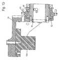
- FIG. 13is a cross-sectional view of a portion of a flexion/extension motion linkage in accordance with embodiments of the invention.
- FIG. 14is a perspective view of the orthopedic simulator of FIG. 1 , with an indication of the lateral bending motion around an axis of rotation.
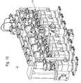
- FIG. 15is a rear perspective view of the orthopedic simulator of FIG. 1 .
- FIG. 16is a perspective view of the orthopedic simulator of FIG. 1 , with an indication of anterior/posterior and lateral translation motions.
- FIG. 17depicts a portion of an x-y slide assembly in accordance with embodiments of the present invention.
- FIG. 18is a perspective view of the x-y slide assembly in accordance with embodiments of the present invention.
- FIG. 19is an exploded view of the x-y slide assembly of FIG. 18 .
- FIG. 20is a perspective view of the orthopedic simulator of FIG. 1 , with an indication of loading in a vertical direction.
- FIG. 21is a perspective view of an embodiment of an actuator in isolation.
- FIG. 22is a top view of the actuator of FIG. 21
- FIG. 23is a side view of the actuator of FIG. 21 .
- FIG. 24is a cross-sectional view of the actuator of FIG. 21 .
- FIG. 25is a perspective view of the orthopedic simulator of FIG. 1 , with an indication of the axial rotation linkage and a moment provided at a test specimen.
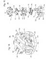
- FIG. 26is a rear perspective view of the orthopedic simulator of FIG. 1 , illustrating an embodiment of a central manifold in accordance with embodiments of the present invention.
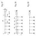
- FIGS. 27-29schematically depict different approaches to linkages.
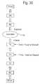
- FIG. 30schematically depicts a nesting order of forces in accordance with embodiments of the present invention.
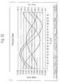
- FIG. 31shows the required forces for application to a test specimen intended for a lumbar region according to an exemplary set of curves.
- FIG. 32shows the same information as FIG. 31 , but for cervical data.
- FIG. 33shows curves for non-sinusoidal input data in accordance with exemplary embodiments of the invention.
- FIG. 34depicts the orthopedic simulator within a housing.
- the orthopedic simulator of the present inventionmay be employed, for example, as a spinal implant wear test machine. In such a configuration, the intent of ISO 18192 is satisfied.
- the orthopedic simulatoris designed for accuracy as well as increased speed.
- the orthopedic simulatoris a spinal implant wear test machine, but it should be apparent to those of ordinary skill in the art that this is exemplary only.
- the features, concepts and designs depicted in the following figures and descriptionmay be employed in other types of machines and orthopedic simulators.
- the embodiments of the present inventionaddress and solve problems related to the translation of a test specimen in an orthopedic simulator and more particularly to fretting and skidding corrosion present in previous translation assemblies, and the provision of multiple operational modes with a single slide table assembly.
- the embodiments of the inventionsolve these problems, at least in part, by providing an orthopedic simulator with a test station configured to hold a test specimen, and a multi-axis slide table on which the test station is mounted for multi-axis movement.
- the multi-axis slide tableincludes a base, a lower translation plate mounted to the base by a first linear slide and rail arrangement for movement along a first axis and an upper translation plate mounted to the lower translation plate by a second linear slide and rail arrangement for movement along a second axis.
- FIG. 1depicts an orthopedic simulator 10 for testing of test specimens of orthopedic devices.
- the orthopedic simulator 10has a plurality of test stations 12 .
- the orthopedic simulator 10is able to provide forces Fx, Fy, and Fz in the x, y and z directions as depicted in FIG. 1 , shown with the x, y and z axes at one of the test stations 12 . Additionally, torques may be applied around the x, y and z axes, as depicted.
- the test specimenis not shown in FIG. 1 so as not to obscure the present invention.
- a specimen containment moduleis provided that contains fluids in which the test specimen is immersed.
- Upper and lower adapters 18(only seen clearly at one of the test stations 12 in which the specimen chamber is removed for illustrative purposes) hold the test specimens between them within the specimen containment module 16 .
- a linkage 20provides forces in the x direction with the linkage 22 providing forces in the y direction.
- Gimbals 24are connected to the upper adapters 18 and may be moved around the y axis and around the x axis to provide moments around the x and y axes.
- Vertical loadsrepresented by forces along the z axis, are provided by vertical load actuators 26 , as shown in FIG. 1 .
- a friction-free axial actuatoris preferable to provide for a friction-free axial/torsion actuation system.
- the vertical load actuator 26applies a vertical loading along the z axis through components 28 to the test specimen via the lower adapter 18 .
- the components 28include an x-y slide table and a load cell.
- An axial rotation linkage 30is coupled to the vertical load actuator 26 .
- the motion of the axial rotation linkage 30is around the vertical axis z, as depicted in FIG. 1 .
- the axial rotation linkage 30is depicted at the bottom of FIG. 1 , it should be apparent to those of skill in the art that the structure depicted in FIG. 1 is suspended vertically so that the axial rotation linkages 30 are free to rotate. This will become more apparent in later-described figures.
- FIGS. 2 a - 2 ddepict alternate views of the orthopedic simulator 10 .
- FIG. 2 ais a top view which best shows the arrangement of the linkages 20 with the gimbals 24 .
- a crosshead 32is provided, which may also best be seen in FIG. 2 d .
- FIG. 2 ais a top view, while FIG. 2 b is a front view, FIG. 2 c is a bottom view and FIG. 2 d is a side view.
- FIG. 3depicts a perspective view of the orthopedic simulator of FIG. 1 , with a specimen containment module 16 that is remote from the orthopedic simulator 10 .
- the specimen containment modules 16are releasably attachable to the test station 12 .
- the releasable attachment feature of each of the specimen containment modules 16enables bench top preparation work on the test specimen to be performed remotely from the environment of the orthopedic simulator 30 .
- This remote loading and preparation capabilityallows for careful removal and insertion of delicate test specimens. Further, the mounting of one-piece specimens is facilitated with this arrangement.
- An important considerationis the reduction in the contamination potential created by remotely mounting a specimen within the specimen containment module.
- the specimen containment module 16also contains adapters 18 that are designed for flexibility, ease of manufacturing and low cost.
- FIG. 4An exemplary embodiment of a specimen containment module 16 is shown in isolation in FIG. 4 , and in exploded view in FIG. 5 .
- the specimen containment modulecontains a base 34 and upper connector 37 that interface to a test station 12 and at which the specimen containment module 16 is releasably attached to the orthopedic simulator 10 .
- a chamber 36when inserted into the moat 38 in the base 34 , forms a fluid container with the base 34 .
- a test specimen 40is depicted with a lower portion 40 a and an upper portion 40 b . However, certain test specimens may also be one-piece specimens.
- Releasable fasteners 42such as thumb screws, may be employed to releasably attach the specimen containment module 16 to the orthopedic simulator 10 .
- Fluid connections 44are used to provide fluid as will be described in more detail in the following figures.
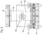
- FIG. 6is a side, partially cross-sectional view of the specimen containment module 16 of FIGS. 4 and 5 .
- the test specimen 40is shown with the upper and lower portions coupled together, as seen in FIG. 6 .
- FIG. 7is a top view of the base 34 .
- a specimen mounting platform 46is provided which includes two pins 48 , with one pin piloting and another pin interacting with a slot in the lower adapter 18 a for anti-rotation purposes. Screw holes 50 are depicted and may be employed to provide a specimen hold down function.
- the base 34also includes a recess 52 that is able to interact with a pin 54 on the orthopedic simulator 10 . This provides a slidable installation of the specimen containment module 16 .
- a tubing loop 56is provided within the base to provide a temperature control of the bath in which the test specimen 40 is immersed. As will be described in more detail, a temperature control fluid is circulated through the tubing loop 56 to precisely control the temperature of the bath. The temperature control fluid does not intermix with the bath fluid.
- a temperature probe 60provides feedback on the temperature of the bath and can be used to control the temperature control fluid. The signal from the temperature probe 60 is provided as a feedback signal to a heather (not shown in FIG. 7 ).
- Recesses 58provide for thumb screws or other releasable fasteners to secure the specimen containment module 16 to the orthopedic simulator 10 .
- Bath fluid circulation tubes 62are used to circulate bath fluid within the fluid container formed by the base 34 and the chamber 36 , as will be described in more detail later with respect to FIG. 9 .
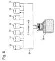
- FIG. 8depicts a circulation loop for circulating the temperature control fluid in the temperature control circuit.
- the temperature control fluidis circulated in each of the specimen containment modules 16 through the tubing loops 56 , seen in FIG. 7 .
- the tubing loops 56are connected to a single circulation loop 64 that circulates a temperature control fluid, such as water, through the closed loop system.
- a temperature control fluidsuch as water
- wateris an exemplary temperature control fluid
- other fluidsmay be employed as a temperature control medium in different embodiments.
- the tempered wateris circulated through the heat exchangers in each of the baths of the specimen containment modules 16 .
- a heater 66provides a precise control and circulation of the tempered water. The heater 66 receives temperature signals from the temperature probes 60 and employs this information to control the temperature of the temperature control fluid, and hence, the bath in each of the specimen containment modules 16 .
- the daisy-chained approach depicted in FIG. 8produces a very stable temperature in each of the baths at the specimen containment modules 16 .
- a consistency of temperature from station 12 to station 12is achieved since the entire circulation loop 64 reaches a stabilized temperature.
- a single heatermay be employed, reducing costs,
- each of the baths of the specimen containment modules 16may be individually controlled with separate circulation loops 65 for each bath.
- Each circulation loop 65has its own heater 66 , which receives temperature feedback signals from the respective temperature probe 60 .
- FIG. 8is preferred.
- the arrangement of FIG. 8 alike that of FIG. 8 , also has the advantage over electric heating elements or other types of heating, in preventing overtemperature related fluid degradation.
- FIG. 9depicts two test stations 12 , one of which has a specimen containment module 16 releasably attached thereto.
- a non-contact level sensor 68such as those known in the sensing art, are provided on posts 70 near the chamber 36 . The height of the non-contact level sensor 68 may be adjusted along the pillar 70 in the direction of arrow 72 . This allows the desired fluid height within the chamber 36 to be precisely adjusted.
- the non-contact level sensor 68provides its signals to a fill controller 74 , schematically indicated as being connected to a non-contact level sensor 68 .
- the fill control 74based upon the signals received from the non-contact level sensors 68 , determines whether the fluid in the specimen containment module 16 needs to be replenished.
- the test fluidsuch as bovine fluid, for example, may evaporate to some extent, thereby increasing the concentration of the fluid. Distilled water is furnished (through a fill tube, not shown) under the control of the fill control 74 .
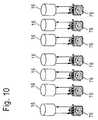
- FIG. 10An arrangement for the circulation of the bath fluid is depicted in FIG. 10 .
- individual loopsare preferred in order to maintain each test specimen and bath in its own environment. In other words, cross-contamination of wear particles is avoided by providing the individual loops for each specimen module.
- peristaltic pumps 76are employed for each of the individual loops. A stirring action is provided.
- FIG. 11shows a specimen containment module 16 (without the chamber 36 for illustrative purposes) in an installed position within the orthopedic simulator 10 .
- the specimen containment moduleis releasably attached at its base 34 to a load cell module 78 .
- the load cell moduleis designed to accommodate either a single or multi-axis force transducer. In the illustrated embodiment, a single axis transducer is depicted.
- FIG. 12depicts the orthopedic simulator 10 and exemplifies the flexion/extension motion.
- the linear actuator 20 a of the linkage 20extends back and forth in an axial manner, causing the connecting link 20 b to translate in an axial direction. This causes the inner gimbals 24 at the test stations 12 to move and rotate around an axis of rotation depicted in FIG. 12 .
- connecting link 20 b and connections to the inner gimbals 24employ high quality bearings, such as long life needle bearings used at key points.
- high quality bearingssuch as long life needle bearings used at key points.
- the designinsures a long life and low lash, creating an accurate machine for a long term use.
- the low moving mass linkage depictedmaximizes performance and is designed for ease of maintenance.
- FIG. 13depicts a cross-sectional portion of the flexion/extension motion linkage.
- the inner gimbal 24is depicted as being connected to the upper specimen adapter 18 b .
- a stationary bearing housing 80houses the needle bearings mentioned before.
- a radial needle bearing 84is provided, as well as a needle roller thrust bearing 82 , which are provided in two places.
- a tubular shaft 86permits rotation of the gimbals 24 .
- FIG. 14A lateral bending motion around the axis of rotation is depicted in FIG. 14 .
- a moving cross-head 32(also seen in FIGS. 2 a - 2 d ) is coupled via a connecting link 88 that is moved by linear actuator 90 in an up-and-down motion. This causes the inner gimbals 24 to be pivoted around the axis of rotation.
- FIG. 15A rear view of the orthopedic simulator 10 is provided in FIG. 15 .
- the moving cross-head 32is shown as extending across the orthopedic simulator 10 .
- a central manifold 92which will be discussed in more detail later.
- long life needle bearingsthat are of high quality at the key points in the lateral bending motion linkages. These designs ensure long life and low lash, creating an accurate machine for long term use.
- the low moving mass crosshead assemblymaximizes performance.
- the crosshead assembly 32may be made of aluminum to provide a very light weight moving mass. In motion, the moving crosshead 32 pivots around the x-axis depicted in FIG. 15 .
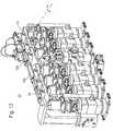
- FIG. 16shows the orthopedic simulator and depicts the anterior/posterior and lateral translation motions.
- a translation stage 96is illustrated in this drawing.
- the translation stageincludes an x-y slide assembly as will be see in the following figures.
- FIG. 17depicts a portion of the x-y slide assembly 100 that shows linear slides 102 with spaces 104 being provided for springs 107 that produce a biasing force if desired.
- the springs 107can be placed between the translation plates 110 , 112 themselves, and between the translation plate 110 and certain lock screw posts 105 of the base 114 , as will be better appreciated in FIG. 18 .
- the configuration of the x-y slide assembly 100 with springs 107places the x-y slide assembly 100 into a shear plane loading operational mode.
- the passive control provided by the springsis replaced with an active control by appropriately placed electric, pneumatic or servo-hydraulic actuators (not depicted).
- actuatorsmay be provided in the spaces 104 .
- the actuatorsare controlled in force and/or displacement via an external control system, such as the controller 200 .
- One of the operating modes that is available with such embodimentsis shear force control, and another operating mode is shear displacement control.
- the Fx and Fy motions and forcestake place in the x-y slide assembly 200 , when in the spring-loaded configuration described above.
- An adjustment systemallows an operator to set the amount of force in each of the x and y axes. This is not a controlled degree of freedom, but rather, there is free translation if an external force overcomes the spring setting.
- spinal implantsthat are simple ball-in-socket joints located coincident with the Mx, My and Mz centers of the machine, the spring is not engaged. However, some specimens would generate crosstalk loading into the Fx/Fy or Fz axes.
- This spring constraining forceallows a user to simulate the soft tissue surrounding a specimen, or intentionally sideload an implant to simulate mis-implantation.
- the passive control provided by the springs 107is replaced by active control through the use of electric, pneumatic or servo-hydraulic actuators.
- a first lock screw post 103 on the base 114receives an adjustable lock screw 101 that is adjusted to interact with the lower translation plate 110 .
- the lock screw 101allows the x-y slide assembly 100 to be placed in an operational mode that provides for infinite positive axis locking of the slide assembly 100 within a dynamic range.
- the second lock screw posts 105also permit locking screws to be received that will interact with the upper translation plate 112 to provide positive axis locking along a different axis from that provided by the lock screw 101 .
- FIG. 18is a perspective view of the x-y slide table 100 constructed in accordance with embodiments of the present invention.
- FIG. 19shows the x-y slide table 100 in an exploded view.
- the x-y slide assembly 100forms a very compact package, with a very light weight assembly.
- Each slide assembly 100also has high moment load ratings, due to its efficient design.
- the x-y slide assembly 100 of the present inventionmay incorporate a number of different modes of operation. These include free-floating to self-center a specimen; a positive axis lock within dynamic range; an ability to produce a large amount of static shear force, on each axis, for simultaneous shear plane loading of specimens; a shear force control and a shear displacement control.
- the x-axis translation platehas a built-in capability to align the upper specimen tooling and the load cell radially.
- the x-y slide assembly 100 of the present inventionovercomes particular concerns. For example, other such assemblies in orthopedic simulators used ball bearings in the slide design which lend themselves to fretting and skidding when translating. Other advantages of the present invention include the production of simultaneous transverse shear in a compact design, while producing friction-free stage floating, but yet is infinitely lockable within a dynamic range. The lowest inertia assembly for Mz rotation is produced, at all six test stations 12 . The design of the x-y slide assembly 100 can withstand a large amount of lbsF in compression. Further, the x-y slide assembly 100 is a translation assembly that can be easily removed from the Fz actuator 26 . It also provides a translation assembly that has over-turning moment capability to react moments caused by side loads that are off-centered loading.
- the x-y slide assembly 100is shown in FIG. 18 in a free-floating configuration, as springs 107 are not provided in the spaces 104 , and adjustable lock screws are not provided in the first lock screw post 103 or the second lock screw posts 105 .
- the x-y slide assembly 100includes the lower translation plate 110 and the upper translation plate 112 .
- the lower translation plate 110translates along the x-axis while the upper translation plate 112 translates along the y axis.
- the base 114supports the x-y slide assembly 100 and may be mounted on the load cell depicted earlier. Pins 116 are provided and pressed into base 114 and lower translation plate 110 .
- the pins 116aid in assembly of the first mounted slide/rail at each axis and ensures squareness of the first rail to the first lock screw post 103 , and establish orthogonality between axis platforms, within the limits of the small screw clearances.
- Screws 118are provided, as well as pin dowels 120 .
- Linear rail bearings 122are provided for linear rails 124 .
- FIG. 20depicts the orthopedic simulator 10 and illustrates the loading in the z direction that is provided in the direction of arrows 128 by the vertical load actuator 26 .
- the integral actuator 26is integral in nature and may be a precision, seal-less actuator design in certain preferred embodiments.
- the piston rodis floated on an oil film, and the near zero friction maximizes the load accuracy.
- a low mass rodmay be employed to maximize the performance of axial rotation and vertical load channels.
- the individual test stations 12have their own on-off valves.
- a perspective view of an actuator 26 in isolationis provided in FIG. 21 .
- a top view of the actuator 26is depicted in FIG. 22 and a side view of the actuator 26 is depicted in FIG. 23 .
- a cross-sectional view of the actuator 26is depicted in FIG. 24 , with an enlargement of a portion from FIG. 24 shown in FIG. 24 a.
- each actuator 26has a handle 130 on the outside of the actuator 26 that operates a built-in hydraulic valve that allows a user to shut off any station individually.
- the actuator 26includes a piston 132 that may be moved axially and rotated.
- the hydraulic actuator 26includes a bottom end cap 134 and a top end cap 136 .
- the hydrostatic bearings 138 and 140are provided. Thrust bearings 142 provide support for a test station 12 when the device is shut off. In such a case, a test station can be removed and the machine operated without the non-operation test station 12 influencing the other test stations 12 .
- Pressure to extend the piston 132 along the z-axisis provided at port 144 , while pressure to retract the piston 132 is provided at port 146 .
- the hydraulic pressure in return ports 144 , 146are connected to and fed from the central manifold 92 (see FIG. 15 ) in preferred embodiments.
- the hydraulic actuator 26is hydrostatic and is completely without seals, including high-pressure piston seals.
- the hydrostatic bearings“float” the piston rod and also provide some over-turning moment capabilities.
- the unique designproduces an actuator without seal drag (as in a typical hydraulic actuator), resulting in a device that has extremely low linear and torsional friction. The only friction is the friction that is produced from viscous oil shear. With this design, an equal Fz force is provided across all seven actuators.
- Thrust bearingsare provided in the end of each end cap 134 , 136 .
- the upper end cap 136has thrust bearings lubricated by a blow-by actuator rod oil leakage. If one specimen should fail before others, an operator can turn off the station 12 .
- the actuator 26retracts and the assembly will ride on the thrust bearings for a continued Mz motion.
- the Mz motionis common for all six Fz actuators 26 at the six test stations 12 .
- the seventh test station 14which operates as a load and soak station for control purposes, is not connected to the Mz drive apparatus.
- the central manifold 92provides an integral manifold for multiple connections and fluid tubing for the orthopedic simulator.
- the use of a central integral manifoldgreatly reduces plumbing, provides a performance improvement since there is a greater balancing of fluid and less plumbing is required, a size reduction, a cost reduction and also serves as a structural element.
- the central manifold 92provides a strong cross-brace for the orthopedic simulator 10 .
- Examples of the plumbinginclude providing the fluid to the extension and retraction fluid connections of the vertical load actuators 26 .
- the central manifold 92also provides for lubrication fluid circulation.
- FIG. 25shows the orthopedic simulator 10 and highlights the axial rotation linkage 30 originally shown in FIG. 1 .
- the axial rotation linkage 30provides a moment Mz at the test specimen.
- FIG. 26which shows a rear view of the orthopedic simulator 10 , a linear actuator 150 , via connecting link 152 , provides the driving force that causes the axial rotation linkages 30 to rotate around the z-axis.
- the axial rotation linkageincludes a rotational transfer link 154 that is coupled to the connecting link 152 . Movement of the connecting link 152 in a linear fashion causes the rotational transfer link 154 to freely rotate on bearings around the z-axis.
- a flexure assembly 156that is torsionally stiff but axially compliant is coupled to the bottom of the piston 132 of the vertical load actuator 26 .
- the flexure assemblyis torsionally stiff so as to rigidly transfer torque between the rotational transfer link 154 and the piston 132 of the actuator 26 .
- a friction free axial/torsion actuationis provided by the combination of the actual rotation linkage 30 and the friction-free vertical force actuator 26 .
- the vertical load actuator 26applies a load to the test specimen 40 along the z-axis by moving the piston 132 along the z-axis.
- the rotational transfer link 154 and the flexure assembly 156facilitate rigid torque transfer to the piston 132 to the test specimen (not shown) at the test station 12 .
- the piston 132is allowed to translate along its axis freely due to the high axial compliance provided by the flexure assembly 56 of the axial rotation linkage 30 .
- FIGS. 27-29depict linkage approaches and highlight the differences between embodiments of the present invention and alternate linkage approaches which provide greater joint serialization error.
- a common sublinkageis provided for the flexion/extension (My) and axial rotation (Mz) to thereby create the fewest common number of joints between each specimen, between the displacement measuring device and each specimen, and between the drive actuator and each specimen. In this manner, variability is minimized.
- the approach provided in the present inventionis depicted in FIG. 27 .
- the solid cross-piece 160provides force to all the linkages 162 at once, from the actuation mechanism 164 .
- FIG. 28employs three separate connecting bars 166 which are connected by two links 168 .
- those test specimens at the left side of FIG. 28have a larger number of joints (8) than the number of joints (4) for the left-most specimen in FIG. 27 .
- Thisincreases the variability in the forces and motions applied to the test specimens from test station 12 to test station 12 .
- a similar variabilityis provided in FIG. 29 , in which a large number of joints are provided for the various test stations, with each test station having a different number of joints.
- the arrangement of the present inventionreduces variability in force and motion application from station 12 to station 12 .
- FIG. 30schematically depicts the nesting order of forces in accordance with embodiments of the present invention. This nesting order of forces is achieved by the arrangement of the linkages as depicted in the figures throughout this application.
- the mechanism systemgenerates relative motions and forces between the lower (inferior) and upper (superior) portions of orthopedic devices, such as multiple intervertebral disc implants, simultaneously to generate wear on the artificial bearing surfaces over similar motion and force induced degradation with time.
- the mechanismapplies these motions and forces in such a way as to maximize the accuracy, test speed and durability of the linkage.
- the full six degree of freedom linkage systemis nested as shown in FIG. 30 to maximize performance and accuracy.
- Typical spinal implant tests in conventional systemsrequire higher displacements in the flexion/extension direction (My), as compared to the lateral bending (Mx) and axial rotation (Mz) rotations. These motions are often performed at a common or similar frequency and wave shapes.
- the mechanism system of the present inventionis nested, however, so as to place the sub-mechanism with the highest required performance closest to the specimen. This thereby minimizes the moving mass and any related inertial induced error.
- the schematically induced specimenis indicated by reference numeral 170 .
- the closest sub-mechanism to the superior (upper) portion of the test specimen 170is the flexion/extension (My).
- the lateral bending (Mx)is further from the superior portion of the specimen 170 , as indicated by FIG. 30 .
- the drive for the Mx and My forcesis furthest away from the specimen 170 .
- the force in the y directionis free, fixed or biased and has a minimized moving mass and has the highest required performance.
- the forces in the x direction Fxis then nested further from the specimen 170 than the Fy force.
- the vertical force provided by the actuator 26 , Fzis still further from the inferior portion of the test specimen 170 , with the moment around the z-axis, Mz, being provided in a nesting arrangement still further from the test specimen 170 .
- the drive for all these forcesis provided as indicated.
- the Euler sequence of rotational motion as applied by the mechanism of the present inventionis flexion/extension ⁇ lateral bending ⁇ axial rotation.
- this ordering of the mechanismpromotes maximum performance and minimizes the additive joint error.
- the independency of linkagesreduces or eliminates cross-talk and allows accurate control of the phases between the individual mechanisms. This is important to create the desired and controlled loading of the test specimen 170 .
- FIG. 31shows the required forces for applying to a test specimen of a spinal implant intended for the lumbar region according to the an exemplary set of curves.
- FIG. 32shows the same information for cervical data.
- Duty cycle loadinginvolves inserting high loads and displacement activity into a more typical repeating activity, such as lifting a heavy box periodically. This allows for the insertion of periodic overload states. Such overload states are known to potentially induce damage, but are relatively rare so that their rarity should be considered and the overload states placed in the context of other daily activity when included.
- embodiments of the present inventionprovide for re-creating any sinusoidal or non-sinusoidal curve, which allows for more accurate simulation (e.g., a “walking simulation”).
- the embodiments of the inventionallow for inputting non-sinusoidal data with varying phase, amplitude and frequency content, such as real walking profiles. These curves, such as shown in FIG. 33 , can be repeated for a large number of cycles, and hence are fatigue or wear generating.
- the representation of activityis not limited to walking, as one of ordinary skill in the art will readily appreciate, but may be used to simulate any number of replicated activities in a serial or repetitive fashion.
- a controller 200seen only in FIG. 1 , is used to independently and individually control each of the motion devices. Hence, the flexion/extension, lateral bending, rotation, and loading of the test specimen 170 may be controlled to any desirable curve through the use of control software and the mechanisms provided in the orthopedic simulator 10 .
- a testmay account for the typical day for humans. Such a day may include sitting for hours at a time with intermittent periods of activity, including walking and sleeping periods. Strenuous physical activity, such as for athletes, may also be better modeled. The controller 200 thereby more accurately causes the orthopedic simulator 10 to simulate the forces that a spinal implant or other orthopedic device will actually be expected to see for a typical implant recipient.
- FIG. 34depicts the orthopedic simulator 10 within a housing 178 .
- the use of a housing 178prevents contamination and reduces oil within the environment.
- Switches 180allow a test station to be shut down very quickly in order to prevent invalidating of a test if an individual test station 12 should experience difficulty in operation.
- the embodiments of the present invention described aboveprovide an orthopedic simulator with a temperature control arrangement for maintaining a specimen bath at a precise temperature, without subjecting the bath fluid to potential over-temperature fluid degradation. Stability and consistency are provided in certain embodiments, as well as cost savings due to use of a single heater and controller.
Landscapes
- Physics & Mathematics (AREA)
- Health & Medical Sciences (AREA)
- Life Sciences & Earth Sciences (AREA)
- Chemical & Material Sciences (AREA)
- Analytical Chemistry (AREA)
- Biochemistry (AREA)
- General Health & Medical Sciences (AREA)
- General Physics & Mathematics (AREA)
- Immunology (AREA)
- Pathology (AREA)
- Prostheses (AREA)
- Accommodation For Nursing Or Treatment Tables (AREA)
Abstract
Description
Claims (28)
Priority Applications (2)
| Application Number | Priority Date | Filing Date | Title |
|---|---|---|---|
| US11/649,962US7913573B2 (en) | 2006-01-13 | 2007-01-05 | Orthopedic simulator with a multi-axis slide table assembly |
| PCT/US2007/000796WO2007082050A2 (en) | 2006-01-13 | 2007-01-10 | Orthopedic simulator with a multi-axis slide table assembly |
Applications Claiming Priority (4)
| Application Number | Priority Date | Filing Date | Title |
|---|---|---|---|
| US11/332,407US7617744B2 (en) | 2006-01-13 | 2006-01-13 | Transmission for torque transfer with axial compliance |
| US76059506P | 2006-01-20 | 2006-01-20 | |
| US11/335,974US7654150B2 (en) | 2006-01-20 | 2006-01-20 | Specimen containment module for orthopedic simulator |
| US11/649,962US7913573B2 (en) | 2006-01-13 | 2007-01-05 | Orthopedic simulator with a multi-axis slide table assembly |
Related Parent Applications (1)
| Application Number | Title | Priority Date | Filing Date |
|---|---|---|---|
| US11/335,974Continuation-In-PartUS7654150B2 (en) | 2006-01-13 | 2006-01-20 | Specimen containment module for orthopedic simulator |
Publications (2)
| Publication Number | Publication Date |
|---|---|
| US20070169572A1 US20070169572A1 (en) | 2007-07-26 |
| US7913573B2true US7913573B2 (en) | 2011-03-29 |
Family
ID=38257033
Family Applications (1)
| Application Number | Title | Priority Date | Filing Date |
|---|---|---|---|
| US11/649,962Active2029-02-05US7913573B2 (en) | 2006-01-13 | 2007-01-05 | Orthopedic simulator with a multi-axis slide table assembly |
Country Status (2)
| Country | Link |
|---|---|
| US (1) | US7913573B2 (en) |
| WO (1) | WO2007082050A2 (en) |
Cited By (3)
| Publication number | Priority date | Publication date | Assignee | Title |
|---|---|---|---|---|
| US20090326889A1 (en)* | 2008-06-25 | 2009-12-31 | Dingmann David L | High Frequency Multi-axis Simulation System |
| US20150052971A1 (en)* | 2013-08-26 | 2015-02-26 | Kun-Ta Lee | Impact testing device |
| US11554030B2 (en)* | 2014-05-23 | 2023-01-17 | Joseph Coggins | Prosthetic limb fitting apparatus for predicting the effect of a proposed prosthetic limb on able joints |
Families Citing this family (11)
| Publication number | Priority date | Publication date | Assignee | Title |
|---|---|---|---|---|
| US7762147B2 (en)* | 2006-01-13 | 2010-07-27 | Mts Systems Corporation | Orthopedic simulator with integral load actuators |
| US7770446B2 (en)* | 2006-01-13 | 2010-08-10 | Mts Systems Corporation | Orthopedic simulator with temperature controller arrangement for controlling temperature of specimen baths |
| US7824184B2 (en) | 2006-01-13 | 2010-11-02 | Mts Systems Corporation | Integrated central manifold for orthopedic simulator |
| US7779708B2 (en)* | 2006-01-13 | 2010-08-24 | Mts Systems Corporation | Orthopedic simulator with fluid concentration maintenance arrangement for controlling fluid concentration of specimen baths |
| US7694593B2 (en) | 2008-05-13 | 2010-04-13 | Bose Corporation | Multi-sample conditioning system |
| CN102650574A (en)* | 2011-08-19 | 2012-08-29 | 高速铁路建造技术国家工程实验室 | Dynamic load simulation device for high-speed railway |
| US9606035B2 (en)* | 2011-12-21 | 2017-03-28 | Ta Instruments-Waters Llc | System for mechanical stimulation and characterization of biologic samples |
| CN102645296B (en)* | 2012-04-16 | 2014-04-02 | 哈尔滨工业大学 | Split-type high-speed electric spindle dynamometer |
| CN103487183B (en)* | 2013-10-11 | 2015-04-15 | 上海宝宜威电子有限公司 | Torque loading device of automatic torque testing system |
| JP6481888B2 (en)* | 2015-01-08 | 2019-03-13 | 学校法人早稲田大学 | Attaching the biological tissue fixture |
| WO2023244798A1 (en)* | 2022-06-17 | 2023-12-21 | Moore Axel Colbert | Off-axis loading fixture for testing spine biomechanics |
Citations (67)
| Publication number | Priority date | Publication date | Assignee | Title |
|---|---|---|---|---|
| GB1108652A (en) | 1965-07-12 | 1968-04-03 | Westinghouse Electric Corp | Human circulatory system simulator |
| US3597967A (en) | 1968-02-26 | 1971-08-10 | Ceskoslovenska Akademie Ved | Apparatus for applying random mechanical loads to a test specimen |
| US3658143A (en) | 1970-11-20 | 1972-04-25 | Nat Controls | Flexure plate scale with hydraulic load cell |
| US3937071A (en) | 1975-07-11 | 1976-02-10 | The United States Of America As Represented By The Secretary Of The Army | Fatigue test apparatus |
| DE2728007B1 (en) | 1977-06-22 | 1978-08-03 | Michael Dr Ungethuem | Simulator for testing total endoprostheses for the hip joint |
| US4196635A (en) | 1977-12-23 | 1980-04-08 | Carl Schenck Ag | Test apparatus for the simultaneous loading of a test sample with longitudinal forces and with torque |
| US4318301A (en) | 1980-06-23 | 1982-03-09 | President And Fellows Of Harvard College | Apparatus for measuring papillary muscle contractility |
| US4428238A (en) | 1981-10-05 | 1984-01-31 | Team Corporation | Vibrating test screening apparatus |
| US4676110A (en) | 1986-07-16 | 1987-06-30 | The United States Of America As Represented By The Administrator Of The National Aeronautics And Space Administration | Fatigue testing a plurality of test specimens and method |
| US4882677A (en) | 1987-09-03 | 1989-11-21 | Curran Thomas M | Isometric strength testing method and equipment for disability evaluation |
| US5009523A (en) | 1989-07-20 | 1991-04-23 | The Timken Company | Double row bearing assembly |
| US5014719A (en) | 1984-02-02 | 1991-05-14 | Mcleod Paul C | Knee loading and testing apparatus and method |
| US5151859A (en) | 1989-06-29 | 1992-09-29 | Honda Giken Kogyo Kabushiki Kaisha | Legged walking robot and system for controlling the same |
| US5259249A (en) | 1991-04-22 | 1993-11-09 | New York University | Hip joint femoral component endoprosthesis test device |
| US5324247A (en) | 1991-11-26 | 1994-06-28 | Alaska Research And Development, Inc. | Apparatus and method for multi-axial spinal testing and rehabilitation |
| US5327038A (en) | 1991-05-09 | 1994-07-05 | Rockwell International Corporation | Walking expansion actuator |
| US5337758A (en) | 1991-01-11 | 1994-08-16 | Orthopedic Systems, Inc. | Spine motion analyzer and method |
| US5360016A (en) | 1991-04-05 | 1994-11-01 | N. K. Biotechnical Engineering Company | Force transducer for a joint prosthesis |
| US5403252A (en) | 1992-05-12 | 1995-04-04 | Life Fitness | Exercise apparatus and method for simulating hill climbing |
| US5415661A (en) | 1993-03-24 | 1995-05-16 | University Of Miami | Implantable spinal assist device |
| DE4411508A1 (en) | 1994-04-02 | 1995-10-05 | Cerasiv Gmbh | Ceramic hip joint ball test appts. |
| US5511431A (en) | 1993-09-24 | 1996-04-30 | Instron Limited | Structure testing machine |
| US5569858A (en) | 1994-05-16 | 1996-10-29 | The B. F. Goodrich Company | Viscoelastic material testing system |
| US5670708A (en) | 1996-04-02 | 1997-09-23 | Endura-Tec Systems Corporation | High frequency intravascular prosthesis fatigue tester |
| US5869328A (en) | 1997-08-08 | 1999-02-09 | Cdc Technologies, Inc. | Cuvette for performing a diagnostic test on a specimen |
| EP0919201A1 (en) | 1997-11-26 | 1999-06-02 | Howmedica Inc. | Kinematic restraint device and method for determining the range of motion of a total knee replacement system |
| US5936858A (en) | 1996-06-27 | 1999-08-10 | Toyota Jidosha Kabushiki Kaisha | Actuator controller for state feedback control |
| US5952582A (en) | 1996-12-27 | 1999-09-14 | Shimadzu Corporation | Test apparatus with control constant computing device |
| US5959215A (en) | 1995-04-12 | 1999-09-28 | Bridgestone Corporation | Heat build-up/fatigue measuring method for viscoelastic body and hydraulic servo flexometer |
| US5999168A (en) | 1995-09-27 | 1999-12-07 | Immersion Corporation | Haptic accelerator for force feedback computer peripherals |
| US6058784A (en) | 1998-02-03 | 2000-05-09 | Mts Systems Corporation | Material testing apparatus having separated load generating mechanisms |
| US6171812B1 (en) | 1997-07-15 | 2001-01-09 | The National Institute Of Biogerontology, Inc. | Combined perfusion and mechanical loading system for explanted bone |
| US20020029610A1 (en) | 2000-05-12 | 2002-03-14 | Chrystall Keith G. | Motion platform and method of use |
| US6418392B1 (en) | 1998-03-20 | 2002-07-09 | National Instruments Corporation | System and method for simulating operations of an instrument |
| US6447448B1 (en) | 1998-12-31 | 2002-09-10 | Ball Semiconductor, Inc. | Miniature implanted orthopedic sensors |
| US6447518B1 (en) | 1995-07-18 | 2002-09-10 | William R. Krause | Flexible shaft components |
| US6472202B1 (en) | 1998-05-08 | 2002-10-29 | Flexcell International Corporation | Loading station assembly and method for tissue engineering |
| US20020166387A1 (en) | 2001-05-09 | 2002-11-14 | Grote Vogel P. | Test specimen holder |
| US20020170361A1 (en) | 2001-05-21 | 2002-11-21 | Enduratec Systems Corp. | Portable device for testing the shear response of a material in response to a repetitive applied force |
| US6502837B1 (en) | 1998-11-11 | 2003-01-07 | Kenmar Company Trust | Enhanced computer optimized adaptive suspension system and method |
| US6510740B1 (en) | 1999-09-28 | 2003-01-28 | Rosemount Inc. | Thermal management in a pressure transmitter |
| US20030029247A1 (en) | 2001-08-10 | 2003-02-13 | Biedermann Motech Gmbh | Sensor device, in particular for a prosthesis, and prosthesis having such a sensor device |
| US20030053901A1 (en) | 1999-08-05 | 2003-03-20 | Roy Shambhu Nath | Parallel kinematics mechanism with a concentric spherical joint |
| US6538215B2 (en) | 2000-01-13 | 2003-03-25 | Sunbeam Products, Inc. | Programmable digital scale |
| US6571373B1 (en) | 2000-01-31 | 2003-05-27 | International Business Machines Corporation | Simulator-independent system-on-chip verification methodology |
| US20030110830A1 (en) | 2001-07-23 | 2003-06-19 | Mark Dehdashtian | Methods and apparatuses for measuring the compliance of stents and stented grafts |
| US6645251B2 (en) | 2001-01-22 | 2003-11-11 | Smith & Nephew, Inc. | Surfaces and processes for wear reducing in orthopaedic implants |
| US6659200B1 (en) | 1999-12-20 | 2003-12-09 | Halliburton Energy Services, Inc. | Actuator assembly and method for actuating downhole assembly |
| US20040019384A1 (en) | 2002-07-24 | 2004-01-29 | Bryan Kirking | Implantable prosthesis for measuring six force components |
| US20040019382A1 (en) | 2002-03-19 | 2004-01-29 | Farid Amirouche | System and method for prosthetic fitting and balancing in joints |
| US6706005B2 (en) | 2000-08-25 | 2004-03-16 | The Cleveland Clinic Foundation | Apparatus and method for assessing loads on adjacent bones |
| US6715336B1 (en) | 2003-02-24 | 2004-04-06 | Npoint, Inc. | Piezoelectric force motion scanner |
| US6721922B1 (en) | 2000-09-27 | 2004-04-13 | Cadence Design Systems, Inc. | System for electronic circuit characterization, analysis, modeling and plan development |
| US6860156B1 (en) | 2004-05-24 | 2005-03-01 | The United States Of America As Represented By The Secretary Of The Navy | Combined in-plane shear and multi-axial tension or compression testing apparatus |
| US6865954B2 (en) | 2003-03-10 | 2005-03-15 | Spinecore, Inc. | Joint simulator testing machine |
| US20050241404A1 (en) | 2004-05-03 | 2005-11-03 | Salvesen William R | Method and apparatus for testing a joint replacement device |
| US7029475B2 (en) | 2003-05-02 | 2006-04-18 | Yale University | Spinal stabilization method |
| US7204160B1 (en) | 2004-05-24 | 2007-04-17 | The United States Of America As Represented By The Secretary Of The Navy | Biaxial and shear testing apparatus with force controls |
| US20070169561A1 (en) | 2006-01-13 | 2007-07-26 | Mts Systems Corporation | Mechanism arrangement for orthopedic simulator |
| US20070169567A1 (en) | 2006-01-20 | 2007-07-26 | Mts Systems Corporation | Duty cycle loading for orthopedic simulator |
| US20070169565A1 (en) | 2006-01-13 | 2007-07-26 | Mts Systems Corporation | Orthopedic simulator with temperature controller arrangement for controlling temperature of specimen baths |
| US20070169573A1 (en) | 2006-01-13 | 2007-07-26 | Mts Systems Corporation | Orthopedic simulator with fluid concentration maintenance arrangement for controlling fluid concentration of specimen baths |
| US20070169566A1 (en) | 2006-01-13 | 2007-07-26 | Mts Systems Corporation | Integrated central manifold for orthopedic simulator |
| US7333111B2 (en) | 2003-04-25 | 2008-02-19 | Honda Giken Kogyo Kabushiki Kaisha | Joint component framework for modeling complex joint behavior |
| US7383738B2 (en)* | 2003-12-05 | 2008-06-10 | Mts Systems Corporation | Method to extend testing through integration of measured responses virtual models |
| US7617744B2 (en)* | 2006-01-13 | 2009-11-17 | Mts Systems Corporation | Transmission for torque transfer with axial compliance |
| US7654150B2 (en) | 2006-01-20 | 2010-02-02 | Mts Systems Corporation | Specimen containment module for orthopedic simulator |
Family Cites Families (2)
| Publication number | Priority date | Publication date | Assignee | Title |
|---|---|---|---|---|
| US7895899B2 (en)* | 2005-12-03 | 2011-03-01 | Kelly Brian P | Multi-axis, programmable spine testing system |
| US7762147B2 (en)* | 2006-01-13 | 2010-07-27 | Mts Systems Corporation | Orthopedic simulator with integral load actuators |
- 2007
- 2007-01-05USUS11/649,962patent/US7913573B2/enactiveActive
- 2007-01-10WOPCT/US2007/000796patent/WO2007082050A2/enactiveApplication Filing
Patent Citations (77)
| Publication number | Priority date | Publication date | Assignee | Title |
|---|---|---|---|---|
| GB1108652A (en) | 1965-07-12 | 1968-04-03 | Westinghouse Electric Corp | Human circulatory system simulator |
| US3597967A (en) | 1968-02-26 | 1971-08-10 | Ceskoslovenska Akademie Ved | Apparatus for applying random mechanical loads to a test specimen |
| US3658143A (en) | 1970-11-20 | 1972-04-25 | Nat Controls | Flexure plate scale with hydraulic load cell |
| US3937071A (en) | 1975-07-11 | 1976-02-10 | The United States Of America As Represented By The Secretary Of The Army | Fatigue test apparatus |
| DE2728007B1 (en) | 1977-06-22 | 1978-08-03 | Michael Dr Ungethuem | Simulator for testing total endoprostheses for the hip joint |
| US4196635A (en) | 1977-12-23 | 1980-04-08 | Carl Schenck Ag | Test apparatus for the simultaneous loading of a test sample with longitudinal forces and with torque |
| US4318301A (en) | 1980-06-23 | 1982-03-09 | President And Fellows Of Harvard College | Apparatus for measuring papillary muscle contractility |
| US4428238A (en) | 1981-10-05 | 1984-01-31 | Team Corporation | Vibrating test screening apparatus |
| US5014719A (en) | 1984-02-02 | 1991-05-14 | Mcleod Paul C | Knee loading and testing apparatus and method |
| US4676110A (en) | 1986-07-16 | 1987-06-30 | The United States Of America As Represented By The Administrator Of The National Aeronautics And Space Administration | Fatigue testing a plurality of test specimens and method |
| US4882677A (en) | 1987-09-03 | 1989-11-21 | Curran Thomas M | Isometric strength testing method and equipment for disability evaluation |
| US5151859A (en) | 1989-06-29 | 1992-09-29 | Honda Giken Kogyo Kabushiki Kaisha | Legged walking robot and system for controlling the same |
| US5009523A (en) | 1989-07-20 | 1991-04-23 | The Timken Company | Double row bearing assembly |
| US5337758A (en) | 1991-01-11 | 1994-08-16 | Orthopedic Systems, Inc. | Spine motion analyzer and method |
| US5360016A (en) | 1991-04-05 | 1994-11-01 | N. K. Biotechnical Engineering Company | Force transducer for a joint prosthesis |
| US5259249A (en) | 1991-04-22 | 1993-11-09 | New York University | Hip joint femoral component endoprosthesis test device |
| US5327038A (en) | 1991-05-09 | 1994-07-05 | Rockwell International Corporation | Walking expansion actuator |
| US5324247A (en) | 1991-11-26 | 1994-06-28 | Alaska Research And Development, Inc. | Apparatus and method for multi-axial spinal testing and rehabilitation |
| US5403252A (en) | 1992-05-12 | 1995-04-04 | Life Fitness | Exercise apparatus and method for simulating hill climbing |
| US5415661A (en) | 1993-03-24 | 1995-05-16 | University Of Miami | Implantable spinal assist device |
| US5511431A (en) | 1993-09-24 | 1996-04-30 | Instron Limited | Structure testing machine |
| DE4411508A1 (en) | 1994-04-02 | 1995-10-05 | Cerasiv Gmbh | Ceramic hip joint ball test appts. |
| US5569858A (en) | 1994-05-16 | 1996-10-29 | The B. F. Goodrich Company | Viscoelastic material testing system |
| US5959215A (en) | 1995-04-12 | 1999-09-28 | Bridgestone Corporation | Heat build-up/fatigue measuring method for viscoelastic body and hydraulic servo flexometer |
| US6447518B1 (en) | 1995-07-18 | 2002-09-10 | William R. Krause | Flexible shaft components |
| US5999168A (en) | 1995-09-27 | 1999-12-07 | Immersion Corporation | Haptic accelerator for force feedback computer peripherals |
| US20010045941A1 (en) | 1995-09-27 | 2001-11-29 | Louis B. Rosenberg | Force feedback system including multiple force processors |
| US5670708A (en) | 1996-04-02 | 1997-09-23 | Endura-Tec Systems Corporation | High frequency intravascular prosthesis fatigue tester |
| US5936858A (en) | 1996-06-27 | 1999-08-10 | Toyota Jidosha Kabushiki Kaisha | Actuator controller for state feedback control |
| US5952582A (en) | 1996-12-27 | 1999-09-14 | Shimadzu Corporation | Test apparatus with control constant computing device |
| US6171812B1 (en) | 1997-07-15 | 2001-01-09 | The National Institute Of Biogerontology, Inc. | Combined perfusion and mechanical loading system for explanted bone |
| US5869328A (en) | 1997-08-08 | 1999-02-09 | Cdc Technologies, Inc. | Cuvette for performing a diagnostic test on a specimen |
| US5937530A (en) | 1997-11-26 | 1999-08-17 | Masson; Martin | Kinematic restraint device and method for determining the range of motion of a total knee replacement system |
| EP0919201A1 (en) | 1997-11-26 | 1999-06-02 | Howmedica Inc. | Kinematic restraint device and method for determining the range of motion of a total knee replacement system |
| US6058784A (en) | 1998-02-03 | 2000-05-09 | Mts Systems Corporation | Material testing apparatus having separated load generating mechanisms |
| US6418392B1 (en) | 1998-03-20 | 2002-07-09 | National Instruments Corporation | System and method for simulating operations of an instrument |
| US6472202B1 (en) | 1998-05-08 | 2002-10-29 | Flexcell International Corporation | Loading station assembly and method for tissue engineering |
| US6502837B1 (en) | 1998-11-11 | 2003-01-07 | Kenmar Company Trust | Enhanced computer optimized adaptive suspension system and method |
| US6447448B1 (en) | 1998-12-31 | 2002-09-10 | Ball Semiconductor, Inc. | Miniature implanted orthopedic sensors |
| US20030053901A1 (en) | 1999-08-05 | 2003-03-20 | Roy Shambhu Nath | Parallel kinematics mechanism with a concentric spherical joint |
| US6510740B1 (en) | 1999-09-28 | 2003-01-28 | Rosemount Inc. | Thermal management in a pressure transmitter |
| US6659200B1 (en) | 1999-12-20 | 2003-12-09 | Halliburton Energy Services, Inc. | Actuator assembly and method for actuating downhole assembly |
| US6538215B2 (en) | 2000-01-13 | 2003-03-25 | Sunbeam Products, Inc. | Programmable digital scale |
| US6571373B1 (en) | 2000-01-31 | 2003-05-27 | International Business Machines Corporation | Simulator-independent system-on-chip verification methodology |
| US20020029610A1 (en) | 2000-05-12 | 2002-03-14 | Chrystall Keith G. | Motion platform and method of use |
| US6581437B2 (en) | 2000-05-12 | 2003-06-24 | Alberta Research Council Inc. | Motion platform and method of use |
| US6706005B2 (en) | 2000-08-25 | 2004-03-16 | The Cleveland Clinic Foundation | Apparatus and method for assessing loads on adjacent bones |
| US6721922B1 (en) | 2000-09-27 | 2004-04-13 | Cadence Design Systems, Inc. | System for electronic circuit characterization, analysis, modeling and plan development |
| US6645251B2 (en) | 2001-01-22 | 2003-11-11 | Smith & Nephew, Inc. | Surfaces and processes for wear reducing in orthopaedic implants |
| US20020166387A1 (en) | 2001-05-09 | 2002-11-14 | Grote Vogel P. | Test specimen holder |
| US6629466B2 (en) | 2001-05-09 | 2003-10-07 | Mts Systems Corporation | Test specimen holder |
| US20020170361A1 (en) | 2001-05-21 | 2002-11-21 | Enduratec Systems Corp. | Portable device for testing the shear response of a material in response to a repetitive applied force |
| US20030110830A1 (en) | 2001-07-23 | 2003-06-19 | Mark Dehdashtian | Methods and apparatuses for measuring the compliance of stents and stented grafts |
| US20030029247A1 (en) | 2001-08-10 | 2003-02-13 | Biedermann Motech Gmbh | Sensor device, in particular for a prosthesis, and prosthesis having such a sensor device |
| US20040019382A1 (en) | 2002-03-19 | 2004-01-29 | Farid Amirouche | System and method for prosthetic fitting and balancing in joints |
| US20040019384A1 (en) | 2002-07-24 | 2004-01-29 | Bryan Kirking | Implantable prosthesis for measuring six force components |
| US6715336B1 (en) | 2003-02-24 | 2004-04-06 | Npoint, Inc. | Piezoelectric force motion scanner |
| US7284446B2 (en) | 2003-03-10 | 2007-10-23 | Spinecore, Inc. | Joint simulator testing machine |
| US6865954B2 (en) | 2003-03-10 | 2005-03-15 | Spinecore, Inc. | Joint simulator testing machine |
| US20050056099A1 (en) | 2003-03-10 | 2005-03-17 | Spinecore, Inc. | Joint simulator testing machine |
| US7040177B2 (en) | 2003-03-10 | 2006-05-09 | Spinecore, Inc. | Joint simulator testing machine |
| US7131338B2 (en) | 2003-03-10 | 2006-11-07 | Spinecore, Inc. | Joint simulator testing machine |
| US7357038B2 (en) | 2003-03-10 | 2008-04-15 | Spinecore, Inc. | Joint simulator testing machine |
| US7333111B2 (en) | 2003-04-25 | 2008-02-19 | Honda Giken Kogyo Kabushiki Kaisha | Joint component framework for modeling complex joint behavior |
| US7029475B2 (en) | 2003-05-02 | 2006-04-18 | Yale University | Spinal stabilization method |
| US7383738B2 (en)* | 2003-12-05 | 2008-06-10 | Mts Systems Corporation | Method to extend testing through integration of measured responses virtual models |
| US20050241404A1 (en) | 2004-05-03 | 2005-11-03 | Salvesen William R | Method and apparatus for testing a joint replacement device |
| US7219555B2 (en) | 2004-05-03 | 2007-05-22 | Salvesen William R | Method and apparatus for testing a joint replacement device |
| US6860156B1 (en) | 2004-05-24 | 2005-03-01 | The United States Of America As Represented By The Secretary Of The Navy | Combined in-plane shear and multi-axial tension or compression testing apparatus |
| US7204160B1 (en) | 2004-05-24 | 2007-04-17 | The United States Of America As Represented By The Secretary Of The Navy | Biaxial and shear testing apparatus with force controls |
| US20070169573A1 (en) | 2006-01-13 | 2007-07-26 | Mts Systems Corporation | Orthopedic simulator with fluid concentration maintenance arrangement for controlling fluid concentration of specimen baths |
| US20070169566A1 (en) | 2006-01-13 | 2007-07-26 | Mts Systems Corporation | Integrated central manifold for orthopedic simulator |
| US20070169565A1 (en) | 2006-01-13 | 2007-07-26 | Mts Systems Corporation | Orthopedic simulator with temperature controller arrangement for controlling temperature of specimen baths |
| US20070169561A1 (en) | 2006-01-13 | 2007-07-26 | Mts Systems Corporation | Mechanism arrangement for orthopedic simulator |
| US7617744B2 (en)* | 2006-01-13 | 2009-11-17 | Mts Systems Corporation | Transmission for torque transfer with axial compliance |
| US20070169567A1 (en) | 2006-01-20 | 2007-07-26 | Mts Systems Corporation | Duty cycle loading for orthopedic simulator |
| US7654150B2 (en) | 2006-01-20 | 2010-02-02 | Mts Systems Corporation | Specimen containment module for orthopedic simulator |
Non-Patent Citations (16)
| Title |
|---|
| "Notification of Transmittal of the International Search Report and the Written Opinion of the International Searching Authority, or the Declaration" for related foreign application No. PCT/US/2007/00727 filed Jan. 10, 2007; date of mailing May 8, 2008; 8 pages. |
| "Notification of Transmittal of the International Search Report and the Written Opinion of the International Searching Authority, or the Declaration" for related foreign application No. PCT/US/2007/00733 filed Jan. 10, 2007; date of mailing Oct. 1, 2007; 8 pages. |
| "Notification of Transmittal of the International Search Report and the Written Opinion of the International Searching Authority, or the Declaration" for related foreign application No. PCT/US/2007/00797 filed Jan. 10, 2007; date of mailing Feb. 26, 2008; 11 pages. |
| "Notification of Transmittal of the International Search Report and the Written Opinion of the International Searching Authority, or the Declaration" for related foreign application No. PCT/US/2007/00799 filed Jan. 10, 2007; date of mailing Jul. 15, 2008; 8 pages. |
| Biomechanical Materials Testing Laboratory [online]. Flinders University, Adelaide, Australia, 2003 [retrieved on Aug. 7, 2007]. Retrieved from www,archive.org using the Internet: . p. 3,para 7,p. 1, para 3,p. 3, para 3, p. 2, para 7, p. 2, para 11; 4 pages. |
| Biomechanical Materials Testing Laboratory [online]. Flinders University, Adelaide, Australia, 2003 [retrieved on Aug. 7, 2007]. Retrieved from www,archive.org using the Internet: <URL:http://web.archive.org/web/20030825155452/http://som.flinders,edu.au/FUSA/ORTHOWEB/lab. Htm>. p. 3,para 7,p. 1, para 3,p. 3, para 3, p. 2, para 7, p. 2, para 11; 4 pages. |
| International Preliminary Report on Patentability PCT/US07/00727 dated Jul. 15, 2008; one page. |
| International Preliminary Report on Patentability PCT/US07/00797 dated Jul. 15, 2008; one page. |
| International Preliminary Report on Patentability PCT/US07/00799 dated Aug. 26, 2008; one page. |
| International Preliminary Report on Patentability PCT/US2007/000796 dated Jul. 15, 2008. |
| International Search Report PCT./US/07/00727 dated Dec. 28, 2004, one page. |
| International Search Report/Written Opinion PCT/US2007/00796 mailed Mar. 27, 2008. |
| PCT International Search Report and Written Opinion of the International Searching Authority, PCT/US2004/040798 dated Jun. 4, 2005; one page. |
| Prosthetic Knee Tester, 6 Station Knee Simulator [online]. ATMI—Boston, Nov. 6, 2005 [retrieved on Jul. 6, 2007.] Retrieved from the Internet: <URL:http://web.archive.org/web/20051106114417/http:/www.amtiweb.com/sim/knee—machine1.htm> Entire document. |
| Prosthetic Knee Tester, 6 Station Knee Simulator [online]. ATMI-Boston, Nov. 6, 2005 [retrieved on Jul. 6, 2007.] Retrieved from the Internet: Entire document. |
| Written Opinion of the International Searching Authority PCT/US07/00727 mailed May 5, 2008; 3 pages. |
Cited By (5)
| Publication number | Priority date | Publication date | Assignee | Title |
|---|---|---|---|---|
| US20090326889A1 (en)* | 2008-06-25 | 2009-12-31 | Dingmann David L | High Frequency Multi-axis Simulation System |
| US7966890B2 (en)* | 2008-06-25 | 2011-06-28 | Bose Corporation | High frequency multi-axis simulation system |
| US20150052971A1 (en)* | 2013-08-26 | 2015-02-26 | Kun-Ta Lee | Impact testing device |
| US9310282B2 (en)* | 2013-08-26 | 2016-04-12 | Kun-Ta Lee | Impact testing device |
| US11554030B2 (en)* | 2014-05-23 | 2023-01-17 | Joseph Coggins | Prosthetic limb fitting apparatus for predicting the effect of a proposed prosthetic limb on able joints |
Also Published As
| Publication number | Publication date |
|---|---|
| WO2007082050A3 (en) | 2008-07-31 |
| WO2007082050A2 (en) | 2007-07-19 |
| US20070169572A1 (en) | 2007-07-26 |
Similar Documents
| Publication | Publication Date | Title |
|---|---|---|
| US7913573B2 (en) | Orthopedic simulator with a multi-axis slide table assembly | |
| US8156824B2 (en) | Mechanism arrangement for orthopedic simulator | |
| US7770446B2 (en) | Orthopedic simulator with temperature controller arrangement for controlling temperature of specimen baths | |
| CN101379379A (en) | Duty cycle loading for orthopedic simulator | |
| US20070169567A1 (en) | Duty cycle loading for orthopedic simulator | |
| US7824184B2 (en) | Integrated central manifold for orthopedic simulator | |
| US7895899B2 (en) | Multi-axis, programmable spine testing system | |
| Stokes et al. | Measurement of a spinal motion segment stiffness matrix | |
| US7779708B2 (en) | Orthopedic simulator with fluid concentration maintenance arrangement for controlling fluid concentration of specimen baths | |
| CN100520333C (en) | High frequency multiple degree of freedom vibration test machine | |
| US9351857B2 (en) | Method and apparatus for joint motion simulation | |
| Walker et al. | A knee simulating machine for performance evaluation of total knee replacements | |
| US6223604B1 (en) | Mobile truss testing apparatus | |
| JP2002286608A (en) | Artificial joint friction and wear tester | |
| US7762147B2 (en) | Orthopedic simulator with integral load actuators | |
| EP1977200A2 (en) | Duty cycle loading for orthopedic simulator | |
| Mejia et al. | A hip wear simulator for the evaluation of biomaterials in hip arthroplasty components | |
| DeLucca et al. | Off‐axis response due to mechanical coupling across all six degrees of freedom in the human disc | |
| Ansaripour et al. | In vitro biomechanics of the cervical spine: A systematic review | |
| WO2006018603A1 (en) | Improvements in and relating to testing | |
| Galbusera et al. | In vitro testing of cadaveric specimens | |
| Oliveira et al. | Development of a protocol for the performance evaluation of wear machines used in tests of joint prostheses | |
| Moore et al. | Off-Axis Loading fixture for spine biomechanics: Combined Compression and bending | |
| Hung et al. | Design of a biaxial test device for compliant tissue | |
| Park et al. | A novel accelerated fatigue testing system for pulsatile applications of cardiac devices using widely translatable cam and linkage-based mechanisms |
Legal Events
| Date | Code | Title | Description |
|---|---|---|---|
| AS | Assignment | Owner name:MTS SYSTEMS CORPORATION, MINNESOTA Free format text:ASSIGNMENT OF ASSIGNORS INTEREST;ASSIGNORS:SCHULZ, BRADLEY D.;LESKA, SR., PAUL J.;WILLIS, DENNIS J.;AND OTHERS;REEL/FRAME:018774/0140;SIGNING DATES FROM 20061222 TO 20070102 Owner name:MTS SYSTEMS CORPORATION, MINNESOTA Free format text:ASSIGNMENT OF ASSIGNORS INTEREST;ASSIGNORS:SCHULZ, BRADLEY D.;LESKA, SR., PAUL J.;WILLIS, DENNIS J.;AND OTHERS;SIGNING DATES FROM 20061222 TO 20070102;REEL/FRAME:018774/0140 | |
| STCF | Information on status: patent grant | Free format text:PATENTED CASE | |
| FPAY | Fee payment | Year of fee payment:4 | |
| AS | Assignment | Owner name:JPMORGAN CHASE BANK, N.A., AS ADMINISTRATIVE AGENT, ILLINOIS Free format text:SUPPLEMENTAL CONFIRMATORY GRANT OF SECURITY INTEREST IN UNITED STATES PATENTS;ASSIGNOR:MTS SYSTEMS CORPORATION;REEL/FRAME:039258/0587 Effective date:20160705 Owner name:JPMORGAN CHASE BANK, N.A., AS ADMINISTRATIVE AGENT Free format text:SUPPLEMENTAL CONFIRMATORY GRANT OF SECURITY INTEREST IN UNITED STATES PATENTS;ASSIGNOR:MTS SYSTEMS CORPORATION;REEL/FRAME:039258/0587 Effective date:20160705 | |
| MAFP | Maintenance fee payment | Free format text:PAYMENT OF MAINTENANCE FEE, 8TH YEAR, LARGE ENTITY (ORIGINAL EVENT CODE: M1552) Year of fee payment:8 | |
| AS | Assignment | Owner name:MTS SYSTEMS CORPORATION, MINNESOTA Free format text:RELEASE BY SECURED PARTY;ASSIGNOR:JPMORGAN CHASE BANK, N.A., AS ADMINISTRATIVE AGENT;REEL/FRAME:055911/0315 Effective date:20210407 | |
| MAFP | Maintenance fee payment | Free format text:PAYMENT OF MAINTENANCE FEE, 12TH YEAR, LARGE ENTITY (ORIGINAL EVENT CODE: M1553); ENTITY STATUS OF PATENT OWNER: LARGE ENTITY Year of fee payment:12 |