US7911817B2 - Systems and methods for controlling energy consumption of AC-DC adapters - Google Patents
Systems and methods for controlling energy consumption of AC-DC adaptersDownload PDFInfo
- Publication number
- US7911817B2 US7911817B2US12/284,144US28414408AUS7911817B2US 7911817 B2US7911817 B2US 7911817B2US 28414408 AUS28414408 AUS 28414408AUS 7911817 B2US7911817 B2US 7911817B2
- Authority
- US
- United States
- Prior art keywords
- adapter
- power
- powered device
- load
- communicated
- Prior art date
- Legal status (The legal status is an assumption and is not a legal conclusion. Google has not performed a legal analysis and makes no representation as to the accuracy of the status listed.)
- Active, expires
Links
Images


Classifications
- H—ELECTRICITY
- H02—GENERATION; CONVERSION OR DISTRIBUTION OF ELECTRIC POWER
- H02M—APPARATUS FOR CONVERSION BETWEEN AC AND AC, BETWEEN AC AND DC, OR BETWEEN DC AND DC, AND FOR USE WITH MAINS OR SIMILAR POWER SUPPLY SYSTEMS; CONVERSION OF DC OR AC INPUT POWER INTO SURGE OUTPUT POWER; CONTROL OR REGULATION THEREOF
- H02M3/00—Conversion of DC power input into DC power output
- H02M3/22—Conversion of DC power input into DC power output with intermediate conversion into AC
- H02M3/24—Conversion of DC power input into DC power output with intermediate conversion into AC by static converters
- H02M3/28—Conversion of DC power input into DC power output with intermediate conversion into AC by static converters using discharge tubes with control electrode or semiconductor devices with control electrode to produce the intermediate AC
- H02M3/325—Conversion of DC power input into DC power output with intermediate conversion into AC by static converters using discharge tubes with control electrode or semiconductor devices with control electrode to produce the intermediate AC using devices of a triode or a transistor type requiring continuous application of a control signal
- H02M3/335—Conversion of DC power input into DC power output with intermediate conversion into AC by static converters using discharge tubes with control electrode or semiconductor devices with control electrode to produce the intermediate AC using devices of a triode or a transistor type requiring continuous application of a control signal using semiconductor devices only
- H—ELECTRICITY
- H02—GENERATION; CONVERSION OR DISTRIBUTION OF ELECTRIC POWER
- H02M—APPARATUS FOR CONVERSION BETWEEN AC AND AC, BETWEEN AC AND DC, OR BETWEEN DC AND DC, AND FOR USE WITH MAINS OR SIMILAR POWER SUPPLY SYSTEMS; CONVERSION OF DC OR AC INPUT POWER INTO SURGE OUTPUT POWER; CONTROL OR REGULATION THEREOF
- H02M1/00—Details of apparatus for conversion
- H02M1/0003—Details of control, feedback or regulation circuits
- H02M1/0032—Control circuits allowing low power mode operation, e.g. in standby mode
- Y—GENERAL TAGGING OF NEW TECHNOLOGICAL DEVELOPMENTS; GENERAL TAGGING OF CROSS-SECTIONAL TECHNOLOGIES SPANNING OVER SEVERAL SECTIONS OF THE IPC; TECHNICAL SUBJECTS COVERED BY FORMER USPC CROSS-REFERENCE ART COLLECTIONS [XRACs] AND DIGESTS
- Y02—TECHNOLOGIES OR APPLICATIONS FOR MITIGATION OR ADAPTATION AGAINST CLIMATE CHANGE
- Y02B—CLIMATE CHANGE MITIGATION TECHNOLOGIES RELATED TO BUILDINGS, e.g. HOUSING, HOUSE APPLIANCES OR RELATED END-USER APPLICATIONS
- Y02B70/00—Technologies for an efficient end-user side electric power management and consumption
- Y02B70/10—Technologies improving the efficiency by using switched-mode power supplies [SMPS], i.e. efficient power electronics conversion e.g. power factor correction or reduction of losses in power supplies or efficient standby modes
Definitions
- This inventionrelates generally to AC-DC adapters, and more particularly to controlling energy consumption by AC-DC adapters.
- An information handling systemgenerally processes, compiles, stores, and/or communicates information or data for business, personal, or other purposes thereby allowing users to take advantage of the value of the information.
- information handling systemsmay also vary regarding what information is handled, how the information is handled, how much information is processed, stored, or communicated, and how quickly and efficiently the information may be processed, stored, or communicated.
- the variations in information handling systemsallow for information handling systems to be general or configured for a specific user or specific use such as financial transaction processing, airline reservations, enterprise data storage, or global communications.
- information handling systemsmay include a variety of hardware and software components that may be configured to process, store, and communicate information and may include one or more computer systems, data storage systems, and networking systems.
- External AC-DC adapters or power suppliesare commonly employed to convert alternating current (AC) wall current to direct current (DC) for powering DC-powered devices, including DC-powered information handling systems such as notebook computers.
- AC-DC adaptersare commonly left connected to wall current power sources even when not connected to a DC-powered device or when connected to a DC-powered device that is not drawing current. Under such conditions, a typical AC-DC adapter remains on and consumes energy.
- current Tier 2 “ENERGY STAR” program requirementsspecify a maximum no load AC power consumption of less than or equal to 0.5 watts for an external power supply having a nameplate output power rating of less than 10 watts.
- Most conventional AC-DC power suppliesmeet this maximum no load AC power consumption requirement by running in a reduced frequency “burst mode.” However, during such a conventional burst mode, the power supply output remains on, and the burst frequency can cause audible issues.
- no load energy consumption of an AC-DC adaptermay be reduced relative to conventional adapter energy consumption under no load conditions, e.g., such as when an adapter is plugged into a wall power source but not connected to a DC-powered device, or when an adapter is plugged into a wall power source but is coupled to a DC-powered device that is not drawing current.
- an AC-DC adaptermay be advantageously configured to consume about 0.25 watts less power than a conventional 0.5 watt adapter, driving total no load power consumption below about 0.25 watts.
- an AC-DC adaptermay be provided with an auto-sensing capability to sense when no DC load is present at the output (secondary side) of the adapter by monitoring for absence of load-indicative signals (e.g., communication signal such as power supply identifier (PSID) signal, current indicative signal such as current level signal, etc.), communicated to the adapter from a DC-powered device.
- load-indicative signalse.g., communication signal such as power supply identifier (PSID) signal, current indicative signal such as current level signal, etc.
- the adapterUpon detection of such a no load condition, the adapter enters a no load mode and the adapter output is turned off (i.e., V OUT equal to 0 volts at the adapter output) in order to reduce energy consumption by the adapter.
- V OUTequal to 0 volts at the adapter output
- the adapter outputremains at 0 volts except for producing short recurring voltage pulses (hiccups) at the adapter output which are provided for purposes of powering load-indicative signal-generating circuitry (e.g., PSID circuitry) of any active DC-powered device that may become coupled to the adapter output after the adapter enters the no load mode.
- load-indicative signal-generating circuitrye.g., PSID circuitry
- load-indicative circuitryWhen so powered, such load-indicative circuitry will produce load-indicative signals that are communicated back to the adapter via the adapter power cord.
- the adapter outputUpon detection of load-indicative signals communicated to the adapter (e.g., by a connected DC-powered device such as notebook computer), the adapter output enters normal mode and provides its normal regulated output voltage to the adapter output for powering the coupled DC-powered device under normal operating conditions.
- an AC-DC adaptermay be provided with auto-sensing capability by inclusion of an auto-sensing circuitry that is tied to the PSID communication pin of the adapter.
- a buffer stagemay be provided in the auto-sensing circuitry so that communicated PSID signals are not substantially affected by the remainder of the auto-sensing circuitry in order to ensure that PSID communication between a DC-powered device and the adapter is unaltered.
- a capacitor or other suitable charge-storing circuitrymay be provided in the auto-sensing circuitry that is charged by PSID communication pulses communicated from the DC-powered device to the adapter.
- the auto-sensing circuitrymay include a comparator or other circuitry suitable for detecting the presence of PSID-induced charge on the capacitor or other charge-storing circuitry, and for producing a signal indicative of the absence and/or presence of PSID-induced charge which is in turn communicated from the auto-sensing circuitry to adapter switching control circuitry, e.g., through an optocoupler or other suitable isolation circuitry.
- adapter switching control circuitrye.g., through an optocoupler or other suitable isolation circuitry.
- any other configuration of circuitrymay be provided that is suitable for sensing the presence of PSID signals and providing a signal to the adapter controller that is indicative thereof.
- the switching control circuitrymay be configured to vary the output mode of the adapter based on the nature of the signal received from the auto-sensing circuitry, e.g., so that the adapter provides normal regulated power at the adapter output when the presence of PSID signals are detected, while it provides no power at the adapter output other than short recurring voltage pulses (hiccups) in the absence of any such PSID signals.
- the methodmay include the method, including: providing an AC-DC adapter configured to convert AC power to DC power and to provide the DC power to a DC-powered device at a DC power output of the AC-DC adapter, the AC-DC adapter being further configured to receive load-indicative signals from a DC-powered device; providing AC power to an AC input of the AC-DC adapter; monitoring for the presence of load-indicative signals communicated from a DC-powered device to the AC-DC adapter while providing the AC power to the AC input of the AC-DC adapter; and controlling energy consumption of the AC-DC adapter by: operating the AC-DC adapter so as to provide a first level of DC power at the DC power output that is sufficient for powering a DC-powered device while load-indicative signals are being communicated to the AC-DC adapter from a DC powered device, and operating the AC-DC adapter so as to provide a second level of DC power at the DC power output while load-
- an AC-DC adapterincluding: AC to DC conversion circuitry configured to receive AC current and to convert the AC current to DC current; power switching circuitry coupled between the AC to DC conversion circuitry and a DC power output of the AC adapter that is configured for coupling to supply DC power to a DC-powered device, the power switching circuitry being configured to regulate DC power provided from the AC to DC conversion circuitry to the DC power output; switch control circuitry coupled to the power switching circuitry, the switch control circuitry being configured to control operation of the power switching circuitry; load-indicative signal generating circuitry configured to receive load-indicative signals from a DC-powered device; and auto-sensing circuitry coupled to the load-indicative signal generating circuitry, the auto-sensing circuitry configured to monitor for the presence of load-indicative signals communicated from a DC-powered device to the load-indicative signal generating circuitry of the AC-DC adapter.
- the auto-sensing circuitrymay be configured to provide a signal to the switch control circuitry that is indicative of the presence of load-indicative signals communicated from a DC-powered device to the load-indicative signal generating circuitry of the AC-DC adapter; and the switch control circuitry may be configured to control energy consumption of the AC-DC adapter by: controlling the power switching circuitry so as to provide a first level of DC power at the DC power output that is sufficient for powering a DC-powered device while load-indicative signals are being communicated to the AC-DC adapter from a DC powered device, and controlling the power switching circuitry so to provide a second level of DC power at the DC power output while load-indicative signals are not being communicated to the AC-DC adapter from a DC powered device; wherein the second level of DC power is less than the first level of DC power.
- a method of powering a DC-powered deviceincluding: providing a DC-powered device; providing an AC-DC adapter; providing AC power to an AC input of the AC-DC adapter; coupling the AC-DC adapter to the DC-powered device to provide DC power to the DC-powered device, and to provide load-indicative signals from the DC-powered device to the AC-DC adapter; providing a first level of DC power to the DC-powered device from the AC-DC adapter, the first level of DC power being sufficient for powering the DC-powered device, including powering the generation of load-indicative signals from the DC-powered device to the AC-DC adapter; monitoring for the presence of the load-indicative signals communicated from the DC-powered device to the AC-DC adapter; and controlling energy consumption of the AC-DC adapter by: operating the AC-DC adapter so as to provide the first level of DC power to the DC-powered device as long as the load-indicative signals are being communicated to the AC-DC adapter from the
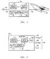
- FIG. 1is a simplified block diagram of an AC-DC adapter coupled to a DC-powered information handling system according to one exemplary embodiment of the disclosed systems and methods.
- FIG. 2is a simplified block diagram of an AC-DC adapter according to one exemplary embodiment of the disclosed systems and methods.
- FIG. 3is a simplified partial schematic of AC-DC adapter-side circuitry according to one exemplary embodiment of the disclosed systems and methods.
- FIG. 4illustrates PSID signals and capacitor voltage as a function of time according to one exemplary embodiment of the disclosed systems and methods.
- FIG. 5illustrates FIG. 5 illustrates adapter output voltage a function of time according to one exemplary embodiment of the disclosed systems and methods.
- FIG. 1illustrates a DC-powered information handling system in the form of a notebook computer 100 that is coupled by a DC power cord 108 to an AC-DC adapter 102 according to one embodiment of the disclosed systems and methods.
- AC-DC adapter 102is configured to receive AC wall power via AC power cord 106 and power plug 104 , to convert the provided AC power to DC power, and to provide the DC power to notebook computer 100 via DC power cord 108 .
- notebook computer 100includes a system load (e.g., processor/s, display, disk drive/s, communication circuitry, one or more batteries, battery charging circuitry, etc.) that is powered by the DC power so provided by AC-DC adapter 102 .
- a notebook computer 100is illustrated, it will be understood that the disclosed systems and methods may be implemented with any other type of information handling system or other device having a system load that is DC powered.
- AC-DC adapter 102includes switch control circuitry 110 , such as pulse width modulation (PWM) integrated circuitry or other suitable control circuitry. Also shown in FIG. 2 are respective V OUT + , V ⁇ and PSID pins 202 , 204 and 200 of adapter 102 , which couple to corresponding individual respective conductors of power DC power cord 108 .
- AC-DC adapter 1 - 02also includes power switching circuitry 114 that is coupled between AC to DC conversion circuitry 116 (e.g., AC to DC transformer) and V OUT + and V ⁇ pins 202 and 204 of adapter 102 .
- Power switching circuitry 114may include any type of switch circuitry (e.g., such as metal oxide semiconductor field-effect transistor (MOSFET) switches) that is suitable for regulating supply of DC current from the adapter DC current source to pins 202 and 204 of adapter 102 .
- switch circuitrye.g., such as metal oxide semiconductor field-effect transistor (MOSFET) switches
- MOSFETmetal oxide semiconductor field-effect transistor
- switch control circuitry 110controls DC current output by adapter 102 via pins 202 and 204 through corresponding conductors of power cord 108 to notebook computer 100 by controlling power switching circuitry 114 between ON and OFF states to produce a continuous level of non-zero voltage.
- switch control circuitry 110may control power switching circuitry 114 to allow a continuous flow of DC current to pins 202 and 204 in an ON state, or may regulate DC current output to pins 202 and 204 by controlling power switching circuitry 114 between ON and OFF states to control duty cycle (i.e., frequency and/or pulse length) of power output by adapter 102 to notebook computer 100 .
- duty cyclei.e., frequency and/or pulse length
- auto-sensing circuitry 112that is configured to sense when no DC load is present at the V OUT + and V ⁇ pins 202 and 204 of adapter 102 by monitoring for absence of PSID signals communicated from notebook computer 100 to PSID circuitry 304 of adapter 102 through PSID pin 200 , e.g., such as when adapter 102 is not coupled to supply power to notebook computer 100 , or when adapter 102 is coupled to notebook computer 100 but notebook computer 100 is inactive.
- auto-sensing circuitry 112Upon detection of such a no load condition, auto-sensing circuitry 112 instructs switch control circuitry 110 to enter a no load mode, which in turn controls power switching circuitry 114 so as to turn-off power output from adapter 102 to notebook computer 100 via pins 202 and 204 in a manner that reduces energy consumption by adapter 102 .
- a load-indicative signalmay be a current-indicative signal (e.g., generated by a current transformer or shunt circuitry of a motherboard of the DC-powered device) that is representative of current level drawn by circuitry of the DC-powered device.
- switch control circuitry 110controls power switching circuitry 114 to produce short recurring voltage pulses (hiccups) separated by intervals of no voltage at the adapter V OUT + and V ⁇ output pins 202 and 204 .
- These short voltage pulsesare of momentary duration (e.g., duration of about 100 microseconds every 3 seconds), and are provided for purposes of powering PSID circuitry of notebook computer 100 when the circuitry of notebook computer 100 is activated and coupled to adapter 102 via power cord 108 .
- PSID circuitry of activated notebook computer 100will produce PSID signals (e.g., at system voltage of about 3.3 volts) that are communicated back to the adapter via PSID pin 200 from power cord 108 .
- auto-sensing circuitry 112Upon detection of such PSID signals communicated back to the adapter 102 , auto-sensing circuitry 112 instructs switching control circuitry 110 to enter normal power mode. In response, switching control circuitry 110 controls power switching circuitry 114 to provide normal regulated power value to adapter V OUT + and V ⁇ output pins 202 and 204 for powering notebook computer 100 .
- an optional zener diodemay be added in series with the power indicator to eliminate the blinking of the power indicator during the no-load mode.
- the cathode and anode of the zener diodemay be disposed in opposite direction of the power indicator in order to force the adapter V OUT to exceed a certain threshold before back-biasing the zener diode to turn on the power indicator.
- An optional delay capacitormay also be added to ensure that pulses on adapter V OUT do not charge the delay capacitor sufficiently to back bias the zener diode.
- FIG. 3illustrates a simplified partial schematic of one exemplary embodiment of adapter-side circuitry of AC-DC adapter 102 as it may be coupled to system side circuitry of notebook computer 100 by PSID pin 200 and corresponding PSID conductor of power cord 108 .
- notebook computer 100includes system side PSID circuitry 302 that exchanges communication pulses with adapter side PSID circuitry 322 via PSID pin 200 and PSID conductor of power cord 108 .
- Information that may be communicated using PSID communication pulsesincludes, for example, type of AC-DC adapter, wattage of AC-DC adapter, date code, manufacturing site, vendor name, etc.
- system side PSID circuitry 302receives system power (e.g., 3.3 volts) across resistor R 8 when notebook computer 100 is active (e.g., power on) and coupled to receive power from AC-DC adapter 102 across power cord 108 .
- system powere.g., 3.3 volts
- adapter side PSID circuitryis coupled to receive PSID communication signals from PSID pin 200 via resistor R 5 .
- Auto-sensing circuitry 112is also coupled to PSID pin 200 to receive PSID communication signals as shown.
- auto-sensing circuitry 112includes buffer circuitry components that may be present to ensure that PSID communications between AC-DC adapter 102 and notebook computer 100 are not altered by operation of auto-sensing circuitry 112 .
- the illustrated buffer circuitry componentsinclude buffer 310 , resistor R 4 and transistor Q 1 .
- any other buffer circuitry component configurationmay be employed that is suitable for ensuring that the PSID signals communicated between PSID circuitry 302 and 304 are not substantially affected by the remainder of auto-sensing circuitry.
- auto-sensing circuitry 112also includes PSID charge storage circuitry in the form of capacitor C 1 that is charged through buffer 310 and resistor R 4 of the buffer circuitry by pulsed PSID communication signals from notebook computer 100 to adapter when adapter 102 is coupled to notebook computer 100 .
- capacitance of capacitor C 1is chosen so that charge on capacitor C 1 will ride through the short pulsed PSID communication signals received at PSID pin 200 from notebook computer 100 . This is illustrated in FIG. 4 where voltage on capacitor C 1 remains substantially constant over time during PSID communication pulses received from notebook computer 100 .
- a zener diode Z 1may be provided as shown for clamping stray voltage spikes to a safe level for PSID circuitry 304 .
- Auto-sensing circuitry 112is further provided with a comparator 324 having a first input that is coupled at a first node between transistor Q 1 and resistor R 3 and having a second input that is coupled at a second node between resistors, R 1 and R 2 as shown.
- the output of comparator 324is coupled to optocoupler 320 that couples auto-sensing circuitry 112 to switch control circuitry 110 in an isolated manner as shown.
- any other suitable form of isolation circuitrymay alternatively be employed that is suitable for forming an isolation barrier across which signals from comparator 324 may be communicated to switch control circuitry 110 , e.g., capacitive isolation circuitry, etc.
- the voltage at the first node(between transistor Q 1 and resistor R 3 ) is reflective of the presence or absence of charge on capacitor C 1
- the voltage at the second node(between resistors R 1 and R 2 ) is an internal voltage reference of AC-DC adapter 102 that is determined by magnitude of adapter V OUT and resistor R 1 and R 2 .
- output of comparator 324remains high and the LED of optocoupler 320 remains off.
- Switch control circuitry 110e.g., PWM IC
- FIG. 5illustrates one exemplary embodiment of V OUT as a function of time during no-load mode.
- AC-DC adapter 102will remain in no-load mode until it is removed (e.g., unplugged) from the AC wall power source (in which case the adapter circuitry turns off), or until the adapter 102 is again coupled to notebook computer 100 by power cord 108 .
- the short recurring voltage pulses (hiccups) produced at the adapter V OUT + and V ⁇ output pins 202 and 204are provided across power cord 108 to circuitry of notebook computer 100 , including PSID circuitry 302 .
- PSID circuitry 302responds by again communicating pulsed PSID communication signals to PSID circuitry 304 and auto-sensing circuitry 112 of adapter 102 .
- Capacitor C 1 of auto-sensing circuit 112is charge again by the PSID signal pulses, causing comparator output 324 once again to go high and optocoupler 320 to accordingly turn off.
- switch control circuitry 110controls power switching circuitry 114 to again produce normal regulated power at the adapter V OUT + and V ⁇ output pins 202 and 204 .
- Switch control circuitry 110will continue to control power switching circuitry 114 to produce normal regulated power at the adapter V OUT + and V ⁇ output pins 202 and 204 as long as adapter 102 remains coupled to activated notebook computer 100 by power cord 108 , and as long as adapter 102 remains coupled to the AD wall power source.
- an information handling systemmay include any instrumentality or aggregate of instrumentalities operable to compute, classify, process, transmit, receive, retrieve, originate, switch, store, display, manifest, detect, record, reproduce, handle, or utilize any form of information, intelligence, or data for business, scientific, control, entertainment, or other purposes.
- an information handling systemmay be a personal computer, a PDA, a consumer electronic device, a network storage device, or any other suitable device and may vary in size, shape, performance, functionality, and price.
- the information handling systemmay include memory, one or more processing resources such as a central processing unit (CPU) or hardware or software control logic.
- CPUcentral processing unit
- Additional components of the information handling systemmay include one or more storage devices, one or more communications ports for communicating with external devices as well as various input and output (I/O) devices, such as a keyboard, a mouse, and a video display.
- the information handling systemmay also include one or more buses operable to transmit communications between the various hardware components.
Landscapes
- Engineering & Computer Science (AREA)
- Power Engineering (AREA)
- Dc-Dc Converters (AREA)
Abstract
Description
Claims (22)
Priority Applications (1)
| Application Number | Priority Date | Filing Date | Title |
|---|---|---|---|
| US12/284,144US7911817B2 (en) | 2008-09-18 | 2008-09-18 | Systems and methods for controlling energy consumption of AC-DC adapters |
Applications Claiming Priority (1)
| Application Number | Priority Date | Filing Date | Title |
|---|---|---|---|
| US12/284,144US7911817B2 (en) | 2008-09-18 | 2008-09-18 | Systems and methods for controlling energy consumption of AC-DC adapters |
Publications (2)
| Publication Number | Publication Date |
|---|---|
| US20100067268A1 US20100067268A1 (en) | 2010-03-18 |
| US7911817B2true US7911817B2 (en) | 2011-03-22 |
Family
ID=42007083
Family Applications (1)
| Application Number | Title | Priority Date | Filing Date |
|---|---|---|---|
| US12/284,144Active2029-09-09US7911817B2 (en) | 2008-09-18 | 2008-09-18 | Systems and methods for controlling energy consumption of AC-DC adapters |
Country Status (1)
| Country | Link |
|---|---|
| US (1) | US7911817B2 (en) |
Cited By (14)
| Publication number | Priority date | Publication date | Assignee | Title |
|---|---|---|---|---|
| US20100100752A1 (en)* | 2008-10-16 | 2010-04-22 | Yung Fa Chueh | System and Method for Managing Power Consumption of an Information Handling System |
| US20100185877A1 (en)* | 2009-01-16 | 2010-07-22 | Yung Fa Chueh | System and Method for Information Handling System Power Management by Variable Direct Current Input |
| US20110157939A1 (en)* | 2009-12-28 | 2011-06-30 | Advanced Connection Technology, Inc. | Power adapter apparatus and power management method |
| US20110286250A1 (en)* | 2010-05-19 | 2011-11-24 | Advanced Connection Technology, Inc. | Power adaptation device and power supply management method |
| US8108700B2 (en)* | 2009-03-10 | 2012-01-31 | International Business Machines Corporation | Power supply identification using a modified power good signal |
| US20120262950A1 (en)* | 2009-11-25 | 2012-10-18 | Rohm Co., Ltd. | Power supply adaptor |
| CN102801326A (en)* | 2011-05-25 | 2012-11-28 | 台达电子工业股份有限公司 | Power adapter and method for controlling power adapter to operate in energy-saving mode |
| US20130328415A1 (en)* | 2012-06-07 | 2013-12-12 | Apple Inc. | Bleeder circuitry for increasing leakage current during hiccup modes of power adapters |
| US9054584B2 (en) | 2011-02-16 | 2015-06-09 | Maxim Integrated Products, Inc. | Load detection for a low power mode in an AC-DC adapter |
| US9436255B2 (en) | 2013-11-18 | 2016-09-06 | Dell Products Lp | DC-powered system side control of AC-DC adapter primary side switching circuitry |
| US20160276930A1 (en)* | 2015-03-19 | 2016-09-22 | Hong Fu Jin Precision Industry (Wuhan) Co., Ltd. | Dc power supply control system and circuit |
| US10146724B2 (en) | 2014-12-30 | 2018-12-04 | Dell Products L.P. | Power adapter with switchable output voltage control |
| US11397455B2 (en)* | 2018-09-10 | 2022-07-26 | Microsoft Technology Licensing, Llc | Managing DC power |
| US11411509B2 (en) | 2020-10-16 | 2022-08-09 | Dell Products L.P. | System and method for detecting the presence of input power of different types |
Families Citing this family (5)
| Publication number | Priority date | Publication date | Assignee | Title |
|---|---|---|---|---|
| US8543859B2 (en) | 2010-03-12 | 2013-09-24 | Dell Products, Lp | Host detection circuit powered from primary side of the alternating current adaptor for detecting changes to a power level pulse of an information handling system |
| CN202094808U (en)* | 2010-05-21 | 2011-12-28 | 长盛科技股份有限公司 | power adapter |
| GB201204876D0 (en)* | 2012-03-20 | 2012-05-02 | Kbo Dynamics Internat Ltd | Thermionic valve tester |
| CN108957159A (en)* | 2017-05-19 | 2018-12-07 | 硕天科技股份有限公司 | Test system and test circuit thereof |
| WO2021015797A1 (en)* | 2019-07-25 | 2021-01-28 | Hewlett-Packard Development Company, L.P. | Shared redundant power |
Citations (10)
| Publication number | Priority date | Publication date | Assignee | Title |
|---|---|---|---|---|
| US4926303A (en) | 1988-12-12 | 1990-05-15 | Qualitron, Inc. | Control circuit for a switching DC to DC Power converter including a multi-turn control transformer |
| US5297015A (en)* | 1989-07-21 | 1994-03-22 | Hitachi, Ltd. | Power supply control system |
| US20020016568A1 (en) | 2000-01-21 | 2002-02-07 | Lebel Ronald J. | Microprocessor controlled ambulatory medical apparatus with hand held communication device |
| US20040030524A1 (en) | 2001-12-07 | 2004-02-12 | Battelle Memorial Institute | Methods and systems for analyzing the degradation and failure of mechanical systems |
| US20050063865A1 (en) | 2002-09-27 | 2005-03-24 | Ulrich Bonne | Phased VII micro fluid analyzer having a modular structure |
| US20050142662A1 (en) | 2002-09-27 | 2005-06-30 | Ulrich Bonne | Phased micro analyzer VIII |
| US7030596B1 (en) | 2003-12-03 | 2006-04-18 | Linear Technology Corporation | Methods and circuits for programmable automatic burst mode control using average output current |
| US7034513B2 (en) | 2003-09-03 | 2006-04-25 | Delta Electronics, Inc. | Power supply having efficient low power standby mode |
| US20070295673A1 (en) | 2006-04-05 | 2007-12-27 | Enis Ben M | Desalination method and system using compressed air energy systems |
| US7392410B2 (en)* | 2004-10-15 | 2008-06-24 | Dell Products L.P. | Power adapter having power supply identifier information functionality |
Family Cites Families (5)
| Publication number | Priority date | Publication date | Assignee | Title |
|---|---|---|---|---|
| US6799124B2 (en)* | 2000-12-15 | 2004-09-28 | Westinghouse Electric Company Llc | Method of optimizing risk informed inspections of heat exchangers |
| US20030058906A1 (en)* | 2001-08-03 | 2003-03-27 | John Finn | System and method for the electronic control of a laser diode and thermoelectric cooler |
| FI20020286L (en)* | 2002-02-13 | 2003-08-14 | Stora Enso Oyj | Drinking cup and method for making the same |
| US20040176933A1 (en)* | 2003-03-06 | 2004-09-09 | International Business Machines Corporation | Symbolic expansion of complex determinants |
| JP3958239B2 (en)* | 2003-03-31 | 2007-08-15 | 松下電器産業株式会社 | Microcontroller |
- 2008
- 2008-09-18USUS12/284,144patent/US7911817B2/enactiveActive
Patent Citations (23)
| Publication number | Priority date | Publication date | Assignee | Title |
|---|---|---|---|---|
| US4926303A (en) | 1988-12-12 | 1990-05-15 | Qualitron, Inc. | Control circuit for a switching DC to DC Power converter including a multi-turn control transformer |
| US5297015A (en)* | 1989-07-21 | 1994-03-22 | Hitachi, Ltd. | Power supply control system |
| US20030065308A1 (en) | 2000-01-21 | 2003-04-03 | Lebel Ronald J. | Ambulatory medical apparatus with hand held communication device |
| US20030055406A1 (en) | 2000-01-21 | 2003-03-20 | Lebel Ronald J. | Ambulatory medical apparatus with hand held communication device |
| US20020049480A1 (en) | 2000-01-21 | 2002-04-25 | Lebel Ronald J. | Microprocessor controlled ambulatory medical apparatus with hand held communication device |
| US20020058906A1 (en) | 2000-01-21 | 2002-05-16 | Lebel Ronald J. | Microprocessor controlled ambulatory medical apparatus with hand held communication device |
| US20020065509A1 (en) | 2000-01-21 | 2002-05-30 | Lebel Ronald J. | Microprocessor controlled ambulatory medical apparatus with hand held communication device |
| US20020065540A1 (en) | 2000-01-21 | 2002-05-30 | Lebel Ronald J. | Microprocessor controlled ambulatory medical apparatus with hand held communication device |
| US20020065454A1 (en) | 2000-01-21 | 2002-05-30 | Lebel Ronald J. | Microprocessor controlled ambulatory medical apparatus with hand held communication device |
| US20060173444A1 (en) | 2000-01-21 | 2006-08-03 | Medtronic, Inc. | Ambulatory medical apparatus with hand held communication device |
| US20020016568A1 (en) | 2000-01-21 | 2002-02-07 | Lebel Ronald J. | Microprocessor controlled ambulatory medical apparatus with hand held communication device |
| US20030065370A1 (en) | 2000-01-21 | 2003-04-03 | Lebel Ronald J. | Ambulatory medical apparatus with hand held communication device |
| US20030176933A1 (en) | 2000-01-21 | 2003-09-18 | Medtronic Minimed, Inc. | Microprocessor controlled ambulatory medical apparatus with hand held communication device |
| US20020019606A1 (en) | 2000-01-21 | 2002-02-14 | Lebel Ronald J. | Microprocessor controlled ambulatory medical apparatus with hand held communication device |
| US20040193090A1 (en) | 2000-01-21 | 2004-09-30 | Medtronic Minimed, Inc. | Ambulatory medical apparatus with handheld communication device |
| US20050010269A1 (en) | 2000-01-21 | 2005-01-13 | Medical Research Group, Inc. | Microprocessor controlled ambulatory medical apparatus with hand held communication device |
| US20040030524A1 (en) | 2001-12-07 | 2004-02-12 | Battelle Memorial Institute | Methods and systems for analyzing the degradation and failure of mechanical systems |
| US20050142662A1 (en) | 2002-09-27 | 2005-06-30 | Ulrich Bonne | Phased micro analyzer VIII |
| US20050063865A1 (en) | 2002-09-27 | 2005-03-24 | Ulrich Bonne | Phased VII micro fluid analyzer having a modular structure |
| US7034513B2 (en) | 2003-09-03 | 2006-04-25 | Delta Electronics, Inc. | Power supply having efficient low power standby mode |
| US7030596B1 (en) | 2003-12-03 | 2006-04-18 | Linear Technology Corporation | Methods and circuits for programmable automatic burst mode control using average output current |
| US7392410B2 (en)* | 2004-10-15 | 2008-06-24 | Dell Products L.P. | Power adapter having power supply identifier information functionality |
| US20070295673A1 (en) | 2006-04-05 | 2007-12-27 | Enis Ben M | Desalination method and system using compressed air energy systems |
Non-Patent Citations (1)
| Title |
|---|
| Energy Star, "Energy Star Program Requirements For Single Voltage External Ac-Dc and Ac-Ac Power Supplies", Version 1.1, Printed From Internet Sep. 17, 2008, 6 pgs. |
Cited By (25)
| Publication number | Priority date | Publication date | Assignee | Title |
|---|---|---|---|---|
| US20100100752A1 (en)* | 2008-10-16 | 2010-04-22 | Yung Fa Chueh | System and Method for Managing Power Consumption of an Information Handling System |
| US8555094B2 (en) | 2008-10-16 | 2013-10-08 | Dell Products L.P. | System and method for managing power consumption of an information handling system based on the information handling system power state and battery status |
| US9568990B2 (en) | 2008-10-16 | 2017-02-14 | Dell Products L.P. | System and method for managing power consumption of an information handling system |
| US8140879B2 (en)* | 2009-01-16 | 2012-03-20 | Dell Products L.P. | System and method for information handling system power management by variable direct current input |
| US20100185877A1 (en)* | 2009-01-16 | 2010-07-22 | Yung Fa Chueh | System and Method for Information Handling System Power Management by Variable Direct Current Input |
| US8108700B2 (en)* | 2009-03-10 | 2012-01-31 | International Business Machines Corporation | Power supply identification using a modified power good signal |
| US20120262950A1 (en)* | 2009-11-25 | 2012-10-18 | Rohm Co., Ltd. | Power supply adaptor |
| US8259482B2 (en)* | 2009-12-28 | 2012-09-04 | Advanced Connection Technology, Inc. | Power adapter apparatus and power management method |
| US20110157939A1 (en)* | 2009-12-28 | 2011-06-30 | Advanced Connection Technology, Inc. | Power adapter apparatus and power management method |
| US8300442B2 (en)* | 2010-05-19 | 2012-10-30 | Advanced Connection Technology, Inc. | Power adaptation device and power supply management method |
| US20110286250A1 (en)* | 2010-05-19 | 2011-11-24 | Advanced Connection Technology, Inc. | Power adaptation device and power supply management method |
| US9054584B2 (en) | 2011-02-16 | 2015-06-09 | Maxim Integrated Products, Inc. | Load detection for a low power mode in an AC-DC adapter |
| CN102801326A (en)* | 2011-05-25 | 2012-11-28 | 台达电子工业股份有限公司 | Power adapter and method for controlling power adapter to operate in energy-saving mode |
| US20120300505A1 (en)* | 2011-05-25 | 2012-11-29 | Delta Electronics, Inc. | Power adapter and method of controlling power adapter operated in energy saving mode |
| US8693218B2 (en)* | 2011-05-25 | 2014-04-08 | Delta Electronics, Inc. | Power adapter and method of controlling power adapter operated in energy saving mode |
| TWI448887B (en)* | 2011-05-25 | 2014-08-11 | Delta Electronics Inc | Power adapter and method of controlling power adapter operated in energy saving mode |
| CN102801326B (en)* | 2011-05-25 | 2014-12-03 | 台达电子工业股份有限公司 | Power adapter and method for controlling power adapter to operate in energy-saving mode |
| US20130328415A1 (en)* | 2012-06-07 | 2013-12-12 | Apple Inc. | Bleeder circuitry for increasing leakage current during hiccup modes of power adapters |
| US9825481B2 (en)* | 2012-06-07 | 2017-11-21 | Apple Inc. | Bleeder circuitry for increasing leakage current during hiccup modes of power adapters |
| US9436255B2 (en) | 2013-11-18 | 2016-09-06 | Dell Products Lp | DC-powered system side control of AC-DC adapter primary side switching circuitry |
| US10146724B2 (en) | 2014-12-30 | 2018-12-04 | Dell Products L.P. | Power adapter with switchable output voltage control |
| US20160276930A1 (en)* | 2015-03-19 | 2016-09-22 | Hong Fu Jin Precision Industry (Wuhan) Co., Ltd. | Dc power supply control system and circuit |
| US9705322B2 (en)* | 2015-03-19 | 2017-07-11 | Hong Fu Jin Precision Industry (Wuhan) Co., Ltd. | DC power supply control system and circuit |
| US11397455B2 (en)* | 2018-09-10 | 2022-07-26 | Microsoft Technology Licensing, Llc | Managing DC power |
| US11411509B2 (en) | 2020-10-16 | 2022-08-09 | Dell Products L.P. | System and method for detecting the presence of input power of different types |
Also Published As
| Publication number | Publication date |
|---|---|
| US20100067268A1 (en) | 2010-03-18 |
Similar Documents
| Publication | Publication Date | Title |
|---|---|---|
| US7911817B2 (en) | Systems and methods for controlling energy consumption of AC-DC adapters | |
| US8575917B2 (en) | Multirange load detection circuitry | |
| US9559596B2 (en) | Ultra-low power converter | |
| US9054584B2 (en) | Load detection for a low power mode in an AC-DC adapter | |
| JP5410556B2 (en) | Circuit configuration for supplying power and electronic device | |
| RU2456736C1 (en) | Primary circuit control loop and method for operation at ultra-low offload power | |
| US8803364B2 (en) | Power transmission control device, power transmitting device, non-contact power transmission system, electronic instrument, and power transmission control method | |
| US5999429A (en) | Bulk filter capacitor discharge in a switching power supply | |
| US9430008B2 (en) | Apparatus and method for optimizing use of NVDC chargers | |
| US8687385B2 (en) | Low power converter | |
| US8938635B2 (en) | Host detection circuit powered from primary side of the alternating current adaptor for detecting changes to a power level pulse of an information handling system | |
| US8327165B2 (en) | Soft start with active reset | |
| JP2007143397A (en) | Power supply control method, current / voltage conversion circuit, and electronic device | |
| US9436255B2 (en) | DC-powered system side control of AC-DC adapter primary side switching circuitry | |
| CN102801326B (en) | Power adapter and method for controlling power adapter to operate in energy-saving mode | |
| JP6878156B2 (en) | DC / DC converter, synchronous rectification controller, power adapter and electronic equipment | |
| JP2017163779A (en) | Power supply device, primary side controller, ac adapter, electronic equipment, and short-circuit detection method | |
| CN108964243A (en) | power supply | |
| CN106026224A (en) | A power control device | |
| CN105529944A (en) | Power adapter and electronic system using same | |
| US20130155733A1 (en) | Generating a fast reset-signal using a fault-protection latch | |
| JP2004166498A (en) | Electronic equipment, charger and charge control circuit | |
| US20130257162A1 (en) | Power supply device and electronic device system | |
| US20250103119A1 (en) | Universal serial bus power delivery (usb-pd) | |
| CN220775661U (en) | Power supply device of USB charging interface of main board and electronic equipment |
Legal Events
| Date | Code | Title | Description |
|---|---|---|---|
| AS | Assignment | Owner name:DELL PRODUCTS, L.P.,TEXAS Free format text:ASSIGNMENT OF ASSIGNORS INTEREST;ASSIGNORS:KASPRZAK, KEITH J.;LITTLE, DANIEL B.;REEL/FRAME:021612/0274 Effective date:20080912 Owner name:DELL PRODUCTS, L.P., TEXAS Free format text:ASSIGNMENT OF ASSIGNORS INTEREST;ASSIGNORS:KASPRZAK, KEITH J.;LITTLE, DANIEL B.;REEL/FRAME:021612/0274 Effective date:20080912 | |
| FEPP | Fee payment procedure | Free format text:PAYOR NUMBER ASSIGNED (ORIGINAL EVENT CODE: ASPN); ENTITY STATUS OF PATENT OWNER: LARGE ENTITY | |
| STCF | Information on status: patent grant | Free format text:PATENTED CASE | |
| AS | Assignment | Owner name:BANK OF NEW YORK MELLON TRUST COMPANY, N.A., AS FIRST LIEN COLLATERAL AGENT, TEXAS Free format text:PATENT SECURITY AGREEMENT (NOTES);ASSIGNORS:APPASSURE SOFTWARE, INC.;ASAP SOFTWARE EXPRESS, INC.;BOOMI, INC.;AND OTHERS;REEL/FRAME:031897/0348 Effective date:20131029 Owner name:BANK OF AMERICA, N.A., AS ADMINISTRATIVE AGENT, TEXAS Free format text:PATENT SECURITY AGREEMENT (ABL);ASSIGNORS:DELL INC.;APPASSURE SOFTWARE, INC.;ASAP SOFTWARE EXPRESS, INC.;AND OTHERS;REEL/FRAME:031898/0001 Effective date:20131029 Owner name:BANK OF AMERICA, N.A., AS COLLATERAL AGENT, NORTH CAROLINA Free format text:PATENT SECURITY AGREEMENT (TERM LOAN);ASSIGNORS:DELL INC.;APPASSURE SOFTWARE, INC.;ASAP SOFTWARE EXPRESS, INC.;AND OTHERS;REEL/FRAME:031899/0261 Effective date:20131029 Owner name:BANK OF AMERICA, N.A., AS COLLATERAL AGENT, NORTH Free format text:PATENT SECURITY AGREEMENT (TERM LOAN);ASSIGNORS:DELL INC.;APPASSURE SOFTWARE, INC.;ASAP SOFTWARE EXPRESS, INC.;AND OTHERS;REEL/FRAME:031899/0261 Effective date:20131029 Owner name:BANK OF NEW YORK MELLON TRUST COMPANY, N.A., AS FI Free format text:PATENT SECURITY AGREEMENT (NOTES);ASSIGNORS:APPASSURE SOFTWARE, INC.;ASAP SOFTWARE EXPRESS, INC.;BOOMI, INC.;AND OTHERS;REEL/FRAME:031897/0348 Effective date:20131029 Owner name:BANK OF AMERICA, N.A., AS ADMINISTRATIVE AGENT, TE Free format text:PATENT SECURITY AGREEMENT (ABL);ASSIGNORS:DELL INC.;APPASSURE SOFTWARE, INC.;ASAP SOFTWARE EXPRESS, INC.;AND OTHERS;REEL/FRAME:031898/0001 Effective date:20131029 | |
| FPAY | Fee payment | Year of fee payment:4 | |
| AS | Assignment | Owner name:SECUREWORKS, INC., GEORGIA Free format text:RELEASE BY SECURED PARTY;ASSIGNOR:BANK OF AMERICA, N.A., AS ADMINISTRATIVE AGENT;REEL/FRAME:040065/0216 Effective date:20160907 Owner name:DELL SOFTWARE INC., CALIFORNIA Free format text:RELEASE BY SECURED PARTY;ASSIGNOR:BANK OF AMERICA, N.A., AS ADMINISTRATIVE AGENT;REEL/FRAME:040065/0216 Effective date:20160907 Owner name:DELL MARKETING L.P., TEXAS Free format text:RELEASE BY SECURED PARTY;ASSIGNOR:BANK OF AMERICA, N.A., AS ADMINISTRATIVE AGENT;REEL/FRAME:040065/0216 Effective date:20160907 Owner name:CREDANT TECHNOLOGIES, INC., TEXAS Free format text:RELEASE BY SECURED PARTY;ASSIGNOR:BANK OF AMERICA, N.A., AS ADMINISTRATIVE AGENT;REEL/FRAME:040065/0216 Effective date:20160907 Owner name:FORCE10 NETWORKS, INC., CALIFORNIA Free format text:RELEASE BY SECURED PARTY;ASSIGNOR:BANK OF AMERICA, N.A., AS ADMINISTRATIVE AGENT;REEL/FRAME:040065/0216 Effective date:20160907 Owner name:DELL INC., TEXAS Free format text:RELEASE BY SECURED PARTY;ASSIGNOR:BANK OF AMERICA, N.A., AS ADMINISTRATIVE AGENT;REEL/FRAME:040065/0216 Effective date:20160907 Owner name:DELL USA L.P., TEXAS Free format text:RELEASE BY SECURED PARTY;ASSIGNOR:BANK OF AMERICA, N.A., AS ADMINISTRATIVE AGENT;REEL/FRAME:040065/0216 Effective date:20160907 Owner name:WYSE TECHNOLOGY L.L.C., CALIFORNIA Free format text:RELEASE BY SECURED PARTY;ASSIGNOR:BANK OF AMERICA, N.A., AS ADMINISTRATIVE AGENT;REEL/FRAME:040065/0216 Effective date:20160907 Owner name:ASAP SOFTWARE EXPRESS, INC., ILLINOIS Free format text:RELEASE BY SECURED PARTY;ASSIGNOR:BANK OF AMERICA, N.A., AS ADMINISTRATIVE AGENT;REEL/FRAME:040065/0216 Effective date:20160907 Owner name:APPASSURE SOFTWARE, INC., VIRGINIA Free format text:RELEASE BY SECURED PARTY;ASSIGNOR:BANK OF AMERICA, N.A., AS ADMINISTRATIVE AGENT;REEL/FRAME:040065/0216 Effective date:20160907 Owner name:DELL PRODUCTS L.P., TEXAS Free format text:RELEASE BY SECURED PARTY;ASSIGNOR:BANK OF AMERICA, N.A., AS ADMINISTRATIVE AGENT;REEL/FRAME:040065/0216 Effective date:20160907 Owner name:PEROT SYSTEMS CORPORATION, TEXAS Free format text:RELEASE BY SECURED PARTY;ASSIGNOR:BANK OF AMERICA, N.A., AS ADMINISTRATIVE AGENT;REEL/FRAME:040065/0216 Effective date:20160907 Owner name:COMPELLANT TECHNOLOGIES, INC., MINNESOTA Free format text:RELEASE BY SECURED PARTY;ASSIGNOR:BANK OF AMERICA, N.A., AS ADMINISTRATIVE AGENT;REEL/FRAME:040065/0216 Effective date:20160907 | |
| AS | Assignment | Owner name:WYSE TECHNOLOGY L.L.C., CALIFORNIA Free format text:RELEASE BY SECURED PARTY;ASSIGNOR:BANK OF AMERICA, N.A., AS COLLATERAL AGENT;REEL/FRAME:040040/0001 Effective date:20160907 Owner name:FORCE10 NETWORKS, INC., CALIFORNIA Free format text:RELEASE BY SECURED PARTY;ASSIGNOR:BANK OF AMERICA, N.A., AS COLLATERAL AGENT;REEL/FRAME:040040/0001 Effective date:20160907 Owner name:PEROT SYSTEMS CORPORATION, TEXAS Free format text:RELEASE BY SECURED PARTY;ASSIGNOR:BANK OF AMERICA, N.A., AS COLLATERAL AGENT;REEL/FRAME:040040/0001 Effective date:20160907 Owner name:DELL PRODUCTS L.P., TEXAS Free format text:RELEASE BY SECURED PARTY;ASSIGNOR:BANK OF AMERICA, N.A., AS COLLATERAL AGENT;REEL/FRAME:040040/0001 Effective date:20160907 Owner name:CREDANT TECHNOLOGIES, INC., TEXAS Free format text:RELEASE BY SECURED PARTY;ASSIGNOR:BANK OF AMERICA, N.A., AS COLLATERAL AGENT;REEL/FRAME:040040/0001 Effective date:20160907 Owner name:DELL INC., TEXAS Free format text:RELEASE BY SECURED PARTY;ASSIGNOR:BANK OF AMERICA, N.A., AS COLLATERAL AGENT;REEL/FRAME:040040/0001 Effective date:20160907 Owner name:ASAP SOFTWARE EXPRESS, INC., ILLINOIS Free format text:RELEASE BY SECURED PARTY;ASSIGNOR:BANK OF AMERICA, N.A., AS COLLATERAL AGENT;REEL/FRAME:040040/0001 Effective date:20160907 Owner name:DELL USA L.P., TEXAS Free format text:RELEASE BY SECURED PARTY;ASSIGNOR:BANK OF AMERICA, N.A., AS COLLATERAL AGENT;REEL/FRAME:040040/0001 Effective date:20160907 Owner name:APPASSURE SOFTWARE, INC., VIRGINIA Free format text:RELEASE BY SECURED PARTY;ASSIGNOR:BANK OF AMERICA, N.A., AS COLLATERAL AGENT;REEL/FRAME:040040/0001 Effective date:20160907 Owner name:SECUREWORKS, INC., GEORGIA Free format text:RELEASE BY SECURED PARTY;ASSIGNOR:BANK OF AMERICA, N.A., AS COLLATERAL AGENT;REEL/FRAME:040040/0001 Effective date:20160907 Owner name:DELL SOFTWARE INC., CALIFORNIA Free format text:RELEASE BY SECURED PARTY;ASSIGNOR:BANK OF AMERICA, N.A., AS COLLATERAL AGENT;REEL/FRAME:040040/0001 Effective date:20160907 Owner name:DELL MARKETING L.P., TEXAS Free format text:RELEASE BY SECURED PARTY;ASSIGNOR:BANK OF AMERICA, N.A., AS COLLATERAL AGENT;REEL/FRAME:040040/0001 Effective date:20160907 Owner name:COMPELLENT TECHNOLOGIES, INC., MINNESOTA Free format text:RELEASE BY SECURED PARTY;ASSIGNOR:BANK OF AMERICA, N.A., AS COLLATERAL AGENT;REEL/FRAME:040040/0001 Effective date:20160907 Owner name:CREDANT TECHNOLOGIES, INC., TEXAS Free format text:RELEASE BY SECURED PARTY;ASSIGNOR:BANK OF NEW YORK MELLON TRUST COMPANY, N.A., AS COLLATERAL AGENT;REEL/FRAME:040065/0618 Effective date:20160907 Owner name:COMPELLENT TECHNOLOGIES, INC., MINNESOTA Free format text:RELEASE BY SECURED PARTY;ASSIGNOR:BANK OF NEW YORK MELLON TRUST COMPANY, N.A., AS COLLATERAL AGENT;REEL/FRAME:040065/0618 Effective date:20160907 Owner name:APPASSURE SOFTWARE, INC., VIRGINIA Free format text:RELEASE BY SECURED PARTY;ASSIGNOR:BANK OF NEW YORK MELLON TRUST COMPANY, N.A., AS COLLATERAL AGENT;REEL/FRAME:040065/0618 Effective date:20160907 Owner name:FORCE10 NETWORKS, INC., CALIFORNIA Free format text:RELEASE BY SECURED PARTY;ASSIGNOR:BANK OF NEW YORK MELLON TRUST COMPANY, N.A., AS COLLATERAL AGENT;REEL/FRAME:040065/0618 Effective date:20160907 Owner name:WYSE TECHNOLOGY L.L.C., CALIFORNIA Free format text:RELEASE BY SECURED PARTY;ASSIGNOR:BANK OF NEW YORK MELLON TRUST COMPANY, N.A., AS COLLATERAL AGENT;REEL/FRAME:040065/0618 Effective date:20160907 Owner name:ASAP SOFTWARE EXPRESS, INC., ILLINOIS Free format text:RELEASE BY SECURED PARTY;ASSIGNOR:BANK OF NEW YORK MELLON TRUST COMPANY, N.A., AS COLLATERAL AGENT;REEL/FRAME:040065/0618 Effective date:20160907 Owner name:DELL SOFTWARE INC., CALIFORNIA Free format text:RELEASE BY SECURED PARTY;ASSIGNOR:BANK OF NEW YORK MELLON TRUST COMPANY, N.A., AS COLLATERAL AGENT;REEL/FRAME:040065/0618 Effective date:20160907 Owner name:PEROT SYSTEMS CORPORATION, TEXAS Free format text:RELEASE BY SECURED PARTY;ASSIGNOR:BANK OF NEW YORK MELLON TRUST COMPANY, N.A., AS COLLATERAL AGENT;REEL/FRAME:040065/0618 Effective date:20160907 Owner name:DELL INC., TEXAS Free format text:RELEASE BY SECURED PARTY;ASSIGNOR:BANK OF NEW YORK MELLON TRUST COMPANY, N.A., AS COLLATERAL AGENT;REEL/FRAME:040065/0618 Effective date:20160907 Owner name:SECUREWORKS, INC., GEORGIA Free format text:RELEASE BY SECURED PARTY;ASSIGNOR:BANK OF NEW YORK MELLON TRUST COMPANY, N.A., AS COLLATERAL AGENT;REEL/FRAME:040065/0618 Effective date:20160907 Owner name:DELL PRODUCTS L.P., TEXAS Free format text:RELEASE BY SECURED PARTY;ASSIGNOR:BANK OF NEW YORK MELLON TRUST COMPANY, N.A., AS COLLATERAL AGENT;REEL/FRAME:040065/0618 Effective date:20160907 Owner name:DELL MARKETING L.P., TEXAS Free format text:RELEASE BY SECURED PARTY;ASSIGNOR:BANK OF NEW YORK MELLON TRUST COMPANY, N.A., AS COLLATERAL AGENT;REEL/FRAME:040065/0618 Effective date:20160907 Owner name:DELL USA L.P., TEXAS Free format text:RELEASE BY SECURED PARTY;ASSIGNOR:BANK OF NEW YORK MELLON TRUST COMPANY, N.A., AS COLLATERAL AGENT;REEL/FRAME:040065/0618 Effective date:20160907 | |
| AS | Assignment | Owner name:CREDIT SUISSE AG, CAYMAN ISLANDS BRANCH, AS COLLATERAL AGENT, NORTH CAROLINA Free format text:SECURITY AGREEMENT;ASSIGNORS:ASAP SOFTWARE EXPRESS, INC.;AVENTAIL LLC;CREDANT TECHNOLOGIES, INC.;AND OTHERS;REEL/FRAME:040134/0001 Effective date:20160907 Owner name:THE BANK OF NEW YORK MELLON TRUST COMPANY, N.A., AS NOTES COLLATERAL AGENT, TEXAS Free format text:SECURITY AGREEMENT;ASSIGNORS:ASAP SOFTWARE EXPRESS, INC.;AVENTAIL LLC;CREDANT TECHNOLOGIES, INC.;AND OTHERS;REEL/FRAME:040136/0001 Effective date:20160907 Owner name:CREDIT SUISSE AG, CAYMAN ISLANDS BRANCH, AS COLLAT Free format text:SECURITY AGREEMENT;ASSIGNORS:ASAP SOFTWARE EXPRESS, INC.;AVENTAIL LLC;CREDANT TECHNOLOGIES, INC.;AND OTHERS;REEL/FRAME:040134/0001 Effective date:20160907 Owner name:THE BANK OF NEW YORK MELLON TRUST COMPANY, N.A., A Free format text:SECURITY AGREEMENT;ASSIGNORS:ASAP SOFTWARE EXPRESS, INC.;AVENTAIL LLC;CREDANT TECHNOLOGIES, INC.;AND OTHERS;REEL/FRAME:040136/0001 Effective date:20160907 | |
| MAFP | Maintenance fee payment | Free format text:PAYMENT OF MAINTENANCE FEE, 8TH YEAR, LARGE ENTITY (ORIGINAL EVENT CODE: M1552); ENTITY STATUS OF PATENT OWNER: LARGE ENTITY Year of fee payment:8 | |
| AS | Assignment | Owner name:THE BANK OF NEW YORK MELLON TRUST COMPANY, N.A., T Free format text:SECURITY AGREEMENT;ASSIGNORS:CREDANT TECHNOLOGIES, INC.;DELL INTERNATIONAL L.L.C.;DELL MARKETING L.P.;AND OTHERS;REEL/FRAME:049452/0223 Effective date:20190320 Owner name:THE BANK OF NEW YORK MELLON TRUST COMPANY, N.A., TEXAS Free format text:SECURITY AGREEMENT;ASSIGNORS:CREDANT TECHNOLOGIES, INC.;DELL INTERNATIONAL L.L.C.;DELL MARKETING L.P.;AND OTHERS;REEL/FRAME:049452/0223 Effective date:20190320 | |
| AS | Assignment | Owner name:THE BANK OF NEW YORK MELLON TRUST COMPANY, N.A., TEXAS Free format text:SECURITY AGREEMENT;ASSIGNORS:CREDANT TECHNOLOGIES INC.;DELL INTERNATIONAL L.L.C.;DELL MARKETING L.P.;AND OTHERS;REEL/FRAME:053546/0001 Effective date:20200409 | |
| AS | Assignment | Owner name:WYSE TECHNOLOGY L.L.C., CALIFORNIA Free format text:RELEASE BY SECURED PARTY;ASSIGNOR:CREDIT SUISSE AG, CAYMAN ISLANDS BRANCH;REEL/FRAME:058216/0001 Effective date:20211101 Owner name:SCALEIO LLC, MASSACHUSETTS Free format text:RELEASE BY SECURED PARTY;ASSIGNOR:CREDIT SUISSE AG, CAYMAN ISLANDS BRANCH;REEL/FRAME:058216/0001 Effective date:20211101 Owner name:MOZY, INC., WASHINGTON Free format text:RELEASE BY SECURED PARTY;ASSIGNOR:CREDIT SUISSE AG, CAYMAN ISLANDS BRANCH;REEL/FRAME:058216/0001 Effective date:20211101 Owner name:MAGINATICS LLC, CALIFORNIA Free format text:RELEASE BY SECURED PARTY;ASSIGNOR:CREDIT SUISSE AG, CAYMAN ISLANDS BRANCH;REEL/FRAME:058216/0001 Effective date:20211101 Owner name:FORCE10 NETWORKS, INC., CALIFORNIA Free format text:RELEASE BY SECURED PARTY;ASSIGNOR:CREDIT SUISSE AG, CAYMAN ISLANDS BRANCH;REEL/FRAME:058216/0001 Effective date:20211101 Owner name:EMC IP HOLDING COMPANY LLC, TEXAS Free format text:RELEASE BY SECURED PARTY;ASSIGNOR:CREDIT SUISSE AG, CAYMAN ISLANDS BRANCH;REEL/FRAME:058216/0001 Effective date:20211101 Owner name:EMC CORPORATION, MASSACHUSETTS Free format text:RELEASE BY SECURED PARTY;ASSIGNOR:CREDIT SUISSE AG, CAYMAN ISLANDS BRANCH;REEL/FRAME:058216/0001 Effective date:20211101 Owner name:DELL SYSTEMS CORPORATION, TEXAS Free format text:RELEASE BY SECURED PARTY;ASSIGNOR:CREDIT SUISSE AG, CAYMAN ISLANDS BRANCH;REEL/FRAME:058216/0001 Effective date:20211101 Owner name:DELL SOFTWARE INC., CALIFORNIA Free format text:RELEASE BY SECURED PARTY;ASSIGNOR:CREDIT SUISSE AG, CAYMAN ISLANDS BRANCH;REEL/FRAME:058216/0001 Effective date:20211101 Owner name:DELL PRODUCTS L.P., TEXAS Free format text:RELEASE BY SECURED PARTY;ASSIGNOR:CREDIT SUISSE AG, CAYMAN ISLANDS BRANCH;REEL/FRAME:058216/0001 Effective date:20211101 Owner name:DELL MARKETING L.P., TEXAS Free format text:RELEASE BY SECURED PARTY;ASSIGNOR:CREDIT SUISSE AG, CAYMAN ISLANDS BRANCH;REEL/FRAME:058216/0001 Effective date:20211101 Owner name:DELL INTERNATIONAL, L.L.C., TEXAS Free format text:RELEASE BY SECURED PARTY;ASSIGNOR:CREDIT SUISSE AG, CAYMAN ISLANDS BRANCH;REEL/FRAME:058216/0001 Effective date:20211101 Owner name:DELL USA L.P., TEXAS Free format text:RELEASE BY SECURED PARTY;ASSIGNOR:CREDIT SUISSE AG, CAYMAN ISLANDS BRANCH;REEL/FRAME:058216/0001 Effective date:20211101 Owner name:CREDANT TECHNOLOGIES, INC., TEXAS Free format text:RELEASE BY SECURED PARTY;ASSIGNOR:CREDIT SUISSE AG, CAYMAN ISLANDS BRANCH;REEL/FRAME:058216/0001 Effective date:20211101 Owner name:AVENTAIL LLC, CALIFORNIA Free format text:RELEASE BY SECURED PARTY;ASSIGNOR:CREDIT SUISSE AG, CAYMAN ISLANDS BRANCH;REEL/FRAME:058216/0001 Effective date:20211101 Owner name:ASAP SOFTWARE EXPRESS, INC., ILLINOIS Free format text:RELEASE BY SECURED PARTY;ASSIGNOR:CREDIT SUISSE AG, CAYMAN ISLANDS BRANCH;REEL/FRAME:058216/0001 Effective date:20211101 | |
| AS | Assignment | Owner name:SCALEIO LLC, MASSACHUSETTS Free format text:RELEASE OF SECURITY INTEREST IN PATENTS PREVIOUSLY RECORDED AT REEL/FRAME (040136/0001);ASSIGNOR:THE BANK OF NEW YORK MELLON TRUST COMPANY, N.A., AS NOTES COLLATERAL AGENT;REEL/FRAME:061324/0001 Effective date:20220329 Owner name:EMC IP HOLDING COMPANY LLC (ON BEHALF OF ITSELF AND AS SUCCESSOR-IN-INTEREST TO MOZY, INC.), TEXAS Free format text:RELEASE OF SECURITY INTEREST IN PATENTS PREVIOUSLY RECORDED AT REEL/FRAME (040136/0001);ASSIGNOR:THE BANK OF NEW YORK MELLON TRUST COMPANY, N.A., AS NOTES COLLATERAL AGENT;REEL/FRAME:061324/0001 Effective date:20220329 Owner name:EMC CORPORATION (ON BEHALF OF ITSELF AND AS SUCCESSOR-IN-INTEREST TO MAGINATICS LLC), MASSACHUSETTS Free format text:RELEASE OF SECURITY INTEREST IN PATENTS PREVIOUSLY RECORDED AT REEL/FRAME (040136/0001);ASSIGNOR:THE BANK OF NEW YORK MELLON TRUST COMPANY, N.A., AS NOTES COLLATERAL AGENT;REEL/FRAME:061324/0001 Effective date:20220329 Owner name:DELL MARKETING CORPORATION (SUCCESSOR-IN-INTEREST TO FORCE10 NETWORKS, INC. AND WYSE TECHNOLOGY L.L.C.), TEXAS Free format text:RELEASE OF SECURITY INTEREST IN PATENTS PREVIOUSLY RECORDED AT REEL/FRAME (040136/0001);ASSIGNOR:THE BANK OF NEW YORK MELLON TRUST COMPANY, N.A., AS NOTES COLLATERAL AGENT;REEL/FRAME:061324/0001 Effective date:20220329 Owner name:DELL PRODUCTS L.P., TEXAS Free format text:RELEASE OF SECURITY INTEREST IN PATENTS PREVIOUSLY RECORDED AT REEL/FRAME (040136/0001);ASSIGNOR:THE BANK OF NEW YORK MELLON TRUST COMPANY, N.A., AS NOTES COLLATERAL AGENT;REEL/FRAME:061324/0001 Effective date:20220329 Owner name:DELL INTERNATIONAL L.L.C., TEXAS Free format text:RELEASE OF SECURITY INTEREST IN PATENTS PREVIOUSLY RECORDED AT REEL/FRAME (040136/0001);ASSIGNOR:THE BANK OF NEW YORK MELLON TRUST COMPANY, N.A., AS NOTES COLLATERAL AGENT;REEL/FRAME:061324/0001 Effective date:20220329 Owner name:DELL USA L.P., TEXAS Free format text:RELEASE OF SECURITY INTEREST IN PATENTS PREVIOUSLY RECORDED AT REEL/FRAME (040136/0001);ASSIGNOR:THE BANK OF NEW YORK MELLON TRUST COMPANY, N.A., AS NOTES COLLATERAL AGENT;REEL/FRAME:061324/0001 Effective date:20220329 Owner name:DELL MARKETING L.P. (ON BEHALF OF ITSELF AND AS SUCCESSOR-IN-INTEREST TO CREDANT TECHNOLOGIES, INC.), TEXAS Free format text:RELEASE OF SECURITY INTEREST IN PATENTS PREVIOUSLY RECORDED AT REEL/FRAME (040136/0001);ASSIGNOR:THE BANK OF NEW YORK MELLON TRUST COMPANY, N.A., AS NOTES COLLATERAL AGENT;REEL/FRAME:061324/0001 Effective date:20220329 Owner name:DELL MARKETING CORPORATION (SUCCESSOR-IN-INTEREST TO ASAP SOFTWARE EXPRESS, INC.), TEXAS Free format text:RELEASE OF SECURITY INTEREST IN PATENTS PREVIOUSLY RECORDED AT REEL/FRAME (040136/0001);ASSIGNOR:THE BANK OF NEW YORK MELLON TRUST COMPANY, N.A., AS NOTES COLLATERAL AGENT;REEL/FRAME:061324/0001 Effective date:20220329 | |
| AS | Assignment | Owner name:SCALEIO LLC, MASSACHUSETTS Free format text:RELEASE OF SECURITY INTEREST IN PATENTS PREVIOUSLY RECORDED AT REEL/FRAME (045455/0001);ASSIGNOR:THE BANK OF NEW YORK MELLON TRUST COMPANY, N.A., AS NOTES COLLATERAL AGENT;REEL/FRAME:061753/0001 Effective date:20220329 Owner name:EMC IP HOLDING COMPANY LLC (ON BEHALF OF ITSELF AND AS SUCCESSOR-IN-INTEREST TO MOZY, INC.), TEXAS Free format text:RELEASE OF SECURITY INTEREST IN PATENTS PREVIOUSLY RECORDED AT REEL/FRAME (045455/0001);ASSIGNOR:THE BANK OF NEW YORK MELLON TRUST COMPANY, N.A., AS NOTES COLLATERAL AGENT;REEL/FRAME:061753/0001 Effective date:20220329 Owner name:EMC CORPORATION (ON BEHALF OF ITSELF AND AS SUCCESSOR-IN-INTEREST TO MAGINATICS LLC), MASSACHUSETTS Free format text:RELEASE OF SECURITY INTEREST IN PATENTS PREVIOUSLY RECORDED AT REEL/FRAME (045455/0001);ASSIGNOR:THE BANK OF NEW YORK MELLON TRUST COMPANY, N.A., AS NOTES COLLATERAL AGENT;REEL/FRAME:061753/0001 Effective date:20220329 Owner name:DELL MARKETING CORPORATION (SUCCESSOR-IN-INTEREST TO FORCE10 NETWORKS, INC. AND WYSE TECHNOLOGY L.L.C.), TEXAS Free format text:RELEASE OF SECURITY INTEREST IN PATENTS PREVIOUSLY RECORDED AT REEL/FRAME (045455/0001);ASSIGNOR:THE BANK OF NEW YORK MELLON TRUST COMPANY, N.A., AS NOTES COLLATERAL AGENT;REEL/FRAME:061753/0001 Effective date:20220329 Owner name:DELL PRODUCTS L.P., TEXAS Free format text:RELEASE OF SECURITY INTEREST IN PATENTS PREVIOUSLY RECORDED AT REEL/FRAME (045455/0001);ASSIGNOR:THE BANK OF NEW YORK MELLON TRUST COMPANY, N.A., AS NOTES COLLATERAL AGENT;REEL/FRAME:061753/0001 Effective date:20220329 Owner name:DELL INTERNATIONAL L.L.C., TEXAS Free format text:RELEASE OF SECURITY INTEREST IN PATENTS PREVIOUSLY RECORDED AT REEL/FRAME (045455/0001);ASSIGNOR:THE BANK OF NEW YORK MELLON TRUST COMPANY, N.A., AS NOTES COLLATERAL AGENT;REEL/FRAME:061753/0001 Effective date:20220329 Owner name:DELL USA L.P., TEXAS Free format text:RELEASE OF SECURITY INTEREST IN PATENTS PREVIOUSLY RECORDED AT REEL/FRAME (045455/0001);ASSIGNOR:THE BANK OF NEW YORK MELLON TRUST COMPANY, N.A., AS NOTES COLLATERAL AGENT;REEL/FRAME:061753/0001 Effective date:20220329 Owner name:DELL MARKETING L.P. (ON BEHALF OF ITSELF AND AS SUCCESSOR-IN-INTEREST TO CREDANT TECHNOLOGIES, INC.), TEXAS Free format text:RELEASE OF SECURITY INTEREST IN PATENTS PREVIOUSLY RECORDED AT REEL/FRAME (045455/0001);ASSIGNOR:THE BANK OF NEW YORK MELLON TRUST COMPANY, N.A., AS NOTES COLLATERAL AGENT;REEL/FRAME:061753/0001 Effective date:20220329 Owner name:DELL MARKETING CORPORATION (SUCCESSOR-IN-INTEREST TO ASAP SOFTWARE EXPRESS, INC.), TEXAS Free format text:RELEASE OF SECURITY INTEREST IN PATENTS PREVIOUSLY RECORDED AT REEL/FRAME (045455/0001);ASSIGNOR:THE BANK OF NEW YORK MELLON TRUST COMPANY, N.A., AS NOTES COLLATERAL AGENT;REEL/FRAME:061753/0001 Effective date:20220329 | |
| AS | Assignment | Owner name:DELL MARKETING L.P. (ON BEHALF OF ITSELF AND AS SUCCESSOR-IN-INTEREST TO CREDANT TECHNOLOGIES, INC.), TEXAS Free format text:RELEASE OF SECURITY INTEREST IN PATENTS PREVIOUSLY RECORDED AT REEL/FRAME (053546/0001);ASSIGNOR:THE BANK OF NEW YORK MELLON TRUST COMPANY, N.A., AS NOTES COLLATERAL AGENT;REEL/FRAME:071642/0001 Effective date:20220329 Owner name:DELL INTERNATIONAL L.L.C., TEXAS Free format text:RELEASE OF SECURITY INTEREST IN PATENTS PREVIOUSLY RECORDED AT REEL/FRAME (053546/0001);ASSIGNOR:THE BANK OF NEW YORK MELLON TRUST COMPANY, N.A., AS NOTES COLLATERAL AGENT;REEL/FRAME:071642/0001 Effective date:20220329 Owner name:DELL PRODUCTS L.P., TEXAS Free format text:RELEASE OF SECURITY INTEREST IN PATENTS PREVIOUSLY RECORDED AT REEL/FRAME (053546/0001);ASSIGNOR:THE BANK OF NEW YORK MELLON TRUST COMPANY, N.A., AS NOTES COLLATERAL AGENT;REEL/FRAME:071642/0001 Effective date:20220329 Owner name:DELL USA L.P., TEXAS Free format text:RELEASE OF SECURITY INTEREST IN PATENTS PREVIOUSLY RECORDED AT REEL/FRAME (053546/0001);ASSIGNOR:THE BANK OF NEW YORK MELLON TRUST COMPANY, N.A., AS NOTES COLLATERAL AGENT;REEL/FRAME:071642/0001 Effective date:20220329 Owner name:EMC CORPORATION, MASSACHUSETTS Free format text:RELEASE OF SECURITY INTEREST IN PATENTS PREVIOUSLY RECORDED AT REEL/FRAME (053546/0001);ASSIGNOR:THE BANK OF NEW YORK MELLON TRUST COMPANY, N.A., AS NOTES COLLATERAL AGENT;REEL/FRAME:071642/0001 Effective date:20220329 Owner name:DELL MARKETING CORPORATION (SUCCESSOR-IN-INTEREST TO FORCE10 NETWORKS, INC. AND WYSE TECHNOLOGY L.L.C.), TEXAS Free format text:RELEASE OF SECURITY INTEREST IN PATENTS PREVIOUSLY RECORDED AT REEL/FRAME (053546/0001);ASSIGNOR:THE BANK OF NEW YORK MELLON TRUST COMPANY, N.A., AS NOTES COLLATERAL AGENT;REEL/FRAME:071642/0001 Effective date:20220329 Owner name:EMC IP HOLDING COMPANY LLC, TEXAS Free format text:RELEASE OF SECURITY INTEREST IN PATENTS PREVIOUSLY RECORDED AT REEL/FRAME (053546/0001);ASSIGNOR:THE BANK OF NEW YORK MELLON TRUST COMPANY, N.A., AS NOTES COLLATERAL AGENT;REEL/FRAME:071642/0001 Effective date:20220329 | |
| MAFP | Maintenance fee payment | Free format text:PAYMENT OF MAINTENANCE FEE, 12TH YEAR, LARGE ENTITY (ORIGINAL EVENT CODE: M1553); ENTITY STATUS OF PATENT OWNER: LARGE ENTITY Year of fee payment:12 |