US7909873B2 - Delivery apparatus and methods for vertebrostenting - Google Patents
Delivery apparatus and methods for vertebrostentingDownload PDFInfo
- Publication number
- US7909873B2 US7909873B2US11/957,039US95703907AUS7909873B2US 7909873 B2US7909873 B2US 7909873B2US 95703907 AUS95703907 AUS 95703907AUS 7909873 B2US7909873 B2US 7909873B2
- Authority
- US
- United States
- Prior art keywords
- stent
- delivery system
- cement
- shaft
- handle
- Prior art date
- Legal status (The legal status is an assumption and is not a legal conclusion. Google has not performed a legal analysis and makes no representation as to the accuracy of the status listed.)
- Active, expires
Links
- 238000000034methodMethods0.000titleclaimsabstractdescription71
- 230000007246mechanismEffects0.000claimsdescription128
- 239000004568cementSubstances0.000claimsdescription103
- 229920000642polymerPolymers0.000claimsdescription43
- 238000001125extrusionMethods0.000claimsdescription37
- 238000002347injectionMethods0.000claimsdescription23
- 239000007924injectionSubstances0.000claimsdescription23
- 239000011800void materialSubstances0.000claimsdescription18
- 230000037361pathwayEffects0.000claimsdescription9
- 210000000988bone and boneAnatomy0.000description29
- 239000000463materialSubstances0.000description25
- 206010017076FractureDiseases0.000description17
- 239000002639bone cementSubstances0.000description14
- 239000000945fillerSubstances0.000description13
- 208000010392Bone FracturesDiseases0.000description11
- 238000011282treatmentMethods0.000description11
- 230000006870functionEffects0.000description10
- 238000003780insertionMethods0.000description10
- 230000037431insertionEffects0.000description10
- 206010010214Compression fractureDiseases0.000description9
- 230000007547defectEffects0.000description6
- 238000002594fluoroscopyMethods0.000description6
- 239000004033plasticSubstances0.000description5
- 229920003023plasticPolymers0.000description5
- 230000008569processEffects0.000description5
- 230000009467reductionEffects0.000description5
- 229910052782aluminiumInorganic materials0.000description4
- XAGFODPZIPBFFR-UHFFFAOYSA-NaluminiumChemical compound[Al]XAGFODPZIPBFFR-UHFFFAOYSA-N0.000description4
- 239000002131composite materialSubstances0.000description4
- 229910052751metalInorganic materials0.000description4
- 239000002184metalSubstances0.000description4
- 230000000399orthopedic effectEffects0.000description4
- 238000013459approachMethods0.000description3
- 230000008878couplingEffects0.000description3
- 238000010168coupling processMethods0.000description3
- 238000005859coupling reactionMethods0.000description3
- 230000000994depressogenic effectEffects0.000description3
- 230000002526effect on cardiovascular systemEffects0.000description3
- 229910001000nickel titaniumInorganic materials0.000description3
- HLXZNVUGXRDIFK-UHFFFAOYSA-Nnickel titaniumChemical compound[Ti].[Ti].[Ti].[Ti].[Ti].[Ti].[Ti].[Ti].[Ti].[Ti].[Ti].[Ni].[Ni].[Ni].[Ni].[Ni].[Ni].[Ni].[Ni].[Ni].[Ni].[Ni].[Ni].[Ni].[Ni]HLXZNVUGXRDIFK-UHFFFAOYSA-N0.000description3
- 238000001356surgical procedureMethods0.000description3
- 229910000831SteelInorganic materials0.000description2
- 230000008901benefitEffects0.000description2
- 230000001419dependent effectEffects0.000description2
- 238000002059diagnostic imagingMethods0.000description2
- 239000012530fluidSubstances0.000description2
- 230000014759maintenance of locationEffects0.000description2
- 239000012528membraneSubstances0.000description2
- 230000001009osteoporotic effectEffects0.000description2
- RVTZCBVAJQQJTK-UHFFFAOYSA-Noxygen(2-);zirconium(4+)Chemical compound[O-2].[O-2].[Zr+4]RVTZCBVAJQQJTK-UHFFFAOYSA-N0.000description2
- 230000035699permeabilityEffects0.000description2
- 229920003229poly(methyl methacrylate)Polymers0.000description2
- 239000004926polymethyl methacrylateSubstances0.000description2
- 230000004044responseEffects0.000description2
- 239000007787solidSubstances0.000description2
- 229910001220stainless steelInorganic materials0.000description2
- 239000010935stainless steelSubstances0.000description2
- 239000010959steelSubstances0.000description2
- 210000001519tissueAnatomy0.000description2
- 230000002792vascularEffects0.000description2
- 208000018084Bone neoplasmDiseases0.000description1
- 208000032170Congenital AbnormalitiesDiseases0.000description1
- 206010061619DeformityDiseases0.000description1
- 208000005189EmbolismDiseases0.000description1
- 206010028980NeoplasmDiseases0.000description1
- 239000004677NylonSubstances0.000description1
- 208000001132OsteoporosisDiseases0.000description1
- 229920002614Polyether block amidePolymers0.000description1
- FAPWRFPIFSIZLT-UHFFFAOYSA-MSodium chlorideChemical compound[Na+].[Cl-]FAPWRFPIFSIZLT-UHFFFAOYSA-M0.000description1
- 208000002847Surgical WoundDiseases0.000description1
- 230000009471actionEffects0.000description1
- 230000003213activating effectEffects0.000description1
- 230000001154acute effectEffects0.000description1
- 238000007792additionMethods0.000description1
- 230000002146bilateral effectEffects0.000description1
- 239000000560biocompatible materialSubstances0.000description1
- 229920000249biocompatible polymerPolymers0.000description1
- 230000015572biosynthetic processEffects0.000description1
- 229910000389calcium phosphateInorganic materials0.000description1
- 239000001506calcium phosphateSubstances0.000description1
- 235000011010calcium phosphatesNutrition0.000description1
- 230000001684chronic effectEffects0.000description1
- 238000010276constructionMethods0.000description1
- 230000001054cortical effectEffects0.000description1
- 238000011161developmentMethods0.000description1
- 201000010099diseaseDiseases0.000description1
- 208000037265diseases, disorders, signs and symptomsDiseases0.000description1
- 239000003814drugSubstances0.000description1
- 229940079593drugDrugs0.000description1
- 230000009977dual effectEffects0.000description1
- 239000004744fabricSubstances0.000description1
- 229920005570flexible polymerPolymers0.000description1
- 238000009472formulationMethods0.000description1
- 239000012634fragmentSubstances0.000description1
- 230000035876healingEffects0.000description1
- 239000007943implantSubstances0.000description1
- 238000002513implantationMethods0.000description1
- 230000003902lesionEffects0.000description1
- 210000004072lungAnatomy0.000description1
- 230000003211malignant effectEffects0.000description1
- 238000002483medicationMethods0.000description1
- 230000002503metabolic effectEffects0.000description1
- 239000000203mixtureSubstances0.000description1
- 229920001778nylonPolymers0.000description1
- 230000035515penetrationEffects0.000description1
- 239000004810polytetrafluoroethyleneSubstances0.000description1
- 229920001343polytetrafluoroethylenePolymers0.000description1
- 210000001147pulmonary arteryAnatomy0.000description1
- 238000011084recoveryMethods0.000description1
- 230000008439repair processEffects0.000description1
- 238000010079rubber tappingMethods0.000description1
- 239000012781shape memory materialSubstances0.000description1
- 206010041569spinal fractureDiseases0.000description1
- 230000006641stabilisationEffects0.000description1
- 238000011105stabilizationMethods0.000description1
- 230000000087stabilizing effectEffects0.000description1
- 239000000126substanceSubstances0.000description1
- 230000008685targetingEffects0.000description1
- 239000004753textileSubstances0.000description1
- 238000002560therapeutic procedureMethods0.000description1
- QORWJWZARLRLPR-UHFFFAOYSA-Htricalcium bis(phosphate)Chemical compound[Ca+2].[Ca+2].[Ca+2].[O-]P([O-])([O-])=O.[O-]P([O-])([O-])=OQORWJWZARLRLPR-UHFFFAOYSA-H0.000description1
- 210000003462veinAnatomy0.000description1
- 230000003313weakening effectEffects0.000description1
- -1wire meshSubstances0.000description1
Images


Classifications
- A—HUMAN NECESSITIES
- A61—MEDICAL OR VETERINARY SCIENCE; HYGIENE
- A61B—DIAGNOSIS; SURGERY; IDENTIFICATION
- A61B17/00—Surgical instruments, devices or methods
- A61B17/16—Instruments for performing osteoclasis; Drills or chisels for bones; Trepans
- A61B17/1637—Hollow drills or saws producing a curved cut, e.g. cylindrical
- A—HUMAN NECESSITIES
- A61—MEDICAL OR VETERINARY SCIENCE; HYGIENE
- A61B—DIAGNOSIS; SURGERY; IDENTIFICATION
- A61B17/00—Surgical instruments, devices or methods
- A61B17/16—Instruments for performing osteoclasis; Drills or chisels for bones; Trepans
- A—HUMAN NECESSITIES
- A61—MEDICAL OR VETERINARY SCIENCE; HYGIENE
- A61B—DIAGNOSIS; SURGERY; IDENTIFICATION
- A61B17/00—Surgical instruments, devices or methods
- A61B17/16—Instruments for performing osteoclasis; Drills or chisels for bones; Trepans
- A61B17/1613—Component parts
- A61B17/1615—Drill bits, i.e. rotating tools extending from a handpiece to contact the worked material
- A61B17/1617—Drill bits, i.e. rotating tools extending from a handpiece to contact the worked material with mobile or detachable parts
- A—HUMAN NECESSITIES
- A61—MEDICAL OR VETERINARY SCIENCE; HYGIENE
- A61B—DIAGNOSIS; SURGERY; IDENTIFICATION
- A61B17/00—Surgical instruments, devices or methods
- A61B17/16—Instruments for performing osteoclasis; Drills or chisels for bones; Trepans
- A61B17/1642—Instruments for performing osteoclasis; Drills or chisels for bones; Trepans for producing a curved bore
- A—HUMAN NECESSITIES
- A61—MEDICAL OR VETERINARY SCIENCE; HYGIENE
- A61B—DIAGNOSIS; SURGERY; IDENTIFICATION
- A61B17/00—Surgical instruments, devices or methods
- A61B17/16—Instruments for performing osteoclasis; Drills or chisels for bones; Trepans
- A61B17/1662—Instruments for performing osteoclasis; Drills or chisels for bones; Trepans for particular parts of the body
- A61B17/1671—Instruments for performing osteoclasis; Drills or chisels for bones; Trepans for particular parts of the body for the spine
- A—HUMAN NECESSITIES
- A61—MEDICAL OR VETERINARY SCIENCE; HYGIENE
- A61B—DIAGNOSIS; SURGERY; IDENTIFICATION
- A61B17/00—Surgical instruments, devices or methods
- A61B17/56—Surgical instruments or methods for treatment of bones or joints; Devices specially adapted therefor
- A61B17/58—Surgical instruments or methods for treatment of bones or joints; Devices specially adapted therefor for osteosynthesis, e.g. bone plates, screws or setting implements
- A61B17/88—Osteosynthesis instruments; Methods or means for implanting or extracting internal or external fixation devices
- A61B17/8802—Equipment for handling bone cement or other fluid fillers
- A61B17/8805—Equipment for handling bone cement or other fluid fillers for introducing fluid filler into bone or extracting it
- A61B17/8808—Equipment for handling bone cement or other fluid fillers for introducing fluid filler into bone or extracting it with sealing collar for bone cavity
- A—HUMAN NECESSITIES
- A61—MEDICAL OR VETERINARY SCIENCE; HYGIENE
- A61B—DIAGNOSIS; SURGERY; IDENTIFICATION
- A61B17/00—Surgical instruments, devices or methods
- A61B17/56—Surgical instruments or methods for treatment of bones or joints; Devices specially adapted therefor
- A61B17/58—Surgical instruments or methods for treatment of bones or joints; Devices specially adapted therefor for osteosynthesis, e.g. bone plates, screws or setting implements
- A61B17/88—Osteosynthesis instruments; Methods or means for implanting or extracting internal or external fixation devices
- A61B17/8802—Equipment for handling bone cement or other fluid fillers
- A61B17/8805—Equipment for handling bone cement or other fluid fillers for introducing fluid filler into bone or extracting it
- A61B17/8816—Equipment for handling bone cement or other fluid fillers for introducing fluid filler into bone or extracting it characterised by the conduit, e.g. tube, along which fluid flows into the body or by conduit connections
- A—HUMAN NECESSITIES
- A61—MEDICAL OR VETERINARY SCIENCE; HYGIENE
- A61B—DIAGNOSIS; SURGERY; IDENTIFICATION
- A61B17/00—Surgical instruments, devices or methods
- A61B17/56—Surgical instruments or methods for treatment of bones or joints; Devices specially adapted therefor
- A61B17/58—Surgical instruments or methods for treatment of bones or joints; Devices specially adapted therefor for osteosynthesis, e.g. bone plates, screws or setting implements
- A61B17/88—Osteosynthesis instruments; Methods or means for implanting or extracting internal or external fixation devices
- A61B17/8802—Equipment for handling bone cement or other fluid fillers
- A61B17/8805—Equipment for handling bone cement or other fluid fillers for introducing fluid filler into bone or extracting it
- A61B17/8822—Equipment for handling bone cement or other fluid fillers for introducing fluid filler into bone or extracting it characterised by means facilitating expulsion of fluid from the introducer, e.g. a screw pump plunger, hydraulic force transmissions, application of vibrations or a vacuum
- A—HUMAN NECESSITIES
- A61—MEDICAL OR VETERINARY SCIENCE; HYGIENE
- A61B—DIAGNOSIS; SURGERY; IDENTIFICATION
- A61B17/00—Surgical instruments, devices or methods
- A61B17/56—Surgical instruments or methods for treatment of bones or joints; Devices specially adapted therefor
- A61B17/58—Surgical instruments or methods for treatment of bones or joints; Devices specially adapted therefor for osteosynthesis, e.g. bone plates, screws or setting implements
- A61B17/88—Osteosynthesis instruments; Methods or means for implanting or extracting internal or external fixation devices
- A61B17/885—Tools for expanding or compacting bones or discs or cavities therein
- A61B17/8852—Tools for expanding or compacting bones or discs or cavities therein capable of being assembled or enlarged, or changing shape, inside the bone or disc
- A61B17/8858—Tools for expanding or compacting bones or discs or cavities therein capable of being assembled or enlarged, or changing shape, inside the bone or disc laterally or radially expansible
Definitions
- the present inventionrelates generally to the field of orthopedic devices to treat fractured bone in the spine, and more particularly to an orthopedic instrument and implant system that can be used to facilitate bone cement treatment of a vertebral compression fracture.
- osteoporosis and other metabolic bone conditionsweaken the bone structure and predispose the bone to fracture. If not treated, certain fractures and bone defects of the vertebral body may produce intolerable pain, and may lead to the development of deformity and severe medical complications.
- Bone weakeningmay also result from benign or malignant lesions of the spinal column. Tumors often compromise the structural integrity of the bone and thus require surgical stabilization and repair of defects with biocompatible materials such as bone grafts or cements. Bone tumors of the spine are relatively common, and many cause vertebral compression fracture.
- osteoporotic compression fractures of the vertebraeoccur each year in the United States—primarily in the elderly female population. Until recently, treatment of such fractures was limited to conservative, non-operative therapies such as bed rest, bracing, and medications.
- vertebral compression fracturecan include injecting or filling the fracture bone or bone defect with biocompatible bone cement.
- a relatively new procedure known as “vertebroplasty”was developed in the mid 1980's to address the inadequacy of conservative treatment for vertebral body fracture. This procedure involves injecting radio-opaque bone cement directly into a fracture void, through a minimally invasive cannula or needle, under fluoroscopic control. The cement is pressurized by a syringe or similar plunger mechanism, thus causing the cement to fill the void and penetrate the interstices of a broken trabecular bone. Once cured, the cement stabilizes the fracture and eliminates or reduces pain.
- Bone cementsare generally formulations of non-resorbable biocompatible polymers such as PMMA (polymethylmethacrylate), or resorbable calcium phosphate cements which allow for the gradual replacement of the cement with living bone. Both types of bone cements have been used successfully in the treatment of bone defects secondary to compression fractures of the vertebral body.
- PMMApolymethylmethacrylate
- calcium phosphate cementswhich allow for the gradual replacement of the cement with living bone. Both types of bone cements have been used successfully in the treatment of bone defects secondary to compression fractures of the vertebral body.
- Balloon tampis inserted into the vertebral body via a cannula approach to expand or distract the fractured bone and create a void within the cancellous structure.
- Balloon tampsare inflated using pressurized fluid such as saline solution.
- pressurized fluidsuch as saline solution.
- the inflation of a balloon membraneproduces a radial force on the bone and forms a cavity in the bone.
- the membraneleaves a cavity that is subsequently filled with bone cement.
- the formation of a cavity within the boneallows for the injection of more viscous cement material which may be relatively less prone to leakage.
- the balloonis also effective at “reducing” the fracture and restoring anatomic shape to a fractured body.
- balloon dilatation in boneis maximally effective if the balloon device is targeted inferior to, or below, the fracture plane.
- the balloon dilatationmay distract, or lift, a fracture bone fragment, such as the vertebral body endplate.
- balloonsare less effective at “reducing” the fracture because radial forces are insufficient.
- the bone in an incompletely healing fractureis too dense and strong, and requires more aggressive cutting treatment, such as a drill or reamer tool to create a sufficient cavity.
- the ability to inject bone cement into a cavity created by a balloon or a reamer in the vicinity of the fractureis typically sufficient to stabilize the bone and relieve pain, even in the absence of fracture reduction.
- the present inventionis directed towards novel methods and devices for preparing a cavity in bone, deploying a cement-directing stent device, and injecting bone cement into the device.
- the methods and devices disclosed hereincan allow a cavity to be created in a vertebral body along a curvilinear pathway, allowing for a substantially symmetrical distribution of bone cement over a central vertical axis of a vertebral body. This can allow a vertebral body to be successfully and completely stabilized from a single surgical access point and using a single stent device.
- One aspect of the inventioncan include a method of deploying a stent within an enlarged curvilinear void created in a bony structure.
- the methodcan include the steps of: inserting a distal end of a stent delivery system through a cannula and into a curvilinear void created in a bony structure, deploying a self-expanding cement-directing stent within the curvilinear void, wherein the self-expanding stent is releasably attached to the distal end of the stent delivery system, attaching a cement injecting syringe to the proximal end of the stent delivery system, injecting cement through the stent delivery system and into the stent, terminating the cement injection when the volume of cement injected exceeds the interior volume of the expanded stent, and releasing the stent from the stent delivery system.
- the stent delivery systemcan include at least one of a proximal deployment mechanism, an internal flexible guidewire, and an internal flexible tube, such as a polymer extrusion.
- the self-expanding cement-directing stentcan include a multifilament braided, polymer impregnated, self-expanding, cement-directing stent collapsed on the distal end of the guidewire and restrained in a collapsed condition by a tubular polymer sheath.
- the self-expanding cement-directing stentcan be deployed by slideably uncovering the tubular sheath to release and expand the stent within an enlarged curvilinear void.
- the self-expanding cement-directing stentcan be alternatively or further deployed by removing the internal flexible guidewire and/or the polymer extrusion.
- Another method of stent deploymenteliminates the need for the tubular sheath.
- the self-expanding cement-directing stentis maintained in a collapsed state solely by the internal flexible guidewire and/or the polymer extrusion. Once positioned in the enlarged curvilinear void, deployment of the self-expanding cement-directing stent can be accomplished solely by removing the internal flexible guidewire and/or the polymer extrusion.
- the self-expanding cement-directing stentcan be connectably attached to the proximal deployment mechanism by a hollow tube assembly.
- the stentcan be released by actuating the proximal deployment mechanism.
- One aspect of the inventioncan include a method of deploying a stent within an enlarged curvilinear void created in a bony structure.
- the methodcan include the step of inserting a stent catheter assembly into an enlarged curvilinear void through a cannula and into the curvilinear void created in a bony structure, wherein the stent catheter assembly can include a proximal deployment mechanism, an internal flexible guidewire, a multifilament braided, polymer impregnated, self-expanding, cement-directing stent collapsed on the distal end of the guidewire and restrained in a collapsed condition by a tubular polymer sheath, and connectably attached to the distal end of the deployment mechanism by a hollow tube assembly.
- the methodcan further include the steps of deploying the self-expanding cement directing stent by slideably uncovering the tubular sheath to release and expand the stent within the enlarged void within the bony structure, removing the internal flexible guidewire, attaching a cement filled cement injecting syringe to the proximal deployment mechanism, injecting cement into the proximal deployment mechanism through the hollow tube assembly into the stent, pressurizing the cement to cause the complete filling of the stent interior, terminating the filling when the volume of cement injected exceeds the interior volume of the expanded stent, and releasing the stent from the hollow tube assembly.
- the self-expanding cement-directing stentcan include a multifilament braided, polymer impregnated, self-expanding, cement-directing stent.
- the stent delivery systemcan include a handle and an elongate shaft. The stent can be releasably attached to a distal end of the elongate shaft. In one embodiment, the stent is further releasably attached at a distal end thereof, The stent can be released by actuating a user control mechanism on the handle.
- the elongate shaftcan include at least one of an inner shaft, an outer shaft, a tubular sheath, a flexible guidewire, and an internal polymer extrusion.
- the self-expanding cement-directing stentprior to the deploying step the self-expanding cement-directing stent is collapsed on a distal end of at least one of the inner shaft, the guidewire, and the polymer extrusion.
- the self-expanding cement-directing stentcan be deployed by retracting at least one of the inner or outer shaft, the flexible guidewire, and the polymer extrusion.
- the self-expanding cement-directing stentprior to the deploying step can be restrained in a collapsed condition by the tubular sheath.
- the self-expanding cement-directing stentcan be deployed by slideably retracting the tubular sheath to allow the stent to self-expand within the enlarged curvilinear void.
- the deploying stepincludes actuating a rotating cam mechanism.
- the inventionis also drawn to stent delivery systems and components thereof adapted for use with any of the methods described above.
- the stent delivery systemcan include a handle and an elongate shaft adapted to releasably hold a self-expanding cement-directing stent at a distal end thereof.
- the elongate shaftcan include a sheath and at least one of an inner and an outer shaft.
- the stent delivery systemcan also include at least one user control mechanism adapted to deploy the stent.
- the at least one user control mechanismincludes a rotating cam mechanism. Actuating the rotating cam mechanism can retract the sheath towards the handle. In one embodiment, actuating the rotating cam mechanism simultaneously extends the distal end of at least one of the inner and the outer shaft away from the handle.
- a distal end of the handlecan include an interface element adapted to releasably engage at least a portion of proximal end of a cannula.
- the stent delivery systemcan also include a stent release mechanism adapted to release the stent from the elongate shaft.
- the user control mechanismcan include a support element, at least one cam shaft helically positioned on the support element, a linear support sleeve, and at least one pin engaging the cam shaft and the linear support sleeve.
- the cam shaft and the linear support sleeveforce the pin linearly along an axial extent of the user control mechanism upon a rotation of the support element.
- the at least one pinis attached to an elongate shaft extending from a distal end of the user control element.
- the elongate shaftcan include at least one of an inner shaft, an outer shaft, and a sheath.
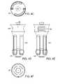
- FIG. 1Ais a schematic side view of a stent including a plurality of holes, in accordance with one embodiment of the invention
- FIG. 1Bis another schematic side view of the stent of FIG. 1A ;
- FIG. 1Cis a schematic rear perspective view of the stent of FIG. 1A , showing the plurality of holes;
- FIG. 1Dis a schematic front perspective view of the stent of FIG. 1A , showing the plurality of holes;
- FIG. 1Eis another schematic rear perspective view of the stent of FIG. 1A ;
- FIG. 1Fis another schematic front perspective view of the stent of FIG. 1A ;
- FIG. 2Ais a schematic plan view of a delivery system for a stent, in accordance with one embodiment of the invention.
- FIG. 2Bis another schematic plan view of the delivery system of FIG. 2A ;
- FIG. 2Cis a photograph of a delivery system inserted in a patient, in accordance with one embodiment of the invention.
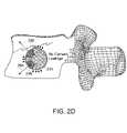
- FIG. 2Dis a schematic side view of a cement filled stent inserted in a vertebral body, in accordance with one embodiment of the invention.
- FIG. 3Ais a schematic plan view of a delivery system and collapsed stent, in accordance with one embodiment of the invention.
- FIG. 3Bis a schematic perspective view of the handle of the delivery system of FIG. 3A ;
- FIG. 3Cis a schematic plan view of the handle of the delivery system of FIG. 3A ;
- FIG. 3Dis a schematic perspective view of the handle of the delivery system of FIG. 3A , with the flexible guidewire (e.g., nitinol wire) retracted;
- the flexible guidewiree.g., nitinol wire
- FIG. 3Eis a schematic perspective view of the handle of the delivery system of FIG. 3A , with the sheath retracted;
- FIG. 3Fis a schematic perspective view of the handle of the delivery system of FIG. 3A , with the flexible guidewire (e.g., nitinol wire) and sheath retracted;
- the flexible guidewiree.g., nitinol wire
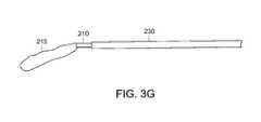
- FIG. 3Gis a schematic perspective view of a stent coupled to the delivery system of FIG. 3A , with the sheath retracted;
- FIG. 3His a schematic perspective view of the handle of the delivery system of FIG. 3A , with the sliding mechanism extended forward;
- FIG. 3Iis a schematic perspective view of the handle of the delivery system of FIG. 3A , with the sliding mechanism retracted to an intermediate position;
- FIG. 3Jis a schematic perspective view of an expanded stent coupled to the delivery system of FIG. 3A ;
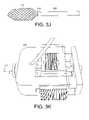
- FIG. 3Kis a schematic perspective view of the handle of the delivery system of FIG. 3A , with the inner core assembly (i.e., polymer extrusion and flexible guidewire) removed;
- the inner core assemblyi.e., polymer extrusion and flexible guidewire
- FIG. 3Lis a schematic perspective view of the handle of the delivery system of FIG. 3A , with a syringe attached;
- FIG. 3Mis a schematic perspective view of the handle of the delivery system of FIG. 3A , with the cement piston inserted to push through additional cement;
- FIG. 3Nis a schematic perspective view of the handle of the delivery system of FIG. 3A , with the cement piston removed;
- FIG. 3Ois a schematic perspective view of the handle of the delivery system of FIG. 3A , with the locking mechanism unlocked;
- FIG. 3Pis a schematic perspective view of the rear of the handle of the delivery system of FIG. 3A , with the locking mechanism unlocked;
- FIG. 4Ais a schematic side view of a handle for a delivery system with a rotational cam mechanism, in accordance with one embodiment of the invention.
- FIG. 4Bis a schematic side view of the handle of FIG. 4A after being turned;
- FIG. 4Cis a schematic end view of another handle for a delivery system with a rotational cam mechanism, in accordance with one embodiment of the invention.
- FIG. 4Dis a schematic side view of the handle of FIG. 4C ;
- FIG. 4Eis a schematic plan view of the handle of FIG. 4C ;
- FIG. 4Fis another schematic end view of the handle of FIG. 4C ;
- FIG. 4Gis a schematic perspective view of a linear sleeve for the handle of FIG. 4C ;
- FIG. 4His a schematic perspective view of a support element on a linear sleeve for the handle of FIG. 4C ;
- FIG. 4Iis a schematic perspective view of the handle of FIG. 4C ;
- FIG. 4Jis another schematic perspective view of the handle of FIG. 4C ;
- FIG. 5is a schematic side view of a handle for a delivery system with a rotational threaded mechanism, in accordance with one embodiment of the invention
- FIG. 6is a schematic side view of a handle for a delivery system with a geared mechanism, in accordance with one embodiment of the invention.
- FIG. 7is a schematic side view of a handle for a delivery system with a sliding belt mechanism, in accordance with one embodiment of the invention.
- FIG. 8Ais a schematic perspective view of a handle for a delivery system with a triggering mechanism, in accordance with one embodiment of the invention.
- FIG. 8Bis a schematic perspective view of the interior cam mechanism of the handle of FIG. 8A ;
- FIG. 9is a schematic perspective view of a delivery system inserted in a cannula, in accordance with one embodiment of the invention.
- FIG. 10Ais a schematic end view of a handle for another delivery system, in accordance with one embodiment of the invention.
- FIG. 10Bis a schematic side view of the handle of FIG. 10A ;
- FIG. 10Cis a schematic plan view of the handle of FIG. 10A ;
- FIG. 11Ais a schematic perspective view of the handle of FIG. 10A ;
- FIG. 11Bis a schematic perspective view of the handle of FIG. 11A after rotation of a rotating user control mechanism
- FIG. 11Cis a schematic perspective view of the handle of FIG. 11B after removal of the top cap;
- FIG. 11Dis a schematic perspective view of the handle of FIG. 11C after depression of sliding of the stent release buttons;
- FIG. 12Ais a schematic sectional side view side view of a releasable attachment mechanism attached at a distal end of a collapsed stent, in accordance with one embodiment of the invention
- FIG. 12Bis a schematic sectional side view of the releasable attachment mechanism of FIG. 12A after expansion of the stent;
- FIG. 12Cis a schematic sectional side view of the releasable attachment mechanism of FIG. 12A after detachment from the distal end of the stent.
- FIG. 12Dis a schematic sectional side view of the releasable attachment mechanism of FIG. 12A injecting filler material into the stent after removal of the inner rod.
- the present inventiondiscloses methods and apparatus for introducing a stent into a curvilinear or other shaped cavity created within the cancellous bone of a fractured vertebral body or other bony structure.
- the inventionalso discloses methods and apparatus for injecting cement into the stent and into the surrounding cancellous bone through positioned exit holes in the stent.
- the methods and apparatus disclosed hereinallow for a covered stent to be safely inserted into the vertebral body through the same entry profile as current vertebral compression fracture treatments. Once in place, the delivery apparatus can direct cement into the stent and through the designated holes into the vertebral body. This can allow for the controlled flow of cement away from the spinal canal and towards the anterior side of the vertebral body. Unlike cardiovascular stent delivery systems, the delivery systems disclosed herein have a positive attachment to the stent for cement injection and stent placement adjustability, thus increasing the stability, controllability, and safety of the system during surgical procedures.
- expansion of a stent in response to retraction of an outer sheath covering the stent, and maintaining it in a collapsed configurationis performed in an orthopedic rather than cardiovascular environment.
- the delivery systemmay have certain features that exhibit some similarity to cardiovascular and endoscopic medical device designs, but may also have several mechanical additions specially designed and configured for orthopedic compatibility.
- the delivery systemis configured to compensate for stent foreshortening in a closed cavity environment. Foreshortening of a stent occurs when a stent is expanded from a radially collapsed configuration to a radially expanded configuration, with the expansion resulting in a reduction in length as the diameter of the stent is increased. This length reduction results in the expanded stent being retracted back from the distal wall of the cavity in which it is deployed, which in turn results in the expanded stent failing to completely fill the cavity in which it is deployed.
- the delivery systems disclosed hereintherefore differ from the usual stent delivery systems that are used in vascular or duct environments where longitudinal space is available to allow foreshortening.
- the stentcan be attached to the distal tip of the delivery system and is not automatically released from the device during stent expansion.
- physiciansare able to pull the stent out of the vertebral body during the surgical procedure, compress, recover with the outer sheath and redeliver the stent if the physician is not satisfied with the original placement. This recovery and redeployment can greatly increase the chances of correctly placing the stent in the most advantageous, and safe, position within a patient.
- the delivery systemhas the ability to retract an outer sheath maintaining the stent in a collapsed configuration from a side portal in order to minimize the length of the delivery system.
- Cement injection back pressuressignificantly increase with longer cement injection channels.
- the overall delivery system lengthcan be reduced. This allows the cement to travel a shorter distance to fill the stent, and therefore reduces the injection pressure required to inject cement into the stent at substantially zero pressure. This reduction in injection pressure can increase the usability of the delivery system, while reducing the potential for failure of the injection process, and increasing the safety of the system.
- the method of cement injection through the delivery systems disclosed hereinmay provide a safer and more efficient means of treating a vertebral compression fracture than current vertebral compression fracture treatments.
- cementmay be initially injected by a syringe through the inner shaft of the delivery system.
- the delivery systemcan direct the cement straight into the stent and through the designated outlet holes in the stent into the surrounding cancellous bone.
- a solid pistoncan be inserted into the inner shaft to deliver more cement.
- the inner lumen of the delivery systemcan, in one embodiment, hold approximately 1.5 cc of cement from the proximal to the distal end.
- the cement pistoncan also be used to completely clear the inner shaft of cement to prevent cement back flow out of the pedical.
- cement injectionbecomes more controlled than in more traditional techniques of vertebroplasty and kyphoplasty.
- a stentin one embodiment, can include a multifilament co-braided shaped structure and a self-expanding structure composite which is collapsible to an elongated tubular shape suitable to fit within a tubular sheath assembled to a novel delivery catheter.
- the outer wall of the stentcan be impregnated in preferred regions with a polymer to form a thicker, relatively less permeable wall.
- the polymer impregnated co-braided wallis further perforated with holes or slots in preferred locations.
- the stent geometryis optimized to fit within a reamed or balloon-expanded cavity located approximately within the anterior 2 ⁇ 3 of a vertebral body.
- the cavityis formed by a sequential method using a number of specifically designed instruments.
- An example stent 100is shown in FIGS. 1A-1F .
- the stent 100can be sized to substantially conform to the dimensions of a predetermined cavity created within a vertebral body.
- the stent 100can be configured to be collapsible, thus allowing delivery of the stent 100 through a relatively small diameter access cannula.
- the stent 100can also have a self-restoring shape, allowing the stent to automatically expand to its original shape, corresponding substantially with the dimensions of the cavity into which it is inserted, without the need for inflation of the stent 100 by the injection of filler material or other fluids or substances.
- the stent 100may be self-restoring to an expanded configuration, at least because it is constructed, at least in part, from a shape-memory material, such as, but not limited to, nitinol.
- the stent 100may be constructed, at least in part, as a braided structure 110 .
- expansion of the stent 100does not generate a distraction force on the end plates of the vertebral body and does not compact the interior cancellous bone structure of the vertebral body.
- filler materialsuch as bone cement
- the injection of filler materialdoes not substantially alter the shape and dimensions of the stent 100 , other than to conform the stent, if necessary, to the shape of the cavity in which it is disposed.
- the wall of the stentmay include at least one hole 120 or permeable region allowing filler material to leave the interior of the stent 100 and enter the vertebral body.
- the at least one hole 120 or porous regioncan allow for the controlled and directed distribution of filler material within the vertebral body.
- the wall of the stent 100may include a plurality of holes of various sizes and/or a plurality of regions of differing permeability, allowing for a greater or lesser escape of filler material in different directions.
- the wall of the stent 100may also include at least one baffle or other non-permeable region preventing the escape of filler material in certain directions. In general, the total cross-sectional area of the holes exceeds that of a cement inlet hole 140 , to prevent excess back pressure or buildup of pressure in the interior of the stent.
- the stent 100may have a proximal region 130 that is configured to be releasably mounted to a delivery system and includes the inlet hole 140 to allow for the injection of cement.
- the stent 100can also have a closed distal region 150 to be positioned away from the delivery system and to be placed against the distal end of the cavity in which it is placed.
- the method of treating the patientmay involve external reduction by extension, i.e. physical manipulation of the patient when placing the patient on the operating table before treatment of the vertebral fracture site.
- the method of treating the patientcan also involve stabilizing the vertebral body, not distracting the upper and lower end plates using the stent as an expansion device.
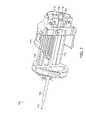
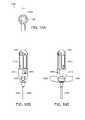
- the delivery system 200can include a handle portion 205 at a proximal end, and a hollow elongate shaft 210 extending towards a distal end.
- a stent 215can be releasably held at the distal end of the hollow elongate shaft 210 .
- the delivery system 200can be configured to releasably couple to a cannula that is inserted percutaneously from the posterior approach through the outer tissue of a patient and anchored into the bone of the vertebral body to a suitable depth.
- the hollow elongate shaft 210can be configured to slidably extend through the cannula such that the stent 215 protrudes from the distal end of the cannula and into a curvilinear cavity formed within the vertebral body.
- the stentmay be configured to extend at a specific angle, or along a predetermined arc, to conform to the axis of the cavity. In an alternative embodiment, the stent may extend straight out from the distal end of the hollow elongate shaft 210 .
- the flexibility and resiliency of the stentis well adapted for use in cavities having a variety of shapes, including curvilinear, cylindrical, tapered, conical, etc.
- the stentmay be flexible, such that it may be deflected by the walls of the cavity and therefore conform substantially to the curvature or shape of the cavity when inserted.
- the cavitymay extend straight out from the distal end of the cannula, and no curvature or deflection of the stent is required for correct insertion of the stent into the cavity.
- a flange 220 and key 225may be fitted to the handle portion 205 of the delivery system 200 at the proximal end of the hollow elongate shaft 210 .
- the flange 220may enable the delivery system to be releasably locked to the cannula to ensure stability of the delivery system 200 during the procedure.
- the key 225may be configured to mate with a slot in the cannula to ensure that the delivery system 200 is inserted into the cannula in the correct circumferential orientation.
- the delivery system 200may include a locking mechanism, latch, or other appropriate means of releasable engagement with the cannula. In a further alternative embodiment, no means of locking the delivery system 200 to the cannula may be required.
- a sheath 230may be used to releasably maintain the stent 215 in a collapsed configuration during insertion through the cannula and into the cavity.
- the collapsed configurationmay be substantially the same diameter as the diameter of the hollow elongate shaft 210 (i.e. a diameter configured to fit slidably through the cannula).
- the sheath 230may be a hollow elongate flexible tube of plastic, fabric, wire mesh, composite, metal or other appropriate material, that can slideably extend over the hollow elongate shaft 210 and stent 215 to hold the stent 215 at a set diameter substantially equal to the diameter of the hollow elongate shaft 210 .
- the proximal end 235 of the sheath 230may extend through an exit hole 240 in the handle 205 of the delivery system 200 .
- An elongate slotmay be inserted in a portion of the proximal end 235 of the sheath 230 to allow the sheath 230 to be pulled out through the exit hole 240 without tearing.
- a handlemay be placed on the end of the sheath 230 to assist in pulling the sheath 230 out through the exit hole 240 .
- the sheath 230is slid over the hollow elongate shaft 210 and stent 215 to hold the stent 215 in a collapsed configuration.
- the sheath 230can be pulled back through the exit hole 240 in the handle 205 . This retracts the sheath 230 back along the hollow elongate shaft 210 and off the stent 215 .
- the stent 215is then free to self-expand to its original shape, which may, in one embodiment, conform substantially with the shape of the curvilinear cavity.
- a marking 245may be placed on the sheath 230 near the proximal end 235 to indicate to a user when the sheath 230 has been retracted far enough to uncover the stent 215 .
- a polymer extrusion and/or a flexible guidewire 250may be inserted through the handle 205 and hollow elongate shaft 210 to provide an internal force to extend the distal end of the stent 215 and assist in holding the stent 215 in a collapsed, or partially collapsed, configuration.
- the polymer extrusionmay be an elongated hollow polymer shaft made of any flexible polymer such as PEBAX, Nylon PET or PTFE.
- the flexible guidewire 250may be an elongate solid or hollow rod of stainless steel, aluminum, plastic, or another appropriate material, that may slideably extend through the hollow elongate shaft 210 of the delivery system 200 , with the distal end of the flexible guidewire 250 abutting against the interior distal end of the stent 215 to force the stent forward.
- the flexible guidewire 250may also include a guidewire handle 255 that can assist the user in pulling and pushing on the guidewire 250 as required.
- a mounting element 260may be releasably connected to the end of the handle 205 with a bayonet retention feature or other attachment feature and through which the flexible guidewire 250 passes.
- the mounting element 260may also be connected to the polymer extrusion that extends down to the stent 215 and is disposed coaxially between the flexible guidewire 250 and the hollow elongate shaft 210 of the delivery system 200 . This extrusion may be used, for example, to provide a smooth, low friction boundary between the guidewire 250 and the hollow elongate shaft 210 .
- the polymer extrusionmay be of a length such that the extrusion also assists in maintaining the stent 215 in a collapsed configuration prior to insertion and deployment in the cavity.
- the mounting element 260may be used to cover a luer lock, or other mounting feature, that may be used to releasably hold a syringe once the inner core assembly (i.e., polymer extrusion and guidewire 250 ) has been removed.
- the inner core assemblymay provide multiple functions for the delivery system 200 .
- the inner core assemblyi.e., polymer extrusion and guidewire 250
- the inner core assemblyi.e., polymer extrusion and guidewire 250
- a sliding mechanism 265can also be used to counteract foreshortening of the stent 215 as a result of expansion within the cavity.
- the sliding mechanismmay be fixedly coupled to the hollow elongate shaft 210 of the delivery system 200 , and be slidably coupled to the handle 205 of the delivery system 200 .
- By sliding the sliding element 265 forwardthe entire hollow elongate shaft 210 and attached stent 215 can be pushed forward, thus pushing the distal end of the expanded stent 215 towards the distal end of the cavity.
- the sliding element 265can be slid backwards by a small amount to counteract any foreshortening of the proximal end of the stent 215 that may result from the pushing process.
- a releasable locking mechanism 270including a spring mounted locking element 275 , can be used to ensure that the sliding element 265 is locked in place when not needed.
- markingsmay be placed on the handle 205 to indicate the length of travel of the sliding element 265 .
- the stent 215may be filled with cement, cement analogue, or other filler material, by fitting a syringe to the luer lock, or other locking mechanism at the proximal end of the hollow elongate shaft 210 , after the inner core assembly (i.e., polymer extrusion and guidewire 250 ) has been removed.
- the cementcan then flow through the hollow elongate shaft 210 and into the interior of the stent 215 , after which it can flow into the vertebral body through the carefully positioned holes in the stent 215 .
- a locking mechanism 280may be included in the handle 205 of the delivery system 200 to releasably hold the stent 215 to the hollow elongate shaft 210 .
- the locking mechanism 280may be attached to an elongate element that is attached at its distal end to the proximate end of the stent 215 .
- the locking mechanism 280may also include a slider 285 , or a switch, clasp, or other user interface element, to unlock the stent 215 from the elongate element and/or hollow elongate shaft 210 once the stent has been correctly positioned and filled.
- a pin 290may be removably inserted into the locking mechanism 280 to ensure that the stent 215 is not released accidentally.
- medical imaging techniquessuch as fluoroscopy, may be used to image the interior of the vertebral body and confirm the location and status of the stent 215 , cement, and cavity.
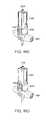
- FIG. 2BAn example a delivery system 200 with the sheath 230 retracted and the stent 215 expended is shown in FIG. 2B .
- FIG. 2CAn example of this delivery system 200 inserted into a patient can be seen in FIG. 2C .
- FIG. 2DA cross-section of a cement filled stent 215 inserted into a vertebral body 292 is shown in FIG. 2D .
- large arrows 294indicate the direction of the cement leaving through holes 296 in the stent 215 in order to stabilize a fracture 298 .
- Small arrowscorrespond to areas of lower permeability of the stent 215 , through which nominal amounts of cement leave the stent 215 to further anchor the stent 215 and fill any remaining voids in the cavity.
- An embodiment of the inventioncan include a method of using the delivery systems described herein to insert and deploy a stent device into a cavity created in a vertebral body.
- the cavitymay be a curvilinear cavity.
- the cavitymay be of any appropriate size and shape, with a stent selected to be configured to substantially conform to the size and shape of the cavity created.
- a procedure for using the devices disclosed hereincan be used to produce a curvilinear cavity within a vertebral body, and place a stent within the cavity created within the vertebral body.
- the stentcan be a self-expanding, covered stent that allows interdigitation and prevents leakage of bone cement in undesired directions.
- a single stentcan be placed at a mid-line location of a vertebral body, rather than placing multiple stents on either side of the mid-line, thus reducing the time and fluoroscopy exposure require during a surgical implantation procedure.
- the method of creating a cavity for within a vertebral body, or other bony bodycan include first creating a posterior pathway to the vertebral body, using a extrapedicular or intrapedicular approach, with a Jamshidi needle and/or K-wire. This may be performed, for example, using a dual C-arm technique to place and medialize the Jamshidi needle/K-wire to the fullest extent.
- a working channel and trocar assemblycan then be inserted along the pathway created by the Jamshidi needle/K-wire. This can be performed, for example, by locking the trocar into the working channel, inserting the working channel into the pathway, and tapping the assembly into place until the distal tip of the trocar and working channel extends, in one embodiment, 1-3 mm beyond the posterior wall of the vertebral body. The trocar can then be removed, leaving the open working channel in place.
- a curved pathway through the vertebral bodycan then be created using a curved drill. This may be achieved using any of the drill arrangements described herein.
- the drill depth markings at the user interfaceare set to “0”mm prior to insertion into the working channel.
- the drillcan then be locked into the working channel with the key facing in the medial direction, thus ensuring the correct direction of curvature of the drill within the vertebral body.
- the handle of the drillcan then be rotated to advance the drill tip into the vertebral body, with fluoroscopy, or some other appropriate technique, used to determine when the desired depth of penetration is achieved.
- the drillcan then be removed and the depth markings on the user interface recorded.
- the drill tipis oriented in the contralateral anterior quadrant of the vertebral body, thus assuring proper cavity positioning and bilateral cement filling.
- a larger cavitycan then be created within the vertebral body by reaming out the hole created by the curved drill with a curved reamer.
- Thismay be achieved, for example, by first setting the depth markings on the user interface of the reamer to match those recorded for the drill depth, thus assuring that the reamer is positioned correctly within the vertebral body.
- the reamercan then be advanced fully into the pathway created by the drill and locked into the working channel, with the position of the reamer confirmed using fluoroscopy or some other appropriate technique.
- the blade of the reamercan then be opened, for example by rotating a portion of the handle of the reamer, and reaming can be carried out by rotating the handle.
- the reamermay be stopped approximately 1-3mm before approaching the distal tip of the working channel, with the position confirmed by fluoroscopy, or some other appropriate technique.
- the bladecan then be closed (for example by rotating a portion of the handle in the opposite direction), and the reamer removed.
- the cavity created by the reamercan have a slight taper from the distal end to the proximal end.
- a stent delivery systemcan be locked into the working channel to correctly position a stent within the vertebral body.
- a sheath covering the stentcan be removed to deploy and expand the stent, and cement can be injected into the stent by attaching a syringe to the proximal end of the delivery system.
- the desired amount of cementcan be injected into the stent with fluoroscopy, or some other appropriate technique, being used to monitor the flow of cement into the stent.
- the stentcan be released from the delivery system and the delivery system removed from the working channel, thus leaving the stent in place within the vertebral body.
- the working channelcan then be removed and the access pathway sutured or otherwise closed.
- One example embodimentmay include inserting a delivery system 200 into the cannula such that the covered stent is extended beyond the distal end of the cavity and into the curvilinear cavity.
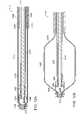
- a delivery system prior to insertion into a cannulais shown in FIGS. 3A-3C .
- the delivery system 200can engage with, and be locked in place by, a locking element associated with the cannula.
- the delivery system 200may be extended through the cannula until a user can feel resistance to the forward movement, indicating that the end of the collapsed stent is abutting against the distal end of the cavity created within the vertebral body.
- the length of the cavitymay be carefully measured such that the end of the collapsed stent will automatically extend to the end of the cavity upon insertion of the delivery system 200 .
- representative fluoroscopic photos or movies, or use of other appropriate medical imaging techniquesmay be taken to ensure the correct placement of the stent within the cavity.
- the inner core assemblyi.e., polymer extrusion and guidewire 250
- the inner core assemblyi.e., polymer extrusion and guidewire 250
- the flexible guidewire 250 and handle 255may be pulled back by approximately two inches, or by a greater or lesser distance, as required.
- the flexible guidewire 250 and handle 255may be removed completely.
- An example of a flexible guidewire 250 and handle 255 being retractedcan be seen in FIG. 3D .
- Expansion of the stentcan be executed by retracting the sheath 230 , for example by pulling on a handle attached to the sheath, by a predetermined amount.
- a mark 245may be placed on the sheath 230 to indicate when the sheath 230 has been pulled back by the correct amount. Retracting the sheath 230 removes the external restrictive force on the stent and allows it to self-expend to its preformed, free-state configuration. This may, in one embodiment of the invention, substantially conform to the size and shape of the cavity.
- FIGS. 3E and 3FAn example of a sheath 230 after being retracted can be seen in FIGS. 3E and 3F .
- the sheath 230can be removed prior to the polymer extrusion being removed.
- An example of a stent 215 with the sheath 230 retracted but with the polymer extrusion remaining in place and extended to the distal end of the stent 215can be seen in FIG. 3G .
- expansion of the stent 215can also result in a certain amount of foreshortening at the distal end of the stent 215 .
- This foreshorteningwhich is caused by the increase in the diameter of the stent 215 as it expands resulting in a responsive decrease in the length of the stent 215 , may retract the end of the stent 215 slightly from the distal end of the cavity. This may be compensated for by providing a force to push the entire stent 215 forward until the distal end of the expanded stent 215 abuts against the distal end of the cavity.
- a sliding mechanism 265that is configured to allow for the extension and retraction of the entire stent 215 and elongated shaft 210 arrangement along the axis of the shaft.
- the stent 215 and elongated shaft 210can be pushed forward by the required amount.
- the sliding mechanism 265can then re-engage the locking mechanism to lock the stent at a final position.
- An example of the sliding mechanism 265 pushed forward within the handle 205can be seen in FIG. 3H .
- forcing the expanded stent 215 forwardmay result a certain amount of foreshortening of the stent 215 at its proximal end (i.e. the end attached to the elongated shaft 210 of the delivery system 200 ).
- the sliding mechanism 265may be retracted by a small amount to counteract any foreshortening at the proximal end of the stent 215 .
- the sliding mechanism 265may be locked into position once the stent 215 has been correctly positioned.
- fluoroscopic images, or other appropriate medical imagesmay be taken to confirm the positioning and expansion of the stent at the distal end of the cavity.
- the polymer extrusionmay also be used to extend the expanded stent after foreshortening due to the expansion.
- An example of the sliding mechanism 265 retracted after being pushed forward within the handle 205can be seen in FIG. 3I .
- An example of a fully expanded stent 215 coupled to a hollow elongated shaft 210 with a sheath 230 retractedcan be seen in FIG. 3J .
- the polymer extrusioncan perform the function of collapsing the stent by stretching the stent out longitudinally or axially, by applying a force in that direction from within the stent.
- the proximal end of the stentis fixed to the elongate shaft 210 and the distal end of the stent is stretched and held in place by the polymer extrusion which is locked in position to the handle 205 by the mounting element 260 .
- With the stent collapsedit can be moved easily down the working channel, thereby eliminating the need for a sheath in the delivery system.
- the polymer extrusioncan be removed completely from the delivery system 200 by releasing and retracting the mounting element 260 from the handle portion 205 . Removing the polymer extrusion leaves a hollow shaft 210 through the center of the delivery system 200 and into the interior of the expanded stent 215 . This hollow shaft can then be used for the injection of cement, or other material, into the stent.
- An example of the delivery system with the polymer extrusion removedcan be seen in FIG. 3K .
- Injection of cement into the stentmay be performed by releasably connecting the end of a syringe 310 to the hollow shaft at the point vacated by the polymer extrusion mounting element 260 .
- a 10 cc threaded syringemay be used, although in alternative embodiments, any appropriate injection device may be utilized.
- the proximal end of the hollow shaftmay include a luer lock 320 , or other releasable locking arrangement, that may engage the end of the syringe 310 and engage it with the hollow shaft 210 .
- An example of a syringe 310 attached to the handle 205 of the delivery system 200can be seen in FIG. 3L .
- a rigid or flexible extension tubecan be interdisposed between the syringe 310 and the handle 205 .
- the extension tubeallows the physician to have his hands out of the fluoroscopic field and also provides the opportunity to reorient the syringe 310 , e.g., by forming an “elbow” or other angular connection, so that the syringe 310 is not fixedly cantilevered axially from the delivery system 200 .
- the cement, or other material, such as a cement analoguecan be injected into the hollow shaft 210 of the delivery system 200 and into the expanded stent 215 . Injection of cement may be continued until the stent 215 is completely filled and cement flows out of the designated holes in the stent into the vertebral body. Once enough cement has flowed out of the stent 215 and into the vertebral body to provide the required level of interdigitation between the stent 215 and vertebral body, the injection can be stopped. Again, fluoroscopic images, or other appropriate medical images, may be taken to confirm that the stent has been filled and the required amount of cement has flowed out into the vertebral body at the correct positions.
- a cement piston 325may be used to push additional cement in the hollow shaft 210 into the stent 215 , for example when high cement viscosity has resulted in incomplete filling of the cavity. This may be achieved by simply detaching the syringe 310 , and pushing the cement piston 325 back into the hollow shaft 210 to force the additional cement in the shaft 210 into the stent 215 . This may be important if the physician is not satisfied with the amount of cement filling prior to removal.
- the hollow shaft 210can hold 1.5 cc of cement, or other material, with the cement piston 325 capable of pushing any percentage of that volume into the stent 215 , as required.
- the cement piston 325can again be removed.
- An example of the cement piston 325 forcing cement through the shaft 210can be seen in FIG. 3M .
- An example of the handle 205 of the delivery system 200 , after the cement piston 325 has been removed again,can be seen in FIG. 3N .
- a locking mechanism 280may be used to hold the stent 215 onto the delivery system 200 .
- This locking mechanism 280may include any appropriate means of releasably engaging the proximal end of the stent, including, but not limited to, a clamping mechanism, a grasping mechanism, sliding mechanism, a pressure fit between an outer shaft, the proximal end of the stent, and the inner hollow shaft, or any other appropriate mechanism.
- the locking element 285may include a slide, switch, or other element at the proximal end of the delivery system, allowing the locking mechanism to disengage from the stent when required.
- a removable pin 290or other locking device, may be inserted into the delivery system 200 to ensure that the delivery system 200 is not disengaged from the stent 215 inadvertently, before the cement has been fully injected.
- An example of the locking mechanism 280 after the pin 290 has been removed and the locking mechanism 280 openedis shown in FIGS. 3O and 3P .
- the delivery systemcan be unlocked and removed from the cannula. After this, the cannula may be removed and the surgical incision closed.
- a delivery systemincluding a handle adapted to move multiple components of the delivery system with a movement of a single user control mechanism can be used to deploy a stent within a cavity created within a vertebral body.
- This user control mechanismcan include a mechanism such as, but not limited to, a rotating mechanism, a sliding mechanism, a trigger mechanism, or any other appropriate mechanical, electrical, and/or magnetic mechanism.
- a user control mechanismcan control the retraction of a sheath covering the stent, the movement of an inner shaft, and/or the movement of an outer shaft.
- the inner shaftcan include, but is not limited to, a flexible guidewire, a hollow flexible shaft, and/or another appropriate elongate element configured to extend through the interior of an outer shaft.
- the outer shaftcan include, but is not limited to, a hollow elongate shaft configured to releasably engage the stent at its distal end.
- additional and/or different functions of the delivery systemcan be controlled by a single user control mechanism. These functions can include, but are not limited to, injecting filler material such as cement into the stent, releasing the stent, locking, and/or unlocking, the delivery system to/from the cannula, curving the distal end of the flexible shaft to facilitate deployment of the stent within a curved cavity, and/or any other appropriate function of a stent delivery system.
- a user control mechanismis adapted to retract the outer sheath of the elongate shaft of a delivery system to allow the stent to be fully deployed within a cavity in a vertebral body.
- the inner and outer shafts of the elongate shaftare moved forward to compensate for any foreshortening of the stent during retraction of the sheath, as described above. This allows the stent to be deployed in its expanded configuration at the full distal extent of the cavity.
- the user control mechanismcan be configured to move the sheath and the inner and outer shafts simultaneously in opposite directions by set amounts, with the sheath being retracted towards the handle of the delivery system while the inner and outer shafts are extended outwards away from the handle.
- each of the sheath and the inner and outer shaft should be moved relative to each otheris dependent upon factors that can include the size and shape of the stent and the cavity in which the stent is being deployed.
- the sheathcan be retracted by a distance equal to or greater than the length of the stent to ensure that it is fully retracted from the stent in order to allow the stent to expand fully.
- the inner and outer shaftsin contrast, can be extended by a distance equal to the foreshortening of the stent as it expands from its collapsed configuration to its expanded configuration.
- the inner and outer shaftscan be extended out from the handle by the same distance. In an alternative embodiment, the inner shaft and the outer shaft can be extended out from the handle by different distances.
- Example user control mechanisms for moving multiple components of a delivery systemcan be seen in FIGS. 4A-8B .
- FIGS. 4A and 4Bshow a handle 400 for a delivery system with a rotational cam mechanism 410 before and after being rotated.
- the rotational cam mechanism 410includes three separate slotted cam shafts wrapped helically on a support element 420 surrounding the central shaft 425 of the handle 400 .
- An outer grip 430covers the support element 420 and central shaft 425 and engages with the support element 420 .
- Pins associated with each of the outer shaft, the inner shaft, and the sheathengage with the slotted cam shafts such that a rotation 435 of the support element 420 will force the pins axially along the central shaft of the delivery device in a direction and distance controlled by the angle and direction of each slotted cam shaft.
- a first slotted cam shaft 440engages with a first pin 445 attached to the outer shaft of a delivery system.
- a second slotted cam shaft 450engages with a second pin 455 attached to the inner shaft of the delivery system.
- a third slotted cam shaft 460engages with a third pin 465 attached to a sheath.
- the third pin 465will be pulled axially rearwards 475 toward the proximal end of the handle 400 , resulting in the sheath being pulled rearwards 475 towards the handle 400 (and therefore exposing the stent).
- the helical paths for each of the inner shaft and outer shafthave the same angle, resulting in the distal ends of the inner shaft and outer shaft each being forced forward 470 the same distance.
- the helix paths for each of the inner shaft and outer shaftmay be different, resulting in the distal ends of the inner shaft and outer shaft being forced forward 470 by a different amount.
- at least one of the inner shaft and outer shaftmay be stationary.
- Additional axially slotted cam shaftscan be located at the distal end of the first slotted cam shaft 440 and third slotted cam shaft 460 , allowing the first pin 445 and third pin 465 to remain in the same axial position while the second pin 455 is moved rearwards 475 by pulling the outer grip 430 rearwards 475 towards the proximal end of the handle 400 of the delivery system after the rotation of the outer grip is completed.
- the pinscan be moved axially by different distances when the outer grip is pulled rearwards 475 towards the proximal end of the handle.
- the first axial slotted cam shaft 480(associated with the outer shaft) is shorter than the second axial slotted cam shaft 485 (associated with the sheath), so that when the outer grip 430 is pulled rearwards 475 , the second pin 455 is moved rearwards 475 along with the outer grip 430 , the first pin 445 remains stationary until it connects with the end 490 of the first axial slotted cam shaft 480 , after which it moves rearwards 475 along with the outer grip 430 , and the third pin 465 remains stationary throughout the entire axial rearward 475 motion of the outer grip 430 .
- different lengths of axial cam shaftscan be associated with any of the pins, allowing for different rearward travel distances, as desired.
- the stentBy moving the outer shaft back a certain distance after being pushed forward, while leaving the inner shaft extended, the stent can be stretched out and fully deployed without the distal end of the stent being pulled back from the distal end of the cavity.
- the outer grip 430can be rotated through approximately 120° to fully move the sheath, inner shaft, and outer shaft (and thus deploy the stent). In an alternative embodiment, a larger or smaller rotation of the outer grip 430 , for example between 90° and 360°, can be used.
- the delivery systemincludes a handle portion 400 and a hollow elongate shaft (not shown) extending from the distal end of the handle 400 .
- the hollow elongate shaftcan include a distal end adapted to support and deploy a stent within a cavity created within a vertebral body.
- the hollow elongate shaftcan include an inner shaft and an outer shaft adapted to engage a stent, releasably positioned at the distal end of the elongate shaft.
- a sheathcan be positioned over the outer shaft and extend over the stent to maintain the stent in a collapsed configuration during insertion through the cannula and into the cavity.
- the rotational cam mechanism 410includes three separate slotted cam shafts wrapped helically on a support element 420 surrounding the central shaft 425 of the handle 400 .
- An outer grip 430covers the support element 420 and central shaft 425 and engages with the support element 420 .
- Pins 445 , 455 , 465(associated with each of the outer shaft, the inner shaft, and the sheath) engage with the slotted cam shafts 440 , 450 , 460 such that a rotation 435 of the support element 420 will force the pins 445 , 455 , 465 axially along the central shaft of the delivery device in a direct and distance controlled by the angle and direction of each slotted cam shaft 440 , 450 , 460 .
- the pins 445 , 455 , 465are positioned within a linear support sleeve 492 that is configured to ensure that the pins 445 , 455 , 465 can only move axially, either forwards 470 or backwards 475 , along the length of the handle 400 .
- a schematic perspective view of the linear support sleeve 492 engaging one of the pinsis shown in FIG. 4G , with FIG. 4H showing the support element 420 positioned on the linear support sleeve 492 .
- a single axial slotted cam shaft 495is located at the distal end of the first slotted cam shaft 440 and third slotted cam shaft 460 , allowing the first pin 445 and third pin 465 to moved rearwards 475 together.
- a removable cap 497is placed on the proximal end of the handle 400 to cover a luer lock 498 adapted for engagement with a filler material delivery device, such a syringe.
- a stent release button 482is located on the handle 400 to actuate disengagement of the stent from the elongate shaft once deployment and filling of the stent is completed.
- the stent release button 482can be depressed and slid rearwards 475 towards the proximal end of the handle 400 (i.e. away from the elongate shaft) to release the stent from the elongate shaft.
- two stent release buttons located opposite each other on either side of the handle 400can be used.
- any appropriate user interface elementsincluding, but not limited to, a dial, a switch, a sliding element, or a button, can be used to activate the detachment of the stent from the elongate shaft, and/or to perform any other required functions.
- FIG. 5shows a handle 500 for a delivery system with a rotational threaded mechanism 510 .
- the rotational cam mechanism 510includes two separate threads wrapped helically on a support element 520 surrounding the central shaft 525 of the handle 500 .
- An outer grip 530covers the support element 520 and central shaft 525 and engages with the threads on the support element 520 .
- a first thread 540is associated with the sheath of the delivery system, while a second thread 550 is associated with at least one of the inner shaft and outer shaft of the delivery system.
- a slotted control button 560can provide a user control for additional functions of the delivery system.
- a rotation of the outer grip 530will drive the sheath (associated with the first thread 540 ) in an axially rearward 575 direction, while the inner and/or outer shaft (associated with the second thread 550 ) will be driven in an axially forward 570 direction.
- the helical angle of each threadwill determine how far each element is moved axially through the rotation of the outer grip 530 .
- larger or smaller helical anglescan be used to move one or more elements by any required distance, as appropriate.
- more threads, at any required helical anglecan be incorporated into the rotational threaded mechanism 510 to control additional elements of the delivery system.
- a geared mechanismcan be used to control the movement of the inner shaft, the outer shaft, the sheath, and/or any other appropriate element of the delivery system.
- the geared mechanismcan include a number of gear arrangements, including any appropriately configured and sized gears to move the shafts and/or sheath in different directions and by different distances, as required sequentially or simultaneously.
- An example geared mechanism 610can be seen in FIG. 6 .
- FIG. 6shows a handle 600 for a delivery system with a geared mechanism 610 .
- the geared mechanism 610includes a first gear arrangement 620 , engaging the sheath, and a second gear arrangement 630 for controlling the movement of one of more of the inner and outer shafts.
- a pin 640can be moved in a rearward direction 675 by a user, thus pulling the sheath rearwards 475 by a distance corresponding to the length of the slot 650 .
- the first gear arrangement 620will be driven by the movement of the pin 640 , which will in turn drive the second gear arrangement 630 and push the inner shaft and/or outer shaft in a forward direction 670 .
- the sheath and the inner and/or outer shaftscan be moved by any appropriate distance and in either the forward 670 or rearward 675 direction.
- Different gearing arrangements to drive additional and/or different elementscan be used, as appropriate.
- a dial associated with a gearing element, or other appropriate user controlcan be used instead of, or in addition to, the pin.
- FIG. 7shows a handle 700 for a delivery system with a sliding belt mechanism 710 .
- the sliding belt mechanism 710includes a sliding outer grip 720 that is coupled to an inner sliding belt arrangement 730 that forces an inner element 740 in a forward 770 direction as the sliding outer grip 720 is pushed in a rearward 775 direction by a user.
- the sheathis attached to the sliding outer grip 720 , while the inner shaft and outer shaft are connected to the inner element 740 .
- each shaft and sheathcan be moved forwards 770 or rearwards 775 , as required.
- the sliding belt mechanismcan provide simultaneous movement of the shafts and/or sheath, but may also provide sequence in the movement of the shafts and/or sheath by delaying one function through the belt arrangement 730 .
- a luer lock 760can be placed at a proximal end of the handle 700 to provide a coupling element for a cement deliver device, such as a syringe.
- FIGS. 8A and 8Bshow a handle 800 for a delivery system with a triggering mechanism 810 .
- the triggering mechanism 810includes three separate slotted cam shafts positioned on a pair of cam plates 820 within a trigger 825 that is pivotably connected to a support element 830 .
- Pins associated with each of the outer shaft, the inner shaft, and the sheath of the elongate shaft 815engage with the slotted cam shafts such that a closing of the trigger 825 will force the pins axially along the central shaft 835 of the delivery device in a direct and distance controlled by the angle and direction of each slotted cam shaft.
- This configurationcan result in a simple mechanical delivery system that is easy to use.
- a first slotted cam shaft 840engages with a first pin 845 attached to the outer shaft of a delivery system.
- a second slotted cam shaft 850engages with a second pin 855 attached to the inner shaft of the delivery system.
- a third slotted cam shaft 860engages with a third pin 865 attached to a sheath.
- the first pin 845 and second pin 855will be forced axially forward 870 toward the distal end of the handle 800 , resulting in the inner shaft and outer shaft being extended outwards from the distal end of the handle 800 (and therefore compensating for any foreshortening of the stent during deployment).
- the third pin 865will be pulled axially rearwards 875 toward the proximal end of the handle 800 , resulting in the sheath being pulled rearwards 875 towards the handle 800 (and therefore exposing the stent).
- the first slotted cam shaft 840includes a bend 890 , resulting in the first pin 845 (and therefore the outer shaft) being moved forward 870 initially before being moved in a rearward direction 875 during a second portion of the closing motion.
- any one or more of the cam shaftscan be curved, bent, and/or angled in any appropriate manner to produce the required forwards and/or rearward movement of each element of the delivery system.
- none of the cam shaftsinclude a bend.
- a luer lock 895can be placed at a proximal end of the handle 800 to provide a coupling element for a cement delivery device, such as a syringe.
- a bump 892 on a rear portion of one or both of the cam plates 820can engage and force the release of an end cap on the handle 800 , thus exposing the luer lock 895 and prompting the user to begin the next stem of the process.
- no bumpis required, and the end cap of the handle 800 is instead removed manually.
- the delivery systemmay include a locking mechanism adapted to releasably lock the delivery system within a cannula in a required circumferential orientation, to ensure the correct positioning of the stent within the cavity created within the vertebral body.
- a spring loaded locking mechanism on the cannulamay engage a portion of the handle of the delivery system to releasably lock it in place, with one or more buttons, switches, knobs, or other appropriate user elements, either on the cannula or on the handle of the delivery system, releasing the locking mechanism when the delivery system is to be removed.
- the cannulacan include a sliding element adapted to engage a protruding flange at a distal end of a handle of a delivery system to releasably lock the delivery device into the cannula.
- An example cannula 900 including a sliding element 910 for releasably engaging a protruding flange of a delivery system 920can be seen in FIG. 9 .
- any other appropriate means of releasably locking the delivery system to the cannula in a required circumferential configurationcan be used.
- a keymay be positioned on the hollow elongate shaft to mate with a slot in the cannula to ensure that the delivery system is inserted into the cannula in the desired orientation.
- at least a portion of the distal end of the handle of the delivery systemcan be configured to mate with a portion of the cannula, thus ensuring the positioning of the delivery system in the correct orientation.
- the delivery systemcan be used to deploy a stent within a cavity created within a vertebral body, wherein the handle is adapted to control multiple components of the delivery system with a movement of a single user control mechanism, such as a rotation, sliding, or triggering of a user control mechanism.
- FIGS. 10A to 10CAnother example delivery system 1000 , including a rotating user control mechanism 1040 on the handle 1010 , can be seen in FIGS. 10A to 10C .
- the rotating user control mechanismcan include, but is not limited to, a rotational cam mechanism or a rotational threaded mechanism.
- a gear mechanism, a sliding belt or triggering mechanism, or any other appropriate mechanism, as described herein,can be used in place of the rotating user control mechanism 1040 to move the inner shaft, outer shaft, and/or sheath, as required.
- the delivery system 1000includes a handle 1010 , an elongate shaft 1020 , including a key component 1025 , a top cap 1030 , and a number of user interface elements.
- the user interface elementsinclude a rotating user control mechanism 1040 and two stent release buttons 1050 .
- a lesser or greater number of stent release buttonscan be used.
- the stent release buttons 1050can be replaced by one or more switches, knobs, sliding elements and/or other appropriate user elements, or combinations thereof, as required.
- one or more additional user input mechanisms 1060can be incorporated into the handle 1010 .
- These user input mechanisms 1060can include, but are not limited to, delivery system release mechanisms, stent deployment and/or release mechanisms, a mechanism for controlling the curvature of a distal end of one or more of the elongate shafts, or any other appropriate control, delivery, and/or deployment function control elements.
- the user input mechanisms 1060can include, but are not limited to, buttons, switches, dials, sliding elements, or other appropriate mechanical or electrical input elements.
- the user input mechanism 1060is a delivery system release mechanism adapted to allow the delivery system 1000 to be unlocked and disengaged from a cannula or other working channel. Again, any other appropriate user element on the delivery system 1000 and/or cannula can be used to release the delivery system 1000 from the cannula upon completion of the stent deployment.
- FIGS. 11A to 11DA method of using the delivery system 1000 , in accordance with one embodiment of the invention, can be seen in FIGS. 11A to 11D .
- This embodimentincludes first inserting the delivery system 1000 into the cannula and locking it in position in a predetermined set orientation.
- FIG. 11Ashows the delivery system 1000 in its initial configuration after insertion into a cannula (not shown).
- the rotating user control mechanism 1040 on the handle 1010 of the delivery system 1000can then be rotated, resulting in the outer sheath of the elongate shaft being retracted while the inner and outer shafts are moved forward to compensate for any foreshortening of the stent during retraction of the sheath, as described above.
- FIG. 11Bshows the delivery system 1000 after rotation of the rotating user control mechanism 1000 .
- FIG. 11Cshows the handle 1010 with a top cap 1030 removed. Cement can then be injected through the delivery system 1000 and into the stent. Once the required amount of cement has been delivered into the stent, the syringe can be removed.
- the stent release buttons 1050can then be depressed and slid towards the proximal end of the handle 1010 (i.e. away from the elongate shaft 1020 ) to release the stent from the elongate shaft 1020 .
- FIG. 11Dshows the delivery system 1000 with the stent release buttons 1050 depressed and slid towards the proximal end of the handle 1010 to release the stent.
- the delivery system 1000can then be safely removed by activating a delivery system release button, or other appropriate mechanism, to disengage the delivery system 1000 from the locking mechanism on the cannula, and removing the delivery system 1000 from the cannula while leaving the disengaged stent within the vertebral body.
- a distal end of an elongate shaftcan include a preformed curvature.
- the elongate shaftcan include, but is not limited to, an inner shaft, an outer shaft, a tubular sheath, a flexible guidewire, and an internal polymer extrusion.
- the elongate shaft, or a portion thereof,can be constructed from a metal including, but not limited to, nitinol, steel, aluminum, or any other appropriate material such as, but not limited to, a plastic.
- the distal end of the elongate shaftcan also include a slotted arrangement allowing the distal end of the elongate shaft to curve and/or preferentially buckle in a specified direction.
- This curving of the distal end of the elongate shaftcan be controlled by a curvature control mechanism located, for example, within the handle of the delivery system.
- the elongate shaftcan preferentially buckle in response to a force imposed on the distal end of the elongate shaft by the surrounding bone and/or tissue within the vertebral body.
- Example elongate shafts with preformed and controlled curvature and/or preferential bucklingare described in the related U.S. patent application Docket No. SOT-004, entitled “Devices and Methods for Vertebrostenting,” and filed of even date herewith, and U.S. application Ser. No. 11/091,232, the disclosures of which are being incorporated herein by reference in their entirety.
- a stent for use with the apparatus and methods described hereincan include an attachment mechanism at a distal end thereof (i.e. at the end of the stent remote from the elongate shaft).
- This attachment mechanismcan releasably attach to one or more elongate elements extending through the interior of the elongate shaft.
- the elongate element extending through the elongate shaft and attaching to the distal end of the stentcan be used to hold the stent in a collapsed configuration prior to deployment in place of, or in addition to, a sheath.
- the attached elongate elementcan be used to pull the distal end of the stent rearwards towards its proximate end (i.e. the end of the stent releasably attached to the distal end of the elongate shaft) in order to assist in expanding or to forcibly expand the stent.
- a stiffer and/or thicker stentmay benefit from additional external forces to assist in its expansion or to provide positive forces on the walls of a cavity in which it is inserted.
- a stiffer stentwith a more substantive mesh structure, can be used to provide a jacking force to expand the size of a cavity and/or jack or push two walls of a collapsed vertebral body apart.
- the self-expanding nature of the stentmay not provide sufficient force in and of itself to provide a jacking force of desired magnitude.
- the additional force needed to allow the stent to jack the walls apartcan be provided by the pulling force applied to the distal end of the stent by the releasably attached elongate element.
- the elongate elementcan be released from the stent and removed through the elongate shaft.
- the elongate element releasably attached to the distal end of the stentcan also be advantageous in embodiments where a cavity has not been reamed out in the vertebral body, or other structure, but rather only a drill hole has been created in the vertebral body sufficient in size to receive the stent in a collapsed configuration.
- the elongate elementcan be used to pull on the distal end of the stent and assist in expanding it into the body structure surrounding the drill hole. This method may be useful, for example, in the treatment of seriously degraded vertebral bodies, where the stent can be expanded into the surrounding degraded bony structure with nominal additional force.
- FIGS. 12A to 12DAn example stent deployment method including a stent with an attachment mechanism at its distal end can be seen in FIGS. 12A to 12D .
- a stent 1205is releasably attached at its proximal end 1210 to an elongate shaft 1215 including an inner shaft 1220 and an outer shaft 1225 .
- the means of releasably attaching the stent 1205 to the elongate shaftcan include any of the mechanisms and methods described herein.
- a ferrule 1230is placed against the interior wall of the distal end 1235 of the stent 1205 , with a locking ring 1240 holding the ferrule 1230 in place against the wall of the distal end 1235 of the stent 1205 , for example by a radial interference fit.
- the ferruleincludes a hollow proximate end 1245 with two slots 1250 formed in the walls thereof.
- the slots 1250are adapted to releasably engage an elongate attachment element 1255 with a pair of tangs 1260 at a distal end thereof.
- the tangs 1260are bent in towards the central axis 1275 of the elongate attachment element 1255 such that the tips 1265 of the tangs 1260 can be extended into the hollow proximate end 1245 of the ferrule 1230 .
- a greater or lesser number of slots 1250 and corresponding tangs 1260can be used.
- an inner rod 1270is extended through the elongate attachment element 1255 to abut against the inner walls of the tangs 1260 .
- the inner rod 1270pushes the ends of the tangs 1260 outwards from the central axis 1275 of the elongate attachment element 1255 such that the tips 1265 are forced into the slots 1250 in the ferrule 1230 .
- the elongate attachment element 1255becomes releasably coupled to the ferrule 1230 and can therefore provide a pulling force to the distal end 1235 of the stent 1205 .
- the elongate attachment element 1255is coupled to the ferrule 1230 prior to deploying the stent 1205 in the vertebral body.
- the elongate attachment element 1255is pushed forwards against the distal end 1235 of the stent 1205 to force the stent 1205 into a collapsed configuration, as shown in FIG. 12A .
- a sheathcan be extended over the stent 1205 to hold the stent 1205 in a collapsed configuration, with the sheath being retracted once the stent 1205 is in position within the vertebral body, as described above.
- no sheathis required, with the elongate attachment element 1255 providing sufficient force to maintain the stent 1205 in a collapsed configuration.
- the elongate attachment element 1255can be pulled back by a set amount, dependent upon the size and shape of the stent 1205 , thus pulling on the distal end 1235 of the stent 1205 and forcing it to expand to its deployed configuration, as shown in FIG. 12B .
- the proximal end 1210 of the stentcan be advanced or pushed forward, in order to expand the stent 1205 while leaving a midpoint of the stent 1205 in essentially a fixed position in the cavity in the vertebral body.
- This coordinated action of retracting the distal end 1235 while advancing the proximal end 1210can be accomplished using the types of mechanisms described above located in the handle.
- the inner rod 1270can be pulled out from the elongate attachment element 1255 , as shown in FIG. 12C .
- the tangs 1260collapse back into their initial configuration (i.e. bent in towards the central axis 1275 of the elongate attachment element 1255 ). This in turn removes the tips 1265 of the tangs 1260 from the slots 1250 of the ferrule 1230 , thus disengaging the elongate attachment element 1255 from the ferrule 1230 .
- the elongate attachment element 1255can then be pulled out from the ferrule, leaving the distal end 1235 of the stent 1205 free.
- the elongate attachment element 1255is a hollow needle adapted to inject cement into the stent 1205 .
- cementcan be injected through the elongate attachment element 1255 and into the interior of the stent 1205 to fill the stent 1205 , as shown in FIG. 12D .
- the elongate attachment element 1255can be removed and the stent 1205 detached from the elongate shaft.
- the elongate attachment element 1255can simply be removed from the elongate shaft 1215 after deployment of the stent 1205 , with cement, or any other appropriate filler material, being injected thereafter into the stent 1205 directly through the inner shaft 1220 of the elongate shaft 1215 , or through a separate cement injection element.
- the elongate attachment element 1255 , elongate shaft 1215 , ferrule 1230 , locking ring 1240 , and inner rod 1270can be constructed from materials including, but not limited to, a metal (e.g. nitinol, steel, aluminum, or any other appropriate metal), a plastic, and/or a composite material.
- a metale.g. nitinol, steel, aluminum, or any other appropriate metal
- plastice.g. nitinol, steel, aluminum, or any other appropriate metal
- the ferrule 1230can be attached to the distal end 1235 of the stent 1205 by any other appropriate method, such as, but not limited to, being glued to, welded to, or otherwise attached to the stent 1205 .
- the elongate attachment element 1255can be releasably attached to the ferrule by any appropriate mechanical, electrical, thermal, or magnetic connection means.
- any appropriate material, or combination of materialsmay be used for the components of the delivery system.
- Appropriate materialsinclude, but are not limited to, stainless steel, aluminum, plastics, textiles (for the sheath), composite materials, or any combination thereof.
- the delivery systemmay be configured with all, or only some of, the components described herein, depending upon the specific requirements of the system.
- the delivery systemmay be configured to deliver cement, cement analogue, or other appropriate filler material, to any appropriate stent, bag, or other fillable device.
- the stentneed not have holes for the directed exit of the cement into the vertebral body.
- the delivery systemmay be configured to delivery a stent, or other device, to a cavity in any bony structure, and not just a vertebral body. Additionally, any appropriately shaped cavity may be treated with the above-mentioned delivery system and stents.
Landscapes
- Health & Medical Sciences (AREA)
- Surgery (AREA)
- Life Sciences & Earth Sciences (AREA)
- Orthopedic Medicine & Surgery (AREA)
- Medical Informatics (AREA)
- General Health & Medical Sciences (AREA)
- Veterinary Medicine (AREA)
- Engineering & Computer Science (AREA)
- Biomedical Technology (AREA)
- Heart & Thoracic Surgery (AREA)
- Public Health (AREA)
- Molecular Biology (AREA)
- Animal Behavior & Ethology (AREA)
- Nuclear Medicine, Radiotherapy & Molecular Imaging (AREA)
- Dentistry (AREA)
- Oral & Maxillofacial Surgery (AREA)
- Physics & Mathematics (AREA)
- Fluid Mechanics (AREA)
- Surgical Instruments (AREA)
- Prostheses (AREA)
- Media Introduction/Drainage Providing Device (AREA)
Abstract
Description
Claims (13)
Priority Applications (12)
| Application Number | Priority Date | Filing Date | Title |
|---|---|---|---|
| US11/957,039US7909873B2 (en) | 2006-12-15 | 2007-12-14 | Delivery apparatus and methods for vertebrostenting |
| US12/486,439US9192397B2 (en) | 2006-12-15 | 2009-06-17 | Devices and methods for fracture reduction |
| US12/688,429US9504506B2 (en) | 2006-12-15 | 2010-01-15 | Devices and methods for vertebrostenting |
| US12/688,418US9566101B2 (en) | 2006-12-15 | 2010-01-15 | Devices and methods for vertebrostenting |
| US12/688,437US8623025B2 (en) | 2006-12-15 | 2010-01-15 | Delivery apparatus and methods for vertebrostenting |
| US12/729,724US9480485B2 (en) | 2006-12-15 | 2010-03-23 | Devices and methods for vertebrostenting |
| US13/035,423US9126023B1 (en) | 2007-12-14 | 2011-02-25 | Balloon expandable cement director and related methods |
| US14/096,951US9283015B2 (en) | 2004-04-15 | 2013-12-04 | Delivery of apparatus and methods for vertebrostenting |
| US14/811,878US10238442B2 (en) | 2007-12-14 | 2015-07-29 | Balloon expandable cement director and related methods |
| US14/996,437US9918765B2 (en) | 2004-04-15 | 2016-01-15 | Delivery of apparatus and methods for vertebrostenting |
| US15/265,875US10292716B2 (en) | 2006-12-15 | 2016-09-15 | Devices and methods for vertebrostenting |
| US15/889,264US10751069B2 (en) | 2004-04-15 | 2018-02-06 | Delivery of apparatus and methods for vertebrostening |
Applications Claiming Priority (3)
| Application Number | Priority Date | Filing Date | Title |
|---|---|---|---|
| US87517306P | 2006-12-15 | 2006-12-15 | |
| US87511406P | 2006-12-15 | 2006-12-15 | |
| US11/957,039US7909873B2 (en) | 2006-12-15 | 2007-12-14 | Delivery apparatus and methods for vertebrostenting |
Related Parent Applications (1)
| Application Number | Title | Priority Date | Filing Date |
|---|---|---|---|
| US13/748,139Continuation-In-PartUS9232971B2 (en) | 2004-04-15 | 2013-01-23 | Cement-directing orthopedic implants |
Related Child Applications (1)
| Application Number | Title | Priority Date | Filing Date |
|---|---|---|---|
| US12/688,437ContinuationUS8623025B2 (en) | 2004-04-15 | 2010-01-15 | Delivery apparatus and methods for vertebrostenting |
Publications (2)
| Publication Number | Publication Date |
|---|---|
| US20080208320A1 US20080208320A1 (en) | 2008-08-28 |
| US7909873B2true US7909873B2 (en) | 2011-03-22 |
Family
ID=39273094
Family Applications (10)
| Application Number | Title | Priority Date | Filing Date |
|---|---|---|---|
| US11/957,039Active2029-01-20US7909873B2 (en) | 2004-04-15 | 2007-12-14 | Delivery apparatus and methods for vertebrostenting |
| US11/957,022Active2029-01-28US9237916B2 (en) | 2006-12-15 | 2007-12-14 | Devices and methods for vertebrostenting |
| US12/688,429Active2030-08-04US9504506B2 (en) | 2006-12-15 | 2010-01-15 | Devices and methods for vertebrostenting |
| US12/688,418Active2030-09-18US9566101B2 (en) | 2006-12-15 | 2010-01-15 | Devices and methods for vertebrostenting |
| US12/688,437Active2028-10-18US8623025B2 (en) | 2004-04-15 | 2010-01-15 | Delivery apparatus and methods for vertebrostenting |
| US14/096,951Expired - LifetimeUS9283015B2 (en) | 2004-04-15 | 2013-12-04 | Delivery of apparatus and methods for vertebrostenting |
| US14/996,437Expired - LifetimeUS9918765B2 (en) | 2004-04-15 | 2016-01-15 | Delivery of apparatus and methods for vertebrostenting |
| US15/297,183Active2027-12-24US10111674B2 (en) | 2006-12-15 | 2016-10-19 | Devices and methods for vertebrostenting |
| US15/396,957Active2028-05-05US10603051B2 (en) | 2006-12-15 | 2017-01-03 | Devices and methods for vertebrostenting |
| US15/889,264Active2026-02-22US10751069B2 (en) | 2004-04-15 | 2018-02-06 | Delivery of apparatus and methods for vertebrostening |
Family Applications After (9)
| Application Number | Title | Priority Date | Filing Date |
|---|---|---|---|
| US11/957,022Active2029-01-28US9237916B2 (en) | 2006-12-15 | 2007-12-14 | Devices and methods for vertebrostenting |
| US12/688,429Active2030-08-04US9504506B2 (en) | 2006-12-15 | 2010-01-15 | Devices and methods for vertebrostenting |
| US12/688,418Active2030-09-18US9566101B2 (en) | 2006-12-15 | 2010-01-15 | Devices and methods for vertebrostenting |
| US12/688,437Active2028-10-18US8623025B2 (en) | 2004-04-15 | 2010-01-15 | Delivery apparatus and methods for vertebrostenting |
| US14/096,951Expired - LifetimeUS9283015B2 (en) | 2004-04-15 | 2013-12-04 | Delivery of apparatus and methods for vertebrostenting |
| US14/996,437Expired - LifetimeUS9918765B2 (en) | 2004-04-15 | 2016-01-15 | Delivery of apparatus and methods for vertebrostenting |
| US15/297,183Active2027-12-24US10111674B2 (en) | 2006-12-15 | 2016-10-19 | Devices and methods for vertebrostenting |
| US15/396,957Active2028-05-05US10603051B2 (en) | 2006-12-15 | 2017-01-03 | Devices and methods for vertebrostenting |
| US15/889,264Active2026-02-22US10751069B2 (en) | 2004-04-15 | 2018-02-06 | Delivery of apparatus and methods for vertebrostening |
Country Status (3)
| Country | Link |
|---|---|
| US (10) | US7909873B2 (en) |
| EP (1) | EP2120734B1 (en) |
| WO (1) | WO2008076330A1 (en) |
Cited By (34)
| Publication number | Priority date | Publication date | Assignee | Title |
|---|---|---|---|---|
| US20090228031A1 (en)* | 2008-03-10 | 2009-09-10 | Zimmer Orthobiologics, Inc. | Instruments and methods used when repairing a defect on a tissue surface |
| US20100076480A1 (en)* | 2005-06-15 | 2010-03-25 | Pong-Jeu Lu | Orthopaedic paste delivering tool and method for continually delivering the paste, and devices and methods for facilitating the delivery of the orthopaedic paste |
| US20110054548A1 (en)* | 2009-09-03 | 2011-03-03 | Zimmer Spine, Inc. | Spinal implant delivery methods and devices |
| US20110087232A1 (en)* | 2009-10-13 | 2011-04-14 | Mark Levatich | Sealing holes in bony cranial anatomy using custom fabricated inserts |
| US20110190832A1 (en)* | 2010-01-20 | 2011-08-04 | Kyle Taylor | Apparatus and methods for bone access and cavity preparation |
| US20110218626A1 (en)* | 2010-03-08 | 2011-09-08 | Krinke Todd A | Apparatus and methods for securing a bone implant |
| US8435305B2 (en) | 2010-08-31 | 2013-05-07 | Zimmer, Inc. | Osteochondral graft delivery device and uses thereof |
| US20140214011A1 (en)* | 2013-01-25 | 2014-07-31 | Daniel Kaercher | Medical Instrument |
| US8795369B1 (en) | 2010-07-16 | 2014-08-05 | Nuvasive, Inc. | Fracture reduction device and methods |
| US20140276596A1 (en)* | 2010-11-01 | 2014-09-18 | Biomet Manufacturing, Llc | Cannulated syringe |
| US8945202B2 (en) | 2009-04-28 | 2015-02-03 | Endologix, Inc. | Fenestrated prosthesis |
| US9113916B2 (en) | 2010-08-31 | 2015-08-25 | Zimmer, Inc. | Drill bit for osteochondral drilling with guiding element and uses thereof |
| US9517093B2 (en) | 2008-01-14 | 2016-12-13 | Conventus Orthopaedics, Inc. | Apparatus and methods for fracture repair |
| US9730739B2 (en) | 2010-01-15 | 2017-08-15 | Conventus Orthopaedics, Inc. | Rotary-rigid orthopaedic rod |
| US10022132B2 (en) | 2013-12-12 | 2018-07-17 | Conventus Orthopaedics, Inc. | Tissue displacement tools and methods |
| US10245166B2 (en) | 2008-02-22 | 2019-04-02 | Endologix, Inc. | Apparatus and method of placement of a graft or graft system |
| US10869689B2 (en) | 2017-05-03 | 2020-12-22 | Medtronic Vascular, Inc. | Tissue-removing catheter |
| US10905440B2 (en) | 2008-09-26 | 2021-02-02 | Relievant Medsystems, Inc. | Nerve modulation systems |
| US10918426B2 (en) | 2017-07-04 | 2021-02-16 | Conventus Orthopaedics, Inc. | Apparatus and methods for treatment of a bone |
| US11007010B2 (en) | 2019-09-12 | 2021-05-18 | Relevant Medsysterns, Inc. | Curved bone access systems |
| US11065046B2 (en) | 2013-08-08 | 2021-07-20 | Relievant Medsystems, Inc. | Modulating nerves within bone |
| US11129737B2 (en) | 2015-06-30 | 2021-09-28 | Endologix Llc | Locking assembly for coupling guidewire to delivery system |
| US11160563B2 (en) | 2012-11-05 | 2021-11-02 | Relievant Medsystems, Inc. | Systems for navigation and treatment within a vertebral body |
| US11406518B2 (en) | 2010-11-02 | 2022-08-09 | Endologix Llc | Apparatus and method of placement of a graft or graft system |
| US11471210B2 (en) | 2011-12-30 | 2022-10-18 | Relievant Medsystems, Inc. | Methods of denervating vertebral body using external energy source |
| US11596419B2 (en) | 2017-03-09 | 2023-03-07 | Flower Orthopedics Corporation | Plating depth gauge and countersink instrument |
| US11596468B2 (en) | 2002-09-30 | 2023-03-07 | Relievant Medsystems, Inc. | Intraosseous nerve treatment |
| US11690645B2 (en) | 2017-05-03 | 2023-07-04 | Medtronic Vascular, Inc. | Tissue-removing catheter |
| US11690667B2 (en) | 2012-09-12 | 2023-07-04 | Relievant Medsystems, Inc. | Radiofrequency ablation of tissue within a vertebral body |
| US11819236B2 (en) | 2019-05-17 | 2023-11-21 | Medtronic Vascular, Inc. | Tissue-removing catheter |
| US12039731B2 (en) | 2020-12-22 | 2024-07-16 | Relievant Medsystems, Inc. | Prediction of candidates for spinal neuromodulation |
| US12082876B1 (en) | 2020-09-28 | 2024-09-10 | Relievant Medsystems, Inc. | Introducer drill |
| US12303166B2 (en) | 2008-09-26 | 2025-05-20 | Relievant Medsystems, Inc. | Methods for accessing nerves within bone |
| US12433668B1 (en) | 2021-11-08 | 2025-10-07 | Relievant Medsystems, Inc. | Impedance stoppage mitigation during radiofrequency tissue ablation procedures |
Families Citing this family (122)
| Publication number | Priority date | Publication date | Assignee | Title |
|---|---|---|---|---|
| US6907884B2 (en) | 2002-09-30 | 2005-06-21 | Depay Acromed, Inc. | Method of straddling an intraosseous nerve |
| US7258690B2 (en) | 2003-03-28 | 2007-08-21 | Relievant Medsystems, Inc. | Windowed thermal ablation probe |
| US8425539B2 (en) | 2004-04-12 | 2013-04-23 | Xlumena, Inc. | Luminal structure anchoring devices and methods |
| US12303105B2 (en) | 2004-04-12 | 2025-05-20 | Boston Scientific Scimed, Inc. | Luminal structure anchoring devices and methods |
| US20060206200A1 (en) | 2004-05-25 | 2006-09-14 | Chestnut Medical Technologies, Inc. | Flexible vascular occluding device |
| US8623067B2 (en) | 2004-05-25 | 2014-01-07 | Covidien Lp | Methods and apparatus for luminal stenting |
| US8617234B2 (en) | 2004-05-25 | 2013-12-31 | Covidien Lp | Flexible vascular occluding device |
| CA2565106C (en) | 2004-05-25 | 2013-11-05 | Chestnut Medical Technologies, Inc. | Flexible vascular occluding device |
| US8267985B2 (en) | 2005-05-25 | 2012-09-18 | Tyco Healthcare Group Lp | System and method for delivering and deploying an occluding device within a vessel |
| CA2758946C (en) | 2004-05-25 | 2014-10-21 | Tyco Healthcare Group Lp | Vascular stenting for aneurysms |
| US8273101B2 (en) | 2005-05-25 | 2012-09-25 | Tyco Healthcare Group Lp | System and method for delivering and deploying an occluding device within a vessel |
| AU2005332044B2 (en) | 2005-05-25 | 2012-01-19 | Covidien Lp | System and method for delivering and deploying and occluding device within a vessel |
| US20070088436A1 (en)* | 2005-09-29 | 2007-04-19 | Matthew Parsons | Methods and devices for stenting or tamping a fractured vertebral body |
| US8152833B2 (en) | 2006-02-22 | 2012-04-10 | Tyco Healthcare Group Lp | Embolic protection systems having radiopaque filter mesh |
| US11202639B2 (en) | 2007-05-02 | 2021-12-21 | Arthrex, Inc. | Combined flip cutter and drill |
| US8591514B2 (en) | 2007-05-02 | 2013-11-26 | Arthrex, Inc. | Retrograde cutter with rotating blade |
| US8048079B2 (en)* | 2007-06-07 | 2011-11-01 | Arthrex, Inc. | Retrograde cutting instrument |
| US20090131886A1 (en) | 2007-11-16 | 2009-05-21 | Liu Y King | Steerable vertebroplasty system |
| US20090131867A1 (en) | 2007-11-16 | 2009-05-21 | Liu Y King | Steerable vertebroplasty system with cavity creation element |
| US9510885B2 (en) | 2007-11-16 | 2016-12-06 | Osseon Llc | Steerable and curvable cavity creation system |
| US9126023B1 (en)* | 2007-12-14 | 2015-09-08 | Gmedelaware 2 Llc | Balloon expandable cement director and related methods |
| US8771273B2 (en)* | 2007-12-17 | 2014-07-08 | Karl Storz Gmbh & Co. Kg | Surgical drill for providing holes at an angle |
| EP2098177B1 (en) | 2008-03-03 | 2013-10-16 | Arthrex, Inc. | Combined flip cutter and drill |
| WO2009129272A2 (en) | 2008-04-15 | 2009-10-22 | Lonnie Paulos | Tissue microfracture apparatus and methods of use |
| US8454632B2 (en) | 2008-05-12 | 2013-06-04 | Xlumena, Inc. | Tissue anchor for securing tissue layers |
| WO2009140437A1 (en) | 2008-05-13 | 2009-11-19 | Nfocus Neuromedical, Inc. | Braid implant delivery systems |
| WO2009155319A1 (en)* | 2008-06-17 | 2009-12-23 | Soteira, Inc. | Devices and methods for fracture reduction |
| JP5575777B2 (en) | 2008-09-30 | 2014-08-20 | ディファイン, インコーポレイテッド | System used to treat vertebral fractures |
| US8758349B2 (en) | 2008-10-13 | 2014-06-24 | Dfine, Inc. | Systems for treating a vertebral body |
| BRPI0917035A2 (en)* | 2008-12-04 | 2019-09-24 | Pivot Medical Inc | "telescope access cannula, telescope shutter, system, method for providing an access corridor from a first off-site location to a second on-site location" |
| USD608001S1 (en)* | 2008-12-09 | 2010-01-12 | Reardon Joshua J | Surgical implant inserter |
| USD627459S1 (en)* | 2009-03-10 | 2010-11-16 | Nipro Corporation | Needle for medical purposes |
| WO2010111246A1 (en)* | 2009-03-23 | 2010-09-30 | Soteira, Inc. | Devices and methods for vertebrostenting |
| EP2236100B1 (en)* | 2009-03-30 | 2017-06-28 | Arthrex, Inc. | Microfracture instrument |
| US9364259B2 (en) | 2009-04-21 | 2016-06-14 | Xlumena, Inc. | System and method for delivering expanding trocar through a sheath |
| US8876877B2 (en)* | 2009-04-23 | 2014-11-04 | Medtronic Vascular, Inc. | Centering for a TAA |
| US8870873B2 (en)* | 2009-05-08 | 2014-10-28 | DePuy Synthes Products, LLC | Disposable burr attachment |
| US8939979B2 (en)* | 2009-05-08 | 2015-01-27 | DePuy Synthes Products, LLC | Surgical drill with curved burr attachment and method |
| EP2427132B1 (en) | 2009-05-08 | 2015-04-08 | Synthes GmbH | Expandable bone implant |
| US20100298832A1 (en)* | 2009-05-20 | 2010-11-25 | Osseon Therapeutics, Inc. | Steerable curvable vertebroplasty drill |
| JP5535313B2 (en) | 2009-05-29 | 2014-07-02 | エックスルミナ, インコーポレイテッド | Device and method for deploying a stent across adjacent tissue layers |
| WO2010137603A1 (en)* | 2009-05-29 | 2010-12-02 | Ntn株式会社 | Remotely operated actuator |
| US8911474B2 (en) | 2009-07-16 | 2014-12-16 | Howmedica Osteonics Corp. | Suture anchor implantation instrumentation system |
| EP2467099B1 (en) | 2009-08-19 | 2019-05-15 | Synthes GmbH | Apparatus for augmenting bone |
| CA2713309C (en) | 2009-08-20 | 2013-07-02 | Howmedica Osteonics Corp. | Flexible acl instrumentation, kit and method |
| JP5538795B2 (en)* | 2009-09-28 | 2014-07-02 | Ntn株式会社 | Remote control type actuator |
| US20120245914A1 (en)* | 2009-10-19 | 2012-09-27 | Siemens Aktiengesellschaft | Hollow needle positioning system |
| US8894658B2 (en) | 2009-11-10 | 2014-11-25 | Carefusion 2200, Inc. | Apparatus and method for stylet-guided vertebral augmentation |
| US8568417B2 (en)* | 2009-12-18 | 2013-10-29 | Charles River Engineering Solutions And Technologies, Llc | Articulating tool and methods of using |
| US9220554B2 (en) | 2010-02-18 | 2015-12-29 | Globus Medical, Inc. | Methods and apparatus for treating vertebral fractures |
| US20110264098A1 (en)* | 2010-02-26 | 2011-10-27 | Cobbs Charles S | Minimally invasive systems, devices, and surgical methods for performing arthrodesis in the spine |
| KR101152883B1 (en) | 2010-03-04 | 2012-06-12 | 양동우 | An operation device for herniation of intervertebral discs |
| US10058336B2 (en) | 2010-04-08 | 2018-08-28 | Dfine, Inc. | System for use in treatment of vertebral fractures |
| US8998980B2 (en) | 2010-04-09 | 2015-04-07 | Medtronic, Inc. | Transcatheter prosthetic heart valve delivery system with recapturing feature and method |
| US20110251616A1 (en)* | 2010-04-12 | 2011-10-13 | K2M, Inc. | Expandable reamer and method of use |
| US9526507B2 (en) | 2010-04-29 | 2016-12-27 | Dfine, Inc. | System for use in treatment of vertebral fractures |
| US9125671B2 (en) | 2010-04-29 | 2015-09-08 | Dfine, Inc. | System for use in treatment of vertebral fractures |
| CN102985015B (en) | 2010-04-29 | 2016-08-03 | Dfine有限公司 | System for treating vertebral fractures |
| EP3375413B1 (en)* | 2010-11-17 | 2025-03-26 | Boston Scientific Scimed, Inc. | Stent delivery system |
| ES2626256T3 (en) | 2010-11-22 | 2017-07-24 | Dfine, Inc. | System to use in the treatment of vertebral fractures |
| US9795398B2 (en) | 2011-04-13 | 2017-10-24 | Howmedica Osteonics Corp. | Flexible ACL instrumentation, kit and method |
| WO2013009900A2 (en) | 2011-07-12 | 2013-01-17 | Eca Medical Instruments | Delivery devices and systems for tools used in medical procedures |
| US9445803B2 (en) | 2011-11-23 | 2016-09-20 | Howmedica Osteonics Corp. | Filamentary suture anchor |
| PL2822483T3 (en)* | 2012-03-09 | 2016-05-31 | George J Sikora | Microfracture apparatuses |
| CA2868869C (en) | 2012-03-27 | 2021-01-12 | Dfine, Inc. | Methods and systems for use in controlling tissue ablation volume by temperature monitoring |
| JP6360042B2 (en) | 2012-05-17 | 2018-07-18 | ボストン サイエンティフィック サイムド,インコーポレイテッドBoston Scientific Scimed,Inc. | Method and device for access across adjacent tissue layers |
| US9155647B2 (en) | 2012-07-18 | 2015-10-13 | Covidien Lp | Methods and apparatus for luminal stenting |
| US20140039552A1 (en) | 2012-08-03 | 2014-02-06 | Howmedica Osteonics Corp. | Soft tissue fixation devices and methods |
| CN103654923A (en)* | 2012-09-19 | 2014-03-26 | 上海微创医疗器械(集团)有限公司 | Support system capable of preventing bone cement leakage and application thereof |
| US20140088647A1 (en)* | 2012-09-21 | 2014-03-27 | Atlas Spine, Inc. | Minimally invasive spine surgery instruments: spinal rod with flange |
| USD708323S1 (en)* | 2012-10-11 | 2014-07-01 | NuTech Spine, Inc. | Surgical implant inserter |
| US9301831B2 (en) | 2012-10-30 | 2016-04-05 | Covidien Lp | Methods for attaining a predetermined porosity of a vascular device |
| US9452070B2 (en) | 2012-10-31 | 2016-09-27 | Covidien Lp | Methods and systems for increasing a density of a region of a vascular device |
| US9943427B2 (en) | 2012-11-06 | 2018-04-17 | Covidien Lp | Shaped occluding devices and methods of using the same |
| US9918766B2 (en) | 2012-12-12 | 2018-03-20 | Dfine, Inc. | Devices, methods and systems for affixing an access device to a vertebral body for the insertion of bone cement |
| US9078740B2 (en) | 2013-01-21 | 2015-07-14 | Howmedica Osteonics Corp. | Instrumentation and method for positioning and securing a graft |
| US9157174B2 (en) | 2013-02-05 | 2015-10-13 | Covidien Lp | Vascular device for aneurysm treatment and providing blood flow into a perforator vessel |
| ES2980140T3 (en) | 2013-02-21 | 2024-09-30 | Boston Scient Scimed Inc | Devices for forming an anastomosis |
| US9402620B2 (en) | 2013-03-04 | 2016-08-02 | Howmedica Osteonics Corp. | Knotless filamentary fixation devices, assemblies and systems and methods of assembly and use |
| US9788826B2 (en) | 2013-03-11 | 2017-10-17 | Howmedica Osteonics Corp. | Filamentary fixation device and assembly and method of assembly, manufacture and use |
| US9463013B2 (en) | 2013-03-13 | 2016-10-11 | Stryker Corporation | Adjustable continuous filament structure and method of manufacture and use |
| US9433445B2 (en) | 2013-03-14 | 2016-09-06 | DePuy Synthes Products, Inc. | Bone anchors and surgical instruments with integrated guide tips |
| US9827121B2 (en) | 2013-03-15 | 2017-11-28 | Cook Medical Technologies Llc | Quick release deployment handle for medical devices |
| US10292694B2 (en) | 2013-04-22 | 2019-05-21 | Pivot Medical, Inc. | Method and apparatus for attaching tissue to bone |
| WO2015004667A1 (en)* | 2013-07-11 | 2015-01-15 | Nlt Spine Ltd. | Surgical device with combined differential gearing and deflection mechanism |
| US10238401B2 (en) | 2013-09-23 | 2019-03-26 | Arthrosurface, Inc. | Microfracture apparatuses and methods |
| CN103637842B (en)* | 2013-12-12 | 2017-05-10 | 宁波华科润生物科技有限公司 | Implantation system for bone implants |
| US10610211B2 (en) | 2013-12-12 | 2020-04-07 | Howmedica Osteonics Corp. | Filament engagement system and methods of use |
| US10702395B2 (en) | 2014-10-01 | 2020-07-07 | Arthrosurface, Inc. | Microfracture apparatuses and methods |
| US9986992B2 (en) | 2014-10-28 | 2018-06-05 | Stryker Corporation | Suture anchor and associated methods of use |
| US10568616B2 (en) | 2014-12-17 | 2020-02-25 | Howmedica Osteonics Corp. | Instruments and methods of soft tissue fixation |
| US10159587B2 (en) | 2015-01-16 | 2018-12-25 | Boston Scientific Scimed, Inc. | Medical device delivery system with force reduction member |
| US9901392B2 (en) | 2015-05-11 | 2018-02-27 | Dfine, Inc. | System for use in treatment of vertebral fractures |
| WO2016204711A1 (en)* | 2015-06-16 | 2016-12-22 | Spine Wave, Inc. | Instrument and system for placing graft, implant and graft material for minimally invasive posterolateral fusion |
| US10596660B2 (en) | 2015-12-15 | 2020-03-24 | Howmedica Osteonics Corp. | Porous structures produced by additive layer manufacturing |
| JP6686156B2 (en) | 2016-02-26 | 2020-04-22 | ボストン サイエンティフィック サイムド,インコーポレイテッドBoston Scientific Scimed,Inc. | Methods of manufacturing medical devices and stent delivery systems |
| US10702289B2 (en)* | 2016-09-26 | 2020-07-07 | Klsmc Instruments, Llc | Arthroscopic drill blade and arthroscopic drill access system made therefrom |
| JP2019534130A (en) | 2016-10-27 | 2019-11-28 | ディーファイン,インコーポレイティド | Articulated osteotome with cement delivery channel |
| WO2018097992A2 (en) | 2016-11-22 | 2018-05-31 | Dfine, Inc. | Swivel hub |
| CA3041114A1 (en) | 2016-11-28 | 2018-05-31 | Dfine, Inc. | Tumor ablation devices and related methods |
| US10470781B2 (en) | 2016-12-09 | 2019-11-12 | Dfine, Inc. | Medical devices for treating hard tissues and related methods |
| US10660656B2 (en) | 2017-01-06 | 2020-05-26 | Dfine, Inc. | Osteotome with a distal portion for simultaneous advancement and articulation |
| US12102367B2 (en)* | 2017-06-14 | 2024-10-01 | Osteoagra Llc | Method, composition, and apparatus for stabilization of vertebral bodies |
| US11628517B2 (en) | 2017-06-15 | 2023-04-18 | Howmedica Osteonics Corp. | Porous structures produced by additive layer manufacturing |
| US10695073B2 (en)* | 2017-08-22 | 2020-06-30 | Arthrex, Inc. | Control system for retrograde drill medical device |
| EP3479798B1 (en) | 2017-11-03 | 2023-06-21 | Howmedica Osteonics Corp. | Flexible construct for femoral reconstruction |
| US11331091B2 (en)* | 2017-11-14 | 2022-05-17 | Endovision Co., Ltd. | Surgical instrument set for use during unilateral biportal endoscopy |
| US11013627B2 (en) | 2018-01-10 | 2021-05-25 | Boston Scientific Scimed, Inc. | Stent delivery system with displaceable deployment mechanism |
| USD893029S1 (en)* | 2018-01-31 | 2020-08-11 | Beijing Smtp Technology Co., Ltd. | Ultrasonic cutter head |
| USD902405S1 (en) | 2018-02-22 | 2020-11-17 | Stryker Corporation | Self-punching bone anchor inserter |
| US11937864B2 (en) | 2018-11-08 | 2024-03-26 | Dfine, Inc. | Ablation systems with parameter-based modulation and related devices and methods |
| CN109394302B (en)* | 2018-12-11 | 2021-02-09 | 依奈德医疗技术(上海)有限公司 | Steerable curved vertebral body shaper and assemblies and methods therefor |
| JP7136713B2 (en)* | 2019-01-30 | 2022-09-13 | 京セラ株式会社 | surgical drill |
| CN109833122B (en)* | 2019-03-25 | 2024-11-19 | 广州中医药大学第一附属医院 | A spinal support |
| TWI731380B (en)* | 2019-07-31 | 2021-06-21 | 中央醫療器材股份有限公司 | Spinal implants |
| US11986229B2 (en) | 2019-09-18 | 2024-05-21 | Merit Medical Systems, Inc. | Osteotome with inflatable portion and multiwire articulation |
| CN112932646A (en)* | 2021-01-29 | 2021-06-11 | 兰州大学第一医院 | Anti-leakage implantation system for vertebroplasty |
| US12396755B2 (en) | 2022-01-28 | 2025-08-26 | Wright Medical Technology, Inc. | Methods and apparatus for joint repair |
| USD1043983S1 (en) | 2022-04-14 | 2024-09-24 | Eminent Spine Llc | Inner shaft for a targeting device for minimally invasive surgery |
| USD1042834S1 (en) | 2022-04-14 | 2024-09-17 | Eminent Spine Llc | Outer shaft for a targeting device for minimally invasive surgery |
| US12433532B2 (en) | 2022-06-02 | 2025-10-07 | Wright Medical Technology, Inc. | Flexion/extension surgical guides and methods of using the same |
| USD1077223S1 (en)* | 2024-01-16 | 2025-05-27 | Vitalte Lifesciences, Inc. | Winged atraumatic trocar for pellet insertion |
Citations (374)
| Publication number | Priority date | Publication date | Assignee | Title |
|---|---|---|---|---|
| US3176395A (en) | 1963-12-27 | 1965-04-06 | David H Warner | Photoengraver's saber |
| US3875595A (en) | 1974-04-15 | 1975-04-08 | Edward C Froning | Intervertebral disc prosthesis and instruments for locating same |
| US4065817A (en) | 1975-04-22 | 1978-01-03 | Per Ingvar Branemark | Bone prosthesis and method of forming a bone joint |
| US4313434A (en) | 1980-10-17 | 1982-02-02 | David Segal | Fracture fixation |
| US4488549A (en) | 1981-08-25 | 1984-12-18 | University Of Exeter | Pressurization of cement in bones |
| US4535764A (en) | 1983-04-15 | 1985-08-20 | Tayco Developments, Inc. | Surgical bone tie |
| US4541423A (en) | 1983-01-17 | 1985-09-17 | Barber Forest C | Drilling a curved hole |
| US4554914A (en)* | 1983-10-04 | 1985-11-26 | Kapp John P | Prosthetic vertebral body |
| US4627434A (en) | 1985-05-03 | 1986-12-09 | Murray William M | Bone cement system and method |
| US4643190A (en) | 1984-06-23 | 1987-02-17 | Richard Wolf Gmbh | Medical forceps |
| US4653487A (en) | 1986-01-29 | 1987-03-31 | Maale Gerhard E | Intramedullary rod assembly for cement injection system |
| US4653489A (en) | 1984-04-02 | 1987-03-31 | Tronzo Raymond G | Fenestrated hip screw and method of augmented fixation |
| US4693721A (en) | 1984-10-17 | 1987-09-15 | Paul Ducheyne | Porous flexible metal fiber material for surgical implantation |
| US4755184A (en) | 1986-01-09 | 1988-07-05 | Mark Silverberg | Bone augmentation implant |
| US4772264A (en) | 1986-06-23 | 1988-09-20 | Regents Of The University Of Minnesota | Catheter introduction set |
| US4820349A (en) | 1987-08-21 | 1989-04-11 | C. R. Bard, Inc. | Dilatation catheter with collapsible outer diameter |
| US4969888A (en) | 1989-02-09 | 1990-11-13 | Arie Scholten | Surgical protocol for fixation of osteoporotic bone using inflatable device |
| US5002543A (en) | 1990-04-09 | 1991-03-26 | Bradshaw Anthony J | Steerable intramedullary fracture reduction device |
| US5009661A (en) | 1989-04-24 | 1991-04-23 | Michelson Gary K | Protective mechanism for surgical rongeurs |
| US5015255A (en) | 1989-05-10 | 1991-05-14 | Spine-Tech, Inc. | Spinal stabilization method |
| US5030233A (en) | 1984-10-17 | 1991-07-09 | Paul Ducheyne | Porous flexible metal fiber material for surgical implantation |
| US5047055A (en) | 1990-12-21 | 1991-09-10 | Pfizer Hospital Products Group, Inc. | Hydrogel intervertebral disc nucleus |
| US5059193A (en) | 1989-11-20 | 1991-10-22 | Spine-Tech, Inc. | Expandable spinal implant and surgical method |
| US5085635A (en) | 1990-05-18 | 1992-02-04 | Cragg Andrew H | Valved-tip angiographic catheter |
| NL9001858A (en) | 1990-08-23 | 1992-03-16 | Stamicarbon | Bone reconstruction, fracture repair or prosthetic mounting - provides high strength and stiffness bone repair using fibre-reinforced, resin-bonded material anchored within cavity in bone |
| US5100423A (en) | 1990-08-21 | 1992-03-31 | Medical Engineering & Development Institute, Inc. | Ablation catheter |
| US5192326A (en) | 1990-12-21 | 1993-03-09 | Pfizer Hospital Products Group, Inc. | Hydrogel bead intervertebral disc nucleus |
| US5257994A (en) | 1991-09-23 | 1993-11-02 | Lin Chih I | Vertebral locking and retrieving system |
| US5269785A (en) | 1990-06-28 | 1993-12-14 | Bonutti Peter M | Apparatus and method for tissue removal |
| US5290312A (en) | 1991-09-03 | 1994-03-01 | Alphatec | Artificial vertebral body |
| US5322505A (en) | 1990-02-07 | 1994-06-21 | Smith & Nephew Dyonics, Inc. | Surgical instrument |
| US5332402A (en) | 1992-05-12 | 1994-07-26 | Teitelbaum George P | Percutaneously-inserted cardiac valve |
| US5342371A (en) | 1993-11-24 | 1994-08-30 | Cook Incorporated | Helical surgical snare |
| US5370653A (en) | 1993-07-22 | 1994-12-06 | Micro Therapeutics, Inc. | Thrombectomy method and apparatus |
| US5397310A (en) | 1991-10-11 | 1995-03-14 | Boston Scientific Corporation | Catheter introducer sheath assembly |
| US5405377A (en) | 1992-02-21 | 1995-04-11 | Endotech Ltd. | Intraluminal stent |
| US5437665A (en) | 1993-10-12 | 1995-08-01 | Munro; Malcolm G. | Electrosurgical loop electrode instrument for laparoscopic surgery |
| US5445639A (en) | 1989-05-10 | 1995-08-29 | Spine-Tech, Inc. | Intervertebral reamer construction |
| US5489274A (en) | 1992-10-09 | 1996-02-06 | Boston Scientific Corporation | Rotatable medical valve closure |
| US5489308A (en) | 1989-07-06 | 1996-02-06 | Spine-Tech, Inc. | Spinal implant |
| US5499981A (en) | 1993-03-16 | 1996-03-19 | Ep Technologies, Inc. | Flexible interlaced multiple electrode assemblies |
| US5540693A (en) | 1992-02-12 | 1996-07-30 | Sierra Surgical, Inc. | Surgical instrument for cutting hard tissue and method of use |
| US5549679A (en)* | 1994-05-20 | 1996-08-27 | Kuslich; Stephen D. | Expandable fabric implant for stabilizing the spinal motion segment |
| US5549637A (en) | 1994-11-10 | 1996-08-27 | Crainich; Lawrence | Articulated medical instrument |
| US5554114A (en) | 1994-10-20 | 1996-09-10 | Micro Therapeutics, Inc. | Infusion device with preformed shape |
| US5628788A (en) | 1995-11-07 | 1997-05-13 | Corvita Corporation | Self-expanding endoluminal stent-graft |
| US5630840A (en) | 1993-01-19 | 1997-05-20 | Schneider (Usa) Inc | Clad composite stent |
| US5645545A (en) | 1995-08-14 | 1997-07-08 | Zimmer, Inc. | Self reaming intramedullary nail and method for using the same |
| US5645566A (en) | 1995-09-15 | 1997-07-08 | Sub Q Inc. | Apparatus and method for percutaneous sealing of blood vessel punctures |
| US5665115A (en) | 1992-02-21 | 1997-09-09 | Boston Scientific Technology, Inc. | Intraluminal stent |
| US5695513A (en) | 1996-03-01 | 1997-12-09 | Metagen, Llc | Flexible cutting tool and methods for its use |
| US5716365A (en) | 1994-02-09 | 1998-02-10 | Boston Scientific Technologies, Inc. | Bifurcated endoluminal prosthesis |
| US5752969A (en) | 1993-06-17 | 1998-05-19 | Sofamor S.N.C. | Instrument for the surgical treatment of an intervertebral disc by the anterior route |
| US5759191A (en) | 1989-06-27 | 1998-06-02 | C. R. Bard, Inc. | Coaxial PTCA catheter with anchor joint |
| US5782861A (en) | 1996-12-23 | 1998-07-21 | Sub Q Inc. | Percutaneous hemostasis device |
| US5795331A (en) | 1994-01-24 | 1998-08-18 | Micro Therapeutics, Inc. | Balloon catheter for occluding aneurysms of branch vessels |
| US5807330A (en) | 1996-12-16 | 1998-09-15 | University Of Southern California | Angioplasty catheter |
| US5810828A (en) | 1997-02-13 | 1998-09-22 | Mednext, Inc. | Adjustable depth drill guide |
| US5814044A (en) | 1995-02-10 | 1998-09-29 | Enable Medical Corporation | Apparatus and method for morselating and removing tissue from a patient |
| US5827289A (en) | 1994-01-26 | 1998-10-27 | Reiley; Mark A. | Inflatable device for use in surgical protocols relating to treatment of fractured or diseased bones |
| US5833692A (en) | 1993-01-29 | 1998-11-10 | Smith & Nephew, Inc. | Surgical instrument |
| US5851208A (en) | 1996-10-15 | 1998-12-22 | Linvatec Corporation | Rotatable surgical burr |
| US5868762A (en) | 1997-09-25 | 1999-02-09 | Sub-Q, Inc. | Percutaneous hemostatic suturing device and method |
| US5928239A (en) | 1998-03-16 | 1999-07-27 | University Of Washington | Percutaneous surgical cavitation device and method |
| US5957974A (en) | 1997-01-23 | 1999-09-28 | Schneider (Usa) Inc | Stent graft with braided polymeric sleeve |
| US5972015A (en) | 1997-08-15 | 1999-10-26 | Kyphon Inc. | Expandable, asymetric structures for deployment in interior body regions |
| US5989256A (en) | 1999-01-19 | 1999-11-23 | Spineology, Inc. | Bone fixation cable ferrule |
| NL1009471C2 (en) | 1998-06-23 | 1999-12-27 | Univ Delft Tech | Drill for forming curved channel comprises pliable shaft with rotatable drill head at distal outer end of shaft and component for guiding shaft in curved path |
| US6015411A (en) | 1996-10-23 | 2000-01-18 | Nagoya Screw Mfg. Co., Ltd. | Bone excavating apparatus for repairing ligament and a bone tunnel forming method |
| US6019786A (en) | 1995-10-11 | 2000-02-01 | Schneider (Usa) Inc | Braided composite prosthesis |
| US6051020A (en) | 1994-02-09 | 2000-04-18 | Boston Scientific Technology, Inc. | Bifurcated endoluminal prosthesis |
| US6053922A (en) | 1995-07-18 | 2000-04-25 | Krause; William R. | Flexible shaft |
| US6056749A (en) | 1999-03-15 | 2000-05-02 | Spineology, Inc. | Method and device for fixing and correcting spondylolisthesis anteriorly |
| US6063069A (en) | 1997-05-19 | 2000-05-16 | Micro Therapeutics Inc. | Method and apparatus for power lysis of a thrombus |
| US6071301A (en) | 1998-05-01 | 2000-06-06 | Sub Q., Inc. | Device and method for facilitating hemostasis of a biopsy tract |
| US6071300A (en) | 1995-09-15 | 2000-06-06 | Sub-Q Inc. | Apparatus and method for percutaneous sealing of blood vessel punctures |
| US6086589A (en) | 1999-02-02 | 2000-07-11 | Spineology, Inc. | Method and device for fixing spondylolisthesis posteriorly |
| US6096021A (en) | 1998-03-30 | 2000-08-01 | The University Of Virginia Patent Foundation | Flow arrest, double balloon technique for occluding aneurysms or blood vessels |
| US6096038A (en) | 1988-06-13 | 2000-08-01 | Michelson; Gary Karlin | Apparatus for inserting spinal implants |
| US6113604A (en) | 1997-01-14 | 2000-09-05 | Ethicon, Inc. | Method and apparatus for fixing a graft in a bone tunnel |
| US6127597A (en) | 1997-03-07 | 2000-10-03 | Discotech N.V. | Systems for percutaneous bone and spinal stabilization, fixation and repair |
| US6146422A (en) | 1999-01-25 | 2000-11-14 | Lawson; Kevin Jon | Prosthetic nucleus replacement for surgical reconstruction of intervertebral discs and treatment method |
| US6146373A (en) | 1997-10-17 | 2000-11-14 | Micro Therapeutics, Inc. | Catheter system and method for injection of a liquid embolic composition and a solidification agent |
| US6149654A (en) | 1998-05-21 | 2000-11-21 | Johnson; Lanny L. | Intra-articular drill |
| US6162192A (en) | 1998-05-01 | 2000-12-19 | Sub Q, Inc. | System and method for facilitating hemostasis of blood vessel punctures with absorbable sponge |
| US6179856B1 (en) | 1989-07-05 | 2001-01-30 | Medtronic Ave, Inc. | Coaxial PTCA catheter with anchor joint |
| US6200328B1 (en) | 1998-05-01 | 2001-03-13 | Sub Q, Incorporated | Device and method for facilitating hemostasis of a biopsy tract |
| US6199551B1 (en) | 1998-12-08 | 2001-03-13 | Spineology, Inc. | Apparatus for establishing and maintaining a positive atmospheric pressure surgical field |
| US6203779B1 (en) | 1999-03-19 | 2001-03-20 | Charlie Ricci | Methods for treating endoleaks during endovascular repair of abdominal aortic aneurysms |
| US6228120B1 (en) | 1998-01-09 | 2001-05-08 | Alain Leonard | Surgical equipment for implanting a total shoulder prosthesis, and total shoulder prosthesis constituting same |
| US6235043B1 (en) | 1994-01-26 | 2001-05-22 | Kyphon, Inc. | Inflatable device for use in surgical protocol relating to fixation of bone |
| US6241734B1 (en) | 1998-08-14 | 2001-06-05 | Kyphon, Inc. | Systems and methods for placing materials into bone |
| US6245107B1 (en) | 1999-05-28 | 2001-06-12 | Bret A. Ferree | Methods and apparatus for treating disc herniation |
| US6248110B1 (en) | 1994-01-26 | 2001-06-19 | Kyphon, Inc. | Systems and methods for treating fractured or diseased bone using expandable bodies |
| US6248131B1 (en) | 1994-05-06 | 2001-06-19 | Advanced Bio Surfaces, Inc. | Articulating joint repair |
| US6258089B1 (en) | 1998-05-19 | 2001-07-10 | Alphatec Manufacturing, Inc. | Anterior cervical plate and fixation system |
| US6261293B1 (en) | 1998-05-06 | 2001-07-17 | Cortek, Inc. | End cut apparatus for implanting spinal fusion device |
| US6303100B1 (en) | 1999-03-19 | 2001-10-16 | Micro Therapeutics, Inc. | Methods for inhibiting the formation of potential endoleaks associated with endovascular repair of abdominal aortic aneurysms |
| US6306177B1 (en) | 1994-05-06 | 2001-10-23 | Advanced Bio Surfaces, Inc. | Biomaterial system for in situ tissue repair |
| US20010034526A1 (en) | 2000-02-15 | 2001-10-25 | Kuslich Stephen D. | Expandable reamer |
| US20010034509A1 (en) | 1998-05-01 | 2001-10-25 | Cragg Andrew H. | Method of hydrating a sponge material for delivery to a body |
| US6309396B1 (en) | 1998-02-19 | 2001-10-30 | G. David Ritland | Tool for inserting an intramedullary guide wire |
| US6315789B1 (en) | 1999-02-08 | 2001-11-13 | Andrew H. Cragg | Medical device anchoring system and method |
| US6315753B1 (en) | 1998-05-01 | 2001-11-13 | Sub-Q, Inc. | System and method for facilitating hemostasis of blood vessel punctures with absorbable sponge |
| US6319255B1 (en) | 1996-12-18 | 2001-11-20 | Eska Implants Gmbh & Co. | Prophylactic implant against fracture of osteoporosis-affected bone segments |
| US20010044647A1 (en) | 1995-11-07 | 2001-11-22 | Leonard Pinchuk | Modular endoluminal stent-grafts |
| US20010049554A1 (en) | 1998-11-18 | 2001-12-06 | Carlos E. Ruiz | Endovascular prosthesis and method of making |
| US20010049527A1 (en) | 2000-02-16 | 2001-12-06 | Cragg Andrew H. | Methods and apparatus for performing therapeutic procedures in the spine |
| USRE37479E1 (en) | 1995-03-15 | 2001-12-18 | Spineology, Inc. | Spinal fixation device |
| US20010056299A1 (en) | 1996-04-30 | 2001-12-27 | Thompson Paul J. | Three-dimensional braided covered stent |
| US6337142B2 (en) | 1997-07-02 | 2002-01-08 | Stryker Trauma Gmbh | Elongate element for transmitting forces |
| US20020010472A1 (en) | 2000-06-30 | 2002-01-24 | Kuslich Stephen D. | Tool to direct bone replacement material |
| US20020010442A1 (en) | 2000-07-18 | 2002-01-24 | Teitelbaum George P. | Anti-occlusion catheter |
| US6342068B1 (en) | 1996-04-30 | 2002-01-29 | Schneider (Usa) Inc | Three-dimensional braided stent |
| US20020013616A1 (en) | 2000-05-05 | 2002-01-31 | Andrew Carter | Multilayer stents having enhanced flexibility and hoop strength |
| US20020016583A1 (en) | 2000-02-16 | 2002-02-07 | Cragg Andrew H. | Methods of performing procedures in the spine |
| US6346117B1 (en) | 2000-03-02 | 2002-02-12 | Prodesco, Inc. | Bag for use in the intravascular treatment of saccular aneurysms |
| US20020022856A1 (en) | 2000-08-14 | 2002-02-21 | Wesley Johnson | Transverse cavity device and method |
| US20020022822A1 (en) | 2000-07-14 | 2002-02-21 | Cragg Andrew H. | Sheath-mounted arterial plug delivery device |
| US6364895B1 (en) | 1999-10-07 | 2002-04-02 | Prodesco, Inc. | Intraluminal filter |
| US6375670B1 (en) | 1999-10-07 | 2002-04-23 | Prodesco, Inc. | Intraluminal filter |
| US20020058992A1 (en) | 2000-10-30 | 2002-05-16 | Greenhalgh E. Skott | Woven tubular graft with regions of varying flexibility |
| US20020058947A1 (en) | 2000-02-28 | 2002-05-16 | Stephen Hochschuler | Method and apparatus for treating a vertebral body |
| US6391037B1 (en) | 2000-03-02 | 2002-05-21 | Prodesco, Inc. | Bag for use in the intravascular treatment of saccular aneurysms |
| US20020062104A1 (en) | 1999-09-23 | 2002-05-23 | Mark Ashby | Depth and puncture control for blood vessel hemostasis system |
| US6395034B1 (en)* | 1999-11-24 | 2002-05-28 | Loubert Suddaby | Intervertebral disc prosthesis |
| US6395032B1 (en) | 1998-12-11 | 2002-05-28 | Dimso (Distribution Medicale Du Sud-Ouest) | Intervertebral disc prosthesis with liquid chamber |
| US20020068975A1 (en) | 2000-06-23 | 2002-06-06 | Teitelbaum George P. | Formable orthopedic fixation system with cross linking |
| US20020068974A1 (en) | 2000-07-21 | 2002-06-06 | Kuslich Stephen D. | Expandable porous mesh bag device and methods of use for reduction, filling, fixation and supporting of bone |
| US20020066360A1 (en) | 2000-10-31 | 2002-06-06 | Greenhalgh E. Skott | Supported lattice for cell cultivation |
| US6402784B1 (en) | 1997-07-10 | 2002-06-11 | Aberdeen Orthopaedic Developments Limited | Intervertebral disc nucleus prosthesis |
| US20020077701A1 (en) | 2000-12-15 | 2002-06-20 | Kuslich Stephen D. | Annulus-reinforcing band |
| US20020082600A1 (en) | 2000-06-23 | 2002-06-27 | Shaolian Samuel M. | Formable orthopedic fixation system |
| US20020082598A1 (en) | 2000-06-23 | 2002-06-27 | Teitelbaum George P. | Percutaneous vertebral fusion system |
| US20020091372A1 (en) | 2001-01-09 | 2002-07-11 | Andrew Cragg | Micro catheter and guidewire system having improved pushability and control |
| US20020116013A1 (en) | 2000-10-24 | 2002-08-22 | Gleason Joseph E. | Tension band clip |
| US6440138B1 (en) | 1998-04-06 | 2002-08-27 | Kyphon Inc. | Structures and methods for creating cavities in interior body regions |
| US20020123750A1 (en) | 2001-02-28 | 2002-09-05 | Lukas Eisermann | Woven orthopedic implants |
| US6458127B1 (en) | 1999-11-22 | 2002-10-01 | Csaba Truckai | Polymer embolic elements with metallic coatings for occlusion of vascular malformations |
| US20020169449A1 (en) | 2001-04-19 | 2002-11-14 | Kuslich Stephen D. | Stacked intermedular rods for spinal fixation |
| US20020173796A1 (en) | 2000-02-16 | 2002-11-21 | Cragg Andrew H. | Method and apparatus for spinal augmentation |
| US20020173813A1 (en) | 2001-04-05 | 2002-11-21 | Peterson Francis C. | Circumferential resecting reamer tool |
| US6488710B2 (en) | 1999-07-02 | 2002-12-03 | Petrus Besselink | Reinforced expandable cage and method of deploying |
| US20020183761A1 (en) | 2001-03-08 | 2002-12-05 | Wes Johnson | Tissue distraction device |
| US20020188300A1 (en) | 2001-06-06 | 2002-12-12 | Arramon Yves P. | Cannula system for hard tissue implant delivery |
| US20020198526A1 (en) | 2000-06-23 | 2002-12-26 | Shaolian Samuel M. | Formed in place fixation system with thermal acceleration |
| US6508839B1 (en) | 1999-08-18 | 2003-01-21 | Intrinsic Orthopedics, Inc. | Devices and methods of vertebral disc augmentation |
| US20030018292A1 (en) | 2001-07-20 | 2003-01-23 | Kuslich Stephen D. | Device for inserting fill material particles into body cavities |
| US6511468B1 (en) | 1997-10-17 | 2003-01-28 | Micro Therapeutics, Inc. | Device and method for controlling injection of liquid embolic composition |
| US6514258B1 (en) | 1998-11-04 | 2003-02-04 | Implant Innovations, Inc. | Penetration limiting stop elements for a drill bit used for bone tissue |
| US6533817B1 (en) | 2000-06-05 | 2003-03-18 | Raymedica, Inc. | Packaged, partially hydrated prosthetic disc nucleus |
| US6540739B2 (en) | 2000-03-02 | 2003-04-01 | Precimed, S.A. | Surgical instrumentation system |
| US6544236B1 (en) | 1999-02-10 | 2003-04-08 | Sub-Q, Incorporated | Device, system and method for improving delivery of hemostatic material |
| US20030074075A1 (en) | 2001-08-27 | 2003-04-17 | Thomas James C. | Expandable implant for partial disc replacement and reinforcement of a disc partially removed in a discectomy and for reduction and maintenance of alignment of cancellous bone fractures and methods and apparatuses for same |
| US20030083642A1 (en) | 2001-11-01 | 2003-05-01 | Boyd Lawrence M. | Devices and methods for the restoration of a spinal disc |
| US20030083669A1 (en) | 2001-10-31 | 2003-05-01 | Gleason Joseph E. | Tension tools for tension band clip |
| US20030083746A1 (en) | 2001-10-31 | 2003-05-01 | Kuslich Stephen D. | Vertebral spacer for spinal stabilization |
| US20030083749A1 (en) | 2001-10-31 | 2003-05-01 | Kuslich Stephen D. | Corpectomy device |
| US20030082169A1 (en) | 2001-11-01 | 2003-05-01 | Boyd Lawrence M. | System and method for the pretreatment of the endplates of an intervertebral disc |
| US6558386B1 (en) | 2000-02-16 | 2003-05-06 | Trans1 Inc. | Axial spinal implant and method and apparatus for implanting an axial spinal implant within the vertebrae of the spine |
| US20030088249A1 (en) | 2001-11-03 | 2003-05-08 | Sebastian Furderer | Device for straightening and stabilizing the vertebral column |
| US20030105469A1 (en) | 2001-05-09 | 2003-06-05 | Regene Ex Ltd. | Bioresorbable inflatable devices, incision tool and methods for tissue expansion and tissue regeneration |
| US6575979B1 (en) | 2000-02-16 | 2003-06-10 | Axiamed, Inc. | Method and apparatus for providing posterior or anterior trans-sacral access to spinal vertebrae |
| US20030108589A1 (en) | 1998-03-20 | 2003-06-12 | Teknimed | Method for preparing a biomaterial based on hydroxyapatite, resulting biomaterial and surgical or dental use |
| US6582467B1 (en) | 2000-10-31 | 2003-06-24 | Vertelink Corporation | Expandable fusion cage |
| US20030153971A1 (en) | 2002-02-14 | 2003-08-14 | Chandru Chandrasekaran | Metal reinforced biodegradable intraluminal stents |
| US6607544B1 (en) | 1994-01-26 | 2003-08-19 | Kyphon Inc. | Expandable preformed structures for deployment in interior body regions |
| US6620169B1 (en) | 1999-08-26 | 2003-09-16 | Spineology Group, Llc. | Tools and method for processing and injecting bone graft |
| US20030181982A1 (en) | 2002-03-04 | 2003-09-25 | Spineology, Inc. | No-profile, lumbo-sacral fixation device and method |
| US20030187433A1 (en) | 2002-01-17 | 2003-10-02 | A-Spine Inc. | Rotary device for fixing vertebrae under treatment |
| US20030191474A1 (en) | 2000-02-16 | 2003-10-09 | Cragg Andrew H. | Apparatus for performing a discectomy through a trans-sacral axial bore within the vertebrae of the spine |
| US6632235B2 (en) | 2001-04-19 | 2003-10-14 | Synthes (U.S.A.) | Inflatable device and method for reducing fractures in bone and in treating the spine |
| US20030195611A1 (en) | 2002-04-11 | 2003-10-16 | Greenhalgh Skott E. | Covering and method using electrospinning of very small fibers |
| US6635027B1 (en) | 1997-05-19 | 2003-10-21 | Micro Therepeutics, Inc. | Method and apparatus for intramural delivery of a substance |
| US6641607B1 (en) | 2000-12-29 | 2003-11-04 | Advanced Cardiovascular Systems, Inc. | Double tube stent |
| US6641587B2 (en) | 1998-08-14 | 2003-11-04 | Kyphon Inc. | Systems and methods for treating vertebral bodies |
| US20030208263A1 (en) | 1994-05-19 | 2003-11-06 | Burmeister Paul H. | Tissue supporting devices |
| US20030211135A1 (en) | 2002-04-11 | 2003-11-13 | Greenhalgh Skott E. | Stent having electrospun covering and method |
| US20030233096A1 (en) | 1997-06-09 | 2003-12-18 | Kyphon Inc. | Methods and devices for treating bone after high velocity and/or trauma fracture |
| US6673101B1 (en)* | 2002-10-09 | 2004-01-06 | Endovascular Technologies, Inc. | Apparatus and method for deploying self-expanding stents |
| US20040006341A1 (en) | 2000-06-23 | 2004-01-08 | Shaolian Samuel M. | Curable media for implantable medical device |
| US20040006344A1 (en) | 2002-07-02 | 2004-01-08 | Nguyen Thanh Van | Expandable percutaneous sheath |
| US6679886B2 (en) | 2000-09-01 | 2004-01-20 | Synthes (Usa) | Tools and methods for creating cavities in bone |
| US6689162B1 (en) | 1995-10-11 | 2004-02-10 | Boston Scientific Scimed, Inc. | Braided composite prosthesis |
| US20040033364A1 (en) | 2001-06-11 | 2004-02-19 | Scimed Life Systems, Inc. | Pleated composite ePTFE/textile hybrid covering |
| US20040051201A1 (en) | 2002-04-11 | 2004-03-18 | Greenhalgh Skott E. | Coated stent and method for coating by treating an electrospun covering with heat or chemicals |
| US6709435B2 (en) | 2002-03-20 | 2004-03-23 | A-Spine Holding Group Corp. | Three-hooked device for fixing spinal column |
| US6712819B2 (en) | 1998-10-20 | 2004-03-30 | St. Francis Medical Technologies, Inc. | Mating insertion instruments for spinal implants and methods of use |
| US6716216B1 (en) | 1998-08-14 | 2004-04-06 | Kyphon Inc. | Systems and methods for treating vertebral bodies |
| US6719773B1 (en) | 1998-06-01 | 2004-04-13 | Kyphon Inc. | Expandable structures for deployment in interior body regions |
| US20040073139A1 (en) | 2002-10-11 | 2004-04-15 | Hirsch Joshua A. | Cannula for extracting and implanting material |
| US20040092933A1 (en) | 2002-11-08 | 2004-05-13 | Shaolian Samuel M. | Transpedicular intervertebral disk access methods and devices |
| US6740090B1 (en) | 2000-02-16 | 2004-05-25 | Trans1 Inc. | Methods and apparatus for forming shaped axial bores through spinal vertebrae |
| WO2004043302A1 (en) | 2002-11-07 | 2004-05-27 | Fixano | Equipment for repairing biological tissue, such as a tendon or a ligament and, in particular, the calcanean tendon |
| US20040102774A1 (en) | 2002-11-21 | 2004-05-27 | Trieu Hai H. | Systems and techniques for intravertebral spinal stabilization with expandable devices |
| US20040106999A1 (en) | 2001-07-30 | 2004-06-03 | Mathews Hallett H. | Methods and devices for interbody spinal stabilization |
| US20040133220A1 (en) | 2000-01-31 | 2004-07-08 | Randall Lashinski | Adjustable transluminal annuloplasty system |
| US20040138707A1 (en) | 2003-01-14 | 2004-07-15 | Greenhalgh E. Skott | Anchor removable from a substrate |
| US20040147934A1 (en) | 2002-10-18 | 2004-07-29 | Kiester P. Douglas | Oscillating, steerable, surgical burring tool and method of using the same |
| US20040162559A1 (en) | 2003-02-14 | 2004-08-19 | Arramon Yves P. | Bone access system |
| US6780189B2 (en) | 2002-06-07 | 2004-08-24 | Medtronic, Inc. | Surgical instrument with a collet locking and indexing system |
| US6786903B2 (en) | 2002-01-24 | 2004-09-07 | A-Spine Holding Group Corp. | Rotary device for fixing spinal column under treatment |
| US20040176723A1 (en) | 2001-11-08 | 2004-09-09 | Sing Eduardo Chi | Pledget-handling system and method for delivering hemostasis promoting material to a blood vessel puncture site by fluid pressure |
| US20040186576A1 (en) | 2003-03-20 | 2004-09-23 | Spineco, Inc., An Ohio Corporation | Expandable spherical spinal implant |
| US20040186480A1 (en) | 2003-03-21 | 2004-09-23 | Cana Lab Corporation | Method and device for forming a hardened cement in a bone cavity |
| US6796988B2 (en) | 1997-12-12 | 2004-09-28 | Surgical Navigation Technologies, Inc. | Image guided spinal surgery guide, system, and method for use thereof |
| US6805697B1 (en) | 1999-05-07 | 2004-10-19 | University Of Virginia Patent Foundation | Method and system for fusing a spinal region |
| US20040208717A1 (en) | 2003-04-17 | 2004-10-21 | Secant Medical, Llc | Tool with deployable cutting blade |
| US20040210297A1 (en) | 2003-04-18 | 2004-10-21 | A-Spine Holding Group Corp. | Filling device and system for treating a deformed or diseased spine |
| US20040215190A1 (en) | 2003-04-25 | 2004-10-28 | Nguyen Thanh V. | System and method for minimally invasive posterior fixation |
| US20040220593A1 (en) | 2003-05-01 | 2004-11-04 | Secant Medical, Llc | Restraining clip for mitral valve repair |
| US20040220615A1 (en) | 2003-04-30 | 2004-11-04 | A-Spine Holding Group Corp. | Device and system for anchoring tissue to bone |
| US20040220672A1 (en) | 2003-05-03 | 2004-11-04 | Shadduck John H. | Orthopedic implants, methods of use and methods of fabrication |
| US20040225296A1 (en) | 1994-01-26 | 2004-11-11 | Kyphon Inc. | Devices and methods using an expandable body with internal restraint for compressing cancellous bone |
| US20040230198A1 (en) | 2003-05-16 | 2004-11-18 | Manzi Richard J. | Tissue distraction device |
| US6824087B2 (en) | 2002-06-28 | 2004-11-30 | Medtronic, Inc. | Automatic bone mill |
| US20040249382A1 (en) | 2002-05-08 | 2004-12-09 | Scimed Life Systems, Inc. | Tactical detachable anatomic containment device and therapeutic treatment system |
| US20050010297A1 (en) | 2003-05-08 | 2005-01-13 | Kuros Biosurgery Ag | Balloon technologies for tissue repair |
| US20050013194A1 (en) | 2003-07-16 | 2005-01-20 | Vaage Svein T. | Method for seismic exploration utilizing motion sensor and pressure sensor data |
| US20050033292A1 (en) | 2003-05-30 | 2005-02-10 | Teitelbaum George P. | Methods and devices for transpedicular discectomy |
| US20050033360A1 (en) | 2001-11-08 | 2005-02-10 | Sing Eduardo Chi | Pledget-handling system and method for delivering hemostasis promoting material to a blood vessel puncture site by fluid pressure |
| US20050049681A1 (en) | 2003-05-19 | 2005-03-03 | Secant Medical, Llc | Tissue distention device and related methods for therapeutic intervention |
| US20050055094A1 (en) | 2002-11-05 | 2005-03-10 | Kuslich Stephen D. | Semi-biological intervertebral disc replacement system |
| US20050055047A1 (en) | 2003-09-04 | 2005-03-10 | Secant Medical, Llc | Endovascular snare for capture and removal of arterial emboli |
| US6869445B1 (en) | 2000-05-04 | 2005-03-22 | Phillips Plastics Corp. | Packable ceramic beads for bone repair |
| US20050080476A1 (en)* | 2003-10-09 | 2005-04-14 | Gunderson Richard C. | Medical device delivery system |
| US20050085903A1 (en) | 2003-10-17 | 2005-04-21 | Jan Lau | Heart valve leaflet locator |
| US20050090852A1 (en) | 2000-04-07 | 2005-04-28 | Kyphon Inc. | Insertion devices and method of use |
| US6896677B1 (en) | 2003-12-11 | 2005-05-24 | A-Spine Holding Group Corp. | Rotary device for retrieving spinal column under treatment |
| US20050113929A1 (en) | 2000-02-16 | 2005-05-26 | Cragg Andrew H. | Spinal mobility preservation apparatus |
| US20050113843A1 (en) | 2003-11-25 | 2005-05-26 | Arramon Yves P. | Remotely actuated system for bone cement delivery |
| US20050124999A1 (en) | 2003-10-31 | 2005-06-09 | Teitelbaum George P. | Device and method for radial delivery of a structural element |
| US20050131516A1 (en) | 2003-09-29 | 2005-06-16 | Secant Medical, Llc | Integral support stent graft assembly |
| US20050131417A1 (en) | 2003-08-22 | 2005-06-16 | Ahern James W. | Kit for treating bony defects |
| US20050137605A1 (en) | 2003-10-23 | 2005-06-23 | Assell Robert L. | Guide pin for guiding instrumentation along a soft tissue tract to a point on the spine |
| US20050143823A1 (en) | 2003-12-31 | 2005-06-30 | Boyd Lawrence M. | Dynamic spinal stabilization system |
| US20050143827A1 (en) | 1999-01-27 | 2005-06-30 | Disco-O-Tech Medical Technologies Ltd. | Expandable intervertebral spacer |
| US20050143737A1 (en) | 2003-12-31 | 2005-06-30 | John Pafford | Dynamic spinal stabilization system |
| US6923811B1 (en) | 1999-05-10 | 2005-08-02 | Spray Venture Partners | Systems and methods for spinal fixation |
| US6923813B2 (en) | 2003-09-03 | 2005-08-02 | Kyphon Inc. | Devices for creating voids in interior body regions and related methods |
| US20050170120A1 (en) | 2003-10-31 | 2005-08-04 | Teitelbaum George P. | Cured-in-place construction system and method |
| US6929659B2 (en) | 1995-11-07 | 2005-08-16 | Scimed Life Systems, Inc. | Method of preventing the dislodgment of a stent-graft |
| US20050182414A1 (en) | 2004-01-08 | 2005-08-18 | Richard Manzi | Apparatus and method for injecting fluent material at a distracted tissue site |
| US20050182417A1 (en) | 2004-02-12 | 2005-08-18 | Pagano Paul J. | Surgical instrumentation and method for treatment of a spinal structure |
| US20050187605A1 (en) | 2002-04-11 | 2005-08-25 | Greenhalgh Skott E. | Electrospun skin capable of controlling drug release rates and method |
| US20050187559A1 (en) | 2003-03-31 | 2005-08-25 | Raymond Spanky A. | Tissue distraction device |
| US20050209595A1 (en) | 2000-05-09 | 2005-09-22 | Regeneex Ltd. | Expandable devices and methods for tissue expansion, regeneration and fixation |
| US20050209555A1 (en) | 2004-03-18 | 2005-09-22 | Lance Middleton | Systems and methods for mixing fluids |
| US20050216018A1 (en) | 2004-03-29 | 2005-09-29 | Sennett Andrew R | Orthopedic surgery access devices |
| US6951562B2 (en) | 2002-11-13 | 2005-10-04 | Ralph Fritz Zwirnmann | Adjustable length tap and method for drilling and tapping a bore in bone |
| US20050222605A1 (en) | 2004-03-16 | 2005-10-06 | Secant Medical, Llc | Occluding coil delivery device and method |
| US20050228417A1 (en) | 2004-03-26 | 2005-10-13 | Teitelbaum George P | Devices and methods for removing a matter from a body cavity of a patient |
| US6958061B2 (en) | 2000-11-24 | 2005-10-25 | Csaba Truckai | Microspheres with sacrificial coatings for vaso-occlusive systems |
| US20050261781A1 (en)* | 2004-04-15 | 2005-11-24 | Sennett Andrew R | Cement-directing orthopedic implants |
| US20050261695A1 (en) | 2000-02-16 | 2005-11-24 | Cragg Andrew H | Method and apparatus for spinal distraction and fusion |
| US20050261689A1 (en) | 2004-05-20 | 2005-11-24 | A-Spine Holding Group Corp. Ashg | Bone fixation device |
| US20050267483A1 (en) | 2004-05-28 | 2005-12-01 | Middleton Lance M | Instruments and methods for reducing and stabilizing bone fractures |
| US20050278036A1 (en) | 2004-06-09 | 2005-12-15 | Ceravic | Method for restoration of human or animal bone anatomy, and expansible prosthetic implant allowing implementation of this method |
| US20050277978A1 (en) | 2004-06-09 | 2005-12-15 | Secant Medical, Llc | Three-dimensional coils for treatment of vascular aneurysms |
| US20050277946A1 (en) | 2004-06-15 | 2005-12-15 | Secant Medical, Llc | Access port for laparoscopic surgery |
| US20050283166A1 (en) | 2004-06-17 | 2005-12-22 | Secant Medical, Llc | Expandible snare |
| US20050283040A1 (en) | 2004-06-16 | 2005-12-22 | Secant Medical, Llc | Incontinence sling |
| US20060004457A1 (en) | 2004-06-29 | 2006-01-05 | Keith Collins | Methods for injecting a curable biomaterial into an intervertebral space |
| US20060020287A1 (en) | 2003-10-30 | 2006-01-26 | Woojin Lee | Surgical instrument |
| US20060028986A1 (en) | 2004-08-05 | 2006-02-09 | Samsung Electronics Co., Ltd. | Packet processing apparatus and method in a portable Internet system |
| US20060052800A1 (en) | 2004-09-03 | 2006-03-09 | Secant Medical, Llc | Surgical tool for incontinence sling implantation |
| US7011661B2 (en) | 2001-03-21 | 2006-03-14 | Medtronic, Inc. | Surgical instrument with rotary cutting member and quick release coupling arrangement |
| US20060058800A1 (en) | 2002-12-03 | 2006-03-16 | Trans1 Inc. | Methods and apparatus for provision of therapy to adjacent motion segments |
| US20060058880A1 (en) | 2004-08-25 | 2006-03-16 | Steve Wysocki | Expandable interbody fusion device |
| US20060064101A1 (en) | 2004-02-12 | 2006-03-23 | Arthrocare Corporation | Bone access system |
| US20060089715A1 (en) | 2004-06-07 | 2006-04-27 | Csaba Truckai | Implants and methods for treating bone |
| US20060095138A1 (en) | 2004-06-09 | 2006-05-04 | Csaba Truckai | Composites and methods for treating bone |
| US20060095074A1 (en) | 2003-10-30 | 2006-05-04 | Cambridge Endoscopic Devices, Inc. | Surgical instrument |
| US20060100706A1 (en) | 2004-11-10 | 2006-05-11 | Shadduck John H | Stent systems and methods for spine treatment |
| US7044954B2 (en) | 1994-01-26 | 2006-05-16 | Kyphon Inc. | Method for treating a vertebral body |
| US20060106459A1 (en) | 2004-08-30 | 2006-05-18 | Csaba Truckai | Bone treatment systems and methods |
| US20060106403A1 (en) | 2004-11-15 | 2006-05-18 | Laurent Schaller | Catheter-based tissue remodeling devices and methods |
| US20060122622A1 (en) | 2004-12-06 | 2006-06-08 | Csaba Truckai | Bone treatment systems and methods |
| US20060122623A1 (en) | 2004-12-06 | 2006-06-08 | Csaba Truckai | Bone treatment systems and methods |
| WO2006060420A1 (en) | 2004-11-30 | 2006-06-08 | Vertelink Corporation | Transpedicular intervertebral disk access methods and devices |
| US7063703B2 (en) | 1998-01-27 | 2006-06-20 | Kyphon Inc. | Slip-fit handle for hand-held instruments that access interior body regions |
| US20060133193A1 (en) | 2004-12-17 | 2006-06-22 | Arthrocare Corporation | High pressure injection system for delivering therapeutic agents having fluid tight connector |
| US20060142779A1 (en) | 2004-12-23 | 2006-06-29 | Arthrocare Corporation | Cannula having asymmetrically-shaped threads |
| US20060149268A1 (en) | 2004-11-19 | 2006-07-06 | Csaba Truckai | Bone treatment systems and methods |
| US7081122B1 (en) | 1999-10-19 | 2006-07-25 | Kyphon Inc. | Hand-held instruments that access interior body regions |
| US20060164913A1 (en) | 2005-01-21 | 2006-07-27 | Arthrocare Corporation | Multi-chamber integrated mixing and delivery system |
| US7087055B2 (en) | 2002-06-25 | 2006-08-08 | Sdgi Holdings, Inc. | Minimally invasive expanding spacer and method |
| US20060178743A1 (en) | 2005-02-10 | 2006-08-10 | Spine Wave, Inc. | Synovial fluid barrier |
| US20060184192A1 (en) | 2005-02-11 | 2006-08-17 | Markworth Aaron D | Systems and methods for providing cavities in interior body regions |
| US20060206209A1 (en) | 2003-10-23 | 2006-09-14 | Cragg Andrew H | Prosthetic nucleus apparatus and methods |
| US20060229628A1 (en) | 2004-10-02 | 2006-10-12 | Csaba Truckai | Biomedical treatment systems and methods |
| US20060229625A1 (en) | 2004-11-10 | 2006-10-12 | Csaba Truckai | Bone treatment systems and methods |
| US20060230986A1 (en) | 2005-04-18 | 2006-10-19 | Hoffis Lawrence L | Slag cement |
| US20060241671A1 (en) | 2005-04-20 | 2006-10-26 | Stout Medical Group, Llc | Self-sealing surgical access port |
| US7131605B2 (en) | 2002-06-28 | 2006-11-07 | Medtronic, Inc. | Automatic bone mill |
| US7135021B2 (en) | 2003-11-03 | 2006-11-14 | A-Spine Holding Group Corp. | Plug-type device for retrieving spinal column under treatment |
| US20060264965A1 (en) | 2004-11-05 | 2006-11-23 | Shadduck John H | Bone treatment systems and methods |
| US7141074B2 (en) | 2003-09-17 | 2006-11-28 | Depuy Spine, Inc. | Variable depth drill with self-centering sleeve |
| US7147650B2 (en) | 2003-10-30 | 2006-12-12 | Woojin Lee | Surgical instrument |
| US7153306B2 (en) | 2000-10-25 | 2006-12-26 | Kyphon Inc. | Systems and methods for reducing fractured bone using a fracture reduction cannula |
| US20060293663A1 (en) | 2005-04-21 | 2006-12-28 | Spine Wave, Inc. | Dynamic stabilization system for the spine |
| US20060293748A1 (en) | 2005-06-24 | 2006-12-28 | Spineworks, Llc | Prosthetic implant, and a method and tool for the insertion of same |
| US20070010845A1 (en) | 2005-07-08 | 2007-01-11 | Gorman Gong | Directionally controlled expandable device and methods for use |
| US20070010844A1 (en) | 2005-07-08 | 2007-01-11 | Gorman Gong | Radiopaque expandable body and methods |
| US20070016283A1 (en) | 2005-06-28 | 2007-01-18 | Stout Medical Group, Inc. | Micro-thin film structures for cardiovascular indications |
| US20070021737A1 (en) | 2005-04-14 | 2007-01-25 | Woojin Lee | Surgical instrument guide device |
| US20070032791A1 (en) | 2005-07-14 | 2007-02-08 | Greenhalgh E S | Expandable support device and method of use |
| US7175627B2 (en) | 2003-05-21 | 2007-02-13 | Crosstrees Medical, Inc. | Extractable filler for inserting medicine into animal tissue |
| US7175628B2 (en) | 2003-05-21 | 2007-02-13 | Crosstrees Medical, Inc. | Extractable filler for inserting medicine into animal tissue |
| US7175629B2 (en) | 2003-09-29 | 2007-02-13 | Crosstrees Medical, Inc. | Extractable filler for inserting medicine into vertebral body |
| US20070055275A1 (en) | 2005-08-16 | 2007-03-08 | Laurent Schaller | Methods for Limiting the Movement of Material Introduced Between Layers of Spinal Tissue |
| US20070055260A1 (en) | 2003-06-10 | 2007-03-08 | Cragg Andrew H | Method and apparatus for providing posterior or anterior trans-sacral access to spinal vertebrae |
| US20070066977A1 (en) | 2004-10-22 | 2007-03-22 | Assell Robert L | Exchange system for axial spinal procedures |
| US20070067034A1 (en) | 2005-08-31 | 2007-03-22 | Chirico Paul E | Implantable devices and methods for treating micro-architecture deterioration of bone tissue |
| US7201725B1 (en) | 2000-09-25 | 2007-04-10 | Sub-Q, Inc. | Device and method for determining a depth of an incision |
| US20070100367A1 (en) | 2005-10-31 | 2007-05-03 | Quijano Rodolfo C | Intragastric space filler |
| US20070100369A1 (en) | 2005-10-31 | 2007-05-03 | Cragg Andrew H | Intragastric space filler |
| US20070100368A1 (en) | 2005-10-31 | 2007-05-03 | Quijano Rodolfo C | Intragastric space filler |
| US20070100452A1 (en) | 2003-12-02 | 2007-05-03 | Alphatec Spine, Inc. | Vertebral body replacement cage assembly |
| US20070112427A1 (en) | 2005-11-16 | 2007-05-17 | Aoi Medical, Inc. | Intervertebral Spacer |
| US20070123877A1 (en) | 2005-11-15 | 2007-05-31 | Aoi Medical, Inc. | Inflatable Device for Restoring Anatomy of Fractured Bone |
| US20070123936A1 (en) | 2005-11-15 | 2007-05-31 | Aoi Medical, Inc. | Arterial Closure Button |
| US20070185231A1 (en) | 2006-01-23 | 2007-08-09 | Liu Y K | Bone cement composite containing particles in a non-uniform spatial distribution and devices for implementation |
| US20070213827A1 (en) | 2005-09-28 | 2007-09-13 | Arramon Yves P | Hardened calcium phosphate cement bone implants |
| US20070219634A1 (en) | 2004-09-21 | 2007-09-20 | Greenhalgh E S | Expandable support device and method of use |
| US20070233099A1 (en) | 2000-02-16 | 2007-10-04 | Trans1 Inc. | Articulating spinal implant |
| US20070260270A1 (en) | 2000-02-16 | 2007-11-08 | Trans1 Inc. | Cutter for preparing intervertebral disc space |
| US20070276430A1 (en) | 2006-05-23 | 2007-11-29 | Cambridge Endoscopic Devices, Inc. | Surgical instrument |
| US20070282371A1 (en) | 2006-06-05 | 2007-12-06 | Cambridge Endoscopic Devices, Inc. | Surgical instrument |
| US20070282373A1 (en) | 2003-11-25 | 2007-12-06 | Mark Ashby | Hemostatic Pressure Plug |
| US7312826B2 (en) | 2001-09-05 | 2007-12-25 | Fuji Photo Film Co., Ltd. | Digital camera apparatus with high speed imaging and energy saving features |
| USRE39995E1 (en) | 1998-06-30 | 2008-01-01 | Smith & Nephew, Inc. | Minimally invasive intramedullary nail insertion instruments and method |
| US20080015639A1 (en) | 2006-01-19 | 2008-01-17 | Bjork Todd M | Anchorless non-invasive force dissipation system for orthopedic instrumentation |
| US20080015631A1 (en) | 2006-07-11 | 2008-01-17 | Woojin Lee | Surgical instrument |
| US20080027542A1 (en) | 2006-05-09 | 2008-01-31 | Lifecell Corporation | Reinforced Biological Tissue |
| US20080027456A1 (en) | 2006-07-19 | 2008-01-31 | Csaba Truckai | Bone treatment systems and methods |
| US20080046000A1 (en) | 2006-08-16 | 2008-02-21 | Woojin Lee | Surgical instrument |
| US20080045881A1 (en) | 2004-03-26 | 2008-02-21 | University Of Southern California | Devices and methods for removing a matter from a body cavity of a patient |
| US20080065083A1 (en) | 2006-09-07 | 2008-03-13 | Csaba Truckai | Bone treatment systems and methods |
| US20080065116A1 (en) | 2006-09-13 | 2008-03-13 | Woojin Lee | Surgical instrument |
| US20080071281A1 (en) | 2006-09-08 | 2008-03-20 | Spine Wave Inc. | Modular Injection Needle and Seal Assembly |
| US20080071356A1 (en) | 2005-04-27 | 2008-03-20 | Stout Medical Group, L.P. | Expandable support device and methods of use |
| US20080086133A1 (en) | 2003-05-16 | 2008-04-10 | Spineology | Expandable porous mesh bag device and methods of use for reduction, filling, fixation and supporting of bone |
| US20080097511A1 (en) | 2004-09-02 | 2008-04-24 | Crosstrees Medical, Inc. | Device and Method for Distraction of the Spinal Disc Space |
| US20080097332A1 (en) | 2006-10-18 | 2008-04-24 | Stout Medical Group L.P. | Surgical access port |
| US20080113008A1 (en) | 2006-09-14 | 2008-05-15 | Karen Roche | Absorbent fabric implant |
| US20080114364A1 (en) | 2006-11-15 | 2008-05-15 | Aoi Medical, Inc. | Tissue cavitation device and method |
| US20080119886A1 (en) | 2006-11-20 | 2008-05-22 | Stout Medical Group. L.P. | Mechanical tissue device and method |
| US20080119858A1 (en) | 2006-11-16 | 2008-05-22 | Spine Wave, Inc. | Multi-Axial Spinal Fixation System |
| US20080132899A1 (en) | 2004-05-17 | 2008-06-05 | Shadduck John H | Composite implant and method for treating bone abnormalities |
| WO2008076357A1 (en) | 2006-12-15 | 2008-06-26 | Soteira, Inc. | Delivery apparatus and methods for vertebrostenting |
| US20080154304A1 (en) | 2006-12-21 | 2008-06-26 | Arthrocare Corporation | System and method for accessing a tissue structure |
| US20080161825A1 (en) | 2006-11-20 | 2008-07-03 | Stout Medical Group, L.P. | Anatomical measurement tool |
| US20080161854A1 (en) | 2006-12-05 | 2008-07-03 | Spine Wave, Inc. | Dynamic Stabilization Devices and Methods |
| US20080167657A1 (en) | 2006-12-31 | 2008-07-10 | Stout Medical Group, L.P. | Expandable support device and method of use |
| US20080172060A1 (en) | 2004-06-29 | 2008-07-17 | Spine Wave, Inc. | Articulating Injection Cannula and Seal Assembly |
| US20080183204A1 (en) | 2005-07-14 | 2008-07-31 | Stout Medical Group, L.P. | Expandable support device and method of use |
| US20080183105A1 (en) | 2005-07-19 | 2008-07-31 | Stout Medical Group, L.P. | Anatomical measurement tool |
| US20080200915A1 (en) | 2005-07-31 | 2008-08-21 | Disc-O-Tech Medical Technologies, Ltd. | Marked tools |
| US20080255420A1 (en) | 2007-04-10 | 2008-10-16 | Cambridge Endoscopic Devices, Inc. | Surgical instrument |
| US20080262492A1 (en) | 2007-04-11 | 2008-10-23 | Cambridge Endoscopic Devices, Inc. | Surgical Instrument |
| US20080269761A1 (en) | 2007-04-30 | 2008-10-30 | Dfine. Inc. | Bone treatment systems and methods |
| US20080269766A1 (en) | 2007-04-30 | 2008-10-30 | Warsaw Orthopedic, Inc. | Intravertebral reduction device with retention balls |
| US20080281346A1 (en) | 2005-12-19 | 2008-11-13 | Stout Medical Group, L.P. | Expandable support device |
| US20080281364A1 (en) | 2007-05-08 | 2008-11-13 | Spineworks Medical, Inc. | Systems, devices and methods for stabilizing bone |
| US20080294204A1 (en) | 2007-03-07 | 2008-11-27 | Spineworks Medical, Inc. | Systems, methods, and devices for soft tissue attachment to bone |
| US20080294191A1 (en) | 2007-05-22 | 2008-11-27 | Woojin Lee | Surgical instrument |
| USD583051S1 (en) | 2008-02-25 | 2008-12-16 | Cambridge Endoscopic Devices, Inc. | Medical instrument |
| US20090005782A1 (en) | 2007-03-02 | 2009-01-01 | Chirico Paul E | Fracture Fixation System and Method |
| US20090005821A1 (en) | 2007-06-29 | 2009-01-01 | Spineworks Medical, Inc. | Methods and devices for stabilizing bone compatible for use with bone screws |
| US20090012564A1 (en) | 2007-03-07 | 2009-01-08 | Spineworks Medical, Inc. | Transdiscal interbody fusion device and method |
| US20090069842A1 (en) | 2007-09-11 | 2009-03-12 | Woojin Lee | Surgical instrument |
| US20090171147A1 (en) | 2007-12-31 | 2009-07-02 | Woojin Lee | Surgical instrument |
| US20090216260A1 (en) | 2008-02-20 | 2009-08-27 | Souza Alison M | Interlocking handle |
Family Cites Families (47)
| Publication number | Priority date | Publication date | Assignee | Title |
|---|---|---|---|---|
| GB2085811B (en)* | 1980-10-29 | 1984-05-02 | Tai Ming Ind Co Ltd | Toy |
| CA1235488A (en)* | 1983-11-09 | 1988-04-19 | Hiroshi Meguro | Magnetic tape cassette having automatic brake |
| US5242461A (en)* | 1991-07-22 | 1993-09-07 | Dow Corning Wright | Variable diameter rotating recanalization catheter and surgical method |
| EP0526115B1 (en)* | 1991-07-29 | 1997-04-02 | Smith & Nephew Richards Inc | Forceps |
| US5285795A (en) | 1991-09-12 | 1994-02-15 | Surgical Dynamics, Inc. | Percutaneous discectomy system having a bendable discectomy probe and a steerable cannula |
| US5330502A (en)* | 1992-10-09 | 1994-07-19 | Ethicon, Inc. | Rotational endoscopic mechanism with jointed drive mechanism |
| US5549542A (en)* | 1992-11-17 | 1996-08-27 | Life Medical Technologies, Inc. | Deflectable endoscope |
| DE4305376C1 (en)* | 1993-02-22 | 1994-09-29 | Wolf Gmbh Richard | Medical instrument shaft |
| US5400426A (en)* | 1993-08-19 | 1995-03-21 | Siecor Corporation | Fiber optic mechanical splice having grooves for dissipating index matching material impurities |
| US5733237A (en)* | 1995-06-07 | 1998-03-31 | Steve Marschke | Apparatus for folding paper items |
| DE19534112A1 (en)* | 1995-09-14 | 1997-03-20 | Wolf Gmbh Richard | Endoscopic instrument with steerable distal end |
| US5746753A (en)* | 1996-05-13 | 1998-05-05 | Boston Scientific Corporation | Needle grasping apparatus |
| US5851212A (en)* | 1997-06-11 | 1998-12-22 | Endius Incorporated | Surgical instrument |
| US5938678A (en)* | 1997-06-11 | 1999-08-17 | Endius Incorporated | Surgical instrument |
| AU5764400A (en) | 1999-06-30 | 2001-01-31 | Dow Chemical Company, The | Quiet films and sheets and method of using them |
| US7615076B2 (en)* | 1999-10-20 | 2009-11-10 | Anulex Technologies, Inc. | Method and apparatus for the treatment of the intervertebral disc annulus |
| US6743239B1 (en)* | 2000-05-25 | 2004-06-01 | St. Jude Medical, Inc. | Devices with a bendable tip for medical procedures |
| WO2002026170A2 (en) | 2000-09-26 | 2002-04-04 | Neurortho Implants Design, Llc | Inter-vertebral disc prosthesis for lumbar rachis through posterior surgery thereof |
| US6248062B1 (en)* | 2000-11-09 | 2001-06-19 | Flexbar Machine Corp. | Laparoscopic retractor |
| US20030135204A1 (en)* | 2001-02-15 | 2003-07-17 | Endo Via Medical, Inc. | Robotically controlled medical instrument with a flexible section |
| DE10130308B4 (en) | 2001-06-22 | 2005-05-12 | Thyssenkrupp Electrical Steel Ebg Gmbh | Grain-oriented electrical sheet with an electrically insulating coating |
| US6602267B2 (en)* | 2001-10-17 | 2003-08-05 | Medcanica, Inc. | Articulable and reciprocable surgical knife |
| US6736850B2 (en) | 2001-12-28 | 2004-05-18 | Spinal Concepts, Inc. | Vertebral pseudo arthrosis device and method |
| WO2003101308A1 (en) | 2002-06-04 | 2003-12-11 | Office Of Technology Licensing Stanford University | Device and method for rapid aspiration and collection of body tissue from within an enclosed body space |
| US6645218B1 (en)* | 2002-08-05 | 2003-11-11 | Endius Incorporated | Surgical instrument |
| KR101087996B1 (en)* | 2002-12-06 | 2011-12-01 | 인튜어티브 서지컬 인코포레이티드 | Minimally invasive surgical instruments |
| US20050026178A1 (en)* | 2003-03-28 | 2005-02-03 | Marit Nilsen-Hamilton | Allosteric probes and methods |
| US8100824B2 (en)* | 2003-05-23 | 2012-01-24 | Intuitive Surgical Operations, Inc. | Tool with articulation lock |
| US8221424B2 (en)* | 2004-12-20 | 2012-07-17 | Spinascope, Inc. | Surgical instrument for orthopedic surgery |
| US7585300B2 (en)* | 2003-12-19 | 2009-09-08 | Spinascope, Inc. | Dissecting high speed burr for spinal surgery |
| US20050187537A1 (en)* | 2004-02-19 | 2005-08-25 | Loeb Marvin P. | Angular deflection apparatus for use in confined spaces and method of use |
| US20060085081A1 (en)* | 2004-06-07 | 2006-04-20 | Shadduck John H | Implants and methods for treating bone |
| WO2006060482A2 (en)* | 2004-12-01 | 2006-06-08 | The Regents Of The University Of California | Systems, devices and methods of treatment of intervertebral disorders |
| US8579936B2 (en)* | 2005-07-05 | 2013-11-12 | ProMed, Inc. | Centering of delivery devices with respect to a septal defect |
| US8021365B2 (en)* | 2005-07-11 | 2011-09-20 | Kyphon Sarl | Surgical device having interchangeable components and methods of use |
| US20070093899A1 (en)* | 2005-09-28 | 2007-04-26 | Christof Dutoit | Apparatus and methods for treating bone |
| US20070088436A1 (en)* | 2005-09-29 | 2007-04-19 | Matthew Parsons | Methods and devices for stenting or tamping a fractured vertebral body |
| US8617054B2 (en)* | 2006-01-13 | 2013-12-31 | Olympus Medical Systems Corp. | Medical treatment endoscope |
| AU2007207612B2 (en)* | 2006-01-18 | 2012-02-23 | Cook Incorporated | Endoluminal delivery device |
| US20070232858A1 (en)* | 2006-03-31 | 2007-10-04 | Boston Scientific Scimed, Inc. | Steering system tension control devices |
| US8591514B2 (en)* | 2007-05-02 | 2013-11-26 | Arthrex, Inc. | Retrograde cutter with rotating blade |
| EP2098177B1 (en)* | 2008-03-03 | 2013-10-16 | Arthrex, Inc. | Combined flip cutter and drill |
| US8246627B2 (en)* | 2008-08-07 | 2012-08-21 | Stryker Corporation | Cement delivery device for introducing cement into tissue, the device having a cavity creator |
| US20130325048A1 (en)* | 2012-05-31 | 2013-12-05 | Mark Weiman | Laparoscopic Manipulation |
| US20140172102A1 (en)* | 2012-12-13 | 2014-06-19 | Louis Bojrab | Systems and methods for reducing pressure within a spinal disc |
| AU2014228369A1 (en)* | 2013-03-12 | 2015-09-03 | Smith & Nephew, Inc. | Retro guidewire reamer |
| US9795395B2 (en)* | 2014-06-10 | 2017-10-24 | Medos International Sarl | Retro-cutting instrument with adjustable limit setting |
- 2007
- 2007-12-14WOPCT/US2007/025544patent/WO2008076330A1/enactiveApplication Filing
- 2007-12-14USUS11/957,039patent/US7909873B2/enactiveActive
- 2007-12-14USUS11/957,022patent/US9237916B2/enactiveActive
- 2007-12-14EPEP07853375.9Apatent/EP2120734B1/ennot_activeNot-in-force
- 2010
- 2010-01-15USUS12/688,429patent/US9504506B2/enactiveActive
- 2010-01-15USUS12/688,418patent/US9566101B2/enactiveActive
- 2010-01-15USUS12/688,437patent/US8623025B2/enactiveActive
- 2013
- 2013-12-04USUS14/096,951patent/US9283015B2/ennot_activeExpired - Lifetime
- 2016
- 2016-01-15USUS14/996,437patent/US9918765B2/ennot_activeExpired - Lifetime
- 2016-10-19USUS15/297,183patent/US10111674B2/enactiveActive
- 2017
- 2017-01-03USUS15/396,957patent/US10603051B2/enactiveActive
- 2018
- 2018-02-06USUS15/889,264patent/US10751069B2/enactiveActive
Patent Citations (589)
| Publication number | Priority date | Publication date | Assignee | Title |
|---|---|---|---|---|
| US3176395A (en) | 1963-12-27 | 1965-04-06 | David H Warner | Photoengraver's saber |
| US3875595A (en) | 1974-04-15 | 1975-04-08 | Edward C Froning | Intervertebral disc prosthesis and instruments for locating same |
| US4065817A (en) | 1975-04-22 | 1978-01-03 | Per Ingvar Branemark | Bone prosthesis and method of forming a bone joint |
| US4313434A (en) | 1980-10-17 | 1982-02-02 | David Segal | Fracture fixation |
| US4488549A (en) | 1981-08-25 | 1984-12-18 | University Of Exeter | Pressurization of cement in bones |
| US4541423A (en) | 1983-01-17 | 1985-09-17 | Barber Forest C | Drilling a curved hole |
| US4535764A (en) | 1983-04-15 | 1985-08-20 | Tayco Developments, Inc. | Surgical bone tie |
| US4554914A (en)* | 1983-10-04 | 1985-11-26 | Kapp John P | Prosthetic vertebral body |
| US4653489A (en) | 1984-04-02 | 1987-03-31 | Tronzo Raymond G | Fenestrated hip screw and method of augmented fixation |
| US4643190A (en) | 1984-06-23 | 1987-02-17 | Richard Wolf Gmbh | Medical forceps |
| US5030233A (en) | 1984-10-17 | 1991-07-09 | Paul Ducheyne | Porous flexible metal fiber material for surgical implantation |
| US4693721A (en) | 1984-10-17 | 1987-09-15 | Paul Ducheyne | Porous flexible metal fiber material for surgical implantation |
| US4627434A (en) | 1985-05-03 | 1986-12-09 | Murray William M | Bone cement system and method |
| US4755184A (en) | 1986-01-09 | 1988-07-05 | Mark Silverberg | Bone augmentation implant |
| US4653487A (en) | 1986-01-29 | 1987-03-31 | Maale Gerhard E | Intramedullary rod assembly for cement injection system |
| US4772264A (en) | 1986-06-23 | 1988-09-20 | Regents Of The University Of Minnesota | Catheter introduction set |
| US4820349A (en) | 1987-08-21 | 1989-04-11 | C. R. Bard, Inc. | Dilatation catheter with collapsible outer diameter |
| US6096038A (en) | 1988-06-13 | 2000-08-01 | Michelson; Gary Karlin | Apparatus for inserting spinal implants |
| US4969888A (en) | 1989-02-09 | 1990-11-13 | Arie Scholten | Surgical protocol for fixation of osteoporotic bone using inflatable device |
| US5108404A (en) | 1989-02-09 | 1992-04-28 | Arie Scholten | Surgical protocol for fixation of bone using inflatable device |
| US5009661A (en) | 1989-04-24 | 1991-04-23 | Michelson Gary K | Protective mechanism for surgical rongeurs |
| US5015255A (en) | 1989-05-10 | 1991-05-14 | Spine-Tech, Inc. | Spinal stabilization method |
| US5062845A (en) | 1989-05-10 | 1991-11-05 | Spine-Tech, Inc. | Method of making an intervertebral reamer |
| US5445639A (en) | 1989-05-10 | 1995-08-29 | Spine-Tech, Inc. | Intervertebral reamer construction |
| US5759191A (en) | 1989-06-27 | 1998-06-02 | C. R. Bard, Inc. | Coaxial PTCA catheter with anchor joint |
| US6179856B1 (en) | 1989-07-05 | 2001-01-30 | Medtronic Ave, Inc. | Coaxial PTCA catheter with anchor joint |
| US5489308A (en) | 1989-07-06 | 1996-02-06 | Spine-Tech, Inc. | Spinal implant |
| US5059193A (en) | 1989-11-20 | 1991-10-22 | Spine-Tech, Inc. | Expandable spinal implant and surgical method |
| US5322505A (en) | 1990-02-07 | 1994-06-21 | Smith & Nephew Dyonics, Inc. | Surgical instrument |
| US5002543A (en) | 1990-04-09 | 1991-03-26 | Bradshaw Anthony J | Steerable intramedullary fracture reduction device |
| US5085635A (en) | 1990-05-18 | 1992-02-04 | Cragg Andrew H | Valved-tip angiographic catheter |
| US5269785A (en) | 1990-06-28 | 1993-12-14 | Bonutti Peter M | Apparatus and method for tissue removal |
| US5100423A (en) | 1990-08-21 | 1992-03-31 | Medical Engineering & Development Institute, Inc. | Ablation catheter |
| NL9001858A (en) | 1990-08-23 | 1992-03-16 | Stamicarbon | Bone reconstruction, fracture repair or prosthetic mounting - provides high strength and stiffness bone repair using fibre-reinforced, resin-bonded material anchored within cavity in bone |
| US5047055A (en) | 1990-12-21 | 1991-09-10 | Pfizer Hospital Products Group, Inc. | Hydrogel intervertebral disc nucleus |
| US5192326A (en) | 1990-12-21 | 1993-03-09 | Pfizer Hospital Products Group, Inc. | Hydrogel bead intervertebral disc nucleus |
| US5290312A (en) | 1991-09-03 | 1994-03-01 | Alphatec | Artificial vertebral body |
| US5257994A (en) | 1991-09-23 | 1993-11-02 | Lin Chih I | Vertebral locking and retrieving system |
| US20020062106A1 (en) | 1991-10-11 | 2002-05-23 | Michael S. Chu | Rotatable medical valve closure |
| US5397310A (en) | 1991-10-11 | 1995-03-14 | Boston Scientific Corporation | Catheter introducer sheath assembly |
| US5989223A (en) | 1991-10-11 | 1999-11-23 | Boston Scientific Corporation | Rotatable medical valve closure |
| US5540693A (en) | 1992-02-12 | 1996-07-30 | Sierra Surgical, Inc. | Surgical instrument for cutting hard tissue and method of use |
| US5766237A (en) | 1992-02-21 | 1998-06-16 | Boston Scientific Technologies, Inc. | Method of reinforcing a body vessel using a intraluminal stent |
| US5665115A (en) | 1992-02-21 | 1997-09-09 | Boston Scientific Technology, Inc. | Intraluminal stent |
| US6849086B2 (en) | 1992-02-21 | 2005-02-01 | Scimed Life Systems, Inc. | Intraluminal stent and graft |
| US20050131529A1 (en) | 1992-02-21 | 2005-06-16 | Cragg Andrew H. | Intraluminal stent and graft |
| US6387122B1 (en) | 1992-02-21 | 2002-05-14 | Boston Scientific Technology, Inc. | Intraluminal stent and graft |
| US5405377A (en) | 1992-02-21 | 1995-04-11 | Endotech Ltd. | Intraluminal stent |
| US6174328B1 (en) | 1992-02-21 | 2001-01-16 | Boston Scientific Technology, Inc. | Intraluminal stent and graft |
| US20020116051A1 (en) | 1992-02-21 | 2002-08-22 | Cragg Andrew H. | Intraluminal stent and graft |
| US5683448A (en) | 1992-02-21 | 1997-11-04 | Boston Scientific Technology, Inc. | Intraluminal stent and graft |
| US5332402A (en) | 1992-05-12 | 1994-07-26 | Teitelbaum George P | Percutaneously-inserted cardiac valve |
| US5489274A (en) | 1992-10-09 | 1996-02-06 | Boston Scientific Corporation | Rotatable medical valve closure |
| US5630840A (en) | 1993-01-19 | 1997-05-20 | Schneider (Usa) Inc | Clad composite stent |
| US5833692A (en) | 1993-01-29 | 1998-11-10 | Smith & Nephew, Inc. | Surgical instrument |
| US5499981A (en) | 1993-03-16 | 1996-03-19 | Ep Technologies, Inc. | Flexible interlaced multiple electrode assemblies |
| US5752969A (en) | 1993-06-17 | 1998-05-19 | Sofamor S.N.C. | Instrument for the surgical treatment of an intervertebral disc by the anterior route |
| US5370653A (en) | 1993-07-22 | 1994-12-06 | Micro Therapeutics, Inc. | Thrombectomy method and apparatus |
| US5437665A (en) | 1993-10-12 | 1995-08-01 | Munro; Malcolm G. | Electrosurgical loop electrode instrument for laparoscopic surgery |
| US5342371A (en) | 1993-11-24 | 1994-08-30 | Cook Incorporated | Helical surgical snare |
| US5795331A (en) | 1994-01-24 | 1998-08-18 | Micro Therapeutics, Inc. | Balloon catheter for occluding aneurysms of branch vessels |
| US6235043B1 (en) | 1994-01-26 | 2001-05-22 | Kyphon, Inc. | Inflatable device for use in surgical protocol relating to fixation of bone |
| US20070055266A1 (en) | 1994-01-26 | 2007-03-08 | Kyphon Inc. | Methods and devices for treating fractured and/or diseased bone using an expandable stent structure that remains within the bone |
| US6981981B2 (en) | 1994-01-26 | 2006-01-03 | Kyphon Inc. | Inflatable device for use in surgical protocol relating to fixation of bone |
| US6979341B2 (en) | 1994-01-26 | 2005-12-27 | Kyphon Inc. | Expandable preformed structures for deployment in interior body regions |
| US5827289A (en) | 1994-01-26 | 1998-10-27 | Reiley; Mark A. | Inflatable device for use in surgical protocols relating to treatment of fractured or diseased bones |
| US7044954B2 (en) | 1994-01-26 | 2006-05-16 | Kyphon Inc. | Method for treating a vertebral body |
| US6248110B1 (en) | 1994-01-26 | 2001-06-19 | Kyphon, Inc. | Systems and methods for treating fractured or diseased bone using expandable bodies |
| US6423083B2 (en) | 1994-01-26 | 2002-07-23 | Kyphon Inc. | Inflatable device for use in surgical protocol relating to fixation of bone |
| US6607544B1 (en) | 1994-01-26 | 2003-08-19 | Kyphon Inc. | Expandable preformed structures for deployment in interior body regions |
| US20040225296A1 (en) | 1994-01-26 | 2004-11-11 | Kyphon Inc. | Devices and methods using an expandable body with internal restraint for compressing cancellous bone |
| US20080065190A1 (en) | 1994-01-26 | 2008-03-13 | Kyphon Inc. | Methods for treating a fractured and/or diseased and/or weakened bone |
| EP1498079A1 (en) | 1994-01-26 | 2005-01-19 | Kyphon Inc. | Improved device for use in surgical protocol relating to fixation of bone |
| US6663647B2 (en) | 1994-01-26 | 2003-12-16 | Kyphon Inc. | Inflatable device for use in surgical protocol relating to fixation of bone |
| US6899719B2 (en) | 1994-01-26 | 2005-05-31 | Kyphon Inc. | Systems and methods for treating fractured or diseased bone using expandable bodies |
| US20080071283A1 (en) | 1994-01-26 | 2008-03-20 | Kyphon Inc. | Methods for treating a fractured and/or diseased and/or weakened bone |
| US20040106979A1 (en) | 1994-02-09 | 2004-06-03 | George Goicoechea | Bifurcated endoluminal prosthesis |
| US20040098086A1 (en) | 1994-02-09 | 2004-05-20 | George Goicoechea | Bifurcated endoluminal prosthesis |
| US20020019659A1 (en) | 1994-02-09 | 2002-02-14 | George Goicoechea | Bifurcated endoluminal prosthesis |
| US6302906B1 (en) | 1994-02-09 | 2001-10-16 | Boston Scientific Technology, Inc. | System for delivering a prosthesis |
| US6051020A (en) | 1994-02-09 | 2000-04-18 | Boston Scientific Technology, Inc. | Bifurcated endoluminal prosthesis |
| US20070265697A1 (en) | 1994-02-09 | 2007-11-15 | George Goicoechea | Bifurcated endoluminal prothesis |
| US20040073287A1 (en) | 1994-02-09 | 2004-04-15 | George Goicoechea | Bifurcated endoluminal prosthesis |
| US5716365A (en) | 1994-02-09 | 1998-02-10 | Boston Scientific Technologies, Inc. | Bifurcated endoluminal prosthesis |
| US5776180A (en) | 1994-02-09 | 1998-07-07 | Boston Scientific Technology | Bifurcated endoluminal prosthesis |
| US20040167599A1 (en) | 1994-02-09 | 2004-08-26 | George Goicoechea | Bifurcated endoluminal prosthesis |
| US20040098115A1 (en) | 1994-02-09 | 2004-05-20 | George Goicoechea | Bifurcated endoluminal prosthesis |
| US6117167A (en) | 1994-02-09 | 2000-09-12 | Boston Scientific Technology, Inc. | Endoluminal prosthesis and system for joining |
| US5916263A (en) | 1994-02-09 | 1999-06-29 | Boston Scientific Technology, Inc. | Bifurcated endoluminal prosthesis |
| US6248131B1 (en) | 1994-05-06 | 2001-06-19 | Advanced Bio Surfaces, Inc. | Articulating joint repair |
| US6306177B1 (en) | 1994-05-06 | 2001-10-23 | Advanced Bio Surfaces, Inc. | Biomaterial system for in situ tissue repair |
| US20030220649A1 (en) | 1994-05-06 | 2003-11-27 | Qi-Bin Bao | Intervertebral disc prosthesis |
| US20030208263A1 (en) | 1994-05-19 | 2003-11-06 | Burmeister Paul H. | Tissue supporting devices |
| US5549679A (en)* | 1994-05-20 | 1996-08-27 | Kuslich; Stephen D. | Expandable fabric implant for stabilizing the spinal motion segment |
| US5571189A (en) | 1994-05-20 | 1996-11-05 | Kuslich; Stephen D. | Expandable fabric implant for stabilizing the spinal motion segment |
| US5554114A (en) | 1994-10-20 | 1996-09-10 | Micro Therapeutics, Inc. | Infusion device with preformed shape |
| US5549637A (en) | 1994-11-10 | 1996-08-27 | Crainich; Lawrence | Articulated medical instrument |
| US5957884A (en) | 1995-02-10 | 1999-09-28 | Enable Medical Corporation | System for morselating and removing tissue from a patient |
| US5814044A (en) | 1995-02-10 | 1998-09-29 | Enable Medical Corporation | Apparatus and method for morselating and removing tissue from a patient |
| USRE37479E1 (en) | 1995-03-15 | 2001-12-18 | Spineology, Inc. | Spinal fixation device |
| US6053922A (en) | 1995-07-18 | 2000-04-25 | Krause; William R. | Flexible shaft |
| US5645545A (en) | 1995-08-14 | 1997-07-08 | Zimmer, Inc. | Self reaming intramedullary nail and method for using the same |
| US7175646B2 (en) | 1995-09-15 | 2007-02-13 | Boston Scientific Scimed, Inc. | Apparatus and method for percutaneous sealing of blood vessel punctures |
| US6371974B1 (en) | 1995-09-15 | 2002-04-16 | Sub Q, Inc. | Apparatus and method for percutaneous sealing of blood vessel punctures |
| US6071300A (en) | 1995-09-15 | 2000-06-06 | Sub-Q Inc. | Apparatus and method for percutaneous sealing of blood vessel punctures |
| US5645566A (en) | 1995-09-15 | 1997-07-08 | Sub Q Inc. | Apparatus and method for percutaneous sealing of blood vessel punctures |
| US20020156495A1 (en) | 1995-09-15 | 2002-10-24 | Rodney Brenneman | Apparatus and method for percutaneous sealing of blood vessel punctures |
| US6689162B1 (en) | 1995-10-11 | 2004-02-10 | Boston Scientific Scimed, Inc. | Braided composite prosthesis |
| US6019786A (en) | 1995-10-11 | 2000-02-01 | Schneider (Usa) Inc | Braided composite prosthesis |
| US20010044647A1 (en) | 1995-11-07 | 2001-11-22 | Leonard Pinchuk | Modular endoluminal stent-grafts |
| US5628788A (en) | 1995-11-07 | 1997-05-13 | Corvita Corporation | Self-expanding endoluminal stent-graft |
| US6348066B1 (en) | 1995-11-07 | 2002-02-19 | Corvita Corporation | Modular endoluminal stent-grafts and methods for their use |
| US20030149472A1 (en) | 1995-11-07 | 2003-08-07 | Leonard Pinchuk | Modular endluminal stent-grafts and methods for their use |
| US6929659B2 (en) | 1995-11-07 | 2005-08-16 | Scimed Life Systems, Inc. | Method of preventing the dislodgment of a stent-graft |
| US5695513A (en) | 1996-03-01 | 1997-12-09 | Metagen, Llc | Flexible cutting tool and methods for its use |
| US20040073293A1 (en) | 1996-04-30 | 2004-04-15 | Thompson Paul J. | Three-dimensional braided covered stent |
| US6342068B1 (en) | 1996-04-30 | 2002-01-29 | Schneider (Usa) Inc | Three-dimensional braided stent |
| US6592617B2 (en) | 1996-04-30 | 2003-07-15 | Boston Scientific Scimed, Inc. | Three-dimensional braided covered stent |
| US20010056299A1 (en) | 1996-04-30 | 2001-12-27 | Thompson Paul J. | Three-dimensional braided covered stent |
| US5851208A (en) | 1996-10-15 | 1998-12-22 | Linvatec Corporation | Rotatable surgical burr |
| US6015411A (en) | 1996-10-23 | 2000-01-18 | Nagoya Screw Mfg. Co., Ltd. | Bone excavating apparatus for repairing ligament and a bone tunnel forming method |
| US5807330A (en) | 1996-12-16 | 1998-09-15 | University Of Southern California | Angioplasty catheter |
| US6319255B1 (en) | 1996-12-18 | 2001-11-20 | Eska Implants Gmbh & Co. | Prophylactic implant against fracture of osteoporosis-affected bone segments |
| US5782861A (en) | 1996-12-23 | 1998-07-21 | Sub Q Inc. | Percutaneous hemostasis device |
| US5984950A (en) | 1996-12-23 | 1999-11-16 | Sub-Q, Inc. | Percutaneous hemostasis device |
| US6113604A (en) | 1997-01-14 | 2000-09-05 | Ethicon, Inc. | Method and apparatus for fixing a graft in a bone tunnel |
| US5957974A (en) | 1997-01-23 | 1999-09-28 | Schneider (Usa) Inc | Stent graft with braided polymeric sleeve |
| US5810828A (en) | 1997-02-13 | 1998-09-22 | Mednext, Inc. | Adjustable depth drill guide |
| US6127597A (en) | 1997-03-07 | 2000-10-03 | Discotech N.V. | Systems for percutaneous bone and spinal stabilization, fixation and repair |
| US6635027B1 (en) | 1997-05-19 | 2003-10-21 | Micro Therepeutics, Inc. | Method and apparatus for intramural delivery of a substance |
| US6063069A (en) | 1997-05-19 | 2000-05-16 | Micro Therapeutics Inc. | Method and apparatus for power lysis of a thrombus |
| US20030233096A1 (en) | 1997-06-09 | 2003-12-18 | Kyphon Inc. | Methods and devices for treating bone after high velocity and/or trauma fracture |
| US6337142B2 (en) | 1997-07-02 | 2002-01-08 | Stryker Trauma Gmbh | Elongate element for transmitting forces |
| US6402784B1 (en) | 1997-07-10 | 2002-06-11 | Aberdeen Orthopaedic Developments Limited | Intervertebral disc nucleus prosthesis |
| US5972015A (en) | 1997-08-15 | 1999-10-26 | Kyphon Inc. | Expandable, asymetric structures for deployment in interior body regions |
| US6280456B1 (en) | 1997-08-15 | 2001-08-28 | Kyphon Inc | Methods for treating bone |
| US5868762A (en) | 1997-09-25 | 1999-02-09 | Sub-Q, Inc. | Percutaneous hemostatic suturing device and method |
| US20030040733A1 (en) | 1997-10-17 | 2003-02-27 | Cragg Andrew H. | Device and method for controlling injection of liquid embolic composition |
| US6964657B2 (en) | 1997-10-17 | 2005-11-15 | Micro Therapeutics, Inc. | Catheter system and method for injection of a liquid embolic composition and a solidification agent |
| US20030225391A1 (en) | 1997-10-17 | 2003-12-04 | Micro Therapeutics, Inc. | Catheter system and method for injection of a liquid embolic composition and a solidification agent |
| US20080045922A1 (en) | 1997-10-17 | 2008-02-21 | Micro Therapeutics, Inc. | Device and method for controlling injection of liquid embolic composition |
| US6146373A (en) | 1997-10-17 | 2000-11-14 | Micro Therapeutics, Inc. | Catheter system and method for injection of a liquid embolic composition and a solidification agent |
| US6511468B1 (en) | 1997-10-17 | 2003-01-28 | Micro Therapeutics, Inc. | Device and method for controlling injection of liquid embolic composition |
| US6558367B1 (en) | 1997-10-17 | 2003-05-06 | Micro Therapeutics, Inc. | Catheter system and method for injection of a liquid embolic composition and a solidification agent |
| US6796988B2 (en) | 1997-12-12 | 2004-09-28 | Surgical Navigation Technologies, Inc. | Image guided spinal surgery guide, system, and method for use thereof |
| US6228120B1 (en) | 1998-01-09 | 2001-05-08 | Alain Leonard | Surgical equipment for implanting a total shoulder prosthesis, and total shoulder prosthesis constituting same |
| US7063703B2 (en) | 1998-01-27 | 2006-06-20 | Kyphon Inc. | Slip-fit handle for hand-held instruments that access interior body regions |
| US6309396B1 (en) | 1998-02-19 | 2001-10-30 | G. David Ritland | Tool for inserting an intramedullary guide wire |
| US5928239A (en) | 1998-03-16 | 1999-07-27 | University Of Washington | Percutaneous surgical cavitation device and method |
| US20030108589A1 (en) | 1998-03-20 | 2003-06-12 | Teknimed | Method for preparing a biomaterial based on hydroxyapatite, resulting biomaterial and surgical or dental use |
| US6096021A (en) | 1998-03-30 | 2000-08-01 | The University Of Virginia Patent Foundation | Flow arrest, double balloon technique for occluding aneurysms or blood vessels |
| US20070055261A1 (en) | 1998-04-06 | 2007-03-08 | Kyphon Inc. | Systems and methods for creating cavities in interior body regions by propagation of energy |
| US20070198020A1 (en) | 1998-04-06 | 2007-08-23 | Kyphon Inc. | Apparatus and method for creating cavities in interior body regions |
| US20050043737A1 (en) | 1998-04-06 | 2005-02-24 | Kyphon Inc. | Structures for creating cavities in interior body regions |
| US6863672B2 (en) | 1998-04-06 | 2005-03-08 | Kyphon Inc. | Structures and methods for creating cavities in interior body regions |
| EP1073371B1 (en) | 1998-04-06 | 2006-08-02 | Kyphon Inc. | Structures for creating cavities in interior body regions |
| US6440138B1 (en) | 1998-04-06 | 2002-08-27 | Kyphon Inc. | Structures and methods for creating cavities in interior body regions |
| US20070197861A1 (en) | 1998-04-06 | 2007-08-23 | Kyphon Inc. | Systems and methods for creating cavities in interior body regions |
| US6610026B2 (en) | 1998-05-01 | 2003-08-26 | Sub-Q, Inc. | Method of hydrating a sponge material for delivery to a body |
| US6200328B1 (en) | 1998-05-01 | 2001-03-13 | Sub Q, Incorporated | Device and method for facilitating hemostasis of a biopsy tract |
| US20010041913A1 (en) | 1998-05-01 | 2001-11-15 | Cragg Andrew H. | Device and method for facilitating hemostasis of a biopsy tract |
| US7048710B1 (en) | 1998-05-01 | 2006-05-23 | Sub-Q, Inc. | System and method for facilitating hemostasis of blood vessel punctures with absorbable sponge |
| US6071301A (en) | 1998-05-01 | 2000-06-06 | Sub Q., Inc. | Device and method for facilitating hemostasis of a biopsy tract |
| US6440153B2 (en) | 1998-05-01 | 2002-08-27 | Sub-Q, Inc. | Device and method for facilitating hemostasis of a biopsy tract |
| US6440151B1 (en) | 1998-05-01 | 2002-08-27 | Sub-Q, Inc. | Device and method for facilitating hemostasis of a biopsy tract |
| US20010056254A1 (en) | 1998-05-01 | 2001-12-27 | Cragg Andrew H. | System and method for facilitating hemostasis of blood vessel punctures with absorbable sponge |
| US20020016611A1 (en) | 1998-05-01 | 2002-02-07 | Cragg Andrew H. | Device and method for facilitating hemostasis of a biopsy tract |
| US6447534B2 (en) | 1998-05-01 | 2002-09-10 | Sub-Q, Inc. | Device and method for facilitating hemostasis of a biopsy tract |
| US6086607A (en) | 1998-05-01 | 2000-07-11 | Sub-Q, Inc. | Device and method for facilitating hemostasis of a biopsy tract |
| US20010034509A1 (en) | 1998-05-01 | 2001-10-25 | Cragg Andrew H. | Method of hydrating a sponge material for delivery to a body |
| US6162192A (en) | 1998-05-01 | 2000-12-19 | Sub Q, Inc. | System and method for facilitating hemostasis of blood vessel punctures with absorbable sponge |
| US20030135237A1 (en) | 1998-05-01 | 2003-07-17 | Cragg Andrew H. | Device, system and method for improving delivery of hemostatic material |
| US6315753B1 (en) | 1998-05-01 | 2001-11-13 | Sub-Q, Inc. | System and method for facilitating hemostasis of blood vessel punctures with absorbable sponge |
| US6527734B2 (en) | 1998-05-01 | 2003-03-04 | Sub-Q, Inc. | System and method for facilitating hemostasis of blood vessel punctures with absorbable sponge |
| US20030088271A1 (en) | 1998-05-01 | 2003-05-08 | Cragg Andrew M. | System and method for facilitating hemostasis of blood vessel punctures with absorbable sponge |
| US6261293B1 (en) | 1998-05-06 | 2001-07-17 | Cortek, Inc. | End cut apparatus for implanting spinal fusion device |
| US6626907B2 (en) | 1998-05-19 | 2003-09-30 | Alphatec Manufacturing, Inc. | Anterior cervical plate and fixation system |
| US6258089B1 (en) | 1998-05-19 | 2001-07-10 | Alphatec Manufacturing, Inc. | Anterior cervical plate and fixation system |
| US6149654A (en) | 1998-05-21 | 2000-11-21 | Johnson; Lanny L. | Intra-articular drill |
| US6719773B1 (en) | 1998-06-01 | 2004-04-13 | Kyphon Inc. | Expandable structures for deployment in interior body regions |
| NL1009471C2 (en) | 1998-06-23 | 1999-12-27 | Univ Delft Tech | Drill for forming curved channel comprises pliable shaft with rotatable drill head at distal outer end of shaft and component for guiding shaft in curved path |
| USRE39995E1 (en) | 1998-06-30 | 2008-01-01 | Smith & Nephew, Inc. | Minimally invasive intramedullary nail insertion instruments and method |
| US6641587B2 (en) | 1998-08-14 | 2003-11-04 | Kyphon Inc. | Systems and methods for treating vertebral bodies |
| US6716216B1 (en) | 1998-08-14 | 2004-04-06 | Kyphon Inc. | Systems and methods for treating vertebral bodies |
| US7153307B2 (en) | 1998-08-14 | 2006-12-26 | Kyphon Inc. | Systems and methods for placing materials into bone |
| US20060241644A1 (en) | 1998-08-14 | 2006-10-26 | Osorio Reynaldo A | Cavity formation device |
| US6726691B2 (en) | 1998-08-14 | 2004-04-27 | Kyphon Inc. | Methods for treating fractured and/or diseased bone |
| US20040167562A1 (en) | 1998-08-14 | 2004-08-26 | Kyphon Inc. | Methods and devices for treating fractured and/or diseased bone |
| US6241734B1 (en) | 1998-08-14 | 2001-06-05 | Kyphon, Inc. | Systems and methods for placing materials into bone |
| US20070055285A1 (en) | 1998-08-14 | 2007-03-08 | Kyphon Inc. | Methods and devices for treating fractured and/or diseased bone using an expandable stent structure |
| US6712819B2 (en) | 1998-10-20 | 2004-03-30 | St. Francis Medical Technologies, Inc. | Mating insertion instruments for spinal implants and methods of use |
| US6514258B1 (en) | 1998-11-04 | 2003-02-04 | Implant Innovations, Inc. | Penetration limiting stop elements for a drill bit used for bone tissue |
| US20010049554A1 (en) | 1998-11-18 | 2001-12-06 | Carlos E. Ruiz | Endovascular prosthesis and method of making |
| US6199551B1 (en) | 1998-12-08 | 2001-03-13 | Spineology, Inc. | Apparatus for establishing and maintaining a positive atmospheric pressure surgical field |
| US6395032B1 (en) | 1998-12-11 | 2002-05-28 | Dimso (Distribution Medicale Du Sud-Ouest) | Intervertebral disc prosthesis with liquid chamber |
| US5989256A (en) | 1999-01-19 | 1999-11-23 | Spineology, Inc. | Bone fixation cable ferrule |
| US6146422A (en) | 1999-01-25 | 2000-11-14 | Lawson; Kevin Jon | Prosthetic nucleus replacement for surgical reconstruction of intervertebral discs and treatment method |
| US20050143827A1 (en) | 1999-01-27 | 2005-06-30 | Disco-O-Tech Medical Technologies Ltd. | Expandable intervertebral spacer |
| US6086589A (en) | 1999-02-02 | 2000-07-11 | Spineology, Inc. | Method and device for fixing spondylolisthesis posteriorly |
| US6315789B1 (en) | 1999-02-08 | 2001-11-13 | Andrew H. Cragg | Medical device anchoring system and method |
| US6544236B1 (en) | 1999-02-10 | 2003-04-08 | Sub-Q, Incorporated | Device, system and method for improving delivery of hemostatic material |
| US6056749A (en) | 1999-03-15 | 2000-05-02 | Spineology, Inc. | Method and device for fixing and correcting spondylolisthesis anteriorly |
| US20020034493A1 (en) | 1999-03-19 | 2002-03-21 | Charlie Ricci | Methods for treating endoleaks during endovascular repair of abdominal aortic aneurysms |
| US6203779B1 (en) | 1999-03-19 | 2001-03-20 | Charlie Ricci | Methods for treating endoleaks during endovascular repair of abdominal aortic aneurysms |
| US6303100B1 (en) | 1999-03-19 | 2001-10-16 | Micro Therapeutics, Inc. | Methods for inhibiting the formation of potential endoleaks associated with endovascular repair of abdominal aortic aneurysms |
| US20030068296A1 (en) | 1999-03-19 | 2003-04-10 | Charlie Ricci | Methods for treating endoleaks during endovascular repair of abdominal aortic aneurysms |
| US6475466B1 (en) | 1999-03-19 | 2002-11-05 | Micro Therapeutics, Inc. | Methods for treating endoleaks during endovascular repair of abdominal aortic aneurysms |
| US6805697B1 (en) | 1999-05-07 | 2004-10-19 | University Of Virginia Patent Foundation | Method and system for fusing a spinal region |
| US20050038514A1 (en) | 1999-05-07 | 2005-02-17 | Helm Gregory A. | Method and system for fusing a spinal region |
| US6923811B1 (en) | 1999-05-10 | 2005-08-02 | Spray Venture Partners | Systems and methods for spinal fixation |
| US6245107B1 (en) | 1999-05-28 | 2001-06-12 | Bret A. Ferree | Methods and apparatus for treating disc herniation |
| US6488710B2 (en) | 1999-07-02 | 2002-12-03 | Petrus Besselink | Reinforced expandable cage and method of deploying |
| US6508839B1 (en) | 1999-08-18 | 2003-01-21 | Intrinsic Orthopedics, Inc. | Devices and methods of vertebral disc augmentation |
| US6620169B1 (en) | 1999-08-26 | 2003-09-16 | Spineology Group, Llc. | Tools and method for processing and injecting bone graft |
| US6984219B2 (en) | 1999-09-23 | 2006-01-10 | Mark Ashby | Depth and puncture control for blood vessel hemostasis system |
| US20020062104A1 (en) | 1999-09-23 | 2002-05-23 | Mark Ashby | Depth and puncture control for blood vessel hemostasis system |
| US6375670B1 (en) | 1999-10-07 | 2002-04-23 | Prodesco, Inc. | Intraluminal filter |
| US6364895B1 (en) | 1999-10-07 | 2002-04-02 | Prodesco, Inc. | Intraluminal filter |
| US7081122B1 (en) | 1999-10-19 | 2006-07-25 | Kyphon Inc. | Hand-held instruments that access interior body regions |
| US6458127B1 (en) | 1999-11-22 | 2002-10-01 | Csaba Truckai | Polymer embolic elements with metallic coatings for occlusion of vascular malformations |
| US6395034B1 (en)* | 1999-11-24 | 2002-05-28 | Loubert Suddaby | Intervertebral disc prosthesis |
| US20040153146A1 (en) | 2000-01-31 | 2004-08-05 | Randall Lashinski | Methods and apparatus for remodeling an extravascular tissue structure |
| US20040138744A1 (en) | 2000-01-31 | 2004-07-15 | Randall Lashinski | Transluminal mitral annuloplasty with active anchoring |
| US20040133220A1 (en) | 2000-01-31 | 2004-07-08 | Randall Lashinski | Adjustable transluminal annuloplasty system |
| US20060116757A1 (en) | 2000-01-31 | 2006-06-01 | Randall Lashinski | Methods and apparatus for remodeling an extravascular tissue structure |
| US20010034526A1 (en) | 2000-02-15 | 2001-10-25 | Kuslich Stephen D. | Expandable reamer |
| US6383188B2 (en) | 2000-02-15 | 2002-05-07 | The Spineology Group Llc | Expandable reamer |
| US20070233260A1 (en) | 2000-02-16 | 2007-10-04 | Trans1 Inc. | Articulating spinal implant |
| US6575979B1 (en) | 2000-02-16 | 2003-06-10 | Axiamed, Inc. | Method and apparatus for providing posterior or anterior trans-sacral access to spinal vertebrae |
| US20030204189A1 (en) | 2000-02-16 | 2003-10-30 | Cragg Andrew H. | Axial spinal implant and method and apparatus for implanting an axial spinal implant within the vertebrae of the spine |
| US20030195518A1 (en) | 2000-02-16 | 2003-10-16 | Cragg Andrew H. | Methods and apparatus for performing therapeutic procedures in the spine |
| US6921403B2 (en) | 2000-02-16 | 2005-07-26 | Trans1 Inc. | Method and apparatus for spinal distraction and fusion |
| US20030229353A1 (en) | 2000-02-16 | 2003-12-11 | Cragg Andrew H. | Method and apparatus for providing posterior or anterior trans-sacral access to spinal vertebrae |
| US20030191474A1 (en) | 2000-02-16 | 2003-10-09 | Cragg Andrew H. | Apparatus for performing a discectomy through a trans-sacral axial bore within the vertebrae of the spine |
| US20010049527A1 (en) | 2000-02-16 | 2001-12-06 | Cragg Andrew H. | Methods and apparatus for performing therapeutic procedures in the spine |
| US20030158557A1 (en) | 2000-02-16 | 2003-08-21 | Cragg Andrew H. | Method and apparatus for spinal distraction and fusion |
| US6899716B2 (en) | 2000-02-16 | 2005-05-31 | Trans1, Inc. | Method and apparatus for spinal augmentation |
| US20050113919A1 (en) | 2000-02-16 | 2005-05-26 | Cragg Andrew H. | Prosthetic nucleus apparatus |
| US20050113928A1 (en) | 2000-02-16 | 2005-05-26 | Cragg Andrew H. | Dual anchor prosthetic nucleus apparatus |
| US20050113929A1 (en) | 2000-02-16 | 2005-05-26 | Cragg Andrew H. | Spinal mobility preservation apparatus |
| US20050261695A1 (en) | 2000-02-16 | 2005-11-24 | Cragg Andrew H | Method and apparatus for spinal distraction and fusion |
| US20020016583A1 (en) | 2000-02-16 | 2002-02-07 | Cragg Andrew H. | Methods of performing procedures in the spine |
| US20050070908A1 (en) | 2000-02-16 | 2005-03-31 | Cragg Andrew H. | Articulating spinal implant |
| US20080065076A1 (en) | 2000-02-16 | 2008-03-13 | Cragg Andrew H | Spinal mobility preservation apparatus |
| US7329259B2 (en) | 2000-02-16 | 2008-02-12 | Transl Inc. | Articulating spinal implant |
| US7014633B2 (en) | 2000-02-16 | 2006-03-21 | Trans1, Inc. | Methods of performing procedures in the spine |
| US6558386B1 (en) | 2000-02-16 | 2003-05-06 | Trans1 Inc. | Axial spinal implant and method and apparatus for implanting an axial spinal implant within the vertebrae of the spine |
| US6558390B2 (en) | 2000-02-16 | 2003-05-06 | Axiamed, Inc. | Methods and apparatus for performing therapeutic procedures in the spine |
| US6790210B1 (en) | 2000-02-16 | 2004-09-14 | Trans1, Inc. | Methods and apparatus for forming curved axial bores through spinal vertebrae |
| US7087058B2 (en) | 2000-02-16 | 2006-08-08 | Trans1, Inc. | Method and apparatus for providing posterior or anterior trans-sacral access to spinal vertebrae |
| US20050149191A1 (en) | 2000-02-16 | 2005-07-07 | Cragg Andrew H. | Spinal mobility preservation apparatus having an expandable membrane |
| US6740090B1 (en) | 2000-02-16 | 2004-05-25 | Trans1 Inc. | Methods and apparatus for forming shaped axial bores through spinal vertebrae |
| US20060264957A1 (en) | 2000-02-16 | 2006-11-23 | Trans1, Inc. | Apparatus for performing a discectomy through a trans-sacral axial bore within the vertebrae of the spine |
| US20070010717A1 (en) | 2000-02-16 | 2007-01-11 | Cragg Andrew H | Methods of performing procedures in the spine |
| US20020173796A1 (en) | 2000-02-16 | 2002-11-21 | Cragg Andrew H. | Method and apparatus for spinal augmentation |
| US20070233099A1 (en) | 2000-02-16 | 2007-10-04 | Trans1 Inc. | Articulating spinal implant |
| US20040220577A1 (en) | 2000-02-16 | 2004-11-04 | Cragg Andrew H. | Methods and apparatus for forming shaped axial bores through spinal vertebrae |
| US7309338B2 (en) | 2000-02-16 | 2007-12-18 | Trans1 Inc. | Methods and apparatus for performing therapeutic procedures in the spine |
| US20070260270A1 (en) | 2000-02-16 | 2007-11-08 | Trans1 Inc. | Cutter for preparing intervertebral disc space |
| US20040215343A1 (en) | 2000-02-28 | 2004-10-28 | Stephen Hochschuler | Method and apparatus for treating a vertebral body |
| US20040215344A1 (en) | 2000-02-28 | 2004-10-28 | Stephen Hochschuler | Method and apparatus for treating a vertebral body |
| US6740093B2 (en) | 2000-02-28 | 2004-05-25 | Stephen Hochschuler | Method and apparatus for treating a vertebral body |
| US20020058947A1 (en) | 2000-02-28 | 2002-05-16 | Stephen Hochschuler | Method and apparatus for treating a vertebral body |
| US6540739B2 (en) | 2000-03-02 | 2003-04-01 | Precimed, S.A. | Surgical instrumentation system |
| US6391037B1 (en) | 2000-03-02 | 2002-05-21 | Prodesco, Inc. | Bag for use in the intravascular treatment of saccular aneurysms |
| US7056317B2 (en) | 2000-03-02 | 2006-06-06 | Precimed S.A. | Instrument holder for surgical instrument |
| US6346117B1 (en) | 2000-03-02 | 2002-02-12 | Prodesco, Inc. | Bag for use in the intravascular treatment of saccular aneurysms |
| US20050090852A1 (en) | 2000-04-07 | 2005-04-28 | Kyphon Inc. | Insertion devices and method of use |
| US6869445B1 (en) | 2000-05-04 | 2005-03-22 | Phillips Plastics Corp. | Packable ceramic beads for bone repair |
| US20020013616A1 (en) | 2000-05-05 | 2002-01-31 | Andrew Carter | Multilayer stents having enhanced flexibility and hoop strength |
| US20050209595A1 (en) | 2000-05-09 | 2005-09-22 | Regeneex Ltd. | Expandable devices and methods for tissue expansion, regeneration and fixation |
| US6533817B1 (en) | 2000-06-05 | 2003-03-18 | Raymedica, Inc. | Packaged, partially hydrated prosthetic disc nucleus |
| US20040215193A1 (en) | 2000-06-23 | 2004-10-28 | Shaolian Samuel M. | Formable orthopedic fixation system |
| US20040006341A1 (en) | 2000-06-23 | 2004-01-08 | Shaolian Samuel M. | Curable media for implantable medical device |
| US6749614B2 (en) | 2000-06-23 | 2004-06-15 | Vertelink Corporation | Formable orthopedic fixation system with cross linking |
| US20050149022A1 (en) | 2000-06-23 | 2005-07-07 | Shaolian Samuel M. | Curable media for implantable medical device |
| US20020068975A1 (en) | 2000-06-23 | 2002-06-06 | Teitelbaum George P. | Formable orthopedic fixation system with cross linking |
| US20020082600A1 (en) | 2000-06-23 | 2002-06-27 | Shaolian Samuel M. | Formable orthopedic fixation system |
| US20020082598A1 (en) | 2000-06-23 | 2002-06-27 | Teitelbaum George P. | Percutaneous vertebral fusion system |
| US6899713B2 (en) | 2000-06-23 | 2005-05-31 | Vertelink Corporation | Formable orthopedic fixation system |
| US20050234453A1 (en) | 2000-06-23 | 2005-10-20 | Shaolian Samuel M | Formed in place fixation system with thermal acceleration |
| US6875212B2 (en) | 2000-06-23 | 2005-04-05 | Vertelink Corporation | Curable media for implantable medical device |
| US20050251140A1 (en) | 2000-06-23 | 2005-11-10 | Shaolian Samuel M | Formed in place fixation system with thermal acceleration |
| US6964667B2 (en) | 2000-06-23 | 2005-11-15 | Sdgi Holdings, Inc. | Formed in place fixation system with thermal acceleration |
| US6821277B2 (en) | 2000-06-23 | 2004-11-23 | University Of Southern California Patent And Copyright Administration | Percutaneous vertebral fusion system |
| US7008424B2 (en) | 2000-06-23 | 2006-03-07 | University Of Southern California | Percutaneous vertebral fusion system |
| US20040082954A1 (en) | 2000-06-23 | 2004-04-29 | Teitelbaum George P. | Formable orthopedic fixation system with cross linking |
| US20040082961A1 (en) | 2000-06-23 | 2004-04-29 | Teitelbaum George P. | Percutaneous vertebral fusion system |
| US20040087950A1 (en) | 2000-06-23 | 2004-05-06 | Teitelbaum George P. | Percutaneous vertebral fusion system |
| US20020198526A1 (en) | 2000-06-23 | 2002-12-26 | Shaolian Samuel M. | Formed in place fixation system with thermal acceleration |
| US20020010472A1 (en) | 2000-06-30 | 2002-01-24 | Kuslich Stephen D. | Tool to direct bone replacement material |
| US7025771B2 (en) | 2000-06-30 | 2006-04-11 | Spineology, Inc. | Tool to direct bone replacement material |
| US20040158287A1 (en) | 2000-07-14 | 2004-08-12 | Cragg Andrew H. | Sheath-mounted arterial plug delivery device |
| US20020022822A1 (en) | 2000-07-14 | 2002-02-21 | Cragg Andrew H. | Sheath-mounted arterial plug delivery device |
| US20040181191A1 (en) | 2000-07-18 | 2004-09-16 | Teitelbaum George P. | Anti-occlusion catheter |
| US20020010442A1 (en) | 2000-07-18 | 2002-01-24 | Teitelbaum George P. | Anti-occlusion catheter |
| US6692459B2 (en) | 2000-07-18 | 2004-02-17 | George P. Teitelbaum | Anti-occlusion catheter |
| US20020068974A1 (en) | 2000-07-21 | 2002-06-06 | Kuslich Stephen D. | Expandable porous mesh bag device and methods of use for reduction, filling, fixation and supporting of bone |
| US20040073308A1 (en) | 2000-07-21 | 2004-04-15 | Spineology, Inc. | Expandable porous mesh bag device and methods of use for reduction, filling, fixation, and supporting of bone |
| US7226481B2 (en) | 2000-07-21 | 2007-06-05 | Spineology, Inc. | Expandable porous mesh bag device and methods of use for reduction, filling, fixation, and supporting of bone |
| US20060149379A1 (en) | 2000-07-21 | 2006-07-06 | Spineology, Inc. | Expandable porous mesh bag device and methods of use for reduction, filling, fixation and supporting of bone |
| US7114501B2 (en) | 2000-08-14 | 2006-10-03 | Spine Wave, Inc. | Transverse cavity device and method |
| US20020022856A1 (en) | 2000-08-14 | 2002-02-21 | Wesley Johnson | Transverse cavity device and method |
| US7234468B2 (en) | 2000-08-14 | 2007-06-26 | Spine Wave, Inc. | Transverse cavity device and method |
| US6679886B2 (en) | 2000-09-01 | 2004-01-20 | Synthes (Usa) | Tools and methods for creating cavities in bone |
| US7201725B1 (en) | 2000-09-25 | 2007-04-10 | Sub-Q, Inc. | Device and method for determining a depth of an incision |
| US6656185B2 (en) | 2000-10-24 | 2003-12-02 | Spineology Inc. | Tension band clip |
| US20020116013A1 (en) | 2000-10-24 | 2002-08-22 | Gleason Joseph E. | Tension band clip |
| US7153306B2 (en) | 2000-10-25 | 2006-12-26 | Kyphon Inc. | Systems and methods for reducing fractured bone using a fracture reduction cannula |
| US6814754B2 (en) | 2000-10-30 | 2004-11-09 | Secant Medical, Llc | Woven tubular graft with regions of varying flexibility |
| US20020058992A1 (en) | 2000-10-30 | 2002-05-16 | Greenhalgh E. Skott | Woven tubular graft with regions of varying flexibility |
| US6582467B1 (en) | 2000-10-31 | 2003-06-24 | Vertelink Corporation | Expandable fusion cage |
| US20020066360A1 (en) | 2000-10-31 | 2002-06-06 | Greenhalgh E. Skott | Supported lattice for cell cultivation |
| US6958061B2 (en) | 2000-11-24 | 2005-10-25 | Csaba Truckai | Microspheres with sacrificial coatings for vaso-occlusive systems |
| US7056345B2 (en) | 2000-12-15 | 2006-06-06 | Spineology, Inc. | Annulus-reinforcing band |
| US6712853B2 (en) | 2000-12-15 | 2004-03-30 | Spineology, Inc. | Annulus-reinforcing band |
| US7220282B2 (en) | 2000-12-15 | 2007-05-22 | Spineology, Inc. | Annulus-reinforcing band |
| US20020077701A1 (en) | 2000-12-15 | 2002-06-20 | Kuslich Stephen D. | Annulus-reinforcing band |
| US6641607B1 (en) | 2000-12-29 | 2003-11-04 | Advanced Cardiovascular Systems, Inc. | Double tube stent |
| US6533751B2 (en) | 2001-01-09 | 2003-03-18 | Andrew Cragg | Micro catheter and guidewire system having improved pushability and control |
| US20020091372A1 (en) | 2001-01-09 | 2002-07-11 | Andrew Cragg | Micro catheter and guidewire system having improved pushability and control |
| US6827743B2 (en) | 2001-02-28 | 2004-12-07 | Sdgi Holdings, Inc. | Woven orthopedic implants |
| US20050043733A1 (en) | 2001-02-28 | 2005-02-24 | Lukas Eisermann | Woven orthopedic implants |
| US20020123750A1 (en) | 2001-02-28 | 2002-09-05 | Lukas Eisermann | Woven orthopedic implants |
| US20020183761A1 (en) | 2001-03-08 | 2002-12-05 | Wes Johnson | Tissue distraction device |
| US20060161166A1 (en) | 2001-03-08 | 2006-07-20 | Spine Wave, Inc. | Tissue distraction device |
| US20050187558A1 (en) | 2001-03-08 | 2005-08-25 | Johnson Wesley D. | Tissue distraction device |
| US7311713B2 (en) | 2001-03-08 | 2007-12-25 | Spine Wave, Inc. | Method of interbody fusion with stacked elements |
| US20050171552A1 (en) | 2001-03-08 | 2005-08-04 | Wes Johnson | Tissue distraction device |
| US20040220580A1 (en) | 2001-03-08 | 2004-11-04 | Wes Johnson | Tissue distraction device |
| US20040064144A1 (en) | 2001-03-08 | 2004-04-01 | Wes Johnson | Tissue distraction device |
| US20040019354A1 (en) | 2001-03-08 | 2004-01-29 | Wes Johnson | Tissue distraction device |
| US7011661B2 (en) | 2001-03-21 | 2006-03-14 | Medtronic, Inc. | Surgical instrument with rotary cutting member and quick release coupling arrangement |
| US20020173813A1 (en) | 2001-04-05 | 2002-11-21 | Peterson Francis C. | Circumferential resecting reamer tool |
| US6575978B2 (en) | 2001-04-05 | 2003-06-10 | Spineology, Inc. | Circumferential resecting reamer tool |
| US6706044B2 (en) | 2001-04-19 | 2004-03-16 | Spineology, Inc. | Stacked intermedular rods for spinal fixation |
| US20020169449A1 (en) | 2001-04-19 | 2002-11-14 | Kuslich Stephen D. | Stacked intermedular rods for spinal fixation |
| US6632235B2 (en) | 2001-04-19 | 2003-10-14 | Synthes (U.S.A.) | Inflatable device and method for reducing fractures in bone and in treating the spine |
| US20030105469A1 (en) | 2001-05-09 | 2003-06-05 | Regene Ex Ltd. | Bioresorbable inflatable devices, incision tool and methods for tissue expansion and tissue regeneration |
| US20020188300A1 (en) | 2001-06-06 | 2002-12-12 | Arramon Yves P. | Cannula system for hard tissue implant delivery |
| US20040033364A1 (en) | 2001-06-11 | 2004-02-19 | Scimed Life Systems, Inc. | Pleated composite ePTFE/textile hybrid covering |
| US6620162B2 (en) | 2001-07-20 | 2003-09-16 | Spineology, Inc. | Device for inserting fill material particles into body cavities |
| US20030018292A1 (en) | 2001-07-20 | 2003-01-23 | Kuslich Stephen D. | Device for inserting fill material particles into body cavities |
| US20040106999A1 (en) | 2001-07-30 | 2004-06-03 | Mathews Hallett H. | Methods and devices for interbody spinal stabilization |
| US20030074075A1 (en) | 2001-08-27 | 2003-04-17 | Thomas James C. | Expandable implant for partial disc replacement and reinforcement of a disc partially removed in a discectomy and for reduction and maintenance of alignment of cancellous bone fractures and methods and apparatuses for same |
| US7312826B2 (en) | 2001-09-05 | 2007-12-25 | Fuji Photo Film Co., Ltd. | Digital camera apparatus with high speed imaging and energy saving features |
| US20030083669A1 (en) | 2001-10-31 | 2003-05-01 | Gleason Joseph E. | Tension tools for tension band clip |
| US20030083749A1 (en) | 2001-10-31 | 2003-05-01 | Kuslich Stephen D. | Corpectomy device |
| US20030083746A1 (en) | 2001-10-31 | 2003-05-01 | Kuslich Stephen D. | Vertebral spacer for spinal stabilization |
| US20050182418A1 (en) | 2001-11-01 | 2005-08-18 | Boyd Lawrence M. | Devices and methods for the restoration of a spinal disc |
| US20030082169A1 (en) | 2001-11-01 | 2003-05-01 | Boyd Lawrence M. | System and method for the pretreatment of the endplates of an intervertebral disc |
| US20050130929A1 (en) | 2001-11-01 | 2005-06-16 | Boyd Lawrence M. | System and method for the pretreatment of the endplates of an intervertebral disc |
| US20030083642A1 (en) | 2001-11-01 | 2003-05-01 | Boyd Lawrence M. | Devices and methods for the restoration of a spinal disc |
| EP1308134B1 (en) | 2001-11-03 | 2007-01-03 | Advanced Medical Technologies AG | Device for straightening and stabilising the spine |
| US20030088249A1 (en) | 2001-11-03 | 2003-05-08 | Sebastian Furderer | Device for straightening and stabilizing the vertebral column |
| DE10154163A1 (en) | 2001-11-03 | 2003-05-22 | Advanced Med Tech | Device for straightening and stabilizing the spine |
| JP2003180700A (en) | 2001-11-03 | 2003-07-02 | Advanced Medical Technologies Ag | Apparatus for straightening and stabilizing spinal column |
| US20050033360A1 (en) | 2001-11-08 | 2005-02-10 | Sing Eduardo Chi | Pledget-handling system and method for delivering hemostasis promoting material to a blood vessel puncture site by fluid pressure |
| US7037323B2 (en) | 2001-11-08 | 2006-05-02 | Sub-Q, Inc. | Pledget-handling system and method for delivering hemostasis promoting material to a blood vessel puncture site by fluid pressure |
| US20040176723A1 (en) | 2001-11-08 | 2004-09-09 | Sing Eduardo Chi | Pledget-handling system and method for delivering hemostasis promoting material to a blood vessel puncture site by fluid pressure |
| US7192436B2 (en) | 2001-11-08 | 2007-03-20 | Sub-Q, Inc. | Pledget-handling system and method for delivering hemostasis promoting material to a blood vessel puncture site by fluid pressure |
| EP1463464B1 (en) | 2002-01-11 | 2007-06-13 | Kyphon Inc. | Devices using an expandable body with internal restraint for compressing cancellous bone |
| US20030187433A1 (en) | 2002-01-17 | 2003-10-02 | A-Spine Inc. | Rotary device for fixing vertebrae under treatment |
| US6786903B2 (en) | 2002-01-24 | 2004-09-07 | A-Spine Holding Group Corp. | Rotary device for fixing spinal column under treatment |
| US20030153971A1 (en) | 2002-02-14 | 2003-08-14 | Chandru Chandrasekaran | Metal reinforced biodegradable intraluminal stents |
| US20030181982A1 (en) | 2002-03-04 | 2003-09-25 | Spineology, Inc. | No-profile, lumbo-sacral fixation device and method |
| US6709435B2 (en) | 2002-03-20 | 2004-03-23 | A-Spine Holding Group Corp. | Three-hooked device for fixing spinal column |
| US20030211135A1 (en) | 2002-04-11 | 2003-11-13 | Greenhalgh Skott E. | Stent having electrospun covering and method |
| US20050187605A1 (en) | 2002-04-11 | 2005-08-25 | Greenhalgh Skott E. | Electrospun skin capable of controlling drug release rates and method |
| US20040051201A1 (en) | 2002-04-11 | 2004-03-18 | Greenhalgh Skott E. | Coated stent and method for coating by treating an electrospun covering with heat or chemicals |
| US20030195611A1 (en) | 2002-04-11 | 2003-10-16 | Greenhalgh Skott E. | Covering and method using electrospinning of very small fibers |
| US20040249382A1 (en) | 2002-05-08 | 2004-12-09 | Scimed Life Systems, Inc. | Tactical detachable anatomic containment device and therapeutic treatment system |
| US6960215B2 (en) | 2002-05-08 | 2005-11-01 | Boston Scientific Scimed, Inc. | Tactical detachable anatomic containment device and therapeutic treatment system |
| US6780189B2 (en) | 2002-06-07 | 2004-08-24 | Medtronic, Inc. | Surgical instrument with a collet locking and indexing system |
| US7087055B2 (en) | 2002-06-25 | 2006-08-08 | Sdgi Holdings, Inc. | Minimally invasive expanding spacer and method |
| US7131605B2 (en) | 2002-06-28 | 2006-11-07 | Medtronic, Inc. | Automatic bone mill |
| US6824087B2 (en) | 2002-06-28 | 2004-11-30 | Medtronic, Inc. | Automatic bone mill |
| US20060142795A1 (en) | 2002-07-02 | 2006-06-29 | Nguyen Thanh V | Expandable percutaneous sheath |
| US20040006344A1 (en) | 2002-07-02 | 2004-01-08 | Nguyen Thanh Van | Expandable percutaneous sheath |
| US20060036276A1 (en) | 2002-07-02 | 2006-02-16 | Sdgi Holdings, Inc. | Expandable percutaneous sheath |
| US7329268B2 (en) | 2002-07-02 | 2008-02-12 | Warsaw Orthopedic, Inc. | Expandable percutaneous sheath |
| US6673101B1 (en)* | 2002-10-09 | 2004-01-06 | Endovascular Technologies, Inc. | Apparatus and method for deploying self-expanding stents |
| US20040073139A1 (en) | 2002-10-11 | 2004-04-15 | Hirsch Joshua A. | Cannula for extracting and implanting material |
| US20040147934A1 (en) | 2002-10-18 | 2004-07-29 | Kiester P. Douglas | Oscillating, steerable, surgical burring tool and method of using the same |
| US20050055094A1 (en) | 2002-11-05 | 2005-03-10 | Kuslich Stephen D. | Semi-biological intervertebral disc replacement system |
| WO2004043302A1 (en) | 2002-11-07 | 2004-05-27 | Fixano | Equipment for repairing biological tissue, such as a tendon or a ligament and, in particular, the calcanean tendon |
| US20040106940A1 (en) | 2002-11-08 | 2004-06-03 | Shaolian Samuel M. | Transpedicular intervertebral disk access methods and devices |
| US20050261684A1 (en) | 2002-11-08 | 2005-11-24 | Shaolian Samuel M | Transpedicular intervertebral disk access methods and devices |
| US20040092933A1 (en) | 2002-11-08 | 2004-05-13 | Shaolian Samuel M. | Transpedicular intervertebral disk access methods and devices |
| US20060184188A1 (en) | 2002-11-08 | 2006-08-17 | Li Lehmann K | Transpedicular intervertebral disk access methods and devices |
| US7241297B2 (en) | 2002-11-08 | 2007-07-10 | Sdgi Holdings, Inc. | Transpedicular intervertebral disk access methods and devices |
| US20040092993A1 (en) | 2002-11-08 | 2004-05-13 | Teitelbaum George P. | Transpedicular intervertebral disk access methods and devices |
| US20040092988A1 (en) | 2002-11-08 | 2004-05-13 | Shaolian Samuel M. | Transpedicular intervertebral disk access methods and devices |
| US7318826B2 (en) | 2002-11-08 | 2008-01-15 | Sdgi Holdings, Inc. | Transpedicular intervertebral disk access methods and devices |
| US6951562B2 (en) | 2002-11-13 | 2005-10-04 | Ralph Fritz Zwirnmann | Adjustable length tap and method for drilling and tapping a bore in bone |
| US20040102774A1 (en) | 2002-11-21 | 2004-05-27 | Trieu Hai H. | Systems and techniques for intravertebral spinal stabilization with expandable devices |
| US20060058800A1 (en) | 2002-12-03 | 2006-03-16 | Trans1 Inc. | Methods and apparatus for provision of therapy to adjacent motion segments |
| US20040138707A1 (en) | 2003-01-14 | 2004-07-15 | Greenhalgh E. Skott | Anchor removable from a substrate |
| US6875219B2 (en) | 2003-02-14 | 2005-04-05 | Yves P. Arramon | Bone access system |
| US20040162559A1 (en) | 2003-02-14 | 2004-08-19 | Arramon Yves P. | Bone access system |
| US20040186576A1 (en) | 2003-03-20 | 2004-09-23 | Spineco, Inc., An Ohio Corporation | Expandable spherical spinal implant |
| US20040186481A1 (en) | 2003-03-21 | 2004-09-23 | Cana Lab Corporation | Method for forming a hardened cement in a bone cavity |
| US20040186480A1 (en) | 2003-03-21 | 2004-09-23 | Cana Lab Corporation | Method and device for forming a hardened cement in a bone cavity |
| US20050187559A1 (en) | 2003-03-31 | 2005-08-25 | Raymond Spanky A. | Tissue distraction device |
| US7179024B2 (en) | 2003-04-17 | 2007-02-20 | Stout Medical Group, L.P. | Tool with deployable cutting blade |
| US20040208717A1 (en) | 2003-04-17 | 2004-10-21 | Secant Medical, Llc | Tool with deployable cutting blade |
| US20060235425A1 (en) | 2003-04-18 | 2006-10-19 | A-Spine Holding Group Corp. | Filling device and system for treating a deformed or diseased spine |
| US20040210297A1 (en) | 2003-04-18 | 2004-10-21 | A-Spine Holding Group Corp. | Filling device and system for treating a deformed or diseased spine |
| US20040215190A1 (en) | 2003-04-25 | 2004-10-28 | Nguyen Thanh V. | System and method for minimally invasive posterior fixation |
| US20050038432A1 (en) | 2003-04-25 | 2005-02-17 | Shaolian Samuel M. | Articulating spinal fixation rod and system |
| US20070016194A1 (en) | 2003-04-25 | 2007-01-18 | Shaolian Samuel M | Articulating spinal fixation rod and system |
| US7083621B2 (en) | 2003-04-25 | 2006-08-01 | Sdgi Holdings, Inc. | Articulating spinal fixation rod and system |
| US20040220615A1 (en) | 2003-04-30 | 2004-11-04 | A-Spine Holding Group Corp. | Device and system for anchoring tissue to bone |
| US20040220593A1 (en) | 2003-05-01 | 2004-11-04 | Secant Medical, Llc | Restraining clip for mitral valve repair |
| US20040220672A1 (en) | 2003-05-03 | 2004-11-04 | Shadduck John H. | Orthopedic implants, methods of use and methods of fabrication |
| US20050010297A1 (en) | 2003-05-08 | 2005-01-13 | Kuros Biosurgery Ag | Balloon technologies for tissue repair |
| US20040230198A1 (en) | 2003-05-16 | 2004-11-18 | Manzi Richard J. | Tissue distraction device |
| US6997929B2 (en) | 2003-05-16 | 2006-02-14 | Spine Wave, Inc. | Tissue distraction device |
| US20080086133A1 (en) | 2003-05-16 | 2008-04-10 | Spineology | Expandable porous mesh bag device and methods of use for reduction, filling, fixation and supporting of bone |
| US20060229629A1 (en) | 2003-05-16 | 2006-10-12 | Spine Wave, Inc. | Tissue distraction device |
| US20050049681A1 (en) | 2003-05-19 | 2005-03-03 | Secant Medical, Llc | Tissue distention device and related methods for therapeutic intervention |
| US20060009799A1 (en) | 2003-05-19 | 2006-01-12 | Kleshinski Stephen J | Embolic filtering method and apparatus |
| US20060178694A1 (en) | 2003-05-19 | 2006-08-10 | Secant Medical, Llc | Tissue distention device and related methods for therapeutic intervention |
| US7122043B2 (en) | 2003-05-19 | 2006-10-17 | Stout Medical Group, L.P. | Tissue distention device and related methods for therapeutic intervention |
| US7175628B2 (en) | 2003-05-21 | 2007-02-13 | Crosstrees Medical, Inc. | Extractable filler for inserting medicine into animal tissue |
| US20070142765A1 (en) | 2003-05-21 | 2007-06-21 | Crosstrees Medical, Inc. | Extractable filler for inserting medicine into animal tissue |
| US20070129669A1 (en) | 2003-05-21 | 2007-06-07 | Crosstrees Medical, Inc. | Extractable filler for inserting medicine into animal tissue |
| US7175627B2 (en) | 2003-05-21 | 2007-02-13 | Crosstrees Medical, Inc. | Extractable filler for inserting medicine into animal tissue |
| US20050033292A1 (en) | 2003-05-30 | 2005-02-10 | Teitelbaum George P. | Methods and devices for transpedicular discectomy |
| US20070055260A1 (en) | 2003-06-10 | 2007-03-08 | Cragg Andrew H | Method and apparatus for providing posterior or anterior trans-sacral access to spinal vertebrae |
| US20050013194A1 (en) | 2003-07-16 | 2005-01-20 | Vaage Svein T. | Method for seismic exploration utilizing motion sensor and pressure sensor data |
| US20050131417A1 (en) | 2003-08-22 | 2005-06-16 | Ahern James W. | Kit for treating bony defects |
| US6923813B2 (en) | 2003-09-03 | 2005-08-02 | Kyphon Inc. | Devices for creating voids in interior body regions and related methods |
| US20050055047A1 (en) | 2003-09-04 | 2005-03-10 | Secant Medical, Llc | Endovascular snare for capture and removal of arterial emboli |
| US7141074B2 (en) | 2003-09-17 | 2006-11-28 | Depuy Spine, Inc. | Variable depth drill with self-centering sleeve |
| US20050131516A1 (en) | 2003-09-29 | 2005-06-16 | Secant Medical, Llc | Integral support stent graft assembly |
| US7122052B2 (en) | 2003-09-29 | 2006-10-17 | Stout Medical Group Lp | Integral support stent graft assembly |
| US20070129670A1 (en) | 2003-09-29 | 2007-06-07 | Crosstrees Medical, Inc. | Extractable filler for inserting medicine into vertebral body |
| US7175629B2 (en) | 2003-09-29 | 2007-02-13 | Crosstrees Medical, Inc. | Extractable filler for inserting medicine into vertebral body |
| US20050080476A1 (en)* | 2003-10-09 | 2005-04-14 | Gunderson Richard C. | Medical device delivery system |
| US20050085903A1 (en) | 2003-10-17 | 2005-04-21 | Jan Lau | Heart valve leaflet locator |
| US20060106305A1 (en) | 2003-10-17 | 2006-05-18 | Jan Lau | Heart valve leaflet locator |
| US20050149034A1 (en) | 2003-10-23 | 2005-07-07 | Assell Robert L. | Method and apparatus for manipulating material in the spine |
| US20050137604A1 (en) | 2003-10-23 | 2005-06-23 | Assell Robert L. | Method and apparatus for introducing material along an access path to a treatment site |
| US20050165406A1 (en) | 2003-10-23 | 2005-07-28 | Assell Robert L. | Kits for enabling axial access and procedures in the spine |
| US20050149049A1 (en) | 2003-10-23 | 2005-07-07 | Assell Robert L. | Exchange system for soft tissue access pathway |
| US20050137601A1 (en) | 2003-10-23 | 2005-06-23 | Assell Robert L. | Spinal nucleus extraction tool |
| US20080004707A1 (en) | 2003-10-23 | 2008-01-03 | Cragg Andrew H | Prosthetic nucleus apparatus and method |
| US20050137602A1 (en) | 2003-10-23 | 2005-06-23 | Assell Robert L. | Method and apparatus for spinal distraction |
| US20060206209A1 (en) | 2003-10-23 | 2006-09-14 | Cragg Andrew H | Prosthetic nucleus apparatus and methods |
| US20080071282A1 (en) | 2003-10-23 | 2008-03-20 | Trans1 Inc. | Access kits for enabling axial access and procedures in the spine |
| US20080071278A1 (en) | 2003-10-23 | 2008-03-20 | Trans1 Inc. | Disc preparation kits for enabling axial access and procedures in the spine |
| US20050137607A1 (en) | 2003-10-23 | 2005-06-23 | Assell Robert L. | Bone dilator system |
| US20050137612A1 (en) | 2003-10-23 | 2005-06-23 | Assell Robert L. | Access assembly for guiding instrumentation through soft tissue to a point on the spine |
| US20080065093A1 (en) | 2003-10-23 | 2008-03-13 | Trans1 Inc. | Guide pin introducer for guiding instrumentation through soft tissue to a point on the spine |
| US20080065094A1 (en) | 2003-10-23 | 2008-03-13 | Trans1 Inc. | Spinal fusion kit for guiding instrumentation through soft tissue to a point on the spine |
| US20080065092A1 (en) | 2003-10-23 | 2008-03-13 | Trans1 Inc. | Access assembly for guiding instrumentation through soft tissue to a point on the spine |
| US20050137605A1 (en) | 2003-10-23 | 2005-06-23 | Assell Robert L. | Guide pin for guiding instrumentation along a soft tissue tract to a point on the spine |
| US20080065080A1 (en) | 2003-10-23 | 2008-03-13 | Trans1 Inc. | Mobility kits for enabling axial access and procedures in the spine |
| US7364582B2 (en) | 2003-10-30 | 2008-04-29 | Cambridge Endoscopic Devices, Inc. | Surgical instrument |
| US7338513B2 (en) | 2003-10-30 | 2008-03-04 | Cambridge Endoscopic Devices, Inc. | Surgical instrument |
| US20060095074A1 (en) | 2003-10-30 | 2006-05-04 | Cambridge Endoscopic Devices, Inc. | Surgical instrument |
| US20070244358A1 (en) | 2003-10-30 | 2007-10-18 | Woojin Lee | Surgical Instrument |
| US7147650B2 (en) | 2003-10-30 | 2006-12-12 | Woojin Lee | Surgical instrument |
| US20060020287A1 (en) | 2003-10-30 | 2006-01-26 | Woojin Lee | Surgical instrument |
| US20080262537A1 (en) | 2003-10-30 | 2008-10-23 | Cambridge Endoscopic Devices, Inc. | Surgical instrument |
| US20050124999A1 (en) | 2003-10-31 | 2005-06-09 | Teitelbaum George P. | Device and method for radial delivery of a structural element |
| US20050170120A1 (en) | 2003-10-31 | 2005-08-04 | Teitelbaum George P. | Cured-in-place construction system and method |
| US7135021B2 (en) | 2003-11-03 | 2006-11-14 | A-Spine Holding Group Corp. | Plug-type device for retrieving spinal column under treatment |
| US20070282373A1 (en) | 2003-11-25 | 2007-12-06 | Mark Ashby | Hemostatic Pressure Plug |
| US20050113843A1 (en) | 2003-11-25 | 2005-05-26 | Arramon Yves P. | Remotely actuated system for bone cement delivery |
| US20070100452A1 (en) | 2003-12-02 | 2007-05-03 | Alphatec Spine, Inc. | Vertebral body replacement cage assembly |
| US6896677B1 (en) | 2003-12-11 | 2005-05-24 | A-Spine Holding Group Corp. | Rotary device for retrieving spinal column under treatment |
| US20050143823A1 (en) | 2003-12-31 | 2005-06-30 | Boyd Lawrence M. | Dynamic spinal stabilization system |
| US20050143737A1 (en) | 2003-12-31 | 2005-06-30 | John Pafford | Dynamic spinal stabilization system |
| US20050182414A1 (en) | 2004-01-08 | 2005-08-18 | Richard Manzi | Apparatus and method for injecting fluent material at a distracted tissue site |
| US20050182417A1 (en) | 2004-02-12 | 2005-08-18 | Pagano Paul J. | Surgical instrumentation and method for treatment of a spinal structure |
| US20060116690A1 (en) | 2004-02-12 | 2006-06-01 | Pagano Paul J | Surgical instrumentation and method for treatment of a spinal structure |
| US20060064101A1 (en) | 2004-02-12 | 2006-03-23 | Arthrocare Corporation | Bone access system |
| US20050222605A1 (en) | 2004-03-16 | 2005-10-06 | Secant Medical, Llc | Occluding coil delivery device and method |
| US20050209555A1 (en) | 2004-03-18 | 2005-09-22 | Lance Middleton | Systems and methods for mixing fluids |
| US20080045881A1 (en) | 2004-03-26 | 2008-02-21 | University Of Southern California | Devices and methods for removing a matter from a body cavity of a patient |
| US20050228417A1 (en) | 2004-03-26 | 2005-10-13 | Teitelbaum George P | Devices and methods for removing a matter from a body cavity of a patient |
| US20050216018A1 (en) | 2004-03-29 | 2005-09-29 | Sennett Andrew R | Orthopedic surgery access devices |
| US20050261781A1 (en)* | 2004-04-15 | 2005-11-24 | Sennett Andrew R | Cement-directing orthopedic implants |
| US7465318B2 (en) | 2004-04-15 | 2008-12-16 | Soteira, Inc. | Cement-directing orthopedic implants |
| US20080132899A1 (en) | 2004-05-17 | 2008-06-05 | Shadduck John H | Composite implant and method for treating bone abnormalities |
| US20050261689A1 (en) | 2004-05-20 | 2005-11-24 | A-Spine Holding Group Corp. Ashg | Bone fixation device |
| US20050267483A1 (en) | 2004-05-28 | 2005-12-01 | Middleton Lance M | Instruments and methods for reducing and stabilizing bone fractures |
| US20060089715A1 (en) | 2004-06-07 | 2006-04-27 | Csaba Truckai | Implants and methods for treating bone |
| US20060004455A1 (en) | 2004-06-09 | 2006-01-05 | Alain Leonard | Methods and apparatuses for bone restoration |
| US20050277978A1 (en) | 2004-06-09 | 2005-12-15 | Secant Medical, Llc | Three-dimensional coils for treatment of vascular aneurysms |
| US20060095138A1 (en) | 2004-06-09 | 2006-05-04 | Csaba Truckai | Composites and methods for treating bone |
| US20050278036A1 (en) | 2004-06-09 | 2005-12-15 | Ceravic | Method for restoration of human or animal bone anatomy, and expansible prosthetic implant allowing implementation of this method |
| US20050277946A1 (en) | 2004-06-15 | 2005-12-15 | Secant Medical, Llc | Access port for laparoscopic surgery |
| US20050283040A1 (en) | 2004-06-16 | 2005-12-22 | Secant Medical, Llc | Incontinence sling |
| US20050283166A1 (en) | 2004-06-17 | 2005-12-22 | Secant Medical, Llc | Expandible snare |
| US20060009778A1 (en) | 2004-06-29 | 2006-01-12 | Keith Collins | Methods for treating defects and injuries of an intervertebral disc |
| US20060004458A1 (en) | 2004-06-29 | 2006-01-05 | Keith Collins | Methods for injecting a curable biomaterial into an intervertebral space |
| US20060009851A1 (en) | 2004-06-29 | 2006-01-12 | Keith Collins | Percutaneous methods for injecting a curable biomaterial into an intervertebral space |
| US20080172060A1 (en) | 2004-06-29 | 2008-07-17 | Spine Wave, Inc. | Articulating Injection Cannula and Seal Assembly |
| US20060009779A1 (en) | 2004-06-29 | 2006-01-12 | Keith Collins | Devices for injecting a curable biomaterial into a intervertebral space |
| US20060004326A1 (en) | 2004-06-29 | 2006-01-05 | Keith Collins | Apparatus and kit for injecting a curable biomaterial into into an intervertebral space |
| US20060004457A1 (en) | 2004-06-29 | 2006-01-05 | Keith Collins | Methods for injecting a curable biomaterial into an intervertebral space |
| US20060028986A1 (en) | 2004-08-05 | 2006-02-09 | Samsung Electronics Co., Ltd. | Packet processing apparatus and method in a portable Internet system |
| US20060058807A1 (en) | 2004-08-25 | 2006-03-16 | Michael Landry | Expandable interbody fusion device |
| US20060058880A1 (en) | 2004-08-25 | 2006-03-16 | Steve Wysocki | Expandable interbody fusion device |
| US20060106459A1 (en) | 2004-08-30 | 2006-05-18 | Csaba Truckai | Bone treatment systems and methods |
| US20080097511A1 (en) | 2004-09-02 | 2008-04-24 | Crosstrees Medical, Inc. | Device and Method for Distraction of the Spinal Disc Space |
| US20060052800A1 (en) | 2004-09-03 | 2006-03-09 | Secant Medical, Llc | Surgical tool for incontinence sling implantation |
| US20070219634A1 (en) | 2004-09-21 | 2007-09-20 | Greenhalgh E S | Expandable support device and method of use |
| US20060229628A1 (en) | 2004-10-02 | 2006-10-12 | Csaba Truckai | Biomedical treatment systems and methods |
| US20070066977A1 (en) | 2004-10-22 | 2007-03-22 | Assell Robert L | Exchange system for axial spinal procedures |
| US20060264965A1 (en) | 2004-11-05 | 2006-11-23 | Shadduck John H | Bone treatment systems and methods |
| US20060229625A1 (en) | 2004-11-10 | 2006-10-12 | Csaba Truckai | Bone treatment systems and methods |
| US20060100706A1 (en) | 2004-11-10 | 2006-05-11 | Shadduck John H | Stent systems and methods for spine treatment |
| US20060106403A1 (en) | 2004-11-15 | 2006-05-18 | Laurent Schaller | Catheter-based tissue remodeling devices and methods |
| US20060149268A1 (en) | 2004-11-19 | 2006-07-06 | Csaba Truckai | Bone treatment systems and methods |
| WO2006060420A1 (en) | 2004-11-30 | 2006-06-08 | Vertelink Corporation | Transpedicular intervertebral disk access methods and devices |
| US20060122623A1 (en) | 2004-12-06 | 2006-06-08 | Csaba Truckai | Bone treatment systems and methods |
| US20060122622A1 (en) | 2004-12-06 | 2006-06-08 | Csaba Truckai | Bone treatment systems and methods |
| US20060133193A1 (en) | 2004-12-17 | 2006-06-22 | Arthrocare Corporation | High pressure injection system for delivering therapeutic agents having fluid tight connector |
| US20060142779A1 (en) | 2004-12-23 | 2006-06-29 | Arthrocare Corporation | Cannula having asymmetrically-shaped threads |
| US20060164913A1 (en) | 2005-01-21 | 2006-07-27 | Arthrocare Corporation | Multi-chamber integrated mixing and delivery system |
| US20060178743A1 (en) | 2005-02-10 | 2006-08-10 | Spine Wave, Inc. | Synovial fluid barrier |
| US20060184192A1 (en) | 2005-02-11 | 2006-08-17 | Markworth Aaron D | Systems and methods for providing cavities in interior body regions |
| US20070021737A1 (en) | 2005-04-14 | 2007-01-25 | Woojin Lee | Surgical instrument guide device |
| US20060230986A1 (en) | 2005-04-18 | 2006-10-19 | Hoffis Lawrence L | Slag cement |
| US20060241671A1 (en) | 2005-04-20 | 2006-10-26 | Stout Medical Group, Llc | Self-sealing surgical access port |
| US20060293663A1 (en) | 2005-04-21 | 2006-12-28 | Spine Wave, Inc. | Dynamic stabilization system for the spine |
| US20080071356A1 (en) | 2005-04-27 | 2008-03-20 | Stout Medical Group, L.P. | Expandable support device and methods of use |
| US20060293748A1 (en) | 2005-06-24 | 2006-12-28 | Spineworks, Llc | Prosthetic implant, and a method and tool for the insertion of same |
| US20070016283A1 (en) | 2005-06-28 | 2007-01-18 | Stout Medical Group, Inc. | Micro-thin film structures for cardiovascular indications |
| US20070010844A1 (en) | 2005-07-08 | 2007-01-11 | Gorman Gong | Radiopaque expandable body and methods |
| US20070010845A1 (en) | 2005-07-08 | 2007-01-11 | Gorman Gong | Directionally controlled expandable device and methods for use |
| US20080183204A1 (en) | 2005-07-14 | 2008-07-31 | Stout Medical Group, L.P. | Expandable support device and method of use |
| US20070032791A1 (en) | 2005-07-14 | 2007-02-08 | Greenhalgh E S | Expandable support device and method of use |
| US20080183105A1 (en) | 2005-07-19 | 2008-07-31 | Stout Medical Group, L.P. | Anatomical measurement tool |
| US20090023995A1 (en) | 2005-07-20 | 2009-01-22 | Cambridge Endoscopic Devices, Inc. | Surgical instrument guide device |
| US20080269727A1 (en) | 2005-07-20 | 2008-10-30 | Cambridge Endoscopic Devices, Inc. | Surgical instrument guide device |
| US20080200915A1 (en) | 2005-07-31 | 2008-08-21 | Disc-O-Tech Medical Technologies, Ltd. | Marked tools |
| US20070055275A1 (en) | 2005-08-16 | 2007-03-08 | Laurent Schaller | Methods for Limiting the Movement of Material Introduced Between Layers of Spinal Tissue |
| US20090234398A1 (en) | 2005-08-31 | 2009-09-17 | Chirico Paul E | Implantable devices and methods for treating micro-architecture deterioration of bone tissue |
| US20070067034A1 (en) | 2005-08-31 | 2007-03-22 | Chirico Paul E | Implantable devices and methods for treating micro-architecture deterioration of bone tissue |
| US20070213827A1 (en) | 2005-09-28 | 2007-09-13 | Arramon Yves P | Hardened calcium phosphate cement bone implants |
| US20070100367A1 (en) | 2005-10-31 | 2007-05-03 | Quijano Rodolfo C | Intragastric space filler |
| US20070100369A1 (en) | 2005-10-31 | 2007-05-03 | Cragg Andrew H | Intragastric space filler |
| US20070100368A1 (en) | 2005-10-31 | 2007-05-03 | Quijano Rodolfo C | Intragastric space filler |
| US20070123877A1 (en) | 2005-11-15 | 2007-05-31 | Aoi Medical, Inc. | Inflatable Device for Restoring Anatomy of Fractured Bone |
| US20070123936A1 (en) | 2005-11-15 | 2007-05-31 | Aoi Medical, Inc. | Arterial Closure Button |
| US20070112427A1 (en) | 2005-11-16 | 2007-05-17 | Aoi Medical, Inc. | Intervertebral Spacer |
| US20080281346A1 (en) | 2005-12-19 | 2008-11-13 | Stout Medical Group, L.P. | Expandable support device |
| US20070149994A1 (en) | 2005-12-22 | 2007-06-28 | Sosnowski Stephen A | Intragastric space filler and methods of manufacture |
| US20080015639A1 (en) | 2006-01-19 | 2008-01-17 | Bjork Todd M | Anchorless non-invasive force dissipation system for orthopedic instrumentation |
| US20080195112A1 (en) | 2006-01-23 | 2008-08-14 | Liu Y King | Vertebroplasty methods with optimized shear strength and crack propagation resistance |
| US20070185231A1 (en) | 2006-01-23 | 2007-08-09 | Liu Y K | Bone cement composite containing particles in a non-uniform spatial distribution and devices for implementation |
| US20080027542A1 (en) | 2006-05-09 | 2008-01-31 | Lifecell Corporation | Reinforced Biological Tissue |
| US20070276430A1 (en) | 2006-05-23 | 2007-11-29 | Cambridge Endoscopic Devices, Inc. | Surgical instrument |
| US20070282371A1 (en) | 2006-06-05 | 2007-12-06 | Cambridge Endoscopic Devices, Inc. | Surgical instrument |
| US20080015631A1 (en) | 2006-07-11 | 2008-01-17 | Woojin Lee | Surgical instrument |
| US20080027456A1 (en) | 2006-07-19 | 2008-01-31 | Csaba Truckai | Bone treatment systems and methods |
| US20080046000A1 (en) | 2006-08-16 | 2008-02-21 | Woojin Lee | Surgical instrument |
| US20080065083A1 (en) | 2006-09-07 | 2008-03-13 | Csaba Truckai | Bone treatment systems and methods |
| US20080071281A1 (en) | 2006-09-08 | 2008-03-20 | Spine Wave Inc. | Modular Injection Needle and Seal Assembly |
| US20080065116A1 (en) | 2006-09-13 | 2008-03-13 | Woojin Lee | Surgical instrument |
| US20080113008A1 (en) | 2006-09-14 | 2008-05-15 | Karen Roche | Absorbent fabric implant |
| US20080097332A1 (en) | 2006-10-18 | 2008-04-24 | Stout Medical Group L.P. | Surgical access port |
| US20080114364A1 (en) | 2006-11-15 | 2008-05-15 | Aoi Medical, Inc. | Tissue cavitation device and method |
| US20080119858A1 (en) | 2006-11-16 | 2008-05-22 | Spine Wave, Inc. | Multi-Axial Spinal Fixation System |
| US20080119886A1 (en) | 2006-11-20 | 2008-05-22 | Stout Medical Group. L.P. | Mechanical tissue device and method |
| US20080161825A1 (en) | 2006-11-20 | 2008-07-03 | Stout Medical Group, L.P. | Anatomical measurement tool |
| US20080161854A1 (en) | 2006-12-05 | 2008-07-03 | Spine Wave, Inc. | Dynamic Stabilization Devices and Methods |
| WO2008076357A1 (en) | 2006-12-15 | 2008-06-26 | Soteira, Inc. | Delivery apparatus and methods for vertebrostenting |
| US20080154304A1 (en) | 2006-12-21 | 2008-06-26 | Arthrocare Corporation | System and method for accessing a tissue structure |
| US20080167657A1 (en) | 2006-12-31 | 2008-07-10 | Stout Medical Group, L.P. | Expandable support device and method of use |
| US20090005782A1 (en) | 2007-03-02 | 2009-01-01 | Chirico Paul E | Fracture Fixation System and Method |
| US20080294204A1 (en) | 2007-03-07 | 2008-11-27 | Spineworks Medical, Inc. | Systems, methods, and devices for soft tissue attachment to bone |
| US20090012564A1 (en) | 2007-03-07 | 2009-01-08 | Spineworks Medical, Inc. | Transdiscal interbody fusion device and method |
| US20080255420A1 (en) | 2007-04-10 | 2008-10-16 | Cambridge Endoscopic Devices, Inc. | Surgical instrument |
| US20080262492A1 (en) | 2007-04-11 | 2008-10-23 | Cambridge Endoscopic Devices, Inc. | Surgical Instrument |
| US20080269766A1 (en) | 2007-04-30 | 2008-10-30 | Warsaw Orthopedic, Inc. | Intravertebral reduction device with retention balls |
| US20080269761A1 (en) | 2007-04-30 | 2008-10-30 | Dfine. Inc. | Bone treatment systems and methods |
| US20080281364A1 (en) | 2007-05-08 | 2008-11-13 | Spineworks Medical, Inc. | Systems, devices and methods for stabilizing bone |
| US20080294191A1 (en) | 2007-05-22 | 2008-11-27 | Woojin Lee | Surgical instrument |
| US20090005821A1 (en) | 2007-06-29 | 2009-01-01 | Spineworks Medical, Inc. | Methods and devices for stabilizing bone compatible for use with bone screws |
| US20090069842A1 (en) | 2007-09-11 | 2009-03-12 | Woojin Lee | Surgical instrument |
| US20090171147A1 (en) | 2007-12-31 | 2009-07-02 | Woojin Lee | Surgical instrument |
| US20090216260A1 (en) | 2008-02-20 | 2009-08-27 | Souza Alison M | Interlocking handle |
| USD583051S1 (en) | 2008-02-25 | 2008-12-16 | Cambridge Endoscopic Devices, Inc. | Medical instrument |
Non-Patent Citations (12)
| Title |
|---|
| Cavity Creation Curette Set, Website of AO Foundation (http://www.aofoundation.org) printed Feb. 13, 2006. |
| Chiu et al. (2005) "Percutaneous Vertebral Augmentation and Reconstruction with an Intravertebral Mesh and Morcelized Bone Graft," The Internet Journal of Spine Surgery (website: http://www.ispub.com/ostia/index.php?xmlFilePath=journals/ijss/vol2n1/spine.xml) printed Oct. 4, 2007. |
| Furderer et al. "Vertebral Body Stenting (A method for repositioning and augmenting vertebral body compression fractures)", Der Orthopaedic Apr. 2002, 356-361. |
| International Search Report and Written Opinion for PCT/US2007/025544, mailed on Apr. 23, 2008. |
| International Search Report and Written Opinion for PCT/US2007/025603, mailed on May 7, 2008. |
| International Search Report and Written Opinion for PCT/US2009/047614, mailed on Aug. 19, 2009. |
| Lam et al. (2005) "A Novel Percutaneous System for Bone Graft Delivery and Containment for Elevation and Stabilization of Vertebral Compression Fractures," Neurosurg Focus 18(3):1-7. |
| Opimesh 500 E-Extrapedicular Surgical Technique for Vertebral Stabilization, Spineology Inc., Jun. 24, 2003, p. 1-23. |
| Opimesh 500 E—Extrapedicular Surgical Technique for Vertebral Stabilization, Spineology Inc., Jun. 24, 2003, p. 1-23. |
| Opimesh Surgical Mesh System, Technical Monograph, 2003 Spineology Inc., p. 1-10. |
| Vallejo et al. (2006) "Percutaneous Cement Injection into a Created Cavity for the Treatment of Vertebral Body Fracture," Clin. J. Pain. 22:182-89. |
| Verdult "Drilling Back Design and Development of a Directional Drilling Device/New Spinal Anchoring Technique" Dissertation, Delft University of Technology, The Netherlands, Dec. 1998. |
Cited By (72)
| Publication number | Priority date | Publication date | Assignee | Title |
|---|---|---|---|---|
| US11596468B2 (en) | 2002-09-30 | 2023-03-07 | Relievant Medsystems, Inc. | Intraosseous nerve treatment |
| US20100076480A1 (en)* | 2005-06-15 | 2010-03-25 | Pong-Jeu Lu | Orthopaedic paste delivering tool and method for continually delivering the paste, and devices and methods for facilitating the delivery of the orthopaedic paste |
| US11399878B2 (en) | 2008-01-14 | 2022-08-02 | Conventus Orthopaedics, Inc. | Apparatus and methods for fracture repair |
| US10603087B2 (en) | 2008-01-14 | 2020-03-31 | Conventus Orthopaedics, Inc. | Apparatus and methods for fracture repair |
| US9788870B2 (en) | 2008-01-14 | 2017-10-17 | Conventus Orthopaedics, Inc. | Apparatus and methods for fracture repair |
| US9517093B2 (en) | 2008-01-14 | 2016-12-13 | Conventus Orthopaedics, Inc. | Apparatus and methods for fracture repair |
| US10245166B2 (en) | 2008-02-22 | 2019-04-02 | Endologix, Inc. | Apparatus and method of placement of a graft or graft system |
| US20090228031A1 (en)* | 2008-03-10 | 2009-09-10 | Zimmer Orthobiologics, Inc. | Instruments and methods used when repairing a defect on a tissue surface |
| US8801725B2 (en) | 2008-03-10 | 2014-08-12 | Zimmer Orthobiologics, Inc. | Instruments and methods used when repairing a defect on a tissue surface |
| US12329412B2 (en) | 2008-09-26 | 2025-06-17 | Relievant Medsystems, Inc. | Systems for accessing nerves within bone |
| US11471171B2 (en) | 2008-09-26 | 2022-10-18 | Relievant Medsystems, Inc. | Bipolar radiofrequency ablation systems for treatment within bone |
| US10905440B2 (en) | 2008-09-26 | 2021-02-02 | Relievant Medsystems, Inc. | Nerve modulation systems |
| US12161350B2 (en) | 2008-09-26 | 2024-12-10 | Relievant Medsystems, Inc. | Systems for treating nerves within bone using steam |
| US12303166B2 (en) | 2008-09-26 | 2025-05-20 | Relievant Medsystems, Inc. | Methods for accessing nerves within bone |
| US8945202B2 (en) | 2009-04-28 | 2015-02-03 | Endologix, Inc. | Fenestrated prosthesis |
| US10603196B2 (en) | 2009-04-28 | 2020-03-31 | Endologix, Inc. | Fenestrated prosthesis |
| US20110054548A1 (en)* | 2009-09-03 | 2011-03-03 | Zimmer Spine, Inc. | Spinal implant delivery methods and devices |
| US8382840B2 (en)* | 2009-09-03 | 2013-02-26 | Zimmer Spine, Inc. | Spinal implant delivery methods and devices |
| US8870887B2 (en)* | 2009-10-13 | 2014-10-28 | Mark Levatich | Sealing holes in bony cranial anatomy using custom fabricated inserts |
| US20110087232A1 (en)* | 2009-10-13 | 2011-04-14 | Mark Levatich | Sealing holes in bony cranial anatomy using custom fabricated inserts |
| US9730739B2 (en) | 2010-01-15 | 2017-08-15 | Conventus Orthopaedics, Inc. | Rotary-rigid orthopaedic rod |
| US8961518B2 (en) | 2010-01-20 | 2015-02-24 | Conventus Orthopaedics, Inc. | Apparatus and methods for bone access and cavity preparation |
| US9848889B2 (en) | 2010-01-20 | 2017-12-26 | Conventus Orthopaedics, Inc. | Apparatus and methods for bone access and cavity preparation |
| US20110190832A1 (en)* | 2010-01-20 | 2011-08-04 | Kyle Taylor | Apparatus and methods for bone access and cavity preparation |
| US20110218626A1 (en)* | 2010-03-08 | 2011-09-08 | Krinke Todd A | Apparatus and methods for securing a bone implant |
| US9993277B2 (en) | 2010-03-08 | 2018-06-12 | Conventus Orthopaedics, Inc. | Apparatus and methods for securing a bone implant |
| US8906022B2 (en) | 2010-03-08 | 2014-12-09 | Conventus Orthopaedics, Inc. | Apparatus and methods for securing a bone implant |
| US8795369B1 (en) | 2010-07-16 | 2014-08-05 | Nuvasive, Inc. | Fracture reduction device and methods |
| US9144501B1 (en) | 2010-07-16 | 2015-09-29 | Nuvasive, Inc. | Fracture reduction device and methods |
| US9113916B2 (en) | 2010-08-31 | 2015-08-25 | Zimmer, Inc. | Drill bit for osteochondral drilling with guiding element and uses thereof |
| US8435305B2 (en) | 2010-08-31 | 2013-05-07 | Zimmer, Inc. | Osteochondral graft delivery device and uses thereof |
| US8753406B2 (en) | 2010-08-31 | 2014-06-17 | Zimmer Inc. | Osteochondral graft delivery device and uses thereof |
| US10413326B2 (en)* | 2010-11-01 | 2019-09-17 | Biomet Manufacturing, Llc | Cannulated syringe |
| US20140276596A1 (en)* | 2010-11-01 | 2014-09-18 | Biomet Manufacturing, Llc | Cannulated syringe |
| US11406518B2 (en) | 2010-11-02 | 2022-08-09 | Endologix Llc | Apparatus and method of placement of a graft or graft system |
| US12059193B2 (en) | 2011-12-30 | 2024-08-13 | Relievant Medsystems, Inc. | Methods of denervating vertebral body using external energy source |
| US11471210B2 (en) | 2011-12-30 | 2022-10-18 | Relievant Medsystems, Inc. | Methods of denervating vertebral body using external energy source |
| US11701168B2 (en) | 2012-09-12 | 2023-07-18 | Relievant Medsystems, Inc. | Radiofrequency ablation of tissue within a vertebral body |
| US11690667B2 (en) | 2012-09-12 | 2023-07-04 | Relievant Medsystems, Inc. | Radiofrequency ablation of tissue within a vertebral body |
| US11737814B2 (en) | 2012-09-12 | 2023-08-29 | Relievant Medsystems, Inc. | Cryotherapy treatment for back pain |
| US11234764B1 (en) | 2012-11-05 | 2022-02-01 | Relievant Medsystems, Inc. | Systems for navigation and treatment within a vertebral body |
| US11160563B2 (en) | 2012-11-05 | 2021-11-02 | Relievant Medsystems, Inc. | Systems for navigation and treatment within a vertebral body |
| US11291502B2 (en) | 2012-11-05 | 2022-04-05 | Relievant Medsystems, Inc. | Methods of navigation and treatment within a vertebral body |
| US11974759B2 (en) | 2012-11-05 | 2024-05-07 | Relievant Medsystems, Inc. | Methods of navigation and treatment within a vertebral body |
| US9445792B2 (en)* | 2013-01-25 | 2016-09-20 | Karl Storz Gmbh & Co. Kg | Medical instrument |
| US20140214011A1 (en)* | 2013-01-25 | 2014-07-31 | Daniel Kaercher | Medical Instrument |
| US12193719B2 (en) | 2013-08-08 | 2025-01-14 | Relievant Medsystems, Inc. | Modulating nerves within bone |
| US11065046B2 (en) | 2013-08-08 | 2021-07-20 | Relievant Medsystems, Inc. | Modulating nerves within bone |
| US10022132B2 (en) | 2013-12-12 | 2018-07-17 | Conventus Orthopaedics, Inc. | Tissue displacement tools and methods |
| US10076342B2 (en) | 2013-12-12 | 2018-09-18 | Conventus Orthopaedics, Inc. | Tissue displacement tools and methods |
| US11129737B2 (en) | 2015-06-30 | 2021-09-28 | Endologix Llc | Locking assembly for coupling guidewire to delivery system |
| US12186215B2 (en) | 2015-06-30 | 2025-01-07 | Endologix Llc | Locking assembly for coupling guidewire to delivery system |
| US11596419B2 (en) | 2017-03-09 | 2023-03-07 | Flower Orthopedics Corporation | Plating depth gauge and countersink instrument |
| US11051842B2 (en) | 2017-05-03 | 2021-07-06 | Medtronic Vascular, Inc. | Tissue-removing catheter with guidewire isolation liner |
| US12114887B2 (en) | 2017-05-03 | 2024-10-15 | Medtronic Vascular, Inc. | Tissue-removing catheter with guidewire isolation liner |
| US10869689B2 (en) | 2017-05-03 | 2020-12-22 | Medtronic Vascular, Inc. | Tissue-removing catheter |
| US11871958B2 (en) | 2017-05-03 | 2024-01-16 | Medtronic Vascular, Inc. | Tissue-removing catheter with guidewire isolation liner |
| US11896260B2 (en) | 2017-05-03 | 2024-02-13 | Medtronic Vascular, Inc. | Tissue-removing catheter |
| US10925632B2 (en) | 2017-05-03 | 2021-02-23 | Medtronic Vascular, Inc. | Tissue-removing catheter |
| US11986207B2 (en) | 2017-05-03 | 2024-05-21 | Medtronic Vascular, Inc. | Tissue-removing catheter with guidewire isolation liner |
| US11690645B2 (en) | 2017-05-03 | 2023-07-04 | Medtronic Vascular, Inc. | Tissue-removing catheter |
| US10987126B2 (en) | 2017-05-03 | 2021-04-27 | Medtronic Vascular, Inc. | Tissue-removing catheter with guidewire isolation liner |
| US10918426B2 (en) | 2017-07-04 | 2021-02-16 | Conventus Orthopaedics, Inc. | Apparatus and methods for treatment of a bone |
| US11819236B2 (en) | 2019-05-17 | 2023-11-21 | Medtronic Vascular, Inc. | Tissue-removing catheter |
| US11426199B2 (en) | 2019-09-12 | 2022-08-30 | Relievant Medsystems, Inc. | Methods of treating a vertebral body |
| US11007010B2 (en) | 2019-09-12 | 2021-05-18 | Relevant Medsysterns, Inc. | Curved bone access systems |
| US11207100B2 (en) | 2019-09-12 | 2021-12-28 | Relievant Medsystems, Inc. | Methods of detecting and treating back pain |
| US11202655B2 (en) | 2019-09-12 | 2021-12-21 | Relievant Medsystems, Inc. | Accessing and treating tissue within a vertebral body |
| US11123103B2 (en) | 2019-09-12 | 2021-09-21 | Relievant Medsystems, Inc. | Introducer systems for bone access |
| US12082876B1 (en) | 2020-09-28 | 2024-09-10 | Relievant Medsystems, Inc. | Introducer drill |
| US12039731B2 (en) | 2020-12-22 | 2024-07-16 | Relievant Medsystems, Inc. | Prediction of candidates for spinal neuromodulation |
| US12433668B1 (en) | 2021-11-08 | 2025-10-07 | Relievant Medsystems, Inc. | Impedance stoppage mitigation during radiofrequency tissue ablation procedures |
Also Published As
| Publication number | Publication date |
|---|---|
| US9283015B2 (en) | 2016-03-15 |
| US20080249481A1 (en) | 2008-10-09 |
| US20100114111A1 (en) | 2010-05-06 |
| US20080208320A1 (en) | 2008-08-28 |
| US9566101B2 (en) | 2017-02-14 |
| US20180153602A1 (en) | 2018-06-07 |
| US20100121332A1 (en) | 2010-05-13 |
| US20160166302A1 (en) | 2016-06-16 |
| US20170035483A1 (en) | 2017-02-09 |
| US9504506B2 (en) | 2016-11-29 |
| US20170112507A1 (en) | 2017-04-27 |
| US9918765B2 (en) | 2018-03-20 |
| US10603051B2 (en) | 2020-03-31 |
| EP2120734B1 (en) | 2015-12-02 |
| US20140121667A1 (en) | 2014-05-01 |
| US9237916B2 (en) | 2016-01-19 |
| US10111674B2 (en) | 2018-10-30 |
| US20100121333A1 (en) | 2010-05-13 |
| WO2008076330A1 (en) | 2008-06-26 |
| US8623025B2 (en) | 2014-01-07 |
| US10751069B2 (en) | 2020-08-25 |
| EP2120734A1 (en) | 2009-11-25 |
Similar Documents
| Publication | Publication Date | Title |
|---|---|---|
| US10751069B2 (en) | Delivery of apparatus and methods for vertebrostening | |
| WO2008076357A9 (en) | Delivery apparatus and methods for vertebrostenting | |
| US11090064B2 (en) | Devices and methods for vertebrostenting | |
| US10588646B2 (en) | Devices and methods for fracture reduction | |
| EP3081252B1 (en) | Vertebral balloon dilation system | |
| EP2010267B1 (en) | Instrumentation kit for delivering viscous bone filler material | |
| US8961553B2 (en) | Material control device for inserting material into a targeted anatomical region | |
| US20120259355A1 (en) | Retractable inflatable bone tamp |
Legal Events
| Date | Code | Title | Description |
|---|---|---|---|
| AS | Assignment | Owner name:SOTEIRA, INC.,MASSACHUSETTS Free format text:ASSIGNMENT OF ASSIGNORS INTEREST;ASSIGNORS:TAN-MALECKI, FRANCISCA;HAMILTON, JOHN V.;SENNETT, ANDREW R.;AND OTHERS;SIGNING DATES FROM 20080108 TO 20080401;REEL/FRAME:024094/0826 Owner name:SOTEIRA, INC., MASSACHUSETTS Free format text:ASSIGNMENT OF ASSIGNORS INTEREST;ASSIGNORS:TAN-MALECKI, FRANCISCA;HAMILTON, JOHN V.;SENNETT, ANDREW R.;AND OTHERS;SIGNING DATES FROM 20080108 TO 20080401;REEL/FRAME:024094/0826 | |
| AS | Assignment | Owner name:SILICON VALLEY BANK, MASSACHUSETTS Free format text:SECURITY AGREEMENT;ASSIGNOR:SOTEIRA, INC.;REEL/FRAME:024915/0907 Effective date:20100716 | |
| STCF | Information on status: patent grant | Free format text:PATENTED CASE | |
| AS | Assignment | Owner name:GMEDELAWARE 2 LLC, PENNSYLVANIA Free format text:SECURITY AGREEMENT;ASSIGNOR:SILICON VALLEY BANK;REEL/FRAME:028608/0149 Effective date:20100716 | |
| AS | Assignment | Owner name:SOTEIRA, INC., MASSACHUSETTS Free format text:RELEASE BY SECURED PARTY;ASSIGNOR:SILICON VALLEY BANK;REEL/FRAME:028657/0127 Effective date:20120727 | |
| AS | Assignment | Owner name:GMEDELAWARE 2 LLC, PENNSYLVANIA Free format text:ASSIGNMENT OF ASSIGNORS INTEREST;ASSIGNOR:SOTEIRA, INC;REEL/FRAME:028845/0551 Effective date:20120718 | |
| FPAY | Fee payment | Year of fee payment:4 | |
| FEPP | Fee payment procedure | Free format text:PAT HOLDER NO LONGER CLAIMS SMALL ENTITY STATUS, ENTITY STATUS SET TO UNDISCOUNTED (ORIGINAL EVENT CODE: STOL); ENTITY STATUS OF PATENT OWNER: LARGE ENTITY | |
| AS | Assignment | Owner name:GLOBUS MEDICAL, INC., PENNSYLVANIA Free format text:ASSIGNMENT OF ASSIGNORS INTEREST;ASSIGNOR:GMEDELAWARE 2 LLC;REEL/FRAME:037311/0256 Effective date:20151130 | |
| MAFP | Maintenance fee payment | Free format text:PAYMENT OF MAINTENANCE FEE, 8TH YEAR, LARGE ENTITY (ORIGINAL EVENT CODE: M1552) Year of fee payment:8 | |
| MAFP | Maintenance fee payment | Free format text:PAYMENT OF MAINTENANCE FEE, 12TH YEAR, LARGE ENTITY (ORIGINAL EVENT CODE: M1553); ENTITY STATUS OF PATENT OWNER: LARGE ENTITY Year of fee payment:12 |