US7909856B2 - Methods for securing spinal rods - Google Patents
Methods for securing spinal rodsDownload PDFInfo
- Publication number
- US7909856B2 US7909856B2US11/415,902US41590206AUS7909856B2US 7909856 B2US7909856 B2US 7909856B2US 41590206 AUS41590206 AUS 41590206AUS 7909856 B2US7909856 B2US 7909856B2
- Authority
- US
- United States
- Prior art keywords
- locking cap
- head portion
- spinal rod
- flanges
- head
- Prior art date
- Legal status (The legal status is an assumption and is not a legal conclusion. Google has not performed a legal analysis and makes no representation as to the accuracy of the status listed.)
- Expired - Fee Related, expires
Links
Images


Classifications
- A—HUMAN NECESSITIES
- A61—MEDICAL OR VETERINARY SCIENCE; HYGIENE
- A61B—DIAGNOSIS; SURGERY; IDENTIFICATION
- A61B17/00—Surgical instruments, devices or methods
- A61B17/56—Surgical instruments or methods for treatment of bones or joints; Devices specially adapted therefor
- A61B17/58—Surgical instruments or methods for treatment of bones or joints; Devices specially adapted therefor for osteosynthesis, e.g. bone plates, screws or setting implements
- A61B17/68—Internal fixation devices, including fasteners and spinal fixators, even if a part thereof projects from the skin
- A61B17/70—Spinal positioners or stabilisers, e.g. stabilisers comprising fluid filler in an implant
- A61B17/7001—Screws or hooks combined with longitudinal elements which do not contact vertebrae
- A61B17/7035—Screws or hooks, wherein a rod-clamping part and a bone-anchoring part can pivot relative to each other
- A61B17/7037—Screws or hooks, wherein a rod-clamping part and a bone-anchoring part can pivot relative to each other wherein pivoting is blocked when the rod is clamped
- A—HUMAN NECESSITIES
- A61—MEDICAL OR VETERINARY SCIENCE; HYGIENE
- A61B—DIAGNOSIS; SURGERY; IDENTIFICATION
- A61B17/00—Surgical instruments, devices or methods
- A61B17/56—Surgical instruments or methods for treatment of bones or joints; Devices specially adapted therefor
- A61B17/58—Surgical instruments or methods for treatment of bones or joints; Devices specially adapted therefor for osteosynthesis, e.g. bone plates, screws or setting implements
- A61B17/68—Internal fixation devices, including fasteners and spinal fixators, even if a part thereof projects from the skin
- A61B17/70—Spinal positioners or stabilisers, e.g. stabilisers comprising fluid filler in an implant
- A61B17/7001—Screws or hooks combined with longitudinal elements which do not contact vertebrae
- A61B17/7032—Screws or hooks with U-shaped head or back through which longitudinal rods pass
- A—HUMAN NECESSITIES
- A61—MEDICAL OR VETERINARY SCIENCE; HYGIENE
- A61B—DIAGNOSIS; SURGERY; IDENTIFICATION
- A61B17/00—Surgical instruments, devices or methods
- A61B2017/00831—Material properties
- A61B2017/00858—Material properties high friction or non-slip
Definitions
- the subject disclosurerelates to implantable spinal stabilization systems for surgical treatment of spinal disorders, and more particularly, to a device for connecting cylindrical spinal rods of a spinal stabilization system to the spine.
- the spinal columnis a complex system of bones and connective tissue that protects critical elements of the nervous system. Despite these complexities, the spine is a highly flexible structure, capable of a high degree of curvature and twist through a wide range of motion. Trauma or developmental irregularities can result in spinal pathologies that limit this range of motion.
- U.S. Pat. No. 5,257,993 to Asherdiscloses an apparatus for use in retaining a spinal hook on an elongated spinal rod.
- the apparatusincludes a body extending upwardly from a hook portion and having an open-ended recess for receiving a spinal rod and an end cap engageable with the body to close the recess.
- a set screwis disposed in the center of the end cap to clamp the rod in the recess of the body.
- the end cap and bodyare interconnectable by different types of connectors including a bayonet connector, a linear cam connector or a threaded connector.
- threaded fastenersare used to facilitate securement of the connector to the spinal rod. Yet it is well known that threaded fasteners can become loosened under the influence of cyclically applied loads commonly encountered by the spinal column. Furthermore, during assembly, excessive torque applied to a threaded fastener can cause damage to the fastener as well as to the connective device with which it is associated.
- the subject disclosureis directed to a device for securing a spinal rod to a fixation device such as a pedicle screw or a lamina hook.
- the device disclosed hereinincludes a head portion configured to receive a spinal rod, a locking cap configured to engage the head portion and the spinal rod upon rotation of the locking cap relative to the head portion to secure the position of the head portion relative to the spinal rod, and a fastener portion extending from the head portion and configured to engage the spine.
- the fastener portion of the devicecan be in the form of a screw, hook or clamp, or any other configuration known in the art.
- the head portion of the devicehas a channel extending therethrough for receiving a spinal rod and the channel is preferably bounded by opposed side walls each having an arcuate engagement slot defined therein.
- the locking cappreferably has opposed arcuate engagement flanges configured for reception in the opposed arcuate engagement slots of the head portion upon rotation of the locking cap relative to the head portion.
- the opposed engagement slotsare each defined in part by inclined slot surfaces, with the angle of the inclined surface of one engagement slot being opposite that of the opposed engagement slot.
- the opposed engagement flangesare preferably each defined in part by inclined flange surfaces, with the angle of the inclined surface of one engagement flange being opposite that of the opposed engagement flange.
- the head portionalso preferably includes structure for interacting with the locking cap to prevent the opposed side walls of the head portion from expanding radially outwardly when the arcuate flanges are engaged in the arcuate slots.
- the locking cap of the deviceis configured for rotation between an initial position in which the arcuate engagement flanges are 90° out of phase with the arcuate engagement slots, an intermediate position in which the arcuate engagement flanges are 45° out of phase with the arcuate engagement slots, and a locked position in which the arcuate engagement flanges are in phase and intimately engaged with the arcuate engagement slots.
- the bottom surface of the locking cappreferably includes a first recess oriented to accommodate a spinal rod when the locking cap is in an initial unlocked position, a second recesses which intersects the first recess at a first angle to accommodate a spinal rod when the locking cap is in an intermediate position, and a third recess which intersects the elongate recess at a second angle to accommodate a spinal rod when the locking cap is in a final locked position.
- the first recessis an elongate recess
- the second recessis a transverse recess, which intersects the elongate recess at a 45° angle
- the third recessis an orthogonal recess, which intersects the elongate recess at a 90° angle.
- the subject disclosureis also directed to a device for securing a spinal rod to the spine which comprises a head portion having a channel extending therethrough configured to receive a spinal rod, a locking cap including a first portion configured to engage an interior surface of the head portion and a second portion configured to engage an exterior surface of a spinal rod received by the channel to secure the position of the head portion relative to the spinal rod, and a fastener portion depending from the head portion and configured to engage the spine.
- the locking capis a two-piece structure which includes an upper portion configured to engage an interior surface of the head portion and a lower portion configured to engage an exterior surface of the spinal rod to secure the position of the head portion relative to the spinal rod upon rotation of the upper portion relative to the lower portion and the head portion.
- the upper portion of the locking capincludes a bottom surface having an axial reception bore defined therein and the lower portion of the locking cap includes an upper surface having an axial post extending therefrom configured to engage the axial reception bore in the bottom surface of the upper portion of the locking cap and facilitate the relative rotation of the two parts.
- the upper portionfurther includes opposed arcuate engagement flanges configured for cammed engagement in correspondingly configured opposed arcuate engagement slots formed in the opposed side walls of the head portion upon rotation of the upper portion relative to the lower portion.
- the lower portionfurther includes a bottom surface having an elongated hemi-cylindrical recess that is oriented to accommodate a spinal rod extending through the channel in the head portion.
- the fastener portionis formed monolithic with the head portion.
- the fastener portionis mounted for movement relative to the head portion.
- the head portiondefines a central axis oriented perpendicular to the spinal rod channel and the fastener portion is mounted for angular movement relative to the central axis of the head portion.
- the fastener portionincludes a generally spherical head and a threaded body, which depends from the spherical head, and the head portion defines a seat to accommodate the spherical head and an aperture to accommodate the threaded body.
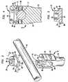
- FIG. 1is a perspective view of an elongated spinal rod of a spinal stabilization system having attached thereto a bone screw and a bone hook constructed in accordance with a first embodiment of the subject disclosure;
- FIG. 2is a perspective view of a locking cap which forms part of the bone screw and bone hook illustrated in FIG. 1 , oriented in an inverted position for ease of illustration;
- FIG. 3is a perspective view of the bone screw and locking cap of FIG. 1 separated from one another for ease of illustration;
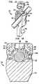
- FIG. 4is a cross-sectional view of the bone screw of the subject disclosure taken along line 4 - 4 of FIG. 1 ;
- FIG. 5is a cross-sectional view of the locking cap taken along line 5 - 5 of FIG. 3 ;
- FIGS. 6A through 6Dillustrate operative steps associated with attaching the bone fastener of the subject disclosure to a spinal rod wherein:
- FIG. 6Aillustrates the step of positioning the spinal rod and locking cap in the reception channel of the head portion of a fastening device of the subject disclosure
- FIG. 6Billustrates the initial orientation of the locking cap relative to the head portion of a fastening device of the subject disclosure wherein the locking cap is in an unlocked position
- FIG. 6Cillustrates the rotation of the locking cap relative to the head portion of a fastening device of the subject disclosure to a partially locked position
- FIG. 6Dillustrates the rotation of the locking cap relative to the head portion of a fastening device of the subject disclosure to a locked position
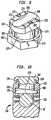
- FIG. 7is a perspective view of a fastening device constructed in accordance with a second embodiment of the subject disclosure.
- FIG. 8is a perspective view of the fastening device of FIG. 7 with the locking cap separated for ease of illustration;
- FIG. 9is a perspective view of the locking cap of the fastener device of FIG. 7 , oriented in an inverted position for ease of illustration;
- FIG. 10is a cross-sectional view of the fastening device of FIG. 7 taken along line 10 - 10 of FIG. 7 ;
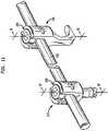
- FIG. 11is a perspective view of an elongated spinal rod of a spinal stabilization system having attached thereto another version of a bone screw and another version of a bone hook constructed in accordance with another embodiment of the subject disclosure;
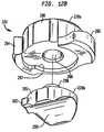
- FIG. 12Ais an exploded perspective view of the bone screw of FIG. 11 with parts separated for ease of illustration including the two-piece locking cap and multi-axial fastener portion associated therewith;
- FIG. 12Bis a perspective view, looking upward from below, of the two-piece locking cap of the subject disclosure illustrating the bottom surface features of the component parts thereof:
- FIG. 13is a cross-sectional view of the bone screw of FIG. 11 taken along line 13 - 13 of FIG. 11 with the two-piece locking cap in a locked position;
- FIGS. 14A through 14Cillustrate, in counter-clockwise progression, the operative steps associated with attaching the bone screw of FIG. 11 to a spinal rod by employing the two-piece locking cap of the subject disclosure, wherein:
- FIG. 14Aillustrates the step of positioning the locking cap within the head portion of the bone screw
- FIG. 14Billustrates the initial unlocked orientation of the upper portion of the locking cap within the head portion of the bone screw
- FIG. 14Cillustrates the step of rotating the upper portion of the locking cap relative to the lower portion of the locking cap and the head portion of the bone screw into a locked position to secure the position of the bone screw with respect to the spinal rod;
- FIG. 15is an exploded perspective view of the bone hook of FIG. 11 with parts separated for ease of illustration including the two-piece locking cap associated therewith;
- FIG. 16is a cross-sectional view of the bone hook of FIG. 11 taken along line 16 - 16 of FIG. 11 with the two-piece locking cap in a locked positions.
- FIG. 1a section of a spinal stabilization system constructed in accordance with a preferred embodiment of the subject disclosure and designated generally by reference numeral 10 .
- spinal stabilization system 10includes an elongated spinal rod 12 having a circular cross-section and a substantially smooth outer surface finish.
- fastening devicesin the form of a bone screw 14 and right-angle hook 16 are provided for securing spinal rod 12 to the spine during a spinal stabilization procedure.
- Both fastening devicesemploy a novel top-loaded locking cap, designated generally by reference numeral 20 , which will be described in greater detail hereinbelow with reference to FIG. 2 .
- the novel locking capachieves significant clinical advantages over the prior art through its reliability and the ease in which it is installed during a spinal stabilization procedure.
- the subject disclosureis not limited in any way to the illustrated bone screw and right-angle hook. Rather, these particular fasteners are merely examples of the type of devices that can employ the novel locking cap disclosed herein.
- Other fasteners commonly utilized in spinal stabilization systemssuch as, for example, hooks having alternative angular geometries as well as clamps are also envisioned. Indeed, it is envisioned that any component designed for attachment to an elongated spinal rod or transverse coupling rod, may incorporate the novel locking cap of the subject disclosure. Also, any number of fastening devices can be applied along the length of the spinal rod.
- bone screw 14includes a head portion 22 defining a horizontal axis and a vertical axis.
- a shank portion 24depends from the head portion and a threaded portion 26 having a helical thread extending about the outer periphery depends from the shank portion.
- the helical threadis particularly adapted to securely engage the vertebral bodies of the spine.
- a channel 28extends through the head portion 22 along the horizontal axis thereof for receiving elongated spinal rod 12 .
- channel 28is defined by the interior surfaces of side walls 30 and 32 and the curved lower surface 29 , which extends therebetween.
- Locking cap 20is dimensioned and configured for reception and engagement in locking channel 28 to secure the position of bone screw 14 with respect to spinal rod 12 during a spinal stabilization procedure.
- right-angle hook 16includes a head portion 42 defining a horizontal axis and a vertical axis.
- a hook portion 46depends from the head portion 42 for securement to a vertebral body of the spine.
- a channel 48extends through the head portion 42 along the horizontal axis thereof for receiving elongated spinal rod 12 .
- Channel 48is defined by the interior surfaces of opposed side walls 50 and 52 and a curved lower surface extending therebetween.
- Locking cap 20is dimensioned and configured for reception and engagement in channel 48 to secure the position of hook 16 with respect to spinal rod 12 during a spinal stabilization procedure.
- Locking cap 20in an inverted position to best illustrate structural aspects thereof
- Locking cap 20includes a cylindrical head 62 and a flanged portion 64 .
- the bottom surface 66 of flanged portion 64includes an elongate recess 68 having a curvature complementary to spinal rod 12 for accommodating the spinal rod when locking cap 20 is in an unlocked position, shown for example in FIG. 6B .
- the fastening devicemay be moved freely along or rotated about the longitudinal axis of the spinal rod.
- Bottom surface 66also includes a bifurcated orthogonal recess 70 which intersects the elongate recess at a 90° angle and has a curvature complementary to spinal rod 12 to accommodate the spinal rod when locking cap 20 is in a locked position, shown for example in FIG. 6D and FIG. 4 .
- bottom surface 66includes bifurcated first and second transverse recesses 72 and 74 which intersect the elongate recess 68 at opposite angles of intersection and have curvatures which are complementary to spinal rod 12 to accommodate the spinal rod when the locking cap 20 is in either of two intermediate positions, one of which is shown for example in FIG. 6C .
- the fastening deviceretains the spinal rod but is not fully secured, and if desired by the surgeon, locking cap 20 can be rotated from the intermediate position and the fastener moved to an alternative location on the spinal rod.
- the transverse recessesintersect the elongate recess at opposed 45° angles.
- the transverse recesscan be oriented at alternative intersecting angles. It is also contemplated that the bottom surface can be flat without any recesses.
- the cylindrical head 62 of locking cap 20includes a hexagonal axial bore 80 extending partially therethrough for receiving a working implement such as a wrench to facilitate rotation of the locking cap 20 relative to the head portion 22 of the fastening device about the vertical axis defined thereby. It envisioned that alternative tooling configurations known in the art can also be utilized to facilitate axial rotation of locking cap 20 during a surgical procedure. Curved notches 76 and 78 are formed in the inner surfaces of opposed walls 30 and 32 for accommodating the cylindrical head 62 of locking cap 20 when the locking cap is received and rotated within channel 28 .
- the flanged portion 64 of locking cap 20is defined in part by two diametrically opposed arcuate engagement flanges 82 and 84 which are dimensioned and configured for operative engagement with two complementary diametrically opposed arcuate engagement slots 86 and 88 defined in the interior surfaces of the opposed side walls 30 and 32 of head portion 22 . (See FIG. 4 ).
- engagement flanges 82 and 84define ramped camming surfaces 92 and 94 , respectively.
- Camming surfaces 92 and 94are of opposite angular inclination with respect to one another. More particularly, each engagement flange has a low side (e.g., 82 a of flange 82 ) and a high side (e.g., 82 b of flange 82 ), whereby the low sides of the two flanges are diametrically opposed from one another as are the high sides.
- the camming surfaces of the flangesare mirror images of one another.
- the locking capcan be initially oriented with either flange aligned to engage either slot. This versatility adds to the ease in which the locking cap is installed during a surgical procedure.
- the arcuate engagement slots 86 and 88 in head portion 22 of fastener 14have inclined surfaces that mate with the ramped camming surfaces 92 and 94 of flanges 82 and 84 .
- the ramped camming surfaces 92 and 94are tapered radially inwardly to enhance the interlock with the mating surfaces of arcuate engagement slots 86 and 88 , which are also tapered to complement the radially inward taper of camming surfaces 92 and 94 .
- This interlocking relationshipserves to prevent the opposed side walls 30 and 32 of head portion 22 from spreading radially outward as the arcuate flanges are engaged with the arcuate slots when the locking cap 20 is rotated to a locked position.
- FIGS. 6A through 6Dillustrate the steps in securing the fastening device to the spinal rod during a surgical procedure.
- attachment of a bone screw 14is shown, it should be understood, as noted above, that other fastening devices, e.g., bone hooks, can be secured to the spinal rod 12 using the locking cap and head portion structure of the present disclosure.
- spinal rod 12is moved into approximation with the horizontal channel 28 of head portion 22 such that the periphery of the spinal rod 12 is in registration with the curved surface 29 of the channel 28 .
- Locking cap 20is then top loaded into the channel along the vertical axis of the fastener in the direction of arrow a.
- spinal rod 12is accommodated within the elongate recess 68 defined in the bottom surface 66 of locking cap 20 and the bone screw 14 may be moved freely relative to the spinal rod.
- the opposed flanged sections 82 and 84 of locking cap 20are 900 out of phase from the opposed arcuate engagement slots 86 and 88 defined in head portion 22 , as shown for example in FIG. 6B .
- locking cap 20is rotated 45° relative to head portion 22 about the vertical axis thereof.
- spinal rod 12is accommodated within one of the two transverse recesses 72 or 74 , depending upon the initial orientation of the locking cap 20 with respect to the head portion.
- the opposed arcuate engagement flanges 82 and 84 of locking cap 20are only partially engaged with the opposed arcuate engagement slots 86 and 88 defined in head portion 22 , as they are 45° out of phase with the slots. Consequently, the locking cap holds the fastener 22 and spinal rod 12 together, but does not lock the fastener. In this position, the locking cap 20 can be readily rotated in the opposite direction to disengage from the spinal rod 12 to adjust the position of the bone screw 14 with respect to the spinal rod 12 .
- locking cap 20is rotated another 90° to the locked position illustrated in FIG. 6D .
- spinal, rod 12is accommodated within the orthogonal recess 70 defined in the bottom surface of locking cap 20 .
- the opposed engagement flanges 82 and 84 of flanged portion 64are fully engaged with the opposed engagement slots 86 and 88 of head portion 22 and the longitudinal and angular orientations of the bone screw 14 are fixed with respect to spinal rod 12 , as illustrated in FIG. 4 .
- the manner and method by which bone screw 14 hook is attached to spinal rod 12is identical to the manner and method by which hook 16 or other fasteners are attached to spinal rod 12 .
- locking cap 20Since the rotational range of locking cap 20 is limited, i.e., the locking cap can only be rotated 90°, it will be readily appreciated that the cap cannot be over-torqued. Thus, the damage often caused by over-tightening a conventional threaded locking mechanism, such as a set screw, is avoided. Furthermore, since the locking cap of the subject disclosure has a predetermined locked position, it is unlikely that it will be under-torqued or left in a loose condition after installation as is common with threaded set screws found in the prior art. That is, by having a predetermined locked position, uniform locking forces are provided for all of the fastening devices used to secure the spinal rod 12 along its length and cross threading is reduced.
- Fastening device 110is similar to fastening devices 12 and 14 in that it is particularly designed to facilitate securement of a spinal rod to the spine in a convenient manner.
- Fastening device 110includes a head portion 122 having opposed side walls 130 and 132 , which define a horizontal channel 128 in conjunction with the curved lower surface 129 extending therebetween.
- Arcuate tabs 176 and 178project upwardly from side walls 130 and 132 , respectively, for interacting with locking cap, 120 .
- locking cap 120which is shown in an inverted position for ease of illustration, includes a hexagonal head 162 a cylindrical body 163 and a flanged portion 164 .
- the hexagonal head 162is adapted and configured for interaction with a wrench or similar work implement.
- An annular channel 165extends into the bottom surface of hexagonal head 162 for receiving arcuate tabs 176 and 168 This positive interaction serves to prevent the opposed side walls 130 and 132 of head portion 122 from spreading radially outwardly when arcuate flanges 182 and 184 of locking cap 120 are engaged in arcuate slots 186 and 188 of head portion 122 upon rotation of locking cap 20 into a locked position.
- the ramped camming surfaces 192 and 194 of the arcuate engagement flanges 182 and 184need not be provided with radially inwardly directed tapers as provided on flanges 82 and 84 of the locking cap 20 of the embodiment of FIGS. 1-6 .
- the bottom surface 166 of the flanged portion 164 of locking cap 120is configured in substantially the same manner as the bottom surface 66 of locking cap 20 in that it is provided with an elongate recess 168 for accommodating a spinal rod when the locking cap 120 is in an unlocked position, first and second bifurcated transverse recesses 172 and 174 which intersect the elongate recess 168 at opposite 45° angles to accommodate the spinal rod when the locking cap 120 is in either of two intermediate positions, and a bifurcated orthogonal recess 170 which intersects the elongate recess at a 90° angle to accommodate the spinal rod when the locking cap 120 is in a final locked position, as shown in FIG. 10 .
- locking cap 120is engaged with fastening device 110 in a manner that is substantially similar to the manner in which locking cap 20 is engaged with bone fastener 14 and hook 16 , and that the configuration of the bottom surface of flanged portion 164 provides the same benefits afforded by the flanged portion 64 of locking cap 20 .
- FIG. 11there is illustrated two additional fastening devices constructed in accordance with the subject disclosure in the form of a multi-axial bone screw 214 and a right-angle hook 216 which are provided for securing spinal rod 212 to the spine during a spinal stabilization procedure.
- Both fastening devicesemploy a novel top loaded two-piece locking cap, designated generally by reference numeral 220 , which will be described in greater detail hereinbelow with reference to FIGS. 12 and 13 .
- the novel two-piece locking capachieves significant clinical advantages over the prior art through its reliability and the ease in which it is installed during a spinal stabilization procedure. As with respect to the previously described embodiments of FIG.
- the novel two-piece locking capmay be used in conjunction with other types of fasteners commonly employed in spinal stabilization procedures.
- the two-piece locking cap illustrated in FIG. 11is employed with a multi-axial bone screw, it is readily apparent that the same two-piece locking cap could be employed with a fixed axis bone screw such as that which is illustrated in FIG. 1 .
- the multi-axial bone screw 214includes a head portion 222 defining a horizontal axis “x” and a vertical axis “y”.
- a channel 228extends through the head portion 222 along the horizontal axis “x” for receiving an elongated spinal rod 212 .
- Channel 228is defined by the interior surfaces of the side walls 230 and 232 of head portion 222 .
- Bone screw 214further includes a fastener portion 224 , which includes a generally spherical head 225 and a threaded body 226 . Threaded body 226 depends from and is monolithically formed with the spherical head 225 .
- the threaded bodyincludes a helical thread formation that is particularly adapted to securely engage the vertebral bodies of the spine.
- the head portion 222 of multi-axial bone screw 214further defines a generally cylindrical vertical channel 227 , which extends through and is aligned with the vertical axis “y” of the head portion 222 .
- Vertical channel 227is configured to receive and accommodate the fastener portion 224 of bone screw 214 .
- a lower interior surface portion of vertical channel 227defines an annular seating surface 229 configured to cooperate with the lower hemi-spherical region of spherical head 225 .
- the cooperative engagement between the two structurespermits the relative movement of the fastener portion 224 with respect to the head potion 222 about the vertical axis y.
- the multi-axial motion afforded theretoenhances the operational range of bone screw 214 , providing greater flexibility to the surgeon during a spinal stabilization procedure.
- Bone screw 214further includes an annular retention ring 232 that is accommodated within a corresponding annular groove 234 formed within the cylindrical wall of vertical channel 227 (see FIG. 13 ).
- Retention ring 232is adapted to positively engage the spherical head 225 and aiding in its stabilization.
- the lower hemi-spherical region of head 225is scored with a series of circular ridges adapted to enhance the frictional coefficient of the seating surface defined thereby.
- bone screw 214further includes a two-piece locking cap 220 which is dimensioned and configured for reception and engagement in the horizontal channel 228 of head portion 220 to secure the position of head portion 222 with respect to spinal rod 212 during a spinal stabilization procedure.
- the securement of locking cap 220 within channel 228also achieves positive fixation of the angular position of the fastener portion 224 with respect to the head portion 222 and the vertical axis “y” defined thereby.
- locking cap 220includes an upper portion 220 a and a lower portion 220 b .
- the upper portion 220 aincludes a cylindrical cap body 280 defining an axial reception port 282 for receiving a tool or working implement that applies torque to the cap during installation.
- Upper portion 220 afurther includes a pair of circumferentially opposed arcuate engagement flanges, 284 and 286 which extend radially outwardly from cap body 280 .
- Engagement flanges 284 and 286include inclined radially inwardly slopping camming surfaces for cooperating with complementary opposed arcuate engagement slots 294 and 296 formed in the opposed side walls 230 and 232 of head portion 222 (see FIG. 13 ).
- the flanges 284 , 286become engaged in corresponding slots 294 , 296 upon rotation of the upper portion 220 a of locking cap 220 relative to the head portion 222 of bone screw 214 .
- the lower portion 220 b of locking cap 220is configured for cooperative reception within the cylindrical vertical channel 227 of head portion 222 and is adapted to engage the spinal rod 212 extending through the horizontal channel 228 of head portion 222 .
- the body 285 of the lower portion 220 bhas curved exterior surfaces, which complement the curvature of the walls defining vertical channel 227 .
- Body portion 285includes an extension flange 302 which aides in the alignment and positioning of the lower cap portion 220 a with respect to spinal rod 212 .
- the bottom surface of the upper portion 220 a of locking cap 220includes a recessed seating area 287 and an associated axial reception bore 288 .
- the recessed seating area 287is dimensioned and configured to accommodate the body of the lower portion 220 b of locking cap 220
- the reception bore 288is dimensioned and configured to receive and engage an axial post 298 which projects from the upper surface 295 of the lower portion 220 b of locking cap 220 . More particularly, during assembly, when the axial post 298 is received by the reception bore 288 , the top end of the post is swaged (flared out) to join the two components together (see FIG. 13 ).
- the interaction of the axial post 298 and axial reception bore 288facilitates relative rotational movement of the upper portion 220 a relative to the lower portion 220 b when the locking cap 220 is loaded into and locked in the head portion 222 of bone screw 214 during a spinal stabilization procedure.
- the two-part locking capenables a surgeon to load the locking cap 220 into vertical channel 227 and properly position the lower portion 220 b against the spinal rod 212 so as to ensure an intimate engagement between the hemi-cylindrical channel 299 and the cylindrical surface of the spinal rod. Thereafter, the upper portion 220 a may be rotated into a locked portion relative to the lower portion 220 b.
- the fastener portion 226 of bone screw 214is first seated within the head portion 222 . Then, the head portion 222 is positioned at the surgical site in such a manner so that the elongated spinal rod 212 extends through the horizontal channel 228 as illustrated in FIG. 14A . Thereafter, if necessary, the fastener portion 226 may be moved into a desired angular orientation by the surgeon and subsequently mounted to the spinous process using suitable surgical instruments.
- the locking cap 220is loaded into the vertical channel 227 of head portion 222 along the vertical axis “y” defined thereby.
- the hemi-cylindrical channel 299 on the undersurface of lower portion 220 bwill become intimately engaged with the cylindrical surface of the spinal rod 212 and it will be maintained in a fixed axial orientation with respect to the spinal rod due to the mating relationship between the body of the lower portion 220 b and the vertical channel 227 .
- Locking cap 220must be loaded in such a manner so that the radially outwardly extending engagement flanges 284 and 286 of upper portion 220 a are parallel to the axis of the spinal rod 212 , as illustrated in FIG. 14B . Otherwise, the flanges will interfere with the opposed side walls 230 and 232 of the head portion 222 . Furthermore, care must be taken to ensure that the upper portion 220 a of locking cap 220 is positioned in such a manner so that the low sides of the flanges (e.g. 284 a ) are aligned with the high sides of the engagement channels (e.g. 294 a ), or the flanges will not cammingly engage the channels upon rotation of the upper portion 220 a of the locking cap 220 relative to the head portion 222 of bone screw 214 .
- the upper portion 220 a of locking cap 220has been properly oriented with respect to head portion 222 with the extension flange 302 in alignment with spinal rod 212 , it is rotated in a clockwise direction about the vertical axis “y” relative to the lower portion 220 b of locking cap 220 and the head portion 222 of bone screw 214 using an appropriate surgical implement or tool (not shown). Thereupon, the arcuate engagement flanges 284 , 286 of upper portion 220 cammingly engage the corresponding engagement slots 284 .
- the lower portion 220 b of the locking cap 220will be seated within the recessed seating area 287 defined in the bottom surface 285 of the upper portion 220 a of locking cap 220 (See FIG. 13 ).
- the position of the head portion 222 of bone screw 214is fixed with respect to longitudinal axis of spinal rod 212 and the position of the fastener portion 226 of bone screw 214 is fixed with respect to the vertical axis “y” defined by head portion 222 of bone screw 214 , as illustrated in FIG. 14C .
- the right-angle hook 216 of the subject disclosureincludes a head portion 242 defining a horizontal axis x and a vertical axis “y”.
- a hook portion 246depends from the head portion 242 to facilitate securement of the device to a vertebral body of the spine.
- a channel 248extends through the head portion 242 along the horizontal axis thereof for receiving elongated spinal rod 212 .
- Channel 248is defined by the interior surfaces of opposed upstanding side walls 250 and 252 and a contoured lower surface extending therebetween for complementing the shape of the rod.
- Channel 248is further configured to receive a two-piece locking cap 220 adapted to secure the position of hook 216 with respect to spinal rod 212 during a spinal stabilization procedure.
- the locking cap 220includes an upper portion 220 a and a lower portion 220 b , which are rotatably joined together.
- the upper portionincludes a pair of circumferentially opposed arcuate engagement flanges 284 and 286 for cooperating with complementary opposed arcuate engagement slots 255 and 257 formed in the opposed side walls 250 and 252 of head portion 242 .
- the flanges 284 , 286become engaged in corresponding slots 255 , 257 upon rotation of the upper portion 220 a of locking cap 220 relative to the lower portion 220 b of the locking cap and the head portion 242 of right-angle hook 216 .
Landscapes
- Health & Medical Sciences (AREA)
- Orthopedic Medicine & Surgery (AREA)
- Life Sciences & Earth Sciences (AREA)
- Neurology (AREA)
- Surgery (AREA)
- Heart & Thoracic Surgery (AREA)
- Engineering & Computer Science (AREA)
- Biomedical Technology (AREA)
- Nuclear Medicine, Radiotherapy & Molecular Imaging (AREA)
- Medical Informatics (AREA)
- Molecular Biology (AREA)
- Animal Behavior & Ethology (AREA)
- General Health & Medical Sciences (AREA)
- Public Health (AREA)
- Veterinary Medicine (AREA)
- Surgical Instruments (AREA)
- Prostheses (AREA)
Abstract
Description
Claims (43)
Priority Applications (1)
| Application Number | Priority Date | Filing Date | Title |
|---|---|---|---|
| US11/415,902US7909856B2 (en) | 1998-06-17 | 2006-05-02 | Methods for securing spinal rods |
Applications Claiming Priority (5)
| Application Number | Priority Date | Filing Date | Title |
|---|---|---|---|
| US09/098,927US6090111A (en) | 1998-06-17 | 1998-06-17 | Device for securing spinal rods |
| US16743998A | 1998-10-06 | 1998-10-06 | |
| US09/487,942US6565565B1 (en) | 1998-06-17 | 2000-01-19 | Device for securing spinal rods |
| US10/365,182US7608095B2 (en) | 1998-06-17 | 2003-02-12 | Device for securing spinal rods |
| US11/415,902US7909856B2 (en) | 1998-06-17 | 2006-05-02 | Methods for securing spinal rods |
Related Parent Applications (1)
| Application Number | Title | Priority Date | Filing Date |
|---|---|---|---|
| US10/365,182ContinuationUS7608095B2 (en) | 1998-06-17 | 2003-02-12 | Device for securing spinal rods |
Publications (2)
| Publication Number | Publication Date |
|---|---|
| US20060247636A1 US20060247636A1 (en) | 2006-11-02 |
| US7909856B2true US7909856B2 (en) | 2011-03-22 |
Family
ID=23937747
Family Applications (8)
| Application Number | Title | Priority Date | Filing Date |
|---|---|---|---|
| US09/487,942Expired - LifetimeUS6565565B1 (en) | 1998-06-17 | 2000-01-19 | Device for securing spinal rods |
| US10/091,708Expired - Fee RelatedUS7780703B2 (en) | 1998-06-17 | 2002-03-06 | Device for securing spinal rods |
| US10/365,182Expired - Fee RelatedUS7608095B2 (en) | 1998-06-17 | 2003-02-12 | Device for securing spinal rods |
| US11/216,849Expired - Fee RelatedUS7819901B2 (en) | 1998-06-17 | 2005-08-31 | Device for securing spinal rods |
| US11/415,902Expired - Fee RelatedUS7909856B2 (en) | 1998-06-17 | 2006-05-02 | Methods for securing spinal rods |
| US12/546,863Expired - Fee RelatedUS8038702B2 (en) | 1998-06-17 | 2009-08-25 | Device for securing spinal rods |
| US12/827,230Expired - Fee RelatedUS8313510B2 (en) | 1998-06-17 | 2010-06-30 | Device for securing spinal rods |
| US13/653,751Expired - Fee RelatedUS8808327B2 (en) | 1998-06-17 | 2012-10-17 | Device for securing spinal rods |
Family Applications Before (4)
| Application Number | Title | Priority Date | Filing Date |
|---|---|---|---|
| US09/487,942Expired - LifetimeUS6565565B1 (en) | 1998-06-17 | 2000-01-19 | Device for securing spinal rods |
| US10/091,708Expired - Fee RelatedUS7780703B2 (en) | 1998-06-17 | 2002-03-06 | Device for securing spinal rods |
| US10/365,182Expired - Fee RelatedUS7608095B2 (en) | 1998-06-17 | 2003-02-12 | Device for securing spinal rods |
| US11/216,849Expired - Fee RelatedUS7819901B2 (en) | 1998-06-17 | 2005-08-31 | Device for securing spinal rods |
Family Applications After (3)
| Application Number | Title | Priority Date | Filing Date |
|---|---|---|---|
| US12/546,863Expired - Fee RelatedUS8038702B2 (en) | 1998-06-17 | 2009-08-25 | Device for securing spinal rods |
| US12/827,230Expired - Fee RelatedUS8313510B2 (en) | 1998-06-17 | 2010-06-30 | Device for securing spinal rods |
| US13/653,751Expired - Fee RelatedUS8808327B2 (en) | 1998-06-17 | 2012-10-17 | Device for securing spinal rods |
Country Status (7)
| Country | Link |
|---|---|
| US (8) | US6565565B1 (en) |
| EP (2) | EP1723919B1 (en) |
| JP (1) | JP4546687B2 (en) |
| AU (1) | AU776517B2 (en) |
| CA (1) | CA2397112C (en) |
| DE (1) | DE60030477T2 (en) |
| WO (1) | WO2001052758A1 (en) |
Cited By (26)
| Publication number | Priority date | Publication date | Assignee | Title |
|---|---|---|---|---|
| US20100249856A1 (en)* | 2009-03-27 | 2010-09-30 | Andrew Iott | Devices and Methods for Inserting a Vertebral Fixation Member |
| US8007518B2 (en) | 2008-02-26 | 2011-08-30 | Spartek Medical, Inc. | Load-sharing component having a deflectable post and method for dynamic stabilization of the spine |
| US8012181B2 (en) | 2008-02-26 | 2011-09-06 | Spartek Medical, Inc. | Modular in-line deflection rod and bone anchor system and method for dynamic stabilization of the spine |
| US8016861B2 (en) | 2008-02-26 | 2011-09-13 | Spartek Medical, Inc. | Versatile polyaxial connector assembly and method for dynamic stabilization of the spine |
| US8021396B2 (en) | 2007-06-05 | 2011-09-20 | Spartek Medical, Inc. | Configurable dynamic spinal rod and method for dynamic stabilization of the spine |
| US8048115B2 (en) | 2007-06-05 | 2011-11-01 | Spartek Medical, Inc. | Surgical tool and method for implantation of a dynamic bone anchor |
| US8057517B2 (en) | 2008-02-26 | 2011-11-15 | Spartek Medical, Inc. | Load-sharing component having a deflectable post and centering spring and method for dynamic stabilization of the spine |
| US8083775B2 (en) | 2008-02-26 | 2011-12-27 | Spartek Medical, Inc. | Load-sharing bone anchor having a natural center of rotation and method for dynamic stabilization of the spine |
| US8083772B2 (en) | 2007-06-05 | 2011-12-27 | Spartek Medical, Inc. | Dynamic spinal rod assembly and method for dynamic stabilization of the spine |
| US8092501B2 (en) | 2007-06-05 | 2012-01-10 | Spartek Medical, Inc. | Dynamic spinal rod and method for dynamic stabilization of the spine |
| US8097024B2 (en) | 2008-02-26 | 2012-01-17 | Spartek Medical, Inc. | Load-sharing bone anchor having a deflectable post and method for stabilization of the spine |
| US8114134B2 (en) | 2007-06-05 | 2012-02-14 | Spartek Medical, Inc. | Spinal prosthesis having a three bar linkage for motion preservation and dynamic stabilization of the spine |
| US20120071926A1 (en)* | 2010-09-16 | 2012-03-22 | Jani Mehul R | Transverse Connector |
| US8211155B2 (en) | 2008-02-26 | 2012-07-03 | Spartek Medical, Inc. | Load-sharing bone anchor having a durable compliant member and method for dynamic stabilization of the spine |
| US8257397B2 (en) | 2009-12-02 | 2012-09-04 | Spartek Medical, Inc. | Low profile spinal prosthesis incorporating a bone anchor having a deflectable post and a compound spinal rod |
| US8267979B2 (en) | 2008-02-26 | 2012-09-18 | Spartek Medical, Inc. | Load-sharing bone anchor having a deflectable post and axial spring and method for dynamic stabilization of the spine |
| US8317836B2 (en) | 2007-06-05 | 2012-11-27 | Spartek Medical, Inc. | Bone anchor for receiving a rod for stabilization and motion preservation spinal implantation system and method |
| US8333792B2 (en) | 2008-02-26 | 2012-12-18 | Spartek Medical, Inc. | Load-sharing bone anchor having a deflectable post and method for dynamic stabilization of the spine |
| US8337536B2 (en) | 2008-02-26 | 2012-12-25 | Spartek Medical, Inc. | Load-sharing bone anchor having a deflectable post with a compliant ring and method for stabilization of the spine |
| US8430916B1 (en) | 2012-02-07 | 2013-04-30 | Spartek Medical, Inc. | Spinal rod connectors, methods of use, and spinal prosthesis incorporating spinal rod connectors |
| US8518085B2 (en) | 2010-06-10 | 2013-08-27 | Spartek Medical, Inc. | Adaptive spinal rod and methods for stabilization of the spine |
| US9271759B2 (en) | 2012-03-09 | 2016-03-01 | Institute Of Musculoskeletal Science And Education, Ltd. | Pedicle screw assembly with locking cap |
| US9707100B2 (en) | 2015-06-25 | 2017-07-18 | Institute for Musculoskeletal Science and Education, Ltd. | Interbody fusion device and system for implantation |
| US9750545B2 (en) | 2009-03-27 | 2017-09-05 | Globus Medical, Inc. | Devices and methods for inserting a vertebral fixation member |
| US11872143B2 (en) | 2016-10-25 | 2024-01-16 | Camber Spine Technologies, LLC | Spinal fusion implant |
| US11877935B2 (en) | 2016-10-18 | 2024-01-23 | Camber Spine Technologies, LLC | Implant with deployable blades |
Families Citing this family (432)
| Publication number | Priority date | Publication date | Assignee | Title |
|---|---|---|---|---|
| FR2760963B1 (en)* | 1997-03-18 | 1999-11-05 | Albert P Alby | IMPLANT FOR OSTEOSYNTHESIS DEVICE AND TOOL FOR MOUNTING SUCH AN IMPLANT |
| US6565565B1 (en)* | 1998-06-17 | 2003-05-20 | Howmedica Osteonics Corp. | Device for securing spinal rods |
| US7691145B2 (en) | 1999-10-22 | 2010-04-06 | Facet Solutions, Inc. | Prostheses, systems and methods for replacement of natural facet joints with artificial facet joint surfaces |
| ATE285207T1 (en) | 1999-10-22 | 2005-01-15 | Archus Orthopedics Inc | FACET ARTHROPLASTY DEVICES |
| US6811567B2 (en)* | 1999-10-22 | 2004-11-02 | Archus Orthopedics Inc. | Facet arthroplasty devices and methods |
| US7674293B2 (en) | 2004-04-22 | 2010-03-09 | Facet Solutions, Inc. | Crossbar spinal prosthesis having a modular design and related implantation methods |
| US8187303B2 (en) | 2004-04-22 | 2012-05-29 | Gmedelaware 2 Llc | Anti-rotation fixation element for spinal prostheses |
| FR2812185B1 (en) | 2000-07-25 | 2003-02-28 | Spine Next Sa | SEMI-RIGID CONNECTION PIECE FOR RACHIS STABILIZATION |
| FR2812186B1 (en) | 2000-07-25 | 2003-02-28 | Spine Next Sa | FLEXIBLE CONNECTION PIECE FOR SPINAL STABILIZATION |
| US7833250B2 (en)* | 2004-11-10 | 2010-11-16 | Jackson Roger P | Polyaxial bone screw with helically wound capture connection |
| US7837716B2 (en)* | 2000-08-23 | 2010-11-23 | Jackson Roger P | Threadform for medical implant closure |
| US6755829B1 (en)* | 2000-09-22 | 2004-06-29 | Depuy Acromed, Inc. | Lock cap anchor assembly for orthopaedic fixation |
| US6726689B2 (en) | 2002-09-06 | 2004-04-27 | Roger P. Jackson | Helical interlocking mating guide and advancement structure |
| US8377100B2 (en) | 2000-12-08 | 2013-02-19 | Roger P. Jackson | Closure for open-headed medical implant |
| JP2002204802A (en)* | 2001-01-10 | 2002-07-23 | Showa Ika Kohgyo Co Ltd | Osteosynthesis joining member |
| US6451021B1 (en)* | 2001-02-15 | 2002-09-17 | Third Millennium Engineering, Llc | Polyaxial pedicle screw having a rotating locking element |
| FR2822053B1 (en) | 2001-03-15 | 2003-06-20 | Stryker Spine Sa | ANCHORING MEMBER WITH SAFETY RING FOR SPINAL OSTEOSYNTHESIS SYSTEM |
| FR2823095B1 (en)* | 2001-04-06 | 2004-02-06 | Ldr Medical | RACHIS OSTEOSYNTHESIS DEVICE AND PLACEMENT METHOD |
| US10729469B2 (en) | 2006-01-09 | 2020-08-04 | Roger P. Jackson | Flexible spinal stabilization assembly with spacer having off-axis core member |
| US7862587B2 (en) | 2004-02-27 | 2011-01-04 | Jackson Roger P | Dynamic stabilization assemblies, tool set and method |
| US10258382B2 (en) | 2007-01-18 | 2019-04-16 | Roger P. Jackson | Rod-cord dynamic connection assemblies with slidable bone anchor attachment members along the cord |
| US8353932B2 (en) | 2005-09-30 | 2013-01-15 | Jackson Roger P | Polyaxial bone anchor assembly with one-piece closure, pressure insert and plastic elongate member |
| US20160242816A9 (en) | 2001-05-09 | 2016-08-25 | Roger P. Jackson | Dynamic spinal stabilization assembly with elastic bumpers and locking limited travel closure mechanisms |
| US8292926B2 (en) | 2005-09-30 | 2012-10-23 | Jackson Roger P | Dynamic stabilization connecting member with elastic core and outer sleeve |
| FR2829014B1 (en)* | 2001-09-03 | 2005-04-08 | Stryker Spine | SPINAL OSTEOSYNTHESIS SYSTEM COMPRISING A SUPPORT SKATE |
| US6793657B2 (en)* | 2001-09-10 | 2004-09-21 | Solco Biomedical Co., Ltd. | Spine fixing apparatus |
| FR2831048B1 (en) | 2001-10-18 | 2004-09-17 | Ldr Medical | PROGRESSIVE APPROACH OSTEOSYNTHESIS DEVICE AND PRE-ASSEMBLY PROCESS |
| FR2831049B1 (en)* | 2001-10-18 | 2004-08-13 | Ldr Medical | PLATE FOR OSTEOSYNTHESIS DEVICE AND PRE-ASSEMBLY METHOD |
| FR2833151B1 (en) | 2001-12-12 | 2004-09-17 | Ldr Medical | BONE ANCHORING IMPLANT WITH POLYAXIAL HEAD |
| US6755833B1 (en) | 2001-12-14 | 2004-06-29 | Kamaljit S. Paul | Bone support assembly |
| US7070599B2 (en) | 2002-07-24 | 2006-07-04 | Paul Kamaljit S | Bone support assembly |
| CN1432343A (en)* | 2002-01-17 | 2003-07-30 | 英属维京群岛商冠亚生技控股集团股份有限公司 | Rotary controlled vertebra fixture |
| CN1221217C (en)* | 2002-01-24 | 2005-10-05 | 英属维京群岛商冠亚生技控股集团股份有限公司 | Rotary button fixator for vertebration fixing |
| US7658582B2 (en)* | 2003-07-09 | 2010-02-09 | Ortho Innovations, Llc | Precise linear fastener system and method for use |
| US7879075B2 (en) | 2002-02-13 | 2011-02-01 | Zimmer Spine, Inc. | Methods for connecting a longitudinal member to a bone portion |
| US7066937B2 (en)* | 2002-02-13 | 2006-06-27 | Endius Incorporated | Apparatus for connecting a longitudinal member to a bone portion |
| WO2003086204A2 (en)* | 2002-04-09 | 2003-10-23 | Neville Alleyne | Bone fixation apparatus |
| US7842073B2 (en)* | 2002-04-18 | 2010-11-30 | Aesculap Ii, Inc. | Screw and rod fixation assembly and device |
| US6740086B2 (en) | 2002-04-18 | 2004-05-25 | Spinal Innovations, Llc | Screw and rod fixation assembly and device |
| US11224464B2 (en) | 2002-05-09 | 2022-01-18 | Roger P. Jackson | Threaded closure with inwardly-facing tool engaging concave radiused structures and axial through-aperture |
| US7278995B2 (en) | 2002-06-04 | 2007-10-09 | Howmedica Osteonics Corp. | Apparatus for securing a spinal rod system |
| AU2003244854A1 (en)* | 2002-07-09 | 2004-01-23 | Anglo-European College Of Chiropractic Ltd | Method for imaging the relative motion of skeletal segments |
| EP1562499B1 (en)* | 2002-09-04 | 2006-04-26 | Aesculap AG & Co. KG | Orthopedic fixation device |
| US8282673B2 (en) | 2002-09-06 | 2012-10-09 | Jackson Roger P | Anti-splay medical implant closure with multi-surface removal aperture |
| WO2006052796A2 (en) | 2004-11-10 | 2006-05-18 | Jackson Roger P | Helical guide and advancement flange with break-off extensions |
| US8257402B2 (en) | 2002-09-06 | 2012-09-04 | Jackson Roger P | Closure for rod receiving orthopedic implant having left handed thread removal |
| US8876868B2 (en) | 2002-09-06 | 2014-11-04 | Roger P. Jackson | Helical guide and advancement flange with radially loaded lip |
| US8162989B2 (en)* | 2002-11-04 | 2012-04-24 | Altus Partners, Llc | Orthopedic rod system |
| US8328850B2 (en)* | 2002-12-23 | 2012-12-11 | Choice Spine, Lp | Device for immobilizing a connecting rod in an osseous anchoring element of a rachidian implant |
| US8172885B2 (en) | 2003-02-05 | 2012-05-08 | Pioneer Surgical Technology, Inc. | Bone plate system |
| GB2436005B (en)* | 2003-02-05 | 2007-11-21 | Pioneer Lab Inc | Low profile spinal fixation system |
| US7141051B2 (en)* | 2003-02-05 | 2006-11-28 | Pioneer Laboratories, Inc. | Low profile spinal fixation system |
| US20040186473A1 (en)* | 2003-03-21 | 2004-09-23 | Cournoyer John R. | Spinal fixation devices of improved strength and rigidity |
| US20060200128A1 (en)* | 2003-04-04 | 2006-09-07 | Richard Mueller | Bone anchor |
| US7621918B2 (en) | 2004-11-23 | 2009-11-24 | Jackson Roger P | Spinal fixation tool set and method |
| US8540753B2 (en)* | 2003-04-09 | 2013-09-24 | Roger P. Jackson | Polyaxial bone screw with uploaded threaded shank and method of assembly and use |
| US6716214B1 (en)* | 2003-06-18 | 2004-04-06 | Roger P. Jackson | Polyaxial bone screw with spline capture connection |
| FR2853522A1 (en)* | 2003-04-10 | 2004-10-15 | Jean Pierre Huitema | TIGHTENING DEVICE CONCERNING PEDICULAR SCREWS AND LAMINARY HOOKS IN THE CONTEXT OF RACHIS OPERATIONS |
| US7608104B2 (en) | 2003-05-14 | 2009-10-27 | Archus Orthopedics, Inc. | Prostheses, tools and methods for replacement of natural facet joints with artifical facet joint surfaces |
| US20040230304A1 (en) | 2003-05-14 | 2004-11-18 | Archus Orthopedics Inc. | Prostheses, tools and methods for replacement of natural facet joints with artifical facet joint surfaces |
| US7377923B2 (en) | 2003-05-22 | 2008-05-27 | Alphatec Spine, Inc. | Variable angle spinal screw assembly |
| JP5078355B2 (en) | 2003-05-23 | 2012-11-21 | グローバス メディカル インコーポレイティッド | Spine stabilization system |
| US6986771B2 (en)* | 2003-05-23 | 2006-01-17 | Globus Medical, Inc. | Spine stabilization system |
| US7967850B2 (en) | 2003-06-18 | 2011-06-28 | Jackson Roger P | Polyaxial bone anchor with helical capture connection, insert and dual locking assembly |
| US8926670B2 (en) | 2003-06-18 | 2015-01-06 | Roger P. Jackson | Polyaxial bone screw assembly |
| US8366753B2 (en)* | 2003-06-18 | 2013-02-05 | Jackson Roger P | Polyaxial bone screw assembly with fixed retaining structure |
| US8137386B2 (en) | 2003-08-28 | 2012-03-20 | Jackson Roger P | Polyaxial bone screw apparatus |
| US8257398B2 (en)* | 2003-06-18 | 2012-09-04 | Jackson Roger P | Polyaxial bone screw with cam capture |
| US8377102B2 (en) | 2003-06-18 | 2013-02-19 | Roger P. Jackson | Polyaxial bone anchor with spline capture connection and lower pressure insert |
| US8398682B2 (en) | 2003-06-18 | 2013-03-19 | Roger P. Jackson | Polyaxial bone screw assembly |
| US8092500B2 (en) | 2007-05-01 | 2012-01-10 | Jackson Roger P | Dynamic stabilization connecting member with floating core, compression spacer and over-mold |
| JP4357486B2 (en)* | 2003-06-18 | 2009-11-04 | ロジャー・ピー・ジャクソン | Polyaxial bone screw with spline capture connection |
| US7766915B2 (en) | 2004-02-27 | 2010-08-03 | Jackson Roger P | Dynamic fixation assemblies with inner core and outer coil-like member |
| US7776067B2 (en)* | 2005-05-27 | 2010-08-17 | Jackson Roger P | Polyaxial bone screw with shank articulation pressure insert and method |
| US20040260283A1 (en)* | 2003-06-19 | 2004-12-23 | Shing-Cheng Wu | Multi-axis spinal fixation device |
| US20040260284A1 (en)* | 2003-06-23 | 2004-12-23 | Matthew Parker | Anti-splay pedicle screw |
| US7087057B2 (en) | 2003-06-27 | 2006-08-08 | Depuy Acromed, Inc. | Polyaxial bone screw |
| US6945975B2 (en)* | 2003-07-07 | 2005-09-20 | Aesculap, Inc. | Bone fixation assembly and method of securement |
| US6945974B2 (en) | 2003-07-07 | 2005-09-20 | Aesculap Inc. | Spinal stabilization implant and method of application |
| US7074238B2 (en) | 2003-07-08 | 2006-07-11 | Archus Orthopedics, Inc. | Prostheses, tools and methods for replacement of natural facet joints with artificial facet joint surfaces |
| FR2859095B1 (en) | 2003-09-01 | 2006-05-12 | Ldr Medical | BONE ANCHORING IMPLANT WITH A POLYAXIAL HEAD AND METHOD OF PLACING THE IMPLANT |
| FR2859376B1 (en)* | 2003-09-04 | 2006-05-19 | Spine Next Sa | SPINAL IMPLANT |
| US7632294B2 (en)* | 2003-09-29 | 2009-12-15 | Promethean Surgical Devices, Llc | Devices and methods for spine repair |
| US20050080414A1 (en)* | 2003-10-14 | 2005-04-14 | Keyer Thomas R. | Spinal fixation hooks and method of spinal fixation |
| US20050080415A1 (en)* | 2003-10-14 | 2005-04-14 | Keyer Thomas R. | Polyaxial bone anchor and method of spinal fixation |
| US7588575B2 (en)* | 2003-10-21 | 2009-09-15 | Innovative Spinal Technologies | Extension for use with stabilization systems for internal structures |
| US7967826B2 (en) | 2003-10-21 | 2011-06-28 | Theken Spine, Llc | Connector transfer tool for internal structure stabilization systems |
| US7744633B2 (en) | 2003-10-22 | 2010-06-29 | Pioneer Surgical Technology, Inc. | Crosslink for securing spinal rods |
| EP1527742B1 (en)* | 2003-10-31 | 2006-07-26 | Spinelab AG | Locking cap for pedicle screws for fixing of elastic rods |
| US7090674B2 (en)* | 2003-11-03 | 2006-08-15 | Spinal, Llc | Bone fixation system with low profile fastener |
| US7083622B2 (en)* | 2003-11-10 | 2006-08-01 | Simonson Peter M | Artificial facet joint and method |
| US20050101953A1 (en)* | 2003-11-10 | 2005-05-12 | Simonson Peter M. | Artificial facet joint and method |
| US7708764B2 (en) | 2003-11-10 | 2010-05-04 | Simonson Peter M | Method for creating an artificial facet |
| TW200518711A (en)* | 2003-12-11 | 2005-06-16 | A Spine Holding Group Corp | Rotation buckling ball-head spine restoring equipment |
| US20050131406A1 (en) | 2003-12-15 | 2005-06-16 | Archus Orthopedics, Inc. | Polyaxial adjustment of facet joint prostheses |
| US7527638B2 (en) | 2003-12-16 | 2009-05-05 | Depuy Spine, Inc. | Methods and devices for minimally invasive spinal fixation element placement |
| US11419642B2 (en) | 2003-12-16 | 2022-08-23 | Medos International Sarl | Percutaneous access devices and bone anchor assemblies |
| US7179261B2 (en) | 2003-12-16 | 2007-02-20 | Depuy Spine, Inc. | Percutaneous access devices and bone anchor assemblies |
| US7601153B2 (en) | 2003-12-25 | 2009-10-13 | Homs Engineering Inc. | Intramedullary nail |
| US7635366B2 (en)* | 2003-12-29 | 2009-12-22 | Abdou M Samy | Plating system for bone fixation and method of implantation |
| US7678137B2 (en)* | 2004-01-13 | 2010-03-16 | Life Spine, Inc. | Pedicle screw constructs for spine fixation systems |
| US8900277B2 (en) | 2004-02-26 | 2014-12-02 | Pioneer Surgical Technology, Inc. | Bone plate system |
| US7740649B2 (en) | 2004-02-26 | 2010-06-22 | Pioneer Surgical Technology, Inc. | Bone plate system and methods |
| US7311712B2 (en)* | 2004-02-26 | 2007-12-25 | Aesculap Implant Systems, Inc. | Polyaxial locking screw plate assembly |
| US8152810B2 (en) | 2004-11-23 | 2012-04-10 | Jackson Roger P | Spinal fixation tool set and method |
| US7892257B2 (en) | 2004-02-27 | 2011-02-22 | Custom Spine, Inc. | Spring loaded, load sharing polyaxial pedicle screw assembly and method |
| US7862594B2 (en)* | 2004-02-27 | 2011-01-04 | Custom Spine, Inc. | Polyaxial pedicle screw assembly |
| US7819902B2 (en)* | 2004-02-27 | 2010-10-26 | Custom Spine, Inc. | Medialised rod pedicle screw assembly |
| US7160300B2 (en) | 2004-02-27 | 2007-01-09 | Jackson Roger P | Orthopedic implant rod reduction tool set and method |
| US11241261B2 (en) | 2005-09-30 | 2022-02-08 | Roger P Jackson | Apparatus and method for soft spinal stabilization using a tensionable cord and releasable end structure |
| US7163539B2 (en)* | 2004-02-27 | 2007-01-16 | Custom Spine, Inc. | Biased angle polyaxial pedicle screw assembly |
| US7789896B2 (en) | 2005-02-22 | 2010-09-07 | Jackson Roger P | Polyaxial bone screw assembly |
| JP2007525274A (en) | 2004-02-27 | 2007-09-06 | ロジャー・ピー・ジャクソン | Orthopedic implant rod reduction instrument set and method |
| US8475495B2 (en)* | 2004-04-08 | 2013-07-02 | Globus Medical | Polyaxial screw |
| US7503924B2 (en)* | 2004-04-08 | 2009-03-17 | Globus Medical, Inc. | Polyaxial screw |
| US7678139B2 (en)* | 2004-04-20 | 2010-03-16 | Allez Spine, Llc | Pedicle screw assembly |
| WO2006055186A2 (en) | 2004-10-25 | 2006-05-26 | Archus Orthopedics, Inc. | Spinal prosthesis having a modular design |
| US7051451B2 (en) | 2004-04-22 | 2006-05-30 | Archus Orthopedics, Inc. | Facet joint prosthesis measurement and implant tools |
| US7914556B2 (en) | 2005-03-02 | 2011-03-29 | Gmedelaware 2 Llc | Arthroplasty revision system and method |
| US7406775B2 (en)* | 2004-04-22 | 2008-08-05 | Archus Orthopedics, Inc. | Implantable orthopedic device component selection instrument and methods |
| FR2869523A1 (en)* | 2004-04-28 | 2005-11-04 | Frederic Fortin | FLEXIBLE AND MODULAR VERTEBRAL CONNECTION DEVICE HAVING AN ADJUSTABLE ELEMENT FOR WORKING MULTIDIRECTIONALLY |
| US7766941B2 (en)* | 2004-05-14 | 2010-08-03 | Paul Kamaljit S | Spinal support, stabilization |
| ATE343974T1 (en)* | 2004-06-08 | 2006-11-15 | A Spine Holding Group Corp | ROTATABLE DEVICE FOR RESTORING A SPINE UNDER TREATMENT |
| US7763049B2 (en)* | 2004-06-09 | 2010-07-27 | Zimmer Spine, Inc. | Orthopedic fixation connector |
| US7935135B2 (en)* | 2004-06-09 | 2011-05-03 | Zimmer Spine, Inc. | Spinal fixation device |
| US7264621B2 (en)* | 2004-06-17 | 2007-09-04 | Sdgi Holdings, Inc. | Multi-axial bone attachment assembly |
| US8034082B2 (en) | 2004-07-08 | 2011-10-11 | Globus Medical, Inc. | Transverse fixation device for spinal fixation systems |
| DE202004020396U1 (en) | 2004-08-12 | 2005-07-07 | Columbus Trading-Partners Pos und Brendel GbR (vertretungsberechtigte Gesellschafter Karin Brendel, 95503 Hummeltal und Bohumila Pos, 95445 Bayreuth) | Child seat for motor vehicles |
| AU2005277363A1 (en) | 2004-08-18 | 2006-03-02 | Fsi Acquisition Sub, Llc | Adjacent level facet arthroplasty devices, spine stabilization systems, and methods |
| US8951290B2 (en)* | 2004-08-27 | 2015-02-10 | Blackstone Medical, Inc. | Multi-axial connection system |
| US20060058788A1 (en)* | 2004-08-27 | 2006-03-16 | Hammer Michael A | Multi-axial connection system |
| US7959653B2 (en)* | 2004-09-03 | 2011-06-14 | Lanx, Inc. | Spinal rod cross connector |
| US7651502B2 (en) | 2004-09-24 | 2010-01-26 | Jackson Roger P | Spinal fixation tool set and method for rod reduction and fastener insertion |
| US8366747B2 (en)* | 2004-10-20 | 2013-02-05 | Zimmer Spine, Inc. | Apparatus for connecting a longitudinal member to a bone portion |
| US8267969B2 (en)* | 2004-10-20 | 2012-09-18 | Exactech, Inc. | Screw systems and methods for use in stabilization of bone structures |
| US8226690B2 (en) | 2005-07-22 | 2012-07-24 | The Board Of Trustees Of The Leland Stanford Junior University | Systems and methods for stabilization of bone structures |
| US7604655B2 (en) | 2004-10-25 | 2009-10-20 | X-Spine Systems, Inc. | Bone fixation system and method for using the same |
| WO2006047711A2 (en) | 2004-10-25 | 2006-05-04 | Alphaspine, Inc. | Pedicle screw systems and methods |
| WO2006047555A2 (en)* | 2004-10-25 | 2006-05-04 | Alphaspine, Inc. | Bone fixation systems and methods |
| US7513905B2 (en)* | 2004-11-03 | 2009-04-07 | Jackson Roger P | Polyaxial bone screw |
| US8926672B2 (en) | 2004-11-10 | 2015-01-06 | Roger P. Jackson | Splay control closure for open bone anchor |
| US7572279B2 (en)* | 2004-11-10 | 2009-08-11 | Jackson Roger P | Polyaxial bone screw with discontinuous helically wound capture connection |
| DE102004056091B8 (en) | 2004-11-12 | 2007-04-26 | Aesculap Ag & Co. Kg | Orthopedic fixation device and orthopedic fixation system |
| US9168069B2 (en) | 2009-06-15 | 2015-10-27 | Roger P. Jackson | Polyaxial bone anchor with pop-on shank and winged insert with lower skirt for engaging a friction fit retainer |
| ATE536821T1 (en) | 2004-11-23 | 2011-12-15 | Roger P Jackson | POLYAXIAL BONE SCREW WITH MULTIPLE SHAFT FIXATION |
| US9216041B2 (en) | 2009-06-15 | 2015-12-22 | Roger P. Jackson | Spinal connecting members with tensioned cords and rigid sleeves for engaging compression inserts |
| US8444681B2 (en) | 2009-06-15 | 2013-05-21 | Roger P. Jackson | Polyaxial bone anchor with pop-on shank, friction fit retainer and winged insert |
| US7875065B2 (en) | 2004-11-23 | 2011-01-25 | Jackson Roger P | Polyaxial bone screw with multi-part shank retainer and pressure insert |
| US8308782B2 (en) | 2004-11-23 | 2012-11-13 | Jackson Roger P | Bone anchors with longitudinal connecting member engaging inserts and closures for fixation and optional angulation |
| WO2006057837A1 (en) | 2004-11-23 | 2006-06-01 | Jackson Roger P | Spinal fixation tool attachment structure |
| US9980753B2 (en) | 2009-06-15 | 2018-05-29 | Roger P Jackson | pivotal anchor with snap-in-place insert having rotation blocking extensions |
| WO2006058221A2 (en) | 2004-11-24 | 2006-06-01 | Abdou Samy M | Devices and methods for inter-vertebral orthopedic device placement |
| US7935137B2 (en)* | 2004-12-08 | 2011-05-03 | Depuy Spine, Inc. | Locking bone screw and spinal plate system |
| US7736380B2 (en) | 2004-12-21 | 2010-06-15 | Rhausler, Inc. | Cervical plate system |
| US20070299450A1 (en)* | 2004-12-31 | 2007-12-27 | Ji-Hoon Her | Pedicle Screw and Device for Injecting Bone Cement into Bone |
| US7302945B2 (en)* | 2005-01-21 | 2007-12-04 | Gregg L. Ewing | Compound archery bow with an adaptor device for carrying a compound archery bow |
| US7625376B2 (en)* | 2005-01-26 | 2009-12-01 | Warsaw Orthopedic, Inc. | Reducing instrument for spinal surgery |
| US7445627B2 (en)* | 2005-01-31 | 2008-11-04 | Alpinespine, Llc | Polyaxial pedicle screw assembly |
| AU2006214001B2 (en) | 2005-02-18 | 2011-05-26 | Samy Abdou | Devices and methods for dynamic fixation of skeletal structure |
| US7604654B2 (en) | 2005-02-22 | 2009-10-20 | Stryker Spine | Apparatus and method for dynamic vertebral stabilization |
| US12102357B2 (en) | 2005-02-22 | 2024-10-01 | Roger P. Jackson | Pivotal bone anchor assembly with cannulated shank having a planar top surface and method of assembly |
| US8403962B2 (en) | 2005-02-22 | 2013-03-26 | Roger P. Jackson | Polyaxial bone screw assembly |
| US7476239B2 (en)* | 2005-05-10 | 2009-01-13 | Jackson Roger P | Polyaxial bone screw with compound articulation |
| US7901437B2 (en) | 2007-01-26 | 2011-03-08 | Jackson Roger P | Dynamic stabilization member with molded connection |
| US10076361B2 (en) | 2005-02-22 | 2018-09-18 | Roger P. Jackson | Polyaxial bone screw with spherical capture, compression and alignment and retention structures |
| WO2008024937A2 (en) | 2006-08-23 | 2008-02-28 | Pioneer Surgical Technology, Inc. | Minimally invasive surgical system |
| EP1858422A4 (en)* | 2005-02-23 | 2011-12-28 | Pioneer Surgical Technology Inc | Minimally invasive surgical system |
| WO2006096756A2 (en)* | 2005-03-07 | 2006-09-14 | Abdou M Samy | Occipital fixation system |
| US7338491B2 (en)* | 2005-03-22 | 2008-03-04 | Spinefrontier Inc | Spinal fixation locking mechanism |
| US8496686B2 (en) | 2005-03-22 | 2013-07-30 | Gmedelaware 2 Llc | Minimally invasive spine restoration systems, devices, methods and kits |
| US7794481B2 (en)* | 2005-04-22 | 2010-09-14 | Warsaw Orthopedic, Inc. | Force limiting coupling assemblies for spinal implants |
| TWI375545B (en) | 2005-04-25 | 2012-11-01 | Synthes Gmbh | Bone anchor with locking cap and method of spinal fixation |
| CA2614898C (en)* | 2005-04-27 | 2014-04-22 | Trinity Orthopedics, Llc | Mono-planar pedilcle screw method, system, and kit |
| US7811310B2 (en)* | 2005-05-04 | 2010-10-12 | Spinefrontier, Inc | Multistage spinal fixation locking mechanism |
| US20060264252A1 (en)* | 2005-05-23 | 2006-11-23 | White Gehrig H | System and method for providing a host console for use with an electronic card game |
| JP4613867B2 (en)* | 2005-05-26 | 2011-01-19 | ソニー株式会社 | Content processing apparatus, content processing method, and computer program |
| JP5580530B2 (en)* | 2005-06-07 | 2014-08-27 | グローバス メディカル インコーポレイティッド | Multi screw |
| US20070043364A1 (en)* | 2005-06-17 | 2007-02-22 | Cawley Trace R | Spinal correction system with multi-stage locking mechanism |
| WO2007011431A2 (en)* | 2005-07-18 | 2007-01-25 | Dong Myung Jeon | Bi-polar bone screw assembly |
| US20090036929A1 (en)* | 2005-07-22 | 2009-02-05 | Joey Camia Reglos | Offset connector for a spinal stabilization rod |
| US8523865B2 (en) | 2005-07-22 | 2013-09-03 | Exactech, Inc. | Tissue splitter |
| US7766946B2 (en)* | 2005-07-27 | 2010-08-03 | Frank Emile Bailly | Device for securing spinal rods |
| US7717943B2 (en) | 2005-07-29 | 2010-05-18 | X-Spine Systems, Inc. | Capless multiaxial screw and spinal fixation assembly and method |
| US7625394B2 (en)* | 2005-08-05 | 2009-12-01 | Warsaw Orthopedic, Inc. | Coupling assemblies for spinal implants |
| WO2007022790A1 (en)* | 2005-08-23 | 2007-03-01 | Synthes Gmbh | An osteosynthetic clamp for attaching a bone anchor to a support rod |
| US7628799B2 (en) | 2005-08-23 | 2009-12-08 | Aesculap Ag & Co. Kg | Rod to rod connector |
| US7761849B2 (en)* | 2005-08-25 | 2010-07-20 | Microsoft Corporation | Automated analysis and recovery of localization data |
| CH705709B1 (en)* | 2005-08-29 | 2013-05-15 | Bird Biedermann Ag | Spinal implant. |
| DE502006002049D1 (en)* | 2005-09-13 | 2008-12-24 | Bird Biedermann Ag | Dynamic clamping device for spinal implant |
| US7955358B2 (en) | 2005-09-19 | 2011-06-07 | Albert Todd J | Bone screw apparatus, system and method |
| EP1926443B1 (en)* | 2005-09-23 | 2013-04-03 | Synthes GmbH | Bone support apparatus |
| US12357348B2 (en) | 2005-09-30 | 2025-07-15 | Roger P. Jackson | Method of assembling a pivotal bone anchor assembly with press-in-place insert |
| US8105368B2 (en) | 2005-09-30 | 2012-01-31 | Jackson Roger P | Dynamic stabilization connecting member with slitted core and outer sleeve |
| WO2007041702A2 (en) | 2005-10-04 | 2007-04-12 | Alphaspine, Inc. | Pedicle screw system with provisional locking aspects |
| US7857833B2 (en)* | 2005-10-06 | 2010-12-28 | Abdou M Samy | Devices and methods for inter-vertebral orthopedic device placement |
| US7572268B2 (en)* | 2005-10-13 | 2009-08-11 | Bacoustics, Llc | Apparatus and methods for the selective removal of tissue using combinations of ultrasonic energy and cryogenic energy |
| US8097025B2 (en) | 2005-10-25 | 2012-01-17 | X-Spine Systems, Inc. | Pedicle screw system configured to receive a straight or curved rod |
| US8137385B2 (en) | 2005-10-31 | 2012-03-20 | Stryker Spine | System and method for dynamic vertebral stabilization |
| US8100946B2 (en)* | 2005-11-21 | 2012-01-24 | Synthes Usa, Llc | Polyaxial bone anchors with increased angulation |
| WO2007075454A1 (en)* | 2005-12-19 | 2007-07-05 | Synthes (U.S.A) | Polyaxial bone anchor with headless pedicle screw |
| US7704271B2 (en) | 2005-12-19 | 2010-04-27 | Abdou M Samy | Devices and methods for inter-vertebral orthopedic device placement |
| ES2323008T3 (en)* | 2005-12-23 | 2009-07-03 | Biedermann Motech Gmbh | DEVICE OF DYNAMIC STABILIZATION OF BONES OR VERTEBRAS. |
| US7819899B2 (en)* | 2006-01-03 | 2010-10-26 | Zimmer Spine, Inc. | Instrument for pedicle screw adhesive materials |
| US7833252B2 (en) | 2006-01-27 | 2010-11-16 | Warsaw Orthopedic, Inc. | Pivoting joints for spinal implants including designed resistance to motion and methods of use |
| US7722652B2 (en) | 2006-01-27 | 2010-05-25 | Warsaw Orthopedic, Inc. | Pivoting joints for spinal implants including designed resistance to motion and methods of use |
| US8057519B2 (en) | 2006-01-27 | 2011-11-15 | Warsaw Orthopedic, Inc. | Multi-axial screw assembly |
| US8740947B2 (en)* | 2006-02-15 | 2014-06-03 | Warsaw, Orthopedic, Inc. | Multiple lead bone fixation apparatus |
| US20070233064A1 (en)* | 2006-02-17 | 2007-10-04 | Holt Development L.L.C. | Apparatus and method for flexible spinal fixation |
| US20080269804A1 (en)* | 2006-02-17 | 2008-10-30 | Holt Development L.L.C. | Apparatus and method for flexible spinal fixation |
| US7641674B2 (en)* | 2006-03-01 | 2010-01-05 | Warsaw Orthopedic, Inc. | Devices for securing elongated spinal connecting elements in bone anchors |
| CA2647026A1 (en)* | 2006-03-22 | 2008-08-28 | Pioneer Surgical Technology, Inc. | Low top bone fixation system and method for using the same |
| WO2007114834A1 (en)* | 2006-04-05 | 2007-10-11 | Dong Myung Jeon | Multi-axial, double locking bone screw assembly |
| WO2007121271A2 (en) | 2006-04-11 | 2007-10-25 | Synthes (U.S.A) | Minimally invasive fixation system |
| US20070270813A1 (en)* | 2006-04-12 | 2007-11-22 | Laszlo Garamszegi | Pedicle screw assembly |
| US8676293B2 (en)* | 2006-04-13 | 2014-03-18 | Aecc Enterprises Ltd. | Devices, systems and methods for measuring and evaluating the motion and function of joint structures and associated muscles, determining suitability for orthopedic intervention, and evaluating efficacy of orthopedic intervention |
| US7922749B2 (en)* | 2006-04-14 | 2011-04-12 | Warsaw Orthopedic, Inc. | Reducing device |
| US8216240B2 (en)* | 2006-04-24 | 2012-07-10 | Warsaw Orthopedic | Cam based reduction instrument |
| US20070255284A1 (en)* | 2006-04-28 | 2007-11-01 | Sdgi Holdings, Inc. | Orthopedic implant apparatus |
| US20070270831A1 (en)* | 2006-05-01 | 2007-11-22 | Sdgi Holdings, Inc. | Bone anchor system utilizing a molded coupling member for coupling a bone anchor to a stabilization member and method therefor |
| US20070270832A1 (en)* | 2006-05-01 | 2007-11-22 | Sdgi Holdings, Inc. | Locking device and method, for use in a bone stabilization system, employing a set screw member and deformable saddle member |
| US7914559B2 (en)* | 2006-05-30 | 2011-03-29 | Warsaw Orthopedic, Inc. | Locking device and method employing a posted member to control positioning of a stabilization member of a bone stabilization system |
| US20080058808A1 (en) | 2006-06-14 | 2008-03-06 | Spartek Medical, Inc. | Implant system and method to treat degenerative disorders of the spine |
| WO2008008511A2 (en) | 2006-07-14 | 2008-01-17 | Laszlo Garamszegi | Pedicle screw assembly with inclined surface seat |
| US8388660B1 (en) | 2006-08-01 | 2013-03-05 | Samy Abdou | Devices and methods for superior fixation of orthopedic devices onto the vertebral column |
| US8702755B2 (en) | 2006-08-11 | 2014-04-22 | Gmedelaware 2 Llc | Angled washer polyaxial connection for dynamic spine prosthesis |
| US8062340B2 (en)* | 2006-08-16 | 2011-11-22 | Pioneer Surgical Technology, Inc. | Spinal rod anchor device and method |
| EP1891904B1 (en)* | 2006-08-24 | 2013-12-25 | Biedermann Technologies GmbH & Co. KG | Bone anchoring device |
| ES2336815T5 (en)* | 2006-09-15 | 2013-05-16 | Biedermann Technologies Gmbh & Co. Kg | Bone anchoring device |
| US7981144B2 (en)* | 2006-09-21 | 2011-07-19 | Integrity Intellect, Inc. | Implant equipped for nerve location and method of use |
| US7988711B2 (en) | 2006-09-21 | 2011-08-02 | Warsaw Orthopedic, Inc. | Low profile vertebral stabilization systems and methods |
| WO2008039790A1 (en)* | 2006-09-25 | 2008-04-03 | Zimmer Spine, Inc. | Apparatus for connecting a longitudinal member to a bone portion |
| US7918857B2 (en) | 2006-09-26 | 2011-04-05 | Depuy Spine, Inc. | Minimally invasive bone anchor extensions |
| US20080096493A1 (en)* | 2006-10-20 | 2008-04-24 | Jason Kerwood | Communication device for rock climbing and the like |
| US8096996B2 (en) | 2007-03-20 | 2012-01-17 | Exactech, Inc. | Rod reducer |
| US8162990B2 (en)* | 2006-11-16 | 2012-04-24 | Spine Wave, Inc. | Multi-axial spinal fixation system |
| CA2670988C (en) | 2006-12-08 | 2014-03-25 | Roger P. Jackson | Tool system for dynamic spinal implants |
| WO2008082836A1 (en)* | 2006-12-29 | 2008-07-10 | Abbott Spine Inc. | Spinal stabilization systems and methods |
| US8636783B2 (en)* | 2006-12-29 | 2014-01-28 | Zimmer Spine, Inc. | Spinal stabilization systems and methods |
| US8747445B2 (en) | 2007-01-15 | 2014-06-10 | Ebi, Llc | Spinal fixation device |
| US8475498B2 (en) | 2007-01-18 | 2013-07-02 | Roger P. Jackson | Dynamic stabilization connecting member with cord connection |
| US8366745B2 (en) | 2007-05-01 | 2013-02-05 | Jackson Roger P | Dynamic stabilization assembly having pre-compressed spacers with differential displacements |
| US11224463B2 (en) | 2007-01-18 | 2022-01-18 | Roger P. Jackson | Dynamic stabilization connecting member with pre-tensioned flexible core member |
| US10792074B2 (en) | 2007-01-22 | 2020-10-06 | Roger P. Jackson | Pivotal bone anchor assemly with twist-in-place friction fit insert |
| KR100991204B1 (en)* | 2007-01-23 | 2010-11-01 | 주식회사 바이오스마트 | Spinos process for spine spacer |
| US7942906B2 (en)* | 2007-02-12 | 2011-05-17 | Neurospine Innovations And Solutions, Llc | Spinal stabilization system for the stabilization and fixation of the lumbar spine and method for using same |
| US8012177B2 (en) | 2007-02-12 | 2011-09-06 | Jackson Roger P | Dynamic stabilization assembly with frusto-conical connection |
| US8167912B2 (en) | 2007-02-27 | 2012-05-01 | The Center for Orthopedic Research and Education, Inc | Modular pedicle screw system |
| US8926669B2 (en)* | 2007-02-27 | 2015-01-06 | The Center For Orthopedic Research And Education, Inc. | Modular polyaxial pedicle screw system |
| US7959655B2 (en)* | 2007-03-06 | 2011-06-14 | Warsaw Orthopedic, Inc. | Self-aligning attachment devices and methods for attaching an elongated member to a vertebral member |
| US7967849B2 (en)* | 2007-04-06 | 2011-06-28 | Warsaw Orthopedic, Inc. | Adjustable multi-axial spinal coupling assemblies |
| US10383660B2 (en) | 2007-05-01 | 2019-08-20 | Roger P. Jackson | Soft stabilization assemblies with pretensioned cords |
| US8979904B2 (en) | 2007-05-01 | 2015-03-17 | Roger P Jackson | Connecting member with tensioned cord, low profile rigid sleeve and spacer with torsion control |
| US8016832B2 (en)* | 2007-05-02 | 2011-09-13 | Zimmer Spine, Inc. | Installation systems for spinal stabilization system and related methods |
| US8197517B1 (en) | 2007-05-08 | 2012-06-12 | Theken Spine, Llc | Frictional polyaxial screw assembly |
| US8197518B2 (en) | 2007-05-16 | 2012-06-12 | Ortho Innovations, Llc | Thread-thru polyaxial pedicle screw system |
| US7942909B2 (en) | 2009-08-13 | 2011-05-17 | Ortho Innovations, Llc | Thread-thru polyaxial pedicle screw system |
| US7942910B2 (en) | 2007-05-16 | 2011-05-17 | Ortho Innovations, Llc | Polyaxial bone screw |
| US7947065B2 (en) | 2008-11-14 | 2011-05-24 | Ortho Innovations, Llc | Locking polyaxial ball and socket fastener |
| US7951173B2 (en) | 2007-05-16 | 2011-05-31 | Ortho Innovations, Llc | Pedicle screw implant system |
| US7942911B2 (en) | 2007-05-16 | 2011-05-17 | Ortho Innovations, Llc | Polyaxial bone screw |
| CA2690038C (en) | 2007-05-31 | 2012-11-27 | Roger P. Jackson | Dynamic stabilization connecting member with pre-tensioned solid core |
| US8109970B2 (en) | 2007-06-05 | 2012-02-07 | Spartek Medical, Inc. | Deflection rod system with a deflection contouring shield for a spine implant and method |
| US8052722B2 (en) | 2007-06-05 | 2011-11-08 | Spartek Medical, Inc. | Dual deflection rod system for a dynamic stabilization and motion preservation spinal implantation system and method |
| FR2916956B1 (en) | 2007-06-08 | 2012-12-14 | Ldr Medical | INTERSOMATIC CAGE, INTERVERTEBRAL PROSTHESIS, ANCHORING DEVICE AND IMPLANTATION INSTRUMENTATION |
| US20080312655A1 (en)* | 2007-06-14 | 2008-12-18 | X-Spine Systems, Inc. | Polyaxial screw system and method having a hinged receiver |
| JP5085730B2 (en)* | 2007-06-28 | 2012-11-28 | スピナル エレメンツ,インク. | Spine stabilization device |
| US20090005815A1 (en)* | 2007-06-28 | 2009-01-01 | Scott Ely | Dynamic stabilization system |
| US8623019B2 (en) | 2007-07-03 | 2014-01-07 | Pioneer Surgical Technology, Inc. | Bone plate system |
| US8361126B2 (en) | 2007-07-03 | 2013-01-29 | Pioneer Surgical Technology, Inc. | Bone plate system |
| US9439681B2 (en) | 2007-07-20 | 2016-09-13 | DePuy Synthes Products, Inc. | Polyaxial bone fixation element |
| PL2170192T3 (en)* | 2007-07-20 | 2011-07-29 | Synthes Gmbh | Polyaxial bone fixation element |
| US20100160980A1 (en)* | 2007-07-26 | 2010-06-24 | Biotechni America Spine Group, Inc. | Spinal fixation assembly |
| JP2010536533A (en)* | 2007-08-24 | 2010-12-02 | スピナル エレメンツ,インク. | Loop rod spinal fixation device |
| DE102007042953B4 (en)* | 2007-08-30 | 2015-01-22 | Aesculap Ag | Orthopedic retention system |
| DE102007042959B4 (en)* | 2007-08-30 | 2011-03-31 | Aesculap Ag | Surgical retaining screw |
| DE102007042958B4 (en)* | 2007-08-30 | 2015-03-19 | Aesculap Ag | Surgical holding system |
| US20090069849A1 (en)* | 2007-09-10 | 2009-03-12 | Oh Younghoon | Dynamic screw system |
| US8414588B2 (en) | 2007-10-04 | 2013-04-09 | Depuy Spine, Inc. | Methods and devices for minimally invasive spinal connection element delivery |
| US20090099481A1 (en)* | 2007-10-10 | 2009-04-16 | Adam Deitz | Devices, Systems and Methods for Measuring and Evaluating the Motion and Function of Joints and Associated Muscles |
| US7922747B2 (en) | 2007-10-17 | 2011-04-12 | X-Spine Systems, Inc. | Cross connector apparatus for spinal fixation rods |
| US8911477B2 (en) | 2007-10-23 | 2014-12-16 | Roger P. Jackson | Dynamic stabilization member with end plate support and cable core extension |
| US8398683B2 (en)* | 2007-10-23 | 2013-03-19 | Pioneer Surgical Technology, Inc. | Rod coupling assembly and methods for bone fixation |
| US20090112266A1 (en)* | 2007-10-25 | 2009-04-30 | Industrial Technology Research Institute | Spinal dynamic stabilization device |
| US8029539B2 (en) | 2007-12-19 | 2011-10-04 | X-Spine Systems, Inc. | Offset multiaxial or polyaxial screw, system and assembly |
| US8998958B2 (en)* | 2007-12-20 | 2015-04-07 | Aesculap Implant Systems, Llc | Locking device introducer instrument |
| US8864798B2 (en)* | 2008-01-18 | 2014-10-21 | Globus Medical, Inc. | Transverse connector |
| EP2082697B1 (en)* | 2008-01-28 | 2011-02-09 | Spinelab AG | Pedicular screw with a locking device |
| US8114077B2 (en)* | 2008-02-01 | 2012-02-14 | Stryker Trauma Sa | Clamping pin |
| EP2085037B1 (en)* | 2008-02-01 | 2013-07-24 | Stryker Trauma SA | Telescopic strut for an external fixator |
| EP2085038B1 (en)* | 2008-02-01 | 2011-11-30 | Stryker Trauma SA | Ball joint for an external fixator |
| US9277940B2 (en) | 2008-02-05 | 2016-03-08 | Zimmer Spine, Inc. | System and method for insertion of flexible spinal stabilization element |
| WO2009124196A2 (en)* | 2008-04-03 | 2009-10-08 | Life Spine, Inc. | Top loading polyaxial spine screw assembly with one step lockup |
| EP2265202B1 (en)* | 2008-04-22 | 2012-08-29 | Synthes GmbH | Bone fixation element with reduction tabs |
| US8932332B2 (en)* | 2008-05-08 | 2015-01-13 | Aesculap Implant Systems, Llc | Minimally invasive spinal stabilization system |
| US8303628B2 (en)* | 2008-05-14 | 2012-11-06 | Dewey Jonathan M | Spinal stabilization system |
| BRPI0801980A2 (en)* | 2008-05-29 | 2009-05-12 | M D T Ltda | minimally invasive percutaneous pedicular screw |
| WO2009155523A1 (en)* | 2008-06-19 | 2009-12-23 | Life Spine, Inc. | Spinal rod connectors configured to retain spinal rods of varying diameters |
| US20100004693A1 (en)* | 2008-07-01 | 2010-01-07 | Peter Thomas Miller | Cam locking spine stabilization system and method |
| US8118837B2 (en)* | 2008-07-03 | 2012-02-21 | Zimmer Spine, Inc. | Tapered-lock spinal rod connectors and methods for use |
| EP2339976B1 (en) | 2008-07-09 | 2016-03-16 | Icon Orthopaedic Concepts, LLC | Ankle arthrodesis nail and outrigger assembly |
| US8414584B2 (en) | 2008-07-09 | 2013-04-09 | Icon Orthopaedic Concepts, Llc | Ankle arthrodesis nail and outrigger assembly |
| US8167914B1 (en) | 2008-07-16 | 2012-05-01 | Zimmer Spine, Inc. | Locking insert for spine stabilization and method of use |
| US8197512B1 (en) | 2008-07-16 | 2012-06-12 | Zimmer Spine, Inc. | System and method for spine stabilization using resilient inserts |
| US8157846B2 (en)* | 2008-07-24 | 2012-04-17 | Ingenium S.A. | Locking mechanism with two-piece washer |
| AU2010260521C1 (en) | 2008-08-01 | 2013-08-01 | Roger P. Jackson | Longitudinal connecting member with sleeved tensioned cords |
| USD601702S1 (en)* | 2008-08-14 | 2009-10-06 | Yechiel Gotfried | Surgical instrument |
| EP2484300B1 (en)* | 2008-09-05 | 2015-05-20 | Biedermann Technologies GmbH & Co. KG | Stabilization device for bones, in particular for the spinal column |
| EP2355725B1 (en) | 2008-09-05 | 2017-03-08 | Synthes GmbH | Bone fixation assembly |
| JP5815407B2 (en) | 2008-09-12 | 2015-11-17 | ジンテス ゲゼルシャフト ミット ベシュレンクテル ハフツング | Spinal stabilization and guided fixation system |
| KR20110081208A (en) | 2008-09-29 | 2011-07-13 | 신세스 게엠바하 | Multi-Axis Bottom-Loading Screw and Rod Assemblies |
| US8506601B2 (en) | 2008-10-14 | 2013-08-13 | Pioneer Surgical Technology, Inc. | Low profile dual locking fixation system and offset anchor member |
| US8382809B2 (en)* | 2008-10-17 | 2013-02-26 | Omni Surgical | Poly-axial pedicle screw implements and lock screw therefor |
| US8292934B2 (en)* | 2008-10-17 | 2012-10-23 | Warsaw Orthopedic, Inc. | Dynamic anchor assembly for connecting elements in spinal surgical procedures |
| US8080040B2 (en)* | 2008-10-29 | 2011-12-20 | Warsaw Orthopedic, Inc. | Anchor with two member securing mechanism for attaching an elongated member to a bone |
| US20100114168A1 (en)* | 2008-10-30 | 2010-05-06 | Warsaw Orthopedic, Inc. | Anchor with non-threaded securing mechanism to attach an elongated member to a bone |
| CA2742399A1 (en) | 2008-11-03 | 2010-06-03 | Dustin M. Harvey | Uni-planar bone fixation assembly |
| US8075603B2 (en) | 2008-11-14 | 2011-12-13 | Ortho Innovations, Llc | Locking polyaxial ball and socket fastener |
| US20100160978A1 (en)* | 2008-12-23 | 2010-06-24 | John Carbone | Bone screw assembly with non-uniform material |
| US8636778B2 (en) | 2009-02-11 | 2014-01-28 | Pioneer Surgical Technology, Inc. | Wide angulation coupling members for bone fixation system |
| US8998961B1 (en) | 2009-02-26 | 2015-04-07 | Lanx, Inc. | Spinal rod connector and methods |
| US8241341B2 (en) | 2009-03-20 | 2012-08-14 | Spinal Usa, Inc. | Pedicle screws and methods of using the same |
| US9295504B2 (en) | 2009-03-31 | 2016-03-29 | Biomet C.V. | Intramedullary nail with locking key |
| KR20120013312A (en) | 2009-04-15 | 2012-02-14 | 신세스 게엠바하 | Orthodontic Connectors for Spinal Structures |
| CN102497828B (en) | 2009-05-20 | 2015-09-09 | 斯恩蒂斯有限公司 | What patient installed retracts part |
| US9668771B2 (en) | 2009-06-15 | 2017-06-06 | Roger P Jackson | Soft stabilization assemblies with off-set connector |
| CN103826560A (en) | 2009-06-15 | 2014-05-28 | 罗杰.P.杰克逊 | Polyaxial Bone Anchor with Socket Stem and Winged Inserts with Friction Fit Compression Collars |
| US11229457B2 (en) | 2009-06-15 | 2022-01-25 | Roger P. Jackson | Pivotal bone anchor assembly with insert tool deployment |
| US8998959B2 (en) | 2009-06-15 | 2015-04-07 | Roger P Jackson | Polyaxial bone anchors with pop-on shank, fully constrained friction fit retainer and lock and release insert |
| US8236035B1 (en) | 2009-06-16 | 2012-08-07 | Bedor Bernard M | Spinal fixation system and method |
| CA2764841A1 (en) | 2009-06-17 | 2010-12-23 | Synthes Usa, Llc | Revision connector for spinal constructs |
| USD746461S1 (en) | 2009-06-19 | 2015-12-29 | Life Spine, Inc. | Spinal rod connector |
| FR2946859B1 (en)* | 2009-06-22 | 2012-11-09 | Medicrea International | MATERIAL OF VERTEBRAL OSTEOSYNTHESIS. |
| KR20120051692A (en)* | 2009-07-16 | 2012-05-22 | 스파인세이브 아게 | Spinal implant set including a quick closure |
| US8152720B2 (en)* | 2009-08-05 | 2012-04-10 | Thomas Stuart Loftus | Retracto component system and method of using same |
| US20110066187A1 (en)* | 2009-09-11 | 2011-03-17 | Zimmer Spine, Inc. | Spinal stabilization system |
| US8568456B2 (en) | 2009-09-21 | 2013-10-29 | Globus Medical, Inc. | Transverse connector having a locking element for capturing multiple rods |
| WO2011038236A2 (en) | 2009-09-25 | 2011-03-31 | Ortho Kinematics, Inc. | Systems and devices for an integrated imaging system with real-time feedback loops and methods therefor |
| EP2485654B1 (en) | 2009-10-05 | 2021-05-05 | Jackson P. Roger | Polyaxial bone anchor with non-pivotable retainer and pop-on shank, some with friction fit |
| US8663289B2 (en)* | 2009-10-29 | 2014-03-04 | Warsaw Orthopedic, Inc. | Pedicle screw head extender |
| US9044272B2 (en) | 2009-11-09 | 2015-06-02 | Ebi, Llc | Multiplanar bone anchor system |
| US10172647B2 (en)* | 2009-11-16 | 2019-01-08 | Nexxt Spine, LLC | Poly-axial implant fixation system |
| US8764806B2 (en) | 2009-12-07 | 2014-07-01 | Samy Abdou | Devices and methods for minimally invasive spinal stabilization and instrumentation |
| FR2954905B1 (en) | 2010-01-06 | 2012-12-28 | Implanet | DEVICE FOR FIXING VERTEBRAL |
| US20110196430A1 (en)* | 2010-02-10 | 2011-08-11 | Walsh David A | Spinal fixation assembly with intermediate element |
| US20110218574A1 (en)* | 2010-03-03 | 2011-09-08 | Warsaw Orthopedic, Inc. | Dynamic vertebral construct |
| US20110245875A1 (en)* | 2010-04-05 | 2011-10-06 | Neurosurj Research & Development, LLC | Sublaminar wired screwed device for spinal fusion |
| FR2959113B1 (en)* | 2010-04-23 | 2013-04-12 | Smartspine | POLAR PEDICULAR SCREW AND PEDICULAR FIXING DEVICE FOR APPLYING FOR VERTEBRAL OSTEOSYNTHESIS |
| US8535318B2 (en) | 2010-04-23 | 2013-09-17 | DePuy Synthes Products, LLC | Minimally invasive instrument set, devices and related methods |
| US12383311B2 (en) | 2010-05-14 | 2025-08-12 | Roger P. Jackson | Pivotal bone anchor assembly and method for use thereof |
| US9084634B1 (en) | 2010-07-09 | 2015-07-21 | Theken Spine, Llc | Uniplanar screw |
| US10603083B1 (en) | 2010-07-09 | 2020-03-31 | Theken Spine, Llc | Apparatus and method for limiting a range of angular positions of a screw |
| US8777996B2 (en) | 2010-07-12 | 2014-07-15 | Globus Medical, Inc. | Interspinous ligament transverse connector |
| EP2417924B1 (en) | 2010-08-11 | 2015-07-01 | Stryker Trauma SA | External fixator system |
| US11141196B2 (en) | 2010-08-11 | 2021-10-12 | Stryker European Operations Holdings Llc | External fixator system |
| US8945128B2 (en) | 2010-08-11 | 2015-02-03 | Stryker Trauma Sa | External fixator system |
| WO2012030712A1 (en) | 2010-08-30 | 2012-03-08 | Zimmer Spine, Inc. | Polyaxial pedicle screw |
| AU2011299558A1 (en) | 2010-09-08 | 2013-05-02 | Roger P. Jackson | Dynamic stabilization members with elastic and inelastic sections |
| AU2011324058A1 (en) | 2010-11-02 | 2013-06-20 | Roger P. Jackson | Polyaxial bone anchor with pop-on shank and pivotable retainer |
| EP2471476A1 (en)* | 2010-11-10 | 2012-07-04 | Zimmer Spine | Bone anchor |
| CA2821110A1 (en) | 2010-12-13 | 2012-06-21 | Ortho Kinematics, Inc. | Methods, systems and devices for clinical data reporting and surgical navigation |
| US9358122B2 (en) | 2011-01-07 | 2016-06-07 | K2M, Inc. | Interbody spacer |
| JP5865479B2 (en) | 2011-03-24 | 2016-02-17 | ロジャー・ピー・ジャクソン | Multiaxial bone anchor with compound joint and pop-mounted shank |
| US9131962B2 (en) | 2011-05-24 | 2015-09-15 | Globus Medical, Inc. | Bone screw assembly |
| CN103687560B (en)* | 2011-05-26 | 2016-08-24 | 艾泽特奇有限责任公司 | Bone screw system with connecting portion |
| CN103717159B (en) | 2011-05-27 | 2016-08-17 | 新特斯有限责任公司 | Minimally Invasive Spinal Fixation System Including Vertebral Alignment Features |
| US8888827B2 (en)* | 2011-07-15 | 2014-11-18 | Globus Medical, Inc. | Orthopedic fixation devices and methods of installation thereof |
| US9993269B2 (en) | 2011-07-15 | 2018-06-12 | Globus Medical, Inc. | Orthopedic fixation devices and methods of installation thereof |
| US9358047B2 (en) | 2011-07-15 | 2016-06-07 | Globus Medical, Inc. | Orthopedic fixation devices and methods of installation thereof |
| US9186187B2 (en) | 2011-07-15 | 2015-11-17 | Globus Medical, Inc. | Orthopedic fixation devices and methods of installation thereof |
| US9198694B2 (en) | 2011-07-15 | 2015-12-01 | Globus Medical, Inc. | Orthopedic fixation devices and methods of installation thereof |
| EP2734135B1 (en)* | 2011-07-21 | 2018-03-21 | Zimmer Spine | Spinal rod fixing device |
| US9247962B2 (en) | 2011-08-15 | 2016-02-02 | K2M, Inc. | Laminar hook insertion device |
| US9655655B2 (en) | 2011-08-16 | 2017-05-23 | Aesculap Implant Systems, Llc | Two step locking screw assembly |
| US8845728B1 (en) | 2011-09-23 | 2014-09-30 | Samy Abdou | Spinal fixation devices and methods of use |
| US9198769B2 (en) | 2011-12-23 | 2015-12-01 | Pioneer Surgical Technology, Inc. | Bone anchor assembly, bone plate system, and method |
| US8911479B2 (en) | 2012-01-10 | 2014-12-16 | Roger P. Jackson | Multi-start closures for open implants |
| US9561055B1 (en) | 2012-01-18 | 2017-02-07 | Neurosurj Research and Development, LLC | Spinal fixation method and apparatus |
| US20130226240A1 (en) | 2012-02-22 | 2013-08-29 | Samy Abdou | Spinous process fixation devices and methods of use |
| EP2846718B1 (en) | 2012-05-11 | 2019-11-20 | OrthoPediatrics Corp. | Surgical connectors and instrumentation |
| US8992575B1 (en) | 2012-06-22 | 2015-03-31 | Seaspine, Inc. | Spinal implants having offsets and hooks |
| US9101398B2 (en) | 2012-08-23 | 2015-08-11 | Stryker Trauma Sa | Bone transport external fixation frame |
| US9198767B2 (en) | 2012-08-28 | 2015-12-01 | Samy Abdou | Devices and methods for spinal stabilization and instrumentation |
| US9320617B2 (en) | 2012-10-22 | 2016-04-26 | Cogent Spine, LLC | Devices and methods for spinal stabilization and instrumentation |
| US8911478B2 (en) | 2012-11-21 | 2014-12-16 | Roger P. Jackson | Splay control closure for open bone anchor |
| US9358046B2 (en)* | 2012-12-31 | 2016-06-07 | Globus Medical, Inc. | Rod coupling system and devices and methods of making and using the same |
| US10058354B2 (en) | 2013-01-28 | 2018-08-28 | Roger P. Jackson | Pivotal bone anchor assembly with frictional shank head seating surfaces |
| US8852239B2 (en) | 2013-02-15 | 2014-10-07 | Roger P Jackson | Sagittal angle screw with integral shank and receiver |
| US20140277155A1 (en) | 2013-03-14 | 2014-09-18 | K2M, Inc. | Taper lock hook |
| US9259247B2 (en)* | 2013-03-14 | 2016-02-16 | Medos International Sarl | Locking compression members for use with bone anchor assemblies and methods |
| US9453526B2 (en) | 2013-04-30 | 2016-09-27 | Degen Medical, Inc. | Bottom-loading anchor assembly |
| US9265551B2 (en) | 2013-07-19 | 2016-02-23 | Pro-Dex, Inc. | Torque-limiting screwdrivers |
| EP2826429B1 (en)* | 2013-07-19 | 2016-09-14 | Biedermann Technologies GmbH & Co. KG | Polyaxial bone anchoring device |
| FR3011729B1 (en)* | 2013-10-14 | 2015-12-25 | Medicrea International | MATERIAL FOR TREATING AN ISTHALIC FRACTURE |
| FR3012032B1 (en) | 2013-10-18 | 2015-12-11 | Implanet | DEVICE AND SYSTEM FOR VERTICAL FASTENING FOR HOLDING A VERTEBRA ON A ROD, METHOD OF BLOCKING A LOOP WITH SUCH A DEVICE. |
| US9566092B2 (en) | 2013-10-29 | 2017-02-14 | Roger P. Jackson | Cervical bone anchor with collet retainer and outer locking sleeve |
| US9649135B2 (en) | 2013-11-27 | 2017-05-16 | Spinal Llc | Bottom loading low profile fixation system |
| US9717533B2 (en) | 2013-12-12 | 2017-08-01 | Roger P. Jackson | Bone anchor closure pivot-splay control flange form guide and advancement structure |
| US9451993B2 (en) | 2014-01-09 | 2016-09-27 | Roger P. Jackson | Bi-radial pop-on cervical bone anchor |
| US20150230828A1 (en) | 2014-02-20 | 2015-08-20 | K2M, Inc. | Spinal fixation device |
| US10064658B2 (en) | 2014-06-04 | 2018-09-04 | Roger P. Jackson | Polyaxial bone anchor with insert guides |
| US9597119B2 (en) | 2014-06-04 | 2017-03-21 | Roger P. Jackson | Polyaxial bone anchor with polymer sleeve |
| US11219471B2 (en) | 2014-10-21 | 2022-01-11 | Roger P. Jackson | Pivotal bone anchor receiver having an insert with post-placement tool deployment |
| US10543021B2 (en) | 2014-10-21 | 2020-01-28 | Roger P. Jackson | Pivotal bone anchor assembly having an open ring positioner for a retainer |
| US9381093B1 (en)* | 2015-02-09 | 2016-07-05 | Alliance Partners, Llc | Locking device for fixation mechanism of medical implant |
| US9649142B2 (en) | 2015-03-10 | 2017-05-16 | Spinal Llc | Modular head assembly |
| US20160354161A1 (en) | 2015-06-05 | 2016-12-08 | Ortho Kinematics, Inc. | Methods for data processing for intra-operative navigation systems |
| EP3103406B1 (en) | 2015-06-10 | 2017-10-04 | Biedermann Technologies GmbH & Co. KG | Receiving part of a bone anchoring device and bone anchoring device with such a receiving part |
| US10265104B2 (en) | 2015-09-23 | 2019-04-23 | Deniz Ufuk Erbulut | Pedicle screw |
| US10857003B1 (en) | 2015-10-14 | 2020-12-08 | Samy Abdou | Devices and methods for vertebral stabilization |
| US9615862B1 (en) | 2015-11-20 | 2017-04-11 | Spinal Llc | Modular head inserter |
| ES2878182T3 (en) | 2015-12-17 | 2021-11-18 | Ali Fahir Ozer | Double-headed pedicle screw |
| WO2017214194A1 (en) | 2016-06-07 | 2017-12-14 | Pro-Dex, Inc. | Torque-limiting screwdriver devices, systems, and methods |
| USD856509S1 (en)* | 2016-09-28 | 2019-08-13 | Coligne Ag | Pedicle screw |
| US10973648B1 (en) | 2016-10-25 | 2021-04-13 | Samy Abdou | Devices and methods for vertebral bone realignment |
| US10744000B1 (en) | 2016-10-25 | 2020-08-18 | Samy Abdou | Devices and methods for vertebral bone realignment |
| US10206719B2 (en) | 2016-12-16 | 2019-02-19 | Nuvasive, Inc. | Bone hook apparatus |
| US10507043B1 (en) | 2017-10-11 | 2019-12-17 | Seaspine Orthopedics Corporation | Collet for a polyaxial screw assembly |
| CN112566754B (en) | 2018-08-20 | 2023-04-18 | 普罗德克斯有限公司 | Torque limiting device, system and method |
| US11596449B2 (en) | 2018-09-13 | 2023-03-07 | Roger P. Jackson | Pivotal bone anchor assembly with modular receiver and universal shank head |
| US11179248B2 (en) | 2018-10-02 | 2021-11-23 | Samy Abdou | Devices and methods for spinal implantation |
| WO2020102787A1 (en) | 2018-11-16 | 2020-05-22 | Surber, James L. | Pivotal bone anchor assembly having a deployable collet insert with internal pressure ring |
| US10869696B2 (en)* | 2019-01-30 | 2020-12-22 | Medos International Sarl | Surgical device for spinal fixation |
| AU2020264377A1 (en) | 2019-11-08 | 2021-05-27 | K2M, Inc. | Anterior tether tensioner |
| WO2021127251A1 (en) | 2019-12-17 | 2021-06-24 | Jackson Roger P | Bone anchor assembly with closed ring retainer and internal snap ring |
| US11877779B2 (en) | 2020-03-26 | 2024-01-23 | Xtant Medical Holdings, Inc. | Bone plate system |
| USD956233S1 (en)* | 2020-04-24 | 2022-06-28 | Solco Biomedical Co., Ltd. | Cervical screw |
| WO2022184797A1 (en) | 2021-03-05 | 2022-09-09 | Medos International Sarl | Selectively locking polyaxial screw |
| US11464545B1 (en) | 2021-07-02 | 2022-10-11 | Indius Medical Technologies Private Limited | Anti-splay bone anchor |
| US11751915B2 (en) | 2021-07-09 | 2023-09-12 | Roger P. Jackson | Modular spinal fixation system with bottom-loaded universal shank heads |
| US12245794B1 (en) | 2024-05-14 | 2025-03-11 | Complex Spinal, LLC | Spinal fixation system having a low profile lockable connector |
| US12245796B1 (en) | 2024-05-14 | 2025-03-11 | Complex Spinal, LLC | Spinal fixation system having a lockable connector |
| US12213704B1 (en) | 2024-06-18 | 2025-02-04 | Complex Spinal, LLC | Modular spinal fixation screw |
Citations (108)
| Publication number | Priority date | Publication date | Assignee | Title |
|---|---|---|---|---|
| US1956745A (en) | 1932-10-03 | 1934-05-01 | Payne Caleb | Locking bolt |
| DE653799C (en) | 1934-12-27 | 1937-12-03 | David Henry Jones | Scaffolding clamp with a U-shaped coupling link |
| US3352344A (en) | 1965-08-18 | 1967-11-14 | Illinois Tool Works | Dished lock washer |
| US3961854A (en) | 1974-05-22 | 1976-06-08 | Henri Jaquet | Apparatus for orienting and maintaining a rod in any direction |
| US4269178A (en) | 1979-06-04 | 1981-05-26 | Keene James S | Hook assembly for engaging a spinal column |
| US4641636A (en) | 1983-05-04 | 1987-02-10 | Cotrel Yves P C A | Device for supporting the rachis |
| US4805602A (en) | 1986-11-03 | 1989-02-21 | Danninger Medical Technology | Transpedicular screw and rod system |
| US4887596A (en) | 1988-03-02 | 1989-12-19 | Synthes (U.S.A.) | Open backed pedicle screw |
| US4946458A (en) | 1986-04-25 | 1990-08-07 | Harms Juergen | Pedicle screw |
| US5005562A (en) | 1988-06-24 | 1991-04-09 | Societe De Fabrication De Material Orthopedique | Implant for spinal osteosynthesis device, in particular in traumatology |
| US5010879A (en) | 1989-03-31 | 1991-04-30 | Tanaka Medical Instrument Manufacturing Co. | Device for correcting spinal deformities |
| US5074864A (en) | 1988-12-21 | 1991-12-24 | Zimmer, Inc. | Clamp assembly for use in a spinal system |
| US5102412A (en) | 1990-06-19 | 1992-04-07 | Chaim Rogozinski | System for instrumentation of the spine in the treatment of spinal deformities |
| US5112332A (en) | 1988-12-21 | 1992-05-12 | Zimmer, Inc. | Method of performing spinal surgery |
| US5116334A (en) | 1988-12-21 | 1992-05-26 | Zimmer, Inc. | Posterior spinal system and method |
| US5176680A (en) | 1990-02-08 | 1993-01-05 | Vignaud Jean Louis | Device for the adjustable fixing of spinal osteosynthesis rods |
| US5176678A (en) | 1991-03-14 | 1993-01-05 | Tsou Paul M | Orthopaedic device with angularly adjustable anchor attachments to the vertebrae |
| US5190543A (en) | 1990-11-26 | 1993-03-02 | Synthes (U.S.A.) | Anchoring device |
| US5207678A (en) | 1989-07-20 | 1993-05-04 | Prufer | Pedicle screw and receiver member therefore |
| US5217497A (en) | 1990-07-04 | 1993-06-08 | Mehdian Seyed M H | Apparatus for use in the treatment of spinal disorders |
| EP0553042A1 (en) | 1992-01-23 | 1993-07-28 | EUROS Société Anonyme | Support assembly, particularly for the lumbo-sacral joint |
| EP0565149A2 (en) | 1992-03-10 | 1993-10-13 | Bristol-Myers Squibb Company | Perpendicular rod connector for spinal fixation device |
| US5257993A (en) | 1991-10-04 | 1993-11-02 | Acromed Corporation | Top-entry rod retainer |
| US5261912A (en) | 1990-08-21 | 1993-11-16 | Synthes (U.S.A.) | Implant for an osteosynthesis device, in particular for spinal column correction |
| US5281222A (en) | 1992-06-30 | 1994-01-25 | Zimmer, Inc. | Spinal implant system |
| DE9403231U1 (en) | 1994-02-26 | 1994-04-21 | Aesculap Ag, 78532 Tuttlingen | Surgical implant |
| US5334203A (en) | 1992-09-30 | 1994-08-02 | Amei Technologies Inc. | Spinal fixation system and methods |
| US5360431A (en) | 1990-04-26 | 1994-11-01 | Cross Medical Products | Transpedicular screw system and method of use |
| US5368594A (en) | 1991-09-30 | 1994-11-29 | Fixano S.A. | Vertebral osteosynthesis device |
| US5380326A (en) | 1993-11-12 | 1995-01-10 | Lin; Chih-I | Clamping device for vertebral locking rod |
| US5385583A (en) | 1991-08-19 | 1995-01-31 | Sofamor | Implant for an osteosynthesis device, particular for the spine |
| WO1995014437A1 (en) | 1993-11-25 | 1995-06-01 | Sofamor Danek Group, Inc. | Implant for an osteosynthesis device, particularly for the spine, and positioning instrument therefor |
| EP0446092B1 (en) | 1990-03-08 | 1995-07-26 | Societe De Fabrication De Materiel Orthopedique Sofamor | Device for rigid transverse connection of two spinal osteosynthesis rods |
| US5437670A (en) | 1993-08-19 | 1995-08-01 | Danek Medical, Inc. | Attachment plate for top-tightening clamp assembly in a spinal fixation system |
| US5437669A (en) | 1993-08-12 | 1995-08-01 | Amei Technologies Inc. | Spinal fixation systems with bifurcated connectors |
| US5439463A (en) | 1993-11-12 | 1995-08-08 | Lin; Chih-I | Spinal clamping device |
| US5443467A (en) | 1993-03-10 | 1995-08-22 | Biedermann Motech Gmbh | Bone screw |
| US5466237A (en) | 1993-11-19 | 1995-11-14 | Cross Medical Products, Inc. | Variable locking stabilizer anchor seat and screw |
| US5496321A (en) | 1993-11-19 | 1996-03-05 | Cross Medical Products, Inc. | Rod anchor seat having a sliding interlocking rod connector |
| US5498263A (en) | 1994-06-28 | 1996-03-12 | Acromed Corporation | Transverse connector for spinal column corrective devices |
| US5507746A (en) | 1994-07-27 | 1996-04-16 | Lin; Chih-I | Holding and fixing mechanism for orthopedic surgery |
| US5520690A (en) | 1995-04-13 | 1996-05-28 | Errico; Joseph P. | Anterior spinal polyaxial locking screw plate assembly |
| US5520689A (en) | 1992-06-04 | 1996-05-28 | Synthes (U.S.A.) | Osteosynthetic fastening device |
| US5545167A (en) | 1995-04-11 | 1996-08-13 | Lin; Chih-I | Retaining mechanism of vertebral fixation rod |
| US5549608A (en) | 1995-07-13 | 1996-08-27 | Fastenetix, L.L.C. | Advanced polyaxial locking screw and coupling element device for use with rod fixation apparatus |
| US5554157A (en) | 1995-07-13 | 1996-09-10 | Fastenetix, L.L.C. | Rod securing polyaxial locking screw and coupling element assembly |
| US5562663A (en) | 1995-06-07 | 1996-10-08 | Danek Medical, Inc. | Implant interconnection mechanism |
| US5584833A (en) | 1994-04-25 | 1996-12-17 | Soprane S.A. | Device for retaining a connecting rod of a spine fixator on a pedicular screw |
| US5591166A (en) | 1995-03-27 | 1997-01-07 | Smith & Nephew Richards, Inc. | Multi angle bone bolt |
| US5591165A (en) | 1992-11-09 | 1997-01-07 | Sofamor, S.N.C. | Apparatus and method for spinal fixation and correction of spinal deformities |
| US5613968A (en) | 1995-05-01 | 1997-03-25 | Lin; Chih-I | Universal pad fixation device for orthopedic surgery |
| US5615965A (en) | 1992-11-10 | 1997-04-01 | Sofamor S.N.C. | Device for interconnecting an elongate element and a support for said element |
| US5624440A (en) | 1996-01-11 | 1997-04-29 | Huebner; Randall J. | Compact small bone fixator |
| US5628740A (en) | 1993-12-23 | 1997-05-13 | Mullane; Thomas S. | Articulating toggle bolt bone screw |
| US5630817A (en) | 1992-11-18 | 1997-05-20 | Eurosurgical | Rod attachment device for rachidian orthopaedy |
| US5643260A (en) | 1995-02-14 | 1997-07-01 | Smith & Nephew, Inc. | Orthopedic fixation system |
| US5667508A (en) | 1996-05-01 | 1997-09-16 | Fastenetix, Llc | Unitary locking cap for use with a pedicle screw |
| US5669911A (en) | 1995-04-13 | 1997-09-23 | Fastenetix, L.L.C. | Polyaxial pedicle screw |
| US5672176A (en) | 1995-03-15 | 1997-09-30 | Biedermann; Lutz | Anchoring member |
| US5683394A (en) | 1995-09-29 | 1997-11-04 | Advanced Spine Fixation Systems, Inc. | Fusion mass constrainer |
| US5683390A (en) | 1994-02-22 | 1997-11-04 | Howmedica Gmbh | Correcting a spinal column |
| US5683392A (en) | 1995-10-17 | 1997-11-04 | Wright Medical Technology, Inc. | Multi-planar locking mechanism for bone fixation |
| CA2206853A1 (en) | 1996-06-03 | 1997-12-03 | Stryker France S.A. | Rigid transversal linking device between two shaft fixation rods |
| US5697929A (en) | 1995-10-18 | 1997-12-16 | Cross Medical Products, Inc. | Self-limiting set screw for use with spinal implant systems |
| US5702395A (en) | 1992-11-10 | 1997-12-30 | Sofamor S.N.C. | Spine osteosynthesis instrumentation for an anterior approach |
| US5702393A (en) | 1995-12-07 | 1997-12-30 | Groupe Lepine | Assembly device for elongate components of osteosynthesis, especially spinal, equipment |
| US5716356A (en) | 1994-07-18 | 1998-02-10 | Biedermann; Lutz | Anchoring member and adjustment tool therefor |
| US5716355A (en) | 1995-04-10 | 1998-02-10 | Sofamor Danek Group, Inc. | Transverse connection for spinal rods |
| US5725527A (en) | 1992-09-10 | 1998-03-10 | Biedermann Motech Gmbh | Anchoring member |
| US5728098A (en) | 1996-11-07 | 1998-03-17 | Sdgi Holdings, Inc. | Multi-angle bone screw assembly using shape-memory technology |
| US5733286A (en) | 1997-02-12 | 1998-03-31 | Third Millennium Engineering, Llc | Rod securing polyaxial locking screw and coupling element assembly |
| US5733285A (en) | 1995-07-13 | 1998-03-31 | Fastenetix, Llc | Polyaxial locking mechanism |
| US5738685A (en) | 1993-05-18 | 1998-04-14 | Schafer Micomed Gmbh | Osteosynthesis device |
| US5752957A (en) | 1997-02-12 | 1998-05-19 | Third Millennium Engineering, Llc | Polyaxial mechanism for use with orthopaedic implant devices |
| US5782833A (en) | 1996-12-20 | 1998-07-21 | Haider; Thomas T. | Pedicle screw system for osteosynthesis |
| US5791911A (en) | 1996-10-25 | 1998-08-11 | International Business Machines Corporation | Coaxial interconnect devices and methods of making the same |
| US5797911A (en) | 1996-09-24 | 1998-08-25 | Sdgi Holdings, Inc. | Multi-axial bone screw assembly |
| US5863293A (en) | 1996-10-18 | 1999-01-26 | Spinal Innovations | Spinal implant fixation assembly |
| US5873878A (en) | 1996-04-30 | 1999-02-23 | Harms; Juergen | Anchoring member |
| US5879350A (en) | 1996-09-24 | 1999-03-09 | Sdgi Holdings, Inc. | Multi-axial bone screw assembly |
| US5882350A (en) | 1995-04-13 | 1999-03-16 | Fastenetix, Llc | Polyaxial pedicle screw having a threaded and tapered compression locking mechanism |
| US5885286A (en) | 1996-09-24 | 1999-03-23 | Sdgi Holdings, Inc. | Multi-axial bone screw assembly |
| US5891145A (en) | 1997-07-14 | 1999-04-06 | Sdgi Holdings, Inc. | Multi-axial screw |
| US5910142A (en) | 1998-10-19 | 1999-06-08 | Bones Consulting, Llc | Polyaxial pedicle screw having a rod clamping split ferrule coupling element |
| US5928233A (en) | 1995-12-22 | 1999-07-27 | Ohio Medical Instrument Co., Inc. | Spinal fixation device with laterally attachable connectors |
| US5961517A (en) | 1994-07-18 | 1999-10-05 | Biedermann; Lutz | Anchoring member and adjustment tool therefor |
| US5964760A (en) | 1996-10-18 | 1999-10-12 | Spinal Innovations | Spinal implant fixation assembly |
| US5989254A (en) | 1997-05-20 | 1999-11-23 | Katz; Akiva Raphael | Pedicle screw assembly |
| US6010503A (en) | 1998-04-03 | 2000-01-04 | Spinal Innovations, Llc | Locking mechanism |
| US6030388A (en) | 1995-03-16 | 2000-02-29 | Alphatech Manufacturing, Inc. | Top tightening bone fixation apparatus |
| US6063090A (en) | 1996-12-12 | 2000-05-16 | Synthes (U.S.A.) | Device for connecting a longitudinal support to a pedicle screw |
| US6074391A (en) | 1997-06-16 | 2000-06-13 | Howmedica Gmbh | Receiving part for a retaining component of a vertebral column implant |
| US6077263A (en) | 1997-08-13 | 2000-06-20 | Aesculap Ag & Co. Kg | Vertebral osteosynthetic system |
| US6077262A (en) | 1993-06-04 | 2000-06-20 | Synthes (U.S.A.) | Posterior spinal implant |
| US6090111A (en) | 1998-06-17 | 2000-07-18 | Surgical Dynamics, Inc. | Device for securing spinal rods |
| US6100172A (en) | 1998-10-29 | 2000-08-08 | International Business Machines Corporation | Method for forming a horizontal surface spacer and devices formed thereby |
| US6110172A (en) | 1998-07-31 | 2000-08-29 | Jackson; Roger P. | Closure system for open ended osteosynthesis apparatus |
| US6139549A (en) | 1996-04-09 | 2000-10-31 | Waldemar Link (Gmbh & Co.) | Spinal fixing device |
| US6146383A (en) | 1998-02-02 | 2000-11-14 | Sulzer Orthopadie Ag | Pivotal securing system at a bone screw |
| US6171311B1 (en) | 1996-10-18 | 2001-01-09 | Marc Richelsoph | Transverse connector |
| US6258090B1 (en) | 2000-04-28 | 2001-07-10 | Roger P. Jackson | Closure for open ended medical implant and removal tool |
| US6264658B1 (en) | 1998-07-06 | 2001-07-24 | Solco Surgical Instruments Co., Ltd. | Spine fixing apparatus |
| US6302888B1 (en) | 1999-03-19 | 2001-10-16 | Interpore Cross International | Locking dovetail and self-limiting set screw assembly for a spinal stabilization member |
| USRE37479E1 (en) | 1995-03-15 | 2001-12-18 | Spineology, Inc. | Spinal fixation device |
| US6371957B1 (en) | 1997-01-22 | 2002-04-16 | Synthes (Usa) | Device for connecting a longitudinal bar to a pedicle screw |
| US6585737B1 (en) | 1998-04-30 | 2003-07-01 | Stryker Spine | Backbone osteosynthesis system with collar and lock |
| CA2215485C (en) | 1995-03-06 | 2003-12-23 | Stryker France S.A. | Spinal instruments, particularly for a rod |
| US7608095B2 (en)* | 1998-06-17 | 2009-10-27 | Howmedica Osteonics Corp. | Device for securing spinal rods |
Family Cites Families (7)
| Publication number | Priority date | Publication date | Assignee | Title |
|---|---|---|---|---|
| DE3137846C2 (en)* | 1981-09-23 | 1985-01-03 | Albert Böcker GmbH & Co KG, 4712 Werne | Telescopic boom with at least two telescopic sections |
| US5685394A (en)* | 1994-03-29 | 1997-11-11 | Simson; Bruce Norman Unwin | Automatic blockading system device for ladders or folding portable stepladder in transversal sense |
| FR2730155B3 (en) | 1995-02-03 | 1997-04-18 | Alby Albert | IMPLANT FOR SPINE OSTEOSYNTHESIS DEVICE |
| DE19602643A1 (en)* | 1996-01-25 | 1997-07-31 | Siemens Ag | Electromagnetic relay in a narrow design and process for its manufacture |
| US5946458A (en)* | 1997-03-24 | 1999-08-31 | Xerox Corporation | Network printing system for responding to remote print-related requests |
| CA2346176C (en) | 1998-10-06 | 2008-03-18 | Surgical Dynamics, Inc. | Device for securing spinal rods |
| US6053017A (en)* | 1999-07-13 | 2000-04-25 | Ling; Chong-Kuan | Combination lock means for floppy disk drive |
- 2000
- 2000-01-19USUS09/487,942patent/US6565565B1/ennot_activeExpired - Lifetime
- 2000-03-29EPEP06017962.9Apatent/EP1723919B1/ennot_activeExpired - Lifetime
- 2000-03-29EPEP00923103Apatent/EP1248573B1/ennot_activeExpired - Lifetime
- 2000-03-29WOPCT/US2000/008542patent/WO2001052758A1/enactiveSearch and Examination
- 2000-03-29AUAU43282/00Apatent/AU776517B2/ennot_activeCeased
- 2000-03-29JPJP2001552812Apatent/JP4546687B2/ennot_activeExpired - Lifetime
- 2000-03-29DEDE60030477Tpatent/DE60030477T2/ennot_activeExpired - Lifetime
- 2000-03-29CACA002397112Apatent/CA2397112C/ennot_activeExpired - Fee Related
- 2002
- 2002-03-06USUS10/091,708patent/US7780703B2/ennot_activeExpired - Fee Related
- 2003
- 2003-02-12USUS10/365,182patent/US7608095B2/ennot_activeExpired - Fee Related
- 2005
- 2005-08-31USUS11/216,849patent/US7819901B2/ennot_activeExpired - Fee Related
- 2006
- 2006-05-02USUS11/415,902patent/US7909856B2/ennot_activeExpired - Fee Related
- 2009
- 2009-08-25USUS12/546,863patent/US8038702B2/ennot_activeExpired - Fee Related
- 2010
- 2010-06-30USUS12/827,230patent/US8313510B2/ennot_activeExpired - Fee Related
- 2012
- 2012-10-17USUS13/653,751patent/US8808327B2/ennot_activeExpired - Fee Related
Patent Citations (123)
| Publication number | Priority date | Publication date | Assignee | Title |
|---|---|---|---|---|
| US1956745A (en) | 1932-10-03 | 1934-05-01 | Payne Caleb | Locking bolt |
| DE653799C (en) | 1934-12-27 | 1937-12-03 | David Henry Jones | Scaffolding clamp with a U-shaped coupling link |
| US3352344A (en) | 1965-08-18 | 1967-11-14 | Illinois Tool Works | Dished lock washer |
| US3961854A (en) | 1974-05-22 | 1976-06-08 | Henri Jaquet | Apparatus for orienting and maintaining a rod in any direction |
| US4269178A (en) | 1979-06-04 | 1981-05-26 | Keene James S | Hook assembly for engaging a spinal column |
| GB2051581B (en) | 1979-06-04 | 1983-11-09 | Keene J | Hook assembly for engaging a spinal column |
| US4815453A (en) | 1983-05-04 | 1989-03-28 | Societe De Fabrication De Materiel Orthopedique (Sofamor) | Device for supporting the rachis |
| US4641636A (en) | 1983-05-04 | 1987-02-10 | Cotrel Yves P C A | Device for supporting the rachis |
| US4946458A (en) | 1986-04-25 | 1990-08-07 | Harms Juergen | Pedicle screw |
| US4805602A (en) | 1986-11-03 | 1989-02-21 | Danninger Medical Technology | Transpedicular screw and rod system |
| US4887596A (en) | 1988-03-02 | 1989-12-19 | Synthes (U.S.A.) | Open backed pedicle screw |
| US5005562A (en) | 1988-06-24 | 1991-04-09 | Societe De Fabrication De Material Orthopedique | Implant for spinal osteosynthesis device, in particular in traumatology |
| US5116334A (en) | 1988-12-21 | 1992-05-26 | Zimmer, Inc. | Posterior spinal system and method |
| US5074864A (en) | 1988-12-21 | 1991-12-24 | Zimmer, Inc. | Clamp assembly for use in a spinal system |
| US5112332A (en) | 1988-12-21 | 1992-05-12 | Zimmer, Inc. | Method of performing spinal surgery |
| US5010879A (en) | 1989-03-31 | 1991-04-30 | Tanaka Medical Instrument Manufacturing Co. | Device for correcting spinal deformities |
| US5207678A (en) | 1989-07-20 | 1993-05-04 | Prufer | Pedicle screw and receiver member therefore |
| US5176680A (en) | 1990-02-08 | 1993-01-05 | Vignaud Jean Louis | Device for the adjustable fixing of spinal osteosynthesis rods |
| EP0446092B1 (en) | 1990-03-08 | 1995-07-26 | Societe De Fabrication De Materiel Orthopedique Sofamor | Device for rigid transverse connection of two spinal osteosynthesis rods |
| US5360431A (en) | 1990-04-26 | 1994-11-01 | Cross Medical Products | Transpedicular screw system and method of use |
| US5474555A (en) | 1990-04-26 | 1995-12-12 | Cross Medical Products | Spinal implant system |
| US5181917A (en) | 1990-06-19 | 1993-01-26 | Chaim Rogozinski | System and method for instrumentation of the spine in the treatment of spinal deformities |
| US5102412A (en) | 1990-06-19 | 1992-04-07 | Chaim Rogozinski | System for instrumentation of the spine in the treatment of spinal deformities |
| US5217497A (en) | 1990-07-04 | 1993-06-08 | Mehdian Seyed M H | Apparatus for use in the treatment of spinal disorders |
| US5261912A (en) | 1990-08-21 | 1993-11-16 | Synthes (U.S.A.) | Implant for an osteosynthesis device, in particular for spinal column correction |
| US5190543A (en) | 1990-11-26 | 1993-03-02 | Synthes (U.S.A.) | Anchoring device |
| US5176678A (en) | 1991-03-14 | 1993-01-05 | Tsou Paul M | Orthopaedic device with angularly adjustable anchor attachments to the vertebrae |
| US5385583A (en) | 1991-08-19 | 1995-01-31 | Sofamor | Implant for an osteosynthesis device, particular for the spine |
| US5368594A (en) | 1991-09-30 | 1994-11-29 | Fixano S.A. | Vertebral osteosynthesis device |
| US5257993A (en) | 1991-10-04 | 1993-11-02 | Acromed Corporation | Top-entry rod retainer |
| EP0535623B1 (en) | 1991-10-04 | 1997-03-26 | Acromed Corporation | Top-entry rod retainer |
| US5346493A (en) | 1991-10-04 | 1994-09-13 | Acromed Corporation | Top-entry rod retainer |
| EP0553042A1 (en) | 1992-01-23 | 1993-07-28 | EUROS Société Anonyme | Support assembly, particularly for the lumbo-sacral joint |
| EP0565149A2 (en) | 1992-03-10 | 1993-10-13 | Bristol-Myers Squibb Company | Perpendicular rod connector for spinal fixation device |
| US5437671A (en) | 1992-03-10 | 1995-08-01 | Zimmer, Inc. | Perpendicular rod connector for spinal fixation device |
| US5520689A (en) | 1992-06-04 | 1996-05-28 | Synthes (U.S.A.) | Osteosynthetic fastening device |
| US5281222A (en) | 1992-06-30 | 1994-01-25 | Zimmer, Inc. | Spinal implant system |
| US5476462A (en) | 1992-06-30 | 1995-12-19 | Zimmer, Inc. | Spinal implant system |
| US5725527A (en) | 1992-09-10 | 1998-03-10 | Biedermann Motech Gmbh | Anchoring member |
| US5334203A (en) | 1992-09-30 | 1994-08-02 | Amei Technologies Inc. | Spinal fixation system and methods |
| US5591165A (en) | 1992-11-09 | 1997-01-07 | Sofamor, S.N.C. | Apparatus and method for spinal fixation and correction of spinal deformities |
| US5702395A (en) | 1992-11-10 | 1997-12-30 | Sofamor S.N.C. | Spine osteosynthesis instrumentation for an anterior approach |
| US5615965A (en) | 1992-11-10 | 1997-04-01 | Sofamor S.N.C. | Device for interconnecting an elongate element and a support for said element |
| US5630817A (en) | 1992-11-18 | 1997-05-20 | Eurosurgical | Rod attachment device for rachidian orthopaedy |
| US5443467A (en) | 1993-03-10 | 1995-08-22 | Biedermann Motech Gmbh | Bone screw |
| US5738685A (en) | 1993-05-18 | 1998-04-14 | Schafer Micomed Gmbh | Osteosynthesis device |
| US6077262A (en) | 1993-06-04 | 2000-06-20 | Synthes (U.S.A.) | Posterior spinal implant |
| US5437669A (en) | 1993-08-12 | 1995-08-01 | Amei Technologies Inc. | Spinal fixation systems with bifurcated connectors |
| US5437670A (en) | 1993-08-19 | 1995-08-01 | Danek Medical, Inc. | Attachment plate for top-tightening clamp assembly in a spinal fixation system |
| US5439463A (en) | 1993-11-12 | 1995-08-08 | Lin; Chih-I | Spinal clamping device |
| US5380326A (en) | 1993-11-12 | 1995-01-10 | Lin; Chih-I | Clamping device for vertebral locking rod |
| US5466237A (en) | 1993-11-19 | 1995-11-14 | Cross Medical Products, Inc. | Variable locking stabilizer anchor seat and screw |
| US5496321A (en) | 1993-11-19 | 1996-03-05 | Cross Medical Products, Inc. | Rod anchor seat having a sliding interlocking rod connector |
| WO1995014437A1 (en) | 1993-11-25 | 1995-06-01 | Sofamor Danek Group, Inc. | Implant for an osteosynthesis device, particularly for the spine, and positioning instrument therefor |
| US5628740A (en) | 1993-12-23 | 1997-05-13 | Mullane; Thomas S. | Articulating toggle bolt bone screw |
| US5683390A (en) | 1994-02-22 | 1997-11-04 | Howmedica Gmbh | Correcting a spinal column |
| DE9403231U1 (en) | 1994-02-26 | 1994-04-21 | Aesculap Ag, 78532 Tuttlingen | Surgical implant |
| US5584833A (en) | 1994-04-25 | 1996-12-17 | Soprane S.A. | Device for retaining a connecting rod of a spine fixator on a pedicular screw |
| US5498263A (en) | 1994-06-28 | 1996-03-12 | Acromed Corporation | Transverse connector for spinal column corrective devices |
| US5961517A (en) | 1994-07-18 | 1999-10-05 | Biedermann; Lutz | Anchoring member and adjustment tool therefor |
| US5716356A (en) | 1994-07-18 | 1998-02-10 | Biedermann; Lutz | Anchoring member and adjustment tool therefor |
| US5507746A (en) | 1994-07-27 | 1996-04-16 | Lin; Chih-I | Holding and fixing mechanism for orthopedic surgery |
| US5643260A (en) | 1995-02-14 | 1997-07-01 | Smith & Nephew, Inc. | Orthopedic fixation system |
| CA2215485C (en) | 1995-03-06 | 2003-12-23 | Stryker France S.A. | Spinal instruments, particularly for a rod |
| USRE37479E1 (en) | 1995-03-15 | 2001-12-18 | Spineology, Inc. | Spinal fixation device |
| US5672176A (en) | 1995-03-15 | 1997-09-30 | Biedermann; Lutz | Anchoring member |
| US6030388A (en) | 1995-03-16 | 2000-02-29 | Alphatech Manufacturing, Inc. | Top tightening bone fixation apparatus |
| US5591166A (en) | 1995-03-27 | 1997-01-07 | Smith & Nephew Richards, Inc. | Multi angle bone bolt |
| US5716355A (en) | 1995-04-10 | 1998-02-10 | Sofamor Danek Group, Inc. | Transverse connection for spinal rods |
| US5545167A (en) | 1995-04-11 | 1996-08-13 | Lin; Chih-I | Retaining mechanism of vertebral fixation rod |
| US5520690A (en) | 1995-04-13 | 1996-05-28 | Errico; Joseph P. | Anterior spinal polyaxial locking screw plate assembly |
| US5669911A (en) | 1995-04-13 | 1997-09-23 | Fastenetix, L.L.C. | Polyaxial pedicle screw |
| US5647873A (en) | 1995-04-13 | 1997-07-15 | Fastenetix, L.L.C. | Bicentric polyaxial locking screw and coupling element |
| US5817094A (en) | 1995-04-13 | 1998-10-06 | Fastenetix, Llc | Polyaxial locking screw and coupling element |
| US5882350A (en) | 1995-04-13 | 1999-03-16 | Fastenetix, Llc | Polyaxial pedicle screw having a threaded and tapered compression locking mechanism |
| US5690630A (en) | 1995-04-13 | 1997-11-25 | Fastenetix, Llc | Polyaxial pedicle screw |
| US5613968A (en) | 1995-05-01 | 1997-03-25 | Lin; Chih-I | Universal pad fixation device for orthopedic surgery |
| US5562663A (en) | 1995-06-07 | 1996-10-08 | Danek Medical, Inc. | Implant interconnection mechanism |
| US5549608A (en) | 1995-07-13 | 1996-08-27 | Fastenetix, L.L.C. | Advanced polyaxial locking screw and coupling element device for use with rod fixation apparatus |
| US5733285A (en) | 1995-07-13 | 1998-03-31 | Fastenetix, Llc | Polyaxial locking mechanism |
| US5554157A (en) | 1995-07-13 | 1996-09-10 | Fastenetix, L.L.C. | Rod securing polyaxial locking screw and coupling element assembly |
| US5683394A (en) | 1995-09-29 | 1997-11-04 | Advanced Spine Fixation Systems, Inc. | Fusion mass constrainer |
| US5683392A (en) | 1995-10-17 | 1997-11-04 | Wright Medical Technology, Inc. | Multi-planar locking mechanism for bone fixation |
| US5697929A (en) | 1995-10-18 | 1997-12-16 | Cross Medical Products, Inc. | Self-limiting set screw for use with spinal implant systems |
| US5702393A (en) | 1995-12-07 | 1997-12-30 | Groupe Lepine | Assembly device for elongate components of osteosynthesis, especially spinal, equipment |
| US5928233A (en) | 1995-12-22 | 1999-07-27 | Ohio Medical Instrument Co., Inc. | Spinal fixation device with laterally attachable connectors |
| US5624440A (en) | 1996-01-11 | 1997-04-29 | Huebner; Randall J. | Compact small bone fixator |
| US6139549A (en) | 1996-04-09 | 2000-10-31 | Waldemar Link (Gmbh & Co.) | Spinal fixing device |
| US5873878A (en) | 1996-04-30 | 1999-02-23 | Harms; Juergen | Anchoring member |
| US5667508A (en) | 1996-05-01 | 1997-09-16 | Fastenetix, Llc | Unitary locking cap for use with a pedicle screw |
| CA2206853A1 (en) | 1996-06-03 | 1997-12-03 | Stryker France S.A. | Rigid transversal linking device between two shaft fixation rods |
| EP0811357A1 (en) | 1996-06-03 | 1997-12-10 | Stryker France S.A. | Rigid transverse connector between two spinal osteosynthesis rods |
| US5885286A (en) | 1996-09-24 | 1999-03-23 | Sdgi Holdings, Inc. | Multi-axial bone screw assembly |
| US6053917A (en) | 1996-09-24 | 2000-04-25 | Sdgi Holdings, Inc. | Multi-axial bone screw assembly |
| US5797911A (en) | 1996-09-24 | 1998-08-25 | Sdgi Holdings, Inc. | Multi-axial bone screw assembly |
| US5879350A (en) | 1996-09-24 | 1999-03-09 | Sdgi Holdings, Inc. | Multi-axial bone screw assembly |
| US6171311B1 (en) | 1996-10-18 | 2001-01-09 | Marc Richelsoph | Transverse connector |
| US5863293A (en) | 1996-10-18 | 1999-01-26 | Spinal Innovations | Spinal implant fixation assembly |
| US5964760A (en) | 1996-10-18 | 1999-10-12 | Spinal Innovations | Spinal implant fixation assembly |
| US5791911A (en) | 1996-10-25 | 1998-08-11 | International Business Machines Corporation | Coaxial interconnect devices and methods of making the same |
| US5954725A (en) | 1996-11-07 | 1999-09-21 | Sdgi Holdings, Inc. | Multi-angle bone screw assembly using shape memory technology |
| US5728098A (en) | 1996-11-07 | 1998-03-17 | Sdgi Holdings, Inc. | Multi-angle bone screw assembly using shape-memory technology |
| US6063090A (en) | 1996-12-12 | 2000-05-16 | Synthes (U.S.A.) | Device for connecting a longitudinal support to a pedicle screw |
| US5782833A (en) | 1996-12-20 | 1998-07-21 | Haider; Thomas T. | Pedicle screw system for osteosynthesis |
| US6371957B1 (en) | 1997-01-22 | 2002-04-16 | Synthes (Usa) | Device for connecting a longitudinal bar to a pedicle screw |
| US5752957A (en) | 1997-02-12 | 1998-05-19 | Third Millennium Engineering, Llc | Polyaxial mechanism for use with orthopaedic implant devices |
| US5733286A (en) | 1997-02-12 | 1998-03-31 | Third Millennium Engineering, Llc | Rod securing polyaxial locking screw and coupling element assembly |
| US5989254A (en) | 1997-05-20 | 1999-11-23 | Katz; Akiva Raphael | Pedicle screw assembly |
| US6074391A (en) | 1997-06-16 | 2000-06-13 | Howmedica Gmbh | Receiving part for a retaining component of a vertebral column implant |
| US5891145A (en) | 1997-07-14 | 1999-04-06 | Sdgi Holdings, Inc. | Multi-axial screw |
| US6077263A (en) | 1997-08-13 | 2000-06-20 | Aesculap Ag & Co. Kg | Vertebral osteosynthetic system |
| US6146383A (en) | 1998-02-02 | 2000-11-14 | Sulzer Orthopadie Ag | Pivotal securing system at a bone screw |
| US6010503A (en) | 1998-04-03 | 2000-01-04 | Spinal Innovations, Llc | Locking mechanism |
| US6585737B1 (en) | 1998-04-30 | 2003-07-01 | Stryker Spine | Backbone osteosynthesis system with collar and lock |
| US6090111A (en) | 1998-06-17 | 2000-07-18 | Surgical Dynamics, Inc. | Device for securing spinal rods |
| US7608095B2 (en)* | 1998-06-17 | 2009-10-27 | Howmedica Osteonics Corp. | Device for securing spinal rods |
| US20020007183A1 (en) | 1998-07-06 | 2002-01-17 | Solco Surgical Instruments Co., Ltd. | Spine fixing apparatus |
| US6264658B1 (en) | 1998-07-06 | 2001-07-24 | Solco Surgical Instruments Co., Ltd. | Spine fixing apparatus |
| US6110172A (en) | 1998-07-31 | 2000-08-29 | Jackson; Roger P. | Closure system for open ended osteosynthesis apparatus |
| US5910142A (en) | 1998-10-19 | 1999-06-08 | Bones Consulting, Llc | Polyaxial pedicle screw having a rod clamping split ferrule coupling element |
| US6100172A (en) | 1998-10-29 | 2000-08-08 | International Business Machines Corporation | Method for forming a horizontal surface spacer and devices formed thereby |
| US6302888B1 (en) | 1999-03-19 | 2001-10-16 | Interpore Cross International | Locking dovetail and self-limiting set screw assembly for a spinal stabilization member |
| US6258090B1 (en) | 2000-04-28 | 2001-07-10 | Roger P. Jackson | Closure for open ended medical implant and removal tool |
Non-Patent Citations (7)
| Title |
|---|
| European Search Report dated Feb. 10, 2000. |
| European Search Report dated Jan. 19, 1999. |
| European Search Report dated Oct. 2, 2000. |
| Opinion, Case 2:05-cv-00041-GJQ, Document 81, Filed Oct. 13, 2005, US District Court for the Western District of Michigan Northern Division, pp. 1-18. |
| Oral Argument Requested, US District Court for the Western District of Michigan Northern Division, Defendants' Motion for Summary Judgment That U.S. Patent No. 6,565,565 Is Not Invalid, Mar. 21, 2005. |
| US District Court for the Western District of Michigan Northern Division, Civil Action No. 2;05 CV 041, Defendants' Reply in Support of Their Motion For Summary Judgment That The'565 Patent is Not Invalid, Jun. 8, 2005. |
| US District Court for the Western District of Michigan Northern Division, Civil Action No. 2;05 cv 041, Pioneer's Opposition to Defendants' Motion for Summary Judgment That The '565 Patent is Not Invalid, Jun. 1, 2005. |
Cited By (37)
| Publication number | Priority date | Publication date | Assignee | Title |
|---|---|---|---|---|
| US8083772B2 (en) | 2007-06-05 | 2011-12-27 | Spartek Medical, Inc. | Dynamic spinal rod assembly and method for dynamic stabilization of the spine |
| US8568451B2 (en) | 2007-06-05 | 2013-10-29 | Spartek Medical, Inc. | Bone anchor for receiving a rod for stabilization and motion preservation spinal implantation system and method |
| US8317836B2 (en) | 2007-06-05 | 2012-11-27 | Spartek Medical, Inc. | Bone anchor for receiving a rod for stabilization and motion preservation spinal implantation system and method |
| US8114134B2 (en) | 2007-06-05 | 2012-02-14 | Spartek Medical, Inc. | Spinal prosthesis having a three bar linkage for motion preservation and dynamic stabilization of the spine |
| US8021396B2 (en) | 2007-06-05 | 2011-09-20 | Spartek Medical, Inc. | Configurable dynamic spinal rod and method for dynamic stabilization of the spine |
| US8092501B2 (en) | 2007-06-05 | 2012-01-10 | Spartek Medical, Inc. | Dynamic spinal rod and method for dynamic stabilization of the spine |
| US8048115B2 (en) | 2007-06-05 | 2011-11-01 | Spartek Medical, Inc. | Surgical tool and method for implantation of a dynamic bone anchor |
| US8083775B2 (en) | 2008-02-26 | 2011-12-27 | Spartek Medical, Inc. | Load-sharing bone anchor having a natural center of rotation and method for dynamic stabilization of the spine |
| US8333792B2 (en) | 2008-02-26 | 2012-12-18 | Spartek Medical, Inc. | Load-sharing bone anchor having a deflectable post and method for dynamic stabilization of the spine |
| US8057515B2 (en) | 2008-02-26 | 2011-11-15 | Spartek Medical, Inc. | Load-sharing anchor having a deflectable post and centering spring and method for dynamic stabilization of the spine |
| US8057517B2 (en) | 2008-02-26 | 2011-11-15 | Spartek Medical, Inc. | Load-sharing component having a deflectable post and centering spring and method for dynamic stabilization of the spine |
| US8048125B2 (en) | 2008-02-26 | 2011-11-01 | Spartek Medical, Inc. | Versatile offset polyaxial connector and method for dynamic stabilization of the spine |
| US8097024B2 (en) | 2008-02-26 | 2012-01-17 | Spartek Medical, Inc. | Load-sharing bone anchor having a deflectable post and method for stabilization of the spine |
| US8016861B2 (en) | 2008-02-26 | 2011-09-13 | Spartek Medical, Inc. | Versatile polyaxial connector assembly and method for dynamic stabilization of the spine |
| US8337536B2 (en) | 2008-02-26 | 2012-12-25 | Spartek Medical, Inc. | Load-sharing bone anchor having a deflectable post with a compliant ring and method for stabilization of the spine |
| US8211155B2 (en) | 2008-02-26 | 2012-07-03 | Spartek Medical, Inc. | Load-sharing bone anchor having a durable compliant member and method for dynamic stabilization of the spine |
| US8007518B2 (en) | 2008-02-26 | 2011-08-30 | Spartek Medical, Inc. | Load-sharing component having a deflectable post and method for dynamic stabilization of the spine |
| US8012181B2 (en) | 2008-02-26 | 2011-09-06 | Spartek Medical, Inc. | Modular in-line deflection rod and bone anchor system and method for dynamic stabilization of the spine |
| US8267979B2 (en) | 2008-02-26 | 2012-09-18 | Spartek Medical, Inc. | Load-sharing bone anchor having a deflectable post and axial spring and method for dynamic stabilization of the spine |
| US8216281B2 (en) | 2008-12-03 | 2012-07-10 | Spartek Medical, Inc. | Low profile spinal prosthesis incorporating a bone anchor having a deflectable post and a compound spinal rod |
| US10463405B2 (en) | 2009-03-27 | 2019-11-05 | Globus Medical, Inc. | Devices and methods for inserting a vertebral fixation member |
| US11357552B2 (en) | 2009-03-27 | 2022-06-14 | Globus Medical Inc. | Devices and methods for inserting a vertebral fixation member |
| US20100249856A1 (en)* | 2009-03-27 | 2010-09-30 | Andrew Iott | Devices and Methods for Inserting a Vertebral Fixation Member |
| US9750545B2 (en) | 2009-03-27 | 2017-09-05 | Globus Medical, Inc. | Devices and methods for inserting a vertebral fixation member |
| US8900238B2 (en) | 2009-03-27 | 2014-12-02 | Globus Medical, Inc. | Devices and methods for inserting a vertebral fixation member |
| US8372122B2 (en) | 2009-12-02 | 2013-02-12 | Spartek Medical, Inc. | Low profile spinal prosthesis incorporating a bone anchor having a deflectable post and a compound spinal rod |
| US8394127B2 (en) | 2009-12-02 | 2013-03-12 | Spartek Medical, Inc. | Low profile spinal prosthesis incorporating a bone anchor having a deflectable post and a compound spinal rod |
| US8257397B2 (en) | 2009-12-02 | 2012-09-04 | Spartek Medical, Inc. | Low profile spinal prosthesis incorporating a bone anchor having a deflectable post and a compound spinal rod |
| US8518085B2 (en) | 2010-06-10 | 2013-08-27 | Spartek Medical, Inc. | Adaptive spinal rod and methods for stabilization of the spine |
| US8523911B2 (en)* | 2010-09-16 | 2013-09-03 | Globus Medical, Inc. | Transverse connector including locking cap with bearing surface |
| US20120071926A1 (en)* | 2010-09-16 | 2012-03-22 | Jani Mehul R | Transverse Connector |
| US8430916B1 (en) | 2012-02-07 | 2013-04-30 | Spartek Medical, Inc. | Spinal rod connectors, methods of use, and spinal prosthesis incorporating spinal rod connectors |
| US9271759B2 (en) | 2012-03-09 | 2016-03-01 | Institute Of Musculoskeletal Science And Education, Ltd. | Pedicle screw assembly with locking cap |
| US9707100B2 (en) | 2015-06-25 | 2017-07-18 | Institute for Musculoskeletal Science and Education, Ltd. | Interbody fusion device and system for implantation |
| US11877935B2 (en) | 2016-10-18 | 2024-01-23 | Camber Spine Technologies, LLC | Implant with deployable blades |
| US12329656B2 (en) | 2016-10-18 | 2025-06-17 | Camber Spine Technologies, LLC | Implant with deployable blades |
| US11872143B2 (en) | 2016-10-25 | 2024-01-16 | Camber Spine Technologies, LLC | Spinal fusion implant |
Also Published As
| Publication number | Publication date |
|---|---|
| US20130041411A1 (en) | 2013-02-14 |
| WO2001052758A1 (en) | 2001-07-26 |
| DE60030477D1 (en) | 2006-10-12 |
| US8808327B2 (en) | 2014-08-19 |
| AU776517B2 (en) | 2004-09-09 |
| US7780703B2 (en) | 2010-08-24 |
| JP4546687B2 (en) | 2010-09-15 |
| US20030125742A1 (en) | 2003-07-03 |
| EP1723919A3 (en) | 2010-06-23 |
| EP1723919A2 (en) | 2006-11-22 |
| EP1248573A1 (en) | 2002-10-16 |
| US20020120272A1 (en) | 2002-08-29 |
| CA2397112C (en) | 2008-01-29 |
| US6565565B1 (en) | 2003-05-20 |
| US20050288671A1 (en) | 2005-12-29 |
| US8313510B2 (en) | 2012-11-20 |
| US20090318974A1 (en) | 2009-12-24 |
| US20060247636A1 (en) | 2006-11-02 |
| EP1723919B1 (en) | 2015-10-28 |
| CA2397112A1 (en) | 2001-07-26 |
| US7608095B2 (en) | 2009-10-27 |
| US20100268280A1 (en) | 2010-10-21 |
| EP1248573B1 (en) | 2006-08-30 |
| JP2003533242A (en) | 2003-11-11 |
| AU4328200A (en) | 2001-07-31 |
| US7819901B2 (en) | 2010-10-26 |
| DE60030477T2 (en) | 2007-05-03 |
| US8038702B2 (en) | 2011-10-18 |
Similar Documents
| Publication | Publication Date | Title |
|---|---|---|
| US7909856B2 (en) | Methods for securing spinal rods | |
| CA2346176C (en) | Device for securing spinal rods | |
| US5716355A (en) | Transverse connection for spinal rods | |
| EP1759647B1 (en) | Spinal rod/plate locking mechanism | |
| EP1087711B1 (en) | Device for securing spinal rods | |
| US9504498B2 (en) | Polyaxial bone anchors with increased angulation | |
| US20090204155A1 (en) | Polyaxial bone anchor with headless pedicle screw | |
| US11395684B2 (en) | Head to head cross connector |
Legal Events
| Date | Code | Title | Description |
|---|---|---|---|
| AS | Assignment | Owner name:SURGICAL DYNAMICS, INC.,CONNECTICUT Free format text:ASSIGNMENT OF ASSIGNORS INTEREST;ASSIGNORS:YUAN, HANSEN;NICHOLS, DAVID;FINLEY, ERIC;SIGNING DATES FROM 20000517 TO 20000530;REEL/FRAME:023988/0211 Owner name:SURGICAL DYNAMICS, INC.,CONNECTICUT Free format text:ASSIGNMENT OF ASSIGNORS INTEREST;ASSIGNORS:YUAN, HANSEN;NICHOLS, DAVID;FINLEY, ERIC;SIGNING DATES FROM 20000517 TO 20000530;REEL/FRAME:023988/0254 Owner name:SURGICAL DYNAMICS, INC., CONNECTICUT Free format text:ASSIGNMENT OF ASSIGNORS INTEREST;ASSIGNORS:YUAN, HANSEN;NICHOLS, DAVID;FINLEY, ERIC;SIGNING DATES FROM 20000517 TO 20000530;REEL/FRAME:023988/0211 Owner name:SURGICAL DYNAMICS, INC., CONNECTICUT Free format text:ASSIGNMENT OF ASSIGNORS INTEREST;ASSIGNORS:YUAN, HANSEN;NICHOLS, DAVID;FINLEY, ERIC;SIGNING DATES FROM 20000517 TO 20000530;REEL/FRAME:023988/0254 | |
| AS | Assignment | Owner name:HOWMEDICA OSTEONICS CORP.,NEW JERSEY Free format text:MERGER;ASSIGNOR:SURGICAL DYNAMICS;REEL/FRAME:024010/0527 Effective date:20020701 Owner name:HOWMEDICA OSTEONICS CORP., NEW JERSEY Free format text:MERGER;ASSIGNOR:SURGICAL DYNAMICS;REEL/FRAME:024010/0527 Effective date:20020701 | |
| AS | Assignment | Owner name:HOWMEDICA OSTEONICS CORP.,NEW JERSEY Free format text:CORRECTIVE ASSIGNMENT TO REEL 024010 FRAME 0527. CORRECTION MADE TO CONVEYING PARTY/ASSIGNOR NAME;ASSIGNOR:SURGICAL DYNAMICS INC.;REEL/FRAME:024119/0358 Effective date:20020701 Owner name:HOWMEDICA OSTEONICS CORP., NEW JERSEY Free format text:CORRECTIVE ASSIGNMENT TO REEL 024010 FRAME 0527. CORRECTION MADE TO CONVEYING PARTY/ASSIGNOR NAME;ASSIGNOR:SURGICAL DYNAMICS INC.;REEL/FRAME:024119/0358 Effective date:20020701 | |
| STCF | Information on status: patent grant | Free format text:PATENTED CASE | |
| CC | Certificate of correction | ||
| FPAY | Fee payment | Year of fee payment:4 | |
| FEPP | Fee payment procedure | Free format text:MAINTENANCE FEE REMINDER MAILED (ORIGINAL EVENT CODE: REM.); ENTITY STATUS OF PATENT OWNER: LARGE ENTITY | |
| LAPS | Lapse for failure to pay maintenance fees | Free format text:PATENT EXPIRED FOR FAILURE TO PAY MAINTENANCE FEES (ORIGINAL EVENT CODE: EXP.); ENTITY STATUS OF PATENT OWNER: LARGE ENTITY | |
| STCH | Information on status: patent discontinuation | Free format text:PATENT EXPIRED DUE TO NONPAYMENT OF MAINTENANCE FEES UNDER 37 CFR 1.362 | |
| FP | Lapsed due to failure to pay maintenance fee | Effective date:20190322 |