US7909853B2 - Interspinous process implant including a binder and method of implantation - Google Patents
Interspinous process implant including a binder and method of implantationDownload PDFInfo
- Publication number
- US7909853B2 US7909853B2US11/095,680US9568005AUS7909853B2US 7909853 B2US7909853 B2US 7909853B2US 9568005 AUS9568005 AUS 9568005AUS 7909853 B2US7909853 B2US 7909853B2
- Authority
- US
- United States
- Prior art keywords
- binder
- brace
- implant
- spinous processes
- capture device
- Prior art date
- Legal status (The legal status is an assumption and is not a legal conclusion. Google has not performed a legal analysis and makes no representation as to the accuracy of the status listed.)
- Expired - Fee Related, expires
Links
Images


Classifications
- A—HUMAN NECESSITIES
- A61—MEDICAL OR VETERINARY SCIENCE; HYGIENE
- A61B—DIAGNOSIS; SURGERY; IDENTIFICATION
- A61B17/00—Surgical instruments, devices or methods
- A61B17/56—Surgical instruments or methods for treatment of bones or joints; Devices specially adapted therefor
- A61B17/58—Surgical instruments or methods for treatment of bones or joints; Devices specially adapted therefor for osteosynthesis, e.g. bone plates, screws or setting implements
- A61B17/68—Internal fixation devices, including fasteners and spinal fixators, even if a part thereof projects from the skin
- A61B17/70—Spinal positioners or stabilisers, e.g. stabilisers comprising fluid filler in an implant
- A61B17/7062—Devices acting on, attached to, or simulating the effect of, vertebral processes, vertebral facets or ribs ; Tools for such devices
- A61B17/7068—Devices comprising separate rigid parts, assembled in situ, to bear on each side of spinous processes; Tools therefor
- A—HUMAN NECESSITIES
- A61—MEDICAL OR VETERINARY SCIENCE; HYGIENE
- A61B—DIAGNOSIS; SURGERY; IDENTIFICATION
- A61B17/00—Surgical instruments, devices or methods
- A61B17/56—Surgical instruments or methods for treatment of bones or joints; Devices specially adapted therefor
- A61B17/58—Surgical instruments or methods for treatment of bones or joints; Devices specially adapted therefor for osteosynthesis, e.g. bone plates, screws or setting implements
- A61B17/68—Internal fixation devices, including fasteners and spinal fixators, even if a part thereof projects from the skin
- A61B17/70—Spinal positioners or stabilisers, e.g. stabilisers comprising fluid filler in an implant
- A61B17/7062—Devices acting on, attached to, or simulating the effect of, vertebral processes, vertebral facets or ribs ; Tools for such devices
- A61B17/7065—Devices with changeable shape, e.g. collapsible or having retractable arms to aid implantation; Tools therefor
Definitions
- This inventionrelates to interspinous process implants.
- Spondylosisalso referred to as spinal osteoarthritis
- spinal osteoarthritisis one example of a degenerative disorder that can cause loss of normal spinal structure and function. The degenerative process can impact the cervical, thoracic, and/or lumbar regions of the spine, affecting the intervertebral disks and the facet joints.
- Pain associated with degenerative disordersis often triggered by one or both of forward flexion and hyperextension.
- Spondylosis in the thoracic region of the spinecan cause disk pain during flexion and facet pain during hyperextension.
- Spondylosiscan affect the lumbar region of the spine, which carries most of the body's weight, and movement can stimulate pain fibers in the annulus fibrosus and facet joints.
- spinal stenosisresults in a reduction in foraminal area (i.e., the available space for the passage of nerves and blood vessels) which compresses the nerve roots and causes radicular pain.
- foraminal areai.e., the available space for the passage of nerves and blood vessels
- Another symptom of spinal stenosisis myelopathy.
- Extension and ipsilateral rotationfurther reduces the foraminal area and contributes to pain, nerve root compression and neural injury.
- diskscan become herniated and/or become internally torn and chronically painful. When symptoms seem to emanate from both anterior (disk) and posterior (facets and foramen) structures, patients cannot tolerate positions of extension or flexion.
- a common procedure for handling pain associated with degenerative spinal disk diseaseis the use of devices for fusing together two or more adjacent vertebral bodies.
- the procedureis known by a number of terms, one of which is interbody fusion.
- Interbody fusioncan be accomplished through the use of a number of devices and methods known in the art. These include screw arrangements, solid bone implant methodologies, and fusion devices which include a cage or other mechanism which is packed with bone and/or bone growth inducing substances. All of the above are implanted between adjacent vertebral bodies in order to fuse the vertebral bodies together, alleviating associated pain.
- Supplemental devicesare often associated with primary fusion devices and methods, and assist in the fusion process. Supplemental devices assist during the several month period when bone from the adjacent vertebral bodies is growing together through the primary fusion device in order to fuse the adjacent vertebral bodies. During this period it is advantageous to have the vertebral bodies held immobile with respect to each other so that sufficient bone growth can be established. Supplemental devices can include hook and rod arrangements, screw arrangements, and a number of other devices which include straps, wires, and bands, all of which are used to immobilize one portion of the spine relative to another.
- Supplemental deviceshave the disadvantage that they generally require extensive surgical procedures in addition to the extensive procedure surrounding the primary fusion implant. Such extensive surgical procedures include additional risks, including risk of causing damage to the spinal nerves during implantation.
- Spinal fusioncan include highly invasive surgery requiring use of a general anesthetic, which itself includes additional risks. Risks further include the possibility of infection, and extensive trauma and damage to the bone of the vertebrae caused either by anchoring of the primary fusion device or the supplemental device.
- spinal fusioncan result in an absolute loss of relative movement between vertebral bodies.
- U.S. Pat. No. 5,496,318 to Howland, et al.teaches supplemental devices for the stabilization of the spine for use with surgical procedures to implant a primary fusion device.
- Howland '318teaches an H-shaped spacer having two pieces held together by a belt, steel cable, or polytetrafluoroethane web material, one or both ends of which includes an attachment device fixedly connected with the respective end.
- the vertebraare preferably surgically modified to include a square notch to locate the fixation device in a preferred location.
- U.S. Pat. No. 5,609,634 to Voydevilleteaches a prosthesis including a semi-flexible interspinous block positioned between adjacent spinous processes and a ligament made from the same material.
- a physicianmust lace the ligament through the interspinous block and around the spinous processes in a figure of eight, through the interspinous block and around the spinous processes in an oval, and suture the ligament to itself to fix the interspinous block in place.
- Voydevillehas the disadvantage of requiring significant displacement and/or removal of tissue associated with the spinous processes, potentially resulting in significant trauma and damage.
- Voydevillehas the further disadvantage of requiring the physician to lace the interspinous ligament through the interspinous block. Such a procedure can require care and time, particularly because a physician's ability to view the area of interest is complicated by suffusion of blood in the area of interest.
- a device and procedure for limiting flexion and extension of adjacent vertebral bodieswere as simple and easy to perform as possible, and would preferably (though not necessarily) leave intact all bone, ligament, and other tissue which comprise and surround the spine. Accordingly, there is a need for procedures and implants which are minimally invasive and which can supplement or substitute for primary fusion devices and methods, or other spine fixation devices and methods. Accordingly, a need exists to develop spine implants that alleviate pain caused by spinal stenosis and other such conditions caused by damage to, or degeneration of, the spine. Such implants would distract (increase) or maintain the space between the vertebrae to increase the foraminal area and reduce pressure on the nerves and blood vessels of the spine, and limit or block flexion to reduce pain resulting from spondylosis and other such degenerative conditions.
- FIG. 1is a perspective view of an interspinous implant capable of limiting or blocking relative movement of adjacent spinous processes during extension of the spine.
- FIG. 2Ais a posterior view of the implant of FIG. 1 positioned between adjacent spinous processes.
- FIG. 2Bis a cross-sectional side view of a spacer of the interspinous implant of FIGS. 1 and 2A positioned between spinous processes.
- FIG. 2Cis a cross-sectional view of the spacer of FIG. 2B during flexion of the spine.
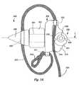
- FIG. 3Ais a side view of an embodiment of an implant in accordance with the present invention having a distraction guide, a spacer, a brace, and a binder associated with the brace and fixable in position by a capture device.
- FIG. 3Bis a side view of an alternative embodiment of an implant in accordance with the present invention including a brace wall having recesses for receiving lobes of a capture device.
- FIG. 3Cis a side view of still another embodiment of an implant in accordance with the present invention including a capture device having a spring-loaded cam for securing a binder against a brace wall.
- FIG. 3Dis a side view of a still further embodiment of an implant in accordance with the present invention including a capture device having dual spring-loaded cams for securing a binder in position.
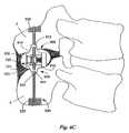
- FIG. 4Ais an end view of the implant of FIG. 3A positioned between adjacent spinous processes.
- FIG. 4Bis an end view of the implant of FIG. 3A positioned between adjacent spinous processes.
- FIG. 4Cis an end view of the implant of FIG. 3A positioned between adjacent spinous processes wherein the spinous processes are surgically modified to receive a binder.
- FIG. 5is an end view of an alternative embodiment of an implant in accordance with the present invention having a binder that varies in shape along the binder's length.
- FIG. 6Ais an end view of the implant of FIG. 5 positioned between adjacent spinous processes.
- FIG. 6Bis an opposite end view of the implant of FIG. 6A .
- FIG. 6Cis an end view of still another embodiment of an implant in accordance with the present invention having a cord for a binder.
- FIG. 7Ais a side view of an embodiment of an implant in accordance with the present invention including a wing associated with the distraction guide to further limit or block movement of the implant.
- FIG. 7Bis a partial cross-sectional side view of an alternative embodiment of an implant in accordance with the present invention include an extendable wing associated with the distraction guide, the extendable wing being in a retracted position.
- FIG. 7Cis a partial cross-sectional side view of the implant of FIG. 7B wherein the extendable wing is in an extended position.
- FIG. 7Dis a partial cross-sectional side view of still another embodiment of an implant in accordance with the present invention including a spring-loaded wing associated with the distraction guide, the wing being in an extended position.
- FIG. 7Eis a partial cross-sectional side view of the implant of FIG. 7D wherein the spring-loaded wing is in a collapsed position.
- FIG. 8is a top view of two implants in accordance with an embodiment of the present invention positioned between the spinous processes of adjacent vertebrae, one of the implants having a binder arranged around the adjacent spinous processes.
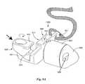
- FIG. 9Ais a perspective view of a further embodiment of an implant in accordance with the present invention having a distraction guide, a spacer, a brace, and a binder associated with the brace and fixable in position by a capture device.
- FIG. 9Bis a perspective view the implant of FIG. 9A wherein the capture device is arranged to secure a binder between the capture device and the brace.
- FIG. 9Cis a side view of the implant of FIGS. 9A and 9B .
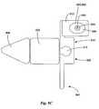
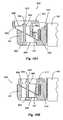
- FIG. 10Ais a cross-sectional top view of a binder loosely positioned within the capture device of the implant of FIGS. 9A and 9B .
- FIG. 10Bis a cross-sectional top view of the binder secured to the brace by the capture device of the implant of FIGS. 9A and 9B .
- FIG. 10Cis a cross-sectional top view of a binder loosely positioned within an alternative embodiment of a capture device of the implant of FIGS. 9A and 9B .
- FIG. 10Dis a cross-sectional top view of the binder and capture device of FIG. 10C wherein the binder is secured to the brace
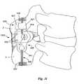
- FIG. 11is an end view of the implant of FIGS. 9A and 9B positioned between adjacent spinous processes.
- FIG. 12is a block diagram illustrating a method of surgically implanting an implant.
- FIG. 1is a perspective view of an implant as described in U.S. Pat. No. 6,695,842 to Zucherman, et al., incorporated herein by reference.
- the implant 100has a main body 101 .
- the main body 101includes a spacer 102 , a first wing 108 , a lead-in tissue expander 106 (also referred to herein as a distraction guide) and an alignment track 103 .
- the main body 101is inserted between adjacent spinous processes.
- the main body 101remains (where desired) in place without attachment to the bone or ligaments.
- the distraction guide 106includes a tip from which the distraction guide 106 expands, the tip having a diameter sufficiently small such that the tip can pierce an opening in an interspinous ligament and/or can be inserted into a small initial dilated opening.
- the diameter and/or cross-sectional area of the distraction guide 106then gradually increases until it is substantially similar to the diameter of the main body 101 and spacer 102 .
- the tapered front endeases the ability of a physician to urge the implant 100 between adjacent spinous processes. When urging the main body 101 between adjacent spinous processes, the front end of the distraction guide 106 distracts the adjacent spinous processes and dilates the interspinous ligament so that a space between the adjacent spinous processes is approximately the diameter of the spacer 102 .
- the shape of the spacer 102is such that for purposes of insertion between the spinous processes, the spinous processes need not be altered or cut away in order to accommodate the spacer 102 . Additionally, associated ligaments need not be cut away and there is little or no damage to the adjacent or surrounding tissues.
- the spacer 102is elliptically shaped in cross-section, and can swivel about a central body (also referred to herein as a shaft) extending from the first wing 108 so that the spacer 102 can self-align relative to the uneven surfaces of the spinous processes. Self-alignment can ensure that compressive loads are distributed across the surface of the bone.
- the spacer 102can have, for example, a diameter of six millimeters, eight millimeters, ten millimeters, twelve millimeters and fourteen millimeters. These diameters refer to the height by which the spacer distracts and maintains apart the spinous process.
- the selected heighti.e., diameter
- the major dimensionis transverse to the alignment of the spinous process, one above the other.
- the first wing 108has a lower portion 113 and an upper portion 112 .
- the upper portion 112is shaped to accommodate the anatomical form or contour of spinous processes (and/or laminae) of the L4 (for an L4-L5 placement) or L5 (for an L5-S1 placement) vertebra. The same shape or variations of this shape can be used to accommodate other motion segments.
- the lower portion 113can also be rounded to accommodate the spinous processes.
- the lower portion 113 and upper portion 112 of the first wing 108act as a stop mechanism when the implant 100 is inserted between adjacent spinous processes. The implant 100 cannot be inserted beyond the surfaces of the first wing 108 . Additionally, once the implant 100 is inserted, the first wing 108 can prevent side-to-side, or posterior-to-anterior movement of the implant 100 .
- the implant 100further includes an adjustable wing 150 (also referred to herein as a second wing).
- the adjustable wing 150has a lower portion 152 and an upper portion 153 . Similar to the first wing 108 , the adjustable wing 150 is designed to accommodate the anatomical form or contour of the spinous processes and/or lamina.
- the adjustable wing 150is secured to the main body 101 with a fastener 154 .
- the adjustable wing 150also has an alignment tab 158 . When the adjustable wing 150 is initially placed on the main body 101 , the alignment tab 158 engages the alignment track 103 . The alignment tab 158 slides within the alignment track 103 and helps to maintain the adjustable wing 150 substantially parallel with the first wing 108 .
- the adjustable wing 150also can prevent side-to-side, or posterior-to-anterior movement.
- FIG. 2Aillustrates an implant 100 positioned between adjacent spinous processes extending from vertebrae of the lumbar region.
- the implant 100is positioned between inferior articular processes 10 associated with the upper vertebrae and superior articular processes 12 associated with the lower vertebrae.
- the superspinous ligament 6connects the upper and lower spinous processes 2 , 4 .
- the implant 100can be positioned without severing or otherwise destructively disturbing the superspinous ligament 6 .
- the spacer 102 of the implant 100 of FIG. 2Ais shown in cross-section.
- the spacer 102defines a minimum space between adjacent spinous processes 2 , 4 .
- the spacer 102limits or blocks relative movement between the adjacent spinous processes 2 , 4 , limiting or blocking the collapse of the space between the spinous processes 2 , 4 .
- Such supportcan alleviate symptoms of degenerative disorders by preventing a reduction of the foraminal area and compression of the nerve roots, or by avoiding aggravation of a herniated disk, or by relieving other problems.
- the implant 100permits flexion, which in some degenerative disorders (for example in cases of spinal stenosis) can relieve some symptoms.
- the spacer 102can float between the spinous processes, held in position by the interspinous ligament 8 , and/or other tissues and structures associated with the spine.
- the ability to float between the spinous processes 2 , 4also permits varying degrees of rotation, as well as flexion.
- Implants as described in Zucherman '842thus have the advantage that they permit a greater degree of movement when compared with primary and supplementary spinal fusion devices.
- FIG. 3Aan embodiment of an implant 300 in accordance with the present invention is shown.
- the implant 300includes a distraction guide 306 , a spacer 302 , and a brace 308 .
- the spacer 302is rotatable about a central body 301 extending from the brace 302 , although in other embodiments the spacer 302 can be fixed is position.
- a binder 330can be fixedly connected with the brace 308 at a proximal end 332 of the binder 330 .
- the binder 330is flexible, or semi-flexible, and can be positioned around adjacent spinous processes so that the binder 308 engages the spinous processes during flexion of the spine. Once positioned around adjacent spinous processes, tension of the binder 330 can be set when the binder 330 is secured to the brace 308 so that relative movement of the adjacent spinous processes during flexion is limited or prevented, as desired.
- the brace 308can include a first end having a slot 341 through which the proximal end 332 of the binder 330 can be threaded and subsequently sutured, knotted or otherwise bound so that the proximal end 332 of the binder 330 cannot be drawn through the slot 341 .
- the proximal end 332can be looped or can include a connector, such as a clasp or other device, and can be fixed to the brace 308 via a fastener that engages the connector.
- proximal end 332 of the binder 330can be associated with the brace 308 so that tension can be applied to the binder 330 , and implants in accordance with the present invention are not intended to be limited to those schemes described in detail herein.
- the brace 308can include a height along the spine greater than a height of the spacer 302 so that movement along a longitudinal axis L in the direction of insertion is limited or blocked by the brace 308 when the brace 308 contacts the lateral surfaces of the spinous processes. In this way, the brace 308 can function similarly to the wing 108 of the above described implant 100 . In other embodiments, the brace 308 can have a height greater or smaller than as shown.
- a free end of the binder 330can be secured to the brace 308 by a capture device 320 associated with the brace 308 .
- the brace 308can include a flange 310 from which the capture device 320 can extend.
- the capture device 320comprises a rotatable cam 321 having a fastener 322 and one or more cut-outs 324 .
- a toolcan be mated with the cut-outs 324 and rotated to pivot the rotatable cam 321 .
- the eccentric shape of the cam 321causes a gap to close between the cam 321 and a wall 314 of the brace 330 from which the flange 310 extends.
- the rotation of the cam 321can pinch the binder 330 between the cam 321 and the wall 314 , defining a secured end 336 of the binder 330 .
- the fastener 322can be screwed (i.e., rotated) so that the fastener 322 is further seated, tightening against the cam 321 to fix the cam 321 in position.
- one or both of the wall 314 and the rotatable cam 321can include knurls, or some other texture (e.g., teeth) to prevent slippage (i.e., the slipping of the binder 330 between the cam 321 and the wall 314 ).
- the brace 308can further include a guide 312 , such as a channel or slot (a slot as shown) at a second end of the brace 308 to align the binder 330 with the capture device 320 .
- the binder 330can comprise a strap, ribbon, tether, cord, or some other flexible (or semi-flexible), and preferably threadable structure.
- the binder 330can be made from a biocompatible material.
- the binder 330can be made from a braided polyester suture material. Braided polyester suture materials include, for example, Ethibond, Ethiflex, Mersilene, and Dacron, and are nonabsorbable, having high tensile strength, low tissue reactivity and improved handling.
- the binder 330can be made from stainless steel (i.e., surgical steel), which can be braided into a tether or woven into a strap, for example.
- the binder 330can be made from some other material (or combination of materials) having similar properties.
- the distraction guide 306can optionally include a slot, bore, cut-out or other cavity 309 formed in the distraction guide 306 through which the binder 330 can be threaded or positioned.
- a cavitycan allow on-axis positioning of the binder 330 (i.e., the binder can be substantially aligned with the longitudinal axis L of the implant 300 ).
- capturing the binder 330 within a slot or borecan prevent or limit shifting of the distraction guide 306 relative to the binder 330 to further secure the implant 300 between the spinous processes.
- implants in accordance with the present inventionprovide significant benefits to a physician by simplifying an implantation procedure and reducing procedure time, while providing an implant that can limit or block flexion and extension of the spine.
- a physiciancan position an implant between adjacent spinous processes and can position a binder 330 connected with the brace 308 around the spinous processes without requiring the physician to measure an appropriate length of the binder 330 prior to implantation.
- the capture device 320allows the binder 330 to be secured to the brace 308 anywhere along a portion of the binder 330 , the portion being between a distal end 334 of the binder 330 and the proximal end 332 .
- the physiciancan secure the binder 330 to the brace 308 to achieve the desired range of movement (if any) of the spinous processes during flexion.
- the capture device 320 and brace 308can have alternative designs to that shown in FIG. 3A .
- a side view of an implant 400 in accordance with an alternative embodiment of the present inventionis shown in FIG. 3B , the implant 400 including a capture device 420 comprising a cam 421 positioned within a ring 426 having one or more lobes 423 corresponding with one or more recesses 413 in a wall 414 of the brace 408 .
- the binder 330is positioned between the capture device 420 and the brace 408 .
- the fastener 422 and cam 421can be rotated using an appropriate tool, with the cam 421 forcing the lobes 423 of the ring 426 to mate with the recesses 413 of the brace 408 , preventing the ring 426 from shifting in position and defining a secure end 336 of the binder 330 .
- Rotating the fastener 422rotates and optionally tightens down the cam 421 .
- Such a capture device 420can provide a physician a visual indication that the binder 330 is properly secured to the brace 408 , as well as preventing slippage.
- the implantcan include a capture device comprising a spring-loaded mechanism.
- FIG. 3Cillustrates an implant 500 including a capture device 520 comprising a single spring-loaded cam 521 pivotally connected with the flange 310 and biased to rotate in one direction.
- the distance between the pivot point of the cam 510 and the wall 314is sufficiently narrow that the rotation of the cam 521 in the direction of bias is blocked (or nearly blocked) by the wall 314 .
- the eccentricity of the cam 521is large enough that a maximum gap between the wall 314 and the cam 521 is sufficiently wide as to allow the binder 330 to be threaded between the cam 521 and the wall 314 .
- a physiciancan position the binder 330 between the cam 521 and the wall 514 by overcoming the spring-force of the spring-loaded cam 521 . Once the binder 330 is position as desired, the physician need only allow the bias force of the spring-loaded cam 520 to force the cam 521 against the wall 314 , so that the cam 521 pinches and secures the binder 330 between the cam 521 and the wall 314 .
- one or both of the cam 521 and the wall 314can be knurled or otherwise textured to limit or prevent slippage.
- the wall 314can optionally include a recess (not shown) to receive the cam 521 so that the binder 330 is pinched within the recess (similar to the lobe and recess arrangement of FIG. 3B ), thereby further limiting slippage.
- FIG. 3Dillustrates an implant 600 including a capture device 620 comprising dual spring-loaded cams 621 , the dual spring-loaded cams 621 being pivotally connected with the flange 310 .
- the dual spring-loaded cams 621are biased in opposition to one another so that the cams 621 abut one another, similar to cam cleats commonly used for securing rope lines on boats.
- the binder 330can be loosely positioned around the adjacent spinous processes and threaded between the cams 621 . Tension can be applied to the binder 330 , as desired, by drawing the binder 330 through the cams 621 .
- the force of the binder 330 being pulled through the cams 621can overcome the bias force to allow the binder 330 to be tightened, while releasing the binder 330 can define a secure end 336 of the binder 330 as the cams 621 swivel together.
- one or both of the cams 621can be knurled or otherwise textured to limit or prevent slippage.
- Embodiments of implantshave been described in FIGS. 3A-3D with some level of specificity; however, implants in accordance with the present invention should not be construed as being limited to such embodiments.
- Any number of different capture devicescan be employed to fix a binder to a brace by defining a secure end of the binder, and such capture devices should not be construed as being limited to capture devices including cams, as described above.
- the capture deviceneed only be a device that allows a physician to fit a binder having a generic size, or estimated size, around adjacent spinous processes with a desired level of precision in tension.
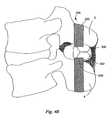
- FIGS. 4A and 4Bare an opposite end views of the implant of FIG. 3A positioned between adjacent spinous processes extending from vertebrae of the lumbar region.
- the contours of a space between adjacent spinous processescan vary between patients, and between motion segments.
- a rotatable spacer 302can rotate to best accommodate the shape of the space so that the implant 300 can be positioned as desired along the spinous processes. For example, it can be desirable to position the spacer 302 as close to the vertebral bodies as possible (or as close to the vertebral bodies as practicable) to provide improved support.
- the binder 330can be threaded through interspinous ligaments associated with motion segments (i.e., pairs of adjacent vertebrae and associated structures and tissues) above and below the targeted motion segment so that the binder 330 is arranged around the upper and lower spinous processes 2 , 4 .
- the binder 330can then be threaded through the slot 312 of the brace 308 and positioned between the capture device 320 and the brace wall 314 .
- a first tool(not shown) can be inserted into the incision formed to insert the implant 300 between the spinous processes 2 , 4 .
- the spacer 302can include a notch, similar to a notch 190 of the spacer 102 of FIG.
- the brace 308can include recesses, similar to recesses 192 of the first wing 108 of FIG. 1 , that can be engaged by the first tool for grasping and releasing the implant 300 during insertion. (See U.S. Pat. No. 6,712,819, which is incorporated herein by reference.) Alternatively, some other technique for grasping and releasing the implant 300 can be employed.
- a second toolsuch as a forked tool having spaced apart tines, can engage the cam 321 of the capture device 320 to rotate the cam 321 , thereby securing the binder 330 to the brace 308 .
- a hex wrenchcan tighten down the fastener 322 if desired.
- a single toolcan be employed to perform both the function of insertion of the implant 300 and rotation of the cam 321 , as depicted in the above referenced patent.
- the binder 330can then be trimmed so that the distal end 334 of the binder 330 does not extend undesirably away from the brace 308 .
- the spacer 302is rotated relative to the distraction guide 306 and the brace 308 .
- the brace 308can be positioned so that the binder 330 can be arranged around the upper and lower spinous processes 2 , 4 without twisting the binder 330 .
- the binder 330is positioned around the lower spinous process 4 , threaded or positioned at least partially within a slot 309 of the distraction guide 306 , and positioned around the upper spinous process 2 so that the binder 330 can be secured to the brace 308 , as described above.
- Implants in accordance with the present inventioncan enable a physician to limit or block flexion and extension in a targeted motion segment while minifying invasiveness of an implantation procedure (relative to implantation procedures of the prior art).
- implantscan also be used where more extensive implantation procedures are desired.
- FIG. 4Cit can be desired that the adjacent spinous processes 2 , 4 be surgically modified to receive the binder 330 , thereby insuring that the binder 330 does not shift or slide relative to the spinous processes 2 , 4 .
- the binder 330is threaded directly through the respective spinous processes 2 , 4 rather than through the interspinous ligaments of adjacent motion segments.
- the amount of bone removed from the spinous processes 2 , 4can be reduced where a cord or tether is used as a binder 330 rather than a strap. While such applications fall within the contemplated scope of implants and methods of implantation of the present invention, such application may not realize the full benefit that can be achieved using such implants due to the modification of the bone.
- the binder 430can comprise a first portion 431 formed as a strap for arrangement around one of the upper and lower spinous processes 2 , 4 , and that tapers to a second portion 433 formed as a cord.
- the distraction guide 406can include a bore 409 or other cavity for receiving the second portion 433 .
- a pad 436 of biocompatible materialcan be associated with the binder 430 , for example by slidably threading the binder 430 through a portion of the pad 436 , and the pad 436 can be arranged between the binder 430 and the respective spinous process 2 so that a load applied by the binder 430 is distributed across a portion of the surface of the spinous process 2 .
- the binder 330can be secured by the brace 708 .
- the brace 708 as shownis still another embodiment of a brace for use with implants of the present invention.
- the brace 708includes a capture device 720 comprising a clip including a spring-loaded button 721 having a first hole therethrough and a shell 723 in which the button 721 is disposed, the shell 723 having a second hole.
- a physiciandepresses the button 721 so that the first and second holes align.
- the binder 430can then be threaded through the holes, and the button 721 can be released so that the spring forces the holes to misalign, pinching the binder 430 and defining a secure end of the binder 430 .
- FIG. 6Cis an end view of a still further embodiment of an implant 800 in accordance with the present invention.
- the binder 530can comprise a cord.
- An upper pad 536 and a lower pad 538can be slidably associated with the binder 530 and arranged so that a load applied by the binder 530 is distributed across a portion of the upper and lower spinous processes 2 , 4 .
- such an embodimentcan include a brace 808 having a substantially different shape than braces previously described. It should be noted that the brace 808 of FIG.
- the footprint of the brace 808is reduced by shaping the wall 814 of the brace 808 to taper at an upper end to form a guide 812 for aligning the binder 530 and to taper at a lower end to an eyelet 841 for capturing a proximal end 532 of the binder 530 .
- the brace 808includes a height from eyelet 841 to guide 812 such that movement of the implant 800 in the direction of insertion is blocked or limited by the brace 808 .
- implants in accordance with the present inventioncan optionally further include a second wing for limiting or blocking movement in the direction opposite insertion. Inclusion of such a structure can ensure that the implant remains in position, for example where the binder slips out of a slot of the distraction guide, or where the binder becomes unsecured.
- an implant in accordance with an embodimentcan include a second wing 450 connected with the distraction guide 406 of the implant 900 by a fastener 454 .
- the second wing 450is similar to the second wing 150 described above in reference to FIG. 1 .
- the second wing 450can include an alignment tab 458 allowing a position of the second wing 450 to be adjusted along a longitudinal axis L of the implant 900 , and a fastener 454 (for example a hex headed bolt) for affixing the second wing 450 to the implant 900 in the position along the longitudinal axis L desired.
- the distraction guide 406can include an alignment groove (not shown) corresponding to the alignment tab 458 .
- the alignment tab 458fits within, and is movable along, the alignment groove so that a contact surface 455 of the second wing 450 can be arranged as desired.
- the second wing 450includes a substantially planar contact surface arranged so that the contact surface 455 of the second wing 450 is perpendicular to the longitudinal axis L.
- the contact surface 455need not be planar, and can be shaped and oriented to roughly correspond with a contact surface of the upper and lower spinous processes.
- a contact surface 315 of the binder 308can be shaped and oriented to roughly correspond with a contact surface of the upper and lower spinous processes.
- the upper portion 453 and the lower portion 452 of the second wing 450do not extend from the distraction guide 406 as substantially as the upper portion 153 and lower portion 152 of the second wing 150 of FIG. 1 .
- the second wing 450includes a height H along the spine smaller than that of the second wing 150 of FIG. 1 . It has been observed that benefits can be gained by including a wing 450 , though the wing 450 does not extend from the distraction guide 406 as significantly as shown in FIG. 1 (i.e., the wing 450 includes “nubs” extending above and/or below the height of the spacer 302 ). Such wings 450 will also be referred to herein as winglets. Including a second wing 450 having an overall height along the spine smaller than that of FIG. 1 can limit movement along the longitudinal axis without interfering with (or being interfered by) the arrangement of the binder 330 .
- implants in accordance with the present inventioncan include a second wing (or an upper portion and/or lower portion) extendable from the distraction guide.
- a second wingor an upper portion and/or lower portion
- implants 1000 in accordance with the present inventioncan include a distraction guide 506 having a selectably extendable upper portion 553 and lower portion 552 disposed within a cavity of the distraction guide 506 .
- the upper and lower portions 553 , 552can be extended by actuating a nut, knob or other mechanism operably associated with a gear 556 so that the gear 556 rotates.
- the teeth of the gear 556engage teeth of the upper and lower portions 553 , 552 , causing the upper and lower portions 553 , 552 to extend sufficiently that the upper and lower portions 553 , 552 form winglets for preventing motion of the implant 1000 in a direction opposite insertion (shown in FIG. 7C ). Rotating the gear 556 in an opposite direction can retract the upper and lower portions 553 , 552 .
- implants 1100 in accordance with the present inventioncan include spring-loaded upper and/or lower portions 653 , 652 such as shown in FIGS. 7D and 7E .
- the upper and lower portions 653 , 652can be fin-shaped, having sloping forward surfaces 655 , 654 and being spring-biased to an extended position, as shown in FIG. 7D .
- the spinous processes and/or related tissuescan contact the forward surface 655 , 654 of the upper and lower portions 653 , 652 , causing the upper and lower portions 653 , 652 to pivot about respective hinge points 657 , 656 and collapse into cavities disposed within the distraction guide 606 , as shown in FIG.
- the upper and lower portions 653 , 652re-extend out of the distraction guide 650 .
- a slot and pin mechanism 660 , 661 or other mechanismcan lock the upper and lower portion 653 , 652 in place once extended, disallowing over-extension of the upper and lower portion 653 , 652 in the direction of bias.
- the extended upper and lower portions 653 , 652limit or block movement of the implant 1100 in an a direction opposite insertion.
- implants in accordance with the present inventioncan optionally employ some other additional mechanism for limiting or blocking motion along the longitudinal axis of the implant.
- Mechanisms shown and described in FIGS. 7A-7Eare merely provided as examples of possible mechanisms for use with such implants, and are not intended to be limiting.
- FIG. 8is a top-down view of still another embodiment of an implant in accordance with the present invention including a brace 708 arranged at an angle along the spinous process relative to the longitudinal axis L of the implant 1200 .
- the brace 708is arranged at such an angle to roughly correspond to a general shape of the adjacent spinous processes. Such a general shape can commonly be found in spinous processes extending from vertebrae of the cervical and thoracic region, for example.
- the implant 1200further includes a second wing 752 extending from distraction guide 706 at an angle roughly corresponding to a general shape of the adjacent spinous processes. Identical implants 1200 , one above the other, are shown.
- the lower implant 1200includes a binder 330 arranged around the adjacent spinous processes (only the upper spinous process is shown) and positioned in a slot 309 of the distraction guide 706 .
- the binder 330includes a capture device 320 for securing the binder 330 to the brace 708 , and a channel formed by guides 712 on the brace 708 for aligning the binder 330 with the capture device 320 .
- the brace wallincludes a recess 717 to accommodate rotation of the rotatable spacer 302 .
- the implantscan include fixed spacers, for example integrally formed with the brace 708 and the distraction guide 706 .
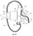
- FIGS. 9A and 9Bare perspective views, and FIG. 9C is a side view of a still further embodiment of an implant in accordance with the present invention.
- the implant 1300includes a distraction guide 806 , a rotatable spacer 402 , and a brace 908 .
- a binder 330can be fixedly connected with the brace 908 at a proximal end 332 of the binder 330 .
- tension of the binder 330can be set when the binder 330 is secured to the brace 908 so that relative movement of the adjacent spinous processes during flexion is limited or prevented, as desired.
- the brace 908can include a first end having an eyelet 941 through which the proximal end 332 of the binder 330 can be threaded and subsequently sutured, knotted or otherwise bound, or alternatively looped through the eyelet 941 and secured to itself (e.g., using a clasp) so that the proximal end 332 of the binder 330 cannot be drawn through the eyelet 941 .
- a claspe.g., a clasp
- a free end of the binder 330can be secured to the brace 908 by a capture device 820 associated with the brace 908 .
- the capture device 820 of FIGS. 9A-11is arranged at a second end of the brace 908 opposite the eyelet 941 , rather than approximately centered along the brace wall 914 .
- the brace 908can optionally include a locking pin hole 915 that can be engaged by a locking pin of an insertion instrument (not shown), for example as described in U.S. Pat. No. 6,712,819 to Zucherman, et al., incorporated herein by reference.
- the brace wall 914can optionally include one or more holes 916 (shown in FIG. 11 ) adapted to receive alignment pins of such an insertion instrument, and the spacer 402 can include a spacer engagement hole adapted to receive a spacer engagement pin of such an insertion instrument.
- the spacer 402can rotate and/or swivel about a central body 917 without impedance from the spacer engagement pin.
- Such an arrangementcan provide a physician additional control over the positioning of the implant 1300 , although in other embodiments the spacer 402 need not include an engagement hole.
- Arranging the captured device 820 at a second end of the brace 908can allow an insertion instrument, having a configuration as described in Zucherman '819 or having some other configuration, to releasably engage the implant 1300 to assist in implantation without interference from the capture device 820 .
- the distraction guide 806 of the implant 1300can be wedge-shaped, as described above, or approximately conical, as shown in FIGS. 9A-9C , and can include a slot 809 disposed through the distraction guide 806 and adapted to receive the binder 330 during implantation.
- the rotatable spacer 402can be elliptical in cross-section, or otherwise shaped, and can rotate relative to the distraction guide 806 to roughly conform with a contour of a space between the targeted adjacent spinous processes.
- the capture device 820is shown in cross-section in FIGS. 10A and 10B .
- the capture device 820can comprise, for example, two pieces slidably associated with one another by an adjustable fastener 822 (as shown, the adjustable fastener is a hex screw).
- a fixed piece 821 of the capture devicecan extend from the brace wall 914 .
- the fixed piece 821can include a beveled surface 823 that can function as a ramp.
- a slidable piece 827 of the capture devicecan be slidably associated with the fixed piece 821 , and can likewise included a beveled surface 829 positioned in opposition to the beveled surface 823 of the fixed piece 821 .
- the slidable piece 827is associated with the fixed piece 821 via an adjustable fastener 822 .
- the fastener 822can be positioned within slots 890 , 892 of the fixed piece 821 and the slidable piece 827 and can include a threaded shaft 880 , a head 882 , and a nut 884 .
- the head 882 of the fastener 822can engage an anterior surface 894 of the fixed piece 821 and the nut 884 can be threaded onto the threaded shaft 880 so that the nut 884 can engage a posterior surface 896 of the slidable piece 827 .
- the slidable piece 827is free to slide along the beveled surface 823 of the fixed piece 821 until both the nut 884 engages the posterior surface 896 and the head 882 engages the anterior surface 894 , blocking further movement in one direction.
- the distance between the anterior surface 894 and the posterior surface 896increases or decreases as the slidable piece 827 slides along the beveled surface 823 and a distance between a capture surface 898 of the slidable piece 827 and the brace wall 914 likewise increases or decreases.
- the maximum distance the slidable piece 827 can travelcan be defined by the distance between the nut 884 and the head 882 .
- a physiciancan adjust the maximum distance by rotating the nut 884 so that the nut 884 travels closer to, or farther from the head 882 along the threaded shaft 880 , possibly urging the capture surface 898 toward the brace wall 914 .
- the physiciancan set the maximum distance so that the free end of the binder 330 can be threaded between the capture surface 898 and the brace wall 914 . As shown in FIG.
- the physiciancan then adjust the fastener 822 so that the posterior surface 896 and the anterior surface 894 are urged together, the maximum distance decreases and the distance between the capture surface 898 and the brace wall 914 decreases, thereby pinching the binder 330 between the capture surface 898 and the brace wall 914 and defining a secure end of the binder 330 .
- one or both of the capture surface 898 and the brace wall 914can include texture so that the binder 330 is further prevented from sliding when the binder 330 is placed under increasing tension (e.g., during flexion).
- the slidable piece 827can optionally further include a guide 912 extending from the slidable piece 827 so that the guide 912 overlaps a portion of the brace 908 .
- the guide 912can extend, for example, a distance roughly similar to the maximum distance between the capture surface 898 and the brace wall 914 , and can help ensure that the binder 330 is captured between the capture surface 898 and the brace wall 914 .
- the capture device 820 of FIGS. 9A-10Bcan include some other shape or configuration and still fall within the contemplated scope of the invention.
- the fastenerneed not include a nut. In one embodiment, shown in FIGS.
- the fastener 922can include a threaded shaft 980 associated with a sleeve 984 . As one of the threaded shaft 980 and the sleeve 984 is rotated, the distance between a head 982 of the threaded shaft 980 and the head 985 of the sleeve 984 can decrease or increase. In still other embodiments, the fastener need not include a threaded shaft, but rather can include a smooth shaft having a retaining clip frictionally associated with the smooth shaft.
- a threaded shaftbut rather can include a smooth shaft having a retaining clip frictionally associated with the smooth shaft.
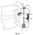
- FIG. 11is an end view of the implant 1300 of FIGS. 9A-10D positioned between adjacent spinous processes.
- the binder 530is a cord, but in other embodiments can have some other geometry.
- a pad 536can be arranged along a contact surface of the respective spinous process so that a load applied to the contact surface by the tension in the binder 530 can be distributed across a portion of the contact surface wider than the binder 530 , thereby reducing stress on the portion.
- the capture device 820is arranged so that the slidable piece 827 is posteriorly located relative to the fixed piece 821 .
- a fastener 822can be accessed by the physician using a substantially posterior approach.
- a method of surgically implanting an implant 1300 in accordance with an embodiment as described above in FIGS. 9A-11 of the present inventionis shown as a block diagram in FIG. 12 .
- the methodcan include forming an incision at the target motion segment, and enlarging the incision to access the target motion segment (Step 100 ).
- the interspinous ligament between targeted adjacent spinous processescan then be distracted by piercing or displacing the interspinous ligament with the distraction guide 106 (Step 102 ) and urging the implant 1300 between the adjacent spinous processes (Step 104 ).
- the spacer 302can be positioned between the spinous processes such that the spacer 302 can rotate to assume a preferred position between the spinous processes (Step 106 ).
- the binder 330can be threaded between interspinous ligaments of adjacent motion segments so that the targeted adjacent spinous processes are disposed within a loop formed by the binder 330 (Step 108 ).
- the physiciancan then thread the binder 330 between the capture surface 898 of the capture device 820 and the brace wall 914 (Step 110 ).
- Step 112the physician can adjust the fastener 822 of the capture device 820 so that the binder 330 is secured between the captured surface 898 and the brace wall 914 (Step 114 ).
- the incisioncan subsequently be closed (Step 116 ).
- the implantcan be fabricated from medical grade metals such as titanium, stainless steel, cobalt chrome, and alloys thereof, or other suitable implant material having similar high strength and biocompatible properties. Additionally, the implant can be at least partially fabricated from a shape memory metal, for example Nitinol, which is a combination of titanium and nickel. Such materials are typically radiopaque, and appear during x-ray imaging, and other types of imaging. Implants in accordance with the present invention, and/or portions thereof can also be fabricated from somewhat flexible and/or deflectable material. In these embodiments, the implant and/or portions thereof can be fabricated in whole or in part from medical grade biocompatible polymers, copolymers, blends, and composites of polymers.
- a copolymeris a polymer derived from more than one species of monomer.
- a polymer compositeis a heterogeneous combination of two or more materials, wherein the constituents are not miscible, and therefore exhibit an interface between one another.
- a polymer blendis a macroscopically homogeneous mixture of two or more different species of polymer.
- Many polymers, copolymers, blends, and composites of polymersare radiolucent and do not appear during x-ray or other types of imaging. Implants comprising such materials can provide a physician with a less obstructed view of the spine under imaging, than with an implant comprising radiopaque materials entirely. However, the implant need not comprise any radiolucent materials.
- PEEKpolyetheretherketone
- PEKKpolyetherketoneketone
- PEEKis proven as a durable material for implants, and meets the criterion of biocompatibility.
- Medical grade PEEKis available from Victrex Corporation of Lancashire, Great Britain under the product name PEEK-OPTIMA.
- Medical grade PEKKis available from Oxford Performance Materials under the name OXPEKK, and also from CoorsTek under the name BioPEKK. These medical grade materials are also available as reinforced polymer resins, such reinforced resins displaying even greater material strength.
- the implantcan be fabricated from PEEK 450G, which is an unfilled PEEK approved for medical implantation available from Victrex.
- PEEK 450Ghas the following approximate properties:
- the implant and/or portions thereofcan be formed by extrusion, injection, compression molding and/or machining techniques.
- Fillerscan be added to a polymer, copolymer, polymer blend, or polymer composite to reinforce a polymeric material. Fillers are added to modify properties such as mechanical, optical, and thermal properties. For example, carbon fibers can be added to reinforce polymers mechanically to enhance strength for certain uses, such as for load bearing devices.
- other grades of PEEKare available and contemplated for use in implants in accordance with the present invention, such as 30% glass-filled or 30% carbon-filled grades, provided such materials are cleared for use in implantable devices by the FDA, or other regulatory body. Glass-filled PEEK reduces the expansion rate and increases the flexural modulus of PEEK relative to unfilled PEEK.
- Carbon-filled PEEKis known to have enhanced compressive strength and stiffness, and a lower expansion rate relative to unfilled PEEK. Carbon-filled PEEK also offers wear resistance and load carrying capability.
- the implantcan be comprised of polyetherketoneketone (PEKK).
- PEKKpolyetherketoneketone
- Other material that can be usedinclude polyetherketone (PEK), polyetherketoneetherketoneketone (PEKEKK), polyetheretherketoneketone (PEEKK), and generally a polyaryletheretherketone.
- PEKpolyetherketone
- PEKEKKpolyetherketoneetherketoneketone
- PEEKKpolyetheretherketoneketone
- other polyketonescan be used as well as other thermoplastics.
- the bindercan be made from a biocompatible material.
- the bindercan be made from a braided polyester suture material.
- Braided polyester suture materialsinclude, for example, Ethibond, Ethiflex, Mersilene, and Dacron, and are nonabsorbable, having high tensile strength, low tissue reactivity and improved handling.
- the bindercan be made from stainless steel (i.e., surgical steel), which can be braided into a tether or woven into a strap, for example.
- the bindercan be made from some other material (or combination of materials) having similar properties.
Landscapes
- Health & Medical Sciences (AREA)
- Orthopedic Medicine & Surgery (AREA)
- Life Sciences & Earth Sciences (AREA)
- Neurology (AREA)
- Surgery (AREA)
- Heart & Thoracic Surgery (AREA)
- Engineering & Computer Science (AREA)
- Biomedical Technology (AREA)
- Nuclear Medicine, Radiotherapy & Molecular Imaging (AREA)
- Medical Informatics (AREA)
- Molecular Biology (AREA)
- Animal Behavior & Ethology (AREA)
- General Health & Medical Sciences (AREA)
- Public Health (AREA)
- Veterinary Medicine (AREA)
- Prostheses (AREA)
Abstract
Description
| Property | Value | ||
| Density | 1.3 | g/cc |
| Rockwell M | 99 | |
| Rockwell R | 126 |
| Tensile Strength | 97 | MPa | ||
| Modulus of Elasticity | 3.5 | GPa | ||
| Flexural Modulus | 4.1 | GPa | ||
PEEK 450G has appropriate physical and mechanical properties and is suitable for carrying and spreading a physical load between the adjacent spinous processes. The implant and/or portions thereof can be formed by extrusion, injection, compression molding and/or machining techniques.
Claims (27)
Priority Applications (29)
| Application Number | Priority Date | Filing Date | Title |
|---|---|---|---|
| US11/095,440US20060064165A1 (en) | 2004-09-23 | 2005-03-31 | Interspinous process implant including a binder and method of implantation |
| US11/095,680US7909853B2 (en) | 2004-09-23 | 2005-03-31 | Interspinous process implant including a binder and method of implantation |
| EP05798791AEP1804732B1 (en) | 2004-09-23 | 2005-09-23 | Interspinous process implant including a binder |
| JP2007533639AJP4667465B2 (en) | 2004-09-23 | 2005-09-23 | Interspinous process graft containing binder |
| ES05798791TES2372295T3 (en) | 2004-09-23 | 2005-09-23 | IMPLANT OF INTERESPINOUS PROLONGATIONS THAT INCLUDE A BINDER AND IMPLEMENTATION METHOD. |
| KR1020077009238AKR20070097412A (en) | 2004-09-23 | 2005-09-23 | Binder-Included Implants and Implantation Methods Between Spines |
| AU2005286630AAU2005286630A1 (en) | 2004-09-23 | 2005-09-23 | Interspinous process implant including a binder and method of implantation |
| AT05798791TATE524142T1 (en) | 2004-09-23 | 2005-09-23 | PROCESSUS INTERSPINOSUS IMPLANT WITH A BINDER |
| CA002582527ACA2582527A1 (en) | 2004-09-23 | 2005-09-23 | Interspinous process implant with binder and method |
| MX2007003406AMX2007003406A (en) | 2004-09-23 | 2005-09-23 | Interspinous process implant including a binder and method of implantation. |
| PCT/US2005/034057WO2006034423A2 (en) | 2004-09-23 | 2005-09-23 | Interspinous process implant including a binder and method of implantation |
| CN2005800401858ACN101068513B (en) | 2004-09-23 | 2005-09-23 | Intervertebral protrusion implant comprising a strap |
| US11/668,217US8012209B2 (en) | 2004-09-23 | 2007-01-29 | Interspinous process implant including a binder, binder aligner and method of implantation |
| IL181978AIL181978A0 (en) | 2004-09-23 | 2007-03-15 | Interspinous process implant including a binder and method of implantation |
| US11/806,528US20080021468A1 (en) | 2002-10-29 | 2007-05-31 | Interspinous process implants and methods of use |
| US11/806,526US8221463B2 (en) | 2002-10-29 | 2007-05-31 | Interspinous process implants and methods of use |
| US11/768,224US20080065213A1 (en) | 2002-10-29 | 2007-06-26 | Interspinous process implants and methods of use |
| US11/768,222US8092535B2 (en) | 2002-10-29 | 2007-06-26 | Interspinous process implants and methods of use |
| US11/768,223US20080065212A1 (en) | 2002-10-29 | 2007-06-26 | Interspinous process implants and methods of use |
| US11/771,092US8454659B2 (en) | 2002-10-29 | 2007-06-29 | Interspinous process implants and methods of use |
| US11/770,943US20080051898A1 (en) | 2002-10-29 | 2007-06-29 | Interspinous process implants and methods of use |
| US11/771,046US20080051899A1 (en) | 2002-10-29 | 2007-06-29 | Interspinous process implants and methods of use |
| US11/770,915US8007537B2 (en) | 2002-10-29 | 2007-06-29 | Interspinous process implants and methods of use |
| US11/770,924US20080046081A1 (en) | 2002-10-29 | 2007-06-29 | Interspinous process implants and methods of use |
| US11/770,931US20080065214A1 (en) | 2002-10-29 | 2007-06-29 | Interspinous process implants and methods of use |
| US11/771,099US7662187B2 (en) | 2002-10-29 | 2007-06-29 | Interspinous process implants and methods of use |
| US11/771,087US8894686B2 (en) | 2002-10-29 | 2007-06-29 | Interspinous process implants and methods of use |
| US11/770,934US20080221692A1 (en) | 2002-10-29 | 2007-06-29 | Interspinous process implants and methods of use |
| US11/923,814US20080046087A1 (en) | 2004-09-23 | 2007-10-25 | Interspinous process implant including a binder and method of implantation |
Applications Claiming Priority (2)
| Application Number | Priority Date | Filing Date | Title |
|---|---|---|---|
| US61246504P | 2004-09-23 | 2004-09-23 | |
| US11/095,680US7909853B2 (en) | 2004-09-23 | 2005-03-31 | Interspinous process implant including a binder and method of implantation |
Related Parent Applications (2)
| Application Number | Title | Priority Date | Filing Date |
|---|---|---|---|
| US10/816,173Continuation-In-PartUS7549999B2 (en) | 2002-10-29 | 2004-04-01 | Interspinous process distraction implant and method of implantation |
| US11/378,108Continuation-In-PartUS7749252B2 (en) | 2002-10-29 | 2006-03-17 | Interspinous process implant having deployable wing and method of implantation |
Related Child Applications (5)
| Application Number | Title | Priority Date | Filing Date |
|---|---|---|---|
| US11/095,440Continuation-In-PartUS20060064165A1 (en) | 2002-10-29 | 2005-03-31 | Interspinous process implant including a binder and method of implantation |
| US11/668,217Continuation-In-PartUS8012209B2 (en) | 2004-09-23 | 2007-01-29 | Interspinous process implant including a binder, binder aligner and method of implantation |
| US11/806,526Continuation-In-PartUS8221463B2 (en) | 2002-10-29 | 2007-05-31 | Interspinous process implants and methods of use |
| US11/806,528Continuation-In-PartUS20080021468A1 (en) | 2002-10-29 | 2007-05-31 | Interspinous process implants and methods of use |
| US11/923,814ContinuationUS20080046087A1 (en) | 2004-09-23 | 2007-10-25 | Interspinous process implant including a binder and method of implantation |
Publications (2)
| Publication Number | Publication Date |
|---|---|
| US20060064166A1 US20060064166A1 (en) | 2006-03-23 |
| US7909853B2true US7909853B2 (en) | 2011-03-22 |
Family
ID=36075090
Family Applications (2)
| Application Number | Title | Priority Date | Filing Date |
|---|---|---|---|
| US11/095,680Expired - Fee RelatedUS7909853B2 (en) | 2002-10-29 | 2005-03-31 | Interspinous process implant including a binder and method of implantation |
| US11/923,814AbandonedUS20080046087A1 (en) | 2004-09-23 | 2007-10-25 | Interspinous process implant including a binder and method of implantation |
Family Applications After (1)
| Application Number | Title | Priority Date | Filing Date |
|---|---|---|---|
| US11/923,814AbandonedUS20080046087A1 (en) | 2004-09-23 | 2007-10-25 | Interspinous process implant including a binder and method of implantation |
Country Status (1)
| Country | Link |
|---|---|
| US (2) | US7909853B2 (en) |
Cited By (22)
| Publication number | Priority date | Publication date | Assignee | Title |
|---|---|---|---|---|
| US20080108993A1 (en)* | 2006-10-19 | 2008-05-08 | Simpirica Spine, Inc. | Methods and systems for deploying spinous process constraints |
| US20080262549A1 (en)* | 2006-10-19 | 2008-10-23 | Simpirica Spine, Inc. | Methods and systems for deploying spinous process constraints |
| US20090182379A1 (en)* | 2005-09-21 | 2009-07-16 | Abbott Spine | Flexible tie fastening system |
| US20090204151A1 (en)* | 2008-02-07 | 2009-08-13 | Scott Bracken | Spinal implant device, procedure and system |
| US20090264932A1 (en)* | 2006-10-19 | 2009-10-22 | Simpirica Spine, Inc. | Methods and systems for constraint of multiple spine segments |
| US20100211102A1 (en)* | 2007-09-25 | 2010-08-19 | Karl Pierre Belliard | Device for clamping two portions of a braid and an intervertebral implant comprising a spacer, a braid, and such a clamping device |
| US20120165872A1 (en)* | 2010-04-16 | 2012-06-28 | Simpirica Spine, Inc. | Methods and systems for constraint of multiple spine segments |
| US20130012995A1 (en)* | 2009-12-23 | 2013-01-10 | Qspine Limited | Interspinous Implant |
| US8454660B2 (en) | 2006-10-19 | 2013-06-04 | Simpirica Spine, Inc. | Methods and systems for laterally stabilized constraint of spinous processes |
| US20140148854A1 (en)* | 2012-11-28 | 2014-05-29 | Zimmer Spine, Inc. | Vertebral fixation system |
| US8864828B2 (en) | 2004-10-20 | 2014-10-21 | Vertiflex, Inc. | Interspinous spacer |
| US8900271B2 (en) | 2004-10-20 | 2014-12-02 | The Board Of Trustees Of The Leland Stanford Junior University | Systems and methods for posterior dynamic stabilization of the spine |
| US8932333B2 (en) | 2010-01-14 | 2015-01-13 | X-Spine Systems, Inc. | Modular interspinous fixation system and method |
| US9039742B2 (en) | 2004-10-20 | 2015-05-26 | The Board Of Trustees Of The Leland Stanford Junior University | Systems and methods for posterior dynamic stabilization of the spine |
| US9119680B2 (en) | 2004-10-20 | 2015-09-01 | Vertiflex, Inc. | Interspinous spacer |
| US9149306B2 (en) | 2011-06-21 | 2015-10-06 | Seaspine, Inc. | Spinous process device |
| US9155570B2 (en) | 2004-10-20 | 2015-10-13 | Vertiflex, Inc. | Interspinous spacer |
| US9662150B1 (en) | 2007-02-26 | 2017-05-30 | Nuvasive, Inc. | Spinal stabilization system and methods of use |
| US9987052B2 (en) | 2015-02-24 | 2018-06-05 | X-Spine Systems, Inc. | Modular interspinous fixation system with threaded component |
| US20190046244A1 (en)* | 2017-08-10 | 2019-02-14 | Ortho Development Corporation | Tether clamping assemblies and related methods and apparatus |
| US20190175223A1 (en)* | 2017-08-10 | 2019-06-13 | Ortho Development Corporation | Nesting tether clamping assemblies and related methods and apparatus |
| US10335207B2 (en) | 2015-12-29 | 2019-07-02 | Nuvasive, Inc. | Spinous process plate fixation assembly |
Families Citing this family (73)
| Publication number | Priority date | Publication date | Assignee | Title |
|---|---|---|---|---|
| US5836948A (en)* | 1997-01-02 | 1998-11-17 | Saint Francis Medical Technologies, Llc | Spine distraction implant and method |
| US6068630A (en)* | 1997-01-02 | 2000-05-30 | St. Francis Medical Technologies, Inc. | Spine distraction implant |
| US7178850B2 (en)* | 2005-02-09 | 2007-02-20 | Termax Corporation | Tethered fastener apparatus and method |
| US7850733B2 (en)* | 2004-02-10 | 2010-12-14 | Atlas Spine, Inc. | PLIF opposing wedge ramp |
| US8273129B2 (en)* | 2004-02-10 | 2012-09-25 | Atlas Spine, Inc. | PLIF opposing wedge ramp |
| US8523904B2 (en) | 2004-03-09 | 2013-09-03 | The Board Of Trustees Of The Leland Stanford Junior University | Methods and systems for constraint of spinous processes with attachment |
| US7458981B2 (en)* | 2004-03-09 | 2008-12-02 | The Board Of Trustees Of The Leland Stanford Junior University | Spinal implant and method for restricting spinal flexion |
| US9023084B2 (en) | 2004-10-20 | 2015-05-05 | The Board Of Trustees Of The Leland Stanford Junior University | Systems and methods for stabilizing the motion or adjusting the position of the spine |
| US8613747B2 (en) | 2004-10-20 | 2013-12-24 | Vertiflex, Inc. | Spacer insertion instrument |
| US8425559B2 (en)* | 2004-10-20 | 2013-04-23 | Vertiflex, Inc. | Systems and methods for posterior dynamic stabilization of the spine |
| US8123782B2 (en) | 2004-10-20 | 2012-02-28 | Vertiflex, Inc. | Interspinous spacer |
| US8277488B2 (en)* | 2004-10-20 | 2012-10-02 | Vertiflex, Inc. | Interspinous spacer |
| US8128662B2 (en) | 2004-10-20 | 2012-03-06 | Vertiflex, Inc. | Minimally invasive tooling for delivery of interspinous spacer |
| US7763074B2 (en)* | 2004-10-20 | 2010-07-27 | The Board Of Trustees Of The Leland Stanford Junior University | Systems and methods for posterior dynamic stabilization of the spine |
| US9161783B2 (en) | 2004-10-20 | 2015-10-20 | Vertiflex, Inc. | Interspinous spacer |
| US8012207B2 (en) | 2004-10-20 | 2011-09-06 | Vertiflex, Inc. | Systems and methods for posterior dynamic stabilization of the spine |
| US8409282B2 (en) | 2004-10-20 | 2013-04-02 | Vertiflex, Inc. | Systems and methods for posterior dynamic stabilization of the spine |
| US8945183B2 (en)* | 2004-10-20 | 2015-02-03 | Vertiflex, Inc. | Interspinous process spacer instrument system with deployment indicator |
| US8123807B2 (en)* | 2004-10-20 | 2012-02-28 | Vertiflex, Inc. | Systems and methods for posterior dynamic stabilization of the spine |
| US8317864B2 (en) | 2004-10-20 | 2012-11-27 | The Board Of Trustees Of The Leland Stanford Junior University | Systems and methods for posterior dynamic stabilization of the spine |
| US8241330B2 (en)* | 2007-01-11 | 2012-08-14 | Lanx, Inc. | Spinous process implants and associated methods |
| US9055981B2 (en)* | 2004-10-25 | 2015-06-16 | Lanx, Inc. | Spinal implants and methods |
| EP2219538B1 (en) | 2004-12-06 | 2022-07-06 | Vertiflex, Inc. | Spacer insertion instrument |
| US8128145B2 (en)* | 2005-02-09 | 2012-03-06 | Termax Corporation | Tethered fastener apparatus and method |
| PL377136A1 (en)* | 2005-09-19 | 2007-04-02 | Lfc Spółka Z Ograniczoną Odpowiedzialnością | Intervertebral space implant |
| US8845726B2 (en) | 2006-10-18 | 2014-09-30 | Vertiflex, Inc. | Dilator |
| US8187307B2 (en)* | 2006-10-19 | 2012-05-29 | Simpirica Spine, Inc. | Structures and methods for constraining spinal processes with single connector |
| US8974496B2 (en)* | 2007-08-30 | 2015-03-10 | Jeffrey Chun Wang | Interspinous implant, tools and methods of implanting |
| US20080167655A1 (en)* | 2007-01-05 | 2008-07-10 | Jeffrey Chun Wang | Interspinous implant, tools and methods of implanting |
| US9265532B2 (en)* | 2007-01-11 | 2016-02-23 | Lanx, Inc. | Interspinous implants and methods |
| US9247968B2 (en) | 2007-01-11 | 2016-02-02 | Lanx, Inc. | Spinous process implants and associated methods |
| WO2008124831A2 (en)* | 2007-04-10 | 2008-10-16 | Lee David M D | Adjustable spine distraction implant |
| AU2008241447B2 (en) | 2007-04-16 | 2014-03-27 | Vertiflex, Inc. | Interspinous spacer |
| US8142479B2 (en)* | 2007-05-01 | 2012-03-27 | Spinal Simplicity Llc | Interspinous process implants having deployable engagement arms |
| EP2142146A4 (en)* | 2007-05-01 | 2010-12-01 | Spinal Simplicity Llc | Interspinous implants and methods for implanting same |
| US8070779B2 (en)* | 2007-06-04 | 2011-12-06 | K2M, Inc. | Percutaneous interspinous process device and method |
| US20110172708A1 (en)* | 2007-06-22 | 2011-07-14 | Simpirica Spine, Inc. | Methods and systems for increasing the bending stiffness of a spinal segment with elongation limit |
| US20100036424A1 (en) | 2007-06-22 | 2010-02-11 | Simpirica Spine, Inc. | Methods and systems for increasing the bending stiffness and constraining the spreading of a spinal segment |
| EP2182864B1 (en)* | 2007-06-22 | 2016-06-08 | Empirical Spine, Inc. | Devices for controlled flexion restriction of spinal segments |
| US8308767B2 (en) | 2007-09-19 | 2012-11-13 | Pioneer Surgical Technology, Inc. | Interlaminar stabilization system |
| EP2923664B1 (en) | 2007-10-17 | 2019-01-02 | ARO Medical ApS | Systems and apparatuses for torsional stabilisation |
| US9750544B2 (en)* | 2007-11-02 | 2017-09-05 | Zimmer Biomet Spine, Inc. | Interspinous implants with deployable wing |
| US8202299B2 (en)* | 2008-03-19 | 2012-06-19 | Collabcom II, LLC | Interspinous implant, tools and methods of implanting |
| US9301788B2 (en) | 2008-04-10 | 2016-04-05 | Life Spine, Inc. | Adjustable spine distraction implant |
| EP2303163B1 (en)* | 2008-05-20 | 2011-11-23 | Zimmer Spine | System for stabilizing at least three vertebrae |
| WO2009149399A1 (en)* | 2008-06-06 | 2009-12-10 | Simpirica Spine, Inc. | Methods and apparatus for deploying spinous process constraints |
| EP2296567B1 (en)* | 2008-06-06 | 2014-03-12 | Simpirica Spine, Inc. | Apparatus for locking a band |
| WO2009149414A1 (en) | 2008-06-06 | 2009-12-10 | Simpirica Spine, Inc. | Methods and apparatus for locking a band |
| EP2323574B1 (en) | 2008-08-13 | 2012-02-15 | Synthes GmbH | Interspinous spacer assembly |
| US8062032B2 (en)* | 2008-10-23 | 2011-11-22 | Intrinsic Medical, Llc | Apparatus, system, and method for maxillo-mandibular fixation |
| CH700268A2 (en)* | 2009-01-21 | 2010-07-30 | Med Titan Spine Gmbh | Lumbar support relief. |
| WO2010104935A1 (en)* | 2009-03-10 | 2010-09-16 | Simpirica Spine, Inc. | Surgical tether apparatus and methods of use |
| EP2405840B1 (en) | 2009-03-10 | 2024-02-21 | Empirical Spine, Inc. | Surgical tether apparatus |
| WO2010104975A1 (en) | 2009-03-10 | 2010-09-16 | Simpirica Spine, Inc. | Surgical tether apparatus and methods of use |
| US8945184B2 (en)* | 2009-03-13 | 2015-02-03 | Spinal Simplicity Llc. | Interspinous process implant and fusion cage spacer |
| US9757164B2 (en) | 2013-01-07 | 2017-09-12 | Spinal Simplicity Llc | Interspinous process implant having deployable anchor blades |
| US9861399B2 (en) | 2009-03-13 | 2018-01-09 | Spinal Simplicity, Llc | Interspinous process implant having a body with a removable end portion |
| US8668719B2 (en) | 2009-03-30 | 2014-03-11 | Simpirica Spine, Inc. | Methods and apparatus for improving shear loading capacity of a spinal segment |
| US9149305B2 (en) | 2009-10-14 | 2015-10-06 | Latitude Holdings, Llc | Spinous process fixation plate and minimally invasive method for placement |
| US8740948B2 (en) | 2009-12-15 | 2014-06-03 | Vertiflex, Inc. | Spinal spacer for cervical and other vertebra, and associated systems and methods |
| US8821547B2 (en) | 2010-11-01 | 2014-09-02 | Warsaw Orthopedic, Inc. | Spinous process implant with a post and an enlarged boss |
| US8496689B2 (en) | 2011-02-23 | 2013-07-30 | Farzad Massoudi | Spinal implant device with fusion cage and fixation plates and method of implanting |
| US8425560B2 (en) | 2011-03-09 | 2013-04-23 | Farzad Massoudi | Spinal implant device with fixation plates and lag screws and method of implanting |
| US11812923B2 (en) | 2011-10-07 | 2023-11-14 | Alan Villavicencio | Spinal fixation device |
| KR101121667B1 (en)* | 2012-01-17 | 2012-03-09 | 김창국 | Interspinous spinal spacer |
| US9675303B2 (en) | 2013-03-15 | 2017-06-13 | Vertiflex, Inc. | Visualization systems, instruments and methods of using the same in spinal decompression procedures |
| AU2015256024B2 (en) | 2014-05-07 | 2020-03-05 | Vertiflex, Inc. | Spinal nerve decompression systems, dilation systems, and methods of using the same |
| US10034769B2 (en) | 2014-08-26 | 2018-07-31 | Atlas Spine, Inc. | Spinal implant device |
| WO2023158581A1 (en) | 2022-02-15 | 2023-08-24 | Boston Scientific Neuromodulation Corporation | Interspinous spacer and systems utilizing the interspinous spacer |
| US12133664B2 (en) | 2022-12-13 | 2024-11-05 | Spinal Simplicity, Llc | Medical implant |
| US12433646B2 (en) | 2023-02-21 | 2025-10-07 | Boston Scientific Neuromodulation Corporation | Interspinous spacer with actuator locking arrangements and methods and systems |
| CN116421259B (en)* | 2023-03-03 | 2025-09-09 | 河南科技大学 | Saw blade type mechanical arm capable of preventing nerve injury and application method thereof |
| US12390340B2 (en) | 2023-03-15 | 2025-08-19 | Boston Scientific Neuromodulation Corporation | Interspinous spacer with a range of deployment positions and methods and systems |
Citations (424)
| Publication number | Priority date | Publication date | Assignee | Title |
|---|---|---|---|---|
| US278097A (en) | 1883-05-22 | Wire-coupling | ||
| US1706431A (en) | 1923-03-16 | 1929-03-26 | Theodore H Wittliff | Furniture brace |
| US2456806A (en) | 1947-01-14 | 1948-12-21 | Erwin B Wolffe | Vaginal gauge |
| US2602902A (en) | 1950-02-14 | 1952-07-08 | Bendix Aviat Corp | Sweep amplitude control for magnetically deflected cathode-ray tubes |
| US2677369A (en) | 1952-03-26 | 1954-05-04 | Fred L Knowles | Apparatus for treatment of the spinal column |
| GB780652A (en) | 1954-04-30 | 1957-08-07 | Zimmer Orthopaedic Ltd | Improvements in or relating to apparatus for use in spinal fixation |
| US3123077A (en) | 1964-03-03 | Surgical suture | ||
| US3426364A (en) | 1966-08-25 | 1969-02-11 | Colorado State Univ Research F | Prosthetic appliance for replacing one or more natural vertebrae |
| US3643658A (en) | 1968-09-03 | 1972-02-22 | Straumann Inst Ag | Implants of titanium or a titanium alloy for the surgical treatment of bones |
| US3648691A (en) | 1970-02-24 | 1972-03-14 | Univ Colorado State Res Found | Method of applying vertebral appliance |
| US3654668A (en) | 1970-05-15 | 1972-04-11 | Arthur I Appleton | Wrapping device |
| US3678542A (en) | 1970-06-17 | 1972-07-25 | Ancra Corp | Cam buckle |
| US3867728A (en) | 1971-12-30 | 1975-02-25 | Cutter Lab | Prosthesis for spinal repair |
| US3875595A (en) | 1974-04-15 | 1975-04-08 | Edward C Froning | Intervertebral disc prosthesis and instruments for locating same |
| US4003376A (en) | 1975-08-25 | 1977-01-18 | Bio-Dynamics, Inc. | Apparatus for straightening the spinal column |
| US4011602A (en) | 1975-10-06 | 1977-03-15 | Battelle Memorial Institute | Porous expandable device for attachment to bone tissue |
| US4034418A (en) | 1975-05-26 | 1977-07-12 | The Governing Council Of The University Of Toronto | Artificial knee joint |
| US4047523A (en) | 1975-04-28 | 1977-09-13 | Downs Surgical Limited | Surgical sacral anchor implant |
| DE2821678A1 (en) | 1978-05-12 | 1979-11-22 | Sulzer Ag | IMPLANT THAT CAN BE INSERTED BETWEEN NEIGHBORING Vertebrae |
| US4219015A (en) | 1977-04-22 | 1980-08-26 | Institut Straumann Ag | Plates for osteosynthesis |
| US4257409A (en) | 1978-04-14 | 1981-03-24 | Kazimierz Bacal | Device for treatment of spinal curvature |
| US4309777A (en) | 1980-11-13 | 1982-01-12 | Patil Arun A | Artificial intervertebral disc |
| DE3113142A1 (en) | 1980-04-15 | 1982-01-14 | Politechnika Sląska im. Wincentego Pstrowskiego, Gliwice | Implant for the stable inner immobilization of the spine |
| US4349921A (en) | 1980-06-13 | 1982-09-21 | Kuntz J David | Intervertebral disc prosthesis |
| SU988281A1 (en) | 1981-06-26 | 1983-01-15 | За витель | Vertical column fixing device |
| US4369769A (en) | 1980-06-13 | 1983-01-25 | Edwards Charles C | Spinal fixation device and method |
| US4401112A (en) | 1980-09-15 | 1983-08-30 | Rezaian Seyed M | Spinal fixator |
| US4448191A (en) | 1981-07-07 | 1984-05-15 | Rodnyansky Lazar I | Implantable correctant of a spinal curvature and a method for treatment of a spinal curvature |
| US4455690A (en) | 1980-11-06 | 1984-06-26 | Homsy Charles A | Structure for in vivo implanation |
| US4479491A (en) | 1982-07-26 | 1984-10-30 | Martin Felix M | Intervertebral stabilization implant |
| US4501269A (en) | 1981-12-11 | 1985-02-26 | Washington State University Research Foundation, Inc. | Process for fusing bone joints |
| US4553273A (en) | 1983-11-23 | 1985-11-19 | Henry Ford Hospital | Vertebral body prosthesis and spine stabilizing method |
| US4554914A (en) | 1983-10-04 | 1985-11-26 | Kapp John P | Prosthetic vertebral body |
| US4570618A (en) | 1983-11-23 | 1986-02-18 | Henry Ford Hospital | Intervertebral body wire stabilization |
| US4573454A (en) | 1984-05-17 | 1986-03-04 | Hoffman Gregory A | Spinal fixation apparatus |
| US4599086A (en) | 1985-06-07 | 1986-07-08 | Doty James R | Spine stabilization device and method |
| US4599084A (en) | 1983-05-24 | 1986-07-08 | American Hospital Supply Corp. | Method of using biological tissue to promote even bone growth |
| US4604995A (en) | 1984-03-30 | 1986-08-12 | Stephens David C | Spinal stabilizer |
| US4611582A (en) | 1983-12-27 | 1986-09-16 | Wisconsin Alumni Research Foundation | Vertebral clamp |
| US4636217A (en) | 1985-04-23 | 1987-01-13 | Regents Of The University Of Minnesota | Anterior spinal implant |
| US4643178A (en) | 1984-04-23 | 1987-02-17 | Fabco Medical Products, Inc. | Surgical wire and method for the use thereof |
| US4643174A (en) | 1983-10-01 | 1987-02-17 | Tohru Horiuchi | Adjustable cervical spine corset and truck corset |
| US4657550A (en) | 1984-12-21 | 1987-04-14 | Daher Youssef H | Buttressing device usable in a vertebral prosthesis |
| US4685447A (en) | 1985-03-25 | 1987-08-11 | Pmt Corporation | Tissue expander system |
| US4686970A (en) | 1983-12-15 | 1987-08-18 | A. W. Showell (Surgicraft) Limited | Devices for spinal fixation |
| US4696290A (en) | 1983-12-16 | 1987-09-29 | Acromed Corporation | Apparatus for straightening spinal columns |
| US4714469A (en) | 1987-02-26 | 1987-12-22 | Pfizer Hospital Products Group, Inc. | Spinal implant |
| US4743256A (en) | 1985-10-04 | 1988-05-10 | Brantigan John W | Surgical prosthetic implant facilitating vertebral interbody fusion and method |
| US4772287A (en) | 1987-08-20 | 1988-09-20 | Cedar Surgical, Inc. | Prosthetic disc and method of implanting |
| US4776851A (en) | 1986-07-23 | 1988-10-11 | Bruchman William C | Mechanical ligament |
| US4779816A (en) | 1985-10-11 | 1988-10-25 | Varlet Marc F | Cord winder |
| US4790303A (en) | 1987-03-11 | 1988-12-13 | Acromed Corporation | Apparatus and method for securing bone graft |
| US4827918A (en) | 1985-08-15 | 1989-05-09 | Sven Olerud | Fixing instrument for use in spinal surgery |
| FR2623085A1 (en) | 1987-11-16 | 1989-05-19 | Breard Francis | SURGICAL IMPLANT FOR LIMITING THE RELATIVE MOVEMENT OF VERTEBRATES |
| US4834757A (en) | 1987-01-22 | 1989-05-30 | Brantigan John W | Prosthetic implant |
| SU1484348A1 (en) | 1987-03-04 | 1989-06-07 | Белорусский научно-исследовательский институт травматологии и ортопедии | Spinal column fixing device |
| US4841959A (en) | 1987-09-15 | 1989-06-27 | A. W. Showell (Surgicraft) Limited | Spinal/skull fixation device |
| FR2625097A1 (en) | 1987-12-23 | 1989-06-30 | Cote Sarl | INTER-EPINEUS PROSTHESIS COMPOSED IN A SEMI-ELASTIC MATERIAL AND COMPRISING A TRANSFILING EYE AT ITS END AND INTER-SPINOUS CUSHIONETS |
| US4904261A (en) | 1987-08-06 | 1990-02-27 | A. W. Showell (Surgicraft) Limited | Spinal implants |
| US4913134A (en) | 1987-07-24 | 1990-04-03 | Biotechnology, Inc. | Spinal fixation system |
| US4923471A (en) | 1989-10-17 | 1990-05-08 | Timesh, Inc. | Bone fracture reduction and fixation devices with identity tags |
| US4932975A (en) | 1989-10-16 | 1990-06-12 | Vanderbilt University | Vertebral prosthesis |
| US4936848A (en) | 1989-09-22 | 1990-06-26 | Bagby George W | Implant for vertebrae |
| US4946378A (en) | 1987-11-24 | 1990-08-07 | Asahi Kogaku Kogyo Kabushiki Kaisha | Artificial intervertebral disc |
| US4961740A (en) | 1988-10-17 | 1990-10-09 | Surgical Dynamics, Inc. | V-thread fusion cage and method of fusing a bone joint |
| US4969888A (en) | 1989-02-09 | 1990-11-13 | Arie Scholten | Surgical protocol for fixation of osteoporotic bone using inflatable device |
| US4998936A (en) | 1987-08-07 | 1991-03-12 | Mehdian Seyed M H | Apparatus for use in the treatment of spinal disorders |
| US5015247A (en) | 1988-06-13 | 1991-05-14 | Michelson Gary K | Threaded spinal implant |
| US5015255A (en) | 1989-05-10 | 1991-05-14 | Spine-Tech, Inc. | Spinal stabilization method |
| US5030220A (en) | 1990-03-29 | 1991-07-09 | Advanced Spine Fixation Systems Incorporated | Spine fixation system |
| DE4012622C1 (en) | 1990-04-20 | 1991-07-18 | Eska Medical Luebeck Medizintechnik Gmbh & Co, 2400 Luebeck, De | Two-part metal vertebra implant - has parts locked by two toothed racks, pre-stressed by elastic cushion between both implant parts |
| US5035716A (en) | 1987-12-07 | 1991-07-30 | Downey Ernest L | Replacement disc |
| US5047055A (en) | 1990-12-21 | 1991-09-10 | Pfizer Hospital Products Group, Inc. | Hydrogel intervertebral disc nucleus |
| US5055104A (en) | 1989-11-06 | 1991-10-08 | Surgical Dynamics, Inc. | Surgically implanting threaded fusion cages between adjacent low-back vertebrae by an anterior approach |
| US5059193A (en) | 1989-11-20 | 1991-10-22 | Spine-Tech, Inc. | Expandable spinal implant and surgical method |
| US5059194A (en) | 1990-02-12 | 1991-10-22 | Michelson Gary K | Cervical distractor |
| US5062850A (en) | 1990-01-16 | 1991-11-05 | University Of Florida | Axially-fixed vertebral body prosthesis and method of fixation |
| US5074864A (en) | 1988-12-21 | 1991-12-24 | Zimmer, Inc. | Clamp assembly for use in a spinal system |
| US5084049A (en) | 1989-02-08 | 1992-01-28 | Acromed Corporation | Transverse connector for spinal column corrective devices |
| US5088869A (en) | 1991-01-24 | 1992-02-18 | Greenslade Joe E | Thread rolling screw |
| US5092866A (en) | 1989-02-03 | 1992-03-03 | Breard Francis H | Flexible inter-vertebral stabilizer as well as process and apparatus for determining or verifying its tension before installation on the spinal column |
| US5105255A (en) | 1990-01-10 | 1992-04-14 | Hughes Aircraft Company | MMIC die attach design for manufacturability |
| US5122130A (en) | 1988-03-23 | 1992-06-16 | Waldemar Link Gmbh & Co. | Forceps for inserting intervertebral device |
| US5123926A (en) | 1991-02-22 | 1992-06-23 | Madhavan Pisharodi | Artificial spinal prosthesis |
| US5127912A (en) | 1990-10-05 | 1992-07-07 | R. Charles Ray | Sacral implant system |
| US5147404A (en) | 1987-12-07 | 1992-09-15 | Downey Ernest L | Vertebra prosthesis |
| US5167662A (en) | 1992-01-24 | 1992-12-01 | Zimmer, Inc. | Temporary clamp and inserter for a posterior midline spinal clamp |
| US5167665A (en) | 1991-12-31 | 1992-12-01 | Mckinney William W | Method of attaching objects to bone |
| US5180393A (en) | 1990-09-21 | 1993-01-19 | Polyclinique De Bourgogne & Les Hortensiad | Artificial ligament for the spine |
| US5180381A (en) | 1991-09-24 | 1993-01-19 | Aust Gilbert M | Anterior lumbar/cervical bicortical compression plate |
| US5192327A (en) | 1991-03-22 | 1993-03-09 | Brantigan John W | Surgical prosthetic implant for vertebrae |
| FR2681525A1 (en) | 1991-09-19 | 1993-03-26 | Medical Op | Device for flexible or semi-rigid stabilisation of the spine, in particular of the human spine, by a posterior route |
| US5201734A (en) | 1988-12-21 | 1993-04-13 | Zimmer, Inc. | Spinal locking sleeve assembly |
| US5258031A (en) | 1992-01-06 | 1993-11-02 | Danek Medical | Intervertebral disk arthroplasty |
| US5263953A (en) | 1991-12-31 | 1993-11-23 | Spine-Tech, Inc. | Apparatus and system for fusing bone joints |
| US5275601A (en) | 1991-09-03 | 1994-01-04 | Synthes (U.S.A) | Self-locking resorbable screws and plates for internal fixation of bone fractures and tendon-to-bone attachment |
| US5290312A (en) | 1991-09-03 | 1994-03-01 | Alphatec | Artificial vertebral body |
| US5300073A (en) | 1990-10-05 | 1994-04-05 | Salut, Ltd. | Sacral implant system |
| US5304178A (en) | 1992-05-29 | 1994-04-19 | Acromed Corporation | Sublaminar wire |
| US5306309A (en) | 1992-05-04 | 1994-04-26 | Calcitek, Inc. | Spinal disk implant and implantation kit |
| US5306275A (en) | 1992-12-31 | 1994-04-26 | Bryan Donald W | Lumbar spine fixation apparatus and method |
| FR2700941A1 (en) | 1993-02-03 | 1994-08-05 | Felman Daniel | Monobloc interspinal intervertebral fixation implant |
| US5352225A (en) | 1993-01-14 | 1994-10-04 | Yuan Hansen A | Dual-tier spinal clamp locking and retrieving system |
| FR2703239A1 (en) | 1993-03-30 | 1994-10-07 | Brio Bio Rhone Implant Medical | Pin for interspinal prosthesis |
| US5356412A (en) | 1992-10-09 | 1994-10-18 | United States Surgical Corporation | Sternum buckle with rotational engagement and method of closure |
| US5356417A (en) | 1992-10-09 | 1994-10-18 | United States Surgical Corporation | Absorbable sternum closure buckle |
| US5360430A (en) | 1993-07-29 | 1994-11-01 | Lin Chih I | Intervertebral locking device |
| US5366455A (en) | 1988-11-04 | 1994-11-22 | Surgicraft Limited | Pedicle engaging means |
| FR2707864A1 (en) | 1993-07-23 | 1995-01-27 | Taylor Jean | Surgical clamp for tensioning an osteosynthesis ligament |
| US5387213A (en) | 1991-02-05 | 1995-02-07 | Safir S.A.R.L. | Osseous surgical implant particularly for an intervertebral stabilizer |
| US5390683A (en) | 1991-02-22 | 1995-02-21 | Pisharodi; Madhavan | Spinal implantation methods utilizing a middle expandable implant |
| US5391168A (en) | 1992-04-01 | 1995-02-21 | Acromed B.V. | Device for correcting the shape of the human spinal column and/or for fixing the human spinal column |
| US5395372A (en) | 1993-09-07 | 1995-03-07 | Danek Medical, Inc. | Spinal strut graft holding staple |
| US5415661A (en) | 1993-03-24 | 1995-05-16 | University Of Miami | Implantable spinal assist device |
| FR2705227B1 (en) | 1993-05-18 | 1995-07-28 | Felman Daniel | Inter-thorny implant with double metal shell. |
| US5437672A (en) | 1992-11-12 | 1995-08-01 | Alleyne; Neville | Spinal cord protection device |
| US5443514A (en) | 1993-10-01 | 1995-08-22 | Acromed Corporation | Method for using spinal implants |
| FR2717675A1 (en) | 1994-03-24 | 1995-09-29 | Taylor Jean | Shock-absorbing spacer block for location between adjacent vertebrae implanted during spinal surgery |
| US5454812A (en) | 1993-11-12 | 1995-10-03 | Lin; Chih-I | Spinal clamping device having multiple distance adjusting strands |
| DE4409833A1 (en) | 1994-03-22 | 1995-10-05 | Biedermann Motech Gmbh | Stabilizing device, in particular for stabilizing the spine |
| US5456722A (en) | 1993-01-06 | 1995-10-10 | Smith & Nephew Richards Inc. | Load bearing polymeric cable |
| US5458641A (en) | 1993-09-08 | 1995-10-17 | Ramirez Jimenez; Juan J. | Vertebral body prosthesis |
| US5458638A (en) | 1989-07-06 | 1995-10-17 | Spine-Tech, Inc. | Non-threaded spinal implant |
| US5458643A (en) | 1991-03-29 | 1995-10-17 | Kyocera Corporation | Artificial intervertebral disc |
| EP0677277A2 (en) | 1994-03-18 | 1995-10-18 | Patrice Moreau | Spinal prosthetic assembly |
| US5468242A (en) | 1993-11-19 | 1995-11-21 | Leibinger Gmbh | Form-fitting mesh implant |
| US5470333A (en) | 1993-03-11 | 1995-11-28 | Danek Medical, Inc. | System for stabilizing the cervical and the lumbar region of the spine |
| FR2722088A1 (en) | 1994-07-08 | 1996-01-12 | Cahlik Marc Andre | Surgical implant for stabilising intervertebral spaces |
| FR2722087A1 (en) | 1994-07-08 | 1996-01-12 | Cahlik Marc Andre | Surgical implant for limiting relative movement of vertebrae |
| FR2722980A1 (en) | 1994-07-26 | 1996-02-02 | Samani Jacques | Spinal implant for securing adjacent pair of vertebrae |
| US5491882A (en) | 1993-12-28 | 1996-02-20 | Walston; D. Kenneth | Method of making joint prosthesis having PTFE cushion |
| US5496318A (en) | 1993-01-08 | 1996-03-05 | Advanced Spine Fixation Systems, Inc. | Interspinous segmental spine fixation device |
| WO1996008206A1 (en) | 1994-09-15 | 1996-03-21 | Smith & Nephew Richards Inc. | Osteosynthesis apparatus |
| FR2724554A1 (en) | 1994-09-16 | 1996-03-22 | Voydeville Gilles | Fastening for artificial ligaments of inter-vertebral prosthesis |
| US5505732A (en) | 1988-06-13 | 1996-04-09 | Michelson; Gary K. | Apparatus and method of inserting spinal implants |
| US5507745A (en) | 1994-02-18 | 1996-04-16 | Sofamor, S.N.C. | Occipito-cervical osteosynthesis instrumentation |
| FR2725892A1 (en) | 1994-10-21 | 1996-04-26 | Felman Daniel | Vertebral implant insertion process using shape memory material |
| FR2717068B1 (en) | 1994-03-14 | 1996-04-26 | Biomat | Vertebral interbody fusion cage. |
| US5514180A (en) | 1994-01-14 | 1996-05-07 | Heggeness; Michael H. | Prosthetic intervertebral devices |
| FR2717066B1 (en) | 1994-03-08 | 1996-05-15 | Jean Taylor | Bone implant especially for vertebrae pedicle. |
| US5527312A (en) | 1994-08-19 | 1996-06-18 | Salut, Ltd. | Facet screw anchor |
| US5531747A (en) | 1993-03-11 | 1996-07-02 | Danek Medical Inc. | System for stabilizing the spine and reducing spondylolisthesis |
| US5534028A (en) | 1993-04-20 | 1996-07-09 | Howmedica, Inc. | Hydrogel intervertebral disc nucleus with diminished lateral bulging |
| US5534029A (en) | 1992-12-14 | 1996-07-09 | Yumiko Shima | Articulated vertebral body spacer |
| US5540689A (en) | 1990-05-22 | 1996-07-30 | Sanders; Albert E. | Apparatus for securing a rod adjacent to a bone |
| FR2730156A1 (en) | 1995-02-03 | 1996-08-09 | Textile Hi Tec | Inter-spinal wedge implant useful esp. for vertebral prosthesis |
| US5549679A (en) | 1994-05-20 | 1996-08-27 | Kuslich; Stephen D. | Expandable fabric implant for stabilizing the spinal motion segment |
| US5554191A (en) | 1994-01-26 | 1996-09-10 | Biomat | Intersomatic vertebral cage |
| US5562736A (en) | 1994-10-17 | 1996-10-08 | Raymedica, Inc. | Method for surgical implantation of a prosthetic spinal disc nucleus |
| US5571191A (en) | 1995-03-16 | 1996-11-05 | Fitz; William R. | Artificial facet joint |
| US5575819A (en) | 1986-09-19 | 1996-11-19 | Imperial College Of Science And Technology | Artificial ligaments |
| US5577995A (en) | 1991-06-13 | 1996-11-26 | Grace L. Walker | Spinal and soft tissue mobilizer |
| US5584832A (en) | 1993-03-15 | 1996-12-17 | Synthes (U.S.A.) | Hook with screw for treatment of vertebral column deformities |
| US5593409A (en) | 1988-06-13 | 1997-01-14 | Sofamor Danek Group, Inc. | Interbody spinal fusion implants |
| US5601553A (en) | 1994-10-03 | 1997-02-11 | Synthes (U.S.A.) | Locking plate and bone screw |
| US5603713A (en) | 1991-09-24 | 1997-02-18 | Aust; Gilbert M. | Anterior lumbar/cervical bicortical compression plate |
| US5609634A (en) | 1992-07-07 | 1997-03-11 | Voydeville; Gilles | Intervertebral prosthesis making possible rotatory stabilization and flexion/extension stabilization |
| US5616142A (en) | 1994-07-20 | 1997-04-01 | Yuan; Hansen A. | Vertebral auxiliary fixation device |
| US5623984A (en) | 1994-06-29 | 1997-04-29 | Toyota Jidosha Kabushiki Kaisha | Method of controlling pressurizing pin and casting apparatus with pressurizing pin controller |
| US5628756A (en) | 1993-01-06 | 1997-05-13 | Smith & Nephew Richards Inc. | Knotted cable attachment apparatus formed of braided polymeric fibers |
| US5645597A (en) | 1995-12-29 | 1997-07-08 | Krapiva; Pavel I. | Disc replacement method and apparatus |
| US5653761A (en) | 1994-03-18 | 1997-08-05 | Pisharodi; Madhavan | Method of lumbar intervertebral disk stabilization |
| US5658286A (en) | 1996-02-05 | 1997-08-19 | Sava; Garard A. | Fabrication of implantable bone fixation elements |
| US5665096A (en) | 1995-03-07 | 1997-09-09 | Yoon; Inbae | Needle driving apparatus and methods of suturing tissue |
| US5672177A (en) | 1996-01-31 | 1997-09-30 | The General Hospital Corporation | Implantable bone distraction device |
| US5674296A (en) | 1994-11-14 | 1997-10-07 | Spinal Dynamics Corporation | Human spinal disc prosthesis |
| US5674295A (en) | 1994-10-17 | 1997-10-07 | Raymedica, Inc. | Prosthetic spinal disc nucleus |
| US5676702A (en) | 1994-12-16 | 1997-10-14 | Tornier S.A. | Elastic disc prosthesis |
| US5690649A (en) | 1995-12-05 | 1997-11-25 | Li Medical Technologies, Inc. | Anchor and anchor installation tool and method |
| US5702455A (en) | 1996-07-03 | 1997-12-30 | Saggar; Rahul | Expandable prosthesis for spinal fusion |
| US5702452A (en) | 1995-01-23 | 1997-12-30 | Sofamor S.N.C. | Spinal osteosynthesis device with median hook and vertebral anchoring support |
| US5725582A (en) | 1992-08-19 | 1998-03-10 | Surgicraft Limited | Surgical implants |
| US5741261A (en) | 1996-06-25 | 1998-04-21 | Sdgi Holdings, Inc. | Minimally invasive spinal surgical methods and instruments |
| US5766251A (en) | 1992-03-13 | 1998-06-16 | Tomihisa Koshino | Wedge-shaped spacer for correction of deformed extremities |
| US5766252A (en) | 1995-01-24 | 1998-06-16 | Osteonics Corp. | Interbody spinal prosthetic implant and method |
| US5800438A (en) | 1995-10-23 | 1998-09-01 | Finsbury (Instruments) Limited | Surgical tool |
| US5810815A (en) | 1996-09-20 | 1998-09-22 | Morales; Jose A. | Surgical apparatus for use in the treatment of spinal deformities |
| US5824098A (en) | 1994-10-24 | 1998-10-20 | Stein; Daniel | Patello-femoral joint replacement device and method |
| US5836948A (en) | 1997-01-02 | 1998-11-17 | Saint Francis Medical Technologies, Llc | Spine distraction implant and method |
| CA2015507C (en) | 1989-07-06 | 1999-01-05 | Stephen D. Kuslich | Spinal implant |
| US5860977A (en) | 1997-01-02 | 1999-01-19 | Saint Francis Medical Technologies, Llc | Spine distraction implant and method |
| EP0767636B1 (en) | 1994-05-11 | 1999-01-20 | Jean Taylor | Vertebral implant |
| US5876402A (en) | 1995-04-13 | 1999-03-02 | Errico; Joseph P. | Anterior spinal polyaxial locking screw plate assembly having recessed retaining rings |
| US5879396A (en) | 1993-12-28 | 1999-03-09 | Walston; D. Kenneth | Joint prosthesis having PTFE cushion |
| US5885299A (en) | 1994-09-15 | 1999-03-23 | Surgical Dynamics, Inc. | Apparatus and method for implant insertion |
| US5888226A (en) | 1997-11-12 | 1999-03-30 | Rogozinski; Chaim | Intervertebral prosthetic disc |
| US5888224A (en) | 1993-09-21 | 1999-03-30 | Synthesis (U.S.A.) | Implant for intervertebral space |
| FR2775183A1 (en) | 1998-02-20 | 1999-08-27 | Jean Taylor | INTER-SPINOUS PROSTHESIS |
| US5951555A (en) | 1996-03-27 | 1999-09-14 | Rehak; Lubos | Device for the correction of spinal deformities |
| US5976186A (en) | 1994-09-08 | 1999-11-02 | Stryker Technologies Corporation | Hydrogel intervertebral disc nucleus |
| FR2780269A1 (en) | 1998-06-26 | 1999-12-31 | Euros Sa | Spinal implant for use with linking rod to treat fractures and correct deformities |
| US6022376A (en) | 1997-06-06 | 2000-02-08 | Raymedica, Inc. | Percutaneous prosthetic spinal disc nucleus and method of manufacture |
| US6030162A (en) | 1998-12-18 | 2000-02-29 | Acumed, Inc. | Axial tension screw |
| FR2782911A1 (en) | 1998-09-07 | 2000-03-10 | Euros Sa | Spinal osteosynthesis implant has transverse couplings with fastenings for vertebrae and lengthwise rods for treating arthroses and fractures |
| US6045554A (en) | 1996-07-16 | 2000-04-04 | University Of Florida Tissue Bank, Inc. | Cortical bone interference screw |
| US6045552A (en) | 1998-03-18 | 2000-04-04 | St. Francis Medical Technologies, Inc. | Spine fixation plate system |
| US6048342A (en) | 1997-01-02 | 2000-04-11 | St. Francis Medical Technologies, Inc. | Spine distraction implant |
| US6048204A (en) | 1998-02-03 | 2000-04-11 | Lifecore Biomedical, Inc. | Self tapping screw type dental implant |
| US6048344A (en) | 1996-01-18 | 2000-04-11 | Synthes (U.S.A.) | Threaded washer and bone screw apparatus |
| DE4414781C2 (en) | 1994-04-28 | 2000-05-11 | Schaefer Micomed Gmbh | Bone surgery holding device |
| US6068630A (en) | 1997-01-02 | 2000-05-30 | St. Francis Medical Technologies, Inc. | Spine distraction implant |
| US6090043A (en) | 1999-05-17 | 2000-07-18 | Applied Medical Technology, Inc. | Tissue retractor retention band |
| US6099531A (en) | 1998-08-20 | 2000-08-08 | Bonutti; Peter M. | Changing relationship between bones |
| US6113639A (en) | 1999-03-23 | 2000-09-05 | Raymedica, Inc. | Trial implant and trial implant kit for evaluating an intradiscal space |
| US6129730A (en) | 1999-02-10 | 2000-10-10 | Depuy Acromed, Inc. | Bi-fed offset pitch bone screw |
| US6132464A (en) | 1994-06-24 | 2000-10-17 | Paulette Fairant | Vertebral joint facets prostheses |
| US6139550A (en) | 1997-02-11 | 2000-10-31 | Michelson; Gary K. | Skeletal plating system |
| US6152926A (en) | 1997-01-02 | 2000-11-28 | St. Francis Medical Technologies, Inc. | Spine distraction implant and method |
| US6152927A (en) | 1997-05-15 | 2000-11-28 | Sdgi Holdings, Inc. | Anterior cervical plating system |
| US6190414B1 (en) | 1996-10-31 | 2001-02-20 | Surgical Dynamics Inc. | Apparatus for fusion of adjacent bone structures |
| US6193721B1 (en) | 1997-02-11 | 2001-02-27 | Gary K. Michelson | Multi-lock anterior cervical plating system |
| US6200322B1 (en) | 1999-08-13 | 2001-03-13 | Sdgi Holdings, Inc. | Minimal exposure posterior spinal interbody instrumentation and technique |
| US6206922B1 (en) | 1995-03-27 | 2001-03-27 | Sdgi Holdings, Inc. | Methods and instruments for interbody fusion |
| US6217580B1 (en) | 1997-07-25 | 2001-04-17 | Duke University | Methods of closing a patient's sternum following median sternotomy |
| WO2001026566A1 (en) | 1999-10-13 | 2001-04-19 | Sdgi Holdings, Inc. | Anterior cervical plating system and method |
| WO2001028442A1 (en) | 1999-10-15 | 2001-04-26 | Spine Next | Intervertebral implant |
| FR2799948A1 (en) | 1999-10-22 | 2001-04-27 | Transco Esquisse | Connecting bar esp for lumbar arthrodesis has lateral rod fixings and central anchor for interspinal prosthesis |
| US6224607B1 (en) | 1999-01-25 | 2001-05-01 | Gary K. Michelson | Instrumentation and method for creating an intervertebral space for receiving an implant |
| US6224602B1 (en) | 1999-10-11 | 2001-05-01 | Interpore Cross International | Bone stabilization plate with a secured-locking mechanism for cervical fixation |
| US6228900B1 (en) | 1996-07-09 | 2001-05-08 | The Orthopaedic Hospital And University Of Southern California | Crosslinking of polyethylene for low wear using radiation and thermal treatments |
| US6234705B1 (en) | 1999-04-06 | 2001-05-22 | Synthes (Usa) | Transconnector for coupling spinal rods |
| US6261296B1 (en) | 1998-10-02 | 2001-07-17 | Synthes U.S.A. | Spinal disc space distractor |
| US20010012938A1 (en) | 1997-01-02 | 2001-08-09 | Zucherman James F. | Spine distraction implant |
| US20010016743A1 (en) | 1997-01-02 | 2001-08-23 | St. Francis Medical Technologies, Inc. | Spine distraction implant and method |
| US20010018614A1 (en) | 1999-03-16 | 2001-08-30 | Bianchi John R. | Implants for orthopedic applications |
| US6293949B1 (en) | 2000-03-01 | 2001-09-25 | Sdgi Holdings, Inc. | Superelastic spinal stabilization system and method |
| DE20112123U1 (en) | 2001-07-23 | 2001-09-27 | Aesculap AG & Co. KG, 78532 Tuttlingen | Facet joint implant |
| FR2806616A1 (en) | 2000-03-21 | 2001-09-28 | Cousin Biotech | INTERPINEUSE SHIM AND FASTENING DEVICE ON THE SACRUM |
| FR2806614A1 (en) | 2000-03-21 | 2001-09-28 | Cousin Biotech | Intervertebral wedge fixing system comprises pedicular screws, and bar with thrust plate to support wedge |
| US6306136B1 (en) | 1997-07-28 | 2001-10-23 | Dimso (Distribution Medicales Du Sud-Ouest) | Implant, in particular front cervical plate |
| US6312431B1 (en)* | 2000-04-24 | 2001-11-06 | Wilson T. Asfora | Vertebrae linking system |
| US20020016595A1 (en) | 1999-05-05 | 2002-02-07 | Gary K. Michelson | Screws of cortical bone and method of manufacture thereof |
| US6352537B1 (en) | 1998-09-17 | 2002-03-05 | Electro-Biology, Inc. | Method and apparatus for spinal fixation |
| US6364883B1 (en) | 2001-02-23 | 2002-04-02 | Albert N. Santilli | Spinous process clamp for spinal fusion and method of operation |
| US20020040223A1 (en) | 2000-09-22 | 2002-04-04 | Showa Ika Kohgyo Co., Ltd. | Bone connecting tool and connecting member thereof |
| US6368351B1 (en) | 2001-03-27 | 2002-04-09 | Bradley J. Glenn | Intervertebral space implant for use in spinal fusion procedures |
| US6371984B1 (en) | 1999-09-13 | 2002-04-16 | Keraplast Technologies, Ltd. | Implantable prosthetic or tissue expanding device |
| WO2002034120A2 (en) | 2000-10-27 | 2002-05-02 | Blackstone Medical, Inc. | Facet fixation devices |
| FR2816197A1 (en) | 2000-11-07 | 2002-05-10 | Jean Taylor | Interspinal prosthesis is X-shaped and is made from flexible material, two arms being compressed together and held in position by clip to introduce prosthesis |
| US6395030B1 (en) | 1998-06-18 | 2002-05-28 | Michigan Technological University | Spinal fixation system |
| US6402750B1 (en) | 2000-04-04 | 2002-06-11 | Spinlabs, Llc | Devices and methods for the treatment of spinal disorders |
| US6402756B1 (en) | 2001-02-15 | 2002-06-11 | Third Millennium Engineering, Llc | Longitudinal plate assembly having an adjustable length |
| US6416776B1 (en) | 1999-02-18 | 2002-07-09 | St. Francis Medical Technologies, Inc. | Biological disk replacement, bone morphogenic protein (BMP) carriers, and anti-adhesion materials |
| US6419703B1 (en) | 2001-03-01 | 2002-07-16 | T. Wade Fallin | Prosthesis for the replacement of a posterior element of a vertebra |
| US20020099376A1 (en) | 2001-01-23 | 2002-07-25 | Michelson Gary K. | Interbody spinal implant with trailing end adapted to receive bone screws |
| US6436145B1 (en) | 2000-06-02 | 2002-08-20 | Zimmer, Inc. | Plug for a modular orthopaedic implant and method for assembly |
| US6440169B1 (en) | 1998-02-10 | 2002-08-27 | Dimso | Interspinous stabilizer to be fixed to spinous processes of two vertebrae |
| US6451019B1 (en) | 1998-10-20 | 2002-09-17 | St. Francis Medical Technologies, Inc. | Supplemental spine fixation device and method |
| US20020133155A1 (en) | 2000-02-25 | 2002-09-19 | Ferree Bret A. | Cross-coupled vertebral stabilizers incorporating spinal motion restriction |
| US6458131B1 (en) | 2000-08-07 | 2002-10-01 | Salut, Ltd. | Apparatus and method for reducing spinal deformity |
| US20020143331A1 (en) | 1998-10-20 | 2002-10-03 | Zucherman James F. | Inter-spinous process implant and method with deformable spacer |
| US20020147449A1 (en)* | 2001-04-09 | 2002-10-10 | David Yun | Spine fixation device and method |
| US20020151895A1 (en) | 2001-02-16 | 2002-10-17 | Soboleski Donald A. | Method and device for treating scoliosis |
| WO2002085226A1 (en) | 2001-04-04 | 2002-10-31 | Rapp Lawrence G | Mobile sleeve structure for maintaining spatial relationship between vertebrae |
| US20020183757A1 (en) | 2001-06-04 | 2002-12-05 | Michelson Gary K. | Dynamic single-lock anterior cervical plate system having non-detachably fastened and moveable segments, instrumentation, and method for installation thereof |
| US20020183756A1 (en) | 2001-06-04 | 2002-12-05 | Michelson Gary K. | Dynamic, modular, single-lock anterior cervical plate system, having assembleable and moveable segments, instrumentation, and method for installation thereof |
| US20020188296A1 (en) | 2001-06-06 | 2002-12-12 | Michelson Gary K. | Dynamic, modular, multilock anterior cervical plate system having detachably fastened assembleable and moveable segments, instrumentation, and method for installation thereof |
| US20030004572A1 (en) | 2001-03-02 | 2003-01-02 | Goble E. Marlowe | Method and apparatus for spine joint replacement |
| US20030028250A1 (en) | 1999-10-22 | 2003-02-06 | Archus Orthopedics, Inc. | Prostheses, systems and methods for replacement of natural facet joints with artifical facet joint surfaces |
| US20030040746A1 (en) | 2001-07-20 | 2003-02-27 | Mitchell Margaret E. | Spinal stabilization system and method |
| US20030045940A1 (en) | 2001-08-24 | 2003-03-06 | Robert Eberlein | Artificial intervertebral disc |
| US20030060828A1 (en) | 2001-06-06 | 2003-03-27 | Michelson Gary K. | Dynamic multilock anterior cervical plate system having non-detachably fastened and moveable segments, instrumentation, and method for installation thereof |
| US20030065330A1 (en) | 1998-10-20 | 2003-04-03 | St. Francis Medical Technologies, Inc. | Deflectable spacer for use as an interspinous process implant and method |
| US20030078668A1 (en) | 1999-05-05 | 2003-04-24 | Michelson Gary K. | Interbody spinal fusion implants with single-lock for locking opposed screws |
| US6558686B1 (en) | 1995-11-08 | 2003-05-06 | Baylor College Of Medicine | Method of coating medical devices with a combination of antiseptics and antiseptic coating therefor |
| US6565570B2 (en) | 2001-03-14 | 2003-05-20 | Electro-Biology, Inc. | Bone plate and retractor assembly |
| US6565605B2 (en) | 2000-12-13 | 2003-05-20 | Medicinelodge, Inc. | Multiple facet joint replacement |
| US6579319B2 (en) | 2000-11-29 | 2003-06-17 | Medicinelodge, Inc. | Facet joint replacement |
| US6579318B2 (en) | 2000-06-12 | 2003-06-17 | Ortho Development Corporation | Intervertebral spacer |
| WO2003057055A1 (en) | 2001-12-27 | 2003-07-17 | Osteotech Inc. | Orthopedic/neurosurgical system and method for securing vertebral bone facets |
| EP1330987A1 (en) | 2002-01-28 | 2003-07-30 | Biomet Merck France | Interspinous vertebral implant |
| US20030153915A1 (en) | 2002-02-08 | 2003-08-14 | Showa Ika Kohgyo Co., Ltd. | Vertebral body distance retainer |
| US6610091B1 (en) | 1999-10-22 | 2003-08-26 | Archus Orthopedics Inc. | Facet arthroplasty devices and methods |
| US6645207B2 (en) | 2000-05-08 | 2003-11-11 | Robert A. Dixon | Method and apparatus for dynamized spinal stabilization |
| US6652534B2 (en) | 1998-10-20 | 2003-11-25 | St. Francis Medical Technologies, Inc. | Apparatus and method for determining implant size |
| US6652527B2 (en) | 1998-10-20 | 2003-11-25 | St. Francis Medical Technologies, Inc. | Supplemental spine fixation device and method |
| US6669729B2 (en) | 2002-03-08 | 2003-12-30 | Kingsley Richard Chin | Apparatus and method for the replacement of posterior vertebral elements |
| US20040024458A1 (en) | 2000-12-22 | 2004-02-05 | Jacques Senegas | Intervertebral implant with deformable wedge |
| US6695842B2 (en) | 1997-10-27 | 2004-02-24 | St. Francis Medical Technologies, Inc. | Interspinous process distraction system and method with positionable wing and method |
| US6709435B2 (en) | 2002-03-20 | 2004-03-23 | A-Spine Holding Group Corp. | Three-hooked device for fixing spinal column |
| US6712819B2 (en) | 1998-10-20 | 2004-03-30 | St. Francis Medical Technologies, Inc. | Mating insertion instruments for spinal implants and methods of use |
| US6712852B1 (en) | 2002-09-30 | 2004-03-30 | Depuy Spine, Inc. | Laminoplasty cage |
| US6723126B1 (en) | 2002-11-01 | 2004-04-20 | Sdgi Holdings, Inc. | Laterally expandable cage |
| US6730127B2 (en) | 2000-07-10 | 2004-05-04 | Gary K. Michelson | Flanged interbody spinal fusion implants |
| US20040087948A1 (en) | 2002-08-29 | 2004-05-06 | Loubert Suddaby | Spinal facet fixation device |
| US6733534B2 (en) | 2002-01-29 | 2004-05-11 | Sdgi Holdings, Inc. | System and method for spine spacing |
| US20040097931A1 (en) | 2002-10-29 | 2004-05-20 | Steve Mitchell | Interspinous process and sacrum implant and method |
| US6746485B1 (en) | 1999-02-18 | 2004-06-08 | St. Francis Medical Technologies, Inc. | Hair used as a biologic disk, replacement, and/or structure and method |
| WO2004047691A1 (en) | 2002-11-21 | 2004-06-10 | Sdgi Holdings, Inc. | Systems and techniques for interbody spinal stablization with expandable devices |
| US20040116927A1 (en) | 2000-12-01 | 2004-06-17 | Henry Graf | Intervertebral stabilizing device |
| US6752831B2 (en) | 2000-12-08 | 2004-06-22 | Osteotech, Inc. | Biocompatible osteogenic band for repair of spinal disorders |
| US20040122427A1 (en) | 2002-10-10 | 2004-06-24 | Holmes David C. | Apparatus and method for restoring biomechanical function to a motion segment unit of the spine |
| US20040127989A1 (en) | 2002-12-31 | 2004-07-01 | Andrew Dooris | Prosthetic facet joint ligament |
| US20040143268A1 (en) | 2002-10-10 | 2004-07-22 | Falahee Mark H. | Percutaneous facet fixation system |
| WO2004071358A1 (en) | 2003-02-06 | 2004-08-26 | Archus Orthopedics Inc. | Facet arthroplasty devices and methods |
| US6783527B2 (en) | 2001-10-30 | 2004-08-31 | Sdgi Holdings, Inc. | Flexible spinal stabilization system and method |
| US20040186475A1 (en) | 2003-03-20 | 2004-09-23 | Falahee Mark H. | Posterior spinal reconstruction system |
| US6796983B1 (en) | 1997-01-02 | 2004-09-28 | St. Francis Medical Technologies, Inc. | Spine distraction implant and method |
| US6800670B2 (en) | 1996-07-09 | 2004-10-05 | Orthopaedic Hospital | Crosslinking of polyethylene for low wear using radiation and thermal treatments |
| US20040199255A1 (en) | 2001-08-20 | 2004-10-07 | Claude Mathieu | Interspinal prosthesis |
| US20040210313A1 (en) | 1999-05-05 | 2004-10-21 | Michelson Gary K. | Method for inserting nested interbody spinal fusion implants |
| US6811567B2 (en) | 1999-10-22 | 2004-11-02 | Archus Orthopedics Inc. | Facet arthroplasty devices and methods |
| US20040220678A1 (en) | 2003-04-29 | 2004-11-04 | Chow Shew Ping | Prosthetic device and method for total joint replacement in small joint arthroplasty |
| WO2004098465A1 (en) | 2003-05-02 | 2004-11-18 | Medicinelodge, Inc. | Method and apparatus for spine joint replacement |
| US20040230201A1 (en) | 2003-05-14 | 2004-11-18 | Archus Orthopedics Inc. | Prostheses, tools and methods for replacement of natural facet joints with artifical facet joint surfaces |
| US20040230304A1 (en) | 2003-05-14 | 2004-11-18 | Archus Orthopedics Inc. | Prostheses, tools and methods for replacement of natural facet joints with artifical facet joint surfaces |
| US20050010293A1 (en) | 2003-05-22 | 2005-01-13 | Zucherman James F. | Distractible interspinous process implant and method of implantation |
| WO2005009300A1 (en) | 2003-07-24 | 2005-02-03 | Byung-Kwan Choi | Prosthesis for vertebra |
| WO2005037150A1 (en) | 2003-10-16 | 2005-04-28 | Osteotech, Inc. | System and method for flexible correction of bony motion segment |
| WO2005044118A1 (en) | 2003-10-24 | 2005-05-19 | Cousin Biotech, S.A.S. | Inter-blade support |
| US6902566B2 (en) | 1997-01-02 | 2005-06-07 | St. Francis Medical Technologies, Inc. | Spinal implants, insertion instruments, and methods of use |
| US20050165398A1 (en) | 2004-01-26 | 2005-07-28 | Reiley Mark A. | Percutaneous spine distraction implant systems and methods |
| US6926728B2 (en) | 2001-07-18 | 2005-08-09 | St. Francis Medical Technologies, Inc. | Curved dilator and method |
| US20050203624A1 (en) | 2004-03-06 | 2005-09-15 | Depuy Spine, Inc. | Dynamized interspinal implant |
| US20050203512A1 (en) | 2004-03-09 | 2005-09-15 | Depuy Spine, Inc. | Posterior process dynamic spacer |
| US20050209603A1 (en)* | 2003-12-02 | 2005-09-22 | St. Francis Medical Technologies, Inc. | Method for remediation of intervertebral disks |
| US20050228391A1 (en) | 2004-04-05 | 2005-10-13 | Levy Mark M | Expandable bone device |
| US20050245937A1 (en)* | 2004-04-28 | 2005-11-03 | St. Francis Medical Technologies, Inc. | System and method for insertion of an interspinous process implant that is rotatable in order to retain the implant relative to the spinous processes |
| US20050245929A1 (en)* | 2004-04-28 | 2005-11-03 | St. Francis Medical Technologies, Inc. | System and method for an interspinous process implant as a supplement to a spine stabilization implant |
| FR2870107A1 (en) | 2004-05-11 | 2005-11-18 | Spine Next Sa | SELF-LOCKING DEVICE FOR FIXING AN INTERVERTEBRAL IMPLANT |
| US20050261768A1 (en) | 2004-05-21 | 2005-11-24 | Trieu Hai H | Interspinous spacer |
| WO2005110258A1 (en) | 2004-05-17 | 2005-11-24 | Wooridul Spine Health Institute Co. | Spine insert |
| US20050288672A1 (en) | 2003-05-23 | 2005-12-29 | Nuvasive, Inc. | Devices to prevent spinal extension |
| US20060004447A1 (en) | 2004-06-30 | 2006-01-05 | Depuy Spine, Inc. | Adjustable posterior spinal column positioner |
| US20060015181A1 (en) | 2004-07-19 | 2006-01-19 | Biomet Merck France (50% Interest) | Interspinous vertebral implant |
| US20060064165A1 (en) | 2004-09-23 | 2006-03-23 | St. Francis Medical Technologies, Inc. | Interspinous process implant including a binder and method of implantation |
| US20060084987A1 (en) | 2004-10-20 | 2006-04-20 | Kim Daniel H | Systems and methods for posterior dynamic stabilization of the spine |
| US20060085074A1 (en) | 2004-10-18 | 2006-04-20 | Kamshad Raiszadeh | Medical device systems for the spine |
| US20060084985A1 (en) | 2004-10-20 | 2006-04-20 | The Board Of Trustees Of The Leland Stanford Junior University | Systems and methods for posterior dynamic stabilization of the spine |
| US20060084983A1 (en) | 2004-10-20 | 2006-04-20 | The Board Of Trustees Of The Leland Stanford Junior University | Systems and methods for posterior dynamic stabilization of the spine |
| US20060085069A1 (en) | 2004-10-20 | 2006-04-20 | The Board Of Trustees Of The Leland Stanford Junior University | Systems and methods for posterior dynamic stabilization of the spine |
| US20060085070A1 (en) | 2004-10-20 | 2006-04-20 | Vertiflex, Inc. | Systems and methods for posterior dynamic stabilization of the spine |
| US20060084988A1 (en) | 2004-10-20 | 2006-04-20 | The Board Of Trustees Of The Leland Stanford Junior University | Systems and methods for posterior dynamic stabilization of the spine |
| US20060089719A1 (en) | 2004-10-21 | 2006-04-27 | Trieu Hai H | In situ formation of intervertebral disc implants |
| US20060089654A1 (en) | 2004-10-25 | 2006-04-27 | Lins Robert E | Interspinous distraction devices and associated methods of insertion |
| US20060106381A1 (en) | 2004-11-18 | 2006-05-18 | Ferree Bret A | Methods and apparatus for treating spinal stenosis |
| US20060106397A1 (en) | 2004-10-25 | 2006-05-18 | Lins Robert E | Interspinous distraction devices and associated methods of insertion |
| US7048736B2 (en) | 2002-05-17 | 2006-05-23 | Sdgi Holdings, Inc. | Device for fixation of spinous processes |
| US20060111728A1 (en) | 2004-10-05 | 2006-05-25 | Abdou M S | Devices and methods for inter-vertebral orthopedic device placement |
| US20060122620A1 (en) | 2004-10-20 | 2006-06-08 | The Board Of Trustees Of The Leland Stanford Junior University | Systems and methods for stabilizing the motion or adjusting the position of the spine |
| US20060129239A1 (en) | 2004-12-13 | 2006-06-15 | Kwak Seungkyu D | Artificial facet joint device having a compression spring |
| US20060136060A1 (en) | 2002-09-10 | 2006-06-22 | Jean Taylor | Posterior vertebral support assembly |
| US20060149278A1 (en) | 2004-11-24 | 2006-07-06 | Abdou Amy M | Devices and methods for inter-vertebral orthopedic device placement |
| US7087083B2 (en) | 2001-03-13 | 2006-08-08 | Abbott Spine | Self locking fixable intervertebral implant |
| US20060184247A1 (en) | 2005-02-17 | 2006-08-17 | Edidin Avram A | Percutaneous spinal implants and methods |
| US20060184248A1 (en) | 2005-02-17 | 2006-08-17 | Edidin Avram A | Percutaneous spinal implants and methods |
| US20060195102A1 (en) | 2005-02-17 | 2006-08-31 | Malandain Hugues F | Apparatus and method for treatment of spinal conditions |
| US20060217726A1 (en) | 2003-02-19 | 2006-09-28 | Sdgi Holdings, Inc. | Interspinous device for impeding the movements of two sucessive vertebrae, and method for making a pad designed for it |
| US20060224159A1 (en) | 2005-03-31 | 2006-10-05 | Sdgi Holdings, Inc. | Intervertebral prosthetic device for spinal stabilization and method of implanting same |
| US20060235387A1 (en)* | 2005-04-15 | 2006-10-19 | Sdgi Holdings, Inc. | Transverse process/laminar spacer |
| US20060235386A1 (en)* | 2005-04-14 | 2006-10-19 | Sdgi Holdings, Inc. | Magnetic manipulation of a cable in blind approach |
| US20060235532A1 (en)* | 2003-01-20 | 2006-10-19 | Abbott Spine | Unit for treatment of the degeneration of an intervertebral disc |
| US20060241610A1 (en)* | 2005-04-08 | 2006-10-26 | Sdgi Holdings, Inc. | Interspinous process spacer |
| US20060241613A1 (en)* | 2005-04-12 | 2006-10-26 | Sdgi Holdings, Inc. | Implants and methods for inter-transverse process dynamic stabilization of a spinal motion segment |
| US20060241757A1 (en) | 2005-03-31 | 2006-10-26 | Sdgi Holdings, Inc. | Intervertebral prosthetic device for spinal stabilization and method of manufacturing same |
| US20060241614A1 (en)* | 2005-04-12 | 2006-10-26 | Sdgi Holdings, Inc. | Implants and methods for posterior dynamic stabilization of a spinal motion segment |
| US20060241601A1 (en) | 2005-04-08 | 2006-10-26 | Trautwein Frank T | Interspinous vertebral and lumbosacral stabilization devices and methods of use |
| US20060247640A1 (en) | 2005-04-29 | 2006-11-02 | Sdgi Holdings, Inc. | Spinous process stabilization devices and methods |
| US20060247623A1 (en) | 2005-04-29 | 2006-11-02 | Sdgi Holdings, Inc. | Local delivery of an active agent from an orthopedic implant |
| US20060264938A1 (en) | 2005-03-21 | 2006-11-23 | St. Francis Medical Technologies, Inc. | Interspinous process implant having deployable wing and method of implantation |
| US20060271049A1 (en) | 2005-04-18 | 2006-11-30 | St. Francis Medical Technologies, Inc. | Interspinous process implant having deployable wings and method of implantation |
| US20060271044A1 (en) | 2003-03-28 | 2006-11-30 | Piero Petrini | Interlaminar vertebral prosthesis |
| US20060282079A1 (en) | 2005-06-10 | 2006-12-14 | Depuy Spine, Inc. | Posterior dynamic stabilization systems and methods |
| US20060293662A1 (en) | 2005-06-13 | 2006-12-28 | Boyer Michael L Ii | Spinous process spacer |
| US20060293663A1 (en) | 2005-04-21 | 2006-12-28 | Spine Wave, Inc. | Dynamic stabilization system for the spine |
| US20070005064A1 (en) | 2005-06-27 | 2007-01-04 | Sdgi Holdings | Intervertebral prosthetic device for spinal stabilization and method of implanting same |
| US7163558B2 (en) | 2001-11-30 | 2007-01-16 | Abbott Spine | Intervertebral implant with elastically deformable wedge |
| US20070043362A1 (en) | 2005-02-17 | 2007-02-22 | Malandain Hugues F | Percutaneous spinal implants and methods |
| WO2007034516A1 (en) | 2005-09-21 | 2007-03-29 | Sintea Biotech S.P.A. | Device, kit and method for intervertebral stabilization |
| US7201751B2 (en) | 1997-01-02 | 2007-04-10 | St. Francis Medical Technologies, Inc. | Supplemental spine fixation device |
| US20070100340A1 (en) | 2005-10-27 | 2007-05-03 | Sdgi Holdings, Inc. | Intervertebral prosthetic device for spinal stabilization and method of implanting same |
| US20070123861A1 (en) | 2005-11-10 | 2007-05-31 | Sdgi Holdings, Inc. | Intervertebral prosthetic device for spinal stabilization and method of implanting same |
| US7238204B2 (en) | 2000-07-12 | 2007-07-03 | Abbott Spine | Shock-absorbing intervertebral implant |
| US20070162000A1 (en) | 2005-11-22 | 2007-07-12 | Richard Perkins | Adjustable spinous process spacer device and method of treating spinal stenosis |
| US20070167945A1 (en) | 2006-01-18 | 2007-07-19 | Sdgi Holdings, Inc. | Intervertebral prosthetic device for spinal stabilization and method of manufacturing same |
| US20070173823A1 (en) | 2006-01-18 | 2007-07-26 | Sdgi Holdings, Inc. | Intervertebral prosthetic device for spinal stabilization and method of implanting same |
| US20070173822A1 (en) | 2006-01-13 | 2007-07-26 | Sdgi Holdings, Inc. | Use of a posterior dynamic stabilization system with an intradiscal device |
| US20070191833A1 (en) | 2006-01-27 | 2007-08-16 | Sdgi Holdings, Inc. | Spinal implants including a sensor and methods of use |
| US20070191838A1 (en) | 2006-01-27 | 2007-08-16 | Sdgi Holdings, Inc. | Interspinous devices and methods of use |
| US20070191834A1 (en) | 2006-01-27 | 2007-08-16 | Sdgi Holdings, Inc. | Artificial spinous process for the sacrum and methods of use |
| US20070191837A1 (en) | 2006-01-27 | 2007-08-16 | Sdgi Holdings, Inc. | Interspinous devices and methods of use |
| US20070198091A1 (en) | 2005-12-06 | 2007-08-23 | Boyer Michael L | Facet joint prosthesis |
| US20070233068A1 (en) | 2006-02-22 | 2007-10-04 | Sdgi Holdings, Inc. | Intervertebral prosthetic assembly for spinal stabilization and method of implanting same |
| US20070233074A1 (en) | 2006-03-16 | 2007-10-04 | Sdgi Holdings, Inc. | Expandable device for insertion between anatomical structures and a procedure utilizing same |
| US20070233089A1 (en) | 2006-02-17 | 2007-10-04 | Endius, Inc. | Systems and methods for reducing adjacent level disc disease |
| US20070233076A1 (en) | 2006-03-31 | 2007-10-04 | Sdgi Holdings, Inc. | Methods and instruments for delivering interspinous process spacers |
| US20070250060A1 (en) | 2006-04-24 | 2007-10-25 | Sdgi Holdings, Inc. | Expandable device for insertion between anatomical structures and a procedure utilizing same |
| US20070270823A1 (en) | 2006-04-28 | 2007-11-22 | Sdgi Holdings, Inc. | Multi-chamber expandable interspinous process brace |
| US20070270826A1 (en) | 2006-04-28 | 2007-11-22 | Sdgi Holdings, Inc. | Interosteotic implant |
| US20070270834A1 (en) | 2006-05-04 | 2007-11-22 | Sdgi Holdings, Inc. | Expandable device for insertion between anatomical structures and a procedure utilizing same |
| US20070270824A1 (en) | 2006-04-28 | 2007-11-22 | Warsaw Orthopedic, Inc. | Interspinous process brace |
| US20070270828A1 (en) | 2006-04-28 | 2007-11-22 | Sdgi Holdings, Inc. | Interspinous process brace |
| US20070270874A1 (en) | 2006-04-24 | 2007-11-22 | Sdgi Holdings, Inc. | Surgical distraction device and procedure |
| US20070270825A1 (en) | 2006-04-28 | 2007-11-22 | Sdgi Holdings, Inc. | Expandable interspinous process implant and method of installing same |
| US20070270829A1 (en) | 2006-04-28 | 2007-11-22 | Sdgi Holdings, Inc. | Molding device for an expandable interspinous process implant |
| US20070270827A1 (en) | 2006-04-28 | 2007-11-22 | Warsaw Orthopedic, Inc | Adjustable interspinous process brace |
| US20070272259A1 (en) | 2006-05-23 | 2007-11-29 | Sdgi Holdings, Inc. | Surgical procedure for inserting a device between anatomical structures |
| US20070276369A1 (en) | 2006-05-26 | 2007-11-29 | Sdgi Holdings, Inc. | In vivo-customizable implant |
| US20070276368A1 (en) | 2006-05-23 | 2007-11-29 | Sdgi Holdings, Inc. | Systems and methods for adjusting properties of a spinal implant |
| US20070276496A1 (en) | 2006-05-23 | 2007-11-29 | Sdgi Holdings, Inc. | Surgical spacer with shape control |
| US20070276497A1 (en) | 2006-05-23 | 2007-11-29 | Sdgi Holdings. Inc. | Surgical spacer |
| US7306628B2 (en) | 2002-10-29 | 2007-12-11 | St. Francis Medical Technologies | Interspinous process apparatus and method with a selectably expandable spacer |
| US20080009866A1 (en)* | 2004-03-09 | 2008-01-10 | Todd Alamin | Methods and systems for constraint of spinous processes with attachment |
| US20080015693A1 (en) | 2004-05-27 | 2008-01-17 | Regis Le Couedic | Spinal Arthroplasty System |
| US20080021460A1 (en) | 2006-07-20 | 2008-01-24 | Warsaw Orthopedic Inc. | Apparatus for insertion between anatomical structures and a procedure utilizing same |
| US7335203B2 (en) | 2003-02-12 | 2008-02-26 | Kyphon Inc. | System and method for immobilizing adjacent spinous processes |
| US20080114357A1 (en) | 2006-11-15 | 2008-05-15 | Warsaw Orthopedic, Inc. | Inter-transverse process spacer device and method for use in correcting a spinal deformity |
| US20080114456A1 (en) | 2006-11-15 | 2008-05-15 | Warsaw Orthopedic, Inc. | Spinal implant system |
| US20080114358A1 (en) | 2006-11-13 | 2008-05-15 | Warsaw Orthopedic, Inc. | Intervertebral Prosthetic Assembly for Spinal Stabilization and Method of Implanting Same |
| US7377942B2 (en) | 2003-08-06 | 2008-05-27 | Warsaw Orthopedic, Inc. | Posterior elements motion restoring device |
| US20080147190A1 (en) | 2006-12-14 | 2008-06-19 | Warsaw Orthopedic, Inc. | Interspinous Process Devices and Methods |
| US20080161818A1 (en) | 2005-02-08 | 2008-07-03 | Henning Kloss | Spinous Process Distractor |
| US20080167685A1 (en) | 2007-01-05 | 2008-07-10 | Warsaw Orthopedic, Inc. | System and Method For Percutanously Curing An Implantable Device |
| US20080183211A1 (en) | 2007-01-11 | 2008-07-31 | Lanx, Llc | Spinous process implants and associated methods |
| US20080215094A1 (en) | 2005-06-28 | 2008-09-04 | Jean Taylor | Equipment for Surgical Treatment of Two Vertebrae |
| US7445637B2 (en) | 2001-08-08 | 2008-11-04 | Jean Taylor | Vertebra stabilizing assembly |
| US20080281360A1 (en) | 2007-05-10 | 2008-11-13 | Shannon Marlece Vittur | Spinous process implants and methods |
| US20080281361A1 (en) | 2007-05-10 | 2008-11-13 | Shannon Marlece Vittur | Posterior stabilization and spinous process systems and methods |
| US7458981B2 (en)* | 2004-03-09 | 2008-12-02 | The Board Of Trustees Of The Leland Stanford Junior University | Spinal implant and method for restricting spinal flexion |
| US20090062915A1 (en) | 2007-08-27 | 2009-03-05 | Andrew Kohm | Spinous-process implants and methods of using the same |
| US20090105773A1 (en) | 2007-10-23 | 2009-04-23 | Warsaw Orthopedic, Inc. | Method and apparatus for insertion of an interspinous process device |
| US7604652B2 (en) | 2005-10-11 | 2009-10-20 | Impliant Ltd. | Spinal prosthesis |
| US20090270918A1 (en) | 2005-04-08 | 2009-10-29 | David Attia | Surgical Intervertebral Implant Forming a Swivel Joint |
| US20100121379A1 (en) | 2006-01-27 | 2010-05-13 | U.S. Spinal Technologies, Llc | Pedicle and non-pedicle based interspinous and lateral spacers |
Family Cites Families (33)
| Publication number | Priority date | Publication date | Assignee | Title |
|---|---|---|---|---|
| US2472103A (en)* | 1945-03-13 | 1949-06-07 | Josef H Giesen | Modified bone screw holder for surgical drills |
| US2502902A (en)* | 1946-01-25 | 1950-04-04 | Benjamin F Tofflemire | Intraoral fracture and orthodontic appliance |
| US4502161A (en)* | 1981-09-21 | 1985-03-05 | Wall W H | Prosthetic meniscus for the repair of joints |
| US4509517A (en)* | 1982-09-30 | 1985-04-09 | Zibelin Henry S | Kidney stone instrument |
| JPS60187737U (en)* | 1984-05-23 | 1985-12-12 | オリンパス光学工業株式会社 | Indwelling tube guide device |
| US5772661A (en)* | 1988-06-13 | 1998-06-30 | Michelson; Gary Karlin | Methods and instrumentation for the surgical correction of human thoracic and lumbar spinal disease from the antero-lateral aspect of the spine |
| US5097820A (en)* | 1989-04-25 | 1992-03-24 | Shulman David H | Articulating mouth-prop device for use in the diagnosis and/or treatment of patients suffering from trismus or other medical or dental problems or for other purposes |
| US5484440A (en)* | 1992-11-03 | 1996-01-16 | Zimmer, Inc. | Bone screw and screwdriver |
| CA2155422C (en)* | 1993-02-10 | 2005-07-12 | Stephen D. Kuslich | Spinal stabilization surgical method |
| CA2144211C (en)* | 1994-03-16 | 2005-05-24 | David T. Green | Surgical instruments useful for endoscopic spinal procedures |
| US5893890A (en)* | 1994-03-18 | 1999-04-13 | Perumala Corporation | Rotating, locking intervertebral disk stabilizer and applicator |
| JP3509103B2 (en)* | 1994-05-23 | 2004-03-22 | スルザー スパイン−テック インコーポレイテッド | Intervertebral fusion implant |
| EP0758874B1 (en)* | 1995-03-08 | 2001-08-22 | Synthes AG, Chur | Intervertebral implant |
| US6042582A (en)* | 1997-05-20 | 2000-03-28 | Ray; Charles D. | Instrumentation and method for facilitating insertion of spinal implant |
| US6224631B1 (en)* | 1998-03-20 | 2001-05-01 | Sulzer Spine-Tech Inc. | Intervertebral implant with reduced contact area and method |
| US6241729B1 (en)* | 1998-04-09 | 2001-06-05 | Sdgi Holdings, Inc. | Method and instrumentation for posterior interbody fusion |
| US6171339B1 (en)* | 1998-05-19 | 2001-01-09 | Sulzer Spine-Tech Inc. | Multi-lumen spinal implant guide and method |
| US7189234B2 (en)* | 1998-10-20 | 2007-03-13 | St. Francis Medical Technologies, Inc. | Interspinous process implant sizer and distractor with a split head and size indicator and method |
| US6554833B2 (en)* | 1998-10-26 | 2003-04-29 | Expanding Orthopedics, Inc. | Expandable orthopedic device |
| US6174311B1 (en)* | 1998-10-28 | 2001-01-16 | Sdgi Holdings, Inc. | Interbody fusion grafts and instrumentation |
| US6899713B2 (en)* | 2000-06-23 | 2005-05-31 | Vertelink Corporation | Formable orthopedic fixation system |
| WO2002013700A2 (en)* | 2000-08-11 | 2002-02-21 | Sdgi Holdings, Inc. | Surgical instrumentation and method for treatment of the spine |
| DE10065232C2 (en)* | 2000-12-27 | 2002-11-14 | Ulrich Gmbh & Co Kg | Implant for insertion between the vertebral body and surgical instrument for handling the implant |
| US20040106927A1 (en)* | 2002-03-01 | 2004-06-03 | Ruffner Brian M. | Vertebral distractor |
| AU2003234508A1 (en)* | 2002-05-06 | 2003-11-17 | Warsaw Orthopedic, Inc. | Instrumentation and methods for preparation of an intervertebral space |
| US20040087947A1 (en)* | 2002-08-28 | 2004-05-06 | Roy Lim | Minimally invasive expanding spacer and method |
| JP2006500105A (en)* | 2002-09-20 | 2006-01-05 | エスディージーアイ・ホールディングス・インコーポレーテッド | Surgical extraction instruments and methods |
| WO2004105656A1 (en)* | 2003-05-27 | 2004-12-09 | Pentax Corporation | Surgical instrument |
| US6857343B1 (en)* | 2003-09-30 | 2005-02-22 | Codman & Shurtleff, Inc. | Spring-loaded threaded fastener holder |
| WO2005039392A2 (en)* | 2003-10-22 | 2005-05-06 | Endius Incorporated | Method and surgical tool for inserting a longitudinal member |
| US7001147B1 (en)* | 2004-07-28 | 2006-02-21 | General Electric Company | Airfoil shape and sidewall flowpath surfaces for a turbine nozzle |
| US7527324B1 (en)* | 2005-06-08 | 2009-05-05 | Clonan Richard S | Universal rail system for vehicles |
| US7753938B2 (en)* | 2005-08-05 | 2010-07-13 | Synthes Usa, Llc | Apparatus for treating spinal stenosis |
- 2005
- 2005-03-31USUS11/095,680patent/US7909853B2/ennot_activeExpired - Fee Related
- 2007
- 2007-10-25USUS11/923,814patent/US20080046087A1/ennot_activeAbandoned
Patent Citations (512)
| Publication number | Priority date | Publication date | Assignee | Title |
|---|---|---|---|---|
| US278097A (en) | 1883-05-22 | Wire-coupling | ||
| US3123077A (en) | 1964-03-03 | Surgical suture | ||
| US1706431A (en) | 1923-03-16 | 1929-03-26 | Theodore H Wittliff | Furniture brace |
| US2456806A (en) | 1947-01-14 | 1948-12-21 | Erwin B Wolffe | Vaginal gauge |
| US2602902A (en) | 1950-02-14 | 1952-07-08 | Bendix Aviat Corp | Sweep amplitude control for magnetically deflected cathode-ray tubes |
| US2677369A (en) | 1952-03-26 | 1954-05-04 | Fred L Knowles | Apparatus for treatment of the spinal column |
| GB780652A (en) | 1954-04-30 | 1957-08-07 | Zimmer Orthopaedic Ltd | Improvements in or relating to apparatus for use in spinal fixation |
| US3426364A (en) | 1966-08-25 | 1969-02-11 | Colorado State Univ Research F | Prosthetic appliance for replacing one or more natural vertebrae |
| US3643658A (en) | 1968-09-03 | 1972-02-22 | Straumann Inst Ag | Implants of titanium or a titanium alloy for the surgical treatment of bones |
| US3648691A (en) | 1970-02-24 | 1972-03-14 | Univ Colorado State Res Found | Method of applying vertebral appliance |
| US3654668A (en) | 1970-05-15 | 1972-04-11 | Arthur I Appleton | Wrapping device |
| US3678542A (en) | 1970-06-17 | 1972-07-25 | Ancra Corp | Cam buckle |
| US3867728A (en) | 1971-12-30 | 1975-02-25 | Cutter Lab | Prosthesis for spinal repair |
| US3875595A (en) | 1974-04-15 | 1975-04-08 | Edward C Froning | Intervertebral disc prosthesis and instruments for locating same |
| US4047523A (en) | 1975-04-28 | 1977-09-13 | Downs Surgical Limited | Surgical sacral anchor implant |
| US4034418A (en) | 1975-05-26 | 1977-07-12 | The Governing Council Of The University Of Toronto | Artificial knee joint |
| US4003376A (en) | 1975-08-25 | 1977-01-18 | Bio-Dynamics, Inc. | Apparatus for straightening the spinal column |
| US4011602A (en) | 1975-10-06 | 1977-03-15 | Battelle Memorial Institute | Porous expandable device for attachment to bone tissue |
| US4219015A (en) | 1977-04-22 | 1980-08-26 | Institut Straumann Ag | Plates for osteosynthesis |
| US4257409A (en) | 1978-04-14 | 1981-03-24 | Kazimierz Bacal | Device for treatment of spinal curvature |
| DE2821678A1 (en) | 1978-05-12 | 1979-11-22 | Sulzer Ag | IMPLANT THAT CAN BE INSERTED BETWEEN NEIGHBORING Vertebrae |
| DE3113142A1 (en) | 1980-04-15 | 1982-01-14 | Politechnika Sląska im. Wincentego Pstrowskiego, Gliwice | Implant for the stable inner immobilization of the spine |
| US4369769A (en) | 1980-06-13 | 1983-01-25 | Edwards Charles C | Spinal fixation device and method |
| US4349921A (en) | 1980-06-13 | 1982-09-21 | Kuntz J David | Intervertebral disc prosthesis |
| US4401112A (en) | 1980-09-15 | 1983-08-30 | Rezaian Seyed M | Spinal fixator |
| US4455690A (en) | 1980-11-06 | 1984-06-26 | Homsy Charles A | Structure for in vivo implanation |
| US4309777A (en) | 1980-11-13 | 1982-01-12 | Patil Arun A | Artificial intervertebral disc |
| SU988281A1 (en) | 1981-06-26 | 1983-01-15 | За витель | Vertical column fixing device |
| US4448191A (en) | 1981-07-07 | 1984-05-15 | Rodnyansky Lazar I | Implantable correctant of a spinal curvature and a method for treatment of a spinal curvature |
| US4501269A (en) | 1981-12-11 | 1985-02-26 | Washington State University Research Foundation, Inc. | Process for fusing bone joints |
| US4479491A (en) | 1982-07-26 | 1984-10-30 | Martin Felix M | Intervertebral stabilization implant |
| US4599084A (en) | 1983-05-24 | 1986-07-08 | American Hospital Supply Corp. | Method of using biological tissue to promote even bone growth |
| US4643174A (en) | 1983-10-01 | 1987-02-17 | Tohru Horiuchi | Adjustable cervical spine corset and truck corset |
| US4554914A (en) | 1983-10-04 | 1985-11-26 | Kapp John P | Prosthetic vertebral body |
| US4570618A (en) | 1983-11-23 | 1986-02-18 | Henry Ford Hospital | Intervertebral body wire stabilization |
| US4553273A (en) | 1983-11-23 | 1985-11-19 | Henry Ford Hospital | Vertebral body prosthesis and spine stabilizing method |
| US4686970A (en) | 1983-12-15 | 1987-08-18 | A. W. Showell (Surgicraft) Limited | Devices for spinal fixation |
| US4696290A (en) | 1983-12-16 | 1987-09-29 | Acromed Corporation | Apparatus for straightening spinal columns |
| US4611582A (en) | 1983-12-27 | 1986-09-16 | Wisconsin Alumni Research Foundation | Vertebral clamp |
| US4604995A (en) | 1984-03-30 | 1986-08-12 | Stephens David C | Spinal stabilizer |
| US4643178A (en) | 1984-04-23 | 1987-02-17 | Fabco Medical Products, Inc. | Surgical wire and method for the use thereof |
| US4573454A (en) | 1984-05-17 | 1986-03-04 | Hoffman Gregory A | Spinal fixation apparatus |
| US4657550A (en) | 1984-12-21 | 1987-04-14 | Daher Youssef H | Buttressing device usable in a vertebral prosthesis |
| US4685447A (en) | 1985-03-25 | 1987-08-11 | Pmt Corporation | Tissue expander system |
| US4636217A (en) | 1985-04-23 | 1987-01-13 | Regents Of The University Of Minnesota | Anterior spinal implant |
| US4599086A (en) | 1985-06-07 | 1986-07-08 | Doty James R | Spine stabilization device and method |
| US4827918A (en) | 1985-08-15 | 1989-05-09 | Sven Olerud | Fixing instrument for use in spinal surgery |
| US4743256A (en) | 1985-10-04 | 1988-05-10 | Brantigan John W | Surgical prosthetic implant facilitating vertebral interbody fusion and method |
| US4779816A (en) | 1985-10-11 | 1988-10-25 | Varlet Marc F | Cord winder |
| US4776851A (en) | 1986-07-23 | 1988-10-11 | Bruchman William C | Mechanical ligament |
| US5575819A (en) | 1986-09-19 | 1996-11-19 | Imperial College Of Science And Technology | Artificial ligaments |
| US4834757A (en) | 1987-01-22 | 1989-05-30 | Brantigan John W | Prosthetic implant |
| US4878915A (en) | 1987-01-22 | 1989-11-07 | Brantigan John W | Surgical prosthetic implant facilitating vertebral interbody fusion |
| US4714469A (en) | 1987-02-26 | 1987-12-22 | Pfizer Hospital Products Group, Inc. | Spinal implant |
| SU1484348A1 (en) | 1987-03-04 | 1989-06-07 | Белорусский научно-исследовательский институт травматологии и ортопедии | Spinal column fixing device |
| US4790303A (en) | 1987-03-11 | 1988-12-13 | Acromed Corporation | Apparatus and method for securing bone graft |
| US4913134A (en) | 1987-07-24 | 1990-04-03 | Biotechnology, Inc. | Spinal fixation system |
| US4904261A (en) | 1987-08-06 | 1990-02-27 | A. W. Showell (Surgicraft) Limited | Spinal implants |
| US4998936A (en) | 1987-08-07 | 1991-03-12 | Mehdian Seyed M H | Apparatus for use in the treatment of spinal disorders |
| US4772287A (en) | 1987-08-20 | 1988-09-20 | Cedar Surgical, Inc. | Prosthetic disc and method of implanting |
| US4904260A (en) | 1987-08-20 | 1990-02-27 | Cedar Surgical, Inc. | Prosthetic disc containing therapeutic material |
| EP0307241B1 (en) | 1987-09-11 | 1992-12-23 | John W. Brantigan | Surgical prosthetic implant |
| US4841959A (en) | 1987-09-15 | 1989-06-27 | A. W. Showell (Surgicraft) Limited | Spinal/skull fixation device |
| US5011484A (en) | 1987-11-16 | 1991-04-30 | Breard Francis H | Surgical implant for restricting the relative movement of vertebrae |
| FR2623085A1 (en) | 1987-11-16 | 1989-05-19 | Breard Francis | SURGICAL IMPLANT FOR LIMITING THE RELATIVE MOVEMENT OF VERTEBRATES |
| FR2623085B1 (en) | 1987-11-16 | 1992-08-14 | Breard Francis | SURGICAL IMPLANT TO LIMIT THE RELATIVE MOVEMENT OF VERTEBRES |
| US4946378A (en) | 1987-11-24 | 1990-08-07 | Asahi Kogaku Kogyo Kabushiki Kaisha | Artificial intervertebral disc |
| US5035716A (en) | 1987-12-07 | 1991-07-30 | Downey Ernest L | Replacement disc |
| US5147404A (en) | 1987-12-07 | 1992-09-15 | Downey Ernest L | Vertebra prosthesis |
| FR2625097A1 (en) | 1987-12-23 | 1989-06-30 | Cote Sarl | INTER-EPINEUS PROSTHESIS COMPOSED IN A SEMI-ELASTIC MATERIAL AND COMPRISING A TRANSFILING EYE AT ITS END AND INTER-SPINOUS CUSHIONETS |
| EP0322334B1 (en) | 1987-12-23 | 1992-02-26 | Cremascoli France | Prosthesis implanted between vertebral spinous processes |
| US5122130A (en) | 1988-03-23 | 1992-06-16 | Waldemar Link Gmbh & Co. | Forceps for inserting intervertebral device |
| US5593409A (en) | 1988-06-13 | 1997-01-14 | Sofamor Danek Group, Inc. | Interbody spinal fusion implants |
| US5015247A (en) | 1988-06-13 | 1991-05-14 | Michelson Gary K | Threaded spinal implant |
| US5505732A (en) | 1988-06-13 | 1996-04-09 | Michelson; Gary K. | Apparatus and method of inserting spinal implants |
| US5026373A (en) | 1988-10-17 | 1991-06-25 | Surgical Dynamics, Inc. | Surgical method and apparatus for fusing adjacent bone structures |
| US4961740A (en) | 1988-10-17 | 1990-10-09 | Surgical Dynamics, Inc. | V-thread fusion cage and method of fusing a bone joint |
| US4961740B1 (en) | 1988-10-17 | 1997-01-14 | Surgical Dynamics Inc | V-thread fusion cage and method of fusing a bone joint |
| US5366455A (en) | 1988-11-04 | 1994-11-22 | Surgicraft Limited | Pedicle engaging means |
| US5074864A (en) | 1988-12-21 | 1991-12-24 | Zimmer, Inc. | Clamp assembly for use in a spinal system |
| US5201734A (en) | 1988-12-21 | 1993-04-13 | Zimmer, Inc. | Spinal locking sleeve assembly |
| US5092866A (en) | 1989-02-03 | 1992-03-03 | Breard Francis H | Flexible inter-vertebral stabilizer as well as process and apparatus for determining or verifying its tension before installation on the spinal column |
| US5084049A (en) | 1989-02-08 | 1992-01-28 | Acromed Corporation | Transverse connector for spinal column corrective devices |
| US4969888A (en) | 1989-02-09 | 1990-11-13 | Arie Scholten | Surgical protocol for fixation of osteoporotic bone using inflatable device |
| US5015255A (en) | 1989-05-10 | 1991-05-14 | Spine-Tech, Inc. | Spinal stabilization method |
| US5062845A (en) | 1989-05-10 | 1991-11-05 | Spine-Tech, Inc. | Method of making an intervertebral reamer |
| US5458638A (en) | 1989-07-06 | 1995-10-17 | Spine-Tech, Inc. | Non-threaded spinal implant |
| CA2015507C (en) | 1989-07-06 | 1999-01-05 | Stephen D. Kuslich | Spinal implant |
| US4936848A (en) | 1989-09-22 | 1990-06-26 | Bagby George W | Implant for vertebrae |
| US4932975A (en) | 1989-10-16 | 1990-06-12 | Vanderbilt University | Vertebral prosthesis |
| US4923471A (en) | 1989-10-17 | 1990-05-08 | Timesh, Inc. | Bone fracture reduction and fixation devices with identity tags |
| US5055104A (en) | 1989-11-06 | 1991-10-08 | Surgical Dynamics, Inc. | Surgically implanting threaded fusion cages between adjacent low-back vertebrae by an anterior approach |
| US5059193A (en) | 1989-11-20 | 1991-10-22 | Spine-Tech, Inc. | Expandable spinal implant and surgical method |
| US5105255A (en) | 1990-01-10 | 1992-04-14 | Hughes Aircraft Company | MMIC die attach design for manufacturability |
| US5062850A (en) | 1990-01-16 | 1991-11-05 | University Of Florida | Axially-fixed vertebral body prosthesis and method of fixation |
| US5059194A (en) | 1990-02-12 | 1991-10-22 | Michelson Gary K | Cervical distractor |
| US5030220A (en) | 1990-03-29 | 1991-07-09 | Advanced Spine Fixation Systems Incorporated | Spine fixation system |
| DE4012622C1 (en) | 1990-04-20 | 1991-07-18 | Eska Medical Luebeck Medizintechnik Gmbh & Co, 2400 Luebeck, De | Two-part metal vertebra implant - has parts locked by two toothed racks, pre-stressed by elastic cushion between both implant parts |
| US5540689A (en) | 1990-05-22 | 1996-07-30 | Sanders; Albert E. | Apparatus for securing a rod adjacent to a bone |
| US5180393A (en) | 1990-09-21 | 1993-01-19 | Polyclinique De Bourgogne & Les Hortensiad | Artificial ligament for the spine |
| US5127912A (en) | 1990-10-05 | 1992-07-07 | R. Charles Ray | Sacral implant system |
| US5300073A (en) | 1990-10-05 | 1994-04-05 | Salut, Ltd. | Sacral implant system |
| US5047055A (en) | 1990-12-21 | 1991-09-10 | Pfizer Hospital Products Group, Inc. | Hydrogel intervertebral disc nucleus |
| US5088869A (en) | 1991-01-24 | 1992-02-18 | Greenslade Joe E | Thread rolling screw |
| US5387213A (en) | 1991-02-05 | 1995-02-07 | Safir S.A.R.L. | Osseous surgical implant particularly for an intervertebral stabilizer |
| US5123926A (en) | 1991-02-22 | 1992-06-23 | Madhavan Pisharodi | Artificial spinal prosthesis |
| US5390683A (en) | 1991-02-22 | 1995-02-21 | Pisharodi; Madhavan | Spinal implantation methods utilizing a middle expandable implant |
| US5192327A (en) | 1991-03-22 | 1993-03-09 | Brantigan John W | Surgical prosthetic implant for vertebrae |
| US5458643A (en) | 1991-03-29 | 1995-10-17 | Kyocera Corporation | Artificial intervertebral disc |
| US5577995A (en) | 1991-06-13 | 1996-11-26 | Grace L. Walker | Spinal and soft tissue mobilizer |
| US5290312A (en) | 1991-09-03 | 1994-03-01 | Alphatec | Artificial vertebral body |
| US5275601A (en) | 1991-09-03 | 1994-01-04 | Synthes (U.S.A) | Self-locking resorbable screws and plates for internal fixation of bone fractures and tendon-to-bone attachment |
| FR2681525A1 (en) | 1991-09-19 | 1993-03-26 | Medical Op | Device for flexible or semi-rigid stabilisation of the spine, in particular of the human spine, by a posterior route |
| US5180381A (en) | 1991-09-24 | 1993-01-19 | Aust Gilbert M | Anterior lumbar/cervical bicortical compression plate |
| US5603713A (en) | 1991-09-24 | 1997-02-18 | Aust; Gilbert M. | Anterior lumbar/cervical bicortical compression plate |
| US5263953A (en) | 1991-12-31 | 1993-11-23 | Spine-Tech, Inc. | Apparatus and system for fusing bone joints |
| US5167665A (en) | 1991-12-31 | 1992-12-01 | Mckinney William W | Method of attaching objects to bone |
| US5258031A (en) | 1992-01-06 | 1993-11-02 | Danek Medical | Intervertebral disk arthroplasty |
| US5167662A (en) | 1992-01-24 | 1992-12-01 | Zimmer, Inc. | Temporary clamp and inserter for a posterior midline spinal clamp |
| US5766251A (en) | 1992-03-13 | 1998-06-16 | Tomihisa Koshino | Wedge-shaped spacer for correction of deformed extremities |
| US5391168A (en) | 1992-04-01 | 1995-02-21 | Acromed B.V. | Device for correcting the shape of the human spinal column and/or for fixing the human spinal column |
| US5306309A (en) | 1992-05-04 | 1994-04-26 | Calcitek, Inc. | Spinal disk implant and implantation kit |
| US5304178A (en) | 1992-05-29 | 1994-04-19 | Acromed Corporation | Sublaminar wire |
| US5609634A (en) | 1992-07-07 | 1997-03-11 | Voydeville; Gilles | Intervertebral prosthesis making possible rotatory stabilization and flexion/extension stabilization |
| US5725582A (en) | 1992-08-19 | 1998-03-10 | Surgicraft Limited | Surgical implants |
| US5356412A (en) | 1992-10-09 | 1994-10-18 | United States Surgical Corporation | Sternum buckle with rotational engagement and method of closure |
| US5356417A (en) | 1992-10-09 | 1994-10-18 | United States Surgical Corporation | Absorbable sternum closure buckle |
| US5437672A (en) | 1992-11-12 | 1995-08-01 | Alleyne; Neville | Spinal cord protection device |
| US5534029A (en) | 1992-12-14 | 1996-07-09 | Yumiko Shima | Articulated vertebral body spacer |
| US5306275A (en) | 1992-12-31 | 1994-04-26 | Bryan Donald W | Lumbar spine fixation apparatus and method |
| US5628756A (en) | 1993-01-06 | 1997-05-13 | Smith & Nephew Richards Inc. | Knotted cable attachment apparatus formed of braided polymeric fibers |
| US5456722A (en) | 1993-01-06 | 1995-10-10 | Smith & Nephew Richards Inc. | Load bearing polymeric cable |
| US5496318A (en) | 1993-01-08 | 1996-03-05 | Advanced Spine Fixation Systems, Inc. | Interspinous segmental spine fixation device |
| US5352225A (en) | 1993-01-14 | 1994-10-04 | Yuan Hansen A | Dual-tier spinal clamp locking and retrieving system |
| FR2700941A1 (en) | 1993-02-03 | 1994-08-05 | Felman Daniel | Monobloc interspinal intervertebral fixation implant |
| US5470333A (en) | 1993-03-11 | 1995-11-28 | Danek Medical, Inc. | System for stabilizing the cervical and the lumbar region of the spine |
| US5531747A (en) | 1993-03-11 | 1996-07-02 | Danek Medical Inc. | System for stabilizing the spine and reducing spondylolisthesis |
| US5584832A (en) | 1993-03-15 | 1996-12-17 | Synthes (U.S.A.) | Hook with screw for treatment of vertebral column deformities |
| US5415661A (en) | 1993-03-24 | 1995-05-16 | University Of Miami | Implantable spinal assist device |
| FR2703239A1 (en) | 1993-03-30 | 1994-10-07 | Brio Bio Rhone Implant Medical | Pin for interspinal prosthesis |
| US5534028A (en) | 1993-04-20 | 1996-07-09 | Howmedica, Inc. | Hydrogel intervertebral disc nucleus with diminished lateral bulging |
| FR2705227B1 (en) | 1993-05-18 | 1995-07-28 | Felman Daniel | Inter-thorny implant with double metal shell. |
| FR2707864A1 (en) | 1993-07-23 | 1995-01-27 | Taylor Jean | Surgical clamp for tensioning an osteosynthesis ligament |
| US5360430A (en) | 1993-07-29 | 1994-11-01 | Lin Chih I | Intervertebral locking device |
| US5395372A (en) | 1993-09-07 | 1995-03-07 | Danek Medical, Inc. | Spinal strut graft holding staple |
| US5458641A (en) | 1993-09-08 | 1995-10-17 | Ramirez Jimenez; Juan J. | Vertebral body prosthesis |
| US5888224A (en) | 1993-09-21 | 1999-03-30 | Synthesis (U.S.A.) | Implant for intervertebral space |
| US5443514A (en) | 1993-10-01 | 1995-08-22 | Acromed Corporation | Method for using spinal implants |
| US5454812A (en) | 1993-11-12 | 1995-10-03 | Lin; Chih-I | Spinal clamping device having multiple distance adjusting strands |
| US5468242A (en) | 1993-11-19 | 1995-11-21 | Leibinger Gmbh | Form-fitting mesh implant |
| US5491882A (en) | 1993-12-28 | 1996-02-20 | Walston; D. Kenneth | Method of making joint prosthesis having PTFE cushion |
| US5507823A (en) | 1993-12-28 | 1996-04-16 | Walston; D. Kenneth | Joint prosthesis having PTFE cushion |
| US5879396A (en) | 1993-12-28 | 1999-03-09 | Walston; D. Kenneth | Joint prosthesis having PTFE cushion |
| US5514180A (en) | 1994-01-14 | 1996-05-07 | Heggeness; Michael H. | Prosthetic intervertebral devices |
| US5554191A (en) | 1994-01-26 | 1996-09-10 | Biomat | Intersomatic vertebral cage |
| US5507745A (en) | 1994-02-18 | 1996-04-16 | Sofamor, S.N.C. | Occipito-cervical osteosynthesis instrumentation |
| FR2717066B1 (en) | 1994-03-08 | 1996-05-15 | Jean Taylor | Bone implant especially for vertebrae pedicle. |
| FR2717068B1 (en) | 1994-03-14 | 1996-04-26 | Biomat | Vertebral interbody fusion cage. |
| US5653761A (en) | 1994-03-18 | 1997-08-05 | Pisharodi; Madhavan | Method of lumbar intervertebral disk stabilization |
| EP0677277A2 (en) | 1994-03-18 | 1995-10-18 | Patrice Moreau | Spinal prosthetic assembly |
| DE4409833A1 (en) | 1994-03-22 | 1995-10-05 | Biedermann Motech Gmbh | Stabilizing device, in particular for stabilizing the spine |
| FR2717675B1 (en) | 1994-03-24 | 1996-05-03 | Jean Taylor | Interspinous wedge. |
| FR2717675A1 (en) | 1994-03-24 | 1995-09-29 | Taylor Jean | Shock-absorbing spacer block for location between adjacent vertebrae implanted during spinal surgery |
| DE4414781C2 (en) | 1994-04-28 | 2000-05-11 | Schaefer Micomed Gmbh | Bone surgery holding device |
| EP0767636B1 (en) | 1994-05-11 | 1999-01-20 | Jean Taylor | Vertebral implant |
| US5549679A (en) | 1994-05-20 | 1996-08-27 | Kuslich; Stephen D. | Expandable fabric implant for stabilizing the spinal motion segment |
| US6132464A (en) | 1994-06-24 | 2000-10-17 | Paulette Fairant | Vertebral joint facets prostheses |
| US5623984A (en) | 1994-06-29 | 1997-04-29 | Toyota Jidosha Kabushiki Kaisha | Method of controlling pressurizing pin and casting apparatus with pressurizing pin controller |
| FR2722088B1 (en) | 1994-07-08 | 1998-01-23 | Cahlik Marc Andre | SURGICAL IMPLANT FOR STABILIZING THE INTERVERTEBRAL SPACE |
| FR2722088A1 (en) | 1994-07-08 | 1996-01-12 | Cahlik Marc Andre | Surgical implant for stabilising intervertebral spaces |
| FR2722087A1 (en) | 1994-07-08 | 1996-01-12 | Cahlik Marc Andre | Surgical implant for limiting relative movement of vertebrae |
| US5616142A (en) | 1994-07-20 | 1997-04-01 | Yuan; Hansen A. | Vertebral auxiliary fixation device |
| FR2722980A1 (en) | 1994-07-26 | 1996-02-02 | Samani Jacques | Spinal implant for securing adjacent pair of vertebrae |
| US5645599A (en) | 1994-07-26 | 1997-07-08 | Fixano | Interspinal vertebral implant |
| US5527312A (en) | 1994-08-19 | 1996-06-18 | Salut, Ltd. | Facet screw anchor |
| US5976186A (en) | 1994-09-08 | 1999-11-02 | Stryker Technologies Corporation | Hydrogel intervertebral disc nucleus |
| US5885299A (en) | 1994-09-15 | 1999-03-23 | Surgical Dynamics, Inc. | Apparatus and method for implant insertion |
| WO1996008206A1 (en) | 1994-09-15 | 1996-03-21 | Smith & Nephew Richards Inc. | Osteosynthesis apparatus |
| FR2724554A1 (en) | 1994-09-16 | 1996-03-22 | Voydeville Gilles | Fastening for artificial ligaments of inter-vertebral prosthesis |
| FR2724554B1 (en) | 1994-09-16 | 1997-01-24 | Voydeville Gilles | DEVICE FOR FIXING A LIGAMENT PROSTHESIS |
| US5601553A (en) | 1994-10-03 | 1997-02-11 | Synthes (U.S.A.) | Locking plate and bone screw |
| US5562736A (en) | 1994-10-17 | 1996-10-08 | Raymedica, Inc. | Method for surgical implantation of a prosthetic spinal disc nucleus |
| US5674295A (en) | 1994-10-17 | 1997-10-07 | Raymedica, Inc. | Prosthetic spinal disc nucleus |
| FR2725892A1 (en) | 1994-10-21 | 1996-04-26 | Felman Daniel | Vertebral implant insertion process using shape memory material |
| US5824098A (en) | 1994-10-24 | 1998-10-20 | Stein; Daniel | Patello-femoral joint replacement device and method |
| US6001130A (en) | 1994-11-14 | 1999-12-14 | Bryan; Vincent | Human spinal disc prosthesis with hinges |
| US5674296A (en) | 1994-11-14 | 1997-10-07 | Spinal Dynamics Corporation | Human spinal disc prosthesis |
| US6156067A (en) | 1994-11-14 | 2000-12-05 | Spinal Dynamics Corporation | Human spinal disc prosthesis |
| US5865846A (en) | 1994-11-14 | 1999-02-02 | Bryan; Vincent | Human spinal disc prosthesis |
| US5676702A (en) | 1994-12-16 | 1997-10-14 | Tornier S.A. | Elastic disc prosthesis |
| US5702452A (en) | 1995-01-23 | 1997-12-30 | Sofamor S.N.C. | Spinal osteosynthesis device with median hook and vertebral anchoring support |
| US5766252A (en) | 1995-01-24 | 1998-06-16 | Osteonics Corp. | Interbody spinal prosthetic implant and method |
| FR2730156A1 (en) | 1995-02-03 | 1996-08-09 | Textile Hi Tec | Inter-spinal wedge implant useful esp. for vertebral prosthesis |
| US5665096A (en) | 1995-03-07 | 1997-09-09 | Yoon; Inbae | Needle driving apparatus and methods of suturing tissue |
| US5571191A (en) | 1995-03-16 | 1996-11-05 | Fitz; William R. | Artificial facet joint |
| USRE36758E (en) | 1995-03-16 | 2000-06-27 | Fitz; William R. | Artificial facet joint |
| US6206922B1 (en) | 1995-03-27 | 2001-03-27 | Sdgi Holdings, Inc. | Methods and instruments for interbody fusion |
| US5876402A (en) | 1995-04-13 | 1999-03-02 | Errico; Joseph P. | Anterior spinal polyaxial locking screw plate assembly having recessed retaining rings |
| US5800438A (en) | 1995-10-23 | 1998-09-01 | Finsbury (Instruments) Limited | Surgical tool |
| US6558686B1 (en) | 1995-11-08 | 2003-05-06 | Baylor College Of Medicine | Method of coating medical devices with a combination of antiseptics and antiseptic coating therefor |
| US5690649A (en) | 1995-12-05 | 1997-11-25 | Li Medical Technologies, Inc. | Anchor and anchor installation tool and method |
| US5645597A (en) | 1995-12-29 | 1997-07-08 | Krapiva; Pavel I. | Disc replacement method and apparatus |
| US6048344A (en) | 1996-01-18 | 2000-04-11 | Synthes (U.S.A.) | Threaded washer and bone screw apparatus |
| US5672177A (en) | 1996-01-31 | 1997-09-30 | The General Hospital Corporation | Implantable bone distraction device |
| US5658286A (en) | 1996-02-05 | 1997-08-19 | Sava; Garard A. | Fabrication of implantable bone fixation elements |
| US5951555A (en) | 1996-03-27 | 1999-09-14 | Rehak; Lubos | Device for the correction of spinal deformities |
| US5741261A (en) | 1996-06-25 | 1998-04-21 | Sdgi Holdings, Inc. | Minimally invasive spinal surgical methods and instruments |
| US5702455A (en) | 1996-07-03 | 1997-12-30 | Saggar; Rahul | Expandable prosthesis for spinal fusion |
| US6228900B1 (en) | 1996-07-09 | 2001-05-08 | The Orthopaedic Hospital And University Of Southern California | Crosslinking of polyethylene for low wear using radiation and thermal treatments |
| US6800670B2 (en) | 1996-07-09 | 2004-10-05 | Orthopaedic Hospital | Crosslinking of polyethylene for low wear using radiation and thermal treatments |
| US6045554A (en) | 1996-07-16 | 2000-04-04 | University Of Florida Tissue Bank, Inc. | Cortical bone interference screw |
| US5810815A (en) | 1996-09-20 | 1998-09-22 | Morales; Jose A. | Surgical apparatus for use in the treatment of spinal deformities |
| US6190414B1 (en) | 1996-10-31 | 2001-02-20 | Surgical Dynamics Inc. | Apparatus for fusion of adjacent bone structures |
| US6048342A (en) | 1997-01-02 | 2000-04-11 | St. Francis Medical Technologies, Inc. | Spine distraction implant |
| US5876404A (en) | 1997-01-02 | 1999-03-02 | St. Francis Medical Technologies, Llc | Spine distraction implant and method |
| US5836948A (en) | 1997-01-02 | 1998-11-17 | Saint Francis Medical Technologies, Llc | Spine distraction implant and method |
| US6419677B2 (en) | 1997-01-02 | 2002-07-16 | St. Francis Medical Technologies, Inc. | Spine distraction implant and method |
| US6068630A (en) | 1997-01-02 | 2000-05-30 | St. Francis Medical Technologies, Inc. | Spine distraction implant |
| US6074390A (en) | 1997-01-02 | 2000-06-13 | St. Francis Medical Technologies, Inc. | Spine distraction implant and method |
| US6419676B1 (en) | 1997-01-02 | 2002-07-16 | St. Francis Medical Technologies, Inc. | Spine distraction implant and method |
| US6379355B1 (en) | 1997-01-02 | 2002-04-30 | St. Francis Medical Technologies, Inc. | Spine distraction implant and method |
| US6090112A (en) | 1997-01-02 | 2000-07-18 | St. Francis Medical Technologies, Inc. | Spine distraction implant and method |
| US6902566B2 (en) | 1997-01-02 | 2005-06-07 | St. Francis Medical Technologies, Inc. | Spinal implants, insertion instruments, and methods of use |
| US6332882B1 (en) | 1997-01-02 | 2001-12-25 | St. Francis Medical Technologies, Inc. | Spine distraction implant |
| US6332883B1 (en) | 1997-01-02 | 2001-12-25 | St. Francis Medical Technologies, Inc. | Spine distraction implant |
| US7101375B2 (en) | 1997-01-02 | 2006-09-05 | St. Francis Medical Technologies, Inc. | Spine distraction implant |
| US5860977A (en) | 1997-01-02 | 1999-01-19 | Saint Francis Medical Technologies, Llc | Spine distraction implant and method |
| US6149652A (en) | 1997-01-02 | 2000-11-21 | St. Francis Medical Technologies, Inc. | Spine distraction implant and method |
| US6152926A (en) | 1997-01-02 | 2000-11-28 | St. Francis Medical Technologies, Inc. | Spine distraction implant and method |
| US7201751B2 (en) | 1997-01-02 | 2007-04-10 | St. Francis Medical Technologies, Inc. | Supplemental spine fixation device |
| US6156038A (en) | 1997-01-02 | 2000-12-05 | St. Francis Medical Technologies, Inc. | Spine distraction implant and method |
| US6451020B1 (en) | 1997-01-02 | 2002-09-17 | St. Francis Medical Technologies, Inc. | Spine distraction implant and method |
| US6183471B1 (en) | 1997-01-02 | 2001-02-06 | St. Francis Medical Technologies, Inc. | Spine distraction implant and method |
| US6280444B1 (en) | 1997-01-02 | 2001-08-28 | St. Francis Technologies, Inc. | Spine distraction implant and method |
| US6190387B1 (en) | 1997-01-02 | 2001-02-20 | St. Francis Medical Technologies, Inc. | Spine distraction implant |
| US20010016743A1 (en) | 1997-01-02 | 2001-08-23 | St. Francis Medical Technologies, Inc. | Spine distraction implant and method |
| US20010012938A1 (en) | 1997-01-02 | 2001-08-09 | Zucherman James F. | Spine distraction implant |
| US6238397B1 (en) | 1997-01-02 | 2001-05-29 | St. Francis Technologies, Inc. | Spine distraction implant and method |
| US6235030B1 (en) | 1997-01-02 | 2001-05-22 | St. Francis Medical Technologies, Inc. | Spine distraction implant |
| US6699247B2 (en) | 1997-01-02 | 2004-03-02 | St. Francis Medical Technologies, Inc. | Spine distraction implant |
| US6699246B2 (en) | 1997-01-02 | 2004-03-02 | St. Francis Medical Technologies, Inc. | Spine distraction implant |
| US6478796B2 (en) | 1997-01-02 | 2002-11-12 | St. Francis Medical Technologies, Inc. | Spin distraction implant and method |
| US6514256B2 (en) | 1997-01-02 | 2003-02-04 | St. Francis Medical Technologies, Inc. | Spine distraction implant and method |
| US6500178B2 (en) | 1997-01-02 | 2002-12-31 | St. Francis Medical Technologies, Inc. | Spine distraction implant and method |
| US6796983B1 (en) | 1997-01-02 | 2004-09-28 | St. Francis Medical Technologies, Inc. | Spine distraction implant and method |
| US6592586B1 (en) | 1997-02-11 | 2003-07-15 | Gary K. Michelson | Single-lock anterior cervical plating system |
| US20020128655A1 (en) | 1997-02-11 | 2002-09-12 | Michelson Gary K. | Segmentable skeletal plating system |
| US6398783B1 (en) | 1997-02-11 | 2002-06-04 | Sulzer Spine-Tech Inc. | Multi-lock anterior cervical plate |
| US6620163B1 (en) | 1997-02-11 | 2003-09-16 | Gary K. Michelson | Anterior cervical plating system and bone screw |
| US6383186B1 (en) | 1997-02-11 | 2002-05-07 | Gary K. Michelson | Single-lock skeletal plating system |
| US6193721B1 (en) | 1997-02-11 | 2001-02-27 | Gary K. Michelson | Multi-lock anterior cervical plating system |
| US20040236335A1 (en) | 1997-02-11 | 2004-11-25 | Michelson Gary K. | Plate apparatus for the spine |
| US20030181912A1 (en) | 1997-02-11 | 2003-09-25 | Michelson Gary K. | Anterior cervical plating system and bone screw |
| US6527776B1 (en) | 1997-02-11 | 2003-03-04 | Gary K. Michelson | Locking element for locking at least two bone screws to an orthopedic device |
| US6428542B1 (en) | 1997-02-11 | 2002-08-06 | Gary K. Michelson | Single-lock anterior cervical plate |
| US20040236334A1 (en) | 1997-02-11 | 2004-11-25 | Michelson Gary K. | Plating apparatus and system having a retaining element |
| US6139550A (en) | 1997-02-11 | 2000-10-31 | Michelson; Gary K. | Skeletal plating system |
| US6936051B2 (en) | 1997-02-11 | 2005-08-30 | Gary K. Michelson | Multilock anterior cervical plating system |
| US6454771B1 (en) | 1997-02-11 | 2002-09-24 | Gary K. Michelson | Anterior cervical plating system |
| US6936050B2 (en) | 1997-02-11 | 2005-08-30 | Gary K. Michelson | Multilock anterior cervical plating system |
| US6152927A (en) | 1997-05-15 | 2000-11-28 | Sdgi Holdings, Inc. | Anterior cervical plating system |
| US6022376A (en) | 1997-06-06 | 2000-02-08 | Raymedica, Inc. | Percutaneous prosthetic spinal disc nucleus and method of manufacture |
| US6217580B1 (en) | 1997-07-25 | 2001-04-17 | Duke University | Methods of closing a patient's sternum following median sternotomy |
| US6306136B1 (en) | 1997-07-28 | 2001-10-23 | Dimso (Distribution Medicales Du Sud-Ouest) | Implant, in particular front cervical plate |
| US6695842B2 (en) | 1997-10-27 | 2004-02-24 | St. Francis Medical Technologies, Inc. | Interspinous process distraction system and method with positionable wing and method |
| US5888226A (en) | 1997-11-12 | 1999-03-30 | Rogozinski; Chaim | Intervertebral prosthetic disc |
| US6048204A (en) | 1998-02-03 | 2000-04-11 | Lifecore Biomedical, Inc. | Self tapping screw type dental implant |
| US6440169B1 (en) | 1998-02-10 | 2002-08-27 | Dimso | Interspinous stabilizer to be fixed to spinous processes of two vertebrae |
| US6626944B1 (en) | 1998-02-20 | 2003-09-30 | Jean Taylor | Interspinous prosthesis |
| FR2775183A1 (en) | 1998-02-20 | 1999-08-27 | Jean Taylor | INTER-SPINOUS PROSTHESIS |
| US6045552A (en) | 1998-03-18 | 2000-04-04 | St. Francis Medical Technologies, Inc. | Spine fixation plate system |
| US6395030B1 (en) | 1998-06-18 | 2002-05-28 | Michigan Technological University | Spinal fixation system |
| FR2780269A1 (en) | 1998-06-26 | 1999-12-31 | Euros Sa | Spinal implant for use with linking rod to treat fractures and correct deformities |
| US6099531A (en) | 1998-08-20 | 2000-08-08 | Bonutti; Peter M. | Changing relationship between bones |
| FR2782911A1 (en) | 1998-09-07 | 2000-03-10 | Euros Sa | Spinal osteosynthesis implant has transverse couplings with fastenings for vertebrae and lengthwise rods for treating arthroses and fractures |
| US6352537B1 (en) | 1998-09-17 | 2002-03-05 | Electro-Biology, Inc. | Method and apparatus for spinal fixation |
| US6261296B1 (en) | 1998-10-02 | 2001-07-17 | Synthes U.S.A. | Spinal disc space distractor |
| US6712819B2 (en) | 1998-10-20 | 2004-03-30 | St. Francis Medical Technologies, Inc. | Mating insertion instruments for spinal implants and methods of use |
| US6652527B2 (en) | 1998-10-20 | 2003-11-25 | St. Francis Medical Technologies, Inc. | Supplemental spine fixation device and method |
| US6652534B2 (en) | 1998-10-20 | 2003-11-25 | St. Francis Medical Technologies, Inc. | Apparatus and method for determining implant size |
| US6451019B1 (en) | 1998-10-20 | 2002-09-17 | St. Francis Medical Technologies, Inc. | Supplemental spine fixation device and method |
| US20030065330A1 (en) | 1998-10-20 | 2003-04-03 | St. Francis Medical Technologies, Inc. | Deflectable spacer for use as an interspinous process implant and method |
| US20020143331A1 (en) | 1998-10-20 | 2002-10-03 | Zucherman James F. | Inter-spinous process implant and method with deformable spacer |
| US6030162A (en) | 1998-12-18 | 2000-02-29 | Acumed, Inc. | Axial tension screw |
| US6224607B1 (en) | 1999-01-25 | 2001-05-01 | Gary K. Michelson | Instrumentation and method for creating an intervertebral space for receiving an implant |
| US6129730A (en) | 1999-02-10 | 2000-10-10 | Depuy Acromed, Inc. | Bi-fed offset pitch bone screw |
| US6416776B1 (en) | 1999-02-18 | 2002-07-09 | St. Francis Medical Technologies, Inc. | Biological disk replacement, bone morphogenic protein (BMP) carriers, and anti-adhesion materials |
| US6746485B1 (en) | 1999-02-18 | 2004-06-08 | St. Francis Medical Technologies, Inc. | Hair used as a biologic disk, replacement, and/or structure and method |
| US20010018614A1 (en) | 1999-03-16 | 2001-08-30 | Bianchi John R. | Implants for orthopedic applications |
| US6113639A (en) | 1999-03-23 | 2000-09-05 | Raymedica, Inc. | Trial implant and trial implant kit for evaluating an intradiscal space |
| US6234705B1 (en) | 1999-04-06 | 2001-05-22 | Synthes (Usa) | Transconnector for coupling spinal rods |
| US20020022843A1 (en) | 1999-05-05 | 2002-02-21 | Michelson Gary K. | Screws of cortical bone and method of manufacture thereof |
| US20020016595A1 (en) | 1999-05-05 | 2002-02-07 | Gary K. Michelson | Screws of cortical bone and method of manufacture thereof |
| US6558423B1 (en) | 1999-05-05 | 2003-05-06 | Gary K. Michelson | Interbody spinal fusion implants with multi-lock for locking opposed screws |
| US20030078668A1 (en) | 1999-05-05 | 2003-04-24 | Michelson Gary K. | Interbody spinal fusion implants with single-lock for locking opposed screws |
| US20040210313A1 (en) | 1999-05-05 | 2004-10-21 | Michelson Gary K. | Method for inserting nested interbody spinal fusion implants |
| US6090043A (en) | 1999-05-17 | 2000-07-18 | Applied Medical Technology, Inc. | Tissue retractor retention band |
| US6200322B1 (en) | 1999-08-13 | 2001-03-13 | Sdgi Holdings, Inc. | Minimal exposure posterior spinal interbody instrumentation and technique |
| US6371984B1 (en) | 1999-09-13 | 2002-04-16 | Keraplast Technologies, Ltd. | Implantable prosthetic or tissue expanding device |
| US6224602B1 (en) | 1999-10-11 | 2001-05-01 | Interpore Cross International | Bone stabilization plate with a secured-locking mechanism for cervical fixation |
| WO2001026566A1 (en) | 1999-10-13 | 2001-04-19 | Sdgi Holdings, Inc. | Anterior cervical plating system and method |
| WO2001028442A1 (en) | 1999-10-15 | 2001-04-26 | Spine Next | Intervertebral implant |
| US6761720B1 (en) | 1999-10-15 | 2004-07-13 | Spine Next | Intervertebral implant |
| US20040049278A1 (en) | 1999-10-22 | 2004-03-11 | Archus Orthopedics, Inc. | Facet arthroplasty devices and methods |
| US20040049273A1 (en) | 1999-10-22 | 2004-03-11 | Archus Orthopedics, Inc. | Facet Arthroplasty devices and methods |
| FR2799948A1 (en) | 1999-10-22 | 2001-04-27 | Transco Esquisse | Connecting bar esp for lumbar arthrodesis has lateral rod fixings and central anchor for interspinal prosthesis |
| US20040049272A1 (en) | 1999-10-22 | 2004-03-11 | Archus Orthopedics, Inc. | Facet arthroplasty devices and methods |
| US20030028250A1 (en) | 1999-10-22 | 2003-02-06 | Archus Orthopedics, Inc. | Prostheses, systems and methods for replacement of natural facet joints with artifical facet joint surfaces |
| US20040049276A1 (en) | 1999-10-22 | 2004-03-11 | Archus Orthopedics, Inc. | Facet arthroplasty devices and methods |
| US20040049274A1 (en) | 1999-10-22 | 2004-03-11 | Archus Orthopedics, Inc. | Facet arthroplasty devices and methods |
| US20040049281A1 (en) | 1999-10-22 | 2004-03-11 | Archus Orthopedics, Inc. | Facet arthroplasty devices and methods |
| US6610091B1 (en) | 1999-10-22 | 2003-08-26 | Archus Orthopedics Inc. | Facet arthroplasty devices and methods |
| US20040049275A1 (en) | 1999-10-22 | 2004-03-11 | Archus Orthopedics, Inc. | Facet arthroplasty devices and methods |
| US20040006391A1 (en) | 1999-10-22 | 2004-01-08 | Archus Orthopedics Inc. | Facet arthroplasty devices and methods |
| US20040049277A1 (en) | 1999-10-22 | 2004-03-11 | Archus Orthopedics, Inc. | Facet arthroplasty devices and methods |
| US6811567B2 (en) | 1999-10-22 | 2004-11-02 | Archus Orthopedics Inc. | Facet arthroplasty devices and methods |
| US20040111154A1 (en) | 1999-10-22 | 2004-06-10 | Archus Orthopedics, Inc. | Facet arthroplasty devices and methods |
| EP1854433A1 (en) | 1999-10-22 | 2007-11-14 | Archus Orthopedics Inc. | Facet arthroplasty devices and methods |
| US20020133155A1 (en) | 2000-02-25 | 2002-09-19 | Ferree Bret A. | Cross-coupled vertebral stabilizers incorporating spinal motion restriction |
| US6293949B1 (en) | 2000-03-01 | 2001-09-25 | Sdgi Holdings, Inc. | Superelastic spinal stabilization system and method |
| FR2806614A1 (en) | 2000-03-21 | 2001-09-28 | Cousin Biotech | Intervertebral wedge fixing system comprises pedicular screws, and bar with thrust plate to support wedge |
| FR2806616A1 (en) | 2000-03-21 | 2001-09-28 | Cousin Biotech | INTERPINEUSE SHIM AND FASTENING DEVICE ON THE SACRUM |
| EP1138268A1 (en) | 2000-03-21 | 2001-10-04 | Cousin Biotech (S.A.S.) | Device for the fixation of an interspinous wedge on the sacrum |
| US20050049708A1 (en) | 2000-04-04 | 2005-03-03 | Atkinson Robert E. | Devices and methods for the treatment of spinal disorders |
| US6835205B2 (en) | 2000-04-04 | 2004-12-28 | Spinalabs, Llc | Devices and methods for the treatment of spinal disorders |
| US6402750B1 (en) | 2000-04-04 | 2002-06-11 | Spinlabs, Llc | Devices and methods for the treatment of spinal disorders |
| US6312431B1 (en)* | 2000-04-24 | 2001-11-06 | Wilson T. Asfora | Vertebrae linking system |
| US6645207B2 (en) | 2000-05-08 | 2003-11-11 | Robert A. Dixon | Method and apparatus for dynamized spinal stabilization |
| US6436145B1 (en) | 2000-06-02 | 2002-08-20 | Zimmer, Inc. | Plug for a modular orthopaedic implant and method for assembly |
| US6579318B2 (en) | 2000-06-12 | 2003-06-17 | Ortho Development Corporation | Intervertebral spacer |
| US20040210314A1 (en) | 2000-07-10 | 2004-10-21 | Michelson Gary K. | Flanged interbody spinal fusion implants |
| US6730127B2 (en) | 2000-07-10 | 2004-05-04 | Gary K. Michelson | Flanged interbody spinal fusion implants |
| US7238204B2 (en) | 2000-07-12 | 2007-07-03 | Abbott Spine | Shock-absorbing intervertebral implant |
| US6458131B1 (en) | 2000-08-07 | 2002-10-01 | Salut, Ltd. | Apparatus and method for reducing spinal deformity |
| US20020040223A1 (en) | 2000-09-22 | 2002-04-04 | Showa Ika Kohgyo Co., Ltd. | Bone connecting tool and connecting member thereof |
| WO2002034120A2 (en) | 2000-10-27 | 2002-05-02 | Blackstone Medical, Inc. | Facet fixation devices |
| FR2816197A1 (en) | 2000-11-07 | 2002-05-10 | Jean Taylor | Interspinal prosthesis is X-shaped and is made from flexible material, two arms being compressed together and held in position by clip to introduce prosthesis |
| US20030191532A1 (en) | 2000-11-29 | 2003-10-09 | Goble E. Marlowe | Facet joint replacement |
| US7041136B2 (en) | 2000-11-29 | 2006-05-09 | Facet Solutions, Inc. | Facet joint replacement |
| US6579319B2 (en) | 2000-11-29 | 2003-06-17 | Medicinelodge, Inc. | Facet joint replacement |
| US20040116927A1 (en) | 2000-12-01 | 2004-06-17 | Henry Graf | Intervertebral stabilizing device |
| US6752831B2 (en) | 2000-12-08 | 2004-06-22 | Osteotech, Inc. | Biocompatible osteogenic band for repair of spinal disorders |
| US6565605B2 (en) | 2000-12-13 | 2003-05-20 | Medicinelodge, Inc. | Multiple facet joint replacement |
| US20030204259A1 (en) | 2000-12-13 | 2003-10-30 | Goble E. Marlowe | Multiple facet joint replacement |
| US20040024458A1 (en) | 2000-12-22 | 2004-02-05 | Jacques Senegas | Intervertebral implant with deformable wedge |
| US6946000B2 (en) | 2000-12-22 | 2005-09-20 | Spine Next | Intervertebral implant with deformable wedge |
| US20020099376A1 (en) | 2001-01-23 | 2002-07-25 | Michelson Gary K. | Interbody spinal implant with trailing end adapted to receive bone screws |
| US6402756B1 (en) | 2001-02-15 | 2002-06-11 | Third Millennium Engineering, Llc | Longitudinal plate assembly having an adjustable length |
| US20020151895A1 (en) | 2001-02-16 | 2002-10-17 | Soboleski Donald A. | Method and device for treating scoliosis |
| US6364883B1 (en) | 2001-02-23 | 2002-04-02 | Albert N. Santilli | Spinous process clamp for spinal fusion and method of operation |
| US6419703B1 (en) | 2001-03-01 | 2002-07-16 | T. Wade Fallin | Prosthesis for the replacement of a posterior element of a vertebra |
| US20030004572A1 (en) | 2001-03-02 | 2003-01-02 | Goble E. Marlowe | Method and apparatus for spine joint replacement |
| US7087083B2 (en) | 2001-03-13 | 2006-08-08 | Abbott Spine | Self locking fixable intervertebral implant |
| US6565570B2 (en) | 2001-03-14 | 2003-05-20 | Electro-Biology, Inc. | Bone plate and retractor assembly |
| US6368351B1 (en) | 2001-03-27 | 2002-04-09 | Bradley J. Glenn | Intervertebral space implant for use in spinal fusion procedures |
| WO2002085226A1 (en) | 2001-04-04 | 2002-10-31 | Rapp Lawrence G | Mobile sleeve structure for maintaining spatial relationship between vertebrae |
| US6582433B2 (en) | 2001-04-09 | 2003-06-24 | St. Francis Medical Technologies, Inc. | Spine fixation device and method |
| US20020147449A1 (en)* | 2001-04-09 | 2002-10-10 | David Yun | Spine fixation device and method |
| US20040181226A1 (en) | 2001-06-04 | 2004-09-16 | Michelson Gary K. | Method for installing dynamic, modular, single-lock anterior cervical plate system having assembleable and moveable segments |
| US20020183756A1 (en) | 2001-06-04 | 2002-12-05 | Michelson Gary K. | Dynamic, modular, single-lock anterior cervical plate system, having assembleable and moveable segments, instrumentation, and method for installation thereof |
| US20050027297A1 (en) | 2001-06-04 | 2005-02-03 | Michelson Gary K. | Dynamic, modular, single-lock anterior cervical plate system having assembleable and moveable segments and instrumentation for installation thereof |
| US20020183757A1 (en) | 2001-06-04 | 2002-12-05 | Michelson Gary K. | Dynamic single-lock anterior cervical plate system having non-detachably fastened and moveable segments, instrumentation, and method for installation thereof |
| US20040181229A1 (en) | 2001-06-04 | 2004-09-16 | Michelson Gary K. | Instrumentation for use with dynamic single-lock anterior cervical plate system having non-detachably fastened and moveable segments |
| US20030060828A1 (en) | 2001-06-06 | 2003-03-27 | Michelson Gary K. | Dynamic multilock anterior cervical plate system having non-detachably fastened and moveable segments, instrumentation, and method for installation thereof |
| US20040186476A1 (en) | 2001-06-06 | 2004-09-23 | Michelson Gary K. | Method for installing dynamic, modular, multilock anterior cervical plate system having detachably fastened assembleable and moveable segments |
| US20050027298A1 (en) | 2001-06-06 | 2005-02-03 | Michelson Gary K. | Dynamic, modular, multilock anterior cervical plate system having detachably fastened assembleable and moveable segments and instrumentation for installation thereof |
| US20020188296A1 (en) | 2001-06-06 | 2002-12-12 | Michelson Gary K. | Dynamic, modular, multilock anterior cervical plate system having detachably fastened assembleable and moveable segments, instrumentation, and method for installation thereof |
| US6926728B2 (en) | 2001-07-18 | 2005-08-09 | St. Francis Medical Technologies, Inc. | Curved dilator and method |
| US20030040746A1 (en) | 2001-07-20 | 2003-02-27 | Mitchell Margaret E. | Spinal stabilization system and method |
| DE20112123U1 (en) | 2001-07-23 | 2001-09-27 | Aesculap AG & Co. KG, 78532 Tuttlingen | Facet joint implant |
| DE10135771A1 (en) | 2001-07-23 | 2003-02-20 | Aesculap Ag & Co Kg | Vertebral facet joint implant comprises at least one fixing element with surfaces which are in full areal contact with at least one facet |
| US7445637B2 (en) | 2001-08-08 | 2008-11-04 | Jean Taylor | Vertebra stabilizing assembly |
| US7442208B2 (en) | 2001-08-20 | 2008-10-28 | Synthes (U.S.A.) | Interspinal prosthesis |
| US20040199255A1 (en) | 2001-08-20 | 2004-10-07 | Claude Mathieu | Interspinal prosthesis |
| US20030045940A1 (en) | 2001-08-24 | 2003-03-06 | Robert Eberlein | Artificial intervertebral disc |
| US6783527B2 (en) | 2001-10-30 | 2004-08-31 | Sdgi Holdings, Inc. | Flexible spinal stabilization system and method |
| US7163558B2 (en) | 2001-11-30 | 2007-01-16 | Abbott Spine | Intervertebral implant with elastically deformable wedge |
| WO2003057055A1 (en) | 2001-12-27 | 2003-07-17 | Osteotech Inc. | Orthopedic/neurosurgical system and method for securing vertebral bone facets |
| EP1330987A1 (en) | 2002-01-28 | 2003-07-30 | Biomet Merck France | Interspinous vertebral implant |
| US6733534B2 (en) | 2002-01-29 | 2004-05-11 | Sdgi Holdings, Inc. | System and method for spine spacing |
| US20030153915A1 (en) | 2002-02-08 | 2003-08-14 | Showa Ika Kohgyo Co., Ltd. | Vertebral body distance retainer |
| US6669729B2 (en) | 2002-03-08 | 2003-12-30 | Kingsley Richard Chin | Apparatus and method for the replacement of posterior vertebral elements |
| US6709435B2 (en) | 2002-03-20 | 2004-03-23 | A-Spine Holding Group Corp. | Three-hooked device for fixing spinal column |
| US7048736B2 (en) | 2002-05-17 | 2006-05-23 | Sdgi Holdings, Inc. | Device for fixation of spinous processes |
| WO2003101350A1 (en) | 2002-05-30 | 2003-12-11 | Archus Orthopedics Inc. | Prostheses, systems and methods for replacement of natural facet joints with artificial facet joint surfaces |
| US20040087948A1 (en) | 2002-08-29 | 2004-05-06 | Loubert Suddaby | Spinal facet fixation device |
| US20060136060A1 (en) | 2002-09-10 | 2006-06-22 | Jean Taylor | Posterior vertebral support assembly |
| US6712852B1 (en) | 2002-09-30 | 2004-03-30 | Depuy Spine, Inc. | Laminoplasty cage |
| US20040122427A1 (en) | 2002-10-10 | 2004-06-24 | Holmes David C. | Apparatus and method for restoring biomechanical function to a motion segment unit of the spine |
| US20040143268A1 (en) | 2002-10-10 | 2004-07-22 | Falahee Mark H. | Percutaneous facet fixation system |
| US20040097931A1 (en) | 2002-10-29 | 2004-05-20 | Steve Mitchell | Interspinous process and sacrum implant and method |
| US7306628B2 (en) | 2002-10-29 | 2007-12-11 | St. Francis Medical Technologies | Interspinous process apparatus and method with a selectably expandable spacer |
| US6723126B1 (en) | 2002-11-01 | 2004-04-20 | Sdgi Holdings, Inc. | Laterally expandable cage |
| WO2004047691A1 (en) | 2002-11-21 | 2004-06-10 | Sdgi Holdings, Inc. | Systems and techniques for interbody spinal stablization with expandable devices |
| US20040133280A1 (en) | 2002-11-21 | 2004-07-08 | Trieu Hai H. | Systems and techniques for interbody spinal stabilization with expandable devices |
| US20040127989A1 (en) | 2002-12-31 | 2004-07-01 | Andrew Dooris | Prosthetic facet joint ligament |
| US20060235532A1 (en)* | 2003-01-20 | 2006-10-19 | Abbott Spine | Unit for treatment of the degeneration of an intervertebral disc |
| WO2004071358A1 (en) | 2003-02-06 | 2004-08-26 | Archus Orthopedics Inc. | Facet arthroplasty devices and methods |
| US7335203B2 (en) | 2003-02-12 | 2008-02-26 | Kyphon Inc. | System and method for immobilizing adjacent spinous processes |
| US20060217726A1 (en) | 2003-02-19 | 2006-09-28 | Sdgi Holdings, Inc. | Interspinous device for impeding the movements of two sucessive vertebrae, and method for making a pad designed for it |
| US20040186475A1 (en) | 2003-03-20 | 2004-09-23 | Falahee Mark H. | Posterior spinal reconstruction system |
| US20060271044A1 (en) | 2003-03-28 | 2006-11-30 | Piero Petrini | Interlaminar vertebral prosthesis |
| US20040220678A1 (en) | 2003-04-29 | 2004-11-04 | Chow Shew Ping | Prosthetic device and method for total joint replacement in small joint arthroplasty |
| WO2004098465A1 (en) | 2003-05-02 | 2004-11-18 | Medicinelodge, Inc. | Method and apparatus for spine joint replacement |
| US20040230304A1 (en) | 2003-05-14 | 2004-11-18 | Archus Orthopedics Inc. | Prostheses, tools and methods for replacement of natural facet joints with artifical facet joint surfaces |
| US20040230201A1 (en) | 2003-05-14 | 2004-11-18 | Archus Orthopedics Inc. | Prostheses, tools and methods for replacement of natural facet joints with artifical facet joint surfaces |
| US20050010293A1 (en) | 2003-05-22 | 2005-01-13 | Zucherman James F. | Distractible interspinous process implant and method of implantation |
| US20050288672A1 (en) | 2003-05-23 | 2005-12-29 | Nuvasive, Inc. | Devices to prevent spinal extension |
| WO2005009300A1 (en) | 2003-07-24 | 2005-02-03 | Byung-Kwan Choi | Prosthesis for vertebra |
| US7377942B2 (en) | 2003-08-06 | 2008-05-27 | Warsaw Orthopedic, Inc. | Posterior elements motion restoring device |
| WO2005037150A1 (en) | 2003-10-16 | 2005-04-28 | Osteotech, Inc. | System and method for flexible correction of bony motion segment |
| WO2005044118A1 (en) | 2003-10-24 | 2005-05-19 | Cousin Biotech, S.A.S. | Inter-blade support |
| US20050209603A1 (en)* | 2003-12-02 | 2005-09-22 | St. Francis Medical Technologies, Inc. | Method for remediation of intervertebral disks |
| US20050165398A1 (en) | 2004-01-26 | 2005-07-28 | Reiley Mark A. | Percutaneous spine distraction implant systems and methods |
| US20050203624A1 (en) | 2004-03-06 | 2005-09-15 | Depuy Spine, Inc. | Dynamized interspinal implant |
| US20080009866A1 (en)* | 2004-03-09 | 2008-01-10 | Todd Alamin | Methods and systems for constraint of spinous processes with attachment |
| US20050203512A1 (en) | 2004-03-09 | 2005-09-15 | Depuy Spine, Inc. | Posterior process dynamic spacer |
| US7458981B2 (en)* | 2004-03-09 | 2008-12-02 | The Board Of Trustees Of The Leland Stanford Junior University | Spinal implant and method for restricting spinal flexion |
| US20050228391A1 (en) | 2004-04-05 | 2005-10-13 | Levy Mark M | Expandable bone device |
| US7524324B2 (en)* | 2004-04-28 | 2009-04-28 | Kyphon Sarl | System and method for an interspinous process implant as a supplement to a spine stabilization implant |
| US20050245937A1 (en)* | 2004-04-28 | 2005-11-03 | St. Francis Medical Technologies, Inc. | System and method for insertion of an interspinous process implant that is rotatable in order to retain the implant relative to the spinous processes |
| US20050245929A1 (en)* | 2004-04-28 | 2005-11-03 | St. Francis Medical Technologies, Inc. | System and method for an interspinous process implant as a supplement to a spine stabilization implant |
| US20070233081A1 (en) | 2004-05-11 | 2007-10-04 | Denis Pasquet | Self-Locking Device for Fastening an Intervertebral Implant |
| FR2870107A1 (en) | 2004-05-11 | 2005-11-18 | Spine Next Sa | SELF-LOCKING DEVICE FOR FIXING AN INTERVERTEBRAL IMPLANT |
| WO2005110258A1 (en) | 2004-05-17 | 2005-11-24 | Wooridul Spine Health Institute Co. | Spine insert |
| US20050261768A1 (en) | 2004-05-21 | 2005-11-24 | Trieu Hai H | Interspinous spacer |
| US20080015693A1 (en) | 2004-05-27 | 2008-01-17 | Regis Le Couedic | Spinal Arthroplasty System |
| US20060004447A1 (en) | 2004-06-30 | 2006-01-05 | Depuy Spine, Inc. | Adjustable posterior spinal column positioner |
| US20060015181A1 (en) | 2004-07-19 | 2006-01-19 | Biomet Merck France (50% Interest) | Interspinous vertebral implant |
| US20060064165A1 (en) | 2004-09-23 | 2006-03-23 | St. Francis Medical Technologies, Inc. | Interspinous process implant including a binder and method of implantation |
| US20060111728A1 (en) | 2004-10-05 | 2006-05-25 | Abdou M S | Devices and methods for inter-vertebral orthopedic device placement |
| US20060085074A1 (en) | 2004-10-18 | 2006-04-20 | Kamshad Raiszadeh | Medical device systems for the spine |
| US20060122620A1 (en) | 2004-10-20 | 2006-06-08 | The Board Of Trustees Of The Leland Stanford Junior University | Systems and methods for stabilizing the motion or adjusting the position of the spine |
| US20060084988A1 (en) | 2004-10-20 | 2006-04-20 | The Board Of Trustees Of The Leland Stanford Junior University | Systems and methods for posterior dynamic stabilization of the spine |
| US20060085070A1 (en) | 2004-10-20 | 2006-04-20 | Vertiflex, Inc. | Systems and methods for posterior dynamic stabilization of the spine |
| US20060085069A1 (en) | 2004-10-20 | 2006-04-20 | The Board Of Trustees Of The Leland Stanford Junior University | Systems and methods for posterior dynamic stabilization of the spine |
| US20060084983A1 (en) | 2004-10-20 | 2006-04-20 | The Board Of Trustees Of The Leland Stanford Junior University | Systems and methods for posterior dynamic stabilization of the spine |
| US20060084985A1 (en) | 2004-10-20 | 2006-04-20 | The Board Of Trustees Of The Leland Stanford Junior University | Systems and methods for posterior dynamic stabilization of the spine |
| US20060084987A1 (en) | 2004-10-20 | 2006-04-20 | Kim Daniel H | Systems and methods for posterior dynamic stabilization of the spine |
| US20060089719A1 (en) | 2004-10-21 | 2006-04-27 | Trieu Hai H | In situ formation of intervertebral disc implants |
| US20060089654A1 (en) | 2004-10-25 | 2006-04-27 | Lins Robert E | Interspinous distraction devices and associated methods of insertion |
| US20060106397A1 (en) | 2004-10-25 | 2006-05-18 | Lins Robert E | Interspinous distraction devices and associated methods of insertion |
| US20060106381A1 (en) | 2004-11-18 | 2006-05-18 | Ferree Bret A | Methods and apparatus for treating spinal stenosis |
| US20060149278A1 (en) | 2004-11-24 | 2006-07-06 | Abdou Amy M | Devices and methods for inter-vertebral orthopedic device placement |
| US20060129239A1 (en) | 2004-12-13 | 2006-06-15 | Kwak Seungkyu D | Artificial facet joint device having a compression spring |
| US20080161818A1 (en) | 2005-02-08 | 2008-07-03 | Henning Kloss | Spinous Process Distractor |
| US20070043362A1 (en) | 2005-02-17 | 2007-02-22 | Malandain Hugues F | Percutaneous spinal implants and methods |
| US20060184247A1 (en) | 2005-02-17 | 2006-08-17 | Edidin Avram A | Percutaneous spinal implants and methods |
| US20060184248A1 (en) | 2005-02-17 | 2006-08-17 | Edidin Avram A | Percutaneous spinal implants and methods |
| US20060195102A1 (en) | 2005-02-17 | 2006-08-31 | Malandain Hugues F | Apparatus and method for treatment of spinal conditions |
| US20060264938A1 (en) | 2005-03-21 | 2006-11-23 | St. Francis Medical Technologies, Inc. | Interspinous process implant having deployable wing and method of implantation |
| US20060224159A1 (en) | 2005-03-31 | 2006-10-05 | Sdgi Holdings, Inc. | Intervertebral prosthetic device for spinal stabilization and method of implanting same |
| US20060241757A1 (en) | 2005-03-31 | 2006-10-26 | Sdgi Holdings, Inc. | Intervertebral prosthetic device for spinal stabilization and method of manufacturing same |
| US20060241601A1 (en) | 2005-04-08 | 2006-10-26 | Trautwein Frank T | Interspinous vertebral and lumbosacral stabilization devices and methods of use |
| US20090270918A1 (en) | 2005-04-08 | 2009-10-29 | David Attia | Surgical Intervertebral Implant Forming a Swivel Joint |
| US20060241610A1 (en)* | 2005-04-08 | 2006-10-26 | Sdgi Holdings, Inc. | Interspinous process spacer |
| US20060241614A1 (en)* | 2005-04-12 | 2006-10-26 | Sdgi Holdings, Inc. | Implants and methods for posterior dynamic stabilization of a spinal motion segment |
| US20060241613A1 (en)* | 2005-04-12 | 2006-10-26 | Sdgi Holdings, Inc. | Implants and methods for inter-transverse process dynamic stabilization of a spinal motion segment |
| US20060235386A1 (en)* | 2005-04-14 | 2006-10-19 | Sdgi Holdings, Inc. | Magnetic manipulation of a cable in blind approach |
| US20060235387A1 (en)* | 2005-04-15 | 2006-10-19 | Sdgi Holdings, Inc. | Transverse process/laminar spacer |
| US20060271049A1 (en) | 2005-04-18 | 2006-11-30 | St. Francis Medical Technologies, Inc. | Interspinous process implant having deployable wings and method of implantation |
| US20060293663A1 (en) | 2005-04-21 | 2006-12-28 | Spine Wave, Inc. | Dynamic stabilization system for the spine |
| US20060247623A1 (en) | 2005-04-29 | 2006-11-02 | Sdgi Holdings, Inc. | Local delivery of an active agent from an orthopedic implant |
| US20060247640A1 (en) | 2005-04-29 | 2006-11-02 | Sdgi Holdings, Inc. | Spinous process stabilization devices and methods |
| US20060282079A1 (en) | 2005-06-10 | 2006-12-14 | Depuy Spine, Inc. | Posterior dynamic stabilization systems and methods |
| US20060293662A1 (en) | 2005-06-13 | 2006-12-28 | Boyer Michael L Ii | Spinous process spacer |
| US20070005064A1 (en) | 2005-06-27 | 2007-01-04 | Sdgi Holdings | Intervertebral prosthetic device for spinal stabilization and method of implanting same |
| US20080215094A1 (en) | 2005-06-28 | 2008-09-04 | Jean Taylor | Equipment for Surgical Treatment of Two Vertebrae |
| WO2007034516A1 (en) | 2005-09-21 | 2007-03-29 | Sintea Biotech S.P.A. | Device, kit and method for intervertebral stabilization |
| US7604652B2 (en) | 2005-10-11 | 2009-10-20 | Impliant Ltd. | Spinal prosthesis |
| US20070100340A1 (en) | 2005-10-27 | 2007-05-03 | Sdgi Holdings, Inc. | Intervertebral prosthetic device for spinal stabilization and method of implanting same |
| US20070123861A1 (en) | 2005-11-10 | 2007-05-31 | Sdgi Holdings, Inc. | Intervertebral prosthetic device for spinal stabilization and method of implanting same |
| US20070162000A1 (en) | 2005-11-22 | 2007-07-12 | Richard Perkins | Adjustable spinous process spacer device and method of treating spinal stenosis |
| US20070198091A1 (en) | 2005-12-06 | 2007-08-23 | Boyer Michael L | Facet joint prosthesis |
| US20070173822A1 (en) | 2006-01-13 | 2007-07-26 | Sdgi Holdings, Inc. | Use of a posterior dynamic stabilization system with an intradiscal device |
| US20070167945A1 (en) | 2006-01-18 | 2007-07-19 | Sdgi Holdings, Inc. | Intervertebral prosthetic device for spinal stabilization and method of manufacturing same |
| US20070173823A1 (en) | 2006-01-18 | 2007-07-26 | Sdgi Holdings, Inc. | Intervertebral prosthetic device for spinal stabilization and method of implanting same |
| US20070191837A1 (en) | 2006-01-27 | 2007-08-16 | Sdgi Holdings, Inc. | Interspinous devices and methods of use |
| US20070191834A1 (en) | 2006-01-27 | 2007-08-16 | Sdgi Holdings, Inc. | Artificial spinous process for the sacrum and methods of use |
| US20070191838A1 (en) | 2006-01-27 | 2007-08-16 | Sdgi Holdings, Inc. | Interspinous devices and methods of use |
| US20070191833A1 (en) | 2006-01-27 | 2007-08-16 | Sdgi Holdings, Inc. | Spinal implants including a sensor and methods of use |
| US20100121379A1 (en) | 2006-01-27 | 2010-05-13 | U.S. Spinal Technologies, Llc | Pedicle and non-pedicle based interspinous and lateral spacers |
| US20070233089A1 (en) | 2006-02-17 | 2007-10-04 | Endius, Inc. | Systems and methods for reducing adjacent level disc disease |
| US20070233068A1 (en) | 2006-02-22 | 2007-10-04 | Sdgi Holdings, Inc. | Intervertebral prosthetic assembly for spinal stabilization and method of implanting same |
| US20070233074A1 (en) | 2006-03-16 | 2007-10-04 | Sdgi Holdings, Inc. | Expandable device for insertion between anatomical structures and a procedure utilizing same |
| US20070233076A1 (en) | 2006-03-31 | 2007-10-04 | Sdgi Holdings, Inc. | Methods and instruments for delivering interspinous process spacers |
| US20070270874A1 (en) | 2006-04-24 | 2007-11-22 | Sdgi Holdings, Inc. | Surgical distraction device and procedure |
| US20070250060A1 (en) | 2006-04-24 | 2007-10-25 | Sdgi Holdings, Inc. | Expandable device for insertion between anatomical structures and a procedure utilizing same |
| US20070270828A1 (en) | 2006-04-28 | 2007-11-22 | Sdgi Holdings, Inc. | Interspinous process brace |
| US20070270825A1 (en) | 2006-04-28 | 2007-11-22 | Sdgi Holdings, Inc. | Expandable interspinous process implant and method of installing same |
| US20070270826A1 (en) | 2006-04-28 | 2007-11-22 | Sdgi Holdings, Inc. | Interosteotic implant |
| US20070270823A1 (en) | 2006-04-28 | 2007-11-22 | Sdgi Holdings, Inc. | Multi-chamber expandable interspinous process brace |
| US20070270829A1 (en) | 2006-04-28 | 2007-11-22 | Sdgi Holdings, Inc. | Molding device for an expandable interspinous process implant |
| US20070270824A1 (en) | 2006-04-28 | 2007-11-22 | Warsaw Orthopedic, Inc. | Interspinous process brace |
| US20070270827A1 (en) | 2006-04-28 | 2007-11-22 | Warsaw Orthopedic, Inc | Adjustable interspinous process brace |
| US20070270834A1 (en) | 2006-05-04 | 2007-11-22 | Sdgi Holdings, Inc. | Expandable device for insertion between anatomical structures and a procedure utilizing same |
| US20070272259A1 (en) | 2006-05-23 | 2007-11-29 | Sdgi Holdings, Inc. | Surgical procedure for inserting a device between anatomical structures |
| US20070276496A1 (en) | 2006-05-23 | 2007-11-29 | Sdgi Holdings, Inc. | Surgical spacer with shape control |
| US20070276368A1 (en) | 2006-05-23 | 2007-11-29 | Sdgi Holdings, Inc. | Systems and methods for adjusting properties of a spinal implant |
| US20070276497A1 (en) | 2006-05-23 | 2007-11-29 | Sdgi Holdings. Inc. | Surgical spacer |
| US20070276369A1 (en) | 2006-05-26 | 2007-11-29 | Sdgi Holdings, Inc. | In vivo-customizable implant |
| US20080021460A1 (en) | 2006-07-20 | 2008-01-24 | Warsaw Orthopedic Inc. | Apparatus for insertion between anatomical structures and a procedure utilizing same |
| US20080114358A1 (en) | 2006-11-13 | 2008-05-15 | Warsaw Orthopedic, Inc. | Intervertebral Prosthetic Assembly for Spinal Stabilization and Method of Implanting Same |
| US20080114456A1 (en) | 2006-11-15 | 2008-05-15 | Warsaw Orthopedic, Inc. | Spinal implant system |
| US20080114357A1 (en) | 2006-11-15 | 2008-05-15 | Warsaw Orthopedic, Inc. | Inter-transverse process spacer device and method for use in correcting a spinal deformity |
| US20080147190A1 (en) | 2006-12-14 | 2008-06-19 | Warsaw Orthopedic, Inc. | Interspinous Process Devices and Methods |
| US20080167685A1 (en) | 2007-01-05 | 2008-07-10 | Warsaw Orthopedic, Inc. | System and Method For Percutanously Curing An Implantable Device |
| US20080183211A1 (en) | 2007-01-11 | 2008-07-31 | Lanx, Llc | Spinous process implants and associated methods |
| US20080281361A1 (en) | 2007-05-10 | 2008-11-13 | Shannon Marlece Vittur | Posterior stabilization and spinous process systems and methods |
| US20080281360A1 (en) | 2007-05-10 | 2008-11-13 | Shannon Marlece Vittur | Spinous process implants and methods |
| US20090062915A1 (en) | 2007-08-27 | 2009-03-05 | Andrew Kohm | Spinous-process implants and methods of using the same |
| US20090105773A1 (en) | 2007-10-23 | 2009-04-23 | Warsaw Orthopedic, Inc. | Method and apparatus for insertion of an interspinous process device |
Non-Patent Citations (85)
| Title |
|---|
| "Dispositivo Intervertebrale Ammortizzante DIAM," date unknown, p. 1. |
| "Tecnica Operatoria Per II Posizionamento Della Protesi DIAM," date unknown, pp. 1-3. |
| "Wallis Operative Technique: Surgical Procedure for Treatment of Degenerative Disc Disease (DDD) of Lumbar Spine," date unknown, pp. 1-24, Spine Next, an Abbott Laboratories company, Bordeaux, France. |
| Benzel et al., "Posterior Cervical Interspinous Compression Wiring and Fusion for Mid to Low Cervical Spinal Injuries," J. Neurosurg., Jun. 1989, pp. 893-899, vol. 70. |
| Caserta et al., "Elastic Stabilization Alone or Combined with Rigid Fusion in Spinal Surgery: a Biomechanical Study and Clinical Experience Based on 82 Cases," Eur. Spine J., Oct. 2002, pp. S192-S197, vol. 11, Suppl. 2. |
| Christie et al., "Dynamic Interspinous Process Technology," Spine, 2005, pp. S73-S78, vol. 30, No. 16S. |
| Cousin Biotech, "Analysis of Clinical Experience with a Posterior Shock-Absorbing Implant," date unknown, pp. 2-9. |
| Cousin Biotech, Dispositif Intervert�bral Amortissant, Jun. 1998, pp. 1-4. |
| Cousin Biotech, Dispositif Intervertébral Amortissant, Jun. 1998, pp. 1-4. |
| Cousin Biotech, Technique Operatoire de la Prothese DIAM, date unknown, Annexe 1, pp. 1-8. |
| Dickman et al., "The Interspinous Method of Posterior Atlantoaxial Arthrodesis," J. Neurosurg., Feb. 1991, pp. 190-198, vol. 74. |
| Dubois et al., "Dynamic Neutralization: A New Concept for Restabilization of the Spine," Lumbar Segmental Insability, Szpalski et al., eds., 1999, pp. 233-240, Lippincott Williams & Wilkins, Philadelphia, Pennsylvania. |
| Ebara et al., "Inoperative Measurement of Lumbar Spinal Instability," Spine, 1992, pp. S44-S50, vol. 17, No. 3S. |
| Fassio et al., "Treatment of Degenerative Lumbar Spinal Instability L4-L5 by Interspinous Ligamentoplasty," Rachis, Dec. 1991, pp. 465-474, vol. 3, No. 6. |
| Fassio, "Mise au Point Sur la Ligamentoplastie Inter-Epineuse Lombaire Dans les Instabilites," Maîtrise Orthopédique, Jul. 1993, pp. 18, No. 25. |
| Fassio, "Mise au Point Sur la Ligamentoplastie Inter-Epineuse Lombaire Dans les Instabilites," Ma�trise Orthop�dique, Jul. 1993, pp. 18, No. 25. |
| Garner et al., "Development and Preclinical Testing of a New Tension-Band Device for the Spine: the Loop System," Eur. Spine J., Aug. 7, 2002, pp. S186-S191, vol. 11, Suppl. 2. |
| Guang et al., "Interspinous Process Segmental Instrumentation with Bone-Button-Wire for Correction of Scoliosis," Chinese Medical J., 1990, pp. 721-725, vol. 103. |
| Guizzardi et al., "The Use of DIAM (Interspinous Stress-Breaker Device) in the Prevention of Chronic Low Back Pain in Young Patients Operated on for Large Dimension Lumbar Disc Herniation," 12th Eur. Cong. Neurosurg., Sep. 7-12, 2003, pp. 835-839, Port. |
| Hambly et al., "Tension Band Wiring-Bone Grafting for Spondylolysis and Spondylolisthesis," Spine, 1989, pp. 455-460, vol. 14, No. 4. |
| Haruo Tsuji, et al., Ceramic Interspinous Block (CISB) Assisted Anterior Interbody Fusion, Journal of Spinal Disorders, vol. 3, No. 1, pp. 77-86, � 1990 Raven Press, Ltd., New York. |
| Haruo Tsuji, et al., Ceramic Interspinous Block (CISB) Assisted Anterior Interbody Fusion, Journal of Spinal Disorders, vol. 3, No. 1, pp. 77-86, © 1990 Raven Press, Ltd., New York. |
| International Search Report for PCT/US06/10521 mailed on Nov. 22, 2006, 7 pages. |
| International Search Report for PCT/US2008/051167 mailed on May 26, 2008, 6 pages. |
| Kiwerski, "Rehabilitation of Patients with Thoracic Spine Injury Treated by Spring Alloplasty," Int. J. Rehab. Research, 1983, pp. 469-474, vol. 6, No. 4. |
| Kramer et al., "Intervetertebral Disk Diseases: Causes, Diagnosis, Treatment and Prophylaxis," pp. 244-249, Medical, 1990. |
| Laudet et al., "Comportement Bio-M�canique D'Un Ressort Inter-Apophysaire Vert�bral Post�rieur Analyse Exp�rimentale Due Comportement Discal En Compression Et En Flexion/Extension," Rachis, 1993, vol. 5, No. 2. |
| Laudet et al., "Comportement Bio-Mécanique D'Un Ressort Inter-Apophysaire Vertébral Postérieur Analyse Expérimentale Due Comportement Discal En Compression Et En Flexion/Extension," Rachis, 1993, vol. 5, No. 2. |
| Mah et al., "Threaded K-Wire Spinous Process Fixation of the Axis for Modified Gallie Fusion in Children and Adolescents," J. Pediatric Othopaedics, 1989, pp. 675-679, vol. 9. |
| Mariottini et al., "Preliminary Results of a Soft Novel Lumbar Intervertebral Prothesis (DIAM) in the Degenerative Spinal Pathology," Acta Neurochir., Adv. Peripheral Nerve Surg. and Minimal Invas. Spinal Surg., 2005, pp. 129-131, vol. 92, Suppl. |
| McDonnell et al., "Posterior Atlantoaxial Fusion: Indications and Techniques," Techniques in Spinal Fusion and Stabilization, Hitchon et al., eds., 1995, pp. 92-106, Ch. 9, Thieme, New York. |
| Minns et al., "Preliminary Design and Experimental Studies of a Novel Soft Implant for Correcting Sagittal Plane Instability in the Lumbar Spine," Spine, 1997, pp. 1819-1825, vol. 22, No. 16. |
| Minns, R.J., et al., Preliminary Design and Experimental Studies of a Novel Soft Implant for Correcting Sagittal Plane Instability in the Lumbar Spine, Spine vol. 22, No. 16, pp. 1819-1825, � 1997, Lippincott-Raven Publishers. |
| Minns, R.J., et al., Preliminary Design and Experimental Studies of a Novel Soft Implant for Correcting Sagittal Plane Instability in the Lumbar Spine, Spine vol. 22, No. 16, pp. 1819-1825, © 1997, Lippincott-Raven Publishers. |
| M�ller, "Restauration Dynamique de la Stabilit� Rachidienne," Tir� de la Sulzer Technical Review, Jan. 1999, Sulzer Management Ltd, Winterthur, Switzerland. |
| Müller, "Restauration Dynamique de la Stabilité Rachidienne," Tiré de la Sulzer Technical Review, Jan. 1999, Sulzer Management Ltd, Winterthur, Switzerland. |
| Pennal et al., "Stenosis of the Lumbar Spinal Canal," Clinical Neurosurgery: Proceedings of the Congress of Neurological Surgeons, St. Louis, Missouri, 1970, Tindall et al., eds., 1971, Ch. 6, pp. 86-105, vol. 18. |
| Petrini et al., "Analisi Di Un'Esperienza Clinica Con Un Impianto Posteriore Ammortizzante," S.O.T.I.M.I. Societ� di Ortopedia e Traumatologia dell'Italia Meridionale e Insulare 90� Congresso, Jun. 21-23, 2001, Paestum. |
| Petrini et al., "Analisi Di Un'Esperienza Clinica Con Un Impianto Posteriore Ammortizzante," S.O.T.I.M.I. Società di Ortopedia e Traumatologia dell'Italia Meridionale e Insulare 90° Congresso, Jun. 21-23, 2001, Paestum. |
| Petrini et al., "Stabilizzazione Elastica," Patologia Degenerativa del Rachide Lombare, Oct. 5-6, 2001, Rimini. |
| Porter, "Spinal Stenosis and Neurogenic Claudication," Spine, Sep. 1, 1996, pp. 2046-2052, vol. 21, No. 17. |
| Pupin et al., "Clinical Experience with a Posterior Shock-Absorbing Implant in Lumbar Spine," World Spine 1: First Interdisciplinary World Congress on Spinal Surgery and Related Disciplines, Aug. 27-Sep. 1, 2000, Berlin, Germany. |
| Rengachary et al., "Cervical Spine Stabilization with Flexible, Multistrand Cable System," Techniques in Spinal Fusion and Stabilization, Hitchon et al., eds., 1995, pp. 79-81, Ch. 7, Thieme, New York. |
| Richard W. Porter, MD, FRCS, FRCSE, Spinal Stenosis and Neurogenic Claudication, Spine vol. 21, No. 17, pp. 2046-2052, � 1996, Lippincott-Raven Publishers. |
| Richard W. Porter, MD, FRCS, FRCSE, Spinal Stenosis and Neurogenic Claudication, Spine vol. 21, No. 17, pp. 2046-2052, © 1996, Lippincott-Raven Publishers. |
| Richards et al., "The Treatment Mechanism of an Interspinous Process Implant for Lumbar Neurogenic Intermittent Claudication," Spine, 2005, pp. 744-749, vol. 30, No. 7. |
| Scarf�, "Instability/Stenosis: Holistic Approach for Less Invasive Surgery," date unknown, University of Siena, Siena, Italy. |
| Scarfò, "Instability/Stenosis: Holistic Approach for Less Invasive Surgery," date unknown, University of Siena, Siena, Italy. |
| Schiavone et al., "The Use of Disc Assistance Prosthesis (DIAM) in Degenerative Lumbar Pathology: Indications, Technique, Results," Italian J. Spinal Disorders, 2003, pp. 213-220, vol. 3, No. 2. |
| Schlegel et al., "The Role of Distraction in Improving the Space Available in the Lumbar Stenotic Canal and Foramen," Spine, 1994, pp. 2041-2047, vol. 19, No. 18. |
| Senegas et al., "Le Recalibrage du Canal Lombaire, Alternative � la Laminectomie dans le Traitement des St�noses du Canal Lombaire," Revue de Chirurgie Orthop�dique, 1988, pp. 15-22. |
| Senegas et al., "Le Recalibrage du Canal Lombaire, Alternative à la Laminectomie dans le Traitement des Sténoses du Canal Lombaire," Revue de Chirurgie Orthopédique, 1988, pp. 15-22. |
| Senegas et al., "Stabilisation Lombaire Souple," Instabilit� Vert�brales Lombaires, Gastambide, ed., 1995, pp. 122-132, Expansion Scientifique Fran�aise, Paris, France. |
| Senegas et al., "Stabilisation Lombaire Souple," Instabilité Vertébrales Lombaires, Gastambide, ed., 1995, pp. 122-132, Expansion Scientifique Française, Paris, France. |
| Senegas, "La Ligamentoplastie Inter Vert�brale Lombaire, Alternative a L'Arthrod�se," La Revue de Med�cine Orthop�dique, Jun. 1990, pp. 33-35, No. 20. |
| Senegas, "La Ligamentoplastie Inter Vertébrale Lombaire, Alternative a L'Arthrodèse," La Revue de Medécine Orthopédique, Jun. 1990, pp. 33-35, No. 20. |
| Senegas, "La Ligamentoplastie Intervert�brale, Alternative � L'arthrod�se dans le Traitement des Instabilit�s D�g�n�ratives," Acta Othopaedica Belgica, 1991, pp. 221-226, vol. 57, Suppl. I. |
| Senegas, "La Ligamentoplastie Intervertébrale, Alternative à L'arthrodèse dans le Traitement des Instabilités Dégénératives," Acta Othopaedica Belgica, 1991, pp. 221-226, vol. 57, Suppl. I. |
| Senegas, "Mechanical Supplementation by Non-Rigid Fixation in Degenerative Intervertebral Lumbar Segments: the Wallis System," Eur. Spine J., 2002, p. S164-S169, vol. 11, Suppl. 2. |
| Senegas, "Rencontre," Maîtrise Orthopédique, May 1995, pp. 1-3, No. 44. |
| Senegas, "Rencontre," Ma�trise Orthop�dique, May 1995, pp. 1-3, No. 44. |
| Serhan, "Spinal Implants: Past, Present, and Future," 19th International IEEE/EMBS Conference, Oct. 30-Nov. 2, 1997, pp. 2636-2639, Chicago, Illinois. |
| Spadea et al., "Interspinous Fusion for the Treatment of Herniated Intervertebral Discs: Utilizing a Lumbar Spinous Process as a Bone Graft," Annals of Surgery, 1952, pp. 982-986, vol. 136, No. 6. |
| Sulzer Innotec, "DIAM-Modified CAD Geometry and Meshing," date unknown. |
| Taylor et al., "Analyse d'une expérience clinique d'un implant postérieur amortissant," Rachis Revue de Pathologie Vertébrale, Oct./Nov. 1999, vol. 11, No. 4-5, Gieda Inter Rachis. |
| Taylor et al., "Analyse d'une exp�rience clinique d'un implant post�rieur amortissant," Rachis Revue de Pathologie Vert�brale, Oct./Nov. 1999, vol. 11, No. 4-5, Gieda Inter Rachis. |
| Taylor et al., "Surgical Requirement for the Posterior Control of the Rotational Centers," date unknown. |
| Taylor et al., "Technical and Anatomical Considerations for the Placement of a Posterior Interspinous Stabilizer," 2004, pp. 1-10, Medtronic Sofamor Danek USA, Inc., Memphis, Tennessee. |
| Taylor, "Biomechanical Requirements for the Posterior Control of the Centers of Rotation," Swiss Spine Institute International Symposium: Progress in Spinal Fixation, Jun. 21-22, 2002, pp. 1-2, Swiss Spine Institute, Bern, Switzerland. |
| Taylor, "Non-Fusion Technologies of the Posterior Column: A New Posterior Shock Absorber," International Symposium on Intervertebral Disc Replacement and Non-Fusion-Technology, May 3-5, 2001, Spine Arthroplasty. |
| Taylor, "Posterior Dynamic Stabilization using the DIAM (Device for Intervertebral Assisted Motion)," date unknown, pp. 1-5. |
| Taylor, "Présentation à un an d'un dispositif amortissant d'assistance discale," 5èmes journées Avances & Controverses en pathologie rachidienne, Oct. 1-2, 1998, Faculté Libre de Médecine de Lille. |
| Taylor, "Pr�sentation � un an d'un dispositif amortissant d'assistance discale," 5�mes journ�es Avances & Controverses en pathologie rachidienne, Oct. 1-2, 1998, Facult� Libre de M�decine de Lille. |
| Tsuji et al., "Ceramic Interspinous Block (CISB) Assisted Anterior Interbody Fusion," J. Spinal Disorders, 1990, pp. 77-86, vol. 3, No. 1. |
| Vangilder, "Interspinous, Laminar, and Facet Posterior Cervical Bone Fusions," Techniques in Spinal Fusion and Stabilization, Hitchon et al., eds., 1995, pp. 135-146, Ch. 13, Thieme, New York. |
| Voydeville et al., "Experimental Lumbar Instability and Artificial Ligament," Eur. J. Orthop. Surg. Traumatol., Jul. 15, 2000, pp. 167-176, vol. 10. |
| Voydeville et al., "Lumbar Instability Treated by Intervertebral Ligamentoplasty with Smooth Wedges," Orthop�die Traumatologie, 1992, pp. 259-264, vol. 2, No. 4. |
| Voydeville et al., "Lumbar Instability Treated by Intervertebral Ligamentoplasty with Smooth Wedges," Orthopédie Traumatologie, 1992, pp. 259-264, vol. 2, No. 4. |
| Waldemar Link, "Spinal Surgery: Instrumentation and Implants for Spinal Surgery," 1981, Link America Inc., New Jersey. |
| Waldemar Link, brochure entitled Wirbelsäulen-Chirurgie: Instrumentarium Und Implantate Zur Wirbelsäulen-Chirurgie (Spinal Surgery: Instrumentation and Implants for Spinal Surgery), Waldermar Link, Hamburg, Germany. |
| Waldemar Link, brochure entitled Wirbels�ulen-Chirurgie: Instrumentarium Und Implantate Zur Wirbels�ulen-Chirurgie (Spinal Surgery: Instrumentation and Implants for Spinal Surgery), Waldermar Link, Hamburg, Germany. |
| Wiltse et al., "The Treatment of Spinal Stenosis," Clinical Orthopaedics and Related Research, Urist, ed., Mar.-Apr. 1976, pp. 83-91, No. 115. |
| Wisneski et al., "Decompressive Surgery for Lumbar Spinal Stenosis," Seminars in Spine Surgery, Wiesel, ed., Jun. 1994, pp. 116-123, vol. 6, No. 2. |
| Zdeblick et al., "Two-Point Fixation of the Lumbar Spine Differential Stability in Rotattion," SPINE, 1991, pp. S298-S301, vol. 16, No. 6, Supplement. |
| Zucherman et al., "Clinical Efficacy of Spinal Instrumentation in Lumbar Degenerative Disc Disease," Spine, Jul. 1992, pp. 834-837, vol. 17, No. 7. |
Cited By (40)
| Publication number | Priority date | Publication date | Assignee | Title |
|---|---|---|---|---|
| US8864828B2 (en) | 2004-10-20 | 2014-10-21 | Vertiflex, Inc. | Interspinous spacer |
| US9155570B2 (en) | 2004-10-20 | 2015-10-13 | Vertiflex, Inc. | Interspinous spacer |
| US9119680B2 (en) | 2004-10-20 | 2015-09-01 | Vertiflex, Inc. | Interspinous spacer |
| US9039742B2 (en) | 2004-10-20 | 2015-05-26 | The Board Of Trustees Of The Leland Stanford Junior University | Systems and methods for posterior dynamic stabilization of the spine |
| US8900271B2 (en) | 2004-10-20 | 2014-12-02 | The Board Of Trustees Of The Leland Stanford Junior University | Systems and methods for posterior dynamic stabilization of the spine |
| US10426537B2 (en) | 2005-09-21 | 2019-10-01 | Zimmer Spine, S.A.S. | Method and instrument for tensioning a flexible tie |
| US8323318B2 (en)* | 2005-09-21 | 2012-12-04 | Zimmer Spine S.A.S. | Flexible tie fastening system |
| US20090182379A1 (en)* | 2005-09-21 | 2009-07-16 | Abbott Spine | Flexible tie fastening system |
| US20090264932A1 (en)* | 2006-10-19 | 2009-10-22 | Simpirica Spine, Inc. | Methods and systems for constraint of multiple spine segments |
| US9295499B2 (en) | 2006-10-19 | 2016-03-29 | Empirical Spine, Inc. | Methods and systems for laterally stabilized constraint of spinous processes |
| US8454660B2 (en) | 2006-10-19 | 2013-06-04 | Simpirica Spine, Inc. | Methods and systems for laterally stabilized constraint of spinous processes |
| US8790372B2 (en) | 2006-10-19 | 2014-07-29 | Simpirica Spine, Inc. | Methods and systems for constraint of multiple spine segments |
| US20080262549A1 (en)* | 2006-10-19 | 2008-10-23 | Simpirica Spine, Inc. | Methods and systems for deploying spinous process constraints |
| US20080108993A1 (en)* | 2006-10-19 | 2008-05-08 | Simpirica Spine, Inc. | Methods and systems for deploying spinous process constraints |
| US8162982B2 (en) | 2006-10-19 | 2012-04-24 | Simpirica Spine, Inc. | Methods and systems for constraint of multiple spine segments |
| US10080590B2 (en) | 2007-02-26 | 2018-09-25 | Nuvasive, Inc. | Spinal stabilization system and methods of use |
| US9662150B1 (en) | 2007-02-26 | 2017-05-30 | Nuvasive, Inc. | Spinal stabilization system and methods of use |
| US8221464B2 (en)* | 2007-09-25 | 2012-07-17 | Zimmer Spine, S.A.S. | Device for clamping two portions of a braid and an intervertebral implant comprising a spacer, a braid, and such a clamping device |
| US20100211102A1 (en)* | 2007-09-25 | 2010-08-19 | Karl Pierre Belliard | Device for clamping two portions of a braid and an intervertebral implant comprising a spacer, a braid, and such a clamping device |
| US20090204151A1 (en)* | 2008-02-07 | 2009-08-13 | Scott Bracken | Spinal implant device, procedure and system |
| US8979897B2 (en)* | 2009-12-23 | 2015-03-17 | Qspine Limited | Interspinous implant |
| US20130012995A1 (en)* | 2009-12-23 | 2013-01-10 | Qspine Limited | Interspinous Implant |
| US8932333B2 (en) | 2010-01-14 | 2015-01-13 | X-Spine Systems, Inc. | Modular interspinous fixation system and method |
| US9439689B2 (en) | 2010-01-14 | 2016-09-13 | X-Spine Systems, Inc. | Modular interspinous fixation system and method |
| US20120165872A1 (en)* | 2010-04-16 | 2012-06-28 | Simpirica Spine, Inc. | Methods and systems for constraint of multiple spine segments |
| US9149306B2 (en) | 2011-06-21 | 2015-10-06 | Seaspine, Inc. | Spinous process device |
| US20140148854A1 (en)* | 2012-11-28 | 2014-05-29 | Zimmer Spine, Inc. | Vertebral fixation system |
| US10188429B2 (en) | 2012-11-28 | 2019-01-29 | Zimmer Spine, Inc. | Vertebral fixation system |
| US20190110820A1 (en)* | 2012-11-28 | 2019-04-18 | Zimmer Spine, Inc. | Vertebral fixation system |
| US11013535B2 (en)* | 2012-11-28 | 2021-05-25 | Zimmer Spine, Inc. | Vertebral fixation system |
| US9987052B2 (en) | 2015-02-24 | 2018-06-05 | X-Spine Systems, Inc. | Modular interspinous fixation system with threaded component |
| US12137948B2 (en) | 2015-12-29 | 2024-11-12 | Nuvasive, Inc. | Spinous process plate fixation assembly |
| US10335207B2 (en) | 2015-12-29 | 2019-07-02 | Nuvasive, Inc. | Spinous process plate fixation assembly |
| US11382670B2 (en) | 2015-12-29 | 2022-07-12 | Nuvasive, Inc. | Spinous process plate fixation assembly |
| US11857221B2 (en)* | 2017-08-10 | 2024-01-02 | Ortho Development Corporation | Nesting tether clamping assemblies and related methods and apparatus |
| US11071569B2 (en)* | 2017-08-10 | 2021-07-27 | Ortho Development Corporation | Nesting tether clamping assemblies and related methods and apparatus |
| US20210353334A1 (en)* | 2017-08-10 | 2021-11-18 | Ortho Development Corporation | Nesting tether clamping assemblies and related methods and apparatus |
| US11051857B2 (en)* | 2017-08-10 | 2021-07-06 | Ortho Development Corporation | Tether clamping assemblies and related methods and apparatus |
| US20190175223A1 (en)* | 2017-08-10 | 2019-06-13 | Ortho Development Corporation | Nesting tether clamping assemblies and related methods and apparatus |
| US20190046244A1 (en)* | 2017-08-10 | 2019-02-14 | Ortho Development Corporation | Tether clamping assemblies and related methods and apparatus |
Also Published As
| Publication number | Publication date |
|---|---|
| US20080046087A1 (en) | 2008-02-21 |
| US20060064166A1 (en) | 2006-03-23 |
Similar Documents
| Publication | Publication Date | Title |
|---|---|---|
| US7909853B2 (en) | Interspinous process implant including a binder and method of implantation | |
| EP1804732B1 (en) | Interspinous process implant including a binder | |
| US8012209B2 (en) | Interspinous process implant including a binder, binder aligner and method of implantation | |
| US7662187B2 (en) | Interspinous process implants and methods of use | |
| US7959652B2 (en) | Interspinous process implant having deployable wings and method of implantation | |
| US8147548B2 (en) | Interspinous process implant having a thread-shaped wing and method of implantation | |
| US7749252B2 (en) | Interspinous process implant having deployable wing and method of implantation | |
| US20080221692A1 (en) | Interspinous process implants and methods of use | |
| WO2008052074A2 (en) | Tensioner tool and method for implanting an interspinous process implant including a binder |
Legal Events
| Date | Code | Title | Description |
|---|---|---|---|
| AS | Assignment | Owner name:ST. FRANCIS MEDICAL TECHNOLOGIES, INC., CALIFORNIA Free format text:ASSIGNMENT OF ASSIGNORS INTEREST;ASSIGNORS:KLYCE, HENRY;WINSLOW, CHARLES J.;FLYNN, JOHN J.;AND OTHERS;SIGNING DATES FROM 20050714 TO 20050902;REEL/FRAME:016939/0953 Owner name:ST. FRANCIS MEDICAL TECHNOLOGIES, INC., CALIFORNIA Free format text:ASSIGNMENT OF ASSIGNORS INTEREST;ASSIGNORS:KLYCE, HENRY;WINSLOW, CHARLES J.;FLYNN, JOHN J.;AND OTHERS;REEL/FRAME:016939/0953;SIGNING DATES FROM 20050714 TO 20050902 | |
| AS | Assignment | Owner name:ST. FRANCIS MEDICAL TECHNOLOGIES, INC., CALIFORNIA Free format text:ASSIGNMENT OF ASSIGNORS INTEREST;ASSIGNORS:ZUCHERMAN, JAMES F.;HSU, KEN Y.;REEL/FRAME:017128/0462 Effective date:20051215 | |
| AS | Assignment | Owner name:BANK OF AMERICA, N.A., AS ADMINISTRATIVE AGENT,WAS Free format text:SECURITY AGREEMENT;ASSIGNOR:ST. FRANCIS MEDICAL TECHNOLOGIES, INC.;REEL/FRAME:018911/0427 Effective date:20070118 Owner name:BANK OF AMERICA, N.A., AS ADMINISTRATIVE AGENT, WA Free format text:SECURITY AGREEMENT;ASSIGNOR:ST. FRANCIS MEDICAL TECHNOLOGIES, INC.;REEL/FRAME:018911/0427 Effective date:20070118 | |
| AS | Assignment | Owner name:KYPHON INC., CALIFORNIA Free format text:MERGER;ASSIGNOR:ST. FRANCIS MEDICAL TECHNOLOGIES, INC.;REEL/FRAME:020393/0260 Effective date:20071128 Owner name:KYPHON INC.,CALIFORNIA Free format text:MERGER;ASSIGNOR:ST. FRANCIS MEDICAL TECHNOLOGIES, INC.;REEL/FRAME:020393/0260 Effective date:20071128 | |
| AS | Assignment | Owner name:KYPHON, INC., CALIFORNIA Free format text:TERMINATION/RELEASE OF SECURITY INTEREST;ASSIGNOR:BANK OF AMERICA, N.A.;REEL/FRAME:020679/0107 Effective date:20071101 Owner name:KYPHON, INC.,CALIFORNIA Free format text:TERMINATION/RELEASE OF SECURITY INTEREST;ASSIGNOR:BANK OF AMERICA, N.A.;REEL/FRAME:020679/0107 Effective date:20071101 | |
| AS | Assignment | Owner name:MEDTRONIC SPINE LLC, CALIFORNIA Free format text:CHANGE OF NAME;ASSIGNOR:KYPHON INC;REEL/FRAME:020993/0042 Effective date:20080118 Owner name:MEDTRONIC SPINE LLC,CALIFORNIA Free format text:CHANGE OF NAME;ASSIGNOR:KYPHON INC;REEL/FRAME:020993/0042 Effective date:20080118 | |
| AS | Assignment | Owner name:KYPHON SARL, SWITZERLAND Free format text:ASSIGNMENT OF ASSIGNORS INTEREST;ASSIGNOR:MEDTRONIC SPINE LLC;REEL/FRAME:021070/0278 Effective date:20080325 Owner name:KYPHON SARL,SWITZERLAND Free format text:ASSIGNMENT OF ASSIGNORS INTEREST;ASSIGNOR:MEDTRONIC SPINE LLC;REEL/FRAME:021070/0278 Effective date:20080325 | |
| FEPP | Fee payment procedure | Free format text:PAYOR NUMBER ASSIGNED (ORIGINAL EVENT CODE: ASPN); ENTITY STATUS OF PATENT OWNER: LARGE ENTITY | |
| STCF | Information on status: patent grant | Free format text:PATENTED CASE | |
| FPAY | Fee payment | Year of fee payment:4 | |
| MAFP | Maintenance fee payment | Free format text:PAYMENT OF MAINTENANCE FEE, 8TH YEAR, LARGE ENTITY (ORIGINAL EVENT CODE: M1552); ENTITY STATUS OF PATENT OWNER: LARGE ENTITY Year of fee payment:8 | |
| FEPP | Fee payment procedure | Free format text:MAINTENANCE FEE REMINDER MAILED (ORIGINAL EVENT CODE: REM.); ENTITY STATUS OF PATENT OWNER: LARGE ENTITY | |
| LAPS | Lapse for failure to pay maintenance fees | Free format text:PATENT EXPIRED FOR FAILURE TO PAY MAINTENANCE FEES (ORIGINAL EVENT CODE: EXP.); ENTITY STATUS OF PATENT OWNER: LARGE ENTITY | |
| STCH | Information on status: patent discontinuation | Free format text:PATENT EXPIRED DUE TO NONPAYMENT OF MAINTENANCE FEES UNDER 37 CFR 1.362 | |
| FP | Lapsed due to failure to pay maintenance fee | Effective date:20230322 |