US7909839B2 - Gastric bypass band and surgical method - Google Patents
Gastric bypass band and surgical methodDownload PDFInfo
- Publication number
- US7909839B2 US7909839B2US10/876,397US87639704AUS7909839B2US 7909839 B2US7909839 B2US 7909839B2US 87639704 AUS87639704 AUS 87639704AUS 7909839 B2US7909839 B2US 7909839B2
- Authority
- US
- United States
- Prior art keywords
- expansion
- latch
- resistant section
- band device
- parts
- Prior art date
- Legal status (The legal status is an assumption and is not a legal conclusion. Google has not performed a legal analysis and makes no representation as to the accuracy of the status listed.)
- Expired - Fee Related, expires
Links
- 230000002496gastric effectEffects0.000titleclaimsabstractdescription77
- 238000000034methodMethods0.000titleabstractdescription25
- 239000000463materialSubstances0.000claimsdescription17
- 239000003550markerSubstances0.000claimsdescription10
- 229920001296polysiloxanePolymers0.000claimsdescription8
- 239000004743PolypropyleneSubstances0.000claimsdescription3
- -1polypropylenePolymers0.000claimsdescription3
- 229920001155polypropylenePolymers0.000claimsdescription3
- 230000013011matingEffects0.000claimsdescription2
- 239000004033plasticSubstances0.000claimsdescription2
- 229920003023plasticPolymers0.000claimsdescription2
- 230000008878couplingEffects0.000claims3
- 238000010168coupling processMethods0.000claims3
- 238000005859coupling reactionMethods0.000claims3
- 210000002784stomachAnatomy0.000abstractdescription47
- 235000013305foodNutrition0.000abstractdescription23
- 210000000813small intestineAnatomy0.000abstractdescription21
- 238000001356surgical procedureMethods0.000abstractdescription20
- 210000003238esophagusAnatomy0.000abstractdescription14
- 235000019627satietyNutrition0.000abstractdescription5
- 230000036186satietyEffects0.000abstractdescription5
- 230000007246mechanismEffects0.000abstractdescription3
- 210000001519tissueAnatomy0.000description16
- 210000001198duodenumAnatomy0.000description12
- 230000004580weight lossEffects0.000description8
- 210000000941bileAnatomy0.000description6
- 230000003628erosive effectEffects0.000description6
- 210000004185liverAnatomy0.000description6
- 230000003872anastomosisEffects0.000description5
- 230000008901benefitEffects0.000description5
- 239000003925fatSubstances0.000description5
- 238000000968medical method and processMethods0.000description5
- 208000008589ObesityDiseases0.000description4
- 235000020824obesityNutrition0.000description4
- 230000029087digestionEffects0.000description3
- 201000010099diseaseDiseases0.000description3
- 208000037265diseases, disorders, signs and symptomsDiseases0.000description3
- 235000019525fullnessNutrition0.000description3
- 230000036541healthEffects0.000description3
- 210000000936intestineAnatomy0.000description3
- 230000017074necrotic cell deathEffects0.000description3
- 230000028327secretionEffects0.000description3
- 230000004584weight gainEffects0.000description3
- 235000019786weight gainNutrition0.000description3
- 102000004190EnzymesHuman genes0.000description2
- 108090000790EnzymesProteins0.000description2
- 208000022531anorexiaDiseases0.000description2
- 230000034994deathEffects0.000description2
- 231100000517deathToxicity0.000description2
- 206010061428decreased appetiteDiseases0.000description2
- 230000010339dilationEffects0.000description2
- 230000037406food intakeEffects0.000description2
- 235000012631food intakeNutrition0.000description2
- 230000006870functionEffects0.000description2
- 210000001630jejunumAnatomy0.000description2
- 238000002357laparoscopic surgeryMethods0.000description2
- 238000012986modificationMethods0.000description2
- 230000004048modificationEffects0.000description2
- 210000003200peritoneal cavityAnatomy0.000description2
- 230000007420reactivationEffects0.000description2
- 230000008439repair processEffects0.000description2
- 231100000241scarToxicity0.000description2
- 208000008279Dumping SyndromeDiseases0.000description1
- 206010020772HypertensionDiseases0.000description1
- 206010025476MalabsorptionDiseases0.000description1
- 208000004155Malabsorption SyndromesDiseases0.000description1
- 208000007101Muscle CrampDiseases0.000description1
- 208000032395Post gastric surgery syndromeDiseases0.000description1
- 210000003815abdominal wallAnatomy0.000description1
- DHKHKXVYLBGOIT-UHFFFAOYSA-Nacetaldehyde Diethyl AcetalNatural productsCCOC(C)OCCDHKHKXVYLBGOIT-UHFFFAOYSA-N0.000description1
- 125000002777acetyl groupChemical class[H]C([H])([H])C(*)=O0.000description1
- 238000010009beatingMethods0.000description1
- 230000015572biosynthetic processEffects0.000description1
- 239000008280bloodSubstances0.000description1
- 210000004369bloodAnatomy0.000description1
- 230000036770blood supplyEffects0.000description1
- 210000003459common hepatic ductAnatomy0.000description1
- 238000010276constructionMethods0.000description1
- 230000006837decompressionEffects0.000description1
- 238000013461designMethods0.000description1
- 238000011161developmentMethods0.000description1
- 206010012601diabetes mellitusDiseases0.000description1
- 235000005911dietNutrition0.000description1
- 230000037213dietEffects0.000description1
- 235000001916dietingNutrition0.000description1
- 230000037228dieting effectEffects0.000description1
- 230000000916dilatatory effectEffects0.000description1
- 238000007599dischargingMethods0.000description1
- 210000003608feceAnatomy0.000description1
- 238000011010flushing procedureMethods0.000description1
- 210000000232gallbladderAnatomy0.000description1
- 210000001035gastrointestinal tractAnatomy0.000description1
- 235000003642hungerNutrition0.000description1
- 239000007943implantSubstances0.000description1
- 238000012423maintenanceMethods0.000description1
- 230000001338necrotic effectEffects0.000description1
- 231100000344non-irritatingToxicity0.000description1
- 210000000056organAnatomy0.000description1
- 210000000277pancreatic ductAnatomy0.000description1
- 210000001819pancreatic juiceAnatomy0.000description1
- 229920000728polyesterPolymers0.000description1
- 230000002980postoperative effectEffects0.000description1
- 230000002265preventionEffects0.000description1
- 230000001681protective effectEffects0.000description1
- 238000011084recoveryMethods0.000description1
- 230000001105regulatory effectEffects0.000description1
- 235000019553satiationNutrition0.000description1
- 230000035807sensationEffects0.000description1
- 235000019615sensationsNutrition0.000description1
- 229920002379silicone rubberPolymers0.000description1
- 239000004945silicone rubberSubstances0.000description1
- 238000004513sizingMethods0.000description1
- 235000021055solid foodNutrition0.000description1
- 230000004936stimulating effectEffects0.000description1
- 239000000126substanceSubstances0.000description1
- 235000000346sugarNutrition0.000description1
- 150000008163sugarsChemical class0.000description1
- 239000003356suture materialSubstances0.000description1
- XLYOFNOQVPJJNP-UHFFFAOYSA-NwaterSubstancesOXLYOFNOQVPJJNP-UHFFFAOYSA-N0.000description1
Images


Classifications
- A—HUMAN NECESSITIES
- A61—MEDICAL OR VETERINARY SCIENCE; HYGIENE
- A61F—FILTERS IMPLANTABLE INTO BLOOD VESSELS; PROSTHESES; DEVICES PROVIDING PATENCY TO, OR PREVENTING COLLAPSING OF, TUBULAR STRUCTURES OF THE BODY, e.g. STENTS; ORTHOPAEDIC, NURSING OR CONTRACEPTIVE DEVICES; FOMENTATION; TREATMENT OR PROTECTION OF EYES OR EARS; BANDAGES, DRESSINGS OR ABSORBENT PADS; FIRST-AID KITS
- A61F5/00—Orthopaedic methods or devices for non-surgical treatment of bones or joints; Nursing devices ; Anti-rape devices
- A61F5/0003—Apparatus for the treatment of obesity; Anti-eating devices
- A61F5/0013—Implantable devices or invasive measures
- A61F5/005—Gastric bands
- A61F5/0066—Closing devices for gastric bands
- A—HUMAN NECESSITIES
- A61—MEDICAL OR VETERINARY SCIENCE; HYGIENE
- A61B—DIAGNOSIS; SURGERY; IDENTIFICATION
- A61B17/00—Surgical instruments, devices or methods
- A61B17/00234—Surgical instruments, devices or methods for minimally invasive surgery
- A—HUMAN NECESSITIES
- A61—MEDICAL OR VETERINARY SCIENCE; HYGIENE
- A61B—DIAGNOSIS; SURGERY; IDENTIFICATION
- A61B17/00—Surgical instruments, devices or methods
- A61B17/12—Surgical instruments, devices or methods for ligaturing or otherwise compressing tubular parts of the body, e.g. blood vessels or umbilical cord
- A61B17/12009—Implements for ligaturing other than by clamps or clips, e.g. using a loop with a slip knot
- A—HUMAN NECESSITIES
- A61—MEDICAL OR VETERINARY SCIENCE; HYGIENE
- A61B—DIAGNOSIS; SURGERY; IDENTIFICATION
- A61B90/00—Instruments, implements or accessories specially adapted for surgery or diagnosis and not covered by any of the groups A61B1/00 - A61B50/00, e.g. for luxation treatment or for protecting wound edges
- A61B90/39—Markers, e.g. radio-opaque or breast lesions markers
- A—HUMAN NECESSITIES
- A61—MEDICAL OR VETERINARY SCIENCE; HYGIENE
- A61F—FILTERS IMPLANTABLE INTO BLOOD VESSELS; PROSTHESES; DEVICES PROVIDING PATENCY TO, OR PREVENTING COLLAPSING OF, TUBULAR STRUCTURES OF THE BODY, e.g. STENTS; ORTHOPAEDIC, NURSING OR CONTRACEPTIVE DEVICES; FOMENTATION; TREATMENT OR PROTECTION OF EYES OR EARS; BANDAGES, DRESSINGS OR ABSORBENT PADS; FIRST-AID KITS
- A61F5/00—Orthopaedic methods or devices for non-surgical treatment of bones or joints; Nursing devices ; Anti-rape devices
- A61F5/0003—Apparatus for the treatment of obesity; Anti-eating devices
- A61F5/0013—Implantable devices or invasive measures
- A61F5/005—Gastric bands
- A—HUMAN NECESSITIES
- A61—MEDICAL OR VETERINARY SCIENCE; HYGIENE
- A61B—DIAGNOSIS; SURGERY; IDENTIFICATION
- A61B90/00—Instruments, implements or accessories specially adapted for surgery or diagnosis and not covered by any of the groups A61B1/00 - A61B50/00, e.g. for luxation treatment or for protecting wound edges
- A61B90/39—Markers, e.g. radio-opaque or breast lesions markers
- A61B2090/3966—Radiopaque markers visible in an X-ray image
Definitions
- the present inventionpertains to devices for performing gastric bypass surgery for morbidly obese individuals, and more specifically, to a gastric bypass band which creates a small gastric pouch from the esophagus and a portion of the proximal stomach
- This inventionalso details the gastric bypass surgery method that is performed in conjunction with the application of the gastric bypass band.
- Morbidly obese individualsare identified as those where the disease of obesity has advanced to where the individual has a Body Mass Index (BMI) of over 40 or a BMI of over 35 along with other “co-morbidities” such as diabetes or high blood pressure.
- BMIBody Mass Index
- a 5-foot-10-inch man or a 5-foot-4-inch womanwould need to weigh 243 pounds and 204 pounds, respectively.
- dietinghas often become a futile effort, as while some pounds may be shed, over time it has been found that these pounds are often quickly re-gained.
- Due to the health threats posed by their conditionmorbidly obese individuals have turned to gastric bypass surgery in increasing numbers as an effective method to lose weight.
- U.S. Pat. No. 5,771,903 issued to Jakobssoninvolves a method of gastric bypass surgery where the lower part of the esophagus is dissected and a band is applied around the lower part of the esophagus and an upper part of the stomach to form a small gastric pouch which upon filling with minimal food gives the patient a feeling of fullness or satiety.
- the bandis inflatable and serves as a type of restrictor valve to regulate the amount of food passing from the banded upper gastric pouch to the unrestricted lower stomach.
- the bandcan be selectively inflated or deflated, depending upon the amount of food that is desired to be passed from the upper to lower stomach.
- U.S. Pat. No. 6,572,627 issued to Gabbaydiscloses a system to inhibit the expansion of the stomach.
- the systeminvolves placing a band about midway along the patient's stomach to create a restricted, smaller stomach.
- the systemalso employs a section of webbing that is placed around the upper half of the now restricted stomach. The webbing helps limit the expansion of the upper stomach.
- Other inflatable band devicesinclude the Lap BandTM System from Inamed Health of Santa Barbara, Calif.; the HeliogastTM gastric band from Helioscopie of Vienne Cedex, France; the MidbandTM from Medical Innovation Development of Villeurbanne, France; and the Swedish Adjustable Gastric Band (SAGB) from Ethicon Endo-Surgery of the United States. These devices are placed around the stomach at its top or midpoint to create a smaller stomach.
- SAGBSwedish Adjustable Gastric Band
- the Proring® and Siliband®are gastric bands, both from Innovative Obesity Care of Saint Etienne, France, which require that the top of the stomach and esophagus first be stapled to form a small stomach pouch.
- the Proring® and Siliband®are then placed at the bottom of the pouch to form a restrictor valve for regulating the passage of food materials into the lower stomach.
- the Proring®has a closeable latch with a male-female engagement which is locked by the placement of a suture.
- the Silibandis closed and attached with sutures.
- the adjustable band devicescan have a cross sectional contact width as large as 1′′ which has been found to cause the leakage of pouch contents into the peritoneal cavity, should these devices erode into the gastric pouch.
- the bodyis unable to form scar tissue around, and seal off, such a wide band device. This erosion problem is serious in that some deaths have occurred, and in lesser cases, these prior art bands have had to be removed, or else additional surgeries were necessary to repair leakage problems.
- the adjustable band deviceshave a tendency to accidentally enlarge, thereby letting more food through the restricted area than desired, and causing weight gain to return.
- the inventionis a method for performing gastric bypass surgery and an inventive gastric bypass band used along with the method.
- the method of surgeryinvolves separating the esophagus and a portion of the proximal stomach from the top of the remaining major portion of the stomach.
- the separated portionis used to form a small gastric pouch that can hold between 20-30 cc (about 1 ⁇ 8 cup) of food material.
- the inventive gastric bypass bandis then placed in the mid-portion of the pouch to create a valve-like opening which will cause solid foods to stay in the gastric pouch for awhile, to give the sensation of a “full stomach.”
- the bandalso prevents stomal dilation, that is the stoma, or opening between the pouch and small intestine (described further below) is prevented from dilating.
- the small intestineis bisected to create a top section and a bottom section.
- the top sectionincludes the duodenum which retains all of its capability to receive liver bile, enzymes, and pancreatic secretions.
- the bottom sectionis connected to the bottom of the gastric pouch so that any food materials that pass by the gastric band restriction will empty directly into the small intestine for further digestion.
- the top sectionis then connected to the bottom section of the intestine which allows liver bile and pancreatic secretions from the top section to come into contact with the partially digested food materials that have been traveling from the gastric pouch down to the bottom section.
- Liver bilebegins fat digestion for the first time and as a result, fats are only partially absorbed, contributing to greater weight loss.
- the majority portion of the stomachcomprising the remaining stomach and duodenum is completely separated from the manufactured digestive tract consisting of the gastric pouch and bottom section of the small intestine.
- the majority portionis sewed against the inner body cavity wall of the patient, and a radiopaque marker band is placed between the majority portion and the body cavity wall.
- a gastrostomy tubeis placed through the marker band for immediate post operative care and the radiopaque marker band functions as a marker to locate this stomach site if it becomes necessary to place a gastrostomy tube for decompression or to feed the patient normally through the stomach or else to allow the surgery to be reversed and the stomach reconnected at a later date.
- the inventive gastric bypass bandis also radiopaque.
- the gastric band devicewhich also comprises the invention is comprised of an expansion-resistant section that is attached to a latching mechanism.
- the latching mechanismis of a one-way, male-female design, which comes together from opposite ends of the expansion-resistant section.
- the band deviceassumes a radial shape which encircles the gastric pouch at a location selected by the surgeon.
- the radial shape and small width of the bandhelps prevent the device from becoming ingrown into the gastric pouch and/or causing tissue necrosis.
- the radial shapeis best achieved if the opposite components of the latch are curved to aid in forming the radial shape upon joining the ends of the latch together.
- An object of the inventionis to provide a gastric bypass surgical method which bypasses the majority of the stomach and duodenum, thereby resulting in less post-surgery expansion of the gastric pouch.
- Another object of the inventionis to provide a gastric bypass band device which is available in multiple sizings to be able to meet any surgical situation.
- Still another object of the inventionis to provide a medical method and associated gastric band device which results in maintaining a 90% weight loss, beyond 5 years post-surgery, in morbidly obese patients.
- Another object of the inventionis to provide a device that can be easily placed and removed less invasively, laparoscopically, thereby reducing surgical recovery time to around three weeks.
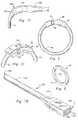
- FIG. 1is a frontal view of a human esophagus, stomach and partial small intestine to illustrate the body locations near the esophagus and small intestine where the inventive medical procedure is performed.
- FIG. 2is a frontal view of a human body cavity showing the esophagus connected to the lower portion of the small intestine and the upper portion of the small intestine, containing the duodenum, being connected to the lower portion of the small intestine.
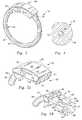
- FIG. 3is an elevated perspective view of the inventive gastric bypass band shown in its engaged state.
- FIG. 4is a cross sectional view through the expansion resistant section of the inventive gastric bypass band.
- FIG. 5Ais a closeup elevated perspective view of the female portion of the latch.
- FIG. 5Bis a closeup elevated perspective view of the male portion of the latch.
- FIG. 5Cis a closeup elevated perspective view of the male portion of the latch fully engaged within the female portion.
- FIG. 6is a side view of the gastric bypass band device shown in an engaged position, illustrating the radial shape of the device.
- FIG. 7Ais a side view of a protective cover for engaging with the female portion of the gastric bypass band device.
- FIG. 7Bis a front elevated perspective view of the cover.
- FIG. 8is an elevated perspective view of the radiopaque marker band of the present invention.
- FIGS. 1 and 2the preferred embodiment of the inventive medical method can be shown.
- the medical methodis performed laparoscopically in 90% of the cases.
- FIG. 1the organs of the esophagus 10 , stomach 14 , duodenum 16 , small intestine 18 and gall bladder 20 are shown.
- the focus of the medical methodis upon the modifications made to the esophagus 10 , stomach 14 and small intestine 18 .
- a gastric pouchis manufactured by preferably separating the esophagus 10 and part of the lesser curvature 22 of the stomach from the remainder of the stomach 14 at point A.
- the small intestine 18is bisected at point B.
- point Bis preferred because it results in the duodenum 16 being completely bypassed along with the stomach 14 . Bypassing the duodenum results in selective fat malabsorption which results in more weight loss than in prior art gastric bypass methods.
- the duodenumremains fully functional and continues to receive liver bile from the hepatic ducts 24 and enzymes from the pancreatic duct 26 .
- the proximal stomachis bisected on the lesser curvature 22 just below the esophagus 10 , leaving a small stomach segment 28 that is connected to the proximal jejunum 18 , this esophogeal and small stomach segment is what will eventually form the gastric pouch 30 having a size of between 20-30 cc.
- the bottom section of the small intestine (proximal jejunum) 18 below the duodenum 16is connected to the small stomach segment 28 through a hand sewn closure to form an anastomosis (not shown) that is 1.5 to 2 cm wide.
- the anastomosisis impervious to air and water and allows direct entry of the contents of the gastric pouch 30 into the small intestine 18 , which causes the release of satiety stimulating chemicals known as enterokinins.
- enterokininssatiety stimulating chemicals known as enterokinins.
- This release of enterokininsis even induced by the obese individual's salivary secretions that go from the gastric pouch 30 to the small intestine 18 .
- This feeling of satiety, or “fullness”results in anorexia and enhances initial weight loss as well as the maintenance of weight loss over time.
- the inventive gastric bypass band device 32Above the anastomosis and above the bottom of the pouch 30 , about 2 cm, is placed the inventive gastric bypass band device 32 .
- the gastric band deviceacts as a restrictor valve which controls the emptying of partially digested food materials from the gastric pouch 30 .
- the gastric band 32is preferably placed at the distal portion of the gastric pouch 30 .
- the portion of the pouch above the gastric bandis 15 to 20 cc in capacity and the portion of the pouch below the band is about 8 to 10 cc in capacity. This compared to the normal 2000-3000 cc capacity of the stomach illustrates the restriction in food intake provided by the gastric pouch.
- the gastric band device 32preferably ranges in size between 5.5-7.0 cm in inner circumference. In addition to its function as a restrictor valve, the gastric band 32 prevents stomal dilation, meaning that the restricted opening provided by the band never expands in size due to the expansion-resistant construction of the device. Moreover, the pouch 30 is more resistant to expansion than the stomach. The relative size of the pouch ensures that excessive expansion does not occur. Patients that have been X-rayed five years post-surgery show that the pouch has not expanded by much.
- the small size of the pouchinsures that if a patient over-eats, the food will back up into the esophagus, thereby causing the patient to regurgitate the food.
- This factoroperates as a self-regulating feature, and for this reason, patients are counseled to keep their food intake to a minimum.
- the duodenum 16is re-joined to the small intestine 18 to form a Y-limb 34 , with one deviation of the limb going upward to the duodenum and the other deviation proceeding upward to the gastric pouch 30 .
- the intestine-intestine connection 36forms an anastomosis (not shown) of approximately 2 cm, that is wide enough to allow food to pass through easily.
- pancreatic juices and liver bile from the duodenumcan now come into contact with the partially digested food that travels down the second section of the intestine from the pouch.
- Liver bilebegins fat digestion for the first time, and as a result, fats are only partially absorbed, thereby helping contribute to weight loss.
- the stomach 14although disconnected, remains fully functional, and if necessary can be reactivated by reversing the surgery and re-connecting the stomach segment 28 and small intestine 18 to their prior, natural, state.
- the stomach 14can also be reactivated by placing a temporary gastrostomy tube 38 , as shown, through which food can be routed, should this be necessary.
- the stomach opening 40can be marked with a radiopaque marker band 42 or disk, that is sutured to the abdominal wall, thereby making it clearly visible to allow the surgeon to find the stomach entry site 40 on an X-ray, to allow easy reactivation.
- the gastric bypass band 32is comprised of an expansion-resistant section 44 mated to a latch 46 , which locks upon full engagement, thereby preventing the device 32 from opening up while positioned within the body.
- the latch 46is of a one-way variety and can only be released through the application of a specialized surgical tool (not shown).
- the expansion-resistant section 44prevents the device from expanding too far, thereby restricting the amount of food traveling from the gastric pouch 30 to the small intestine 18 .
- the expansion-resistant section 44is preferably made from implant grade silicone rubber surrounding a monofilament core.
- the monofilamentcan be polypropylene suture material, which is resistant to expansion.
- the latchis preferably made from surgical-grade plastics such as polypropylene or acetal, which gives both strength and lubricity to the latch.
- FIG. 4shows a transverse cross section of the expansion-resistant section 44 which illustrates the monofilament core 48 surrounded by silicone material 50 .
- the silicone materialcan be a silicone tube having a monofilament core therein.
- the expansion-resistant section 44preferably has a flat-faced inner side 52 as shown. This flat face 52 continues longitudinally along the length of the expansion-resistant section 44 .
- the flat face 52forms a flat-sided inner circumference when the latch of the device is engaged, as shown in FIG. 3 . It has been found that the flat face prevents the expansion-resistant section from migrating into the patient's tissue and prevents tissue erosion.
- the cross-sectional diameter of the expansion-resistant section 44is kept to 0.125′′, or less. If erosion occurs, it has been found that if the cross section is kept to these approximate dimensions the pouch tissue will form a scar around the band device 32 , and in essence seal off the device, thereby preventing any leakage.
- Erosionis caused by tissue necrosis, where tissue dies when the supply of blood to the area is cut off.
- Prior art larger, thicker, band deviceshave been know to necrose when the food pouch begins to sag, making a deep sack out of which food has difficulty being passed. This food begins to decay in the pouch, which can lead to necrotic complications.
- the larger, thicker, prior art devicespenetrate the necrosed area in time, creating a break in the gastric pouch, which can lead to leakage of the pouch contents into the interior of the body cavity. In the worst cases this can lead to death; in the minor cases, additional surgery is necessary to repair the breached pouch. Contrastingly, fewer pouch breaches are experienced with the present invention than with the prior art devices.
- the latch 46can be examined.
- the latchis preferably a one-way latch employing a one-way male-female engagement.
- the opposite ends 54 , 56 of the expansion-resistant section 44are each mated to one-half of the male-female latch as shown in FIG. 3 and a preferred method of mating is further described below.
- the female portion 58 of the latch 46is illustrated in detail.
- the female portionhas an exterior body 60 and an interior lumen 62 for receiving the male portion 64 of the latch.
- the lumen 62is sized to compress the lateral prongs 66 of the male portion 64 .
- a pair of openings 68are placed in each side 70 of the female portion 58 to allow for the expansion of the lateral catches 72 of the male portion 64 .
- the lateral catches 72engage fully and laterally within the side openings 68 , in a one-way fashion.
- Side openings 68have top, bottom, rear and front walls, which engage catches 72 .
- the engagementis such that the latch can be released only after applying a special surgical tool (not shown) to disengage the latch 46 , by placing inward force upon catches 72 through side openings 68 .
- the lumen 62opens outward and the face 74 of the opening of the lumen is inwardly beveled so as to receive the outward bevels 76 of the male portion 64 .
- the corner facings 78 of the female portion 58are rounded so as to present a non-irritating surface to the patient.
- the body 60 of the female portion 58is longitudinally curved 80 .
- the curvature of the female portion 58mates with the longitudinally curved male portion 64 to form the device 32 into a radial shape as shown in FIG. 6 .
- This radial shapeis crucial for preventing the device from becoming ingrown within a patient's tissue, as this shape applies equal pressure to the enclosed tissue at every point along the inside circumference of the device 32 .
- Shapes that are non-circulartend to apply unequal pressure along their inside circumference, thereby resulting in a cutoff of blood supply, necrosis, and eventual tissue erosion and leakage as discussed previously.
- a corresponding radius of curvatureapplies which contributes to the forming of the proper radial shape in each case.
- the inner circumference that is usedis open to the discretion of the surgeon, but generally, men require 6.5 and 7.0 cm sizes while women require 5.5 and 6.0 cm devices.
- the male portion of the latchis shown as comprising a pair of lateral prongs 66 , the prongs being longitudinally curved to mate efficiently within the lumen 62 of the female portion 58 .
- prongs 66are approximately 0.076′′ thick, by 0.040′′ wide.
- the prongsterminate at their front with lateral catches 72 which are molded integrally with the prongs 66 .
- Lateral catches 72are angled longitudinally along their side face 84 , the angled attitude allowing easy entry of the prongs 66 into the lumen 62 of the female portion 58 , which is an important feature under surgical conditions.
- Side faces 84 having steeper anglesgive a mechanical advantage when locking.
- the preferred angle of side facesis 36 degrees or less.
- the catches 72further comprise lateral catch faces 86 , which engage the front walls of the side openings 68 of the female portion 58 . When the catches 72 of prongs engage, it is preferred that they remain engaged under a pulling stress of at least 5 pounds of force.
- the prongs 66are separated by inner space 88 , which allows the prongs to travel inward and outward.
- the prongs 66terminate rearwardly at prong body 90 , which provides a base of structural integrity from which prongs can confidently travel inward and outward as they engage the interior walls of lumen.
- Prong body 90migrates further rearward to become outwardly beveled face 76 which mates with inwardly beveled face 74 of the female portion 58 .
- the beveled face 76migrates further rearward to become hilt 92 .
- Hilt 92is where the front opening of the female portion 58 fully engages against. This engagement is shown in FIG. 5C which illustrates lateral catches 72 seated in the side openings 68 of female portion 58 , the hilt being 92 engaged with the front opening of female portion.
- the circumference of the body 60 of female portion 58 and the circumference of the hilt 92 of the male portion 64are preferably identical so as to provide a fairly uninterrupted surface traveling from one to the other.
- anchor arms 94which are used to attach the male and female portions of latch to the expansion-resistant section 44 .
- Anchor arms 94retain the curved theme of the male and female portions, 58 , 64 of the latch 46 .
- Anchor arms 94are molded integrally with their corresponding latch portion and curve rearwardly so as to retain the radii of curvature of the inventive device noted previously.
- the expansion-resistant sectionwhich is comprised of surgical grade silicone and monofilament is attached to the anchor arms as follows. Referring again to FIG. 5B , the front opening 96 of lumen 98 is shown, and its rearward path of travel through anchor arm is shown in phantom. A similar arrangement exists for female portion.
- Monofilament 48enters the rear of anchor arm and is fed through lumen until it protrudes through the front opening of lumen. The monofilament 48 is then tied off in a manner so as to anchor it in place along with the silicone material as seen in phantom, in FIG. 3 .
- the body 60 of female portion 58may also be fitted with a disposable cover 100 so as to reduce its potential to snag upon tissue as it is being fed through and positioned around the gastric pouch 30 during laparoscopic surgery. As the device is fed through the tissue and around the new pouch, it is led by the female portion 58 .
- Cover 100provides a streamlined shape which can be grasped by a forceps and easily led through the tissue.
- FIG. 7Ais a side view showing the female end 58 positioned in the cover 100 , with the remainder of the device trailing out the back end 102 of cover 100 .
- Back end 102 of coverincludes a lumen (see FIG.
- cover 100further comprises a blunt front end 108 which extends into an elongate portion 110 .
- the blunt front end 108facilitates easy movement through tissue.
- the elongate portion 110is for grasping by the surgeon's forceps to allow the cover to be threaded through tissue.
- the cover 100has a gently tapered region 112 , which, again contributes to easy movement through tissue. At its widest point, the cover is about 0.250 to allow easy movement through a trocar during laparoscopic surgery
- the coveris preferably made from a radiopaque material for easy sighting on an X-ray. The cover is removed and discarded once the device has been positioned around the gastric pouch.
- the radiopaque marker band 42 previously shown in FIG. 2can be more precisely described.
- the band's inside diameteris approximately 0.8′′ and the outside diameter is approximately 1′′ with a thickness of approximately 0.06′′.
- the bandis preferably flat along its major surfaces 114 , 116 .
- the marker band 42can be made from polyester mesh that is coated with surgical grade silicone.
- the inventive device 32can be combined with the radiopaque marker band 42 shown in FIG. 8 , as well as with the disposable cover 100 to form a surgical kit. This kit can then be installed surgically using the method previously described.
Landscapes
- Health & Medical Sciences (AREA)
- Life Sciences & Earth Sciences (AREA)
- Surgery (AREA)
- Engineering & Computer Science (AREA)
- Animal Behavior & Ethology (AREA)
- Veterinary Medicine (AREA)
- Biomedical Technology (AREA)
- Heart & Thoracic Surgery (AREA)
- Public Health (AREA)
- General Health & Medical Sciences (AREA)
- Vascular Medicine (AREA)
- Nuclear Medicine, Radiotherapy & Molecular Imaging (AREA)
- Medical Informatics (AREA)
- Molecular Biology (AREA)
- Obesity (AREA)
- Orthopedic Medicine & Surgery (AREA)
- Nursing (AREA)
- Child & Adolescent Psychology (AREA)
- Oral & Maxillofacial Surgery (AREA)
- Pathology (AREA)
- Reproductive Health (AREA)
- Surgical Instruments (AREA)
- Bag Frames (AREA)
Abstract
Description
Claims (22)
Priority Applications (7)
| Application Number | Priority Date | Filing Date | Title |
|---|---|---|---|
| US10/876,397US7909839B2 (en) | 2004-05-26 | 2004-06-24 | Gastric bypass band and surgical method |
| BRPI0511502-7ABRPI0511502A (en) | 2004-05-26 | 2005-03-16 | Gastric bypass band and surgical method |
| PCT/US2005/008710WO2005117716A2 (en) | 2004-05-26 | 2005-03-16 | Gastric bypass band and surgical method |
| EP05725708.1AEP1778098B1 (en) | 2004-05-26 | 2005-03-16 | Gastric bypass band |
| US13/053,018US8469978B2 (en) | 2004-05-26 | 2011-03-21 | Gastric bypass band and surgical method |
| US13/767,354US20140051914A1 (en) | 2004-05-26 | 2013-02-14 | Gastric bypass band and surgical method |
| US15/170,831US20170020705A1 (en) | 2004-05-26 | 2016-06-01 | Gastric bypass band and surgical method |
Applications Claiming Priority (2)
| Application Number | Priority Date | Filing Date | Title |
|---|---|---|---|
| US57474104P | 2004-05-26 | 2004-05-26 | |
| US10/876,397US7909839B2 (en) | 2004-05-26 | 2004-06-24 | Gastric bypass band and surgical method |
Related Child Applications (1)
| Application Number | Title | Priority Date | Filing Date |
|---|---|---|---|
| US13/053,018ContinuationUS8469978B2 (en) | 2004-05-26 | 2011-03-21 | Gastric bypass band and surgical method |
Publications (2)
| Publication Number | Publication Date |
|---|---|
| US20050277963A1 US20050277963A1 (en) | 2005-12-15 |
| US7909839B2true US7909839B2 (en) | 2011-03-22 |
Family
ID=35461490
Family Applications (4)
| Application Number | Title | Priority Date | Filing Date |
|---|---|---|---|
| US10/876,397Expired - Fee RelatedUS7909839B2 (en) | 2004-05-26 | 2004-06-24 | Gastric bypass band and surgical method |
| US13/053,018Expired - Fee RelatedUS8469978B2 (en) | 2004-05-26 | 2011-03-21 | Gastric bypass band and surgical method |
| US13/767,354AbandonedUS20140051914A1 (en) | 2004-05-26 | 2013-02-14 | Gastric bypass band and surgical method |
| US15/170,831AbandonedUS20170020705A1 (en) | 2004-05-26 | 2016-06-01 | Gastric bypass band and surgical method |
Family Applications After (3)
| Application Number | Title | Priority Date | Filing Date |
|---|---|---|---|
| US13/053,018Expired - Fee RelatedUS8469978B2 (en) | 2004-05-26 | 2011-03-21 | Gastric bypass band and surgical method |
| US13/767,354AbandonedUS20140051914A1 (en) | 2004-05-26 | 2013-02-14 | Gastric bypass band and surgical method |
| US15/170,831AbandonedUS20170020705A1 (en) | 2004-05-26 | 2016-06-01 | Gastric bypass band and surgical method |
Country Status (4)
| Country | Link |
|---|---|
| US (4) | US7909839B2 (en) |
| EP (1) | EP1778098B1 (en) |
| BR (1) | BRPI0511502A (en) |
| WO (1) | WO2005117716A2 (en) |
Cited By (29)
| Publication number | Priority date | Publication date | Assignee | Title |
|---|---|---|---|---|
| US20140051914A1 (en)* | 2004-05-26 | 2014-02-20 | Bariatec Corporation | Gastric bypass band and surgical method |
| US8899979B2 (en)* | 2013-02-28 | 2014-12-02 | Garrison Dental Solutions | Matrix ring for tooth restoration |
| US9011365B2 (en) | 2013-03-12 | 2015-04-21 | Medibotics Llc | Adjustable gastrointestinal bifurcation (AGB) for reduced absorption of unhealthy food |
| US9067070B2 (en) | 2013-03-12 | 2015-06-30 | Medibotics Llc | Dysgeusia-inducing neurostimulation for modifying consumption of a selected nutrient type |
| US9456916B2 (en) | 2013-03-12 | 2016-10-04 | Medibotics Llc | Device for selectively reducing absorption of unhealthy food |
| USD811593S1 (en)* | 2016-02-03 | 2018-02-27 | No-Bull Enterprises, LLC | Ligation device |
| USD822213S1 (en) | 2017-06-13 | 2018-07-03 | Garrison Dental Solutions, Llc | Dental ring |
| US10016220B2 (en) | 2011-11-01 | 2018-07-10 | Nuvasive Specialized Orthopedics, Inc. | Adjustable magnetic devices and methods of using same |
| US10039661B2 (en) | 2006-10-20 | 2018-08-07 | Nuvasive Specialized Orthopedics, Inc. | Adjustable implant and method of use |
| US10045783B2 (en) | 2010-03-12 | 2018-08-14 | No-Bull Enterprises Llc | Method and system for ligating a body part |
| US10238427B2 (en) | 2015-02-19 | 2019-03-26 | Nuvasive Specialized Orthopedics, Inc. | Systems and methods for vertebral adjustment |
| US10271885B2 (en) | 2014-12-26 | 2019-04-30 | Nuvasive Specialized Orthopedics, Inc. | Systems and methods for distraction |
| US10349995B2 (en) | 2007-10-30 | 2019-07-16 | Nuvasive Specialized Orthopedics, Inc. | Skeletal manipulation method |
| US10405891B2 (en) | 2010-08-09 | 2019-09-10 | Nuvasive Specialized Orthopedics, Inc. | Maintenance feature in magnetic implant |
| US10478232B2 (en) | 2009-04-29 | 2019-11-19 | Nuvasive Specialized Orthopedics, Inc. | Interspinous process device and method |
| US10517643B2 (en) | 2009-02-23 | 2019-12-31 | Nuvasive Specialized Orthopedics, Inc. | Non-invasive adjustable distraction system |
| US10617453B2 (en) | 2015-10-16 | 2020-04-14 | Nuvasive Specialized Orthopedics, Inc. | Adjustable devices for treating arthritis of the knee |
| US10646262B2 (en) | 2011-02-14 | 2020-05-12 | Nuvasive Specialized Orthopedics, Inc. | System and method for altering rotational alignment of bone sections |
| US10660675B2 (en) | 2010-06-30 | 2020-05-26 | Nuvasive Specialized Orthopedics, Inc. | External adjustment device for distraction device |
| US10729470B2 (en) | 2008-11-10 | 2020-08-04 | Nuvasive Specialized Orthopedics, Inc. | External adjustment device for distraction device |
| US10743794B2 (en) | 2011-10-04 | 2020-08-18 | Nuvasive Specialized Orthopedics, Inc. | Devices and methods for non-invasive implant length sensing |
| US10751094B2 (en) | 2013-10-10 | 2020-08-25 | Nuvasive Specialized Orthopedics, Inc. | Adjustable spinal implant |
| US10835290B2 (en) | 2015-12-10 | 2020-11-17 | Nuvasive Specialized Orthopedics, Inc. | External adjustment device for distraction device |
| US10918425B2 (en) | 2016-01-28 | 2021-02-16 | Nuvasive Specialized Orthopedics, Inc. | System and methods for bone transport |
| US11191579B2 (en) | 2012-10-29 | 2021-12-07 | Nuvasive Specialized Orthopedics, Inc. | Adjustable devices for treating arthritis of the knee |
| US11202707B2 (en) | 2008-03-25 | 2021-12-21 | Nuvasive Specialized Orthopedics, Inc. | Adjustable implant system |
| USD942028S1 (en)* | 2021-04-19 | 2022-01-25 | Shenzhen Fulinyun Technology Co., Ltd. | Weight reducing apparatus |
| US11246694B2 (en) | 2014-04-28 | 2022-02-15 | Nuvasive Specialized Orthopedics, Inc. | System for informational magnetic feedback in adjustable implants |
| US11357549B2 (en) | 2004-07-02 | 2022-06-14 | Nuvasive Specialized Orthopedics, Inc. | Expandable rod system to treat scoliosis and method of using the same |
Families Citing this family (46)
| Publication number | Priority date | Publication date | Assignee | Title |
|---|---|---|---|---|
| US7211114B2 (en)* | 2002-08-26 | 2007-05-01 | The Trustees Of Columbia University In The City Of New York | Endoscopic gastric bypass |
| US7901419B2 (en)* | 2002-09-04 | 2011-03-08 | Allergan, Inc. | Telemetrically controlled band for regulating functioning of a body organ or duct, and methods of making, implantation and use |
| US7025791B2 (en) | 2002-12-02 | 2006-04-11 | Gi Dynamics, Inc. | Bariatric sleeve |
| US7766973B2 (en) | 2005-01-19 | 2010-08-03 | Gi Dynamics, Inc. | Eversion resistant sleeves |
| US7608114B2 (en) | 2002-12-02 | 2009-10-27 | Gi Dynamics, Inc. | Bariatric sleeve |
| WO2004049982A2 (en) | 2002-12-02 | 2004-06-17 | Gi Dynamics, Inc. | Bariatric sleeve |
| AU2004305450B2 (en) | 2003-12-09 | 2009-01-08 | Gi Dynamics, Inc. | Intestinal sleeve |
| US8057420B2 (en) | 2003-12-09 | 2011-11-15 | Gi Dynamics, Inc. | Gastrointestinal implant with drawstring |
| EP1799145B1 (en) | 2004-09-17 | 2016-12-21 | GI Dynamics, Inc. | Gastrointestinal anchor |
| US7771382B2 (en) | 2005-01-19 | 2010-08-10 | Gi Dynamics, Inc. | Resistive anti-obesity devices |
| US20060244291A1 (en)* | 2005-04-29 | 2006-11-02 | Buell Motorcycle Company | Movable tailrack for a motorcycle |
| US9345604B2 (en)* | 2005-05-02 | 2016-05-24 | Almuhannad Alfrhan | Percutaneous intragastric balloon device and method |
| US7976488B2 (en) | 2005-06-08 | 2011-07-12 | Gi Dynamics, Inc. | Gastrointestinal anchor compliance |
| US7416528B2 (en) | 2005-07-15 | 2008-08-26 | Ethicon Endo-Surgery, Inc. | Latching device for gastric band |
| US8298133B2 (en)* | 2005-07-15 | 2012-10-30 | Ethicon Endo-Surgery, Inc. | Gastric band composed of different hardness materials |
| US8182411B2 (en)* | 2005-07-15 | 2012-05-22 | Ethicon Endo-Surgery, Inc. | Gastric band with mating end profiles |
| US7364542B2 (en)* | 2005-07-15 | 2008-04-29 | Ethicon Endo-Surgery, Inc. | Gastric band suture tab extender |
| US7618365B2 (en)* | 2005-07-15 | 2009-11-17 | Ethicon Endo-Surgery, Inc. | Method of implating a medical device using a suture tab extender |
| US20070015955A1 (en)* | 2005-07-15 | 2007-01-18 | Mark Tsonton | Accordion-like gastric band |
| US7367937B2 (en)* | 2005-07-15 | 2008-05-06 | Ethicon Endo-Surgey, Inc. | Gastric band |
| US7615001B2 (en)* | 2005-07-15 | 2009-11-10 | Ethicon Endo-Surgery, Inc. | Precurved gastric band |
| US7908700B2 (en)* | 2006-02-28 | 2011-03-22 | Dipippo Joe J | Self-cleaning hair brush |
| US20080228126A1 (en)* | 2006-03-23 | 2008-09-18 | The Trustees Of Columbia University In The City Of New York | Method of inhibiting disruption of the healing process in a physically modified stomach |
| US7763039B2 (en)* | 2006-06-09 | 2010-07-27 | Ethicon Endo-Surgery, Inc. | Articulating blunt dissector/gastric band application device |
| US7819836B2 (en) | 2006-06-23 | 2010-10-26 | Gi Dynamics, Inc. | Resistive anti-obesity devices |
| US8246533B2 (en) | 2006-10-20 | 2012-08-21 | Ellipse Technologies, Inc. | Implant system with resonant-driven actuator |
| US8801647B2 (en) | 2007-02-22 | 2014-08-12 | Gi Dynamics, Inc. | Use of a gastrointestinal sleeve to treat bariatric surgery fistulas and leaks |
| US20080255460A1 (en)* | 2007-04-13 | 2008-10-16 | Ethicon Endo-Surgery, Inc. | Nanoparticle tissue based identification and illumination |
| US8034062B2 (en)* | 2007-05-21 | 2011-10-11 | Ethicon Endo-Surgery, Inc. | Methods and devices for placement of an intra-abdominal or intra-thoracic appliance through a natural body orifice |
| FR2929842B1 (en)* | 2008-04-14 | 2011-09-30 | Cie Euro Etude Rech Paroscopie | GASTRIC RING WITH TILT POCKETS |
| JP2011518026A (en)* | 2008-04-22 | 2011-06-23 | エシコン・エンド−サージェリィ・インコーポレイテッド | Method and apparatus for providing direction to a surgical tool |
| FR2941366B1 (en)* | 2009-01-28 | 2011-02-25 | Cie Euro Etude Rech Paroscopie | GASTRIC RING WITH ROD |
| US8702641B2 (en) | 2009-04-03 | 2014-04-22 | Metamodix, Inc. | Gastrointestinal prostheses having partial bypass configurations |
| US9278019B2 (en) | 2009-04-03 | 2016-03-08 | Metamodix, Inc | Anchors and methods for intestinal bypass sleeves |
| US9173760B2 (en) | 2009-04-03 | 2015-11-03 | Metamodix, Inc. | Delivery devices and methods for gastrointestinal implants |
| ES2503553T3 (en) | 2009-04-03 | 2014-10-07 | Metamodix, Inc. | Modular Gastrointestinal Prosthesis |
| AU2010271294B2 (en) | 2009-07-10 | 2015-09-03 | Metamodix, Inc. | External anchoring configurations for modular gastrointestinal prostheses |
| ES2429156T3 (en) | 2010-12-23 | 2013-11-13 | Q Medical International Ag | Medical restriction device for hollow organs of a body |
| WO2014113483A1 (en) | 2013-01-15 | 2014-07-24 | Metamodix, Inc. | System and method for affecting intestinal microbial flora |
| ITMO20130034A1 (en)* | 2013-02-14 | 2014-08-15 | Thd Spa | DEVICE FOR ANAL RIM AND METHOD FOR RESTORING THE SPINTERIAL TONE. |
| FR3011734B1 (en)* | 2013-10-16 | 2015-12-18 | Medical Innovation Dev | GASTRIC BAND OF CALIBRATION |
| WO2016205834A1 (en)* | 2015-06-19 | 2016-12-22 | Mathias Asongwe Lawrence Fobi | Multi-size gastric bypass band and surgical method |
| US9622897B1 (en) | 2016-03-03 | 2017-04-18 | Metamodix, Inc. | Pyloric anchors and methods for intestinal bypass sleeves |
| WO2017201424A1 (en) | 2016-05-19 | 2017-11-23 | Metamodix, Inc. | Pyloric anchor retrieval tools and methods |
| CN109106455B (en)* | 2018-08-15 | 2020-09-04 | 南京市妇幼保健院 | Medical wrist strap and adjustable medical wrist strap lock catch thereof |
| USD998148S1 (en)* | 2021-09-24 | 2023-09-05 | Vivo Surgical Private Limited | Surgical loop |
Citations (14)
| Publication number | Priority date | Publication date | Assignee | Title |
|---|---|---|---|---|
| US3875928A (en)* | 1973-08-16 | 1975-04-08 | Angelchik Jean P | Method for maintaining the reduction of a sliding esophageal hiatal hernia |
| US4592339A (en)* | 1985-06-12 | 1986-06-03 | Mentor Corporation | Gastric banding device |
| US4592355A (en)* | 1983-01-28 | 1986-06-03 | Eliahu Antebi | Process for tying live tissue and an instrument for performing the tying operation |
| US4958791A (en)* | 1986-09-17 | 1990-09-25 | Shinagawa Shoko Co., Ltd. | Tying means |
| WO1994027504A1 (en) | 1993-05-27 | 1994-12-08 | Inamed Development Company | Universal gastric band |
| US5771903A (en) | 1995-09-22 | 1998-06-30 | Kirk Promotions Limited | Surgical method for reducing the food intake of a patient |
| EP1036545A2 (en) | 1999-03-17 | 2000-09-20 | Dudai Moshe | A gastric band |
| US6432040B1 (en) | 2000-09-14 | 2002-08-13 | Nizam N. Meah | Implantable esophageal sphincter apparatus for gastroesophageal reflux disease and method |
| US6572627B2 (en) | 2001-01-08 | 2003-06-03 | Shlomo Gabbay | System to inhibit and/or control expansion of anatomical features |
| WO2003057092A2 (en) | 2002-01-09 | 2003-07-17 | Sofradim Production | Gastric ring for the treatment of obesity |
| US20040267293A1 (en)* | 2003-06-27 | 2004-12-30 | Byrum Randal T. | Implantable band with attachment mechanism |
| US6843253B2 (en)* | 2002-12-11 | 2005-01-18 | C&L Medical Supply Corporation | Urinary-control device |
| US20050075652A1 (en)* | 2003-10-01 | 2005-04-07 | Byrum Randal T. | Gastric band introduction device |
| US20050251181A1 (en)* | 2002-09-04 | 2005-11-10 | Bachmann Michel A | Closure system for surgical ring |
Family Cites Families (4)
| Publication number | Priority date | Publication date | Assignee | Title |
|---|---|---|---|---|
| US3515363A (en)* | 1968-05-06 | 1970-06-02 | Illinois Tool Works | Spring clip |
| US5316543A (en)* | 1990-11-27 | 1994-05-31 | Cook Incorporated | Medical apparatus and methods for treating sliding hiatal hernias |
| FR2825264B1 (en)* | 2001-06-01 | 2004-04-02 | Surgical Diffusion | GASTROPLASTY RING |
| US7909839B2 (en)* | 2004-05-26 | 2011-03-22 | Bariatec Corporation | Gastric bypass band and surgical method |
- 2004
- 2004-06-24USUS10/876,397patent/US7909839B2/ennot_activeExpired - Fee Related
- 2005
- 2005-03-16WOPCT/US2005/008710patent/WO2005117716A2/enactiveApplication Filing
- 2005-03-16EPEP05725708.1Apatent/EP1778098B1/ennot_activeExpired - Lifetime
- 2005-03-16BRBRPI0511502-7Apatent/BRPI0511502A/ennot_activeIP Right Cessation
- 2011
- 2011-03-21USUS13/053,018patent/US8469978B2/ennot_activeExpired - Fee Related
- 2013
- 2013-02-14USUS13/767,354patent/US20140051914A1/ennot_activeAbandoned
- 2016
- 2016-06-01USUS15/170,831patent/US20170020705A1/ennot_activeAbandoned
Patent Citations (17)
| Publication number | Priority date | Publication date | Assignee | Title |
|---|---|---|---|---|
| US3875928A (en)* | 1973-08-16 | 1975-04-08 | Angelchik Jean P | Method for maintaining the reduction of a sliding esophageal hiatal hernia |
| US4592355A (en)* | 1983-01-28 | 1986-06-03 | Eliahu Antebi | Process for tying live tissue and an instrument for performing the tying operation |
| US4592339A (en)* | 1985-06-12 | 1986-06-03 | Mentor Corporation | Gastric banding device |
| US4958791A (en)* | 1986-09-17 | 1990-09-25 | Shinagawa Shoko Co., Ltd. | Tying means |
| WO1994027504A1 (en) | 1993-05-27 | 1994-12-08 | Inamed Development Company | Universal gastric band |
| US5601604A (en) | 1993-05-27 | 1997-02-11 | Inamed Development Co. | Universal gastric band |
| US5771903A (en) | 1995-09-22 | 1998-06-30 | Kirk Promotions Limited | Surgical method for reducing the food intake of a patient |
| US6676674B1 (en) | 1999-03-17 | 2004-01-13 | Moshe Dudai | Gastric band |
| EP1036545A2 (en) | 1999-03-17 | 2000-09-20 | Dudai Moshe | A gastric band |
| US6432040B1 (en) | 2000-09-14 | 2002-08-13 | Nizam N. Meah | Implantable esophageal sphincter apparatus for gastroesophageal reflux disease and method |
| US6572627B2 (en) | 2001-01-08 | 2003-06-03 | Shlomo Gabbay | System to inhibit and/or control expansion of anatomical features |
| WO2003057092A2 (en) | 2002-01-09 | 2003-07-17 | Sofradim Production | Gastric ring for the treatment of obesity |
| US20050038458A1 (en)* | 2002-01-09 | 2005-02-17 | Pierre Bailly | Gastric ring for treatment of obesity |
| US20050251181A1 (en)* | 2002-09-04 | 2005-11-10 | Bachmann Michel A | Closure system for surgical ring |
| US6843253B2 (en)* | 2002-12-11 | 2005-01-18 | C&L Medical Supply Corporation | Urinary-control device |
| US20040267293A1 (en)* | 2003-06-27 | 2004-12-30 | Byrum Randal T. | Implantable band with attachment mechanism |
| US20050075652A1 (en)* | 2003-10-01 | 2005-04-07 | Byrum Randal T. | Gastric band introduction device |
Non-Patent Citations (9)
| Title |
|---|
| EM Pro-Ring Advertisement and Website. |
| Heliogast Advertisement and Website. |
| Inamed Lap Band Advertisement and Website. |
| Mathias A.L. Fobi, MD, FACS "Placement of the GaBP Ring System in the Banded Gastric Bypass Operation," Obesity Surgery, vol. 15, 1196-1201 (2005) USA (see p. 1197). |
| Mathias A.L. Fobi, MD, FACS et al., "Band Erosion: Incidence, Etiology, Management and Outcome after Banded Vertical Gastric Bypass," Obesity Surgery, vol. 11, pp. 1-9 (2001) USA (see Fig. 10, Fig. 5; pp. 1, 5, and 7). |
| Midband Advertisement. |
| Search Report for PCT/US20050008710, Nov. 6, 2009. |
| Siliband Website. |
| Swedish Adjustable Gastric Band Advertisement. |
Cited By (40)
| Publication number | Priority date | Publication date | Assignee | Title |
|---|---|---|---|---|
| US20140051914A1 (en)* | 2004-05-26 | 2014-02-20 | Bariatec Corporation | Gastric bypass band and surgical method |
| US11357549B2 (en) | 2004-07-02 | 2022-06-14 | Nuvasive Specialized Orthopedics, Inc. | Expandable rod system to treat scoliosis and method of using the same |
| US10039661B2 (en) | 2006-10-20 | 2018-08-07 | Nuvasive Specialized Orthopedics, Inc. | Adjustable implant and method of use |
| US11672684B2 (en) | 2006-10-20 | 2023-06-13 | Nuvasive Specialized Orthopedics, Inc. | Adjustable implant and method of use |
| US11234849B2 (en) | 2006-10-20 | 2022-02-01 | Nuvasive Specialized Orthopedics, Inc. | Adjustable implant and method of use |
| US11172972B2 (en) | 2007-10-30 | 2021-11-16 | Nuvasive Specialized Orthopedics, Inc. | Skeletal manipulation method |
| US10349995B2 (en) | 2007-10-30 | 2019-07-16 | Nuvasive Specialized Orthopedics, Inc. | Skeletal manipulation method |
| US11202707B2 (en) | 2008-03-25 | 2021-12-21 | Nuvasive Specialized Orthopedics, Inc. | Adjustable implant system |
| US10729470B2 (en) | 2008-11-10 | 2020-08-04 | Nuvasive Specialized Orthopedics, Inc. | External adjustment device for distraction device |
| US10517643B2 (en) | 2009-02-23 | 2019-12-31 | Nuvasive Specialized Orthopedics, Inc. | Non-invasive adjustable distraction system |
| US10478232B2 (en) | 2009-04-29 | 2019-11-19 | Nuvasive Specialized Orthopedics, Inc. | Interspinous process device and method |
| US10045783B2 (en) | 2010-03-12 | 2018-08-14 | No-Bull Enterprises Llc | Method and system for ligating a body part |
| US11844525B2 (en) | 2010-03-12 | 2023-12-19 | No-Bull Enterprises Llc | Method and system for ligating a body part |
| US10772634B2 (en) | 2010-03-12 | 2020-09-15 | No-Bull Enterprises Llc | Method and system for ligating a body part |
| US10660675B2 (en) | 2010-06-30 | 2020-05-26 | Nuvasive Specialized Orthopedics, Inc. | External adjustment device for distraction device |
| US10405891B2 (en) | 2010-08-09 | 2019-09-10 | Nuvasive Specialized Orthopedics, Inc. | Maintenance feature in magnetic implant |
| US10646262B2 (en) | 2011-02-14 | 2020-05-12 | Nuvasive Specialized Orthopedics, Inc. | System and method for altering rotational alignment of bone sections |
| US10743794B2 (en) | 2011-10-04 | 2020-08-18 | Nuvasive Specialized Orthopedics, Inc. | Devices and methods for non-invasive implant length sensing |
| US11123107B2 (en) | 2011-11-01 | 2021-09-21 | Nuvasive Specialized Orthopedics, Inc. | Adjustable magnetic devices and methods of using same |
| US10349982B2 (en) | 2011-11-01 | 2019-07-16 | Nuvasive Specialized Orthopedics, Inc. | Adjustable magnetic devices and methods of using same |
| US10016220B2 (en) | 2011-11-01 | 2018-07-10 | Nuvasive Specialized Orthopedics, Inc. | Adjustable magnetic devices and methods of using same |
| US11213330B2 (en) | 2012-10-29 | 2022-01-04 | Nuvasive Specialized Orthopedics, Inc. | Adjustable devices for treating arthritis of the knee |
| US11191579B2 (en) | 2012-10-29 | 2021-12-07 | Nuvasive Specialized Orthopedics, Inc. | Adjustable devices for treating arthritis of the knee |
| US8899979B2 (en)* | 2013-02-28 | 2014-12-02 | Garrison Dental Solutions | Matrix ring for tooth restoration |
| US9456916B2 (en) | 2013-03-12 | 2016-10-04 | Medibotics Llc | Device for selectively reducing absorption of unhealthy food |
| US9011365B2 (en) | 2013-03-12 | 2015-04-21 | Medibotics Llc | Adjustable gastrointestinal bifurcation (AGB) for reduced absorption of unhealthy food |
| US9067070B2 (en) | 2013-03-12 | 2015-06-30 | Medibotics Llc | Dysgeusia-inducing neurostimulation for modifying consumption of a selected nutrient type |
| US10751094B2 (en) | 2013-10-10 | 2020-08-25 | Nuvasive Specialized Orthopedics, Inc. | Adjustable spinal implant |
| US11246694B2 (en) | 2014-04-28 | 2022-02-15 | Nuvasive Specialized Orthopedics, Inc. | System for informational magnetic feedback in adjustable implants |
| US10271885B2 (en) | 2014-12-26 | 2019-04-30 | Nuvasive Specialized Orthopedics, Inc. | Systems and methods for distraction |
| US11439449B2 (en) | 2014-12-26 | 2022-09-13 | Nuvasive Specialized Orthopedics, Inc. | Systems and methods for distraction |
| US10238427B2 (en) | 2015-02-19 | 2019-03-26 | Nuvasive Specialized Orthopedics, Inc. | Systems and methods for vertebral adjustment |
| US11612416B2 (en) | 2015-02-19 | 2023-03-28 | Nuvasive Specialized Orthopedics, Inc. | Systems and methods for vertebral adjustment |
| US12076051B2 (en) | 2015-02-19 | 2024-09-03 | Nuvasive Specialized Orthopedics, Inc. | Systems and methods for vertebral adjustment |
| US10617453B2 (en) | 2015-10-16 | 2020-04-14 | Nuvasive Specialized Orthopedics, Inc. | Adjustable devices for treating arthritis of the knee |
| US10835290B2 (en) | 2015-12-10 | 2020-11-17 | Nuvasive Specialized Orthopedics, Inc. | External adjustment device for distraction device |
| US10918425B2 (en) | 2016-01-28 | 2021-02-16 | Nuvasive Specialized Orthopedics, Inc. | System and methods for bone transport |
| USD811593S1 (en)* | 2016-02-03 | 2018-02-27 | No-Bull Enterprises, LLC | Ligation device |
| USD822213S1 (en) | 2017-06-13 | 2018-07-03 | Garrison Dental Solutions, Llc | Dental ring |
| USD942028S1 (en)* | 2021-04-19 | 2022-01-25 | Shenzhen Fulinyun Technology Co., Ltd. | Weight reducing apparatus |
Also Published As
| Publication number | Publication date |
|---|---|
| US20110208216A1 (en) | 2011-08-25 |
| EP1778098B1 (en) | 2014-10-29 |
| EP1778098A2 (en) | 2007-05-02 |
| US20170020705A1 (en) | 2017-01-26 |
| US20050277963A1 (en) | 2005-12-15 |
| US20140051914A1 (en) | 2014-02-20 |
| US8469978B2 (en) | 2013-06-25 |
| WO2005117716A3 (en) | 2006-11-16 |
| EP1778098A4 (en) | 2009-12-09 |
| WO2005117716A2 (en) | 2005-12-15 |
| BRPI0511502A (en) | 2008-01-08 |
Similar Documents
| Publication | Publication Date | Title |
|---|---|---|
| US7909839B2 (en) | Gastric bypass band and surgical method | |
| US7037344B2 (en) | Apparatus and methods for treatment of morbid obesity | |
| AU2006203007B2 (en) | Latching device for gastric band | |
| EP1992313B1 (en) | Gastric band with engagement member | |
| US9839546B2 (en) | Apparatus and methods for treatment of morbid obesity | |
| US8506516B2 (en) | Devices, systems, and methods for achieving magnetic gastric bypass | |
| US20080249533A1 (en) | Medical Device and Method For Controlling Obesity | |
| US8167896B2 (en) | Devices, systems, and methods for organ restriction | |
| US9730822B2 (en) | Gastrointestinal device | |
| US20080221597A1 (en) | Methods and devices for intragastrointestinal fixation | |
| JP2008541854A (en) | Restricted and / or occluded implant system for promoting weight loss | |
| US8790290B2 (en) | Gastric restrictor assembly and method of use | |
| US20250057678A1 (en) | Methods and devices for gastricintestinal tract bypass | |
| WO2013026473A1 (en) | Devices and methods for anchoring an endoluminal sleeve in the gi tract | |
| MXPA06008070A (en) | Method of implating a medical device using a suture tab extender |
Legal Events
| Date | Code | Title | Description |
|---|---|---|---|
| AS | Assignment | Owner name:BENTEC MEDICAL, INC., CALIFORNIA Free format text:ASSIGNMENT OF ASSIGNORS INTEREST;ASSIGNOR:FIELDS, C. BRUCE;REEL/FRAME:016338/0982 Effective date:20040621 | |
| AS | Assignment | Owner name:BARIATEC CORPORATION, CALIFORNIA Free format text:ASSIGNMENT OF ASSIGNORS INTEREST;ASSIGNOR:BENTEC MEDICAL, INC.;REEL/FRAME:023289/0863 Effective date:20090715 | |
| STCF | Information on status: patent grant | Free format text:PATENTED CASE | |
| AS | Assignment | Owner name:BARIATEC CORPORATION, CALIFORNIA Free format text:ASSIGNMENT OF ASSIGNORS INTEREST;ASSIGNOR:FOBI, MATHIAS ASONGWE LAWRENCE;REEL/FRAME:025982/0848 Effective date:20110318 | |
| AS | Assignment | Owner name:BARIATEC CORPORATION, CALIFORNIA Free format text:ASSIGNMENT OF ASSIGNORS INTEREST;ASSIGNOR:BENTEC MEDICAL, INC.;REEL/FRAME:026021/0475 Effective date:20090715 Owner name:BENTEC MEDICAL, INC., CALIFORNIA Free format text:ASSIGNMENT OF ASSIGNORS INTEREST;ASSIGNOR:FIELDS, C. BRUCE;REEL/FRAME:026021/0362 Effective date:20040621 Owner name:BARIATEC CORPORATION, CALIFORNIA Free format text:ASSIGNMENT OF ASSIGNORS INTEREST;ASSIGNOR:FOBI, MATHIAS ASONGWE LAWRENCE;REEL/FRAME:026021/0498 Effective date:20110318 | |
| FPAY | Fee payment | Year of fee payment:4 | |
| FEPP | Fee payment procedure | Free format text:MAINTENANCE FEE REMINDER MAILED (ORIGINAL EVENT CODE: REM.); ENTITY STATUS OF PATENT OWNER: SMALL ENTITY | |
| LAPS | Lapse for failure to pay maintenance fees | Free format text:PATENT EXPIRED FOR FAILURE TO PAY MAINTENANCE FEES (ORIGINAL EVENT CODE: EXP.); ENTITY STATUS OF PATENT OWNER: SMALL ENTITY | |
| STCH | Information on status: patent discontinuation | Free format text:PATENT EXPIRED DUE TO NONPAYMENT OF MAINTENANCE FEES UNDER 37 CFR 1.362 | |
| FP | Expired due to failure to pay maintenance fee | Effective date:20190322 |