US7909830B2 - Methods of spinal fixation and instrumentation - Google Patents
Methods of spinal fixation and instrumentationDownload PDFInfo
- Publication number
- US7909830B2 US7909830B2US11/213,041US21304105AUS7909830B2US 7909830 B2US7909830 B2US 7909830B2US 21304105 AUS21304105 AUS 21304105AUS 7909830 B2US7909830 B2US 7909830B2
- Authority
- US
- United States
- Prior art keywords
- longitudinal
- guide
- sleeve
- opening
- distal end
- Prior art date
- Legal status (The legal status is an assumption and is not a legal conclusion. Google has not performed a legal analysis and makes no representation as to the accuracy of the status listed.)
- Active, expires
Links
- 238000000034methodMethods0.000titleabstractdescription54
- 238000003780insertionMethods0.000claimsabstractdescription236
- 230000037431insertionEffects0.000claimsabstractdescription236
- 230000007246mechanismEffects0.000claimsdescription47
- 239000007943implantSubstances0.000claimsdescription27
- 230000003387muscularEffects0.000claims1
- 210000001519tissueAnatomy0.000description24
- 239000000463materialSubstances0.000description22
- 238000010276constructionMethods0.000description17
- 238000001356surgical procedureMethods0.000description16
- 210000003205muscleAnatomy0.000description14
- 238000004140cleaningMethods0.000description11
- 239000004696Poly ether ether ketoneSubstances0.000description8
- 239000002131composite materialSubstances0.000description8
- 229910052751metalInorganic materials0.000description8
- 239000002184metalSubstances0.000description8
- 229920002530polyetherether ketonePolymers0.000description8
- 230000001954sterilising effectEffects0.000description8
- 238000004659sterilization and disinfectionMethods0.000description8
- RTAQQCXQSZGOHL-UHFFFAOYSA-NTitaniumChemical compound[Ti]RTAQQCXQSZGOHL-UHFFFAOYSA-N0.000description7
- 238000013459approachMethods0.000description7
- 239000010936titaniumSubstances0.000description7
- 229910052719titaniumInorganic materials0.000description7
- 210000000988bone and boneAnatomy0.000description6
- 210000003811fingerAnatomy0.000description6
- 239000010935stainless steelSubstances0.000description6
- 229910001220stainless steelInorganic materials0.000description6
- 210000003484anatomyAnatomy0.000description5
- 229920000049Carbon (fiber)Polymers0.000description4
- 239000004698PolyethyleneSubstances0.000description4
- 239000004809TeflonSubstances0.000description4
- 229920006362Teflon®Polymers0.000description4
- 229920010741Ultra High Molecular Weight Polyethylene (UHMWPE)Polymers0.000description4
- 229910045601alloyInorganic materials0.000description4
- 239000000956alloySubstances0.000description4
- 229910052782aluminiumInorganic materials0.000description4
- XAGFODPZIPBFFR-UHFFFAOYSA-NaluminiumChemical compound[Al]XAGFODPZIPBFFR-UHFFFAOYSA-N0.000description4
- 239000008280bloodSubstances0.000description4
- 210000004369bloodAnatomy0.000description4
- 239000004917carbon fiberSubstances0.000description4
- 239000000919ceramicSubstances0.000description4
- 230000010339dilationEffects0.000description4
- 229920001971elastomerPolymers0.000description4
- 239000004816latexSubstances0.000description4
- 229920000126latexPolymers0.000description4
- VNWKTOKETHGBQD-UHFFFAOYSA-NmethaneChemical compoundCVNWKTOKETHGBQD-UHFFFAOYSA-N0.000description4
- 229920003023plasticPolymers0.000description4
- 239000004033plasticSubstances0.000description4
- 239000004417polycarbonateSubstances0.000description4
- 229920000515polycarbonatePolymers0.000description4
- 229920000728polyesterPolymers0.000description4
- -1polyethylenePolymers0.000description4
- 229920000573polyethylenePolymers0.000description4
- 229920000642polymerPolymers0.000description4
- 239000004800polyvinyl chlorideSubstances0.000description4
- 239000005060rubberSubstances0.000description4
- 238000010186stainingMethods0.000description4
- 239000000126substanceSubstances0.000description4
- 238000005266castingMethods0.000description3
- 238000000748compression mouldingMethods0.000description3
- 238000001125extrusionMethods0.000description3
- 238000005242forgingMethods0.000description3
- 238000001746injection mouldingMethods0.000description3
- 238000003754machiningMethods0.000description3
- 238000012986modificationMethods0.000description3
- 230000004048modificationEffects0.000description3
- 239000000523sampleSubstances0.000description3
- 238000001721transfer mouldingMethods0.000description3
- 230000000712assemblyEffects0.000description2
- 238000000429assemblyMethods0.000description2
- 239000011248coating agentSubstances0.000description2
- 238000000576coating methodMethods0.000description2
- 230000004313glareEffects0.000description2
- 238000007373indentationMethods0.000description2
- 208000014674injuryDiseases0.000description2
- 239000007779soft materialSubstances0.000description2
- 239000007787solidSubstances0.000description2
- 238000006467substitution reactionMethods0.000description2
- 230000008733traumaEffects0.000description2
- 206010061310Nerve root injuryDiseases0.000description1
- 208000004550Postoperative PainDiseases0.000description1
- 206010058907Spinal deformityDiseases0.000description1
- 229910000831SteelInorganic materials0.000description1
- 238000007792additionMethods0.000description1
- 238000003776cleavage reactionMethods0.000description1
- 230000000295complement effectEffects0.000description1
- 230000006835compressionEffects0.000description1
- 238000007906compressionMethods0.000description1
- 230000007850degenerationEffects0.000description1
- 230000000916dilatatory effectEffects0.000description1
- 210000003195fasciaAnatomy0.000description1
- 239000000835fiberSubstances0.000description1
- 239000012530fluidSubstances0.000description1
- 210000004247handAnatomy0.000description1
- 238000002513implantationMethods0.000description1
- 238000003973irrigationMethods0.000description1
- 238000002559palpationMethods0.000description1
- 230000002980postoperative effectEffects0.000description1
- 230000002035prolonged effectEffects0.000description1
- 238000011084recoveryMethods0.000description1
- 238000002271resectionMethods0.000description1
- 238000010079rubber tappingMethods0.000description1
- 230000007017scissionEffects0.000description1
- 238000000926separation methodMethods0.000description1
- 210000004872soft tissueAnatomy0.000description1
- 230000006641stabilisationEffects0.000description1
- 238000011105stabilizationMethods0.000description1
- 239000010959steelSubstances0.000description1
- 210000003813thumbAnatomy0.000description1
- 238000012800visualizationMethods0.000description1
- 238000003466weldingMethods0.000description1
- 210000002517zygapophyseal jointAnatomy0.000description1
Images


Classifications
- A—HUMAN NECESSITIES
- A61—MEDICAL OR VETERINARY SCIENCE; HYGIENE
- A61B—DIAGNOSIS; SURGERY; IDENTIFICATION
- A61B17/00—Surgical instruments, devices or methods
- A61B17/56—Surgical instruments or methods for treatment of bones or joints; Devices specially adapted therefor
- A61B17/58—Surgical instruments or methods for treatment of bones or joints; Devices specially adapted therefor for osteosynthesis, e.g. bone plates, screws or setting implements
- A61B17/68—Internal fixation devices, including fasteners and spinal fixators, even if a part thereof projects from the skin
- A61B17/70—Spinal positioners or stabilisers, e.g. stabilisers comprising fluid filler in an implant
- A61B17/7001—Screws or hooks combined with longitudinal elements which do not contact vertebrae
- A61B17/7002—Longitudinal elements, e.g. rods
- A—HUMAN NECESSITIES
- A61—MEDICAL OR VETERINARY SCIENCE; HYGIENE
- A61B—DIAGNOSIS; SURGERY; IDENTIFICATION
- A61B17/00—Surgical instruments, devices or methods
- A61B17/56—Surgical instruments or methods for treatment of bones or joints; Devices specially adapted therefor
- A61B17/58—Surgical instruments or methods for treatment of bones or joints; Devices specially adapted therefor for osteosynthesis, e.g. bone plates, screws or setting implements
- A—HUMAN NECESSITIES
- A61—MEDICAL OR VETERINARY SCIENCE; HYGIENE
- A61B—DIAGNOSIS; SURGERY; IDENTIFICATION
- A61B17/00—Surgical instruments, devices or methods
- A61B17/56—Surgical instruments or methods for treatment of bones or joints; Devices specially adapted therefor
- A—HUMAN NECESSITIES
- A61—MEDICAL OR VETERINARY SCIENCE; HYGIENE
- A61B—DIAGNOSIS; SURGERY; IDENTIFICATION
- A61B17/00—Surgical instruments, devices or methods
- A61B17/56—Surgical instruments or methods for treatment of bones or joints; Devices specially adapted therefor
- A61B17/58—Surgical instruments or methods for treatment of bones or joints; Devices specially adapted therefor for osteosynthesis, e.g. bone plates, screws or setting implements
- A61B17/68—Internal fixation devices, including fasteners and spinal fixators, even if a part thereof projects from the skin
- A61B17/70—Spinal positioners or stabilisers, e.g. stabilisers comprising fluid filler in an implant
- A61B17/7074—Tools specially adapted for spinal fixation operations other than for bone removal or filler handling
- A61B17/7083—Tools for guidance or insertion of tethers, rod-to-anchor connectors, rod-to-rod connectors, or longitudinal elements
- A61B17/7085—Tools for guidance or insertion of tethers, rod-to-anchor connectors, rod-to-rod connectors, or longitudinal elements for insertion of a longitudinal element down one or more hollow screw or hook extensions, i.e. at least a part of the element within an extension has a component of movement parallel to the extension's axis
- A—HUMAN NECESSITIES
- A61—MEDICAL OR VETERINARY SCIENCE; HYGIENE
- A61B—DIAGNOSIS; SURGERY; IDENTIFICATION
- A61B17/00—Surgical instruments, devices or methods
- A61B17/56—Surgical instruments or methods for treatment of bones or joints; Devices specially adapted therefor
- A61B17/58—Surgical instruments or methods for treatment of bones or joints; Devices specially adapted therefor for osteosynthesis, e.g. bone plates, screws or setting implements
- A61B17/68—Internal fixation devices, including fasteners and spinal fixators, even if a part thereof projects from the skin
- A61B17/70—Spinal positioners or stabilisers, e.g. stabilisers comprising fluid filler in an implant
- A61B17/7001—Screws or hooks combined with longitudinal elements which do not contact vertebrae
- A61B17/7002—Longitudinal elements, e.g. rods
- A61B17/7011—Longitudinal element being non-straight, e.g. curved, angled or branched
- A—HUMAN NECESSITIES
- A61—MEDICAL OR VETERINARY SCIENCE; HYGIENE
- A61B—DIAGNOSIS; SURGERY; IDENTIFICATION
- A61B17/00—Surgical instruments, devices or methods
- A61B17/56—Surgical instruments or methods for treatment of bones or joints; Devices specially adapted therefor
- A61B17/58—Surgical instruments or methods for treatment of bones or joints; Devices specially adapted therefor for osteosynthesis, e.g. bone plates, screws or setting implements
- A61B17/68—Internal fixation devices, including fasteners and spinal fixators, even if a part thereof projects from the skin
- A61B17/70—Spinal positioners or stabilisers, e.g. stabilisers comprising fluid filler in an implant
- A61B17/7001—Screws or hooks combined with longitudinal elements which do not contact vertebrae
- A61B17/7035—Screws or hooks, wherein a rod-clamping part and a bone-anchoring part can pivot relative to each other
- A61B17/7037—Screws or hooks, wherein a rod-clamping part and a bone-anchoring part can pivot relative to each other wherein pivoting is blocked when the rod is clamped
Definitions
- the present inventionis directed to methods of spinal fixation and, in particular, surgical instruments for performing a minimally invasive spinal fixation procedure.
- Spinal fixation systemswhich are used to correct spinal deformities and treat spinal degenerations generally consist of a series of bone fasteners anchored in, for example, the pedicle of adjacent vertebra.
- the bone fastenersare interconnected to one another by one or more elongated spinal rods or plates.
- open approach surgical techniqueshave traditionally been employed. These open procedures generally involve large skin incisions and extensive tissue retraction and resection, all which may result in considerable post-operative pain and prolonged recovery time.
- a paraspinal approachis one form of minimally invasive technique and involves muscle splitting or muscle sparing in order to gain access to the posterior elements of the spine. Such a technique minimizes trauma to tissues adjacent the spine.
- the paraspinal approachinvolves separation or splitting of the muscles along their fibers.
- a midline skin incisionis made and followed by bi/unilateral fascia incision. The muscles are then separated to allow access to the spine via a single skin incision. Additionally, one or more off-midline skin incisions may be made to allow for a more direct approach.
- Implanting a spinal rod fixation systemgenerally involves at least two steps: (i) placing implants (e.g., screws) into the spine and (ii) inserting a rod between the implants.
- implantse.g., screws
- the starting insertion point, the trajectory of the implants and the implants' sizeare important to proper implant placement.
- the spinal implantgenerally comprises a screw portion and a body portion. The screw portion is inserted into the spine and the body portion generally has a channel into which a spinal rod is inserted and secured.
- the procedure to insert the rodmay require insertion of the rod through an incision in the skin, which may be separate and distinct from the incision through which the implant(s) is placed. In other procedures, the rod is inserted through the same incision as the implant(s).
- the present inventionrelates to a method of performing a fixation procedure and the instrumentation used to perform the procedure.
- a radiographic imagemay be taken of the spine, including the vertebrae which are to receive implants. From the radiographic image, one or more insertion points may be located on a patient's back.
- a surgeonmay make one or more incisions in a patient's back to form one or more openings. Thereafter, a surgeon may form a passageway through the incision(s) from the skin to the spine (e.g., by dilation or palpation).
- An entire proceduremay be performed through a single incision or a procedure may be performed using multiple incisions.
- a screwmay be inserted through the incision.
- the screwmay have a shaft, which may be inserted into bone, and a head portion operably connected to the shaft, preferably so the head portion can move relative to the screw shaft and preferably polyaxially rotate relative to the screw shaft.
- a drill, awl, probe and/or screwdrivermay be used to insert the screw into a vertebrae.
- An insertion guidemay be attached to the screw and, in particular, the head portion of the screw before or after the screw has been inserted into the body.
- the insertion guidemay have a first and second section which may be connected to each other to form a tube having a bore therethrough.
- the first sectionmay have a distal end, a proximal end, a first longitudinal slot extending from the distal end towards the proximal end, and at least one protrusion.
- the second sectionmay have a distal end, a proximal end, a second longitudinal slot extending from the distal end towards the proximal end, and at least one recess for receiving the at least one protrusion.
- the second longitudinal slotmay be diametrically opposed to the first longitudinal slot.
- the distal ends of the first and second sectionsmay be sized and configured to engage the head portion of a screw.
- the distal end of at least one of the first and second sectionsmay have a flange and at least one retaining portion extending from the flange into the bore.
- the flangemay be sized and configured to be inserted into a groove in the head portion of the screw to prevent the screw and the insertion guide from being separated from each other.
- the at least one retaining portionmay be sized and configured to engage at least one surface of the head portion of the screw to prevent rotation of the insertion guide with respect to the screw.
- at least one of the first and second sectionsmay have a ring member which may provide a gripping surface for a surgeon to connect and/or disconnect the first and second sections.
- the insertion guidemay have an elongated body with a distal end, a proximal end, and a bore extending from the distal end to the proximal end.
- the bodymay have first and second longitudinal slots which may extend from the distal end towards the proximal end of the insertion guide.
- the first and second longitudinal slotsmay be diametrically opposed to each other.
- At least one slotmay be positioned between the first and second longitudinal slots.
- Such a constructionmay form a plurality of arms.
- the armsmay engage the head portion of the screw.
- the plurality of armsmay have a flange and at least one retaining portion extending from the flange into the bore.
- the flangemay be sized and configured to be inserted into a groove in the head portion of the screw to prevent the screw and insertion guide from being separated from each other.
- the at least one retaining portionmay be sized and configured to engage at least one surface of the head portion of the screw to prevent rotation of the insertion guide with respect to the screw.
- the insertion guidemay have an inner sleeve and an outer sleeve.
- the inner sleevemay comprise a distal end, a proximal end, a bore extending from the distal end to the proximal end, a body, first and second arms extending from the body, first and second longitudinal slots positioned between the arms, and an actuating mechanism positioned along the body.
- the outer sleevemay comprise a distal end, a proximal end and an engagement member.
- the outer sleevemay have a first position where the proximal end of the outer sleeve may be positioned a first distance from the proximal end of the inner sleeve and a second position where the proximal end of the outer sleeve may be positioned a second distance from the proximal end of the inner sleeve, wherein the second distance is greater than the first distance.
- the outer sleevemay be positioned over the inner sleeve so that the engagement member of the outer sleeve may engage the actuating mechanism of the inner sleeve for moving the outer sleeve between the first and second position.
- One method of attaching an insertion guide to a screwmay comprise providing a screw having a shaft and a head portion, wherein the head portion may have a channel therethrough, providing a holder comprising a body, an opening through the body for receiving the screw, a ledge and counterbore proximate the opening, and a fixing member, positioning the shaft of the screw through the opening so that the head portion is positioned against the ledge, moving the fixing member between a first position where the fixing member is not positioned within the channel of the head portion and a second position where at least a portion of the fixing member is positioned within the channel of the head portion, providing an insertion guide having a proximal end and a distal end, inserting the distal end of the insertion guide into the counterbore, and engaging the distal end of the insertion guide with the head portion of the screw.
- the process of inserting a screw into a vertebrae and attaching an insertion guide to the screwmay be repeated through additional, separate incisions.
- a sleevemay be inserted through an outermost insertion guide (e.g., the insertion guide attached to a vertebrae at the end of the group of vertebrae to be connected).
- the sleevemay be an elongated body with a distal end, a proximal end, and a passageway extending from the distal end to the proximal end.
- the sleevemay have a first longitudinal opening which may extend a first distance from the distal end towards the proximal end and a second longitudinal opening diametrically opposed to the first longitudinal opening which may extend a second distance from the distal end towards the proximal end. The second distance may be less than the first distance.
- the sleevemay also have a first opening which may intersect the first longitudinal opening at an angle and a second opening which may intersect the second longitudinal opening at an angle. In one embodiment, the first opening may intersect the first longitudinal opening at a substantially perpendicular angle and the second opening may intersect the second longitudinal opening at a substantially perpendicular angle.
- the sleevemay be used to guide the movement of a rod through the insertion guides and tissue.
- a rodmay be inserted through the sleeve, through tissue and into the head portions of screws.
- a surgeonmay grab an end of the rod and insert it with his/her hand/fingers.
- a holding instrumentmay be attached to the rod and may be used to insert the rod into the body.
- the rodmay have an axis, a distal end, a proximal end, and a receiving portion at the proximal end.
- the holding instrumentmay have an axis and may comprise an outer member and an inner member.
- the outer membermay have a distal end, a proximal end, a pair of flexible arms proximate the distal end, and a passageway extending from the proximal end to the distal end.
- the pair of armsmay be positionable within the receiving portion of the rod.
- the inner membermay have a distal end, a proximal end, and a tip at the proximal end.
- the inner membermay be sized and configured for insertion through the passageway of the outer member so that the distal end of the inner member may be inserted between the pair of arms. When the distal end of the inner member is inserted between the pair of arms, the arms may each move outward and engage the receiving portion of the rod.
- the receiving portion of the rodmay have at least one recess and the tip of the inner member may be positionable within that at least one recess.
- an operatormay fix the orientation of the holding instrument relative to the rod.
- the axis of the rodmay be aligned with the axis of the holding instrument and, in another orientation, the axis of the rod may be at an angle with respect to the holding instrument.
- the outer membermay have a threaded portion inside the passageway for engaging corresponding threads on the inner member such that rotation of the inner member relative to the outer member may results in the inner member moving into and out of the passageway of the outer member.
- the receiving portionmay also have one or more, preferably at least two or more bores or grooves.
- Each bore or groovemay receive an arm of the outer member such that the rod may be rotated with respect to the holding instrument.
- the armsWhen the distal portion of the inner member is inserted in between the arms, the arms may flex outwards and may engage the bores or grooves to hold the rod relative to the holding instrument.
- each armmay have a hemispherical shaped portion and the grooves may be hemispherical in shape to receive the hemispherical shaped portion of the arms.
- the rodmay have an axis, a distal end, a proximal end, and an engagement portion at the proximal end.
- the holding instrumentmay have an axis and may include an outer sleeve and an inner sleeve.
- the outer sleevemay have a distal end, a proximal end and a passageway therethrough.
- the inner sleevemay have a distal end and a proximal end, and may be positioned within the passageway of the outer sleeve.
- the inner sleevemay have a portion at the distal end for engaging the engagement portion of the elongated rod.
- the distal end of the outer sleevemay be selectively moveable over the distal end of the inner sleeve to fix the holding instrument with respect to the rod.
- the engagement portion of the elongated rodmay be spherical in shape and the inner sleeve may have a plurality of arms at the distal end of the inner sleeve for engaging the engagement portion.
- the engagement portion of the elongated rodmay have a plurality of flat surfaces and the inner sleeve may have at least two prongs at the distal end of the inner sleeve, wherein the at least two prongs may each have at least one pin.
- the at least one pinis made of a material which is harder than a material of the engagement portion of the elongated rod.
- the portion at the distal end of the inner sleevemay have at least two prongs, wherein each prong may each have a recess and the engagement portion may have at least one protrusion which may be inserted into a recess of a prong.
- the inner sleevemay also have external threads which may be engaged by internal threads in the passageway of the outer sleeve such that rotation of the outer sleeve relative to the inner sleeve may result in movement of the outer sleeve along the axis of the holding instrument.
- the distal end of the outer sleevemay be selectively positioned over or disengaged from the distal end of the inner sleeve.
- the rodmay be translationally fixed with respect to the holding instrument (i.e., the rod may be prevented from being separated from the holding instrument) while still being able to rotate relative to the holding instrument.
- the holding instrumentmay be provided with an elongated member which may be positioned within the inner sleeve and moveable therein.
- the elongated membermay have a distal end, a proximal end, a guide member and a taper portion at the distal end.
- the tapered portion/tip of the elongated membermay have a point which may be inserted into a receiving portion in the engagement portion of the rod to hold the rod in place with respect to the holding instrument.
- the guide membermay be inserted into at least one slot in the inner sleeve so that the elongated member may move along the axis of the holding instrument but may not rotate about the axis relative to the inner sleeve.
- the elongated membermay be operably associated with the outer sleeve so that as the distal end of the outer sleeve moves further over the prongs of the inner sleeve, the elongated member may engage the rod, thereby fixing rotational movement of the rod with respect to the holding instrument.
- the rod and/or engagement portion of the rodmay be made of a soft material (e.g., titanium) and the elongated member may be made of a harder material (e.g., stainless steel) such that when the elongated member engages the engagement portion of the rod, the tapered portion/tip of the elongated member may deform, dig-in or create a depression in the engagement member.
- a constructionmay create a step-less configuration (i.e., the rod and the holding instrument may be positioned at any angle relative to each other).
- the engagement portion of the rodmay have one or more receiving portions or recesses positioned at predetermined intervals along the engagement portion of the rod.
- Such a constructionmay result in a stepped configuration (i.e., the rod and holding instrument may be positioned at pre-set fixed angles relative to each other).
- the recessmay be positioned so that when the tapered portion/tip of the elongated member engages the recess, the axis of the rod may be aligned with the axis of the holding instrument.
- the holding instrumentmay further comprises an actuation mechanism which may be used to move the outer sleeve and/or elongated member relative to the inner sleeve.
- the actuation mechanismmay have a gripping surface to provide a surgeon with an enhanced grip.
- the actuation mechanismmay have a first passageway which may have a first dimension.
- the first passagewaymay be sized and configured to receive the proximal end of the outer sleeve.
- the actuation mechanismmay also comprise a second passageway which may have a second dimension which may be less than the first dimension.
- the inner sleeve and/or elongated membermay be positioned through the second passageway.
- Such a constructionmay form a shoulder within the actuation mechanism.
- the guide member of the elongated membermay be positioned between the shoulder of the actuation mechanism and the proximal end of the outer sleeve.
- the actuation mechanismmay be provide with a retaining member which may be rotatably received within a bore of the actuation mechanism.
- the retaining membermay have a distal end, a proximal end, an outer surface, a knob at the proximal end and a notch in between the distal and the proximal ends.
- the outer sleevemay have a recess for selectively receiving the outer surface of the retaining member.
- the outer sleeveWhen the outer surface of the retaining member is positioned in the recess of the outer sleeve, the outer sleeve may be fixed with respect to the retaining member and the actuation mechanism (e.g., the outer sleeve may be prevented from moving along the axis of the holding instrument and/or rotating about the axis of the holding instrument).
- the knob of the retaining membermay be rotated so that the notch of the retaining member may face the recess of the outer sleeve. In such an orientation, the outer sleeve may be moveable relative to the retaining member and the actuation mechanism.
- a holding membermay be positioned through the actuation mechanism to fix the orientation of the retaining member within the actuation mechanism.
- the holding membermay hold the retaining member in a first position, where the outer surface of the retaining member may be positioned in the recess of the outer sleeve (i.e., the outer sleeve may be locked in place with respect to the actuation mechanism), and a second position, where the notch may face the recess (i.e., the outer sleeve may be freely moveable respect to the actuation mechanism).
- the holding membermay have a portion which may be inserted into at least one receiving portion of the retaining member.
- the rodmay be inserted into the body.
- the sleevemay be initially positioned in an insertion guide so that the first and second openings of the sleeve may intersect the first and second longitudinal slots of the insertion guide, respectively, and, thus, may form a first and second window, respectively.
- the rodmay be inserted through the incision in which the insertion guide and sleeve are located and may pass through the first and second windows, through tissue and through longitudinal slots of adjacent insertion guides. More particularly, the first window is preferably at least partially and, more preferably, entirely above the skin of the patient's back.
- the distal tip of the rodmay be inserted and pushed through the first window above the patient's back and into the interior of the sleeve and insertion guide.
- the distal tip of the spinal rodmay be further pushed so that it exits the second window, which is preferably positioned below the facia of the patient, and moves into muscle (e.g., the tissue layer below the facia).
- the rodmay be used to push down and move skin and fat layer out of the way.
- the rodmay be inserted through the longitudinal slots of the insertion guide and/or openings/longitudinal openings of the sleeve so that the rod is preferably inserted from above the patient's skin into the interior of the insertion guide and sleeve.
- An operatormay manipulate the insertions guides to align the longitudinal slots of the various insertion guides so that a rod may be inserted through the insertion guides.
- the sleevemay be rotated to a second position so that the first and second longitudinal openings of the sleeve may align with the first and second longitudinal slots of the insertion guide.
- the rodmay then be slid down the longitudinal slots and openings and into the head portion (e.g., a U-shaped channel) of the screw.
- a surgeonmay use the holding instrument to slide the rod down the longitudinal slots of the insertion guide.
- the holding instrumentmay be positioned through the same incision as the insertion guide containing the sleeve.
- the holding instrumentmay be disengaged from the rod and removed from the body.
- End capsmay be inserted through the insertion guide and may be attached to the head portions of the screws so that the rod may be fixed between the end cap and a surface(s) of the head portion.
- the insertion guidesmay be removed from the body.
- the end capsmay be inserted after the insertion guides are removed from the body.
- the incision(s)may be closed to complete the procedure.
- FIG. 1is a perspective view of an exemplary embodiment of an implant for use with the present invention
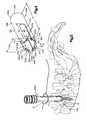
- FIG. 2is a perspective view of the spine with the implant of FIG. 1 inserted in a vertebrae;
- FIG. 3Ais a perspective view of an exemplary embodiment of an insertion guide of the present invention attached to the implant of FIG. 1 ;
- FIG. 3Bis an exploded view of the insertion guide of FIG. 3A and the implant of FIG. 1 ;
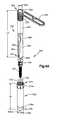
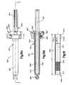
- FIG. 4is a perspective view of an alternative exemplary embodiment of an insertion guide
- FIG. 4Ais an exploded view of another alternative exemplary embodiment of an insertion guide
- FIG. 4Bis a perspective view of the guide of FIG. 4A with an outer sleeve in a first position
- FIG. 4Cis a perspective view of the guide of FIG. 4A with an outer sleeve in a second position;
- FIG. 4Dis a perspective view of an end of the insertion guide of FIG. 4C ;
- FIG. 4Eis a perspective view of an exemplary embodiment of a holder
- FIG. 4Fis a perspective view of an exemplary embodiment of the holder of FIG. 4E being used with the insertion guide of FIG. 4A ;
- FIG. 5is a perspective view the assembly of FIG. 3A attached to the spine;
- FIG. 6is a perspective view of a second assembly attached to the spine
- FIG. 7is a perspective view of a third assembly attached to the spine
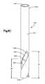
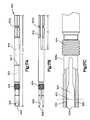
- FIG. 8Ais a perspective view of an exemplary embodiment of a guide sleeve of the present invention.
- FIG. 8Bis a cross-sectional view of the guide sleeve of FIG. 8A along A-A;
- FIG. 8Cis a perspective view of an alternative exemplary embodiment of a guide sleeve of the present invention.
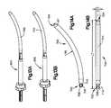
- FIG. 9is a perspective view of an exemplary embodiment of a fixation rod and holding instrument of the present invention.
- FIG. 9Ais a perspective view of an alternative exemplary embodiment of a fixation rod and holding instrument of the present invention.
- FIG. 9Bis a perspective view of another alternative exemplary embodiment of a fixation rod and holding instrument of the present invention.
- FIG. 10Ais a partial cross-sectional side view of the fixation rod of FIG. 9 ;
- FIG. 10Bis an enlarged view of the cross-section of FIG. 10A ;
- FIG. 11Ais a side view of an exemplary embodiment of an outer member of the holding instrument of FIG. 9 ;
- FIG. 11Bis a cross-sectional view of the outer member of FIG. 11A along B-B;
- FIG. 12Ais a side view of an exemplary embodiment of an inner member of the holding instrument of FIG. 9 ;
- FIG. 12Bis an enlarged view of an end of the inner element of FIG. 12A ;
- FIG. 13Ais a perspective view of an alternative exemplary embodiment of a fixation rod and holding instrument of the present invention with the holding instrument in a first position;
- FIG. 13Bis a perspective view of the fixation rod and holding instrument of FIG. 13A with the holding instrument in a second position;
- FIG. 14Ais a side view of an exemplary embodiment of the fixation rod of FIGS. 13A and 13B ;
- FIG. 14Bis a top view of the fixation rod of FIG. 14A ;
- FIG. 15Ais a side view of the holding instrument of FIGS. 13A and 13B ;
- FIG. 15Bis a cross-sectional view of the holding instrument of FIG. 15A along C-C;
- FIG. 16is a cross-sectional view of an exemplary embodiment of an outer sleeve of the holding instrument of FIG. 15A along C-C;
- FIG. 17Ais a side view of an exemplary embodiment of an inner sleeve of the holding instrument of FIGS. 15A and 15B ;
- FIG. 17Bis a top view of the inner sleeve of FIG. 17A ;
- FIG. 17Cis an enlarged view of an end portion of the inner sleeve of FIG. 17B ;
- FIG. 18is a side view of an exemplary embodiment of an elongated member of the holding instrument of FIGS. 15A and 15B ;
- FIG. 19Ais a cross-sectional view of an exemplary embodiment of an actuation mechanism of the holding instrument of FIG. 15A along D-D;
- FIG. 19Bis a side view of an exemplary embodiment of a retaining member of the actuation mechanism of FIG. 19A ;
- FIG. 19Cis a cross-sectional view of the retaining member of FIG. 19B along E-E;
- FIG. 19Dis another cross-sectional view of the actuation mechanism of FIG. 15A along D-D without the retaining member;
- FIG. 19Eis a cross-sectional view of the actuation mechanism of FIG. 19D along F-F;
- FIG. 20Ais a partial cross-sectional top view of the fixation rod and holding instrument of FIG. 13A ;
- FIG. 20Bis an enlarged view of a portion of FIG. 20A ;
- FIG. 21Ais a partial cross-sectional top view of the fixation rod and holding instrument of FIG. 13B ;
- FIG. 21Bis an enlarged view of a portion of FIG. 21A ;
- FIG. 22Ais a perspective view of an exemplary embodiment of the fixation rod and holding instrument of FIG. 13B as the fixation rod is inserted through a first assembly of FIG. 3A ;
- FIG. 22Bis a perspective view of the assembly of FIG. 3A with the guide sleeve in a first orientation within the assembly;
- FIG. 22Cis a cross-sectional view of the assembly of FIG. 22B positioned within the body;
- FIG. 23Ais a perspective view of an exemplary embodiment of the fixation rod and holding instrument of FIG. 13B as the fixation rod is inserted into the body;
- FIG. 23Bis a perspective view of the assembly of FIG. 3A with the guide sleeve in a second orientation within the assembly;
- FIG. 24is a perspective view of the fixation rod and holding instrument of FIG. 13A as the fixation rod and holding instrument are moved farther into the body;
- FIG. 25is a perspective view of the spine and assemblies of FIG. 3A after a fixation rod has been positioned in the implants of FIG. 1 ;
- FIG. 26is a perspective view of an exemplary embodiment of a spinal fixation system.
- the method of spinal fixation of the present inventionmay be performed using various instrumentation, including a plurality of implants (e.g., screws 100 ), a plurality of insertion guides 200 , 300 , 350 , a sleeve 400 , 416 , a rod (e.g., a fixation rod 500 , 550 , 570 , 700 ) and a holding instrument 600 , 650 , 670 , 800 .
- a plurality of implantse.g., screws 100
- a plurality of insertion guides 200 , 300 , 350e.g., a sleeve 400 , 416
- a rode.g., a fixation rod 500 , 550 , 570 , 700
- a holding instrument 600e.g., 650 , 670 , 800 .
- the instrumentsare described herein as being used in connection with spinal fixation procedures, one of ordinary skill in the art will readily appreciate that the instruments may be used in any other parts of the body (e.g., a long bone) to perform a fixation procedure. Thus, the location is not intended to be limiting in any way. In addition, the instruments may be used singularly or in combination with the other instruments described or other instruments that are not described herein. And, while the procedure discussed herein is performed using a posterior approach, those skilled in the art will recognize that the method and instrumentation may be adapted for any type of approach (e.g., posterio-lateral, lateral, anterior, anterio-lateral).
- a radiographic imagemay be taken of the spine, including the vertebrae which are to receive implants such as, for example, pedicle screws and fixation spinal rods.
- implantssuch as, for example, pedicle screws and fixation spinal rods.
- one or more insertion pointsmay be located on a patient's back.
- a surgeonmay make an incision in a patient's back to form an opening.
- the incisionmay have a length, for example, between about 1 cm and about 10 cm and, more preferably, between about 1.5 cm and about 5 cm.
- a smaller incisionmay be used where each insertion guide may be inserted through its own incision and a larger incision may be used where more than one insertion guide may be inserted through a single incision.
- the implantsare inserted into pedicles of the spine and, thus, the incisions are offset from the central spinous process by, for example, about 15 to about 35 mm.
- a set of implantsmay be used on each side of the spinous process.
- a guide wire(not shown) may be inserted though the incision and into a vertebrae.
- a surgical mallet or other impaction instrument(not shown) may be used to strike the guide wire such that the guide wire may be anchored to the vertebra (e.g., into the pedicle of the vertebra).
- the guide wiremay be used to guide various devices and/or implants into a patient and towards the spine.
- the guide wiremay be used to guide dilators, insertion guides, drill bits, screwdrivers, and/or implants (e.g., bone screws) to a location on the spine.
- any device described hereinmay be inserted into a patient without the use of the guide wire and/or passageways to the spine maybe formed without the use of the guide wire. It will be appreciated by those skilled in the art that, in some methods, a guide wire may be inserted through an incision after a passageway has been created to the spine.
- the incisionmay be dilated by, for example, sequential dilation. If a guide wire is first inserted through the incision, dilators may be inserted over the guide wire. If no guide wire is used, one or more dilators may be inserted directly through the skin and tissue. Dilation may be performed, through tissue (e.g., through a muscle), in between tissue segments (e.g., muscle segments) or in between tissue and the spine. It will be understood by those skilled in the art that dilation of an incision may be performed using any number of devices.
- a surgeonmay insert his/her finger(s) through the incision into the underlying tissue to dilate or dissect muscle and tissue in order to create a cleavage or space through tissue, in between tissue sections (e.g., between the multifidus and the longisimus muscle) or in between tissue and the spine.
- tissue sectionse.g., between the multifidus and the longisimus muscle
- the surgeonmay create a passageway to the vertebrae and/or palpate anatomical landmarks (e.g., facet joint).
- the methods described abovemay be repeated to create additional passageways to the spine.
- a smaller openingmay be used where each insertion guide may be inserted through its own opening and a larger incision(s) may be used where more than one insertion guide may be inserted through the same opening.
- the opening of the passagewaymay have a diameter, for example, between about 0.5 cm and about 3 cm and, more preferably, between about 1 cm and about 2 cm. It should be noted that the opening may be any shape, for example, oval, circular, egg-shaped, square, rectangular, polygonal or other shapes.
- an entire proceduremay be performed through a single dilated passageway.
- a proceduremay be performed through a cannula or a retractor, which may be expanded after insertion into the body, such as disclosed in U.S. patent application Ser. No. 10/917,560, filed Aug. 13, 2004, entitled Multiple-Blade Retractor, the entire content of which is hereby incorporated by reference.
- a cannula, retractor or insertion guidemay be placed into the body either over a dilator or directly into the passageway.
- the opening of the passagewaymay have a diameter, for example, between about 1.0 cm and about 12 cm and, more preferably, between about 3 cm and about 8 cm.
- a drill, awl and/or probemay be used to create an opening in one or more vertebrae.
- An implante.g., screw 100 of FIG. 1
- a screw 100may be passed through the passageway and may be inserted into the opening in the vertebrae using a screwdriver.
- a screw 100may be inserted into each pedicle of two or more adjacent vertebrae.
- the screw 100may be self threading and/or self tapping so that a tap (if used) may be unnecessary and the screw 100 may be screwed directly into the vertebrae using, for example, a screwdriver.
- the screw 100may comprise a shaft portion 102 and a head portion 104 operably connected to the shaft portion 102 .
- the shaft portion 102may be threaded.
- the screw 100may be polyaxial such that the head portion 104 may articulate and may be rotatable with respect to the shaft portion 102 (e.g., the head 104 may move about more than one axis; a polyaxial screw).
- the shaft 102 and head portion 104may be fixed with respect to each other.
- the shaft 102may have a bore 106 passing therethrough so that the screw 100 may be positioned over a guide wire.
- the head portion 104may have a channel 108 which may be U-shaped and may receive a fixation rod.
- the head portion 104may also have inner threads 110 for receiving an end cap 150 ( FIG. 26 ) so that a fixation rod may be held in the channel 108 between the end cap and the surface 112 a , 112 b of the channel 110 .
- Other end caps and means of holding the spinal rod and/or locking the shaft portion with respect to the head portionmay be implemented.
- a groove or recess 114may be incorporated into the head 104 so that an insertion guide may be attached thereto. It is contemplated, however, that any screw may be used so long as the screw incorporates or may be attached to a rod receiving channel sized and configured to receive a fixation rod.
- the shaft 102 and head portion 104may be inserted into the body as a single unit, in other embodiments, the shaft 102 and head portion 104 may be inserted separately. In such an embodiment, the shaft 102 may be inserted into a vertebrae. Thereafter, the head portion 104 may be attached to the shaft. In such an embodiment, the head portion 104 may be attached to an insertion guide 200 , 300 , 350 and/or other instrument so that the head portion 104 and the insertion guide 200 , 300 , 350 and/or other instrument may be inserted into the body as a single unit or assembly.
- the head portion 104may be attached and/or snapped onto the shaft 102 using the insertion guide 200 , 300 , 350 and/or other instrument (e.g., a pusher) to provide the surgeon with leverage for exerting force onto the head portion 104 .
- a pushere.g., a pusher
- the screw 100may be attached to an insertion guide 200 , 300 , 350 prior to insertion into the patient's body so that the screw and insertion guide 200 , 300 , 350 may be inserted into the patient as a single unit.
- a toole.g., screwdriver
- an insertion guide 200 , 300 , 350may be positioned in the body before the screw 100 .
- One or more toolsmay be inserted through the insertion guide 200 , 300 , 350 to create an opening in a vertebrae (e.g., an opening in the pedicle of a vertebrae).
- a screw 100may then be inserted down the insertion guide 200 , 300 , 350 , may be attached to the distal end of the insertion guide 200 , 300 , 350 and inserted into a vertebrae using a screwdriver.
- a screwdriver(not shown) may also be positioned within the insertion guide 200 , 300 , 350 and may engage the screw 100 so that the screw 100 , insertion guide 200 , 300 , 350 and screwdriver may be inserted into the body as a single unit.
- the screwdrivermay be removed, leaving the screw 100 and insertion guide 200 , 300 , 350 positioned in the body.
- the screw 100 , insertion guide 200 , 300 , 350 and/or other tool(s)e.g., drill, screwdriver
- other tool(s)e.g., drill, screwdriver
- insertion guidee.g., insertion guide 200 , 300 , 350
- the type of insertion guidewhich may be used in a procedure depends on, for example, the preference of the surgeon, the anatomy of the body and/or the requirements of the surgical procedure.
- any configuration of an insertion guidemay be used so long as a fixation rod may be inserted therethrough and the insertion guide may be operably associated with the screw 100 or other implant.
- an insertion guidemay be inserted directly through a passageway in a patient without the use of any additional instruments.
- the insertion guidemay perform the function of dilating/retracting an opening.
- an insertion guidemay be used to move (e.g., rotate) the head portion 104 of the screw 100 so that an operator may align the channels 108 of multiple screws 100 which may be inserted into adjacent vertebrae. In this way, a fixation rod may be inserted into screws 100 positioned in adjacent vertebrae.
- the insertion guide 200 , 300 , 350may allow a surgeon to directly visualize the orientation of the head portion 104 of the screw 100 . As such, a surgeon may be able to verify the location of a fixation rod in the channel 108 .
- the insertion guidemay have a light source (not shown) integral therewith or attached thereto.
- the insertion guidemay have a suction-irrigation system (not shown) to remove fluid and/or tissue, which may be obstructing a surgeon's view into the insertion guide 200 , 300 , 350 and/or may be obstructing a view of a surgical site.
- a microscope or endoscopemay also be attached to the insertion guide 200 , 300 , 350 to provide an enhanced view of a surgical site.
- the insertion guide 200 , 300 , 350may be connected to a table mount, which may be attached, for example, to an operating table and may hold the insertion guide 200 , 300 , 350 in place with respect to the patient, thereby eliminating the need for a surgeon or a nurse to hold the insertion guide 200 , 300 , 350 during surgery.
- the insertion guide 200 , 300 , 350 and its componentsmay be made, for example, of metal, ceramic, plastic, rubber, a combination of materials or a composite material.
- the insertion guide 200 , 300 , 350 and its componentsmay be made from stainless steel, titanium, aluminum, an alloy, carbon fiber composite, or a polymer (e.g., polyvinyl chloride (PVC), polyethylene, polyesters of various sorts, polycarbonate, Teflon coated metal, polyetherether ketone (PEEK), or ultra high molecular weight polyethylene (UHMWPE)).
- PVCpolyvinyl chloride
- PEEKpolyetherether ketone
- UHMWPEultra high molecular weight polyethylene
- the insertion guides 200 , 300 , 350may have a non-glare or lubricious coating and/or may be radiolucent or radioopaque.
- the material used to make the insertion guide 200 , 300 , 350may be made, for example, by casting, extrusion, injection molding, compression molding, forging, machining, or transfer molding.
- the insertion guide 200may include a first section or member 202 and a second section or member 204 which may be attachable to each other to form a tube with a bore 205 therethrough.
- the bore 205may be sized and configured to receive the head portion 104 of the screw 100 and may have a dimension D of between about 8 mm and about 20 mm, more preferably, between about 9 mm and about 16 mm and, most preferably, between about 10 mm and about 14 mm.
- the bore 205may have a proximal opening 205 a and a distal opening 205 b .
- first and second sections 202 , 204may be any shape such that the first and second sections 202 , 204 may form a tube which may be, for example, cylindrical, oval, square, rectangular or other polygon (e.g., the sections 202 , 204 may be crescent shaped, U-shaped, V-shaped).
- the first section 202may have a proximal end 206 , a distal end 208 , a first ring member 210 which may be positioned between the proximal end 206 and the distal end 208 , and a first longitudinal slot 212 .
- the second section 204may have a proximal end 214 , a distal end 216 , a second ring member 218 which may be positioned at the proximal end 214 , and a second longitudinal slot 220 .
- the first and second longitudinal slot 212 , 220may extend from the distal end 208 towards the proximal end 206 .
- the first and second longitudinal slots 212 , 220may be sized and configured to receive a fixation rod therethrough.
- the first and second longitudinal slots 212 , 220may have a width W between about 3 mm and about 7 mm, more preferably, between about 5 mm and about 6.5 mm and, most preferably, between about 5.5 mm and about 6 mm.
- the first and second longitudinal slots 212 , 220may have a height H, for example, between about 10 mm and about 100 mm, more preferably, between about 20 mm and about 80 mm and, most preferably, between about 30 mm and about 60 mm. It should be noted that the first and second longitudinal slots 212 , 220 may have the same or different width W and/or height H.
- the first and second section 202 , 204may be selectively engageable to each other.
- the first section 202may have one or more protrusions 222 which may engage one or more receiving portions 224 of the second section 204 .
- the protrusions 222 and receiving portions 224may be located anywhere between the proximal ends 206 , 214 and distal ends 208 , 216 .
- the protrusions 222 and receiving portions 224may be located proximate the distal ends 208 , 216 .
- the protrusions 222 and receiving portions 224may be any shape so long as the protrusions 222 and receiving portions 224 may be used to fix the first and second sections 202 , 204 with respect to each other.
- the protrusions 222 and receiving portions 224may correspond in shape.
- the protrusions 222may have a width PW of, for example, between about 1 mm and about 6 mm, more preferably, between about 2 mm and about 5 mm and, most preferably, between about 3 mm and about 4 mm.
- the receiving portion 224may have a corresponding width.
- the protrusions 222 and the receiving portions 224may be straight (e.g., rectangular) or may be slanted (e.g., a parallelogram) such as shown in FIGS. 3A and 3B .
- the protrusions 222 and receiving portions 224may be slanted allowing for ease of engagement/disengagement of the first and second sections 202 , 204 and facilitating engagement/disengagement of the guide 200 with the head portion 104 of the screw 100 .
- the distal end 216 of the second section 204may be moved through the first ring member 210 of the first section 202 until the proximal end 206 of the first section 202 may be positioned through the second ring member 218 of the second section 204 .
- the rings 210 , 218may be positioned adjacent each other or may be a distance from each other.
- the rings 210 , 218may be sized and configured so that an operator may use his/her hand and/or fingers to move the sections 202 , 204 together or separate the sections 202 , 204 by, for example, positioning the ring 218 against a thumb or in the palm of a hand and/or grasping the ring 210 with a finger.
- the rings 210 , 128may have a textured (e.g., knurled) surface and/or may have grooves 210 a , 218 a to enhance a surgeon's grip on the sections 202 , 204 .
- the protrusion 222may engage the receiving portions 224 so that the sections 202 , 204 may be fixed with respect to each other.
- the two-piece constructionmay permit the distal ends 208 , 216 of the first and second sections 202 , 204 , respectively, to be flexible and, thus, may enable an operator to attach, snap and/or clip the insertion guide 200 (i.e., the distal ends 208 , 216 of the sections 202 , 204 , respectively) to or remove the insertion guide 200 from the head portion 104 .
- the insertion guide 200When the insertion guide 200 is in the assembled condition, the insertion guide 200 may have a length L of, for example, between about 50 mm and about 300 mm, more preferably, between about 80 mm and about 250 mm and, most preferably, between about 100 mm and about 200 mm, and an outer dimension OD of, for example, between about 5 mm and about 25 mm, more preferably, between about 10 mm and about 20 mm and, most preferably, between about 12 mm and about 18 mm.
- Lof, for example, between about 50 mm and about 300 mm, more preferably, between about 80 mm and about 250 mm and, most preferably, between about 100 mm and about 200 mm
- an outer dimension ODof, for example, between about 5 mm and about 25 mm, more preferably, between about 10 mm and about 20 mm and, most preferably, between about 12 mm and about 18 mm.
- the distal ends 208 , 216may have flanges 226 , 228 , respectively, which may extend into the bore 205 and may be received in the groove 114 of the screw head 104 .
- Such a constructionmay prevent the insertion guide 200 from being separated from the head portion 104 of the screw 100 .
- the flange 228may have one or more prongs 228 a which may extend into the bore 205 and/or the flange 226 may have one or more prongs (not shown) which may also extend into the bore 205 .
- the prongs 228 amay be positioned on a portion 228 b which may extend into the longitudinal slot 220 .
- the prongsmay be positioned on a portion which may extend into the longitudinal slot 212 .
- the retaining portions 228 amay be positioned against the surfaces 104 a , 104 b of the head portion 104 and the retaining portions (if present) of the flange 226 may positioned against the identical surfaces 104 a , 104 b on the other side of the head portion 104 .
- such a configurationmay align the U-shaped portions of the channel 108 with the first and second longitudinal slots 212 , 220 so that a fixation rod may be moved along the first and second slots 212 , 220 and into the channel 108 of the screw 100 .
- such a constructionmay prevent the insertion guide 200 from rotating relative to the head portion 104 and may allow an operator to move (e.g., rotate) the head portion 104 of the screw 100 with the insertion guide 200 during a surgical procedure while the slots 212 , 220 and channel 108 remain aligned.
- the insertion guide 300may include a body portion 302 having a bore 304 , a proximal end 306 , a distal end 308 , a proximal opening 300 a , a distal opening 300 b , a first longitudinal slot 310 and a second longitudinal slot 312 .
- the bore 304may be sized and configured to receive the head portion 104 of the screw 100 and may have an inner dimension similar to the dimension D of the bore 205 of FIG. 3A .
- the insertion guide 300may have a length L 2 of, for example, between about 50 mm and about 300 mm, more preferably, between about 80 mm and about 250 mm and, most preferably, between about 100 mm and about 200 mm, and an outer dimension OD 2 of, for example, between about 5 mm and about 25 mm, more preferably, between about 10 mm and about 20 mm and, most preferably, between about 12 mm and about 18 mm.
- the first and second longitudinal slot 310 , 312may extend from the distal end 308 towards the proximal end 306 .
- the first and second longitudinal slots 310 , 312may be sized and configured to receive a fixation rod therethrough.
- the first and second longitudinal slots 310 , 312may have a width W 2 between about 3 mm and about 7 mm, more preferably, between about 5 mm and about 6.5 mm and, most preferably, between about 5.5 mm and about 6 mm.
- first and second longitudinal slots 310 , 312may have a height H 2 , for example, between about 10 mm and about 100 mm, more preferably, between about 20 mm and about 80 mm and, most preferably, between about 30 mm and about 60 mm. It should be noted that the first and second longitudinal slots 310 , 312 may have the same or different widths W 2 and/or height H 2 .
- the insertion guide 300may have at least one additional slot 314 , 316 which may be located between the longitudinal slots 310 , 312 .
- the slots 314 , 316may be sized and configured so as to form a plurality of flexible prongs 318 .
- the prongs 318may flex to enable an operator to engage the insertion guide 300 with (and disengage the insertion guide 300 from) the head portion 104 of a screw 100 (i.e., so that the guide 300 may be clipped onto or removed from the head portion 104 ).
- the slots 314 , 316may have a width W 3 , for example, between about 0.5 mm and about 6 mm, more preferably, between about 1 mm and about 5 mm and, most preferably, between about 2 mm and about 4 mm. Moreover, the slots 314 , 316 may have a height H 3 , for example, between about 10 mm and about 100 mm, more preferably, between about 20 mm and about 80 mm and, most preferably, between about 30 mm and about 60 mm. It should be noted that the slots 314 , 316 may have the same or different width W 3 and/or height H 3 .
- the distal end 308 of the insertion guide 300may have flanges 320 , which may extend into the bore 304 and may be received in the groove 114 of the screw head 104 .
- the flanges 320may each have one or more prongs 322 a , 322 b which may also extend into the bore 304 .
- the prongs 322 a , 322 bmay be positioned on a portion 323 a , 323 b which may extend into the longitudinal slots 310 , 312 .
- the retaining portions 322 amay be positioned against the surfaces 104 a , 104 b and the retaining portions 322 b may be positioned against identical surfaces on the opposite side of the head portion 104 .
- Such a configurationmay align the U-shaped portions of the channel 108 with the first and second longitudinal slots 310 , 312 so that a fixation rod may be moved along the first and second slots 310 , 312 and into the channel 108 of the screw 100 .
- such a constructionmay prevent the insertion guide 300 from rotating relative to the head portion 104 and may allow an operator to move the head portion 104 of the screw 100 with the insertion guide 300 during a surgical procedure while the slots 212 , 220 and channel 108 remain aligned.
- FIG. 4Aillustrates an alternative embodiment of an insertion guide 350 .
- the insertion guide 350may have an inner sleeve 351 and an outer sleeve 352 .
- the inners sleeve 351may have a distal end 353 , a proximal end 354 , and a bore 356 passing from the distal end 353 to the proximal end 354 .
- the bore 356may be sized and configured to receive the head portion 104 of the screw 100 and may have an inner dimension ID 4 of, for example, between about 8 mm and about 20 mm, more preferably, between about 9 mm and about 16 mm and, most preferably, between about 10 mm and about 14 mm.
- the inner sleeve 351may have a length L 5 of, for example, between about 50 mm and about 300 mm, more preferably, between about 80 mm and about 250 mm and, most preferably, between about 100 mm and about 200 mm, and an outer dimension OD 8 of, for example, between about 5 mm and about 25 mm, more preferably, between about 10 mm and about 20 mm and, most preferably, between about 12 mm and about 18 mm.
- the inner sleeve 351may have body portion 355 , and first and second arms 362 , 364 extending from the body portion 355 .
- the arms 362 , 364may have a first longitudinal slot 366 and a second longitudinal slot 368 therebetween such that the arms 362 , 364 may be flexible relative to each other.
- An integral or detachable handle 369may be attached to the inner sleeve 351 (e.g., proximate the proximal end 354 ) and may be used by a surgeon to manipulate the insertion guide 350 during a surgical procedure.
- the inner sleeve 351may have an actuating mechanism (e.g., threads 370 , a ratchet mechanism), which may extend along a portion of the inner sleeve 358 .
- an actuating mechanisme.g., threads 370 , a ratchet mechanism
- the threads 370may extend along the body 355 from the proximal end 354 towards the distal end 353 .
- the outer sleeve 352may be positioned over the inner sleeve 351 and may have an inner dimension ID 5 which may be sized to fit over the inner sleeve 351 .
- the outer sleevemay have a length L 6 of, for example, between about 30 mm and about 200 mm, more preferably, between about 50 mm and about 160 mm and, most preferably, between about 75 mm and about 125 mm and an outer dimension OD 9 of, for example, between about 6 mm and about 30 mm, more preferably, between about 10 mm and about 25 mm and, most preferably, between about 12 mm and about 20 mm.
- the outer sleeve 352may also have an engagement member (e.g., internal threads 372 ) which may engage the threads 370 of the inner sleeve 351 .
- An operatormay move the outer sleeve 352 along the inner sleeve 351 , for example, by rotating the outer sleeve 352 about the inner sleeve 351 (i.e., about axis 350 a ).
- a knob 374 amay be provided to enhance a surgeon's grip of the outer sleeve 352 to facilitate rotation.
- the outer sleeve 352may have a first position on the inner sleeve 351 ( FIG.
- proximal end 374 of the outer sleeve 352may be positioned proximate the proximal end 354 of the inner member 351 (i.e., the proximal end 374 may be a first distance from the proximal end 354 ), and a second position ( FIG. 4C ), where the proximal end 374 of the outer sleeve 352 is moved farther away from the proximal end 354 of the inner member 351 (i.e., the proximal end 374 may be a second distance from the proximal end 354 and the second distance may be greater than the first distance).
- the head portion 104 of a screw 100may be inserted in between arms 362 , 364 .
- the distal ends 362 a , 364 a of the arms 362 , 364may have flanges 376 , which may extend into the bore 356 and may be received in the groove 114 of the screw head 104 . It should be noted that only one arm may have a flange 376 . The flange(s) 376 may prevent the insertion guide 350 from being separated from the head portion 104 of the screw 100 .
- the flange 376may extend along the entire distal ends 362 a , 364 a of the arms 362 , 364 , respectively, or may be positioned only on a portion of the arms 362 , 364 .
- each flange 376may have one or more extending portions 378 which may extend into the longitudinal slots 366 and/or 368 and which may be positioned in a retaining portion 380 of the head portion 104 proximate the channel 108 .
- Such a configurationmay prevent the insertion guide 350 from rotating relative to the head portion 104 of the screw 100 .
- any configuration which prevents the guide 350 from rotating relative to the screw 100may be used.
- the outer sleeve 352may be moved from the first position ( FIG. 4B ) to the second position ( FIG. 4C ), thereby firmly engaging the arms 362 , 364 around the head portion 104 .
- the outer sleeve 352may have a tapered end 376 a to facilitate introduction of the outer sleeve 352 and/or the insertion guide 350 into the body.
- a holder 382may be used by a surgeon to connect a screw 100 and insertion guide 350 .
- the holder 382may have a body 384 , an opening 386 for receiving the screw 100 , and a fixing member 388 for holding the screw 100 in a fixed position relative to the holder 382 (i.e., so that the head portion 104 of the screw 100 may be prevented from rotating relative to the holder 382 ).
- the fixation member 388may be a rod and may be rotatably connected to the holder 382 about a pivot 389 .
- the components of the holder 382may be made, for example, of metal, ceramic, plastic, rubber, a combination of materials or a composite material.
- the componentsmay be made from stainless steel, titanium, aluminum, an alloy, carbon fiber composite, or a polymer (e.g., polyvinyl chloride (PVC), polyethylene, polyesters of various sorts, polycarbonate, Teflon coated metal, polyetherether ketone (PEEK), or ultra high molecular weight polyethylene (UHMWPE)).
- a polymere.g., polyvinyl chloride (PVC), polyethylene, polyesters of various sorts, polycarbonate, Teflon coated metal, polyetherether ketone (PEEK), or ultra high molecular weight polyethylene (UHMWPE)).
- PVCpolyvinyl chloride
- PEEKpolyetherether ketone
- UHMWPEultra high molecular weight polyethylene
- Various factorsmay be considered when determining the material used to make the components, including ability to withstand sterilization/cleaning (e.g., using an autoclave; cleaning products used for sterilization in hospitals), weight, durability, ability to withstand forces exerted thereon, resistance to staining (e.g., from blood or substances used in surgery) and the ability to grip the components, particularly with latex gloves which are generally used during surgery.
- sterilization/cleaninge.g., using an autoclave; cleaning products used for sterilization in hospitals
- weighte.g., weight, durability, ability to withstand forces exerted thereon, resistance to staining (e.g., from blood or substances used in surgery) and the ability to grip the components, particularly with latex gloves which are generally used during surgery.
- the holder 382may also have a counterbore 390 which may be positioned adjacent the opening 386 and may receive the distal end 353 of the inner sleeve 351 .
- the counterbore 390may be non-circular so that the insertion guide 350 may be prevented from rotating within the counterbore 390 when inserted therein.
- the holder 382may also be configured to be operably attached to another object (e.g., operating table or tool kit) by a fastener (e.g., bolt, screw, Velcro).
- a fastenere.g., bolt, screw, Velcro
- the holder 382may be made of a heavy material so that the holder 382 is weighed down.
- a screw 100may be inserted through the opening 386 so that the head portion 104 of the screw 100 may rest against a ledge 392 and the shaft 102 may be positioned through the hole 386 . Thereafter, as shown in FIG. 4F , the retaining member 388 may be rotated so that an end portion 394 of the retaining member 388 may be positioned within the channel 108 of the head portion 104 , thus, fixing the screw 100 with respect to the holder 382 . An insertion guide 350 may then be connected to the head portion 104 .
- the arms 362 , 364 of the inner sleeve 351may be positioned around the head portion 104 so that the retaining member 388 may be positioned through one or both longitudinal slots 366 , 368 .
- the outer sleeve 352may then be rotated so that the distal end 376 of the outer sleeve 352 moves towards the distal end 353 of the inner sleeve 351 until the arms 362 , 364 firmly engage the head portion 104 .
- the screw 100 and insertion guide 350may subsequently be removed from the holder 382 and inserted into the body as a single unit. This step may be repeated for additional insertion guides 350 . It should be noted, however, that a holder 382 may be unnecessary and a surgeon may attach the screw 100 and insertion guide 350 using only his/her hands/fingers.
- FIG. 5illustrates a screw 100 positioned in the pedicle of a first vertebrae V 1 with an insertion guide (e.g., insertion guide 200 a ) attached thereto and extending out of a first incision I 1 in the skin.
- insertion guidee.g., guide 200 a
- FIG. 5is for illustrative purposes only and any insertion guide (e.g., guide 300 ) may be attached to a screw 100 at any vertebral body.
- the method of inserting screw 100 and insertion guide 200 , 300 , 350may be repeated one or more times. For example, as shown in FIGS.
- a screw 100may be inserted in a second and third vertebrae V 2 , V 3 (e.g., in the pedicle) with insertion guides (e.g., insertion guides 200 b , 200 c ) attached thereto and extending out of a second and third incision 12 , 13 , respectively, in the skin.
- insertion guidese.g., insertion guides 200 b , 200 c
- Such a constructionmay allow for spinal fixation of the three vertebrae V 1 , V 2 and V 3 . While FIGS.
- 5 , 6 and 7illustrate a procedure being performed through three separate incision 11 , 12 and 13 , it should be noted that the three screws 100 and insertion guides may be positioned in the same incision, cannula and/or retractor such that a spinal fixation procedure may be performed through one larger incision.
- a guide sleeve 400 , 416may be positioned through at least one insertion guide.
- the guide sleeve 400may be inserted into insertion guide 200 a , 200 b or 200 c .
- the guide sleeve 400 , 416would be inserted in one of the end insertion guides 200 a or 200 c .
- the guide sleeve 400 , 416may be sized and configured to fit within the bore 205 , 304 , 356 of the insertion guide 200 , 300 , 350 .
- the sleeve 400may have an outer dimension OD 3 of, for example, between about 5 mm and about 22 mm, more preferably, between about 10 mm and about 18 mm and, most preferably, between about 12 mm and about 16 mm, and an inner dimension ID 3 of, for example, between about 4 mm and about 21 mm, more preferably, between about 9 mm and about 17 mm and, most preferably, between about 10 mm and about 15 mm.
- the sleeve 400may also have a length L 3 of, for example, between about 50 mm and about 350 mm, more preferably, between about 80 mm and about 270 mm and, most preferably, between about 100 mm and about 210 mm.
- the guide sleeve 400 , 416may be sized and configured to fit over the outside of the insertion guide 200 a , 200 b or 200 c .
- a guide sleeve 400 , 416may be positioned over the distal end 208 , 216 of the insertion guide 200 (or over the distal end 308 of insertion guide 300 or distal end 353 of inner sleeve 351 ) prior to insertion of the insertion guide 200 , 300 , 350 into the body. Thereafter, the insertion guide 200 , 300 , 350 and sleeve 400 , 416 may be inserted into the body as a single unit.
- the sleeve 400 , 416may be rotated about insertion guide 200 , 300 , 350 for reasons which will become apparent below.
- the sleeve 400 , 416may be made of two pieces which may be inserted over the outside of an insertion guide 200 , 300 , 350 and connected to each other.
- the sleeve 400 , 416may be made of two pieces connected by a hinge so that the sleeve 400 , 416 may be opened to fit around the insertion guide 200 , 300 , 350 and closed therearound.
- the sleeve 400 , 416may be inserted over the proximal end of an insertion guide (i.e., the portion of the insertion guide positioned outside the body) before or after the insertion guide is inserted into the body.
- the sleeve 400 , 416may be inserted over the proximal end 306 of the insertion guide 300 .
- the guide sleeve 400may include a body 402 which may have a longitudinal axis 401 , a proximal end 404 , a proximal opening 400 a , a distal end 406 , a distal opening 400 b and a bore 407 extending from the proximal end 404 to the distal end 406 .
- the length L 3 of the sleeve 400may be long enough such that the proximal end 404 of the sleeve 400 may protrude from the proximal end 214 , 306 , 354 of the insertion guides 200 , 300 , 350 , respectively.
- the distal end 406 of the guide sleeve 400may have a chamfered inner edge 406 c which may engage a corresponding chamfered edge 104 c of the head portion 104 of the screw 100 .
- the chamfered edges 104 c and 406 cmay be sloped in opposite directions so that the chamfered edges 104 c and 406 c may be positioned adjacent each other.
- the body 402may also have a first opening 408 , a second opening 410 , a first longitudinal opening 412 intersecting the first opening 408 and a second longitudinal opening 414 intersecting the second opening 410 .
- the first and second openings 408 , 410may be at an angle (e.g., perpendicular) with respect to the first and second longitudinal opening 412 , 414 , respectively.
- the first and second openings 408 , 410preferably are formed in a side wall 400 s of the generally cylindrical sleeve body 402 and are elongated preferably perpendicular to the longitudinal axis 401 of the sleeve body 402 .
- the first and second longitudinal openings 412 , 414preferably are formed in the side wall 400 s of the sleeve body 402 and extend in the direction of the longitudinal axis 401 of the sleeve body 402 .
- the first longitudinal opening 412 and second longitudinal opening 414may extend from the distal end 406 towards the proximal end 404 .
- the first opening 408is generally perpendicular to the first longitudinal opening 412 to form a generally L-shaped opening in the side wall 400 s of the sleeve body 402 .
- the second opening 410is generally perpendicular to the second longitudinal opening 414 to form a generally L-shaped opening the side wall 400 s of the sleeve body 402 .
- the first longitudinal opening 412is opposite (formed about 180° from) the second longitudinal opening 414 .
- the first and second openings 408 , 410have been shown and described as being generally perpendicular to the first and second longitudinal openings 412 , 414 , respectively, the first and second openings 408 , 410 may be formed at an angle from about 0° to about 180° with respect to the first and second longitudinal openings 412 , 414 , respectively, and may form different shapes other than a generally L-shaped opening.
- the first and second openings 408 , 410 and first and second longitudinal openings 412 , 414may be sized and configured to receive a fixation rod, more preferably, the width of the first and second opening 408 , 410 , as well as the width of the first and second longitudinal openings 412 , 414 may be slightly larger than the diameter of a spinal rod so that a spinal rod can be passed through the respective openings.
- the first longitudinal opening 412may have a height H 3 of, for example, between about 10 mm and about 100 mm, more preferably, between about 20 mm and about 80 mm and, most preferably, between about 30 mm and about 60 mm.
- the second longitudinal opening 414may have a height H 4 of, for example, between about 8 mm and about 100 mm, more preferably, between about 15 mm and about 70 mm and, most preferably, between about 20 mm and about 60 mm.
- the first and second longitudinal openings 412 , 414may have a width W 3 of, for example, between about 3 mm and about 7 mm, more preferably, between about 5 mm and about 6.5 mm and, most preferably, between about 5.5 mm and about 6 mm.
- the first and second longitudinal openings 412 , 414may have the same or different width W 3 .
- the first and second openings 408 , 410may have a width W 4 of, for example, between about 5 mm and about 30 mm, more preferably, between about 6 mm and about 20 mm and, most preferably, between about 8 mm and about 14 mm.
- the first and second openings 408 , 410may have the same or different width W 4 .
- the width W 3 of the first and second longitudinal openings 412 , 414may be the same as or different from the width W 4 of the first and second openings 408 , 410 .
- the guide sleeve 400may be made, for example, of metal, ceramic, plastic, rubber, a combination of materials or a composite material.
- the sleeve 400may be made from stainless steel, titanium, aluminum, an alloy, carbon fiber composite, or a polymer (e.g., polyvinyl chloride (PVC), polyethylene, polyesters of various sorts, polycarbonate, Teflon coated metal, polyetherether ketone (PEEK), or ultra high molecular weight polyethylene (UHMWPE)).
- PVCpolyvinyl chloride
- PEEKpolyetherether ketone
- UHMWPEultra high molecular weight polyethylene
- the sleeve 400may have a non-glare or lubricious coating and/or may be radiolucent or radioopaque.
- the material used to make the sleeve 400may be made, for example, by casting, extrusion, injection molding, compression molding, forging, machining, or transfer molding.
- FIG. 8Cillustrates an alternative embodiment of the sleeve, sleeve 416 .
- the sleeve 416may have a side wall 418 , a proximal end 418 a , a distal end 418 b , and a bore 419 therethrough extending from the proximal end 418 a to the distal end 418 b .
- the sleeve 416may have the same dimensions and may be made of the same material(s) as the sleeve 400 .
- the sleeve 416may have two spiral slots 420 , 422 .
- Slot 420may have a height H 5 which may be similar to the height H 3 and slot 422 may have a height H 6 which may be similar to the height H 4 . Moreover, the slots 420 , 422 may have the same width as the slots 412 , 414 . Similar to sleeve 400 , the sleeve 416 may be positioned through an insertion guide 200 a , 200 b , 200 c , preferably an end insertion guide 200 a or 200 c .
- a rod 500 , 550 , 570 , 700may be positioned into the insertion guide 200 c , through the proximal ends 420 a , 422 a of the slots 420 , 422 and into additional insertion guides 200 a , 200 b . Thereafter, the sleeve 416 may be rotated so that the rod 500 , 550 , 570 , 700 may be moved down the sleeve 416 towards the distal end 418 b of the sleeve 416 .
- the rod 500 , 550 , 570 , 700may be pushed down into the body (i.e., towards the screws 100 ) using a holding instrument 600 , 650 , 670 , 800 at the same time the sleeve 416 is being rotated. In this way, tissue may be moved by the rod 500 , 550 , 570 , 700 . It should be noted, however, that rotation of the sleeve 416 , by itself, may provide sufficient force on the rod 500 , 550 , 570 , 700 so that the rod 500 , 550 , 570 , 700 pushes tissue out of the way as the rod 500 , 550 , 570 , 700 moves down towards the screws 100 .
- a holding instrumentmay be used to insert a fixation or spinal rod through the guide sleeve 400 , 416 and insertion guides 200 , 300 , 350 and into the head portion 104 of a screw 100 .
- FIG. 9illustrates one embodiment of a spinal rod 500 and a holding instrument 600 .
- the rod 500 and/or holding instrument 600may be made, for example, of metal, ceramic, plastic, rubber, a composite material, or a combination of materials.
- the rod 500 and/or holding instrument 600may be made from stainless steel, titanium, aluminum, an alloy, carbon fiber composite, or a polymer (e.g., polyvinyl chloride (PVC), polyethylene, polyesters of various sorts, polycarbonate, Teflon coated metal, polyetherether ketone (PEEK), or ultra high molecular weight polyethylene (UHMWPE)).
- a polymere.g., polyvinyl chloride (PVC), polyethylene, polyesters of various sorts, polycarbonate, Teflon coated metal, polyetherether ketone (PEEK), or ultra high molecular weight polyethylene (UHMWPE)).
- PVCpolyvinyl chloride
- PEEKpolyetherether ketone
- UHMWPEultra high molecular weight polyethylene
- rod 500 and/or holding instrument 600or components thereof
- factorsmay be considered when determining the material used to make the rod 500 and/or holding instrument 600 (or components thereof), including ability to withstand sterilization/cleaning (e.g., using an autoclave; cleaning products used for sterilization in hospitals), weight, durability, ability to withstand forces exerted thereon, resistance to staining (e.g., from blood or substances used in surgery) and the ability to grip the components, particularly with latex gloves which are generally used during surgery.
- various methodsmay be used to make the rod 500 and/or holding instrument 600 (or components thereof), including casting, extrusion, injection molding, compression molding, forging, machining, or transfer molding. These same materials and methods may be used to make any rod and/or holding instruments (or components thereof) such as, for example, rod 700 and holding instrument 800 discussed in greater detail below.
- the rod 500may be a curved elongated member and may be made of a solid piece of material.
- the rodmay be a straight elongated member and/or may be hollow.
- the rod 500may have a proximal end 502 , a distal end 504 , and a cross-section which may be any shape (e.g., round, oval, square, rectangular or other polygon).
- the rod 500may be sized and configured to be inserted through the openings/slots in insertion guides 200 , 300 , 350 , guide sleeve 400 , 416 and into the channel 108 in the head portion 104 of a screw 100 .
- the rod 500may have an outer diameter OD 4 , for example, between about 3 mm and about 7 mm, more preferably, between about 5 mm and about 6.5 mm and, most preferably, between about 5.5 mm and about 6 mm.
- the length L 4 of the rod 500may be, for example, between about 30 mm and about 200 mm, more preferably, between about 35 mm and about 180 mm and, most preferably, between about 40 mm and about 150 mm, and the length L 4 of the rod 500 may be a factor of, for example, the number of screws 100 through which the rod 500 will be inserted and/or the distance in between screws 100 (which may be dictated by patient anatomy).
- the radius of the curvature R 1may be, for example, between about 50 mm and about 500 mm, more preferably, between about 80 mm and about 300 mm and, most preferably, between about 100 mm and about 200 mm.
- the distal end 504 of the rod 500may be round, blunted have a point and/or taper, which may help facilitate moving tissue around the distal end 504 as the rod 500 is inserted through the body.
- the distal end 504may have a radius of curvature R of, for example, between about 2 mm and about 15 mm, more preferably, between about 3 mm and about 12 mm and, most preferably, between about 5 mm and about 10 mm.
- the proximal end 502may have an receiving portion 506 for attaching to at least a portion (e.g., attachment portion 612 ) of the holding instrument 600 . As illustrated in FIG.
- the receiving portion 506may have a side wall 512 that forms a generally U-shaped configuration.
- the receiving portion 506may be sized and configured to engage the holding instrument 600 such that the rod 500 may rotate and/or pivot about 360 degrees relative to the holding instrument 600 about an axis 508 and/or may rotate and/or pivot about 100 degrees relative to the holding instrument 600 about an axis 510 .
- the side wall 512 of the receiving portion 506may have at least one bore 514 , which may extend entirely through the wall 512 or partially into the wall 512 (e.g., forming a recess or aperture).
- the bores 514may receive corresponding portions (e.g., hemispherical portions 616 ) of the holding instrument 600 .
- the recessmay be hemispherical in shape and may receive hemispherical portions 616 of the holding instrument 600 .
- the holding instrument 600may comprise an outer member 602 and an inner member 604 .
- the outer member 602may have a distal end 606 , a proximal end 608 and a passageway 610 which may extend from the distal end 606 to the proximal end 608 .
- the outer member 602may have an outer dimension OD 5 which may be sized and configured to be similar or identical to the outer dimension OD 4 of the rod 500 .
- the distal end 606may have an attachment portion 612 which may be nearly spherical or hemispherical in shape.
- the attachment portion 612may be sized and configured to be inserted into the receiving portion 506 of the rod 500 .
- the attachment portion 612may have a radius of curvature R 2 of, for example, between about 1 mm and about 6 mm, more preferably, between about 1.5 mm and about 4 mm and, most preferably, between about 2 mm and about 3 mm.
- a slit 614may pass through the attachment portion 612 and may extend from the distal end 606 towards the proximal end 608 .
- the slit 614may result in the attachment portion 612 having two spherical like or quadrant portions 616 .
- Such a constructionmay enable the attachment portion 612 to be flexible so that the attachment portion 612 may be inserted into the receiving portion 506 of the rod 500 and, in particular, so that the hemispherical portions 616 may be inserted and/or snapped into the bores (recesses/apertures) 514 of the rod 500 .
- the proximal end 608 of the holding instrument 600may have a enlarged portion 618 which may provide a gripping surface for an operator to manipulate the outer member 602 , the holding instrument 600 and/or the rod 500 .
- the enlarged portion 618may have one or more grooves 620 to provided an enhanced gripping surface for an operator.
- the enlarged portion 618may be textured (e.g., knurled) to provide an enhanced gripping surface.
- the passageway 610may have a engagement portion 622 , which may be at the proximal end 608 .
- the engagement portion 622may be a threaded portion and may be used to engage a corresponding engagement portion 624 (such as, for example, threads) of the inner member 604 .
- the inner member 604may comprise a distal end 626 , a proximal end 628 , and an engagement portion 624 between the distal end 626 and proximal end 628 .
- the inner member 604may have an outer dimension OD 5 which may be sized and configured such that the inner member 604 may be receiving in the passageway 610 of the outer member 602 and may be moveable therein, both rotationally and by axial sliding.
- the outer dimensions OD 6may be, for example, between about 2 mm and about 5 mm, more preferably, between about 2.5 mm and about 4.5 mm and, most preferably, between about 3 mm and about 4 mm.
- the distal end 626have a reduced dimension as compared with the outer dimension OD 6 of the inner member 604 .
- One way to accomplish thismay be to provide a bevel 630 along the length of the inner member 604 and reduce the dimension of the inner rod 604 in the distal direction after the bevel 630 .
- a tip 632may be formed at the distal end 626 and may be round, blunted, tapered, pointed or any other shape.
- the tip 632may have a radius of curvature R 3 of between about 0.3 mm and about 1.5 mm, more preferably, between about 0.5 mm and about 1.3 mm and, most preferably, between about 0.7 mm and about 1 mm.
- the proximal end 628 of the inner member 604may have an enlarged portion 634 which may provide a gripping surface for an operator to manipulate the inner member 604 , the outer member 602 , the holding instrument 600 and/or the rod 500 .
- the enlarged portion 634may have one or more grooves 636 to provided an enhanced gripping surface for an operator.
- the enlarged portion 634may be textured (e.g., knurled) to provide an enhanced gripping surface.
- the attachment portion 612 of the outer member 604may be positioned in the receiving portion 506 of the rod 500 .
- the inner member 604may be positioned within the passageway 614 of the outer member 602 and moved so that the engagement portion 624 of the inner member 604 may engage the engagement member 622 of the outer member 602 .
- Rotation of the inner member 604 in a first direction(e.g., clockwise) may move the distal portion 626 of the inner member 604 in between the hemispherical portions 616 .
- the distal portion 626may push the hemispherical portion 616 outward, into the bores 514 of the receiving portion 506 .
- Such a configurationmay prevent the rod 500 and the holding instrument 600 from separating from each other while, at the same time, may allow for the rod 500 and holding instrument 600 to rotate and pivot relative to each other.
- the inner member 604may be threaded farther into the outer member so that the tip 632 of the inner member 604 may extend beyond the distal most portion 606 of the outer member 602 .
- the tip 632may then be inserted into the recess 506 a or 506 b of the receiving portion.
- the holding instrument 600may be held at an angle with respect to the rod 500 such as shown in FIG. 9 .
- the axis 500 a of the rod 500may be aligned with the axis 600 a of the holding instrument 600 such as shown in FIG. 21A .
- the rod 500 and holding instrument 600may be separated from each other by rotating the inner member 604 in a second direction (e.g., counterclockwise) so that the distal end 626 of the inner member 604 may be moved away from the distal end 606 of the outer member 602 .
- a second directione.g., counterclockwise
- the attachment portion 612 of the outer member 602may be flexed and may be removed from the receiving portion 506 of the rod 500 .
- FIG. 9Aillustrates an alternative rod 550 and holding instrument 650 .
- the rod 550may have a engaging portion 552 which may be engaged by the holding instrument 650 .
- the holding instrument 650may have an inner sleeve 651 and an outer sleeve 652 .
- the inner sleeve 651may have a plurality of arms 654 (e.g., three arms) which may engage the engaging portion 552 .
- the engaging portion 552may be spherical in shape and the arms 654 may be positioned around the engaging portion 552 .
- the arms 654may have curved surfaces 656 which correspond to the shape of the engaging portion 552 .
- the outer sleeve 652may have a first position, where the distal end 652 a of the outer sleeve 652 may be positioned away from the arms 654 , and a second position (shown in FIG. 9A ), where the distal end 652 a of the outer sleeve 652 may be positioned proximate (e.g., over) the arms 654 .
- the arms 654may be attached to the engaging portion 552 when the outer sleeve 652 is in the first position.
- the arms 654may be clipped/snapped onto the engaging portion 552 .
- the rod 550may be pivotable relative to the holding instrument 650 about more than one axis.
- the outer sleeve 652may be moved from the first position to the second position. With the distal end 652 a of the outer sleeve 652 positioned over the arms 654 , the arms 654 may be firmly held against the engaging portion 552 , thereby fixing the position of the rod 550 relative to the holding instrument 650 .
- FIG. 9Bshows another embodiment of a rod 570 and holding instrument 670 .
- the rod 570may have an engagement portion 572 which may be any shape (e.g., circular, polygonal) and may have one or more flat surfaces 574 .
- the holding instrument 670may have an inner sleeve 672 and an outer sleeve 674 .
- the inner sleeve 672may have a pair of prongs 676 which may be sized and configured to be positioned around the engagement portion 572 of the rod 570 .
- Each prong 676may have one or more pins 678 for engaging the flat surfaces 574 of the engagement portion 572 .
- the pins 678may be made of a different material than the flat surfaces 574 , engagement portion 572 and/or rod 570 .
- the pins 678may be made of a harder material than the flat surfaces 574 , engagement portion 572 and/or rod 570 (e.g., pins 678 may be made of steel and the flat surfaces 574 , engagement portion 572 and/or rod 570 may be made of titanium) for reasons which will become apparent below.
- the outer sleeve 674may have a first position, where the distal end 674 a of the outer sleeve 674 may be positioned away from the prongs 676 , and a second position (shown in FIG.
- the distal end 674 a of the outer sleeve 674may be positioned proximate (e.g., over) the prongs 676 .
- the prongs 676may be positioned around the engagement portion 572 when the outer sleeve 652 is in the first position.
- the rod 570may be moveable (e.g., pivotable) relative to the holding instrument 670 .
- the outer sleeve 674may be moved from the first position to the second position.
- the prongs 676 and pins 678may be compressed against the flat surfaces 574 of the engagement portion 572 .
- the pins 678are made of a harder material than the flat surfaces 574 , compression of the prongs 676 against the flat surfaces 574 may result in the pins 678 deforming, creating depressions/indentations in and/or digging into the flat surfaces 574 , thereby fixing the position of the rod 570 relative to the holding instrument 670 .
- FIGS. 13A and 13Billustrate another embodiment of a rod 700 and a holding instrument 800 .
- the rod 700may be a curved elongated member and may be made of a solid piece of material.
- the rodmay be a straight elongated member and/or may be hollow.
- the rod 700may have a proximal end 702 and a distal end 704 and may be any shape, for example, round, oval, square, rectangular or other polygon.
- the rod 700may be sized and configured to be inserted through the insertion guides 200 , 300 , 350 , guide sleeve 400 and into the channel 108 in the head portion 104 of the screw 100 .
- the rod 700may have an outer diameter OD 7 , for example, between about 3 mm and about 7 mm, more preferably, between about 5 mm and about 6.5 mm and, most preferably, between about 5.5 mm and about 6 mm.
- the length L 7 of the rod 700may be, for example, between about 30 mm and about 200 mm, more preferably, between about 35 mm and about 180 mm and, most preferably, between about 40 mm and about 150 mm, and the length L 7 of the rod 700 may be a factor of, for example, the number of screws 100 through which the rod 700 will be inserted and/or the distance in between screws 100 (which may be dictated by patient anatomy).
- the radius of the curvature R 6may be, for example, between about 50 mm and about 500 mm, more preferably, between about 80 mm and about 300 mm and, most preferably, between about 100 mm and about 200 mm.
- the distal end 704may be rounded, have a point and/or taper, which may help to move tissue around the distal end 704 as the rod 700 is inserted through the body.
- the distal end 704may have a radius of curvature R 7 of between about 2 mm and about 15 mm, more preferably, between about 3 mm and about 12 mm and, most preferably, between about 5 mm and about 10 mm.
- the proximal end 702 of the rod 700may have an engagement portion 706 which may be sized and configured so that the rod 700 may be operably attached to at least a portion (e.g., prongs 828 ) of the holding instrument 800 .
- the engagement portion 706may have a circular outer shape.
- the engagement portion 706may have one or more protrusions 708 which may engage receiving portions (e.g., recesses 830 , FIG. 15B ) of the holding instrument 800 such that the rod 700 may rotate about 100 degrees relative to the holding instrument 800 about an axis 710 .
- the protrusions 708may have, for example, a circular shape and may engage recesses 830 which may have corresponding circular shapes.
- the holding instrument 800may include an outer sleeve 802 , an inner sleeve 804 , an elongated member 806 positioned within the inner sleeve 804 and an actuation mechanism 807 operably associated with the outer sleeve 802 .
- the configuration of the holding instrument 800may allow an operator to disassemble the components for a multitude of reasons including, for example, cleaning of the components.
- the outer sleeve 802may have a distal end 808 , a proximal end 810 , and a channel 812 extending therethrough from the distal end 808 to the proximal end 810 .
- the outer sleeve 802may be a cylindrical tube and may have a taper 814 at the distal end 808 which may assist in insertion of the holding instrument 800 into the body.
- the outer sleeve 802may have an outer dimension OD 16 of, for example, between about 3 mm and about 10 mm, more preferably, between about 4 mm and about 9 mm and, most preferably, between about 5 mm and about 8 mm and a length L 16 of, for example, between about 30 mm and about 200 mm, more preferably, between about 40 mm and about 150 mm and, most preferably, between about 50 mm and about 100 mm.
- the proximal end 810 of the outer sleeve 802may have an enlarged outer diameter portion 816 and may be sized and configured to fit within the actuation mechanism 806 .
- the channel 812may be sized and configured to receive the inner sleeve 804 such that the outer sleeve 806 may move over the inner sleeve 804 .
- the channel 812may have an engagement portion 818 which may engage a corresponding engagement portion 834 of the inner sleeve 804 .
- the engagement portion 818may have threads that would interact with corresponding threads on the engagement portion 834 .
- the inner sleeve 804may have a distal end 820 , a proximal end 822 and a channel 824 extending therethrough from the distal end 820 to the proximal end 822 .
- the inner sleeve 804may have an outer dimension OD 17 which may be sized and configured to be positioned within the channel 812 of the outer sleeve 802 so that the outer sleeve 802 and inner sleeve 804 may be moved relative to each other, rotationally and/or axially slidable.
- the inner sleeve 804may have an outer dimension OD 17 of between about 2 mm and about 9 mm, more preferably, between about 2.5 mm and about 8 mm and, most preferably, between about 3 mm and about 7 mm.
- the inner sleeve 804may have a length L 17 of, for example, between about 40 mm and about 250 mm, more preferably, between about 60 mm and about 200 mm and, most preferably, between about 80 mm and about 150 mm.
- the proximal end 822 of the inner sleeve 804may be sized and configured to be engaged by a tool.
- the proximal end 822may be hexagonal in shape and/or may have a groove 822 a .
- the hexagonal shape and groove 822 amay provide an interface for attaching various tools which an operator may use in conjunction with the holding instrument 800 .
- the proximal end 822may be textured (e.g., knurled) to provide an enhanced grip for grasping the holding instrument 800 or may have a handle attached thereto.
- a slit 826may pass through the distal end 820 of the inner sleeve 804 and may extend from the distal end 820 towards the proximal end 822 .
- the slit 826may result in the distal end 820 having at least two prongs 828 which may be flexible.
- the prongs 828may have recesses 830 so that when the engagement portion 706 of the rod 700 is inserted in between the prongs 828 in the slot 826 , the recesses 830 may receive the protrusions 708 of the engagement portion 706 .
- the inner sleeve 804 and, consequently, the holding instrument 800may be operably coupled to the rod 700 .
- the recesses 830may be circular in shape or any other shape (which, in some embodiments, may correspond to the shape of the protrusions 708 ) and may have a dimension (e.g., diameter) of, for example, between about 1 mm and about 8 mm, more preferably, between about 2 mm and about 7 mm and, most preferably, between about 3 mm and about 5 mm.
- the channel 824 of the inner sleeve 804may be sized and configured to receive the elongated member 806 such that the elongated member 806 may be moved (rotated and/or axially slid) within the channel 824 .
- the elongated member 806may have a distal end 834 , a proximal end 836 and at least one guide member 838 positioned between the distal end 834 and the proximal end 836 .
- the elongated member 806may have a cylindrical shape, however, those skilled in the art will appreciate that the member 806 may be any shape so long as it may move within the channel 824 of the inner sleeve 804 .
- the elongated member 806( FIG.
- the elongated member 18may have an outer dimension OD 18 of between about 1.5 mm and about 8 mm, more preferably, between about 2 mm and about 7 mm and, most preferably, between about 2.5 mm and about 6 mm.
- the elongated membermay have a length L 18 of, for example, between about 50 mm and about 300 mm, more preferably, between about 60 mm and about 250 mm and, most preferably, between about 70 mm and about 200 mm.
- the distal end 834 of the elongated member 806may be tapered so that the distal end 834 may have a point 840 .
- the guide member 838may be sized and configured to move within the slots 842 of the inner sleeve 804 , which may extend from the proximal end 822 towards the distal end 820 of the inner sleeve 804 .
- the slots 842may have a length LS of, for example, between about 5 mm and about 60 mm, more preferably, between about 10 mm and about 50 mm and, most preferably, between about 15 mm and about 40 mm.
- the guide member 838may enable the elongated member 806 to translate along the axis 801 within the channel 824 of the inner sleeve 804 while preventing rotational movement of the elongated member 806 with respect to the inner sleeve 804 (i.e., about axis 801 ). As shown in FIG. 15B , the guide member 838 may be positioned between the proximal end 810 of the outer sleeve 802 and the actuation mechanism 807 .
- the actuation mechanism 807may be used to move the elongated member 806 and/or the outer sleeve 802 with respect to the inner sleeve 804 .
- the actuation mechanism 806may have a body portion 844 , a first passageway 846 through the body portion 844 which may be sized and configured to receive the enlarged end 816 of the outer sleeve 802 , and a second passageway 848 which may be sized and configured to receive the inner sleeve 804 .
- Such a constructionmay form a shoulder 851 against which the guide member 838 and/or the proximal end 810 of the outer sleeve 802 may be placed ( FIG. 15B ). In this way, the outer sleeve 802 and the elongated member 806 may moved together along the axis 801 relative to the inner sleeve 804 .
- the body portion 844may have a bore 850 passing therethrough, which may intersect the first passageway 846 , and may be sized and configured to receive a retaining member 852 ( FIGS. 19A and 19B ).
- a further bore 854may intersect the bore 850 and may be at an angle (e.g., about 45 degrees) with respect to the bore 850 .
- the bore 854may receive a holding member 856 which may engage the retaining member 852 .
- the holding member 856may be a ball plunger which may have a spherical end 858 ( FIG.
- the bore 854may have threads 856 and the holding member 856 may have a threaded outer surface (not shown) for engaging the threads 856 of the bore 854 .
- the holding member 856may be temporarily positioned within the bore 854 .
- Such a constructionenables for disassembling/removal of the holding member 856 for cleaning of the actuation mechanism 807 .
- the holding member 856may be permanently positioned within the bore 854 (e.g., welded, adhered) to engage the retaining member 852 .
- the retaining member 852may be positioned through a recess 862 on either side of the body 844 and partially into the bore 850 .
- the retaining member 852may have a proximal end 864 , a distal end 866 and a knob 868 on the proximal end.
- the knob 868which may be tapered, may be positioned within one of the recesses 862 so that an operator may rotate the retaining member 852 relative to the body 844 .
- the distal end 866 of the retaining member 852may be positioned within the other recess 862 and a retaining means (e.g., ring 870 ) may be positioned therearound so that the retaining member 853 may be rotatably held in the bore 850 .
- the ring 870may engage the retaining member 852 so that ring 870 may be removable from the retaining member 852 (e.g., complementary threads on the ring 870 and the retaining member 852 ) to allow, for example, for cleaning of the actuation mechanism 807 .
- the ring 870may be permanently fixed to the retaining member 852 (e.g., by laser welding).
- the knob 332may have a dimension which may be larger than the dimension of the bore 850 so that the retaining member 852 may be held in the bore 850 by the knob 332 and the ring 870 .
- the retaining member 852may also have a notch 872 which may be sized and configured so that the proximal end 810 of the outer sleeve 802 and, specifically, the enlarged portion 816 may be positioned therein.
- the notch 872may have a shape and size which may be approximately equal to the shape and radius of curvature of the enlarged portion 816 of the outer sleeve 802 .
- the retaining member 852may be positioned in the bore 850 such that the retaining member 852 may interact with the recess 816 a of the outer sleeve 802 so that the retaining member 852 may be rotated within the bore 850 and recess 816 a .
- the outer sleeve 802 and, consequently, the elongated member 806may be freely moveable with respect to the actuation mechanism 807 (e.g., the outer sleeve 802 and/or elongated member 806 may be moveable in and out of the passageway 846 along the axis 801 and/or the outer sleeve 802 may be rotatable relative to the actuation mechanism 807 ). In this manner, the outer sleeve 802 and elongated member 806 may be released or disengaged from the actuation mechanism 807 .
- the retaining member 852may be held in this position by the holding member 856 (e.g., the spherical end 858 ) engaging the receiving portion 860 b .
- the holding member 856e.g., the spherical end 858
- the retaining member 852is rotated, for example, 180 degrees, so that the notch 872 faces away from the recess 816 a and an outer surface 850 a (e.g., a surface diametrically opposed to the notch 872 ) of the retaining member 852 may be positioned within the recess 816 a .
- the retaining member 852may prevent the outer sleeve 802 and/or elongated member 806 from moving along the axis 801 relative to the actuation mechanism 807 .
- the outer sleeve 802may be prevented from rotating with respect to the actuation mechanism 807 .
- the retaining member 852may be held in this position by the holding member 856 (e.g., the spherical end 858 ) engaging the receiving portion 860 a .
- the actuation mechanism 807may be used to move the outer sleeve 802 and/or the elongated member 806 relative to the inner sleeve 804 along the axis 801 and/or rotate the outer sleeve 802 about the axis 801 .
- the mechanism 807may have a gripping portion 876 .
- the gripping portion 876may have one or more indentations 878 along the periphery of the gripping portion 876 to enhance an operator's grip on the actuation mechanism 807 .
- the actuation mechanism 807may have a textured surface (e.g., knurl) to enhance grip.
- the elongated member 806may be inserted into the channel 824 at the proximal end 822 of the inner sleeve 804 such that the guide member 838 may be positioned within slots 842 of the inner sleeve 804 .
- the inner sleeve 804 and elongated member 806may be inserted as a single unit into the proximal end 810 of the outer sleeve 802 .
- the threads 818 of the outer sleeve 802may engage the threaded portion 834 of the inner sleeve 804 so that the outer sleeve 802 may be screwed onto the inner sleeve 804 .
- the outer sleeve 802may be screwed onto the inner sleeve 804 until the distal end 808 of the outer sleeve 802 may be positioned near the proximal end 828 a of the prongs 828 . In such a position, the prongs 828 may be flexible.
- the actuation mechanism 807may then be positioned over and down the inner sleeve 804 from proximal end 822 and over the proximal end 810 (e.g., the enlarged portion 816 ) of the outer sleeve 802 so that the guide member 838 may be held between the shoulder 851 of the actuation mechanism 807 and the proximal end 810 of the outer sleeve 802 .
- the proximal end 822 of the inner sleeve 804 and the proximal end 836 of the elongated member 806may be positioned through the second passageway 848 of the actuation mechanism 807 .
- the holding mechanism 800may engage the fixation rod 700 .
- the protrusions 708 of the engagement portion 706 of the rod 700may be clipped into the recesses 830 of the prongs 828 .
- the outer sleeve 802 and the elongated member 806may be positioned towards the proximal ends 828 a of the prongs 828 . In such a position, the fixation rod 700 may be loosely held relative to the holding instrument 800 .
- the outer sleeve 802may be moved (e.g., slid along, rotated about) relative to the inner sleeve 804 to a second position so that the distal end 808 of the outer sleeve 802 ( FIG. 16 ) may be moved over the prongs 828 .
- the actuation mechanism 807may be used to rotate the outer sleeve 802 so that the threaded portion 818 of the outer sleeve 802 may engage threads 834 of the inner sleeve 804 .
- Rotation of the outer sleeve 802 in a first directionmay result in the outer sleeve 802 moving along the axis 801 towards the distal end 820 of the inner sleeve 804 and over the prongs 828 .
- the elongated member 806may be positioned a distance from the rod 700 , and the rod 700 may be rotatable/pivotable (e.g., about axis 832 ) relative to the holding instrument 800 but may not be separated from the holding instrument 800 .
- the distal end 834 of the elongated member 806may move axially within the inner sleeve 804 and operably engage the engagement portion 706 of the rod 700 so that the outer sleeve 802 and elongate member 806 are in a third position such as shown in FIGS. 21A and 21B .
- the configuration of the elongated member 706 and rod 700may enable an operator to fix the relationship (e.g., prevent rotation about the axis 710 ) of the holding instrument 800 relative to the rod 700 (e.g., the axis 801 of the holding instrument 800 may be aligned with or at an angle with respect to the axis 701 of the rod 700 ).
- the rod 700 and/or engagement portion 706 of the rod 700may be made of a soft material (e.g., titanium) and the elongated member 806 may be made of a harder material (e.g., stainless steel) such that when the elongated member 806 engages the engagement portion 706 of the rod 700 , the tapered portion/tip 840 of the elongated member 806 may deform, dig-in and/or create a depression in the engagement member 706 .
- a constructionmay create a step-less configuration (i.e., the rod 700 and the holding instrument 800 may be positioned at any angle relative to each other).
- the engagement portion 706 of the rod 700may have one or more receiving portions or recesses 706 a positioned at predetermined intervals along the engagement portion 706 of the rod 700 .
- a stepped configurationi.e., the rod 700 and holding instrument 800 may be positioned at pre-set fixed angles relative to each other.
- the recess 706 amay be positioned so that when the tapered portion/tip 840 of the elongated member 806 engages the recess 706 a , the axis 701 of the rod 700 may be aligned with the axis 801 of the holding instrument 800 such as shown in FIGS. 13A and 13B .
- a combination of a step-less and stepped configurationmay be used.
- the holding instrument 800may be used to insert a rod 700 through insertion guides 200 a , 200 b and/or 200 c and into the pedicle screw. It should be noted, however, that any combination of the insertion guides 200 , 300 , 350 ; rod 500 , 550 , 570 , 700 and holding instrument 600 , 650 , 670 , 800 may be used to perform a spinal fixation procedure.
- the axis 701 of rod 700is preferably aligned with the axis 801 of the holding instrument 800 . As shown in FIG.
- the sleeve 400may be positioned in the bore 205 of the insertion guide 200 c such that at least a portion of the first opening 408 of the sleeve 400 intersects the first longitudinal slot 212 of the insertion guide 200 to form a first window FW and the second opening 410 of the sleeve 400 intersects at least a portion of the second longitudinal slot 220 of the insertion guide 200 to form a second window SW.
- the first window FWis located above the skin level SL of the patient's back. As illustrate in FIG.
- the distal tip of the rod 700may be passed through the first window FW, preferably above the skin level SL, into and through the bore 407 of the sleeve 400 and the bore 205 of the insertion guide 200 c , and out the second window SW. If the first window FW is not located above the skin level SL, for example, due to the anatomy of a patient, a surgeon may use the rod 700 to move skin and tissue out of the way by pushing the skin down with the rod 700 so that the rod 700 may be positioned through the first window FW.
- the holding instrument 800may be fixed with respect to the rod 800 so that the axis 701 of the rod 700 may align with the axis 801 of the holding instruments.
- the rod 700may be freely moveable (e.g., rotatable) with respect to the holding instrument 800 .
- a holding instrumentmay be unnecessary and an operator may grasp the rod 700 with his/her fingers and move the rod 700 into the body.
- the rod 700When the rod 700 exits the second window SW of the first insertion guide 200 c , the rod 700 is preferably below the skin level SL and/or fat layer FAL of the patient and into the tissue (i.e., muscle M) below the facia level FL ( FIG. 22C ). In this manner the rod 700 passes through the bore 205 of the insertion guide 200 c , below the facia level FL and into the muscle M region of a patient's back. As shown in FIGS.
- the size and location of the windows FW, SWmay enable an operator to guide the distal tip of the rod 700 out of the second window SW of the first insertion guide 200 c and through tissue (at an angle) and through longitudinal slots 212 , 220 in insertion guides 200 a , 200 b.
- the different in the height H 3 of the first longitudinal opening 412 and the height H 4 of the second longitudinal opening 414helps to define the angle at which the rod 700 traverses the body tissue.
- This anglemay be chosen so that a surgeon may not insert the rod 700 too deep into the body (i.e., the angle does not allow a surgeon to insert the rod 700 too far into the vertebral bodies), thereby preventing nerve root injury.
- depth of the rod 700 in the bodymay also be controlled by the curvature of the rod 700 (e.g., radius of curvature R 6 ) and/or the surgeon moving the sleeve 400 and/or the insertion guide 200 c back and forth (i.e., parallel to the longitudinal axis of the spine).
- the configuration of the guide sleeve 400 in the insertion guide 200 cmay also prevent the rod 700 from being moved down the guides (e.g., guides 200 b , 200 c ) through the first and second longitudinal slots 212 , 220 .
- a surgeonmay be able to directly visualize the rod 700 being inserted through the head portions 104 of the screw 100 by looking down into the insertion guides 200 a , 200 b , 200 c and/or sleeve 400 .
- the sleeve 400 and insertion guides 200 a , 200 b , 200 cmay be manipulated to further facilitate introduction of the rod 700 into alignment with the channel 108 of the pedicle screws 100 (e.g., to align the longitudinal slots 212 , 220 of adjacent guides 200 a , 200 b , 200 c ).
- the insertion guide 200 c , sleeve 400 and rod 700(which has been inserted into the guide 200 c and sleeve 400 ) may be rotated about the axis 201 ( FIG.
- one or more insertion guides 200 a , 200 bmay also be rotated to assist in alignment.
- the rod 700may be rotated or pivoted relative to the holding instrument 800 so that the axis 801 of the holding instrument 800 may be at an angle with respect to the axis 701 of the rod 700 .
- the holding instrument 800may be in the second position, described above, where the distal end 808 of the outer sleeve 802 may be moved over the prongs 828 of the inner sleeve.
- the holding instrument 800may be fixed in an angular orientation with respect to the rod 700 or may be freely rotatable with respect thereto.
- the sleeve 400may be rotated within the insertion guide 200 c (e.g., about 90 degrees) so that the first longitudinal slot 212 of the guide 200 c may be aligned with the first longitudinal opening 412 of the sleeve 400 and the second longitudinal slot 220 of the guide 200 c may be aligned with the second longitudinal opening 414 of the sleeve 400 .
- the rod 700may be moved down into the body from the position shown in FIG. 23A to the position shown in FIG. 24 .
- the rod 700may move down the first and second longitudinal slots 212 , 220 and first and second longitudinal openings 412 , 414 so that the rod 700 may be positioned in the channels 108 of the head portions 104 of the screws 100 .
- the holding instrument 800may be inserted down the same incision 13 into which the insertion guide 200 c is positioned.
- Such a technique for inserting a fixation rodmay provide the advantage of allowing the fixation rod to be inserted into the bone screws 100 underneath the skin and muscle, without the need to make an additional incision through the skin and muscle between two or more insertion guides or between incisions.
- the holding instrument 800may be detached from the rod 700 by disengaging the prongs 828 from the engagement portion 706 .
- the outer sleeve 802may be rotated in a second direction (e.g., counterclockwise) so that the outer sleeve 802 may be moved along the axis 801 towards the proximal end 822 of the inner sleeve 804 .
- the holding instrument 800may then be removed from the rod 700 .
- the sleeve 400may be removed from the insertion guide 200 c before or after the holding instrument 800 is removed from the body or at any time after the rod 700 is positioned within the channels 108 of the screws 100 .
- an end cap 150( FIG. 26 ) may be inserted down the insertion guides 200 a , 200 b , 200 c and into the head portion 104 of the screw 100 .
- the end cap 150may be threaded and may engage the threaded portion 110 of the head portion 104 .
- Other types of caps and engagement mechanisms between the cap and the head portion 104 of the screw 100may be used.
- the insertion guides 200 a , 200 b , 200 cmay be detached from the screw 100 and removed from the body.
- an operatormay move the ring portions 210 , 218 apart so that the protrusions 222 disengage from the receiving portion 224 .
- the guides 200 a , 200 b , 200 cmay then be removed from the body.
- the end cap 150may be inserted into the head portion 104 after the insertion guides have been removed from the body. With the end caps 150 in the head portion 104 , the rod 700 may be held firmly in place between the end caps 150 and the surface 112 a , 112 b and may form a fixation system. It will be appreciated by those skilled in the art that any end cap (e.g., nut, clip, etc.) may be used so long as it may hold a fixation rod to a screw 100 .
- a rod 500 , 550 , 570 and holding instrument 600 , 650 , 670may be used to perform the procedure described above.
- insertion guides 300 , 350may be used in place of or in combination with insertion guides 200 .
- sleeve 416may be used in place of sleeve 400 .
- the present inventioncontemplate the use of any insertion guide, sleeve, fixation rod and/or holding instrument to perform the procedure described above.
- any or all of the instrumentation describe hereinsuch as, for example, implants (e.g., screws 100 ), insertion guides 200 , 300 , 350 , sleeve 400 , 416 , rod (e.g., a fixation rod 500 , 550 , 570 , 700 ), holding instrument 600 , 650 , 670 , 800 and/or components of any of the instrumentation may be provided in sets or kits so that the a surgeon may select various combinations of components to perform a fixation procedure and create a fixation system which is configured specifically for the particular needs/anatomy of a patient. It should be noted that one or more of each instrument and/or their components may be provide in a kit or system. In some kits or sets, the same device may be provided in different shapes and/or sizes (e.g., multiple screws 100 , insertion guides 200 , 300 , 350 and/or rods 500 , 550 , 570 , 700 of different sizes).
Landscapes
- Health & Medical Sciences (AREA)
- Orthopedic Medicine & Surgery (AREA)
- Life Sciences & Earth Sciences (AREA)
- Surgery (AREA)
- Neurology (AREA)
- Heart & Thoracic Surgery (AREA)
- Engineering & Computer Science (AREA)
- Biomedical Technology (AREA)
- Nuclear Medicine, Radiotherapy & Molecular Imaging (AREA)
- Medical Informatics (AREA)
- Molecular Biology (AREA)
- Animal Behavior & Ethology (AREA)
- General Health & Medical Sciences (AREA)
- Public Health (AREA)
- Veterinary Medicine (AREA)
- Surgical Instruments (AREA)
- Prostheses (AREA)
Abstract
Description
Claims (19)
Priority Applications (13)
| Application Number | Priority Date | Filing Date | Title |
|---|---|---|---|
| US11/213,041US7909830B2 (en) | 2005-08-25 | 2005-08-25 | Methods of spinal fixation and instrumentation |
| ZA200801737AZA200801737B (en) | 2005-08-25 | 2006-08-24 | Spinal fixation system instrumentation and method of using same |
| KR1020087005478AKR101271164B1 (en) | 2005-08-25 | 2006-08-24 | Spinal fixation system instrumentation and method of using same |
| CA002619845ACA2619845A1 (en) | 2005-08-25 | 2006-08-24 | Spinal fixation system instrumentation and method of using same |
| CN2006800398578ACN101296666B (en) | 2005-08-25 | 2006-08-24 | Spinal fixation system instrumentation and method of using same |
| AU2006282933AAU2006282933A1 (en) | 2005-08-25 | 2006-08-24 | Spinal fixation system instrumentation and method of using same |
| JP2008528185AJP4981052B2 (en) | 2005-08-25 | 2006-08-24 | Spinal fixation system instrument and method of use thereof |
| BRPI0615129-9ABRPI0615129A2 (en) | 2005-08-25 | 2006-08-24 | minimally invasive system for implanting a spinal rod into a U-shaped channel formed on a head portion of a screw |
| PCT/US2006/033225WO2007025132A2 (en) | 2005-08-25 | 2006-08-24 | Spinal fixation system instrumentation and method of using same |
| NZ566183ANZ566183A (en) | 2005-08-25 | 2006-08-24 | Spinal fixation system instrumentation and method of using same |
| EP06789997AEP1916954A2 (en) | 2005-08-25 | 2006-08-24 | Spinal fixation system instrumentation and method of using same |
| TW095131449ATW200722036A (en) | 2005-08-25 | 2006-08-25 | Spinal fixation system instrumentation and method of using same |
| US13/039,786US8808296B2 (en) | 2005-08-25 | 2011-03-03 | Methods of spinal fixation and instrumentation |
Applications Claiming Priority (1)
| Application Number | Priority Date | Filing Date | Title |
|---|---|---|---|
| US11/213,041US7909830B2 (en) | 2005-08-25 | 2005-08-25 | Methods of spinal fixation and instrumentation |
Related Child Applications (1)
| Application Number | Title | Priority Date | Filing Date |
|---|---|---|---|
| US13/039,786ContinuationUS8808296B2 (en) | 2005-08-25 | 2011-03-03 | Methods of spinal fixation and instrumentation |
Publications (2)
| Publication Number | Publication Date |
|---|---|
| US20070078460A1 US20070078460A1 (en) | 2007-04-05 |
| US7909830B2true US7909830B2 (en) | 2011-03-22 |
Family
ID=37498808
Family Applications (2)
| Application Number | Title | Priority Date | Filing Date |
|---|---|---|---|
| US11/213,041Active2028-09-16US7909830B2 (en) | 2005-08-25 | 2005-08-25 | Methods of spinal fixation and instrumentation |
| US13/039,786Active2027-04-28US8808296B2 (en) | 2005-08-25 | 2011-03-03 | Methods of spinal fixation and instrumentation |
Family Applications After (1)
| Application Number | Title | Priority Date | Filing Date |
|---|---|---|---|
| US13/039,786Active2027-04-28US8808296B2 (en) | 2005-08-25 | 2011-03-03 | Methods of spinal fixation and instrumentation |
Country Status (12)
| Country | Link |
|---|---|
| US (2) | US7909830B2 (en) |
| EP (1) | EP1916954A2 (en) |
| JP (1) | JP4981052B2 (en) |
| KR (1) | KR101271164B1 (en) |
| CN (1) | CN101296666B (en) |
| AU (1) | AU2006282933A1 (en) |
| BR (1) | BRPI0615129A2 (en) |
| CA (1) | CA2619845A1 (en) |
| NZ (1) | NZ566183A (en) |
| TW (1) | TW200722036A (en) |
| WO (1) | WO2007025132A2 (en) |
| ZA (1) | ZA200801737B (en) |
Cited By (56)
| Publication number | Priority date | Publication date | Assignee | Title |
|---|---|---|---|---|
| US20090222100A1 (en)* | 2008-02-28 | 2009-09-03 | Stryker Spine | Tool for implanting expandable intervertebral implant |
| US20090270925A1 (en)* | 2008-04-23 | 2009-10-29 | Aryan Henry E | Bone plate system and method |
| US20100004696A1 (en)* | 2004-02-27 | 2010-01-07 | Jackson Roger P | Orthopedic implant rod reduction tool set and method |
| US20100049206A1 (en)* | 2008-06-13 | 2010-02-25 | The University Of Toledo | Insertion assembly for minimally invasive spinal surgery |
| US20110082505A1 (en)* | 2008-06-05 | 2011-04-07 | Nazeck Benjamin M | Implant system and minimally invasive method for immobilizing adjacent vertebral bodies |
| KR101037126B1 (en)* | 2011-04-19 | 2011-05-26 | 메디소스플러스(주) | Spinal Fixation Minimally Invasive Procedure |
| US20110218581A1 (en)* | 2010-03-02 | 2011-09-08 | Warsaw Orthopedic, Inc. | Systems and methods for minimally invasive surgical procedures |
| US20130018418A1 (en)* | 2009-12-28 | 2013-01-17 | Safe Orthopaedics | Device and method for spinal surgery |
| US20130053896A1 (en)* | 2011-08-29 | 2013-02-28 | Jean-Marc VOYADZIS | Adaptable systems, methods, and devices for percutaneously implanting a spinal screw |
| US8398644B2 (en) | 2008-06-06 | 2013-03-19 | X-Spine Systems, Inc. | Retraction tube for use with bone screw |
| US20140350604A1 (en)* | 2006-06-16 | 2014-11-27 | Alphatec Spine, Inc. | Systems and Methods for Manipulating and/or Installing Title of Invention a Pedical Screw |
| US8986349B1 (en)* | 2009-11-11 | 2015-03-24 | Nuvasive, Inc. | Systems and methods for correcting spinal deformities |
| US9028522B1 (en) | 2011-11-15 | 2015-05-12 | Seaspine, Inc. | Tissue dilator and retractor system and method of use |
| US9050139B2 (en) | 2004-02-27 | 2015-06-09 | Roger P. Jackson | Orthopedic implant rod reduction tool set and method |
| US9060813B1 (en) | 2008-02-29 | 2015-06-23 | Nuvasive, Inc. | Surgical fixation system and related methods |
| US20150173807A1 (en)* | 2013-12-20 | 2015-06-25 | Globus Medical, Inc. | Orthopedic Fixation Devices And Instruments For Installation Thereof |
| US20160038195A1 (en)* | 2014-08-08 | 2016-02-11 | K2M, Inc. | Retraction devices, systems, and methods for minimally invasive spinal surgery |
| US9320610B2 (en) | 2011-08-16 | 2016-04-26 | Stryker European Holdings I, Llc | Expandable implant |
| US9387013B1 (en) | 2011-03-01 | 2016-07-12 | Nuvasive, Inc. | Posterior cervical fixation system |
| US9629669B2 (en) | 2004-11-23 | 2017-04-25 | Roger P. Jackson | Spinal fixation tool set and method |
| US9743957B2 (en) | 2004-11-10 | 2017-08-29 | Roger P. Jackson | Polyaxial bone screw with shank articulation pressure insert and method |
| US9750546B2 (en) | 2014-08-11 | 2017-09-05 | Spinal Elements, Inc. | Articulating rod inserter |
| US20170265911A1 (en)* | 2003-11-08 | 2017-09-21 | Stryker European Holdings I, Llc | Methods and devices for improving percutaneous access in minimally invasive surgeries |
| US20180064470A1 (en)* | 2013-03-14 | 2018-03-08 | Stryker European Holdings I, Llc | Percutaneous spinal cross link system and method |
| US10039577B2 (en) | 2004-11-23 | 2018-08-07 | Roger P Jackson | Bone anchor receiver with horizontal radiused tool attachment structures and parallel planar outer surfaces |
| US10052140B2 (en) | 2016-10-05 | 2018-08-21 | Stryker European Holdings I, Llc | Apparatus and method for fenestrated screw augmentation |
| US10085778B2 (en) | 2016-03-04 | 2018-10-02 | Spinal Elements, Inc. | Rod reducer instrument for spinal surgery |
| US10299839B2 (en) | 2003-12-16 | 2019-05-28 | Medos International Sárl | Percutaneous access devices and bone anchor assemblies |
| US10342675B2 (en) | 2013-03-11 | 2019-07-09 | Stryker European Holdings I, Llc | Expandable implant |
| US10779866B2 (en) | 2016-12-29 | 2020-09-22 | K2M, Inc. | Rod reducer assembly |
| US11045243B2 (en)* | 2018-09-07 | 2021-06-29 | Shanghai Reach Medical Instrument Co., Ltd. | Screw pegging device |
| US11419642B2 (en) | 2003-12-16 | 2022-08-23 | Medos International Sarl | Percutaneous access devices and bone anchor assemblies |
| US11559335B2 (en) | 2009-06-15 | 2023-01-24 | Roger P Jackson | Pivotal bone anchor assembly with insert tool deployment |
| US11751916B2 (en) | 2009-06-15 | 2023-09-12 | Roger P. Jackson | Pivotal bone anchor assembly with polyaxial screw having frusto-conical upper surface |
| US11751915B2 (en) | 2021-07-09 | 2023-09-12 | Roger P. Jackson | Modular spinal fixation system with bottom-loaded universal shank heads |
| US11793553B2 (en) | 2014-10-21 | 2023-10-24 | Roger P. Jackson | Pivotal bone anchor assembly having first and second split rings and an insert with post-placement tool deployment |
| US11911075B2 (en) | 2012-01-10 | 2024-02-27 | Roger P. Jackson | Pivotal bone anchor assembly with increased shank angulation |
| US11925392B2 (en) | 2007-05-23 | 2024-03-12 | Roger P. Jackson | Pivotal bone anchor assembly with bottom loaded spherical shank head having a planar upper surface |
| US11957386B2 (en) | 2005-09-30 | 2024-04-16 | Roger P. Jackson | Pivotal bone anchor assembly having a downwardly-displaceable snap-in-place insert and method of assembly |
| US12042185B2 (en) | 2010-05-14 | 2024-07-23 | Roger P. Jackson | Pivotal bone anchor assembly with resiliently biased friction fit insert |
| US12053217B2 (en) | 2019-12-17 | 2024-08-06 | Roger P. Jackson | Receiver assembly with rotation blocking side pockets for twist-in-place insert and method of assembly |
| US12070249B2 (en) | 2014-06-04 | 2024-08-27 | Jackson Roger P | Pivotal bone anchor assembly with bottom loaded shank head engaging retainer and closure engaging insert |
| US12082850B2 (en) | 2007-09-17 | 2024-09-10 | Roger P. Jackson | Pivotal bone anchor assembly having twist-in-place insert and receiver with pre-formed axial rotation insert stops |
| US12082854B2 (en) | 2009-06-15 | 2024-09-10 | Roger P. Jackson | Method of assembling a pivotable bone anchor assembly with a slidable retaining structure |
| US12082853B2 (en) | 2014-10-21 | 2024-09-10 | Roger P. Jackson | Pivotal bone anchor assembly with positioner-retainer containment and insert tool deployment |
| US12102357B2 (en) | 2005-02-22 | 2024-10-01 | Roger P. Jackson | Pivotal bone anchor assembly with cannulated shank having a planar top surface and method of assembly |
| US12137944B2 (en) | 2018-11-16 | 2024-11-12 | Jackson Roger P | Bone anchor assembly having a tool deployable insert in compressive overlapping engagement with a retainer |
| US12137945B2 (en) | 2018-09-13 | 2024-11-12 | Roger P. Jackson | Pivotal bone anchor system with modular receiver sub-assemblies and universal bone anchors |
| US12185983B2 (en) | 2009-06-15 | 2025-01-07 | Roger P. Jackson | Receiver assembly having a vertical tool-engaging slot for independent lock via tooling |
| US12262920B2 (en) | 2004-11-23 | 2025-04-01 | Roger P. Jackson | Method of assembling a bottom-loaded pivotal bone anchor assembly with compression insert and two-part shank retainer |
| US12324610B2 (en) | 2021-04-28 | 2025-06-10 | Spinal Elements, Inc. | Lever reducer |
| US12357348B2 (en) | 2005-09-30 | 2025-07-15 | Roger P. Jackson | Method of assembling a pivotal bone anchor assembly with press-in-place insert |
| US12376886B2 (en) | 2008-08-01 | 2025-08-05 | Roger P. Jackson | Pivotal bone anchor assembly with retainer pre-positioned in expansion chamber and tool-deployable insert |
| US12376894B2 (en) | 2005-07-14 | 2025-08-05 | Roger P. Jackson | Pivotal bone anchor assembly with ring retainer and twist-in-place pressure insert |
| US12402917B2 (en) | 2009-06-15 | 2025-09-02 | Roger P. Jackson | Pivotal bone anchor assembly with independent provisional locking |
| US12440245B2 (en) | 2023-09-06 | 2025-10-14 | Pivotable bone anchor assembly with independent provisional locking by insert compressing member |
Families Citing this family (175)
| Publication number | Priority date | Publication date | Assignee | Title |
|---|---|---|---|---|
| US7833250B2 (en) | 2004-11-10 | 2010-11-16 | Jackson Roger P | Polyaxial bone screw with helically wound capture connection |
| US7862587B2 (en) | 2004-02-27 | 2011-01-04 | Jackson Roger P | Dynamic stabilization assemblies, tool set and method |
| US8292926B2 (en) | 2005-09-30 | 2012-10-23 | Jackson Roger P | Dynamic stabilization connecting member with elastic core and outer sleeve |
| US10729469B2 (en) | 2006-01-09 | 2020-08-04 | Roger P. Jackson | Flexible spinal stabilization assembly with spacer having off-axis core member |
| US10258382B2 (en) | 2007-01-18 | 2019-04-16 | Roger P. Jackson | Rod-cord dynamic connection assemblies with slidable bone anchor attachment members along the cord |
| WO2006052796A2 (en) | 2004-11-10 | 2006-05-18 | Jackson Roger P | Helical guide and advancement flange with break-off extensions |
| US8876868B2 (en) | 2002-09-06 | 2014-11-04 | Roger P. Jackson | Helical guide and advancement flange with radially loaded lip |
| AU2003287273C1 (en) | 2002-10-30 | 2010-01-07 | Zimmer Spine, Inc. | Spinal stabilization system insertion and methods |
| US9539012B2 (en) | 2002-10-30 | 2017-01-10 | Zimmer Spine, Inc. | Spinal stabilization systems with quick-connect sleeve assemblies for use in surgical procedures |
| US7887539B2 (en) | 2003-01-24 | 2011-02-15 | Depuy Spine, Inc. | Spinal rod approximators |
| US7377923B2 (en) | 2003-05-22 | 2008-05-27 | Alphatec Spine, Inc. | Variable angle spinal screw assembly |
| US8398682B2 (en) | 2003-06-18 | 2013-03-19 | Roger P. Jackson | Polyaxial bone screw assembly |
| US7967850B2 (en) | 2003-06-18 | 2011-06-28 | Jackson Roger P | Polyaxial bone anchor with helical capture connection, insert and dual locking assembly |
| US8257398B2 (en) | 2003-06-18 | 2012-09-04 | Jackson Roger P | Polyaxial bone screw with cam capture |
| US8377102B2 (en) | 2003-06-18 | 2013-02-19 | Roger P. Jackson | Polyaxial bone anchor with spline capture connection and lower pressure insert |
| US8926670B2 (en) | 2003-06-18 | 2015-01-06 | Roger P. Jackson | Polyaxial bone screw assembly |
| US8137386B2 (en) | 2003-08-28 | 2012-03-20 | Jackson Roger P | Polyaxial bone screw apparatus |
| US8002798B2 (en) | 2003-09-24 | 2011-08-23 | Stryker Spine | System and method for spinal implant placement |
| US7967826B2 (en)* | 2003-10-21 | 2011-06-28 | Theken Spine, Llc | Connector transfer tool for internal structure stabilization systems |
| US7588575B2 (en) | 2003-10-21 | 2009-09-15 | Innovative Spinal Technologies | Extension for use with stabilization systems for internal structures |
| US7527638B2 (en) | 2003-12-16 | 2009-05-05 | Depuy Spine, Inc. | Methods and devices for minimally invasive spinal fixation element placement |
| US11241261B2 (en) | 2005-09-30 | 2022-02-08 | Roger P Jackson | Apparatus and method for soft spinal stabilization using a tensionable cord and releasable end structure |
| US7651502B2 (en) | 2004-09-24 | 2010-01-26 | Jackson Roger P | Spinal fixation tool set and method for rod reduction and fastener insertion |
| US8926672B2 (en) | 2004-11-10 | 2015-01-06 | Roger P. Jackson | Splay control closure for open bone anchor |
| US9216041B2 (en) | 2009-06-15 | 2015-12-22 | Roger P. Jackson | Spinal connecting members with tensioned cords and rigid sleeves for engaging compression inserts |
| US8308782B2 (en) | 2004-11-23 | 2012-11-13 | Jackson Roger P | Bone anchors with longitudinal connecting member engaging inserts and closures for fixation and optional angulation |
| US9168069B2 (en) | 2009-06-15 | 2015-10-27 | Roger P. Jackson | Polyaxial bone anchor with pop-on shank and winged insert with lower skirt for engaging a friction fit retainer |
| WO2006057837A1 (en) | 2004-11-23 | 2006-06-01 | Jackson Roger P | Spinal fixation tool attachment structure |
| US7901437B2 (en) | 2007-01-26 | 2011-03-08 | Jackson Roger P | Dynamic stabilization member with molded connection |
| US10076361B2 (en) | 2005-02-22 | 2018-09-18 | Roger P. Jackson | Polyaxial bone screw with spherical capture, compression and alignment and retention structures |
| WO2008024937A2 (en) | 2006-08-23 | 2008-02-28 | Pioneer Surgical Technology, Inc. | Minimally invasive surgical system |
| EP1858422A4 (en) | 2005-02-23 | 2011-12-28 | Pioneer Surgical Technology Inc | Minimally invasive surgical system |
| US7951175B2 (en) | 2005-03-04 | 2011-05-31 | Depuy Spine, Inc. | Instruments and methods for manipulating a vertebra |
| US7951172B2 (en) | 2005-03-04 | 2011-05-31 | Depuy Spine Sarl | Constrained motion bone screw assembly |
| US8177817B2 (en)* | 2005-05-18 | 2012-05-15 | Stryker Spine | System and method for orthopedic implant configuration |
| US7695475B2 (en)* | 2005-08-26 | 2010-04-13 | Warsaw Orthopedic, Inc. | Instruments for minimally invasive stabilization of bony structures |
| US8105368B2 (en) | 2005-09-30 | 2012-01-31 | Jackson Roger P | Dynamic stabilization connecting member with slitted core and outer sleeve |
| US7833252B2 (en) | 2006-01-27 | 2010-11-16 | Warsaw Orthopedic, Inc. | Pivoting joints for spinal implants including designed resistance to motion and methods of use |
| US8057519B2 (en)* | 2006-01-27 | 2011-11-15 | Warsaw Orthopedic, Inc. | Multi-axial screw assembly |
| US7722652B2 (en) | 2006-01-27 | 2010-05-25 | Warsaw Orthopedic, Inc. | Pivoting joints for spinal implants including designed resistance to motion and methods of use |
| USD589147S1 (en)* | 2006-02-02 | 2009-03-24 | Innovative Spinal Technologies | Bone anchor head |
| EP1981422B1 (en) | 2006-02-06 | 2018-10-24 | Stryker European Holdings I, LLC | Rod contouring apparatus for percutaneous pedicle screw extension |
| US7520879B2 (en)* | 2006-02-07 | 2009-04-21 | Warsaw Orthopedic, Inc. | Surgical instruments and techniques for percutaneous placement of spinal stabilization elements |
| WO2008115975A1 (en)* | 2006-03-22 | 2008-09-25 | Alpinespine Llc | Pivotable interbody spacer system and method |
| US9345587B2 (en) | 2006-03-22 | 2016-05-24 | Beacon Biomedical, Llc | Pivotal lateral cage and method of insertion |
| WO2007121271A2 (en)* | 2006-04-11 | 2007-10-25 | Synthes (U.S.A) | Minimally invasive fixation system |
| CA2670988C (en) | 2006-12-08 | 2014-03-25 | Roger P. Jackson | Tool system for dynamic spinal implants |
| US8475498B2 (en) | 2007-01-18 | 2013-07-02 | Roger P. Jackson | Dynamic stabilization connecting member with cord connection |
| US8366745B2 (en) | 2007-05-01 | 2013-02-05 | Jackson Roger P | Dynamic stabilization assembly having pre-compressed spacers with differential displacements |
| US10792074B2 (en) | 2007-01-22 | 2020-10-06 | Roger P. Jackson | Pivotal bone anchor assemly with twist-in-place friction fit insert |
| WO2008122446A1 (en)* | 2007-04-10 | 2008-10-16 | Stryker Trauma Gmbh | Bone screw holding device |
| US10383660B2 (en) | 2007-05-01 | 2019-08-20 | Roger P. Jackson | Soft stabilization assemblies with pretensioned cords |
| US8016832B2 (en)* | 2007-05-02 | 2011-09-13 | Zimmer Spine, Inc. | Installation systems for spinal stabilization system and related methods |
| US8043343B2 (en) | 2007-06-28 | 2011-10-25 | Zimmer Spine, Inc. | Stabilization system and method |
| CA2688437C (en)* | 2007-06-29 | 2015-12-22 | Synthes Usa, Llc | Flexible chain implants and instrumentation |
| US8361126B2 (en) | 2007-07-03 | 2013-01-29 | Pioneer Surgical Technology, Inc. | Bone plate system |
| US8623019B2 (en) | 2007-07-03 | 2014-01-07 | Pioneer Surgical Technology, Inc. | Bone plate system |
| US20090082811A1 (en)* | 2007-09-26 | 2009-03-26 | Depuy Spine, Inc. | Devices and methods for positioning a spinal fixation element |
| WO2009055026A1 (en)* | 2007-10-23 | 2009-04-30 | Alphatec Spine, Inc. | Systems and methods for spinal fixation |
| US20090112208A1 (en)* | 2007-10-25 | 2009-04-30 | Borgia Anthony V | External bone screw system and method of use for fractures, fusions or osteotomies |
| US9277940B2 (en) | 2008-02-05 | 2016-03-08 | Zimmer Spine, Inc. | System and method for insertion of flexible spinal stabilization element |
| US8709015B2 (en)* | 2008-03-10 | 2014-04-29 | DePuy Synthes Products, LLC | Bilateral vertebral body derotation system |
| US8608746B2 (en) | 2008-03-10 | 2013-12-17 | DePuy Synthes Products, LLC | Derotation instrument with reduction functionality |
| US20090254094A1 (en)* | 2008-04-08 | 2009-10-08 | Knapp Troy D | Ratcheting mechanical driver for cannulated surgical systems |
| US8226656B2 (en)* | 2008-04-16 | 2012-07-24 | Warsaw Orthopedic, Inc. | Minimally invasive systems and methods for insertion of a connecting member adjacent the spinal column |
| US10973556B2 (en) | 2008-06-17 | 2021-04-13 | DePuy Synthes Products, Inc. | Adjustable implant assembly |
| CA2739431C (en)* | 2008-10-01 | 2016-12-06 | Sherwin Hua | System and method for wire-guided pedicle screw stabilization of spinal vertebrae |
| WO2011123580A1 (en) | 2010-03-30 | 2011-10-06 | Sherwin Hua | Systems and methods for pedicle screw stabilization of spinal vertebrae |
| FR2937855B1 (en)* | 2008-11-05 | 2010-12-24 | Warsaw Orthopedic Inc | PROGRESSIVE INTRODUCTION INSTRUMENT FOR A VERTEBRAL ROD. |
| US10045860B2 (en) | 2008-12-19 | 2018-08-14 | Amicus Design Group, Llc | Interbody vertebral prosthetic device with self-deploying screws |
| US9750545B2 (en) | 2009-03-27 | 2017-09-05 | Globus Medical, Inc. | Devices and methods for inserting a vertebral fixation member |
| US8900238B2 (en)* | 2009-03-27 | 2014-12-02 | Globus Medical, Inc. | Devices and methods for inserting a vertebral fixation member |
| CN102497828B (en) | 2009-05-20 | 2015-09-09 | 斯恩蒂斯有限公司 | What patient installed retracts part |
| US8998959B2 (en) | 2009-06-15 | 2015-04-07 | Roger P Jackson | Polyaxial bone anchors with pop-on shank, fully constrained friction fit retainer and lock and release insert |
| US9668771B2 (en) | 2009-06-15 | 2017-06-06 | Roger P Jackson | Soft stabilization assemblies with off-set connector |
| US8246624B2 (en)* | 2009-07-23 | 2012-08-21 | Zimmer Spine, Inc. | Spinal rod insertion tool and method |
| EP2286748B1 (en)* | 2009-08-20 | 2014-05-28 | Biedermann Technologies GmbH & Co. KG | Bone anchoring device |
| US8657856B2 (en) | 2009-08-28 | 2014-02-25 | Pioneer Surgical Technology, Inc. | Size transition spinal rod |
| USD625005S1 (en)* | 2009-09-21 | 2010-10-05 | Hologic, Inc. | Biopsy site marker |
| KR100942226B1 (en)* | 2009-09-30 | 2010-02-16 | 주식회사 지에스메디칼 | Rod holder and minimally invasive system for spinal surgical operation using the same |
| EP2485654B1 (en) | 2009-10-05 | 2021-05-05 | Jackson P. Roger | Polyaxial bone anchor with non-pivotable retainer and pop-on shank, some with friction fit |
| RU2557692C2 (en)* | 2009-11-10 | 2015-07-27 | Смит Энд Нефью, Инк. | Adjustment of bone compression |
| US8795283B2 (en)* | 2009-12-28 | 2014-08-05 | Safe Orthopaedics Sas | Instrument kit for performing spinal stabilization |
| US8545505B2 (en)* | 2010-01-15 | 2013-10-01 | Pioneer Surgical Technology, Inc. | Low friction rod persuader |
| US8460301B2 (en)* | 2010-01-27 | 2013-06-11 | Warsaw Orthopedic, Inc. | Systems and methods for minimally invasive stabilization of bony structures |
| WO2011119690A1 (en) | 2010-03-26 | 2011-09-29 | Echostar Technologies L.L.C. | Multiple input television receiver |
| US8535318B2 (en) | 2010-04-23 | 2013-09-17 | DePuy Synthes Products, LLC | Minimally invasive instrument set, devices and related methods |
| US8628535B2 (en) | 2010-05-14 | 2014-01-14 | Beacon Biomedical, Llc | Bone fixation rod and implantation device for insertion thereof |
| US8454664B2 (en) | 2010-06-18 | 2013-06-04 | Spine Wave, Inc. | Method for fixing a connecting rod to a thoracic spine |
| US8206395B2 (en) | 2010-06-18 | 2012-06-26 | Spine Wave, Inc. | Surgical instrument and method for the distraction or compression of bones |
| US8394108B2 (en) | 2010-06-18 | 2013-03-12 | Spine Wave, Inc. | Screw driver for a multiaxial bone screw |
| US8512383B2 (en) | 2010-06-18 | 2013-08-20 | Spine Wave, Inc. | Method of percutaneously fixing a connecting rod to a spine |
| US8777954B2 (en) | 2010-06-18 | 2014-07-15 | Spine Wave, Inc. | Pedicle screw extension for use in percutaneous spinal fixation |
| US8603094B2 (en) | 2010-07-26 | 2013-12-10 | Spinal Usa, Inc. | Minimally invasive surgical tower access devices and related methods |
| EP2600782B1 (en)* | 2010-08-02 | 2016-03-16 | Synthes GmbH | Orthopedic implant system |
| AU2011299558A1 (en) | 2010-09-08 | 2013-05-02 | Roger P. Jackson | Dynamic stabilization members with elastic and inelastic sections |
| AU2011324058A1 (en) | 2010-11-02 | 2013-06-20 | Roger P. Jackson | Polyaxial bone anchor with pop-on shank and pivotable retainer |
| USD643118S1 (en)* | 2010-11-12 | 2011-08-09 | Hologic, Inc. | Biopsy site marker |
| US20140107707A1 (en)* | 2011-02-10 | 2014-04-17 | Robert A. Rovner | Table anchored scoliosis de-rotation system and method |
| US9186184B2 (en)* | 2011-02-14 | 2015-11-17 | Pioneer Surgical Technology, Inc. | Spinal fixation system and method |
| JP5865479B2 (en) | 2011-03-24 | 2016-02-17 | ロジャー・ピー・ジャクソン | Multiaxial bone anchor with compound joint and pop-mounted shank |
| US9011449B1 (en)* | 2011-04-05 | 2015-04-21 | Scott Cochran | Screw and rod fixation system |
| US8556904B2 (en) | 2011-05-05 | 2013-10-15 | Warsaw Orthopedic, Inc. | Anchors extender assemblies and methods for using |
| CN103717159B (en) | 2011-05-27 | 2016-08-17 | 新特斯有限责任公司 | Minimally Invasive Spinal Fixation System Including Vertebral Alignment Features |
| US8784424B2 (en) | 2011-06-16 | 2014-07-22 | Industrial Technology Research Institute | Minimally invasive spinal stabilization system |
| US8870879B2 (en)* | 2011-06-16 | 2014-10-28 | Industrial Technology Research Institute | Minimally invasive spinal stabilization method |
| US9204909B2 (en)* | 2011-07-13 | 2015-12-08 | Warsaw Orthopedic, Inc. | Spinal rod system and method |
| US9295501B2 (en)* | 2011-08-02 | 2016-03-29 | Blackstone Medical, Inc. | Bayonet counter-torque wrench |
| US9060818B2 (en) | 2011-09-01 | 2015-06-23 | DePuy Synthes Products, Inc. | Bone implants |
| US8834484B2 (en)* | 2011-11-14 | 2014-09-16 | Biomet Manufacturing, Llc | Surgical instrument including angle adjustment mechanism and quick-connect mechanism |
| JP2013111260A (en)* | 2011-11-29 | 2013-06-10 | Kyocera Medical Corp | Vertebra fixing operation instrument |
| US8740950B2 (en)* | 2011-12-08 | 2014-06-03 | Spine Wave, Inc. | Methods for percutaneously attaching a cross connector to contralateral spinal constructs |
| US20130150905A1 (en)* | 2011-12-09 | 2013-06-13 | Edward Karpowicz | Rod Holder |
| US9198769B2 (en) | 2011-12-23 | 2015-12-01 | Pioneer Surgical Technology, Inc. | Bone anchor assembly, bone plate system, and method |
| US9125703B2 (en)* | 2012-01-16 | 2015-09-08 | K2M, Inc. | Rod reducer, compressor, distractor system |
| ES2770824T3 (en) | 2012-03-19 | 2020-07-03 | Amicus Design Group Llc | Intervertebral fusion prosthetic and orthopedic device with self-deploying anchors |
| US9138265B2 (en)* | 2012-03-19 | 2015-09-22 | Aesculap Implant Systems, Llc | Apparatus and method for visualizing insertion of a fixation element into an implant |
| US9566165B2 (en) | 2012-03-19 | 2017-02-14 | Amicus Design Group, Llc | Interbody vertebral prosthetic and orthopedic fusion device with self-deploying anchors |
| EP2687171B1 (en) | 2012-07-18 | 2015-04-22 | Biedermann Technologies GmbH & Co. KG | Polyaxial bone anchoring device |
| US9011450B2 (en) | 2012-08-08 | 2015-04-21 | DePuy Synthes Products, LLC | Surgical instrument |
| KR101419807B1 (en) | 2012-09-12 | 2014-07-21 | 주식회사 지에스메디칼 | working tower for minimally invasive surgery system |
| CN102908184B (en)* | 2012-11-16 | 2015-06-17 | 上海三友医疗器械有限公司 | Pedicle screw assembly |
| US8911478B2 (en) | 2012-11-21 | 2014-12-16 | Roger P. Jackson | Splay control closure for open bone anchor |
| CN103431901B (en)* | 2012-12-28 | 2015-07-08 | 肖洪 | Combined type percutaneous zygopophysis pedicle screw internal fixation system |
| CN103431900B (en)* | 2012-12-28 | 2015-07-08 | 周跃 | Percutaneous non-fused articular process vertebral pedicle screw inner fixing system |
| US9358046B2 (en)* | 2012-12-31 | 2016-06-07 | Globus Medical, Inc. | Rod coupling system and devices and methods of making and using the same |
| US10058354B2 (en) | 2013-01-28 | 2018-08-28 | Roger P. Jackson | Pivotal bone anchor assembly with frictional shank head seating surfaces |
| US8852239B2 (en) | 2013-02-15 | 2014-10-07 | Roger P Jackson | Sagittal angle screw with integral shank and receiver |
| CA2846149C (en) | 2013-03-14 | 2018-03-20 | Stryker Spine | Systems and methods for percutaneous spinal fusion |
| US9387018B2 (en) | 2013-03-14 | 2016-07-12 | Warsaw Orthopedic, Inc. | Surgical implant system and method |
| US10206723B2 (en)* | 2013-03-14 | 2019-02-19 | Stryker European Holdings I, Llc | Rod inserter and insertion tube |
| US9554835B2 (en) | 2013-03-14 | 2017-01-31 | Warsaw Orthopedic, Inc. | Surgical implant system and method |
| US9668789B2 (en) | 2013-03-15 | 2017-06-06 | Ebi, Llc | Reduction instrument, surgical assembly including a reduction instrument and related method |
| US9125694B2 (en)* | 2013-05-06 | 2015-09-08 | Life Spine, Inc. | Systems and methods for spinal rod insertion and reduction |
| CN114983546A (en) | 2013-05-13 | 2022-09-02 | 尼奥医疗公司 | Orthopedic implant kit |
| US9295500B2 (en) | 2013-06-12 | 2016-03-29 | Spine Wave, Inc. | Screw driver with release for a multiaxial bone screw |
| DE102013107308A1 (en) | 2013-07-10 | 2015-01-15 | Aesculap Ag | Stabeinsetzinstrument |
| US9526529B2 (en) | 2013-09-25 | 2016-12-27 | Blackstone Medical, Inc. | Bone screw systems with pressure caps having biasing members |
| US9480501B2 (en) | 2013-10-21 | 2016-11-01 | Blackstone Medical, Inc. | Modular pedicle screw |
| US9566092B2 (en) | 2013-10-29 | 2017-02-14 | Roger P. Jackson | Cervical bone anchor with collet retainer and outer locking sleeve |
| CN104665905B (en) | 2013-11-26 | 2018-04-06 | 财团法人工业技术研究院 | Bionic fixing device |
| CN104665913B (en) | 2013-11-26 | 2017-06-06 | 财团法人工业技术研究院 | Bionic fixing device and pulling-out device thereof |
| CN104665906B (en) | 2013-11-26 | 2017-09-08 | 财团法人工业技术研究院 | Bionic fixing device |
| TWI586313B (en)* | 2013-11-26 | 2017-06-11 | 財團法人工業技術研究院 | Bionic fixing apparatus |
| US9980758B2 (en) | 2013-11-27 | 2018-05-29 | Blackstone Medical, Inc. | Minimally invasive counter-torque wrench system |
| US9408716B1 (en) | 2013-12-06 | 2016-08-09 | Stryker European Holdings I, Llc | Percutaneous posterior spinal fusion implant construction and method |
| US10159579B1 (en) | 2013-12-06 | 2018-12-25 | Stryker European Holdings I, Llc | Tubular instruments for percutaneous posterior spinal fusion systems and methods |
| US9744050B1 (en)* | 2013-12-06 | 2017-08-29 | Stryker European Holdings I, Llc | Compression and distraction system for percutaneous posterior spinal fusion |
| US9717533B2 (en) | 2013-12-12 | 2017-08-01 | Roger P. Jackson | Bone anchor closure pivot-splay control flange form guide and advancement structure |
| KR101464617B1 (en) | 2013-12-13 | 2014-11-25 | 주식회사 지에스메디칼 | Compression-distraction tool for minimally invasive surgery system |
| US9451993B2 (en) | 2014-01-09 | 2016-09-27 | Roger P. Jackson | Bi-radial pop-on cervical bone anchor |
| US9597119B2 (en) | 2014-06-04 | 2017-03-21 | Roger P. Jackson | Polyaxial bone anchor with polymer sleeve |
| KR101652286B1 (en) | 2014-06-13 | 2016-08-30 | 경북대학교 산학협력단 | Fixation pin for fracture-reduction with intramedullary nailing system |
| EP3795102B1 (en)* | 2014-10-01 | 2024-09-18 | Stabiliz Orthopaedics, LLC | Anatomic external fixation device |
| CA3008161C (en) | 2014-12-09 | 2023-09-26 | John A. Heflin | Spine alignment system |
| US11672575B2 (en)* | 2015-03-11 | 2023-06-13 | Warsaw Orthopedic, Inc. | Surgical instrument and method |
| WO2017059375A1 (en) | 2015-09-30 | 2017-04-06 | Beacon Biomedical, Llc | Surgical instrument for implant insertion |
| TWI587847B (en) | 2015-12-07 | 2017-06-21 | 財團法人工業技術研究院 | Implant device for osseous integration |
| WO2018005792A1 (en) | 2016-06-29 | 2018-01-04 | Omega Innovative Technologies, Llc | Magnetic implants for joint fixation |
| DE102016011521A1 (en)* | 2016-09-23 | 2018-03-29 | Silony Medical International AG | Stabeinbringinstrument with adjustable rod angulation |
| WO2018084325A1 (en)* | 2016-11-01 | 2018-05-11 | 김민나 | Vertebral implant screw assembly |
| US10610365B2 (en)* | 2017-12-23 | 2020-04-07 | Onkos Surgical, Inc. | Implant with ability to capture extravasating fixation medium |
| DE102018108088B4 (en) | 2018-04-05 | 2021-05-06 | Aesculap Ag | Rod insertion tool |
| CN113795211B (en) | 2019-03-26 | 2024-11-29 | 尼奥医疗公司 | System for tightening an orthopedic set screw at two different torque levels |
| US11160580B2 (en) | 2019-04-24 | 2021-11-02 | Spine23 Inc. | Systems and methods for pedicle screw stabilization of spinal vertebrae |
| ES2988747T3 (en) | 2019-07-02 | 2024-11-21 | Neo Medical Sa | System to prevent lateral tension on bone structures resulting from off-axis forces caused by the screwdriver and screw extender |
| WO2021046235A1 (en)* | 2019-09-04 | 2021-03-11 | Warsaw Orthopedic, Inc. | Surgical instrument and method |
| EP4065016A1 (en) | 2019-11-27 | 2022-10-05 | Spine23 Inc. | Systems, devices and methods for treating a lateral curvature of a spine |
| US11877779B2 (en) | 2020-03-26 | 2024-01-23 | Xtant Medical Holdings, Inc. | Bone plate system |
| JP7563237B2 (en)* | 2020-04-27 | 2024-10-08 | コベルコ建機株式会社 | Weights |
| US12193711B2 (en)* | 2020-12-17 | 2025-01-14 | Md Antonacci Family Trust | Method for improved spinal correction surgery implementing non-fusion anterior scoliosis correction techniques |
| US11389204B2 (en)* | 2020-12-17 | 2022-07-19 | Institute For Spine & Scoliosis, P.A. | Method for improved spinal correction surgery implementing non-fusion anterior scoliosis correction techniques for release of discs |
| US20220330994A1 (en) | 2021-03-30 | 2022-10-20 | Globus Medical, Inc. | Bi-directional drill point screw |
| WO2022241140A1 (en) | 2021-05-12 | 2022-11-17 | Spine23 Inc. | Systems and methods for pedicle screw stabilization of spinal vertebrae |
| DE102024109618A1 (en)* | 2024-04-05 | 2025-10-09 | Aesculap Ag | Sleeve for an implant screw and implant screw with a sleeve |
Citations (124)
| Publication number | Priority date | Publication date | Assignee | Title |
|---|---|---|---|---|
| US1889330A (en)* | 1932-02-23 | 1932-11-29 | Homer C Humes | Screw holding attachment for screw drivers |
| US1903581A (en)* | 1932-06-14 | 1933-04-11 | Phillips Petroleum Co | Valve lock and housing |
| US1925385A (en)* | 1932-11-08 | 1933-09-05 | Homer C Humes | Screw driver with screw holders |
| US2317887A (en)* | 1943-04-27 | Grease gun | ||
| US2444758A (en)* | 1947-12-11 | 1948-07-06 | Jan H Stillbach | Cleaning implement |
| US2483396A (en)* | 1945-06-16 | 1949-10-04 | Chisholm Ryder Co Inc | Telescopic structure |
| US2682422A (en)* | 1951-04-16 | 1954-06-29 | C T Stewart | Shaft seal |
| US4007976A (en)* | 1974-12-06 | 1977-02-15 | Midland-Ross Corporation | Electrical connectors |
| US4333456A (en)* | 1981-02-09 | 1982-06-08 | Sterling Drug Inc. | Self-aspirating hypodermic syringe and self-aspirating assembly therefor |
| US4335715A (en) | 1980-06-20 | 1982-06-22 | Kirkley William H | Osteotomy guide |
| US4409968A (en) | 1980-02-04 | 1983-10-18 | Drummond Denis S | Method and apparatus for engaging a hook assembly to a spinal column |
| US4545374A (en) | 1982-09-03 | 1985-10-08 | Jacobson Robert E | Method and instruments for performing a percutaneous lumbar diskectomy |
| US5015247A (en) | 1988-06-13 | 1991-05-14 | Michelson Gary K | Threaded spinal implant |
| US5171279A (en) | 1992-03-17 | 1992-12-15 | Danek Medical | Method for subcutaneous suprafascial pedicular internal fixation |
| US5242443A (en) | 1991-08-15 | 1993-09-07 | Smith & Nephew Dyonics, Inc. | Percutaneous fixation of vertebrae |
| US5352231A (en) | 1992-11-23 | 1994-10-04 | Danek Medical, Inc. | Nut starter wrench for orthopedic fixation system |
| DE4238339C2 (en) | 1992-11-13 | 1994-10-06 | Peter Brehm | Pedicle screw and holding hook for fixing a stiffening rod and instruments for adjusting and attaching the stiffening rod to the pedicle screw or holding hook |
| US5439464A (en) | 1993-03-09 | 1995-08-08 | Shapiro Partners Limited | Method and instruments for performing arthroscopic spinal surgery |
| EP0528177B1 (en) | 1991-08-17 | 1996-09-11 | Aesculap Ag | Internal fixator for the correction of a lumbar spondyldisthesis |
| US5667513A (en) | 1995-06-07 | 1997-09-16 | Smith & Nephew Dyonics Inc. | Soft tissue anchor delivery apparatus |
| US5720751A (en) | 1996-11-27 | 1998-02-24 | Jackson; Roger P. | Tools for use in seating spinal rods in open ended implants |
| US5782830A (en) | 1995-10-16 | 1998-07-21 | Sdgi Holdings, Inc. | Implant insertion device |
| US5810878A (en) | 1997-02-12 | 1998-09-22 | Sdgi Holdings, Inc. | Rod introducer forceps |
| US5910141A (en) | 1997-02-12 | 1999-06-08 | Sdgi Holdings, Inc. | Rod introduction apparatus |
| DE19726754C2 (en) | 1997-06-24 | 1999-07-22 | Aesculap Ag & Co Kg | Implant for the fixation of bone parts and tool for this implant |
| FR2757761B1 (en) | 1996-12-27 | 1999-08-20 | Stryker France Sa | SPINE OTEOSYNTHESIS SYSTEM WITH POSITION ADJUSTMENT |
| US5951559A (en) | 1996-07-25 | 1999-09-14 | Arthrex, Inc. | Method for installing a threaded suture anchor with a cannulated suture anchor drill guide |
| US5964761A (en) | 1997-07-15 | 1999-10-12 | Kambin; Parviz | Method and instruments for percutaneous arthroscopic disc removal, bone biopsy and fixation of vertebrae |
| US6139549A (en) | 1996-04-09 | 2000-10-31 | Waldemar Link (Gmbh & Co.) | Spinal fixing device |
| US6183472B1 (en) | 1998-04-09 | 2001-02-06 | Howmedica Gmbh | Pedicle screw and an assembly aid therefor |
| US6200322B1 (en) | 1999-08-13 | 2001-03-13 | Sdgi Holdings, Inc. | Minimal exposure posterior spinal interbody instrumentation and technique |
| US6224603B1 (en) | 1998-06-09 | 2001-05-01 | Nuvasive, Inc. | Transiliac approach to entering a patient's intervertebral space |
| US6235028B1 (en) | 2000-02-14 | 2001-05-22 | Sdgi Holdings, Inc. | Surgical guide rod |
| US6251112B1 (en) | 2000-04-18 | 2001-06-26 | Roger P. Jackson | Thin profile closure cap for open ended medical implant |
| US20020013585A1 (en)* | 2000-06-30 | 2002-01-31 | Jose Gournay | Spinal implant for an osteosynthesis device |
| US20020020255A1 (en) | 2000-08-12 | 2002-02-21 | Bernd Simon | Sleeve-shaped device to retain screws while these are turned into an object such as a bone by means of a screw driver |
| US6360750B1 (en) | 1999-04-29 | 2002-03-26 | Medtronic, Inc. | Minimally invasive surgical techniques for implanting devices that deliver stimulant to the nervous system |
| US20020116006A1 (en)* | 2001-02-21 | 2002-08-22 | Herb Cohen | Instrumentation and method for implant insertion |
| US6440133B1 (en) | 2001-07-03 | 2002-08-27 | Sdgi Holdings, Inc. | Rod reducer instruments and methods |
| US20020193802A1 (en) | 1995-03-27 | 2002-12-19 | Thomas Zdeblick | Methods and instruments for interbody fusion |
| US20030023240A1 (en)* | 1997-01-22 | 2003-01-30 | Synthes (Usa) | Device for connecting a longitudinal bar to a pedicle screw |
| US6520907B1 (en) | 1996-03-22 | 2003-02-18 | Sdgi Holdings, Inc. | Methods for accessing the spinal column |
| US20030040752A1 (en) | 2001-08-21 | 2003-02-27 | Kitchens David Gregory | Method and apparatus for percutaneously securing a bone screw and a bone plate to a bone of a patient |
| US6530926B1 (en) | 2000-08-01 | 2003-03-11 | Endius Incorporated | Method of securing vertebrae |
| US6530929B1 (en) | 1999-10-20 | 2003-03-11 | Sdgi Holdings, Inc. | Instruments for stabilization of bony structures |
| WO2003024949A1 (en)* | 2001-08-14 | 2003-03-27 | Cancer Research Technology Limited | Dna-pk inhibitors |
| US20030073998A1 (en) | 2000-08-01 | 2003-04-17 | Endius Incorporated | Method of securing vertebrae |
| US6579291B1 (en) | 2000-10-10 | 2003-06-17 | Spinalabs, Llc | Devices and methods for the treatment of spinal disorders |
| US20030135220A1 (en) | 1999-10-20 | 2003-07-17 | Cauthen Joseph C. | Spinal implant insertion instrument for spinal interbody prostheses |
| US20030149341A1 (en) | 2002-02-06 | 2003-08-07 | Clifton Guy L. | Retractor and/or distractor for anterior cervical fusion |
| DE10027988C2 (en) | 2000-06-06 | 2003-08-21 | Arkadiusz Kosmala | Device for stereotaxically guided percutaneous implantation of the longitudinal connection of the pedicle screws |
| US6610065B1 (en) | 1998-10-28 | 2003-08-26 | Sdgi Holdings, Inc. | Interbody fusion implants and instrumentation |
| US6626905B1 (en) | 2000-08-02 | 2003-09-30 | Sulzer Spine-Tech Inc. | Posterior oblique lumbar arthrodesis |
| US20030191371A1 (en) | 2002-04-05 | 2003-10-09 | Smith Maurice M. | Devices and methods for percutaneous tissue retraction and surgery |
| US20030199872A1 (en) | 2002-04-17 | 2003-10-23 | Stryker Spine | Rod persuader |
| US20030208203A1 (en) | 2002-05-06 | 2003-11-06 | Roy Lim | Minimally invasive instruments and methods for inserting implants |
| US6648888B1 (en) | 2002-09-06 | 2003-11-18 | Endius Incorporated | Surgical instrument for moving a vertebra |
| US20030216768A1 (en) | 2002-05-16 | 2003-11-20 | Norm Gitis | Multiportal device with linked segmented cannulae and method for percutaneous surgery |
| US20030225408A1 (en) | 2002-06-04 | 2003-12-04 | Howmedica Osteonics Corp. | Apparatus for securing a spinal rod system |
| US20030236447A1 (en) | 2001-01-29 | 2003-12-25 | Stephen Ritland | Retractor and method for spinal pedicle screw placement |
| US20040002629A1 (en) | 2002-06-26 | 2004-01-01 | Branch Charles L. | Instruments and methods for minimally invasive tissue retraction and surgery |
| US20040024398A1 (en) | 1996-07-16 | 2004-02-05 | Arthrocare Corporation | Systems and methods for electrosurgical intervertebral disc replacement |
| US20040034351A1 (en) | 2002-08-14 | 2004-02-19 | Sherman Michael C. | Techniques for spinal surgery and attaching constructs to vertebral elements |
| US6695852B2 (en)* | 2001-10-31 | 2004-02-24 | Spineology, Inc. | Tension tools for tension band clip |
| US20040039384A1 (en) | 2002-08-21 | 2004-02-26 | Boehm Frank H. | Device and method for pertcutaneous placement of lumbar pedicle screws and connecting rods |
| US6743231B1 (en) | 2000-10-02 | 2004-06-01 | Sulzer Spine-Tech Inc. | Temporary spinal fixation apparatuses and methods |
| US20040138662A1 (en)* | 2002-10-30 | 2004-07-15 | Landry Michael E. | Spinal stabilization systems and methods |
| US20040147928A1 (en) | 2002-10-30 | 2004-07-29 | Landry Michael E. | Spinal stabilization system using flexible members |
| US20040147937A1 (en) | 2003-01-24 | 2004-07-29 | Depuy Spine, Inc. | Spinal rod approximators |
| US20040144668A1 (en)* | 2001-04-28 | 2004-07-29 | Jeremy Marshall | Syringe holders |
| US20040176763A1 (en) | 1996-03-22 | 2004-09-09 | Foley Kevin T. | Methods for percutaneous surgery |
| US6800084B2 (en) | 1998-08-20 | 2004-10-05 | Endius Incorporated | Method for performing a surgical procedure and a cannula for use in performing the surgical procedure |
| US20040215190A1 (en) | 2003-04-25 | 2004-10-28 | Nguyen Thanh V. | System and method for minimally invasive posterior fixation |
| US6821277B2 (en) | 2000-06-23 | 2004-11-23 | University Of Southern California Patent And Copyright Administration | Percutaneous vertebral fusion system |
| US20040267275A1 (en) | 2003-06-26 | 2004-12-30 | Cournoyer John R. | Spinal implant holder and rod reduction systems and methods |
| US20050004593A1 (en) | 2001-10-30 | 2005-01-06 | Depuy Spine, Inc. | Non cannulated dilators |
| US6849064B2 (en) | 2002-10-25 | 2005-02-01 | James S. Hamada | Minimal access lumbar diskectomy instrumentation and method |
| US6863464B1 (en)* | 1998-12-15 | 2005-03-08 | Hilmar Niklaus | Detachable assembly of two elements |
| US20050065517A1 (en) | 2003-09-24 | 2005-03-24 | Chin Kingsley Richard | Methods and devices for improving percutaneous access in minimally invasive surgeries |
| US20050070765A1 (en) | 2003-09-18 | 2005-03-31 | Howmedica Osteonics Corp. | Surgical retractor with removable scissor arms |
| US20050080418A1 (en) | 2001-10-30 | 2005-04-14 | Simonson Robert E. | Instruments and methods for minimally invasive spine surgery |
| US20050085813A1 (en) | 2003-10-21 | 2005-04-21 | Innovative Spinal Technologies | System and method for stabilizing of internal structures |
| US20050090824A1 (en) | 2003-10-22 | 2005-04-28 | Endius Incorporated | Method and surgical tool for inserting a longitudinal member |
| US20050131421A1 (en) | 2003-12-16 | 2005-06-16 | Anderson David G. | Methods and devices for minimally invasive spinal fixation element placement |
| US20050131420A1 (en) | 2003-12-16 | 2005-06-16 | Techiera Richard C. | Pivoting implant holder |
| US20050131419A1 (en) | 2003-12-16 | 2005-06-16 | Mccord David | Pivoting implant holder |
| US20050131422A1 (en) | 2003-12-16 | 2005-06-16 | Anderson David G. | Methods and devices for spinal fixation element placement |
| US20050131408A1 (en)* | 2003-12-16 | 2005-06-16 | Sicvol Christopher W. | Percutaneous access devices and bone anchor assemblies |
| US20050159650A1 (en) | 2003-12-18 | 2005-07-21 | Depuy Spine, Inc. | Surgical methods and surgical kits |
| US20050171540A1 (en) | 2004-01-30 | 2005-08-04 | Roy Lim | Instruments and methods for minimally invasive spinal stabilization |
| US20050192570A1 (en) | 2004-02-27 | 2005-09-01 | Jackson Roger P. | Orthopedic implant rod reduction tool set and method |
| US20050192589A1 (en) | 2004-02-06 | 2005-09-01 | Douglas Raymond | Devices and methods for inserting a spinal fixation element |
| US20050192579A1 (en) | 2004-02-27 | 2005-09-01 | Jackson Roger P. | Orthopedic implant rod reduction tool set and method |
| US20050215999A1 (en) | 2004-03-19 | 2005-09-29 | Depuy Spine, Inc. | Spinal fixation element and methods |
| US20050228400A1 (en)* | 2004-03-31 | 2005-10-13 | Chao Nam T | Instrument for inserting, adjusting and removing pedicle screws and other orthopedic implants |
| US20050228392A1 (en) | 2004-04-12 | 2005-10-13 | Keyer Thomas R | Rod persuader |
| US20050228380A1 (en) | 2004-04-09 | 2005-10-13 | Depuy Spine Inc. | Instruments and methods for minimally invasive spine surgery |
| US20050234449A1 (en) | 2002-07-10 | 2005-10-20 | Joseph Aferzon | Spinal support coupling device |
| US20060009780A1 (en) | 1997-09-24 | 2006-01-12 | Foley Kevin T | Percutaneous registration apparatus and method for use in computer-assisted surgical navigation |
| US20060025768A1 (en) | 2003-07-03 | 2006-02-02 | Andy Iott | Top loading spinal fixation device and instruments for loading and handling the same |
| US20060036260A1 (en) | 2004-08-06 | 2006-02-16 | Runco Thomas J | Instrument for guiding a rod into an implant in a spinal fixation system |
| US20060036244A1 (en) | 2003-10-21 | 2006-02-16 | Innovative Spinal Technologies | Implant assembly and method for use in an internal structure stabilization system |
| US20060036255A1 (en) | 2004-08-13 | 2006-02-16 | Pond John D Jr | System and method for positioning a connecting member adjacent the spinal column in minimally invasive procedures |
| US20060069391A1 (en) | 2004-02-27 | 2006-03-30 | Jackson Roger P | Spinal fixation tool attachment structure |
| US20060074445A1 (en) | 2004-09-29 | 2006-04-06 | David Gerber | Less invasive surgical system and methods |
| US20060074418A1 (en) | 2004-09-24 | 2006-04-06 | Jackson Roger P | Spinal fixation tool set and method for rod reduction and fastener insertion |
| US20060079909A1 (en) | 2003-12-17 | 2006-04-13 | Runco Thomas J | Instruments and methods for bone anchor engagement and spinal rod reduction |
| US20060079894A1 (en) | 2003-10-21 | 2006-04-13 | Innovative Spinal Technologies | Connector transfer tool for internal structure stabilization systems |
| US20060106394A1 (en) | 2004-11-16 | 2006-05-18 | Innovative Spinal Technologies, Inc. | Off-axis anchor guidance system |
| US20060111712A1 (en) | 2004-11-23 | 2006-05-25 | Jackson Roger P | Spinal fixation tool set and method |
| US20060111715A1 (en) | 2004-02-27 | 2006-05-25 | Jackson Roger P | Dynamic stabilization assemblies, tool set and method |
| US20060122597A1 (en) | 2004-12-02 | 2006-06-08 | Jones Robert J | Instruments and methods for adjusting separation distance of vertebral bodies with a minimally invasive spinal stabilization procedure |
| US20060155278A1 (en)* | 2004-10-25 | 2006-07-13 | Alphaspine, Inc. | Pedicle screw systems and methods of assembling/installing the same |
| US20060167454A1 (en) | 2004-11-09 | 2006-07-27 | Depuy Spine, Inc. | Minimally invasive spinal fixation guide systems and methods |
| US20060184178A1 (en) | 2004-02-27 | 2006-08-17 | Jackson Roger P | Orthopedic implant rod reduction tool set and method |
| US20060241649A1 (en) | 2005-04-26 | 2006-10-26 | Amei Technologies, Inc. | Screw extraction and insertion device |
| US20060247658A1 (en) | 2005-04-28 | 2006-11-02 | Pond John D Jr | Instrument and method for guiding surgical implants and instruments during surgery |
| US20060264962A1 (en) | 2003-09-24 | 2006-11-23 | Chin Kingsley R | System and method for spinal implant placement |
| US20060276803A1 (en)* | 2005-05-24 | 2006-12-07 | Anthony Salerni | Electromagnetically guided spinal rod system and related methods |
| US20060293693A1 (en)* | 2005-06-08 | 2006-12-28 | Innovative Spine, Llc | Sleeve assembly for spinal stabilization system and methods of use |
| US7179225B2 (en) | 2003-08-26 | 2007-02-20 | Shluzas Alan E | Access systems and methods for minimally invasive surgery |
| US20070043376A1 (en)* | 2003-02-21 | 2007-02-22 | Osteobiologics, Inc. | Bone and cartilage implant delivery device |
| US20070043357A1 (en)* | 2005-07-29 | 2007-02-22 | X-Spine Systems, Inc. | Capless multiaxial screw and spinal fixation assembly and method |
| US20070055242A1 (en)* | 2005-07-27 | 2007-03-08 | Bailly Frank E | Device for securing spinal rods |
Family Cites Families (4)
| Publication number | Priority date | Publication date | Assignee | Title |
|---|---|---|---|---|
| AU1367295A (en) | 1994-03-08 | 1995-09-14 | Spinecare Medical Group | Arthroscopic foraminal surgical procedure |
| US5941885A (en)* | 1996-10-08 | 1999-08-24 | Jackson; Roger P. | Tools for use in installing osteosynthesis apparatus utilizing set screw with break-off head |
| US7951175B2 (en)* | 2005-03-04 | 2011-05-31 | Depuy Spine, Inc. | Instruments and methods for manipulating a vertebra |
| US7758617B2 (en)* | 2005-04-27 | 2010-07-20 | Globus Medical, Inc. | Percutaneous vertebral stabilization system |
- 2005
- 2005-08-25USUS11/213,041patent/US7909830B2/enactiveActive
- 2006
- 2006-08-24KRKR1020087005478Apatent/KR101271164B1/ennot_activeExpired - Fee Related
- 2006-08-24CACA002619845Apatent/CA2619845A1/ennot_activeAbandoned
- 2006-08-24BRBRPI0615129-9Apatent/BRPI0615129A2/ennot_activeApplication Discontinuation
- 2006-08-24EPEP06789997Apatent/EP1916954A2/ennot_activeWithdrawn
- 2006-08-24CNCN2006800398578Apatent/CN101296666B/enactiveActive
- 2006-08-24ZAZA200801737Apatent/ZA200801737B/enunknown
- 2006-08-24NZNZ566183Apatent/NZ566183A/enunknown
- 2006-08-24AUAU2006282933Apatent/AU2006282933A1/ennot_activeAbandoned
- 2006-08-24WOPCT/US2006/033225patent/WO2007025132A2/enactiveApplication Filing
- 2006-08-24JPJP2008528185Apatent/JP4981052B2/enactiveActive
- 2006-08-25TWTW095131449Apatent/TW200722036A/enunknown
- 2011
- 2011-03-03USUS13/039,786patent/US8808296B2/enactiveActive
Patent Citations (151)
| Publication number | Priority date | Publication date | Assignee | Title |
|---|---|---|---|---|
| US2317887A (en)* | 1943-04-27 | Grease gun | ||
| US1889330A (en)* | 1932-02-23 | 1932-11-29 | Homer C Humes | Screw holding attachment for screw drivers |
| US1903581A (en)* | 1932-06-14 | 1933-04-11 | Phillips Petroleum Co | Valve lock and housing |
| US1925385A (en)* | 1932-11-08 | 1933-09-05 | Homer C Humes | Screw driver with screw holders |
| US2483396A (en)* | 1945-06-16 | 1949-10-04 | Chisholm Ryder Co Inc | Telescopic structure |
| US2444758A (en)* | 1947-12-11 | 1948-07-06 | Jan H Stillbach | Cleaning implement |
| US2682422A (en)* | 1951-04-16 | 1954-06-29 | C T Stewart | Shaft seal |
| US4007976A (en)* | 1974-12-06 | 1977-02-15 | Midland-Ross Corporation | Electrical connectors |
| US4409968A (en) | 1980-02-04 | 1983-10-18 | Drummond Denis S | Method and apparatus for engaging a hook assembly to a spinal column |
| US4335715A (en) | 1980-06-20 | 1982-06-22 | Kirkley William H | Osteotomy guide |
| US4333456A (en)* | 1981-02-09 | 1982-06-08 | Sterling Drug Inc. | Self-aspirating hypodermic syringe and self-aspirating assembly therefor |
| US4545374A (en) | 1982-09-03 | 1985-10-08 | Jacobson Robert E | Method and instruments for performing a percutaneous lumbar diskectomy |
| US5015247A (en) | 1988-06-13 | 1991-05-14 | Michelson Gary K | Threaded spinal implant |
| US5242443A (en) | 1991-08-15 | 1993-09-07 | Smith & Nephew Dyonics, Inc. | Percutaneous fixation of vertebrae |
| EP0528177B1 (en) | 1991-08-17 | 1996-09-11 | Aesculap Ag | Internal fixator for the correction of a lumbar spondyldisthesis |
| US5171279A (en) | 1992-03-17 | 1992-12-15 | Danek Medical | Method for subcutaneous suprafascial pedicular internal fixation |
| DE4238339C2 (en) | 1992-11-13 | 1994-10-06 | Peter Brehm | Pedicle screw and holding hook for fixing a stiffening rod and instruments for adjusting and attaching the stiffening rod to the pedicle screw or holding hook |
| US5352231A (en) | 1992-11-23 | 1994-10-04 | Danek Medical, Inc. | Nut starter wrench for orthopedic fixation system |
| US5439464A (en) | 1993-03-09 | 1995-08-08 | Shapiro Partners Limited | Method and instruments for performing arthroscopic spinal surgery |
| US20020193802A1 (en) | 1995-03-27 | 2002-12-19 | Thomas Zdeblick | Methods and instruments for interbody fusion |
| US5667513A (en) | 1995-06-07 | 1997-09-16 | Smith & Nephew Dyonics Inc. | Soft tissue anchor delivery apparatus |
| US5782830A (en) | 1995-10-16 | 1998-07-21 | Sdgi Holdings, Inc. | Implant insertion device |
| US6520907B1 (en) | 1996-03-22 | 2003-02-18 | Sdgi Holdings, Inc. | Methods for accessing the spinal column |
| US20040176763A1 (en) | 1996-03-22 | 2004-09-09 | Foley Kevin T. | Methods for percutaneous surgery |
| US6139549A (en) | 1996-04-09 | 2000-10-31 | Waldemar Link (Gmbh & Co.) | Spinal fixing device |
| US20040024398A1 (en) | 1996-07-16 | 2004-02-05 | Arthrocare Corporation | Systems and methods for electrosurgical intervertebral disc replacement |
| US5951559A (en) | 1996-07-25 | 1999-09-14 | Arthrex, Inc. | Method for installing a threaded suture anchor with a cannulated suture anchor drill guide |
| US5720751A (en) | 1996-11-27 | 1998-02-24 | Jackson; Roger P. | Tools for use in seating spinal rods in open ended implants |
| FR2757761B1 (en) | 1996-12-27 | 1999-08-20 | Stryker France Sa | SPINE OTEOSYNTHESIS SYSTEM WITH POSITION ADJUSTMENT |
| US20030023240A1 (en)* | 1997-01-22 | 2003-01-30 | Synthes (Usa) | Device for connecting a longitudinal bar to a pedicle screw |
| US5810878A (en) | 1997-02-12 | 1998-09-22 | Sdgi Holdings, Inc. | Rod introducer forceps |
| US5910141A (en) | 1997-02-12 | 1999-06-08 | Sdgi Holdings, Inc. | Rod introduction apparatus |
| DE19726754C2 (en) | 1997-06-24 | 1999-07-22 | Aesculap Ag & Co Kg | Implant for the fixation of bone parts and tool for this implant |
| US5964761A (en) | 1997-07-15 | 1999-10-12 | Kambin; Parviz | Method and instruments for percutaneous arthroscopic disc removal, bone biopsy and fixation of vertebrae |
| US20060009780A1 (en) | 1997-09-24 | 2006-01-12 | Foley Kevin T | Percutaneous registration apparatus and method for use in computer-assisted surgical navigation |
| US6183472B1 (en) | 1998-04-09 | 2001-02-06 | Howmedica Gmbh | Pedicle screw and an assembly aid therefor |
| US6224603B1 (en) | 1998-06-09 | 2001-05-01 | Nuvasive, Inc. | Transiliac approach to entering a patient's intervertebral space |
| US6800084B2 (en) | 1998-08-20 | 2004-10-05 | Endius Incorporated | Method for performing a surgical procedure and a cannula for use in performing the surgical procedure |
| US6610065B1 (en) | 1998-10-28 | 2003-08-26 | Sdgi Holdings, Inc. | Interbody fusion implants and instrumentation |
| US6863464B1 (en)* | 1998-12-15 | 2005-03-08 | Hilmar Niklaus | Detachable assembly of two elements |
| US6360750B1 (en) | 1999-04-29 | 2002-03-26 | Medtronic, Inc. | Minimally invasive surgical techniques for implanting devices that deliver stimulant to the nervous system |
| US6200322B1 (en) | 1999-08-13 | 2001-03-13 | Sdgi Holdings, Inc. | Minimal exposure posterior spinal interbody instrumentation and technique |
| US7011660B2 (en) | 1999-10-20 | 2006-03-14 | Sdgi Holdings, Inc. | Instruments and methods for stabilization of bony structures |
| US7188626B2 (en) | 1999-10-20 | 2007-03-13 | Warsaw Orthopedic, Inc. | Instruments and methods for stabilization of bony structures |
| US7008422B2 (en) | 1999-10-20 | 2006-03-07 | Sdgi Holdings, Inc. | Instruments and methods for stabilization of bony structures |
| US6530929B1 (en) | 1999-10-20 | 2003-03-11 | Sdgi Holdings, Inc. | Instruments for stabilization of bony structures |
| US20060229614A1 (en) | 1999-10-20 | 2006-10-12 | Foley Kevin T | Instruments and methods for stabilization of bony structures |
| US20060200135A1 (en) | 1999-10-20 | 2006-09-07 | Sherman Michael C | Instruments and methods for stabilization of bony structures |
| US20030135220A1 (en) | 1999-10-20 | 2003-07-17 | Cauthen Joseph C. | Spinal implant insertion instrument for spinal interbody prostheses |
| US20060111714A1 (en) | 1999-10-20 | 2006-05-25 | Foley Kevin T | Instruments and methods for stabilization of bony structures |
| US20050021031A1 (en) | 1999-10-20 | 2005-01-27 | Foley Kevin T. | Instruments and methods for stabilization of bony structures |
| US6235028B1 (en) | 2000-02-14 | 2001-05-22 | Sdgi Holdings, Inc. | Surgical guide rod |
| US6251112B1 (en) | 2000-04-18 | 2001-06-26 | Roger P. Jackson | Thin profile closure cap for open ended medical implant |
| DE10027988C2 (en) | 2000-06-06 | 2003-08-21 | Arkadiusz Kosmala | Device for stereotaxically guided percutaneous implantation of the longitudinal connection of the pedicle screws |
| US6821277B2 (en) | 2000-06-23 | 2004-11-23 | University Of Southern California Patent And Copyright Administration | Percutaneous vertebral fusion system |
| US20020013585A1 (en)* | 2000-06-30 | 2002-01-31 | Jose Gournay | Spinal implant for an osteosynthesis device |
| US20030073998A1 (en) | 2000-08-01 | 2003-04-17 | Endius Incorporated | Method of securing vertebrae |
| US6530926B1 (en) | 2000-08-01 | 2003-03-11 | Endius Incorporated | Method of securing vertebrae |
| US6626905B1 (en) | 2000-08-02 | 2003-09-30 | Sulzer Spine-Tech Inc. | Posterior oblique lumbar arthrodesis |
| US20020020255A1 (en) | 2000-08-12 | 2002-02-21 | Bernd Simon | Sleeve-shaped device to retain screws while these are turned into an object such as a bone by means of a screw driver |
| US6415693B1 (en) | 2000-08-12 | 2002-07-09 | Stryker Trauma Gmbh | Sleeve-shaped device to retain screws while these are turned into an object such as a bone by means of a screw driver |
| US6743231B1 (en) | 2000-10-02 | 2004-06-01 | Sulzer Spine-Tech Inc. | Temporary spinal fixation apparatuses and methods |
| US20050137593A1 (en)* | 2000-10-02 | 2005-06-23 | Sulzer Spine-Tech Inc. | Temporary spinal fixation apparatuses and methods |
| US6579291B1 (en) | 2000-10-10 | 2003-06-17 | Spinalabs, Llc | Devices and methods for the treatment of spinal disorders |
| US6929606B2 (en) | 2001-01-29 | 2005-08-16 | Depuy Spine, Inc. | Retractor and method for spinal pedicle screw placement |
| US20030236447A1 (en) | 2001-01-29 | 2003-12-25 | Stephen Ritland | Retractor and method for spinal pedicle screw placement |
| US20020116006A1 (en)* | 2001-02-21 | 2002-08-22 | Herb Cohen | Instrumentation and method for implant insertion |
| US20040144668A1 (en)* | 2001-04-28 | 2004-07-29 | Jeremy Marshall | Syringe holders |
| US6440133B1 (en) | 2001-07-03 | 2002-08-27 | Sdgi Holdings, Inc. | Rod reducer instruments and methods |
| WO2003024949A1 (en)* | 2001-08-14 | 2003-03-27 | Cancer Research Technology Limited | Dna-pk inhibitors |
| US20030040752A1 (en) | 2001-08-21 | 2003-02-27 | Kitchens David Gregory | Method and apparatus for percutaneously securing a bone screw and a bone plate to a bone of a patient |
| US20050004593A1 (en) | 2001-10-30 | 2005-01-06 | Depuy Spine, Inc. | Non cannulated dilators |
| US20050080418A1 (en) | 2001-10-30 | 2005-04-14 | Simonson Robert E. | Instruments and methods for minimally invasive spine surgery |
| US6695852B2 (en)* | 2001-10-31 | 2004-02-24 | Spineology, Inc. | Tension tools for tension band clip |
| US20030149341A1 (en) | 2002-02-06 | 2003-08-07 | Clifton Guy L. | Retractor and/or distractor for anterior cervical fusion |
| US20030191371A1 (en) | 2002-04-05 | 2003-10-09 | Smith Maurice M. | Devices and methods for percutaneous tissue retraction and surgery |
| US20030199872A1 (en) | 2002-04-17 | 2003-10-23 | Stryker Spine | Rod persuader |
| US20030208203A1 (en) | 2002-05-06 | 2003-11-06 | Roy Lim | Minimally invasive instruments and methods for inserting implants |
| US20030216768A1 (en) | 2002-05-16 | 2003-11-20 | Norm Gitis | Multiportal device with linked segmented cannulae and method for percutaneous surgery |
| US20030225408A1 (en) | 2002-06-04 | 2003-12-04 | Howmedica Osteonics Corp. | Apparatus for securing a spinal rod system |
| US20040002629A1 (en) | 2002-06-26 | 2004-01-01 | Branch Charles L. | Instruments and methods for minimally invasive tissue retraction and surgery |
| US20050234449A1 (en) | 2002-07-10 | 2005-10-20 | Joseph Aferzon | Spinal support coupling device |
| US20040034351A1 (en) | 2002-08-14 | 2004-02-19 | Sherman Michael C. | Techniques for spinal surgery and attaching constructs to vertebral elements |
| US20070016198A1 (en) | 2002-08-21 | 2007-01-18 | Boehm Frank H Jr | Systems, methods and devices for placement of bone anchors and connectors |
| US20070016188A1 (en) | 2002-08-21 | 2007-01-18 | Boehm Frank H Jr | Methods and systems for performing spinal surgery |
| US20040039384A1 (en) | 2002-08-21 | 2004-02-26 | Boehm Frank H. | Device and method for pertcutaneous placement of lumbar pedicle screws and connecting rods |
| US20070016199A1 (en) | 2002-08-21 | 2007-01-18 | Boehm Frank H Jr | Systems, methods and tools for spinal surgery |
| US6648888B1 (en) | 2002-09-06 | 2003-11-18 | Endius Incorporated | Surgical instrument for moving a vertebra |
| US6849064B2 (en) | 2002-10-25 | 2005-02-01 | James S. Hamada | Minimal access lumbar diskectomy instrumentation and method |
| US7250052B2 (en) | 2002-10-30 | 2007-07-31 | Abbott Spine Inc. | Spinal stabilization systems and methods |
| US20040138662A1 (en)* | 2002-10-30 | 2004-07-15 | Landry Michael E. | Spinal stabilization systems and methods |
| US20060142761A1 (en) | 2002-10-30 | 2006-06-29 | Landry Michael E | Spinal stabilization systems and methods |
| US20060084993A1 (en) | 2002-10-30 | 2006-04-20 | Landry Michael E | Spinal stabilization systems and methods |
| US20040143265A1 (en) | 2002-10-30 | 2004-07-22 | Landry Michael E. | Spinal stabilization systems and methods using minimally invasive surgical procedures |
| US20040147928A1 (en) | 2002-10-30 | 2004-07-29 | Landry Michael E. | Spinal stabilization system using flexible members |
| US20040172022A1 (en) | 2002-10-30 | 2004-09-02 | Landry Michael E. | Bone fastener assembly for a spinal stabilization system |
| US20040147937A1 (en) | 2003-01-24 | 2004-07-29 | Depuy Spine, Inc. | Spinal rod approximators |
| US20070043376A1 (en)* | 2003-02-21 | 2007-02-22 | Osteobiologics, Inc. | Bone and cartilage implant delivery device |
| US20040215190A1 (en) | 2003-04-25 | 2004-10-28 | Nguyen Thanh V. | System and method for minimally invasive posterior fixation |
| US20050038432A1 (en) | 2003-04-25 | 2005-02-17 | Shaolian Samuel M. | Articulating spinal fixation rod and system |
| US7083621B2 (en) | 2003-04-25 | 2006-08-01 | Sdgi Holdings, Inc. | Articulating spinal fixation rod and system |
| US20040267275A1 (en) | 2003-06-26 | 2004-12-30 | Cournoyer John R. | Spinal implant holder and rod reduction systems and methods |
| US20060025768A1 (en) | 2003-07-03 | 2006-02-02 | Andy Iott | Top loading spinal fixation device and instruments for loading and handling the same |
| US7179225B2 (en) | 2003-08-26 | 2007-02-20 | Shluzas Alan E | Access systems and methods for minimally invasive surgery |
| US20050070765A1 (en) | 2003-09-18 | 2005-03-31 | Howmedica Osteonics Corp. | Surgical retractor with removable scissor arms |
| US20060264962A1 (en) | 2003-09-24 | 2006-11-23 | Chin Kingsley R | System and method for spinal implant placement |
| US20050065517A1 (en) | 2003-09-24 | 2005-03-24 | Chin Kingsley Richard | Methods and devices for improving percutaneous access in minimally invasive surgeries |
| US20060106380A1 (en) | 2003-10-21 | 2006-05-18 | Innovative Spinal Technologies | Extension for use with stabilization systems for internal structures |
| US20060079894A1 (en) | 2003-10-21 | 2006-04-13 | Innovative Spinal Technologies | Connector transfer tool for internal structure stabilization systems |
| US20060036244A1 (en) | 2003-10-21 | 2006-02-16 | Innovative Spinal Technologies | Implant assembly and method for use in an internal structure stabilization system |
| US20050085813A1 (en) | 2003-10-21 | 2005-04-21 | Innovative Spinal Technologies | System and method for stabilizing of internal structures |
| US20050090824A1 (en) | 2003-10-22 | 2005-04-28 | Endius Incorporated | Method and surgical tool for inserting a longitudinal member |
| US20050154389A1 (en) | 2003-12-16 | 2005-07-14 | Depuy Spine, Inc. | Methods and devices for minimally invasive spinal fixation element placement |
| US20050131420A1 (en) | 2003-12-16 | 2005-06-16 | Techiera Richard C. | Pivoting implant holder |
| US20050131421A1 (en) | 2003-12-16 | 2005-06-16 | Anderson David G. | Methods and devices for minimally invasive spinal fixation element placement |
| US20070129731A1 (en) | 2003-12-16 | 2007-06-07 | Christopher Sicvol | Percutaneous Access Devices And Bone Anchor Assemblies |
| US20050131408A1 (en)* | 2003-12-16 | 2005-06-16 | Sicvol Christopher W. | Percutaneous access devices and bone anchor assemblies |
| US7179261B2 (en) | 2003-12-16 | 2007-02-20 | Depuy Spine, Inc. | Percutaneous access devices and bone anchor assemblies |
| US20050131422A1 (en) | 2003-12-16 | 2005-06-16 | Anderson David G. | Methods and devices for spinal fixation element placement |
| US20050131419A1 (en) | 2003-12-16 | 2005-06-16 | Mccord David | Pivoting implant holder |
| US20060079909A1 (en) | 2003-12-17 | 2006-04-13 | Runco Thomas J | Instruments and methods for bone anchor engagement and spinal rod reduction |
| US20050159650A1 (en) | 2003-12-18 | 2005-07-21 | Depuy Spine, Inc. | Surgical methods and surgical kits |
| US20050171540A1 (en) | 2004-01-30 | 2005-08-04 | Roy Lim | Instruments and methods for minimally invasive spinal stabilization |
| US20050192589A1 (en) | 2004-02-06 | 2005-09-01 | Douglas Raymond | Devices and methods for inserting a spinal fixation element |
| US20060069391A1 (en) | 2004-02-27 | 2006-03-30 | Jackson Roger P | Spinal fixation tool attachment structure |
| US20050192570A1 (en) | 2004-02-27 | 2005-09-01 | Jackson Roger P. | Orthopedic implant rod reduction tool set and method |
| US20050192579A1 (en) | 2004-02-27 | 2005-09-01 | Jackson Roger P. | Orthopedic implant rod reduction tool set and method |
| US20060111715A1 (en) | 2004-02-27 | 2006-05-25 | Jackson Roger P | Dynamic stabilization assemblies, tool set and method |
| US20060184178A1 (en) | 2004-02-27 | 2006-08-17 | Jackson Roger P | Orthopedic implant rod reduction tool set and method |
| US7160300B2 (en) | 2004-02-27 | 2007-01-09 | Jackson Roger P | Orthopedic implant rod reduction tool set and method |
| US20060293680A1 (en) | 2004-02-27 | 2006-12-28 | Jackson Roger P | Orthopedic implant rod reduction tool set and method |
| US20050215999A1 (en) | 2004-03-19 | 2005-09-29 | Depuy Spine, Inc. | Spinal fixation element and methods |
| US20050228400A1 (en)* | 2004-03-31 | 2005-10-13 | Chao Nam T | Instrument for inserting, adjusting and removing pedicle screws and other orthopedic implants |
| US20050228380A1 (en) | 2004-04-09 | 2005-10-13 | Depuy Spine Inc. | Instruments and methods for minimally invasive spine surgery |
| US20050228392A1 (en) | 2004-04-12 | 2005-10-13 | Keyer Thomas R | Rod persuader |
| US20060036260A1 (en) | 2004-08-06 | 2006-02-16 | Runco Thomas J | Instrument for guiding a rod into an implant in a spinal fixation system |
| US20060036255A1 (en) | 2004-08-13 | 2006-02-16 | Pond John D Jr | System and method for positioning a connecting member adjacent the spinal column in minimally invasive procedures |
| US20060074418A1 (en) | 2004-09-24 | 2006-04-06 | Jackson Roger P | Spinal fixation tool set and method for rod reduction and fastener insertion |
| US20060074445A1 (en) | 2004-09-29 | 2006-04-06 | David Gerber | Less invasive surgical system and methods |
| US20060155278A1 (en)* | 2004-10-25 | 2006-07-13 | Alphaspine, Inc. | Pedicle screw systems and methods of assembling/installing the same |
| US20060167454A1 (en) | 2004-11-09 | 2006-07-27 | Depuy Spine, Inc. | Minimally invasive spinal fixation guide systems and methods |
| US20060106394A1 (en) | 2004-11-16 | 2006-05-18 | Innovative Spinal Technologies, Inc. | Off-axis anchor guidance system |
| US20070032162A1 (en) | 2004-11-23 | 2007-02-08 | Jackson Roger P | Spinal fixation tool set and method |
| US20060111712A1 (en) | 2004-11-23 | 2006-05-25 | Jackson Roger P | Spinal fixation tool set and method |
| US20060122597A1 (en) | 2004-12-02 | 2006-06-08 | Jones Robert J | Instruments and methods for adjusting separation distance of vertebral bodies with a minimally invasive spinal stabilization procedure |
| US20060241649A1 (en) | 2005-04-26 | 2006-10-26 | Amei Technologies, Inc. | Screw extraction and insertion device |
| US20060247658A1 (en) | 2005-04-28 | 2006-11-02 | Pond John D Jr | Instrument and method for guiding surgical implants and instruments during surgery |
| US20060276803A1 (en)* | 2005-05-24 | 2006-12-07 | Anthony Salerni | Electromagnetically guided spinal rod system and related methods |
| US20060293693A1 (en)* | 2005-06-08 | 2006-12-28 | Innovative Spine, Llc | Sleeve assembly for spinal stabilization system and methods of use |
| US20070055242A1 (en)* | 2005-07-27 | 2007-03-08 | Bailly Frank E | Device for securing spinal rods |
| US20070043357A1 (en)* | 2005-07-29 | 2007-02-22 | X-Spine Systems, Inc. | Capless multiaxial screw and spinal fixation assembly and method |
Non-Patent Citations (17)
| Title |
|---|
| Aperture(TM) Spinal Access System, DePuy AcroMed (2003). |
| Aperture™ Spinal Access System, DePuy AcroMed (2003). |
| Atavi(TM): Atraumatic Spine Fusion System-Endoscopic Posterolateral Fusion, Endius (2001). |
| Atavi™: Atraumatic Spine Fusion System—Endoscopic Posterolateral Fusion, Endius (2001). |
| Charles L. Branch, Jr., M.D., Kevin T. Foley, M.D., "Tangent(TM): Posterior Impacted Instrument Set Technique," Medtronic Sofamor Danek (2002). |
| Charles L. Branch, Jr., M.D., Kevin T. Foley, M.D., "Tangent™: Posterior Impacted Instrument Set Technique," Medtronic Sofamor Danek (2002). |
| DePuy Acromed, Technique Guide, Moss Miami System, dated 1998. |
| DePuy Viper 2, Technique Guide. |
| Donald L. Hilton, Jr., M.D., Sylvain Palmer, M.D., "METRx: Microdiscectomy Surgical Technique" Medtronic Sofamor Danek (2001). |
| International Search Report for PCT/US2006/033225 dated Apr. 17, 2007. |
| Kambin, M.D., "The Role of Minimally Invasive Surgery in Spinal Disorders", Advances in Operative Orthopaedics, vol. 3, 1995. |
| Kevin T. Foley, M.D., "CD Horizon® Sextant(TM): Rod Insertion System Surgical Technique," Medtronic Sofamor Danek (2002). |
| Kevin T. Foley, M.D., "CD Horizon® Sextant™: Rod Insertion System Surgical Technique," Medtronic Sofamor Danek (2002). |
| Müller, M.D., et al., "A Keyhole Approach for Endoscopically Assisted Pedicle Screw Fixation in Lumbar Spine Instability", Neurosurgery, vol. 47, No. 1, Jul. 2000. |
| Stryker Spine, Technique Guide, XIA Spinal System, dated 1999. |
| Thongtrangan, M.D., et al., "Minimally invasive spinal surgery: a historical perspective"; Neurosurg Focus 16 (1):Article 13, 2004. |
| Turner, M.D., "A New, Radially Expanding Access System for Laparoscopic Procedures versus Conventional Cannulas", The Journal of the American Association of Gynecologic Laparoscopists, vol. 3, No. 4, Aug. 1996. |
Cited By (99)
| Publication number | Priority date | Publication date | Assignee | Title |
|---|---|---|---|---|
| US20170265911A1 (en)* | 2003-11-08 | 2017-09-21 | Stryker European Holdings I, Llc | Methods and devices for improving percutaneous access in minimally invasive surgeries |
| US10143502B2 (en)* | 2003-11-08 | 2018-12-04 | Stryker European Holdings I, Llc | Methods and devices for improving percutaneous access in minimally invasive surgeries |
| US10993747B2 (en) | 2003-11-08 | 2021-05-04 | Stryker European Operations Holdings Llc | Methods and devices for improving percutaneous access in minimally invasive surgeries |
| US10299839B2 (en) | 2003-12-16 | 2019-05-28 | Medos International Sárl | Percutaneous access devices and bone anchor assemblies |
| US11419642B2 (en) | 2003-12-16 | 2022-08-23 | Medos International Sarl | Percutaneous access devices and bone anchor assemblies |
| US8377067B2 (en) | 2004-02-27 | 2013-02-19 | Roger P. Jackson | Orthopedic implant rod reduction tool set and method |
| US9050139B2 (en) | 2004-02-27 | 2015-06-09 | Roger P. Jackson | Orthopedic implant rod reduction tool set and method |
| US8100915B2 (en)* | 2004-02-27 | 2012-01-24 | Jackson Roger P | Orthopedic implant rod reduction tool set and method |
| US20100004696A1 (en)* | 2004-02-27 | 2010-01-07 | Jackson Roger P | Orthopedic implant rod reduction tool set and method |
| US9055978B2 (en) | 2004-02-27 | 2015-06-16 | Roger P. Jackson | Orthopedic implant rod reduction tool set and method |
| US9743957B2 (en) | 2004-11-10 | 2017-08-29 | Roger P. Jackson | Polyaxial bone screw with shank articulation pressure insert and method |
| US11389214B2 (en) | 2004-11-23 | 2022-07-19 | Roger P. Jackson | Spinal fixation tool set and method |
| US12262920B2 (en) | 2004-11-23 | 2025-04-01 | Roger P. Jackson | Method of assembling a bottom-loaded pivotal bone anchor assembly with compression insert and two-part shank retainer |
| US10039577B2 (en) | 2004-11-23 | 2018-08-07 | Roger P Jackson | Bone anchor receiver with horizontal radiused tool attachment structures and parallel planar outer surfaces |
| US9629669B2 (en) | 2004-11-23 | 2017-04-25 | Roger P. Jackson | Spinal fixation tool set and method |
| US12102357B2 (en) | 2005-02-22 | 2024-10-01 | Roger P. Jackson | Pivotal bone anchor assembly with cannulated shank having a planar top surface and method of assembly |
| US12185984B2 (en) | 2005-05-27 | 2025-01-07 | Roger P. Jackson | Method of assembling a pivotal bone anchor screw with insert tool deployment |
| US12376894B2 (en) | 2005-07-14 | 2025-08-05 | Roger P. Jackson | Pivotal bone anchor assembly with ring retainer and twist-in-place pressure insert |
| US12357348B2 (en) | 2005-09-30 | 2025-07-15 | Roger P. Jackson | Method of assembling a pivotal bone anchor assembly with press-in-place insert |
| US11957386B2 (en) | 2005-09-30 | 2024-04-16 | Roger P. Jackson | Pivotal bone anchor assembly having a downwardly-displaceable snap-in-place insert and method of assembly |
| US20140350604A1 (en)* | 2006-06-16 | 2014-11-27 | Alphatec Spine, Inc. | Systems and Methods for Manipulating and/or Installing Title of Invention a Pedical Screw |
| US9913664B2 (en)* | 2006-06-16 | 2018-03-13 | Alphatec Spine, Inc. | Systems and methods for manipulating and/or installing a pedicle screw |
| US11925392B2 (en) | 2007-05-23 | 2024-03-12 | Roger P. Jackson | Pivotal bone anchor assembly with bottom loaded spherical shank head having a planar upper surface |
| US12251139B2 (en) | 2007-05-23 | 2025-03-18 | Roger P. Jackson | Pivotal bone anchor screw with nested two-piece closure and independent locking twist-in-place insert |
| US12082850B2 (en) | 2007-09-17 | 2024-09-10 | Roger P. Jackson | Pivotal bone anchor assembly having twist-in-place insert and receiver with pre-formed axial rotation insert stops |
| US20090222100A1 (en)* | 2008-02-28 | 2009-09-03 | Stryker Spine | Tool for implanting expandable intervertebral implant |
| US8603170B2 (en) | 2008-02-28 | 2013-12-10 | Stryker Spine | Expandable intervertebral implant |
| US8267939B2 (en)* | 2008-02-28 | 2012-09-18 | Stryker Spine | Tool for implanting expandable intervertebral implant |
| US9782271B2 (en) | 2008-02-28 | 2017-10-10 | Stryker European Holdings I, Llc | Expandable intervertebral implant |
| US9060813B1 (en) | 2008-02-29 | 2015-06-23 | Nuvasive, Inc. | Surgical fixation system and related methods |
| US20090270925A1 (en)* | 2008-04-23 | 2009-10-29 | Aryan Henry E | Bone plate system and method |
| US8257407B2 (en)* | 2008-04-23 | 2012-09-04 | Aryan Henry E | Bone plate system and method |
| US20110082505A1 (en)* | 2008-06-05 | 2011-04-07 | Nazeck Benjamin M | Implant system and minimally invasive method for immobilizing adjacent vertebral bodies |
| US8852238B2 (en)* | 2008-06-05 | 2014-10-07 | Seaspine, Inc. | Implant system and minimally invasive method for immobilizing adjacent vertebral bodies |
| US8398644B2 (en) | 2008-06-06 | 2013-03-19 | X-Spine Systems, Inc. | Retraction tube for use with bone screw |
| US8690879B2 (en) | 2008-06-06 | 2014-04-08 | X-Spine Systems, Inc. | Retraction tube for use with capless pedicle screw |
| US20100049206A1 (en)* | 2008-06-13 | 2010-02-25 | The University Of Toledo | Insertion assembly for minimally invasive spinal surgery |
| US8900248B2 (en)* | 2008-06-13 | 2014-12-02 | The University Of Toledo | Insertion assembly for minimally invasive spinal surgery |
| US12376886B2 (en) | 2008-08-01 | 2025-08-05 | Roger P. Jackson | Pivotal bone anchor assembly with retainer pre-positioned in expansion chamber and tool-deployable insert |
| US11998247B2 (en) | 2009-06-15 | 2024-06-04 | Roger P. Jackson | Method of assembling a pivotal bone anchor assembly using insert tool deployment |
| US12185983B2 (en) | 2009-06-15 | 2025-01-07 | Roger P. Jackson | Receiver assembly having a vertical tool-engaging slot for independent lock via tooling |
| US12402917B2 (en) | 2009-06-15 | 2025-09-02 | Roger P. Jackson | Pivotal bone anchor assembly with independent provisional locking |
| US12082854B2 (en) | 2009-06-15 | 2024-09-10 | Roger P. Jackson | Method of assembling a pivotable bone anchor assembly with a slidable retaining structure |
| US12207847B2 (en) | 2009-06-15 | 2025-01-28 | Roger P. Jackson | Modular pivotal bone anchor assembly having pre-loaded insert engageable with restrained pre-loaded expandable retainer |
| US11559335B2 (en) | 2009-06-15 | 2023-01-24 | Roger P Jackson | Pivotal bone anchor assembly with insert tool deployment |
| US11751916B2 (en) | 2009-06-15 | 2023-09-12 | Roger P. Jackson | Pivotal bone anchor assembly with polyaxial screw having frusto-conical upper surface |
| US10456173B1 (en) | 2009-11-11 | 2019-10-29 | Nuvasive, Inc. | Systems and methods for correcting spinal deformities |
| US8986349B1 (en)* | 2009-11-11 | 2015-03-24 | Nuvasive, Inc. | Systems and methods for correcting spinal deformities |
| US11490931B2 (en) | 2009-11-11 | 2022-11-08 | Nuvasive, Inc. | Systems and methods for correcting spinal deformities |
| US20130018418A1 (en)* | 2009-12-28 | 2013-01-17 | Safe Orthopaedics | Device and method for spinal surgery |
| US10441328B2 (en) | 2009-12-28 | 2019-10-15 | Safe Orthopaedics | Device and method for spinal surgery |
| US9629667B2 (en)* | 2009-12-28 | 2017-04-25 | Safe Orthopaedics | Device and method for spinal surgery |
| US20110218581A1 (en)* | 2010-03-02 | 2011-09-08 | Warsaw Orthopedic, Inc. | Systems and methods for minimally invasive surgical procedures |
| US8323286B2 (en)* | 2010-03-02 | 2012-12-04 | Warsaw Orthopedic, Inc. | Systems and methods for minimally invasive surgical procedures |
| US9060817B2 (en) | 2010-03-02 | 2015-06-23 | Warsaw Orthopedic, Inc. | Systems and methods for minimally invasive surgical procedures FO systems |
| US12042185B2 (en) | 2010-05-14 | 2024-07-23 | Roger P. Jackson | Pivotal bone anchor assembly with resiliently biased friction fit insert |
| US12329422B2 (en) | 2010-05-14 | 2025-06-17 | Roger P. Jackson | Pivotal bone anchor assembly with resiliently axially compressible shank head and rod engaging insert |
| US9387013B1 (en) | 2011-03-01 | 2016-07-12 | Nuvasive, Inc. | Posterior cervical fixation system |
| US10368918B2 (en) | 2011-03-01 | 2019-08-06 | Nuvasive, Inc. | Posterior cervical fixation system |
| US11123110B2 (en) | 2011-03-01 | 2021-09-21 | Nuvasive, Inc. | Posterior cervical fixation system |
| US9956009B1 (en) | 2011-03-01 | 2018-05-01 | Nuvasive, Inc. | Posterior cervical fixation system |
| KR101037126B1 (en)* | 2011-04-19 | 2011-05-26 | 메디소스플러스(주) | Spinal Fixation Minimally Invasive Procedure |
| US9962270B2 (en) | 2011-08-16 | 2018-05-08 | Stryker European Holdings I, Llc | Expandable implant |
| US11648131B2 (en) | 2011-08-16 | 2023-05-16 | Stryker European Operations Holdings Llc | Expandable implant |
| US9320610B2 (en) | 2011-08-16 | 2016-04-26 | Stryker European Holdings I, Llc | Expandable implant |
| US10898344B2 (en) | 2011-08-16 | 2021-01-26 | Stryker European Operations Holdings Llc | Expandable implant |
| US20130053896A1 (en)* | 2011-08-29 | 2013-02-28 | Jean-Marc VOYADZIS | Adaptable systems, methods, and devices for percutaneously implanting a spinal screw |
| US9028522B1 (en) | 2011-11-15 | 2015-05-12 | Seaspine, Inc. | Tissue dilator and retractor system and method of use |
| US11911075B2 (en) | 2012-01-10 | 2024-02-27 | Roger P. Jackson | Pivotal bone anchor assembly with increased shank angulation |
| US10342675B2 (en) | 2013-03-11 | 2019-07-09 | Stryker European Holdings I, Llc | Expandable implant |
| US12059178B2 (en) | 2013-03-14 | 2024-08-13 | Stryker European Operations Holdings Llc | Percutaneous spinal cross link system and method |
| US20180064470A1 (en)* | 2013-03-14 | 2018-03-08 | Stryker European Holdings I, Llc | Percutaneous spinal cross link system and method |
| US10912590B2 (en)* | 2013-03-14 | 2021-02-09 | Stryker European Operations Holdings Llc | Percutaneous spinal cross link system and method |
| US20150173807A1 (en)* | 2013-12-20 | 2015-06-25 | Globus Medical, Inc. | Orthopedic Fixation Devices And Instruments For Installation Thereof |
| US9271768B2 (en)* | 2013-12-20 | 2016-03-01 | Globus Medical, Inc. | Orthopedic fixation devices and instruments for installation thereof |
| US12070249B2 (en) | 2014-06-04 | 2024-08-27 | Jackson Roger P | Pivotal bone anchor assembly with bottom loaded shank head engaging retainer and closure engaging insert |
| US20160038195A1 (en)* | 2014-08-08 | 2016-02-11 | K2M, Inc. | Retraction devices, systems, and methods for minimally invasive spinal surgery |
| US10258228B2 (en)* | 2014-08-08 | 2019-04-16 | K2M, Inc. | Retraction devices, systems, and methods for minimally invasive spinal surgery |
| US10874296B2 (en)* | 2014-08-08 | 2020-12-29 | K2M, Inc. | Retraction devices, systems, and methods for minimally invasive spinal surgery |
| US9750546B2 (en) | 2014-08-11 | 2017-09-05 | Spinal Elements, Inc. | Articulating rod inserter |
| US10925649B2 (en) | 2014-08-11 | 2021-02-23 | Spinal Elements, Inc. | Articulating rod inserter |
| US11793553B2 (en) | 2014-10-21 | 2023-10-24 | Roger P. Jackson | Pivotal bone anchor assembly having first and second split rings and an insert with post-placement tool deployment |
| US12167872B2 (en) | 2014-10-21 | 2024-12-17 | Roger P. Jackson | Bottom loaded pivotal bone anchor assembly with locking and blocking rings and insert tool deployment |
| US12082853B2 (en) | 2014-10-21 | 2024-09-10 | Roger P. Jackson | Pivotal bone anchor assembly with positioner-retainer containment and insert tool deployment |
| US12251138B2 (en) | 2014-10-21 | 2025-03-18 | Roger P. Jackson | Pivotal bone anchor assembly with biasing members for pre-lock friction fit |
| US10085778B2 (en) | 2016-03-04 | 2018-10-02 | Spinal Elements, Inc. | Rod reducer instrument for spinal surgery |
| US11771476B2 (en) | 2016-10-05 | 2023-10-03 | Stryker European Operations Holdings Llc | Apparatus and method for fenestrated screw augmentation |
| US10052140B2 (en) | 2016-10-05 | 2018-08-21 | Stryker European Holdings I, Llc | Apparatus and method for fenestrated screw augmentation |
| US10595912B2 (en) | 2016-10-05 | 2020-03-24 | Stryker European Holdings I, Llc | Apparatus and method for fenestrated screw augmentation |
| US10779866B2 (en) | 2016-12-29 | 2020-09-22 | K2M, Inc. | Rod reducer assembly |
| US12178479B2 (en) | 2016-12-29 | 2024-12-31 | K2M, Inc. | Rod reducer assembly |
| US11045243B2 (en)* | 2018-09-07 | 2021-06-29 | Shanghai Reach Medical Instrument Co., Ltd. | Screw pegging device |
| US12137945B2 (en) | 2018-09-13 | 2024-11-12 | Roger P. Jackson | Pivotal bone anchor system with modular receiver sub-assemblies and universal bone anchors |
| US12137944B2 (en) | 2018-11-16 | 2024-11-12 | Jackson Roger P | Bone anchor assembly having a tool deployable insert in compressive overlapping engagement with a retainer |
| US12053217B2 (en) | 2019-12-17 | 2024-08-06 | Roger P. Jackson | Receiver assembly with rotation blocking side pockets for twist-in-place insert and method of assembly |
| US12324610B2 (en) | 2021-04-28 | 2025-06-10 | Spinal Elements, Inc. | Lever reducer |
| US11751915B2 (en) | 2021-07-09 | 2023-09-12 | Roger P. Jackson | Modular spinal fixation system with bottom-loaded universal shank heads |
| US12096964B2 (en) | 2021-07-09 | 2024-09-24 | Roger P. Jackson | Modular bone anchor system with bottom loaded shank heads having a single shank head shape |
| US12440245B2 (en) | 2023-09-06 | 2025-10-14 | Pivotable bone anchor assembly with independent provisional locking by insert compressing member |
Also Published As
| Publication number | Publication date |
|---|---|
| CN101296666B (en) | 2012-01-11 |
| KR101271164B1 (en) | 2013-06-04 |
| BRPI0615129A2 (en) | 2011-05-03 |
| TW200722036A (en) | 2007-06-16 |
| US8808296B2 (en) | 2014-08-19 |
| ZA200801737B (en) | 2009-08-26 |
| AU2006282933A1 (en) | 2007-03-01 |
| US20110152940A1 (en) | 2011-06-23 |
| NZ566183A (en) | 2010-06-25 |
| WO2007025132A2 (en) | 2007-03-01 |
| KR20080047378A (en) | 2008-05-28 |
| JP4981052B2 (en) | 2012-07-18 |
| CN101296666A (en) | 2008-10-29 |
| CA2619845A1 (en) | 2007-03-01 |
| WO2007025132A3 (en) | 2007-06-07 |
| EP1916954A2 (en) | 2008-05-07 |
| JP2009505748A (en) | 2009-02-12 |
| US20070078460A1 (en) | 2007-04-05 |
Similar Documents
| Publication | Publication Date | Title |
|---|---|---|
| US7909830B2 (en) | Methods of spinal fixation and instrumentation | |
| AU2005292286B2 (en) | Less invasive surgical system and methods | |
| US11083447B2 (en) | Minimally open interbody access retraction device and surgical method | |
| US20210113201A1 (en) | Methods and apparatus for access to and/or treatment of the spine | |
| US10441325B2 (en) | Minimally invasive fixation system | |
| EP2560564B1 (en) | Spinal surgery instrument sets | |
| AU2007300727B2 (en) | Minimally invasive retractor and methods of use | |
| US20160310174A1 (en) | Minimally invasive instrument set, devices, and related methods | |
| US20090005787A1 (en) | Device and system for implanting polyaxial bone fasteners | |
| US9968387B2 (en) | Rod inserter, system and method |
Legal Events
| Date | Code | Title | Description |
|---|---|---|---|
| AS | Assignment | Owner name:SYNTHES GMBH, SWITZERLAND Free format text:ASSIGNMENT OF ASSIGNORS INTEREST;ASSIGNORS:FRIGG, ROBERT;SCHNEIDER, MARTIN;SCHWER, STEFAN;SIGNING DATES FROM 20051021 TO 20051029;REEL/FRAME:018050/0268 Owner name:SYNTHES GMBH, SWITZERLAND Free format text:ASSIGNMENT OF ASSIGNORS INTEREST;ASSIGNORS:FRIGG, ROBERT;SCHNEIDER, MARTIN;SCHWER, STEFAN;REEL/FRAME:018050/0268;SIGNING DATES FROM 20051021 TO 20051029 | |
| AS | Assignment | Owner name:SYNTHES (USA), PENNSYLVANIA Free format text:ASSIGNMENT OF ASSIGNORS INTEREST;ASSIGNOR:SYNTHES GMBH;REEL/FRAME:018056/0166 Effective date:20060622 | |
| AS | Assignment | Owner name:HFSC COMPANY, PENNSYLVANIA Free format text:ASSIGNMENT OF ASSIGNORS INTEREST;ASSIGNOR:SYNTHES (USA);REEL/FRAME:018073/0230 Effective date:20060622 | |
| AS | Assignment | Owner name:SYNTHES (U.S.A.), PENNSYLVANIA Free format text:ASSIGNMENT OF ASSIGNORS INTEREST;ASSIGNOR:HFSC COMPANY;REEL/FRAME:020962/0900 Effective date:20080501 | |
| AS | Assignment | Owner name:SYNTHES USA, LLC, PENNSYLVANIA Free format text:CHANGE OF NAME;ASSIGNOR:SYNTHES (U.S.A.);REEL/FRAME:022826/0140 Effective date:20081223 Owner name:SYNTHES USA, LLC,PENNSYLVANIA Free format text:CHANGE OF NAME;ASSIGNOR:SYNTHES (U.S.A.);REEL/FRAME:022826/0140 Effective date:20081223 | |
| FEPP | Fee payment procedure | Free format text:PAYOR NUMBER ASSIGNED (ORIGINAL EVENT CODE: ASPN); ENTITY STATUS OF PATENT OWNER: LARGE ENTITY | |
| STCF | Information on status: patent grant | Free format text:PATENTED CASE | |
| FPAY | Fee payment | Year of fee payment:4 | |
| MAFP | Maintenance fee payment | Free format text:PAYMENT OF MAINTENANCE FEE, 8TH YEAR, LARGE ENTITY (ORIGINAL EVENT CODE: M1552); ENTITY STATUS OF PATENT OWNER: LARGE ENTITY Year of fee payment:8 | |
| MAFP | Maintenance fee payment | Free format text:PAYMENT OF MAINTENANCE FEE, 12TH YEAR, LARGE ENTITY (ORIGINAL EVENT CODE: M1553); ENTITY STATUS OF PATENT OWNER: LARGE ENTITY Year of fee payment:12 |