US7909820B2 - Electrosurgical generator and bipolar electrosurgical device adaptors - Google Patents
Electrosurgical generator and bipolar electrosurgical device adaptorsDownload PDFInfo
- Publication number
- US7909820B2 US7909820B2US10/547,881US54788106AUS7909820B2US 7909820 B2US7909820 B2US 7909820B2US 54788106 AUS54788106 AUS 54788106AUS 7909820 B2US7909820 B2US 7909820B2
- Authority
- US
- United States
- Prior art keywords
- connector
- bipolar
- adaptor
- coil
- monopolar
- Prior art date
- Legal status (The legal status is an assumption and is not a legal conclusion. Google has not performed a legal analysis and makes no representation as to the accuracy of the status listed.)
- Expired - Lifetime, expires
Links
Images


Classifications
- A—HUMAN NECESSITIES
- A61—MEDICAL OR VETERINARY SCIENCE; HYGIENE
- A61B—DIAGNOSIS; SURGERY; IDENTIFICATION
- A61B18/00—Surgical instruments, devices or methods for transferring non-mechanical forms of energy to or from the body
- A61B18/04—Surgical instruments, devices or methods for transferring non-mechanical forms of energy to or from the body by heating
- A61B18/12—Surgical instruments, devices or methods for transferring non-mechanical forms of energy to or from the body by heating by passing a current through the tissue to be heated, e.g. high-frequency current
- A—HUMAN NECESSITIES
- A61—MEDICAL OR VETERINARY SCIENCE; HYGIENE
- A61B—DIAGNOSIS; SURGERY; IDENTIFICATION
- A61B18/00—Surgical instruments, devices or methods for transferring non-mechanical forms of energy to or from the body
- A61B2018/00005—Cooling or heating of the probe or tissue immediately surrounding the probe
- A61B2018/00011—Cooling or heating of the probe or tissue immediately surrounding the probe with fluids
- A61B2018/00029—Cooling or heating of the probe or tissue immediately surrounding the probe with fluids open
- A—HUMAN NECESSITIES
- A61—MEDICAL OR VETERINARY SCIENCE; HYGIENE
- A61B—DIAGNOSIS; SURGERY; IDENTIFICATION
- A61B18/00—Surgical instruments, devices or methods for transferring non-mechanical forms of energy to or from the body
- A61B2018/00053—Mechanical features of the instrument of device
- A61B2018/00172—Connectors and adapters therefor
- A61B2018/00178—Electrical connectors
- A—HUMAN NECESSITIES
- A61—MEDICAL OR VETERINARY SCIENCE; HYGIENE
- A61B—DIAGNOSIS; SURGERY; IDENTIFICATION
- A61B18/00—Surgical instruments, devices or methods for transferring non-mechanical forms of energy to or from the body
- A61B2018/00315—Surgical instruments, devices or methods for transferring non-mechanical forms of energy to or from the body for treatment of particular body parts
- A61B2018/00345—Vascular system
- A61B2018/00404—Blood vessels other than those in or around the heart
- A61B2018/00428—Severing
- A—HUMAN NECESSITIES
- A61—MEDICAL OR VETERINARY SCIENCE; HYGIENE
- A61B—DIAGNOSIS; SURGERY; IDENTIFICATION
- A61B18/00—Surgical instruments, devices or methods for transferring non-mechanical forms of energy to or from the body
- A61B2018/00571—Surgical instruments, devices or methods for transferring non-mechanical forms of energy to or from the body for achieving a particular surgical effect
- A61B2018/00589—Coagulation
- A—HUMAN NECESSITIES
- A61—MEDICAL OR VETERINARY SCIENCE; HYGIENE
- A61B—DIAGNOSIS; SURGERY; IDENTIFICATION
- A61B18/00—Surgical instruments, devices or methods for transferring non-mechanical forms of energy to or from the body
- A61B2018/00571—Surgical instruments, devices or methods for transferring non-mechanical forms of energy to or from the body for achieving a particular surgical effect
- A61B2018/00595—Cauterization
- A—HUMAN NECESSITIES
- A61—MEDICAL OR VETERINARY SCIENCE; HYGIENE
- A61B—DIAGNOSIS; SURGERY; IDENTIFICATION
- A61B18/00—Surgical instruments, devices or methods for transferring non-mechanical forms of energy to or from the body
- A61B2018/00571—Surgical instruments, devices or methods for transferring non-mechanical forms of energy to or from the body for achieving a particular surgical effect
- A61B2018/00601—Cutting
- A—HUMAN NECESSITIES
- A61—MEDICAL OR VETERINARY SCIENCE; HYGIENE
- A61B—DIAGNOSIS; SURGERY; IDENTIFICATION
- A61B18/00—Surgical instruments, devices or methods for transferring non-mechanical forms of energy to or from the body
- A61B2018/00636—Sensing and controlling the application of energy
- A61B2018/0066—Sensing and controlling the application of energy without feedback, i.e. open loop control
- A—HUMAN NECESSITIES
- A61—MEDICAL OR VETERINARY SCIENCE; HYGIENE
- A61B—DIAGNOSIS; SURGERY; IDENTIFICATION
- A61B18/00—Surgical instruments, devices or methods for transferring non-mechanical forms of energy to or from the body
- A61B2018/00636—Sensing and controlling the application of energy
- A61B2018/00696—Controlled or regulated parameters
- A61B2018/00744—Fluid flow
- A—HUMAN NECESSITIES
- A61—MEDICAL OR VETERINARY SCIENCE; HYGIENE
- A61B—DIAGNOSIS; SURGERY; IDENTIFICATION
- A61B18/00—Surgical instruments, devices or methods for transferring non-mechanical forms of energy to or from the body
- A61B2018/00636—Sensing and controlling the application of energy
- A61B2018/00773—Sensed parameters
- A61B2018/00779—Power or energy
- A—HUMAN NECESSITIES
- A61—MEDICAL OR VETERINARY SCIENCE; HYGIENE
- A61B—DIAGNOSIS; SURGERY; IDENTIFICATION
- A61B18/00—Surgical instruments, devices or methods for transferring non-mechanical forms of energy to or from the body
- A61B18/04—Surgical instruments, devices or methods for transferring non-mechanical forms of energy to or from the body by heating
- A61B18/12—Surgical instruments, devices or methods for transferring non-mechanical forms of energy to or from the body by heating by passing a current through the tissue to be heated, e.g. high-frequency current
- A61B18/14—Probes or electrodes therefor
- A61B2018/1405—Electrodes having a specific shape
- A61B2018/1417—Ball
- A—HUMAN NECESSITIES
- A61—MEDICAL OR VETERINARY SCIENCE; HYGIENE
- A61B—DIAGNOSIS; SURGERY; IDENTIFICATION
- A61B18/00—Surgical instruments, devices or methods for transferring non-mechanical forms of energy to or from the body
- A61B18/04—Surgical instruments, devices or methods for transferring non-mechanical forms of energy to or from the body by heating
- A61B18/12—Surgical instruments, devices or methods for transferring non-mechanical forms of energy to or from the body by heating by passing a current through the tissue to be heated, e.g. high-frequency current
- A61B18/14—Probes or electrodes therefor
- A61B2018/1405—Electrodes having a specific shape
- A61B2018/1422—Hook
- A—HUMAN NECESSITIES
- A61—MEDICAL OR VETERINARY SCIENCE; HYGIENE
- A61B—DIAGNOSIS; SURGERY; IDENTIFICATION
- A61B18/00—Surgical instruments, devices or methods for transferring non-mechanical forms of energy to or from the body
- A61B18/04—Surgical instruments, devices or methods for transferring non-mechanical forms of energy to or from the body by heating
- A61B18/12—Surgical instruments, devices or methods for transferring non-mechanical forms of energy to or from the body by heating by passing a current through the tissue to be heated, e.g. high-frequency current
- A61B18/14—Probes or electrodes therefor
- A61B2018/1472—Probes or electrodes therefor for use with liquid electrolyte, e.g. virtual electrodes
Definitions
- This inventionrelates generally to the field of medical devices and methods for use upon a body during surgery. More particularly, the invention relates to electrosurgical devices, systems and methods for use upon tissues of a human body during surgery, particularly open surgery and minimally invasive surgery such as laparoscopic surgery.
- Electrosurgical devicesconfigured for use with a dry tip use electrical energy, often radio frequency (RF) energy, to cut tissue or to cauterize blood vessels.
- RFradio frequency
- a voltage gradientis created at the tip of the device, thereby inducing current flow and related heat generation in the tissue. With sufficiently high levels of electrical power, the heat generated is sufficient to cut the tissue and, advantageously, to stop the bleeding from severed blood vessels.
- salineinhibits undesirable effects such as tissue desiccation, electrode sticking, smoke production and char formation.
- an uncontrolled or abundant flow rate of salinecan provide too much electrical dispersion and cooling at the electrode/tissue interface. This reduces the temperature of the target tissue being treated, and, in turn, can result in longer treatment time to achieve the desired tissue temperature for treatment of the tissue. Long treatment times are undesirable for surgeons since it is in the best interest of the patient, physician and hospital, to perform surgical procedures as quickly as possible.
- RF power delivered to tissuecan be less than optimal when using general-purpose generators.
- Most general-purpose RE generatorshave modes for different waveforms (e.g., cut, coagulation, or blend) and device types (e.g., monopolar, bipolar), as well as power levels that can be set in watts.
- the actual power delivered to tissue and associated heat generatedcan vary dramatically over time as tissue impedance changes during the course of RF treatment. This is because the power delivered by most generators is a function of tissue impedance, with the power ramping down as impedance either decreases toward zero or increases significantly to several thousand ohms.
- Current dry tip electrosurgical devicesare not configured to address a change in power provided by the generator as tissue impedance changes or the associated effect on tissue, and rely on the surgeon's expertise to overcome this limitation.
- an electrosurgical devicehas a handle, a shaft extending from the handle having a distal end, and an electrode tip having an electrode surface with at least a portion of the electrode tip extending distally beyond the distal end of the shaft.
- the portion of the electrode tip extending distally beyond the distal end of the shaftcomprises a cone shaped portion.
- the devicealso has a fluid passage being connectable to a fluid source and at least one fluid outlet opening in fluid communication with the fluid passage.
- the electrode tip extending distally beyond the distal end of the shafthas a neck portion and an enlarged end portion with the enlarged end portion located distal to the neck portion and comprising the cone shaped portion.
- the fluid outlet openingis arranged to provide a fluid from the fluid source towards the enlarged end portion of the electrode tip.
- an electrosurgical devicehas a handle, and an electrode tip having an electrode surface with the electrode surface and comprising a cone shaped portion.
- the devicealso has a fluid passage being connectable to a fluid source and at least one fluid outlet opening in fluid communication with the fluid passage and arranged to provide a fluid from the fluid source to the cone shaped portion of the electrode tip.
- the inventionis also directed to a surgical method for treating tissue.
- the methodincludes providing tissue having a tissue surface, providing radio frequency power at a power level, providing an electrically conductive fluid at a fluid flow rate, providing an surgical device configured to simultaneously provide the radio frequency electrical power and the electrically conductive fluid to tissue, providing the electrically conductive fluid to the tissue at the tissue surface, forming a fluid coupling comprising the electrically conductive fluid which couples the tissue and the surgical device, providing the radio frequency power to the tissue at the tissue surface and below the tissue surface into the tissue through the fluid coupling, coagulating the tissue without cutting the tissue, and dissecting the tissue after coagulating the tissue.
- the devicecomprises an electrode tip having an electrode surface, and comprising a cone shaped portion and a distal end.
- coagulating the tissueis performed with the cone shaped portion and dissecting is performed with the distal end of the device.
- the dissectionmay be blunt as where the distal end of the device is blunt, or sharp as where the distal end of the device is pointed.
- the adaptorcomprises a power input connector for coupling the adaptor with a monopolar mode power output connector of the electrosurgical generator, a ground connector for coupling the adaptor with a ground connector of the electrosurgical generator, a first and a second power output connector, each for coupling the adaptor with a first and a second bipolar mode power input connector of the bipolar electrosurgical device, respectively, a transformer coupled between the power input connector and the first and second power output connectors, a monopolar hand switch connector for coupling the adaptor with a monopolar mode hand switch connector of the electrosurgical generator, and at least one bipolar mode hand switch connector for coupling the adaptor with a bipolar mode hand switch connector of the electrosurgical device.
- the kithas an electrosurgical device configured to provide radio frequency power and a fluid to a tissue treatment site, and a transformer.
- the electrosurgical device and transformermay be provided as separate connectable components, or integrally as a single piece.
- FIG. 1is a block diagram showing one embodiment of a control system of the invention, and an electrosurgical device;
- FIG. 2is a schematic graph that describes a relationship between RF power to tissue (P, in watts), flow rate of saline (Q, in cc/sec.), and tissue temperature (T, in ° C.) when heat conduction to adjacent tissue is considered;
- FIG. 3is schematic graph that describes a relationship between RF power to tissue (P, in watts), flow rate of saline (Q, in cc/sec.), and tissue temperature (T, in ° C.) when heat conduction to adjacent tissue is neglected;
- FIG. 4is a schematic graph that describes a relationship between RF power to tissue (P, in watts), flow rate of saline (Q, in cc/sec.), and tissue temperature (T, in ° C.) when the heat required to warm the tissue to the peak temperature (T) is considered;
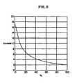
- FIG. 5is a graph that describes a relationship between percentage saline boiling (%) and saline flow rate (Q, in cc/min) for an exemplary RF generator output setting of 75 watts;
- FIG. 6is a schematic graph that describes a relationship between load impedance (Z, in ohms) and generator output power (P, in watts), for an exemplary RF generator output setting of 75 watts in a bipolar mode;
- FIG. 7is a schematic graph that describes a relationship between time (t, in seconds) and tissue impedance (Z, in ohms) after RF activation;
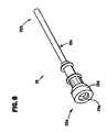
- FIG. 8is a schematic perspective view of a cannula which may be used with an electrosurgical device according to the present invention.
- FIG. 9is a schematic exploded perspective view of an assembly of an electrosurgical device according to the present invention.
- FIG. 10is a schematic longitudinal cross-sectional side view of the tip and shaft of the device of FIG. 9 taken along line 10 - 10 of FIG. 12 ;
- FIG. 11is a schematic close-up longitudinal cross-sectional side view of the tip portion of the device bounded by circle 45 shown in FIG. 10 taken along line 10 - 10 of FIG. 12 ;
- FIG. 12is a schematic distal end view of the tip portion of the device bounded by circle 45 shown in FIG. 10 ;
- FIG. 13is a schematic side view of the of the tip and shaft of the device of FIG. 9 with a fluid coupling to a tissue surface of tissue;
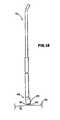
- FIG. 14is a schematic close-up side view of an alternative tip portion
- FIG. 16is a schematic close-up cross-sectional side view of the tip portion of FIG. 14 disposed in a tissue crevice;
- FIG. 17is a schematic graph that describes a relationship between time (t, in seconds) and changes in impedance (Z, in ohms) represented by impedance spikes;
- FIG. 18is a schematic graph that describes a relationship between percentage saline boiling (%) and impedance (Z, in ohms);
- FIG. 19is schematic close-up cross-sectional view of a sleeve taken along line 19 - 19 of FIG. 15 ;
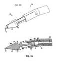
- FIG. 20is a schematic close-up perspective view of an alternative tip portion
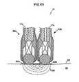
- FIG. 21is a schematic close-up cross-sectional side view of the tip portion of FIG. 20 taken along line 21 - 21 of FIG. 20 ;
- FIG. 22is a schematic close-up cross-sectional side view of the tip portion of FIG. 20 disposed in a tissue crevice;
- FIG. 23is a schematic close-up front perspective view of the electrode for the tip portion of FIG. 20 ;
- FIG. 24is a schematic close-up rear perspective view of the electrode for the tip portion of FIG. 20 ;
- FIG. 25is a schematic close up cross-sectional view of a porous electrode with recesses
- FIG. 26is schematic close up cross-sectional view of an electrode with semi-circular recesses
- FIG. 27is schematic close up cross-sectional view of an electrode with V-shaped recesses
- FIG. 28is schematic close up cross-sectional view of an electrode with U-shaped recesses
- FIG. 29is a schematic close-up perspective view of an alternative tip portion
- FIG. 30is a schematic close-up cross-sectional side view of the tip portion of FIG. 29 taken along line 30 - 30 of FIG. 29 ;
- FIG. 31is a schematic close-up perspective view of an alternative tip portion
- FIG. 32is a schematic close-up cross-sectional side view of the tip portion of FIG. 31 taken along line 32 - 32 of FIG. 31 ;
- FIG. 33is a schematic close-up perspective view of an alternative tip portion
- FIG. 34is a schematic close-up cross-sectional side view of the tip portion of FIG. 33 taken along line 34 - 34 of FIG. 33 ;
- FIG. 35is a schematic close-up perspective view of an alternative tip portion
- FIG. 36is a schematic close-up cross-sectional side view of the tip portion of FIG. 35 taken along line 36 - 36 of FIG. 35 ;
- FIG. 37is a schematic close up side view of an alternative cone shape portion of an electrode
- FIG. 38is a schematic close up side view of an alternative cone shape portion of an electrode
- FIG. 39is a schematic close up side view of an alternative cone shape portion of an electrode
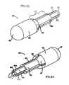
- FIG. 41is a schematic exploded perspective view of an assembly of an alternative electrosurgical device according to the present invention.
- FIG. 42is a schematic close-up cross-sectional side view of the tip portions of FIG. 41 assembled with a fluid coupling to a tissue surface of tissue;
- FIG. 43is a schematic close-up cross-sectional side view of the tip portions of FIG. 41 assembled with an alternative fluid coupling to a tissue surface of tissue;
- FIG. 44is a block diagram showing another embodiment of a control system of the invention, and an electrosurgical device
- FIG. 45is a block diagram of an electrical configuration for a generator and a bipolar device without a hand switch
- FIG. 46is a block diagram of an electrical configuration for a generator and a monopolar device with a hand switch
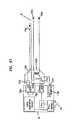
- FIG. 47is a block diagram of an electrical configuration for a generator and a bipolar device with a hand switch and a transformer;
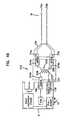
- FIG. 48is a block diagram of an electrical configuration for a generator and a bipolar device without a handswitch and with a transformer;
- FIG. 49is a block diagram of an electrical configuration for a generator, a bipolar device without a hand switch, and an adaptor with a transformer therebetween;
- FIG. 50is a block diagram of an electrical configuration for a generator and a bipolar device with a hand switch
- FIG. 51Ais a block diagram of an electrical configuration for a generator, a bipolar device with a hand switch, and an adaptor with a transformer therebetween;
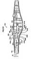
- FIG. 52is a schematic perspective view of an alternative electrosurgical device according to the present invention.
- FIG. 53is a schematic perspective view of a handle portion of the device of FIG. 52 assembled with various components;
- FIG. 54is a schematic side view of a handle portion of the device of FIG. 52 assembled with various components;
- FIG. 55is a schematic side view of a handle portion of the device of FIG. 52 assembled with various components
- FIG. 56is a schematic side view of a handle portion of the device of FIG. 52 assembled with various components
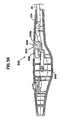
- FIG. 58is a schematic perspective view of a handle portion of the device of FIG. 57 assembled with various components.
- FIG. 59is a schematic side view of a handle portion of the device of FIG. 52 assembled with various components.
- the inventionprovides devices, systems and methods that control tissue temperature at a tissue treatment site during a medical procedure. This is particularly useful during surgical procedures upon tissues of the body, where it is desirable to seal, coagulate and shrink tissue, to occlude lumens of blood vessels (e.g., arteries, veins), airways (e.g., bronchi, bronchioles), bile ducts and lymphatic ducts.
- blood vesselse.g., arteries, veins
- airwayse.g., bronchi, bronchioles
- bile ductse.g., bile ducts
- lymphatic ductse.g., lymphatic ducts.
- the inventionincludes electrosurgical procedures, which preferably utilize RF power and electrically conductive fluid, to treat tissue.
- a desired tissue temperature rangeis achieved by adjusting parameters, such as fluid flow rate, to affect the temperature at the tissue/electrode interface.
- the inventionprovides a control device, the device comprising a flow rate controller that receives a signal indicating power applied to the system, and adjusts the flow rate of fluid from a fluid source to the electrosurgical device.
- the inventionalso provides a control system comprising a flow rate controller, a measurement device that measures power applied to the system, and a pump that provides fluid at a selected flow rate.
- an electrically conductive fluid 24is provided from a fluid source 1 through a fluid line 2 to a pump 3 , which has an outlet fluid line 4 a that is connected as an input fluid line 4 b to electrosurgical device 5 .
- outlet fluid line 4 a and input fluid line 4 bare flexible and are made from a polymeric material, such as polyvinylchloride (PVC) or polyolefin (e.g., polypropylene, polyethylene) and the conductive fluid comprises a saline solution.
- PVCpolyvinylchloride
- polyolefine.g., polypropylene, polyethylene
- the salinecomprises sterile, and even more preferably, normal saline.
- salineas the fluid 24
- other electrically conductive fluids, as well as non-conductive fluidscan be used in accordance with the invention.
- the conductive fluidmay comprise hypertonic saline solution, hypotonic saline solution, Ringers solution (a physiologic solution of distilled water containing specified amounts of sodium chloride, calcium chloride, and potassium chloride), lactated Ringer's solution (a crystalloid electrolyte sterile solution of distilled water containing specified amounts of calcium chloride, potassium chloride, sodium chloride, and sodium lactate), Locke-Ringer's solution (a buffered isotonic solution of distilled water containing specified amounts of sodium chloride, potassium chloride, calcium chloride, sodium bicarbonate, magnesium chloride, and dextrose), or any other electrolyte solution.
- hypertonic saline solutionalso known as “normal” saline, isotonic saline or 0.9% sodium chloride (NaCl) solution
- Ringers solutiona physiologic solution of distilled water containing specified amounts of sodium chloride, calcium chloride, and potassium chloride
- lactated Ringer's solutiona crystalloid electroly
- fluid 24may also comprise an electrically non-conductive fluid.
- a non-conductive fluidis less preferred than a conductive fluid, however, the use of a non-conductive fluid still provides certain advantages over the use of a dry electrode including, for example, reduced occurrence of tissue sticking to the electrode of device 5 and cooling of the electrode and/or tissue. Therefore, it is also within the scope of the invention to include the use of a non-conducting fluid, such as, for example, deionized water.
- energy to heat tissueis provided from an energy source, such as an electrical generator 6 which preferably provides RF alternating current via a cable 7 to an energy source output measurement device, such as a power measurement device 8 that measures the RF alternating current electrical power.
- an energy sourcesuch as an electrical generator 6 which preferably provides RF alternating current via a cable 7 to an energy source output measurement device, such as a power measurement device 8 that measures the RF alternating current electrical power.
- the power measurement device 8does not turn the power off or on, or alter the power in any way.
- a power switch 15 connected to generator 6is preferably provided by the generator manufacturer and is used to turn generator 6 on and off.
- the power switch 15can comprise any switch to turn the power on and off, and is commonly provided in the form of a footswitch or other easily operated switch, such as a switch 15 a mounted on electrosurgical device 5 .
- the power switch 15 or 15 amay also function as a manually activated device for increasing or decreasing the power provided from device 5 .
- internal circuitry and other components of generator 6may be used for automatically increasing or decreasing the power provided from device 5 .
- a cable 9preferably provides RF power from power measurement device 8 to electrosurgical device 5 . Power, or any other energy source output, is preferably measured before it reaches electrosurgical device 5 .
- power Por the rate of energy delivery (e.g., joules/sec)
- I ⁇ Vcurrent times voltage
- I 2 ⁇ Rcurrent squared times resistance
- V 2 /Rvoltage squared divided by the resistance
- the current Imay be measured in amperes
- the voltage Vmay be measured in volts
- the electrical resistance Rmay be measured in ohms
- the power Pmay be measured in watts (joules/sec).
- Heating of the tissueis preferably performed by electrical resistance heating. That is, the temperature of the tissue increases as a result of electric current flow through the tissue, with the electrical energy being absorbed from the voltage and transformed into thermal energy (i.e., heat) via accelerated movement of ions as a function of the tissue's electrical resistance.
- a flow rate controller 11preferably includes a selection switch 12 that can be set to achieve desired levels of percentage fluid boiling (for example, 100%, 98%, 80% boiling).
- flow rate controller 11receives an input signal 10 from power measurement device 3 and calculates an appropriate mathematically predetermined fluid flow rate based on percentage boiling indicated by the selection switch 12 .
- a fluid switch 13is provided so that the fluid system can be primed (e.g., air eliminated) before turning on generator 6 .
- the output signal 16 of flow rate controller 11is preferably sent to pump 3 motor to regulate the flow rate of fluid, and thereby provide an appropriate fluid flow rate which corresponds to the amount of power being delivered.
- flow rate controller 11is configured and arranged to be connected to a source of RF power (e.g., generator 6 ), and a source of fluid (e.g., fluid source 1 ), for example, a source of conductive fluid.
- the device of the inventionreceives information about the level of RF power applied to electrosurgical device 5 , and adjusts the flow rate of fluid 24 to electrosurgical device 5 , thereby controlling temperature at the tissue treatment site.
- elements of the systemare physically included together in one electronic enclosure.
- One such embodimentis shown by enclosure within the outline box 14 of FIG. 1 .
- pump 3 , flow rate controller 11 , and power measurement device 8are enclosed within an enclosure, and these elements are connected through electrical connections to allow signal 10 to pass from power measurement device 8 to flow rate controller 11 , and signal 16 to pass from flow rate controller 11 to pump 3 .
- Other elements of a systemcan also be included within one enclosure, depending upon such factors as the desired application of the system, and the requirements of the user.
- Pump 3can be any suitable pump to provide saline or other fluid at a desired flow rate.
- pump 3is a peristaltic pump.
- a fluid 24is conveyed within the confines of a flexible tube (e.g., 4 a ) by waves of contraction placed externally on the tube which are produced mechanically, typically by rotating rollers which intermittently squeeze the flexible tubing against a support with a linear peristaltic pump, typically a fluid 24 is conveyed within the confines of a flexible tube by waves of contraction placed externally on the tube which are produced mechanically, typically by a series of compression fingers or pads which sequentially squeeze the flexible tubing against a support.
- Peristaltic pumpsare generally preferred, as the electromechanical force mechanism (e.g., rollers driven by electric motor) does not make contact the fluid 24 , thus reducing the likelihood of inadvertent contamination.
- pump 3may include other types of infusion and withdrawal pumps.
- pump 3may comprise pumps which may be categorized as syringe pumps, piston pumps, rotary vane pumps (e.g., axial impeller, centrifugal impeller), cartridge pumps and diaphragm pumps.
- pump 3can be substituted with any type of flow controller, such as a manual roller clamp used in conjunction with an IV bag, or combined with the flow controller to allow the user to control the flow rate of conductive fluid to the device.
- a valve configurationcan be substituted for pump 3 .
- Fluid 24such as conductive fluid, is preferably provided from an intravenous (IV) bag full of saline (e.g., fluid source 1 ) that flows by gravity. Fluid 24 may flow directly to electrosurgical device 5 , or first to pump 3 located there between.
- fluid 24 from a fluid source 1such as an IV bag can be provided through an IV flow controller that may provide a desired flow rate by adjusting the cross sectional area of a flow orifice (e.g., lumen of the connective tubing with the electrosurgical device 5 ) while sensing the flow rate with a sensor such as an optical drop counter.
- fluid 24 from a fluid source 1can be provided through a manually or automatically activated device such as a flow controller, such as a roller clamp, which also adjusts the cross sectional area of a flow orifice and may be adjusted manually by, for example, the user of the device in response to their visual observation (e.g., fluid boiling) at the tissue treatment site or a pump.
- a manually or automatically activated devicesuch as a flow controller, such as a roller clamp, which also adjusts the cross sectional area of a flow orifice and may be adjusted manually by, for example, the user of the device in response to their visual observation (e.g., fluid boiling) at the tissue treatment site or a pump.
- fluid source 1may be a compartment of the electrosurgical device 5 which contains fluid 24 , as indicated at reference character 1 a .
- the compartmentmay be detachably connected to electrosurgical device 5 , such as a canister which may be attached via threaded engagement with device 5 .
- the compartmentmay be configured to hold a pre-filled cartridge of fluid 24 , rather than the fluid directly.
- an energy sourcesuch as a direct current (DC) battery used in conjunction with inverter circuitry and a transformer to produce alternating current at a particular frequency, may comprise a portion of the electrosurgical device 5 , as indicated at reference character 6 a .
- the battery element of the energy sourcemay comprise a rechargeable battery.
- the battery elementmay be detachably connected to the electrosurgical device 5 , such as for recharging.
- distal and proximalare made in reference from the user of the device, and not the patient.
- Flow rate controller 11controls the rate of flow from the fluid source 1 .
- the rate of fluid flow from fluid source 1is based upon the amount of RF power provided from generator 6 to electrosurgical device 5 .
- FIG. 2there is illustrated a relationship between the rate of fluid flow Q and the RF power P. More precisely, as shown in FIG. 2 , the relationship between the rate of fluid flow Q and RF power P may be expressed as a direct, linear relationship.
- the flow rate Q of conductive fluid 24such as saline, interacts with the RF power P and various modes of heat transfer to transfer heat away from the target tissue, as described herein.
- boiling point of salinewhen the terms “boiling point of saline”, “vaporization point of saline”, and variations thereof are used, what is actually referenced for explanation purposes, is the boiling point of the water (i.e., 100° C.) in the saline solution given that the difference between the boiling point of normal saline (about 100.16° C.) and the boiling point of water is negligible.
- FIG. 2shows the relationship between the flow rate of saline, RF power to tissue, and regimes of boiling as detailed below.
- the peak tissue temperaturecan be estimated, and once tissue temperature is estimated, it follows directly whether it is hot enough to boil saline.
- RF power to tissueis represented on the X-axis as P (watts) and flow rate of saline (cc/min) is represented on the Y-axis as Q.
- Pwatts
- Qflow rate of saline
- Qflow rate of saline
- This offsetis the heat conducted to adjacent tissue. For example, using the calculation above for bipolar forceps, this offset RF power is about 10.5 watts. If the power is increased above this level with no saline flow, the peak tissue temperature can rise well above 100° C., resulting in tissue desiccation from the boiling off of water in the cells of the tissue.
- This equationdefines the line shown in FIG. 2 as the line of onset of boiling 76 .
- the most significant factor contributing to heat transfer from a wet electrode devicecan be fractional boiling. The present invention recognizes this fact and exploits it.
- tissue desiccationwhich occurs if the tissue temperature exceeds 100° C. and all the intracellular water boils away, is particularly undesirable as it leaves the tissue extremely dry and much less electrically conductive.
- one control strategy or mechanism which can be employed for the electrosurgical device 5is to adjust the power P and flow rate Q such that the power P used at a corresponding flow rate Q is equal to or less than the power P required to boil 100% of the fluid, and does not exceed the power P required to boil 100% of the fluid.
- Another control strategy that can be used for the electrosurgical device 5is to operate device 5 in the region T ⁇ 100° C., but at high enough temperature to shrink tissue containing Type I collagen (e.g., walls of blood vessels, bronchi, bile ducts, etc.), which shrinks when exposed to about 85° C. for an exposure time of 0.01 seconds, or when exposed to about 65° C. for an exposure time of 15 minutes.
- An exemplary target temperature/time for tissue shrinkageis about 75° C. with an exposure time of about 1 second.
- a determination of the high end of the scalei.e., when the fluid reaches 100° C.
- a determination at the low end of the scalee.g., when the fluid reaches, for example, 75° C. for 1 second) requires a different mechanism as the temperature of the fluid is below the boiling temperature and no such phase change is apparent.
- thermochromic materialsuch as a thermochromic dye (e.g., leuco dye)
- a thermochromic dyee.g., leuco dye
- the dyecan be formulated to provide a first predetermined color to the fluid at temperatures below a threshold temperature, such as 75° C., then, upon heating above 75° C., the dye provides a second color, such as clear, thus turning the fluid clear (i.e., no color or reduction in color). This color change may be gradual, incremental, or instant.
- a change in the color of the fluidprovides a visual indication to the user of the electrosurgical device 5 as to when a threshold fluid temperature below boiling has been achieved.
- Thermochromic dyesare available, for example, from Color Change Corporation, 1740 Cortland Court, Unit A, Addison, Ill. 60101.
- the above mechanismi.e., a change in the color of the fluid due to a dye
- An exemplary target temperature/time for tissue necrosisis about 55° C. for an exposure time of about 1 second.
- control strategy which may be employed for the electrosurgical device 5is to adjust the power P and flow rate Q such that the power P used at a corresponding flow rate Q is equal to or more than the power P required to initiate boiling of the fluid, but still less than the power P required to boil 100% of the fluid.
- this control strategytargets using the electrosurgical device 5 on or between the lines of the onset of boiling 76 and 100% boiling line 80 , and not using the electrosurgical device 5 in the regions of FIG. 2 identified as T ⁇ 100° C. and T>>100° C.
- saline flow rateit is desirable to control the saline flow rate so that it is always on a “line of constant % boiling” as, for example, the line of the onset of boiling 76 or the 100% boiling line 80 or any line of constant % boiling located in between (e.g., 50% boiling line 78 ) as shown in FIG. 2 .
- another control strategy that can be used for the electrosurgical device 5is to adjust power P and flow rate Q such that the power P used at a corresponding flow rate Q targets a line of constant % boiling.
- boiling of the fluidis not detected, such indicates that the temperature is less than 100° C. as shown by the area T ⁇ 100° C. of FIG. 2 , and the flow rate Q must be decreased to initiate boiling if the power remains unchanged.
- the flow rate Qmay be decreased until boiling of the fluid is first detected, at which time the line of the onset of boiling 76 is transgressed and the point of transgression on the line 76 is determined. From the determination of a point on the line of the onset of boiling 76 for a particular power P and flow rate Q, and the known slope of the line 76 as outlined above (i.e., 1/ ⁇ c p ⁇ T), it is also possible to determine the heat conducted to adjacent tissue 70 .
- the flow rate Qmust be increased to reduce boiling until boiling stops, at which time the line of the onset of boiling 76 is transgressed and the point of transgression on the line 76 determined.
- phase changei.e., from liquid to vapor or vice-versa
- a sensorwhich preferably senses either an absolute change (e.g., existence or non-existence of boiling with binary response such as yes or no) or a change in a physical quantity or intensity and converts the change into a useful input signal for an information-gathering system.
- the phase change associated with the onset of boilingmay be detected by a pressure sensor, such as a pressure transducer, located on the electrosurgical device 5 .
- the phase change associated with the onset of boilingmay be detected by a temperature sensor, such as a thermistor or thermocouple, located on the electrosurgical device 5 , such as adjacent to the electrode.
- the phase change associated with the onset of boilingmay be detected by a change in the electric properties of the fluid itself. For example, a change in the electrical resistance of the fluid may be detected by an ohm meter; a change in the amperage may be measured by an amp meter; a change in the voltage may be detected by a volt meter; and a change in the power may be determined by a power meter.
- Yet another control strategy which may be employed for the electrosurgical device 5is to eliminate the heat conduction term 70 of equation (1) (i.e., ⁇ T/R). Since the amount of heat conducted away to adjacent tissue can be difficult to precisely predict, as it may vary, for example, by tissue type, it may be preferable, from a control point of view, to assume the worst case situation of zero heat conduction, and provide enough saline so that if necessary, all the RF power could be used to heat up and boil the saline, thus providing that the peak tissue temperature will not go over 100° C. significantly. This is shown in the schematic graph of FIG. 3 .
- the equation of the line for any line of constant % boilingis known.
- the 98% boiling line, 80% boiling line, etc.can be determined in response to a corresponding input from selection switch 12 .
- the input from the selection switchpreferably may comprise any percentage of boiling.
- the percentage of boilingcan be selected in single percent increments (i.e., 100%, 99%, 98%, etc.).
- flow rate controller 11Upon determination of the line of the onset of boiling 76 , the 100% boiling line 80 or any line of constant % boiling there between, it is generally desirable to control the flow rate Q so that it is always on a particular line of constant % boiling for consistent tissue effect. In such a situation, flow rate controller 11 will adjust the flow rate Q of the fluid 24 to reflect changes in power P provided by the generator 6 , as discussed in greater detail below. For such a use flow rate controller 11 may be set in a line of constant boiling mode, upon which the % boiling is then correspondingly selected.
- the saline flow rate Qit is desirable to control the saline flow rate Q so that it is always on a line of constant % boiling for consistent tissue effect.
- the preferred line of constant % boilingmay vary based on the type of electrosurgical device 5 . For example, if with use of the device 5 , shunting through saline is not an issue, then it can be preferable to operate close to or directly on, but not over the line of the onset of boiling, such as 76 a in FIG. 3 . This preferably keeps tissue as hot as possible without causing desiccation.
- the present inventionprovides a method of controlling boiling of fluid, such as a conductive fluid, at the tissue/electrode interface.
- thisprovides a method of treating tissue without use of tissue sensors, such as temperature or impedance sensors.
- the inventioncan control boiling of conductive fluid at the tissue/electrode interface and thereby control tissue temperature without the use of feedback loops.
- ⁇ c ⁇ V ⁇ T/ ⁇ trepresents the heat required to warm the tissue to the peak temperature (T) 68 and where:
- the inclusion of the heat required to warm the tissue to the peak temperature (T) in the control strategyis graphically represented at 68 in FIG. 4 .
- the effects of the heat required to warm the tissue to the peak temperature (T) 68should be taken into account before flow rate Q adjustment being undertaken to detect the location of the line of onset of boiling 76 .
- the flow rate Qshould not be decreased in response to a lack of boiling before at least a quasi-steady state has been achieved as the location of the line of onset of boiling 76 will continue to move during the transitory period.
- FIG. 5is an exemplary graph of flow rate Q versus % boiling for a situation where the RF power P is 75 watts.
- the percent boiling %is represented on the X-axis
- the saline flow rate Q (cc/min)is represented on the Y-axis.
- the most desirable predetermined saline flow rate Qis 2 cc/min.
- flow rate Q versus % boiling at the remaining points of the graftillustrates a non-linear relationship as follows:
- Typical RF generators used in the fieldhave a monopolar power selector switch to 300 watts of power, and on occasion some have been found to be selectable up to 400 watts of power.
- the calculated flow rate Qis 69.7 cc/min and with a corresponding power of 400 watts the calculated flow rate Q is 92.9 cc/min.
- a fluid flow rate Qof about 100 cc/min or less with the present invention is expected to suffice for the vast majority of applications.
- RF power delivery to tissuecan be unpredictable and vary with time, even though the generator has been “set” to a fixed wattage.
- the schematic graph of FIG. 6shows the general trends of the output curve of a typical general-purpose generator, with the output power changing as load impedance Z changes.
- Load impedance Z(in ohms) is represented on the X-axis
- generator output power P(in watts) is represented on the Y-axis.
- the electrosurgical power (RF)is set to 75 watts in a bipolar mode.
- the powerwill remain constant as it was set as long as the impedance Z stays between two cut-offs, low and high, of impedance, that is, for example, between 50 ohms and 300 ohms in the illustrated embodiment.
- the power Pwill decrease, as shown by the low impedance ramp 28 a .
- the power Pwill decrease, as shown by the high impedance ramp 28 b .
- This change in outputis invisible to the user of the generator and not evident when the generator is in use, such as in an operating room.
- FIG. 7shows the general trend of how tissue impedance generally changes with time for saline-enhanced electrosurgery.
- the temperature coefficient of the tissue and saline in the cellsis such that the tissue impedance decreases until a steady-state temperature is reached upon which time the impedance remains constant.
- the load impedance Zdecreases, potentially approaching the impedance Z cut-off of 50 ohms. If tissue is sufficiently heated, such that the low impedance cut-off is passed, the power P decreases along the lines of the low impedance ramp 28 a of FIG. 6 .
- the control devicereceives a signal indicating the drop in actual power delivered to the tissue and adjusts the flow rate Q of saline to maintain the tissue/electrode interface at a desired temperature.
- the drop in actual power P deliveredis sensed by the power measurement device 8 (shown in FIG. 1 ), and the flow rate Q of saline is decreased by flow rate controller 11 (also shown in FIG. 1 ).
- this reduction in saline flow rate Qallows the tissue temperature to stay as hot as possible without desiccation. If the control device was not in operation and the flow rate Q allowed to remain higher, the tissue would be over-cooled at the lower power input. This would result in decreasing the temperature of the tissue at the treatment site and lead to longer treatment time.
- Flow rate controller 11 of FIG. 1can include a delay mechanism, such as a timer, to automatically keep the saline flow on for several seconds after the RF is turned off to provide a post-coagulation cooling of the tissue or “quench,” which can increase the strength of the tissue seal.
- Flow rate controller 11can also include a delay mechanism, such as a timer, to automatically turn on the saline flow several seconds before the RF is turned on to inhibit the possibility of undesirable effects as tissue desiccation, electrode sticking, char formation and smoke production.
- flow rate controller 11can include a low level flow standby mechanism, such as a valve, which continues the saline flow at a standby flow level (which prevents the flow rate from going to zero when the RF power is turned off) below the surgical flow level ordinarily encountered during use of the electrosurgical device 5 .
- a low level flow standby mechanismsuch as a valve, which continues the saline flow at a standby flow level (which prevents the flow rate from going to zero when the RF power is turned off) below the surgical flow level ordinarily encountered during use of the electrosurgical device 5 .
- FIG. 9An exemplary electrosurgical device of the present invention which may be used in conjunction with the system of the present invention is shown at reference character 5 a in FIG. 9 , and more particularly in FIGS. 9-13 . While various electrosurgical devices of the present invention are described with reference to use with the remainder of the system of the invention, it should be understood that the description of the combination is for purposes of illustrating the remainder of the system of the invention only. Consequently, it should be understood that the electrosurgical devices of the present invention can be used alone, or in conjunction with the remainder of the system of the invention, or that a wide variety of electrosurgical devices can be used in connection with the remainder of the system of the invention.
- the electrosurgical devices disclosed hereinare preferably further configured for both open and minimally invasive surgery, such as laparoscopic surgery. For laparoscopic surgery, the devices are preferably configured to fit through either a 5 mm or 12 mm trocar cannula.
- electrosurgical device 5 amay be used in conjunction with a cannula as illustrated at reference character 19 , during laparoscopic surgery such as, for example, a laparoscopic cholecystectomy.
- Cannula 19comprises a proximal portion 19 a separated from a distal portion 19 b by an elongated rigid shaft portion 19 c .
- Proximal portion 19 a of cannula 19preferably comprises a head portion 19 d connected to rigid shaft portion 19 c , preferably by threaded engagement.
- cannula 19has a working channel 19 e which extends through head portion 19 d and shaft portion 19 c from proximal portion 19 a to distal portion 19 b of cannula 19 .
- electrosurgical device 5 ais configured to enter the proximal end of working channel 19 e , move along the channel 19 e distally, and then be extended from the distal end of the working channel 19 e .
- electrosurgical device 5 ais configured to enter the distal end of working channel 19 e , move along the channel 19 e proximally, and then be removed from the proximal end of working channel 19 e.
- Electrosurgical device 5 ais a monopolar electrosurgical device.
- Electrosurgical device 5 apreferably includes a rigid, self -supporting, hollow shaft 17 , a proximal handle comprising mating handle portions 20 a , 20 b and a tip portion as shown by circle 45 .
- Handle 20 a , 20 bis preferably made of a sterilizable, rigid, non-conductive material, such as a polymer (e.g., polycarbonate).
- tip portion 45includes a contact element preferably comprising an electrode 25 which, as shown, comprises a solid ball having a smooth, uninterrupted surface.
- Tip portion 45also comprises a sleeve 82 having a uniform diameter along its longitudinal length, a spring 88 and a distal portion of shaft 17 .
- the longitudinal axis 31 of the tip portion 45may be configured at an angle A relative to the longitudinal axis 29 of the proximal remainder of shaft 17 .
- angle Ais about 5 degrees to 90 degrees, and more preferably, angle A is about 8 degrees to 45 degrees.
- electrode 25generally has a spherical shape with a corresponding spherical surface, a portion 42 of which is exposed to tissue 32 at the distal end of device 5 a .
- the spheremay have any suitable diameter.
- the spherehas a diameter in the range between and including about 1 mm to about 7 mm, although it has been found that when a sphere is larger than about 4 mm or less than about 2 mm tissue treatment can be adversely effected (particularly tissue treatment time) due to an electrode surface that is respectively either to large or to small.
- the spherehas a diameter in the range between and including about 2.5 mm to about 3.5 mm, more preferably, about 3 mm.
- a distal end surface of electrosurgical device 5 aprovides a blunt, rounded surface which is non-pointed and non-sharp as shown by electrode 25 .
- electrode 25is preferably located in a cavity 81 of a cylindrical sleeve 82 providing a receptacle for electrode 25 .
- sleeve 82guides movement of electrode 25 .
- sleeve 82also functions as a housing for retaining electrode 25 .
- electrode 25is retained within cavity 81 while another portion 43 extends distally through the fluid outlet opening provided by circular fluid exit hole 26 .
- sleeve 82is connected, preferably via welding with silver solder, to the distal end 53 of shaft 17 .
- electrode 25 , sleeve 82 and shaft 17preferably include, and more preferably are made at least almost essentially of, an electrically conductive metal, which is also preferably non-corrosive.
- a preferred materialis stainless steel.
- Other suitable metalsinclude titanium, gold, silver and platinum.
- Shaft 17preferably is stainless steel hypo-tubing.
- cavity 81the internal diameter of cavity 81 surrounding electrode 25 is preferably slightly larger than the diameter of the sphere, typically by about 0.25 mm. This permits the sphere to freely rotate within cavity 81 . Consequently, cavity 81 of sleeve 82 also preferably has a diameter in the range of about 1 mm to about 7 mm.
- the fluid exit hole 26which ultimately provides a fluid outlet opening, of cavity 81 at its distal end 83 comprises a distal pinched region 86 which is reduced to a size smaller than the diameter of electrode 25 , to inhibit escape of electrode 25 from sleeve 82 . More preferably, the fluid exit hole 26 has a diameter smaller than the diameter of electrode 25 .
- fluid exit hole 26preferably has a diameter smaller than the diameter of electrode 25 , which can be accomplished by at least one crimp 84 located at the distal end 83 of sleeve 82 which is directed towards the interior of sleeve 82 and distal to the portion 44 of electrode 25 confined in cavity 81 .
- crimp 84may comprise a single continuous circular rim pattern.
- the contact element portion extending distally through the fluid outlet opening (i.e., electrode portion 43 ) provided by fluid exit hole 26has a complementary shape to the fluid outlet opening provided by fluid exit hole 26 , here both circular.
- crimp 84may have a discontinuous circular rim pattern where crimp 84 is interrupted by at least one rectangular hole slot 85 formed at the distal end 83 of sleeve 82 .
- the fluid outlet opening located at the distal end of the device 5 amay comprise a first portion (e.g., the circular fluid exit hole portion 26 ) and a second portion (e.g., the slot fluid exit hole portion 85 ).
- crimp 84comprises at least four crimp sections forming a circular rim pattern separated by four discrete slots 85 radially located there between at 90 degrees relative to one another and equally positioned around the fluid outlet opening first portion.
- Slots 85are preferably used to provide a fluid outlet opening or exit adjacent electrode 25 , when electrode 25 is fully seated (as discussed below) and/or when electrode 25 is not in use (i.e., not electrically charged) to keep surface portion 42 of the electrode surface of electrode 25 wet.
- slots 85have a width in the range between and including about 0.1 mm to 1 mm, and more preferably about 0.2 mm to 0.3 mm.
- slots 85preferably have a length in the range between and including about 0.1 mm to 1 mm, and more preferably bout 0.4 mm to 0.6 mm.
- the contact element portion extending distally through the fluid outlet openingextends distally through the fluid outlet opening first portion (e.g., the circular fluid exit hole portion 26 ) and does not extend distally through the fluid outlet opening second portion (e.g., the slot fluid exit hole portion 85 ). In this manner an edge 91 of slot 85 remains exposed to tissue 32 to provide a tissue separating edge as discussed below.
- fluid exit hole 26may have an oval shape while electrode 25 has a different shape, such as a round shape.
- At least one edge 91 of slot 85may provide a tissue separating edge adjacent a blunt surface (e.g., surface portion 42 of electrode 25 ) which may be used for blunt dissection when the electrosurgical device 5 a is manipulated, particularly by rotating (e.g., twirling), abrading or impacting.
- a blunt surfacee.g., surface portion 42 of electrode 25
- the edgemay comprise a sharp edge with a sharp angle which has not been rounded by, for example, a fillet.
- proximal end of the tip (comprising electrode 25 , spring 88 and sleeve 82 ) of the device 5 aas shown in FIG. 11 , preferably the portion of sleeve 82 proximal to electrode 25 , also has a proximal pinched region 87 which retains electrode 25 in the cavity 81 of sleeve 82 and inhibits escape of electrode 25 from the cavity 81 of sleeve 82 , such as a diameter smaller than the diameter of electrode 25 .
- distal pinched region 86 and proximal pinched region 87may be used solely to support electrode 25 , in its position of use, the electrode may be further supported by a compression spring 88 as shown in FIG. 11 .
- the use of spring 88is preferred to provide a variable length support within the working length of the spring 88 for overcoming manufacturing tolerances (e.g., length) between the fixed supports (i.e., pinched regions 86 and 87 ) of sleeve 82 .
- sleeve 82also comprises a lumen 89 as shown in FIG. 11 , which, in addition to providing a direct passage for fluid, provides a guide tube for spring 88 .
- the surface portion 60 of electrode 25which contacts spring 88 may have a flat surface rather than a curvilinear surface to better seat the spring against electrode 25 .
- spring 88provides a multitude of functions and advantages.
- the configuration of the distal pinched region 86 , proximal pinched region 87 and spring 88offers the ability to move electrode 25 distally and proximally within sleeve 82 .
- spring 88is located proximal to electrode 25 between a first load bearing surface comprising the electrode surface 60 and a second load bearing surface comprising the distal end 53 of shaft 17 .
- spring 88can be configured to provide a decompression force to seat electrode 25 against the distal pinched region 86 , in this case the perimeter edge 92 of crimp 84 , prior to use of electrosurgical device 5 a.
- the contact element comprising electrode 25is retractable into the cavity 81 of the housing provided by sleeve 82 upon the application of a proximally directed force against surface 42 of the portion 43 of electrode 25 extending distally beyond the distal opening 26 located at the distal end 83 of the housing and spring 88 functions as a retraction biasing member.
- electrosurgical device 5 aBy making electrode 25 positionable in the above manner via spring 88 , electrosurgical device 5 a can be provided with a damper mechanism which dampens the force of electrode 25 on tissue 32 being treated.
- electrode 25which can be positioned as outlined above can comprise a fluid flow rate adjustment mechanism which incrementally increases the area of fluid exit hole 26 and the corresponding fluid flow rate in response to the incremental proximal retraction of electrode 25 .
- electrode 25functions as a valve by regulating flow of fluid 24 through fluid exit hole 26 .
- spring 88may be used in conjunction with the distal pinched region 86 (e.g., crimp 84 comprising a single continuous circular pattern) to provide a fluid seal between electrode 25 and the distal pinched region 86 which stops fluid flow from the electrosurgical device 5 a .
- the electrosurgical device 5 amay be used to provide both a wet electrode and dry electrode (i.e., when the fluid flow is on and off, respectively) with the energy and fluid provided sequentially as opposed to simultaneously.
- an electrode 25which can be positioned as outlined above can include a declogging mechanism. Such a mechanism can retract to provide access for unclogging fluid exit holes (e.g., 26 and 85 ), which may become flow restricted as a result of loose debris (e.g., tissue, blood, coagula) becoming lodged therein.
- unclogging fluid exit holese.g., 26 and 85
- loose debrise.g., tissue, blood, coagula
- a biasing forcesuch as from a handheld cleaning device (e.g., brush) or from pushing the distal tip against a hard surface such as a retractor
- surface 42 of electrode 25which overcomes the compression force of the spring 88 causing the spring 88 to compress and electrode 25 to retract
- the tip of the handheld cleaning devicemay by extended into the fluid exit hole 26 for cleaning the fluid exit hole 26 , perimeter edge 92 , slot 85 and edge 91 .
- electrode 25which can be positioned as outlined, provides a methodology for declogging a fluid exit hole by increasing the cross-sectional area of the fluid exit hole to provide access thereto.
- spring 88comprises an electrical conductor, particularly when electrode 25 , is retracted to a non-contact position (i.e., not in contact) with sleeve 82 .
- proximal pinched region 87may comprise one or more crimps similar to distal pinched region 86 , such that electrode 25 is retained in sleeve 82 both distally and proximally by the crimps.
- sleeve 82may be disposed within shaft 17 rather than being connected to the distal end 53 of shaft 17 .
- sleeve 82may be formed unitarily (i.e., as a single piece or unit) with shaft 17 as a unitary piece.
- electrode 25is retained in sleeve 82 with a portion 43 of electrode 25 extending distally beyond distal end 83 of sleeve 82 .
- the surface 42 of this exposed portion 43 of electrode 25is blunt and does not have any sharp corners.
- the portion 43 of electrode 25 which extends distally beyond the distal end 83 of sleeve 82is controlled by the shape of the fluid exit hole 26 in sleeve 82 in relation to the shape of electrode 25 .
- the portion 43 of electrode 25 that extends distally beyond distal end 83 of sleeve 82is controlled by the contact of the electrode surface with the edge 92 .
- an electrical insulator 90preferably surrounds shaft 17 and sleeve 82 along substantially its entire exposed length (e.g., the portion outside the confines of the handle 20 ), terminating a short distance (e.g., at the proximal onset of crimp 84 or less than about 3 mm) from distal end 83 of sleeve 82 .
- Insulator 90preferably comprises a shrink wrap polymer tubing.
- a input fluid line 4 b and a power source, preferably comprising generator 6 preferably providing RF power via cable 9are preferably fluidly and electrically coupled, respectively, to the tip portion 45 of the electrosurgical device 5 a.
- device 5 acomprises a monopolar device.
- electrode 25provides an active electrode
- a ground pad dispersive electrode 125located on the patient, typically on the back or other suitable anatomical location, provides a return electrode.
- both electrodesare electrically coupled to generator 6 to form an isolated electrical circuit.
- the active electrodeis coupled to generator 6 via a wire conductor from insulated wire cable 9 to the outer surface 18 of shaft 17 within the confines of handle 20 a , 20 b , typically through a switch such as 15 a.
- Switch 15 apreferably comprises a dome switch having two electrical contacts.
- the contactspreferably comprise upper and lower contacts disposed on a platform in overlying relationship.
- the upper contactcomprises a dome shaped configuration overlying and spaced from the lower contact which is flat.
- the contactsare spaced from one another by virtue of the domed configuration of the upper contact when the switch 15 a is in an undepressed position, thus creating an open control circuit relative to switch 15 a .
- the upper contactis pressed into a depressed position, the upper contact comes into contact with the lower contact thus closing the hand switch control circuit.
- the presence of the closed control circuitis then sensed by generator 6 which then provides power to the electrode 25 .
- shaft 17may be made of an electrical non-conducting material except for a portion at its distal end 53 that comes in contact with sleeve 82 . This portion of shaft 17 that contacts sleeve 82 should be electrically conducting. In this embodiment, the wire conductor from insulated wire cable 9 extends to this electrically conducting portion of shaft 17 . In still other embodiments, shaft 17 may completely comprise a non-conducting material as where the wire conductor from insulated wire cable 9 extends directly to sleeve 32 .
- fluid 24 from the fluid source 1preferably is communicated from fluid source 1 through a flexible, polyvinylchloride (PVC) outlet fluid line 4 a to a flexible, polyvinylchloride (PVC) inlet fluid line 4 b connected to electrosurgical device 5 a .
- Outlet fluid line 4 a and inlet fluid line 4 bare preferably connected via a male and female mechanical fastener configuration; a preferred such connection is a Luer-Lok® connection from Becton, Dickinson and Company.
- the lumen of the inlet lineis then preferably interference fit over the outside diameter of shaft 17 to provide a press fit seal there between. An adhesive may be used there between to strengthen the seal.
- Fluid 24is then communicated down lumen 23 of shaft 17 through lumen 89 and cavity 81 of sleeve 82 where it is expelled from around and on the exposed surface 42 of electrode 25 . This provides a wet electrode for performing electrosurgery.
- a fluid coupling 30preferably comprising a discrete, localized web and more preferably comprising a triangular shaped web or bead portion providing a film of fluid 24 is provided between surface 22 of tissue 32 and electrode 25 .
- a fluid coupling 30preferably comprising a discrete, localized web and more preferably comprising a triangular shaped web or bead portion providing a film of fluid 24 is provided between surface 22 of tissue 32 and electrode 25 .
- the fluid 24in addition to providing an electrical coupling between electrosurgical device 5 a and tissue 32 , lubricates surface 22 of tissue 32 and facilitates the movement of electrode 25 across surface 22 of tissue 32 .
- electrode 25typically slides across surface 22 of tissue 32 , but also may rotate as electrode 25 moves across surface 22 of tissue 32 .
- the user of the electrosurgical device 5 aslides the electrode across surface 22 of tissue 32 back and forth with a painting motion while using fluid 24 as, among other things, a lubricating coating.
- the thickness of the fluid 24 between the distal end surface of electrode 25 and surface 22 of tissue 32 at the outer edge of the coupling 30is in the range between and including about 0.05 mm to 1.5 mm, more preferably in the range between and including about 0.1 mm to 0.3 mm. Also preferably, in certain embodiments, the distal end tip of electrode 25 contacts surface 22 of tissue 32 without any fluid 24 in between.
- electrical insulator 90preferably terminates proximally to sleeve 82 where sleeve 82 is connected to the distal end 53 of shaft 17 .
- electrical insulator 90preferably terminates proximally to proximal pinched region 87 .
- a cylindrical surface 40 of a cylindrical portion 39 of sleeve 82 and a broadening surface portion 47 of broadening portion 54here both conical, of sleeve 82 also function as electrode surfaces for treating tissue.
- the electrode exposed to tissue 32now comprises a cylindrical surface portion 40 and a broadening surface portion 47 in addition to the spherical surface portion 42 and the narrowing surface portion 41 , with the cylindrical surface portion 40 substantially increasing the surface area of the electrode.
- electrode 25has surfaces which are parallel and perpendicular to the longitudinal axis 31 of tip portion 45 , and more particularly, sleeve 82 of electrosurgical device 5 b .
- front end usee.g., surfaces 41 and 42
- sideways usee.g., surface 40 and 47
- oblique usee.g., surfaces 40 , 41 and 42
- tip portion 45now includes a first tissue treating surface (e.g., distal end spherical surface 42 ) and a second tissue treating surface (e.g., side surface 40 ).
- first tissue treating surfacee.g., distal end spherical surface 42
- second tissue treating surfacee.g., side surface 40
- first tissue treating surfaceis configured for blunt dissection while the second tissue treating surface is configured for coagulation.
- tip portion 45also has a third tissue treating surface (e.g., surface 41 ) located between the first tissue treating surface (e.g., surface 42 ) and a second tissue treating surface (e.g., surface 40 ).
- tip portion 45also has a fourth tissue treating surface (e.g., surface 47 ) located proximal and adjacent to surface 40 .
- tissue 32may occlude fluid flow from fluid exit holes 26 , 85 located at the distal end of device 5 a . Consequently, for device 5 b fluid exit holes 93 , 94 may be located in the cylindrical side portion 39 of sleeve 82 , either proximal or adjacent to electrode 25 , and either in addition to or as an alternative to fluid exit holes 26 , 85 .
- At least one fluid exit hole 93is preferably formed in the cylindrical longitudinal side surface 40 and through the wall of side portion 39 of sleeve 82 adjacent to electrode 25 when electrode 25 is fully seated. Furthermore, preferably at least one fluid exit hole 94 is formed in the cylindrical side portion 39 of sleeve 82 proximal to electrode 25 when electrode 25 is fully seated.
- holes 93 , 94each has more than one hole which are equally spaced radially in a circular pattern around the longitudinal axis 31 of tip portion 45 , and more particularly sleeve 82 . More preferably, holes 93 , 94 each comprise four discrete holes equally spaced 90 degrees around the cylindrical side portion 39 of sleeve 82 . Preferably holes 93 , 94 have a diameter in the range between and including about 0.1 mm to 1.0 mm, and more preferably have a length in the range between and including about 0.2 mm to 0.6 mm.
- Electrode 25which can be positioned as outlined above, can comprise not only a valve for regulating fluid flow from the fluid exit holes, such as fluid exit hole 26 , but also comprise a valve which, while opening one fluid flow exit, simultaneously closes another fluid flow exit. For example, as electrode 25 retracts proximally, fluid exit hole 26 is opened while fluid exit hole 93 is closed. Stated another way, an electrode 25 which can be positioned as outlined above can provide a mechanism for altering the size and/or location of the fluid exit holes during use of electrosurgical device 5 b which may be necessary, for example, to direct fluid to a particular tissue location or balance fluid flow among the fluid exit outlets.
- surfaces 40 , 41 and 47 of sleeve 82 , and surface 42 of electrode 25are all active electrode surfaces and can provide electrical energy to tissue 32 . Portions of this combined electrode surface can be wet by fluid flow from holes 26 , 94 or 93 , as well as from the hole slots 85 in crimp 84 adjacent electrode 25 .
- the holes 94 , 93 in the cylindrical sleeve 82 of the overall electrode surfaceare intended to assure that fluid 24 is provided to the smooth, less rough, atraumatic sides of the electrode that may be predominately used for tissue coagulation and hemostasis (e.g., surfaces 40 and 47 ) rather than blunt dissection (e.g., surfaces 41 and 42 ).
- the most distal portion of the devicemay have a more rough, but also wetted, electrode surface that can blunt dissect as well as coagulate tissue.
- the electrode configuration shown in FIGS. 14 and 15is particularly useful to a surgeon performing a liver resection.
- the distal tip of tip portion 45is painted back and forth along the line, resulting in coagulation of the liver parenchyma beneath the scored capsule.
- the electrodeis used to blunt dissect into the coagulated parenchyma, with edge 91 of slots 85 around crimp 84 providing roughness elements that aid in disrupting the tissue 32 and enabling the parting of tissue 32 .
- the device 5 bcan be used in a crevice 97 of tissue 32 to blunt dissect tissue 32 and coagulate it at the same time.
- Blunt dissectionis preferred over sharp dissection, such as with a blade or scissors, since blunt dissection is less likely to tear or damage the larger blood vessels or other vessels.
- Once identified by blunt dissectionvery large vessels can be safely clipped, tied with suture or sealed with some other device. If the larger vessels are not thus first “skeletonized” without being damaged by blunt dissection, they may bleed profusely and require much more time to stop the bleeding.
- the devicecan also be used to coagulate first without simultaneous blunt dissection, and then blunt dissect in a separate step.
- This techniquecan also be used on other parenchymal organs such as the pancreas, the kidney, and the lung. In addition, it may also be useful on muscle tissue and subcutaneous fat. Its use can also extend to benign tumors, cysts or other tissue masses found in the urological or gynecological areas. It would also enable the removal of highly vascularized tumors such as hemangiomas.
- fluid outlet openingsare provided by substantially linear through holes 93 , 94 which provide conductive fluid 24 to the treatment site.
- fluid outlet openings in sleeve 82may be provided by holes in the form of tortuous and interconnected pathways 59 , which are formed in a material pervious to the passage of fluid 24 , therethrough, such as a porous material.
- the discrete, linear through holes 93 , 94may be either supplemented with or replaced by a plurality of tortuous, interconnected pathways 59 formed in the porous material which, among other things, provides porous surfaces 40 , 41 and 47 to more evenly distribute fluid flow and provide the conductive fluid 24 to tissue 32 at the treatment site.
- all or a portion of sleeve 82may comprise a material pervious to the passage of fluid 24 therethrough as disclosed herein.
- the contact element, here electrode 25may also comprise a material pervious to the passage of fluid 24 , therethrough, such as a porous material (e.g., metal, polymer or ceramic) to provide the tortuous pathways 59 .
- a porous materiale.g., metal, polymer or ceramic
- the porous structure of electrode 25allows fluid 24 to not only pass around electrode 25 on the outer porous surface 42 to be expelled, but also allows fluid 24 to pass through electrode 25 , to be expelled.
- all or a portion of the electrodes or any particular electrodes for treating tissue 32may comprise a material pervious to the passage of fluid 24 therethrough as disclosed herein.
- the porous materialfurther comprises porous metal.
- Porous sintered metalis available in many materials (such as, for example, 316L stainless steel, titanium, Ni-Chrome) and shapes (such as cylinders, discs, plugs) from companies such as Porvair, located in Henderson, N.C.
- the electrode provided by contact element and/or sleevepreferably comprises an electrically conductive material such as metal
- a non-electrically conductive porous contact element and/or sleevesuch as porous polymers and ceramics
- the porous polymers and ceramicsare generally non-conductive, they may also be used to conduct the RF energy through the porous polymer and ceramic thickness and porous surface to the tissue to be treated by virtue of conductive fluid 24 contained within the plurality of interconnected tortuous pathways 59 .
- the porous materialprovides for the wicking (i.e., drawing in of fluid by capillary action or capillarity) of the fluid 24 into the pores of the porous material.
- the porous materialis hydrophilic.
- the porous materialmay be hydrophilic with or without post treating (e.g., plasma surface treatment such as hypercleaning, etching or micro-roughening, plasma surface modification of the molecular structure, surface chemical activation or crosslinking), or made hydrophilic by a coating provided thereto, such as a surfactant.
- fluid coupling 30 of fluid 24be present in between the metal electrode surfaces (e.g., 40 , 41 , 42 ) and tissue 32 at all locations of tissue treatment and there may be points of direct tissue contact by the electrode surfaces without any fluid coupling 30 therebetween.
- the convective cooling of the metal electrode by flowing salineis often sufficient to keep the metal electrode and tissue contacting the metal electrode at or below a temperature of 100° C.
- heatmay be also first dissipated from tissue 32 to the electrodes by conduction, then dissipated from the electrodes to the fluid 24 by convection.
- the relationship between the material for electrodes particularly their surfaces (e.g., 40 , 41 , 42 , 47 ), and fluid 24 throughout the various embodimentsshould be such that the fluid 24 wets the surface of the electrodes to form a continuous thin film coating thereon (for example, see FIG. 21 ) and does not form isolated rivulets or circular beads (e.g., with a contact angle, ⁇ greater than 90 degrees) which freely run off the surface of the electrode.
- Contact angle, ⁇is a quantitative measure of the wetting of a solid by a liquid. It is defined geometrically as the angle formed by a liquid at the three phase boundary where a liquid, gas and solid intersect.
- contact angle ⁇may be defined by the preceding equation
- contact angle ⁇is determined by various models, to an approximation.
- the five predominate models and their synonymsare: (1) Zisman critical wetting tension; (2) Girifalco, Good, Fowkes, Young combining rule; (3) Owens, Wendt geometric mean; (4) Wu harmonic mean; and (5) Lewis acid/base theory.
- any one of the five predominate models above which calculates a contact angle ⁇ within a particular range of contact angles ⁇ or the contact angle ⁇ required of a particular embodiment of the inventionshould be considered as fulfilling the requirements of the embodiment, even if the remaining four models calculate a contact angle ⁇ which does not fulfill the requirements of the embodiment.
- Bond number N BO1
- the droplet diameteris equal to about 0.273 cm or about 2.7 mm, which is in the same order of magnitude as the preferred size of the electrode.
- Bond number N BO for a droplet of fluid 24 on a surface of electrode 25is preferably less than 1.
- electrode 25preferably is detachably assembled to the shaft 17 such that it may be removed from the shaft 17 , preferably manually by human hand, so that the shaft 17 may be used with multiple different contact elements/electrodes, or the shaft 17 may be reuseable and used with disposable contact elements/electrodes.
- the enlarged head portion of electrode 25preferably also comprises a cylindrical portion 39 and a corresponding cylindrical surface portion 40 located proximal and adjacent to the spherical portion 43 and spherical surface portion 42 , respectively.
- electrode 25preferably comprises a connector portion, preferably comprising a shank 46 , which connects the remainder of electrode 25 to the shaft 17 .
- the connector portion of electrode 25is preferably configured to form a connection with a mating connector portion of the shaft 17 .
- the shank portion 46is configured to extend into cavity 50 of shaft 17 which comprises a cylindrical receptacle and provides the mating connector portion for shank 46 .
- surface 48 of the shank portion 46is configured to mate against and form an interference fit with surface 52 of cavity 50 to provide the connection.
- cylindrical portion 39has a diameter in the range between and including about 1 mm to about 7 mm, although it has been found that when cylindrical portion 39 is larger than about 4 mm or less than about 2 mm, tissue treatment can be adversely effected (particularly tissue treatment time) due to an electrode surface that is respectively either to large or to small.
- the cylindrical portion 39has a diameter in the range between and including about 2.5 mm to about 3.5 mm, and more preferably, about 3 mm.
- cylindrical portion 39has a length in the range between and including about 2 mm to about 8 mm, and more preferably has a length in the range between and including about 3 mm to about 5 mm. Even more preferably, cylindrical portion 39 has a length of about 4.5 mm.
- the cylindrical portion 57 of neck portion 56preferably has a cross-sectional dimension, here diameter, greater than the cross-sectional dimension, here also diameter, of the shank 46 .
- the proximal end of the neck portion 56may be located adjacent and in contact with the distal end 53 of shaft 17 .
- cylindrical portion 57has a diameter in the range between and including about 2 mm to about 2.5 mm and the shank 46 has a diameter in the range between and including about 1.4 mm to about 1.9 mm. More preferably, cylindrical portion 57 has a diameter of about 2.2 mm and the shank 46 has a diameter of about 1.6 mm.
- cylindrical portion 57has a length in the range between and including about 1 mm to about 8 mm, and more preferably has a length in the range between and including about 3 mm to about 5 mm. Even more preferably, cylindrical portion 57 has a length of about 4 mm.
- Shank 46preferably has a length in the range between and including about 2 mm to about 6 mm, and more preferably has a length in the range between and including about 2.5 mm to about 5 mm. Even more preferably, shank 46 has a length of about 3 mm.
- electrode 25comprises at least one recess 64 which provides an elongated fluid flow channel for the distribution of fluid 24 .
- the use of device 5 c , and in particular recesses 64 , for the distribution of fluid 24is generally preferred to the fluid exit holes 93 , 94 of device 5 b in particularly deep tissue crevices 97 .
- the recess 64may be occluded by tissue 32 completely along its longitudinal length, thus completely inhibiting fluid flow from exiting through opening 55 .
- at least a portion of electrode 25may comprise a material pervious to the passage of fluid 24 , therethrough, such as a porous material described above.
- device 5 chas been found to be particularly useful to a surgeon performing a liver resection.
- the distal tip of tip portion 45is painted back and forth along the line, with radio frequency power and the flow of fluid 24 on, resulting in coagulation of the liver parenchyma.
- surfaces 40 and 42 of electrode 25are used to blunt dissect the coagulated parenchyma.
- Blunt dissection of the coagulated parenchymais performed by continuous abrading or splitting apart of the parenchyma with the substantially the same back and forth motion as coagulation and with the device 5 c being held substantially in the same orientation as for coagulation of the liver parenchyma.
- blunt dissectionthe surgeon typically applies more force to the tissue.
- blunt dissectionmay be performed with or without the radio frequency power (i.e., on or off) and/or with or without the presence of fluid 24 .
- the walls 64 a , 64 b of recess 64 , surface 48 of the shank portion 46 , and/or the surfaces of the neck portion 56 of electrode 25may be porous and connected by a plurality of tortuous pathways 59 in the porous material.
- electrode 25comprises a porous material
- recess 64may be either supplemented with or replaced by the plurality of tortuous, interconnected passages 59 formed in the porous material as shown in FIG. 25 . All or a portion of the electrodes can be porous according to the invention.
- recess 64may comprise cross-sectional shapes other than rectangular shapes.
- recess 64comprises a semi-circular shape, a V-shape, or a U-shape respectively, or any combination thereof.
- recesses 64 of device 5 care initiated within the confines of shaft 17 .
- the use of device 5 c , and in particular recesses 64 , for the distribution of fluid 24is generally preferred to the fluid exit holes 93 , 94 of device 5 b in deep tissue crevices 97 where tissue 32 can occlude fluid flow from the fluid exit holes 93 , 94 located in the cylindrical portion 39 of electrode 25 .
- holes 93 , 94are not presented with a declogging mechanism, such as provided for such as fluid exit holes 26 and 85 , holes such as 93 , 94 that can be simply occluded by ordinary tissue/electrode contact will sooner or later become irreversibly clogged.
- fluid outlet openings 73are provided by the structure of electrode 25 (i.e., recesses 64 ) at the distal end 53 of the shaft 17 which are protected and sheltered from contact and occlusion from surface 22 of tissue 32 .
- Fluid outlet openings 73 of device 5 care protected from occlusion from surface 22 of tissue 32 as the structure of device 5 c defining the openings 26 is at least partially configured for non-contact with surface 22 of tissue 32 . More specifically, here the structure of the device defining the openings 73 is completely configured for non-contact with surface 22 of tissue 32 . Stated another way, the openings 73 are provided on the device 5 c at a location removed from the tissue surface 22 .
- openings 26are particularly sheltered from occlusion from surface by 22 of tissue 32 by a portion of the shaft 17 .
- openings 73are formed substantially perpendicular to the surface 22 of tissue 32 and thus turned away from direct contact with surface 22 of tissue 32 .
- FIGS. 29-30Another tip portion of an exemplary electrosurgical device 5 e of the present invention which may be used in conjunction with the system of the present invention is shown at reference character 45 in FIGS. 29-30 .
- the broadening portion 54has been eliminated and the cylindrical portion 39 has an equal cross-sectional dimension, here diameter, with the neck portion 56 .
- the cylindrical portion 39has a cross-sectional dimension, there also diameter, greater than the cross-sectional dimension, there also diameter, of the neck portion 56 .
- the cylindrical portion 39further comprises a rectilinear cylindrical portion 39 a having a rectilinear cylindrical surface portion 40 a and a curvilinear cylindrical portion 39 b having a curvilinear cylindrical surface portion 40 b .
- device 5 ecomprises the shape of a hockey stick.
- the cylindrical portion 39 for device 5 cmay be similarly arranged.
- FIGS. 31-32Another tip portion of an exemplary electrosurgical device 5 f of the present invention which may be used in conjunction with the system of the present invention is shown at reference character 45 in FIGS. 31-32 .
- the cylindrical portion 39has a cross-sectional dimension, here diameter, less than the cross-sectional dimension, here also diameter, of the neck portion 56 .
- the neck portion 56includes a narrowing portion 49 with a corresponding narrowing surface portion 51 , here both conical.
- the cylindrical portion 39further comprises a rectilinear cylindrical portion 39 a having a rectilinear cylindrical surface portion 40 a and a curvilinear cylindrical portion 39 b having a curvilinear cylindrical surface portion 40 b .
- the cylindrical portion 39and more specifically at least one of the rectilinear cylindrical portion 39 a and the curvilinear cylindrical portion 39 b , comprises a portion of a hook.
- both the rectilinear cylindrical portion 39 a and the curvilinear cylindrical portion 39 bcomprise portions of a hook.
- the hookfurther comprises an L-hook.
- FIGS. 33-34Another tip portion of an exemplary electrosurgical device 5 g of the present invention which may be used in conjunction with the system of the present invention is shown at reference character 45 in FIGS. 33-34 . Similar to devices 5 c - 5 f , the separate sleeve 82 of embodiments 5 a and 5 b has been eliminated from tip portion 45 of device 5 g . Consequently, the contact element, still preferably comprising an electrode 25 , is assembled directly with the shaft 17 . Electrode 25 is preferably assembled (e.g., mechanically connected via a press fit, or interference fit, adjacent the distal end 53 of shaft 17 .
- electrode 25preferably comprises a spherical portion 43 and a corresponding spherical surface portion 42 located at the distal end of the device 5 g , which provided a smooth, blunt contour outer surface. More specifically, as shown, the spherical portion 43 and spherical surface portion 42 further provide a domed, hemisphere (i.e., less than a full sphere) and hemispherical surface portion comprising preferably about 180 degrees.
- electrode 25preferably also comprises a narrowing portion 49 and a corresponding narrowing surface portion 51 , here both conical, located proximal and adjacent to the spherical portion 43 and spherical surface portion 42 , respectively.
- narrowing portion 49 and corresponding narrowing surface portion 51comprise a conical portion in the form of a concentric cone shape, as opposed to device 5 f where the conical portion provided by narrowing portion 49 and a corresponding narrowing surface portion 51 comprises an eccentric cone shape.
- spherical portion 43 and spherical surface portion 42may provide a blunt apex to narrowing portion 49 and a corresponding narrowing surface portion 51 , respectively.
- electrode 25preferably also comprises a cylindrical portion 39 and a corresponding cylindrical surface portion 40 located proximal and adjacent to the narrowing portion 49 and narrowing surface portion 51 , respectively.
- electrode 25preferably comprises a connector portion, preferably comprising a shank 46 , which connects the remainder of electrode 25 to the shaft 17 .
- the connector portion of electrode 25is preferably configured to form a connection with a mating connector portion of the shaft 17 .
- the shank portion 46is configured to extend into cavity 50 of shaft 17 which comprises a cylindrical receptacle and provides the mating connector portion for shank 46 .
- surface 48 of the shank portion 46is configured to mate against and form an interference fit with surface 52 of cavity 50 to provide the connection.
- shank portion 46is preferably cylindrical and located proximal and adjacent to a neck portion 56 .
- neck portion 56comprises a cylindrical portion 57 (having a corresponding cylindrical surface portion 58 ) and a broadening portion 54 (having a corresponding broadening surface portion 47 ).
- broadening portion 54 and corresponding broadening surface portion 47are both spherical, and more specifically comprise a domed, hemisphere and hemispherical surface portion comprising preferably about 180 degrees, located proximal and adjacent to the cylindrical portion 39 and cylindrical surface portion 40 .
- electrode 25comprises at least one recess 64 which provides an elongated fluid flow channel for the distribution of fluid 24 .
- electrode 25preferably comprises a plurality of longitudinally directed recesses 64 and, more specifically, four recesses 64 equally spaced 90 degrees around the shank 46 and/or neck portion 56 , both proximal of cylindrical portion 39 .
- FIGS. 35-36Another tip portion of an exemplary electrosurgical device 5 h of the present invention which may be used in conjunction with the system of the present invention is shown at reference character 45 in FIGS. 35-36 .
- Device 5 his similar to device 5 g in all respects except that spherical portion 43 and spherical surface portion 42 have been eliminated and replaced with a distal end sharp point 71 .
- the electrode 25 of device 5 hcomprises a simple cone.
- electrode 25may comprise other cone shapes.
- the cone shapemay comprise an give cone shape, an elliptical (prolate hemispheroid) cone shape, a bi-conic cone shape and parabolic series cone shapes, respectively, which all may be defined by mathematical equations as known in the art.
- Still other cone shapesmay include power series cone shapes, Haake series cone shapes, Sears-Haake and Von Karman, which all may be defined by mathematical equations as known in the art.
- Certain embodiments of the inventionmay be particularly configured for bipolar devices.
- an exemplary bipolar electrosurgical device of the present inventionwhich may be used in conjunction with the system of the present invention is shown at reference character 5 i in FIGS. 41-43 .
- the ground pad electrode located on the patientis eliminated and replaced with a second electrical pole as part of the device.
- An alternating current electrical circuitis then created between the first and second electrical poles of the device. Consequently, alternating current no longer flows through the patient's body to the ground pad electrode, but rather through a localized portion of tissue preferably between the poles of the bipolar device.
- the arms of device 5 i(comprising shafts 17 a , 17 b ) are retained in position relative to each other by a mechanical coupling device comprising a collar 95 and inhibited from separating relative to each other.
- Collar 95preferably comprises a polymer (e.g., acrylonitrile-butadiene-styrene or polycarbonate) and is preferably located on the distal portion of the arms. More preferably, the collar 95 is located proximal the distal ends 53 a , 53 b of the shafts 17 a , 17 b .
- the collar 95comprises two apertures 96 a , 96 b , preferably comprising opposing C-shapes, configured to receive a portion of the shafts 17 a , 17 b which are preferably snap-fit therein.
- the collar 95may be configured to slide along the length of the shafts 17 a , 17 b as to adjust or vary the location of the collar 95 on the shafts 17 a , 17 b .
- the location of the collar 95may be fixed relative to the shafts 17 a , 17 b by welding, for example.
- Electrodes 25 a , 25 bare laterally spaced adjacent tissue surface 22 of tissue 32 . Electrodes 25 a , 25 b are connected to a source of alternating electrical current and alternating current electrical field is created between electrodes 25 a and 25 b . In the presence of alternating current, the electrodes alternate polarity between positive and negative charges with current flow from the positive to negative charge.
- fluid 24is communicated from a fluid source 1 within the lumens 23 a , 23 b of the shafts 17 a , 17 b through the lumens 89 a , 89 b and cavities 81 a , 81 b of the sleeves 82 a , 82 b where it is expelled from around and on the surface 42 a , 42 b of the electrodes 25 a , 25 b.
- fluid couplings 30 a , 30 bpreferably comprising discrete, localized webs and more preferably comprising a triangular shaped web or bead portion providing a film of fluid 24 between surface 22 of tissue 32 and electrodes 25 a , 25 a .
- Electrosurgical device 5When the user of electrosurgical device 5 i places electrodes 25 a , 25 b at a tissue treatment site and moves electrodes 25 a , 25 b across surface 22 of tissue 32 , fluid 24 is expelled around and on surfaces 42 a , 42 b of electrodes 25 a , 25 b at the distal ends 83 a , 83 b of sleeves 82 a , 82 b and onto surface 22 of tissue 32 via couplings 30 a , 30 b .
- RF electrical energyshown by electrical field lines 130 , is provided to tissue 32 at tissue surface 22 and below tissue surface 22 into tissue 32 through fluid couplings 25 a , 25 b.
- the fluid 24in addition to providing an electrical coupling between the electrosurgical device 5 i and tissue 32 , lubricates surface 22 of tissue 32 and facilitates the movement of electrodes 25 a , 25 b across surface 22 of tissue 32 .
- electrodes 25 a , 25 btypically slide across the surface 22 of tissue 32 , but also may rotate as electrodes 25 a , 25 b move across surface 22 of the tissue 32 .
- the user of electrosurgical device 5 islides electrodes 25 a , 25 b across surface 22 of tissue 32 back and forth with a painting motion while using fluid 24 as, among other things, a lubricating coating.
- the thickness of the fluid 24 between the distal end surface of electrodes 25 a , 25 b and surface 22 of tissue 32 at the outer edge of couplings 30 a , 30 bis in the range between and including about 0.05 mm to 1.5 mm. More preferably, fluid 24 between the distal end surface of electrodes 25 a , 25 b and surface 22 of tissue 32 at the outer edge of coupling 30 a , 30 b is in the range between and including about 0.1 mm to 0.3 mm. Also preferably, in certain embodiments, the distal end tip of electrode 25 contacts surface 22 of tissue 32 without any fluid 24 in between.
- the fluid coupling for device 5 imay comprise a conductive fluid bridge 27 between electrodes 25 a , 25 b which rests on surface 22 of tissue 32 and forms a shunt between electrodes 25 a , 25 b .
- a certain amount of RF energymay be diverted from going into tissue 32 and actually pass between electrodes 25 a , 25 b via the conductive fluid bridge 27 . This loss of RF energy may slow down the process of coagulating tissue and producing the desired hemostasis or aerostasis of the tissue.
- the loss of RF energycorrespondingly decreases with the loss of bridge 27 .
- energyis provided into fluid 24 of bridge 27 by means of heat dissipating from tissue 32 .
- one control strategy of the present inventionis to reduce the presence of a conductive fluid shunt by increasing the % boiling of the conductive fluid.
- Bipolar device 5 iis particularly useful as non-coaptive tissue sealer and coagulator given it does not grasp tissue.
- Device 5 iis particularly useful to surgeons to achieve hemostasis after dissecting through soft tissue as part of hip or knee arthroplasty.
- the tissue treating portionscan be painted over the raw, oozing surface 22 of tissue 32 to seal the tissue 32 against bleeding, or focused on individual larger bleeding vessels to stop vessel bleeding.
- Bipolar device 5 iis also useful to stop bleeding from the surface of cut bone tissue as part of any orthopaedic procedure that requires bone to be cut.
- Device 5 iis particularly useful for these applications over monopolar device 5 a as a much greater surface area 22 of tissue 32 may be treated in an equivalent period of time and with better controlled depth of the treatment.
- boneAs is well known, bone, or osseous tissue, is a particular form of dense connective tissue consisting of bone cells (osteocytes) embedded in a matrix of calcified intercellular substance. Bone matrix mainly contains collagen fibers and the minerals calcium carbonate, calcium phosphate and hydroxyapatite. Among the many types of bone within the human body are compact bone and cancellous bone. Compact bone is hard, dense bone that forms the surface layers of bones and also the shafts of long bones. It is primarily made of haversian systems which are covered by the periosteum. Compact bone contains discrete nutrient canals through which blood vessels gain access to the haversian systems and the marrow cavity of long bones.
- Bipolar device 5 i disclosed hereinmay be particularly useful to treat compact bone and to provide hemostasis and seal bleeding vessels (e.g. by shrinking to complete close) and other structures associated with Volkmann's canals and Haversian systems.
- cancellous boneIn contrast to compact bone, cancellous bone is spongy bone and forms the bulk of the short, flat, and irregular bones and the ends of long bones.
- the network of osseous tissue that makes up the cancellous bone structurecomprises many small trabeculae, partially enclosing many intercommunicating spaces filled with bone marrow. Consequently, due to their trabecular structure, cancellous bones are more amorphous than compact bones, and have many more channels with various blood cell precursors mixed with capillaries, venules and arterioles.
- Bipolar device 5 i disclosed hereinmay be particularly useful to treat cancellous bone and to provide hemostasis and seal bleeding structures such as the above micro-vessels (i.e. capillaries, venules and arterioles) in addition to veins and arteries. Device 5 i may be particularly useful for use during orthopedic knee, hip, shoulder and spine procedures (e.g. arthroplasty).
- the condyle at the distal epiphysis of the femur and the tibial plateau at the proximal epiphysis of the tibiaare often cut and made more planer with saw devices to ultimately provide a more suitable support structure for the femoral condylar prosthesis and tibial prosthesis attached thereto, respectively.
- the cutting of these long bonesresults in bleeding from the cancellous bone at each location.
- bipolar device 5 imay be utilized. Thereafter, the respective prostheses may be attached.
- the head and neck of the femur at the proximal epiphysis of the femuris removed, typically by cutting with a saw device, and the intertrochantic region of the femur is made more planer to provide a more suitable support structure for the femoral stem prosthesis subsequently attached thereto.
- a ball reameris often used to ream and enlarge the acetabulum of the innominate (hip) bone to accommodate the insertion of an acetabular cup prosthesis therein, which will provide the socket into which the head of the femoral stem prosthesis fits.
- bipolar device 5 imay be utilized. Thereafter, as with the knee replacement, the respective prostheses may be attached.
- Bipolar device 5 imay be utilized for treatment of connective tissues, such as for shrinking intervertebral discs during spine surgery.
- Intervertebral discsare flexible pads of fibrocartilaginous tissue tightly fixed between the vertebrae of the spine.
- the discscomprise a flat, circular capsule roughly an inch in diameter and about 0.25 inch thick, made of a tough, fibrous outer membrane called the annulus fibrosus, surrounding an elastic core called the nucleus pulposus.
- nucleus pulposusUnder stress, it is possible for the nucleus pulposus to swell and herniate, pushing through a weak spot in the annulus fibrosus membrane of the disc and into the spinal canal. Consequently, all or part of the nucleus pulposus material may protrude through the weak spot, causing pressure against surrounding nerves which results in pain and immobility.
- Bipolar device 5 imay be utilized to shrink protruding and herniated intervertebral discs which, upon shrinking towards normal size, reduces the pressure on the surrounding nerves and relieves the pain and immobility.
- Device 5 imay be applied via posterior spinal access under surgeon control for either focal shrinking of the annulus fibrosus membrane.
- device 5 imay be particularly useful to seal and arrest bleeding from the cancellous bone of opposing upper and lower vertebra surfaces (e.g. the cephalad surface of the vertebral body of a superior vertebra and the caudad surface of an inferior vertebra).
- device 5 imay also be particularly useful to seal and arrest bleeding from segmental vessels over the vertebral body.
- Bipolar device 5 imay be utilized to seal and arrest bleeding of epidural veins, which bleed as a result of the removal of tissue around the dural membrane during, for example, a laminectomy or other neurosurgical surgery.
- the epidural veinsmay start bleeding when the dura is retracted off of them as part of a decompression.
- device 5 imay be used to seal and arrest bleeding from the vertebral arch and, in particular the lamina of the vertebral arch.
- the output poweris identified as being set to 75 watts in the generator's bipolar mode of operation.
- general-purpose generators 6currently used in the electrosurgical industry, it has been found that a significant portion of the generators only provide an output power of 50 watts in their bipolar mode, with only a few providing an output power of 70-75 watts in bipolar mode. Above 75 watts, a very small number of generators may provide power in their bipolar mode of 100 watts.
- the maximum output power of a general-purpose generator 6 in its bipolar mode of operationis lower than the maximum output power of the generator in its monopolar mode of operation.
- the electrodes commonly associated with a bipolar deviceare generally in much closer in proximity as compared to the active and return electrodes of a monopolar device, thus reducing the need for greater power.
- use of many prior art dry tip electrosurgical devicesonly leads to more tissue desiccation, electrode sticking, char formation and smoke generation, thus further obviating the need for additional power.
- bipolar device 5 i of the present inventioninhibits such undesirable effects of tissue desiccation, electrode sticking, char formation and smoke generation, and thus do not suffer from the same drawbacks as prior art dry tip electrosurgical devices.
- bipolar device 5 iis, in certain instances, able to use significantly greater power than the output power current general-purpose generators offer in their accorded bipolar modes.
- bipolar device 5 imay use greater power to treat bone in knee, hip, shoulder and spine surgeries where blood loss would traditionally be particularly high thus necessitating a blood transfusion.
- General-purpose generatorsmay offer significantly greater output power than 75 watts when set in their monopolar modes.
- the maximum power output of the generatoris typically in the range of 300 watts.
- the voltage and preferred impedance rangesare much greater than in bipolar mode.
- an exemplary low impedance cut-off for a monopolar cut modeis about 200 ohms while an exemplary low impedance cut-off for bipolar mode is about 25-50 ohms.
- a transformermay be placed in series circuit configuration between the electrodes of bipolar device 5 i and the monopolar mode power output of the generator 6 .
- cable 9 of bipolar device 5 imay ordinarily comprise two insulated wires 21 a , 21 b connectable to generator 6 via two banana (male) plug connectors 77 a , 77 b connecting directly to (female) plug receptacles 79 a , 79 b of the generator 6 (shown in FIG. 45 ).
- the banana plug connectors 77 a , 77 bare each assembled with wires 21 a , 21 b within individual housings 129 a , 129 b which are not connected relative to one another and may be referred to as “loose leads”.
- the banana plug connectors 77 a , 77 bare independently movable relative to one another.
- An exemplary electrical configuration established between banana plug connectors 77 a , 77 b of device 5 i and banana plug receptacle connectors 79 a , 79 b of generator 6is further illustrated in FIG. 45 . From the above, it should be understood that the use of plug connectors and receptacle connectors, is merely exemplary, and that other types of mating connector configurations may be employed.
- the wires 21 a , 21 b , plug connectors 77 a , 77 b and transformer 310are all assembled and provided in a single, common housing similar to housing 129 shown in FIG. 9 , and better shown in FIG. 57 .
- the plug connectorsare held in a fixed, predetermined position relative to one another. In this manner, the plug connectors can be tailored to fit only those generators 6 with receptacle connectors positioned to coincide or match up with the predetermined positions of the plug connectors.
- FIG. 46illustrates an exemplary electrical configuration which may be associated between monopolar device 5 a and generator 6 .
- the wiring within plug housing 129 of device 5 ais configured such that hand switch 15 a may be electrically coupled to the “coagulation mode” hand switching circuitry of generator 6 . More specifically, as shown hand switch 15 a is electrically coupled to generator 6 upon the insertion of hand switch plug connector 77 d of device 5 a into hand switch receptacle connector 79 d of generator 6 .
- plug housing 129also contains power plug connector 77 c which may be electrically coupled to the monopolar power receptacle connector 79 c of generator 6 . As shown, upon insertion of power plug connector 77 c into power receptacle connector 79 c , electrode 25 is now coupled to the power output of generator 6 .
- the finally connection of device 5 a to generator 6comprises ground pad receptacle connector 177 of ground pad 125 being inserted over ground pad plug connector 179 of generator 6 .
- Plug connectors 77 c , 77 dare provided in a single common housing 129 to better and more easily direct the plug connectors 77 c , 77 d to their predetermined targeted plug receptacle connectors 79 c , 79 d by virtue of being held in a fixed, predetermined position relative to one another by plug housing 129 such that they can only coincide with receptacle connectors 79 c , 79 d , respectively.
- the wiring within plug housing 129 of device 5 amay be configured such that hand switch 15 a is coupled to plug connector 77 e and plug receptacle 79 e , in which case hand switch 15 a is now electrically coupled to the monopolar “cut mode” of generator 6 rather than the coagulation mode.
- housing 129now includes transformer 310 and monopolar device 5 a has been replaced with bipolar device 5 i , now also including hand switch 15 a .
- hand switch 15 ais coupled to the monopolar cut mode of generator 6 by use of plug connector 77 e and plug receptacle 79 e .
- the hand switch 15 amay be eliminated as shown in FIG. 48 and foot switch 15 may be used alone.
- the transformer 310may be provided as part of an in-line adaptor 312 , as shown in FIGS. 44 and 49 .
- the adapter 312includes its own receptacle connectors 314 a , 314 b on one side which are configured to receive plug connectors 77 a , 77 b of device 5 i , and on the opposing side has its own plug connector 316 c and ground pad receptacle connector 177 which are configured to connect to receptacle connector 79 c and ground pad plug connector 179 of generator 6 , respectively.
- FIG. 49illustrates an exemplary electrical configuration which may be associated between bipolar device 5 i , adapter 312 and generator 6 .
- the adaptor 312may also be configured to accommodate a bipolar device with a hand switch.
- FIG. 50shows an exemplary electrical configuration established between plug connectors 77 a , 77 b of device 5 i and receptacle connectors 79 a , 79 b of generator 6 .
- FIG. 50shows hand switch 15 a coupled to the hand switching circuitry of generator 6 . More specifically, as shown hand switch 15 a is electrically coupled to generator 6 upon the insertion of bipolar hand switch plug connector 77 f of device 5 i into bipolar hand switch receptacle connector 79 f of generator 6 .
- the adaptor 312includes its own receptacle connectors 314 a , 314 b on one side which are configured to receive plug connectors 77 a , 77 b of device 5 i , and on the opposing side has its own plug connector 316 c and ground pad receptacle connector 177 which are configured to connect to receptacle connector 79 a and ground pad plug connector 179 of generator 6 , respectively.
- adaptor 312has its own bipolar hand switch receptacle connector 314 f on one side configured to mate with the bipolar hand switch plug connector 77 f of device 5 i , and on the opposing side has its own monopolar hand switch plug connector 316 e configured to connect to monopolar “cut mode” hand switch receptacle connector 79 e of generator 6 . Finally, in order to establish the remaining link between the hand switch circuitry and the monopolar power output, the adaptor 312 has a hand switch plug connector 314 g configured to mate with hand switch receptacle connector 77 g of device 5 i.
- bipolar device 5 imay return to the use of only three connectors with a modification of the electrical wiring within adaptor 312 .
- bipolar hand switch receptacle connector 314 fis electrically wired to connect to monopolar hand switch plug connector 316 e as in FIG. 51A , bipolar hand switch receptacle connector 314 f is electrically wired to connect to monopolar power plug connector 316 c , which ultimately connects to monopolar power receptacle connector 79 c of generator 6 .
- bipolar power receptacle connector 314 abeing electrically wired to connect to the secondary coil 320 of transformer 310 , it is also electrically wired to connect to monopolar hand switch plug connector 316 e , which ultimately connects to monopolar “cut mode” hand switch receptacle connector 79 e of generator 6 . In this manner, where direct current is utilized as part of the hand switch circuitry of generator 6 , the direct current is still provided a return electrical path to the generator 6 .
- the primary and secondary coils 318 , 320are wound and/or wired (preferably both) such that the secondary voltage V s is electrically in-phase with the primary voltage V p .
- the secondary voltage V s associated with secondary coil 320rises and falls simultaneously with the primary voltage V p associated with the primary coil 318 .
- the black “dots” accompanying the primary and secondary coils 318 , 320are commonly used to indicate points on a transformer schematic that have the same instantaneous polarity and are in-phase.
- an “in-phase” relationship between the primary voltage V p and the secondary voltage V smay be shown by the corresponding sine waves having the same frequency and their positive and negative peaks occurring at the same time.
- the transformer 310comprises primary and secondary coils 318 , 320 comprising # 18 magnet wire wound on a toroidal shaped, magnetic core 322 .
- the core 322comprises a ferromagnetic core and even more preferably a ferrite core.
- the ferritehas an amplitude permeability in the range of 500 ⁇ to 5,000 ⁇ and more preferably of about 2,000 ⁇ . More preferably, the ferrite comprises ferrite material no. 77 .
- the corehas a 1.4 inch outside diameter, a 0.9 inch inside diameter and a 0.5 inch thickness which is available from Coil Winding Specialists.
- N sNumber of turns (windings) for secondary coil
- the transformer 310should be a step-down transformer with a turns ratio, N p /N s , in the range between and including about 3:1-2:1, respectively, and preferably about 2.5:1. This will result in power being provided to the tissue in monopolar mode at much lower impedances (i.e. 25-50 ohms) than typically required for use of the generator's monopolar mode (i.e. 200 ohms).
- the high impedance cut-off for monopolar mode at 150 wattsoccurs at about 1000 ohms. At 150 watts and 1000 ohms, the voltage in monopolar mode is about 387 RMS volts.
- the secondary voltageis 155 RMS volts, which is only slightly greater than the targeted 150 RMS volts.
- the primary coil 318comprises 40 windings while the secondary coil 320 comprises 16 windings resulting in the turns ratio of 2.5.
- electrosurgical device 5 imay include a fluid flow control mechanism for turning fluid flow on and off to the tissue treating portion of the device, such as a roller pinch clamp assembly.
- a fluid flow control mechanismfor turning fluid flow on and off to the tissue treating portion of the device, such as a roller pinch clamp assembly.
- device 5 iincludes a roller pinch clamp assembly 242 and, more specifically, an inclined ramp roller pinch clamp assembly (as opposed to a parallel acting clamp).
- the clamp assembly 242includes a housing provided by handles 20 a , 20 b , a roller wheel 244 having a wheel center axis 246 and a guide pin hub.
- the guide pin hubis provided by pair of opposing, integrally formed, cylindrical trunnions 248 a , 248 b , but may also be provided by a separately formed pin.
- Trunnions 248 a , 248 bare contained within and move along a track 250 preferably provided and defined by opposing trunnion channels 252 a , 252 b formed between wheel upper guide surfaces 254 a , 254 b and wheel lower guide surfaces 256 a , 256 b extending longitudinally and parallel inward from the side wall portions of the handles 20 a , 20 b .
- wheel upper guide surfaces 254 a , 254 bare provided by a lip portion of the handles 20 a , 20 b which partially define aperture 258 through which roller wheel partially extends while wheel lower guide surfaces 256 a , 256 b are provided by ribs 260 a , 260 b.
- Handles 20 a , 20 balso preferably provide tubing guide surfaces 272 a , 272 b which at least a portion of which provide a clamping surface against which plastic tubing 4 b is clamped by roller 244 .
- tubing guide surfaces 272 a , 272 bare provided by ribs 270 a , 270 b .
- fluid line 4 bis externally squeezed and compressed between the outer perimeter surface 262 of roller wheel 244 and at least a portion of tubing guide surfaces 272 a , 272 b .
- preferably surface 262is serrated.
- the separation distance between the outer perimeter surface 262 of roller wheel 244 and tubing guide surfaces 272 a , 272 bis greater between the outer perimeter surface 262 of roller wheel 244 and distal end portions 274 a , 274 b of tubing guide surfaces 272 a , 272 b provided by distal end portions 264 a , 264 b of ribs 270 a , 270 b than between the outer perimeter surface 262 of roller wheel 244 and proximal end portions 276 a , 276 b of tubing guide surfaces 272 a , 272 b provided by proximal end portions 266 a , 266 b of ribs 270 a , 270 b.
- the separation distanceis configured such that the tubing 4 b may be uncompressed and the lumen of tubing 4 b completely open for full flow therethrough.
- the separation distanceis configured such that the tubing 4 b is compressed and the lumen of tubing 4 b is completely blocked so that the flow of fluid through tubing 4 b is prevented.
- both transition surfaces 278 a , 278 b and proximal end portions 276 a , 276 b of tubing guide surfaces 272 a , 272 bprovide sloped inclining surfaces proximally along their respective lengths which decreases the separation distance between the outer perimeter surface 262 of roller wheel 244 and the tubing guide surfaces 272 a , 272 b as the wheel 244 moves proximally.
- transition surfaces 278 a , 278 b and proximal end portions 276 a , 276 b of tubing guide surfaces 272 a , 272 bhave different slopes such that the separation distance decreases at a faster rate along transition surfaces 278 a , 278 b as compared to proximal end portions 276 a , 276 b of tubing guide surfaces 272 a , 272 b .
- compression of tubing 4 bis non-linear along the length of travel of wheel 244 with a majority of the compression occurring between roller wheel 244 and transition surfaces 278 a , 278 b .
- the lumen of tubing 4 bis completely blocked when roller wheel 244 is compressing the tubing 4 b against the proximal portion of transition surfaces 278 a , 278 b , and the added compression of the tubing 4 b along proximal end portions 276 a , 276 b of tubing guide surfaces 272 a , 272 b provides an additional safety to assure complete blocking of the lumen even where there are variations in the tubing, such as the size of the lumen.
- roller pinch clamp assembly 242can also be used to regulate the fluid flow rate between two non-zero flow values. It should also be realized that the roller pinch clamp assembly 242 of the device may be used in series conjunction with another roller pinch clamp assembly which is typically provided as part of an IV set (i.e. IV bag, IV bag spike, drip chamber, connecting tubing, roller clamp, slide clamp, luer connector).
- roller pinch clamp assembly of the IV setmay be used to achieve a primary (major) adjustment for fluid flow rate, while the roller pinch clamp assembly 242 of the device may be used to achieve a secondary (more precise minor) adjustment for the fluid flow rate.
- roller wheel 244 of roller pinch clamp assembly 242may be concealed from view to reduce the possibility of foreign objects (e.g. practitioner's rubber gloves) from entering into the confines of handle 20 a , 20 b through aperture 258 and getting snagged, for example, between the trunnions 248 a , 248 b and track 250 .
- foreign objectse.g. practitioner's rubber gloves
- roller wheel 244is concealed from view by handle portions 20 a , 20 b .
- switch button 192protrudes through an aperture 194 formed in handle portions 20 a , 20 b .
- Button 192is preferably integrally connected via a single piece polymer molding to a proximally extending switch arm 196 which provides a receptacle 306 which contains and holds roller wheel 244 .
- switch arm 196moves proximally and distally along track 250 , which correspondingly moves roller wheel 244 to compress tubing 4 b as discussed above.
- the fluid flow control mechanismfurther comprises a mechanism which may hold the arm 196 in a fixed position while compressing and occluding fluid line 4 b .
- the locking mechanismcomprises detents 308 a , 308 b (308 b not shown) formed in handle portions 20 a , 20 b which partially receive trunnions 248 a , 248 b therein to hold arm 196 in a fixed position.
- the devices of the present inventionmay provide treatment of tissue without using a temperature sensor built into the device or a custom special-purpose generator.
- a temperature sensor built into the device or a custom special-purpose generatorthere is no built-in temperature sensor or other type of tissue sensor, nor is there any custom generator.
- the inventionprovides a means for controlling the flow rate to the device such that the device and flow rate controller can be used with a wide variety of general-purpose generators. Any general-purpose generator is useable in connection with the fluid delivery system and flow rate controller to provide the desired power; the flow rate controller will accept the power and constantly adjust the saline flow rate according to the control strategy.
- the generatoris not actively controlled by the invention, so that standard generators are useable according to the invention.
- the control of the saline flow rateis “open loop.”
- the control of saline flow rateis not dependent on feedback, but rather the measurement of the RF power going out to the device.
- the use of the disclosed devicescan result in significantly lower blood loss during surgical procedures such as liver resections.
- Typical blood loss for a right hepatectomycan be in the range of 500-1,000 cubic centimeters.
- Use of the devices disclosed herein to perform pre-transection coagulation of the livercan result in blood loss in the range of 50-300 cubic centimeters.
- Such a reduction in blood losscan reduce or eliminate the need for blood transfusions, and thus the cost and negative clinical consequences associated with blood transfusions, such as prolonged hospitalization and a greater likelihood of cancer recurrence.
- Use of the devicecan also provide improved sealing of bile ducts, and reduce the incidence of post-operative bile leakage, which is considered a major surgical complication.
- tissueincludes, but is not limited to, organs (e.g. liver, lung, spleen, gallbladder), highly vascular tissues (e.g. liver, spleen), soft and hard tissues (connective, bone, cancellous) and tissue masses (e.g. tumors).
- organse.g. liver, lung, spleen, gallbladder
- highly vascular tissuese.g. liver, spleen
- soft and hard tissuese.g. connective, bone, cancellous
- tissue massese.g. tumors
Landscapes
- Health & Medical Sciences (AREA)
- Surgery (AREA)
- Engineering & Computer Science (AREA)
- Life Sciences & Earth Sciences (AREA)
- Biomedical Technology (AREA)
- Otolaryngology (AREA)
- Nuclear Medicine, Radiotherapy & Molecular Imaging (AREA)
- Plasma & Fusion (AREA)
- Physics & Mathematics (AREA)
- Heart & Thoracic Surgery (AREA)
- Medical Informatics (AREA)
- Molecular Biology (AREA)
- Animal Behavior & Ethology (AREA)
- General Health & Medical Sciences (AREA)
- Public Health (AREA)
- Veterinary Medicine (AREA)
- Surgical Instruments (AREA)
Abstract
Description
P=ΔT/R+ρcρQ1ΔT+ρQbhv (1)
where P=the total RF electrical power that is converted into heat.
- ΔT=(T−T∞) the difference in temperature (° C.) between the peak tissue temperature (T) and the normal temperature (T∞) of the body tissue; normal temperature of the body tissue is generally 37° C.; and
- R=Thermal resistance of surrounding tissue, the ratio of the temperature difference to the heat flow (° C./watt).
R=ΔT/P=(320-37)/50=5.7≈6° C./watt
- ρ=Density of the saline fluid that gets hot but does not boil (approximately 1.0 gm/cm3);
- cρ=Specific heat of the saline (approximately 4.1 watt-sec/gm-° C.);
- Q1=Flow rate of the saline that is heated (cm3/sec); and
- ΔT=Temperature rise of the saline. Assuming that the saline is heated to body temperature before it reaches the electrode, and that the peak saline temperature is similar to the peak tissue temperature, this is the same ΔT as for the conduction calculation above.
Q1=[P−ΔT/R]/ρcρΔT (2)
- Qb=Flow rate of saline that boils (cm3/sec); and
- hv=Heat of vaporization of saline (approximately 2,000 watt-sec/gm).
Q1=K×P (4)
P=ΔT/R+ρcρQ1ΔT+ρQbhv+ρcρVΔT/Δt (6)
- ρ=Density of the saline fluid that gets hot but does not boil (approximately 1.0 gm/cm3);
- cρ=Specific heat of the saline (approximately 4.1 watt-sec/gm-° C.);
- V=Volume of treated tissue;
- ΔT=(T−T∞) the difference in temperature (° C.) between the peak tissue temperature (T) and the normal temperature (T∞) of the body tissue; normal temperature of the body tissue is generally 37° C.; and
- Δt=(t−t∞) the difference in time to achieve peak tissue temperature (T) and the normal temperature (T∞) of the body tissue (° C.).
| TABLE 1 |
| % Boiling and Flow Rate Q (cc/min) at RF Power P of 75 watts |
| 0% | 17.4 | ||
| 10% | 9.8 | ||
| 20% | 6.8 | ||
| 30% | 5.2 | ||
| 40% | 4.3 | ||
| 50% | 3.6 | ||
| 60% | 3.1 | ||
| 70% | 2.7 | ||
| 80% | 2.4 | ||
| 90% | 2.2 | ||
| 100% | 2.0 | ||
NBO=ρL2g/σ (7)
where:
- ρ=Density of the saline fluid (approximately 1.0 gm/cm3);
- L=Droplet diameter (cm);
- g=Gravitational acceleration (980 cm/s2); and
- ν=Surface tension (approximately 72.8 dynes/cm @20° C.)
Zp=Zs(Np/Ns)2 (8)
where:
- Zp=Impedance looking into the primary terminals from the power source;
- Zs=Impedance of load connected to secondary;
- Np=Number of turns (windings) for primary coil; and
Vs=Vp(Ns/Np) (9)
where:
- Vs=Secondary voltage;
- Vp=Primary voltage;
- Np=Number of turns (windings) for primary coil; and
- Ns=Number of turns (windings) for secondary coil
Claims (18)
Priority Applications (1)
| Application Number | Priority Date | Filing Date | Title |
|---|---|---|---|
| US10/547,881US7909820B2 (en) | 2003-03-06 | 2004-03-03 | Electrosurgical generator and bipolar electrosurgical device adaptors |
Applications Claiming Priority (6)
| Application Number | Priority Date | Filing Date | Title |
|---|---|---|---|
| US45309303P | 2003-03-06 | 2003-03-06 | |
| PCT/US2003/009763WO2003082134A1 (en) | 2002-03-27 | 2003-03-27 | Fluid-assisted medical devices, systems and methods |
| WOPCT/US03/09763 | 2003-03-27 | ||
| US49606503P | 2003-08-18 | 2003-08-18 | |
| US10/547,881US7909820B2 (en) | 2003-03-06 | 2004-03-03 | Electrosurgical generator and bipolar electrosurgical device adaptors |
| PCT/US2004/006520WO2004080278A2 (en) | 2003-03-06 | 2004-03-03 | Fluid -assisted medical devices, systems and methods |
Publications (2)
| Publication Number | Publication Date |
|---|---|
| US20070016182A1 US20070016182A1 (en) | 2007-01-18 |
| US7909820B2true US7909820B2 (en) | 2011-03-22 |
Family
ID=38229847
Family Applications (1)
| Application Number | Title | Priority Date | Filing Date |
|---|---|---|---|
| US10/547,881Expired - LifetimeUS7909820B2 (en) | 2003-03-06 | 2004-03-03 | Electrosurgical generator and bipolar electrosurgical device adaptors |
Country Status (2)
| Country | Link |
|---|---|
| US (1) | US7909820B2 (en) |
| WO (1) | WO2004080278A2 (en) |
Cited By (151)
| Publication number | Priority date | Publication date | Assignee | Title |
|---|---|---|---|---|
| US20120004703A1 (en)* | 2010-06-30 | 2012-01-05 | Tyco Healthcare Group Lp | Electrosurgical Generator to Ablation Device Adaptor |
| US8147489B2 (en) | 2005-01-14 | 2012-04-03 | Covidien Ag | Open vessel sealing instrument |
| US8197633B2 (en) | 2005-09-30 | 2012-06-12 | Covidien Ag | Method for manufacturing an end effector assembly |
| US8394096B2 (en) | 2003-11-19 | 2013-03-12 | Covidien Ag | Open vessel sealing instrument with cutting mechanism |
| USD680220S1 (en) | 2012-01-12 | 2013-04-16 | Coviden IP | Slider handle for laparoscopic device |
| US8454602B2 (en) | 2009-05-07 | 2013-06-04 | Covidien Lp | Apparatus, system, and method for performing an electrosurgical procedure |
| US8523898B2 (en) | 2009-07-08 | 2013-09-03 | Covidien Lp | Endoscopic electrosurgical jaws with offset knife |
| US8551091B2 (en) | 2002-10-04 | 2013-10-08 | Covidien Ag | Vessel sealing instrument with electrical cutting mechanism |
| US8568409B2 (en) | 2000-03-06 | 2013-10-29 | Medtronic Advanced Energy Llc | Fluid-assisted medical devices, systems and methods |
| US8568444B2 (en) | 2008-10-03 | 2013-10-29 | Covidien Lp | Method of transferring rotational motion in an articulating surgical instrument |
| US8591506B2 (en) | 1998-10-23 | 2013-11-26 | Covidien Ag | Vessel sealing system |
| US8597296B2 (en) | 2003-11-17 | 2013-12-03 | Covidien Ag | Bipolar forceps having monopolar extension |
| US8632533B2 (en) | 2009-02-23 | 2014-01-21 | Medtronic Advanced Energy Llc | Fluid-assisted electrosurgical device |
| US20140088593A1 (en)* | 2012-09-27 | 2014-03-27 | Electromedical Associates Llc | Cable assemblies for electrosurgical devices and methods of use |
| US8852228B2 (en) | 2009-01-13 | 2014-10-07 | Covidien Lp | Apparatus, system, and method for performing an electrosurgical procedure |
| US8870864B2 (en) | 2011-10-28 | 2014-10-28 | Medtronic Advanced Energy Llc | Single instrument electrosurgery apparatus and its method of use |
| US8882756B2 (en) | 2007-12-28 | 2014-11-11 | Medtronic Advanced Energy Llc | Fluid-assisted electrosurgical devices, methods and systems |
| US8898888B2 (en) | 2009-09-28 | 2014-12-02 | Covidien Lp | System for manufacturing electrosurgical seal plates |
| US8906012B2 (en) | 2010-06-30 | 2014-12-09 | Medtronic Advanced Energy Llc | Electrosurgical devices with wire electrode |
| US8920417B2 (en) | 2010-06-30 | 2014-12-30 | Medtronic Advanced Energy Llc | Electrosurgical devices and methods of use thereof |
| US8932291B2 (en) | 2012-04-13 | 2015-01-13 | Covidien Lp | Electrosurgical systems |
| US9023040B2 (en) | 2010-10-26 | 2015-05-05 | Medtronic Advanced Energy Llc | Electrosurgical cutting devices |
| US9028493B2 (en) | 2009-09-18 | 2015-05-12 | Covidien Lp | In vivo attachable and detachable end effector assembly and laparoscopic surgical instrument and methods therefor |
| US9113940B2 (en) | 2011-01-14 | 2015-08-25 | Covidien Lp | Trigger lockout and kickback mechanism for surgical instruments |
| US9113898B2 (en) | 2008-10-09 | 2015-08-25 | Covidien Lp | Apparatus, system, and method for performing an electrosurgical procedure |
| US9131980B2 (en) | 2011-12-19 | 2015-09-15 | Medtronic Advanced Energy Llc | Electrosurgical devices |
| US9138289B2 (en) | 2010-06-28 | 2015-09-22 | Medtronic Advanced Energy Llc | Electrode sheath for electrosurgical device |
| US9226792B2 (en) | 2012-06-12 | 2016-01-05 | Medtronic Advanced Energy Llc | Debridement device and method |
| US9254168B2 (en) | 2009-02-02 | 2016-02-09 | Medtronic Advanced Energy Llc | Electro-thermotherapy of tissue using penetrating microelectrode array |
| US9333027B2 (en)* | 2010-05-28 | 2016-05-10 | Medtronic Advanced Energy Llc | Method of producing an electrosurgical device |
| US9345541B2 (en) | 2009-09-08 | 2016-05-24 | Medtronic Advanced Energy Llc | Cartridge assembly for electrosurgical devices, electrosurgical unit and methods of use thereof |
| US9381061B2 (en) | 2000-03-06 | 2016-07-05 | Medtronic Advanced Energy Llc | Fluid-assisted medical devices, systems and methods |
| US9427281B2 (en) | 2011-03-11 | 2016-08-30 | Medtronic Advanced Energy Llc | Bronchoscope-compatible catheter provided with electrosurgical device |
| US9433461B2 (en) | 2012-09-07 | 2016-09-06 | Covidien Lp | Instruments, systems, and methods for sealing tissue structures |
| US9445863B2 (en) | 2013-03-15 | 2016-09-20 | Gyrus Acmi, Inc. | Combination electrosurgical device |
| US9452011B2 (en) | 2013-03-15 | 2016-09-27 | Gyrus Acmi, Inc. | Combination electrosurgical device |
| US9592090B2 (en) | 2010-03-11 | 2017-03-14 | Medtronic Advanced Energy Llc | Bipolar electrosurgical cutter with position insensitive return electrode contact |
| US20170189096A1 (en)* | 2015-12-31 | 2017-07-06 | Ethicon Endo-Surgery, Llc | Adapter for electrical surgical instruments |
| US9707028B2 (en) | 2014-08-20 | 2017-07-18 | Gyrus Acmi, Inc. | Multi-mode combination electrosurgical device |
| US9750565B2 (en) | 2011-09-30 | 2017-09-05 | Medtronic Advanced Energy Llc | Electrosurgical balloons |
| US9757185B2 (en) | 2012-11-29 | 2017-09-12 | Gyrus Acmi, Inc. | Quadripolar forceps |
| US9763730B2 (en) | 2013-03-15 | 2017-09-19 | Gyrus Acmi, Inc. | Electrosurgical instrument |
| US9782216B2 (en) | 2015-03-23 | 2017-10-10 | Gyrus Acmi, Inc. | Medical forceps with vessel transection capability |
| US9901389B2 (en) | 2013-03-15 | 2018-02-27 | Gyrus Acmi, Inc. | Offset forceps |
| US9901388B2 (en) | 2013-03-15 | 2018-02-27 | Gyrus Acmi, Inc. | Hand switched combined electrosurgical monopolar and bipolar device |
| US9974599B2 (en) | 2014-08-15 | 2018-05-22 | Medtronic Ps Medical, Inc. | Multipurpose electrosurgical device |
| US10085801B2 (en) | 2014-08-25 | 2018-10-02 | Covidien Lp | Systems and methods for using a digital controller to adjust one or more operations of a microwave generator |
| US10188456B2 (en) | 2015-02-18 | 2019-01-29 | Medtronic Xomed, Inc. | Electrode assembly for RF energy enabled tissue debridement device |
| US10201382B2 (en) | 2009-10-09 | 2019-02-12 | Ethicon Llc | Surgical generator for ultrasonic and electrosurgical devices |
| US10213250B2 (en) | 2015-11-05 | 2019-02-26 | Covidien Lp | Deployment and safety mechanisms for surgical instruments |
| US10251664B2 (en) | 2016-01-15 | 2019-04-09 | Ethicon Llc | Modular battery powered handheld surgical instrument with multi-function motor via shifting gear assembly |
| US10251696B2 (en) | 2001-04-06 | 2019-04-09 | Covidien Ag | Vessel sealer and divider with stop members |
| US10258404B2 (en) | 2014-04-24 | 2019-04-16 | Gyrus, ACMI, Inc. | Partially covered jaw electrodes |
| US10278721B2 (en) | 2010-07-22 | 2019-05-07 | Ethicon Llc | Electrosurgical instrument with separate closure and cutting members |
| US10285724B2 (en) | 2014-07-31 | 2019-05-14 | Ethicon Llc | Actuation mechanisms and load adjustment assemblies for surgical instruments |
| US10299810B2 (en) | 2010-02-11 | 2019-05-28 | Ethicon Llc | Rotatable cutting implements with friction reducing material for ultrasonic surgical instruments |
| US10314647B2 (en) | 2013-12-23 | 2019-06-11 | Medtronic Advanced Energy Llc | Electrosurgical cutting instrument |
| US10321950B2 (en) | 2015-03-17 | 2019-06-18 | Ethicon Llc | Managing tissue treatment |
| US10335182B2 (en) | 2012-06-29 | 2019-07-02 | Ethicon Llc | Surgical instruments with articulating shafts |
| US10335614B2 (en) | 2008-08-06 | 2019-07-02 | Ethicon Llc | Devices and techniques for cutting and coagulating tissue |
| US10335183B2 (en) | 2012-06-29 | 2019-07-02 | Ethicon Llc | Feedback devices for surgical control systems |
| US10342602B2 (en) | 2015-03-17 | 2019-07-09 | Ethicon Llc | Managing tissue treatment |
| US10349999B2 (en) | 2014-03-31 | 2019-07-16 | Ethicon Llc | Controlling impedance rise in electrosurgical medical devices |
| US10376305B2 (en) | 2016-08-05 | 2019-08-13 | Ethicon Llc | Methods and systems for advanced harmonic energy |
| US10376302B2 (en) | 2015-02-18 | 2019-08-13 | Medtronic Xomed, Inc. | Rotating electrical connector for RF energy enabled tissue debridement device |
| US10433900B2 (en) | 2011-07-22 | 2019-10-08 | Ethicon Llc | Surgical instruments for tensioning tissue |
| US10441345B2 (en) | 2009-10-09 | 2019-10-15 | Ethicon Llc | Surgical generator for ultrasonic and electrosurgical devices |
| US10441310B2 (en) | 2012-06-29 | 2019-10-15 | Ethicon Llc | Surgical instruments with curved section |
| US10456193B2 (en) | 2016-05-03 | 2019-10-29 | Ethicon Llc | Medical device with a bilateral jaw configuration for nerve stimulation |
| US10463421B2 (en) | 2014-03-27 | 2019-11-05 | Ethicon Llc | Two stage trigger, clamp and cut bipolar vessel sealer |
| US10485607B2 (en) | 2016-04-29 | 2019-11-26 | Ethicon Llc | Jaw structure with distal closure for electrosurgical instruments |
| US10517627B2 (en) | 2012-04-09 | 2019-12-31 | Ethicon Llc | Switch arrangements for ultrasonic surgical instruments |
| US10524872B2 (en) | 2012-06-29 | 2020-01-07 | Ethicon Llc | Closed feedback control for electrosurgical device |
| US10524854B2 (en) | 2010-07-23 | 2020-01-07 | Ethicon Llc | Surgical instrument |
| US10543008B2 (en) | 2012-06-29 | 2020-01-28 | Ethicon Llc | Ultrasonic surgical instruments with distally positioned jaw assemblies |
| US10555769B2 (en) | 2016-02-22 | 2020-02-11 | Ethicon Llc | Flexible circuits for electrosurgical instrument |
| US10595929B2 (en) | 2015-03-24 | 2020-03-24 | Ethicon Llc | Surgical instruments with firing system overload protection mechanisms |
| US10595930B2 (en) | 2015-10-16 | 2020-03-24 | Ethicon Llc | Electrode wiping surgical device |
| US10610289B2 (en) | 2013-09-25 | 2020-04-07 | Covidien Lp | Devices, systems, and methods for grasping, treating, and dividing tissue |
| US10610286B2 (en) | 2015-09-30 | 2020-04-07 | Ethicon Llc | Techniques for circuit topologies for combined generator |
| US10631914B2 (en) | 2013-09-30 | 2020-04-28 | Covidien Lp | Bipolar electrosurgical instrument with movable electrode and related systems and methods |
| US10639092B2 (en) | 2014-12-08 | 2020-05-05 | Ethicon Llc | Electrode configurations for surgical instruments |
| US10646269B2 (en) | 2016-04-29 | 2020-05-12 | Ethicon Llc | Non-linear jaw gap for electrosurgical instruments |
| US10667834B2 (en) | 2017-11-02 | 2020-06-02 | Gyrus Acmi, Inc. | Bias device for biasing a gripping device with a shuttle on a central body |
| US10688321B2 (en) | 2009-07-15 | 2020-06-23 | Ethicon Llc | Ultrasonic surgical instruments |
| US10702329B2 (en) | 2016-04-29 | 2020-07-07 | Ethicon Llc | Jaw structure with distal post for electrosurgical instruments |
| US10716612B2 (en) | 2015-12-18 | 2020-07-21 | Medtronic Advanced Energy Llc | Electrosurgical device with multiple monopolar electrode assembly |
| US10716615B2 (en) | 2016-01-15 | 2020-07-21 | Ethicon Llc | Modular battery powered handheld surgical instrument with curved end effectors having asymmetric engagement between jaw and blade |
| US10729494B2 (en) | 2012-02-10 | 2020-08-04 | Ethicon Llc | Robotically controlled surgical instrument |
| US10765470B2 (en) | 2015-06-30 | 2020-09-08 | Ethicon Llc | Surgical system with user adaptable techniques employing simultaneous energy modalities based on tissue parameters |
| US10779845B2 (en) | 2012-06-29 | 2020-09-22 | Ethicon Llc | Ultrasonic surgical instruments with distally positioned transducers |
| US10779879B2 (en) | 2014-03-18 | 2020-09-22 | Ethicon Llc | Detecting short circuits in electrosurgical medical devices |
| US10813686B2 (en) | 2014-02-26 | 2020-10-27 | Medtronic Advanced Energy Llc | Electrosurgical cutting instrument |
| US10835307B2 (en) | 2001-06-12 | 2020-11-17 | Ethicon Llc | Modular battery powered handheld surgical instrument containing elongated multi-layered shaft |
| US10856929B2 (en) | 2014-01-07 | 2020-12-08 | Ethicon Llc | Harvesting energy from a surgical generator |
| US10881449B2 (en) | 2012-09-28 | 2021-01-05 | Ethicon Llc | Multi-function bi-polar forceps |
| US10898256B2 (en) | 2015-06-30 | 2021-01-26 | Ethicon Llc | Surgical system with user adaptable techniques based on tissue impedance |
| US10912580B2 (en) | 2013-12-16 | 2021-02-09 | Ethicon Llc | Medical device |
| US10912603B2 (en) | 2013-11-08 | 2021-02-09 | Ethicon Llc | Electrosurgical devices |
| US10925659B2 (en) | 2013-09-13 | 2021-02-23 | Ethicon Llc | Electrosurgical (RF) medical instruments for cutting and coagulating tissue |
| US10952788B2 (en) | 2015-06-30 | 2021-03-23 | Ethicon Llc | Surgical instrument with user adaptable algorithms |
| US10987123B2 (en) | 2012-06-28 | 2021-04-27 | Ethicon Llc | Surgical instruments with articulating shafts |
| US10987159B2 (en) | 2015-08-26 | 2021-04-27 | Covidien Lp | Electrosurgical end effector assemblies and electrosurgical forceps configured to reduce thermal spread |
| US10993763B2 (en) | 2012-06-29 | 2021-05-04 | Ethicon Llc | Lockout mechanism for use with robotic electrosurgical device |
| US11051873B2 (en) | 2015-06-30 | 2021-07-06 | Cilag Gmbh International | Surgical system with user adaptable techniques employing multiple energy modalities based on tissue parameters |
| US11051875B2 (en) | 2015-08-24 | 2021-07-06 | Medtronic Advanced Energy Llc | Multipurpose electrosurgical device |
| US11090104B2 (en) | 2009-10-09 | 2021-08-17 | Cilag Gmbh International | Surgical generator for ultrasonic and electrosurgical devices |
| US11129670B2 (en) | 2016-01-15 | 2021-09-28 | Cilag Gmbh International | Modular battery powered handheld surgical instrument with selective application of energy based on button displacement, intensity, or local tissue characterization |
| US11129669B2 (en) | 2015-06-30 | 2021-09-28 | Cilag Gmbh International | Surgical system with user adaptable techniques based on tissue type |
| US11179173B2 (en) | 2012-10-22 | 2021-11-23 | Cilag Gmbh International | Surgical instrument |
| US11207130B2 (en) | 2015-02-18 | 2021-12-28 | Medtronic Xomed, Inc. | RF energy enabled tissue debridement device |
| US11229471B2 (en) | 2016-01-15 | 2022-01-25 | Cilag Gmbh International | Modular battery powered handheld surgical instrument with selective application of energy based on tissue characterization |
| US11234760B2 (en) | 2012-10-05 | 2022-02-01 | Medtronic Advanced Energy Llc | Electrosurgical device for cutting and removing tissue |
| US11266430B2 (en) | 2016-11-29 | 2022-03-08 | Cilag Gmbh International | End effector control and calibration |
| US11298801B2 (en) | 2017-11-02 | 2022-04-12 | Gyrus Acmi, Inc. | Bias device for biasing a gripping device including a central body and shuttles on the working arms |
| US11311326B2 (en) | 2015-02-06 | 2022-04-26 | Cilag Gmbh International | Electrosurgical instrument with rotation and articulation mechanisms |
| US11324527B2 (en) | 2012-11-15 | 2022-05-10 | Cilag Gmbh International | Ultrasonic and electrosurgical devices |
| US11337747B2 (en) | 2014-04-15 | 2022-05-24 | Cilag Gmbh International | Software algorithms for electrosurgical instruments |
| US11383373B2 (en) | 2017-11-02 | 2022-07-12 | Gyms Acmi, Inc. | Bias device for biasing a gripping device by biasing working arms apart |
| US11389227B2 (en) | 2015-08-20 | 2022-07-19 | Medtronic Advanced Energy Llc | Electrosurgical device with multivariate control |
| US11399855B2 (en) | 2014-03-27 | 2022-08-02 | Cilag Gmbh International | Electrosurgical devices |
| US11452525B2 (en) | 2019-12-30 | 2022-09-27 | Cilag Gmbh International | Surgical instrument comprising an adjustment system |
| US11497543B2 (en) | 2017-04-28 | 2022-11-15 | Stryker Corporation | Control console and accessories for RF nerve ablation and methods of operating the same |
| US11589916B2 (en) | 2019-12-30 | 2023-02-28 | Cilag Gmbh International | Electrosurgical instruments with electrodes having variable energy densities |
| US11660089B2 (en) | 2019-12-30 | 2023-05-30 | Cilag Gmbh International | Surgical instrument comprising a sensing system |
| US11684412B2 (en) | 2019-12-30 | 2023-06-27 | Cilag Gmbh International | Surgical instrument with rotatable and articulatable surgical end effector |
| US11696776B2 (en) | 2019-12-30 | 2023-07-11 | Cilag Gmbh International | Articulatable surgical instrument |
| US11723716B2 (en) | 2019-12-30 | 2023-08-15 | Cilag Gmbh International | Electrosurgical instrument with variable control mechanisms |
| US11759251B2 (en) | 2019-12-30 | 2023-09-19 | Cilag Gmbh International | Control program adaptation based on device status and user input |
| US11779329B2 (en) | 2019-12-30 | 2023-10-10 | Cilag Gmbh International | Surgical instrument comprising a flex circuit including a sensor system |
| US11779387B2 (en) | 2019-12-30 | 2023-10-10 | Cilag Gmbh International | Clamp arm jaw to minimize tissue sticking and improve tissue control |
| US11786291B2 (en) | 2019-12-30 | 2023-10-17 | Cilag Gmbh International | Deflectable support of RF energy electrode with respect to opposing ultrasonic blade |
| US11812957B2 (en) | 2019-12-30 | 2023-11-14 | Cilag Gmbh International | Surgical instrument comprising a signal interference resolution system |
| US11911063B2 (en) | 2019-12-30 | 2024-02-27 | Cilag Gmbh International | Techniques for detecting ultrasonic blade to electrode contact and reducing power to ultrasonic blade |
| US11937866B2 (en) | 2019-12-30 | 2024-03-26 | Cilag Gmbh International | Method for an electrosurgical procedure |
| US11937863B2 (en) | 2019-12-30 | 2024-03-26 | Cilag Gmbh International | Deflectable electrode with variable compression bias along the length of the deflectable electrode |
| US11944366B2 (en) | 2019-12-30 | 2024-04-02 | Cilag Gmbh International | Asymmetric segmented ultrasonic support pad for cooperative engagement with a movable RF electrode |
| US11950797B2 (en) | 2019-12-30 | 2024-04-09 | Cilag Gmbh International | Deflectable electrode with higher distal bias relative to proximal bias |
| US11986201B2 (en) | 2019-12-30 | 2024-05-21 | Cilag Gmbh International | Method for operating a surgical instrument |
| US12023082B2 (en) | 2017-10-06 | 2024-07-02 | Medtronic Advanced Energy Llc | Hemostatic thermal sealer |
| US12023086B2 (en) | 2019-12-30 | 2024-07-02 | Cilag Gmbh International | Electrosurgical instrument for delivering blended energy modalities to tissue |
| US12053224B2 (en) | 2019-12-30 | 2024-08-06 | Cilag Gmbh International | Variation in electrode parameters and deflectable electrode to modify energy density and tissue interaction |
| US12064109B2 (en) | 2019-12-30 | 2024-08-20 | Cilag Gmbh International | Surgical instrument comprising a feedback control circuit |
| US12076006B2 (en) | 2019-12-30 | 2024-09-03 | Cilag Gmbh International | Surgical instrument comprising an orientation detection system |
| US12082808B2 (en) | 2019-12-30 | 2024-09-10 | Cilag Gmbh International | Surgical instrument comprising a control system responsive to software configurations |
| US12114912B2 (en) | 2019-12-30 | 2024-10-15 | Cilag Gmbh International | Non-biased deflectable electrode to minimize contact between ultrasonic blade and electrode |
| US12193698B2 (en) | 2016-01-15 | 2025-01-14 | Cilag Gmbh International | Method for self-diagnosing operation of a control switch in a surgical instrument system |
| US12262937B2 (en) | 2019-12-30 | 2025-04-01 | Cilag Gmbh International | User interface for surgical instrument with combination energy modality end-effector |
| US12336747B2 (en) | 2019-12-30 | 2025-06-24 | Cilag Gmbh International | Method of operating a combination ultrasonic / bipolar RF surgical device with a combination energy modality end-effector |
| US12343063B2 (en) | 2019-12-30 | 2025-07-01 | Cilag Gmbh International | Multi-layer clamp arm pad for enhanced versatility and performance of a surgical device |
| US12408970B2 (en) | 2020-04-02 | 2025-09-09 | Covidien Lp | Systems and methods for sealing and dissecting tissue using an electrosurgical forceps including a thermal cutting element |
Families Citing this family (155)
| Publication number | Priority date | Publication date | Assignee | Title |
|---|---|---|---|---|
| US6267761B1 (en)* | 1997-09-09 | 2001-07-31 | Sherwood Services Ag | Apparatus and method for sealing and cutting tissue |
| US7435249B2 (en)* | 1997-11-12 | 2008-10-14 | Covidien Ag | Electrosurgical instruments which reduces collateral damage to adjacent tissue |
| US6726686B2 (en) | 1997-11-12 | 2004-04-27 | Sherwood Services Ag | Bipolar electrosurgical instrument for sealing vessels |
| US6228083B1 (en)* | 1997-11-14 | 2001-05-08 | Sherwood Services Ag | Laparoscopic bipolar electrosurgical instrument |
| US7118570B2 (en)* | 2001-04-06 | 2006-10-10 | Sherwood Services Ag | Vessel sealing forceps with disposable electrodes |
| US7267677B2 (en)* | 1998-10-23 | 2007-09-11 | Sherwood Services Ag | Vessel sealing instrument |
| US20040249374A1 (en) | 1998-10-23 | 2004-12-09 | Tetzlaff Philip M. | Vessel sealing instrument |
| US7582087B2 (en)* | 1998-10-23 | 2009-09-01 | Covidien Ag | Vessel sealing instrument |
| US7887535B2 (en)* | 1999-10-18 | 2011-02-15 | Covidien Ag | Vessel sealing wave jaw |
| US20030109875A1 (en) | 1999-10-22 | 2003-06-12 | Tetzlaff Philip M. | Open vessel sealing forceps with disposable electrodes |
| US7811282B2 (en) | 2000-03-06 | 2010-10-12 | Salient Surgical Technologies, Inc. | Fluid-assisted electrosurgical devices, electrosurgical unit with pump and methods of use thereof |
| US6558385B1 (en)* | 2000-09-22 | 2003-05-06 | Tissuelink Medical, Inc. | Fluid-assisted medical device |
| ES2306706T3 (en)* | 2000-03-06 | 2008-11-16 | Salient Surgical Technologies, Inc. | FLUID SUPPLY SYSTEM AND CONTROLLER FOR ELECTROCHURGICAL DEVICES. |
| US6953461B2 (en) | 2002-05-16 | 2005-10-11 | Tissuelink Medical, Inc. | Fluid-assisted medical devices, systems and methods |
| US6689131B2 (en) | 2001-03-08 | 2004-02-10 | Tissuelink Medical, Inc. | Electrosurgical device having a tissue reduction sensor |
| US20030229344A1 (en)* | 2002-01-22 | 2003-12-11 | Dycus Sean T. | Vessel sealer and divider and method of manufacturing same |
| AU2002250551B2 (en)* | 2001-04-06 | 2006-02-02 | Covidien Ag | Molded insulating hinge for bipolar instruments |
| US7101371B2 (en) | 2001-04-06 | 2006-09-05 | Dycus Sean T | Vessel sealer and divider |
| EP1527747B1 (en)* | 2001-04-06 | 2015-09-30 | Covidien AG | Electrosurgical instrument which reduces collateral damage to adjacent tissue |
| AU2001249937B2 (en)* | 2001-04-06 | 2006-02-09 | Covidien Ag | Vessel sealing instrument |
| US10849681B2 (en) | 2001-04-06 | 2020-12-01 | Covidien Ag | Vessel sealer and divider |
| US8734441B2 (en)* | 2001-08-15 | 2014-05-27 | Nuortho Surgical, Inc. | Interfacing media manipulation with non-ablation radiofrequency energy system and method |
| US20100324550A1 (en)* | 2009-06-17 | 2010-12-23 | Nuortho Surgical Inc. | Active conversion of a monopolar circuit to a bipolar circuit using impedance feedback balancing |
| AU2002357166A1 (en)* | 2001-12-12 | 2003-06-23 | Tissuelink Medical, Inc. | Fluid-assisted medical devices, systems and methods |
| US20040115296A1 (en)* | 2002-04-05 | 2004-06-17 | Duffin Terry M. | Retractable overmolded insert retention apparatus |
| EP1683496B1 (en)* | 2002-06-06 | 2008-12-10 | Covidien AG | Laparoscopic bipolar electrosurgical instrument |
| US7270664B2 (en)* | 2002-10-04 | 2007-09-18 | Sherwood Services Ag | Vessel sealing instrument with electrical cutting mechanism |
| US7276068B2 (en) | 2002-10-04 | 2007-10-02 | Sherwood Services Ag | Vessel sealing instrument with electrical cutting mechanism |
| WO2004039416A2 (en) | 2002-10-29 | 2004-05-13 | Tissuelink Medical, Inc. | Fluid-assisted electrosurgical scissors and methods |
| US7799026B2 (en)* | 2002-11-14 | 2010-09-21 | Covidien Ag | Compressible jaw configuration with bipolar RF output electrodes for soft tissue fusion |
| US7033354B2 (en)* | 2002-12-10 | 2006-04-25 | Sherwood Services Ag | Electrosurgical electrode having a non-conductive porous ceramic coating |
| EP1601298B1 (en)* | 2003-03-13 | 2016-09-07 | Covidien AG | Bipolar concentric electrode assembly for soft tissue fusion |
| US20060064086A1 (en)* | 2003-03-13 | 2006-03-23 | Darren Odom | Bipolar forceps with multiple electrode array end effector assembly |
| US8128624B2 (en)* | 2003-05-01 | 2012-03-06 | Covidien Ag | Electrosurgical instrument that directs energy delivery and protects adjacent tissue |
| US7160299B2 (en)* | 2003-05-01 | 2007-01-09 | Sherwood Services Ag | Method of fusing biomaterials with radiofrequency energy |
| CA2523675C (en) | 2003-05-01 | 2016-04-26 | Sherwood Services Ag | Electrosurgical instrument which reduces thermal damage to adjacent tissue |
| JP5137230B2 (en) | 2003-05-15 | 2013-02-06 | コヴィディエン・アクチェンゲゼルシャフト | Tissue sealer with non-conductive variable stop member and method for sealing tissue |
| US7156846B2 (en) | 2003-06-13 | 2007-01-02 | Sherwood Services Ag | Vessel sealer and divider for use with small trocars and cannulas |
| US7597693B2 (en)* | 2003-06-13 | 2009-10-06 | Covidien Ag | Vessel sealer and divider for use with small trocars and cannulas |
| US7150749B2 (en)* | 2003-06-13 | 2006-12-19 | Sherwood Services Ag | Vessel sealer and divider having elongated knife stroke and safety cutting mechanism |
| USD956973S1 (en) | 2003-06-13 | 2022-07-05 | Covidien Ag | Movable handle for endoscopic vessel sealer and divider |
| US7857812B2 (en) | 2003-06-13 | 2010-12-28 | Covidien Ag | Vessel sealer and divider having elongated knife stroke and safety for cutting mechanism |
| US9848938B2 (en) | 2003-11-13 | 2017-12-26 | Covidien Ag | Compressible jaw configuration with bipolar RF output electrodes for soft tissue fusion |
| US7232440B2 (en)* | 2003-11-17 | 2007-06-19 | Sherwood Services Ag | Bipolar forceps having monopolar extension |
| US7811283B2 (en)* | 2003-11-19 | 2010-10-12 | Covidien Ag | Open vessel sealing instrument with hourglass cutting mechanism and over-ratchet safety |
| US7500975B2 (en)* | 2003-11-19 | 2009-03-10 | Covidien Ag | Spring loaded reciprocating tissue cutting mechanism in a forceps-style electrosurgical instrument |
| US7442193B2 (en) | 2003-11-20 | 2008-10-28 | Covidien Ag | Electrically conductive/insulative over-shoe for tissue fusion |
| US7727232B1 (en) | 2004-02-04 | 2010-06-01 | Salient Surgical Technologies, Inc. | Fluid-assisted medical devices and methods |
| US7780662B2 (en) | 2004-03-02 | 2010-08-24 | Covidien Ag | Vessel sealing system using capacitive RF dielectric heating |
| US7195631B2 (en)* | 2004-09-09 | 2007-03-27 | Sherwood Services Ag | Forceps with spring loaded end effector assembly |
| US7540872B2 (en) | 2004-09-21 | 2009-06-02 | Covidien Ag | Articulating bipolar electrosurgical instrument |
| US20060190035A1 (en)* | 2004-10-08 | 2006-08-24 | Sherwood Services Ag | Latching mechanism for forceps |
| US7955332B2 (en) | 2004-10-08 | 2011-06-07 | Covidien Ag | Mechanism for dividing tissue in a hemostat-style instrument |
| US20060079933A1 (en)* | 2004-10-08 | 2006-04-13 | Dylan Hushka | Latching mechanism for forceps |
| US7686827B2 (en) | 2004-10-21 | 2010-03-30 | Covidien Ag | Magnetic closure mechanism for hemostat |
| US20100056867A1 (en)* | 2004-12-08 | 2010-03-04 | Vision - Sciences Inc. | Endoscope Valve |
| US7686804B2 (en) | 2005-01-14 | 2010-03-30 | Covidien Ag | Vessel sealer and divider with rotating sealer and cutter |
| US7491202B2 (en) | 2005-03-31 | 2009-02-17 | Covidien Ag | Electrosurgical forceps with slow closure sealing plates and method of sealing tissue |
| US7837685B2 (en)* | 2005-07-13 | 2010-11-23 | Covidien Ag | Switch mechanisms for safe activation of energy on an electrosurgical instrument |
| US7628791B2 (en)* | 2005-08-19 | 2009-12-08 | Covidien Ag | Single action tissue sealer |
| US7722607B2 (en)* | 2005-09-30 | 2010-05-25 | Covidien Ag | In-line vessel sealer and divider |
| US7789878B2 (en) | 2005-09-30 | 2010-09-07 | Covidien Ag | In-line vessel sealer and divider |
| CA2561034C (en) | 2005-09-30 | 2014-12-09 | Sherwood Services Ag | Flexible endoscopic catheter with an end effector for coagulating and transfecting tissue |
| ES2381560T3 (en) | 2005-09-30 | 2012-05-29 | Covidien Ag | Insulating sleeve for electrosurgical forceps |
| US7879035B2 (en) | 2005-09-30 | 2011-02-01 | Covidien Ag | Insulating boot for electrosurgical forceps |
| US20070118115A1 (en)* | 2005-11-22 | 2007-05-24 | Sherwood Services Ag | Bipolar electrosurgical sealing instrument having an improved tissue gripping device |
| US7594916B2 (en)* | 2005-11-22 | 2009-09-29 | Covidien Ag | Electrosurgical forceps with energy based tissue division |
| US8734443B2 (en) | 2006-01-24 | 2014-05-27 | Covidien Lp | Vessel sealer and divider for large tissue structures |
| US7766910B2 (en)* | 2006-01-24 | 2010-08-03 | Tyco Healthcare Group Lp | Vessel sealer and divider for large tissue structures |
| US8298232B2 (en) | 2006-01-24 | 2012-10-30 | Tyco Healthcare Group Lp | Endoscopic vessel sealer and divider for large tissue structures |
| US8241282B2 (en) | 2006-01-24 | 2012-08-14 | Tyco Healthcare Group Lp | Vessel sealing cutting assemblies |
| US8882766B2 (en)* | 2006-01-24 | 2014-11-11 | Covidien Ag | Method and system for controlling delivery of energy to divide tissue |
| US7641653B2 (en)* | 2006-05-04 | 2010-01-05 | Covidien Ag | Open vessel sealing forceps disposable handswitch |
| US20070260238A1 (en)* | 2006-05-05 | 2007-11-08 | Sherwood Services Ag | Combined energy level button |
| US7846158B2 (en) | 2006-05-05 | 2010-12-07 | Covidien Ag | Apparatus and method for electrode thermosurgery |
| US20070265616A1 (en)* | 2006-05-10 | 2007-11-15 | Sherwood Services Ag | Vessel sealing instrument with optimized power density |
| US7776037B2 (en)* | 2006-07-07 | 2010-08-17 | Covidien Ag | System and method for controlling electrode gap during tissue sealing |
| US20080015575A1 (en)* | 2006-07-14 | 2008-01-17 | Sherwood Services Ag | Vessel sealing instrument with pre-heated electrodes |
| US7744615B2 (en)* | 2006-07-18 | 2010-06-29 | Covidien Ag | Apparatus and method for transecting tissue on a bipolar vessel sealing instrument |
| US7731717B2 (en)* | 2006-08-08 | 2010-06-08 | Covidien Ag | System and method for controlling RF output during tissue sealing |
| US8597297B2 (en)* | 2006-08-29 | 2013-12-03 | Covidien Ag | Vessel sealing instrument with multiple electrode configurations |
| US8070746B2 (en) | 2006-10-03 | 2011-12-06 | Tyco Healthcare Group Lp | Radiofrequency fusion of cardiac tissue |
| US7951149B2 (en)* | 2006-10-17 | 2011-05-31 | Tyco Healthcare Group Lp | Ablative material for use with tissue treatment device |
| US7785060B2 (en)* | 2006-10-27 | 2010-08-31 | Applied Materials, Inc. | Multi-directional mechanical scanning in an ion implanter |
| USD649249S1 (en) | 2007-02-15 | 2011-11-22 | Tyco Healthcare Group Lp | End effectors of an elongated dissecting and dividing instrument |
| US8267935B2 (en)* | 2007-04-04 | 2012-09-18 | Tyco Healthcare Group Lp | Electrosurgical instrument reducing current densities at an insulator conductor junction |
| US8777945B2 (en)* | 2007-06-29 | 2014-07-15 | Covidien Lp | Method and system for monitoring tissue during an electrosurgical procedure |
| US7877853B2 (en) | 2007-09-20 | 2011-02-01 | Tyco Healthcare Group Lp | Method of manufacturing end effector assembly for sealing tissue |
| US7877852B2 (en) | 2007-09-20 | 2011-02-01 | Tyco Healthcare Group Lp | Method of manufacturing an end effector assembly for sealing tissue |
| US20090088748A1 (en)* | 2007-09-28 | 2009-04-02 | Tyco Healthcare Group Lp | Insulating Mesh-like Boot for Electrosurgical Forceps |
| US8251996B2 (en)* | 2007-09-28 | 2012-08-28 | Tyco Healthcare Group Lp | Insulating sheath for electrosurgical forceps |
| AU2008221509B2 (en) | 2007-09-28 | 2013-10-10 | Covidien Lp | Dual durometer insulating boot for electrosurgical forceps |
| US8235993B2 (en)* | 2007-09-28 | 2012-08-07 | Tyco Healthcare Group Lp | Insulating boot for electrosurgical forceps with exohinged structure |
| US8236025B2 (en) | 2007-09-28 | 2012-08-07 | Tyco Healthcare Group Lp | Silicone insulated electrosurgical forceps |
| US8267936B2 (en)* | 2007-09-28 | 2012-09-18 | Tyco Healthcare Group Lp | Insulating mechanically-interfaced adhesive for electrosurgical forceps |
| US9023043B2 (en)* | 2007-09-28 | 2015-05-05 | Covidien Lp | Insulating mechanically-interfaced boot and jaws for electrosurgical forceps |
| US8235992B2 (en)* | 2007-09-28 | 2012-08-07 | Tyco Healthcare Group Lp | Insulating boot with mechanical reinforcement for electrosurgical forceps |
| US20090088745A1 (en)* | 2007-09-28 | 2009-04-02 | Tyco Healthcare Group Lp | Tapered Insulating Boot for Electrosurgical Forceps |
| US20090088750A1 (en)* | 2007-09-28 | 2009-04-02 | Tyco Healthcare Group Lp | Insulating Boot with Silicone Overmold for Electrosurgical Forceps |
| US8221416B2 (en)* | 2007-09-28 | 2012-07-17 | Tyco Healthcare Group Lp | Insulating boot for electrosurgical forceps with thermoplastic clevis |
| US8764748B2 (en)* | 2008-02-06 | 2014-07-01 | Covidien Lp | End effector assembly for electrosurgical device and method for making the same |
| US8623276B2 (en)* | 2008-02-15 | 2014-01-07 | Covidien Lp | Method and system for sterilizing an electrosurgical instrument |
| US8469956B2 (en) | 2008-07-21 | 2013-06-25 | Covidien Lp | Variable resistor jaw |
| US8162973B2 (en)* | 2008-08-15 | 2012-04-24 | Tyco Healthcare Group Lp | Method of transferring pressure in an articulating surgical instrument |
| US8257387B2 (en)* | 2008-08-15 | 2012-09-04 | Tyco Healthcare Group Lp | Method of transferring pressure in an articulating surgical instrument |
| US9603652B2 (en)* | 2008-08-21 | 2017-03-28 | Covidien Lp | Electrosurgical instrument including a sensor |
| US8784417B2 (en)* | 2008-08-28 | 2014-07-22 | Covidien Lp | Tissue fusion jaw angle improvement |
| US8795274B2 (en)* | 2008-08-28 | 2014-08-05 | Covidien Lp | Tissue fusion jaw angle improvement |
| US8317787B2 (en)* | 2008-08-28 | 2012-11-27 | Covidien Lp | Tissue fusion jaw angle improvement |
| US20100057081A1 (en)* | 2008-08-28 | 2010-03-04 | Tyco Healthcare Group Lp | Tissue Fusion Jaw Angle Improvement |
| US20100063500A1 (en)* | 2008-09-05 | 2010-03-11 | Tyco Healthcare Group Lp | Apparatus, System and Method for Performing an Electrosurgical Procedure |
| US8303582B2 (en) | 2008-09-15 | 2012-11-06 | Tyco Healthcare Group Lp | Electrosurgical instrument having a coated electrode utilizing an atomic layer deposition technique |
| US20100069953A1 (en)* | 2008-09-16 | 2010-03-18 | Tyco Healthcare Group Lp | Method of Transferring Force Using Flexible Fluid-Filled Tubing in an Articulating Surgical Instrument |
| US20100076422A1 (en)* | 2008-09-24 | 2010-03-25 | Tyco Healthcare Group Lp | Thermal Treatment of Nucleus Pulposus |
| US20100076430A1 (en)* | 2008-09-24 | 2010-03-25 | Tyco Healthcare Group Lp | Electrosurgical Instrument Having a Thumb Lever and Related System and Method of Use |
| US8535312B2 (en)* | 2008-09-25 | 2013-09-17 | Covidien Lp | Apparatus, system and method for performing an electrosurgical procedure |
| US9375254B2 (en)* | 2008-09-25 | 2016-06-28 | Covidien Lp | Seal and separate algorithm |
| US8968314B2 (en)* | 2008-09-25 | 2015-03-03 | Covidien Lp | Apparatus, system and method for performing an electrosurgical procedure |
| US8469957B2 (en)* | 2008-10-07 | 2013-06-25 | Covidien Lp | Apparatus, system, and method for performing an electrosurgical procedure |
| US8636761B2 (en) | 2008-10-09 | 2014-01-28 | Covidien Lp | Apparatus, system, and method for performing an endoscopic electrosurgical procedure |
| US8486107B2 (en)* | 2008-10-20 | 2013-07-16 | Covidien Lp | Method of sealing tissue using radiofrequency energy |
| US8197479B2 (en)* | 2008-12-10 | 2012-06-12 | Tyco Healthcare Group Lp | Vessel sealer and divider |
| GB2470189B (en)* | 2009-05-11 | 2013-10-16 | Gyrus Medical Ltd | Electrosurgical generator |
| US9532827B2 (en) | 2009-06-17 | 2017-01-03 | Nuortho Surgical Inc. | Connection of a bipolar electrosurgical hand piece to a monopolar output of an electrosurgical generator |
| US8672938B2 (en) | 2009-07-23 | 2014-03-18 | Covidien Lp | Active cooling system and apparatus for controlling temperature of a fluid used during treatment of biological tissue |
| US8355803B2 (en) | 2009-09-16 | 2013-01-15 | Vivant Medical, Inc. | Perfused core dielectrically loaded dipole microwave antenna probe |
| US8266783B2 (en) | 2009-09-28 | 2012-09-18 | Tyco Healthcare Group Lp | Method and system for manufacturing electrosurgical seal plates |
| US20110152857A1 (en)* | 2009-12-19 | 2011-06-23 | Frank Ingle | Apparatus and Methods For Electrophysiology Procedures |
| US9028474B2 (en) | 2010-03-25 | 2015-05-12 | Covidien Lp | Microwave surface coagulator with retractable blade |
| US8961504B2 (en) | 2010-04-09 | 2015-02-24 | Covidien Lp | Optical hydrology arrays and system and method for monitoring water displacement during treatment of patient tissue |
| US8721635B2 (en) | 2010-08-25 | 2014-05-13 | Covidien Lp | Bipolar chondroplasty device |
| US9408658B2 (en) | 2011-02-24 | 2016-08-09 | Nuortho Surgical, Inc. | System and method for a physiochemical scalpel to eliminate biologic tissue over-resection and induce tissue healing |
| US8512326B2 (en) | 2011-06-24 | 2013-08-20 | Arqos Surgical, Inc. | Tissue extraction devices and methods |
| US9358065B2 (en) | 2011-06-23 | 2016-06-07 | Covidien Lp | Shaped electrode bipolar resection apparatus, system and methods of use |
| WO2012178119A2 (en) | 2011-06-24 | 2012-12-27 | Arqos Surgical, Inc. | Tissue extraction devices and methods |
| US9737362B2 (en) | 2011-07-06 | 2017-08-22 | Boston Scientific Scimed, Inc. | Tissue cutting systems and methods |
| US9084847B2 (en) | 2011-09-22 | 2015-07-21 | Iogyn, Inc. | Surgical fluid management systems and methods |
| US9597149B2 (en)* | 2011-11-04 | 2017-03-21 | Iogyn, Inc. | Tissue extraction devices and methods |
| GB201210296D0 (en)* | 2012-06-12 | 2012-07-25 | Gyrus Medical Ltd | Electrosurgical instrument & system |
| US9498244B2 (en) | 2012-10-19 | 2016-11-22 | Iogyn, Inc. | Medical systems and methods |
| US9579142B1 (en) | 2012-12-13 | 2017-02-28 | Nuortho Surgical Inc. | Multi-function RF-probe with dual electrode positioning |
| WO2014168985A1 (en) | 2013-04-08 | 2014-10-16 | Iogyn, Inc | Medical systems and methods |
| US9486233B2 (en) | 2013-04-26 | 2016-11-08 | Iogyn, Inc. | Tissue resecting systems and methods |
| CN105451670B (en) | 2013-08-07 | 2018-09-04 | 柯惠有限合伙公司 | Surgery forceps |
| US9943639B2 (en) | 2013-10-28 | 2018-04-17 | Boston Scientific Scimed, Inc. | Fluid management system and methods |
| US10231777B2 (en) | 2014-08-26 | 2019-03-19 | Covidien Lp | Methods of manufacturing jaw members of an end-effector assembly for a surgical instrument |
| US10117704B2 (en) | 2014-08-27 | 2018-11-06 | Covidien Lp | Energy-activation mechanisms for surgical instruments |
| US9987078B2 (en) | 2015-07-22 | 2018-06-05 | Covidien Lp | Surgical forceps |
| EP3231383B1 (en)* | 2016-04-12 | 2019-11-06 | Cook Medical Technologies LLC | Medical device |
| US10856933B2 (en) | 2016-08-02 | 2020-12-08 | Covidien Lp | Surgical instrument housing incorporating a channel and methods of manufacturing the same |
| US10918407B2 (en) | 2016-11-08 | 2021-02-16 | Covidien Lp | Surgical instrument for grasping, treating, and/or dividing tissue |
| US11166759B2 (en) | 2017-05-16 | 2021-11-09 | Covidien Lp | Surgical forceps |
| US11413087B2 (en)* | 2017-08-31 | 2022-08-16 | Cilag Gmbh International | End effector for electrosurgical instrument with irrigation |
| EP3989795A1 (en) | 2019-06-27 | 2022-05-04 | Boston Scientific Scimed, Inc. | Detection of an endoscope to a fluid management system |
| US20210353356A1 (en)* | 2020-05-14 | 2021-11-18 | Singlepass Transsepat, Inc. | Tubular large bore transseptal crossing sheath |
Citations (48)
| Publication number | Priority date | Publication date | Assignee | Title |
|---|---|---|---|---|
| US4244371A (en) | 1976-10-13 | 1981-01-13 | Erbe Elektromedizin Gmbh & Co. Kg | High-frequency surgical apparatus |
| US4919129A (en) | 1987-11-30 | 1990-04-24 | Celebration Medical Products, Inc. | Extendable electrocautery surgery apparatus and method |
| US4985030A (en) | 1989-05-27 | 1991-01-15 | Richard Wolf Gmbh | Bipolar coagulation instrument |
| US5013312A (en) | 1990-03-19 | 1991-05-07 | Everest Medical Corporation | Bipolar scalpel for harvesting internal mammary artery |
| US5190541A (en) | 1990-10-17 | 1993-03-02 | Boston Scientific Corporation | Surgical instrument and method |
| US5254117A (en) | 1992-03-17 | 1993-10-19 | Alton Dean Medical | Multi-functional endoscopic probe apparatus |
| US5290286A (en) | 1991-11-12 | 1994-03-01 | Everest Medical Corporation | Bipolar instrument utilizing one stationary electrode and one movable electrode |
| US5348554A (en) | 1992-12-01 | 1994-09-20 | Cardiac Pathways Corporation | Catheter for RF ablation with cooled electrode |
| US5395312A (en) | 1991-10-18 | 1995-03-07 | Desai; Ashvin | Surgical tool |
| US5460629A (en) | 1991-02-06 | 1995-10-24 | Advanced Surgical, Inc. | Electrosurgical device and method |
| US5562503A (en) | 1994-12-05 | 1996-10-08 | Ellman; Alan G. | Bipolar adaptor for electrosurgical instrument |
| US5573533A (en) | 1992-04-10 | 1996-11-12 | Medtronic Cardiorhythm | Method and system for radiofrequency ablation of cardiac tissue |
| US5573424A (en)* | 1995-02-09 | 1996-11-12 | Everest Medical Corporation | Apparatus for interfacing a bipolar electrosurgical instrument to a monopolar generator |
| US5605539A (en) | 1992-09-11 | 1997-02-25 | Urohealth Systems, Inc. | Self-introducing infusion catheter |
| US5633578A (en)* | 1991-06-07 | 1997-05-27 | Hemostatic Surgery Corporation | Electrosurgical generator adaptors |
| US5702386A (en) | 1991-11-08 | 1997-12-30 | Ep Technologies, Inc. | Non-linear control systems and methods for heating and ablating body tissue |
| US5810764A (en) | 1992-01-07 | 1998-09-22 | Arthrocare Corporation | Resecting loop electrode and method for electrosurgical cutting and ablation |
| US5879348A (en) | 1996-04-12 | 1999-03-09 | Ep Technologies, Inc. | Electrode structures formed from flexible, porous, or woven materials |
| US5891142A (en) | 1996-12-06 | 1999-04-06 | Eggers & Associates, Inc. | Electrosurgical forceps |
| US5895355A (en) | 1995-05-23 | 1999-04-20 | Cardima, Inc. | Over-the-wire EP catheter |
| US5897553A (en) | 1995-11-02 | 1999-04-27 | Medtronic, Inc. | Ball point fluid-assisted electrocautery device |
| US5913854A (en) | 1997-02-04 | 1999-06-22 | Medtronic, Inc. | Fluid cooled ablation catheter and method for making |
| US5980516A (en) | 1993-08-27 | 1999-11-09 | Medtronic, Inc. | Method and apparatus for R-F ablation |
| US5989248A (en) | 1998-04-07 | 1999-11-23 | Tu; Hosheng | Medical device and methods for treating tissues |
| US6024733A (en) | 1995-06-07 | 2000-02-15 | Arthrocare Corporation | System and method for epidermal tissue ablation |
| US6030381A (en) | 1994-03-18 | 2000-02-29 | Medicor Corporation | Composite dielectric coating for electrosurgical implements |
| US6056747A (en) | 1997-08-04 | 2000-05-02 | Gynecare, Inc. | Apparatus and method for treatment of body tissues |
| US6056745A (en) | 1994-06-27 | 2000-05-02 | Ep Technologies, Inc. | Systems and methods for obtaining desired lesion characteristics while ablating body tissue |
| US6093186A (en) | 1996-12-20 | 2000-07-25 | Gyrus Medical Limited | Electrosurgical generator and system |
| US6096037A (en) | 1997-07-29 | 2000-08-01 | Medtronic, Inc. | Tissue sealing electrosurgery device and methods of sealing tissue |
| US6113596A (en)* | 1996-12-30 | 2000-09-05 | Enable Medical Corporation | Combination monopolar-bipolar electrosurgical instrument system, instrument and cable |
| US6149620A (en) | 1995-11-22 | 2000-11-21 | Arthrocare Corporation | System and methods for electrosurgical tissue treatment in the presence of electrically conductive fluid |
| WO2000078240A1 (en) | 1999-06-18 | 2000-12-28 | Somnus Medical Technologies, Inc. | Submucosal radiofrequency tonsils ablation device |
| US6174309B1 (en)* | 1999-02-11 | 2001-01-16 | Medical Scientific, Inc. | Seal & cut electrosurgical instrument |
| US6190384B1 (en) | 1998-04-03 | 2001-02-20 | Asahi Kogaku Kogyo Kabushiki Kaisha | Endoscopic high-frequency treatment tool |
| US6193716B1 (en) | 1997-05-13 | 2001-02-27 | Malcolm L. Shannon, Jr. | Electrosurgical device for uvulopalatoplasty |
| US6210406B1 (en) | 1998-12-03 | 2001-04-03 | Cordis Webster, Inc. | Split tip electrode catheter and signal processing RF ablation system |
| US6231591B1 (en) | 1991-10-18 | 2001-05-15 | 2000 Injectx, Inc. | Method of localized fluid therapy |
| US6258087B1 (en) | 1998-02-19 | 2001-07-10 | Curon Medical, Inc. | Expandable electrode assemblies for forming lesions to treat dysfunction in sphincters and adjoining tissue regions |
| US6328735B1 (en) | 1998-10-30 | 2001-12-11 | E.P., Limited | Thermal ablation system |
| US6409722B1 (en) | 1998-07-07 | 2002-06-25 | Medtronic, Inc. | Apparatus and method for creating, maintaining, and controlling a virtual electrode used for the ablation of tissue |
| US6416509B1 (en) | 1995-06-23 | 2002-07-09 | Gyrus Medical Limited | Electrosurgical generator and system |
| US6517536B2 (en) | 2000-04-27 | 2003-02-11 | Atricure, Inc. | Transmural ablation device and method |
| US6575969B1 (en) | 1995-05-04 | 2003-06-10 | Sherwood Services Ag | Cool-tip radiofrequency thermosurgery electrode system for tumor ablation |
| US6635034B1 (en) | 1996-09-13 | 2003-10-21 | Ioan Cosmescu | Multifunctional handpiece for use in open and laparoscopic laser surgery and electrosurgery |
| US6682501B1 (en) | 1996-02-23 | 2004-01-27 | Gyrus Ent, L.L.C. | Submucosal tonsillectomy apparatus and method |
| US6766202B2 (en) | 1999-08-30 | 2004-07-20 | Arthrocare Corp. | Systems and methods for intradermal collagen stimulation |
| US20050059966A1 (en) | 2002-02-12 | 2005-03-17 | Mcclurken Michael E. | Fluid-assisted medical devices, systems and methods |
- 2004
- 2004-03-03WOPCT/US2004/006520patent/WO2004080278A2/enactiveApplication Filing
- 2004-03-03USUS10/547,881patent/US7909820B2/ennot_activeExpired - Lifetime
Patent Citations (50)
| Publication number | Priority date | Publication date | Assignee | Title |
|---|---|---|---|---|
| US4244371A (en) | 1976-10-13 | 1981-01-13 | Erbe Elektromedizin Gmbh & Co. Kg | High-frequency surgical apparatus |
| US4919129A (en) | 1987-11-30 | 1990-04-24 | Celebration Medical Products, Inc. | Extendable electrocautery surgery apparatus and method |
| US4985030A (en) | 1989-05-27 | 1991-01-15 | Richard Wolf Gmbh | Bipolar coagulation instrument |
| US5013312A (en) | 1990-03-19 | 1991-05-07 | Everest Medical Corporation | Bipolar scalpel for harvesting internal mammary artery |
| US5190541A (en) | 1990-10-17 | 1993-03-02 | Boston Scientific Corporation | Surgical instrument and method |
| US5460629A (en) | 1991-02-06 | 1995-10-24 | Advanced Surgical, Inc. | Electrosurgical device and method |
| US5633578A (en)* | 1991-06-07 | 1997-05-27 | Hemostatic Surgery Corporation | Electrosurgical generator adaptors |
| US5395312A (en) | 1991-10-18 | 1995-03-07 | Desai; Ashvin | Surgical tool |
| US6231591B1 (en) | 1991-10-18 | 2001-05-15 | 2000 Injectx, Inc. | Method of localized fluid therapy |
| US5702386A (en) | 1991-11-08 | 1997-12-30 | Ep Technologies, Inc. | Non-linear control systems and methods for heating and ablating body tissue |
| US5290286A (en) | 1991-11-12 | 1994-03-01 | Everest Medical Corporation | Bipolar instrument utilizing one stationary electrode and one movable electrode |
| US5873855A (en) | 1992-01-07 | 1999-02-23 | Arthrocare Corporation | Systems and methods for electrosurgical myocardial revascularization |
| US5810764A (en) | 1992-01-07 | 1998-09-22 | Arthrocare Corporation | Resecting loop electrode and method for electrosurgical cutting and ablation |
| US5254117A (en) | 1992-03-17 | 1993-10-19 | Alton Dean Medical | Multi-functional endoscopic probe apparatus |
| US5573533A (en) | 1992-04-10 | 1996-11-12 | Medtronic Cardiorhythm | Method and system for radiofrequency ablation of cardiac tissue |
| US5605539A (en) | 1992-09-11 | 1997-02-25 | Urohealth Systems, Inc. | Self-introducing infusion catheter |
| US5348554A (en) | 1992-12-01 | 1994-09-20 | Cardiac Pathways Corporation | Catheter for RF ablation with cooled electrode |
| US5980516A (en) | 1993-08-27 | 1999-11-09 | Medtronic, Inc. | Method and apparatus for R-F ablation |
| US6030381A (en) | 1994-03-18 | 2000-02-29 | Medicor Corporation | Composite dielectric coating for electrosurgical implements |
| US6056745A (en) | 1994-06-27 | 2000-05-02 | Ep Technologies, Inc. | Systems and methods for obtaining desired lesion characteristics while ablating body tissue |
| US5562503A (en) | 1994-12-05 | 1996-10-08 | Ellman; Alan G. | Bipolar adaptor for electrosurgical instrument |
| US5573424A (en)* | 1995-02-09 | 1996-11-12 | Everest Medical Corporation | Apparatus for interfacing a bipolar electrosurgical instrument to a monopolar generator |
| US6575969B1 (en) | 1995-05-04 | 2003-06-10 | Sherwood Services Ag | Cool-tip radiofrequency thermosurgery electrode system for tumor ablation |
| US5895355A (en) | 1995-05-23 | 1999-04-20 | Cardima, Inc. | Over-the-wire EP catheter |
| US6024733A (en) | 1995-06-07 | 2000-02-15 | Arthrocare Corporation | System and method for epidermal tissue ablation |
| US6416509B1 (en) | 1995-06-23 | 2002-07-09 | Gyrus Medical Limited | Electrosurgical generator and system |
| US5897553A (en) | 1995-11-02 | 1999-04-27 | Medtronic, Inc. | Ball point fluid-assisted electrocautery device |
| US6149620A (en) | 1995-11-22 | 2000-11-21 | Arthrocare Corporation | System and methods for electrosurgical tissue treatment in the presence of electrically conductive fluid |
| US6682501B1 (en) | 1996-02-23 | 2004-01-27 | Gyrus Ent, L.L.C. | Submucosal tonsillectomy apparatus and method |
| US5879348A (en) | 1996-04-12 | 1999-03-09 | Ep Technologies, Inc. | Electrode structures formed from flexible, porous, or woven materials |
| US6635034B1 (en) | 1996-09-13 | 2003-10-21 | Ioan Cosmescu | Multifunctional handpiece for use in open and laparoscopic laser surgery and electrosurgery |
| US5891142A (en) | 1996-12-06 | 1999-04-06 | Eggers & Associates, Inc. | Electrosurgical forceps |
| US6093186A (en) | 1996-12-20 | 2000-07-25 | Gyrus Medical Limited | Electrosurgical generator and system |
| US6113596A (en)* | 1996-12-30 | 2000-09-05 | Enable Medical Corporation | Combination monopolar-bipolar electrosurgical instrument system, instrument and cable |
| US5913854A (en) | 1997-02-04 | 1999-06-22 | Medtronic, Inc. | Fluid cooled ablation catheter and method for making |
| US6193716B1 (en) | 1997-05-13 | 2001-02-27 | Malcolm L. Shannon, Jr. | Electrosurgical device for uvulopalatoplasty |
| US6096037A (en) | 1997-07-29 | 2000-08-01 | Medtronic, Inc. | Tissue sealing electrosurgery device and methods of sealing tissue |
| US6610060B2 (en) | 1997-07-29 | 2003-08-26 | Medtronic, Inc. | Tissue sealing electrosurgery device and methods of sealing tissue |
| US6056747A (en) | 1997-08-04 | 2000-05-02 | Gynecare, Inc. | Apparatus and method for treatment of body tissues |
| US6258087B1 (en) | 1998-02-19 | 2001-07-10 | Curon Medical, Inc. | Expandable electrode assemblies for forming lesions to treat dysfunction in sphincters and adjoining tissue regions |
| US6190384B1 (en) | 1998-04-03 | 2001-02-20 | Asahi Kogaku Kogyo Kabushiki Kaisha | Endoscopic high-frequency treatment tool |
| US5989248A (en) | 1998-04-07 | 1999-11-23 | Tu; Hosheng | Medical device and methods for treating tissues |
| US6409722B1 (en) | 1998-07-07 | 2002-06-25 | Medtronic, Inc. | Apparatus and method for creating, maintaining, and controlling a virtual electrode used for the ablation of tissue |
| US6328735B1 (en) | 1998-10-30 | 2001-12-11 | E.P., Limited | Thermal ablation system |
| US6210406B1 (en) | 1998-12-03 | 2001-04-03 | Cordis Webster, Inc. | Split tip electrode catheter and signal processing RF ablation system |
| US6174309B1 (en)* | 1999-02-11 | 2001-01-16 | Medical Scientific, Inc. | Seal & cut electrosurgical instrument |
| WO2000078240A1 (en) | 1999-06-18 | 2000-12-28 | Somnus Medical Technologies, Inc. | Submucosal radiofrequency tonsils ablation device |
| US6766202B2 (en) | 1999-08-30 | 2004-07-20 | Arthrocare Corp. | Systems and methods for intradermal collagen stimulation |
| US6517536B2 (en) | 2000-04-27 | 2003-02-11 | Atricure, Inc. | Transmural ablation device and method |
| US20050059966A1 (en) | 2002-02-12 | 2005-03-17 | Mcclurken Michael E. | Fluid-assisted medical devices, systems and methods |
Non-Patent Citations (22)
| Title |
|---|
| Notice of Allowance dated Apr. 2, 2010 issued in related U.S. Appl. No. 11/274,908. |
| Notice of Allowance dated Aug. 20, 2010 issued in related U.S. Appl. No. 10/746,222. |
| Notice of Allowance dated Aug. 3, 2010 issued in related U.S. Appl. No. 11/274,908. |
| Office Action dated Apr. 26, 2010 issued in related U.S. Appl. No. 11/537,852. |
| Office Action dated Apr. 5, 2010 issued in related U.S. Appl. No. 11/318,207. |
| Office Action dated Dec. 24, 2009 issued in related U.S. Appl. No. 10/813,736. |
| Office Action dated Jan. 27, 2010 issued in related U.S. Appl. No. 10/746,222. |
| Office Action dated Jan. 29, 2010 issued in related U.S. Appl. No. 10/488,801. |
| Office Action dated Jul. 12, 2010 issued in related U.S. Appl. No. 10/813,736. |
| Office Action dated Jul. 2, 2009 issued in related U.S. Appl. No. 10/813,736. |
| Office Action dated Jun. 22, 2009 issued in related U.S. Appl. No. 10/486,807. |
| Office Action dated Mar. 18, 2010 issued in related U.S. Appl. No. 10/365,170. |
| Office Action dated Sep. 15, 2009 issued in related U.S. Appl. No. 10/365,170. |
| Office Action dated Sep. 17, 2009 issued in related U.S. Appl. No. 11/318,207. |
| Office Action dated Sep. 8, 2009 issued in related U.S. Appl. No. 10/488,801. |
| Office Communications, dated Aug. 10, 2007, for U.S. Appl. No. 10/486,807, filed Sep. 15, 2004, 9 pages. |
| Office Communications, dated Jan. 19, 2010, for U.S. Appl. No. 10/486,807, filed Sep. 15, 2004, 12 pages. |
| Office Communications, dated Mar. 14, 2006, for U.S. Appl. No. 10/486,807, filed Sep. 15, 2004, 7 pages. |
| Office Communications, dated May 8, 2006, for U.S. Appl. No. 10/486,807, filed Sep. 15, 2004, 10 pages. |
| Supplemental Notice of Allowance dated May 27, 2010 issued in related U.S. Appl. No. 11/274,908. |
| United States Office Action dated Aug. 4, 2009 issued in related U.S. Appl. No. 11/537,852. |
| Weimin Sun, "Ablation Pathway Current of a Linear Phased Multi-Electrode System", Nov. 1998, Proceeding of the 20th Annual International Conferenc of the IEEE, vol. 1, 248-251.* |
Cited By (269)
| Publication number | Priority date | Publication date | Assignee | Title |
|---|---|---|---|---|
| US8591506B2 (en) | 1998-10-23 | 2013-11-26 | Covidien Ag | Vessel sealing system |
| US9375271B2 (en) | 1998-10-23 | 2016-06-28 | Covidien Ag | Vessel sealing system |
| US9463067B2 (en) | 1998-10-23 | 2016-10-11 | Covidien Ag | Vessel sealing system |
| US9375270B2 (en) | 1998-10-23 | 2016-06-28 | Covidien Ag | Vessel sealing system |
| US8568409B2 (en) | 2000-03-06 | 2013-10-29 | Medtronic Advanced Energy Llc | Fluid-assisted medical devices, systems and methods |
| US9381061B2 (en) | 2000-03-06 | 2016-07-05 | Medtronic Advanced Energy Llc | Fluid-assisted medical devices, systems and methods |
| US10687887B2 (en) | 2001-04-06 | 2020-06-23 | Covidien Ag | Vessel sealer and divider |
| US10251696B2 (en) | 2001-04-06 | 2019-04-09 | Covidien Ag | Vessel sealer and divider with stop members |
| US10265121B2 (en) | 2001-04-06 | 2019-04-23 | Covidien Ag | Vessel sealer and divider |
| US10835307B2 (en) | 2001-06-12 | 2020-11-17 | Ethicon Llc | Modular battery powered handheld surgical instrument containing elongated multi-layered shaft |
| US11229472B2 (en) | 2001-06-12 | 2022-01-25 | Cilag Gmbh International | Modular battery powered handheld surgical instrument with multiple magnetic position sensors |
| US8551091B2 (en) | 2002-10-04 | 2013-10-08 | Covidien Ag | Vessel sealing instrument with electrical cutting mechanism |
| US8597296B2 (en) | 2003-11-17 | 2013-12-03 | Covidien Ag | Bipolar forceps having monopolar extension |
| US10441350B2 (en) | 2003-11-17 | 2019-10-15 | Covidien Ag | Bipolar forceps having monopolar extension |
| US8394096B2 (en) | 2003-11-19 | 2013-03-12 | Covidien Ag | Open vessel sealing instrument with cutting mechanism |
| US8147489B2 (en) | 2005-01-14 | 2012-04-03 | Covidien Ag | Open vessel sealing instrument |
| US8197633B2 (en) | 2005-09-30 | 2012-06-12 | Covidien Ag | Method for manufacturing an end effector assembly |
| US8882756B2 (en) | 2007-12-28 | 2014-11-11 | Medtronic Advanced Energy Llc | Fluid-assisted electrosurgical devices, methods and systems |
| US10335614B2 (en) | 2008-08-06 | 2019-07-02 | Ethicon Llc | Devices and techniques for cutting and coagulating tissue |
| US11890491B2 (en) | 2008-08-06 | 2024-02-06 | Cilag Gmbh International | Devices and techniques for cutting and coagulating tissue |
| US8568444B2 (en) | 2008-10-03 | 2013-10-29 | Covidien Lp | Method of transferring rotational motion in an articulating surgical instrument |
| US9113898B2 (en) | 2008-10-09 | 2015-08-25 | Covidien Lp | Apparatus, system, and method for performing an electrosurgical procedure |
| US9655674B2 (en) | 2009-01-13 | 2017-05-23 | Covidien Lp | Apparatus, system and method for performing an electrosurgical procedure |
| US8852228B2 (en) | 2009-01-13 | 2014-10-07 | Covidien Lp | Apparatus, system, and method for performing an electrosurgical procedure |
| US9254168B2 (en) | 2009-02-02 | 2016-02-09 | Medtronic Advanced Energy Llc | Electro-thermotherapy of tissue using penetrating microelectrode array |
| US8632533B2 (en) | 2009-02-23 | 2014-01-21 | Medtronic Advanced Energy Llc | Fluid-assisted electrosurgical device |
| US9486283B2 (en) | 2009-02-23 | 2016-11-08 | Medtronic Advanced Energy Llc | Fluid-assisted electrosurgical device |
| US8454602B2 (en) | 2009-05-07 | 2013-06-04 | Covidien Lp | Apparatus, system, and method for performing an electrosurgical procedure |
| US9345535B2 (en) | 2009-05-07 | 2016-05-24 | Covidien Lp | Apparatus, system and method for performing an electrosurgical procedure |
| US10085794B2 (en) | 2009-05-07 | 2018-10-02 | Covidien Lp | Apparatus, system and method for performing an electrosurgical procedure |
| US8858554B2 (en) | 2009-05-07 | 2014-10-14 | Covidien Lp | Apparatus, system, and method for performing an electrosurgical procedure |
| US8523898B2 (en) | 2009-07-08 | 2013-09-03 | Covidien Lp | Endoscopic electrosurgical jaws with offset knife |
| US10688321B2 (en) | 2009-07-15 | 2020-06-23 | Ethicon Llc | Ultrasonic surgical instruments |
| US11717706B2 (en) | 2009-07-15 | 2023-08-08 | Cilag Gmbh International | Ultrasonic surgical instruments |
| US9345541B2 (en) | 2009-09-08 | 2016-05-24 | Medtronic Advanced Energy Llc | Cartridge assembly for electrosurgical devices, electrosurgical unit and methods of use thereof |
| US11751942B2 (en) | 2009-09-08 | 2023-09-12 | Medtronic Advanced Energy Llc | Surgical device |
| US9028493B2 (en) | 2009-09-18 | 2015-05-12 | Covidien Lp | In vivo attachable and detachable end effector assembly and laparoscopic surgical instrument and methods therefor |
| US9931131B2 (en) | 2009-09-18 | 2018-04-03 | Covidien Lp | In vivo attachable and detachable end effector assembly and laparoscopic surgical instrument and methods therefor |
| US8898888B2 (en) | 2009-09-28 | 2014-12-02 | Covidien Lp | System for manufacturing electrosurgical seal plates |
| US11026741B2 (en) | 2009-09-28 | 2021-06-08 | Covidien Lp | Electrosurgical seal plates |
| US11490955B2 (en) | 2009-09-28 | 2022-11-08 | Covidien Lp | Electrosurgical seal plates |
| US9265552B2 (en) | 2009-09-28 | 2016-02-23 | Covidien Lp | Method of manufacturing electrosurgical seal plates |
| US9750561B2 (en) | 2009-09-28 | 2017-09-05 | Covidien Lp | System for manufacturing electrosurgical seal plates |
| US10188454B2 (en) | 2009-09-28 | 2019-01-29 | Covidien Lp | System for manufacturing electrosurgical seal plates |
| US11090104B2 (en) | 2009-10-09 | 2021-08-17 | Cilag Gmbh International | Surgical generator for ultrasonic and electrosurgical devices |
| US10265117B2 (en) | 2009-10-09 | 2019-04-23 | Ethicon Llc | Surgical generator method for controlling and ultrasonic transducer waveform for ultrasonic and electrosurgical devices |
| US10201382B2 (en) | 2009-10-09 | 2019-02-12 | Ethicon Llc | Surgical generator for ultrasonic and electrosurgical devices |
| US12408967B2 (en) | 2009-10-09 | 2025-09-09 | Cilag Gmbh International | Surgical generator for ultrasonic and electrosurgical devices |
| US11871982B2 (en) | 2009-10-09 | 2024-01-16 | Cilag Gmbh International | Surgical generator for ultrasonic and electrosurgical devices |
| US10441345B2 (en) | 2009-10-09 | 2019-10-15 | Ethicon Llc | Surgical generator for ultrasonic and electrosurgical devices |
| US11382642B2 (en) | 2010-02-11 | 2022-07-12 | Cilag Gmbh International | Rotatable cutting implements with friction reducing material for ultrasonic surgical instruments |
| US10299810B2 (en) | 2010-02-11 | 2019-05-28 | Ethicon Llc | Rotatable cutting implements with friction reducing material for ultrasonic surgical instruments |
| US9592090B2 (en) | 2010-03-11 | 2017-03-14 | Medtronic Advanced Energy Llc | Bipolar electrosurgical cutter with position insensitive return electrode contact |
| US10085796B2 (en) | 2010-03-11 | 2018-10-02 | Medtronic Advanced Energy Llc | Bipolar electrosurgical cutter with position insensitive return electrode contact |
| US9333027B2 (en)* | 2010-05-28 | 2016-05-10 | Medtronic Advanced Energy Llc | Method of producing an electrosurgical device |
| US9138289B2 (en) | 2010-06-28 | 2015-09-22 | Medtronic Advanced Energy Llc | Electrode sheath for electrosurgical device |
| US9895191B2 (en) | 2010-06-28 | 2018-02-20 | Medtronic Advanced Energy Llc | Electrode sheath for electrosurgical device |
| US8906012B2 (en) | 2010-06-30 | 2014-12-09 | Medtronic Advanced Energy Llc | Electrosurgical devices with wire electrode |
| US9445858B2 (en) | 2010-06-30 | 2016-09-20 | Medtronic Advanced Energy Llc | Bipolar electrosurgical device |
| US20120004703A1 (en)* | 2010-06-30 | 2012-01-05 | Tyco Healthcare Group Lp | Electrosurgical Generator to Ablation Device Adaptor |
| US8623007B2 (en)* | 2010-06-30 | 2014-01-07 | Covidien Lp | Electrosurgical generator to ablation device adaptor |
| US8920417B2 (en) | 2010-06-30 | 2014-12-30 | Medtronic Advanced Energy Llc | Electrosurgical devices and methods of use thereof |
| US10278721B2 (en) | 2010-07-22 | 2019-05-07 | Ethicon Llc | Electrosurgical instrument with separate closure and cutting members |
| US10524854B2 (en) | 2010-07-23 | 2020-01-07 | Ethicon Llc | Surgical instrument |
| US9023040B2 (en) | 2010-10-26 | 2015-05-05 | Medtronic Advanced Energy Llc | Electrosurgical cutting devices |
| US11660108B2 (en) | 2011-01-14 | 2023-05-30 | Covidien Lp | Trigger lockout and kickback mechanism for surgical instruments |
| US9113940B2 (en) | 2011-01-14 | 2015-08-25 | Covidien Lp | Trigger lockout and kickback mechanism for surgical instruments |
| US10383649B2 (en) | 2011-01-14 | 2019-08-20 | Covidien Lp | Trigger lockout and kickback mechanism for surgical instruments |
| US9427281B2 (en) | 2011-03-11 | 2016-08-30 | Medtronic Advanced Energy Llc | Bronchoscope-compatible catheter provided with electrosurgical device |
| US10517671B2 (en) | 2011-03-11 | 2019-12-31 | Medtronic Advanced Engery LLC | Broncoscope-compatible catheter provided with electrosurgical device |
| US10433900B2 (en) | 2011-07-22 | 2019-10-08 | Ethicon Llc | Surgical instruments for tensioning tissue |
| US9750565B2 (en) | 2011-09-30 | 2017-09-05 | Medtronic Advanced Energy Llc | Electrosurgical balloons |
| US10154878B2 (en) | 2011-09-30 | 2018-12-18 | Medtronic Advanced Energy Llc | Electrosurgical balloons |
| US8870864B2 (en) | 2011-10-28 | 2014-10-28 | Medtronic Advanced Energy Llc | Single instrument electrosurgery apparatus and its method of use |
| US9131980B2 (en) | 2011-12-19 | 2015-09-15 | Medtronic Advanced Energy Llc | Electrosurgical devices |
| USD680220S1 (en) | 2012-01-12 | 2013-04-16 | Coviden IP | Slider handle for laparoscopic device |
| US10729494B2 (en) | 2012-02-10 | 2020-08-04 | Ethicon Llc | Robotically controlled surgical instrument |
| US12167866B2 (en) | 2012-04-09 | 2024-12-17 | Cilag Gmbh International | Switch arrangements for ultrasonic surgical instruments |
| US10517627B2 (en) | 2012-04-09 | 2019-12-31 | Ethicon Llc | Switch arrangements for ultrasonic surgical instruments |
| US11419626B2 (en) | 2012-04-09 | 2022-08-23 | Cilag Gmbh International | Switch arrangements for ultrasonic surgical instruments |
| US8932291B2 (en) | 2012-04-13 | 2015-01-13 | Covidien Lp | Electrosurgical systems |
| US10653478B2 (en) | 2012-06-12 | 2020-05-19 | Medtronic Advanced Energy, Llc | Debridement device and method |
| US12329443B2 (en) | 2012-06-12 | 2025-06-17 | Medtronic Advanced Energy Llc | Debridement device and method |
| US9226792B2 (en) | 2012-06-12 | 2016-01-05 | Medtronic Advanced Energy Llc | Debridement device and method |
| US11737812B2 (en) | 2012-06-12 | 2023-08-29 | Medtronic Advanced Energy Llc | Debridement device and method |
| US10987123B2 (en) | 2012-06-28 | 2021-04-27 | Ethicon Llc | Surgical instruments with articulating shafts |
| US12268408B2 (en) | 2012-06-29 | 2025-04-08 | Cilag Gmbh International | Haptic feedback devices for surgical robot |
| US11717311B2 (en) | 2012-06-29 | 2023-08-08 | Cilag Gmbh International | Surgical instruments with articulating shafts |
| US11583306B2 (en) | 2012-06-29 | 2023-02-21 | Cilag Gmbh International | Surgical instruments with articulating shafts |
| US10335183B2 (en) | 2012-06-29 | 2019-07-02 | Ethicon Llc | Feedback devices for surgical control systems |
| US11096752B2 (en) | 2012-06-29 | 2021-08-24 | Cilag Gmbh International | Closed feedback control for electrosurgical device |
| US11871955B2 (en) | 2012-06-29 | 2024-01-16 | Cilag Gmbh International | Surgical instruments with articulating shafts |
| US10993763B2 (en) | 2012-06-29 | 2021-05-04 | Ethicon Llc | Lockout mechanism for use with robotic electrosurgical device |
| US10335182B2 (en) | 2012-06-29 | 2019-07-02 | Ethicon Llc | Surgical instruments with articulating shafts |
| US10543008B2 (en) | 2012-06-29 | 2020-01-28 | Ethicon Llc | Ultrasonic surgical instruments with distally positioned jaw assemblies |
| US10966747B2 (en) | 2012-06-29 | 2021-04-06 | Ethicon Llc | Haptic feedback devices for surgical robot |
| US11426191B2 (en) | 2012-06-29 | 2022-08-30 | Cilag Gmbh International | Ultrasonic surgical instruments with distally positioned jaw assemblies |
| US10441310B2 (en) | 2012-06-29 | 2019-10-15 | Ethicon Llc | Surgical instruments with curved section |
| US10524872B2 (en) | 2012-06-29 | 2020-01-07 | Ethicon Llc | Closed feedback control for electrosurgical device |
| US10779845B2 (en) | 2012-06-29 | 2020-09-22 | Ethicon Llc | Ultrasonic surgical instruments with distally positioned transducers |
| US9433461B2 (en) | 2012-09-07 | 2016-09-06 | Covidien Lp | Instruments, systems, and methods for sealing tissue structures |
| US9924999B2 (en) | 2012-09-07 | 2018-03-27 | Covidien Lp | Instruments, systems and methods for sealing tissue structures |
| US10098690B2 (en) | 2012-09-07 | 2018-10-16 | Covidien Lp | Instruments, systems, and methods for sealing tissue structures |
| US20140088593A1 (en)* | 2012-09-27 | 2014-03-27 | Electromedical Associates Llc | Cable assemblies for electrosurgical devices and methods of use |
| US8932283B2 (en)* | 2012-09-27 | 2015-01-13 | Electromedical Associates, Llc | Cable assemblies for electrosurgical devices and methods of use |
| US10881449B2 (en) | 2012-09-28 | 2021-01-05 | Ethicon Llc | Multi-function bi-polar forceps |
| US11234760B2 (en) | 2012-10-05 | 2022-02-01 | Medtronic Advanced Energy Llc | Electrosurgical device for cutting and removing tissue |
| US11179173B2 (en) | 2012-10-22 | 2021-11-23 | Cilag Gmbh International | Surgical instrument |
| US11324527B2 (en) | 2012-11-15 | 2022-05-10 | Cilag Gmbh International | Ultrasonic and electrosurgical devices |
| US9757185B2 (en) | 2012-11-29 | 2017-09-12 | Gyrus Acmi, Inc. | Quadripolar forceps |
| US10736687B2 (en) | 2012-11-29 | 2020-08-11 | Gyrus Acmi, Inc. | Quadripolar forceps |
| US11744634B2 (en) | 2013-03-15 | 2023-09-05 | Gyrus Acmi, Inc. | Offset forceps |
| US10271895B2 (en) | 2013-03-15 | 2019-04-30 | Gyrus Acmi Inc | Combination electrosurgical device |
| US9763730B2 (en) | 2013-03-15 | 2017-09-19 | Gyrus Acmi, Inc. | Electrosurgical instrument |
| US9668805B2 (en) | 2013-03-15 | 2017-06-06 | Gyrus Acmi Inc | Combination electrosurgical device |
| US9452011B2 (en) | 2013-03-15 | 2016-09-27 | Gyrus Acmi, Inc. | Combination electrosurgical device |
| US10828087B2 (en) | 2013-03-15 | 2020-11-10 | Gyrus Acmi, Inc. | Hand switched combined electrosurgical monopolar and bipolar device |
| US11224477B2 (en) | 2013-03-15 | 2022-01-18 | Gyrus Acmi, Inc. | Combination electrosurgical device |
| US9901389B2 (en) | 2013-03-15 | 2018-02-27 | Gyrus Acmi, Inc. | Offset forceps |
| US9901388B2 (en) | 2013-03-15 | 2018-02-27 | Gyrus Acmi, Inc. | Hand switched combined electrosurgical monopolar and bipolar device |
| US10085793B2 (en) | 2013-03-15 | 2018-10-02 | Gyrus Acmi, Inc. | Offset forceps |
| US9452009B2 (en) | 2013-03-15 | 2016-09-27 | Gyrus Acmi, Inc. | Combination electrosurgical device |
| US9445863B2 (en) | 2013-03-15 | 2016-09-20 | Gyrus Acmi, Inc. | Combination electrosurgical device |
| US10893900B2 (en) | 2013-03-15 | 2021-01-19 | Gyrus Acmi, Inc. | Combination electrosurgical device |
| US11957401B2 (en) | 2013-03-15 | 2024-04-16 | Gyrus Acmi, Inc. | Electrosurgical instrument |
| US11779384B2 (en) | 2013-03-15 | 2023-10-10 | Gyrus Acmi, Inc. | Combination electrosurgical device |
| US10292757B2 (en) | 2013-03-15 | 2019-05-21 | Gyrus Acmi, Inc. | Electrosurgical instrument |
| US10925659B2 (en) | 2013-09-13 | 2021-02-23 | Ethicon Llc | Electrosurgical (RF) medical instruments for cutting and coagulating tissue |
| US10610289B2 (en) | 2013-09-25 | 2020-04-07 | Covidien Lp | Devices, systems, and methods for grasping, treating, and dividing tissue |
| US11730534B2 (en) | 2013-09-25 | 2023-08-22 | Covidien Lp | Devices, systems, and methods for grasping, treating, and dividing tissue |
| US11241272B2 (en) | 2013-09-30 | 2022-02-08 | Covidien Lp | Bipolar electrosurgical instrument with movable electrode and related systems and methods |
| US12357369B2 (en) | 2013-09-30 | 2025-07-15 | Covidien Lp | Bipolar electrosurgical instrument with movable electrode and related systems and methods |
| US10631914B2 (en) | 2013-09-30 | 2020-04-28 | Covidien Lp | Bipolar electrosurgical instrument with movable electrode and related systems and methods |
| US10912603B2 (en) | 2013-11-08 | 2021-02-09 | Ethicon Llc | Electrosurgical devices |
| US10912580B2 (en) | 2013-12-16 | 2021-02-09 | Ethicon Llc | Medical device |
| US10314647B2 (en) | 2013-12-23 | 2019-06-11 | Medtronic Advanced Energy Llc | Electrosurgical cutting instrument |
| US10856929B2 (en) | 2014-01-07 | 2020-12-08 | Ethicon Llc | Harvesting energy from a surgical generator |
| US11864824B2 (en) | 2014-02-26 | 2024-01-09 | Medtronic Advanced Energy Llc | Electrosurgical cutting instrument |
| US12343070B2 (en) | 2014-02-26 | 2025-07-01 | Medtronic Advanced Energy Llc | Electrosurgical cutting instrument |
| US10813686B2 (en) | 2014-02-26 | 2020-10-27 | Medtronic Advanced Energy Llc | Electrosurgical cutting instrument |
| US10779879B2 (en) | 2014-03-18 | 2020-09-22 | Ethicon Llc | Detecting short circuits in electrosurgical medical devices |
| US10932847B2 (en) | 2014-03-18 | 2021-03-02 | Ethicon Llc | Detecting short circuits in electrosurgical medical devices |
| US10463421B2 (en) | 2014-03-27 | 2019-11-05 | Ethicon Llc | Two stage trigger, clamp and cut bipolar vessel sealer |
| US11399855B2 (en) | 2014-03-27 | 2022-08-02 | Cilag Gmbh International | Electrosurgical devices |
| US10349999B2 (en) | 2014-03-31 | 2019-07-16 | Ethicon Llc | Controlling impedance rise in electrosurgical medical devices |
| US11471209B2 (en) | 2014-03-31 | 2022-10-18 | Cilag Gmbh International | Controlling impedance rise in electrosurgical medical devices |
| US11337747B2 (en) | 2014-04-15 | 2022-05-24 | Cilag Gmbh International | Software algorithms for electrosurgical instruments |
| US10258404B2 (en) | 2014-04-24 | 2019-04-16 | Gyrus, ACMI, Inc. | Partially covered jaw electrodes |
| US10285724B2 (en) | 2014-07-31 | 2019-05-14 | Ethicon Llc | Actuation mechanisms and load adjustment assemblies for surgical instruments |
| US11413060B2 (en) | 2014-07-31 | 2022-08-16 | Cilag Gmbh International | Actuation mechanisms and load adjustment assemblies for surgical instruments |
| US9974599B2 (en) | 2014-08-15 | 2018-05-22 | Medtronic Ps Medical, Inc. | Multipurpose electrosurgical device |
| US10182861B2 (en) | 2014-08-20 | 2019-01-22 | Gyrus Acmi, Inc. | Reconfigurable electrosurgical device |
| US9707028B2 (en) | 2014-08-20 | 2017-07-18 | Gyrus Acmi, Inc. | Multi-mode combination electrosurgical device |
| US11344361B2 (en) | 2014-08-20 | 2022-05-31 | Gyms Acmi, Inc. | Surgical forceps and latching system |
| US10898260B2 (en) | 2014-08-20 | 2021-01-26 | Gyrus Acmi, Inc. | Reconfigurable electrosurgical device |
| US10456191B2 (en) | 2014-08-20 | 2019-10-29 | Gyrus Acmi, Inc. | Surgical forceps and latching system |
| US10085801B2 (en) | 2014-08-25 | 2018-10-02 | Covidien Lp | Systems and methods for using a digital controller to adjust one or more operations of a microwave generator |
| US10639092B2 (en) | 2014-12-08 | 2020-05-05 | Ethicon Llc | Electrode configurations for surgical instruments |
| US11311326B2 (en) | 2015-02-06 | 2022-04-26 | Cilag Gmbh International | Electrosurgical instrument with rotation and articulation mechanisms |
| US11197714B2 (en) | 2015-02-18 | 2021-12-14 | Medtronic Xomed, Inc. | Electrode assembly for RF energy enabled tissue debridement device |
| US12108978B2 (en) | 2015-02-18 | 2024-10-08 | Medtronic Xomed, Inc. | Rotating electrical connector for RF energy enabled tissue debridement device |
| US10376302B2 (en) | 2015-02-18 | 2019-08-13 | Medtronic Xomed, Inc. | Rotating electrical connector for RF energy enabled tissue debridement device |
| US10188456B2 (en) | 2015-02-18 | 2019-01-29 | Medtronic Xomed, Inc. | Electrode assembly for RF energy enabled tissue debridement device |
| US11207130B2 (en) | 2015-02-18 | 2021-12-28 | Medtronic Xomed, Inc. | RF energy enabled tissue debridement device |
| US10342602B2 (en) | 2015-03-17 | 2019-07-09 | Ethicon Llc | Managing tissue treatment |
| US10321950B2 (en) | 2015-03-17 | 2019-06-18 | Ethicon Llc | Managing tissue treatment |
| US10939953B2 (en) | 2015-03-23 | 2021-03-09 | Gyrus Acmi, Inc. | Medical forceps with vessel transection capability |
| US9782216B2 (en) | 2015-03-23 | 2017-10-10 | Gyrus Acmi, Inc. | Medical forceps with vessel transection capability |
| US10595929B2 (en) | 2015-03-24 | 2020-03-24 | Ethicon Llc | Surgical instruments with firing system overload protection mechanisms |
| US11903634B2 (en) | 2015-06-30 | 2024-02-20 | Cilag Gmbh International | Surgical instrument with user adaptable techniques |
| US11051873B2 (en) | 2015-06-30 | 2021-07-06 | Cilag Gmbh International | Surgical system with user adaptable techniques employing multiple energy modalities based on tissue parameters |
| US11141213B2 (en) | 2015-06-30 | 2021-10-12 | Cilag Gmbh International | Surgical instrument with user adaptable techniques |
| US10898256B2 (en) | 2015-06-30 | 2021-01-26 | Ethicon Llc | Surgical system with user adaptable techniques based on tissue impedance |
| US11129669B2 (en) | 2015-06-30 | 2021-09-28 | Cilag Gmbh International | Surgical system with user adaptable techniques based on tissue type |
| US10765470B2 (en) | 2015-06-30 | 2020-09-08 | Ethicon Llc | Surgical system with user adaptable techniques employing simultaneous energy modalities based on tissue parameters |
| US10952788B2 (en) | 2015-06-30 | 2021-03-23 | Ethicon Llc | Surgical instrument with user adaptable algorithms |
| US11389227B2 (en) | 2015-08-20 | 2022-07-19 | Medtronic Advanced Energy Llc | Electrosurgical device with multivariate control |
| US11051875B2 (en) | 2015-08-24 | 2021-07-06 | Medtronic Advanced Energy Llc | Multipurpose electrosurgical device |
| US12082871B2 (en) | 2015-08-24 | 2024-09-10 | Medtronic Advanced Energy Llc | Multipurpose electrosurgical device |
| US10987159B2 (en) | 2015-08-26 | 2021-04-27 | Covidien Lp | Electrosurgical end effector assemblies and electrosurgical forceps configured to reduce thermal spread |
| US10736685B2 (en) | 2015-09-30 | 2020-08-11 | Ethicon Llc | Generator for digitally generating combined electrical signal waveforms for ultrasonic surgical instruments |
| US11766287B2 (en) | 2015-09-30 | 2023-09-26 | Cilag Gmbh International | Methods for operating generator for digitally generating electrical signal waveforms and surgical instruments |
| US10624691B2 (en) | 2015-09-30 | 2020-04-21 | Ethicon Llc | Techniques for operating generator for digitally generating electrical signal waveforms and surgical instruments |
| US11033322B2 (en) | 2015-09-30 | 2021-06-15 | Ethicon Llc | Circuit topologies for combined generator |
| US10687884B2 (en) | 2015-09-30 | 2020-06-23 | Ethicon Llc | Circuits for supplying isolated direct current (DC) voltage to surgical instruments |
| US11559347B2 (en) | 2015-09-30 | 2023-01-24 | Cilag Gmbh International | Techniques for circuit topologies for combined generator |
| US10751108B2 (en) | 2015-09-30 | 2020-08-25 | Ethicon Llc | Protection techniques for generator for digitally generating electrosurgical and ultrasonic electrical signal waveforms |
| US11058475B2 (en) | 2015-09-30 | 2021-07-13 | Cilag Gmbh International | Method and apparatus for selecting operations of a surgical instrument based on user intention |
| US10610286B2 (en) | 2015-09-30 | 2020-04-07 | Ethicon Llc | Techniques for circuit topologies for combined generator |
| US10595930B2 (en) | 2015-10-16 | 2020-03-24 | Ethicon Llc | Electrode wiping surgical device |
| US11666375B2 (en) | 2015-10-16 | 2023-06-06 | Cilag Gmbh International | Electrode wiping surgical device |
| US10213250B2 (en) | 2015-11-05 | 2019-02-26 | Covidien Lp | Deployment and safety mechanisms for surgical instruments |
| US10716612B2 (en) | 2015-12-18 | 2020-07-21 | Medtronic Advanced Energy Llc | Electrosurgical device with multiple monopolar electrode assembly |
| US10575892B2 (en)* | 2015-12-31 | 2020-03-03 | Ethicon Llc | Adapter for electrical surgical instruments |
| US20170189096A1 (en)* | 2015-12-31 | 2017-07-06 | Ethicon Endo-Surgery, Llc | Adapter for electrical surgical instruments |
| US11974772B2 (en) | 2016-01-15 | 2024-05-07 | Cilag GmbH Intemational | Modular battery powered handheld surgical instrument with variable motor control limits |
| US11229450B2 (en) | 2016-01-15 | 2022-01-25 | Cilag Gmbh International | Modular battery powered handheld surgical instrument with motor drive |
| US11229471B2 (en) | 2016-01-15 | 2022-01-25 | Cilag Gmbh International | Modular battery powered handheld surgical instrument with selective application of energy based on tissue characterization |
| US10828058B2 (en) | 2016-01-15 | 2020-11-10 | Ethicon Llc | Modular battery powered handheld surgical instrument with motor control limits based on tissue characterization |
| US12402906B2 (en) | 2016-01-15 | 2025-09-02 | Cilag Gmbh International | Modular battery powered handheld surgical instrument and methods therefor |
| US11896280B2 (en) | 2016-01-15 | 2024-02-13 | Cilag Gmbh International | Clamp arm comprising a circuit |
| US10779849B2 (en) | 2016-01-15 | 2020-09-22 | Ethicon Llc | Modular battery powered handheld surgical instrument with voltage sag resistant battery pack |
| US10537351B2 (en) | 2016-01-15 | 2020-01-21 | Ethicon Llc | Modular battery powered handheld surgical instrument with variable motor control limits |
| US10716615B2 (en) | 2016-01-15 | 2020-07-21 | Ethicon Llc | Modular battery powered handheld surgical instrument with curved end effectors having asymmetric engagement between jaw and blade |
| US11684402B2 (en) | 2016-01-15 | 2023-06-27 | Cilag Gmbh International | Modular battery powered handheld surgical instrument with selective application of energy based on tissue characterization |
| US10709469B2 (en) | 2016-01-15 | 2020-07-14 | Ethicon Llc | Modular battery powered handheld surgical instrument with energy conservation techniques |
| US11134978B2 (en) | 2016-01-15 | 2021-10-05 | Cilag Gmbh International | Modular battery powered handheld surgical instrument with self-diagnosing control switches for reusable handle assembly |
| US11129670B2 (en) | 2016-01-15 | 2021-09-28 | Cilag Gmbh International | Modular battery powered handheld surgical instrument with selective application of energy based on button displacement, intensity, or local tissue characterization |
| US12239360B2 (en) | 2016-01-15 | 2025-03-04 | Cilag Gmbh International | Modular battery powered handheld surgical instrument with selective application of energy based on button displacement, intensity, or local tissue characterization |
| US12201339B2 (en) | 2016-01-15 | 2025-01-21 | Cilag Gmbh International | Modular battery powered handheld surgical instrument with selective application of energy based on tissue characterization |
| US10842523B2 (en) | 2016-01-15 | 2020-11-24 | Ethicon Llc | Modular battery powered handheld surgical instrument and methods therefor |
| US10299821B2 (en) | 2016-01-15 | 2019-05-28 | Ethicon Llc | Modular battery powered handheld surgical instrument with motor control limit profile |
| US12193698B2 (en) | 2016-01-15 | 2025-01-14 | Cilag Gmbh International | Method for self-diagnosing operation of a control switch in a surgical instrument system |
| US11051840B2 (en) | 2016-01-15 | 2021-07-06 | Ethicon Llc | Modular battery powered handheld surgical instrument with reusable asymmetric handle housing |
| US10251664B2 (en) | 2016-01-15 | 2019-04-09 | Ethicon Llc | Modular battery powered handheld surgical instrument with multi-function motor via shifting gear assembly |
| US11751929B2 (en) | 2016-01-15 | 2023-09-12 | Cilag Gmbh International | Modular battery powered handheld surgical instrument with selective application of energy based on tissue characterization |
| US11058448B2 (en) | 2016-01-15 | 2021-07-13 | Cilag Gmbh International | Modular battery powered handheld surgical instrument with multistage generator circuits |
| US10555769B2 (en) | 2016-02-22 | 2020-02-11 | Ethicon Llc | Flexible circuits for electrosurgical instrument |
| US11202670B2 (en) | 2016-02-22 | 2021-12-21 | Cilag Gmbh International | Method of manufacturing a flexible circuit electrode for electrosurgical instrument |
| US10702329B2 (en) | 2016-04-29 | 2020-07-07 | Ethicon Llc | Jaw structure with distal post for electrosurgical instruments |
| US10646269B2 (en) | 2016-04-29 | 2020-05-12 | Ethicon Llc | Non-linear jaw gap for electrosurgical instruments |
| US10485607B2 (en) | 2016-04-29 | 2019-11-26 | Ethicon Llc | Jaw structure with distal closure for electrosurgical instruments |
| US10456193B2 (en) | 2016-05-03 | 2019-10-29 | Ethicon Llc | Medical device with a bilateral jaw configuration for nerve stimulation |
| US11864820B2 (en) | 2016-05-03 | 2024-01-09 | Cilag Gmbh International | Medical device with a bilateral jaw configuration for nerve stimulation |
| US12114914B2 (en) | 2016-08-05 | 2024-10-15 | Cilag Gmbh International | Methods and systems for advanced harmonic energy |
| US11344362B2 (en) | 2016-08-05 | 2022-05-31 | Cilag Gmbh International | Methods and systems for advanced harmonic energy |
| US10376305B2 (en) | 2016-08-05 | 2019-08-13 | Ethicon Llc | Methods and systems for advanced harmonic energy |
| US11266430B2 (en) | 2016-11-29 | 2022-03-08 | Cilag Gmbh International | End effector control and calibration |
| US11998230B2 (en) | 2016-11-29 | 2024-06-04 | Cilag Gmbh International | End effector control and calibration |
| US12186004B2 (en) | 2017-04-28 | 2025-01-07 | Stryker Corporation | Control console and accessories for RF nerve ablation and methods of operating the same |
| US11497543B2 (en) | 2017-04-28 | 2022-11-15 | Stryker Corporation | Control console and accessories for RF nerve ablation and methods of operating the same |
| US12023082B2 (en) | 2017-10-06 | 2024-07-02 | Medtronic Advanced Energy Llc | Hemostatic thermal sealer |
| US12257690B2 (en) | 2017-11-02 | 2025-03-25 | Gyrus Acmi, Inc. | Bias device for biasing a gripping device by biasing working arms apart |
| US11383373B2 (en) | 2017-11-02 | 2022-07-12 | Gyms Acmi, Inc. | Bias device for biasing a gripping device by biasing working arms apart |
| US11298801B2 (en) | 2017-11-02 | 2022-04-12 | Gyrus Acmi, Inc. | Bias device for biasing a gripping device including a central body and shuttles on the working arms |
| US10667834B2 (en) | 2017-11-02 | 2020-06-02 | Gyrus Acmi, Inc. | Bias device for biasing a gripping device with a shuttle on a central body |
| US11974801B2 (en) | 2019-12-30 | 2024-05-07 | Cilag Gmbh International | Electrosurgical instrument with flexible wiring assemblies |
| US11937866B2 (en) | 2019-12-30 | 2024-03-26 | Cilag Gmbh International | Method for an electrosurgical procedure |
| US11812957B2 (en) | 2019-12-30 | 2023-11-14 | Cilag Gmbh International | Surgical instrument comprising a signal interference resolution system |
| US11986201B2 (en) | 2019-12-30 | 2024-05-21 | Cilag Gmbh International | Method for operating a surgical instrument |
| US11986234B2 (en) | 2019-12-30 | 2024-05-21 | Cilag Gmbh International | Surgical system communication pathways |
| US11779387B2 (en) | 2019-12-30 | 2023-10-10 | Cilag Gmbh International | Clamp arm jaw to minimize tissue sticking and improve tissue control |
| US11950797B2 (en) | 2019-12-30 | 2024-04-09 | Cilag Gmbh International | Deflectable electrode with higher distal bias relative to proximal bias |
| US12023086B2 (en) | 2019-12-30 | 2024-07-02 | Cilag Gmbh International | Electrosurgical instrument for delivering blended energy modalities to tissue |
| US12053224B2 (en) | 2019-12-30 | 2024-08-06 | Cilag Gmbh International | Variation in electrode parameters and deflectable electrode to modify energy density and tissue interaction |
| US12064109B2 (en) | 2019-12-30 | 2024-08-20 | Cilag Gmbh International | Surgical instrument comprising a feedback control circuit |
| US12076006B2 (en) | 2019-12-30 | 2024-09-03 | Cilag Gmbh International | Surgical instrument comprising an orientation detection system |
| US12082808B2 (en) | 2019-12-30 | 2024-09-10 | Cilag Gmbh International | Surgical instrument comprising a control system responsive to software configurations |
| US11944366B2 (en) | 2019-12-30 | 2024-04-02 | Cilag Gmbh International | Asymmetric segmented ultrasonic support pad for cooperative engagement with a movable RF electrode |
| US11759251B2 (en) | 2019-12-30 | 2023-09-19 | Cilag Gmbh International | Control program adaptation based on device status and user input |
| US12114912B2 (en) | 2019-12-30 | 2024-10-15 | Cilag Gmbh International | Non-biased deflectable electrode to minimize contact between ultrasonic blade and electrode |
| US11937863B2 (en) | 2019-12-30 | 2024-03-26 | Cilag Gmbh International | Deflectable electrode with variable compression bias along the length of the deflectable electrode |
| US11744636B2 (en) | 2019-12-30 | 2023-09-05 | Cilag Gmbh International | Electrosurgical systems with integrated and external power sources |
| US11779329B2 (en) | 2019-12-30 | 2023-10-10 | Cilag Gmbh International | Surgical instrument comprising a flex circuit including a sensor system |
| US11911063B2 (en) | 2019-12-30 | 2024-02-27 | Cilag Gmbh International | Techniques for detecting ultrasonic blade to electrode contact and reducing power to ultrasonic blade |
| US11723716B2 (en) | 2019-12-30 | 2023-08-15 | Cilag Gmbh International | Electrosurgical instrument with variable control mechanisms |
| US11786291B2 (en) | 2019-12-30 | 2023-10-17 | Cilag Gmbh International | Deflectable support of RF energy electrode with respect to opposing ultrasonic blade |
| US11786294B2 (en) | 2019-12-30 | 2023-10-17 | Cilag Gmbh International | Control program for modular combination energy device |
| US12262937B2 (en) | 2019-12-30 | 2025-04-01 | Cilag Gmbh International | User interface for surgical instrument with combination energy modality end-effector |
| US11707318B2 (en) | 2019-12-30 | 2023-07-25 | Cilag Gmbh International | Surgical instrument with jaw alignment features |
| US11696776B2 (en) | 2019-12-30 | 2023-07-11 | Cilag Gmbh International | Articulatable surgical instrument |
| US12336747B2 (en) | 2019-12-30 | 2025-06-24 | Cilag Gmbh International | Method of operating a combination ultrasonic / bipolar RF surgical device with a combination energy modality end-effector |
| US11684412B2 (en) | 2019-12-30 | 2023-06-27 | Cilag Gmbh International | Surgical instrument with rotatable and articulatable surgical end effector |
| US12343063B2 (en) | 2019-12-30 | 2025-07-01 | Cilag Gmbh International | Multi-layer clamp arm pad for enhanced versatility and performance of a surgical device |
| US12349961B2 (en) | 2019-12-30 | 2025-07-08 | Cilag Gmbh International | Electrosurgical instrument with electrodes operable in bipolar and monopolar modes |
| US11660089B2 (en) | 2019-12-30 | 2023-05-30 | Cilag Gmbh International | Surgical instrument comprising a sensing system |
| US11589916B2 (en) | 2019-12-30 | 2023-02-28 | Cilag Gmbh International | Electrosurgical instruments with electrodes having variable energy densities |
| US11452525B2 (en) | 2019-12-30 | 2022-09-27 | Cilag Gmbh International | Surgical instrument comprising an adjustment system |
| US12408970B2 (en) | 2020-04-02 | 2025-09-09 | Covidien Lp | Systems and methods for sealing and dissecting tissue using an electrosurgical forceps including a thermal cutting element |
Also Published As
| Publication number | Publication date |
|---|---|
| WO2004080278A2 (en) | 2004-09-23 |
| US20070016182A1 (en) | 2007-01-18 |
| WO2004080278A3 (en) | 2004-11-04 |
Similar Documents
| Publication | Publication Date | Title |
|---|---|---|
| US7909820B2 (en) | Electrosurgical generator and bipolar electrosurgical device adaptors | |
| US7998140B2 (en) | Fluid-assisted medical devices, systems and methods | |
| US10492853B2 (en) | Fluid-assisted medical devices, systems and methods | |
| US7811282B2 (en) | Fluid-assisted electrosurgical devices, electrosurgical unit with pump and methods of use thereof | |
| EP2129313B1 (en) | Electrosurgical device with a distal disc with two electrodes and a fluid exit | |
| HK1150738A (en) | Fluid-assisted medical devices, systems and methods | |
| ES2355872T3 (en) | MEDICAL DEVICES AND SYSTEMS ASSISTED WITH FLUID. | |
| ES2370931T3 (en) | ELECTROCIRUGIA DEVICES ASSISTED BY FLUID. | |
| HK1151208A (en) | Fluid-assisted electrosurgical devices, electrosurgical unit with pump and methods of use thereof |
Legal Events
| Date | Code | Title | Description |
|---|---|---|---|
| AS | Assignment | Owner name:RIVERVEST VENTURE PARTNERS I, LLC, MISSOURI Free format text:SECURITY AGREEMENT;ASSIGNOR:TISSUELINK MEDICAL, INC.;REEL/FRAME:018207/0252 Effective date:20060905 Owner name:RIVERVEST VENTURE PARTNERS I, LLC,MISSOURI Free format text:SECURITY AGREEMENT;ASSIGNOR:TISSUELINK MEDICAL, INC.;REEL/FRAME:018207/0252 Effective date:20060905 | |
| AS | Assignment | Owner name:TISSUELINK MEDICAL, INC.,NEW HAMPSHIRE Free format text:RELEASE BY SECURED PARTY;ASSIGNOR:RIVERVEST VENTURE PARTNERS I, LLC;REEL/FRAME:019407/0213 Effective date:20070212 Owner name:TISSUELINK MEDICAL, INC., NEW HAMPSHIRE Free format text:RELEASE BY SECURED PARTY;ASSIGNOR:RIVERVEST VENTURE PARTNERS I, LLC;REEL/FRAME:019407/0213 Effective date:20070212 | |
| AS | Assignment | Owner name:GENERAL ELECTRIC CAPITAL CORPORATION, CONNECTICUT Free format text:SECURITY AGREEMENT;ASSIGNORS:SALIENT SURGICAL TECHNOLOGIES, INC.;SALIENT, INC.;REEL/FRAME:022668/0220 Effective date:20090508 Owner name:GENERAL ELECTRIC CAPITAL CORPORATION,CONNECTICUT Free format text:SECURITY AGREEMENT;ASSIGNORS:SALIENT SURGICAL TECHNOLOGIES, INC.;SALIENT, INC.;REEL/FRAME:022668/0220 Effective date:20090508 | |
| AS | Assignment | Owner name:SALIENT SURGICAL TECHNOLOGIES, INC., NEW HAMPSHIRE Free format text:ASSIGNMENT OF ASSIGNORS INTEREST;ASSIGNORS:LIPSON, DAVID;FLANAGAN, DAVID J.;REEL/FRAME:023370/0835;SIGNING DATES FROM 20090823 TO 20090911 Owner name:SALIENT SURGICAL TECHNOLOGIES, INC., NEW HAMPSHIRE Free format text:ASSIGNMENT OF ASSIGNORS INTEREST;ASSIGNORS:LIPSON, DAVID;FLANAGAN, DAVID J.;SIGNING DATES FROM 20090823 TO 20090911;REEL/FRAME:023370/0835 | |
| AS | Assignment | Owner name:SALIENT SURGICAL TECHNOLOGIES, INC., NEW HAMPSHIRE Free format text:CHANGE OF NAME;ASSIGNOR:TISSUELINK MEDICAL, INC.;REEL/FRAME:023383/0299 Effective date:20080311 | |
| STCF | Information on status: patent grant | Free format text:PATENTED CASE | |
| AS | Assignment | Owner name:SALIENT SURGICAL TECHNOLOGIES, INC., NEW HAMPSHIRE Free format text:RELEASE BY SECURED PARTY;ASSIGNOR:GENERAL ELECTRIC CAPITAL CORPORATION;REEL/FRAME:026866/0790 Effective date:20110831 Owner name:SALIENT, INC., NEW HAMPSHIRE Free format text:RELEASE BY SECURED PARTY;ASSIGNOR:GENERAL ELECTRIC CAPITAL CORPORATION;REEL/FRAME:026866/0790 Effective date:20110831 | |
| AS | Assignment | Owner name:MEDTRONIC ADVANCED ENERGY LLC, MINNESOTA Free format text:CHANGE OF NAME;ASSIGNOR:SALIENT SURGICAL TECHNOLOGIES, INC.;REEL/FRAME:030499/0598 Effective date:20120119 | |
| FEPP | Fee payment procedure | Free format text:PAT HOLDER NO LONGER CLAIMS SMALL ENTITY STATUS, ENTITY STATUS SET TO UNDISCOUNTED (ORIGINAL EVENT CODE: STOL); ENTITY STATUS OF PATENT OWNER: LARGE ENTITY | |
| FPAY | Fee payment | Year of fee payment:4 | |
| MAFP | Maintenance fee payment | Free format text:PAYMENT OF MAINTENANCE FEE, 8TH YEAR, LARGE ENTITY (ORIGINAL EVENT CODE: M1552); ENTITY STATUS OF PATENT OWNER: LARGE ENTITY Year of fee payment:8 | |
| MAFP | Maintenance fee payment | Free format text:PAYMENT OF MAINTENANCE FEE, 12TH YEAR, LARGE ENTITY (ORIGINAL EVENT CODE: M1553); ENTITY STATUS OF PATENT OWNER: LARGE ENTITY Year of fee payment:12 |