US7909816B2 - Directional probe treatment apparatus - Google Patents
Directional probe treatment apparatusDownload PDFInfo
- Publication number
- US7909816B2 US7909816B2US11/205,629US20562905AUS7909816B2US 7909816 B2US7909816 B2US 7909816B2US 20562905 AUS20562905 AUS 20562905AUS 7909816 B2US7909816 B2US 7909816B2
- Authority
- US
- United States
- Prior art keywords
- probe
- cannula
- lumen
- section
- eye
- Prior art date
- Legal status (The legal status is an assumption and is not a legal conclusion. Google has not performed a legal analysis and makes no representation as to the accuracy of the status listed.)
- Active, expires
Links
- 239000000523sampleSubstances0.000titleclaimsabstractdescription126
- 238000000034methodMethods0.000claimsdescription19
- 239000013307optical fiberSubstances0.000claimsdescription7
- 238000010438heat treatmentMethods0.000claimsdescription6
- 230000000149penetrating effectEffects0.000claimsdescription6
- 238000002604ultrasonographyMethods0.000claimsdescription6
- 239000000463materialSubstances0.000claimsdescription3
- 238000010408sweepingMethods0.000claims1
- 230000008901benefitEffects0.000description2
- 238000002406microsurgeryMethods0.000description2
- 238000001356surgical procedureMethods0.000description2
- 241001631457CannulaSpecies0.000description1
- 230000008878couplingEffects0.000description1
- 238000010168coupling processMethods0.000description1
- 238000005859coupling reactionMethods0.000description1
- 229920002457flexible plasticPolymers0.000description1
- 238000004519manufacturing processMethods0.000description1
- 239000002184metalSubstances0.000description1
- 238000012986modificationMethods0.000description1
- 230000004048modificationEffects0.000description1
- 238000004513sizingMethods0.000description1
- 230000001225therapeutic effectEffects0.000description1
Images


Classifications
- A—HUMAN NECESSITIES
- A61—MEDICAL OR VETERINARY SCIENCE; HYGIENE
- A61B—DIAGNOSIS; SURGERY; IDENTIFICATION
- A61B17/00—Surgical instruments, devices or methods
- A61B17/34—Trocars; Puncturing needles
- A61B17/3417—Details of tips or shafts, e.g. grooves, expandable, bendable; Multiple coaxial sliding cannulas, e.g. for dilating
- A61B17/3421—Cannulas
- A—HUMAN NECESSITIES
- A61—MEDICAL OR VETERINARY SCIENCE; HYGIENE
- A61B—DIAGNOSIS; SURGERY; IDENTIFICATION
- A61B18/00—Surgical instruments, devices or methods for transferring non-mechanical forms of energy to or from the body
- A61B18/04—Surgical instruments, devices or methods for transferring non-mechanical forms of energy to or from the body by heating
- A61B18/12—Surgical instruments, devices or methods for transferring non-mechanical forms of energy to or from the body by heating by passing a current through the tissue to be heated, e.g. high-frequency current
- A61B18/14—Probes or electrodes therefor
- A61B18/148—Probes or electrodes therefor having a short, rigid shaft for accessing the inner body transcutaneously, e.g. for neurosurgery or arthroscopy
- A—HUMAN NECESSITIES
- A61—MEDICAL OR VETERINARY SCIENCE; HYGIENE
- A61B—DIAGNOSIS; SURGERY; IDENTIFICATION
- A61B90/00—Instruments, implements or accessories specially adapted for surgery or diagnosis and not covered by any of the groups A61B1/00 - A61B50/00, e.g. for luxation treatment or for protecting wound edges
- A61B90/10—Instruments, implements or accessories specially adapted for surgery or diagnosis and not covered by any of the groups A61B1/00 - A61B50/00, e.g. for luxation treatment or for protecting wound edges for stereotaxic surgery, e.g. frame-based stereotaxis
- A61B90/11—Instruments, implements or accessories specially adapted for surgery or diagnosis and not covered by any of the groups A61B1/00 - A61B50/00, e.g. for luxation treatment or for protecting wound edges for stereotaxic surgery, e.g. frame-based stereotaxis with guides for needles or instruments, e.g. arcuate slides or ball joints
- A—HUMAN NECESSITIES
- A61—MEDICAL OR VETERINARY SCIENCE; HYGIENE
- A61F—FILTERS IMPLANTABLE INTO BLOOD VESSELS; PROSTHESES; DEVICES PROVIDING PATENCY TO, OR PREVENTING COLLAPSING OF, TUBULAR STRUCTURES OF THE BODY, e.g. STENTS; ORTHOPAEDIC, NURSING OR CONTRACEPTIVE DEVICES; FOMENTATION; TREATMENT OR PROTECTION OF EYES OR EARS; BANDAGES, DRESSINGS OR ABSORBENT PADS; FIRST-AID KITS
- A61F9/00—Methods or devices for treatment of the eyes; Devices for putting in contact-lenses; Devices to correct squinting; Apparatus to guide the blind; Protective devices for the eyes, carried on the body or in the hand
- A61F9/007—Methods or devices for eye surgery
- A—HUMAN NECESSITIES
- A61—MEDICAL OR VETERINARY SCIENCE; HYGIENE
- A61B—DIAGNOSIS; SURGERY; IDENTIFICATION
- A61B17/00—Surgical instruments, devices or methods
- A61B17/34—Trocars; Puncturing needles
- A61B17/3468—Trocars; Puncturing needles for implanting or removing devices, e.g. prostheses, implants, seeds, wires
- A—HUMAN NECESSITIES
- A61—MEDICAL OR VETERINARY SCIENCE; HYGIENE
- A61B—DIAGNOSIS; SURGERY; IDENTIFICATION
- A61B18/00—Surgical instruments, devices or methods for transferring non-mechanical forms of energy to or from the body
- A61B18/04—Surgical instruments, devices or methods for transferring non-mechanical forms of energy to or from the body by heating
- A61B18/08—Surgical instruments, devices or methods for transferring non-mechanical forms of energy to or from the body by heating by means of electrically-heated probes
- A61B18/082—Probes or electrodes therefor
- A—HUMAN NECESSITIES
- A61—MEDICAL OR VETERINARY SCIENCE; HYGIENE
- A61B—DIAGNOSIS; SURGERY; IDENTIFICATION
- A61B17/00—Surgical instruments, devices or methods
- A61B17/00234—Surgical instruments, devices or methods for minimally invasive surgery
- A61B2017/00292—Surgical instruments, devices or methods for minimally invasive surgery mounted on or guided by flexible, e.g. catheter-like, means
- A61B2017/003—Steerable
- A—HUMAN NECESSITIES
- A61—MEDICAL OR VETERINARY SCIENCE; HYGIENE
- A61B—DIAGNOSIS; SURGERY; IDENTIFICATION
- A61B17/00—Surgical instruments, devices or methods
- A61B17/32—Surgical cutting instruments
- A61B2017/320044—Blunt dissectors
Definitions
- a directional probethat has the durability and consistent geometry of a rigid instrument.
- a directional probethat does not have moving parts which helps to ensure structural integrity of the inserted portion of the instrument.
- a directional probethat has a monolithic geometry which is stronger than hardware employing flexible or deformable features and simultaneously provides angulation and cannula compatibility.
- the present inventionprovides solutions for at least some of the issues discussed above. Specifically, some embodiments of the present invention provide an improved apparatus that has the consistent geometry and durability of a rigid instrument. The present invention also provided techniques for manufacturing and sizing the probes and cannulas to be usable with one another. At least some of these and other objectives described herein will be met by embodiments of the present invention.
- a directional probein one embodiment, has the durability and consistent geometry of a rigid instrument.
- the directional probemay be designed so that it does not have moving parts which helps to ensure structural integrity of the inserted portion of the instrument.
- a directional probemay have a monolithic geometry which is stronger than hardware employing flexible or deformable features and simultaneously provides angulation and cannula compatibility.
- a treatment apparatusin yet another embodiment, includes a cannula with a cannula lumen.
- the cannulahas a first average diameter.
- a probeis positionable in the cannula lumen.
- the probehas a first section with a second average diameter and a second section with a third average diameter that is less than the second average diameter. At least a portion of the second section has a curved section with at least one radius of curvature.
- the radius of curvativeis selected to provide that as the second section passes through the cannula lumen a first side of the second section is tangential to a first side of the cannula lumen, and a second opposing side of the second section is tangential to a second opposing side of the cannula lumen.
- the apparatusmay have a seal that is created between the cannula and the probe when the probe is positioned in the cannula.
- the sealmay be characterized by the simple close fit of noncompliant materials and surfaces.
- a major portion of the cannulamay have a substantially linear geometry.
- the cannulamay have a tissue penetrating distal end.
- the probemay have a tissue penetrating distal end.
- the probemay be rotationally moveable within the cannula when positioned in the cannula.
- the probemay be moveable in a direction along a longitudinal axis of the cannula when positioned in the cannula.
- the distal portion of the probemay be configured to provide access to a swept region within a tissue site.
- the first diametermay be about 20 gauge to 25 gauge.
- the second diametermay be about 20-30 gauge.
- at least first radius of curvatureis 3-30 mm.
- the probemay have a probe lumen.
- the probe lumenmay be sufficiently sized to receive an optical fiber.
- the probe lumenmay be sufficiently sized to receive an RF electrode.
- the probe lumenmay be sufficiently sized to receive a resistive heating device.
- the probe lumenmay be sufficiently sized to receive an ultrasound device.
- the probeis an angled probe with a single outside dimension that is smaller of a diameter of the cannula and a separately provided sleeve that can slip over the outside dimension of the probe and provide a seal with the inside diameter of the cannula.
- a method of treatmentincludes providing a treatment device a cannula with a cannula lumen, a probe positionable in the cannula lumen, the probe having a first section with a second average diameter and a second section with a third average diameter that is less than the second average diameter, at least a portion of the second section having a curved section with at least one radius of curvature.
- the methodmay include introducing a distal section of the cannula into a tissue; introducing the probe through the cannula lumen with a first side of the second section being tangential to a first side of the cannula lumen, and a second opposing side of the second section being tangential to a second opposing side of the cannula lumen; and advancing a distal portion of the probe into a tissue site of the tissue.
- the methodmay further include any of the features or steps disclosed below.
- the methodmay include introducing a treatment device through a probe lumen.
- the treatment devicemay include an optical fiber, an RF electrode, a resistive heating delivery member, and/or an ultrasound delivery member.
- the methodmay include rotating the probe when it is positioned in the cannula lumen.
- the probemay move in a longitudinal direction relative to an axis of the cannula's lumen.
- the tissue sitemay be in an interior of an eye.
- the probemay be an angled probe with a single outside dimension that is smaller of a diameter of the cannula and a separately provided sleeve that can slip over the outside dimension of the probe and provide a seal with the inside diameter of the cannula.
- the probe and cannulamay be sized and shaped substantially consistent to that described in FIG. 2 .
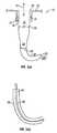
- FIG. 1( a )is a cross-sectional view of one embodiment of a directional probe of the present invention.
- FIG. 1( b )is a cross-sectional view of a probe that is used with the FIG. 1( a ) embodiment.
- FIG. 2is a table summary sample calculations determining the compatibility of a cannula with probes with different diameters from the FIG. 1( a ) embodiment.
- FIG. 3illustrates the relationship of the different diameters of the probe and cannula of the FIG. 1( a ) embodiment.
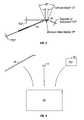
- FIG. 4shows another embodiment of the present invention.
- FIG. 5shows a kit according to the present invention.
- one embodiment of the present inventionis a directional probe, generally denoted as 10 , that has a cannula 12 with a cannula lumen 14 .
- Cannula lumen 14has an average diameter 16 .
- average diameter 16is about from 20-25 gauge. 20 and 25 gauge are both important in ophthalmic surgery. Dimensions much smaller than 25 gauge, higher gauge number, such as 26 gauge, 27, gauge are less important due to incompatibility with existing support instrumentation and the increasing difficulty coupling therapeutic modalities such as laser, electrosurgery, diathermy, and the like.
- a probe 18is positionable in cannula lumen 14 .
- Probe 18has a first section 19 with a first average diameter 21 , a distal portion 20 with a curved section 22 that has at least one radius of curvature and with a second average diameter 23 .
- second average diameteris the range of about 20-30 gauge.
- Second average diameter 23is less than first average diameter.
- directional probe 18is a rigid instrument that offers the treatment access of an angled device and is simultaneously compatible with an instrument introducing cannula. In one embodiment, directional probe 18 is useful for use by ophthalmic surgeons to help introduce instruments into the globe.
- Directional probe 10provides convenience and capability of a standard directional probe in combination with the durability and consistent geometry of a rigid instrument.
- directional probe 10has few if any moving parts. This ensures structural integrity of the inserted portion of the directional probe 10 .
- Directional probe 10can have small dimensions and is particularly useful in ophthalmic and other microsurgeries.
- Directional probe 10can have a monolithic geometry that is stronger than hardware employing flexible or deformable features to simultaneously achieve angulation and cannula compatibility.
- Curved section 22can have numerous radii of curvature.
- the curvature of curved section 22is selected to ensure passage of curved section 22 through the length of cannula 12 without interference.
- the curvature of curved section 22is 3-30 mm.
- radii less than 3 mmare only compatible with extremely short cannula which are used often. Such short radii are also not compatible with the minimum bend radius requirements of most multimode optical fibers.
- radii greater than 30 mmare sometimes larger than the human eye, precluding their use in invasive ophthalmic surgery.
- the curvature of curved section 22that is selected to provide that as distal portion 20 passes through cannula lumen 14 , a first side of distal portion 20 is tangential to a first side of cannula lumen 14 , and a second opposing side of the distal portion 20 is tangential to a second opposing side of cannula lumen 14 .
- a seal 24is created between cannula 12 and probe 18 when the probe is positioned in cannula 12 .
- Seal 24provides a simple close fit of noncompliant materials and surfaces of cannula 12 and probe 18 .
- a major portion of cannula 12has a substantially linear geometry.
- Cannula 12may have a tissue penetrating distal end 26 .
- Probe 18may also have a tissue penetrating distal end 28 .
- Probe 18is rotationally moveable within cannula 12 when positioned in the cannula lumen 14 . Probe 18 is also moveable in a direction, generally denoted as 30 , along a longitudinal axis of cannula 12 when positioned in cannula lumen 14 . A distal portion of probe 18 is configured to provide access to a swept region, denoted as 32 , within a tissue site.
- probe 18has a probe lumen 34 .
- Probe lumen 34is sized to receive a treatment device 36 .
- treatment device 36can be, an optical fiber, an RF electrode, a resistive heating device, an ultrasound device, and the like.
- FIG. 2is a table summary sample calculations determining the compatibility of cannula 12 with probes 18 with different diameters.
- a formulamay be used to determine a clearance S, a length of cannula 2r and resultant minimum bend radius R.
- Table 2also shows Arc length for bends of various degrees and chord lengths for bends of various degrees. These same sizes may be used for embodiments such as those described in FIG. 4 for the probe 50 .
- the cannula 12may have the length of 2r or less.
- FIG. 3relates the various diameters.
- directional probe 10is used for a variety of different methods of treatment.
- Cannula 12is introduced into a tissue.
- Probe 18is introduced through cannula lumen 14 .
- a first side of the curved section 22is tangential to a first side of cannula lumen 14
- a second opposing side of curved section 22is tangential to a second opposing side of cannula lumen 14 .
- Distal portion 20 of probe 18is advanced into a tissue site of the tissue.
- a treatment deviceis introduced through a lumen of probe 18 .
- Treatment devicecan be a variety of different devices, including but not limited to, an optical fiber, an RF electrode.
- Probe 18can then be rotated and/or moved in a longitudinal direction relative to an axis of the cannula lumen 14 .
- the tissue sitecan be a variety of different tissue sites including but not limited to the eye.
- another embodiment of the present inventionmay be divided into two separate pieces, and provide an angled probe 50 with a single outside dimension D 1 that is the smaller of the diameters (30 gauge for example) and separately provide a flexible plastic or slit metal sleeve 52 that can slip over the outside diameter D 1 and provide a seal with the inside diameter D 2 of the cannula (25 gauge for example, not shown for ease of illustration).
- the sleeve 52has a diameter D 3 . In one embodiment, this allows a probe 50 of a constant diameter D 1 to be adapted for use with a larger cannula through the use of a sleeve 52 .
- the probe 50may have a bend radius R sized for use with a cannula (not shown) based on the chart in FIG. 2 .
- the sleeve 52has a constant diameter D 3 .
- the sleeve 52may have a tapered configuration or other configuration with varying diameters.
- FIG. 5shows one embodiment of a kit according to the present invention.
- the kitmay include a container 60 such but not limited to bag, pouch, box, hermetically sealed container, or the like that will receive a probe 18 and at least the instructions for use (IFU) 62 .
- a container 60such but not limited to bag, pouch, box, hermetically sealed container, or the like that will receive a probe 18 and at least the instructions for use (IFU) 62 .
- IFUinstructions for use
- an appropriately sized cannula 12such as described or sized per FIG. 2 may be included in the container 60 .
- Other embodimentsmay substitute probe 18 with probe 50 and sleeve 52 .
- the IFUmay set forth a variety of methods including: providing a treatment device a cannula with a cannula lumen, a probe positionable in the cannula lumen, the probe having a first section with a second average diameter and a second section with a third average diameter that is less than the second average diameter, at least a portion of the second section having a curved section with at least one radius of curvature; introducing a distal section of the cannula into a tissue; introducing the probe through the cannula lumen with a first side of the second section being tangential to a first side of the cannula lumen, and a second opposing side of the second section being tangential to a second opposing side of the cannula lumen; and advancing a distal portion of the probe into a tissue site of the tissue.
Landscapes
- Health & Medical Sciences (AREA)
- Life Sciences & Earth Sciences (AREA)
- Surgery (AREA)
- Engineering & Computer Science (AREA)
- Animal Behavior & Ethology (AREA)
- General Health & Medical Sciences (AREA)
- Biomedical Technology (AREA)
- Heart & Thoracic Surgery (AREA)
- Veterinary Medicine (AREA)
- Nuclear Medicine, Radiotherapy & Molecular Imaging (AREA)
- Public Health (AREA)
- Molecular Biology (AREA)
- Medical Informatics (AREA)
- Pathology (AREA)
- Ophthalmology & Optometry (AREA)
- Oral & Maxillofacial Surgery (AREA)
- Vascular Medicine (AREA)
- Neurology (AREA)
- Neurosurgery (AREA)
- Physics & Mathematics (AREA)
- Plasma & Fusion (AREA)
- Otolaryngology (AREA)
- Surgical Instruments (AREA)
Abstract
Description
Claims (27)
Priority Applications (1)
| Application Number | Priority Date | Filing Date | Title |
|---|---|---|---|
| US11/205,629US7909816B2 (en) | 2004-08-16 | 2005-08-16 | Directional probe treatment apparatus |
Applications Claiming Priority (2)
| Application Number | Priority Date | Filing Date | Title |
|---|---|---|---|
| US60216604P | 2004-08-16 | 2004-08-16 | |
| US11/205,629US7909816B2 (en) | 2004-08-16 | 2005-08-16 | Directional probe treatment apparatus |
Publications (2)
| Publication Number | Publication Date |
|---|---|
| US20060041291A1 US20060041291A1 (en) | 2006-02-23 |
| US7909816B2true US7909816B2 (en) | 2011-03-22 |
Family
ID=36001782
Family Applications (1)
| Application Number | Title | Priority Date | Filing Date |
|---|---|---|---|
| US11/205,629Active2028-05-29US7909816B2 (en) | 2004-08-16 | 2005-08-16 | Directional probe treatment apparatus |
Country Status (2)
| Country | Link |
|---|---|
| US (1) | US7909816B2 (en) |
| DE (1) | DE102005038611B4 (en) |
Cited By (30)
| Publication number | Priority date | Publication date | Assignee | Title |
|---|---|---|---|---|
| US20130267758A1 (en)* | 2008-01-07 | 2013-10-10 | Salutaris Medical Devices, Inc. | Methods and devices for minimally-invasive extraocular delivery of radiation to the posterior portion of the eye |
| US9168174B2 (en) | 2012-05-25 | 2015-10-27 | Ojai Retinal Technology, Llc | Process for restoring responsiveness to medication in tissue of living organisms |
| US9335455B2 (en) | 2012-05-30 | 2016-05-10 | Cygnus, LP | Extended tip laser and illumination probe for retina surgery |
| US9370447B2 (en) | 2011-10-10 | 2016-06-21 | Cygnus LP | Probes for use in ophthalmic and vitreoretinal surgery |
| US9381115B2 (en) | 2012-05-25 | 2016-07-05 | Ojai Retinal Technology, Llc | System and process for retina phototherapy |
| US9381116B2 (en) | 2012-05-25 | 2016-07-05 | Ojai Retinal Technology, Llc | Subthreshold micropulse laser prophylactic treatment for chronic progressive retinal diseases |
| US9427602B2 (en) | 2012-05-25 | 2016-08-30 | Ojai Retinal Technology, Llc | Pulsating electromagnetic and ultrasound therapy for stimulating targeted heat shock proteins and facilitating protein repair |
| US9757536B2 (en) | 2012-07-17 | 2017-09-12 | Novartis Ag | Soft tip cannula |
| USD808528S1 (en) | 2016-08-31 | 2018-01-23 | Salutaris Medical Devices, Inc. | Holder for a brachytherapy device |
| USD808529S1 (en) | 2016-08-31 | 2018-01-23 | Salutaris Medical Devices, Inc. | Holder for a brachytherapy device |
| US9873001B2 (en) | 2008-01-07 | 2018-01-23 | Salutaris Medical Devices, Inc. | Methods and devices for minimally-invasive delivery of radiation to the eye |
| USD814637S1 (en) | 2016-05-11 | 2018-04-03 | Salutaris Medical Devices, Inc. | Brachytherapy device |
| USD814638S1 (en) | 2016-05-11 | 2018-04-03 | Salutaris Medical Devices, Inc. | Brachytherapy device |
| USD815285S1 (en) | 2016-05-11 | 2018-04-10 | Salutaris Medical Devices, Inc. | Brachytherapy device |
| US9962291B2 (en) | 2012-05-25 | 2018-05-08 | Ojai Retinal Technology, Llc | System and process for neuroprotective therapy for glaucoma |
| US10022558B1 (en) | 2008-01-07 | 2018-07-17 | Salutaris Medical Devices, Inc. | Methods and devices for minimally-invasive delivery of radiation to the eye |
| US10076671B2 (en) | 2012-05-25 | 2018-09-18 | Ojai Retinal Technology, Llc | Apparatus for retina phototherapy |
| US10219947B2 (en) | 2012-05-25 | 2019-03-05 | Ojai Retinal Technology, Llc | System and process for retina phototherapy |
| US10278863B2 (en) | 2016-03-21 | 2019-05-07 | Ojai Retinal Technology, Llc | System and process for treatment of myopia |
| US10531908B2 (en) | 2012-05-25 | 2020-01-14 | Ojai Retinal Technology, Llc | Method for heat treating biological tissues using pulsed energy sources |
| US10596389B2 (en) | 2012-05-25 | 2020-03-24 | Ojai Retinal Technology, Llc | Process and system for utilizing energy to treat biological tissue |
| US10709608B2 (en) | 2016-03-21 | 2020-07-14 | Ojai Retinal Technology, Llc | System and process for prevention of myopia |
| US10874873B2 (en) | 2012-05-25 | 2020-12-29 | Ojai Retinal Technology, Llc | Process utilizing pulsed energy to heat treat biological tissue |
| US10894169B2 (en) | 2012-05-25 | 2021-01-19 | Ojai Retinal Technology, Llc | System and method for preventing or treating Alzheimer's and other neurodegenerative diseases |
| US10953241B2 (en) | 2012-05-25 | 2021-03-23 | Ojai Retinal Technology, Llc | Process for providing protective therapy for biological tissues or fluids |
| US11077318B2 (en) | 2012-05-25 | 2021-08-03 | Ojai Retinal Technology, Llc | System and process of utilizing energy for treating biological tissue |
| US11493692B2 (en) | 2020-02-18 | 2022-11-08 | Alcon Inc. | Multi-spot laser probe with multiple single-core fibers |
| US11540941B2 (en) | 2019-12-11 | 2023-01-03 | Alcon Inc. | Adjustable support sleeve for surgical instruments |
| US11998483B2 (en) | 2019-12-11 | 2024-06-04 | Alcon Inc. | Adjustable stiffener for surgical instruments |
| US12186236B2 (en) | 2021-08-26 | 2025-01-07 | Alcon Inc. | Adjustable stiffener for surgical instruments |
Families Citing this family (7)
| Publication number | Priority date | Publication date | Assignee | Title |
|---|---|---|---|---|
| US20070106301A1 (en)* | 2005-11-09 | 2007-05-10 | Alcon, Inc. | Sclerotomy adapter |
| US20090024042A1 (en)* | 2007-07-03 | 2009-01-22 | Endotronix, Inc. | Method and system for monitoring ventricular function of a heart |
| US20120265010A1 (en)* | 2011-04-12 | 2012-10-18 | Endo Optiks, Inc. | Laser Video Endoscope |
| US9949876B2 (en)* | 2014-03-05 | 2018-04-24 | Cygnus LP | Small gauge instruments for micro surgery |
| US9999542B2 (en) | 2014-07-16 | 2018-06-19 | Doheny Eye Institute | Systems, methods, and devices for cannula insertion |
| EP3582728A4 (en)* | 2017-02-16 | 2020-11-25 | Microsurgical Technology, Inc. | Devices, systems and methods for minimally invasive glaucoma surgery |
| US10413324B2 (en)* | 2017-10-23 | 2019-09-17 | Conmed Corporation | Devices for performing minimally invasive surgery having foam support housing |
Citations (9)
| Publication number | Priority date | Publication date | Assignee | Title |
|---|---|---|---|---|
| US4537193A (en) | 1982-10-28 | 1985-08-27 | Hgm, Inc. | Laser endocoagulator apparatus |
| US4593691A (en)* | 1983-07-13 | 1986-06-10 | Concept, Inc. | Electrosurgery electrode |
| US4822360A (en)* | 1988-03-16 | 1989-04-18 | University Of Utah | Inflatable, intraocular lens and method of implanting the lens in the capsule of an eye |
| US4863430A (en)* | 1987-08-26 | 1989-09-05 | Surgical Dynamics, Inc. | Introduction set with flexible trocar with curved cannula |
| US5755714A (en)* | 1996-09-17 | 1998-05-26 | Eclipse Surgical Technologies, Inc. | Shaped catheter for transmyocardial revascularization |
| US6142990A (en)* | 1997-02-15 | 2000-11-07 | Heidelberg Engineering Optische Messsysteme Gmbh | Medical apparatus, especially for reducing intraocular pressure |
| US20020087047A1 (en)* | 1999-09-13 | 2002-07-04 | Visionscope, Inc. | Miniature endoscope system |
| US20030191461A1 (en)* | 2000-04-07 | 2003-10-09 | Synergetics, Inc., A Corporation | Directional laser probe |
| US6752608B1 (en)* | 2003-05-29 | 2004-06-22 | Tecumseh Products Company | Compressor crankshaft with bearing sleeve and assembly method |
Family Cites Families (5)
| Publication number | Priority date | Publication date | Assignee | Title |
|---|---|---|---|---|
| US4230123A (en) | 1978-10-31 | 1980-10-28 | Hawkins Jr Irvin F | Needle sheath complex and process for decompression and biopsy |
| US4827941A (en) | 1987-12-23 | 1989-05-09 | Advanced Cardiovascular Systems, Inc. | Extendable guidewire for cardiovascular procedures |
| JP2681073B2 (en) | 1989-01-17 | 1997-11-19 | 則雄 大工園 | Laser light emitting probe and manufacturing method thereof |
| US5282796A (en) | 1991-01-14 | 1994-02-01 | Knoepfler Dennis J | Scopic probe |
| US6916000B2 (en) | 1998-07-02 | 2005-07-12 | Jeffrey N. Weiss | Apparatus and method for cannulating retinal blood vessels |
- 2005
- 2005-08-16USUS11/205,629patent/US7909816B2/enactiveActive
- 2005-08-16DEDE102005038611.3Apatent/DE102005038611B4/ennot_activeExpired - Lifetime
Patent Citations (10)
| Publication number | Priority date | Publication date | Assignee | Title |
|---|---|---|---|---|
| US4537193A (en) | 1982-10-28 | 1985-08-27 | Hgm, Inc. | Laser endocoagulator apparatus |
| US4593691A (en)* | 1983-07-13 | 1986-06-10 | Concept, Inc. | Electrosurgery electrode |
| US4863430A (en)* | 1987-08-26 | 1989-09-05 | Surgical Dynamics, Inc. | Introduction set with flexible trocar with curved cannula |
| US4822360A (en)* | 1988-03-16 | 1989-04-18 | University Of Utah | Inflatable, intraocular lens and method of implanting the lens in the capsule of an eye |
| US5755714A (en)* | 1996-09-17 | 1998-05-26 | Eclipse Surgical Technologies, Inc. | Shaped catheter for transmyocardial revascularization |
| US6142990A (en)* | 1997-02-15 | 2000-11-07 | Heidelberg Engineering Optische Messsysteme Gmbh | Medical apparatus, especially for reducing intraocular pressure |
| US20020087047A1 (en)* | 1999-09-13 | 2002-07-04 | Visionscope, Inc. | Miniature endoscope system |
| US20030191461A1 (en)* | 2000-04-07 | 2003-10-09 | Synergetics, Inc., A Corporation | Directional laser probe |
| US6984230B2 (en)* | 2000-04-07 | 2006-01-10 | Synergetics, Inc. | Directional laser probe |
| US6752608B1 (en)* | 2003-05-29 | 2004-06-22 | Tecumseh Products Company | Compressor crankshaft with bearing sleeve and assembly method |
Non-Patent Citations (1)
| Title |
|---|
| IRIDEX Press Release, "IRIDEX Expands EndoPorbe product Family With Unique Stepping Probes" (Apr. 16, 2005) IRIDEX Corporation, 1212 Terra Bella Avenue, Mountain View, CA , 94043-1824, 2 pages total. |
Cited By (43)
| Publication number | Priority date | Publication date | Assignee | Title |
|---|---|---|---|---|
| US9873001B2 (en) | 2008-01-07 | 2018-01-23 | Salutaris Medical Devices, Inc. | Methods and devices for minimally-invasive delivery of radiation to the eye |
| US10850118B2 (en) | 2008-01-07 | 2020-12-01 | Salutaris Medical Devices, Inc. | Methods and devices for minim ally-invasive delivery of radiation to the eye |
| US20130267758A1 (en)* | 2008-01-07 | 2013-10-10 | Salutaris Medical Devices, Inc. | Methods and devices for minimally-invasive extraocular delivery of radiation to the posterior portion of the eye |
| US10022558B1 (en) | 2008-01-07 | 2018-07-17 | Salutaris Medical Devices, Inc. | Methods and devices for minimally-invasive delivery of radiation to the eye |
| US9370447B2 (en) | 2011-10-10 | 2016-06-21 | Cygnus LP | Probes for use in ophthalmic and vitreoretinal surgery |
| US10278865B2 (en) | 2012-05-25 | 2019-05-07 | Ojai Retinal Technology, Llc | Process for neuroprotective therapy for glaucoma |
| US10219947B2 (en) | 2012-05-25 | 2019-03-05 | Ojai Retinal Technology, Llc | System and process for retina phototherapy |
| US10874873B2 (en) | 2012-05-25 | 2020-12-29 | Ojai Retinal Technology, Llc | Process utilizing pulsed energy to heat treat biological tissue |
| US12377283B2 (en) | 2012-05-25 | 2025-08-05 | Ojai Retinal Technology, Llc | System and process of utilizing microwave energy for treating biological tissue |
| US11077318B2 (en) | 2012-05-25 | 2021-08-03 | Ojai Retinal Technology, Llc | System and process of utilizing energy for treating biological tissue |
| US9381116B2 (en) | 2012-05-25 | 2016-07-05 | Ojai Retinal Technology, Llc | Subthreshold micropulse laser prophylactic treatment for chronic progressive retinal diseases |
| US11033749B2 (en) | 2012-05-25 | 2021-06-15 | Ojai Retinal Technology, Llc | Process utilizing pulsed energy to heat treat biological tissue |
| US10953241B2 (en) | 2012-05-25 | 2021-03-23 | Ojai Retinal Technology, Llc | Process for providing protective therapy for biological tissues or fluids |
| US10952901B2 (en) | 2012-05-25 | 2021-03-23 | Ojai Retinal Technology, Llc | System and process for retina phototherapy |
| US9962291B2 (en) | 2012-05-25 | 2018-05-08 | Ojai Retinal Technology, Llc | System and process for neuroprotective therapy for glaucoma |
| US9381115B2 (en) | 2012-05-25 | 2016-07-05 | Ojai Retinal Technology, Llc | System and process for retina phototherapy |
| US10076671B2 (en) | 2012-05-25 | 2018-09-18 | Ojai Retinal Technology, Llc | Apparatus for retina phototherapy |
| US10117777B2 (en) | 2012-05-25 | 2018-11-06 | Ojai Retinal Technology, Llc | System for neuroprotective therapy for glaucoma |
| US9427602B2 (en) | 2012-05-25 | 2016-08-30 | Ojai Retinal Technology, Llc | Pulsating electromagnetic and ultrasound therapy for stimulating targeted heat shock proteins and facilitating protein repair |
| US10238542B2 (en) | 2012-05-25 | 2019-03-26 | Ojai Retinal Technology, Llc | System and process for retina phototherapy |
| US10596389B2 (en) | 2012-05-25 | 2020-03-24 | Ojai Retinal Technology, Llc | Process and system for utilizing energy to treat biological tissue |
| US9168174B2 (en) | 2012-05-25 | 2015-10-27 | Ojai Retinal Technology, Llc | Process for restoring responsiveness to medication in tissue of living organisms |
| US10285859B2 (en) | 2012-05-25 | 2019-05-14 | Ojai Retinal Technology, Llc | System for performing retina photostimulation |
| US10299961B2 (en) | 2012-05-25 | 2019-05-28 | Ojai Retinal Technology, Llc | System for neuroprotective therapy for glaucoma |
| US10307294B2 (en) | 2012-05-25 | 2019-06-04 | Ojai Retinal Technology, Llc | System and process for neuroprotective therapy for glaucoma |
| US10894169B2 (en) | 2012-05-25 | 2021-01-19 | Ojai Retinal Technology, Llc | System and method for preventing or treating Alzheimer's and other neurodegenerative diseases |
| US10363171B2 (en) | 2012-05-25 | 2019-07-30 | Ojai Retinal Technology, Llc | System and process for retina phototherapy |
| US10531908B2 (en) | 2012-05-25 | 2020-01-14 | Ojai Retinal Technology, Llc | Method for heat treating biological tissues using pulsed energy sources |
| US9335455B2 (en) | 2012-05-30 | 2016-05-10 | Cygnus, LP | Extended tip laser and illumination probe for retina surgery |
| US9757536B2 (en) | 2012-07-17 | 2017-09-12 | Novartis Ag | Soft tip cannula |
| US10278863B2 (en) | 2016-03-21 | 2019-05-07 | Ojai Retinal Technology, Llc | System and process for treatment of myopia |
| US10709607B2 (en) | 2016-03-21 | 2020-07-14 | Ojai Retinal Technology, Llc | System and process for treatment of myopia |
| US10709608B2 (en) | 2016-03-21 | 2020-07-14 | Ojai Retinal Technology, Llc | System and process for prevention of myopia |
| US10357398B2 (en) | 2016-03-21 | 2019-07-23 | Ojai Retinal Technology, Llc | System and process for treatment of myopia |
| USD815285S1 (en) | 2016-05-11 | 2018-04-10 | Salutaris Medical Devices, Inc. | Brachytherapy device |
| USD814638S1 (en) | 2016-05-11 | 2018-04-03 | Salutaris Medical Devices, Inc. | Brachytherapy device |
| USD814637S1 (en) | 2016-05-11 | 2018-04-03 | Salutaris Medical Devices, Inc. | Brachytherapy device |
| USD808529S1 (en) | 2016-08-31 | 2018-01-23 | Salutaris Medical Devices, Inc. | Holder for a brachytherapy device |
| USD808528S1 (en) | 2016-08-31 | 2018-01-23 | Salutaris Medical Devices, Inc. | Holder for a brachytherapy device |
| US11540941B2 (en) | 2019-12-11 | 2023-01-03 | Alcon Inc. | Adjustable support sleeve for surgical instruments |
| US11998483B2 (en) | 2019-12-11 | 2024-06-04 | Alcon Inc. | Adjustable stiffener for surgical instruments |
| US11493692B2 (en) | 2020-02-18 | 2022-11-08 | Alcon Inc. | Multi-spot laser probe with multiple single-core fibers |
| US12186236B2 (en) | 2021-08-26 | 2025-01-07 | Alcon Inc. | Adjustable stiffener for surgical instruments |
Also Published As
| Publication number | Publication date |
|---|---|
| DE102005038611A1 (en) | 2006-03-23 |
| DE102005038611B4 (en) | 2023-01-12 |
| US20060041291A1 (en) | 2006-02-23 |
Similar Documents
| Publication | Publication Date | Title |
|---|---|---|
| US7909816B2 (en) | Directional probe treatment apparatus | |
| JP6017759B2 (en) | Cannula | |
| US8323291B2 (en) | Partial aiming device for targeting an arthroscopic operation site for a medical intervention | |
| US5593416A (en) | Method of using flexible surgical instrument | |
| JP6180575B2 (en) | Ultrasound puncture needle | |
| US8657749B2 (en) | Ultrasonic puncture needle | |
| JP5420857B2 (en) | Obturator tip | |
| EP2087846A2 (en) | Access assembly with spherical valve | |
| US6663605B2 (en) | Removable protective cannula for use in surgery | |
| US20090093800A1 (en) | Flexible Surgical Probe | |
| US8506475B2 (en) | Flexible scope endoscope | |
| US20080234713A1 (en) | Shaver blade with depth markings | |
| CN105338910A (en) | Stabilization device and method for medical surgery | |
| US6613065B2 (en) | Device for guiding a medical instrument | |
| JP2013519492A (en) | Multiple fiber surgical probe with flexibility | |
| JP7599265B2 (en) | Ophthalmic Microsurgery Instruments | |
| US20070197958A1 (en) | Probe for insertion in the anal canal and rectum of a body | |
| US20070239119A1 (en) | Adjustable curved needle | |
| US11071448B2 (en) | Length adjustable cannula | |
| JP2011125701A (en) | Obturator tip | |
| JP5249231B2 (en) | Dilatation cannula | |
| JPH02174858A (en) | Embolus device | |
| US20030088257A1 (en) | Directional endo-illuminator | |
| CA2257069C (en) | Flexible surgical instrument and method | |
| US20250312061A1 (en) | Arthroscopic Cannula and Insertion Tool |
Legal Events
| Date | Code | Title | Description |
|---|---|---|---|
| AS | Assignment | Owner name:IRIDEX CORPORATION, CALIFORNIA Free format text:ASSIGNMENT OF ASSIGNORS INTEREST;ASSIGNOR:BUZAWA, DAVID M.;REEL/FRAME:017188/0450 Effective date:20051006 | |
| AS | Assignment | Owner name:WELLS FARGO BANK NATIONAL ASSOCIATION, CALIFORNIA Free format text:SECURITY AGREEMENT;ASSIGNOR:IRIDEX CORPORATION, A DELAWARE CORPORATION;REEL/FRAME:020773/0767 Effective date:20080327 | |
| STCF | Information on status: patent grant | Free format text:PATENTED CASE | |
| FPAY | Fee payment | Year of fee payment:4 | |
| MAFP | Maintenance fee payment | Free format text:PAYMENT OF MAINTENANCE FEE, 8TH YR, SMALL ENTITY (ORIGINAL EVENT CODE: M2552); ENTITY STATUS OF PATENT OWNER: SMALL ENTITY Year of fee payment:8 | |
| MAFP | Maintenance fee payment | Free format text:PAYMENT OF MAINTENANCE FEE, 12TH YR, SMALL ENTITY (ORIGINAL EVENT CODE: M2553); ENTITY STATUS OF PATENT OWNER: SMALL ENTITY Year of fee payment:12 | |
| AS | Assignment | Owner name:IRIDEX CORPORATION, CALIFORNIA Free format text:RELEASE OF SECURITY INTEREST BY DECLARATION;ASSIGNOR:WELLS FARGO BANK, NATIONAL ASSOCIATION;REEL/FRAME:067128/0897 Effective date:20240416 |