US7909798B2 - Peel-away introducer sheath having pitched peel lines and method of making same - Google Patents
Peel-away introducer sheath having pitched peel lines and method of making sameDownload PDFInfo
- Publication number
- US7909798B2 US7909798B2US12/220,378US22037808AUS7909798B2US 7909798 B2US7909798 B2US 7909798B2US 22037808 AUS22037808 AUS 22037808AUS 7909798 B2US7909798 B2US 7909798B2
- Authority
- US
- United States
- Prior art keywords
- peel
- sheath
- lines
- recited
- vascular introducer
- Prior art date
- Legal status (The legal status is an assumption and is not a legal conclusion. Google has not performed a legal analysis and makes no representation as to the accuracy of the status listed.)
- Active, expires
Links
- 238000004519manufacturing processMethods0.000titledescription2
- 230000002792vascularEffects0.000claimsabstractdescription21
- 239000000463materialSubstances0.000claimsdescription7
- 229920002614Polyether block amidePolymers0.000claimsdescription5
- 238000000034methodMethods0.000description9
- 238000001125extrusionMethods0.000description5
- 230000004048modificationEffects0.000description4
- 238000012986modificationMethods0.000description4
- 229920001400block copolymerPolymers0.000description2
- 238000003780insertionMethods0.000description2
- 230000037431insertionEffects0.000description2
- 238000000926separation methodMethods0.000description2
- 241000272201ColumbiformesSpecies0.000description1
- 230000015572biosynthetic processEffects0.000description1
- 229920001577copolymerPolymers0.000description1
- 238000005755formation reactionMethods0.000description1
- 230000007257malfunctionEffects0.000description1
- 238000010008shearingMethods0.000description1
- 210000005166vasculatureAnatomy0.000description1
- 210000003462veinAnatomy0.000description1
Images


Classifications
- A—HUMAN NECESSITIES
- A61—MEDICAL OR VETERINARY SCIENCE; HYGIENE
- A61M—DEVICES FOR INTRODUCING MEDIA INTO, OR ONTO, THE BODY; DEVICES FOR TRANSDUCING BODY MEDIA OR FOR TAKING MEDIA FROM THE BODY; DEVICES FOR PRODUCING OR ENDING SLEEP OR STUPOR
- A61M25/00—Catheters; Hollow probes
- A61M25/01—Introducing, guiding, advancing, emplacing or holding catheters
- A61M25/06—Body-piercing guide needles or the like
- A61M25/0662—Guide tubes
- A61M25/0668—Guide tubes splittable, tear apart
- B—PERFORMING OPERATIONS; TRANSPORTING
- B29—WORKING OF PLASTICS; WORKING OF SUBSTANCES IN A PLASTIC STATE IN GENERAL
- B29C—SHAPING OR JOINING OF PLASTICS; SHAPING OF MATERIAL IN A PLASTIC STATE, NOT OTHERWISE PROVIDED FOR; AFTER-TREATMENT OF THE SHAPED PRODUCTS, e.g. REPAIRING
- B29C48/00—Extrusion moulding, i.e. expressing the moulding material through a die or nozzle which imparts the desired form; Apparatus therefor
- B29C48/03—Extrusion moulding, i.e. expressing the moulding material through a die or nozzle which imparts the desired form; Apparatus therefor characterised by the shape of the extruded material at extrusion
- B29C48/09—Articles with cross-sections having partially or fully enclosed cavities, e.g. pipes or channels
- B29C48/11—Articles with cross-sections having partially or fully enclosed cavities, e.g. pipes or channels comprising two or more partially or fully enclosed cavities, e.g. honeycomb-shaped
- B—PERFORMING OPERATIONS; TRANSPORTING
- B29—WORKING OF PLASTICS; WORKING OF SUBSTANCES IN A PLASTIC STATE IN GENERAL
- B29C—SHAPING OR JOINING OF PLASTICS; SHAPING OF MATERIAL IN A PLASTIC STATE, NOT OTHERWISE PROVIDED FOR; AFTER-TREATMENT OF THE SHAPED PRODUCTS, e.g. REPAIRING
- B29C48/00—Extrusion moulding, i.e. expressing the moulding material through a die or nozzle which imparts the desired form; Apparatus therefor
- B29C48/03—Extrusion moulding, i.e. expressing the moulding material through a die or nozzle which imparts the desired form; Apparatus therefor characterised by the shape of the extruded material at extrusion
- B29C48/12—Articles with an irregular circumference when viewed in cross-section, e.g. window profiles
- B—PERFORMING OPERATIONS; TRANSPORTING
- B29—WORKING OF PLASTICS; WORKING OF SUBSTANCES IN A PLASTIC STATE IN GENERAL
- B29C—SHAPING OR JOINING OF PLASTICS; SHAPING OF MATERIAL IN A PLASTIC STATE, NOT OTHERWISE PROVIDED FOR; AFTER-TREATMENT OF THE SHAPED PRODUCTS, e.g. REPAIRING
- B29C2793/00—Shaping techniques involving a cutting or machining operation
- B29C2793/0054—Shaping techniques involving a cutting or machining operation partially cutting through the material
- B—PERFORMING OPERATIONS; TRANSPORTING
- B29—WORKING OF PLASTICS; WORKING OF SUBSTANCES IN A PLASTIC STATE IN GENERAL
- B29C—SHAPING OR JOINING OF PLASTICS; SHAPING OF MATERIAL IN A PLASTIC STATE, NOT OTHERWISE PROVIDED FOR; AFTER-TREATMENT OF THE SHAPED PRODUCTS, e.g. REPAIRING
- B29C48/00—Extrusion moulding, i.e. expressing the moulding material through a die or nozzle which imparts the desired form; Apparatus therefor
- B29C48/25—Component parts, details or accessories; Auxiliary operations
- B29C48/30—Extrusion nozzles or dies
- B29C48/32—Extrusion nozzles or dies with annular openings, e.g. for forming tubular articles
- B—PERFORMING OPERATIONS; TRANSPORTING
- B29—WORKING OF PLASTICS; WORKING OF SUBSTANCES IN A PLASTIC STATE IN GENERAL
- B29K—INDEXING SCHEME ASSOCIATED WITH SUBCLASSES B29B, B29C OR B29D, RELATING TO MOULDING MATERIALS OR TO MATERIALS FOR MOULDS, REINFORCEMENTS, FILLERS OR PREFORMED PARTS, e.g. INSERTS
- B29K2995/00—Properties of moulding materials, reinforcements, fillers, preformed parts or moulds
- B29K2995/0037—Other properties
- B29K2995/0082—Flexural strength; Flexion stiffness
- B—PERFORMING OPERATIONS; TRANSPORTING
- B29—WORKING OF PLASTICS; WORKING OF SUBSTANCES IN A PLASTIC STATE IN GENERAL
- B29L—INDEXING SCHEME ASSOCIATED WITH SUBCLASS B29C, RELATING TO PARTICULAR ARTICLES
- B29L2031/00—Other particular articles
- B29L2031/753—Medical equipment; Accessories therefor
- B29L2031/7546—Surgical equipment
Definitions
- the subject technologyrelates to a vascular introducer, and more particularly, to a vascular introducer having a peel-away sheath with pitched peel lines and to a method of forming the same by way of extrusion.
- Introducer deviceshave been employed for inserting catheters, guide wires, leads and the like into patients.
- a typical procedureprovides for insertion of a dilator or needle encased within a sheath into the vasculature of a patient.
- the dilator or needlemay be removed leaving the sheath protruding from the patient's vein.
- the sheathis then removed.
- the sheathmay be split or peeled away along two diametrically opposed score lines.
- the sheathmay be slit open using a specialized cutting blade.
- splittable or peelable introducer sheathsare shown in U.S. Pat. No. 6,494,860 to Rocamora et al. and U.S. Pat. No. 7,192,433 to Osypka et al., the disclosures of which are herein incorporated by reference in their entireties.
- splittable introducer sheathsare prepared by forming straight score lines along the length of the sheath using a mandrel.
- An example of a device for slitting an introducer sheathis disclosed in U.S. Pat. No. 4,687,469 to Osypka, the disclosure of which is also incorporated herein by reference in its entirety.
- Typical slitter devicesinclude a body or handle portion with a cutting edge or knife secured thereto such that the cutting edge may be manually guided to cut the sheath.
- peelable sheaths and slitting devicesThere are drawbacks associated with peelable sheaths and slitting devices.
- peelable sheaths with straight score linesdo not evenly distribute the shearing forces during peeling. This can make operation difficult or even result in malfunction such as partial or uneven separation.
- slitting devicesthe expense of providing a separate device can be significant.
- the manual dexterity required to operate a slittercan be undesirably high. There is a need, therefore, for an improved sheath which evenly distributes sheering forces, is efficient to fabricate and easy to use as well as assuring adequate separation.
- the subject technologyis directed to a new and useful percutaneous peel-away vascular introducer that includes an elongated tubular sheath having opposed proximal and distal ends, and a pair of diametrically opposed peel lines that extend along the length of the sheath from the proximal end thereof to the distal end thereof, wherein the diametrically opposed peel lines have an axially extending pitch.
- the introducerfurther includes a pair of spreadable handles associated with the proximal end of the sheath for splitting the sheath along the peel lines.
- the axially extending pitch of the peel linesis between about 5° and 45°.
- the opposed peel linesare defined by axially extending regions of reduced wall thickness, relative to the wall thickness of the remainder of the sheath.
- Each axially extending region of reduced wall thicknessis preferably defined by a concave or flattened outer wall surface and a corresponding concave inner wall surface.
- the radius of curvature of the concave inner wall surfaceis greater than the radius of curvature of the concave outer wall surface.
- the tubular introducer sheathis formed from a polymeric material in an extrusion process.
- the polymeric materialmay be a block copolymer such as Pebax® copolymer available from Arkema of Colombes, France.
- the block copolymer materialis fed through a unique die while an extruding machine imparts a controlled rotation to the material. This rotation causes a gradual pitch of the peel lines.
- a peel-away vascular introducerin accordance with another preferred embodiment of the subject technology, includes an elongated tubular sheath having opposed proximal and distal ends, and a pair of opposing peel lines extending from the proximal end thereof to the distal end thereof, wherein the opposed peel lines at least partially extend around an axis of the sheath.
- the peel-away vascular introducermay include spreadable handles associated with the proximal end of the sheath for splitting the sheath along the peel lines.
- a method of forming a tubular sheath for an introducer assemblyincludes the steps of forming a tubular structure in an extrusion process and forming opposed peel lines in the tubular structure, wherein the peel lines have an axially extending pitch.
- the methodmay include the step of forcing a molten polymeric extrudate through a die in a rotating motion to create the pitch, wherein a continuously rotating mixer is used to create the rotating motion.
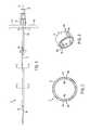
- FIG. 1is a side elevational view of a percutaneous introducer constructed in accordance with a preferred embodiment of the subject technology, which includes pitched peel lines for splitting the introducer sheath;
- FIG. 2is a cross-sectional view of the peel-away introducer sheath taken along line 2 - 2 of FIG. 1 ;
- FIG. 3is a perspective view of an axial section of the peel-away introducer sheath taken along line 3 - 3 of FIG. 1 ;
- FIG. 4Ais a cross-sectional view of an alternative peel-away introducer sheath constructed in accordance with a preferred embodiment of the subject technology
- FIG. 4Bis a cross-sectional view of an alternative peel-away introducer sheath constructed in accordance with a preferred embodiment of the subject technology
- FIG. 4Cis a cross-sectional view of an alternative peel-away introducer sheath constructed in accordance with a preferred embodiment of the subject technology
- FIG. 4Dis a cross-sectional view of an alternative peel-away introducer sheath constructed in accordance with a preferred embodiment of the subject technology.
- FIG. 4Eis a cross-sectional view of an alternative peel-away introducer sheath constructed in accordance with a preferred embodiment of the subject technology.
- vascular introducer assembly 10that includes an elongated tubular sheath 12 defining opposed proximal and distal end portions 12 a , 12 b .
- a handle assembly 14is operatively associated with the proximal end portion 12 a of the tubular sheath 12 .
- the handle assembly 14includes a central hub 16 with a central parting line 16 a defining a pair of opposed radially outwardly extending spreadable/separable handles 14 a , 14 b.
- the introducer assembly 10further includes an elongated dilator 20 having a tapered distal end portion 22 and a proximal leur lock fitting 24 . While not shown herein, the central hub 16 of the handle assembly 14 is adapted and configured to threadably receive the dilator 20 , as disclosed in U.S. Pat. No. 7,192,433, which is incorporated herein by reference.
- FIG. 2a cross-sectional view of the peel-away introducer sheath taken along line 2 - 2 of FIG. 1 and in FIG. 3 a perspective view of an axial section of the peel-away introducer sheath taken along line 3 - 3 of FIG. 1 .
- the tubular sheath 12includes a pair of diametrically opposed peel lines 30 a , 30 b that extend along a longitudinal axis 38 of the sheath 12 from the proximal end 12 a thereof to the distal end 12 b thereof.
- These diametrically opposed peel lines 30 a , 30 bhave an axially extending pitch, at least partially wrapping about the axis 38 of the sheath 12 , as best seen in FIG. 1 .
- the axially extending pitch of the peel lines 30 a , 30 bis about between 5° and 45° although variations well outside this range are also contemplated. Therefore, and as shown in the illustrated embodiment of FIG.
- each opposed peel line 30 a , 30 bhas an axially extending pitch extending between the proximal 12 a and distal 12 b ends of the tubular sheath 12 relative to the longitudinal axis 38 of the sheath 12 wherein each axially extending pitch is located entirely within the upper circumferential half portion of the elongated tubular sheath.
- the opposed peel lines 30 a , 30 bare defined by axially extending regions of reduced wall thickness.
- the axially extending pitch of the peel lines 30 a , 30 bserves to distribute the sheering forces exerted during the peeling process over a greater amount of the surface area of the sheath 12 , as compared to prior art devices having straight peel lines. Hence, deviation from tearing along the peel lines 30 a , 30 b is prevented.
- each peel line 30 a , 30 bis an axially extending region of reduced wall thickness preferably defined by a concave inner wall surface 32 a , 32 b and a corresponding concave or otherwise flattened outer wall surface 34 a , 34 b .
- the radius of curvature of the concave inner wall surfaces 32 a , 32 bis greater than the radius of curvature of the concave outer wall surfaces 34 a , 34 b .
- the peel lines 30 a , 30 bmay formed by perforations or any other frangible connection now known or later developed.
- FIGS. 4A-4Ecross-sectional views of alternative peel-away introducer sheath 12 A-E are shown.
- the sheaths 12 A-Eutilizes similar principles to the sheath 12 described above. Accordingly, the sheaths of FIGS. 4A-E are appended with the letters A-E, respectively, and like structural elements are preceded by the numerals “1-5”, respectively, to indicate like elements.
- the primary difference of the sheaths 12 A-E in comparison to the sheath 12is the shape of the inner walls 32 a , 32 b and outer walls 34 a , 34 b.
- the inner walls 132 a , 132 b of the sheath 12 Aform a valley with no modification of the outer wall 134 a , 134 b .
- the valleymay come to a point such as an intersection between two lines or be a rounded shape such as a semi-circle.
- the sheath 12 B of FIG. 4Bhas similar valley-shaped inner walls 232 a , 232 b with corresponding valley-shaped outer walls 234 a , 234 b .
- the peel linecan be made very thin.
- the inner walls 332 a , 332 b of the sheath 12 Cform a rectangular channel with no modification of the outer wall 334 a , 334 b.
- the inner walls 432 a , 432 b of the sheath 12 Dform a trapezoidal channel also with no modification of the outer wall 434 a , 434 b .
- the peel lines of the sheath 12 Eare formed by axial channels intermediate the inner and outer walls 532 a , 532 b , 534 a , 534 b such that the sheath 12 E may appear unmodified except in cross-sectional view.
- the peel linesare perforated lines. It is envisioned that the various wall formations may be mixed and matched as well as combined with other variations to form a desired peel-away sheath.
- the tubular sheath 12 of introducer assembly 10is formed in an extrusion process using a polymeric material, such as, for example, the Polyether Block Amide (PEBA) manufactured by Arkema under the tradename Pebax® or a similar material.
- PEBAPolyether Block Amide
- the molten polymeric extrudateis forced through a die by a continuously rotating mixer such as a screw or flighted barrel.
- the rotating motionimparts movement that creates the pitch of the regions of reduced wall thickness, and thus the opposed peel lines 30 a , 30 b .
- the rotating motioncan be controlled to vary the pitch of the peel lines 30 a , 30 b .
- the rotational speedcan be increased to increase the pitch of the peel lines 30 a , 30 b , and vice versa.
Landscapes
- Engineering & Computer Science (AREA)
- Mechanical Engineering (AREA)
- Health & Medical Sciences (AREA)
- Life Sciences & Earth Sciences (AREA)
- Biophysics (AREA)
- Pulmonology (AREA)
- Anesthesiology (AREA)
- Biomedical Technology (AREA)
- Heart & Thoracic Surgery (AREA)
- Hematology (AREA)
- Animal Behavior & Ethology (AREA)
- General Health & Medical Sciences (AREA)
- Public Health (AREA)
- Veterinary Medicine (AREA)
- Media Introduction/Drainage Providing Device (AREA)
Abstract
Description
Claims (14)
Priority Applications (1)
| Application Number | Priority Date | Filing Date | Title |
|---|---|---|---|
| US12/220,378US7909798B2 (en) | 2007-07-25 | 2008-07-24 | Peel-away introducer sheath having pitched peel lines and method of making same |
Applications Claiming Priority (2)
| Application Number | Priority Date | Filing Date | Title |
|---|---|---|---|
| US96185607P | 2007-07-25 | 2007-07-25 | |
| US12/220,378US7909798B2 (en) | 2007-07-25 | 2008-07-24 | Peel-away introducer sheath having pitched peel lines and method of making same |
Publications (2)
| Publication Number | Publication Date |
|---|---|
| US20090030374A1 US20090030374A1 (en) | 2009-01-29 |
| US7909798B2true US7909798B2 (en) | 2011-03-22 |
Family
ID=40296020
Family Applications (1)
| Application Number | Title | Priority Date | Filing Date |
|---|---|---|---|
| US12/220,378Active2028-08-27US7909798B2 (en) | 2007-07-25 | 2008-07-24 | Peel-away introducer sheath having pitched peel lines and method of making same |
Country Status (1)
| Country | Link |
|---|---|
| US (1) | US7909798B2 (en) |
Cited By (31)
| Publication number | Priority date | Publication date | Assignee | Title |
|---|---|---|---|---|
| US20110218549A1 (en)* | 2010-03-05 | 2011-09-08 | Boston Scientific Neuromodulation Corporation | Systems and methods for making and using a trial stimulation system having an electrical connector disposed on a trial stimulation lead |
| US20110224680A1 (en)* | 2010-03-10 | 2011-09-15 | Boston Scientific Neuromodulation Corporation | System and method for making and using a lead introducer for an implantable electrical stimulation system |
| US20110224681A1 (en)* | 2010-03-15 | 2011-09-15 | Boston Scientific Neuromodulation Corporation | System and method for making and using a splitable lead introducer for an implantable electrical stimulation system |
| US20110230893A1 (en)* | 2010-03-19 | 2011-09-22 | Boston Scientific Neuromodulation Corporation | Systems and methods for making and using electrical stimulation systems having multi-lead-element lead bodies |
| US20140135786A1 (en)* | 2012-11-09 | 2014-05-15 | Naris Llc | Medical procedure access kit |
| US9192751B2 (en) | 2012-10-26 | 2015-11-24 | Medtronic, Inc. | Elastic introducer sheath |
| US9604050B2 (en) | 2014-02-20 | 2017-03-28 | Boston Scientific Neuromodulation Corporation | Systems and methods for percutaneously implanting into a patient a paddle lead of an electrical stimulation system |
| US9610434B2 (en) | 2013-03-13 | 2017-04-04 | Boston Scientific Neuromodulation Corporation | System and method for making and using a lead introducer for an implantable electrical stimulation system |
| US9629658B2 (en) | 2013-09-06 | 2017-04-25 | Boston Scientific Neuromodulation Corporation | Systems and methods for making and using a lead introducer for an implantable electrical stimulation system |
| US9700350B2 (en) | 2013-09-06 | 2017-07-11 | Boston Scientific Neuromodulation Corporation | Systems and methods for making and using a lead introducer for an implantable electrical stimulation system |
| US9907931B2 (en) | 2012-10-26 | 2018-03-06 | Medtronic, Inc. | Elastic introducer sheath |
| US9931109B2 (en) | 2015-02-13 | 2018-04-03 | Boston Scientific Neuromodulation Corporation | Retractor and tools for implantation of electrical stimulation leads and methods of using and manufacture |
| US10226616B2 (en) | 2015-04-28 | 2019-03-12 | Boston Scientific Neuromodulation Corporation | Systems and methods for making and using a lead introducer with a seal for an electrical stimulation system |
| US10449335B2 (en) | 2013-05-03 | 2019-10-22 | C.R. Bard, Inc. | Peelable protective sheath |
| US11344705B2 (en) | 2017-12-27 | 2022-05-31 | Argos Corporation | Split sheath introducer and method of manufacturing a split sheath introducer |
| US11364363B2 (en) | 2016-12-08 | 2022-06-21 | Abiomed, Inc. | Overmold technique for peel-away introducer design |
| US11389627B1 (en) | 2018-10-02 | 2022-07-19 | Lutonix Inc. | Balloon protectors, balloon-catheter assemblies, and methods thereof |
| US20220257269A1 (en)* | 2021-02-18 | 2022-08-18 | Boston Scientific Scimed, Inc. | Thrombectomy apparatuses and methods |
| US11426559B2 (en) | 2018-09-11 | 2022-08-30 | The Cooper Health System, a New Jersey Non-Profit Corporation | Body cavity irrigation and drainage system and method |
| US11529510B2 (en) | 2019-02-19 | 2022-12-20 | Boston Scientific Neuromodulation Corporation | Lead introducers and systems and methods including the lead introducers |
| US20230226265A1 (en)* | 2012-12-06 | 2023-07-20 | Ic Surgical, Inc. | Adaptable wound drainage system |
| US11793977B2 (en) | 2018-05-16 | 2023-10-24 | Abiomed, Inc. | Peel-away sheath assembly |
| US11813418B2 (en) | 2019-08-22 | 2023-11-14 | Becton, Dickinson And Company | Echogenic balloon dilation catheter and balloon thereof |
| US12109382B2 (en) | 2019-08-23 | 2024-10-08 | Becton, Dickinson And Company | Device set designed for PCNL surgery |
| US12178660B2 (en) | 2019-08-22 | 2024-12-31 | Becton, Dickinson And Company | Echogenicity quantitative test system for an echogenic medical device |
| US12232838B2 (en) | 2021-08-12 | 2025-02-25 | Imperative Care, Inc. | Method of robotically performing a neurovascular procedure |
| US12329397B2 (en) | 2022-08-02 | 2025-06-17 | Imperative Care, Inc. | Fluidics management system |
| US12377206B2 (en) | 2023-05-17 | 2025-08-05 | Imperative Care, Inc. | Fluidics control system for multi catheter stack |
| US12419703B2 (en) | 2022-08-01 | 2025-09-23 | Imperative Care, Inc. | Robotic drive system for achieving supra-aortic access |
| US12433702B2 (en) | 2022-12-01 | 2025-10-07 | Imperative Care, Inc. | Telescoping drive table |
| US12440289B2 (en) | 2022-12-01 | 2025-10-14 | Imperative Care, Inc. | Method of priming an interventional device assembly |
Families Citing this family (5)
| Publication number | Priority date | Publication date | Assignee | Title |
|---|---|---|---|---|
| US7993305B2 (en)* | 2008-10-22 | 2011-08-09 | Greatbatch Ltd. | Splittable valved introducer apparatus |
| US9056182B2 (en)* | 2011-08-23 | 2015-06-16 | Becton, Dickinson And Company | Catheter having a pressure activated splittable feature |
| WO2016115361A1 (en)* | 2015-01-14 | 2016-07-21 | Surmodics, Inc. | Insertion tools for medical device |
| CA3036822A1 (en) | 2016-09-16 | 2018-03-22 | Surmodics, Inc. | Lubricious insertion tools for medical devices and methods for using |
| US20220347437A1 (en)* | 2021-05-03 | 2022-11-03 | Oscor Inc. | Deflectable peel away sheath |
Citations (16)
| Publication number | Priority date | Publication date | Assignee | Title |
|---|---|---|---|---|
| US4166469A (en) | 1977-12-13 | 1979-09-04 | Littleford Philip O | Apparatus and method for inserting an electrode |
| US4243050A (en) | 1977-12-13 | 1981-01-06 | Littleford Philip O | Method for inserting pacemaker electrodes and the like |
| US4345606A (en) | 1977-12-13 | 1982-08-24 | Littleford Philip O | Split sleeve introducers for pacemaker electrodes and the like |
| US4512351A (en) | 1982-11-19 | 1985-04-23 | Cordis Corporation | Percutaneous lead introducing system and method |
| US4687469A (en) | 1984-06-01 | 1987-08-18 | Peter Osypka | Device for slitting introducers for pacemaker electrodes |
| US4776846A (en) | 1987-02-06 | 1988-10-11 | Becton, Dickinson And Company | Splittable catheter composite material and process |
| US4883468A (en) | 1987-04-08 | 1989-11-28 | Terumo Kabushiki Kaisha | Medical tool introduction cannula and method of manufacturing the same |
| US4952359A (en) | 1987-02-06 | 1990-08-28 | Becton, Dickinson And Company | Method for making splittable catheter |
| US5180372A (en) | 1991-09-23 | 1993-01-19 | Medtronic, Inc. | Splittable catheter and method |
| US6494860B2 (en) | 2001-02-08 | 2002-12-17 | Oscor Inc. | Introducer with multiple sheaths and method of use therefor |
| US6599237B1 (en)* | 2000-01-10 | 2003-07-29 | Errol O. Singh | Instrument and method for facilitating endoscopic examination and surgical procedures |
| US6641564B1 (en)* | 2000-11-06 | 2003-11-04 | Medamicus, Inc. | Safety introducer apparatus and method therefor |
| US20040181188A1 (en)* | 1999-05-11 | 2004-09-16 | Schaer Alan K. | Catheter positioning system |
| US6939327B2 (en)* | 2002-05-07 | 2005-09-06 | Cardiac Pacemakers, Inc. | Peel-away sheath |
| US7192433B2 (en) | 2002-03-15 | 2007-03-20 | Oscor Inc. | Locking vascular introducer assembly with adjustable hemostatic seal |
| US20080208128A1 (en)* | 2005-04-28 | 2008-08-28 | Xiaoping Guo | Peelable Atraumatic Tip and Body For a Catheter or Sheath |
- 2008
- 2008-07-24USUS12/220,378patent/US7909798B2/enactiveActive
Patent Citations (16)
| Publication number | Priority date | Publication date | Assignee | Title |
|---|---|---|---|---|
| US4166469A (en) | 1977-12-13 | 1979-09-04 | Littleford Philip O | Apparatus and method for inserting an electrode |
| US4243050A (en) | 1977-12-13 | 1981-01-06 | Littleford Philip O | Method for inserting pacemaker electrodes and the like |
| US4345606A (en) | 1977-12-13 | 1982-08-24 | Littleford Philip O | Split sleeve introducers for pacemaker electrodes and the like |
| US4512351A (en) | 1982-11-19 | 1985-04-23 | Cordis Corporation | Percutaneous lead introducing system and method |
| US4687469A (en) | 1984-06-01 | 1987-08-18 | Peter Osypka | Device for slitting introducers for pacemaker electrodes |
| US4776846A (en) | 1987-02-06 | 1988-10-11 | Becton, Dickinson And Company | Splittable catheter composite material and process |
| US4952359A (en) | 1987-02-06 | 1990-08-28 | Becton, Dickinson And Company | Method for making splittable catheter |
| US4883468A (en) | 1987-04-08 | 1989-11-28 | Terumo Kabushiki Kaisha | Medical tool introduction cannula and method of manufacturing the same |
| US5180372A (en) | 1991-09-23 | 1993-01-19 | Medtronic, Inc. | Splittable catheter and method |
| US20040181188A1 (en)* | 1999-05-11 | 2004-09-16 | Schaer Alan K. | Catheter positioning system |
| US6599237B1 (en)* | 2000-01-10 | 2003-07-29 | Errol O. Singh | Instrument and method for facilitating endoscopic examination and surgical procedures |
| US6641564B1 (en)* | 2000-11-06 | 2003-11-04 | Medamicus, Inc. | Safety introducer apparatus and method therefor |
| US6494860B2 (en) | 2001-02-08 | 2002-12-17 | Oscor Inc. | Introducer with multiple sheaths and method of use therefor |
| US7192433B2 (en) | 2002-03-15 | 2007-03-20 | Oscor Inc. | Locking vascular introducer assembly with adjustable hemostatic seal |
| US6939327B2 (en)* | 2002-05-07 | 2005-09-06 | Cardiac Pacemakers, Inc. | Peel-away sheath |
| US20080208128A1 (en)* | 2005-04-28 | 2008-08-28 | Xiaoping Guo | Peelable Atraumatic Tip and Body For a Catheter or Sheath |
Cited By (43)
| Publication number | Priority date | Publication date | Assignee | Title |
|---|---|---|---|---|
| US20110218549A1 (en)* | 2010-03-05 | 2011-09-08 | Boston Scientific Neuromodulation Corporation | Systems and methods for making and using a trial stimulation system having an electrical connector disposed on a trial stimulation lead |
| US9510857B2 (en) | 2010-03-10 | 2016-12-06 | Boston Scientific Neuromodulation Corporation | System and method for making and using a lead introducer for an implantable electrical stimulation system |
| US20110224680A1 (en)* | 2010-03-10 | 2011-09-15 | Boston Scientific Neuromodulation Corporation | System and method for making and using a lead introducer for an implantable electrical stimulation system |
| US20110224681A1 (en)* | 2010-03-15 | 2011-09-15 | Boston Scientific Neuromodulation Corporation | System and method for making and using a splitable lead introducer for an implantable electrical stimulation system |
| US20110230893A1 (en)* | 2010-03-19 | 2011-09-22 | Boston Scientific Neuromodulation Corporation | Systems and methods for making and using electrical stimulation systems having multi-lead-element lead bodies |
| US9192751B2 (en) | 2012-10-26 | 2015-11-24 | Medtronic, Inc. | Elastic introducer sheath |
| US9907931B2 (en) | 2012-10-26 | 2018-03-06 | Medtronic, Inc. | Elastic introducer sheath |
| US11596766B2 (en) | 2012-10-26 | 2023-03-07 | Medtronic, Inc. | Elastic introducer sheath |
| US9956376B2 (en) | 2012-10-26 | 2018-05-01 | Medtronic, Inc. | Elastic introducer sheath |
| US10661049B2 (en) | 2012-10-26 | 2020-05-26 | Medtronic, Inc. | Elastic introducer sheath |
| US20140135786A1 (en)* | 2012-11-09 | 2014-05-15 | Naris Llc | Medical procedure access kit |
| US11878102B2 (en)* | 2012-12-06 | 2024-01-23 | Ic Surgical, Inc. | Adaptable wound drainage system |
| US20230226265A1 (en)* | 2012-12-06 | 2023-07-20 | Ic Surgical, Inc. | Adaptable wound drainage system |
| US9610434B2 (en) | 2013-03-13 | 2017-04-04 | Boston Scientific Neuromodulation Corporation | System and method for making and using a lead introducer for an implantable electrical stimulation system |
| US10449335B2 (en) | 2013-05-03 | 2019-10-22 | C.R. Bard, Inc. | Peelable protective sheath |
| US9700350B2 (en) | 2013-09-06 | 2017-07-11 | Boston Scientific Neuromodulation Corporation | Systems and methods for making and using a lead introducer for an implantable electrical stimulation system |
| US9629658B2 (en) | 2013-09-06 | 2017-04-25 | Boston Scientific Neuromodulation Corporation | Systems and methods for making and using a lead introducer for an implantable electrical stimulation system |
| US9604050B2 (en) | 2014-02-20 | 2017-03-28 | Boston Scientific Neuromodulation Corporation | Systems and methods for percutaneously implanting into a patient a paddle lead of an electrical stimulation system |
| US9931109B2 (en) | 2015-02-13 | 2018-04-03 | Boston Scientific Neuromodulation Corporation | Retractor and tools for implantation of electrical stimulation leads and methods of using and manufacture |
| US10946186B2 (en) | 2015-04-28 | 2021-03-16 | Boston Scientific Neuromodulation Corporation | Systems and methods for making and using a lead introducer with a seal for an electrical stimulation system |
| US10226616B2 (en) | 2015-04-28 | 2019-03-12 | Boston Scientific Neuromodulation Corporation | Systems and methods for making and using a lead introducer with a seal for an electrical stimulation system |
| US11628295B2 (en) | 2015-04-28 | 2023-04-18 | Boston Scientific Neuromodulation Corporation | Systems and methods for making and using a lead introducer with a seal for an electrical stimulation system |
| US11717640B2 (en) | 2016-12-08 | 2023-08-08 | Abiomed, Inc. | Overmold technique for peel-away introducer design |
| US11364363B2 (en) | 2016-12-08 | 2022-06-21 | Abiomed, Inc. | Overmold technique for peel-away introducer design |
| US12076497B2 (en) | 2016-12-08 | 2024-09-03 | Abiomed, Inc. | Overmold technique for peel-away introducer design |
| US11344705B2 (en) | 2017-12-27 | 2022-05-31 | Argos Corporation | Split sheath introducer and method of manufacturing a split sheath introducer |
| US11793977B2 (en) | 2018-05-16 | 2023-10-24 | Abiomed, Inc. | Peel-away sheath assembly |
| US11426559B2 (en) | 2018-09-11 | 2022-08-30 | The Cooper Health System, a New Jersey Non-Profit Corporation | Body cavity irrigation and drainage system and method |
| US12337122B2 (en) | 2018-09-11 | 2025-06-24 | The Cooper Health System, a New Jersey Non-Profit Corporation | Body cavity irrigation and drainage system |
| US11389627B1 (en) | 2018-10-02 | 2022-07-19 | Lutonix Inc. | Balloon protectors, balloon-catheter assemblies, and methods thereof |
| US11529510B2 (en) | 2019-02-19 | 2022-12-20 | Boston Scientific Neuromodulation Corporation | Lead introducers and systems and methods including the lead introducers |
| US12178660B2 (en) | 2019-08-22 | 2024-12-31 | Becton, Dickinson And Company | Echogenicity quantitative test system for an echogenic medical device |
| US11813418B2 (en) | 2019-08-22 | 2023-11-14 | Becton, Dickinson And Company | Echogenic balloon dilation catheter and balloon thereof |
| US12109382B2 (en) | 2019-08-23 | 2024-10-08 | Becton, Dickinson And Company | Device set designed for PCNL surgery |
| US11986196B2 (en)* | 2021-02-18 | 2024-05-21 | Boston Scientific Scimed, Inc. | Thrombectomy apparatuses and methods |
| US20220257269A1 (en)* | 2021-02-18 | 2022-08-18 | Boston Scientific Scimed, Inc. | Thrombectomy apparatuses and methods |
| US12232838B2 (en) | 2021-08-12 | 2025-02-25 | Imperative Care, Inc. | Method of robotically performing a neurovascular procedure |
| US12376928B2 (en) | 2021-08-12 | 2025-08-05 | Imperative Care, Inc. | Catheter drive system for supra-aortic access |
| US12419703B2 (en) | 2022-08-01 | 2025-09-23 | Imperative Care, Inc. | Robotic drive system for achieving supra-aortic access |
| US12329397B2 (en) | 2022-08-02 | 2025-06-17 | Imperative Care, Inc. | Fluidics management system |
| US12433702B2 (en) | 2022-12-01 | 2025-10-07 | Imperative Care, Inc. | Telescoping drive table |
| US12440289B2 (en) | 2022-12-01 | 2025-10-14 | Imperative Care, Inc. | Method of priming an interventional device assembly |
| US12377206B2 (en) | 2023-05-17 | 2025-08-05 | Imperative Care, Inc. | Fluidics control system for multi catheter stack |
Also Published As
| Publication number | Publication date |
|---|---|
| US20090030374A1 (en) | 2009-01-29 |
Similar Documents
| Publication | Publication Date | Title |
|---|---|---|
| US7909798B2 (en) | Peel-away introducer sheath having pitched peel lines and method of making same | |
| US20100305509A1 (en) | Vascular introducer sheath with multiple peel lines | |
| US6080141A (en) | Splittable tubular medical device and method for manufacture | |
| US6939327B2 (en) | Peel-away sheath | |
| US5167634A (en) | Peelable sheath with hub connector | |
| US8147452B2 (en) | Method of joining a hub to an introducer sheath tube | |
| US7993305B2 (en) | Splittable valved introducer apparatus | |
| US20060052749A1 (en) | Peel-away introducer and method for making the same | |
| DE69431019T2 (en) | Endoscopic, retrograde, shearable catheter for cholangiography, pancreatography | |
| CN113301936B (en) | Kink-resistant medical sheath | |
| AU2006259483B2 (en) | Braided peelable sheath | |
| US20030163139A1 (en) | T-fitting for splittable sheath | |
| US20050256508A1 (en) | Guide catheter system having relative markings | |
| US20100268196A1 (en) | Braided peelable catheter and method of manufacture | |
| US20060041230A1 (en) | Over-the needle peel-away sheath catheter introducer | |
| US12042612B2 (en) | Split sheath introducer and method of manufacturing a split sheath introducer | |
| JP2004321223A (en) | Inserter, method of manufacturing the same, and catheter | |
| EP1870125A1 (en) | A separable medical device | |
| WO2000015289A1 (en) | Splittable catheter |
Legal Events
| Date | Code | Title | Description |
|---|---|---|---|
| AS | Assignment | Owner name:OSCOR, INC., FLORIDA Free format text:ASSIGNMENT OF ASSIGNORS INTEREST;ASSIGNOR:OSYPKA, THOMAS P.;REEL/FRAME:021508/0813 Effective date:20080728 | |
| AS | Assignment | Owner name:OSCOR INC, FLORIDA Free format text:ASSIGNMENT OF ASSIGNORS INTEREST;ASSIGNOR:OSYPKA, THOMAS P;REEL/FRAME:025749/0148 Effective date:20080728 | |
| STCF | Information on status: patent grant | Free format text:PATENTED CASE | |
| FPAY | Fee payment | Year of fee payment:4 | |
| FEPP | Fee payment procedure | Free format text:7.5 YR SURCHARGE - LATE PMT W/IN 6 MO, SMALL ENTITY (ORIGINAL EVENT CODE: M2555); ENTITY STATUS OF PATENT OWNER: SMALL ENTITY | |
| MAFP | Maintenance fee payment | Free format text:PAYMENT OF MAINTENANCE FEE, 8TH YR, SMALL ENTITY (ORIGINAL EVENT CODE: M2552); ENTITY STATUS OF PATENT OWNER: SMALL ENTITY Year of fee payment:8 | |
| AS | Assignment | Owner name:WELLS FARGO BANK, NATIONAL ASSOCIATION, AS ADMINISTRATIVE AGENT, VIRGINIA Free format text:SECURITY INTEREST;ASSIGNOR:OSCOR INC.;REEL/FRAME:058838/0203 Effective date:20220124 | |
| FEPP | Fee payment procedure | Free format text:ENTITY STATUS SET TO UNDISCOUNTED (ORIGINAL EVENT CODE: BIG.); ENTITY STATUS OF PATENT OWNER: LARGE ENTITY | |
| MAFP | Maintenance fee payment | Free format text:PAYMENT OF MAINTENANCE FEE, 12TH YEAR, LARGE ENTITY (ORIGINAL EVENT CODE: M1553); ENTITY STATUS OF PATENT OWNER: LARGE ENTITY Year of fee payment:12 |