US7909766B2 - Systems and methods for improving the imaging resolution of an imaging transducer - Google Patents
Systems and methods for improving the imaging resolution of an imaging transducerDownload PDFInfo
- Publication number
- US7909766B2 US7909766B2US10/443,592US44359203AUS7909766B2US 7909766 B2US7909766 B2US 7909766B2US 44359203 AUS44359203 AUS 44359203AUS 7909766 B2US7909766 B2US 7909766B2
- Authority
- US
- United States
- Prior art keywords
- sheath
- acoustic energy
- lumen
- imaging
- energy beams
- Prior art date
- Legal status (The legal status is an assumption and is not a legal conclusion. Google has not performed a legal analysis and makes no representation as to the accuracy of the status listed.)
- Expired - Fee Related, expires
Links
Images


Classifications
- A—HUMAN NECESSITIES
- A61—MEDICAL OR VETERINARY SCIENCE; HYGIENE
- A61B—DIAGNOSIS; SURGERY; IDENTIFICATION
- A61B1/00—Instruments for performing medical examinations of the interior of cavities or tubes of the body by visual or photographical inspection, e.g. endoscopes; Illuminating arrangements therefor
- A61B1/00163—Optical arrangements
- A61B1/00188—Optical arrangements with focusing or zooming features
- A—HUMAN NECESSITIES
- A61—MEDICAL OR VETERINARY SCIENCE; HYGIENE
- A61B—DIAGNOSIS; SURGERY; IDENTIFICATION
- A61B1/00—Instruments for performing medical examinations of the interior of cavities or tubes of the body by visual or photographical inspection, e.g. endoscopes; Illuminating arrangements therefor
- A61B1/00064—Constructional details of the endoscope body
- A61B1/00071—Insertion part of the endoscope body
- A61B1/0008—Insertion part of the endoscope body characterised by distal tip features
- A61B1/00096—Optical elements
- A—HUMAN NECESSITIES
- A61—MEDICAL OR VETERINARY SCIENCE; HYGIENE
- A61B—DIAGNOSIS; SURGERY; IDENTIFICATION
- A61B1/00—Instruments for performing medical examinations of the interior of cavities or tubes of the body by visual or photographical inspection, e.g. endoscopes; Illuminating arrangements therefor
- A61B1/00064—Constructional details of the endoscope body
- A61B1/00071—Insertion part of the endoscope body
- A61B1/0008—Insertion part of the endoscope body characterised by distal tip features
- A61B1/00101—Insertion part of the endoscope body characterised by distal tip features the distal tip features being detachable
- A—HUMAN NECESSITIES
- A61—MEDICAL OR VETERINARY SCIENCE; HYGIENE
- A61B—DIAGNOSIS; SURGERY; IDENTIFICATION
- A61B8/00—Diagnosis using ultrasonic, sonic or infrasonic waves
- A61B8/12—Diagnosis using ultrasonic, sonic or infrasonic waves in body cavities or body tracts, e.g. by using catheters
- A—HUMAN NECESSITIES
- A61—MEDICAL OR VETERINARY SCIENCE; HYGIENE
- A61B—DIAGNOSIS; SURGERY; IDENTIFICATION
- A61B8/00—Diagnosis using ultrasonic, sonic or infrasonic waves
- A61B8/44—Constructional features of the ultrasonic, sonic or infrasonic diagnostic device
- A61B8/4444—Constructional features of the ultrasonic, sonic or infrasonic diagnostic device related to the probe
- A61B8/445—Details of catheter construction
Definitions
- the field of the inventionrelates to medical imaging systems, and more particularly to systems and methods for improving the imaging resolution of an imaging transducer.
- Intraluminal, intracavity, intravascular, and intracardiac treatments and diagnosis of medical conditions utilizing minimally invasive proceduresare effective tools in many areas of medical practice. These procedures are typically performed using imaging and treatment catheters that are inserted percutaneously into the body and into an accessible vessel of the vascular system at a site remote from the vessel or organ to be diagnosed and/or treated, such as the femoral artery. The catheter is then advanced through the vessels of the vascular system to the region of the body to be treated.
- the cathetermay be equipped with an imaging device, typically an ultrasound imaging device, which is used to locate and diagnose a diseased portion of the body, such as a stenosed region of an artery.
- an imaging devicetypically an ultrasound imaging device, which is used to locate and diagnose a diseased portion of the body, such as a stenosed region of an artery.
- U.S. Pat. No. 5,368,035, issued to Hamm et al.the entire disclosure of which is incorporated herein by reference, describes a catheter
- FIGS. 1 a and 1 bshow an example of an imaging transducer assembly 1 known in the art.
- the imaging transducer assembly 1is situated within the lumen 50 of a sheath 5 of a guidewire (partially shown) and is capable of rotating 360° within the sheath 5 , about the axis of the sheath 5 .
- the lumen 50 of the sheath 5is typically filled with a sonolucent liquid, such as water or saline that surrounds the transducer assembly 1 .
- the imaging transducer assembly 1includes a drive shaft 10 and a stainless steel housing 20 coupled to the distal end of the drive shaft 10 , which serves to reinforce the structure of the transducer assembly 1 .
- Toward the distal end of the housing 20is a layer of piezoelectric crystal (“PZT”) 40 , attached to an acoustic lens 30 exposed to the sonolucent liquid in the lumen 50 .
- PZTpiezoelectric crystal
- the imaging transducer assembly 1may be placed within a blood vessel at an area where an image is desired, i.e. the imaging environment (not shown).
- FIG. 1 bwhich shows a cross-sectional view of the imaging transducer assembly 1 of FIG. 1 a from the distal end
- the transducer assembly 1then emits energy, via the PZT 40 and acoustic lens 30 , in the form of acoustic beams 60 out of the sheath 5 and into the area being imaged.
- One of the purposes of the sheath 5is to isolate the imaging transducer assembly 1 from the imaging environment yet maintain sonolucense so as to not distort the beams 60 .
- acoustic beams 60reflect off targets in the area and then return to the transducer assembly 1 .
- the received reflected beams 60are then used to generate the desired image.
- the drive shaft 10is used to steer and rotate the transducer assembly 1 within the sheath 5 . By rotating the transducer assembly 1 by 360°, a complete cross-sectional image of the vessel may be obtained.
- the quality of the imagedepends upon several factors.
- One of the factorsis the width W of the acoustic beams 60 . Accordingly, there is a need for an improved imaging device that outputs beams with a narrower width in order to increase the resolution of the image and allows images to be obtained for smaller objects.
- the improved imaging deviceis intended for use within the lumen of a blood vessel.
- the imaging deviceincludes an imaging transducer, capable of emitting one or more energy beams.
- the imaging transducermay be surrounded by a sheath, where the sheath is configured such that when the imaging transducer emits the one or more energy beams, the sheath narrows the width of the one or more energy beams as the one or more energy beams exits the sheath.
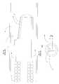
- FIG. 1 ais a cross-sectional side view of an imaging transducer assembly known in the art.
- FIG. 1 bis a cross-sectional distal end view of the prior art imaging transducer assembly of FIG. 1 a.
- FIG. 2is a cross-sectional distal end view of an imaging transducer assembly in accordance with an example embodiment of the invention.
- FIG. 3is a top perspective view of an imaging transducer assembly in accordance with an example embodiment of the invention.
- FIG. 4Ais a cross-sectional side view of an imaging transducer assembly in accordance with an example embodiment of the invention.
- FIG. 4Bis a side view of a catheter in accordance with an example embodiment of the invention.
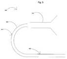
- FIG. 5is a partial cross-sectional side view of a catheter in accordance with an example embodiment of the invention.
- FIG. 1 ba cross-sectional distal end view of a prior art imaging transducer assembly 1 within the lumen of a sheath 5 , having a curvature, is shown.
- the purpose of the sheath 5is generally to isolate the transducer assembly 1 from the imaging environment.
- the sheath 5is desirably sonolucent so as not to distort the acoustic beams 60 emitted from the transducer assembly 1 .
- the width W of the beam 60remains substantially constant.
- the width W of the beam 60may be narrowed.
- FIG. 2shows a cross-sectional distal end view of an imaging transducer assembly 100 located within the lumen 150 of a sheath 105 .
- the imaging transducer assembly 100emits an acoustic beam 160 having a width W 1 .
- the sheath 105is configured to narrow the width of the beam 160 from W 1 to W 2 , as explained in detail below.
- the narrower width W 2desirably increases the resolution and precision of the resulting image.
- the refractive index, nis a constant associated with a particular material, or medium, and indicates how much the medium will refract an energy beam that reaches the surface of the medium.
- the incident mediumis the medium in which the incident energy beam is traveling
- the transmitted mediumis the medium in which the refracted energy beam is traveling. Applying these terms to FIG. 2 , the incident medium, n 1 , is the medium within the lumen 150 . This is typically a sonolucent medium, such as water or saline.
- the transmitted medium, n 2is the medium of the sheath 105 .
- a common material, for example, for the sheath 105is polyethylene (“PE”).
- the angle of incidence, ⁇ 1is measured between the incident energy beam and the normal to the surface between the incident and transmitted mediums.
- the angle of refraction, ⁇ 2is measured between the normal to the surface between the incident and transmitted mediums and the refracted energy beam.
- the angle of incidenceis angle A, between the normal 170 to the surface of the inside of the sheath 105 , exposed to the lumen 150 , and the portion 162 of the energy beam 160 traveling through the lumen 150 .
- the angle of refractionis angle B, between the same normal line 170 and the portion 164 of the beam 160 traveling through the sheath 105 .
- the sheath 105can also be viewed as the incident medium and the area 190 outside of the sheath 105 can be viewed as the refracted medium.
- angle Ccan be viewed as the angle of incidence, between the normal 180 to the surface of the outside 190 of the sheath 105 and the portion 164 of the beam 160 traveling through the sheath 105 .
- angle Dcan be viewed as the angle of refraction, between the normal 180 to the surface of the outside 190 of the sheath 105 and the portion 166 of the beam 160 traveling through the medium outside of the sheath 105 .
- the refraction occurring at the inside surface of the sheath 105 and the refraction occurring at the outside surface of the sheath 105result in a narrower beam 160 exiting the sheath 105 .
- a mediummay also be characterized by its phase velocity or sound velocity, v, which is the velocity of propagation of an energy wave, e.g., acoustic wave, traveling through the medium.
- equation (1) or (2)if the medium within the lumen 150 is viewed as the incident medium, and the sheath 105 is viewed as the transmitted medium, then if the angle of refraction, ⁇ 2 , within the sheath 105 , i.e., angle B, is increased to a value at least greater than angle A, then the acoustic beam 160 will desirably become more narrow, i.e., the value of W 2 will be smaller.
- a sheath 105 material with a higher phase velocity, v 2than the phase velocity of the medium within the lumen 150 , v 1 .
- equation (2)a higher value v 2 will result in a higher angle of refraction, ⁇ 2 , and thus, an increased angle B.
- a sheath 105 material with a higher phase velocitye.g., 2.0 mm/ ⁇ sec, will result in an increased angle B.
- angles C and Dwhere angle C is the angle of incidence within the sheath 105 and angle D is the angle of refraction outside 190 of the sheath 105 , often the transmitted medium outside 190 of the sheath 105 is blood, which typically has substantially the same phase velocity as water, i.e., 1.5 mm/ ⁇ sec. Accordingly, if the sheath 105 material has a higher phase velocity than the phase velocity of the medium outside 190 of the sheath 105 , then using equation (2), the angle of incidence, angle C, may be larger than the angle of refraction, angle D.
- the portion 166 of the beam 160 exiting the sheath 105is still narrower than the portion 162 of the beam 160 within the lumen 150 of the sheath 105 .
- a common sheath 105 materialincludes a mixture of different types of materials, e.g., different types of PE materials.
- the sheath 105 materialsmay be produced by blending certain percentages of different materials having different densities, such as REXENE®, a polyethylene having a phase velocity of approximately 2.32 mm/ ⁇ sec and a density of 0.89 g/mm, and ALATHON®, which has a phase velocity of approximately 2.25 mm/ ⁇ sec and a density of 0.92 g/mm. This may affect the phase velocity v 2 of the sheath 105 material.
- a sheath 105 materialmay include 70% REXENE® polyethylene and 30% ALATHON®.
- Another approachis to increase the thickness of the sheath 105 .
- An increased thicknessmay result in moving the normal line 180 to the outside surface of the sheath 105 closer to the center of the beam 160 , thus resulting in a narrower beam 160 .
- the thicker sheath 105may decrease the incident angle within the sheath 105 , angle C, and thus decrease the angle of refraction outside 190 of the sheath 105 , i.e., angle D.
- the resulting beam thickness W 2will desirably be smaller.
- the amount of thicknessmay depend upon the diameter of the sheath 105 and the dimensions of the imaging environment, e.g., the diameter of a blood vessel in which the transducer assembly 100 and sheath 105 is located. For a sheath 105 having a diameter of approximately 1 mm and for a blood vessel having a diameter of at least 6 mm, it may be desirable to have sheath 105 thickness of at least 0.18 mm. In addition, multiple sheath layers may be used (not shown), and further, each layer may have a higher phase velocity than its neighboring inner layer.
- the radius of curvature of the inside surface of the sheath 105may be decreased.
- the decreased radius of curvaturemay cause the angle of incidence, ⁇ 1 , i.e., angle A, to increase, which may then, using equation (1) or (2), increase the angle of refraction, ⁇ 2 , within the sheath 105 , i.e., angle B.
- a medium within the lumen 150may be selected or produced with a lower phase velocity, v 1 .
- equation (2)a medium within the lumen 150 with a lower phase velocity, v 1 , may result in a higher angle of refraction, ⁇ 2 , within the sheath 105 , i.e., angle B.
- the medium within the lumen 150is water, which typically has a phase velocity of approximately 1.5 mm/ ⁇ sec.
- Other liquids or materialsmay be used that have lower phase velocities than the phase velocity for water, such as certain types of alcohols, such as ethanol, which has a phase velocity of 1.207 mm/ ⁇ sec.
- FIG. 3a top perspective view of the imaging transducer assembly 100 is shown.
- the sheath 105has a cylindrical shape. Applying x-y-z axes, as shown, one can see that the portion 162 of the beam 160 along the x-axis is narrowed as the beam 160 exits the sheath 105 . However, by virtue of the cylindrical shape, the portion 165 of the beam 160 along the y-axis may remain substantially unchanged as the beam 160 exits the sheath 105 because of the lack of curvature along the y-axis.
- FIGSOne approach to narrowing the beam 160 along the entire perimeter of the beam 160 is shown in FIGS.
- FIG. 4A and 4Bwhich shows a cross-sectional side view of an imaging transducer assembly 100 located within the lumen of a sheath 205 having a portion of the sheath 205 that covers the assembly 100 shaped into a sphere.
- the surface area of the beam 260is reduced along its entire perimeter, including the portion 262 of the beam 260 along the x-axis and the portion 265 of the beam 260 along the y-axis.
- the guidewire 500may comprise a guidewire body 302 in the form of a flexible, elongate tubular member, having an outer wall 301 .
- the guidewire body 302may be formed of any material known in the art including nitinol hypotube, metal alloys, composite materials, plastics, braided polyimide, polyethylene, peek braids, stainless steel, or other superelastic materials.
- the length of the guidewire 500may vary depending on the application. In a preferred embodiment, the length of the guidewire 500 is between 30 cm and 300 cm.
- a catheter(not shown) may be configured to use several different diameters of guidewires 500 .
- the guidewire 500may have a diameter of 0.010, 0.014, 0.018, or 0.035 inches. Typically, the diameter of the guidewire 500 is uniform.
- a proximal portion 510 of the guidewire 500may be adapted to connect to circuitry (not shown) that processes imaging signals from the imaging transducer, such circuits well known in the art.
Landscapes
- Health & Medical Sciences (AREA)
- Life Sciences & Earth Sciences (AREA)
- Surgery (AREA)
- Nuclear Medicine, Radiotherapy & Molecular Imaging (AREA)
- Biomedical Technology (AREA)
- Veterinary Medicine (AREA)
- Pathology (AREA)
- Radiology & Medical Imaging (AREA)
- Biophysics (AREA)
- Engineering & Computer Science (AREA)
- Physics & Mathematics (AREA)
- Heart & Thoracic Surgery (AREA)
- Medical Informatics (AREA)
- Molecular Biology (AREA)
- Animal Behavior & Ethology (AREA)
- General Health & Medical Sciences (AREA)
- Public Health (AREA)
- Optics & Photonics (AREA)
- Ultra Sonic Daignosis Equipment (AREA)
Abstract
Description
n1sin Θ1=n2sin Θ2wherein, (1)
- n1=the refractive index of the incident medium,
- Θ1=the angle of the incidence,
- n2=the refractive index in the transmitted medium, and
- Θ2=the angle of refraction.
v2sin Θ1=v1sin Θ2wherein, (2)
- v2=the phase velocity of the transmitted medium,
- Θ1=the angle of the incidence,
- v1=the phase velocity of the incident medium, and
- Θ2=the angle of refraction.
Claims (17)
Priority Applications (5)
| Application Number | Priority Date | Filing Date | Title |
|---|---|---|---|
| US10/443,592US7909766B2 (en) | 2003-05-21 | 2003-05-21 | Systems and methods for improving the imaging resolution of an imaging transducer |
| PCT/US2004/012013WO2004105617A1 (en) | 2003-05-21 | 2004-04-16 | Systems and methods for improving the resolution of an imaging transducer |
| JP2006532429AJP4551896B2 (en) | 2003-05-21 | 2004-04-16 | System and method for increasing the resolution of an imaging transducer |
| EP04750314AEP1624806A1 (en) | 2003-05-21 | 2004-04-16 | Systems and methods for improving the resolution of an imaging transducer |
| CA002523381ACA2523381A1 (en) | 2003-05-21 | 2004-04-16 | Systems and methods for improving the resolution of an imaging transducer |
Applications Claiming Priority (1)
| Application Number | Priority Date | Filing Date | Title |
|---|---|---|---|
| US10/443,592US7909766B2 (en) | 2003-05-21 | 2003-05-21 | Systems and methods for improving the imaging resolution of an imaging transducer |
Publications (2)
| Publication Number | Publication Date |
|---|---|
| US20040236205A1 US20040236205A1 (en) | 2004-11-25 |
| US7909766B2true US7909766B2 (en) | 2011-03-22 |
Family
ID=33450453
Family Applications (1)
| Application Number | Title | Priority Date | Filing Date |
|---|---|---|---|
| US10/443,592Expired - Fee RelatedUS7909766B2 (en) | 2003-05-21 | 2003-05-21 | Systems and methods for improving the imaging resolution of an imaging transducer |
Country Status (5)
| Country | Link |
|---|---|
| US (1) | US7909766B2 (en) |
| EP (1) | EP1624806A1 (en) |
| JP (1) | JP4551896B2 (en) |
| CA (1) | CA2523381A1 (en) |
| WO (1) | WO2004105617A1 (en) |
Citations (72)
| Publication number | Priority date | Publication date | Assignee | Title |
|---|---|---|---|---|
| US3005452A (en)* | 1957-12-23 | 1961-10-24 | Louis K Pitman | Nasolaryngoscope |
| US4349032A (en) | 1978-12-15 | 1982-09-14 | Olympus Optical Co., Ltd. | Endoscope with an ultrasonic probe |
| US4387720A (en) | 1980-12-29 | 1983-06-14 | Hewlett-Packard Company | Transducer acoustic lens |
| US4674515A (en) | 1984-10-26 | 1987-06-23 | Olympus Optical Co., Ltd. | Ultrasonic endoscope |
| US4794931A (en) | 1986-02-28 | 1989-01-03 | Cardiovascular Imaging Systems, Inc. | Catheter apparatus, system and method for intravascular two-dimensional ultrasonography |
| US4815470A (en)* | 1987-11-13 | 1989-03-28 | Advanced Diagnostic Medical Systems, Inc. | Inflatable sheath for ultrasound probe |
| US4821731A (en) | 1986-04-25 | 1989-04-18 | Intra-Sonix, Inc. | Acoustic image system and method |
| US4834102A (en)* | 1988-02-25 | 1989-05-30 | Jack Schwarzchild | Endoscope for transesophageal echocardiography |
| US4951677A (en) | 1988-03-21 | 1990-08-28 | Prutech Research And Development Partnership Ii | Acoustic imaging catheter and the like |
| JPH02277445A (en) | 1989-01-23 | 1990-11-14 | Olympus Optical Co Ltd | Probe for ultrasonic diagnosis |
| US5000185A (en) | 1986-02-28 | 1991-03-19 | Cardiovascular Imaging Systems, Inc. | Method for intravascular two-dimensional ultrasonography and recanalization |
| US5024234A (en) | 1989-10-17 | 1991-06-18 | Cardiovascular Imaging Systems, Inc. | Ultrasonic imaging catheter with guidewire channel |
| US5054492A (en) | 1990-12-17 | 1991-10-08 | Cardiovascular Imaging Systems, Inc. | Ultrasonic imaging catheter having rotational image correlation |
| US5078702A (en)* | 1988-03-25 | 1992-01-07 | Baxter International Inc. | Soft tip catheters |
| US5115814A (en) | 1989-08-18 | 1992-05-26 | Intertherapy, Inc. | Intravascular ultrasonic imaging probe and methods of using same |
| US5199437A (en)* | 1991-09-09 | 1993-04-06 | Sensor Electronics, Inc. | Ultrasonic imager |
| US5203338A (en) | 1990-12-17 | 1993-04-20 | Cardiovascular Imaging Systems, Inc. | Vascular catheter having low-profile distal end |
| US5243988A (en) | 1991-03-13 | 1993-09-14 | Scimed Life Systems, Inc. | Intravascular imaging apparatus and methods for use and manufacture |
| US5249580A (en)* | 1991-10-08 | 1993-10-05 | Griffith James M | Method for ultrasound imaging |
| EP0580304A1 (en) | 1992-07-22 | 1994-01-26 | Hewlett-Packard Company | Intracavity ultrasound diagnostic probe using fiber acoustic waveguides |
| US5305755A (en)* | 1991-03-12 | 1994-04-26 | Fujitsu Limited | Ultrasonic probe, having transducer array capable of turning around its aperture axis and having a convex lens comprising a viscous resin |
| US5368035A (en) | 1988-03-21 | 1994-11-29 | Boston Scientific Corporation | Ultrasound imaging guidewire |
| US5400789A (en)* | 1991-10-08 | 1995-03-28 | Griffith; James M. | Sheath for guide wire probe |
| JPH07111996A (en) | 1993-10-18 | 1995-05-02 | Olympus Optical Co Ltd | Ultrasonic endoscope |
| US5438997A (en)* | 1991-03-13 | 1995-08-08 | Sieben; Wayne | Intravascular imaging apparatus and methods for use and manufacture |
| US5509917A (en) | 1994-06-28 | 1996-04-23 | Ceramoptec Industries, Inc. | Lensed caps for radial medical laser delivery devices |
| US5571114A (en)* | 1994-07-13 | 1996-11-05 | Devanaboyina; Udaya-Sankar | Mechanism to advance or withdraw objects in lumens or cavities of mammals |
| JPH09117452A (en) | 1995-09-25 | 1997-05-06 | Hewlett Packard Co <Hp> | Device with aspherical surface compensation and method to focus ultrasonic wave |
| US5655537A (en)* | 1994-11-30 | 1997-08-12 | Boston Scientific Corporation | Acoustic imaging and doppler catheters and guidewires |
| JPH1071149A (en) | 1996-08-29 | 1998-03-17 | Toshiba Corp | Ultrasonic probe |
| JPH10248850A (en) | 1997-03-11 | 1998-09-22 | Olympus Optical Co Ltd | Ultrasonic probe |
| US5820561A (en) | 1996-07-30 | 1998-10-13 | Vingmed Sound A/S | Analysis and measurement of temporal tissue velocity information |
| US5827313A (en) | 1996-09-27 | 1998-10-27 | Boston Scientific Corporation | Device for controlled longitudinal movement of an operative element within a catheter sheath and method |
| US5873830A (en) | 1997-08-22 | 1999-02-23 | Acuson Corporation | Ultrasound imaging system and method for improving resolution and operation |
| US5879305A (en) | 1995-06-06 | 1999-03-09 | Cardiovascular Imaging Systems, Inc. | Rotational correlation of intravascular ultrasound image with guide catheter position |
| US5897504A (en)* | 1997-12-12 | 1999-04-27 | The Whitaker Corporation | Ultrasound imaging probe assembly |
| US5902242A (en) | 1998-01-22 | 1999-05-11 | Acuson Corporation | System and method for forming a combined ultrasonic image |
| US5921934A (en) | 1997-11-25 | 1999-07-13 | Scimed Life Systems, Inc. | Methods and apparatus for non-uniform rotation distortion detection in an intravascular ultrasound imaging system |
| US5931788A (en) | 1997-12-05 | 1999-08-03 | Keen; Richard R. | Method and apparatus for imaging internal organs and vascular structures through the gastrointestinal wall |
| US5979093A (en) | 1997-12-12 | 1999-11-09 | Everbrite, Inc. | Changeable information scroll sign module |
| US5980451A (en)* | 1984-10-23 | 1999-11-09 | Sherwood Services Ag | Disposable speculum with membrane bonding ring |
| US5984871A (en) | 1997-08-12 | 1999-11-16 | Boston Scientific Technologies, Inc. | Ultrasound transducer with extended focus |
| US5993390A (en) | 1998-09-18 | 1999-11-30 | Hewlett- Packard Company | Segmented 3-D cardiac ultrasound imaging method and apparatus |
| US6014473A (en) | 1996-02-29 | 2000-01-11 | Acuson Corporation | Multiple ultrasound image registration system, method and transducer |
| US6019724A (en) | 1995-02-22 | 2000-02-01 | Gronningsaeter; Aage | Method for ultrasound guidance during clinical procedures |
| US6056691A (en) | 1998-06-24 | 2000-05-02 | Ecton, Inc. | System for collecting ultrasound imaging data at an adjustable collection image frame rate |
| US6078831A (en) | 1997-09-29 | 2000-06-20 | Scimed Life Systems, Inc. | Intravascular imaging guidewire |
| US6123670A (en) | 1998-12-15 | 2000-09-26 | General Electric Company | Ultrasound imaging with optimal image quality in region of interest |
| US6139499A (en) | 1999-02-22 | 2000-10-31 | Wilk; Peter J. | Ultrasonic medical system and associated method |
| US6165127A (en) | 1988-03-21 | 2000-12-26 | Boston Scientific Corporation | Acoustic imaging catheter and the like |
| US6171250B1 (en) | 1997-09-29 | 2001-01-09 | Boston Scientific Corporation | Ultrasound imaging guidewire with static central core and tip |
| US6190320B1 (en) | 1998-09-29 | 2001-02-20 | U.S. Philips Corporation | Method for the processing of medical ultrasound images of bony structures, and method and device for computer-assisted surgery |
| US6261234B1 (en) | 1998-05-07 | 2001-07-17 | Diasonics Ultrasound, Inc. | Method and apparatus for ultrasound imaging with biplane instrument guidance |
| US6261246B1 (en) | 1997-09-29 | 2001-07-17 | Scimed Life Systems, Inc. | Intravascular imaging guidewire |
| US6283921B1 (en)* | 1996-07-11 | 2001-09-04 | Intravascular Research Limited | Ultrasonic visualization and catheters therefor |
| US20010020126A1 (en)* | 1996-10-28 | 2001-09-06 | David K. Swanson | Systems and methods for visualizing tissue during diagnostic or therapeutic procedures |
| US6287261B1 (en)* | 1999-07-21 | 2001-09-11 | Scimed Life Systems, Inc. | Focused ultrasound transducers and systems |
| US6309379B1 (en)* | 1991-05-23 | 2001-10-30 | Lloyd K. Willard | Sheath for selective delivery of multiple intravascular devices and methods of use thereof |
| US20010039058A1 (en) | 1999-05-14 | 2001-11-08 | Iheme Mordi I. | Fluid transfer device |
| US6419639B2 (en)* | 1999-08-05 | 2002-07-16 | National Institute Of Health | Laparoscopic SAC holder assembly |
| US6428477B1 (en) | 2000-03-10 | 2002-08-06 | Koninklijke Philips Electronics, N.V. | Delivery of theraputic ultrasound by two dimensional ultrasound array |
| US6442289B1 (en) | 1999-06-30 | 2002-08-27 | Koninklijke Philips Electronics N.V. | Extended field of view ultrasonic diagnostic imaging |
| US6450964B1 (en) | 2000-09-05 | 2002-09-17 | Advanced Cardiovascular Systems, Inc. | Imaging apparatus and method |
| US6491636B2 (en) | 2000-12-07 | 2002-12-10 | Koninklijke Philips Electronics N.V. | Automated border detection in ultrasonic diagnostic images |
| US6511426B1 (en) | 1998-06-02 | 2003-01-28 | Acuson Corporation | Medical diagnostic ultrasound system and method for versatile processing |
| US6516215B1 (en) | 2000-11-20 | 2003-02-04 | Atl Ultrasound, Inc. | Diagnostic ultrasound imaging system having display configured to optimally display ultrasound images |
| US6520915B1 (en) | 2000-01-28 | 2003-02-18 | U-Systems, Inc. | Ultrasound imaging system with intrinsic doppler capability |
| US6520912B1 (en) | 2000-11-09 | 2003-02-18 | Acuson Corporation | Method and system for displaying medical data such as a diagnostic medical ultrasound image at an automatically-selected display resolution |
| US6524251B2 (en)* | 1999-10-05 | 2003-02-25 | Omnisonics Medical Technologies, Inc. | Ultrasonic device for tissue ablation and sheath for use therewith |
| US6537217B1 (en) | 2001-08-24 | 2003-03-25 | Ge Medical Systems Global Technology Company, Llc | Method and apparatus for improved spatial and temporal resolution in ultrasound imaging |
| US6540681B1 (en) | 2000-11-24 | 2003-04-01 | U-Systems, Inc. | Extended view ultrasound imaging system |
| US20030233115A1 (en)* | 2002-04-25 | 2003-12-18 | Eversull Christian Scott | Expandable guide sheath and apparatus and methods using such sheaths |
Family Cites Families (1)
| Publication number | Priority date | Publication date | Assignee | Title |
|---|---|---|---|---|
| US5442289A (en)* | 1989-07-31 | 1995-08-15 | Biomagnetic Technologies, Inc. | Biomagnetometer having flexible sensor |
- 2003
- 2003-05-21USUS10/443,592patent/US7909766B2/ennot_activeExpired - Fee Related
- 2004
- 2004-04-16CACA002523381Apatent/CA2523381A1/ennot_activeAbandoned
- 2004-04-16JPJP2006532429Apatent/JP4551896B2/ennot_activeExpired - Lifetime
- 2004-04-16EPEP04750314Apatent/EP1624806A1/ennot_activeWithdrawn
- 2004-04-16WOPCT/US2004/012013patent/WO2004105617A1/enactiveApplication Filing
Patent Citations (81)
| Publication number | Priority date | Publication date | Assignee | Title |
|---|---|---|---|---|
| US3005452A (en)* | 1957-12-23 | 1961-10-24 | Louis K Pitman | Nasolaryngoscope |
| US4349032A (en) | 1978-12-15 | 1982-09-14 | Olympus Optical Co., Ltd. | Endoscope with an ultrasonic probe |
| US4387720A (en) | 1980-12-29 | 1983-06-14 | Hewlett-Packard Company | Transducer acoustic lens |
| US5980451A (en)* | 1984-10-23 | 1999-11-09 | Sherwood Services Ag | Disposable speculum with membrane bonding ring |
| US4674515A (en) | 1984-10-26 | 1987-06-23 | Olympus Optical Co., Ltd. | Ultrasonic endoscope |
| US5000185A (en) | 1986-02-28 | 1991-03-19 | Cardiovascular Imaging Systems, Inc. | Method for intravascular two-dimensional ultrasonography and recanalization |
| US5902245A (en) | 1986-02-28 | 1999-05-11 | Cardiovascular Imaging Systems, Inc. | Method and apparatus for intravascular ultrasonography |
| US4794931A (en) | 1986-02-28 | 1989-01-03 | Cardiovascular Imaging Systems, Inc. | Catheter apparatus, system and method for intravascular two-dimensional ultrasonography |
| US4821731A (en) | 1986-04-25 | 1989-04-18 | Intra-Sonix, Inc. | Acoustic image system and method |
| US4815470A (en)* | 1987-11-13 | 1989-03-28 | Advanced Diagnostic Medical Systems, Inc. | Inflatable sheath for ultrasound probe |
| US4834102A (en)* | 1988-02-25 | 1989-05-30 | Jack Schwarzchild | Endoscope for transesophageal echocardiography |
| US6165127A (en) | 1988-03-21 | 2000-12-26 | Boston Scientific Corporation | Acoustic imaging catheter and the like |
| US4951677A (en) | 1988-03-21 | 1990-08-28 | Prutech Research And Development Partnership Ii | Acoustic imaging catheter and the like |
| US5368035A (en) | 1988-03-21 | 1994-11-29 | Boston Scientific Corporation | Ultrasound imaging guidewire |
| US6364840B1 (en) | 1988-03-21 | 2002-04-02 | Boston Scientific Corporation | Acoustic imaging catheter and the like |
| US5078702A (en)* | 1988-03-25 | 1992-01-07 | Baxter International Inc. | Soft tip catheters |
| JPH02277445A (en) | 1989-01-23 | 1990-11-14 | Olympus Optical Co Ltd | Probe for ultrasonic diagnosis |
| US5115814A (en) | 1989-08-18 | 1992-05-26 | Intertherapy, Inc. | Intravascular ultrasonic imaging probe and methods of using same |
| US5024234A (en) | 1989-10-17 | 1991-06-18 | Cardiovascular Imaging Systems, Inc. | Ultrasonic imaging catheter with guidewire channel |
| US5203338A (en) | 1990-12-17 | 1993-04-20 | Cardiovascular Imaging Systems, Inc. | Vascular catheter having low-profile distal end |
| US5054492A (en) | 1990-12-17 | 1991-10-08 | Cardiovascular Imaging Systems, Inc. | Ultrasonic imaging catheter having rotational image correlation |
| US5305755A (en)* | 1991-03-12 | 1994-04-26 | Fujitsu Limited | Ultrasonic probe, having transducer array capable of turning around its aperture axis and having a convex lens comprising a viscous resin |
| US5243988A (en) | 1991-03-13 | 1993-09-14 | Scimed Life Systems, Inc. | Intravascular imaging apparatus and methods for use and manufacture |
| US5438997A (en)* | 1991-03-13 | 1995-08-08 | Sieben; Wayne | Intravascular imaging apparatus and methods for use and manufacture |
| US6309379B1 (en)* | 1991-05-23 | 2001-10-30 | Lloyd K. Willard | Sheath for selective delivery of multiple intravascular devices and methods of use thereof |
| US5199437A (en)* | 1991-09-09 | 1993-04-06 | Sensor Electronics, Inc. | Ultrasonic imager |
| US5400789A (en)* | 1991-10-08 | 1995-03-28 | Griffith; James M. | Sheath for guide wire probe |
| US5249580A (en)* | 1991-10-08 | 1993-10-05 | Griffith James M | Method for ultrasound imaging |
| EP0580304A1 (en) | 1992-07-22 | 1994-01-26 | Hewlett-Packard Company | Intracavity ultrasound diagnostic probe using fiber acoustic waveguides |
| JPH07111996A (en) | 1993-10-18 | 1995-05-02 | Olympus Optical Co Ltd | Ultrasonic endoscope |
| US5509917A (en) | 1994-06-28 | 1996-04-23 | Ceramoptec Industries, Inc. | Lensed caps for radial medical laser delivery devices |
| US5571114A (en)* | 1994-07-13 | 1996-11-05 | Devanaboyina; Udaya-Sankar | Mechanism to advance or withdraw objects in lumens or cavities of mammals |
| US5655537A (en)* | 1994-11-30 | 1997-08-12 | Boston Scientific Corporation | Acoustic imaging and doppler catheters and guidewires |
| US6019724A (en) | 1995-02-22 | 2000-02-01 | Gronningsaeter; Aage | Method for ultrasound guidance during clinical procedures |
| US5879305A (en) | 1995-06-06 | 1999-03-09 | Cardiovascular Imaging Systems, Inc. | Rotational correlation of intravascular ultrasound image with guide catheter position |
| JPH09117452A (en) | 1995-09-25 | 1997-05-06 | Hewlett Packard Co <Hp> | Device with aspherical surface compensation and method to focus ultrasonic wave |
| US5640961A (en)* | 1995-09-25 | 1997-06-24 | Hewlett-Packard Company | Device with aspherical compensation for focusing ultrasound |
| US6360027B1 (en) | 1996-02-29 | 2002-03-19 | Acuson Corporation | Multiple ultrasound image registration system, method and transducer |
| US6014473A (en) | 1996-02-29 | 2000-01-11 | Acuson Corporation | Multiple ultrasound image registration system, method and transducer |
| US6283921B1 (en)* | 1996-07-11 | 2001-09-04 | Intravascular Research Limited | Ultrasonic visualization and catheters therefor |
| US5820561A (en) | 1996-07-30 | 1998-10-13 | Vingmed Sound A/S | Analysis and measurement of temporal tissue velocity information |
| JPH1071149A (en) | 1996-08-29 | 1998-03-17 | Toshiba Corp | Ultrasonic probe |
| US5827313A (en) | 1996-09-27 | 1998-10-27 | Boston Scientific Corporation | Device for controlled longitudinal movement of an operative element within a catheter sheath and method |
| US20010020126A1 (en)* | 1996-10-28 | 2001-09-06 | David K. Swanson | Systems and methods for visualizing tissue during diagnostic or therapeutic procedures |
| JPH10248850A (en) | 1997-03-11 | 1998-09-22 | Olympus Optical Co Ltd | Ultrasonic probe |
| US5984871A (en) | 1997-08-12 | 1999-11-16 | Boston Scientific Technologies, Inc. | Ultrasound transducer with extended focus |
| US5873830A (en) | 1997-08-22 | 1999-02-23 | Acuson Corporation | Ultrasound imaging system and method for improving resolution and operation |
| US6261246B1 (en) | 1997-09-29 | 2001-07-17 | Scimed Life Systems, Inc. | Intravascular imaging guidewire |
| US6529760B2 (en) | 1997-09-29 | 2003-03-04 | Scimed Life Systems, Inc. | Intravascular imaging guidewire |
| US6078831A (en) | 1997-09-29 | 2000-06-20 | Scimed Life Systems, Inc. | Intravascular imaging guidewire |
| US6171250B1 (en) | 1997-09-29 | 2001-01-09 | Boston Scientific Corporation | Ultrasound imaging guidewire with static central core and tip |
| US6248076B1 (en) | 1997-09-29 | 2001-06-19 | Boston Scientific Corporation | Ultrasound imaging guidewire with static central core and tip |
| US6120455A (en) | 1997-11-25 | 2000-09-19 | Scimed Life Systems, Inc. | Methods and apparatus for non-uniform rotation distortion detection in an intravascular ultrasound imaging system |
| US5921934A (en) | 1997-11-25 | 1999-07-13 | Scimed Life Systems, Inc. | Methods and apparatus for non-uniform rotation distortion detection in an intravascular ultrasound imaging system |
| US6267727B1 (en) | 1997-11-25 | 2001-07-31 | Scimed Life Systems, Inc. | Methods and apparatus for non-uniform rotation distortion detection in an intravascular ultrasound imaging system |
| US5931788A (en) | 1997-12-05 | 1999-08-03 | Keen; Richard R. | Method and apparatus for imaging internal organs and vascular structures through the gastrointestinal wall |
| US5897504A (en)* | 1997-12-12 | 1999-04-27 | The Whitaker Corporation | Ultrasound imaging probe assembly |
| US5979093A (en) | 1997-12-12 | 1999-11-09 | Everbrite, Inc. | Changeable information scroll sign module |
| US5902242A (en) | 1998-01-22 | 1999-05-11 | Acuson Corporation | System and method for forming a combined ultrasonic image |
| US6261234B1 (en) | 1998-05-07 | 2001-07-17 | Diasonics Ultrasound, Inc. | Method and apparatus for ultrasound imaging with biplane instrument guidance |
| US6511426B1 (en) | 1998-06-02 | 2003-01-28 | Acuson Corporation | Medical diagnostic ultrasound system and method for versatile processing |
| US6056691A (en) | 1998-06-24 | 2000-05-02 | Ecton, Inc. | System for collecting ultrasound imaging data at an adjustable collection image frame rate |
| US5993390A (en) | 1998-09-18 | 1999-11-30 | Hewlett- Packard Company | Segmented 3-D cardiac ultrasound imaging method and apparatus |
| US6190320B1 (en) | 1998-09-29 | 2001-02-20 | U.S. Philips Corporation | Method for the processing of medical ultrasound images of bony structures, and method and device for computer-assisted surgery |
| US6123670A (en) | 1998-12-15 | 2000-09-26 | General Electric Company | Ultrasound imaging with optimal image quality in region of interest |
| US6139499A (en) | 1999-02-22 | 2000-10-31 | Wilk; Peter J. | Ultrasonic medical system and associated method |
| US20010039058A1 (en) | 1999-05-14 | 2001-11-08 | Iheme Mordi I. | Fluid transfer device |
| US20010041336A1 (en)* | 1999-05-14 | 2001-11-15 | Anderson Bruce W. | Collection device and method for removing a fluid substance from the same |
| US6442289B1 (en) | 1999-06-30 | 2002-08-27 | Koninklijke Philips Electronics N.V. | Extended field of view ultrasonic diagnostic imaging |
| US6287261B1 (en)* | 1999-07-21 | 2001-09-11 | Scimed Life Systems, Inc. | Focused ultrasound transducers and systems |
| US6419639B2 (en)* | 1999-08-05 | 2002-07-16 | National Institute Of Health | Laparoscopic SAC holder assembly |
| US6524251B2 (en)* | 1999-10-05 | 2003-02-25 | Omnisonics Medical Technologies, Inc. | Ultrasonic device for tissue ablation and sheath for use therewith |
| US6520915B1 (en) | 2000-01-28 | 2003-02-18 | U-Systems, Inc. | Ultrasound imaging system with intrinsic doppler capability |
| US6428477B1 (en) | 2000-03-10 | 2002-08-06 | Koninklijke Philips Electronics, N.V. | Delivery of theraputic ultrasound by two dimensional ultrasound array |
| US6450964B1 (en) | 2000-09-05 | 2002-09-17 | Advanced Cardiovascular Systems, Inc. | Imaging apparatus and method |
| US6520912B1 (en) | 2000-11-09 | 2003-02-18 | Acuson Corporation | Method and system for displaying medical data such as a diagnostic medical ultrasound image at an automatically-selected display resolution |
| US6516215B1 (en) | 2000-11-20 | 2003-02-04 | Atl Ultrasound, Inc. | Diagnostic ultrasound imaging system having display configured to optimally display ultrasound images |
| US6540681B1 (en) | 2000-11-24 | 2003-04-01 | U-Systems, Inc. | Extended view ultrasound imaging system |
| US6491636B2 (en) | 2000-12-07 | 2002-12-10 | Koninklijke Philips Electronics N.V. | Automated border detection in ultrasonic diagnostic images |
| US6537217B1 (en) | 2001-08-24 | 2003-03-25 | Ge Medical Systems Global Technology Company, Llc | Method and apparatus for improved spatial and temporal resolution in ultrasound imaging |
| US20030233115A1 (en)* | 2002-04-25 | 2003-12-18 | Eversull Christian Scott | Expandable guide sheath and apparatus and methods using such sheaths |
Non-Patent Citations (5)
| Title |
|---|
| "HDPE (High-Density Polyethylene)". Dec. 2001. http://web.archive.org/web/20011212210839/http://www.jbcplastic.com/hdpe.htm.* |
| C.L. de Korte, et al, "High Resolution IVUS Elastography in Patients", Proceedings of the IEEE Ultrasonics Symposium, 2000, pp. 1767-1770, The Netherlands. |
| Didier Vray, et al., "Synthetic Aperture-Based Beam Compression for Intravascular Ultrasound Imaging", IEEE Transactions on Ultrasonics, Ferroelectrics, and Frequency Control, Jan. 2001, pp. 189-201, vol. 48, No. 1, USA. |
| Selfride, Alan. "US data for liquids." Jun. 27, 2002. Sep. 14, 2010. http://web.archive.org/web/20020627114512/http://signal-processing.com/tech/us-data-liquid.htm.* |
| Yao Wang, et al., "Optimizing the Beam Pattern of a Forward-Viewing Ring-Annular Ultrasound Array for Intravascular Imaging", Dec. 2002, pp. 1652-1664, vol. 49, No. 12, USA. |
Also Published As
| Publication number | Publication date |
|---|---|
| CA2523381A1 (en) | 2004-12-09 |
| JP2007500052A (en) | 2007-01-11 |
| US20040236205A1 (en) | 2004-11-25 |
| JP4551896B2 (en) | 2010-09-29 |
| WO2004105617A1 (en) | 2004-12-09 |
| EP1624806A1 (en) | 2006-02-15 |
Similar Documents
| Publication | Publication Date | Title |
|---|---|---|
| US20240285253A1 (en) | Intracardiac echocardiography (ice) catheter tip assembly | |
| US8303510B2 (en) | Medical imaging device having a forward looking flow detector | |
| US5682897A (en) | Guidewire with imaging capability | |
| US12076184B2 (en) | Pullwire crown and crown sleeve for catheter assembly | |
| EP0591175B1 (en) | Guidewire with imaging capability | |
| US20180344283A1 (en) | Method for focused acoustic computed tomography (fact) | |
| US5640961A (en) | Device with aspherical compensation for focusing ultrasound | |
| US12232908B2 (en) | Lined variable braided differential durometer multi-lumen shaft with a cross-shaped inner profile | |
| WO2007005710A2 (en) | Concave phased array imaging catheter | |
| JP7199415B2 (en) | Intraluminal imager using multiple center frequencies | |
| US20110144502A1 (en) | Imaging guidewire | |
| CN221511882U (en) | Integrated optical and ultrasonic imaging combined probe | |
| US5509418A (en) | Ultrasound diagnostic probe having acoustically driven turbin | |
| CN213309872U (en) | Optical and acoustic combined probe | |
| US7909766B2 (en) | Systems and methods for improving the imaging resolution of an imaging transducer | |
| WO2019038073A1 (en) | Adjustable flexibility/stiffness intraluminal device | |
| WO2023092725A1 (en) | Catheter sheath and imaging apparatus | |
| Burrell et al. | Angioplasty under ultrasound? |
Legal Events
| Date | Code | Title | Description |
|---|---|---|---|
| AS | Assignment | Owner name:SCIMED LIFE SYSTEMS, INC., MINNESOTA Free format text:ASSIGNMENT OF ASSIGNORS INTEREST;ASSIGNORS:LEE, WARREN;YUAN, JIAN;REEL/FRAME:014483/0447;SIGNING DATES FROM 20030814 TO 20030825 Owner name:SCIMED LIFE SYSTEMS, INC., MINNESOTA Free format text:ASSIGNMENT OF ASSIGNORS INTEREST;ASSIGNORS:LEE, WARREN;YUAN, JIAN;SIGNING DATES FROM 20030814 TO 20030825;REEL/FRAME:014483/0447 | |
| AS | Assignment | Owner name:BOSTON SCIENTIFIC SCIMED, INC., MINNESOTA Free format text:CHANGE OF NAME;ASSIGNOR:SCIMED LIFE SYSTEMS, INC.;REEL/FRAME:018505/0868 Effective date:20050101 Owner name:BOSTON SCIENTIFIC SCIMED, INC.,MINNESOTA Free format text:CHANGE OF NAME;ASSIGNOR:SCIMED LIFE SYSTEMS, INC.;REEL/FRAME:018505/0868 Effective date:20050101 | |
| STCF | Information on status: patent grant | Free format text:PATENTED CASE | |
| FPAY | Fee payment | Year of fee payment:4 | |
| MAFP | Maintenance fee payment | Free format text:PAYMENT OF MAINTENANCE FEE, 8TH YEAR, LARGE ENTITY (ORIGINAL EVENT CODE: M1552); ENTITY STATUS OF PATENT OWNER: LARGE ENTITY Year of fee payment:8 | |
| FEPP | Fee payment procedure | Free format text:MAINTENANCE FEE REMINDER MAILED (ORIGINAL EVENT CODE: REM.); ENTITY STATUS OF PATENT OWNER: LARGE ENTITY | |
| LAPS | Lapse for failure to pay maintenance fees | Free format text:PATENT EXPIRED FOR FAILURE TO PAY MAINTENANCE FEES (ORIGINAL EVENT CODE: EXP.); ENTITY STATUS OF PATENT OWNER: LARGE ENTITY | |
| STCH | Information on status: patent discontinuation | Free format text:PATENT EXPIRED DUE TO NONPAYMENT OF MAINTENANCE FEES UNDER 37 CFR 1.362 | |
| FP | Lapsed due to failure to pay maintenance fee | Effective date:20230322 |