US7909576B1 - Fastening device for rotor blade component - Google Patents
Fastening device for rotor blade componentDownload PDFInfo
- Publication number
- US7909576B1 US7909576B1US12/822,626US82262610AUS7909576B1US 7909576 B1US7909576 B1US 7909576B1US 82262610 AUS82262610 AUS 82262610AUS 7909576 B1US7909576 B1US 7909576B1
- Authority
- US
- United States
- Prior art keywords
- rotor blade
- button
- perimeter
- blade assembly
- mating groove
- Prior art date
- Legal status (The legal status is an assumption and is not a legal conclusion. Google has not performed a legal analysis and makes no representation as to the accuracy of the status listed.)
- Expired - Fee Related
Links
Images


Classifications
- F—MECHANICAL ENGINEERING; LIGHTING; HEATING; WEAPONS; BLASTING
- F03—MACHINES OR ENGINES FOR LIQUIDS; WIND, SPRING, OR WEIGHT MOTORS; PRODUCING MECHANICAL POWER OR A REACTIVE PROPULSIVE THRUST, NOT OTHERWISE PROVIDED FOR
- F03D—WIND MOTORS
- F03D1/00—Wind motors with rotation axis substantially parallel to the air flow entering the rotor
- F03D1/06—Rotors
- F03D1/065—Rotors characterised by their construction elements
- F03D1/0675—Rotors characterised by their construction elements of the blades
- F—MECHANICAL ENGINEERING; LIGHTING; HEATING; WEAPONS; BLASTING
- F03—MACHINES OR ENGINES FOR LIQUIDS; WIND, SPRING, OR WEIGHT MOTORS; PRODUCING MECHANICAL POWER OR A REACTIVE PROPULSIVE THRUST, NOT OTHERWISE PROVIDED FOR
- F03D—WIND MOTORS
- F03D80/00—Details, components or accessories not provided for in groups F03D1/00 - F03D17/00
- F03D80/30—Lightning protection
- F—MECHANICAL ENGINEERING; LIGHTING; HEATING; WEAPONS; BLASTING
- F05—INDEXING SCHEMES RELATING TO ENGINES OR PUMPS IN VARIOUS SUBCLASSES OF CLASSES F01-F04
- F05B—INDEXING SCHEME RELATING TO WIND, SPRING, WEIGHT, INERTIA OR LIKE MOTORS, TO MACHINES OR ENGINES FOR LIQUIDS COVERED BY SUBCLASSES F03B, F03D AND F03G
- F05B2240/00—Components
- F05B2240/20—Rotors
- F05B2240/30—Characteristics of rotor blades, i.e. of any element transforming dynamic fluid energy to or from rotational energy and being attached to a rotor
- F05B2240/32—Characteristics of rotor blades, i.e. of any element transforming dynamic fluid energy to or from rotational energy and being attached to a rotor with roughened surface
- F—MECHANICAL ENGINEERING; LIGHTING; HEATING; WEAPONS; BLASTING
- F05—INDEXING SCHEMES RELATING TO ENGINES OR PUMPS IN VARIOUS SUBCLASSES OF CLASSES F01-F04
- F05B—INDEXING SCHEME RELATING TO WIND, SPRING, WEIGHT, INERTIA OR LIKE MOTORS, TO MACHINES OR ENGINES FOR LIQUIDS COVERED BY SUBCLASSES F03B, F03D AND F03G
- F05B2250/00—Geometry
- F05B2250/10—Geometry two-dimensional
- F05B2250/18—Geometry two-dimensional patterned
- F05B2250/183—Geometry two-dimensional patterned zigzag
- F—MECHANICAL ENGINEERING; LIGHTING; HEATING; WEAPONS; BLASTING
- F05—INDEXING SCHEMES RELATING TO ENGINES OR PUMPS IN VARIOUS SUBCLASSES OF CLASSES F01-F04
- F05B—INDEXING SCHEME RELATING TO WIND, SPRING, WEIGHT, INERTIA OR LIKE MOTORS, TO MACHINES OR ENGINES FOR LIQUIDS COVERED BY SUBCLASSES F03B, F03D AND F03G
- F05B2260/00—Function
- F05B2260/30—Retaining components in desired mutual position
- F—MECHANICAL ENGINEERING; LIGHTING; HEATING; WEAPONS; BLASTING
- F05—INDEXING SCHEMES RELATING TO ENGINES OR PUMPS IN VARIOUS SUBCLASSES OF CLASSES F01-F04
- F05B—INDEXING SCHEME RELATING TO WIND, SPRING, WEIGHT, INERTIA OR LIKE MOTORS, TO MACHINES OR ENGINES FOR LIQUIDS COVERED BY SUBCLASSES F03B, F03D AND F03G
- F05B2260/00—Function
- F05B2260/96—Preventing, counteracting or reducing vibration or noise
- Y—GENERAL TAGGING OF NEW TECHNOLOGICAL DEVELOPMENTS; GENERAL TAGGING OF CROSS-SECTIONAL TECHNOLOGIES SPANNING OVER SEVERAL SECTIONS OF THE IPC; TECHNICAL SUBJECTS COVERED BY FORMER USPC CROSS-REFERENCE ART COLLECTIONS [XRACs] AND DIGESTS
- Y02—TECHNOLOGIES OR APPLICATIONS FOR MITIGATION OR ADAPTATION AGAINST CLIMATE CHANGE
- Y02E—REDUCTION OF GREENHOUSE GAS [GHG] EMISSIONS, RELATED TO ENERGY GENERATION, TRANSMISSION OR DISTRIBUTION
- Y02E10/00—Energy generation through renewable energy sources
- Y02E10/70—Wind energy
- Y02E10/72—Wind turbines with rotation axis in wind direction
Definitions
- the present disclosurerelates in general to wind turbine rotor blades, and more particularly to fastening devices for fastening rotor blade components to rotor blades.
- Wind poweris considered one of the cleanest, most environmentally friendly energy sources presently available, and wind turbines have gained increased attention in this regard.
- a modern wind turbinetypically includes a tower, generator, gearbox, nacelle, and one or more rotor blades.
- the rotor bladescapture kinetic energy of wind using known foil principles.
- the rotor bladestransmit the kinetic energy in the form of rotational energy so as to turn a shaft coupling the rotor blades to a gearbox, or if a gearbox is not used, directly to the generator.
- the generatorthen converts the mechanical energy to electrical energy that may be deployed to a utility grid.
- noise reducersmay be attached to the trailing edges of rotor blades to reduce the aerodynamic noise emissions from the rotor blades.
- typical noise reducers and other various componentsare generally difficult to attach to the rotor blades, requiring, for example, significant modifications to both the pressure side and suction side of the rotor blades. These modifications may be expensive and time-consuming, and may disrupt the aerodynamic profiles of the rotor blades.
- various known attachment solutionsprevent the components from being quickly and efficiently attached to and removed from the rotor blades as required by, for example, environmental conditions.
- many of the componentsmay be relatively rigid, preventing the components from conforming to the aerodynamic profiles of the rotor blades.
- a fastening device for rotor blade componentsthat allows the components to be quickly and efficiently attached to and removed from the rotor blades would be desired. Further, a fastening device that minimizes any disruption of the aerodynamic profiles of the rotor blades would be advantageous. Additionally, a rotor blade component that can conform to the aerodynamic profile of a rotor blade would be desired.
- a rotor blade assemblyin one embodiment, includes a rotor blade having a pressure side, a suction side, a leading edge, and a trailing edge extending between a tip and a root.
- the rotor blade assemblyfurther includes a rotor blade component, and a fastening device for fastening the rotor blade component to the rotor blade, the fastening device comprising at least one button associated with one of the rotor blade or the rotor blade component and at least one mating groove associated with the other of the rotor blade or the rotor blade component, wherein the at least one button and the at least one mating groove are configured to fasten the rotor blade component to the rotor blade.
- a rotor blade assemblyin another embodiment, includes a rotor blade having a pressure side, a suction side, a leading edge, and a trailing edge extending between a tip and a root, the rotor blade further having an aerodynamic profile.
- the rotor blade assemblyfurther includes a noise reducer fastened to the rotor blade adjacent the trailing edge, the noise reducer including a plurality of projections, the projections spaced apart from each other and defining a plurality of indentations therebetween, each of the plurality of indentations including a contouring notch, the contouring notches allowing the noise reducer to have an aerodynamic profile that corresponds to the aerodynamic profile of the rotor blade.
- FIG. 1is a perspective view of one embodiment of a wind turbine of the present disclosure
- FIG. 2is a perspective view of one embodiment of a rotor blade of the present disclosure
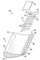
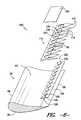
- FIG. 3is an exploded perspective view of a portion of a rotor blade, fastening device, and rotor blade component according to one embodiment of the present disclosure
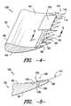
- FIG. 4is a perspective view of a portion of a rotor blade, fastening device, and rotor blade component according to one embodiment of the present disclosure
- FIG. 5is a cross-sectional view of a rotor blade, fastening device, and rotor blade component along the line 5 - 5 of FIG. 4 according to one embodiment of the present disclosure
- FIG. 6is an exploded perspective view of a portion of a rotor blade, fastening device, and rotor blade component according to another embodiment of the present disclosure
- FIG. 7is a perspective view of a portion of a rotor blade, fastening device, and rotor blade component according to another embodiment of the present disclosure
- FIG. 8is a cross-sectional view of a rotor blade, fastening device, and rotor blade component along the line 8 - 8 of FIG. 7 according to another embodiment of the present disclosure
- FIG. 9is a perspective view of a portion of a rotor blade, fastening device, and rotor blade component according to yet another embodiment of the present disclosure.
- FIG. 10is an exploded cross-sectional view of a rotor blade, fastening device, and rotor blade component along the line 10 - 10 of FIG. 9 according to yet another embodiment of the present disclosure.
- FIG. 1is a perspective view of an exemplary wind turbine 10 .
- wind turbine 10is a horizontal-axis wind turbine.
- wind turbine 10may be a vertical-axis wind turbine.
- wind turbine 10includes a tower 12 that extends from a support surface 14 , a nacelle 16 mounted on tower 12 , and a rotor 18 that is coupled to nacelle 16 .
- Rotor 18includes a rotatable hub 20 and at least one rotor blade 22 coupled to and extending outward from hub 20 .
- rotor 18has three rotor blades 22 .
- rotor 18includes more or less than three rotor blades 22 .
- tower 12is fabricated from tubular steel to define a cavity (not shown in FIG. 1 ) between support surface 14 and nacelle 16 .
- tower 12is any suitable type of tower having any suitable height.
- Rotor blades 22are spaced about hub 20 to facilitate rotating rotor 18 to enable kinetic energy to be transferred from the wind into usable mechanical energy, and subsequently, electrical energy.
- Rotor blades 22are mated to hub 20 by coupling a blade root portion 24 to hub 20 at a plurality of load transfer regions 26 .
- Load transfer regions 26have a hub load transfer region and a blade load transfer region (both not shown in FIG. 1 ). Loads induced to rotor blades 22 are transferred to hub 20 via load transfer regions 26 .
- rotor blades 22have a length ranging from about 15 meters (m) to about 91 m.
- rotor blades 22may have any suitable length that enables wind turbine 10 to function as described herein.
- blade lengthsinclude 10 m or less, 20 m, 37 m, or a length that is greater than 91 m.
- rotor 18is rotated about an axis of rotation 30 .
- rotor blades 22are also subjected to various forces and moments. As such, rotor blades 22 may deflect and/or rotate from a neutral, or non-deflected, position to a deflected position.
- a pitch angle or blade pitch of rotor blades 22may be changed by a pitch adjustment system 32 to control the load and power generated by wind turbine 10 by adjusting an angular position of at least one rotor blade 22 relative to wind vectors.
- Pitch axes 34 for rotor blades 22are shown.
- pitch adjustment system 32may change a blade pitch of rotor blades 22 such that rotor blades 22 are moved to a feathered position, such that the perspective of at least one rotor blade 22 relative to wind vectors provides a minimal surface area of rotor blade 22 to be oriented towards the wind vectors, which facilitates reducing a rotational speed of rotor 18 and/or facilitates a stall of rotor 18 .
- a blade pitch of each rotor blade 22is controlled individually by a control system 36 .
- the blade pitch for all rotor blades 22may be controlled simultaneously by control system 36 .
- a yaw direction of nacelle 16may be controlled about a yaw axis 38 to position rotor blades 22 with respect to direction 28 .
- control system 36is shown as being centralized within nacelle 16 , however, control system 36 may be a distributed system throughout wind turbine 10 , on support surface 14 , within a wind farm, and/or at a remote control center.
- Control system 36includes a processor 40 configured to perform the methods and/or steps described herein. Further, many of the other components described herein include a processor.
- processoris not limited to integrated circuits referred to in the art as a computer, but broadly refers to a controller, a microcontroller, a microcomputer, a programmable logic controller (PLC), an application specific integrated circuit, and other programmable circuits, and these terms are used interchangeably herein. It should be understood that a processor and/or a control system can also include memory, input channels, and/or output channels.
- the rotor blade 22may include a plurality of individual blade segments 52 aligned in an end-to-end order from a blade tip 54 to a blade root 56 .
- Each of the individual blade segments 52is uniquely configured so that the plurality of blade segments 52 define a complete rotor blade 22 having a designed aerodynamic profile, length, and other desired characteristics.
- each of the blade segments 52may have an aerodynamic profile that corresponds to the aerodynamic profile of adjacent blade segments 52 .
- the aerodynamic profiles of the blade segments 52form a continuous aerodynamic profile of the rotor blade 22 .
- the rotor blade 22may be formed as a singular, unitary blade having the designed aerodynamic profile, length, and other desired characteristics.
- the complete rotor blade 22may have a swept shape giving it a curved contoured aerodynamic profile running from the distal end to the proximal end of the rotor blade 22 .
- the rotor blade 22may have a non-swept shape and respective aerodynamic profile.
- the rotor blade 22may include a pressure side 62 and a suction side 64 extending between a leading edge 66 and a trailing edge 68 .
- the rotor blade assembly 100may include, for example, a rotor blade 22 and a rotor blade component 110 fastened to the rotor blade 22 .
- the rotor blade component 110may be configured to perform any variety of functions.
- the rotor blade component 110may be a noise reducer 110 .
- the noise reducer 110may reduce the aerodynamic noise being emitted from the rotor blade 22 during operation of the wind turbine 10 .
- the rotor blade component 110may be, for example, a lightning receptor, a fairing, a vortex generator panel, a boundary layer turbulator, or any other component that may be fastened to the rotor blade 22 of a wind turbine 10 .
- the rotor blade component 110may be fastened to the rotor blade 22 adjacent the trailing edge 68 of the rotor blade 22 .
- the rotor blade component 110may be fastened to the rotor blade 22 adjacent the leading edge 66 of the rotor blade 22 , or adjacent the tip 54 or the root 56 of the rotor blade 22 , or at any other suitable position on the rotor blade 22 .
- the rotor blade component 110may be disposed on the pressure side 62 of the rotor blade 22 , or on the suction side 64 of the rotor blade, as discussed below.
- the rotor blade component 110may be disposed on and fastened to the rotor blade 22 only on the pressure side 62 or the suction side 64 , so as to not interrupt the aerodynamic profile of the rotor blade 22 on the other side.
- the rotor blade component 110may be a noise reducer 110 .
- the noise reducer 110may include, for example, a plurality of projections 112 .
- the plurality of projections 112may be spaced apart from each other, defining a plurality of indentations 114 therebetween.
- the projections 112 and indentations 114may be generally V-shaped or U-shaped, or may have any other shape or configuration suitable for reducing the noise being emitted from the rotor blade 22 during operation of the wind turbine 10 .
- the projections 112 and indentations 114may form serrated edges, as is understood in the art.
- the noise reducer 110may further define a plurality of contouring notches 116 .
- each of the indentations 114 , or a portion of the indentations 114may include a contouring notch 116 .
- the contouring notches 116may be separate from the indentations 114 .
- the contouring notches 116may allow the noise reducer 110 to have an aerodynamic profile that corresponds to the aerodynamic profile of the rotor blade 22 .
- the contouring notches 116may reduce the surface area of the noise reducer 110 , thus reducing stresses in the noise reducer 110 and allowing the noise reducer to more easily bend while maintaining suitable stiffness and rigidity.
- the contouring notches 116may allow the noise reducer 110 to bend and match the contours of the aerodynamic profile of the rotor blade 22 .
- the contouring notches 116may have any suitable shape and size.
- the contouring notchesmay be generally circular or oval-shaped, or may be rectangular, triangular, diamond-shaped, or may have any suitable polygonal shape.
- contouring notches 116 of the present disclosureare not limited to applications on noise reducers 110 , but may be defined in any rotor blade component 110 to allow the rotor blade component 110 to better bend and contour to correspond to the aerodynamic profile of the rotor blade 22 .
- the rotor blade component 110may be mechanically fastened to the rotor blade 22 , such that, for example, an adhesive is not required for fastening.
- the rotor blade assembly 100 of the present disclosuremay further include, for example, a fastening device 120 .
- the fastening device 120may be configured to fasten the rotor blade component 110 to the rotor blade 22 .
- the fastening device 120may include at least one button 122 , or a plurality of buttons 122 , and at least one mating groove 124 , or a plurality of mating grooves 124 .
- the fastening device 120 of the present disclosureis not limited to applications on a rotor blade assembly 100 .
- the fastening devicecould be utilized to attach various components to any portion of the wind turbine 10 , such as to the tower 12 , the nacelle 16 , or the hub 20 .
- the buttons 122 and mating grooves 124may be configured to fasten the rotor blade component 110 to the rotor blade 22 .
- the buttons 122may each include a head 126 and a stem 128 .
- the perimeter of the head 126may be greater than the perimeter of the stem 128 .
- the perimeter of the head 126may be smaller than the perimeter of the stem 128 , or the perimeters of the head 126 and stem 128 may be approximately equal.
- the head 126 and stem 128may each have any suitable shape and size.
- the head 126 and stem 128may be generally circular or oval-shaped, or may be rectangular, triangular, diamond-shaped, or may have any suitable polygonal shape.
- buttons 122may be associated with one of the rotor blade 22 or the rotor blade component 110 , while the mating grooves 124 may be associated with the other of the rotor blade 22 or rotor blade component 110 .
- the buttons 122may be disposed on the rotor blade 22 , while the mating grooves 124 are defined in the rotor blade component 110 .
- the buttons 122may be disposed adjacent the trailing edge 68 of the rotor blade 22 .
- the buttons 122may be spaced from each other and aligned along the trailing edge 68 of the rotor blade 22 .
- buttons 122may be disposed adjacent the leading edge 66 of the rotor blade 22 , or adjacent the tip 54 or the root 56 of the rotor blade 22 , or at any other suitable position on the rotor blade 22 . It should be understood that the buttons 122 need not be aligned as shown in FIGS. 3 through 8 , but may be disposed along the trailing edge 68 in any suitable pattern and having any suitable spacing. Further, it should be understood that the mating grooves 124 defined in the rotor blade component 110 may have a pattern and spacing corresponding to the pattern and spacing of the buttons 122 .
- the buttons 122may be disposed on the pressure side 62 of the rotor blade 22 .
- the buttons 122may be disposed adjacent the trailing edge 68 and on the pressure side 62 of the rotor blade 22 .
- the buttons 122may be disposed on the suction side 64 of the rotor blade 22 .
- the buttons 122may be disposed adjacent the trailing edge 68 and on the suction side 64 of the rotor blade 22 .
- buttons 122may be disposed on the pressure side 62 or the suction side 64 adjacent to any location on the rotor blade 22 , including the leading edge 66 , the tip 54 , the root 56 , or any other suitable position on the rotor blade 22 .
- buttons 122need only be disposed on one of the pressure side 62 or the suction side 64 , the other side of the rotor blade 22 need not be modified.
- the suction side 64 of the rotor blade 22need not be modified.
- the pressure side 62need not be modified.
- the aerodynamic profile of the rotor blade 22 on this sideis not disrupted.
- buttons 122may be disposed on the rotor blade component 110 , while the mating grooves 124 are defined in the rotor blade 22 .
- the mating grooves 124may be defined adjacent the trailing edge 68 of the rotor blade 22 .
- the mating grooves 124may be spaced from each other and aligned along the trailing edge 68 of the rotor blade 22 .
- the mating grooves 124may be defined adjacent the leading edge 66 of the rotor blade 22 , or adjacent the tip 54 or the root 56 of the rotor blade 22 , or at any other suitable position on the rotor blade 22 . It should be understood that the mating grooves 124 need not be aligned as shown in FIGS. 9 through 10 , but may be defined along the trailing edge 68 in any suitable pattern and having any suitable spacing. Further, it should be understood that the buttons 122 disposed on the rotor blade component 110 may have a pattern and spacing corresponding to the pattern and spacing of the mating grooves 124 .
- the mating grooves 124may be defined in the pressure side 62 of the rotor blade 22 .
- the mating grooves 124may be defined adjacent the trailing edge 68 and in the pressure side 62 of the rotor blade 22 .
- the mating grooves 124may be defined in the suction side 64 of the rotor blade 22 .
- the mating grooves 124may be defined adjacent the trailing edge 68 and in the suction side 64 of the rotor blade 22 .
- mating grooves 124may be defined in the pressure side 62 or the suction side 64 adjacent to any location on the rotor blade 22 , including the leading edge 66 , the tip 54 , the root 56 , or any other suitable position on the rotor blade 22 .
- the mating grooves 124need only be defined in one of the pressure side 62 or the suction side 64 , the other side of the rotor blade 22 need not be modified.
- the suction side 64 of the rotor blade 22need not be modified.
- the pressure side 62need not be modified.
- the aerodynamic profile of the rotor blade 22 on this sideis not disrupted.
- the rotor blade 22may further define a cutaway mounting surface 130 , as shown in FIGS. 3 through 10 .
- the cutaway mounting surface 130may be defined in the pressure side 62 or suction side 64 and adjacent the trailing edge 68 , leading edge 66 , tip 54 , root 56 , or any other suitable position on the rotor blade 22 .
- the buttons 122may be disposed on the cutaway mounting surface 130 .
- the mating grooves 124may be defined in the cutaway mounting surface 130 .
- the cutaway mounting surface 130may generally provide a mounting surface for the fastening device 120 and rotor blade component 110 that has a relatively low profile, so as to minimize any aerodynamic distortion to the rotor blade 22 caused by the fastening device 120 and rotor blade component 110 .
- the mating grooves 124may be configured to accept corresponding buttons 122 therein, thereby fastening the rotor blade component 110 to the rotor blade 22 .
- the mating grooves 124may have perimeters that are approximately equal to the perimeters of the stems 128 .
- the mating grooves 124may include inlet portions 132 configured to secure the buttons 122 .
- the inlet portion 132 of a mating groove 124may be an opening in the mating groove 124 that allows the stem 128 of a button 122 to enter and engage the mating groove 124 .
- the inlet portion 132may be sufficiently narrow relative to the stem 128 such that the stem 128 , upon entering the mating groove 124 through the inlet portion 132 , is secured in the mating groove 124 .
- the portions of the projections 112 that define the boundary of an inlet portion 132may be resiliently deformable.
- these portions of the projections 112may deform to allow the stem 128 to enter the mating groove 124 , and may then return to their original position after the stem 128 has entered the mating groove 124 , securing the stem 128 in the mating groove 124 .
- the stems 128 of the buttons 122may be resiliently deformable, to allow the buttons 122 to squeeze through the inlet portions 132 into the mating grooves 124 .
- the mating grooves 124include the contouring notches 116 , i.e., the contouring notches 116 also serve as mating grooves 124 .
- the mating grooves 124 and contouring notches 116are separate features of the rotor blade component 110 and fastening device 120 .
- the mating grooves 124may include a first portion 134 and a second portion 136 .
- the first portion 134 of a mating groove 124may be configured to accommodate the corresponding button 122
- the second portion 136 of the mating groove 124may be configured to secure the corresponding button 122 .
- the first portion 134 of a mating groove 124may have a perimeter approximately equal to the perimeter of the head 126 of the corresponding button 122
- the second portion 136 of the mating groove 124may have a perimeter approximately equal to the perimeter of the stem 128 of the corresponding button 122 .
- buttons 122may be placed through the first portions 134 of the mating grooves 124 .
- the buttons 122may then be directed from the first portions 134 to the smaller second portions 136 , which may secure the stems 128 of the buttons 122 .
- the portions of the rotor blade component 110 or rotor blade 22 that define the boundary between the first portions 134 and the second portions 136may be resiliently deformable.
- these portionsmay deform to allow the stem 128 to enter the second portion 136 from the first portion 134 , and may then return to their original position after the stem 128 has entered the second portion 136 , securing the stem 128 in the mating groove 124 .
- the stems 128 of the buttons 122may be resiliently deformable, to allow the buttons 122 to squeeze through the boundary from the first portion 134 into the second portion 126 .
- buttons 122 of the present disclosuremay be attached to the rotor blade 22 or rotor blade component 110 using any suitable attachment device or method.
- the rotor blade 22 or rotor blade component 110may be fabricated or manufactured with the buttons 122 as an integral part, or the buttons 122 may be affixed using, for example, a suitable adhesive.
- the buttons 122may be attached to a mounting plate 140 using any suitable attachment device or method.
- the mating grooves 124may be defined in the mounting plate 140 .
- the mounting plate 140may then be attached to the rotor blade 22 or rotor blade component 110 , such as to the pressure side 62 or suction side 64 , or in some embodiments to the cutaway mounting surface 130 .
- the use of a mounting plate 140may, in some embodiments, allow the buttons 122 or mating grooves 124 to be retrofitted to the rotor blade 22 or rotor blade component 110 .
- the configuration of the buttons 122 and the mating grooves 124 of the fastening device 120 of the present disclosureallows the rotor blade components 110 to be quickly and easily attached to and removed from rotor blades 22 as desired.
- the rotor blade assembly 100may further include an adhesive layer 150 .
- the adhesive layer 150may be affixed to the rotor blade assembly 100 proximate the fastening device 120 .
- the adhesive layer 150may extend from the rotor blade 22 to the rotor blade component 110 , covering the buttons 122 and mating grooves 124 .
- the adhesive layer 150may further secure the rotor blade component 110 to the rotor blade 22 , and may improve the aerodynamic profile of the rotor blade 22 .
- the adhesive layer 150may provide a relatively smooth surface, covering the fastening device 120 . This relatively smooth surface may correspond to the aerodynamic profile of the rotor blade 22 , and may prevent or reduce turbulence that may result from disruptions in the rotor blade 22 caused by the fastening device 120 .
Landscapes
- Engineering & Computer Science (AREA)
- Life Sciences & Earth Sciences (AREA)
- Sustainable Development (AREA)
- Sustainable Energy (AREA)
- Chemical & Material Sciences (AREA)
- Combustion & Propulsion (AREA)
- Mechanical Engineering (AREA)
- General Engineering & Computer Science (AREA)
- Wind Motors (AREA)
- Turbine Rotor Nozzle Sealing (AREA)
Abstract
Description
Claims (20)
Priority Applications (4)
| Application Number | Priority Date | Filing Date | Title |
|---|---|---|---|
| US12/822,626US7909576B1 (en) | 2010-06-24 | 2010-06-24 | Fastening device for rotor blade component |
| DK201170289ADK178175B1 (en) | 2010-06-24 | 2011-06-09 | Fastening Device for Rotor Blade Component |
| CN201110184926.7ACN102297074B (en) | 2010-06-24 | 2011-06-23 | Fastening device for rotor blade component |
| DE102011051329.9ADE102011051329B4 (en) | 2010-06-24 | 2011-06-24 | Fastening device for a rotor blade component |
Applications Claiming Priority (1)
| Application Number | Priority Date | Filing Date | Title |
|---|---|---|---|
| US12/822,626US7909576B1 (en) | 2010-06-24 | 2010-06-24 | Fastening device for rotor blade component |
Publications (1)
| Publication Number | Publication Date |
|---|---|
| US7909576B1true US7909576B1 (en) | 2011-03-22 |
Family
ID=43741705
Family Applications (1)
| Application Number | Title | Priority Date | Filing Date |
|---|---|---|---|
| US12/822,626Expired - Fee RelatedUS7909576B1 (en) | 2010-06-24 | 2010-06-24 | Fastening device for rotor blade component |
Country Status (4)
| Country | Link |
|---|---|
| US (1) | US7909576B1 (en) |
| CN (1) | CN102297074B (en) |
| DE (1) | DE102011051329B4 (en) |
| DK (1) | DK178175B1 (en) |
Cited By (36)
| Publication number | Priority date | Publication date | Assignee | Title |
|---|---|---|---|---|
| US20090246025A1 (en)* | 2008-03-28 | 2009-10-01 | General Electric Company | Wind turbine protection |
| US20110006165A1 (en)* | 2009-07-10 | 2011-01-13 | Peter Ireland | Application of conformal sub boundary layer vortex generators to a foil or aero/ hydrodynamic surface |
| EP2514962A1 (en)* | 2011-04-19 | 2012-10-24 | Siemens Aktiengesellschaft | Spoiler for a wind turbine blade |
| WO2012156359A1 (en) | 2011-05-16 | 2012-11-22 | Lm Wind Power A/S | Wind turbine blade with noise reduction devices and related method |
| US20130164141A1 (en)* | 2011-12-22 | 2013-06-27 | General Electric Company | Blade with semi-rigid trailing edge |
| WO2014044412A1 (en)* | 2012-09-24 | 2014-03-27 | Siemens Aktiengesellschaft | A wind turbine blade with a noise reducing device |
| WO2014048437A1 (en)* | 2012-09-25 | 2014-04-03 | Vestas Wind Systems A/S | Noise attenuator for a wind turbine blade and a method for reducing wind turbine noise |
| US20140241880A1 (en)* | 2011-07-22 | 2014-08-28 | Lm Wp Patent Holding A/S | Method for retrofitting vortex generators on a wind turbine blade |
| US8840451B2 (en)* | 2012-01-24 | 2014-09-23 | Honeywell International Inc. | Cabin pressure outflow valve with simplified whistle eliminator |
| US20140328687A1 (en)* | 2013-05-03 | 2014-11-06 | General Electric Company | Wind turbine rotor blade assembly with surface features |
| US20150132135A1 (en)* | 2013-11-11 | 2015-05-14 | General Electric Company | Template for aligning surface features on a rotor blade |
| US20150139810A1 (en)* | 2013-11-20 | 2015-05-21 | General Electric Company | Noise reducing extension plate for rotor blade in wind turbine |
| US20150217846A1 (en)* | 2012-07-31 | 2015-08-06 | Russel Ian Hawkins | Propeller Including a Blade Back Flow Guide |
| US9341158B2 (en) | 2011-12-08 | 2016-05-17 | Inventus Holdings, Llc | Quiet wind turbine blade |
| US9523279B2 (en) | 2013-11-12 | 2016-12-20 | General Electric Company | Rotor blade fence for a wind turbine |
| US20170167510A1 (en)* | 2015-12-10 | 2017-06-15 | General Electric Company | Durable Riblets for Engine Environment |
| US20170218916A1 (en)* | 2014-08-05 | 2017-08-03 | Lm Wp Patent Holding A/S | Wind turbine blade provided with surface mounted device |
| US9897070B2 (en)* | 2011-12-08 | 2018-02-20 | Wobben Properties Gmbh | Rear casing, rotor blade with rear casing, and a wind turbine that comprises such a rotor blade |
| US9908600B2 (en)* | 2012-07-31 | 2018-03-06 | Russel Ian Hawkins | Propeller including a discrete blade edge cover member |
| US10082129B2 (en) | 2012-12-07 | 2018-09-25 | Wobben Properties Gmbh | Wind turbine |
| US20190113019A1 (en)* | 2016-04-15 | 2019-04-18 | Siemens Gamesa Renewable Energy A/S | Rotor blade with a serrated trailing edge |
| US10358931B2 (en) | 2016-02-19 | 2019-07-23 | Rolls-Royce Plc | Aerofoil |
| EP3540212A1 (en)* | 2018-03-16 | 2019-09-18 | Nordex Energy GmbH | Attachment for a wind energy assembly rotor blade |
| US10436175B2 (en) | 2014-04-02 | 2019-10-08 | Wobben Properties Gmbh | Method for attaching a toothed rear edge to a blade rear edge of a rotor blade |
| US10465652B2 (en) | 2017-01-26 | 2019-11-05 | General Electric Company | Vortex generators for wind turbine rotor blades having noise-reducing features |
| US10487798B2 (en) | 2016-08-05 | 2019-11-26 | General Electric Company | System and method for locating airflow modifiers for installation on a wind turbine rotor blade |
| US10487796B2 (en) | 2016-10-13 | 2019-11-26 | General Electric Company | Attachment methods for surface features of wind turbine rotor blades |
| EP3690231A1 (en)* | 2019-01-31 | 2020-08-05 | Nordex Energy GmbH | Attachment element for a wind energy assembly rotor blade, assembly and wind energy assembly rotor blade |
| US10746157B2 (en) | 2018-08-31 | 2020-08-18 | General Electric Company | Noise reducer for a wind turbine rotor blade having a cambered serration |
| US10767623B2 (en) | 2018-04-13 | 2020-09-08 | General Electric Company | Serrated noise reducer for a wind turbine rotor blade |
| US11143160B2 (en)* | 2014-07-14 | 2021-10-12 | Lm Wp Patent Holding A/S | Aeroshell extender piece for a wind turbine blade |
| US11236722B2 (en)* | 2018-06-27 | 2022-02-01 | Siemens Gamesa Renewable Energy A/S | Aerodynamic structure |
| US11359600B2 (en) | 2018-06-27 | 2022-06-14 | Siemens Gamesa Renewable Energy A/S | Aerodynamic structure |
| US20220195984A1 (en)* | 2019-02-26 | 2022-06-23 | Wind Buzz Ltd. | Yaw control device for a wind turbine |
| US11378487B2 (en) | 2017-07-14 | 2022-07-05 | Siemens Gamesa Renewable Energy A/S | Determining at least one characteristic of a boundary layer of a wind turbine rotor blade |
| US11802540B2 (en)* | 2018-01-17 | 2023-10-31 | Wobben Properties Gmbh | Wind turbine and rotor blade for a wind turbine |
Families Citing this family (7)
| Publication number | Priority date | Publication date | Assignee | Title |
|---|---|---|---|---|
| US7976276B2 (en)* | 2010-11-04 | 2011-07-12 | General Electric Company | Noise reducer for rotor blade in wind turbine |
| DE102013204637A1 (en)* | 2013-03-15 | 2014-09-18 | Wobben Properties Gmbh | Wind turbine |
| DE102016002350A1 (en)* | 2016-02-29 | 2017-08-31 | Senvion Gmbh | Serrations with relief slots |
| CN106695001B (en)* | 2017-02-16 | 2018-08-14 | 北京金风科创风电设备有限公司 | Slot forming device for a blade, blade assembly and processing method for a blade |
| CN109185042B (en)* | 2018-08-06 | 2019-08-09 | 北京源深节能技术有限责任公司 | The installation method of wind-driven generator leaf tail wing flap |
| EP3667068A1 (en)* | 2018-12-13 | 2020-06-17 | Siemens Gamesa Renewable Energy A/S | Adaptable spoiler for a wind turbine blade |
| US12215667B2 (en)* | 2019-05-10 | 2025-02-04 | Blade Dynamics Limited | Longitudinal edge extension |
Citations (5)
| Publication number | Priority date | Publication date | Assignee | Title |
|---|---|---|---|---|
| US4089618A (en)* | 1974-07-02 | 1978-05-16 | Rotron Incorporated | Fan with noise reduction |
| US5088665A (en)* | 1989-10-31 | 1992-02-18 | The United States Of America As Represented By The Administrator Of The National Aeronautics And Space Administration | Serrated trailing edges for improving lift and drag characteristics of lifting surfaces |
| US5533865A (en)* | 1993-11-04 | 1996-07-09 | Stork Product Engineering B.V. | Wind turbine |
| US6830436B2 (en)* | 2002-02-22 | 2004-12-14 | Mitsubishi Heavy Industries, Ltd. | Wind turbine provided with nacelle |
| US7059833B2 (en) | 2001-11-26 | 2006-06-13 | Bonus Energy A/S | Method for improvement of the efficiency of a wind turbine rotor |
Family Cites Families (25)
| Publication number | Priority date | Publication date | Assignee | Title |
|---|---|---|---|---|
| GB265089A (en)* | 1926-09-08 | 1927-02-03 | Stanley Hubert Fox | A new or improved fastening for collapsible and other boxes and structures |
| FR2543623B1 (en)* | 1983-04-01 | 1985-07-19 | Paris & Du Rhone | DEVICE FOR SUSPENDING A LOOP AT THE END OF A ROD |
| JPS6032123U (en)* | 1983-08-11 | 1985-03-05 | 河西工業株式会社 | Bracket for mounting automotive interior parts |
| DE3414845A1 (en)* | 1984-04-19 | 1985-06-20 | Daimler-Benz Ag, 7000 Stuttgart | Detachable attachment of a component to a supporting part which is in the form of a plate |
| US6010306A (en)* | 1997-05-05 | 2000-01-04 | King Of Fans, Inc. | Quick assembly blades for ceiling fans |
| DE19806690A1 (en)* | 1998-02-18 | 1999-09-02 | Daimler Chrysler Ag | Mounting system for a component to a carrier plate |
| JP2000120524A (en)* | 1998-10-16 | 2000-04-25 | Mitsubishi Heavy Ind Ltd | Windmill blade |
| CN2460459Y (en)* | 1999-12-28 | 2001-11-21 | 邱晓波 | Combined plastic turnover box |
| CN2439559Y (en)* | 2000-07-12 | 2001-07-18 | 陈明寿 | Jointing device |
| DE10330733A1 (en)* | 2003-07-07 | 2005-02-17 | Eew Maschinenbau Gmbh | Rotor blade for wind turbines |
| CA2593477C (en)* | 2004-12-29 | 2010-02-09 | Vestas Wind Systems A/S | Method of manufacturing a wind turbine blade shell member with a fastening member and a wind turbine blade with a fastening member |
| US7458777B2 (en)* | 2005-09-22 | 2008-12-02 | General Electric Company | Wind turbine rotor assembly and blade having acoustic flap |
| DK176352B1 (en)* | 2005-12-20 | 2007-09-10 | Lm Glasfiber As | Profile series for blade for wind turbines |
| GB0609799D0 (en)* | 2006-05-18 | 2006-06-28 | Euro Projects Ltd | A turbine blade support assembly |
| GB2440954B (en)* | 2006-08-18 | 2008-12-17 | Insensys Ltd | Structural monitoring |
| FR2910083A1 (en)* | 2006-12-19 | 2008-06-20 | Renault Sas | Protective bodyside molding fixing system for door of motor vehicle, has hole for blocking translation of bodyside molding, where bodyside molding has pin with groove in which hook is inserted through top according to vertical axis |
| US7918653B2 (en)* | 2007-02-07 | 2011-04-05 | General Electric Company | Rotor blade trailing edge assemby and method of use |
| US7413408B1 (en)* | 2007-02-22 | 2008-08-19 | Samuel B Tafoya | Vibration-reducing and noise-reducing spoiler for helicopter rotors, aircraft wings, propellers, and turbine blades |
| US7901189B2 (en)* | 2007-05-14 | 2011-03-08 | General Electric Company | Wind-turbine blade and method for reducing noise in wind turbine |
| CN201080941Y (en)* | 2007-09-11 | 2008-07-02 | 沈阳博林特电梯有限公司 | Elevator car wall panel fast connecting structure |
| KR101439586B1 (en)* | 2007-12-10 | 2014-09-11 | 유미코르 | Negative electrode material for li-ion batteries |
| DE102008003188A1 (en) | 2008-01-04 | 2009-07-09 | General Electric Company | Rotor blade for use in wind energy plant, has blade body with rear edge and front edge, and multiple flexible bristles that are arranged on outer surface of blade body close to rear edge in row along longitudinal direction of blade |
| GB2462308A (en)* | 2008-08-01 | 2010-02-03 | Vestas Wind Sys As | Extension portion for wind turbine blade |
| US9239039B2 (en)* | 2008-10-27 | 2016-01-19 | General Electric Company | Active circulation control of aerodynamic structures |
| US7854594B2 (en)* | 2009-04-28 | 2010-12-21 | General Electric Company | Segmented wind turbine blade |
- 2010
- 2010-06-24USUS12/822,626patent/US7909576B1/ennot_activeExpired - Fee Related
- 2011
- 2011-06-09DKDK201170289Apatent/DK178175B1/ennot_activeIP Right Cessation
- 2011-06-23CNCN201110184926.7Apatent/CN102297074B/ennot_activeExpired - Fee Related
- 2011-06-24DEDE102011051329.9Apatent/DE102011051329B4/enactiveActive
Patent Citations (5)
| Publication number | Priority date | Publication date | Assignee | Title |
|---|---|---|---|---|
| US4089618A (en)* | 1974-07-02 | 1978-05-16 | Rotron Incorporated | Fan with noise reduction |
| US5088665A (en)* | 1989-10-31 | 1992-02-18 | The United States Of America As Represented By The Administrator Of The National Aeronautics And Space Administration | Serrated trailing edges for improving lift and drag characteristics of lifting surfaces |
| US5533865A (en)* | 1993-11-04 | 1996-07-09 | Stork Product Engineering B.V. | Wind turbine |
| US7059833B2 (en) | 2001-11-26 | 2006-06-13 | Bonus Energy A/S | Method for improvement of the efficiency of a wind turbine rotor |
| US6830436B2 (en)* | 2002-02-22 | 2004-12-14 | Mitsubishi Heavy Industries, Ltd. | Wind turbine provided with nacelle |
Cited By (55)
| Publication number | Priority date | Publication date | Assignee | Title |
|---|---|---|---|---|
| US20090246025A1 (en)* | 2008-03-28 | 2009-10-01 | General Electric Company | Wind turbine protection |
| US20110006165A1 (en)* | 2009-07-10 | 2011-01-13 | Peter Ireland | Application of conformal sub boundary layer vortex generators to a foil or aero/ hydrodynamic surface |
| EP2514962A1 (en)* | 2011-04-19 | 2012-10-24 | Siemens Aktiengesellschaft | Spoiler for a wind turbine blade |
| CN102748204A (en)* | 2011-04-19 | 2012-10-24 | 西门子公司 | Spoiler for a wind turbine blade |
| US9945353B2 (en) | 2011-04-19 | 2018-04-17 | Siemens Aktiengesellschaft | Spoiler for a wind turbine blade |
| WO2012156359A1 (en) | 2011-05-16 | 2012-11-22 | Lm Wind Power A/S | Wind turbine blade with noise reduction devices and related method |
| CN103782027A (en)* | 2011-05-16 | 2014-05-07 | Lmwp专利控股有限公司 | Wind turbine blade with noise reduction devices and related method |
| US9581133B2 (en) | 2011-05-16 | 2017-02-28 | Lm Windpower A/S | Wind turbine blade with noise reduction devices and related method |
| CN103782027B (en)* | 2011-05-16 | 2017-03-22 | Lm Wp 专利控股有限公司 | Wind turbine blade with noise reduction devices and related method |
| US9777703B2 (en)* | 2011-07-22 | 2017-10-03 | Lm Wind Power A/S | Method for retrofitting vortex generators on a wind turbine blade |
| US20140241880A1 (en)* | 2011-07-22 | 2014-08-28 | Lm Wp Patent Holding A/S | Method for retrofitting vortex generators on a wind turbine blade |
| US10145357B2 (en) | 2011-07-22 | 2018-12-04 | Lm Wp Patent Holding A/S | Method for retrofitting vortex generators on a wind turbine blade |
| US9897070B2 (en)* | 2011-12-08 | 2018-02-20 | Wobben Properties Gmbh | Rear casing, rotor blade with rear casing, and a wind turbine that comprises such a rotor blade |
| US9341158B2 (en) | 2011-12-08 | 2016-05-17 | Inventus Holdings, Llc | Quiet wind turbine blade |
| US20130164141A1 (en)* | 2011-12-22 | 2013-06-27 | General Electric Company | Blade with semi-rigid trailing edge |
| US8840451B2 (en)* | 2012-01-24 | 2014-09-23 | Honeywell International Inc. | Cabin pressure outflow valve with simplified whistle eliminator |
| US9908600B2 (en)* | 2012-07-31 | 2018-03-06 | Russel Ian Hawkins | Propeller including a discrete blade edge cover member |
| US20150217846A1 (en)* | 2012-07-31 | 2015-08-06 | Russel Ian Hawkins | Propeller Including a Blade Back Flow Guide |
| WO2014044412A1 (en)* | 2012-09-24 | 2014-03-27 | Siemens Aktiengesellschaft | A wind turbine blade with a noise reducing device |
| US10012207B2 (en) | 2012-09-24 | 2018-07-03 | Siemens Aktiengesellschaft | Wind turbine blade noise reduction teeth with stiffening rib |
| WO2014048437A1 (en)* | 2012-09-25 | 2014-04-03 | Vestas Wind Systems A/S | Noise attenuator for a wind turbine blade and a method for reducing wind turbine noise |
| US10082129B2 (en) | 2012-12-07 | 2018-09-25 | Wobben Properties Gmbh | Wind turbine |
| US9562513B2 (en)* | 2013-05-03 | 2017-02-07 | General Electric Company | Wind turbine rotor blade assembly with surface features |
| US10584676B2 (en)* | 2013-05-03 | 2020-03-10 | General Electric Company | Wind turbine rotor blade assembly with surface features |
| US20140328687A1 (en)* | 2013-05-03 | 2014-11-06 | General Electric Company | Wind turbine rotor blade assembly with surface features |
| US20150132135A1 (en)* | 2013-11-11 | 2015-05-14 | General Electric Company | Template for aligning surface features on a rotor blade |
| US9624782B2 (en)* | 2013-11-11 | 2017-04-18 | General Electric Company | Template for aligning surface features on a rotor blade |
| US9523279B2 (en) | 2013-11-12 | 2016-12-20 | General Electric Company | Rotor blade fence for a wind turbine |
| US20150139810A1 (en)* | 2013-11-20 | 2015-05-21 | General Electric Company | Noise reducing extension plate for rotor blade in wind turbine |
| US9494134B2 (en)* | 2013-11-20 | 2016-11-15 | General Electric Company | Noise reducing extension plate for rotor blade in wind turbine |
| US10436175B2 (en) | 2014-04-02 | 2019-10-08 | Wobben Properties Gmbh | Method for attaching a toothed rear edge to a blade rear edge of a rotor blade |
| US11143160B2 (en)* | 2014-07-14 | 2021-10-12 | Lm Wp Patent Holding A/S | Aeroshell extender piece for a wind turbine blade |
| US11274651B2 (en)* | 2014-08-05 | 2022-03-15 | Lm Wp Patent Holding A/S | Wind turbine blade provided with surface mounted device |
| US11746743B2 (en) | 2014-08-05 | 2023-09-05 | Lm Wp Patent Holding A/S | Wind turbine blade provided with surface mounted device |
| US11719221B2 (en) | 2014-08-05 | 2023-08-08 | Lm Wind Power A/S | Wind turbine blade provided with surface mounted device |
| US20170218916A1 (en)* | 2014-08-05 | 2017-08-03 | Lm Wp Patent Holding A/S | Wind turbine blade provided with surface mounted device |
| US10107302B2 (en)* | 2015-12-10 | 2018-10-23 | General Electric Company | Durable riblets for engine environment |
| US20170167510A1 (en)* | 2015-12-10 | 2017-06-15 | General Electric Company | Durable Riblets for Engine Environment |
| US10358931B2 (en) | 2016-02-19 | 2019-07-23 | Rolls-Royce Plc | Aerofoil |
| EP3208420B1 (en)* | 2016-02-19 | 2020-09-09 | Rolls-Royce plc | Aerofoil |
| US20190113019A1 (en)* | 2016-04-15 | 2019-04-18 | Siemens Gamesa Renewable Energy A/S | Rotor blade with a serrated trailing edge |
| US11002246B2 (en)* | 2016-04-15 | 2021-05-11 | Siemens Gamesa Renewable Energy A/S | Rotor blade with a serrated trailing edge |
| US10487798B2 (en) | 2016-08-05 | 2019-11-26 | General Electric Company | System and method for locating airflow modifiers for installation on a wind turbine rotor blade |
| US11274650B2 (en) | 2016-10-13 | 2022-03-15 | General Electric Company | Attachment methods for surface features of wind turbine rotor blades |
| US10487796B2 (en) | 2016-10-13 | 2019-11-26 | General Electric Company | Attachment methods for surface features of wind turbine rotor blades |
| US10465652B2 (en) | 2017-01-26 | 2019-11-05 | General Electric Company | Vortex generators for wind turbine rotor blades having noise-reducing features |
| US11378487B2 (en) | 2017-07-14 | 2022-07-05 | Siemens Gamesa Renewable Energy A/S | Determining at least one characteristic of a boundary layer of a wind turbine rotor blade |
| US11802540B2 (en)* | 2018-01-17 | 2023-10-31 | Wobben Properties Gmbh | Wind turbine and rotor blade for a wind turbine |
| EP3540212A1 (en)* | 2018-03-16 | 2019-09-18 | Nordex Energy GmbH | Attachment for a wind energy assembly rotor blade |
| US10767623B2 (en) | 2018-04-13 | 2020-09-08 | General Electric Company | Serrated noise reducer for a wind turbine rotor blade |
| US11236722B2 (en)* | 2018-06-27 | 2022-02-01 | Siemens Gamesa Renewable Energy A/S | Aerodynamic structure |
| US11359600B2 (en) | 2018-06-27 | 2022-06-14 | Siemens Gamesa Renewable Energy A/S | Aerodynamic structure |
| US10746157B2 (en) | 2018-08-31 | 2020-08-18 | General Electric Company | Noise reducer for a wind turbine rotor blade having a cambered serration |
| EP3690231A1 (en)* | 2019-01-31 | 2020-08-05 | Nordex Energy GmbH | Attachment element for a wind energy assembly rotor blade, assembly and wind energy assembly rotor blade |
| US20220195984A1 (en)* | 2019-02-26 | 2022-06-23 | Wind Buzz Ltd. | Yaw control device for a wind turbine |
Also Published As
| Publication number | Publication date |
|---|---|
| CN102297074A (en) | 2011-12-28 |
| DK178175B1 (en) | 2015-07-20 |
| DE102011051329B4 (en) | 2019-01-10 |
| DK201170289A (en) | 2011-12-25 |
| DE102011051329A1 (en) | 2011-12-29 |
| CN102297074B (en) | 2015-05-06 |
Similar Documents
| Publication | Publication Date | Title |
|---|---|---|
| US7909576B1 (en) | Fastening device for rotor blade component | |
| CN102374115B (en) | Blade extension for rotor blade in wind turbine | |
| US7976276B2 (en) | Noise reducer for rotor blade in wind turbine | |
| US7976283B2 (en) | Noise reducer for rotor blade in wind turbine | |
| US9239040B2 (en) | Root end assembly configuration for a wind turbine rotor blade and associated forming methods | |
| DK178192B1 (en) | Noise reduction device for rotor blades in a wind turbine | |
| US9074581B2 (en) | Cone angle insert for wind turbine rotor | |
| US20120027588A1 (en) | Root flap for rotor blade in wind turbine | |
| US10047719B2 (en) | Winglet for a wind turbine rotor blade | |
| EP2679805B1 (en) | Cone angle insert for wind turbine rotor | |
| US9551324B2 (en) | Pitch bearing assembly with stiffener | |
| AU2013231165B2 (en) | Noise reduction tab and method for wind turbine rotor blade | |
| US8858174B2 (en) | Wind turbine torque-speed control | |
| US20140112777A1 (en) | System and method for mitigating wake losses in a windfarm | |
| DK201270491A (en) | Wind turbine rotor blade joint | |
| US8956115B2 (en) | Blade extension and rotor blade assembly for wind turbine | |
| US10767623B2 (en) | Serrated noise reducer for a wind turbine rotor blade | |
| US9261074B2 (en) | Variable bolt parameters for a wind turbine rotor blade | |
| CN109236561B (en) | Intelligent layout design method and device for bolts of low-wind-speed wind turbine and wind turbine |
Legal Events
| Date | Code | Title | Description |
|---|---|---|---|
| AS | Assignment | Owner name:GE WIND ENERGY GMBH, GERMANY Free format text:ASSIGNMENT OF ASSIGNORS INTEREST;ASSIGNORS:VAN DER BOS, ROELANT;STARKE, ANDREAS G.W.;REEL/FRAME:024589/0595 Effective date:20100624 | |
| AS | Assignment | Owner name:GENERAL ELECTRIC COMPANY, NEW YORK Free format text:ASSIGNMENT OF ASSIGNORS INTEREST;ASSIGNOR:GE WIND ENERGY GMBH;REEL/FRAME:024623/0522 Effective date:20100630 | |
| STCF | Information on status: patent grant | Free format text:PATENTED CASE | |
| FPAY | Fee payment | Year of fee payment:4 | |
| MAFP | Maintenance fee payment | Free format text:PAYMENT OF MAINTENANCE FEE, 8TH YEAR, LARGE ENTITY (ORIGINAL EVENT CODE: M1552); ENTITY STATUS OF PATENT OWNER: LARGE ENTITY Year of fee payment:8 | |
| FEPP | Fee payment procedure | Free format text:MAINTENANCE FEE REMINDER MAILED (ORIGINAL EVENT CODE: REM.); ENTITY STATUS OF PATENT OWNER: LARGE ENTITY | |
| LAPS | Lapse for failure to pay maintenance fees | Free format text:PATENT EXPIRED FOR FAILURE TO PAY MAINTENANCE FEES (ORIGINAL EVENT CODE: EXP.); ENTITY STATUS OF PATENT OWNER: LARGE ENTITY | |
| STCH | Information on status: patent discontinuation | Free format text:PATENT EXPIRED DUE TO NONPAYMENT OF MAINTENANCE FEES UNDER 37 CFR 1.362 | |
| FP | Lapsed due to failure to pay maintenance fee | Effective date:20230322 |