US7909347B2 - Bicycle suspension system employing highly predictable pedalling characteristics - Google Patents
Bicycle suspension system employing highly predictable pedalling characteristicsDownload PDFInfo
- Publication number
- US7909347B2 US7909347B2US12/232,122US23212208AUS7909347B2US 7909347 B2US7909347 B2US 7909347B2US 23212208 AUS23212208 AUS 23212208AUS 7909347 B2US7909347 B2US 7909347B2
- Authority
- US
- United States
- Prior art keywords
- pivotal connection
- suspension system
- rear wheel
- bicycle
- linkage member
- Prior art date
- Legal status (The legal status is an assumption and is not a legal conclusion. Google has not performed a legal analysis and makes no representation as to the accuracy of the status listed.)
- Active, expires
Links
- 239000000725suspensionSubstances0.000titleclaimsabstractdescription46
- 230000001133accelerationEffects0.000claimsabstractdescription13
- 230000007423decreaseEffects0.000claimsabstract8
- 230000035939shockEffects0.000description11
- 239000006096absorbing agentSubstances0.000description9
- 230000006835compressionEffects0.000description8
- 238000007906compressionMethods0.000description8
- 230000005484gravityEffects0.000description7
- 230000000694effectsEffects0.000description2
- 238000005259measurementMethods0.000description2
- 238000010521absorption reactionMethods0.000description1
- 230000009286beneficial effectEffects0.000description1
- 230000002301combined effectEffects0.000description1
- 230000002452interceptive effectEffects0.000description1
- 238000004088simulationMethods0.000description1
- 230000003068static effectEffects0.000description1
Images


Classifications
- B—PERFORMING OPERATIONS; TRANSPORTING
- B62—LAND VEHICLES FOR TRAVELLING OTHERWISE THAN ON RAILS
- B62K—CYCLES; CYCLE FRAMES; CYCLE STEERING DEVICES; RIDER-OPERATED TERMINAL CONTROLS SPECIALLY ADAPTED FOR CYCLES; CYCLE AXLE SUSPENSIONS; CYCLE SIDE-CARS, FORECARS, OR THE LIKE
- B62K25/00—Axle suspensions
- B62K25/04—Axle suspensions for mounting axles resiliently on cycle frame or fork
- B62K25/12—Axle suspensions for mounting axles resiliently on cycle frame or fork with rocking arm pivoted on each fork leg
- B62K25/22—Axle suspensions for mounting axles resiliently on cycle frame or fork with rocking arm pivoted on each fork leg with more than one arm on each fork leg
- B62K25/26—Axle suspensions for mounting axles resiliently on cycle frame or fork with rocking arm pivoted on each fork leg with more than one arm on each fork leg for rear wheel
- B—PERFORMING OPERATIONS; TRANSPORTING
- B62—LAND VEHICLES FOR TRAVELLING OTHERWISE THAN ON RAILS
- B62K—CYCLES; CYCLE FRAMES; CYCLE STEERING DEVICES; RIDER-OPERATED TERMINAL CONTROLS SPECIALLY ADAPTED FOR CYCLES; CYCLE AXLE SUSPENSIONS; CYCLE SIDE-CARS, FORECARS, OR THE LIKE
- B62K25/00—Axle suspensions
- B62K25/04—Axle suspensions for mounting axles resiliently on cycle frame or fork
- B62K25/28—Axle suspensions for mounting axles resiliently on cycle frame or fork with pivoted chain-stay
- B62K25/286—Axle suspensions for mounting axles resiliently on cycle frame or fork with pivoted chain-stay the shock absorber being connected to the chain-stay via a linkage mechanism
Definitions
- the present inventionrelates to a bicycle rear suspension system which offers improved pedaling and bump absorption performance by means of combined controlled linear chain stay lengthening and anti-squat characteristics through the use of a linkage system.
- the first parameteris the rate of change of the distance from the bottom bracket pedal axis to the rear wheel axle, commonly known as dCSL. It is known that it is desirable to have a certain dCSL value at the point in the suspension's compression known as the sag point where the system is in static equilibrium under the rider's weight. However, it is undesirable to have high values for the dCSL at points farther in the suspension's compression as this creates a pull on the pedals when a larger bump is encountered as when riding over very rough terrain.
- the known systems that employ a reduction in dCSL as the system is further compressedgenerally display a curved relationship between dCSL and the vertical wheel travel resulting in unpredictable response to the rider when encountering bumps of various sizes.
- the present inventionemploys a reduction in dCSL with respect to increasing vertical wheel travel while displaying a linear relationship. This results in highly predictable response.
- the second parameteris the acceleration anti-squat effect created by the kinematics of the suspension system. This effect is tuned so that a weight transfer rearward as a result of forward acceleration does not result in varying amounts of suspension compression throughout the compression of the system. A value of 100% anti-squat results in no suspension compression as a result of weight transfer.
- the known systems that employ anti-squat to tune the compression of the suspensiongenerally display a curved relationship of percent anti-squat vs. vertical wheel travel.
- the present inventionemploys a reduction in percentage anti-squat with respect to increasing vertical wheel travel while displaying a linear relationship. Additionally, the point where 100% anti-squat is achieved is at the linear sag point. This results in an optimally tuned system that is very predictable throughout the range of suspension motion.
- the suspension systemis made up of a bicycle main frame and rear wheel triangle.
- the main frametypically but not in all cases consists of: a head tube for the steering apparatus, seat tube, down tube, top tube, and a bottom bracket for the pedal/drive apparatus, a connection to the front end of a spring/damper shock absorber, a connection to a first link, and a connection to a second link.
- the rear wheel triangleconsists of: a pair of seat stays, one end connecting to dropout and other to seat stay ends; a pair of chain stays, one end connecting to a dropout and the other to a chain stay yoke, a pair of dropouts to hold the rear wheel, a chain stay yoke that allows for the connection to the first link, and seat stay ends that allow for the connection to the second link and the shock absorber.
- the main frame and rear wheel triangle of the bicycleallow for the attachment of conventional bicycle components such as handlebars, a seat, the drivetrain and brakes in a standard configuration.
- the rear wheel trianglealso has attachment points to linkage members in specific locations that contribute to controlling the motion of the rear wheel axle.
- the first and the second linkcontribute to controlling the motion of the rear wheel axle and thus the rate of chainstay lengthening. Both links rotate clockwise when viewed from the drivetrain side of the bike.
- the second linkin some but not all configurations, also allows for the attachment of the shock absorber, and its configuration controls the ratio of the shock absorber compression relative to the rear wheel compression.
- the configuration of the linkage of the rear wheel suspension systemcontrols the motion of the intersection of the force lines running from pivot to pivot along the first and second linkage members. This intersection is commonly referred to as the instant center of the linkage. As the system is compressed, the instant center moves in a generally rearward and downward trajectory, but always in front of the most forward pivot of the first linkage member. This motion of the linkage instant center is responsible for the improved anti-squat characteristics.
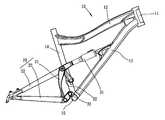
- FIG. 1is a profile view of the present invention to illustrate the components of the front triangle
- FIG. 2is a profile view of the present invention to illustrate the components of the rear triangle and linkage members
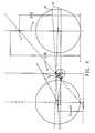
- FIG. 3is a side view shown the details for Anti-squat acceleration measurement
- FIG. 4is a side view shown Anti-squat acceleration measurement when bottom closer to the ground;
- FIG. 5is a side view shown Braking Anti Squat Percentage of the present invention.
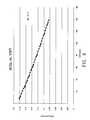
- FIG. 6is a graph of the derivative of chain stay length (dCSL) vs. vertical wheel travel (VWT) for the present invention
- FIG. 7is a graph of the acceleration anti-squat percentage vs. vertical wheel travel for the present invention.
- FIG. 8is a graph of the braking anti-squat percentage vs. vertical wheel travel for the present invention.
- FIG. 1 and FIG. 2depicts a preferred embodiment of a rear wheel suspension system of a bicycle of the present invention.
- the bicycle main frame 10generally includes a seat tube 14 and a down tube 13 both of which are attached to a bottom bracket 15 that houses a pedal assembly, a top tube 12 , together with the down tube 13 attached to the head tube 11 , and a front fork (not shown).
- main frame 10typically includes all of the foregoing members, alternative embodiments can have more or less than all of the foregoing members, and can include them in various forms, sizes, and configurations, and still achieve the intended functionality and beneficial aspects of the invention.
- the rear wheel suspension systemgenerally includes a first linkage member 33 , a rear wheel swingarm 20 , and a second linkage member 32 .
- the first linkage member 33 of the preferred embodimentis a link in which the distance between the pivotal connections between the first linkage member 33 and the main frame 10 and the first linkage member 33 and the rear triangle is approximately 58 mm.
- the pivotal connectionsare typically achieved through the use of bearings.
- the pivotal connection between the first linkage member 33 and the front triangleis located 30.5 mm behind the main frame pedal axis and 26 mm above the main frame pedal axis.
- pivotal connectionother than a bearing could be utilized for either pivotal connection
- the pivotal connection to the rear trianglecould be contained within either the first linkage member 33 or the rear triangle, and the distance between the pivotal connections of the first linkage member 33 as well as the main pivots location relative to the bottom bracket 15 could be adjusted to accommodate various configurations without changing the scope of the present invention.
- the rear wheel swingarm 20includes a pair of seat stays 22 and a pair of chain stays 23 that are joined to each other at their rearward ends proximate the axle of the rear wheel at a pair of rear wheel dropouts.
- An upright structure 21is engaged between the chain stays 23 and the seat stays 22 to provide a rigid triangular structure for the swingarm 20 .
- a chain stay yokeis joined to the forward end of the chain stays 23 , and houses a pivotal connection to the first linkage member 33 .
- Seat stay endsare joined to the forward end of the seat stays 22 and house a pivotal connection to the second linkage member 32 as well as a rearward connection to the shock absorber 31 .
- the rearward connection to the shock absorber 31is located approximately 65.4 mm from of the pivotal connection between the second linkage member 32 and the rear triangle.
- the distance between the chain stay pivot and the rear axle of the preferred embodimentis approximately 376 mm, and said length can be accomplished by various combinations of lengths of dropout, chain stay, and chain stay yoke.
- the distance between the seat stay pivotal connection between the rear triangle and the second linkage member and the rear wheel axle of the preferred embodimentis approximately 405 mm.
- the distance between the pivotal connections between the rear triangle and the first and second linkage members of the preferred embodimentis approximately 211 mm. It should be clear to one skilled in the art that a pivotal connection other than a bearing could be utilized for either pivotal connection, and that lengths of various members could be adjusted to accommodate various configurations without changing the scope of the present invention.
- the second linkage member 32has a pivotal connection to the rear triangle at one end, and a pivotal connection to the main frame 10 on the other end.
- the distance between the two pivotal connections of the preferred embodimentis approximately 98 mm.
- the pivotal connection between the second linkage member 32 and the main frame of the bicycleis located approximately 119.5 mm above the bottom bracket 15 and 17.7 mm behind the bottom bracket 15 .
- a shock absorber 31is pivotally engaged between the forward shock mount of the main frame 10 and the rearward shock mount of the rear triangle seat stay ends. As the rear wheel is articulated generally upwards along its axle path, the shock absorber 31 is compressed in length between the two mounting points providing resistance to the rear wheel's motion.
- line 51is drawn vertical through the front wheel
- line 52is drawn tangent to the rear chain gear and tangent to the front chainwheel
- line 53is drawn center of the rear wheel to the instant center (location that the CL of the links intersects)
- line 61is drawn from the contact patch of the rear wheel to the intersection point of the line 52 and line 53 , this line extends to hit line 51 , at the point it hits line 51 to the ground (vertical distance) is the point that is the anti squat point 71 .
- Center of gravity in the Y locationis shown in the FIG. 3 and FIG. 4 .
- the percent of Anti Squat accelerationis shown on the FIG. 3 and FIG. 4 but is the following equation: (Anti squat # ⁇ Center of Gravity #)/(Center of gravity #)+1.
- the percent Anti Squat brakingcan be calculated by: (Anti squat braking# ⁇ Center of Gravity)/(Center of gravity)+1.
- the frame center of gravityis determined from the individual parts center of gravity,
- the rider COGwas initially determined from “A Multibody Model for the Simulation of Bicycle Suspension Systems”. Waechter, Riess. and Zacharias in the Journal of Vehicle System Dynamics, 2002, Vol. 37, No. 1, pp 3-28.
Landscapes
- Engineering & Computer Science (AREA)
- Mechanical Engineering (AREA)
- Axle Suspensions And Sidecars For Cycles (AREA)
Abstract
Description
Claims (12)
Priority Applications (1)
| Application Number | Priority Date | Filing Date | Title |
|---|---|---|---|
| US12/232,122US7909347B2 (en) | 2008-09-11 | 2008-09-11 | Bicycle suspension system employing highly predictable pedalling characteristics |
Applications Claiming Priority (1)
| Application Number | Priority Date | Filing Date | Title |
|---|---|---|---|
| US12/232,122US7909347B2 (en) | 2008-09-11 | 2008-09-11 | Bicycle suspension system employing highly predictable pedalling characteristics |
Publications (2)
| Publication Number | Publication Date |
|---|---|
| US20100059965A1 US20100059965A1 (en) | 2010-03-11 |
| US7909347B2true US7909347B2 (en) | 2011-03-22 |
Family
ID=41798555
Family Applications (1)
| Application Number | Title | Priority Date | Filing Date |
|---|---|---|---|
| US12/232,122Active2029-01-30US7909347B2 (en) | 2008-09-11 | 2008-09-11 | Bicycle suspension system employing highly predictable pedalling characteristics |
Country Status (1)
| Country | Link |
|---|---|
| US (1) | US7909347B2 (en) |
Cited By (13)
| Publication number | Priority date | Publication date | Assignee | Title |
|---|---|---|---|---|
| US8459680B2 (en) | 2010-05-14 | 2013-06-11 | Specialized Bicycle Components, Inc. | Bicycle frame |
| US9156521B2 (en) | 2013-12-23 | 2015-10-13 | Wayne Lumpkin | Bicycle frame rear suspension with flexing frame segment |
| US20180057101A1 (en)* | 2016-08-24 | 2018-03-01 | Jochen Klieber | Suspended two-wheeled vehicle frame |
| US20180099723A1 (en)* | 2016-10-06 | 2018-04-12 | Cesar Rojo Vidal | Suspension system for bicycles or other similar vehicles |
| US10293881B2 (en) | 2004-09-15 | 2019-05-21 | Yeti Cycling, Llc | Rear suspension system for a bicycle |
| US10343742B2 (en) | 2010-08-20 | 2019-07-09 | Yeti Cycling, Llc | Link suspension system |
| US20200247500A1 (en)* | 2019-02-01 | 2020-08-06 | Yeti Cycling, Llc | Multi-body vehicle suspension linkage |
| US10766563B2 (en) | 2013-01-16 | 2020-09-08 | Yeti Cyclying, Llc | Rail suspension with integral shock and dampening mechanism |
| US10822048B2 (en) | 2010-08-20 | 2020-11-03 | Yeti Cycling, Llc | Reciprocating rail movement suspension system |
| US10926830B2 (en) | 2017-07-07 | 2021-02-23 | Yeti Cycling, Llc | Vehicle suspension linkage |
| US11173983B2 (en) | 2017-03-17 | 2021-11-16 | Yeti Cycling, Llc | Vehicle suspension linkage |
| US12145684B2 (en) | 2019-12-24 | 2024-11-19 | Yeti Cycling, Llc | Constrained multiple instantaneous velocity center linkage assembly for vehicle suspension |
| US12384484B2 (en) | 2020-11-18 | 2025-08-12 | Yeti Cycling, Llc | Integrated motor mount and suspension pivot |
Families Citing this family (18)
| Publication number | Priority date | Publication date | Assignee | Title |
|---|---|---|---|---|
| US8272657B2 (en) | 2005-11-14 | 2012-09-25 | Santa Cruz Bicycles, Inc. | Bicycle rear suspension system with controlled variable shock rate |
| US7837213B2 (en)* | 2007-04-16 | 2010-11-23 | Trek Bicycle Corporation | Bicycle rear wheel suspension system |
| US8439383B2 (en)* | 2009-06-30 | 2013-05-14 | Specialized Bicycle Components, Inc. | Bicycle shock with extension arms |
| US8403350B2 (en) | 2010-05-14 | 2013-03-26 | Specialized Bicycle Components, Inc. | Seatstay suspension mount |
| WO2012122634A1 (en) | 2011-03-14 | 2012-09-20 | Cmh Plus Holdings Ltd. | Bicycle suspension system |
| US9216791B2 (en)* | 2011-03-14 | 2015-12-22 | Christopher Hudec | Bicycle suspension system |
| US8998235B2 (en) | 2012-03-23 | 2015-04-07 | Level One Engineering Llc | Bicycle rear suspension system |
| WO2013192622A1 (en)* | 2012-06-23 | 2013-12-27 | Bicycle Fabrications Llc | Bicycle rear suspension with a two axis wheel path |
| DE102013012390B4 (en) | 2012-08-03 | 2024-06-27 | Specialized Bicycle Components, Inc. | Bicycle shock absorber with extension arms |
| DE202015002990U1 (en)* | 2015-04-23 | 2016-07-26 | Canyon Bicycles Gmbh | bicycle frame |
| US10618595B2 (en) | 2017-03-23 | 2020-04-14 | Darrell W Voss | Vehicle |
| US11548587B2 (en) | 2017-03-23 | 2023-01-10 | Darrell W Voss | Vehicle |
| US10723410B2 (en)* | 2017-03-23 | 2020-07-28 | Darrell W Voss | Vehicle |
| US10745078B2 (en) | 2017-04-19 | 2020-08-18 | Damon Madsen | Rear wheel suspension system for a two-wheeled vehicle |
| US10933941B2 (en) | 2017-04-19 | 2021-03-02 | Damon Madsen | Rear wheel suspension system for a two-wheeled vehicle |
| US11040754B2 (en) | 2019-01-18 | 2021-06-22 | Sram, Llc | Dampers for bicycle suspension components |
| US11440613B2 (en)* | 2019-05-29 | 2022-09-13 | Timothy Saul Lane | Bicycle suspension |
| KR102391181B1 (en)* | 2020-07-31 | 2022-04-27 | (주)엠비에스코퍼레이션 | Bicycle frame |
Citations (9)
| Publication number | Priority date | Publication date | Assignee | Title |
|---|---|---|---|---|
| US6688626B2 (en)* | 2000-03-20 | 2004-02-10 | Andreas Felsl | Bicycle |
| US7100930B2 (en)* | 2003-09-15 | 2006-09-05 | Neal Tate Saiki | Bicycle rear suspension system |
| US7240912B2 (en)* | 2004-07-27 | 2007-07-10 | Atb Sales Limited | Bicycle rear suspension |
| US20080023935A1 (en)* | 2006-07-21 | 2008-01-31 | Mcandrews Michael | Bicycle suspension damping system |
| US7350797B2 (en)* | 2002-09-06 | 2008-04-01 | Ryan Michael Carroll | Rear bicycle suspension |
| US20080258427A1 (en)* | 2003-12-12 | 2008-10-23 | Noel Buckley | Rear suspension system for bicycles |
| US20090250897A1 (en)* | 2008-04-04 | 2009-10-08 | Tanouye Ted K | Force channeling mountain bike rear suspension |
| US20090261557A1 (en)* | 2008-04-17 | 2009-10-22 | Sotto Llc | Bicycle Rear Suspension System |
| US20100007113A1 (en)* | 2008-07-11 | 2010-01-14 | David Earle | Rear suspension system for bicycles |
- 2008
- 2008-09-11USUS12/232,122patent/US7909347B2/enactiveActive
Patent Citations (10)
| Publication number | Priority date | Publication date | Assignee | Title |
|---|---|---|---|---|
| US6688626B2 (en)* | 2000-03-20 | 2004-02-10 | Andreas Felsl | Bicycle |
| US7350797B2 (en)* | 2002-09-06 | 2008-04-01 | Ryan Michael Carroll | Rear bicycle suspension |
| US7100930B2 (en)* | 2003-09-15 | 2006-09-05 | Neal Tate Saiki | Bicycle rear suspension system |
| US20080258427A1 (en)* | 2003-12-12 | 2008-10-23 | Noel Buckley | Rear suspension system for bicycles |
| US7240912B2 (en)* | 2004-07-27 | 2007-07-10 | Atb Sales Limited | Bicycle rear suspension |
| US20080023935A1 (en)* | 2006-07-21 | 2008-01-31 | Mcandrews Michael | Bicycle suspension damping system |
| US20090250897A1 (en)* | 2008-04-04 | 2009-10-08 | Tanouye Ted K | Force channeling mountain bike rear suspension |
| US7703788B2 (en)* | 2008-04-04 | 2010-04-27 | Tanouye Ted K | Force channeling mountain bike rear suspension |
| US20090261557A1 (en)* | 2008-04-17 | 2009-10-22 | Sotto Llc | Bicycle Rear Suspension System |
| US20100007113A1 (en)* | 2008-07-11 | 2010-01-14 | David Earle | Rear suspension system for bicycles |
Cited By (24)
| Publication number | Priority date | Publication date | Assignee | Title |
|---|---|---|---|---|
| US10293881B2 (en) | 2004-09-15 | 2019-05-21 | Yeti Cycling, Llc | Rear suspension system for a bicycle |
| US8622411B1 (en) | 2010-05-14 | 2014-01-07 | Specialized Bicycle Components, Inc. | Bicycle frame |
| US8801023B2 (en) | 2010-05-14 | 2014-08-12 | Specialized Bicycle Components, Inc. | Bicycle frame |
| US9334011B2 (en) | 2010-05-14 | 2016-05-10 | Specialized Bicycle Components, Inc. | Bicycle frame |
| US8459680B2 (en) | 2010-05-14 | 2013-06-11 | Specialized Bicycle Components, Inc. | Bicycle frame |
| US10343742B2 (en) | 2010-08-20 | 2019-07-09 | Yeti Cycling, Llc | Link suspension system |
| US10822048B2 (en) | 2010-08-20 | 2020-11-03 | Yeti Cycling, Llc | Reciprocating rail movement suspension system |
| US12077243B2 (en) | 2010-08-20 | 2024-09-03 | Yeti Cycling, Llc | Reciprocating rail movement suspension system |
| US11485447B2 (en) | 2010-08-20 | 2022-11-01 | Yeti Cycling, Llc | Reciprocating rail movement suspension system |
| US10766563B2 (en) | 2013-01-16 | 2020-09-08 | Yeti Cyclying, Llc | Rail suspension with integral shock and dampening mechanism |
| US9156521B2 (en) | 2013-12-23 | 2015-10-13 | Wayne Lumpkin | Bicycle frame rear suspension with flexing frame segment |
| US9701361B2 (en) | 2013-12-23 | 2017-07-11 | Wayne Lumpkin | Bicycle frame rear suspension with flexing frame segment |
| US9359039B2 (en) | 2013-12-23 | 2016-06-07 | Wayne Lumpkin | Bicycle frame rear suspension with flexing frame segment |
| US10752316B2 (en)* | 2016-08-24 | 2020-08-25 | Jochen Klieber | Suspended two-wheeled vehicle frame |
| US20180057101A1 (en)* | 2016-08-24 | 2018-03-01 | Jochen Klieber | Suspended two-wheeled vehicle frame |
| US20180099723A1 (en)* | 2016-10-06 | 2018-04-12 | Cesar Rojo Vidal | Suspension system for bicycles or other similar vehicles |
| US11173983B2 (en) | 2017-03-17 | 2021-11-16 | Yeti Cycling, Llc | Vehicle suspension linkage |
| US10926830B2 (en) | 2017-07-07 | 2021-02-23 | Yeti Cycling, Llc | Vehicle suspension linkage |
| USD1023842S1 (en) | 2017-07-07 | 2024-04-23 | Yeti Cycling, Llc | Shock extension |
| US12344347B2 (en) | 2017-07-07 | 2025-07-01 | Yeti Cycling, Llc | Vehicle suspension linkage |
| US20200247500A1 (en)* | 2019-02-01 | 2020-08-06 | Yeti Cycling, Llc | Multi-body vehicle suspension linkage |
| US12077241B2 (en)* | 2019-02-01 | 2024-09-03 | Yeti Cycling, Llc | Multi-body vehicle suspension linkage |
| US12145684B2 (en) | 2019-12-24 | 2024-11-19 | Yeti Cycling, Llc | Constrained multiple instantaneous velocity center linkage assembly for vehicle suspension |
| US12384484B2 (en) | 2020-11-18 | 2025-08-12 | Yeti Cycling, Llc | Integrated motor mount and suspension pivot |
Also Published As
| Publication number | Publication date |
|---|---|
| US20100059965A1 (en) | 2010-03-11 |
Similar Documents
| Publication | Publication Date | Title |
|---|---|---|
| US7909347B2 (en) | Bicycle suspension system employing highly predictable pedalling characteristics | |
| US8434776B2 (en) | Bicycle frame with rear suspension system | |
| US8382136B2 (en) | Bicycle rear suspension system linkage | |
| EP2828144B1 (en) | Bicycle rear suspension system | |
| US8066297B2 (en) | Bicycle rear suspension linkage | |
| CA2538467C (en) | Bicycle with rear suspension | |
| US6843494B2 (en) | Rear suspension system for two-wheeled vehicles, particularly bicycles | |
| US7581743B2 (en) | Bicycle rear wheel suspension system with controlled variable shock rate | |
| US8733774B2 (en) | Bicycle rear suspension system with controlled variable shock rate | |
| US20090261557A1 (en) | Bicycle Rear Suspension System | |
| US8919799B2 (en) | Rear wheel suspension for a vehicle, in particular a bicycle | |
| US20040061305A1 (en) | Rear wheel suspension system for a bicycle | |
| US10377442B2 (en) | Suspension for a bicycle | |
| AU2016102059A4 (en) | Suspension for a bicycle | |
| US20230115232A1 (en) | Rear suspension system for bicycles |
Legal Events
| Date | Code | Title | Description |
|---|---|---|---|
| AS | Assignment | Owner name:A-PRO TECH CO., LTD.,TAIWAN Free format text:ASSIGNMENT OF ASSIGNORS INTEREST;ASSIGNOR:EARLE, DAVID;REEL/FRAME:021571/0171 Effective date:20080727 Owner name:A-PRO TECH CO., LTD., TAIWAN Free format text:ASSIGNMENT OF ASSIGNORS INTEREST;ASSIGNOR:EARLE, DAVID;REEL/FRAME:021571/0171 Effective date:20080727 | |
| FEPP | Fee payment procedure | Free format text:PAT HOLDER NO LONGER CLAIMS SMALL ENTITY STATUS, ENTITY STATUS SET TO UNDISCOUNTED (ORIGINAL EVENT CODE: STOL); ENTITY STATUS OF PATENT OWNER: LARGE ENTITY | |
| STCF | Information on status: patent grant | Free format text:PATENTED CASE | |
| SULP | Surcharge for late payment | ||
| FPAY | Fee payment | Year of fee payment:4 | |
| MAFP | Maintenance fee payment | Free format text:PAYMENT OF MAINTENANCE FEE, 8TH YEAR, LARGE ENTITY (ORIGINAL EVENT CODE: M1552) Year of fee payment:8 | |
| MAFP | Maintenance fee payment | Free format text:PAYMENT OF MAINTENANCE FEE, 12TH YEAR, LARGE ENTITY (ORIGINAL EVENT CODE: M1553); ENTITY STATUS OF PATENT OWNER: LARGE ENTITY Year of fee payment:12 |