US7908501B2 - Progressive power control of a multi-port memory device - Google Patents
Progressive power control of a multi-port memory deviceDownload PDFInfo
- Publication number
- US7908501B2 US7908501B2US11/690,642US69064207AUS7908501B2US 7908501 B2US7908501 B2US 7908501B2US 69064207 AUS69064207 AUS 69064207AUS 7908501 B2US7908501 B2US 7908501B2
- Authority
- US
- United States
- Prior art keywords
- port
- serial
- serial port
- power
- memory device
- Prior art date
- Legal status (The legal status is an assumption and is not a legal conclusion. Google has not performed a legal analysis and makes no representation as to the accuracy of the status listed.)
- Active, expires
Links
Images


Classifications
- G—PHYSICS
- G06—COMPUTING OR CALCULATING; COUNTING
- G06F—ELECTRIC DIGITAL DATA PROCESSING
- G06F1/00—Details not covered by groups G06F3/00 - G06F13/00 and G06F21/00
- G06F1/26—Power supply means, e.g. regulation thereof
- G06F1/32—Means for saving power
- G06F1/3203—Power management, i.e. event-based initiation of a power-saving mode
- G06F1/3234—Power saving characterised by the action undertaken
- G06F1/325—Power saving in peripheral device
- G06F1/3275—Power saving in memory, e.g. RAM, cache
- G—PHYSICS
- G06—COMPUTING OR CALCULATING; COUNTING
- G06F—ELECTRIC DIGITAL DATA PROCESSING
- G06F1/00—Details not covered by groups G06F3/00 - G06F13/00 and G06F21/00
- G06F1/26—Power supply means, e.g. regulation thereof
- G06F1/32—Means for saving power
- G—PHYSICS
- G06—COMPUTING OR CALCULATING; COUNTING
- G06F—ELECTRIC DIGITAL DATA PROCESSING
- G06F1/00—Details not covered by groups G06F3/00 - G06F13/00 and G06F21/00
- G06F1/26—Power supply means, e.g. regulation thereof
- G06F1/32—Means for saving power
- G06F1/3203—Power management, i.e. event-based initiation of a power-saving mode
- G06F1/3206—Monitoring of events, devices or parameters that trigger a change in power modality
- G06F1/3215—Monitoring of peripheral devices
- G06F1/3225—Monitoring of peripheral devices of memory devices
- G—PHYSICS
- G11—INFORMATION STORAGE
- G11C—STATIC STORES
- G11C5/00—Details of stores covered by group G11C11/00
- G11C5/14—Power supply arrangements, e.g. power down, chip selection or deselection, layout of wirings or power grids, or multiple supply levels
- G—PHYSICS
- G11—INFORMATION STORAGE
- G11C—STATIC STORES
- G11C7/00—Arrangements for writing information into, or reading information out from, a digital store
- G11C7/10—Input/output [I/O] data interface arrangements, e.g. I/O data control circuits, I/O data buffers
- G11C7/1075—Input/output [I/O] data interface arrangements, e.g. I/O data control circuits, I/O data buffers for multiport memories each having random access ports and serial ports, e.g. video RAM
- G—PHYSICS
- G11—INFORMATION STORAGE
- G11C—STATIC STORES
- G11C7/00—Arrangements for writing information into, or reading information out from, a digital store
- G11C7/22—Read-write [R-W] timing or clocking circuits; Read-write [R-W] control signal generators or management
- Y—GENERAL TAGGING OF NEW TECHNOLOGICAL DEVELOPMENTS; GENERAL TAGGING OF CROSS-SECTIONAL TECHNOLOGIES SPANNING OVER SEVERAL SECTIONS OF THE IPC; TECHNICAL SUBJECTS COVERED BY FORMER USPC CROSS-REFERENCE ART COLLECTIONS [XRACs] AND DIGESTS
- Y02—TECHNOLOGIES OR APPLICATIONS FOR MITIGATION OR ADAPTATION AGAINST CLIMATE CHANGE
- Y02D—CLIMATE CHANGE MITIGATION TECHNOLOGIES IN INFORMATION AND COMMUNICATION TECHNOLOGIES [ICT], I.E. INFORMATION AND COMMUNICATION TECHNOLOGIES AIMING AT THE REDUCTION OF THEIR OWN ENERGY USE
- Y02D10/00—Energy efficient computing, e.g. low power processors, power management or thermal management
- Y—GENERAL TAGGING OF NEW TECHNOLOGICAL DEVELOPMENTS; GENERAL TAGGING OF CROSS-SECTIONAL TECHNOLOGIES SPANNING OVER SEVERAL SECTIONS OF THE IPC; TECHNICAL SUBJECTS COVERED BY FORMER USPC CROSS-REFERENCE ART COLLECTIONS [XRACs] AND DIGESTS
- Y02—TECHNOLOGIES OR APPLICATIONS FOR MITIGATION OR ADAPTATION AGAINST CLIMATE CHANGE
- Y02D—CLIMATE CHANGE MITIGATION TECHNOLOGIES IN INFORMATION AND COMMUNICATION TECHNOLOGIES [ICT], I.E. INFORMATION AND COMMUNICATION TECHNOLOGIES AIMING AT THE REDUCTION OF THEIR OWN ENERGY USE
- Y02D30/00—Reducing energy consumption in communication networks
- Y02D30/50—Reducing energy consumption in communication networks in wire-line communication networks, e.g. low power modes or reduced link rate
Definitions
- the communications links across which computers—or parts of computers—talk to one anothermay be either serial or parallel.
- a parallel linktransmits several streams of data (perhaps representing particular bits of a stream of bytes) along multiple channels (wires, printed circuit tracks, optical fibers, etc.), while a serial link transmits a single stream of data over only two wires (a positive and complementary signal).
- a serial linkmust be inferior to a parallel one, because it can transmit less data on each clock tick.
- serial linkscan be clocked considerably faster than parallel links and can achieve a higher data rate.
- a number of factorsallow serial links to be clocked at a greater rate. First, clock skew between different channels is not an issue (for un-clocked serial links).
- serial connectionrequires fewer interconnecting cables (e.g. wires/fibers) and hence occupies less space allowing for better isolation of the channel from its surroundings.
- crosstalkis less of an issue because there are fewer conductors in proximity.
- serial linksare a better option because they are less expensive to implement.
- Many integrated circuits (ICs)have serial interfaces, as opposed to parallel ones, so that they have fewer pins and are therefore more economical.
- serial linkstend to use more power than parallel links.
- a serial linkchanges states very rapidly (called toggling). A small amount of power is consumed by each state change, thereby adding up to large power consumption over time.
- Serial linksare also typically terminated on each end by a termination resistor and bias resistors. Without termination resistors, reflections of fast driver edges can cause multiple data edges that can cause data corruption. Termination resistors also reduce electrical noise sensitivity due to the lower impedance.
- the bias resistorsbias the lines apart when the lines are not being driven. Without biasing resistors, the signal falls to zero (where electrical noise sensitivity is greatest) when no data is being transmitted. Both termination and bias resistors are therefore necessary; however, the additional resistance causes the link to consume a constant amount of power to keep the link alive.
- FIG. 1is a circuit diagram illustrating the components of a power control system in a serial port memory device.
- FIG. 2is a state machine that illustrates the states of a single port of the serial port memory device.
- FIG. 3is a state machine that illustrates the states of a host attached to a single port of the serial port memory device.
- FIG. 4is a state diagram illustrating the power-down modes available to each bank of the serial port memory device.
- FIG. 5is a circuit diagram that illustrates the termination of a serial link attached to a port.
- a method and system for progressively reducing the power consumption of a serial memory deviceis provided (the “power control system”).
- a multi-port serial memory deviceis described in U.S. patent application Ser. No. 10/045,297, entitled “COMMUNICATIONS ARCHITECTURE FOR MEMORY-BASED DEVICES,”, which is incorporated herein by reference.
- the power control systemconfigures the ports of a multi-port serial memory so that they can be enabled or disabled on a per-port basis. When data is not being transmitted or received on a port, a series of steps are taken to progressively de-power portions of the port and cause the port to enter into a low-power state. By disabling certain ports and placing ports in a low-power state, the power consumption of the overall serial port memory is significantly reduced.
- Each portmay be connected to a different host that accesses the device. Because ports can be shut down individually, hosts may still access the serial memory to perform certain functions using some ports while other ports are in a low-power state. In this way, the power control system reduces the power consumption of a device progressively, while still making the functionality of the device available for certain accessing hosts.
- the power control systemdetects that a port is not in use based on a shut-off criteria (e.g., the activity of the port). For example, if the port is not transmitting or receiving, then the power control system will shut the port down. The power control system may wait for the expiration of a timeout based on the last time that data was received by the port to determine that the port is not active. The power control system may also receive a command from the host that indicates that no new data will be transmitted for a period, and the power control system may shut down the port in response to the command.
- a shut-off criteriae.g., the activity of the port. For example, if the port is not transmitting or receiving, then the power control system will shut the port down. The power control system may wait for the expiration of a timeout based on the last time that data was received by the port to determine that the port is not active. The power control system may also receive a command from the host that indicates that no new data will be transmitted for a period, and the power control system
- the power control systemremoves the port clock signal and power for a shut down port.
- the port clockswitches rapidly and consumes power that is not needed when the port is not in use.
- the power control systemfurther reduces power consumption.
- the power and the clock signalcan be reapplied and the port returned to an operational state.
- the power control systemmay detect a change in the signal state on the line that indicates that the port is needed again by a host. Upon detecting the change in signal state, the power control system powers the port back up by reversing the steps taken to power the port down.
- the power control systemlowers the core power including the clock generator and PLL to further reduce power consumption.
- the core powersupplies each of the ports as well as common support circuitry. By removing the core power, the power control system achieves additional power savings. Since the clock generator and PLL can often consume a significant amount of power required by a circuit, shutting down the clock generator and PLL can result in significant power savings.
- the power control systemshuts down ports by removing termination at the port.
- the portis placed into common mode so that the voltage of the positive and complementary signals is the same. Removing the termination reduces power consumed. Moreover, neither the host nor the memory device is transmitting when a port is shut down, so both the host and memory device save power.
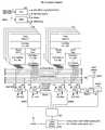
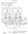
- FIG. 1is a circuit diagram illustrating the components of the power control system and the serial memory device in one embodiment.
- the serial memory devicecontains a phase-locked loop (PLL) 105 , multiple banks of memory 110 and 115 , four ports 120 , 125 , 130 , and 135 , a clock line 140 for each port, and a power line 155 for each port.
- the multiple banks of memory 110 and 115are coupled to the four serial ports 120 , 125 , 130 , and 135 , thereby making the banks of memory accessible by one or more host devices that are connected to the ports. While the memory device is depicted as having only eight banks in two groups of four and four ports in FIG. 1 , the memory device may have any number of banks and ports.
- the number of banks and portsare typically determined by the number of accessing hosts and the particular application for which the memory device is being used.
- the power control systemcomprises an activity detection line 145 , a clock switch 170 , and a power switch 175 for each port, as well as power control logic 160 , and a core power control module 165 .
- the activity detection line 145 for each portis coupled to the clock switch 170 , the power switch 175 , and the power control logic 160 .
- the power control logicperforms a logical AND operation on the activity detection line from each of the ports.
- the output from the power control logic 160is coupled to the power control module 165 . While FIG.
- the power control logicmay be implemented in software rather than in hardware, and the control signals used to trigger the power switch and the clock switch may be received from a central controller.
- the power control logicmay be more complex depending on the number of ports that are contained in the memory device.
- An activity detection line 145is coupled to each port of the memory device, and carries a signal indicating when the port is active and when the port is inactive.
- the signal on the activity detection lineis used to trigger various power-saving modes. For example, when the signal on the activity detection line indicates that a port is inactive, the power on power line 155 is disconnected from the port by switching off the power switch 175 . Removing power from the port reduces the power consumption of the memory device.
- the clock signal on clock line 140is disabled for the port by switching off the clock switch 170 . Shifting down the clock for the port reduces toggling and associated power consumption.
- the power control logic 160if power control logic 160 detects from the signal on the activity detection lines that all of the device ports are inactive, the power control logic signals the core power control module 165 . Upon receiving the signal that all ports are inactive, the core power control module may further reduce power consumption by shutting down the core clock (not shown) and power to the PLL 105 . Removing the clock signal and power to each port, or shutting down the core clock and power to the PLL, may be done immediately after a port is detected to be inactive, or after the expiration of a timeout period. The timeout period may vary in length for each port, for all ports, based on the application in which the memory device is being used, etc.
- FIG. 2is a state machine that illustrates the states of a single port of a serial port memory device.
- the portWhen the port is first activated, the port is in a system reset state 205 . The port then moves to a link reset state 210 . As long as no data signal is being received on the port, the port remains in this state. In the link reset state 210 , the port is not driven, and the voltage of the positive and complementary lines is the same due to termination. In order to minimize power, the clock and power to the port may also be removed as described above.
- the portmoves to a frame search state 215 . If the power and/or clock to the port are off when a signal is received, then the power and/or clock are turned back on.
- the portIn the frame search state 215 , the port is driven and the positive and complementary lines carry complementary signals.
- the portwaits for a SYNC message from the host and transmits a SYNC2 message to the host. If the port stops receiving a signal, the port returns to the link reset state 210 . If a SYNC message is detected from the host, then the port moves to an operational mode state 220 . In the operational mode state 220 , data is sent and received from the host. If the port stops receiving data, then the port can be powered down and returns to the link reset state 210 . If any errors are detected during transmission, the port returns to the frame search state 215 to resynchronize with the host.
- FIG. 3is a state machine that illustrates the states of a host attached to a single port of a serial port memory device.
- the hostWhen the host is first activated, the host is in a system reset state 305 . The host then moves to a link reset state 310 . As long as nothing is being sent, the host remains in this state. In the link reset state 310 , the link is not terminated, and the voltage of the positive and complementary lines is the same (i.e., the lines are in squelch mode).
- the hostwants to send additional data, the host moves to a frame search state 315 . In the frame search state 315 , the link is terminated and the positive and complementary lines carry complementary signals.
- the hostwaits for a SYNC2 message from the port and transmits a SYNC message to the port. If the host decides to disable the link (e.g., by a timeout expiring or error parity), then the host returns to the link reset state 310 . If a SYNC message is detected from the port, then the host moves to an operational mode state 320 , else if a SYNC2 message is received, then the host waits for a SYNC message from the port. In the operational mode state 320 , data is sent and received to the port. If at any point the host detects that the port is disabled, then the link can be powered down and the host returns to the link reset state 310 . If any errors are detected during transmission, the host also returns to the link reset state 310 to resynchronize with the port.
- the serial port memorymay implement additional power saving modes at the bank level. For example, it is not necessary to refresh banks with no data in them. Refreshing banks consumes power, so avoiding a refresh of a bank saves power.
- the serial port memoryhas four power-down modes, described as follows.
- FIG. 4is a state diagram illustrating the power-down modes available to each bank in some embodiments.
- the bankis initially in a power on state 405 .
- the bankthen moves to a set all MRS state 410 .
- each componentis sent a reset indication.
- the bankthen moves to a precharge all state 415 .
- the precharge all state 415the dynamic random access memory (DRAM) that composes the bank is precharged.
- the bankthen moves to an idle state 420 . If any link is active, then the bank moves to a self-refresh state 425 , described above. If all links are inactive, the bank moves to a precharge power down state 430 , also described above.
- DRAMdynamic random access memory
- a refresh message(REF) is received while in the idle state, then the bank moves from the idle state to an auto refresh state 435 and to a precharge state 470 .
- an activation message(ACT) is received while in the idle state, then the bank moves from the idle state 420 to an active state 440 . From the active state 440 , if all links are down, then the bank moves to an active power down state 445 , described above. From the active state 440 , reads and writes are processed. When a read is received, the bank moves to a read state 455 , and/or to a read auto precharge state 465 . When a write is received, the bank moves to a write state 450 and/or to a write auto precharge state 460 . When the read or write is complete, the bank moves to a precharge state 470 , and then back to the idle state 420 . The bank continues this cycle until power is removed.
- REFrefresh message
- ACTactivation message
- FIG. 5is a circuit diagram that illustrates the termination of the serial link.
- the host side of the linkcontains a termination detector 505 , a differential driver 510 , a beacon driver 515 , and a termination circuit 520 .
- the termination detector 505detects when termination is in effect on the memory side of the link.
- the differential driver 510drives a differential signal over the positive and complementary lines of the serial link.
- the beacon driver 515signals the memory side of the link that data is about to be transmitted so that the memory side of the link can engage the termination circuit 560 .
- the memory side of the serial linkcontains a differential sampler 550 , a beacon detector 555 , and a termination circuit 560 .
- the differential sampler 550detects a differential voltage signal on the serial link.
- the beacon detector 555detects the beacon signal sent by the beacon driver 515 .
- the termination circuit 560terminates the link when the link is active.
- the termination resistorcan be off when the link is inactive and on
- the power control systemcan be used in a variety of environments such as memory devices or other environments that use serial memory.
- the power control systemis particularly applicable to low-power applications such as cell phones, digital cameras, and other devices where battery life and power consumption are important concerns.
Landscapes
- Engineering & Computer Science (AREA)
- Theoretical Computer Science (AREA)
- Physics & Mathematics (AREA)
- General Engineering & Computer Science (AREA)
- General Physics & Mathematics (AREA)
- Multimedia (AREA)
- Power Engineering (AREA)
- Power Sources (AREA)
- Dram (AREA)
- Communication Control (AREA)
Abstract
Description
- Self-refresh—To enter the self-refresh mode, all ports are set by the power control system to idle state with no banks active. The
PLL 105 is stopped, and the external reference clock (not shown) may be stopped. All other clocks are gated off to save power. All peripheral circuitry is disabled to save power as well. All banks are precharged before entering this mode. The core provides its own refresh timing, so this mode can be sustained indefinitely. The reference clock should be stable before exiting this mode. Links are retrained after exiting this mode. - Precharge Power Down—To enter the precharge power down mode, all ports are set by the power control system to idle state with no banks active. The
PLL 105 is stopped, and the reference clock (not shown) may be stopped. All other clocks are gated off to save power. All peripheral circuitry is disabled to save power as well. All banks are precharged before entering this mode. No other operations are performed, so this mode should be exited before the next refresh cycle. The reference clock should be stable before exiting this mode. Links are retrained after exiting this mode. - Active Power Down—To enter the active power down mode, all ports are set by the power control system to idle state with some banks active. The
PLL 105 continues to run, and the reference clock remains stable. All peripheral circuitry is disabled to save power. No other operations are performed, so this mode should be exited before the next refresh cycle. Links are retrained after exiting this mode. - Idle—When a link enters idle state, that link ceases to use power. The link is retrained when the link is brought back up.
- Self-refresh—To enter the self-refresh mode, all ports are set by the power control system to idle state with no banks active. The
Claims (30)
Priority Applications (8)
| Application Number | Priority Date | Filing Date | Title |
|---|---|---|---|
| US11/690,642US7908501B2 (en) | 2007-03-23 | 2007-03-23 | Progressive power control of a multi-port memory device |
| TW097108671ATWI401696B (en) | 2007-03-23 | 2008-03-12 | Progressive power control of a multi-port memory device |
| CN2008800091094ACN101641745B (en) | 2007-03-23 | 2008-03-21 | Progressive Power Control for Multiport Memory Devices |
| JP2009554783AJP5238727B2 (en) | 2007-03-23 | 2008-03-21 | Incremental power control of multiport memory devices |
| CN201310175054.7ACN103257702B (en) | 2007-03-23 | 2008-03-21 | The progressive power of multiport storage device controls |
| EP08744214.1AEP2135249B1 (en) | 2007-03-23 | 2008-03-21 | Progressive power control of a multi-port memory device |
| PCT/US2008/057920WO2008118816A1 (en) | 2007-03-23 | 2008-03-21 | Progressive power control of a multi-port memory device |
| KR1020097022071AKR101448105B1 (en) | 2007-03-23 | 2008-03-21 | Progressive power control of multiport memory devices |
Applications Claiming Priority (1)
| Application Number | Priority Date | Filing Date | Title |
|---|---|---|---|
| US11/690,642US7908501B2 (en) | 2007-03-23 | 2007-03-23 | Progressive power control of a multi-port memory device |
Publications (2)
| Publication Number | Publication Date |
|---|---|
| US20080235528A1 US20080235528A1 (en) | 2008-09-25 |
| US7908501B2true US7908501B2 (en) | 2011-03-15 |
Family
ID=39775921
Family Applications (1)
| Application Number | Title | Priority Date | Filing Date |
|---|---|---|---|
| US11/690,642Active2029-07-25US7908501B2 (en) | 2007-03-23 | 2007-03-23 | Progressive power control of a multi-port memory device |
Country Status (7)
| Country | Link |
|---|---|
| US (1) | US7908501B2 (en) |
| EP (1) | EP2135249B1 (en) |
| JP (1) | JP5238727B2 (en) |
| KR (1) | KR101448105B1 (en) |
| CN (2) | CN101641745B (en) |
| TW (1) | TWI401696B (en) |
| WO (1) | WO2008118816A1 (en) |
Cited By (40)
| Publication number | Priority date | Publication date | Assignee | Title |
|---|---|---|---|---|
| US20100077240A1 (en)* | 2008-09-22 | 2010-03-25 | Sun Microsystems, Inc. | Methods and apparatuses for reducing power consumption of fully-buffered dual inline memory modules |
| US20110058440A1 (en)* | 2009-09-09 | 2011-03-10 | Fusion-Io, Inc. | Apparatus, system, and method for power reduction management in a storage device |
| US20110191608A1 (en)* | 2010-02-04 | 2011-08-04 | Cisco Technology, Inc. | System and method for managing power consumption in data propagation environments |
| US8443134B2 (en) | 2006-12-06 | 2013-05-14 | Fusion-Io, Inc. | Apparatus, system, and method for graceful cache device degradation |
| US20130132745A1 (en)* | 2011-11-22 | 2013-05-23 | Cisco Technology Inc. | System and method for network enabled wake for networks |
| US8489817B2 (en) | 2007-12-06 | 2013-07-16 | Fusion-Io, Inc. | Apparatus, system, and method for caching data |
| US8527693B2 (en) | 2010-12-13 | 2013-09-03 | Fusion IO, Inc. | Apparatus, system, and method for auto-commit memory |
| US8706968B2 (en) | 2007-12-06 | 2014-04-22 | Fusion-Io, Inc. | Apparatus, system, and method for redundant write caching |
| US8732501B1 (en) | 2009-02-09 | 2014-05-20 | Cisco Technology, Inc. | System and method for intelligent energy management in a network environment |
| US8745429B2 (en) | 2009-02-09 | 2014-06-03 | Cisco Technology, Inc. | System and method for querying for energy data in a network environment |
| US8793412B1 (en) | 2013-01-15 | 2014-07-29 | International Business Machines Corporation | Event-based execution buffer management |
| US8825937B2 (en) | 2011-02-25 | 2014-09-02 | Fusion-Io, Inc. | Writing cached data forward on read |
| US8849473B2 (en) | 2011-08-17 | 2014-09-30 | Cisco Technology, Inc. | System and method for notifying and for controlling power demand |
| US8966184B2 (en) | 2011-01-31 | 2015-02-24 | Intelligent Intellectual Property Holdings 2, LLC. | Apparatus, system, and method for managing eviction of data |
| US8972627B2 (en) | 2009-09-09 | 2015-03-03 | Fusion-Io, Inc. | Apparatus, system, and method for managing operations for data storage media |
| US8984216B2 (en) | 2010-09-09 | 2015-03-17 | Fusion-Io, Llc | Apparatus, system, and method for managing lifetime of a storage device |
| US9021158B2 (en) | 2009-09-09 | 2015-04-28 | SanDisk Technologies, Inc. | Program suspend/resume for memory |
| US9026812B2 (en) | 2010-06-29 | 2015-05-05 | Cisco Technology, Inc. | System and method for providing intelligent power management in a network environment |
| US9047178B2 (en) | 2010-12-13 | 2015-06-02 | SanDisk Technologies, Inc. | Auto-commit memory synchronization |
| US9058167B2 (en) | 2011-09-06 | 2015-06-16 | Cisco Technology, Inc. | Power conservation in a distributed digital video recorder/content delivery network system |
| US9104599B2 (en) | 2007-12-06 | 2015-08-11 | Intelligent Intellectual Property Holdings 2 Llc | Apparatus, system, and method for destaging cached data |
| CN104882155A (en)* | 2015-04-30 | 2015-09-02 | 厦门睿联创信息科技有限公司 | Low-power anti-loss safety U-disk |
| US9141169B2 (en) | 2012-01-20 | 2015-09-22 | Cisco Technology, Inc. | System and method to conserve power in an access network without loss of service quality |
| US9208071B2 (en) | 2010-12-13 | 2015-12-08 | SanDisk Technologies, Inc. | Apparatus, system, and method for accessing memory |
| US9218278B2 (en) | 2010-12-13 | 2015-12-22 | SanDisk Technologies, Inc. | Auto-commit memory |
| US9223514B2 (en) | 2009-09-09 | 2015-12-29 | SanDisk Technologies, Inc. | Erase suspend/resume for memory |
| US9251086B2 (en) | 2012-01-24 | 2016-02-02 | SanDisk Technologies, Inc. | Apparatus, system, and method for managing a cache |
| US9395777B2 (en) | 2012-09-27 | 2016-07-19 | Samsung Electronics Co., Ltd. | System-on-chip with capability for controlling power supply according to data transaction and method of operating the same |
| US9519540B2 (en) | 2007-12-06 | 2016-12-13 | Sandisk Technologies Llc | Apparatus, system, and method for destaging cached data |
| US9600184B2 (en) | 2007-12-06 | 2017-03-21 | Sandisk Technologies Llc | Apparatus, system, and method for coordinating storage requests in a multi-processor/multi-thread environment |
| US9666244B2 (en) | 2014-03-01 | 2017-05-30 | Fusion-Io, Inc. | Dividing a storage procedure |
| US9734086B2 (en) | 2006-12-06 | 2017-08-15 | Sandisk Technologies Llc | Apparatus, system, and method for a device shared between multiple independent hosts |
| US9767032B2 (en) | 2012-01-12 | 2017-09-19 | Sandisk Technologies Llc | Systems and methods for cache endurance |
| US9933950B2 (en) | 2015-01-16 | 2018-04-03 | Sandisk Technologies Llc | Storage operation interrupt |
| US9958924B2 (en) | 2013-08-28 | 2018-05-01 | Cisco Technology, Inc. | Configuration of energy savings |
| US10235516B2 (en) | 2016-05-10 | 2019-03-19 | Cisco Technology, Inc. | Method for authenticating a networked endpoint using a physical (power) challenge |
| US10281974B2 (en) | 2017-07-27 | 2019-05-07 | International Business Machines Corporation | Power management in multi-channel 3D stacked DRAM |
| US10564692B2 (en) | 2018-03-27 | 2020-02-18 | Windbond Electronics Corp. | Memory device and power reduction method of the same memory device |
| US10817421B2 (en) | 2010-12-13 | 2020-10-27 | Sandisk Technologies Llc | Persistent data structures |
| US10817502B2 (en) | 2010-12-13 | 2020-10-27 | Sandisk Technologies Llc | Persistent memory management |
Families Citing this family (34)
| Publication number | Priority date | Publication date | Assignee | Title |
|---|---|---|---|---|
| US8352764B2 (en)* | 2008-09-29 | 2013-01-08 | Intel Corporation | Dynamic squelch detection power control |
| US8127165B2 (en)* | 2009-02-05 | 2012-02-28 | Lsi Corporation | Multipath power management |
| US8230239B2 (en)* | 2009-04-02 | 2012-07-24 | Qualcomm Incorporated | Multiple power mode system and method for memory |
| KR20100130398A (en)* | 2009-06-03 | 2010-12-13 | 삼성전자주식회사 | How to Control Deep Power-Down Mode in Multi-Port Memory |
| US8856563B2 (en)* | 2009-10-02 | 2014-10-07 | International Business Machines Corporation | Remote power down control of a device |
| US9116701B2 (en) | 2010-06-11 | 2015-08-25 | Freescale Semiconductor, Inc. | Memory unit, information processing device, and method |
| US9141178B2 (en) | 2010-06-11 | 2015-09-22 | Freescale Semiconductor, Inc. | Device and method for selective reduced power mode in volatile memory units |
| US8412479B2 (en)* | 2010-06-29 | 2013-04-02 | Intel Corporation | Memory power estimation by means of calibrated weights and activity counters |
| KR101222082B1 (en)* | 2010-12-08 | 2013-01-14 | 삼성전자주식회사 | Method for reducing power consumptiom to multi-port memory device of memory link architecture |
| DE112012003293T5 (en)* | 2011-08-10 | 2014-05-08 | Gita Srivastava | Apparatus and method for improving data security in a host computer device and a peripheral device |
| US9052899B2 (en)* | 2011-08-10 | 2015-06-09 | Intel Corporation | Idle power reduction for memory subsystems |
| CN103827838A (en)* | 2011-09-28 | 2014-05-28 | 松下电器产业株式会社 | Memory control system and power control method |
| KR101572403B1 (en)* | 2011-12-22 | 2015-11-26 | 인텔 코포레이션 | Power conservation by way of memory channel shutdown |
| US8446903B1 (en) | 2012-05-22 | 2013-05-21 | Intel Corporation | Providing a load/store communication protocol with a low power physical unit |
| US8437343B1 (en) | 2012-05-22 | 2013-05-07 | Intel Corporation | Optimized link training and management mechanism |
| US8549205B1 (en) | 2012-05-22 | 2013-10-01 | Intel Corporation | Providing a consolidated sideband communication channel between devices |
| US8924611B2 (en) | 2012-06-26 | 2014-12-30 | Intel Corporation | Providing a serial protocol for a bidirectional serial interconnect |
| US9128811B2 (en) | 2012-06-26 | 2015-09-08 | Intel Corporation | Assigning addresses to devices on an interconnect |
| US8972640B2 (en) | 2012-06-27 | 2015-03-03 | Intel Corporation | Controlling a physical link of a first protocol using an extended capability structure of a second protocol |
| MY169964A (en) | 2012-06-29 | 2019-06-19 | Intel Corp | An architected protocol for changing link operating mode |
| US9513662B2 (en) | 2013-01-04 | 2016-12-06 | Intel Corporation | System and method for power management |
| KR20150122654A (en)* | 2013-02-25 | 2015-11-02 | 피에스4 뤽스코 에스.에이.알.엘. | Semiconductor device |
| US9261934B2 (en) | 2013-03-15 | 2016-02-16 | Intel Corporation | Dynamic response improvement of hybrid power boost technology |
| US20150213850A1 (en)* | 2014-01-24 | 2015-07-30 | Qualcomm Incorporated | Serial data transmission for dynamic random access memory (dram) interfaces |
| US9612643B2 (en) | 2014-03-29 | 2017-04-04 | Intel Corporation | Controlling the CPU slew rates based on the battery state of charge |
| US9710406B2 (en) | 2014-12-15 | 2017-07-18 | Intel Corporation | Data transmission using PCIe protocol via USB port |
| CN104536317A (en)* | 2014-12-16 | 2015-04-22 | 大连理工大学 | Dangerous chemical transport data transmitting system and method |
| CN104808761A (en)* | 2015-04-29 | 2015-07-29 | 联想(北京)有限公司 | Power supply method, power supply system and electronic equipment |
| CN107426044B (en)* | 2016-05-23 | 2022-06-07 | 中兴通讯股份有限公司 | Serial line detection method and device and operation and maintenance server |
| US10347306B2 (en)* | 2016-06-21 | 2019-07-09 | Samsung Electronics Co., Ltd. | Self-optimized power management for DDR-compatible memory systems |
| US10528255B2 (en)* | 2016-11-11 | 2020-01-07 | Sandisk Technologies Llc | Interface for non-volatile memory |
| US10802736B2 (en)* | 2017-07-27 | 2020-10-13 | Qualcomm Incorporated | Power down mode for universal flash storage (UFS) |
| US12052153B2 (en)* | 2017-11-22 | 2024-07-30 | Advanced Micro Devices, Inc. | Dynamic fine grain link control |
| CN115460027B (en)* | 2022-07-25 | 2025-06-06 | 新华三技术有限公司合肥分公司 | A method and device for reducing energy consumption of a link aggregation group |
Citations (10)
| Publication number | Priority date | Publication date | Assignee | Title |
|---|---|---|---|---|
| EP0490679A2 (en) | 1990-12-14 | 1992-06-17 | STMicroelectronics, Inc. | A semiconductor memory with separate time-out control for read and write operations |
| US5617572A (en)* | 1995-01-31 | 1997-04-01 | Dell Usa, L.P. | System for reducing power consumption in computers |
| US5903601A (en)* | 1996-12-17 | 1999-05-11 | Texas Instruments Incorporated | Power reduction for UART applications in standby mode |
| US5987614A (en) | 1997-06-17 | 1999-11-16 | Vadem | Distributed power management system and method for computer |
| EP1220226A2 (en) | 2000-12-20 | 2002-07-03 | Fujitsu Limited | Multi-port memory based on DRAM core |
| US20020104031A1 (en) | 2000-12-06 | 2002-08-01 | Tomlinson Jock F. | Programmable power management system and method |
| US6560160B1 (en) | 2000-11-13 | 2003-05-06 | Agilent Technologies, Inc. | Multi-port memory that sequences port accesses |
| US20030120896A1 (en) | 2001-06-29 | 2003-06-26 | Jason Gosior | System on chip architecture |
| US20040107307A1 (en) | 1998-08-10 | 2004-06-03 | Hitachi, Ltd. | Multiport memory, data processor and data processing system |
| US20040141404A1 (en) | 1997-10-10 | 2004-07-22 | Rambus Inc. | Power control system for synchronous memory device |
Family Cites Families (5)
| Publication number | Priority date | Publication date | Assignee | Title |
|---|---|---|---|---|
| US4529701A (en) | 1982-10-20 | 1985-07-16 | American Genetics International, Inc. | Product and process for stimulating bacterial action in an anaerobic digestion system |
| JPH09306164A (en)* | 1996-05-13 | 1997-11-28 | Internatl Business Mach Corp <Ibm> | Memory refresh system |
| JP2002108690A (en)* | 2000-09-29 | 2002-04-12 | Matsushita Electric Ind Co Ltd | Multiport memory device |
| JP5070656B2 (en)* | 2000-12-20 | 2012-11-14 | 富士通セミコンダクター株式会社 | Semiconductor memory device |
| US7870346B2 (en)* | 2003-03-10 | 2011-01-11 | Marvell International Ltd. | Servo controller interface module for embedded disk controllers |
- 2007
- 2007-03-23USUS11/690,642patent/US7908501B2/enactiveActive
- 2008
- 2008-03-12TWTW097108671Apatent/TWI401696B/enactive
- 2008-03-21EPEP08744214.1Apatent/EP2135249B1/enactiveActive
- 2008-03-21JPJP2009554783Apatent/JP5238727B2/enactiveActive
- 2008-03-21CNCN2008800091094Apatent/CN101641745B/enactiveActive
- 2008-03-21CNCN201310175054.7Apatent/CN103257702B/enactiveActive
- 2008-03-21WOPCT/US2008/057920patent/WO2008118816A1/enactiveApplication Filing
- 2008-03-21KRKR1020097022071Apatent/KR101448105B1/enactiveActive
Patent Citations (10)
| Publication number | Priority date | Publication date | Assignee | Title |
|---|---|---|---|---|
| EP0490679A2 (en) | 1990-12-14 | 1992-06-17 | STMicroelectronics, Inc. | A semiconductor memory with separate time-out control for read and write operations |
| US5617572A (en)* | 1995-01-31 | 1997-04-01 | Dell Usa, L.P. | System for reducing power consumption in computers |
| US5903601A (en)* | 1996-12-17 | 1999-05-11 | Texas Instruments Incorporated | Power reduction for UART applications in standby mode |
| US5987614A (en) | 1997-06-17 | 1999-11-16 | Vadem | Distributed power management system and method for computer |
| US20040141404A1 (en) | 1997-10-10 | 2004-07-22 | Rambus Inc. | Power control system for synchronous memory device |
| US20040107307A1 (en) | 1998-08-10 | 2004-06-03 | Hitachi, Ltd. | Multiport memory, data processor and data processing system |
| US6560160B1 (en) | 2000-11-13 | 2003-05-06 | Agilent Technologies, Inc. | Multi-port memory that sequences port accesses |
| US20020104031A1 (en) | 2000-12-06 | 2002-08-01 | Tomlinson Jock F. | Programmable power management system and method |
| EP1220226A2 (en) | 2000-12-20 | 2002-07-03 | Fujitsu Limited | Multi-port memory based on DRAM core |
| US20030120896A1 (en) | 2001-06-29 | 2003-06-26 | Jason Gosior | System on chip architecture |
Non-Patent Citations (3)
| Title |
|---|
| EPO, Extended European Search Report for European Patent Application No. 08744214.1 mailed Jul. 16, 2010. |
| International Preliminary Report on Patentability for International Application No. PCT/US2008/57920 mailed Oct. 8, 2009. |
| International Search Report & Written Opinion for International Application No. PCT/US2008/57920 mailed Sep. 4, 2008. |
Cited By (59)
| Publication number | Priority date | Publication date | Assignee | Title |
|---|---|---|---|---|
| US11640359B2 (en) | 2006-12-06 | 2023-05-02 | Unification Technologies Llc | Systems and methods for identifying storage resources that are not in use |
| US11960412B2 (en) | 2006-12-06 | 2024-04-16 | Unification Technologies Llc | Systems and methods for identifying storage resources that are not in use |
| US9734086B2 (en) | 2006-12-06 | 2017-08-15 | Sandisk Technologies Llc | Apparatus, system, and method for a device shared between multiple independent hosts |
| US11847066B2 (en) | 2006-12-06 | 2023-12-19 | Unification Technologies Llc | Apparatus, system, and method for managing commands of solid-state storage using bank interleave |
| US11573909B2 (en) | 2006-12-06 | 2023-02-07 | Unification Technologies Llc | Apparatus, system, and method for managing commands of solid-state storage using bank interleave |
| US8756375B2 (en) | 2006-12-06 | 2014-06-17 | Fusion-Io, Inc. | Non-volatile cache |
| US8443134B2 (en) | 2006-12-06 | 2013-05-14 | Fusion-Io, Inc. | Apparatus, system, and method for graceful cache device degradation |
| US8706968B2 (en) | 2007-12-06 | 2014-04-22 | Fusion-Io, Inc. | Apparatus, system, and method for redundant write caching |
| US9600184B2 (en) | 2007-12-06 | 2017-03-21 | Sandisk Technologies Llc | Apparatus, system, and method for coordinating storage requests in a multi-processor/multi-thread environment |
| US8489817B2 (en) | 2007-12-06 | 2013-07-16 | Fusion-Io, Inc. | Apparatus, system, and method for caching data |
| US9519540B2 (en) | 2007-12-06 | 2016-12-13 | Sandisk Technologies Llc | Apparatus, system, and method for destaging cached data |
| US9104599B2 (en) | 2007-12-06 | 2015-08-11 | Intelligent Intellectual Property Holdings 2 Llc | Apparatus, system, and method for destaging cached data |
| US20100077240A1 (en)* | 2008-09-22 | 2010-03-25 | Sun Microsystems, Inc. | Methods and apparatuses for reducing power consumption of fully-buffered dual inline memory modules |
| US8732501B1 (en) | 2009-02-09 | 2014-05-20 | Cisco Technology, Inc. | System and method for intelligent energy management in a network environment |
| US8745429B2 (en) | 2009-02-09 | 2014-06-03 | Cisco Technology, Inc. | System and method for querying for energy data in a network environment |
| US8972627B2 (en) | 2009-09-09 | 2015-03-03 | Fusion-Io, Inc. | Apparatus, system, and method for managing operations for data storage media |
| US20110058440A1 (en)* | 2009-09-09 | 2011-03-10 | Fusion-Io, Inc. | Apparatus, system, and method for power reduction management in a storage device |
| US8429436B2 (en) | 2009-09-09 | 2013-04-23 | Fusion-Io, Inc. | Apparatus, system, and method for power reduction in a storage device |
| US8289801B2 (en) | 2009-09-09 | 2012-10-16 | Fusion-Io, Inc. | Apparatus, system, and method for power reduction management in a storage device |
| US9021158B2 (en) | 2009-09-09 | 2015-04-28 | SanDisk Technologies, Inc. | Program suspend/resume for memory |
| US9305610B2 (en) | 2009-09-09 | 2016-04-05 | SanDisk Technologies, Inc. | Apparatus, system, and method for power reduction management in a storage device |
| US20110060927A1 (en)* | 2009-09-09 | 2011-03-10 | Fusion-Io, Inc. | Apparatus, system, and method for power reduction in a storage device |
| US9223514B2 (en) | 2009-09-09 | 2015-12-29 | SanDisk Technologies, Inc. | Erase suspend/resume for memory |
| US20110191608A1 (en)* | 2010-02-04 | 2011-08-04 | Cisco Technology, Inc. | System and method for managing power consumption in data propagation environments |
| US8996900B2 (en) | 2010-02-04 | 2015-03-31 | Cisco Technology, Inc. | System and method for managing power consumption in data propagation environments |
| US9026812B2 (en) | 2010-06-29 | 2015-05-05 | Cisco Technology, Inc. | System and method for providing intelligent power management in a network environment |
| US8984216B2 (en) | 2010-09-09 | 2015-03-17 | Fusion-Io, Llc | Apparatus, system, and method for managing lifetime of a storage device |
| US9208071B2 (en) | 2010-12-13 | 2015-12-08 | SanDisk Technologies, Inc. | Apparatus, system, and method for accessing memory |
| US10817421B2 (en) | 2010-12-13 | 2020-10-27 | Sandisk Technologies Llc | Persistent data structures |
| US9772938B2 (en) | 2010-12-13 | 2017-09-26 | Sandisk Technologies Llc | Auto-commit memory metadata and resetting the metadata by writing to special address in free space of page storing the metadata |
| US9767017B2 (en) | 2010-12-13 | 2017-09-19 | Sandisk Technologies Llc | Memory device with volatile and non-volatile media |
| US8527693B2 (en) | 2010-12-13 | 2013-09-03 | Fusion IO, Inc. | Apparatus, system, and method for auto-commit memory |
| US9218278B2 (en) | 2010-12-13 | 2015-12-22 | SanDisk Technologies, Inc. | Auto-commit memory |
| US9223662B2 (en) | 2010-12-13 | 2015-12-29 | SanDisk Technologies, Inc. | Preserving data of a volatile memory |
| US10817502B2 (en) | 2010-12-13 | 2020-10-27 | Sandisk Technologies Llc | Persistent memory management |
| US9047178B2 (en) | 2010-12-13 | 2015-06-02 | SanDisk Technologies, Inc. | Auto-commit memory synchronization |
| US9092337B2 (en) | 2011-01-31 | 2015-07-28 | Intelligent Intellectual Property Holdings 2 Llc | Apparatus, system, and method for managing eviction of data |
| US8966184B2 (en) | 2011-01-31 | 2015-02-24 | Intelligent Intellectual Property Holdings 2, LLC. | Apparatus, system, and method for managing eviction of data |
| US8825937B2 (en) | 2011-02-25 | 2014-09-02 | Fusion-Io, Inc. | Writing cached data forward on read |
| US9141527B2 (en) | 2011-02-25 | 2015-09-22 | Intelligent Intellectual Property Holdings 2 Llc | Managing cache pools |
| US8849473B2 (en) | 2011-08-17 | 2014-09-30 | Cisco Technology, Inc. | System and method for notifying and for controlling power demand |
| US9058167B2 (en) | 2011-09-06 | 2015-06-16 | Cisco Technology, Inc. | Power conservation in a distributed digital video recorder/content delivery network system |
| US9977479B2 (en) | 2011-11-22 | 2018-05-22 | Cisco Technology, Inc. | System and method for network enabled wake for networks |
| US20130132745A1 (en)* | 2011-11-22 | 2013-05-23 | Cisco Technology Inc. | System and method for network enabled wake for networks |
| US9767032B2 (en) | 2012-01-12 | 2017-09-19 | Sandisk Technologies Llc | Systems and methods for cache endurance |
| US9141169B2 (en) | 2012-01-20 | 2015-09-22 | Cisco Technology, Inc. | System and method to conserve power in an access network without loss of service quality |
| US9251086B2 (en) | 2012-01-24 | 2016-02-02 | SanDisk Technologies, Inc. | Apparatus, system, and method for managing a cache |
| US9395777B2 (en) | 2012-09-27 | 2016-07-19 | Samsung Electronics Co., Ltd. | System-on-chip with capability for controlling power supply according to data transaction and method of operating the same |
| US8984236B2 (en) | 2013-01-15 | 2015-03-17 | International Business Machines Corporation | Event-based execution buffer management |
| US8793412B1 (en) | 2013-01-15 | 2014-07-29 | International Business Machines Corporation | Event-based execution buffer management |
| US9958924B2 (en) | 2013-08-28 | 2018-05-01 | Cisco Technology, Inc. | Configuration of energy savings |
| US9666244B2 (en) | 2014-03-01 | 2017-05-30 | Fusion-Io, Inc. | Dividing a storage procedure |
| US9933950B2 (en) | 2015-01-16 | 2018-04-03 | Sandisk Technologies Llc | Storage operation interrupt |
| CN104882155B (en)* | 2015-04-30 | 2018-02-09 | 厦门睿联创信息科技有限公司 | The anti-lost safe USB disk of low-power consumption |
| CN104882155A (en)* | 2015-04-30 | 2015-09-02 | 厦门睿联创信息科技有限公司 | Low-power anti-loss safety U-disk |
| US10235516B2 (en) | 2016-05-10 | 2019-03-19 | Cisco Technology, Inc. | Method for authenticating a networked endpoint using a physical (power) challenge |
| US10353455B2 (en) | 2017-07-27 | 2019-07-16 | International Business Machines Corporation | Power management in multi-channel 3D stacked DRAM |
| US10281974B2 (en) | 2017-07-27 | 2019-05-07 | International Business Machines Corporation | Power management in multi-channel 3D stacked DRAM |
| US10564692B2 (en) | 2018-03-27 | 2020-02-18 | Windbond Electronics Corp. | Memory device and power reduction method of the same memory device |
Also Published As
| Publication number | Publication date |
|---|---|
| EP2135249A1 (en) | 2009-12-23 |
| JP5238727B2 (en) | 2013-07-17 |
| CN101641745A (en) | 2010-02-03 |
| TW200841356A (en) | 2008-10-16 |
| US20080235528A1 (en) | 2008-09-25 |
| WO2008118816A1 (en) | 2008-10-02 |
| EP2135249A4 (en) | 2010-08-18 |
| CN103257702A (en) | 2013-08-21 |
| KR20090121405A (en) | 2009-11-25 |
| CN101641745B (en) | 2013-06-12 |
| TWI401696B (en) | 2013-07-11 |
| CN103257702B (en) | 2016-11-23 |
| JP2010522384A (en) | 2010-07-01 |
| EP2135249B1 (en) | 2014-11-26 |
| KR101448105B1 (en) | 2014-10-07 |
Similar Documents
| Publication | Publication Date | Title |
|---|---|---|
| US7908501B2 (en) | Progressive power control of a multi-port memory device | |
| US11250901B2 (en) | Protocol for memory power-mode control | |
| EP4036689B1 (en) | Power down mode for universal flash storage (ufs) | |
| US9026828B2 (en) | Systems and methods for reducing power at system-on-chip | |
| US7188263B1 (en) | Method and apparatus for controlling power state of a multi-lane serial bus link having a plurality of state transition detectors wherein powering down all the state transition detectors except one | |
| US6725385B1 (en) | Intelligent electronic power controller | |
| US7734938B2 (en) | System and method of controlling power consumption | |
| US11543996B2 (en) | Systems and methods for power management in a data storage device | |
| HK40022896B (en) | Power down mode for universal flash storage (ufs) |
Legal Events
| Date | Code | Title | Description |
|---|---|---|---|
| AS | Assignment | Owner name:SILICON IMAGE, INC., CALIFORNIA Free format text:ASSIGNMENT OF ASSIGNORS INTEREST;ASSIGNORS:KIM, SUNGJOON;LEE, DONGYUN;KIM, EDWARD;REEL/FRAME:019669/0276 Effective date:20070709 | |
| FEPP | Fee payment procedure | Free format text:PAYER NUMBER DE-ASSIGNED (ORIGINAL EVENT CODE: RMPN); ENTITY STATUS OF PATENT OWNER: LARGE ENTITY Free format text:PAYOR NUMBER ASSIGNED (ORIGINAL EVENT CODE: ASPN); ENTITY STATUS OF PATENT OWNER: LARGE ENTITY | |
| STCF | Information on status: patent grant | Free format text:PATENTED CASE | |
| FPAY | Fee payment | Year of fee payment:4 | |
| AS | Assignment | Owner name:JEFFERIES FINANCE LLC, NEW YORK Free format text:SECURITY INTEREST;ASSIGNORS:LATTICE SEMICONDUCTOR CORPORATION;SIBEAM, INC.;SILICON IMAGE, INC.;AND OTHERS;REEL/FRAME:035226/0147 Effective date:20150310 | |
| AS | Assignment | Owner name:LATTICE SEMICONDUCTOR CORPORATION, OREGON Free format text:MERGER;ASSIGNOR:SILICON IMAGE, INC.;REEL/FRAME:036419/0792 Effective date:20150513 | |
| AS | Assignment | Owner name:LATTICE SEMICONDUCTOR CORPORATION, OREGON Free format text:RELEASE BY SECURED PARTY;ASSIGNOR:JEFFERIES FINANCE LLC;REEL/FRAME:036905/0327 Effective date:20151028 | |
| MAFP | Maintenance fee payment | Free format text:PAYMENT OF MAINTENANCE FEE, 8TH YEAR, LARGE ENTITY (ORIGINAL EVENT CODE: M1552); ENTITY STATUS OF PATENT OWNER: LARGE ENTITY Year of fee payment:8 | |
| AS | Assignment | Owner name:SILICON IMAGE, INC., OREGON Free format text:RELEASE BY SECURED PARTY;ASSIGNOR:JEFFERIES FINANCE LLC;REEL/FRAME:049827/0326 Effective date:20190517 Owner name:SIBEAM, INC., OREGON Free format text:RELEASE BY SECURED PARTY;ASSIGNOR:JEFFERIES FINANCE LLC;REEL/FRAME:049827/0326 Effective date:20190517 Owner name:LATTICE SEMICONDUCTOR CORPORATION, OREGON Free format text:RELEASE BY SECURED PARTY;ASSIGNOR:JEFFERIES FINANCE LLC;REEL/FRAME:049827/0326 Effective date:20190517 Owner name:DVDO, INC., OREGON Free format text:RELEASE BY SECURED PARTY;ASSIGNOR:JEFFERIES FINANCE LLC;REEL/FRAME:049827/0326 Effective date:20190517 Owner name:WELLS FARGO BANK, NATIONAL ASSOCIATION, AS ADMINIS Free format text:SECURITY INTEREST;ASSIGNOR:LATTICE SEMICONDUCTOR CORPORATION;REEL/FRAME:049980/0786 Effective date:20190517 Owner name:WELLS FARGO BANK, NATIONAL ASSOCIATION, AS ADMINISTRATIVE AGENT, COLORADO Free format text:SECURITY INTEREST;ASSIGNOR:LATTICE SEMICONDUCTOR CORPORATION;REEL/FRAME:049980/0786 Effective date:20190517 | |
| MAFP | Maintenance fee payment | Free format text:PAYMENT OF MAINTENANCE FEE, 12TH YEAR, LARGE ENTITY (ORIGINAL EVENT CODE: M1553); ENTITY STATUS OF PATENT OWNER: LARGE ENTITY Year of fee payment:12 |