US7908063B2 - Synchronous shift execution for hybrid transmission - Google Patents
Synchronous shift execution for hybrid transmissionDownload PDFInfo
- Publication number
- US7908063B2 US7908063B2US11/417,098US41709806AUS7908063B2US 7908063 B2US7908063 B2US 7908063B2US 41709806 AUS41709806 AUS 41709806AUS 7908063 B2US7908063 B2US 7908063B2
- Authority
- US
- United States
- Prior art keywords
- torque
- transmission
- transfer device
- code
- rotational speed
- Prior art date
- Legal status (The legal status is an assumption and is not a legal conclusion. Google has not performed a legal analysis and makes no representation as to the accuracy of the status listed.)
- Expired - Fee Related, expires
Links
Images


Classifications
- B—PERFORMING OPERATIONS; TRANSPORTING
- B60—VEHICLES IN GENERAL
- B60W—CONJOINT CONTROL OF VEHICLE SUB-UNITS OF DIFFERENT TYPE OR DIFFERENT FUNCTION; CONTROL SYSTEMS SPECIALLY ADAPTED FOR HYBRID VEHICLES; ROAD VEHICLE DRIVE CONTROL SYSTEMS FOR PURPOSES NOT RELATED TO THE CONTROL OF A PARTICULAR SUB-UNIT
- B60W20/00—Control systems specially adapted for hybrid vehicles
- B60W20/40—Controlling the engagement or disengagement of prime movers, e.g. for transition between prime movers
- B—PERFORMING OPERATIONS; TRANSPORTING
- B60—VEHICLES IN GENERAL
- B60K—ARRANGEMENT OR MOUNTING OF PROPULSION UNITS OR OF TRANSMISSIONS IN VEHICLES; ARRANGEMENT OR MOUNTING OF PLURAL DIVERSE PRIME-MOVERS IN VEHICLES; AUXILIARY DRIVES FOR VEHICLES; INSTRUMENTATION OR DASHBOARDS FOR VEHICLES; ARRANGEMENTS IN CONNECTION WITH COOLING, AIR INTAKE, GAS EXHAUST OR FUEL SUPPLY OF PROPULSION UNITS IN VEHICLES
- B60K6/00—Arrangement or mounting of plural diverse prime-movers for mutual or common propulsion, e.g. hybrid propulsion systems comprising electric motors and internal combustion engines
- B60K6/20—Arrangement or mounting of plural diverse prime-movers for mutual or common propulsion, e.g. hybrid propulsion systems comprising electric motors and internal combustion engines the prime-movers consisting of electric motors and internal combustion engines, e.g. HEVs
- B60K6/22—Arrangement or mounting of plural diverse prime-movers for mutual or common propulsion, e.g. hybrid propulsion systems comprising electric motors and internal combustion engines the prime-movers consisting of electric motors and internal combustion engines, e.g. HEVs characterised by apparatus, components or means specially adapted for HEVs
- B60K6/36—Arrangement or mounting of plural diverse prime-movers for mutual or common propulsion, e.g. hybrid propulsion systems comprising electric motors and internal combustion engines the prime-movers consisting of electric motors and internal combustion engines, e.g. HEVs characterised by apparatus, components or means specially adapted for HEVs characterised by the transmission gearings
- B60K6/365—Arrangement or mounting of plural diverse prime-movers for mutual or common propulsion, e.g. hybrid propulsion systems comprising electric motors and internal combustion engines the prime-movers consisting of electric motors and internal combustion engines, e.g. HEVs characterised by apparatus, components or means specially adapted for HEVs characterised by the transmission gearings with the gears having orbital motion
- B—PERFORMING OPERATIONS; TRANSPORTING
- B60—VEHICLES IN GENERAL
- B60K—ARRANGEMENT OR MOUNTING OF PROPULSION UNITS OR OF TRANSMISSIONS IN VEHICLES; ARRANGEMENT OR MOUNTING OF PLURAL DIVERSE PRIME-MOVERS IN VEHICLES; AUXILIARY DRIVES FOR VEHICLES; INSTRUMENTATION OR DASHBOARDS FOR VEHICLES; ARRANGEMENTS IN CONNECTION WITH COOLING, AIR INTAKE, GAS EXHAUST OR FUEL SUPPLY OF PROPULSION UNITS IN VEHICLES
- B60K6/00—Arrangement or mounting of plural diverse prime-movers for mutual or common propulsion, e.g. hybrid propulsion systems comprising electric motors and internal combustion engines
- B60K6/20—Arrangement or mounting of plural diverse prime-movers for mutual or common propulsion, e.g. hybrid propulsion systems comprising electric motors and internal combustion engines the prime-movers consisting of electric motors and internal combustion engines, e.g. HEVs
- B60K6/42—Arrangement or mounting of plural diverse prime-movers for mutual or common propulsion, e.g. hybrid propulsion systems comprising electric motors and internal combustion engines the prime-movers consisting of electric motors and internal combustion engines, e.g. HEVs characterised by the architecture of the hybrid electric vehicle
- B60K6/44—Series-parallel type
- B60K6/445—Differential gearing distribution type
- B—PERFORMING OPERATIONS; TRANSPORTING
- B60—VEHICLES IN GENERAL
- B60K—ARRANGEMENT OR MOUNTING OF PROPULSION UNITS OR OF TRANSMISSIONS IN VEHICLES; ARRANGEMENT OR MOUNTING OF PLURAL DIVERSE PRIME-MOVERS IN VEHICLES; AUXILIARY DRIVES FOR VEHICLES; INSTRUMENTATION OR DASHBOARDS FOR VEHICLES; ARRANGEMENTS IN CONNECTION WITH COOLING, AIR INTAKE, GAS EXHAUST OR FUEL SUPPLY OF PROPULSION UNITS IN VEHICLES
- B60K6/00—Arrangement or mounting of plural diverse prime-movers for mutual or common propulsion, e.g. hybrid propulsion systems comprising electric motors and internal combustion engines
- B60K6/20—Arrangement or mounting of plural diverse prime-movers for mutual or common propulsion, e.g. hybrid propulsion systems comprising electric motors and internal combustion engines the prime-movers consisting of electric motors and internal combustion engines, e.g. HEVs
- B60K6/50—Architecture of the driveline characterised by arrangement or kind of transmission units
- B60K6/54—Transmission for changing ratio
- B60K6/547—Transmission for changing ratio the transmission being a stepped gearing
- B—PERFORMING OPERATIONS; TRANSPORTING
- B60—VEHICLES IN GENERAL
- B60W—CONJOINT CONTROL OF VEHICLE SUB-UNITS OF DIFFERENT TYPE OR DIFFERENT FUNCTION; CONTROL SYSTEMS SPECIALLY ADAPTED FOR HYBRID VEHICLES; ROAD VEHICLE DRIVE CONTROL SYSTEMS FOR PURPOSES NOT RELATED TO THE CONTROL OF A PARTICULAR SUB-UNIT
- B60W10/00—Conjoint control of vehicle sub-units of different type or different function
- B60W10/02—Conjoint control of vehicle sub-units of different type or different function including control of driveline clutches
- B—PERFORMING OPERATIONS; TRANSPORTING
- B60—VEHICLES IN GENERAL
- B60W—CONJOINT CONTROL OF VEHICLE SUB-UNITS OF DIFFERENT TYPE OR DIFFERENT FUNCTION; CONTROL SYSTEMS SPECIALLY ADAPTED FOR HYBRID VEHICLES; ROAD VEHICLE DRIVE CONTROL SYSTEMS FOR PURPOSES NOT RELATED TO THE CONTROL OF A PARTICULAR SUB-UNIT
- B60W10/00—Conjoint control of vehicle sub-units of different type or different function
- B60W10/04—Conjoint control of vehicle sub-units of different type or different function including control of propulsion units
- B60W10/06—Conjoint control of vehicle sub-units of different type or different function including control of propulsion units including control of combustion engines
- B—PERFORMING OPERATIONS; TRANSPORTING
- B60—VEHICLES IN GENERAL
- B60W—CONJOINT CONTROL OF VEHICLE SUB-UNITS OF DIFFERENT TYPE OR DIFFERENT FUNCTION; CONTROL SYSTEMS SPECIALLY ADAPTED FOR HYBRID VEHICLES; ROAD VEHICLE DRIVE CONTROL SYSTEMS FOR PURPOSES NOT RELATED TO THE CONTROL OF A PARTICULAR SUB-UNIT
- B60W10/00—Conjoint control of vehicle sub-units of different type or different function
- B60W10/04—Conjoint control of vehicle sub-units of different type or different function including control of propulsion units
- B60W10/08—Conjoint control of vehicle sub-units of different type or different function including control of propulsion units including control of electric propulsion units, e.g. motors or generators
- B—PERFORMING OPERATIONS; TRANSPORTING
- B60—VEHICLES IN GENERAL
- B60W—CONJOINT CONTROL OF VEHICLE SUB-UNITS OF DIFFERENT TYPE OR DIFFERENT FUNCTION; CONTROL SYSTEMS SPECIALLY ADAPTED FOR HYBRID VEHICLES; ROAD VEHICLE DRIVE CONTROL SYSTEMS FOR PURPOSES NOT RELATED TO THE CONTROL OF A PARTICULAR SUB-UNIT
- B60W10/00—Conjoint control of vehicle sub-units of different type or different function
- B60W10/10—Conjoint control of vehicle sub-units of different type or different function including control of change-speed gearings
- B60W10/11—Stepped gearings
- B60W10/115—Stepped gearings with planetary gears
- B—PERFORMING OPERATIONS; TRANSPORTING
- B60—VEHICLES IN GENERAL
- B60W—CONJOINT CONTROL OF VEHICLE SUB-UNITS OF DIFFERENT TYPE OR DIFFERENT FUNCTION; CONTROL SYSTEMS SPECIALLY ADAPTED FOR HYBRID VEHICLES; ROAD VEHICLE DRIVE CONTROL SYSTEMS FOR PURPOSES NOT RELATED TO THE CONTROL OF A PARTICULAR SUB-UNIT
- B60W20/00—Control systems specially adapted for hybrid vehicles
- F—MECHANICAL ENGINEERING; LIGHTING; HEATING; WEAPONS; BLASTING
- F16—ENGINEERING ELEMENTS AND UNITS; GENERAL MEASURES FOR PRODUCING AND MAINTAINING EFFECTIVE FUNCTIONING OF MACHINES OR INSTALLATIONS; THERMAL INSULATION IN GENERAL
- F16H—GEARING
- F16H61/00—Control functions within control units of change-speed- or reversing-gearings for conveying rotary motion ; Control of exclusively fluid gearing, friction gearing, gearings with endless flexible members or other particular types of gearing
- F16H61/04—Smoothing ratio shift
- F16H61/06—Smoothing ratio shift by controlling rate of change of fluid pressure
- F16H61/061—Smoothing ratio shift by controlling rate of change of fluid pressure using electric control means
- B—PERFORMING OPERATIONS; TRANSPORTING
- B60—VEHICLES IN GENERAL
- B60K—ARRANGEMENT OR MOUNTING OF PROPULSION UNITS OR OF TRANSMISSIONS IN VEHICLES; ARRANGEMENT OR MOUNTING OF PLURAL DIVERSE PRIME-MOVERS IN VEHICLES; AUXILIARY DRIVES FOR VEHICLES; INSTRUMENTATION OR DASHBOARDS FOR VEHICLES; ARRANGEMENTS IN CONNECTION WITH COOLING, AIR INTAKE, GAS EXHAUST OR FUEL SUPPLY OF PROPULSION UNITS IN VEHICLES
- B60K1/00—Arrangement or mounting of electrical propulsion units
- B60K1/02—Arrangement or mounting of electrical propulsion units comprising more than one electric motor
- B—PERFORMING OPERATIONS; TRANSPORTING
- B60—VEHICLES IN GENERAL
- B60L—PROPULSION OF ELECTRICALLY-PROPELLED VEHICLES; SUPPLYING ELECTRIC POWER FOR AUXILIARY EQUIPMENT OF ELECTRICALLY-PROPELLED VEHICLES; ELECTRODYNAMIC BRAKE SYSTEMS FOR VEHICLES IN GENERAL; MAGNETIC SUSPENSION OR LEVITATION FOR VEHICLES; MONITORING OPERATING VARIABLES OF ELECTRICALLY-PROPELLED VEHICLES; ELECTRIC SAFETY DEVICES FOR ELECTRICALLY-PROPELLED VEHICLES
- B60L2240/00—Control parameters of input or output; Target parameters
- B60L2240/40—Drive Train control parameters
- B60L2240/42—Drive Train control parameters related to electric machines
- B60L2240/423—Torque
- B—PERFORMING OPERATIONS; TRANSPORTING
- B60—VEHICLES IN GENERAL
- B60L—PROPULSION OF ELECTRICALLY-PROPELLED VEHICLES; SUPPLYING ELECTRIC POWER FOR AUXILIARY EQUIPMENT OF ELECTRICALLY-PROPELLED VEHICLES; ELECTRODYNAMIC BRAKE SYSTEMS FOR VEHICLES IN GENERAL; MAGNETIC SUSPENSION OR LEVITATION FOR VEHICLES; MONITORING OPERATING VARIABLES OF ELECTRICALLY-PROPELLED VEHICLES; ELECTRIC SAFETY DEVICES FOR ELECTRICALLY-PROPELLED VEHICLES
- B60L2240/00—Control parameters of input or output; Target parameters
- B60L2240/40—Drive Train control parameters
- B60L2240/44—Drive Train control parameters related to combustion engines
- B60L2240/441—Speed
- B—PERFORMING OPERATIONS; TRANSPORTING
- B60—VEHICLES IN GENERAL
- B60L—PROPULSION OF ELECTRICALLY-PROPELLED VEHICLES; SUPPLYING ELECTRIC POWER FOR AUXILIARY EQUIPMENT OF ELECTRICALLY-PROPELLED VEHICLES; ELECTRODYNAMIC BRAKE SYSTEMS FOR VEHICLES IN GENERAL; MAGNETIC SUSPENSION OR LEVITATION FOR VEHICLES; MONITORING OPERATING VARIABLES OF ELECTRICALLY-PROPELLED VEHICLES; ELECTRIC SAFETY DEVICES FOR ELECTRICALLY-PROPELLED VEHICLES
- B60L2240/00—Control parameters of input or output; Target parameters
- B60L2240/40—Drive Train control parameters
- B60L2240/44—Drive Train control parameters related to combustion engines
- B60L2240/445—Temperature
- B—PERFORMING OPERATIONS; TRANSPORTING
- B60—VEHICLES IN GENERAL
- B60L—PROPULSION OF ELECTRICALLY-PROPELLED VEHICLES; SUPPLYING ELECTRIC POWER FOR AUXILIARY EQUIPMENT OF ELECTRICALLY-PROPELLED VEHICLES; ELECTRODYNAMIC BRAKE SYSTEMS FOR VEHICLES IN GENERAL; MAGNETIC SUSPENSION OR LEVITATION FOR VEHICLES; MONITORING OPERATING VARIABLES OF ELECTRICALLY-PROPELLED VEHICLES; ELECTRIC SAFETY DEVICES FOR ELECTRICALLY-PROPELLED VEHICLES
- B60L2240/00—Control parameters of input or output; Target parameters
- B60L2240/40—Drive Train control parameters
- B60L2240/48—Drive Train control parameters related to transmissions
- B60L2240/486—Operating parameters
- B—PERFORMING OPERATIONS; TRANSPORTING
- B60—VEHICLES IN GENERAL
- B60W—CONJOINT CONTROL OF VEHICLE SUB-UNITS OF DIFFERENT TYPE OR DIFFERENT FUNCTION; CONTROL SYSTEMS SPECIALLY ADAPTED FOR HYBRID VEHICLES; ROAD VEHICLE DRIVE CONTROL SYSTEMS FOR PURPOSES NOT RELATED TO THE CONTROL OF A PARTICULAR SUB-UNIT
- B60W50/00—Details of control systems for road vehicle drive control not related to the control of a particular sub-unit, e.g. process diagnostic or vehicle driver interfaces
- B60W2050/0001—Details of the control system
- B60W2050/0002—Automatic control, details of type of controller or control system architecture
- B60W2050/0004—In digital systems, e.g. discrete-time systems involving sampling
- B60W2050/0006—Digital architecture hierarchy
- B—PERFORMING OPERATIONS; TRANSPORTING
- B60—VEHICLES IN GENERAL
- B60W—CONJOINT CONTROL OF VEHICLE SUB-UNITS OF DIFFERENT TYPE OR DIFFERENT FUNCTION; CONTROL SYSTEMS SPECIALLY ADAPTED FOR HYBRID VEHICLES; ROAD VEHICLE DRIVE CONTROL SYSTEMS FOR PURPOSES NOT RELATED TO THE CONTROL OF A PARTICULAR SUB-UNIT
- B60W2510/00—Input parameters relating to a particular sub-units
- B60W2510/02—Clutches
- B60W2510/0241—Clutch slip, i.e. difference between input and output speeds
- B60W2510/025—Slip change rate
- B—PERFORMING OPERATIONS; TRANSPORTING
- B60—VEHICLES IN GENERAL
- B60W—CONJOINT CONTROL OF VEHICLE SUB-UNITS OF DIFFERENT TYPE OR DIFFERENT FUNCTION; CONTROL SYSTEMS SPECIALLY ADAPTED FOR HYBRID VEHICLES; ROAD VEHICLE DRIVE CONTROL SYSTEMS FOR PURPOSES NOT RELATED TO THE CONTROL OF A PARTICULAR SUB-UNIT
- B60W2510/00—Input parameters relating to a particular sub-units
- B60W2510/06—Combustion engines, Gas turbines
- B60W2510/0638—Engine speed
- B—PERFORMING OPERATIONS; TRANSPORTING
- B60—VEHICLES IN GENERAL
- B60W—CONJOINT CONTROL OF VEHICLE SUB-UNITS OF DIFFERENT TYPE OR DIFFERENT FUNCTION; CONTROL SYSTEMS SPECIALLY ADAPTED FOR HYBRID VEHICLES; ROAD VEHICLE DRIVE CONTROL SYSTEMS FOR PURPOSES NOT RELATED TO THE CONTROL OF A PARTICULAR SUB-UNIT
- B60W2510/00—Input parameters relating to a particular sub-units
- B60W2510/06—Combustion engines, Gas turbines
- B60W2510/0671—Engine manifold pressure
- B—PERFORMING OPERATIONS; TRANSPORTING
- B60—VEHICLES IN GENERAL
- B60W—CONJOINT CONTROL OF VEHICLE SUB-UNITS OF DIFFERENT TYPE OR DIFFERENT FUNCTION; CONTROL SYSTEMS SPECIALLY ADAPTED FOR HYBRID VEHICLES; ROAD VEHICLE DRIVE CONTROL SYSTEMS FOR PURPOSES NOT RELATED TO THE CONTROL OF A PARTICULAR SUB-UNIT
- B60W2510/00—Input parameters relating to a particular sub-units
- B60W2510/06—Combustion engines, Gas turbines
- B60W2510/0676—Engine temperature
- B—PERFORMING OPERATIONS; TRANSPORTING
- B60—VEHICLES IN GENERAL
- B60W—CONJOINT CONTROL OF VEHICLE SUB-UNITS OF DIFFERENT TYPE OR DIFFERENT FUNCTION; CONTROL SYSTEMS SPECIALLY ADAPTED FOR HYBRID VEHICLES; ROAD VEHICLE DRIVE CONTROL SYSTEMS FOR PURPOSES NOT RELATED TO THE CONTROL OF A PARTICULAR SUB-UNIT
- B60W2540/00—Input parameters relating to occupants
- B60W2540/16—Ratio selector position
- B—PERFORMING OPERATIONS; TRANSPORTING
- B60—VEHICLES IN GENERAL
- B60W—CONJOINT CONTROL OF VEHICLE SUB-UNITS OF DIFFERENT TYPE OR DIFFERENT FUNCTION; CONTROL SYSTEMS SPECIALLY ADAPTED FOR HYBRID VEHICLES; ROAD VEHICLE DRIVE CONTROL SYSTEMS FOR PURPOSES NOT RELATED TO THE CONTROL OF A PARTICULAR SUB-UNIT
- B60W2552/00—Input parameters relating to infrastructure
- B60W2552/15—Road slope, i.e. the inclination of a road segment in the longitudinal direction
- B—PERFORMING OPERATIONS; TRANSPORTING
- B60—VEHICLES IN GENERAL
- B60W—CONJOINT CONTROL OF VEHICLE SUB-UNITS OF DIFFERENT TYPE OR DIFFERENT FUNCTION; CONTROL SYSTEMS SPECIALLY ADAPTED FOR HYBRID VEHICLES; ROAD VEHICLE DRIVE CONTROL SYSTEMS FOR PURPOSES NOT RELATED TO THE CONTROL OF A PARTICULAR SUB-UNIT
- B60W2555/00—Input parameters relating to exterior conditions, not covered by groups B60W2552/00, B60W2554/00
- B60W2555/20—Ambient conditions, e.g. wind or rain
- B—PERFORMING OPERATIONS; TRANSPORTING
- B60—VEHICLES IN GENERAL
- B60W—CONJOINT CONTROL OF VEHICLE SUB-UNITS OF DIFFERENT TYPE OR DIFFERENT FUNCTION; CONTROL SYSTEMS SPECIALLY ADAPTED FOR HYBRID VEHICLES; ROAD VEHICLE DRIVE CONTROL SYSTEMS FOR PURPOSES NOT RELATED TO THE CONTROL OF A PARTICULAR SUB-UNIT
- B60W2710/00—Output or target parameters relating to a particular sub-units
- B60W2710/02—Clutches
- B60W2710/027—Clutch torque
- B—PERFORMING OPERATIONS; TRANSPORTING
- B60—VEHICLES IN GENERAL
- B60W—CONJOINT CONTROL OF VEHICLE SUB-UNITS OF DIFFERENT TYPE OR DIFFERENT FUNCTION; CONTROL SYSTEMS SPECIALLY ADAPTED FOR HYBRID VEHICLES; ROAD VEHICLE DRIVE CONTROL SYSTEMS FOR PURPOSES NOT RELATED TO THE CONTROL OF A PARTICULAR SUB-UNIT
- B60W2710/00—Output or target parameters relating to a particular sub-units
- B60W2710/06—Combustion engines, Gas turbines
- B60W2710/0666—Engine torque
- B—PERFORMING OPERATIONS; TRANSPORTING
- B60—VEHICLES IN GENERAL
- B60W—CONJOINT CONTROL OF VEHICLE SUB-UNITS OF DIFFERENT TYPE OR DIFFERENT FUNCTION; CONTROL SYSTEMS SPECIALLY ADAPTED FOR HYBRID VEHICLES; ROAD VEHICLE DRIVE CONTROL SYSTEMS FOR PURPOSES NOT RELATED TO THE CONTROL OF A PARTICULAR SUB-UNIT
- B60W2710/00—Output or target parameters relating to a particular sub-units
- B60W2710/08—Electric propulsion units
- B60W2710/083—Torque
- F—MECHANICAL ENGINEERING; LIGHTING; HEATING; WEAPONS; BLASTING
- F16—ENGINEERING ELEMENTS AND UNITS; GENERAL MEASURES FOR PRODUCING AND MAINTAINING EFFECTIVE FUNCTIONING OF MACHINES OR INSTALLATIONS; THERMAL INSULATION IN GENERAL
- F16H—GEARING
- F16H37/00—Combinations of mechanical gearings, not provided for in groups F16H1/00 - F16H35/00
- F16H37/02—Combinations of mechanical gearings, not provided for in groups F16H1/00 - F16H35/00 comprising essentially only toothed or friction gearings
- F16H37/06—Combinations of mechanical gearings, not provided for in groups F16H1/00 - F16H35/00 comprising essentially only toothed or friction gearings with a plurality of driving or driven shafts; with arrangements for dividing torque between two or more intermediate shafts
- F16H37/08—Combinations of mechanical gearings, not provided for in groups F16H1/00 - F16H35/00 comprising essentially only toothed or friction gearings with a plurality of driving or driven shafts; with arrangements for dividing torque between two or more intermediate shafts with differential gearing
- F16H37/10—Combinations of mechanical gearings, not provided for in groups F16H1/00 - F16H35/00 comprising essentially only toothed or friction gearings with a plurality of driving or driven shafts; with arrangements for dividing torque between two or more intermediate shafts with differential gearing at both ends of intermediate shafts
- F16H2037/105—Combinations of mechanical gearings, not provided for in groups F16H1/00 - F16H35/00 comprising essentially only toothed or friction gearings with a plurality of driving or driven shafts; with arrangements for dividing torque between two or more intermediate shafts with differential gearing at both ends of intermediate shafts characterised by number of modes or ranges, e.g. for compound gearing
- F16H2037/106—Combinations of mechanical gearings, not provided for in groups F16H1/00 - F16H35/00 comprising essentially only toothed or friction gearings with a plurality of driving or driven shafts; with arrangements for dividing torque between two or more intermediate shafts with differential gearing at both ends of intermediate shafts characterised by number of modes or ranges, e.g. for compound gearing with switching means to provide two variator modes or ranges
- F—MECHANICAL ENGINEERING; LIGHTING; HEATING; WEAPONS; BLASTING
- F16—ENGINEERING ELEMENTS AND UNITS; GENERAL MEASURES FOR PRODUCING AND MAINTAINING EFFECTIVE FUNCTIONING OF MACHINES OR INSTALLATIONS; THERMAL INSULATION IN GENERAL
- F16H—GEARING
- F16H59/00—Control inputs to control units of change-speed- or reversing-gearings for conveying rotary motion
- F16H59/60—Inputs being a function of ambient conditions
- F16H59/66—Road conditions, e.g. slope, slippery
- F16H2059/663—Road slope
- F—MECHANICAL ENGINEERING; LIGHTING; HEATING; WEAPONS; BLASTING
- F16—ENGINEERING ELEMENTS AND UNITS; GENERAL MEASURES FOR PRODUCING AND MAINTAINING EFFECTIVE FUNCTIONING OF MACHINES OR INSTALLATIONS; THERMAL INSULATION IN GENERAL
- F16H—GEARING
- F16H2200/00—Transmissions for multiple ratios
- F16H2200/20—Transmissions using gears with orbital motion
- F16H2200/2002—Transmissions using gears with orbital motion characterised by the number of sets of orbital gears
- F16H2200/201—Transmissions using gears with orbital motion characterised by the number of sets of orbital gears with three sets of orbital gears
- F—MECHANICAL ENGINEERING; LIGHTING; HEATING; WEAPONS; BLASTING
- F16—ENGINEERING ELEMENTS AND UNITS; GENERAL MEASURES FOR PRODUCING AND MAINTAINING EFFECTIVE FUNCTIONING OF MACHINES OR INSTALLATIONS; THERMAL INSULATION IN GENERAL
- F16H—GEARING
- F16H2200/00—Transmissions for multiple ratios
- F16H2200/20—Transmissions using gears with orbital motion
- F16H2200/203—Transmissions using gears with orbital motion characterised by the engaging friction means not of the freewheel type, e.g. friction clutches or brakes
- F16H2200/2041—Transmissions using gears with orbital motion characterised by the engaging friction means not of the freewheel type, e.g. friction clutches or brakes with four engaging means
- F—MECHANICAL ENGINEERING; LIGHTING; HEATING; WEAPONS; BLASTING
- F16—ENGINEERING ELEMENTS AND UNITS; GENERAL MEASURES FOR PRODUCING AND MAINTAINING EFFECTIVE FUNCTIONING OF MACHINES OR INSTALLATIONS; THERMAL INSULATION IN GENERAL
- F16H—GEARING
- F16H3/00—Toothed gearings for conveying rotary motion with variable gear ratio or for reversing rotary motion
- F16H3/44—Toothed gearings for conveying rotary motion with variable gear ratio or for reversing rotary motion using gears having orbital motion
- F16H3/72—Toothed gearings for conveying rotary motion with variable gear ratio or for reversing rotary motion using gears having orbital motion with a secondary drive, e.g. regulating motor, in order to vary speed continuously
- F16H3/727—Toothed gearings for conveying rotary motion with variable gear ratio or for reversing rotary motion using gears having orbital motion with a secondary drive, e.g. regulating motor, in order to vary speed continuously with at least two dynamo electric machines for creating an electric power path inside the gearing, e.g. using generator and motor for a variable power torque path
- F16H3/728—Toothed gearings for conveying rotary motion with variable gear ratio or for reversing rotary motion using gears having orbital motion with a secondary drive, e.g. regulating motor, in order to vary speed continuously with at least two dynamo electric machines for creating an electric power path inside the gearing, e.g. using generator and motor for a variable power torque path with means to change ratio in the mechanical gearing
- F—MECHANICAL ENGINEERING; LIGHTING; HEATING; WEAPONS; BLASTING
- F16—ENGINEERING ELEMENTS AND UNITS; GENERAL MEASURES FOR PRODUCING AND MAINTAINING EFFECTIVE FUNCTIONING OF MACHINES OR INSTALLATIONS; THERMAL INSULATION IN GENERAL
- F16H—GEARING
- F16H61/00—Control functions within control units of change-speed- or reversing-gearings for conveying rotary motion ; Control of exclusively fluid gearing, friction gearing, gearings with endless flexible members or other particular types of gearing
- F16H61/68—Control functions within control units of change-speed- or reversing-gearings for conveying rotary motion ; Control of exclusively fluid gearing, friction gearing, gearings with endless flexible members or other particular types of gearing specially adapted for stepped gearings
- F16H61/684—Control functions within control units of change-speed- or reversing-gearings for conveying rotary motion ; Control of exclusively fluid gearing, friction gearing, gearings with endless flexible members or other particular types of gearing specially adapted for stepped gearings without interruption of drive
- F16H61/686—Control functions within control units of change-speed- or reversing-gearings for conveying rotary motion ; Control of exclusively fluid gearing, friction gearing, gearings with endless flexible members or other particular types of gearing specially adapted for stepped gearings without interruption of drive with orbital gears
- Y—GENERAL TAGGING OF NEW TECHNOLOGICAL DEVELOPMENTS; GENERAL TAGGING OF CROSS-SECTIONAL TECHNOLOGIES SPANNING OVER SEVERAL SECTIONS OF THE IPC; TECHNICAL SUBJECTS COVERED BY FORMER USPC CROSS-REFERENCE ART COLLECTIONS [XRACs] AND DIGESTS
- Y02—TECHNOLOGIES OR APPLICATIONS FOR MITIGATION OR ADAPTATION AGAINST CLIMATE CHANGE
- Y02T—CLIMATE CHANGE MITIGATION TECHNOLOGIES RELATED TO TRANSPORTATION
- Y02T10/00—Road transport of goods or passengers
- Y02T10/60—Other road transportation technologies with climate change mitigation effect
- Y02T10/62—Hybrid vehicles
- Y—GENERAL TAGGING OF NEW TECHNOLOGICAL DEVELOPMENTS; GENERAL TAGGING OF CROSS-SECTIONAL TECHNOLOGIES SPANNING OVER SEVERAL SECTIONS OF THE IPC; TECHNICAL SUBJECTS COVERED BY FORMER USPC CROSS-REFERENCE ART COLLECTIONS [XRACs] AND DIGESTS
- Y02—TECHNOLOGIES OR APPLICATIONS FOR MITIGATION OR ADAPTATION AGAINST CLIMATE CHANGE
- Y02T—CLIMATE CHANGE MITIGATION TECHNOLOGIES RELATED TO TRANSPORTATION
- Y02T10/00—Road transport of goods or passengers
- Y02T10/60—Other road transportation technologies with climate change mitigation effect
- Y02T10/64—Electric machine technologies in electromobility
Definitions
- This inventionpertains generally to hybrid powertrain control systems, and more specifically to executing transmission shifts.
- hybrid powertrain architecturesare known for managing the input and output torques of various prime-movers in hybrid vehicles, most commonly internal combustion engines and electric machines.
- One such hybrid powertrain architecturecomprises a two-mode, compound-split, electro-mechanical transmission which utilizes an input member for receiving power from a prime mover power source and an output member for delivering power from the transmission.
- First and second motor/generatorsare operatively connected to an energy storage device for interchanging electrical power between the storage device and the first and second motor/generators.
- a control unitis provided for regulating the electrical power interchange between the energy storage device and the first and second motor/generators. The control unit also regulates electrical power interchange between the first and second motor/generators.
- Engineers implementing powertrain systems including transmission systemsare tasked with developing gear shifting schemes.
- An ongoing challenge with any shifting schemeis to have a gear shift event which may be discernible to an operator, but not displeasing.
- engineersmust be cognizant of thermal energy generated during clutch slippage, and effect of such thermal energy on transmission performance and durability.
- the exemplary powertrain systemcomprises a plurality of torque-generative devices each operable to supply motive torque to the transmission device and vehicle driveline, and the exemplary transmission device comprises a two-mode, compound-split, hybrid electro-mechanical transmission having four fixed gear ratios.
- the torque-generative devicespreferably comprise a pair of electric motor/generators and an internal combustion engine.
- Torque transmissioncan be in the form of transmitting motive torque from one of the torque-generative devices through the transmission to the vehicle driveline. Torque transmission can be in the form of transmitting wheel torque resulting from vehicle momentum, through the transmission to one of the torque generative devices, in order to transmit torque to effect electrical generation using one of the electrical motor/generators, or to transmit torque to the internal combustion engine to effect engine braking.
- the article of manufactureincludes a control system, comprising in part a storage medium having a computer program encoded therein for effecting the method to execute the shift from initial gear to final gear.
- the control systemutilizes embedded controllers and executes computer programs to generate commands for controlling actuators, to achieve the desired or intended result.
- Overall the method executed in the control systemincludes operating the transmission in the initial fixed gear ratio, operating the transmission in a mode operation, and, operating the transmission in the final fixed gear ratio.
- An aspect of the inventioncomprises the control system operable to reduce reactive torque of a first torque-transfer device activating the initial gear, and deactivate the first torque-transfer device when the reactive torque is less than a predetermined value. It determines that speed of an input shaft to the transmission is substantially synchronized with a rotational speed of the second torque-transfer device, and actuates the second torque-transfer device.
- the inventionfurther comprises actuating the second torque-transfer device by increasing torque capacity of the second torque-transfer device; and, increasing a reactive torque of the second torque-transfer device.
- Another aspect of the inventioncomprises increasing torque capacity of the second torque-transfer device by commanding fluid flow through a hydraulic system to actuate the second torque-transfer device at a time prior to a time when the speed of the input shaft is substantially synchronized with the rotational speed of the second torque-transfer device.
- Another aspect of the inventioncomprises determining a time when the speed of the input shaft is to be substantially synchronized with rotational speed of the second torque-transfer device based upon a change in rotational speed of the second torque-transfer device, and, a response time of the hydraulic system.
- Another aspect of the inventioncomprises increasing torque capacity of the second torque-transfer device by actuating a clutch control solenoid operable to actuate the second torque transfer device.
- Another aspect of the inventioncomprises supplying motive torque to the transmission from the first and the second electric motors that is substantially equal to the reactive torque; and, reducing torque capacity of the first torque transfer device to a torque value that is less than a predetermined reactive torque value.
- Another aspect of the inventioncomprises shifting from an initial gear to a final gear in the transmission predicated upon a change in operator demand for output torque.
- Another aspect of the inventioncomprises shifting from an initial gear to a final gear in the transmission predicated upon a change in external conditions.
- Another aspect of the inventioncomprises shifting from an initial gear to a final gear in the transmission predicated upon a change in powertrain torque demand caused by a controller command to change operating mode of one of the torque-generative devices between an electrical energy generating mode and a torque generating mode, when the torque-generative device comprises a motor/generator.
- An aspect of the inventionincludes transitioning from the initial fixed gear ratio to the mode operation when a reactive torque of one of the torque-transfer devices actuating the initial fixed gear ratio is less than a predetermined reactive torque value, wherein the torque-transfer device having the reactive torque less than the predetermined reactive torque value is deactivated.
- the predetermined reactive torque valuecomprises a torque value substantially equal to a nil torque value in the embodiment disclosed.
- a further aspect of the inventioncomprises transitioning from mode operation to the final fixed gear ratio when rotational speed of a torque-transfer device necessary for operation in the final fixed gear ratio is substantially synchronized with an input speed to the transmission.
- Another aspect of the inventioncomprises determining speed of an input shaft to the transmission is substantially synchronized with a rotational speed of the second torque-transfer device; and, actuating the second torque-transfer device thereafter.
- Another aspect of the inventioncomprises actuating the second torque-transfer device, including commanding flow of hydraulic actuating fluid to the second torque-transfer device immediately prior to determining the speed of the input shaft is substantially synchronized with the rotational speed of the second torque-transfer device. Torque capacity of the second torque-transfer device is increased therefrom, as is reactive torque of the second torque-transfer device.
- Another aspect of the inventioncomprises commanding flow of hydraulic actuating fluid to the second torque-transfer device immediately prior to determining speed of the input shaft is substantially synchronized with rotational speed of the second torque-transfer device. This includes monitoring rotational speed of the second torque-transfer device.
- the control systemis operable to determine that the speed of the input shaft is substantially synchronized with rotational speed of the second torque-transfer device based upon a change in rotational speed of the second torque-transfer device, and, a hydraulic system fill time.
- Another aspect of the inventioncomprises reducing motive torque supplied to the transmission from the first and second electric motors subsequent to actuating the second torque-transfer device.
- FIG. 1is a schematic diagram of an exemplary powertrain, in accordance with the present invention.
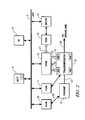
- FIG. 2is a schematic diagram of an exemplary architecture for a controller and powertrain, in accordance with the present invention
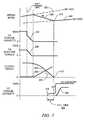
- FIG. 3is an exemplary data graph, in accordance with the present invention.
- FIG. 4is an algorithmic flowchart, in accordance with the present disclosure.
- FIGS. 1 and 2show a system comprising an engine 14 , transmission 10 , control system, and driveline which has been constructed in accordance with an embodiment of the present invention.
- exemplary transmission 10Mechanical aspects of exemplary transmission 10 are disclosed in detail in commonly assigned U.S. Patent Application Publication No. U.S. 2005/0137042 A1, published Jun. 23, 2005, entitled Two-Mode, Compound-Split, Hybrid Electro-Mechanical Transmission having Four Fixed Ratios, which is incorporated herein by reference.
- the exemplary two-mode, compound-split, electro-mechanical hybrid transmission embodying the concepts of the present inventionis depicted in FIG. 1 , and is designated generally by the numeral 10 .
- the hybrid transmission 10has an input member 12 that may be in the nature of a shaft which may be directly driven by an engine 14 .
- a transient torque damper 20is incorporated between the output shaft 18 of the engine 14 and the input member 12 of the hybrid transmission 10 .
- the transient torque damper 20preferably comprises a torque transfer device 77 having characteristics of a damping mechanism and a spring, shown respectively as 78 and 79 .
- the transient torque damper 20permits selective engagement of the engine 14 with the hybrid transmission 10 , but it must be understood that the torque transfer device 77 is not utilized to change, or control, the mode in which the hybrid transmission 10 operates.
- the torque transfer device 77preferably comprises a hydraulically operated friction clutch, referred to as clutch C 5 .
- the engine 14may be any of numerous forms of internal combustion engines, such as a spark-ignition engine or a compression-ignition engine, readily adaptable to provide a power output to the transmission 10 at a range of operating speeds, from idle, at or near 600 revolutions per minute (RPM), to over 6,000 RPM. Irrespective of the means by which the engine 14 is connected to the input member 12 of the transmission 10 , the input member 12 is connected to a planetary gear set 24 in the transmission 10 .
- RPMrevolutions per minute
- the hybrid transmission 10utilizes three planetary-gear sets 24 , 26 and 28 .
- the first planetary gear set 24has an outer gear member 30 that may generally be designated as a ring gear, which circumscribes an inner gear member 32 , generally designated as a sun gear.
- a plurality of planetary gear members 34are rotatably mounted on a carrier 36 such that each planetary gear member 34 meshingly engages both the outer gear member 30 and the inner gear member 32 .
- the second planetary gear set 26also has an outer gear member 38 , generally designated as a ring gear, which circumscribes an inner gear member 40 , generally designated as a sun gear.
- a plurality of planetary gear members 42are rotatably mounted on a carrier 44 such that each planetary gear 42 meshingly engages both the outer gear member 38 and the inner gear member 40 .
- the third planetary gear set 28also has an outer gear member 46 , generally designated as a ring gear, which circumscribes an inner gear member 48 , generally designated as a sun gear.
- a plurality of planetary gear members 50are rotatably mounted on a carrier 52 such that each planetary gear 50 meshingly engages both the outer gear member 46 and the inner gear member 48 .
- Ratios of teeth on ring gears/sun gearsare typically based upon design considerations known to skilled practitioners and outside the scope of the present invention.
- the ring gear/sun gear tooth ratio of the planetary gear set 24is 65/33
- the ring gear/sun gear tooth ratio of the planetary gear set 26is 65/33
- the ring gear/sun gear tooth ratio of the planetary gear set 28is 94/34.
- the three planetary gear sets 24 , 26 and 28each comprise simple planetary gear sets. Furthermore, the first and second planetary gear sets 24 and 26 are compounded in that the inner gear member 32 of the first planetary gear set 24 is conjoined, as through a hub plate gear 54 , to the outer gear member 38 of the second planetary gear set 26 .
- the conjoined inner gear member 32 of the first planetary gear set 24 and the outer gear member 38 of the second planetary gear set 26are continuously connected to a first motor/generator 56 , also referred to as ‘Motor A’.
- the planetary gear sets 24 and 26are further compounded in that the carrier 36 of the first planetary gear set 24 is conjoined, as through a shaft 60 , to the carrier 44 of the second planetary gear set 26 . As such, carriers 36 and 44 of the first and second planetary gear sets 24 and 26 , respectively, are conjoined.
- the shaft 60is also selectively connected to the carrier 52 of the third planetary gear set 28 , as through a torque transfer device 62 which, as will be hereinafter more fully explained, is employed to assist in the selection of the operational modes of the hybrid transmission 10 .
- the carrier 52 of the third planetary gear set 28is connected directly to the transmission output member 64 .
- the output member 64is operably connected to a driveline comprising a gear box 90 or other torque transfer device which provides a torque output to one or more vehicular axles 92 or half-shafts (not shown).
- the axles 92terminate in drive members 96 .
- the drive members 96may be either front or rear wheels of the vehicle on which they are employed, or they may be a drive gear of a track vehicle.
- the drive members 96may have some form of wheel brake 94 associated therewith.
- the drive memberseach have a speed parameter, N WHL , comprising rotational speed of each wheel 96 which is typically measurable with a wheel speed sensor.
- the inner gear member 40 of the second planetary gear set 26is connected to the inner gear member 48 of the third planetary gear set 28 , as through a sleeve shaft 66 that circumscribes shaft 60 .
- the outer gear member 46 of the third planetary gear set 28is selectively connected to ground, represented by the transmission housing 68 , through a torque transfer device 70 .
- Torque transfer device 70is also employed to assist in the selection of the operational modes of the hybrid transmission 10 .
- the sleeve shaft 66is also continuously connected to a second motor/generator 72 , also referred to as ‘Motor B’.
- All the planetary gear sets 24 , 26 and 28 as well as the two motor/generators 56 and 72are coaxially oriented, as about the axially disposed shaft 60 .
- Motor/generators 56 and 72are both of an annular configuration which permits them to circumscribe the three planetary gear sets 24 , 26 and 28 such that the planetary gear sets 24 , 26 and 28 are disposed radially inwardly of the motor/generators 56 and 72 . This configuration assures that the overall envelope, i.e., the circumferential dimension, of the transmission 10 is minimized.
- a torque transfer device 73selectively connects the sun gear 40 with ground, i.e., with transmission housing 68 .
- a torque transfer device 75is operative as a lock-up clutch, locking planetary gear sets 24 , 26 , motors 56 , 72 and the input to rotate as a group, by selectively connecting the sun gear 40 with the carrier 44 .
- the torque transfer devices 62 , 70 , 73 , 75are all friction clutches, respectively referred to as follows: clutch C 1 70 , clutch C 2 62 , clutch C 3 73 , and clutch C 4 75 .
- Each clutchis preferably hydraulically actuated, receiving pressurized hydraulic fluid from a pump. Hydraulic actuation is accomplished using a known hydraulic fluid circuit, which is not described in detail herein.
- the hybrid transmission 10receives input motive torque from a plurality of torque-generative devices, including the engine 14 and the motors/generators 56 and 72 , as a result of energy conversion from fuel or electrical potential stored in an electrical energy storage device (ESD) 74 .
- the ESD 74typically comprises one or more batteries. Other electrical energy and electrochemical energy storage devices that have the ability to store electric power and dispense electric power may be used in place of the batteries without altering the concepts of the present invention.
- the ESD 74is preferably sized based upon factors including regenerative requirements, application issues related to typical road grade and temperature, and propulsion requirements such as emissions, power assist and electric range.
- the ESD 74is high voltage DC-coupled to transmission power inverter module (TPIM) 19 via DC lines or transfer conductors 27 .
- the TPIM 19is an element of the control system described hereinafter with regard to FIG. 2 .
- the TPIM 19communicates with the first motor/generator 56 by transfer conductors 29 , and the TPIM 19 similarly communicates with the second motor/generator 72 by transfer conductors 31 .
- Electrical currentis transferable to or from the ESD 74 in accordance with whether the ESD 74 is being charged or discharged.
- TPIM 19includes the pair of power inverters and respective motor controllers configured to receive motor control commands and control inverter states therefrom for providing motor drive or regeneration functionality.
- the respective inverterreceives current from the DC lines and provides AC current to the respective motor over transfer conductors 29 and 31 .
- the respective inverterreceives AC current from the motor over transfer conductors 29 and 31 and provides current to the DC lines 27 .
- the net DC current provided to or from the invertersdetermines the charge or discharge operating mode of the electrical energy storage device 74 .
- Motor A 56 and Motor B 72are three-phase AC machines and the inverters comprise complementary three-phase power electronics.
- a drive gear 80may be presented from the input member 12 .
- the drive gear 80fixedly connects the input member 12 to the outer gear member 30 of the first planetary gear set 24 , and the drive gear 80 , therefore, receives power from the engine 14 and/or the motor/generators 56 and/or 72 through planetary gear sets 24 and/or 26 .
- the drive gear 80meshingly engages an idler gear 82 which, in turn, meshingly engages a transfer gear 84 that is secured to one end of a shaft 86 .
- the other end of the shaft 86may be secured to a hydraulic/transmission fluid pump and/or power take-off (‘PTO’) unit, designated either individually or collectively at 88 , and comprise an accessory load.
- PTOpower take-off
- FIG. 2a schematic block diagram of the control system, comprising a distributed controller architecture, is shown.
- the elements described hereinaftercomprise a subset of an overall vehicle control architecture, and are operable to provide coordinated system control of the powertrain system described herein.
- the control systemis operable to synthesize pertinent information and inputs, and execute algorithms to control various actuators to achieve control targets, including such parameters as fuel economy, emissions, performance, driveability, and protection of hardware, including batteries of ESD 74 and motors 56 , 72 .
- the distributed controller architectureincludes engine control module (‘ECM’) 23 , transmission control module (‘TCM’) 17 , battery pack control module (‘BPCM’) 21 , and Transmission Power Inverter Module (‘TPIM’) 19 .
- ECMengine control module
- TCMtransmission control module
- BPCMbattery pack control module
- TPIMTransmission Power Inverter Module
- a hybrid control module (‘HCP’) 5provides overarching control and coordination of the aforementioned controllers.
- UIUser Interface
- UI 13operably connected to a plurality of devices through which a vehicle operator typically controls or directs operation of the powertrain, including the transmission 10 .
- Exemplary vehicle operator inputs to the UI 13include an accelerator pedal, a brake pedal, transmission gear selector, and, vehicle speed cruise control.
- Each of the aforementioned controllerscommunicates with other controllers, sensors, and actuators via a local area network (‘LAN’) bus 6 .
- the LAN bus 6allows for structured communication of control parameters and commands between the various controllers.
- the specific communication protocol utilizedis application-specific. By way of example, one communications protocol is the Society of Automotive Engineers standard J1939.
- the LAN bus and appropriate protocolsprovide for robust messaging and multi-controller interfacing between the aforementioned controllers, and other controllers providing functionality such as antilock brakes, traction control, and vehicle stability.
- the HCP 5provides overarching control of the hybrid powertrain system, serving to coordinate operation of the ECM 23 , TCM 17 , TPIM 19 , and BPCM 21 . Based upon various input signals from the UI 13 and the powertrain, the HCP 5 generates various commands, including: an engine torque command, T E — CMD ; clutch torque commands, T CL — N — CMD for the various clutches C 1 , C 2 , C 3 , C 4 of the hybrid transmission 10 ; and motor torque commands, T A — CMD and T B — CMD , for the electrical motors A and B, respectively.
- the ECM 23is operably connected to the engine 14 , and functions to acquire data from a variety of sensors and control a variety of actuators, respectively, of the engine 14 over a plurality of discrete lines collectively shown as aggregate line 35 .
- the ECM 23receives the engine torque command, T E — CMD , from the HCP 5 , and generates a desired axle torque, T AXLE — DES , and an indication of actual engine torque, T E — ACT , which is communicated to the HCP 5 .
- ECM 23is shown generally having bi-directional interface with engine 14 via aggregate line 35 .
- ECM 23Various other parameters that may be sensed by ECM 23 include engine coolant temperature, engine input speed (N E ) to a shaft leading to the transmission, manifold pressure, ambient air temperature, and ambient pressure.
- Various actuators that may be controlled by the ECM 23include fuel injectors, ignition modules, and throttle control modules.
- the TCM 17is operably connected to the transmission 10 and functions to acquire data from a variety of sensors and provide command signals to the transmission.
- Inputs from the TCM 17 to the HCP 5include estimated clutch torques, T CL — N — EST , for each of the clutches C 1 , C 2 , C 3 , and, C 4 and rotational speed, N O , of the output shaft 64 .
- Other actuators and sensorsmay be used to provide additional information from the TCM to the HCP for control purposes.
- the BPCM 21is signally connected one or more sensors operable to monitor electrical current or voltage parameters of the ESD 74 to provide information about the state of the batteries to the HCP 5 .
- Such informationincludes battery state-of-charge, Bat_SOC, and other states of the batteries, including voltage, V BAT , and available power, P BAT — MIN and P BAT — MAX .
- the Transmission Power Inverter Module (TPIM) 19includes a pair of power inverters and motor controllers configured to receive motor control commands and control inverter states therefrom to provide motor drive or regeneration functionality.
- the TPIM 19is operable to generate torque commands for Motors A and B, T A — CMD and T B — CMD , based upon input from the HCP 5 , which is driven by operator input through UI 13 and system operating parameters.
- the predetermined torque commands for Motors A and B, T A — CMD and T B — CMDare adjusted with motor damping torques, T A — DAMP and T B — DAMP , to determine motor torques, T A and T B , which are implemented by the control system, including the TPIM 19 , to control the motors A and B.
- Individual motor speed signals, N A and N B for Motor A and Motor B respectively,are derived by the TPIM 19 from the motor phase information or conventional rotation sensors.
- the TPIM 19determines and communicates motor speeds, N A and N B , to the HCP 5 .
- the electrical energy storage device 74is high-voltage DC-coupled to the TPIM 19 via DC lines 27 . Electrical current is transferable to or from the TPIM 19 in accordance with whether the ESD 74 is being charged or discharged.
- Each of the aforementioned controllersis preferably a general-purpose digital computer generally comprising a microprocessor or central processing unit, read only memory (ROM), random access memory (RAM), electrically programmable read only memory (EPROM), high speed clock, analog to digital (A/D) and digital to analog (D/A) circuitry, and input/output circuitry and devices (I/O) and appropriate signal conditioning and buffer circuitry.
- ROMread only memory
- RAMrandom access memory
- EPROMelectrically programmable read only memory
- high speed clockanalog to digital
- A/Danalog to digital
- D/Adigital to analog
- I/Oinput/output circuitry and devices
- Each controllerhas a set of control algorithms, in the form of algorithmic code 111 comprising resident program instructions and calibrations stored in ROM and executed to provide the respective functions of each computer.
- Information transfer between the various computersis preferably accomplished using the aforementioned LAN 6 .
- Algorithms for control and state estimation in each of the controllersare typically executed during preset loop cycles such that each algorithm is executed at least once each loop cycle.
- Algorithms stored in the non-volatile memory devicesare executed by one of the central processing units and are operable to monitor inputs from the sensing devices and execute control and diagnostic routines to control operation of the respective device, using preset calibrations.
- Loop cyclesare typically executed at regular intervals, for example each 3, 6.25, 15, 25 and 100 milliseconds during ongoing engine and vehicle operation. Alternatively, algorithms may be executed in response to occurrence of an event.
- the supervisory HCP controller 5 and one or more of the other controllersdetermine required transmission output torque, T O .
- Selectively operated components of the hybrid transmission 10are appropriately controlled and manipulated to respond to the operator demand.
- the HCP 5determines an output torque for the transmission, which affects how and when the vehicle accelerates or decelerates. Final vehicle acceleration is affected by other factors, including, e.g., road load, road grade, and vehicle mass.
- the HCP 5monitors the parametric states of the torque-generative devices, and determines the output of the transmission required to arrive at the desired torque output. Under the direction of the HCP 5 , the transmission 10 operates over a range of output speeds from slow to fast in order to meet the operator demand.
- the two-mode, compound-split, electro-mechanical hybrid transmissionincludes output member 64 which receives output power through two distinct gear trains within the transmission 10 , and operates in several transmission operating modes, described with reference now to FIG. 1 , and Table 1, below.
- Motor A 56 or Motor B 72may each operate as electrical motors, designated as MA, MB respectively, and whether motor A 56 is operating as a generator, designated as GA.
- a first mode, or gear trainis selected when the torque transfer device 70 is actuated in order to “ground” the outer gear member 46 of the third planetary gear set 28 .
- a second mode, or gear trainis selected when the torque transfer device 70 is released and the torque transfer device 62 is simultaneously actuated to connect the shaft 60 to the carrier 52 of the third planetary gear set 28 .
- Other factors outside the scope of the inventionaffect when the electrical machines 56 , 72 operate as motors and generators, and are not discussed herein.
- the control systemshown primarily in FIG. 2 , is operable to provide a range of transmission output speeds, N O , of shaft 64 from relatively slow to relatively fast within each mode of operation.
- N Otransmission output speeds
- the combination of two modes with a slow-to-fast output speed range in each modeallows the transmission 10 to propel a vehicle from a stationary condition to highway speeds, and meet various other requirements as previously described.
- the control systemcoordinates operation of the transmission 10 so as to allow synchronized shifts between the modes.
- the first and second modes of operationrefer to circumstances in which the transmission functions are controlled by one clutch, i.e. either clutch C 1 70 or C 2 62 , and by the controlled speed and torque of the motor/generators 56 and 72 . Certain ranges of operation are described below in which fixed ratios are achieved by applying an additional clutch.
- This additional clutchmay be clutch C 3 73 or C 4 75 , as shown in the table, above.
- the rotations of the motor/generators 56 , 72are dependent on internal rotation of the mechanism as defined by the clutching and proportional to the input speed, N I , determined or measured at shaft 12 .
- the motor/generatorsfunction as motors or generators. They are completely independent of engine to output power flow, thereby enabling both to be motors, both to function as generators, or any combination thereof. This allows, for instance, during operation in Fixed Ratio 1 that motive power output from the transmission at shaft 64 is provided by power from the engine and power from Motors A and B, through planetary gear set 28 by accepting power from the energy storage device 74 .
- the transmission operating modecan be switched between Fixed Ratio operation and Mode operation by activating or deactivating one the additional clutches during Mode I or Mode II operation. Determination of operation in fixed ratio or mode control is by algorithms executed by the control system, and is outside the scope of this invention.
- the modes of operationmay overlap the ratio of operation, and selection depends again on the driver's input and response of the vehicle to that input.
- RANGE 1falls primarily within mode I operation when clutches C 1 70 and C 4 75 are engaged.
- RANGE 2falls within mode I and mode II when clutches C 2 62 and C 1 70 are engaged.
- a third fixed ratio rangeis available primarily during mode II when clutches C 2 62 and C 4 75 are engaged, and a fourth fixed ratio range is available during mode II when clutches C 2 62 and C 3 73 are engaged. It is notable that ranges of operation for Mode I and Mode II typically overlap significantly.
- Output of the exemplary powertrain system described hereinaboveis constrained due to mechanical and system limitations.
- the output speed, N O , of the transmission measured at shaft 64is limited due to limitations of engine output speed, N E , measured at shaft 18 , and transmission input speed, N I , measured at shaft 12 , and speed limitations of the electric motors A and B, designated as +/ ⁇ N A , +/ ⁇ N B .
- Output torque, T O , of the transmission 64is similarly limited due to limitations of the engine input torque, T E , and input torque, T I , measured at shaft 12 after the transient torque damper 20 , and torque limitations (T A — MAX , T A — MIN , T B — MAX , T B — MIN ) of the motors A and B 56 , 72 .
- a shiftoccurs in the exemplary transmission due to a change in operator demand for output torque, typically communicated through inputs to the UI 13 , including the accelerator pedal, the brake pedal, the transmission gear selector, and, the vehicle speed cruise control system.
- a change in demand for output torquemay be predicated on a change in external conditions, including, e.g. changes in road grade, road surface conditions, or wind load.
- a change in demand for output torquemay be predicated on a change in powertrain torque demand caused by a controller command to change one of the motor/generators between electrical energy generating mode and torque generating mode.
- the distributed control architectureacts in concert to determine a need for a change in transmission operating gear, and executes the forgoing to effect the change in gear.
- executing a synchronous shift from an initial fixed gear to a final fixed gear in the exemplary transmission of the exemplary powertrain systemcomprises operating the transmission in an initial fixed gear ratio, and, when a shift is commanded, transitioning the transmission to operate in mode operation, as previously described.
- Synchronous shiftingis characterized in that relative speed between reactive clutch plates and friction plates is substantially equal to zero, allowing for signal noise at the sensors. Shifting to Mode operation in this situation is accomplished by deactivating one of the two currently actuated clutches.
- the transmissionoperates in Mode operation, i.e. Mode I or Mode II, until rotational speed of the input shaft 12 is synchronized with a rotational speed of another one of the torque-transfer devices, or clutches.
- the torque-transfer deviceis actuated when the speeds are synchronized, and the transmission is operated at a final fixed gear ratio.
- FIG. 3a graphical depiction of an exemplary synchronous gear shifting event executed by the aforementioned powertrain and driveline system and controller architecture is now described. It is understood that application-specific masses, inertias, friction factors, and other characteristics and parameters of the driveline affect various powertrain and driveline operating states, and therefore the response times and magnitudes are intended to be exemplary, while still descriptive of the overall operation of the powertrain system.
- the X-axiscomprises a time measurement, and the Y-axis comprises various control commands and measured parameters, each plotted as a function of time on the X-axis.
- the line depicted as 302comprises input speed, N I , when the powertrain is operating in a fixed gear, Gear 1 , wherein clutches C 1 and C 4 are actuated.
- input speed N Iis equal to output speed, N O , multiplied by a first gear ratio, GR 1 , i.e., N O *GR 1 .
- the line depicted as 304comprises input speed when the powertrain is operating in fixed gear, Gear 2 , wherein clutches C 1 and C 2 are actuated.
- the distributed control architectureis operable to execute a synchronous speed shift from an initial gear, in this instance, Gear 1 , to a final gear, in this instance Gear 2 , in the exemplary two-mode, compound-split, electro-mechanical hybrid transmission embodying the concepts of the present invention depicted in FIG. 1 .
- the powertrain systemcomprises torque-generative devices 14 , 56 , 72 operable to supply motive torque to the transmission device 10 .
- the transmission device 10comprises a plurality of gears and torque-transfer devices operable to transmit torque between the torque-generative devices 14 , 56 , 72 and the output shaft 64 and drive wheels 96 of the driveline.
- Torque transmissionmay comprise transfer of motive torque from one or more of the torque-generative devices 14 , 56 , 72 to the driveline. Torque transmission may comprise transfer of torque from the drive wheels 96 via the driveline and transmission to one or more of the torque-generative devices 14 , 56 , 72 as a result of a process commonly referred to as engine-braking.
- engine-brakingcomprises transmitting at least a portion of driveline torque resulting from vehicle momentum from the output shaft 64 through torque-transfer devices, i.e., clutches C 1 , C 2 , C 3 , C 4 , to the torque-generative devices 14 , 56 , 72 .
- the transmitted torqueis absorbed by the powertrain in the form of electrical energy generation through the motor/generators 56 , 72 , and, engine braking through the internal combustion engine 14 .
- Reactive torqueis defined as a magnitude of torque transmitted through a torque-transfer device, i.e. a clutch.
- Torque capacityis defined as a maximum amount of torque transmissible across a clutch, and is generally based upon magnitude of clutch pressure and clutch friction. When the magnitude of clutch torque exceeds the torque capacity, clutch slip occurs. The reactive torque is always less than or equal to the torque capacity.
- Clutch pressureis created by controlling magnitude of hydraulic pressure applied to the clutch by the hydraulic circuit of the transmission.
- one or more of the controllersis operable to execute the algorithmic code 111 including algorithms to accomplish the forgoing tasks to achieve synchronous gear shifting.
- the first clutchis clutch C 4 , which is activating the initial gear, in this case Gear 1 or G 1 .
- FIG. 4shows a flowchart depicting the algorithmic code 111 for effecting the synchronous shift graphically depicted in FIG. 3 from an initial fixed gear to a final fixed gear in the hybrid transmission 10 .
- torque capacity of the first clutchshown as line 310
- torque capacityis reduced by reducing hydraulic pressure to the first clutch ( 412 ).
- torque capacityis reduced, it becomes equal to magnitude of reactive torque (Line 308 ) of the first clutch.
- the TPIM controllerIn order to reduce reactive torque to the first clutch C 4 without adversely affecting torque output, T o , of the powertrain, the TPIM controller is commanded to transfer sufficient quantity of electrical energy to electric motors A 56 and B 72 such that their outputs or motive torques, T A and T B , are equal to the reactive torque across the first clutch, C 4 , and thus able to maintain the output torque, T o , at shaft 64 of the transmission ( 414 ).
- Torque outputs of electric motors A 56 and B 72are concurrently increased with continued decrease in clutch torque capacity 310 and reactive torque 308 .
- the reactive torque across Clutch C 4is essentially equal to zero ( 416 ).
- the hydraulic pressure actuating the first clutch, C 4can be turned off with no instantaneous change in torque across clutch plates of the first clutch, C 4 ( 418 ). This action improves clutch durability, and reduces driveline vibrations associated with abrupt clutch actuations and deactivations.
- the torque capacityis reduced by reducing torque pressure, which is accomplished by controlling the hydraulic pump 88 and the clutch pressure control solenoid (not shown) for Clutch C 4 .
- the first clutch, C 4is subsequently deactivated, or disengaged, when the reactive torque is less than a predetermined value.
- the preferable predetermined value for a reactive torque at which the first clutch can be deactivatedis a reactive torque value that is substantially nil ( 416 ).
- Mode operationcomprises operating the electrical motors A 56 and B 72 with a single clutch actuated, in this case C 1 to provide motive torque to the transmission.
- Input shaft 12 speedi.e. N I
- N Iis preferably determined by monitoring speed of shaft 12 , or other parameters, to determine when it is substantially synchronized with rotational speed of the second clutch, in this case C 2 ( 422 ).
- Engine speed, N Eis reduced in a controlled manner by the control system ( 424 ).
- the second clutch, C 2is actuated (point 312 ) ( 432 ).
- To be substantially synchronizedis defined such that a difference in rotational speeds falls within a range of about one radian per second, or, alternatively, within 10 revolutions per second, to accommodate sensor signal noise.
- Synchronously actuating the second clutch, C 2is accomplished as follows.
- rotational speeds of clutches C 2 and C 4depicted as lines 326 and 328 , are known.
- Change in rotational speed of clutch C 2is also known, described as N C2 dot, and depicted as 324 ( 426 ).
- the control systempreferably uses simple algebra to combine the known rotational speed of clutch C 2 at a point in time, and the change in rotational speed of clutch C 2 , N C2 dot, to determine an elapsed period of time necessary for rotational speeds of the reaction and friction plates of clutch C 2 to be substantially equivalent. This is shown as Point 314 .
- rotational speed of the input shaftis substantially synchronized with rotational speed of clutch C 2 ( 430 ). This comprises a point at which actuation of clutch C 2 can be accomplished without inducing torque disturbances in the driveline.
- the time lagis referred to as ‘fill time’, shown as 320 , and is typically in the range of 300 milliseconds ( 428 ).
- the control systemis able to subtract fill time 320 from the point 314 at which speed of the relative rotational speed of the reaction and friction plates of clutch C 2 are substantially synchronous, which is shown as 316 .
- the control systemcommands flow of pressurized hydraulic fluid to the second clutch to increase torque capacity of clutch C 2 .
- Flow of pressurized hydraulic fluidis accomplished by actuating a flow control solenoid contained within the transmission 10 .
- the flow control solenoidis an element of a hydraulic fluid circuit that is operable to deliver pressurized hydraulic fluid to various solenoids and other devices, as commanded by the transmission controller 17 .
- This embodimentdescribes a shift between Gear 1 and Gear 2 . It is understood that other gear changes, both to increase gear ratio and to decrease a gear ratio, are similarly executed and fall within the scope of the invention. It is also understood that modifications in the transmission hardware are allowable within the scope of the invention.
- the inventionhas been described with specific reference to the preferred embodiments and modifications thereto. Further modifications and alterations may occur to others upon reading and understanding the specification. It is intended to include all such modifications and alterations insofar as they come within the scope of the invention.
Landscapes
- Engineering & Computer Science (AREA)
- Chemical & Material Sciences (AREA)
- Combustion & Propulsion (AREA)
- Mechanical Engineering (AREA)
- Transportation (AREA)
- General Engineering & Computer Science (AREA)
- Physics & Mathematics (AREA)
- Fluid Mechanics (AREA)
- Automation & Control Theory (AREA)
- Electric Propulsion And Braking For Vehicles (AREA)
- Hybrid Electric Vehicles (AREA)
- Arrangement Of Transmissions (AREA)
Abstract
Description
| TABLE 1 | ||||
| Transmission Operating Mode | Actuated Clutches | |||
| C1 | 70 | |||
| Fixed Ratio 1 | ||||
| Fixed Ratio 2 | ||||
| Mode II | ||||
| Fixed Ratio 3 | ||||
| Fixed Ratio 4 | ||||
Claims (19)
Priority Applications (3)
| Application Number | Priority Date | Filing Date | Title |
|---|---|---|---|
| US11/417,098US7908063B2 (en) | 2006-05-03 | 2006-05-03 | Synchronous shift execution for hybrid transmission |
| DE102007020353.7ADE102007020353B4 (en) | 2006-05-03 | 2007-04-30 | A method of performing a shift from an initial gear to a final gear in a transmission of a powertrain system and a corresponding manufactured article of manufacture |
| CN2007101024126ACN101067452B (en) | 2006-05-03 | 2007-05-08 | Synchronous shift execution for hybrid transmission |
Applications Claiming Priority (1)
| Application Number | Priority Date | Filing Date | Title |
|---|---|---|---|
| US11/417,098US7908063B2 (en) | 2006-05-03 | 2006-05-03 | Synchronous shift execution for hybrid transmission |
Publications (2)
| Publication Number | Publication Date |
|---|---|
| US20070260381A1 US20070260381A1 (en) | 2007-11-08 |
| US7908063B2true US7908063B2 (en) | 2011-03-15 |
Family
ID=38662158
Family Applications (1)
| Application Number | Title | Priority Date | Filing Date |
|---|---|---|---|
| US11/417,098Expired - Fee RelatedUS7908063B2 (en) | 2006-05-03 | 2006-05-03 | Synchronous shift execution for hybrid transmission |
Country Status (3)
| Country | Link |
|---|---|
| US (1) | US7908063B2 (en) |
| CN (1) | CN101067452B (en) |
| DE (1) | DE102007020353B4 (en) |
Cited By (28)
| Publication number | Priority date | Publication date | Assignee | Title |
|---|---|---|---|---|
| US20090111644A1 (en)* | 2007-10-25 | 2009-04-30 | Gm Global Technology Operations, Inc. | Method and apparatus for clutch torque control in mode and fixed gear for a hybrid powertrain system |
| US20090118082A1 (en)* | 2007-11-04 | 2009-05-07 | Gm Global Technology Operations, Inc. | Method and apparatus to prioritize input acceleration and clutch synchronization performance in neutral for a hybrid powertrain system |
| US20100012405A1 (en)* | 2006-12-12 | 2010-01-21 | Hiroshi Katsuta | Power output apparatus, hybrid vehicle with the same, and method for controlling power output apparatus |
| US20100041512A1 (en)* | 2008-08-15 | 2010-02-18 | Silveri Andrew J | Preventing Gear Shift Cycling of a Hybrid Electric Vehicle |
| US20100227735A1 (en)* | 2009-03-06 | 2010-09-09 | Gm Global Technology Operations, Inc. | Multi-mode hybrid transmission and shift control method for a multi-mode hybrid transmission |
| US20100282530A1 (en)* | 2006-12-08 | 2010-11-11 | Byd Company Limited | Hybrid power output system |
| US20110120788A1 (en)* | 2006-12-25 | 2011-05-26 | Byd Company Limited | Hybrid power output system |
| US20120077639A1 (en)* | 2006-12-30 | 2012-03-29 | Toyota Jidosha Kabushiki Kaisha | Control device for vehicular drive system |
| US8147375B2 (en)* | 2009-05-19 | 2012-04-03 | GM Global Technology Operations LLC | Method of clutch control to start an engine with a hybrid transmission |
| US8337352B2 (en) | 2010-06-22 | 2012-12-25 | Oshkosh Corporation | Electromechanical variable transmission |
| CN103171549A (en)* | 2011-12-22 | 2013-06-26 | 现代自动车株式会社 | Method of improving fuel economy through electric vehicle control |
| US8961364B2 (en) | 2012-05-07 | 2015-02-24 | Ford Global Technologies, Llc | Method and system to manage driveline oscillations with clutch pressure control |
| US9114804B1 (en) | 2013-03-14 | 2015-08-25 | Oshkosh Defense, Llc | Vehicle drive and method with electromechanical variable transmission |
| US9457787B2 (en) | 2012-05-07 | 2016-10-04 | Ford Global Technologies, Llc | Method and system to manage driveline oscillations with motor torque adjustment |
| US9533677B2 (en) | 2014-08-26 | 2017-01-03 | Ford Global Technologies, Llc | Method of transitioning among shift schedules |
| US9616881B2 (en) | 2015-05-22 | 2017-04-11 | Ford Global Technologies, Llc | System and method of controlling a powertrain |
| US9650032B2 (en) | 2015-02-17 | 2017-05-16 | Oshkosh Corporation | Multi-mode electromechanical variable transmission |
| US9651120B2 (en) | 2015-02-17 | 2017-05-16 | Oshkosh Corporation | Multi-mode electromechanical variable transmission |
| US9656659B2 (en) | 2015-02-17 | 2017-05-23 | Oshkosh Corporation | Multi-mode electromechanical variable transmission |
| US20180345781A1 (en)* | 2015-12-04 | 2018-12-06 | Audi Ag | Drive device for a motor vehicle, corresponding motor vehicle and method for operating a drive device |
| US20190236855A1 (en)* | 2018-02-01 | 2019-08-01 | Gkn Automotive Ltd. | Power transfer unit maintenance |
| US10421350B2 (en) | 2015-10-20 | 2019-09-24 | Oshkosh Corporation | Inline electromechanical variable transmission system |
| US10578195B2 (en) | 2015-02-17 | 2020-03-03 | Oshkosh Corporation | Inline electromechanical variable transmission system |
| US10584775B2 (en) | 2015-02-17 | 2020-03-10 | Oshkosh Corporation | Inline electromechanical variable transmission system |
| US10982736B2 (en) | 2015-02-17 | 2021-04-20 | Oshkosh Corporation | Multi-mode electromechanical variable transmission |
| US20210362593A1 (en)* | 2020-05-22 | 2021-11-25 | Dana Belgium N.V. | Vehicle transmission with an inter-axle differential and method for operation of said inter-axle differential |
| US11701959B2 (en) | 2015-02-17 | 2023-07-18 | Oshkosh Corporation | Inline electromechanical variable transmission system |
| US12078231B2 (en) | 2015-02-17 | 2024-09-03 | Oshkosh Corporation | Inline electromechanical variable transmission system |
Families Citing this family (138)
| Publication number | Priority date | Publication date | Assignee | Title |
|---|---|---|---|---|
| US8010263B2 (en)* | 2006-03-22 | 2011-08-30 | GM Global Technology Operations LLC | Method and apparatus for multivariate active driveline damping |
| US8091667B2 (en)* | 2006-06-07 | 2012-01-10 | GM Global Technology Operations LLC | Method for operating a hybrid electric powertrain based on predictive effects upon an electrical energy storage device |
| US7987934B2 (en) | 2007-03-29 | 2011-08-02 | GM Global Technology Operations LLC | Method for controlling engine speed in a hybrid electric vehicle |
| US7996145B2 (en) | 2007-05-03 | 2011-08-09 | GM Global Technology Operations LLC | Method and apparatus to control engine restart for a hybrid powertrain system |
| US7999496B2 (en)* | 2007-05-03 | 2011-08-16 | GM Global Technology Operations LLC | Method and apparatus to determine rotational position of an electrical machine |
| US7991519B2 (en) | 2007-05-14 | 2011-08-02 | GM Global Technology Operations LLC | Control architecture and method to evaluate engine off operation of a hybrid powertrain system operating in a continuously variable mode |
| US8390240B2 (en) | 2007-08-06 | 2013-03-05 | GM Global Technology Operations LLC | Absolute position sensor for field-oriented control of an induction motor |
| US8265813B2 (en)* | 2007-09-11 | 2012-09-11 | GM Global Technology Operations LLC | Method and control architecture for optimization of engine fuel-cutoff selection and engine input torque for a hybrid powertrain system |
| US7988591B2 (en)* | 2007-09-11 | 2011-08-02 | GM Global Technology Operations LLC | Control architecture and method for one-dimensional optimization of input torque and motor torque in fixed gear for a hybrid powertrain system |
| US7983823B2 (en) | 2007-09-11 | 2011-07-19 | GM Global Technology Operations LLC | Method and control architecture for selection of optimal engine input torque for a powertrain system |
| US8027771B2 (en)* | 2007-09-13 | 2011-09-27 | GM Global Technology Operations LLC | Method and apparatus to monitor an output speed sensor during operation of an electro-mechanical transmission |
| US7867135B2 (en) | 2007-09-26 | 2011-01-11 | GM Global Technology Operations LLC | Electro-mechanical transmission control system |
| US8062170B2 (en)* | 2007-09-28 | 2011-11-22 | GM Global Technology Operations LLC | Thermal protection of an electric drive system |
| US8234048B2 (en) | 2007-10-19 | 2012-07-31 | GM Global Technology Operations LLC | Method and system for inhibiting operation in a commanded operating range state for a transmission of a powertrain system |
| US8060267B2 (en) | 2007-10-23 | 2011-11-15 | GM Global Technology Operations LLC | Method for controlling power flow within a powertrain system |
| US9140337B2 (en) | 2007-10-23 | 2015-09-22 | GM Global Technology Operations LLC | Method for model based clutch control and torque estimation |
| US8265821B2 (en) | 2007-10-25 | 2012-09-11 | GM Global Technology Operations LLC | Method for determining a voltage level across an electric circuit of a powertrain |
| US8296027B2 (en) | 2007-10-25 | 2012-10-23 | GM Global Technology Operations LLC | Method and apparatus to control off-going clutch torque during torque phase for a hybrid powertrain system |
| US8335623B2 (en) | 2007-10-25 | 2012-12-18 | GM Global Technology Operations LLC | Method and apparatus for remediation of and recovery from a clutch slip event in a hybrid powertrain system |
| US8118122B2 (en) | 2007-10-25 | 2012-02-21 | GM Global Technology Operations LLC | Method and system for monitoring signal integrity in a distributed controls system |
| US8167773B2 (en) | 2007-10-26 | 2012-05-01 | GM Global Technology Operations LLC | Method and apparatus to control motor cooling in an electro-mechanical transmission |
| US7985154B2 (en) | 2007-10-26 | 2011-07-26 | GM Global Technology Operations LLC | Method and apparatus to control hydraulic pressure for component lubrication in an electro-mechanical transmission |
| US9097337B2 (en) | 2007-10-26 | 2015-08-04 | GM Global Technology Operations LLC | Method and apparatus to control hydraulic line pressure in an electro-mechanical transmission |
| US8560191B2 (en) | 2007-10-26 | 2013-10-15 | GM Global Technology Operations LLC | Method and apparatus to control clutch pressures in an electro-mechanical transmission |
| US8406945B2 (en) | 2007-10-26 | 2013-03-26 | GM Global Technology Operations LLC | Method and apparatus to control logic valves for hydraulic flow control in an electro-mechanical transmission |
| US8303463B2 (en) | 2007-10-26 | 2012-11-06 | GM Global Technology Operations LLC | Method and apparatus to control clutch fill pressure in an electro-mechanical transmission |
| US8204702B2 (en) | 2007-10-26 | 2012-06-19 | GM Global Technology Operations LLC | Method for estimating battery life in a hybrid powertrain |
| US8548703B2 (en) | 2007-10-26 | 2013-10-01 | GM Global Technology Operations LLC | Method and apparatus to determine clutch slippage in an electro-mechanical transmission |
| US8062174B2 (en) | 2007-10-27 | 2011-11-22 | GM Global Technology Operations LLC | Method and apparatus to control clutch stroke volume in an electro-mechanical transmission |
| US8428816B2 (en) | 2007-10-27 | 2013-04-23 | GM Global Technology Operations LLC | Method and apparatus for monitoring software and signal integrity in a distributed control module system for a powertrain system |
| US8244426B2 (en) | 2007-10-27 | 2012-08-14 | GM Global Technology Operations LLC | Method and apparatus for monitoring processor integrity in a distributed control module system for a powertrain system |
| US8099219B2 (en) | 2007-10-27 | 2012-01-17 | GM Global Technology Operations LLC | Method and apparatus for securing an operating range state mechanical transmission |
| US8112194B2 (en) | 2007-10-29 | 2012-02-07 | GM Global Technology Operations LLC | Method and apparatus for monitoring regenerative operation in a hybrid powertrain system |
| US8282526B2 (en)* | 2007-10-29 | 2012-10-09 | GM Global Technology Operations LLC | Method and apparatus to create a pseudo torque phase during oncoming clutch engagement to prevent clutch slip for a hybrid powertrain system |
| US8170762B2 (en) | 2007-10-29 | 2012-05-01 | GM Global Technology Operations LLC | Method and apparatus to control operation of a hydraulic pump for an electro-mechanical transmission |
| US8209098B2 (en) | 2007-10-29 | 2012-06-26 | GM Global Technology Operations LLC | Method and apparatus for monitoring a transmission range selector in a hybrid powertrain transmission |
| US8290681B2 (en) | 2007-10-29 | 2012-10-16 | GM Global Technology Operations LLC | Method and apparatus to produce a smooth input speed profile in mode for a hybrid powertrain system |
| US8489293B2 (en) | 2007-10-29 | 2013-07-16 | GM Global Technology Operations LLC | Method and apparatus to control input speed profile during inertia speed phase for a hybrid powertrain system |
| US8095254B2 (en) | 2007-10-29 | 2012-01-10 | GM Global Technology Operations LLC | Method for determining a power constraint for controlling a powertrain system |
| US8078371B2 (en) | 2007-10-31 | 2011-12-13 | GM Global Technology Operations LLC | Method and apparatus to monitor output of an electro-mechanical transmission |
| US8073602B2 (en) | 2007-11-01 | 2011-12-06 | GM Global Technology Operations LLC | System constraints method of controlling operation of an electro-mechanical transmission with an additional constraint range |
| US8035324B2 (en) | 2007-11-01 | 2011-10-11 | GM Global Technology Operations LLC | Method for determining an achievable torque operating region for a transmission |
| US8556011B2 (en) | 2007-11-01 | 2013-10-15 | GM Global Technology Operations LLC | Prediction strategy for thermal management and protection of power electronic hardware |
| US8145375B2 (en) | 2007-11-01 | 2012-03-27 | GM Global Technology Operations LLC | System constraints method of determining minimum and maximum torque limits for an electro-mechanical powertrain system |
| US7977896B2 (en) | 2007-11-01 | 2011-07-12 | GM Global Technology Operations LLC | Method of determining torque limit with motor torque and battery power constraints |
| US8133151B2 (en) | 2007-11-02 | 2012-03-13 | GM Global Technology Operations LLC | System constraints method of controlling operation of an electro-mechanical transmission with an additional constraint |
| US8847426B2 (en) | 2007-11-02 | 2014-09-30 | GM Global Technology Operations LLC | Method for managing electric power in a powertrain system |
| US8121765B2 (en) | 2007-11-02 | 2012-02-21 | GM Global Technology Operations LLC | System constraints method of controlling operation of an electro-mechanical transmission with two external input torque ranges |
| US8224539B2 (en) | 2007-11-02 | 2012-07-17 | GM Global Technology Operations LLC | Method for altitude-compensated transmission shift scheduling |
| US8200403B2 (en) | 2007-11-02 | 2012-06-12 | GM Global Technology Operations LLC | Method for controlling input torque provided to a transmission |
| US8287426B2 (en) | 2007-11-02 | 2012-10-16 | GM Global Technology Operations LLC | Method for controlling voltage within a powertrain system |
| US8121767B2 (en) | 2007-11-02 | 2012-02-21 | GM Global Technology Operations LLC | Predicted and immediate output torque control architecture for a hybrid powertrain system |
| US8825320B2 (en) | 2007-11-02 | 2014-09-02 | GM Global Technology Operations LLC | Method and apparatus for developing a deceleration-based synchronous shift schedule |
| US8585540B2 (en) | 2007-11-02 | 2013-11-19 | GM Global Technology Operations LLC | Control system for engine torque management for a hybrid powertrain system |
| US8131437B2 (en) | 2007-11-02 | 2012-03-06 | GM Global Technology Operations LLC | Method for operating a powertrain system to transition between engine states |
| US8135526B2 (en) | 2007-11-03 | 2012-03-13 | GM Global Technology Operations LLC | Method for controlling regenerative braking and friction braking |
| US8010247B2 (en) | 2007-11-03 | 2011-08-30 | GM Global Technology Operations LLC | Method for operating an engine in a hybrid powertrain system |
| US8285431B2 (en) | 2007-11-03 | 2012-10-09 | GM Global Technology Operations LLC | Optimal selection of hybrid range state and/or input speed with a blended braking system in a hybrid electric vehicle |
| US8224514B2 (en) | 2007-11-03 | 2012-07-17 | GM Global Technology Operations LLC | Creation and depletion of short term power capability in a hybrid electric vehicle |
| US8204664B2 (en) | 2007-11-03 | 2012-06-19 | GM Global Technology Operations LLC | Method for controlling regenerative braking in a vehicle |
| US8406970B2 (en) | 2007-11-03 | 2013-03-26 | GM Global Technology Operations LLC | Method for stabilization of optimal input speed in mode for a hybrid powertrain system |
| US8296021B2 (en) | 2007-11-03 | 2012-10-23 | GM Global Technology Operations LLC | Method for determining constraints on input torque in a hybrid transmission |
| US8002667B2 (en) | 2007-11-03 | 2011-08-23 | GM Global Technology Operations LLC | Method for determining input speed acceleration limits in a hybrid transmission |
| US8868252B2 (en) | 2007-11-03 | 2014-10-21 | GM Global Technology Operations LLC | Control architecture and method for two-dimensional optimization of input speed and input power including search windowing |
| US8155814B2 (en) | 2007-11-03 | 2012-04-10 | GM Global Technology Operations LLC | Method of operating a vehicle utilizing regenerative braking |
| US8260511B2 (en) | 2007-11-03 | 2012-09-04 | GM Global Technology Operations LLC | Method for stabilization of mode and fixed gear for a hybrid powertrain system |
| US8068966B2 (en) | 2007-11-03 | 2011-11-29 | GM Global Technology Operations LLC | Method for monitoring an auxiliary pump for a hybrid powertrain |
| US8098041B2 (en) | 2007-11-04 | 2012-01-17 | GM Global Technology Operations LLC | Method of charging a powertrain |
| US8095282B2 (en) | 2007-11-04 | 2012-01-10 | GM Global Technology Operations LLC | Method and apparatus for soft costing input speed and output speed in mode and fixed gear as function of system temperatures for cold and hot operation for a hybrid powertrain system |
| US8204656B2 (en) | 2007-11-04 | 2012-06-19 | GM Global Technology Operations LLC | Control architecture for output torque shaping and motor torque determination for a hybrid powertrain system |
| US9008926B2 (en)* | 2007-11-04 | 2015-04-14 | GM Global Technology Operations LLC | Control of engine torque during upshift and downshift torque phase for a hybrid powertrain system |
| US8346449B2 (en) | 2007-11-04 | 2013-01-01 | GM Global Technology Operations LLC | Method and apparatus to provide necessary output torque reserve by selection of hybrid range state and input speed for a hybrid powertrain system |
| US8067908B2 (en) | 2007-11-04 | 2011-11-29 | GM Global Technology Operations LLC | Method for electric power boosting in a powertrain system |
| US8145397B2 (en) | 2007-11-04 | 2012-03-27 | GM Global Technology Operations LLC | Optimal selection of blended braking capacity for a hybrid electric vehicle |
| US8138703B2 (en) | 2007-11-04 | 2012-03-20 | GM Global Technology Operations LLC | Method and apparatus for constraining output torque in a hybrid powertrain system |
| US8214093B2 (en) | 2007-11-04 | 2012-07-03 | GM Global Technology Operations LLC | Method and apparatus to prioritize transmission output torque and input acceleration for a hybrid powertrain system |
| US8248023B2 (en) | 2007-11-04 | 2012-08-21 | GM Global Technology Operations LLC | Method of externally charging a powertrain |
| US8002665B2 (en) | 2007-11-04 | 2011-08-23 | GM Global Technology Operations LLC | Method for controlling power actuators in a hybrid powertrain system |
| US8818660B2 (en) | 2007-11-04 | 2014-08-26 | GM Global Technology Operations LLC | Method for managing lash in a driveline |
| US8118903B2 (en) | 2007-11-04 | 2012-02-21 | GM Global Technology Operations LLC | Method for preferential selection of modes and gear with inertia effects for a hybrid powertrain system |
| US8000866B2 (en) | 2007-11-04 | 2011-08-16 | GM Global Technology Operations LLC | Engine control system for torque management in a hybrid powertrain system |
| US8214120B2 (en) | 2007-11-04 | 2012-07-03 | GM Global Technology Operations LLC | Method to manage a high voltage system in a hybrid powertrain system |
| US8112192B2 (en) | 2007-11-04 | 2012-02-07 | GM Global Technology Operations LLC | Method for managing electric power within a powertrain system |
| US8112206B2 (en) | 2007-11-04 | 2012-02-07 | GM Global Technology Operations LLC | Method for controlling a powertrain system based upon energy storage device temperature |
| US8414449B2 (en) | 2007-11-04 | 2013-04-09 | GM Global Technology Operations LLC | Method and apparatus to perform asynchronous shifts with oncoming slipping clutch torque for a hybrid powertrain system |
| US8630776B2 (en) | 2007-11-04 | 2014-01-14 | GM Global Technology Operations LLC | Method for controlling an engine of a hybrid powertrain in a fuel enrichment mode |
| US7988594B2 (en) | 2007-11-04 | 2011-08-02 | GM Global Technology Operations LLC | Method for load-based stabilization of mode and fixed gear operation of a hybrid powertrain system |
| US8374758B2 (en) | 2007-11-04 | 2013-02-12 | GM Global Technology Operations LLC | Method for developing a trip cost structure to understand input speed trip for a hybrid powertrain system |
| US8135532B2 (en) | 2007-11-04 | 2012-03-13 | GM Global Technology Operations LLC | Method for controlling output power of an energy storage device in a powertrain system |
| US8200383B2 (en) | 2007-11-04 | 2012-06-12 | GM Global Technology Operations LLC | Method for controlling a powertrain system based upon torque machine temperature |
| US8897975B2 (en) | 2007-11-04 | 2014-11-25 | GM Global Technology Operations LLC | Method for controlling a powertrain system based on penalty costs |
| US8079933B2 (en) | 2007-11-04 | 2011-12-20 | GM Global Technology Operations LLC | Method and apparatus to control engine torque to peak main pressure for a hybrid powertrain system |
| US8126624B2 (en) | 2007-11-04 | 2012-02-28 | GM Global Technology Operations LLC | Method for selection of optimal mode and gear and input speed for preselect or tap up/down operation |
| US8396634B2 (en) | 2007-11-04 | 2013-03-12 | GM Global Technology Operations LLC | Method and apparatus for maximum and minimum output torque performance by selection of hybrid range state and input speed for a hybrid powertrain system |
| US8221285B2 (en) | 2007-11-04 | 2012-07-17 | GM Global Technology Operations LLC | Method and apparatus to offload offgoing clutch torque with asynchronous oncoming clutch torque, engine and motor torque for a hybrid powertrain system |
| US8214114B2 (en) | 2007-11-04 | 2012-07-03 | GM Global Technology Operations LLC | Control of engine torque for traction and stability control events for a hybrid powertrain system |
| US8594867B2 (en) | 2007-11-04 | 2013-11-26 | GM Global Technology Operations LLC | System architecture for a blended braking system in a hybrid powertrain system |
| US8504259B2 (en) | 2007-11-04 | 2013-08-06 | GM Global Technology Operations LLC | Method for determining inertia effects for a hybrid powertrain system |
| US8494732B2 (en) | 2007-11-04 | 2013-07-23 | GM Global Technology Operations LLC | Method for determining a preferred engine operation in a hybrid powertrain system during blended braking |
| US8121766B2 (en) | 2007-11-04 | 2012-02-21 | GM Global Technology Operations LLC | Method for operating an internal combustion engine to transmit power to a driveline |
| US8160761B2 (en) | 2007-11-05 | 2012-04-17 | GM Global Technology Operations LLC | Method for predicting an operator torque request of a hybrid powertrain system |
| US8165777B2 (en) | 2007-11-05 | 2012-04-24 | GM Global Technology Operations LLC | Method to compensate for transmission spin loss for a hybrid powertrain system |
| US8321100B2 (en) | 2007-11-05 | 2012-11-27 | GM Global Technology Operations LLC | Method and apparatus for dynamic output torque limiting for a hybrid powertrain system |
| US8099204B2 (en) | 2007-11-05 | 2012-01-17 | GM Global Technology Operatons LLC | Method for controlling electric boost in a hybrid powertrain |
| US8249766B2 (en) | 2007-11-05 | 2012-08-21 | GM Global Technology Operations LLC | Method of determining output torque limits of a hybrid transmission operating in a fixed gear operating range state |
| US8219303B2 (en) | 2007-11-05 | 2012-07-10 | GM Global Technology Operations LLC | Method for operating an internal combustion engine for a hybrid powertrain system |
| US8070647B2 (en) | 2007-11-05 | 2011-12-06 | GM Global Technology Operations LLC | Method and apparatus for adapting engine operation in a hybrid powertrain system for active driveline damping |
| US8285432B2 (en) | 2007-11-05 | 2012-10-09 | GM Global Technology Operations LLC | Method and apparatus for developing a control architecture for coordinating shift execution and engine torque control |
| US8155815B2 (en) | 2007-11-05 | 2012-04-10 | Gm Global Technology Operation Llc | Method and apparatus for securing output torque in a distributed control module system for a powertrain system |
| US8121768B2 (en) | 2007-11-05 | 2012-02-21 | GM Global Technology Operations LLC | Method for controlling a hybrid powertrain system based upon hydraulic pressure and clutch reactive torque capacity |
| US8448731B2 (en) | 2007-11-05 | 2013-05-28 | GM Global Technology Operations LLC | Method and apparatus for determination of fast actuating engine torque for a hybrid powertrain system |
| US8112207B2 (en) | 2007-11-05 | 2012-02-07 | GM Global Technology Operations LLC | Method and apparatus to determine a preferred output torque for operating a hybrid transmission in a continuously variable mode |
| US8285462B2 (en) | 2007-11-05 | 2012-10-09 | GM Global Technology Operations LLC | Method and apparatus to determine a preferred output torque in mode and fixed gear operation with clutch torque constraints for a hybrid powertrain system |
| US8135519B2 (en) | 2007-11-05 | 2012-03-13 | GM Global Technology Operations LLC | Method and apparatus to determine a preferred output torque for operating a hybrid transmission in a fixed gear operating range state |
| US8229633B2 (en) | 2007-11-05 | 2012-07-24 | GM Global Technology Operations LLC | Method for operating a powertrain system to control engine stabilization |
| US8073601B2 (en) | 2007-11-05 | 2011-12-06 | GM Global Technology Operations LLC | Method for preferential selection of mode and gear and input speed based on multiple engine state fueling costs for a hybrid powertrain system |
| US8179127B2 (en) | 2007-11-06 | 2012-05-15 | GM Global Technology Operations LLC | Method and apparatus to monitor position of a rotatable shaft |
| US8281885B2 (en) | 2007-11-06 | 2012-10-09 | GM Global Technology Operations LLC | Method and apparatus to monitor rotational speeds in an electro-mechanical transmission |
| US8073610B2 (en) | 2007-11-07 | 2011-12-06 | GM Global Technology Operations LLC | Method and apparatus to control warm-up of an exhaust aftertreatment system for a hybrid powertrain |
| US8224544B2 (en)* | 2007-11-07 | 2012-07-17 | GM Global Technology Operations LLC | Method and apparatus to control launch of a vehicle having an electro-mechanical transmission |
| US8195349B2 (en) | 2007-11-07 | 2012-06-05 | GM Global Technology Operations LLC | Method for predicting a speed output of a hybrid powertrain system |
| US8267837B2 (en) | 2007-11-07 | 2012-09-18 | GM Global Technology Operations LLC | Method and apparatus to control engine temperature for a hybrid powertrain |
| US8209097B2 (en) | 2007-11-07 | 2012-06-26 | GM Global Technology Operations LLC | Method and control architecture to determine motor torque split in fixed gear operation for a hybrid powertrain system |
| US8271173B2 (en) | 2007-11-07 | 2012-09-18 | GM Global Technology Operations LLC | Method and apparatus for controlling a hybrid powertrain system |
| US8433486B2 (en) | 2007-11-07 | 2013-04-30 | GM Global Technology Operations LLC | Method and apparatus to determine a preferred operating point for an engine of a powertrain system using an iterative search |
| US8005632B2 (en)* | 2007-11-07 | 2011-08-23 | GM Global Technology Operations LLC | Method and apparatus for detecting faults in a current sensing device |
| US8277363B2 (en) | 2007-11-07 | 2012-10-02 | GM Global Technology Operations LLC | Method and apparatus to control temperature of an exhaust aftertreatment system for a hybrid powertrain |
| HUP0800048A2 (en)* | 2008-01-25 | 2009-08-28 | Istvan Dr Janosi | Frying device for making fried cake specially for household |
| DE102008000639A1 (en)* | 2008-03-13 | 2009-09-17 | Zf Friedrichshafen Ag | Arrangement for transmitting data and / or signals in a transmission |
| US8162085B2 (en)* | 2008-12-24 | 2012-04-24 | GM Global Technologies Operations LLC | Hydro-mechanical clutch for a hybrid transmission and method for operating the same |
| US8412426B2 (en)* | 2009-03-06 | 2013-04-02 | GM Global Technology Operations LLC | Multi-mode hybrid transmission and method for performing a quasi-asynchronous shift in a hybrid transmission |
| DE102009059934A1 (en)* | 2009-12-22 | 2011-06-30 | Volkswagen AG, 38440 | Gear arrangement and motor vehicle |
| US8412397B2 (en)* | 2011-02-10 | 2013-04-02 | GM Global Technology Operations LLC | Clutch fill command based on clutch slip speed profile synchronization prediction |
| US8827865B2 (en) | 2011-08-31 | 2014-09-09 | GM Global Technology Operations LLC | Control system for a hybrid powertrain system |
| US9046171B2 (en)* | 2011-12-06 | 2015-06-02 | GM Global Technology Operations LLC | Method to control a hybrid transmission using on-off switches controlling hydraulic flow to a clutch |
| WO2013084292A1 (en)* | 2011-12-06 | 2013-06-13 | トヨタ自動車株式会社 | Gear shift instruction device |
| US8801567B2 (en) | 2012-02-17 | 2014-08-12 | GM Global Technology Operations LLC | Method and apparatus for executing an asynchronous clutch-to-clutch shift in a hybrid transmission |
| EP3878673B1 (en)* | 2018-11-08 | 2023-04-19 | Schaeffler Technologies AG & Co. KG | Hybrid power module and vehicle |
Citations (11)
| Publication number | Priority date | Publication date | Assignee | Title |
|---|---|---|---|---|
| US5833570A (en)* | 1996-05-28 | 1998-11-10 | Toyota Jidosha Kabushiki Kaisha | Vehicle transmission shift control apparatus wherein torque of motor connected to automatic transmission is controlled to reduce shifting shock of transmission |
| US5931757A (en)* | 1998-06-24 | 1999-08-03 | General Motors Corporation | Two-mode, compound-split electro-mechanical vehicular transmission |
| US6019699A (en)* | 1998-02-04 | 2000-02-01 | Toyota Jidosha Kabushiki Kaisha | Synchronized coast downshift control for hybrid vehicles |
| US6351700B1 (en)* | 1999-06-28 | 2002-02-26 | Nissan Motor Co., Ltd. | Speed change controller and control method of infinite speed ratio continuously variable transmission |
| US6551208B1 (en)* | 2001-10-18 | 2003-04-22 | General Motors Corporation | Three-mode, compound-split, electrically-variable transmission |
| US6662893B2 (en)* | 2000-09-19 | 2003-12-16 | Nissan Motor Co., Ltd. | Forward and aft torque distribution control system for 4WD vehicle and method |
| US20050080540A1 (en)* | 2003-10-14 | 2005-04-14 | Steinmetz Todd M. | Synchronous shift control in an electrically variable transmission |
| US20050101435A1 (en)* | 2003-11-12 | 2005-05-12 | Ronald Cowan | Control of powertrain smoothness using output torque sensing and input torque control |
| US20050182543A1 (en)* | 2004-02-14 | 2005-08-18 | Sah Jy-Jen F. | Shift through neutral control in an electrically variable transmission |
| US20060003863A1 (en)* | 2004-07-01 | 2006-01-05 | Atsushi Tabata | Control device for vehicular drive system |
| US20080004779A1 (en)* | 2006-06-30 | 2008-01-03 | Sah Jy-Jen F | Apparatus and method to control transmission torque output during a gear-to-gear shift |
Family Cites Families (2)
| Publication number | Priority date | Publication date | Assignee | Title |
|---|---|---|---|---|
| PL208582B1 (en)* | 2002-12-25 | 2011-05-31 | Toyota Motor Co Ltd | Control device of hybrid drive unit |
| US6953409B2 (en)* | 2003-12-19 | 2005-10-11 | General Motors Corporation | Two-mode, compound-split, hybrid electro-mechanical transmission having four fixed ratios |
- 2006
- 2006-05-03USUS11/417,098patent/US7908063B2/ennot_activeExpired - Fee Related
- 2007
- 2007-04-30DEDE102007020353.7Apatent/DE102007020353B4/ennot_activeExpired - Fee Related
- 2007-05-08CNCN2007101024126Apatent/CN101067452B/ennot_activeExpired - Fee Related
Patent Citations (11)
| Publication number | Priority date | Publication date | Assignee | Title |
|---|---|---|---|---|
| US5833570A (en)* | 1996-05-28 | 1998-11-10 | Toyota Jidosha Kabushiki Kaisha | Vehicle transmission shift control apparatus wherein torque of motor connected to automatic transmission is controlled to reduce shifting shock of transmission |
| US6019699A (en)* | 1998-02-04 | 2000-02-01 | Toyota Jidosha Kabushiki Kaisha | Synchronized coast downshift control for hybrid vehicles |
| US5931757A (en)* | 1998-06-24 | 1999-08-03 | General Motors Corporation | Two-mode, compound-split electro-mechanical vehicular transmission |
| US6351700B1 (en)* | 1999-06-28 | 2002-02-26 | Nissan Motor Co., Ltd. | Speed change controller and control method of infinite speed ratio continuously variable transmission |
| US6662893B2 (en)* | 2000-09-19 | 2003-12-16 | Nissan Motor Co., Ltd. | Forward and aft torque distribution control system for 4WD vehicle and method |
| US6551208B1 (en)* | 2001-10-18 | 2003-04-22 | General Motors Corporation | Three-mode, compound-split, electrically-variable transmission |
| US20050080540A1 (en)* | 2003-10-14 | 2005-04-14 | Steinmetz Todd M. | Synchronous shift control in an electrically variable transmission |
| US20050101435A1 (en)* | 2003-11-12 | 2005-05-12 | Ronald Cowan | Control of powertrain smoothness using output torque sensing and input torque control |
| US20050182543A1 (en)* | 2004-02-14 | 2005-08-18 | Sah Jy-Jen F. | Shift through neutral control in an electrically variable transmission |
| US20060003863A1 (en)* | 2004-07-01 | 2006-01-05 | Atsushi Tabata | Control device for vehicular drive system |
| US20080004779A1 (en)* | 2006-06-30 | 2008-01-03 | Sah Jy-Jen F | Apparatus and method to control transmission torque output during a gear-to-gear shift |
Cited By (69)
| Publication number | Priority date | Publication date | Assignee | Title |
|---|---|---|---|---|
| US8540601B2 (en)* | 2006-12-08 | 2013-09-24 | Byd Co. Ltd. | Hybrid power output system |
| US20100282530A1 (en)* | 2006-12-08 | 2010-11-11 | Byd Company Limited | Hybrid power output system |
| US20100012405A1 (en)* | 2006-12-12 | 2010-01-21 | Hiroshi Katsuta | Power output apparatus, hybrid vehicle with the same, and method for controlling power output apparatus |
| US8122983B2 (en)* | 2006-12-12 | 2012-02-28 | Toyota Jidosha Kabushiki Kaisha | Power output apparatus, hybrid vehicle with the same, and method for controlling power output apparatus |
| US20110120788A1 (en)* | 2006-12-25 | 2011-05-26 | Byd Company Limited | Hybrid power output system |
| US8307924B2 (en)* | 2006-12-25 | 2012-11-13 | Byd Co. Ltd. | Hybrid power output system |
| US8562482B2 (en)* | 2006-12-30 | 2013-10-22 | Toyota Jidosha Kabushiki Kaisha | Control device for vehicular drive system |
| US20120077639A1 (en)* | 2006-12-30 | 2012-03-29 | Toyota Jidosha Kabushiki Kaisha | Control device for vehicular drive system |
| US20090111644A1 (en)* | 2007-10-25 | 2009-04-30 | Gm Global Technology Operations, Inc. | Method and apparatus for clutch torque control in mode and fixed gear for a hybrid powertrain system |
| US8187145B2 (en)* | 2007-10-25 | 2012-05-29 | GM Global Technology Operations LLC | Method and apparatus for clutch torque control in mode and fixed gear for a hybrid powertrain system |
| US20090118082A1 (en)* | 2007-11-04 | 2009-05-07 | Gm Global Technology Operations, Inc. | Method and apparatus to prioritize input acceleration and clutch synchronization performance in neutral for a hybrid powertrain system |
| US8092339B2 (en)* | 2007-11-04 | 2012-01-10 | GM Global Technology Operations LLC | Method and apparatus to prioritize input acceleration and clutch synchronization performance in neutral for a hybrid powertrain system |
| US8257222B2 (en)* | 2008-08-15 | 2012-09-04 | Ford Global Technologies, Llc | Preventing gear shift cycling of a hybrid electric vehicle |
| US20100041512A1 (en)* | 2008-08-15 | 2010-02-18 | Silveri Andrew J | Preventing Gear Shift Cycling of a Hybrid Electric Vehicle |
| US8287427B2 (en)* | 2009-03-06 | 2012-10-16 | GM Global Technology Operations LLC | Multi-mode hybrid transmission and shift control method for a multi-mode hybrid transmission |
| US20100227735A1 (en)* | 2009-03-06 | 2010-09-09 | Gm Global Technology Operations, Inc. | Multi-mode hybrid transmission and shift control method for a multi-mode hybrid transmission |
| US8147375B2 (en)* | 2009-05-19 | 2012-04-03 | GM Global Technology Operations LLC | Method of clutch control to start an engine with a hybrid transmission |
| US8864613B2 (en) | 2010-06-22 | 2014-10-21 | Oshkosh Corporation | Electromechanical variable transmission |
| US10457134B2 (en) | 2010-06-22 | 2019-10-29 | Oshkosh Defense, Llc | Electromechanical variable transmission |
| US10843549B2 (en) | 2010-06-22 | 2020-11-24 | Oshkosh Defense, Llc | Electromechanical variable transmission |
| US10029556B2 (en) | 2010-06-22 | 2018-07-24 | Oshkosh Defense, Llc | Electromechanical variable transmission |
| US8337352B2 (en) | 2010-06-22 | 2012-12-25 | Oshkosh Corporation | Electromechanical variable transmission |
| US9428042B2 (en) | 2010-06-22 | 2016-08-30 | Oshkosh Defense, Llc | Electromechanical variable transmission |
| US20130166120A1 (en)* | 2011-12-22 | 2013-06-27 | Kia Motors Corporation | Method of improving fuel economy through electric vehicle control of a hybrid vehicle having various modes |
| CN103171549A (en)* | 2011-12-22 | 2013-06-26 | 现代自动车株式会社 | Method of improving fuel economy through electric vehicle control |
| US8965611B2 (en)* | 2011-12-22 | 2015-02-24 | Hyundai Motor Company | Method of improving fuel economy through electric vehicle control of a hybrid vehicle having various modes |
| CN103171549B (en)* | 2011-12-22 | 2017-04-12 | 现代自动车株式会社 | Method of improving fuel economy through electric vehicle control |
| US8961364B2 (en) | 2012-05-07 | 2015-02-24 | Ford Global Technologies, Llc | Method and system to manage driveline oscillations with clutch pressure control |
| US9457787B2 (en) | 2012-05-07 | 2016-10-04 | Ford Global Technologies, Llc | Method and system to manage driveline oscillations with motor torque adjustment |
| US12214770B2 (en) | 2013-03-14 | 2025-02-04 | Oshkosh Defense, Llc | Drive train for a vehicle |
| US9452750B2 (en) | 2013-03-14 | 2016-09-27 | Oshkosh Defense, Llc | Methods, systems, and vehicles with electromechanical variable transmission |
| US11827207B2 (en) | 2013-03-14 | 2023-11-28 | Oshkosh Defense, Llc | Drive train for a vehicle |
| US9376102B1 (en) | 2013-03-14 | 2016-06-28 | Oshkosh Defense, Llc | Vehicle drive and method with electromechanical variable transmission |
| US11440527B2 (en) | 2013-03-14 | 2022-09-13 | Oshkosh Defense, Llc | Methods and systems for vehicle drive |
| US9821789B2 (en) | 2013-03-14 | 2017-11-21 | Oshkosh Defense, Llc | Vehicle drive and method with electromechanical variable transmission |
| US11299139B2 (en) | 2013-03-14 | 2022-04-12 | Oshkosh Defense, Llc | Drive train for a vehicle |
| US11052899B2 (en) | 2013-03-14 | 2021-07-06 | Oshkosh Defense, Llc | Vehicle drive and method with electromechanical variable transmission |
| US9132736B1 (en) | 2013-03-14 | 2015-09-15 | Oshkosh Defense, Llc | Methods, systems, and vehicles with electromechanical variable transmission |
| US9114804B1 (en) | 2013-03-14 | 2015-08-25 | Oshkosh Defense, Llc | Vehicle drive and method with electromechanical variable transmission |
| US10315643B2 (en) | 2013-03-14 | 2019-06-11 | Oshkosh Defense, Llc | Methods, systems, and vehicles with electromechanical variable transmission |
| US10392000B2 (en) | 2013-03-14 | 2019-08-27 | Oshkosh Defense, Llc | Vehicle drive and method with electromechanical variable transmission |
| US9533677B2 (en) | 2014-08-26 | 2017-01-03 | Ford Global Technologies, Llc | Method of transitioning among shift schedules |
| US9651120B2 (en) | 2015-02-17 | 2017-05-16 | Oshkosh Corporation | Multi-mode electromechanical variable transmission |
| US10967728B2 (en) | 2015-02-17 | 2021-04-06 | Oshkosh Corporation | Multi-mode electromechanical variable transmission |
| US10267390B2 (en) | 2015-02-17 | 2019-04-23 | Oshkosh Corporation | Multi-mode electromechanical variable transmission |
| US9908520B2 (en) | 2015-02-17 | 2018-03-06 | Oshkosh Corporation | Multi-mode electromechanical variable transmission |
| US10160438B2 (en) | 2015-02-17 | 2018-12-25 | Oshkosh Corporation | Multi-mode electromechanical variable transmission |
| US10578195B2 (en) | 2015-02-17 | 2020-03-03 | Oshkosh Corporation | Inline electromechanical variable transmission system |
| US10584775B2 (en) | 2015-02-17 | 2020-03-10 | Oshkosh Corporation | Inline electromechanical variable transmission system |
| US12228195B2 (en) | 2015-02-17 | 2025-02-18 | Oshkosh Corporation | Driveline for electrified vehicle |
| US11701959B2 (en) | 2015-02-17 | 2023-07-18 | Oshkosh Corporation | Inline electromechanical variable transmission system |
| US12078231B2 (en) | 2015-02-17 | 2024-09-03 | Oshkosh Corporation | Inline electromechanical variable transmission system |
| US10935112B2 (en) | 2015-02-17 | 2021-03-02 | Oshkosh Corporation | Inline electromechanical variable transmission system |
| US9656659B2 (en) | 2015-02-17 | 2017-05-23 | Oshkosh Corporation | Multi-mode electromechanical variable transmission |
| US10974713B2 (en) | 2015-02-17 | 2021-04-13 | Oshkosh Corporation | Multi-mode electromechanical variable transmission |
| US10982736B2 (en) | 2015-02-17 | 2021-04-20 | Oshkosh Corporation | Multi-mode electromechanical variable transmission |
| US10989279B2 (en) | 2015-02-17 | 2021-04-27 | Oshkosh Corporation | Multi-mode electromechanical variable transmission |
| US9650032B2 (en) | 2015-02-17 | 2017-05-16 | Oshkosh Corporation | Multi-mode electromechanical variable transmission |
| US11009104B2 (en) | 2015-02-17 | 2021-05-18 | Oshkosh Corporation | Inline electromechanical variable transmission system |
| US9970515B2 (en) | 2015-02-17 | 2018-05-15 | Oshkosh Corporation | Multi-mode electromechanical variable transmission |
| US9616881B2 (en) | 2015-05-22 | 2017-04-11 | Ford Global Technologies, Llc | System and method of controlling a powertrain |
| US11007860B2 (en) | 2015-10-20 | 2021-05-18 | Oshkosh Corporation | Inline electromechanical variable transmission system |
| US10421350B2 (en) | 2015-10-20 | 2019-09-24 | Oshkosh Corporation | Inline electromechanical variable transmission system |
| US10773585B2 (en)* | 2015-12-04 | 2020-09-15 | Audi Ag | Drive device for a motor vehicle, corresponding motor vehicle and method for operating a drive device |
| US20180345781A1 (en)* | 2015-12-04 | 2018-12-06 | Audi Ag | Drive device for a motor vehicle, corresponding motor vehicle and method for operating a drive device |
| US10902687B2 (en)* | 2018-02-01 | 2021-01-26 | Gkn Automotive Ltd. | Power transfer unit maintenance |
| US20190236855A1 (en)* | 2018-02-01 | 2019-08-01 | Gkn Automotive Ltd. | Power transfer unit maintenance |
| US11247563B2 (en)* | 2020-05-22 | 2022-02-15 | Dana Belgium N.V. | Vehicle transmission with an inter-axle differential and method for operation of said inter-axle differential |
| US20210362593A1 (en)* | 2020-05-22 | 2021-11-25 | Dana Belgium N.V. | Vehicle transmission with an inter-axle differential and method for operation of said inter-axle differential |
Also Published As
| Publication number | Publication date |
|---|---|
| DE102007020353A1 (en) | 2008-01-10 |
| US20070260381A1 (en) | 2007-11-08 |
| CN101067452B (en) | 2010-12-08 |
| DE102007020353B4 (en) | 2017-01-26 |
| CN101067452A (en) | 2007-11-07 |
Similar Documents
| Publication | Publication Date | Title |
|---|---|---|
| US7908063B2 (en) | Synchronous shift execution for hybrid transmission | |
| US7670253B2 (en) | Clutch control for hybrid transmission | |
| US8195352B2 (en) | Method and apparatus for multivariate active driveline damping | |
| US7577507B2 (en) | Driveline lash estimation and clunk management using multivariable active driveline damping | |
| US7315774B2 (en) | Jerk management using multivariable active driveline damping | |
| US7601092B2 (en) | Vehicle propulsion system | |
| US7585249B2 (en) | Apparatus and method to control transmission torque output during a gear-to-gear shift | |
| US7706949B2 (en) | Method and apparatus to control an electro-mechanical transmission during shifting event | |
| US7497803B2 (en) | Method and apparatus to control an electro-hydraulic transmission during shifting event | |
| US7568994B2 (en) | Control architecture for selection of optimal mode or gear and input speed for a hybrid powertrain system | |
| US7691026B2 (en) | Control architecture for optimization and control of a hybrid powertrain system | |
| EP2065271B1 (en) | System architecture for a blended braking system in a hybrid powertrain system | |
| US7154236B1 (en) | Control system for hybrid powertrain | |
| US7739016B2 (en) | Parameter state estimation | |
| US8847426B2 (en) | Method for managing electric power in a powertrain system | |
| US8060267B2 (en) | Method for controlling power flow within a powertrain system | |
| US8050821B2 (en) | Apparatus and method for regulating hybrid active damping state estimator | |
| US7556120B2 (en) | Method and apparatus to control hydraulic pressure in an electro-mechanical transmission | |
| US8121768B2 (en) | Method for controlling a hybrid powertrain system based upon hydraulic pressure and clutch reactive torque capacity | |
| US8155814B2 (en) | Method of operating a vehicle utilizing regenerative braking | |
| US8818660B2 (en) | Method for managing lash in a driveline | |
| EP2058202B1 (en) | Method for managing electric power in a powertrain system |
Legal Events
| Date | Code | Title | Description |
|---|---|---|---|
| AS | Assignment | Owner name:GM GLOBAL TECHNOLOGY OPERATIONS, INC., MICHIGAN Free format text:ASSIGNMENT OF ASSIGNORS INTEREST;ASSIGNOR:SAH, JY-JEN F.;REEL/FRAME:017881/0241 Effective date:20060331 | |
| AS | Assignment | Owner name:GM GLOBAL TECHNOLOGY OPERATIONS, INC, MICHIGAN Free format text:ASSIGNMENT OF ASSIGNORS INTEREST;ASSIGNOR:SAH, JY-JEN F.;REEL/FRAME:019225/0877 Effective date:20060331 | |
| AS | Assignment | Owner name:UNITED STATES DEPARTMENT OF THE TREASURY, DISTRICT Free format text:SECURITY AGREEMENT;ASSIGNOR:GM GLOBAL TECHNOLOGY OPERATIONS, INC.;REEL/FRAME:022201/0363 Effective date:20081231 Owner name:UNITED STATES DEPARTMENT OF THE TREASURY,DISTRICT Free format text:SECURITY AGREEMENT;ASSIGNOR:GM GLOBAL TECHNOLOGY OPERATIONS, INC.;REEL/FRAME:022201/0363 Effective date:20081231 | |
| AS | Assignment | Owner name:CITICORP USA, INC. AS AGENT FOR BANK PRIORITY SECU Free format text:SECURITY AGREEMENT;ASSIGNOR:GM GLOBAL TECHNOLOGY OPERATIONS, INC.;REEL/FRAME:022553/0493 Effective date:20090409 Owner name:CITICORP USA, INC. AS AGENT FOR HEDGE PRIORITY SEC Free format text:SECURITY AGREEMENT;ASSIGNOR:GM GLOBAL TECHNOLOGY OPERATIONS, INC.;REEL/FRAME:022553/0493 Effective date:20090409 | |
| AS | Assignment | Owner name:GM GLOBAL TECHNOLOGY OPERATIONS, INC., MICHIGAN Free format text:RELEASE BY SECURED PARTY;ASSIGNOR:UNITED STATES DEPARTMENT OF THE TREASURY;REEL/FRAME:023124/0519 Effective date:20090709 Owner name:GM GLOBAL TECHNOLOGY OPERATIONS, INC.,MICHIGAN Free format text:RELEASE BY SECURED PARTY;ASSIGNOR:UNITED STATES DEPARTMENT OF THE TREASURY;REEL/FRAME:023124/0519 Effective date:20090709 | |
| AS | Assignment | Owner name:GM GLOBAL TECHNOLOGY OPERATIONS, INC., MICHIGAN Free format text:RELEASE BY SECURED PARTY;ASSIGNORS:CITICORP USA, INC. AS AGENT FOR BANK PRIORITY SECURED PARTIES;CITICORP USA, INC. AS AGENT FOR HEDGE PRIORITY SECURED PARTIES;REEL/FRAME:023127/0402 Effective date:20090814 Owner name:GM GLOBAL TECHNOLOGY OPERATIONS, INC.,MICHIGAN Free format text:RELEASE BY SECURED PARTY;ASSIGNORS:CITICORP USA, INC. AS AGENT FOR BANK PRIORITY SECURED PARTIES;CITICORP USA, INC. AS AGENT FOR HEDGE PRIORITY SECURED PARTIES;REEL/FRAME:023127/0402 Effective date:20090814 | |
| AS | Assignment | Owner name:UNITED STATES DEPARTMENT OF THE TREASURY, DISTRICT Free format text:SECURITY AGREEMENT;ASSIGNOR:GM GLOBAL TECHNOLOGY OPERATIONS, INC.;REEL/FRAME:023156/0142 Effective date:20090710 Owner name:UNITED STATES DEPARTMENT OF THE TREASURY,DISTRICT Free format text:SECURITY AGREEMENT;ASSIGNOR:GM GLOBAL TECHNOLOGY OPERATIONS, INC.;REEL/FRAME:023156/0142 Effective date:20090710 | |
| AS | Assignment | Owner name:UAW RETIREE MEDICAL BENEFITS TRUST, MICHIGAN Free format text:SECURITY AGREEMENT;ASSIGNOR:GM GLOBAL TECHNOLOGY OPERATIONS, INC.;REEL/FRAME:023162/0093 Effective date:20090710 Owner name:UAW RETIREE MEDICAL BENEFITS TRUST,MICHIGAN Free format text:SECURITY AGREEMENT;ASSIGNOR:GM GLOBAL TECHNOLOGY OPERATIONS, INC.;REEL/FRAME:023162/0093 Effective date:20090710 | |
| AS | Assignment | Owner name:GM GLOBAL TECHNOLOGY OPERATIONS, INC., MICHIGAN Free format text:RELEASE BY SECURED PARTY;ASSIGNOR:UNITED STATES DEPARTMENT OF THE TREASURY;REEL/FRAME:025245/0587 Effective date:20100420 | |
| AS | Assignment | Owner name:GM GLOBAL TECHNOLOGY OPERATIONS, INC., MICHIGAN Free format text:RELEASE BY SECURED PARTY;ASSIGNOR:UAW RETIREE MEDICAL BENEFITS TRUST;REEL/FRAME:025314/0901 Effective date:20101026 | |
| AS | Assignment | Owner name:WILMINGTON TRUST COMPANY, DELAWARE Free format text:SECURITY AGREEMENT;ASSIGNOR:GM GLOBAL TECHNOLOGY OPERATIONS, INC.;REEL/FRAME:025327/0041 Effective date:20101027 | |
| FEPP | Fee payment procedure | Free format text:PAYOR NUMBER ASSIGNED (ORIGINAL EVENT CODE: ASPN); ENTITY STATUS OF PATENT OWNER: LARGE ENTITY | |
| AS | Assignment | Owner name:GM GLOBAL TECHNOLOGY OPERATIONS LLC, MICHIGAN Free format text:CHANGE OF NAME;ASSIGNOR:GM GLOBAL TECHNOLOGY OPERATIONS, INC.;REEL/FRAME:025781/0001 Effective date:20101202 | |
| STCF | Information on status: patent grant | Free format text:PATENTED CASE | |
| FPAY | Fee payment | Year of fee payment:4 | |
| AS | Assignment | Owner name:GM GLOBAL TECHNOLOGY OPERATIONS LLC, MICHIGAN Free format text:RELEASE BY SECURED PARTY;ASSIGNOR:WILMINGTON TRUST COMPANY;REEL/FRAME:034184/0001 Effective date:20141017 | |
| MAFP | Maintenance fee payment | Free format text:PAYMENT OF MAINTENANCE FEE, 8TH YEAR, LARGE ENTITY (ORIGINAL EVENT CODE: M1552); ENTITY STATUS OF PATENT OWNER: LARGE ENTITY Year of fee payment:8 | |
| FEPP | Fee payment procedure | Free format text:MAINTENANCE FEE REMINDER MAILED (ORIGINAL EVENT CODE: REM.); ENTITY STATUS OF PATENT OWNER: LARGE ENTITY | |
| LAPS | Lapse for failure to pay maintenance fees | Free format text:PATENT EXPIRED FOR FAILURE TO PAY MAINTENANCE FEES (ORIGINAL EVENT CODE: EXP.); ENTITY STATUS OF PATENT OWNER: LARGE ENTITY | |
| STCH | Information on status: patent discontinuation | Free format text:PATENT EXPIRED DUE TO NONPAYMENT OF MAINTENANCE FEES UNDER 37 CFR 1.362 | |
| FP | Lapsed due to failure to pay maintenance fee | Effective date:20230315 |