US7906941B2 - System and method for estimating input power for a power processing circuit - Google Patents
System and method for estimating input power for a power processing circuitDownload PDFInfo
- Publication number
- US7906941B2 US7906941B2US11/955,642US95564207AUS7906941B2US 7906941 B2US7906941 B2US 7906941B2US 95564207 AUS95564207 AUS 95564207AUS 7906941 B2US7906941 B2US 7906941B2
- Authority
- US
- United States
- Prior art keywords
- power
- voltage
- input
- signal
- processing circuit
- Prior art date
- Legal status (The legal status is an assumption and is not a legal conclusion. Google has not performed a legal analysis and makes no representation as to the accuracy of the status listed.)
- Active, expires
Links
- 238000012545processingMethods0.000titleclaimsabstractdescription81
- 238000000034methodMethods0.000titleclaimsabstractdescription58
- 238000004891communicationMethods0.000claimsdescription15
- 230000036962time dependentEffects0.000claimsdescription9
- 230000001419dependent effectEffects0.000claims3
- 239000000047productSubstances0.000description24
- 230000008569processEffects0.000description22
- 230000006870functionEffects0.000description14
- 238000006243chemical reactionMethods0.000description10
- 238000013461designMethods0.000description9
- 238000010586diagramMethods0.000description9
- 230000008901benefitEffects0.000description8
- 238000001914filtrationMethods0.000description8
- 238000004519manufacturing processMethods0.000description8
- 238000012937correctionMethods0.000description6
- 230000001105regulatory effectEffects0.000description5
- 230000004044responseEffects0.000description5
- 238000004088simulationMethods0.000description5
- 238000012360testing methodMethods0.000description5
- 230000010354integrationEffects0.000description4
- 238000005070samplingMethods0.000description4
- 230000001276controlling effectEffects0.000description3
- 230000008878couplingEffects0.000description3
- 238000010168coupling processMethods0.000description3
- 238000005859coupling reactionMethods0.000description3
- 239000000203mixtureSubstances0.000description3
- 230000000737periodic effectEffects0.000description3
- 238000012546transferMethods0.000description3
- 230000004075alterationEffects0.000description2
- 239000003990capacitorSubstances0.000description2
- 230000000694effectsEffects0.000description2
- 238000002955isolationMethods0.000description2
- 238000012986modificationMethods0.000description2
- 230000004048modificationEffects0.000description2
- 239000004065semiconductorSubstances0.000description2
- 238000006467substitution reactionMethods0.000description2
- 230000003044adaptive effectEffects0.000description1
- 239000000654additiveSubstances0.000description1
- 230000000996additive effectEffects0.000description1
- 238000013459approachMethods0.000description1
- 230000002238attenuated effectEffects0.000description1
- 230000008859changeEffects0.000description1
- 239000013065commercial productSubstances0.000description1
- 230000002860competitive effectEffects0.000description1
- 238000010276constructionMethods0.000description1
- 230000007613environmental effectEffects0.000description1
- 238000005259measurementMethods0.000description1
- 230000002093peripheral effectEffects0.000description1
- 230000010363phase shiftEffects0.000description1
- 230000002829reductive effectEffects0.000description1
- 230000002441reversible effectEffects0.000description1
- 230000011664signalingEffects0.000description1
- 230000001052transient effectEffects0.000description1
Images


Classifications
- H—ELECTRICITY
- H02—GENERATION; CONVERSION OR DISTRIBUTION OF ELECTRIC POWER
- H02M—APPARATUS FOR CONVERSION BETWEEN AC AND AC, BETWEEN AC AND DC, OR BETWEEN DC AND DC, AND FOR USE WITH MAINS OR SIMILAR POWER SUPPLY SYSTEMS; CONVERSION OF DC OR AC INPUT POWER INTO SURGE OUTPUT POWER; CONTROL OR REGULATION THEREOF
- H02M1/00—Details of apparatus for conversion
- H02M1/42—Circuits or arrangements for compensating for or adjusting power factor in converters or inverters
- H02M1/4208—Arrangements for improving power factor of AC input
- H02M1/4225—Arrangements for improving power factor of AC input using a non-isolated boost converter
- H—ELECTRICITY
- H02—GENERATION; CONVERSION OR DISTRIBUTION OF ELECTRIC POWER
- H02M—APPARATUS FOR CONVERSION BETWEEN AC AND AC, BETWEEN AC AND DC, OR BETWEEN DC AND DC, AND FOR USE WITH MAINS OR SIMILAR POWER SUPPLY SYSTEMS; CONVERSION OF DC OR AC INPUT POWER INTO SURGE OUTPUT POWER; CONTROL OR REGULATION THEREOF
- H02M3/00—Conversion of DC power input into DC power output
- H02M3/02—Conversion of DC power input into DC power output without intermediate conversion into AC
- H02M3/04—Conversion of DC power input into DC power output without intermediate conversion into AC by static converters
- H02M3/10—Conversion of DC power input into DC power output without intermediate conversion into AC by static converters using discharge tubes with control electrode or semiconductor devices with control electrode
- H02M3/145—Conversion of DC power input into DC power output without intermediate conversion into AC by static converters using discharge tubes with control electrode or semiconductor devices with control electrode using devices of a triode or transistor type requiring continuous application of a control signal
- H02M3/155—Conversion of DC power input into DC power output without intermediate conversion into AC by static converters using discharge tubes with control electrode or semiconductor devices with control electrode using devices of a triode or transistor type requiring continuous application of a control signal using semiconductor devices only
- H02M3/156—Conversion of DC power input into DC power output without intermediate conversion into AC by static converters using discharge tubes with control electrode or semiconductor devices with control electrode using devices of a triode or transistor type requiring continuous application of a control signal using semiconductor devices only with automatic control of output voltage or current, e.g. switching regulators
- G—PHYSICS
- G01—MEASURING; TESTING
- G01R—MEASURING ELECTRIC VARIABLES; MEASURING MAGNETIC VARIABLES
- G01R21/00—Arrangements for measuring electric power or power factor
- G01R21/133—Arrangements for measuring electric power or power factor by using digital technique
- Y—GENERAL TAGGING OF NEW TECHNOLOGICAL DEVELOPMENTS; GENERAL TAGGING OF CROSS-SECTIONAL TECHNOLOGIES SPANNING OVER SEVERAL SECTIONS OF THE IPC; TECHNICAL SUBJECTS COVERED BY FORMER USPC CROSS-REFERENCE ART COLLECTIONS [XRACs] AND DIGESTS
- Y02—TECHNOLOGIES OR APPLICATIONS FOR MITIGATION OR ADAPTATION AGAINST CLIMATE CHANGE
- Y02B—CLIMATE CHANGE MITIGATION TECHNOLOGIES RELATED TO BUILDINGS, e.g. HOUSING, HOUSE APPLIANCES OR RELATED END-USER APPLICATIONS
- Y02B70/00—Technologies for an efficient end-user side electric power management and consumption
- Y02B70/10—Technologies improving the efficiency by using switched-mode power supplies [SMPS], i.e. efficient power electronics conversion e.g. power factor correction or reduction of losses in power supplies or efficient standby modes
Definitions
- the present inventionis directed, in general, to electronic power conversion and, more specifically, to a controller adapted to estimate an average input power to a power processing circuit, and method of operating the same.
- a switch-mode power converter(also referred to as a “power converter”) is a power supply or power processing circuit that converts an input voltage waveform, such as an ac input voltage waveform, into a specified output voltage waveform, such as a dc output voltage waveform.
- Controllers associated with the power convertersmanage an operation thereof by controlling the conduction periods of power switches employed therein.
- the controllersare coupled between an input and output of the power converter in a feedback loop configuration.
- the controllermeasures an internal operating characteristic (e.g., an internal bus voltage) or an output characteristic, (e.g., an output voltage or an output current) representing an operating condition of the power converter, and based thereon modifies a duty cycle of a power switch or power switches of the power converter to regulate an internal operating characteristic or the output characteristic.
- the duty cycleis a ratio represented by a conduction period of a power switch to a switching period thereof. Thus, if a power switch conducts for half of the switching period, the duty cycle for the power switch would be 0.5 (or 50 percent).
- the controllershould be configured to dynamically increase or decrease the duty cycle of the power switches therein to regulate the internal or the output characteristic at a desired value.
- the power convertershave the capability to convert an unregulated ac input voltage, such as a nominal 240 volts ac, to a regulated, dc output voltage such as 400 volts, to power a load, which may include a further stage of power conversion, such as a dc-to-dc converter.
- a new consideration for the design of a power converter in certain applicationsis the need for the power converter to estimate accurately an input power thereto averaged over a period of the input waveform, with an accuracy of, for instance, a few percent.
- the power convertermay communicate the input power estimate to a system external to the power converter. Hence, there is a need to incorporate such input power estimation capability into a power converter.
- a particular technique that has been used to estimate input power averaged over an input voltage waveformincludes sensing instantaneous input current and voltage to the power converter and forming an integral over a cycle of the input voltage waveform of a product of the instantaneous input current and voltage. This approach can entail a substantial amount of added signal processing, particularly when implemented with digital circuit elements.
- the allocation of a digital resource in a high-performance, cost competitive applicationmay be made on a priority basis in view of the basic control needs of the power converter, and may reluctantly be used as an auxiliary computation-intensive task such as estimation of power converter input power by integrating a product of waveforms.
- Producing an accurate estimate of input power to a power converter, particularly in a digital control application, without consuming valuable additional computing resourcescan have immediate effects on the applicability and marketplace acceptance of a particular power converter design.
- a controller for a power processing circuitis presently not available that estimates input power without substantial signal processing overhead. Accordingly, what is needed in the art is a controller for a power processing circuit that can provide an estimate of the input power without consuming substantial signal processing resources.
- the controllerincludes a multiplier configured to produce a product of an input current and an input voltage of the power processing circuit.
- the controlleralso includes a low-pass filter configured to produce an input power estimate of an input power to the power processing circuit as a function of the product of the input current and the input voltage.
- the controllerincludes a voltage loop compensator configured to produce a voltage compensation signal as a function of an output voltage of the power processing circuit.
- the controlleralso includes an input power estimator configured to produce an input power estimate of an input power to the power processing circuit as a function of the voltage compensation signal.
- the controller including the power estimatoris part of a redundant or non-redundant power converter system providing electrical power to a system external to the power converter.
- the external systemmay comprise a data processing system such as a server, a storage system, a data packet router, or any system requiring electrical power where an accurate input power estimate would be advantageous.
- the controlleris configured to provide the input power estimate to the external system through a communications means, including but not limited to I 2 C, Ethernet, a serial peripheral interface (“SPI”) bus, or any other suitable electronic communications medium or protocol.
- the external systemmay command the controller to provide the input power estimate, or conversely, the controller may provide the input power estimate to the external system as part of a scheduled information transfer.
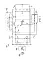
- FIG. 1illustrates a simplified schematic diagram of an embodiment of a power processing circuit including a controller constructed according to the principles of the invention
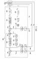
- FIG. 2illustrates a block diagram of an embodiment of a controller employable in a power processing circuit constructed according to the principles of the invention
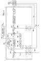
- FIGS. 3 and 4illustrate block diagrams of further embodiments of a controller employable in the power processing circuit constructed according to the principles of the invention
- FIG. 5illustrates numerically generated waveforms for rectified input voltage and inductor current for two cycles of the ac input voltage employed in a simulation in accordance with a power converter employing the controller of FIG. 2 ;
- FIG. 6illustrates a waveform of an input power estimate with respect to time in accordance with the controller of FIG. 2 ;
- FIG. 7illustrates a waveform of two cycles of an exemplary ac input voltage and a corresponding exemplary rectified ac input voltage produced in a simulation in accordance with a power converter employing the controller of FIG. 3 ;
- FIG. 8illustrates a waveform of a variation of percentage error of an estimated input power with respect to various input line conditions in a simulation in accordance with a power converter employing the controller of FIG. 3 ;
- FIG. 9illustrates waveforms of a percentage error of an estimated input power versus a measured input power obtained experimentally in accordance with a power converter employing the controller of FIG. 2 ;
- FIG. 10illustrates waveforms of a percentage error of an estimated input power versus a measured input power obtained experimentally in accordance with a power converter employing the controller of FIG. 3 ;
- FIG. 11illustrates a block diagram of an embodiment of a power system coupled to loads and including power converters controlled by a power system controller, constructed according to the principles of the invention.
- a power processing circuitis a power converter coupled to an ac power source including a controller configured to estimate an input power thereto.
- the need to estimate accurately an input power to a power converteris a parallel need to the general objective to reduce energy consumed by an electronic system, for example as described in the U.S. Patent Application Publication No. 2008/0130322 (Ser. No. 11/710,276) entitled “Power System with Power Converters Having an Adaptive Controller,” published Jun. 5, 2008 and U.S. Patent Application Publication No. 2008/0232141 (Ser. No. 12/051,334) entitled “Power System States,” published Sep. 25, 2008 (claiming priority to U.S. Patent Application Ser. No. 60/918,806), which are incorporated herein by reference.
- the integration of a product of instantaneous input voltage and current over a time interval from a time t 1 to t 2gives the total energy consumed in that time interval.
- the integration of the product of instantaneous voltage and current over one fundamental cycle of the ac input powergives the energy consumed in one cycle.
- dividing the above integral by the time periodgives power drawn by the power processing circuit.
- integration over one cycle divided by the time periodgives the average value of that function.
- the average value of a signalcan be obtained, or constructed, according to the principles of the invention by using a low-pass filter.
- Filtering the instantaneous product of a voltage and current with a low-pass filter such that the fundamental and harmonic frequency components thereof are substantially attenuatedgives the average power drawn by the power processing circuit. It can be noted that filtering an instantaneous product of voltage and current is a method of estimating power, which can be applied for any electrical system having input voltage and current that are periodic in nature.
- FIG. 1illustrated is a simplified schematic diagram of an embodiment of a power processing circuit (e.g., a power converter) 100 including a controller 102 constructed according to the principles of the invention.
- the power converterincludes a boost power stage 101 that may be configured to perform power factor correction, and a bypass path 103 comprising diode D 6 .
- An input power source 104 to the boost power stage 101is an ac power source, which is coupled to a diode bridge rectifier comprising diodes D 1 , D 2 , D 3 , and D 4 through EMI filter 106 .
- the boost power stage 101controlled by controller 102 , produces a regulated output voltage V out across an output filter capacitor C 1 , which provides the output voltage V out to a load, represented by resistor R 1 .
- the boost power stage 101includes a boost power switch Q boost and diode D 5 , which alternately conduct to transfer power from the input power source 104 through an inductor L 1 to the output filter capacitor C 1 .
- the controller 102senses the output voltage V out , the rectified input voltage V rect , and bridge rectified current i rect to produce a signal D to control a duty cycle of the boost power switch Q boost , thereby regulating the output voltage V out and the power factor of power drawn from the input power source 104 .
- bypass diode D 6would be reverse biased and hence the bypass current i bypass would be equal to zero and the bridge rectified current i rect would be equal to the inductor current i L .
- the power converter 100includes an electromagnetic interference (“EMI”) filter 106 to reduce high-frequency conducted noise fed back to the input power source 104 .
- EMIelectromagnetic interference
- the bypass path 103includes bypass diode D 6 which would peak charge the output voltage V out , in an unregulated fashion, when, for example, the control duty cycle D to the boost power switch Q boost is set to zero. In this condition, the inductor current i L would be equal to zero and the bridge rectified current i rect would be equal to the bypass current i bypass .
- FIG. 2illustrated is a block diagram of an embodiment of a controller 200 employable in a power processing circuit (e.g., a power converter) constructed according to the principles of the invention.
- the controlleris implemented with a digital controller.
- the controller 200is coupled to a boost power stage powered from an input power source, both of which were illustrated and described with reference to FIG. 1 .
- An output voltage V out from the boost power stageis fed back in signal processing path or outer voltage loop 240 with a sensing gain k dc to an analog to digital converter (designated “ADC”), producing feedback signal V out — fb (e.g., a scaled, digitized output voltage), which is subtracted from a reference output voltage V out — ref in summer 204 to produce a first error signal E 1 .
- the first error signal E 1is coupled to a voltage loop compensator 206 that produces a voltage compensation signal V c therefrom provided to a multiplier 208 .
- the voltage loop compensator 206may advantageously comprise a PI (“proportional-integral”) compensator cascaded with a high frequency pole.
- the rectified input voltage V rect to the boost power stageis sensed in a signal processing path or voltage feed-forward loop 244 with sensing gain k ac , converted to signal V in — sp in digital format (e.g., a scaled, digitized input voltage) by an ADC.
- This signalis coupled to a second input of the multiplier 208 .
- the signal V in — spis also coupled to an input of a feedforward circuit.
- the feedforward circuitfilters the scaled, digitized input voltage V in — sp in low-pass filter (“LPF”) 230 , squares the filtered scaled, digitized input voltage V in — sp in squarer 232 , the result of which is inverted in inverter 234 .
- LPFlow-pass filter
- the result of the feedforward circuitis illustrated in FIG. 2 as a voltage feed-forward signal V_ff, and is coupled to a third input of the multiplier 208 .
- An output signal from the multiplier 208is a time-dependent current reference signal I ref (t), which sets a desired current waveform for an inductor in the boost power stage.
- the controller 200senses a bridge rectified current i rect in a signal processing path or inner current loop 242 with sensing gain k c , which is coupled to an ADC, producing current feedback signal I_fdbk (e.g., a scaled, digitized bridge rectified current).
- I_fdbke.g., a scaled, digitized bridge rectified current.
- the current feedback signal I_fdbkis subtracted from the time-dependent current reference signal I ref (t) of the multiplier 208 in a summer 212 .
- the result of this subtraction(e.g., a second error signal E 2 ) is coupled to a current loop compensator 214 that produces a current compensation signal I c that is provided to a pulse-width modulator (“PWM”) 216 .
- PWMpulse-width modulator
- the pulse-width modulator 216produces a signal D to control duty cycle of a boost power switch in the boost power stage that was illustrated and described with reference to FIG. 1 .
- the current loop compensatormay advantageously comprise a PI compensator cascaded with a lead compensator.
- the bandwidth of the outer voltage loop 240is typically around five hertz (“Hz”), and the bandwidth of the inner current loop 242 is typically around five kilohertz (“kHz”). Other bandwidths may be used depending on system requirements.
- the voltage feed-forward loop 244is implemented to improve the line transient performance of a power converter.
- the sampling frequency of the scaled rectified input voltage V rectis chosen to be large enough (preferably 10 kHz or higher in many applications) to reconstruct the rectified input voltage V rect with little distortion.
- the sampling rate of the bridge rectified current i rectis done at least at the switching frequency of a boost power switch of the boost power stage, which typically is of the order of 100 kHz or higher in recent commercial product designs.
- the scaled, digitized input voltage signal V in — sp(indicative of the rectified input voltage V rect or the input voltage to the power converter) from the ADC and the current feedback signal I_fdbk (indicative of the bridge rectified current i rect ), are multiplied in a multiplier 252 (to produce a product of the input voltage and input current), for example at a 10 kHz rate, and are fed into a low-pass filter 254 .
- the low-pass filter 254may be implemented with a frequency response shaped so that the fundamental and higher harmonic frequencies of the rectified ac line voltage are substantially reduced. Low-pass filters with a desired frequency response can be readily implemented using design procedures well known in the art.
- a series of cascaded low-pass filterscan also be used as necessary to achieve an attenuation level for harmonic components. Since both an input voltage and an input current of a boost power stage are available in digital format at a high sampling rate, for instance, in the controller illustrated in FIG. 2 , the active power drawn by the boost power stage can be accurately estimated.
- a two-stage, cascaded, low-pass filteris implemented, without limitation, in a “C” computer language, each stage with a corner frequency at 12 Hz and with a computational repetition rate of 10 kHz.
- Ccomputer language
- the representation and implementation of a low-pass filter in a computer language such as Cis well known in the art, and will not be described here further in the interest of brevity.
- other filter structuressuch as cascaded band stop filters to remove the higher order harmonics, may be used.
- a filter output signal F srepresents a quantity that is a measure of the average input power to a boost power stage.
- man estimate of average input power, in watts for example, is thereby produced.
- due to non-idealities in sensing circuitsfor instance, when an additive but unknown bias current is present in a sense circuit or, as is typically the case, an operational amplifier exhibits a small but unknown offset voltage or a component deviates from a nominal value by tolerance, etc., or due to non-idealities in digital computation, for example, errors introduced due to truncation and round-off, deviations are unavoidably introduced between an actual and an estimated value of average input power.
- a linear or higher-order fitting equatione.g., a linear equation of the form m ⁇ x+c, where “m” and “c” are fitting constants and “x” is an independent variable, may be used for the conversion represented in a conversion circuit 258 .
- the parameters of the fitting equatione.g., m and c, can be determined for a given power converter during a calibration process by comparing estimated power with an actual average input power measurement, preferably in a controlled environment, using calibration processes well-known in the art. Fitting equations can also be used for variations with respect to input line voltage, an operating temperature, etc.
- the power estimatorworks well for both the conditions when the power processing is done by the boost power stage 101 regulating the output voltage V out , as well as when the boost power stage 101 is switched off, whereby the output voltage V out is peak charged in a unregulated fashion through the bypass path 103 .
- the bridge rectified current i rectwould be peaky in nature and since the controller 102 would have a lower computational load (as no processing is required to control the boost power stage 101 )
- the sampling and the computational rates to estimate the input powercan be increased to closely track the peak-natured current, and thereby accurately estimate the input power. Calibration may be done for this mode of operation to improve accuracy further.
- a process to estimate average input power for a power processing circuitthat may be coupled to an ac (or a dc) input power source has been introduced that processes a product of an input voltage times an input current to a power processing circuit with a filter (preferably a low-pass filter).
- the processavoids the need to form an integral of a product of an instantaneous input current and voltage over a cycle of an input voltage waveform, thereby avoiding the need for substantial computing resources to make an average input power estimate.
- the voltage compensation signal V c of the voltage loop compensator 306is proportional to the input power drawn by a boost power stage controlled with power-factor correction.
- the relationship between the input power drawn by the boost power stage and the output signal of the voltage loop compensator for input voltages having harmonic content up to, without limitation, the 11 th harmonic of the input ac voltage and total harmonic distortion less than, without limitation, ten percentis numerically established as described herein.
- FIG. 3illustrated is a block diagram of another embodiment of a controller 300 employable in the power processing circuit (e.g., a power converter) constructed according to the principles of the invention.
- the power processing circuite.g., a power converter
- a difference between the feedback circuit of the controllers described in FIG. 2 and FIG. 3is that the signal-processing order of a squaring function 332 and a low-pass filter 330 has been inverted before generating a voltage feed-forward signal V_ff.
- the average input power estimating process described previously hereinwould not be affected by this modification, but is preferable for the process as described below. Remaining elements in FIG. 3 and in following figures that are similar to similarly numbered elements in a previous figure and will not be described in the interest of brevity.
- a signal that is proportional to the mean-square value of the rectified input voltage V rectmay be provided by squaring the V in — sp signal (a scaled, digitized rectified input voltage) and coupling the squared result to a low-pass filter 330 with a corner frequency that substantially attenuates the fundamental of the line frequency and higher harmonic frequency components.
- the controller described in FIG. 3generates a voltage feed-forward signal V_ff that is inversely proportional to the mean-square value of the rectified input voltage V rect .
- the time-dependent current reference signal I ref (t) applied within the controlleri.e., the signal applied to the non-inverting input of an summer 312
- I ref ( t )V c ⁇ V rect ( t )/( V rms 2 ⁇ k ac ⁇ k adc ⁇ k lpf ), wherein k adc represent the signal processing gain of the ADC that provides the scaled, digitized input voltage signal.
- V in — sp , k lpfrepresents gain of the low-pass filter 330
- V rms 2represents the square of the RMS value of the rectified input voltage V rect .
- the voltage compensation signal V crepresents the output of the voltage loop compensator 306 .
- the average input power P dc to the boost power stagecan be obtained by integrating EQN 5 over one cycle of the ac input waveform to produce EQN 6:
- ⁇was numerically estimated to be quite close to unity, and the corresponding percentage error was estimated to be less than 0.15 percent for input voltage having harmonic content up to 11 th harmonic and total harmonic distortion less than 10 percent.
- the input powercan be accurately estimated using an ideal estimator where the voltage compensation signal V c is multiplied by a conversion factor, m, to get an estimate of average input power.
- a linear or higher-order fitting equationcan be used for the power estimator 350 , and the parameters therein can be calibrated.
- FIG. 4illustrated is a block diagram of a further embodiment of a controller 400 employable in a power processing circuit (e.g., a power converter) constructed according to the principles of the invention. Differences between the controllers described in FIGS. 3 and 4 are as follows: First, a reference rectified sine wave, V sine (t), of fixed amplitude, generated from a signal generator 410 that is phase-locked with the rectified input voltage signal V inst — sp using a phase-locked loop (“PLL”) 409 , is used as one of the inputs to the multiplier 408 , instead of the V inst — sp signal as illustrated in FIG. 3 .
- V sine (t)of fixed amplitude
- the inversion block 434does the inversion of the square-root of the signal fed from the LPF 430 instead of the simple inversion as illustrated in FIG. 3 .
- the voltage compensation signal V c of voltage loop compensator 406is a measure of the average input power to a boost power stage.
- mconversion factor
- a linear or higher order conversion unitcan be used, and the parameters of the same can be calibrated to improve the accuracy of power estimation.
- the first power estimation process introduced above with respect to FIG. 2 to estimate average input power, without limitation, for a boost power stage that may or may not be controlled with power-factor correction, using a low-pass filter to filter a product of instantaneous voltage and currentmay be numerically verified using a MathCadTM spreadsheet.
- Arbitrary voltage and current waveforms, each with fundamental frequencies of 100 Hz,may be numerically generated for 100 cycles of the ac input waveform.
- FIG. 5illustrated are numerically generated waveforms for rectified input voltage V rect and inductor current i L for two cycles of the ac input voltage employed in a simulation in accordance with a power converter employing the controller of FIG. 2 .
- Input poweris calculated by integrating the instantaneous product of input voltage and inductor current numerically over one ac input voltage waveform cycle.
- Input poweris also calculated numerically by filtering the product of the voltage and current samples for 100 ac input voltage waveform cycles using a two-stage, cascaded, low-pass filter, each with a corner frequency at 12 Hz.
- FIG. 6illustrates a waveform of an input power estimate P est with respect to time in accordance with the controller illustrated and described with respect to FIG. 2 .
- the steady state value of the filtered outputmay be compared with the numerical integration method and found that the percentage error is insignificant.
- the value of the parameter ⁇ and the percentage error introduced due to assuming its value is unitymay be estimated using MathCadTM for different ac line harmonic conditions.
- the ac input voltage waveform in the time domain with a selected amount of harmonic contentis numerically generated.
- the rectified input ac line voltageis generated by taking the absolute value of the ac input voltage waveform.
- FIG. 7illustrates a waveform of two cycles of an exemplary ac input voltage 701 and a corresponding exemplary rectified ac input voltage 702 (which coincides with the ac input voltage for portions of a cycle and thus hides portions thereof) produced in a simulation in accordance with a power converter employing the controller of FIG. 3 .
- the waveform of FIG. 7provides the fundamental component of the ac input voltage equal to 100 volts (“V”) and the amplitude of the third harmonic equal to 10 V, with no phase shift relative to the fundamental component.
- Vvolts
- the inner current loop 342 illustrated in FIG. 3may be modeled in MathCadTM as a first-order system with a corner frequency at two kHz.
- the function G(V rect (s))may be obtained by calculating the response of the inner current loop 342 loop to the Fast Fourier Transform (“FFT”) of the rectified input voltage V rect (s), where the symbol “s” represents the complex argument of the respective transformed function in the frequency domain.
- the function G(V rect (t))is obtained by taking the inverse FFT of G(V rect (s)). Then the value of ⁇ was calculated by integrating EQN 7 numerically, and the corresponding percent error “%_error” is calculated using EQN 9.
- FIG. 8illustrated is a plot of a variation of percentage error (“error (%)”) of an estimated input power in accordance with a power converter employing the controller of FIG. 3 .
- errorpercentage error
- the percentage error of the estimated input poweris provided with respect to the input ac line condition. It is evident in FIG. 8 that the percentage error introduced due to assuming a unity value for the factor ⁇ may be considered insignificant.
- An experimental setupmay be constructed using a 650-watt power converter to validate the input power estimation processes introduced herein.
- the power converterincluded a power-factor corrected, single-phase, boost power stage drawing power from an ac line.
- the output of the boost power stagewas converted to 12 V by an isolated, dc-dc power converter.
- the controller for the boost power stagemay be realized using a digital controller, similar to one illustrated and described previously hereinabove.
- a microcontrollermay be used on the secondary side of the power converter to provide an interface with an external system (such as a server or storage processor) for supervisory activities.
- a universal asynchronous receiver transmitter (“UART”) communication link(or any other suitable communication link) may be provided between the digital controller on the primary side of the isolation boundary of the dc-to-dc section and the microcontroller on the secondary side of the isolation boundary.
- the estimated power calculated by the digital controllermay be monitored by an external system via the above-mentioned communication link.
- the communication update rate through the UART communication linkmay be about every ten milliseconds (“ms”), depending on the requirements of the external system. Voltages and currents in the aforementioned setup are measured using typical laboratory procedures.
- the fitting parameters m and c used to calculate the estimated input powermay be calibrated at 20 amperes (“A”) and 40 A of load current, at an ac input voltage of 110 V with zero total harmonic distortion (“THD”), and with a line frequency of 60 Hz, for example,
- the ATEmay then communicate appropriate calibration parameters for m and c to the controller, allowing the controller to use the stored calibration parameters to improve the accuracy of an estimated input power.
- the calibration processmay be carried out for multiple operating points to improve overall accuracy, for example, at multiple ac input line frequencies, multiple line voltages, multiple harmonic distortion contents, and multiple output power levels.
- the input voltagemay be set at three different line conditions.
- the firstis a substantially pure sine wave of 110 V.
- the secondis a fundamental component of 110 V plus a third harmonic of 11 V at zero degrees relative to the fundamental.
- the thirdis a fundamental component of 110 V plus a ninth harmonic of 11 V at zero degrees relative to the fundamental.
- FIG. 9illustrated are plots of a percentage error of an estimated input power versus a measured input power in accordance with a power converter employing the controller of FIG. 2 . More specifically, the illustrated plots provide the percentage error for the input power estimate for a process in which a low-pass filter filters a product of an input voltage times an input current to the power converter.
- FIG. 10illustrated are plots of a percentage error of an estimated input power versus a measured input power in accordance with a power converter employing the controller of FIG. 3 . More specifically, the illustrated plots provide the percentage error for the input power estimate for a process in which a voltage compensation signal of a voltage loop compensator is scaled by gains and processed by an input power estimator. It is evident from the plots of FIGS. 9 and 10 that errors in the input power estimate are well within a +/ ⁇ 2% error band for a wide range of load and input voltage harmonic conditions.
- the input active power drawn by a power convertercan be accurately estimated, for example, with accuracy better than +/ ⁇ 2%, with a process that advantageously employs a modest expenditure of signal-processing resources.
- the input power in accordance with a power convertercan be estimated by filtering the integrated value of a product of instantaneous voltage and current with a low-pass filter.
- the input power in a power convertercan be estimated by scaling a voltage compensation signal of a voltage loop compensator processed by an input power estimator.
- FIG. 11illustrated is a block diagram of an embodiment of a power system, 1100 , coupled to loads, including power converters controlled by a power system controller (designated “PSC”), constructed according to the principles of the invention.
- the power systemis operable in a plurality of operational states, each with an associated power level. A requirement occurring with increasing frequency for systems of recent design is to measure and report the power drawn by system elements in their various operational states so that the total energy consumed by the system can be minimized, for example, by the power system controller.
- the loads in FIG. 11are represented, without limitation, by a plurality of servers (designated “SVR_ 1 . . . SVR_n” and also referred to as “SVR”) powered by respective power converters (designated “PU_ 1 . . . PU_n” and also referred to as “PU”) over respective power buses (designated “PB_ 1 . . . PB_n” and also referred to as “PB”).
- Each server SVRmay be individually coupled over respective server buses (designated “SVRBUS_ 1 . . .
- SVRBUS_nand also referred to as “SVRBUS”) to a respective power converter PU for its power source as illustrated herein, or may be coupled to more than one power converter PU and powered in a redundant manner to form multiple redundant power converters PU.
- the power system controllermay also be powered by one of the illustrated power converters PU, or by another power converter not shown.
- the power converters PUare coupled to the power system controller PSC over respective power converter communication buses (designated “PCBUS_ 1 . . . PCBUS_n” and also referred to as “PCBUS”) that conduct signals therebetween to communicate requests for a power converter operational state PC op — state from the power system controller PSC to a power converter PU.
- the power system controller PSCmay also be coupled over a bus (designated “BUS_env”) to a circuit element (not shown) signaling an environmental parameter such as a component temperature.
- the power system controller PSCmay be coupled over a bus (designated “BUS_test”) to a signal source such as a manufacturing test set that provides a power converter parameter measured after a manufacturing step.
- the power system controller PSCreceives signals representing a power converter status PC status from the power converters PU over the respective power converter communication buses PCBUS and transmits commands thereover for the power converter operational states PC op — state to the power converters PU.
- a signal transmitted by a power convertermay include an estimate of its input power, which is communicated to the power system controller over its respective power converter communication bus.
- the commands for the power converter PU to enter the power converter operational states PC op — statewhich may advantageously include consideration of the estimate of power converter input power, can be used to enhance (e.g., optimize) an operational efficiency or reliability of the power converter PU at a power system level.
- the ability of a power converter to estimate accurately its input poweris thus essential to minimizing the energy consumed by the system.
- the controllerincludes a multiplier configured to produce a product of an input current and an input voltage of the power processing circuit.
- the controlleralso includes a low-pass filter configured to produce an input power estimate of an input power to the power processing circuit as a function of the product of the input current and the input voltage.
- the input power estimateis an output signal of the controller.
- the controllermodifies the input power estimate with a linear correction in a conversion circuit to produce a signal substantially proportional to the input power of the power processing circuit.
- the multiplier and low-pass filterinclude a digital circuit. The controller can also control a power factor of the power processing circuit.
- the controllerincludes a voltage loop compensator configured to produce a voltage compensation signal as a function of an output voltage of the power processing circuit.
- the controlleralso includes an input power estimator configured to produce an input power estimate of an input power to the power processing circuit as a function of the voltage compensation signal.
- the input power estimateis an output signal of the controller.
- the controllerfurther includes a feedforward circuit that produces a signal inversely proportional to a filtered square of an input voltage to the power processing circuit, and a multiplier coupled to an output of the voltage loop compensator and to the feedforward circuit.
- the controllerfurther includes a summer that forms a difference between an output of the multiplier and a signal representing a current in an inductor of a boost power stage of the power processing circuit, and a current loop compensator coupled to the summer.
- An output of the current loop compensatoris coupled to a pulse-width modulator, and an output of the pulse-width modulator is coupled to a power switch of the boost power stage.
- the input power estimatoris coupled to an output of the voltage loop compensator, and employs a relationship that may be a linear relationship in a conversion circuit to produce the input power estimate.
- the filtered square of an input voltage to the power processing circuitis filtered to attenuate substantially a fundamental and its higher harmonic frequency components of an ac input line powering the power processing circuit.
- the input power estimatorincludes a digital circuit.
- the methodfurther includes forming a difference between the product and a current signal representing a current in an inductor of the power processing circuit, coupling a current loop compensator to the summer, generating a pulse-width modulated signal from an output of the current loop compensator, and controlling a power switch of the power processing circuit with the pulse-width modulated signal.
- the methodfurther includes using a linear relationship in a conversion circuit to produce the signal indicative of input power from the output of the voltage loop compensator.
- the methodfurther includes filtering the square of the input voltage to the power processing circuit with a filter that substantially attenuates a fundamental and its higher harmonic frequency components of an ac input line powering the power processing circuit.
- the methodincludes using a digital circuit to produce the input power estimate.
- the methodincludes producing an output signal of the controller from the input power estimate.
- the input power estimatemay be performed with the boost power factor correction (“PFC”) circuit inactive, or with the PFC circuit configured to provide a power factor between about 0.5 and 0.95.
- the input power estimatemay be performed using a substantially dc input power source, with or without the boost circuit active.
- the controllermay be calibrated to improve the accuracy of the input power estimate.
- the calibration parametersmay be determined at a manufacturing test process using an ATE, with the calibration parameters stored in a nonvolatile memory for use by the controller during the input power estimate process.
- the controllerincluding the power estimator, is part of a power converter system, redundant or non-redundant, providing electrical power to a system external to the power converter.
- the external systemmay comprise a data processing system such as a server, a storage system, a data packet router, or any system requiring electrical power where an accurate input power estimate would be advantageous.
- the controlleris configured to provide the input power estimate to the external system through a communications means, including but not limited to I 2 C, Ethernet, a SPI bus, or any suitable electronic communications medium.
- the external systemmay command the controller to provide the input power estimate, or conversely, the controller may provide the input power estimate to the external system as part of a scheduled information transfer.
- Another exemplary embodiment of the inventionprovides a method of producing an input power estimate of a power processing circuit.
- the methodincludes multiplying a current and a voltage to produce a current-voltage product, and filtering the current-voltage product with a low-pass filter to produce the input power estimate.
- the methodfurther includes modifying the input power estimate with a linear correction in a conversion circuit to produce a signal substantially proportional to a power level.
- the methodincludes performing the multiplication and the filtering with a digital circuit.
- the methodincludes producing an output signal of the controller from the input power estimate.
Landscapes
- Engineering & Computer Science (AREA)
- Power Engineering (AREA)
- Dc-Dc Converters (AREA)
- Rectifiers (AREA)
Abstract
Description
Iref(t)=Vc·Vrect(t)/(Vrms2·kac·kadc·klpf),
wherein kadcrepresent the signal processing gain of the ADC that provides the scaled, digitized input voltage signal. Vin
iL(t)=G(Vc·Vrect(t)/(Vrms2·kac·kadc·klpf)),
wherein the function G( ) represents the response of the inner
iL(t)=[Vc/(Vrms2·kac·kadc·klpf)]·G((Vrect(t).
Pin(t)=Vrect(t)·iL(t).
Substituting
Pin(t)=[Vc/(Vrms2·kac·kadc·klpf)]·G(Vrect(t))·Vrect(t).
wherein as set forth in EQN 7:
Pest=Vc/(kac·kadc·klpf).
Thus, from EQN 8 it can be seen that the voltage compensation signal Vcis a measure of the average input power to a boost power stage. In an ideal case when the voltage compensation signal Vcis multiplied by a conversion factor, m, an estimate of average input power, in watts for example, is thereby produced with a percentage error between the actual and the estimate given by the
| TABLE I | |||
| Cond. | Harmonic Value (in Vrms) @ angle (deg.) | Vthd | Error |
| No. | 1st | 3rd | 5th | 7th | 9th | 11th | (%) | (%) |
| 1 | 100 | 0 | 0 | 0 | 0 | 0 | 0 | −0.085 |
| 2 | 100 | 10 @ 0 | 0 | 0 | 0 | 0 | 10 | −0.089 |
| 3 | 100 | 10 @ 45 | 0 | 0 | 0 | 0 | 10 | −0.089 |
| 4 | 100 | 10 @ 90 | 0 | 0 | 0 | 0 | 10 | −0.09 |
| 5 | 100 | 10 @ 135 | 0 | 0 | 0 | 0 | 10 | −0.09 |
| 6 | 100 | 10 @ 180 | 0 | 0 | 0 | 0 | 10 | −0.091 |
| 7 | 100 | 10 @ 270 | 0 | 0 | 0 | 0 | 10 | −0.09 |
| 8 | 100 | 10 @ 315 | 0 | 0 | 0 | 0 | 10 | −0.089 |
| 9 | 100 | 0 | 10 @ 45 | 0 | 0 | 0 | 10 | −0.098 |
| 10 | 100 | 0 | 0 | 10 @ 270 | 0 | 0 | 10 | −0.112 |
| 11 | 100 | 0 | 0 | 0 | 10 @ 90 | 0 | 10 | −0.129 |
| 12 | 100 | 0 | 0 | 0 | 0 | 10 @ 315 | 10 | −0.149 |
| 13 | 100 | 5 @ 0 | 5 @ 0 | 5 @ 0 | 5 @ 0 | 0 | 10 | −0.102 |
| 14 | 100 | 0 | 5 @ 0 | 5 @ 0 | 5 @ 0 | 5 @ 0 | 10 | −0.114 |
| 15 | 100 | 8 @ 0 | 7 @ 180 | 0 | 0 | 0 | 10 | −0.096 |
Claims (20)
Priority Applications (1)
| Application Number | Priority Date | Filing Date | Title |
|---|---|---|---|
| US11/955,642US7906941B2 (en) | 2007-06-19 | 2007-12-13 | System and method for estimating input power for a power processing circuit |
Applications Claiming Priority (2)
| Application Number | Priority Date | Filing Date | Title |
|---|---|---|---|
| US94502407P | 2007-06-19 | 2007-06-19 | |
| US11/955,642US7906941B2 (en) | 2007-06-19 | 2007-12-13 | System and method for estimating input power for a power processing circuit |
Publications (2)
| Publication Number | Publication Date |
|---|---|
| US20080315852A1 US20080315852A1 (en) | 2008-12-25 |
| US7906941B2true US7906941B2 (en) | 2011-03-15 |
Family
ID=40135820
Family Applications (2)
| Application Number | Title | Priority Date | Filing Date |
|---|---|---|---|
| US11/955,627AbandonedUS20080316779A1 (en) | 2007-06-19 | 2007-12-13 | System and method for estimating input power for a power processing circuit |
| US11/955,642Active2028-09-15US7906941B2 (en) | 2007-06-19 | 2007-12-13 | System and method for estimating input power for a power processing circuit |
Family Applications Before (1)
| Application Number | Title | Priority Date | Filing Date |
|---|---|---|---|
| US11/955,627AbandonedUS20080316779A1 (en) | 2007-06-19 | 2007-12-13 | System and method for estimating input power for a power processing circuit |
Country Status (1)
| Country | Link |
|---|---|
| US (2) | US20080316779A1 (en) |
Cited By (36)
| Publication number | Priority date | Publication date | Assignee | Title |
|---|---|---|---|---|
| US20080054874A1 (en)* | 2006-08-31 | 2008-03-06 | Sriram Chandrasekaran | Power Converter Employing Regulators with a Coupled Inductor |
| US20090097290A1 (en)* | 2007-03-14 | 2009-04-16 | Sriram Chandrasekaran | Isolated Power Converter |
| US20100020579A1 (en)* | 2008-07-25 | 2010-01-28 | Melanson John L | Power Supply With Accurate Energy Measurement |
| US20100149838A1 (en)* | 2006-12-01 | 2010-06-17 | Artusi Daniel A | Power System with Power Converters Having an Adaptive Controller |
| US20100321958A1 (en)* | 2009-06-17 | 2010-12-23 | Antony Brinlee | Power Converter Employing a Variable Switching Frequency and a Magnetic Device with a Non-Uniform Gap |
| US20110110126A1 (en)* | 2009-11-10 | 2011-05-12 | Power Integrations, Inc. | Controller compensation for frequency jitter |
| US20110216565A1 (en)* | 2008-11-11 | 2011-09-08 | Gree Electric Appliances Inc. Of Zhuhai | One-cycle controlled power factor correction method |
| US20110292699A1 (en)* | 2010-05-26 | 2011-12-01 | Texas Instruments Incorporated | Systems and Methods for Distortion Reduction |
| US20130182781A1 (en)* | 2010-10-20 | 2013-07-18 | Megachips Corporation | Plc/power-supply hybrid device and device with communication function |
| US8520414B2 (en) | 2009-01-19 | 2013-08-27 | Power Systems Technologies, Ltd. | Controller for a power converter |
| US8638578B2 (en) | 2009-08-14 | 2014-01-28 | Power System Technologies, Ltd. | Power converter including a charge pump employable in a power adapter |
| US8643222B2 (en) | 2009-06-17 | 2014-02-04 | Power Systems Technologies Ltd | Power adapter employing a power reducer |
| US20140159693A1 (en)* | 2012-12-10 | 2014-06-12 | Chengdu Monolithic Power Systems Co., Ltd. | Step-down switching mode power supply and the method thereof |
| US8767418B2 (en) | 2010-03-17 | 2014-07-01 | Power Systems Technologies Ltd. | Control system for a power converter and method of operating the same |
| US8787043B2 (en) | 2010-01-22 | 2014-07-22 | Power Systems Technologies, Ltd. | Controller for a power converter and method of operating the same |
| US8792256B2 (en) | 2012-01-27 | 2014-07-29 | Power Systems Technologies Ltd. | Controller for a switch and method of operating the same |
| US8792257B2 (en) | 2011-03-25 | 2014-07-29 | Power Systems Technologies, Ltd. | Power converter with reduced power dissipation |
| US20150061522A1 (en)* | 2013-08-27 | 2015-03-05 | Texas Instruments Incorporated | Method and apparatus for calculating an average value of an inaccessible current from an acessible current |
| US8976549B2 (en) | 2009-12-03 | 2015-03-10 | Power Systems Technologies, Ltd. | Startup circuit including first and second Schmitt triggers and power converter employing the same |
| US9019061B2 (en) | 2009-03-31 | 2015-04-28 | Power Systems Technologies, Ltd. | Magnetic device formed with U-shaped core pieces and power converter employing the same |
| US9077248B2 (en) | 2009-06-17 | 2015-07-07 | Power Systems Technologies Ltd | Start-up circuit for a power adapter |
| US9088216B2 (en) | 2009-01-19 | 2015-07-21 | Power Systems Technologies, Ltd. | Controller for a synchronous rectifier switch |
| US9099232B2 (en) | 2012-07-16 | 2015-08-04 | Power Systems Technologies Ltd. | Magnetic device and power converter employing the same |
| US9106130B2 (en) | 2012-07-16 | 2015-08-11 | Power Systems Technologies, Inc. | Magnetic device and power converter employing the same |
| US20150286230A1 (en)* | 2014-04-03 | 2015-10-08 | Supertex, Inc. | Current Control Circuit for Linear LED Driver |
| US9190898B2 (en) | 2012-07-06 | 2015-11-17 | Power Systems Technologies, Ltd | Controller for a power converter and method of operating the same |
| US9197132B2 (en) | 2006-12-01 | 2015-11-24 | Flextronics International Usa, Inc. | Power converter with an adaptive controller and method of operating the same |
| US9214264B2 (en) | 2012-07-16 | 2015-12-15 | Power Systems Technologies, Ltd. | Magnetic device and power converter employing the same |
| US9240712B2 (en) | 2012-12-13 | 2016-01-19 | Power Systems Technologies Ltd. | Controller including a common current-sense device for power switches of a power converter |
| US9246391B2 (en) | 2010-01-22 | 2016-01-26 | Power Systems Technologies Ltd. | Controller for providing a corrected signal to a sensed peak current through a circuit element of a power converter |
| US9300206B2 (en) | 2013-11-15 | 2016-03-29 | Power Systems Technologies Ltd. | Method for estimating power of a power converter |
| US9379629B2 (en) | 2012-07-16 | 2016-06-28 | Power Systems Technologies, Ltd. | Magnetic device and power converter employing the same |
| US9621018B2 (en) | 2010-12-20 | 2017-04-11 | Texas Instruments Incorporated | Systems for indirect average current measurement |
| US9948173B1 (en)* | 2014-11-18 | 2018-04-17 | The Board Of Trustees Of The University Of Alabama | Systems and methods for short-time fourier transform spectrogram based and sinusoidality based control |
| US11057981B2 (en)* | 2019-08-15 | 2021-07-06 | Energy Focus, Inc. | System and method for providing high power factor wired lamp control |
| US11395396B2 (en) | 2019-08-15 | 2022-07-19 | Energy Focus, Inc. | System and method for providing high power factor wired lamp control |
Families Citing this family (65)
| Publication number | Priority date | Publication date | Assignee | Title |
|---|---|---|---|---|
| US7280026B2 (en) | 2002-04-18 | 2007-10-09 | Coldwatt, Inc. | Extended E matrix integrated magnetics (MIM) core |
| US7417875B2 (en)* | 2005-02-08 | 2008-08-26 | Coldwatt, Inc. | Power converter employing integrated magnetics with a current multiplier rectifier and method of operating the same |
| US7876191B2 (en) | 2005-02-23 | 2011-01-25 | Flextronics International Usa, Inc. | Power converter employing a tapped inductor and integrated magnetics and method of operating the same |
| US7675758B2 (en) | 2006-12-01 | 2010-03-09 | Flextronics International Usa, Inc. | Power converter with an adaptive controller and method of operating the same |
| US7889517B2 (en) | 2006-12-01 | 2011-02-15 | Flextronics International Usa, Inc. | Power system with power converters having an adaptive controller |
| US7667986B2 (en) | 2006-12-01 | 2010-02-23 | Flextronics International Usa, Inc. | Power system with power converters having an adaptive controller |
| US20080316779A1 (en)* | 2007-06-19 | 2008-12-25 | Chandrasekaran Jayaraman | System and method for estimating input power for a power processing circuit |
| JP2009131066A (en)* | 2007-11-26 | 2009-06-11 | Fujitsu Ltd | Power supply circuit and electronic equipment |
| TWI368837B (en)* | 2008-07-16 | 2012-07-21 | Acbel Polytech Inc | Ac to dc power converter with hold up time function |
| US20100080026A1 (en)* | 2008-10-01 | 2010-04-01 | Xiaoyang Zhang | Power factor correction circuit |
| US8143871B1 (en)* | 2008-11-20 | 2012-03-27 | Linear Technology Corporation | Dynamically-compensated controller |
| US8258768B2 (en)* | 2008-12-12 | 2012-09-04 | Schneider Electric USA, Inc. | Low EMI producing switch-mode power supply within an intelligent electronic device |
| US9401635B2 (en)* | 2009-04-27 | 2016-07-26 | Hewlett Packard Enterprise Development Lp | Switching power supply for a load in stanby mode |
| TWI390213B (en)* | 2009-05-13 | 2013-03-21 | Silicon Motion Inc | Dc voltage measuring apparatus and method for dc voltage measurement |
| US8098506B2 (en)* | 2009-06-02 | 2012-01-17 | Power Integrations, Inc. | Single-stage power supply with power factor correction and constant current output |
| US8520420B2 (en) | 2009-12-18 | 2013-08-27 | Power Systems Technologies, Ltd. | Controller for modifying dead time between switches in a power converter |
| WO2011083576A1 (en)* | 2010-01-07 | 2011-07-14 | 三菱電機株式会社 | Current detection device for inductive load |
| US8972216B2 (en) | 2010-03-09 | 2015-03-03 | Infineon Technologies Austria Ag | Methods and apparatus for calibration of power converters |
| US20110273142A1 (en)* | 2010-05-07 | 2011-11-10 | Norman Luwei Jin | Parallel Boost Unity Power Factor High Power Battery Charger |
| JP2012016172A (en)* | 2010-06-30 | 2012-01-19 | Toshiba Corp | Power supply circuit and power supply control method |
| US9088224B2 (en)* | 2010-07-21 | 2015-07-21 | Lihua Chen | Variable voltage converter with stabilized output voltage |
| US20120106211A1 (en)* | 2010-11-03 | 2012-05-03 | Texas Instruments Incorporated | Power factor and line distortion method and apparatus |
| US8829879B2 (en)* | 2010-12-03 | 2014-09-09 | Maxim Integrated Products, Inc. | Inductor current measurement for DC to DC converters |
| JP5355617B2 (en)* | 2011-04-25 | 2013-11-27 | 三菱電機株式会社 | Power supply |
| TWI439023B (en)* | 2011-07-13 | 2014-05-21 | Wistron Corp | Low noise buck conversion circuit and low noise voltage supply assembly |
| US8773101B2 (en)* | 2011-08-04 | 2014-07-08 | Hamilton Sundstrand Corporation | Power management for loads supplied with power from wild sources |
| TWI484739B (en)* | 2011-11-11 | 2015-05-11 | Richtek Technology Corp | Active power factor correction circuit and related pfc controller |
| US9548650B1 (en) | 2011-11-22 | 2017-01-17 | Google Inc. | AC power monitoring and parameter determination |
| US9496782B2 (en)* | 2011-12-22 | 2016-11-15 | B/E Aerospace, Inc. | Digitally-controlled power factor correction circuits, methods and articles of manufacture |
| WO2013115784A1 (en)* | 2012-01-31 | 2013-08-08 | Hewlett-Packard Development Company, L.P. | Reducing current harmonics at light loads |
| KR101288615B1 (en)* | 2012-03-28 | 2013-07-22 | 주식회사 만도 | Control circuit for discontinuous conduction mode power factor correction converter using harmonic modulation |
| CN103516191B (en)* | 2012-06-29 | 2015-11-04 | 珠海格力电器股份有限公司 | Power factor correction method, circuit and switching power supply |
| TWI473405B (en)* | 2012-09-20 | 2015-02-11 | Univ Nat Cheng Kung | Power conversion apparatus and control method thereof |
| JP6045308B2 (en)* | 2012-11-08 | 2016-12-14 | 三菱重工業株式会社 | Active converter control device, method and program thereof |
| US9335780B1 (en)* | 2013-01-07 | 2016-05-10 | Lockheed Martin Corporation | Input range expander for power supplies |
| US10890961B2 (en) | 2013-06-28 | 2021-01-12 | Microchip Technology Incorporate | Method, power monitor microcontroller, and apparatus of non-linear compensation and monitoring of power for power supply units |
| JP6213183B2 (en) | 2013-11-21 | 2017-10-18 | 富士電機株式会社 | Switching power supply circuit |
| US9559615B2 (en)* | 2014-06-02 | 2017-01-31 | Magtech Industries Corporation | Fully variable power supply controller |
| WO2016051917A1 (en)* | 2014-09-29 | 2016-04-07 | シャープ株式会社 | Power supply device and lighting apparatus equipped with same |
| US10231306B2 (en)* | 2014-10-14 | 2019-03-12 | Philips Lighting Holding B.V. | Lighting controller, a lighting system and a method for controlling lighting |
| US9595872B2 (en)* | 2014-10-22 | 2017-03-14 | Bose Corporation | Adjustment of circuit operations in response to AC line distortion |
| US9729055B1 (en)* | 2014-10-23 | 2017-08-08 | General Electric Company | Systems and methods of increasing power converter efficiency |
| US9632120B2 (en)* | 2014-12-24 | 2017-04-25 | Infineon Technologies Austria Ag | System and method for measuring power in a power factor converter |
| US9966841B2 (en)* | 2015-05-18 | 2018-05-08 | Texas Instruments Incorporated | Power factor correction |
| JP6288534B2 (en)* | 2015-06-11 | 2018-03-07 | 富士電機株式会社 | Power converter |
| US10069426B2 (en)* | 2016-03-12 | 2018-09-04 | Semiconductor Components Industries, Llc | Active clamp flyback converter |
| US10003259B2 (en)* | 2016-04-09 | 2018-06-19 | Skyworks Solutions, Inc. | Voltage converter and control method thereof |
| EP3258584A1 (en)* | 2016-06-17 | 2017-12-20 | Continental Automotive GmbH | Voltage converter and method for converting a voltage |
| US10740740B1 (en) | 2016-06-29 | 2020-08-11 | Square, Inc. | Monitoring and recovery for a USB interface |
| US9710037B1 (en)* | 2016-06-29 | 2017-07-18 | Square, Inc. | USB voltage regulation and switching |
| US10409755B2 (en)* | 2016-06-29 | 2019-09-10 | Square, Inc. | Multi-mode USB interface |
| US9979281B2 (en)* | 2016-10-07 | 2018-05-22 | Excelitas Technologies Corp. | Apparatus and method for dynamic adjustment of the bandwidth of a power converter |
| WO2019060392A1 (en)* | 2017-09-22 | 2019-03-28 | Huawei Technologies Co., Ltd. | Hybrid boost converters |
| TWI685183B (en)* | 2018-07-04 | 2020-02-11 | 群光電能科技股份有限公司 | Hybrid-mode boost power factor corrector |
| KR102609536B1 (en)* | 2018-07-13 | 2023-12-05 | 삼성전자주식회사 | Electronic apparatus |
| CA3050881A1 (en)* | 2018-08-01 | 2020-02-01 | Osram Sylvania Inc. | Methods of calculating power input and electrical power systems utilizing same |
| US10803909B2 (en) | 2018-08-24 | 2020-10-13 | Micron Technology, Inc. | Power management component for memory sub system power cycling |
| US10547237B1 (en)* | 2019-01-30 | 2020-01-28 | Mks Instruments, Inc. | Power converter control apparatus and method for high stability and power factor improvement in the presence of high source impedances |
| US10897201B2 (en)* | 2019-05-09 | 2021-01-19 | Nxp B.V. | Switched mode power supply signal reconstruction |
| CN112234815B (en)* | 2020-09-29 | 2022-05-13 | 浪潮电子信息产业股份有限公司 | Feedback voltage slope compensation method and related device |
| IT202100007628A1 (en) | 2021-03-29 | 2022-09-29 | St Microelectronics Srl | CONTROL CIRCUIT, CORRESPONDING ELECTRONIC CONVERTER DEVICE AND RELATED OPERATING METHOD |
| CN113589033B (en) | 2021-07-29 | 2024-08-13 | 昂宝电子(上海)有限公司 | Power signal detection circuit and method |
| CN114692482A (en)* | 2021-09-26 | 2022-07-01 | 浙江华云信息科技有限公司 | An evaluation device and method for evaluating the content of current harmonics fed into a power grid in a charging station |
| WO2023088568A1 (en)* | 2021-11-22 | 2023-05-25 | Huawei Technologies Co., Ltd. | Controller for controlling a balancer circuit |
| CN116430111A (en)* | 2021-12-30 | 2023-07-14 | 台达电子工业股份有限公司 | Power detection circuit and control circuit |
Citations (205)
| Publication number | Priority date | Publication date | Assignee | Title |
|---|---|---|---|---|
| US1376978A (en) | 1917-11-24 | 1921-05-03 | Cutler Hammer Mfg Co | Regulator for alternating currents |
| US3346798A (en) | 1963-08-08 | 1967-10-10 | Gen Electric | Regulator for inverter |
| US3358210A (en) | 1964-06-25 | 1967-12-12 | Gen Electric | Voltage regulator |
| US3433998A (en) | 1965-04-24 | 1969-03-18 | Philips Corp | Circuit arrangement for frame correction |
| US3484562A (en) | 1966-09-21 | 1969-12-16 | Nortronics Co | Magnetic transducer with clamped body sections to hold core pieces |
| US3553620A (en) | 1967-09-14 | 1971-01-05 | Ibm | Combined transformer and indicator device |
| US3622868A (en) | 1970-02-06 | 1971-11-23 | Joachim H Todt | Regulating power transformer with magnetic shunt |
| US3681679A (en) | 1971-05-07 | 1972-08-01 | Kheemoy Chung | Constant voltage transformer three-phase ferro resonant |
| US3708744A (en) | 1971-08-18 | 1973-01-02 | Westinghouse Electric Corp | Regulating and filtering transformer |
| US4019122A (en) | 1974-08-14 | 1977-04-19 | Telcon-Magnetic Cores Limited | Stabilized power supplies |
| US4075547A (en) | 1975-07-23 | 1978-02-21 | Frequency Technology, Inc. | Voltage regulating transformer |
| US4327348A (en) | 1977-05-20 | 1982-04-27 | Tdk Electronics Co., Ltd. | Variable leakage transformer |
| US4471423A (en) | 1982-02-17 | 1984-09-11 | Hase A M | Multi-voltage DC output with single reactor voltage control |
| US4499481A (en) | 1983-09-14 | 1985-02-12 | The United States Of America As Represented By The Secretary Of The Navy | Heterojunction Schottky gate MESFET with lower channel ridge barrier |
| US4570174A (en) | 1981-08-21 | 1986-02-11 | The United States Of America As Represented By The Secretary Of The Army | Vertical MESFET with air spaced gate electrode |
| US4577268A (en) | 1982-12-20 | 1986-03-18 | Rca Corporation | Switching dc-to-dc converters |
| US4581691A (en) | 1984-04-23 | 1986-04-08 | At&T Bell Laboratories | Balanced constant current sensing circuit inherently immune to longitudinal currents |
| US4636823A (en) | 1984-06-05 | 1987-01-13 | California Institute Of Technology | Vertical Schottky barrier gate field-effect transistor in GaAs/GaAlAs |
| US4660136A (en) | 1985-01-24 | 1987-04-21 | Honeywell Inc. | Single regulation power supply with load compensation of an auxiliary voltage output |
| US4770667A (en) | 1982-12-07 | 1988-09-13 | Board Of Regents, U T Systems | Use of substituted 2-(2'-hydroxyaryl)-2H-benzotriazolesulfonates as photostabilizing agents for natural and synthetic fibres |
| US4770668A (en) | 1988-01-19 | 1988-09-13 | National Starch And Chemical Corporation | Ethylene urea compositions useful as permanent press promoting chemicals |
| US4785387A (en) | 1986-04-28 | 1988-11-15 | Virginia Tech Intellectual Properties, Inc. | Resonant converters with secondary-side resonance |
| US4803609A (en) | 1985-10-31 | 1989-02-07 | International Business Machines Corporation | D. C. to D. C. converter |
| US4823249A (en) | 1987-04-27 | 1989-04-18 | American Telephone And Telegraph Company At&T Bell Laboratories | High-frequency resonant power converter |
| US4866367A (en) | 1988-04-11 | 1989-09-12 | Virginia Tech Intellectual Properties, Inc. | Multi-loop control for quasi-resonant converters |
| US4887061A (en) | 1988-01-18 | 1989-12-12 | Tdk Corporation | Transformer for a flyback type converter |
| US4899271A (en) | 1987-07-22 | 1990-02-06 | Scanpower | Power supply circuit |
| US4903089A (en) | 1988-02-02 | 1990-02-20 | Massachusetts Institute Of Technology | Vertical transistor device fabricated with semiconductor regrowth |
| US4922400A (en) | 1989-08-03 | 1990-05-01 | Sundstrand Corporation | Neutral forming circuit |
| US4964028A (en) | 1989-10-26 | 1990-10-16 | Plessey Electronic Systems Corp. | Current limited quasi-resonant voltage converting power supply |
| US4999759A (en) | 1989-09-27 | 1991-03-12 | Cavagnolo Gian P | Multiple output switching power supply having one controlled output voltage and load compensation |
| US5003277A (en) | 1988-08-15 | 1991-03-26 | Mitsubishi Denki Kabushiki Kaisha | Phase-shifting transformer with a six-phase core |
| US5027264A (en) | 1989-09-29 | 1991-06-25 | Wisconsin Alumni Research Foundation | Power conversion apparatus for DC/DC conversion using dual active bridges |
| US5068756A (en) | 1989-02-16 | 1991-11-26 | Texas Instruments Incorporated | Integrated circuit composed of group III-V compound field effect and bipolar semiconductors |
| US5106778A (en) | 1988-02-02 | 1992-04-21 | Massachusetts Institute Of Technology | Vertical transistor device fabricated with semiconductor regrowth |
| US5126714A (en) | 1990-12-20 | 1992-06-30 | The United States Of America As Represented By The Secretary Of The Navy | Integrated circuit transformer |
| US5132888A (en) | 1991-01-07 | 1992-07-21 | Unisys Corporation | Interleaved bridge converter |
| US5134771A (en) | 1991-07-05 | 1992-08-04 | General Electric Company | Method for manufacturing and amorphous metal core for a transformer that includes steps for reducing core loss |
| US5172309A (en) | 1991-08-07 | 1992-12-15 | General Electric Company | Auxiliary quasi-resonant dc link converter |
| US5177460A (en) | 1990-01-04 | 1993-01-05 | Dhyanchand P John | Summing transformer for star-delta inverter having a single secondary winding for each group of primary windings |
| US5182535A (en) | 1989-12-19 | 1993-01-26 | Dhyanchand P John | Summing transformer core for star-delta inverter having a separate secondary winding for each primary winding |
| US5204809A (en) | 1992-04-03 | 1993-04-20 | International Business Machines Corporation | H-driver DC-to-DC converter utilizing mutual inductance |
| US5206621A (en) | 1990-07-02 | 1993-04-27 | General Electric Company | Barrel-wound conductive film transformer |
| US5208739A (en) | 1992-01-07 | 1993-05-04 | Powercube Corporation | Integrated magnetic power converter |
| US5223449A (en) | 1989-02-16 | 1993-06-29 | Morris Francis J | Method of making an integrated circuit composed of group III-V compound field effect and bipolar semiconductors |
| US5231037A (en) | 1992-04-30 | 1993-07-27 | Texas Instruments Incorporated | Method of making a power VFET device using a p+ carbon doped gate layer |
| US5244829A (en) | 1992-07-09 | 1993-09-14 | Texas Instruments Incorporated | Organometallic vapor-phase epitaxy process using (CH3)3 As and CCl4 for improving stability of carbon-doped GaAs |
| US5262930A (en) | 1992-06-12 | 1993-11-16 | The Center For Innovative Technology | Zero-voltage transition PWM converters |
| US5291382A (en) | 1991-04-10 | 1994-03-01 | Lambda Electronics Inc. | Pulse width modulated DC/DC converter with reduced ripple current coponent stress and zero voltage switching capability |
| US5303138A (en) | 1993-04-29 | 1994-04-12 | At&T Bell Laboratories | Low loss synchronous rectifier for application to clamped-mode power converters |
| US5305191A (en) | 1992-04-20 | 1994-04-19 | At&T Bell Laboratories | Drive circuit for zero-voltage switching power converter with controlled power switch turn-on |
| US5335163A (en) | 1990-11-14 | 1994-08-02 | Scanpower | Power supply circuit with integrated magnetic components |
| US5336985A (en) | 1992-11-09 | 1994-08-09 | Compaq Computer Corp. | Tapped inductor slave regulating circuit |
| US5343140A (en) | 1992-12-02 | 1994-08-30 | Motorola, Inc. | Zero-voltage-switching quasi-resonant converters with multi-resonant bipolar switch |
| US5342795A (en) | 1992-04-30 | 1994-08-30 | Texas Instruments Incorporated | Method of fabricating power VFET gate-refill |
| US5353001A (en) | 1991-01-24 | 1994-10-04 | Burr-Brown Corporation | Hybrid integrated circuit planar transformer |
| US5369042A (en) | 1993-03-05 | 1994-11-29 | Texas Instruments Incorporated | Enhanced performance bipolar transistor process |
| US5374887A (en) | 1993-11-12 | 1994-12-20 | Northern Telecom Limited | Inrush current limiting circuit |
| US5399968A (en) | 1992-01-31 | 1995-03-21 | Northrop Grumman Corporation | Eddy current probe having body of high permeability supporting drive coil and plural sensors |
| EP0665634A1 (en) | 1994-01-31 | 1995-08-02 | Siemens Aktiengesellschaft | Circuit arrangement with a field effect transistor |
| US5468661A (en) | 1993-06-17 | 1995-11-21 | Texas Instruments Incorporated | Method of making power VFET device |
| US5508903A (en) | 1995-04-21 | 1996-04-16 | Alexndrov; Felix | Interleaved DC to DC flyback converters with reduced current and voltage stresses |
| US5555494A (en) | 1993-09-13 | 1996-09-10 | Morris; George Q. | Magnetically integrated full wave DC to DC converter |
| US5554561A (en) | 1993-04-30 | 1996-09-10 | Texas Instruments Incorporated | Epitaxial overgrowth method |
| US5610085A (en) | 1993-11-29 | 1997-03-11 | Texas Instruments Incorporated | Method of making a vertical FET using epitaxial overgrowth |
| US5624860A (en) | 1993-04-30 | 1997-04-29 | Texas Instruments Incorporated | Vertical field effect transistor and method |
| US5663876A (en) | 1995-09-25 | 1997-09-02 | Lucent Technologies Inc. | Circuit and method for achieving zero ripple current in the output of a converter |
| US5700703A (en) | 1996-08-06 | 1997-12-23 | Motorola | Method of fabricating buried control elements in semiconductor devices |
| US5712189A (en) | 1993-04-30 | 1998-01-27 | Texas Instruments Incorporated | Epitaxial overgrowth method |
| US5719544A (en) | 1991-09-13 | 1998-02-17 | Vlt Corporation | Transformer with controlled interwinding coupling and controlled leakage inducances and circuit using such transformer |
| US5734564A (en) | 1996-07-26 | 1998-03-31 | Lucent Technologies Inc. | High-efficiency switching power converter |
| US5736842A (en) | 1996-07-11 | 1998-04-07 | Delta Electronics, Inc. | Technique for reducing rectifier reverse-recovery-related losses in high-voltage high power converters |
| US5742491A (en) | 1995-08-09 | 1998-04-21 | Lucent Technologies Inc. | Power converter adaptively driven |
| US5756375A (en) | 1995-06-14 | 1998-05-26 | Texas Instruments Incorporated | Semiconductor growth method with thickness control |
| US5760671A (en) | 1995-09-15 | 1998-06-02 | Celestica Inc. | Transformer with dual flux path |
| US5784266A (en) | 1996-06-14 | 1998-07-21 | Virginia Power Technologies, Inc | Single magnetic low loss high frequency converter |
| US5783984A (en) | 1995-06-16 | 1998-07-21 | Hughes Electronics | Method and means for combining a transformer and inductor on a single core structure |
| US5804943A (en) | 1995-05-12 | 1998-09-08 | Texas Instruments Incorporated | Resonant bilateral charging and discharging circuit |
| US5815386A (en) | 1997-06-19 | 1998-09-29 | Factor One, Inc. | Snubber for zero current switched networks |
| US5864110A (en)* | 1996-11-22 | 1999-01-26 | Sansha Electric Manufacturing Company, Limited | Power supply apparatus for plasma arc utilizing equipment |
| US5870299A (en) | 1997-05-28 | 1999-02-09 | Lucent Technologies Inc. | Method and apparatus for damping ringing in self-driven synchronous rectifiers |
| US5886508A (en) | 1997-08-29 | 1999-03-23 | Computer Products, Inc. | Multiple output voltages from a cascaded buck converter topology |
| US5889660A (en) | 1997-03-06 | 1999-03-30 | Eaton Corporation | Isolated power supply for indicator light |
| US5900822A (en)* | 1991-10-11 | 1999-05-04 | Helix Technology Corporation | Cryopump synchronous motor load monitor |
| US5909110A (en) | 1996-12-17 | 1999-06-01 | Texas Insturments Incorporated | Integrated voltage regulator circuit with vertical transistor |
| US5910665A (en) | 1995-12-29 | 1999-06-08 | Texas Instruments Incorporated | Low capacitance power VFET method and device |
| US5920475A (en) | 1995-05-04 | 1999-07-06 | Lucent Technologies Inc. | Circuit and method for controlling a synchronous rectifier converter |
| US5925088A (en) | 1995-01-30 | 1999-07-20 | Toyota Jidosha Kabushiki Kaisha | Air-fuel ratio detecting device and method |
| US5933338A (en) | 1997-10-14 | 1999-08-03 | Peco Ii, Inc. | Dual coupled current doubler rectification circuit |
| US5940287A (en) | 1998-07-14 | 1999-08-17 | Lucent Technologies Inc. | Controller for a synchronous rectifier and power converter employing the same |
| US5956578A (en) | 1997-04-23 | 1999-09-21 | Motorola, Inc. | Method of fabricating vertical FET with Schottky diode |
| US5977853A (en) | 1995-02-03 | 1999-11-02 | Murata Manufacturing Co., Ltd. | Choke coil for eliminating common mode noise and normal mode noise |
| US5999066A (en) | 1996-09-06 | 1999-12-07 | Toko Kabushiki Kaisha | Interface module for a sending section and a receiving section |
| US6003139A (en)* | 1996-09-26 | 1999-12-14 | Compaq Computer Corporation | Computer system including power supply circuit with controlled output power |
| US6008519A (en) | 1996-12-16 | 1999-12-28 | Texas Instruments Incorporated | Vertical transistor and method |
| US6011703A (en) | 1997-07-30 | 2000-01-04 | Lucent Technologies Inc. | Self-synchronized gate drive for power converter employing self-driven synchronous rectifier and method of operation thereof |
| US6060943A (en) | 1998-04-14 | 2000-05-09 | Nmb (Usa) Inc. | Circuit simulating a diode |
| US6067237A (en) | 1997-08-21 | 2000-05-23 | Gec Alsthom Transport Sa | Reversible direct current power converter device capable of providing output voltages greater than the floating voltage of the secondary winding of the transformer |
| US6069799A (en) | 1997-05-14 | 2000-05-30 | Lucent Technologies Inc. | Self-synchronized drive circuit for a synchronous rectifier in a clamped-mode power converter |
| US6078510A (en) | 1998-09-23 | 2000-06-20 | Stmicroelectronics S.R.L. | Wholly integrated switch-on control loop of a high voltage power transistor of a quasi resonant flyback converter |
| US6084792A (en) | 1998-08-21 | 2000-07-04 | Vpt, Inc. | Power converter with circuits for providing gate driving |
| US6094038A (en) | 1999-06-28 | 2000-07-25 | Semtech Corporation | Buck converter with inductive turn ratio optimization |
| US6097046A (en) | 1993-04-30 | 2000-08-01 | Texas Instruments Incorporated | Vertical field effect transistor and diode |
| US6144187A (en)* | 1998-11-12 | 2000-11-07 | Fairchild Semiconductor Corporation | Power measurement for adaptive battery charger |
| US6147886A (en) | 1999-05-15 | 2000-11-14 | Technical Witts, Inc. | Dual opposed interleaved coupled inductor soft switching converters |
| US6156611A (en) | 1998-07-20 | 2000-12-05 | Motorola, Inc. | Method of fabricating vertical FET with sidewall gate electrode |
| US6163466A (en) | 1999-09-16 | 2000-12-19 | Lucent Technologies, Inc. | Asymmetrical DC/DC converter having output current doubler |
| US6181231B1 (en) | 1998-04-06 | 2001-01-30 | Silicon Graphics, Inc. | Diamond-based transformers and power convertors |
| US6188586B1 (en) | 2000-04-21 | 2001-02-13 | Lucent Technologies Inc. | Asymmetrical half-bridge power converter having reduced input ripple and method of manufacturing the same |
| US6208535B1 (en) | 1994-10-31 | 2001-03-27 | Texas Instruments Incorporated | Resonant gate driver |
| US6215290B1 (en) | 1999-11-15 | 2001-04-10 | Semtech Corporation | Multi-phase and multi-module power supplies with balanced current between phases and modules |
| US6218891B1 (en) | 2000-07-28 | 2001-04-17 | Lucent Technologies Inc. | Integrated circuit including a driver for a metal-semiconductor field-effect transistor |
| US6229197B1 (en) | 1993-04-30 | 2001-05-08 | Texas Instruments Incorporated | Epitaxial overgrowth method and devices |
| US6262564B1 (en) | 2000-11-10 | 2001-07-17 | Lucent Technologies Inc. | Driver for a controllable switch in a power converter |
| US6288920B1 (en) | 1998-10-21 | 2001-09-11 | Mark E. Jacobs | Drive compensation circuit for synchronous rectifier and method of operating the same |
| JP3215911B2 (en) | 1996-11-01 | 2001-10-09 | 株式会社呉竹精昇堂 | Multi-color ink for Japanese paper written with a brush |
| US6309918B1 (en) | 1998-09-21 | 2001-10-30 | Motorola, Inc. | Manufacturable GaAs VFET process |
| US6320490B1 (en) | 1999-08-13 | 2001-11-20 | Space Systems/Loral, Inc. | Integrated planar transformer and inductor assembly |
| US6323090B1 (en) | 1999-06-09 | 2001-11-27 | Ixys Corporation | Semiconductor device with trenched substrate and method |
| US6348848B1 (en) | 2000-05-04 | 2002-02-19 | Edward Herbert | Transformer having fractional turn windings |
| US6351396B1 (en) | 2000-03-04 | 2002-02-26 | Mark Elliott Jacobs | Method and apparatus for dynamically altering operation of a converter device to improve conversion efficiency |
| US6356462B1 (en) | 2000-08-31 | 2002-03-12 | Delta Electronics, Inc. | Soft-switched full-bridge converters |
| US6362986B1 (en) | 2001-03-22 | 2002-03-26 | Volterra, Inc. | Voltage converter with coupled inductive windings, and associated methods |
| US6373734B1 (en)* | 2000-09-15 | 2002-04-16 | Artesyn Technologies, Inc. | Power factor correction control circuit and power supply including same |
| US6380836B2 (en) | 1999-03-11 | 2002-04-30 | Murata Manufacturing Co., Ltd. | Coil device and switching power supply apparatus using the same |
| US6388898B1 (en) | 2001-01-22 | 2002-05-14 | Delta Electronics, Inc. | Dc/dc power processor with distributed rectifier stage |
| US6414578B1 (en) | 2000-12-18 | 2002-07-02 | Ascom Energy Systems Ag | Method and apparatus for transmitting a signal through a power magnetic structure |
| US20020114172A1 (en) | 2001-02-19 | 2002-08-22 | Rockwell Scientific Company, Llc | Converter circuit and method with auxiliary supply voltage |
| US6462965B1 (en) | 2000-09-06 | 2002-10-08 | Densei-Lambda Kabushiki Kaisha | Switching power supply |
| US6469564B1 (en) | 1998-04-14 | 2002-10-22 | Minebea Co., Ltd. | Circuit simulating a diode |
| US6483724B1 (en) | 2002-02-15 | 2002-11-19 | Valere Power, Inc. | DC/DC ZVS full bridge converter power supply method and apparatus |
| US6489754B2 (en) | 2000-11-01 | 2002-12-03 | Koninklijke Philips Electronics N.V. | Switched mode power supply having a boost converter operatively combined with a flyback converter |
| US6498367B1 (en) | 1999-04-01 | 2002-12-24 | Apd Semiconductor, Inc. | Discrete integrated circuit rectifier device |
| US6501193B1 (en) | 2001-09-07 | 2002-12-31 | Power-One, Inc. | Power converter having regulated dual outputs |
| US6504321B2 (en)* | 2001-02-06 | 2003-01-07 | Koninklijke Philips Electronics N.V. | Universal hardware/software feedback control for high-frequency signals |
| US6512352B2 (en) | 2001-06-07 | 2003-01-28 | Koninklijke Philips Electronics N.V. | Active clamp step-down converter with power switch voltage clamping function |
| US6525603B1 (en) | 2001-01-05 | 2003-02-25 | Remec, Inc. | Feedforward amplifier linearization adapting off modulation |
| US6539299B2 (en) | 2000-02-18 | 2003-03-25 | Optimum Power Technology | Apparatus and method for calibrating an engine management system |
| US6545453B2 (en) | 2001-04-03 | 2003-04-08 | Abb Inc. | Systems and methods for providing voltage regulation externally to a power transformer |
| US6549436B1 (en) | 2002-02-21 | 2003-04-15 | Innovative Technology Licensing Llc | Integrated magnetic converter circuit and method with improved filtering |
| US20030198067A1 (en) | 2002-04-18 | 2003-10-23 | Innovative Technology Licensing, Llc | Core structure and interleaved DC-DC converter topology |
| US20030197585A1 (en) | 2002-04-18 | 2003-10-23 | Innovative Technology Licensing, Llc | Core structure |
| US6661276B1 (en) | 2002-07-29 | 2003-12-09 | Lovoltech Inc. | MOSFET driver matching circuit for an enhancement mode JFET |
| US6683797B2 (en) | 2002-01-24 | 2004-01-27 | Tdk Corporation | Multi-stage DC—DC converter |
| US20040017689A1 (en) | 2002-07-25 | 2004-01-29 | General Electric Company | Cross current control for power converter systems and integrated magnetic choke assembly |
| US20040034555A1 (en) | 2002-03-18 | 2004-02-19 | Dismukes John P. | Hierarchical methodology for productivity measurement and improvement of complex production systems |
| US6696910B2 (en) | 2001-07-12 | 2004-02-24 | Custom One Design, Inc. | Planar inductors and method of manufacturing thereof |
| US6731486B2 (en) | 2001-12-19 | 2004-05-04 | Fairchild Semiconductor Corporation | Output-powered over-voltage protection circuit |
| US6741099B1 (en) | 2003-01-31 | 2004-05-25 | Power-One Limited | Transistor driver circuit |
| US6753723B2 (en) | 2002-04-03 | 2004-06-22 | International Rectifier Corporation | Synchronous buck converter with improved transient performance |
| US6765810B2 (en) | 2002-08-02 | 2004-07-20 | Artesyn Technologies, Inc. | Full-wave coupled inductor power converter having synchronous rectifiers and two input switches that are simultaneously off for a time period of each switching cycle |
| US20040148047A1 (en) | 2001-12-18 | 2004-07-29 | Dismukes John P | Hierarchical methodology for productivity measurement and improvement of productions systems |
| US20040156220A1 (en) | 2002-11-26 | 2004-08-12 | Lg Electronics Inc. | Power supply |
| US6784644B2 (en) | 2001-02-22 | 2004-08-31 | Virginia Tech Intellectual Properties, Inc. | Multiphase clamp coupled-buck converter and magnetic integration |
| US6831847B2 (en) | 2000-11-20 | 2004-12-14 | Artesyn Technologies, Inc. | Synchronous rectifier drive circuit and power supply including same |
| US20050024179A1 (en) | 2002-04-18 | 2005-02-03 | Rockwell Scientific Licensing, Llc | Extended E matrix integrated magnetics (MIM) core |
| US6862194B2 (en) | 2003-06-18 | 2005-03-01 | System General Corp. | Flyback power converter having a constant voltage and a constant current output under primary-side PWM control |
| US6867678B2 (en) | 2003-01-28 | 2005-03-15 | Entrust Power Co., Ltd. | Transformer structure |
| US6944033B1 (en) | 2002-11-08 | 2005-09-13 | Va Tech Intellectual Properties | Multi-phase interleaving isolated DC/DC converter |
| US20050245658A1 (en) | 2004-04-30 | 2005-11-03 | Rockwell Scientific Licensing Llc | Synthesis of magnetic, dielectric or phosphorescent NANO composites |
| US6977824B1 (en) | 2004-08-09 | 2005-12-20 | System General Corp. | Control circuit for controlling output current at the primary side of a power converter |
| US20050281058A1 (en) | 2004-06-21 | 2005-12-22 | Issa Batarseh | Dynamic optimization of efficiency using dead time and FET drive control |
| US6980077B1 (en) | 2004-08-19 | 2005-12-27 | Coldwatt, Inc. | Composite magnetic core for switch-mode power converters |
| US6982887B2 (en) | 2004-04-26 | 2006-01-03 | Astec International Limited | DC-DC converter with coupled-inductors current-doubler |
| US20060006976A1 (en) | 2004-07-07 | 2006-01-12 | Veris Industries, Llc | Split core sensing transformer |
| US20060038649A1 (en) | 2004-08-19 | 2006-02-23 | Rockwell Scientific Licensing, Llc | Winding structure for efficient switch-mode power converters |
| US20060038650A1 (en) | 2004-08-19 | 2006-02-23 | Rockwell Scientific Licensing, Llc | Vertical winding structures for planar magnetic switched-mode power converters |
| US20060038549A1 (en) | 2004-08-19 | 2006-02-23 | Rockwell Scientific Licensing, Llc | Vertically packaged switched-mode power converter |
| US7009486B1 (en) | 2003-09-18 | 2006-03-07 | Keithley Instruments, Inc. | Low noise power transformer |
| US7016204B2 (en) | 2004-08-12 | 2006-03-21 | System General Corp. | Close-loop PWM controller for primary-side controlled power converters |
| US7034586B2 (en) | 2004-03-05 | 2006-04-25 | Intersil Americas Inc. | Startup circuit for converter with pre-biased load |
| US7034647B2 (en) | 2001-10-12 | 2006-04-25 | Northeastern University | Integrated magnetics for a DC-DC converter with flexible output inductor |
| US20060109698A1 (en) | 2004-11-23 | 2006-05-25 | Dayu Qu | Self-driven synchronous rectifier circuit |
| US7061358B1 (en) | 2005-09-12 | 2006-06-13 | Sen-Tai Yang | Structure of inductance core and wire frame |
| US7076360B1 (en) | 2005-03-15 | 2006-07-11 | Thomas Tsoi Hei Ma | Auto-ignition timing control and calibration method |
| US20060187684A1 (en) | 2005-02-08 | 2006-08-24 | Sriram Chandrasekaran | Power converter employing integrated magnetics with a current multiplier rectifier and method of operating the same |
| US20060198173A1 (en) | 2005-02-23 | 2006-09-07 | Rozman Allen F | Control circuit for a depletion mode switch and method of operating the same |
| US20060197510A1 (en) | 2005-02-23 | 2006-09-07 | Sriram Chandrasekaran | Power converter employing a tapped inductor and integrated magnetics and method of operating the same |
| US20060226478A1 (en) | 2005-03-29 | 2006-10-12 | Brar Berinder P S | Semiconductor device having a lateral channel and contacts on opposing surfaces thereof |
| US20060226477A1 (en) | 2005-03-29 | 2006-10-12 | Brar Berinder P S | Substrate driven field-effect transistor |
| US20060237968A1 (en) | 2005-04-20 | 2006-10-26 | Rockwell Scientific Licensing, Llc | High efficiency power converter for energy harvesting devices |
| US20060255360A1 (en) | 2005-05-13 | 2006-11-16 | Brar Berinder P S | Semiconductor device having multiple lateral channels and method of forming the same |
| US7148669B2 (en)* | 2004-02-02 | 2006-12-12 | The Regents Of The University Of Colorado, A Body Corporate | Predictive digital current controllers for switching power converters |
| US20070007945A1 (en)* | 2005-07-08 | 2007-01-11 | Microchip Technology Incorporated | Automatic non-linear phase response calibration and compensation for a power measurement device |
| US7170268B2 (en) | 2004-08-09 | 2007-01-30 | Lite-On Technology Corporation | DC to DC converter with high frequency zigzag transformer |
| US20070045765A1 (en) | 2005-08-25 | 2007-03-01 | Brar Berinder P | Semiconductor device having substrate-driven field-effect transistor and schottky diode and method of forming the same |
| US20070069286A1 (en) | 2005-09-27 | 2007-03-29 | Brar Berinder P S | Semiconductor device having an interconnect with sloped walls and method of forming the same |
| US20070159857A1 (en) | 2006-01-10 | 2007-07-12 | Samsung Electronics Co., Ltd. | DC to DC converter |
| US20070222463A1 (en) | 2006-03-23 | 2007-09-27 | Qahouq Jaber A | Power conversion efficiency management |
| US20070296028A1 (en) | 2006-06-21 | 2007-12-27 | Brar Berinder P S | Vertical Field-Effect Transistor and Method of Forming the Same |
| US20070298559A1 (en) | 2006-06-21 | 2007-12-27 | Brar Berinder P S | Vertical Field-Effect Transistor and Method of Forming the Same |
| US20070298564A1 (en) | 2006-06-21 | 2007-12-27 | Brar Berinder P S | Vertical Field-Effect Transistor and Method of Forming the Same |
| US7332992B2 (en) | 2006-04-07 | 2008-02-19 | Sony Corporation | Transformer |
| US20080054874A1 (en) | 2006-08-31 | 2008-03-06 | Sriram Chandrasekaran | Power Converter Employing Regulators with a Coupled Inductor |
| US7362592B2 (en) | 2004-09-16 | 2008-04-22 | System General Corp. | Switching control circuit for primary-side controlled power converters |
| US7362593B2 (en) | 2004-09-16 | 2008-04-22 | System General Corp. | Switching control circuit having off-time modulation to improve efficiency of primary-side controlled power supply |
| US20080130322A1 (en) | 2006-12-01 | 2008-06-05 | Artusi Daniel A | Power system with power converters having an adaptive controller |
| US20080130321A1 (en) | 2006-12-01 | 2008-06-05 | Artusi Daniel A | Power converter with an adaptive controller and method of operating the same |
| US20080150666A1 (en) | 2005-02-23 | 2008-06-26 | Sriram Chandrasekaran | Power Converter Employing a Tapped Inductor and Integrated Magnetics and Method of Operating the Same |
| US20080224812A1 (en) | 2007-03-14 | 2008-09-18 | Coldwatt, Inc. | Isolated power converter |
| US20080232141A1 (en) | 2006-12-01 | 2008-09-25 | Artusi Daniel A | Power System with Power Converters Having an Adaptive Controller |
| US20080316779A1 (en) | 2007-06-19 | 2008-12-25 | Chandrasekaran Jayaraman | System and method for estimating input power for a power processing circuit |
| US7489225B2 (en) | 2003-11-17 | 2009-02-10 | Pulse Engineering, Inc. | Precision inductive devices and methods |
| WO2010083514A1 (en) | 2009-01-19 | 2010-07-22 | Flextronics International Usa, Inc. | Controller for a power converter |
| US20100182806A1 (en) | 2009-01-19 | 2010-07-22 | Paul Garrity | Controller for a Power Converter |
- 2007
- 2007-12-13USUS11/955,627patent/US20080316779A1/ennot_activeAbandoned
- 2007-12-13USUS11/955,642patent/US7906941B2/enactiveActive
Patent Citations (238)
| Publication number | Priority date | Publication date | Assignee | Title |
|---|---|---|---|---|
| US1376978A (en) | 1917-11-24 | 1921-05-03 | Cutler Hammer Mfg Co | Regulator for alternating currents |
| US3346798A (en) | 1963-08-08 | 1967-10-10 | Gen Electric | Regulator for inverter |
| US3358210A (en) | 1964-06-25 | 1967-12-12 | Gen Electric | Voltage regulator |
| US3433998A (en) | 1965-04-24 | 1969-03-18 | Philips Corp | Circuit arrangement for frame correction |
| US3484562A (en) | 1966-09-21 | 1969-12-16 | Nortronics Co | Magnetic transducer with clamped body sections to hold core pieces |
| US3553620A (en) | 1967-09-14 | 1971-01-05 | Ibm | Combined transformer and indicator device |
| US3622868A (en) | 1970-02-06 | 1971-11-23 | Joachim H Todt | Regulating power transformer with magnetic shunt |
| US3681679A (en) | 1971-05-07 | 1972-08-01 | Kheemoy Chung | Constant voltage transformer three-phase ferro resonant |
| US3708744A (en) | 1971-08-18 | 1973-01-02 | Westinghouse Electric Corp | Regulating and filtering transformer |
| US4019122A (en) | 1974-08-14 | 1977-04-19 | Telcon-Magnetic Cores Limited | Stabilized power supplies |
| US4075547A (en) | 1975-07-23 | 1978-02-21 | Frequency Technology, Inc. | Voltage regulating transformer |
| US4327348A (en) | 1977-05-20 | 1982-04-27 | Tdk Electronics Co., Ltd. | Variable leakage transformer |
| US4570174A (en) | 1981-08-21 | 1986-02-11 | The United States Of America As Represented By The Secretary Of The Army | Vertical MESFET with air spaced gate electrode |
| US4471423A (en) | 1982-02-17 | 1984-09-11 | Hase A M | Multi-voltage DC output with single reactor voltage control |
| US4770667A (en) | 1982-12-07 | 1988-09-13 | Board Of Regents, U T Systems | Use of substituted 2-(2'-hydroxyaryl)-2H-benzotriazolesulfonates as photostabilizing agents for natural and synthetic fibres |
| US4577268A (en) | 1982-12-20 | 1986-03-18 | Rca Corporation | Switching dc-to-dc converters |
| US4499481A (en) | 1983-09-14 | 1985-02-12 | The United States Of America As Represented By The Secretary Of The Navy | Heterojunction Schottky gate MESFET with lower channel ridge barrier |
| US4581691A (en) | 1984-04-23 | 1986-04-08 | At&T Bell Laboratories | Balanced constant current sensing circuit inherently immune to longitudinal currents |
| US4636823A (en) | 1984-06-05 | 1987-01-13 | California Institute Of Technology | Vertical Schottky barrier gate field-effect transistor in GaAs/GaAlAs |
| US4660136A (en) | 1985-01-24 | 1987-04-21 | Honeywell Inc. | Single regulation power supply with load compensation of an auxiliary voltage output |
| US4803609A (en) | 1985-10-31 | 1989-02-07 | International Business Machines Corporation | D. C. to D. C. converter |
| US4785387A (en) | 1986-04-28 | 1988-11-15 | Virginia Tech Intellectual Properties, Inc. | Resonant converters with secondary-side resonance |
| US4823249A (en) | 1987-04-27 | 1989-04-18 | American Telephone And Telegraph Company At&T Bell Laboratories | High-frequency resonant power converter |
| US4899271A (en) | 1987-07-22 | 1990-02-06 | Scanpower | Power supply circuit |
| US4887061A (en) | 1988-01-18 | 1989-12-12 | Tdk Corporation | Transformer for a flyback type converter |
| US4770668A (en) | 1988-01-19 | 1988-09-13 | National Starch And Chemical Corporation | Ethylene urea compositions useful as permanent press promoting chemicals |
| US4903089A (en) | 1988-02-02 | 1990-02-20 | Massachusetts Institute Of Technology | Vertical transistor device fabricated with semiconductor regrowth |
| US5106778A (en) | 1988-02-02 | 1992-04-21 | Massachusetts Institute Of Technology | Vertical transistor device fabricated with semiconductor regrowth |
| US4866367A (en) | 1988-04-11 | 1989-09-12 | Virginia Tech Intellectual Properties, Inc. | Multi-loop control for quasi-resonant converters |
| US5003277A (en) | 1988-08-15 | 1991-03-26 | Mitsubishi Denki Kabushiki Kaisha | Phase-shifting transformer with a six-phase core |
| US5068756A (en) | 1989-02-16 | 1991-11-26 | Texas Instruments Incorporated | Integrated circuit composed of group III-V compound field effect and bipolar semiconductors |
| US5223449A (en) | 1989-02-16 | 1993-06-29 | Morris Francis J | Method of making an integrated circuit composed of group III-V compound field effect and bipolar semiconductors |
| US4922400A (en) | 1989-08-03 | 1990-05-01 | Sundstrand Corporation | Neutral forming circuit |
| US4999759A (en) | 1989-09-27 | 1991-03-12 | Cavagnolo Gian P | Multiple output switching power supply having one controlled output voltage and load compensation |
| US5027264A (en) | 1989-09-29 | 1991-06-25 | Wisconsin Alumni Research Foundation | Power conversion apparatus for DC/DC conversion using dual active bridges |
| US4964028A (en) | 1989-10-26 | 1990-10-16 | Plessey Electronic Systems Corp. | Current limited quasi-resonant voltage converting power supply |
| US5182535A (en) | 1989-12-19 | 1993-01-26 | Dhyanchand P John | Summing transformer core for star-delta inverter having a separate secondary winding for each primary winding |
| US5177460A (en) | 1990-01-04 | 1993-01-05 | Dhyanchand P John | Summing transformer for star-delta inverter having a single secondary winding for each group of primary windings |
| US5206621A (en) | 1990-07-02 | 1993-04-27 | General Electric Company | Barrel-wound conductive film transformer |
| US5335163A (en) | 1990-11-14 | 1994-08-02 | Scanpower | Power supply circuit with integrated magnetic components |
| US5126714A (en) | 1990-12-20 | 1992-06-30 | The United States Of America As Represented By The Secretary Of The Navy | Integrated circuit transformer |
| US5132888A (en) | 1991-01-07 | 1992-07-21 | Unisys Corporation | Interleaved bridge converter |
| US5353001A (en) | 1991-01-24 | 1994-10-04 | Burr-Brown Corporation | Hybrid integrated circuit planar transformer |
| US5291382A (en) | 1991-04-10 | 1994-03-01 | Lambda Electronics Inc. | Pulse width modulated DC/DC converter with reduced ripple current coponent stress and zero voltage switching capability |
| US5134771A (en) | 1991-07-05 | 1992-08-04 | General Electric Company | Method for manufacturing and amorphous metal core for a transformer that includes steps for reducing core loss |
| US5172309A (en) | 1991-08-07 | 1992-12-15 | General Electric Company | Auxiliary quasi-resonant dc link converter |
| US5719544A (en) | 1991-09-13 | 1998-02-17 | Vlt Corporation | Transformer with controlled interwinding coupling and controlled leakage inducances and circuit using such transformer |
| US5900822A (en)* | 1991-10-11 | 1999-05-04 | Helix Technology Corporation | Cryopump synchronous motor load monitor |
| US5208739A (en) | 1992-01-07 | 1993-05-04 | Powercube Corporation | Integrated magnetic power converter |
| US5399968A (en) | 1992-01-31 | 1995-03-21 | Northrop Grumman Corporation | Eddy current probe having body of high permeability supporting drive coil and plural sensors |
| US5204809A (en) | 1992-04-03 | 1993-04-20 | International Business Machines Corporation | H-driver DC-to-DC converter utilizing mutual inductance |
| US5305191A (en) | 1992-04-20 | 1994-04-19 | At&T Bell Laboratories | Drive circuit for zero-voltage switching power converter with controlled power switch turn-on |
| US5231037A (en) | 1992-04-30 | 1993-07-27 | Texas Instruments Incorporated | Method of making a power VFET device using a p+ carbon doped gate layer |
| US5342795A (en) | 1992-04-30 | 1994-08-30 | Texas Instruments Incorporated | Method of fabricating power VFET gate-refill |
| US5262930A (en) | 1992-06-12 | 1993-11-16 | The Center For Innovative Technology | Zero-voltage transition PWM converters |
| US5244829A (en) | 1992-07-09 | 1993-09-14 | Texas Instruments Incorporated | Organometallic vapor-phase epitaxy process using (CH3)3 As and CCl4 for improving stability of carbon-doped GaAs |
| US5336985A (en) | 1992-11-09 | 1994-08-09 | Compaq Computer Corp. | Tapped inductor slave regulating circuit |
| US5343140A (en) | 1992-12-02 | 1994-08-30 | Motorola, Inc. | Zero-voltage-switching quasi-resonant converters with multi-resonant bipolar switch |
| US5369042A (en) | 1993-03-05 | 1994-11-29 | Texas Instruments Incorporated | Enhanced performance bipolar transistor process |
| US5407842A (en) | 1993-03-05 | 1995-04-18 | Texas Intruments Incorporated | Enhanced performance bipolar transistor process |
| US5303138A (en) | 1993-04-29 | 1994-04-12 | At&T Bell Laboratories | Low loss synchronous rectifier for application to clamped-mode power converters |
| US6097046A (en) | 1993-04-30 | 2000-08-01 | Texas Instruments Incorporated | Vertical field effect transistor and diode |
| US6229197B1 (en) | 1993-04-30 | 2001-05-08 | Texas Instruments Incorporated | Epitaxial overgrowth method and devices |
| US5554561A (en) | 1993-04-30 | 1996-09-10 | Texas Instruments Incorporated | Epitaxial overgrowth method |
| US5889298A (en) | 1993-04-30 | 1999-03-30 | Texas Instruments Incorporated | Vertical JFET field effect transistor |
| US5624860A (en) | 1993-04-30 | 1997-04-29 | Texas Instruments Incorporated | Vertical field effect transistor and method |
| US5747842A (en) | 1993-04-30 | 1998-05-05 | Texas Instruments Incorporated | Epitaxial overgrowth method and devices |
| US5712189A (en) | 1993-04-30 | 1998-01-27 | Texas Instruments Incorporated | Epitaxial overgrowth method |
| US5468661A (en) | 1993-06-17 | 1995-11-21 | Texas Instruments Incorporated | Method of making power VFET device |
| US5555494A (en) | 1993-09-13 | 1996-09-10 | Morris; George Q. | Magnetically integrated full wave DC to DC converter |
| US5374887A (en) | 1993-11-12 | 1994-12-20 | Northern Telecom Limited | Inrush current limiting circuit |
| US5610085A (en) | 1993-11-29 | 1997-03-11 | Texas Instruments Incorporated | Method of making a vertical FET using epitaxial overgrowth |
| EP0665634A1 (en) | 1994-01-31 | 1995-08-02 | Siemens Aktiengesellschaft | Circuit arrangement with a field effect transistor |
| US6477065B2 (en) | 1994-10-31 | 2002-11-05 | Texas Instruments Incorporated | Resonant gate driver |
| US6208535B1 (en) | 1994-10-31 | 2001-03-27 | Texas Instruments Incorporated | Resonant gate driver |
| US5925088A (en) | 1995-01-30 | 1999-07-20 | Toyota Jidosha Kabushiki Kaisha | Air-fuel ratio detecting device and method |
| US5977853A (en) | 1995-02-03 | 1999-11-02 | Murata Manufacturing Co., Ltd. | Choke coil for eliminating common mode noise and normal mode noise |
| US5508903A (en) | 1995-04-21 | 1996-04-16 | Alexndrov; Felix | Interleaved DC to DC flyback converters with reduced current and voltage stresses |
| US6038154A (en) | 1995-05-04 | 2000-03-14 | Lucent Technologies Inc. | Circuit and method for controlling a synchronous rectifier converter |
| US5920475A (en) | 1995-05-04 | 1999-07-06 | Lucent Technologies Inc. | Circuit and method for controlling a synchronous rectifier converter |
| US5956245A (en) | 1995-05-04 | 1999-09-21 | Lucent Technologies Inc. | Circuit and method for controlling a synchronous rectifier converter |
| US6191964B1 (en) | 1995-05-04 | 2001-02-20 | Lucent Technologies Inc. | Circuit and method for controlling a synchronous rectifier converter |
| US5804943A (en) | 1995-05-12 | 1998-09-08 | Texas Instruments Incorporated | Resonant bilateral charging and discharging circuit |
| US5756375A (en) | 1995-06-14 | 1998-05-26 | Texas Instruments Incorporated | Semiconductor growth method with thickness control |
| US5783984A (en) | 1995-06-16 | 1998-07-21 | Hughes Electronics | Method and means for combining a transformer and inductor on a single core structure |
| US5742491A (en) | 1995-08-09 | 1998-04-21 | Lucent Technologies Inc. | Power converter adaptively driven |
| US5760671A (en) | 1995-09-15 | 1998-06-02 | Celestica Inc. | Transformer with dual flux path |
| US5663876A (en) | 1995-09-25 | 1997-09-02 | Lucent Technologies Inc. | Circuit and method for achieving zero ripple current in the output of a converter |
| US5910665A (en) | 1995-12-29 | 1999-06-08 | Texas Instruments Incorporated | Low capacitance power VFET method and device |
| US5784266A (en) | 1996-06-14 | 1998-07-21 | Virginia Power Technologies, Inc | Single magnetic low loss high frequency converter |
| US5736842A (en) | 1996-07-11 | 1998-04-07 | Delta Electronics, Inc. | Technique for reducing rectifier reverse-recovery-related losses in high-voltage high power converters |
| US5734564A (en) | 1996-07-26 | 1998-03-31 | Lucent Technologies Inc. | High-efficiency switching power converter |
| US5700703A (en) | 1996-08-06 | 1997-12-23 | Motorola | Method of fabricating buried control elements in semiconductor devices |
| US5999066A (en) | 1996-09-06 | 1999-12-07 | Toko Kabushiki Kaisha | Interface module for a sending section and a receiving section |
| US6003139A (en)* | 1996-09-26 | 1999-12-14 | Compaq Computer Corporation | Computer system including power supply circuit with controlled output power |
| JP3215911B2 (en) | 1996-11-01 | 2001-10-09 | 株式会社呉竹精昇堂 | Multi-color ink for Japanese paper written with a brush |
| US5864110A (en)* | 1996-11-22 | 1999-01-26 | Sansha Electric Manufacturing Company, Limited | Power supply apparatus for plasma arc utilizing equipment |
| US6008519A (en) | 1996-12-16 | 1999-12-28 | Texas Instruments Incorporated | Vertical transistor and method |
| US5909110A (en) | 1996-12-17 | 1999-06-01 | Texas Insturments Incorporated | Integrated voltage regulator circuit with vertical transistor |
| US5889660A (en) | 1997-03-06 | 1999-03-30 | Eaton Corporation | Isolated power supply for indicator light |
| US5956578A (en) | 1997-04-23 | 1999-09-21 | Motorola, Inc. | Method of fabricating vertical FET with Schottky diode |
| US6069799A (en) | 1997-05-14 | 2000-05-30 | Lucent Technologies Inc. | Self-synchronized drive circuit for a synchronous rectifier in a clamped-mode power converter |
| US5870299A (en) | 1997-05-28 | 1999-02-09 | Lucent Technologies Inc. | Method and apparatus for damping ringing in self-driven synchronous rectifiers |
| US5815386A (en) | 1997-06-19 | 1998-09-29 | Factor One, Inc. | Snubber for zero current switched networks |
| US6011703A (en) | 1997-07-30 | 2000-01-04 | Lucent Technologies Inc. | Self-synchronized gate drive for power converter employing self-driven synchronous rectifier and method of operation thereof |
| US6067237A (en) | 1997-08-21 | 2000-05-23 | Gec Alsthom Transport Sa | Reversible direct current power converter device capable of providing output voltages greater than the floating voltage of the secondary winding of the transformer |
| US5886508A (en) | 1997-08-29 | 1999-03-23 | Computer Products, Inc. | Multiple output voltages from a cascaded buck converter topology |
| US5933338A (en) | 1997-10-14 | 1999-08-03 | Peco Ii, Inc. | Dual coupled current doubler rectification circuit |
| US6181231B1 (en) | 1998-04-06 | 2001-01-30 | Silicon Graphics, Inc. | Diamond-based transformers and power convertors |
| US6060943A (en) | 1998-04-14 | 2000-05-09 | Nmb (Usa) Inc. | Circuit simulating a diode |
| US6469564B1 (en) | 1998-04-14 | 2002-10-22 | Minebea Co., Ltd. | Circuit simulating a diode |
| US5940287A (en) | 1998-07-14 | 1999-08-17 | Lucent Technologies Inc. | Controller for a synchronous rectifier and power converter employing the same |
| US6156611A (en) | 1998-07-20 | 2000-12-05 | Motorola, Inc. | Method of fabricating vertical FET with sidewall gate electrode |
| US6084792A (en) | 1998-08-21 | 2000-07-04 | Vpt, Inc. | Power converter with circuits for providing gate driving |
| US6309918B1 (en) | 1998-09-21 | 2001-10-30 | Motorola, Inc. | Manufacturable GaAs VFET process |
| US6078510A (en) | 1998-09-23 | 2000-06-20 | Stmicroelectronics S.R.L. | Wholly integrated switch-on control loop of a high voltage power transistor of a quasi resonant flyback converter |
| US6288920B1 (en) | 1998-10-21 | 2001-09-11 | Mark E. Jacobs | Drive compensation circuit for synchronous rectifier and method of operating the same |
| US6144187A (en)* | 1998-11-12 | 2000-11-07 | Fairchild Semiconductor Corporation | Power measurement for adaptive battery charger |
| US6380836B2 (en) | 1999-03-11 | 2002-04-30 | Murata Manufacturing Co., Ltd. | Coil device and switching power supply apparatus using the same |
| US6498367B1 (en) | 1999-04-01 | 2002-12-24 | Apd Semiconductor, Inc. | Discrete integrated circuit rectifier device |
| US6147886A (en) | 1999-05-15 | 2000-11-14 | Technical Witts, Inc. | Dual opposed interleaved coupled inductor soft switching converters |
| US6323090B1 (en) | 1999-06-09 | 2001-11-27 | Ixys Corporation | Semiconductor device with trenched substrate and method |
| US6094038A (en) | 1999-06-28 | 2000-07-25 | Semtech Corporation | Buck converter with inductive turn ratio optimization |
| US6320490B1 (en) | 1999-08-13 | 2001-11-20 | Space Systems/Loral, Inc. | Integrated planar transformer and inductor assembly |
| US6163466A (en) | 1999-09-16 | 2000-12-19 | Lucent Technologies, Inc. | Asymmetrical DC/DC converter having output current doubler |
| US6215290B1 (en) | 1999-11-15 | 2001-04-10 | Semtech Corporation | Multi-phase and multi-module power supplies with balanced current between phases and modules |
| US6539299B2 (en) | 2000-02-18 | 2003-03-25 | Optimum Power Technology | Apparatus and method for calibrating an engine management system |
| US6351396B1 (en) | 2000-03-04 | 2002-02-26 | Mark Elliott Jacobs | Method and apparatus for dynamically altering operation of a converter device to improve conversion efficiency |
| US6188586B1 (en) | 2000-04-21 | 2001-02-13 | Lucent Technologies Inc. | Asymmetrical half-bridge power converter having reduced input ripple and method of manufacturing the same |
| US6348848B1 (en) | 2000-05-04 | 2002-02-19 | Edward Herbert | Transformer having fractional turn windings |
| US6218891B1 (en) | 2000-07-28 | 2001-04-17 | Lucent Technologies Inc. | Integrated circuit including a driver for a metal-semiconductor field-effect transistor |
| US6356462B1 (en) | 2000-08-31 | 2002-03-12 | Delta Electronics, Inc. | Soft-switched full-bridge converters |
| US6392902B1 (en) | 2000-08-31 | 2002-05-21 | Delta Electronics, Inc. | Soft-switched full-bridge converter |
| US6462965B1 (en) | 2000-09-06 | 2002-10-08 | Densei-Lambda Kabushiki Kaisha | Switching power supply |
| US6373734B1 (en)* | 2000-09-15 | 2002-04-16 | Artesyn Technologies, Inc. | Power factor correction control circuit and power supply including same |
| US6489754B2 (en) | 2000-11-01 | 2002-12-03 | Koninklijke Philips Electronics N.V. | Switched mode power supply having a boost converter operatively combined with a flyback converter |
| US6262564B1 (en) | 2000-11-10 | 2001-07-17 | Lucent Technologies Inc. | Driver for a controllable switch in a power converter |
| US6831847B2 (en) | 2000-11-20 | 2004-12-14 | Artesyn Technologies, Inc. | Synchronous rectifier drive circuit and power supply including same |
| US6414578B1 (en) | 2000-12-18 | 2002-07-02 | Ascom Energy Systems Ag | Method and apparatus for transmitting a signal through a power magnetic structure |
| US6525603B1 (en) | 2001-01-05 | 2003-02-25 | Remec, Inc. | Feedforward amplifier linearization adapting off modulation |
| US6388898B1 (en) | 2001-01-22 | 2002-05-14 | Delta Electronics, Inc. | Dc/dc power processor with distributed rectifier stage |
| US6504321B2 (en)* | 2001-02-06 | 2003-01-07 | Koninklijke Philips Electronics N.V. | Universal hardware/software feedback control for high-frequency signals |
| US20020114172A1 (en) | 2001-02-19 | 2002-08-22 | Rockwell Scientific Company, Llc | Converter circuit and method with auxiliary supply voltage |
| US6775159B2 (en) | 2001-02-19 | 2004-08-10 | Rockwell Scientific Company, Llc. | Switching power converter circuits providing main and auxiliary output voltages |
| US6784644B2 (en) | 2001-02-22 | 2004-08-31 | Virginia Tech Intellectual Properties, Inc. | Multiphase clamp coupled-buck converter and magnetic integration |
| US6362986B1 (en) | 2001-03-22 | 2002-03-26 | Volterra, Inc. | Voltage converter with coupled inductive windings, and associated methods |
| US6545453B2 (en) | 2001-04-03 | 2003-04-08 | Abb Inc. | Systems and methods for providing voltage regulation externally to a power transformer |
| US6512352B2 (en) | 2001-06-07 | 2003-01-28 | Koninklijke Philips Electronics N.V. | Active clamp step-down converter with power switch voltage clamping function |
| US6696910B2 (en) | 2001-07-12 | 2004-02-24 | Custom One Design, Inc. | Planar inductors and method of manufacturing thereof |
| US6501193B1 (en) | 2001-09-07 | 2002-12-31 | Power-One, Inc. | Power converter having regulated dual outputs |
| US7034647B2 (en) | 2001-10-12 | 2006-04-25 | Northeastern University | Integrated magnetics for a DC-DC converter with flexible output inductor |
| US20040148047A1 (en) | 2001-12-18 | 2004-07-29 | Dismukes John P | Hierarchical methodology for productivity measurement and improvement of productions systems |
| US6731486B2 (en) | 2001-12-19 | 2004-05-04 | Fairchild Semiconductor Corporation | Output-powered over-voltage protection circuit |
| US6683797B2 (en) | 2002-01-24 | 2004-01-27 | Tdk Corporation | Multi-stage DC—DC converter |
| US6483724B1 (en) | 2002-02-15 | 2002-11-19 | Valere Power, Inc. | DC/DC ZVS full bridge converter power supply method and apparatus |
| US6549436B1 (en) | 2002-02-21 | 2003-04-15 | Innovative Technology Licensing Llc | Integrated magnetic converter circuit and method with improved filtering |
| US20040034555A1 (en) | 2002-03-18 | 2004-02-19 | Dismukes John P. | Hierarchical methodology for productivity measurement and improvement of complex production systems |
| US6753723B2 (en) | 2002-04-03 | 2004-06-22 | International Rectifier Corporation | Synchronous buck converter with improved transient performance |
| US7633369B2 (en) | 2002-04-18 | 2009-12-15 | Flextronics International Usa, Inc. | Extended E matrix integrated magnetics (MIM) core |
| US20030197585A1 (en) | 2002-04-18 | 2003-10-23 | Innovative Technology Licensing, Llc | Core structure |
| US20030198067A1 (en) | 2002-04-18 | 2003-10-23 | Innovative Technology Licensing, Llc | Core structure and interleaved DC-DC converter topology |
| US20100091522A1 (en) | 2002-04-18 | 2010-04-15 | Sriram Chandrasekaran | Extended E Matrix Integrated Magnetics (MIM) Core |
| US20050024179A1 (en) | 2002-04-18 | 2005-02-03 | Rockwell Scientific Licensing, Llc | Extended E matrix integrated magnetics (MIM) core |
| US20080024259A1 (en) | 2002-04-18 | 2008-01-31 | Sriram Chandrasekaran | Extended E Matrix Integrated Magnetics (MIM) Core |
| US7280026B2 (en) | 2002-04-18 | 2007-10-09 | Coldwatt, Inc. | Extended E matrix integrated magnetics (MIM) core |
| US6873237B2 (en) | 2002-04-18 | 2005-03-29 | Innovative Technology Licensing, Llc | Core structure |
| US7046523B2 (en) | 2002-04-18 | 2006-05-16 | Coldwatt, Inc. | Core structure and interleaved DC—DC converter topology |
| US20040017689A1 (en) | 2002-07-25 | 2004-01-29 | General Electric Company | Cross current control for power converter systems and integrated magnetic choke assembly |
| US6661276B1 (en) | 2002-07-29 | 2003-12-09 | Lovoltech Inc. | MOSFET driver matching circuit for an enhancement mode JFET |
| US6765810B2 (en) | 2002-08-02 | 2004-07-20 | Artesyn Technologies, Inc. | Full-wave coupled inductor power converter having synchronous rectifiers and two input switches that are simultaneously off for a time period of each switching cycle |
| US6944033B1 (en) | 2002-11-08 | 2005-09-13 | Va Tech Intellectual Properties | Multi-phase interleaving isolated DC/DC converter |
| US20040156220A1 (en) | 2002-11-26 | 2004-08-12 | Lg Electronics Inc. | Power supply |
| US6867678B2 (en) | 2003-01-28 | 2005-03-15 | Entrust Power Co., Ltd. | Transformer structure |
| US6741099B1 (en) | 2003-01-31 | 2004-05-25 | Power-One Limited | Transistor driver circuit |
| US6862194B2 (en) | 2003-06-18 | 2005-03-01 | System General Corp. | Flyback power converter having a constant voltage and a constant current output under primary-side PWM control |
| US7009486B1 (en) | 2003-09-18 | 2006-03-07 | Keithley Instruments, Inc. | Low noise power transformer |
| US7489225B2 (en) | 2003-11-17 | 2009-02-10 | Pulse Engineering, Inc. | Precision inductive devices and methods |
| US7148669B2 (en)* | 2004-02-02 | 2006-12-12 | The Regents Of The University Of Colorado, A Body Corporate | Predictive digital current controllers for switching power converters |
| US7034586B2 (en) | 2004-03-05 | 2006-04-25 | Intersil Americas Inc. | Startup circuit for converter with pre-biased load |
| US6982887B2 (en) | 2004-04-26 | 2006-01-03 | Astec International Limited | DC-DC converter with coupled-inductors current-doubler |
| US20050245658A1 (en) | 2004-04-30 | 2005-11-03 | Rockwell Scientific Licensing Llc | Synthesis of magnetic, dielectric or phosphorescent NANO composites |
| US20050281058A1 (en) | 2004-06-21 | 2005-12-22 | Issa Batarseh | Dynamic optimization of efficiency using dead time and FET drive control |
| US20060006976A1 (en) | 2004-07-07 | 2006-01-12 | Veris Industries, Llc | Split core sensing transformer |
| US6977824B1 (en) | 2004-08-09 | 2005-12-20 | System General Corp. | Control circuit for controlling output current at the primary side of a power converter |
| US7170268B2 (en) | 2004-08-09 | 2007-01-30 | Lite-On Technology Corporation | DC to DC converter with high frequency zigzag transformer |
| US7016204B2 (en) | 2004-08-12 | 2006-03-21 | System General Corp. | Close-loop PWM controller for primary-side controlled power converters |
| US20060038650A1 (en) | 2004-08-19 | 2006-02-23 | Rockwell Scientific Licensing, Llc | Vertical winding structures for planar magnetic switched-mode power converters |
| US7012414B1 (en) | 2004-08-19 | 2006-03-14 | Coldwatt, Inc. | Vertically packaged switched-mode power converter |
| US7554430B2 (en) | 2004-08-19 | 2009-06-30 | Flextronics International Usa, Inc. | Vertical winding structures for planar magnetic switched-mode power converters |
| US20060038549A1 (en) | 2004-08-19 | 2006-02-23 | Rockwell Scientific Licensing, Llc | Vertically packaged switched-mode power converter |
| US7427910B2 (en) | 2004-08-19 | 2008-09-23 | Coldwatt, Inc. | Winding structure for efficient switch-mode power converters |
| US7321283B2 (en) | 2004-08-19 | 2008-01-22 | Coldwatt, Inc. | Vertical winding structures for planar magnetic switched-mode power converters |
| US20080111657A1 (en) | 2004-08-19 | 2008-05-15 | Vivek Mehrotra | Vertical Winding Structures for Planar Magnetic Switched-Mode Power Converters |
| US20060038649A1 (en) | 2004-08-19 | 2006-02-23 | Rockwell Scientific Licensing, Llc | Winding structure for efficient switch-mode power converters |
| US6980077B1 (en) | 2004-08-19 | 2005-12-27 | Coldwatt, Inc. | Composite magnetic core for switch-mode power converters |
| US7362593B2 (en) | 2004-09-16 | 2008-04-22 | System General Corp. | Switching control circuit having off-time modulation to improve efficiency of primary-side controlled power supply |
| US7362592B2 (en) | 2004-09-16 | 2008-04-22 | System General Corp. | Switching control circuit for primary-side controlled power converters |
| US20060109698A1 (en) | 2004-11-23 | 2006-05-25 | Dayu Qu | Self-driven synchronous rectifier circuit |
| US7417875B2 (en) | 2005-02-08 | 2008-08-26 | Coldwatt, Inc. | Power converter employing integrated magnetics with a current multiplier rectifier and method of operating the same |
| US20060187684A1 (en) | 2005-02-08 | 2006-08-24 | Sriram Chandrasekaran | Power converter employing integrated magnetics with a current multiplier rectifier and method of operating the same |
| US7298118B2 (en) | 2005-02-23 | 2007-11-20 | Coldwatt, Inc. | Power converter employing a tapped inductor and integrated magnetics and method of operating the same |
| US7385375B2 (en) | 2005-02-23 | 2008-06-10 | Coldwatt, Inc. | Control circuit for a depletion mode switch and method of operating the same |
| US20060198173A1 (en) | 2005-02-23 | 2006-09-07 | Rozman Allen F | Control circuit for a depletion mode switch and method of operating the same |
| US20070114979A1 (en) | 2005-02-23 | 2007-05-24 | Sriram Chandrasekaran | Power converter employing a tapped inductor and integrated magnetics and method of operating the same |
| US20060197510A1 (en) | 2005-02-23 | 2006-09-07 | Sriram Chandrasekaran | Power converter employing a tapped inductor and integrated magnetics and method of operating the same |
| US20080150666A1 (en) | 2005-02-23 | 2008-06-26 | Sriram Chandrasekaran | Power Converter Employing a Tapped Inductor and Integrated Magnetics and Method of Operating the Same |
| US7176662B2 (en) | 2005-02-23 | 2007-02-13 | Coldwatt, Inc. | Power converter employing a tapped inductor and integrated magnetics and method of operating the same |
| US7076360B1 (en) | 2005-03-15 | 2006-07-11 | Thomas Tsoi Hei Ma | Auto-ignition timing control and calibration method |
| US20060226478A1 (en) | 2005-03-29 | 2006-10-12 | Brar Berinder P S | Semiconductor device having a lateral channel and contacts on opposing surfaces thereof |
| US20060226477A1 (en) | 2005-03-29 | 2006-10-12 | Brar Berinder P S | Substrate driven field-effect transistor |
| US20060237968A1 (en) | 2005-04-20 | 2006-10-26 | Rockwell Scientific Licensing, Llc | High efficiency power converter for energy harvesting devices |
| US20060255360A1 (en) | 2005-05-13 | 2006-11-16 | Brar Berinder P S | Semiconductor device having multiple lateral channels and method of forming the same |
| US7339208B2 (en) | 2005-05-13 | 2008-03-04 | Coldwatt, Inc. | Semiconductor device having multiple lateral channels and method of forming the same |
| US20070007945A1 (en)* | 2005-07-08 | 2007-01-11 | Microchip Technology Incorporated | Automatic non-linear phase response calibration and compensation for a power measurement device |
| US7285807B2 (en) | 2005-08-25 | 2007-10-23 | Coldwatt, Inc. | Semiconductor device having substrate-driven field-effect transistor and Schottky diode and method of forming the same |
| US20070045765A1 (en) | 2005-08-25 | 2007-03-01 | Brar Berinder P | Semiconductor device having substrate-driven field-effect transistor and schottky diode and method of forming the same |
| US7061358B1 (en) | 2005-09-12 | 2006-06-13 | Sen-Tai Yang | Structure of inductance core and wire frame |
| US20070069286A1 (en) | 2005-09-27 | 2007-03-29 | Brar Berinder P S | Semiconductor device having an interconnect with sloped walls and method of forming the same |
| US20070159857A1 (en) | 2006-01-10 | 2007-07-12 | Samsung Electronics Co., Ltd. | DC to DC converter |
| US20070222463A1 (en) | 2006-03-23 | 2007-09-27 | Qahouq Jaber A | Power conversion efficiency management |
| US7332992B2 (en) | 2006-04-07 | 2008-02-19 | Sony Corporation | Transformer |
| US20070298559A1 (en) | 2006-06-21 | 2007-12-27 | Brar Berinder P S | Vertical Field-Effect Transistor and Method of Forming the Same |
| US20070296028A1 (en) | 2006-06-21 | 2007-12-27 | Brar Berinder P S | Vertical Field-Effect Transistor and Method of Forming the Same |
| US7663183B2 (en) | 2006-06-21 | 2010-02-16 | Flextronics International Usa, Inc. | Vertical field-effect transistor and method of forming the same |
| US20070298564A1 (en) | 2006-06-21 | 2007-12-27 | Brar Berinder P S | Vertical Field-Effect Transistor and Method of Forming the Same |
| US20080054874A1 (en) | 2006-08-31 | 2008-03-06 | Sriram Chandrasekaran | Power Converter Employing Regulators with a Coupled Inductor |
| US7675759B2 (en) | 2006-12-01 | 2010-03-09 | Flextronics International Usa, Inc. | Power system with power converters having an adaptive controller |
| US20080232141A1 (en) | 2006-12-01 | 2008-09-25 | Artusi Daniel A | Power System with Power Converters Having an Adaptive Controller |
| US7675758B2 (en) | 2006-12-01 | 2010-03-09 | Flextronics International Usa, Inc. | Power converter with an adaptive controller and method of operating the same |
| US20080130321A1 (en) | 2006-12-01 | 2008-06-05 | Artusi Daniel A | Power converter with an adaptive controller and method of operating the same |
| US20080130322A1 (en) | 2006-12-01 | 2008-06-05 | Artusi Daniel A | Power system with power converters having an adaptive controller |
| US7468649B2 (en) | 2007-03-14 | 2008-12-23 | Flextronics International Usa, Inc. | Isolated power converter |
| US20080224812A1 (en) | 2007-03-14 | 2008-09-18 | Coldwatt, Inc. | Isolated power converter |
| US20080316779A1 (en) | 2007-06-19 | 2008-12-25 | Chandrasekaran Jayaraman | System and method for estimating input power for a power processing circuit |
| WO2010083514A1 (en) | 2009-01-19 | 2010-07-22 | Flextronics International Usa, Inc. | Controller for a power converter |
| US20100182806A1 (en) | 2009-01-19 | 2010-07-22 | Paul Garrity | Controller for a Power Converter |
| WO2010083511A1 (en) | 2009-01-19 | 2010-07-22 | Flextronics International Usa, Inc. | Controller for a power converter |
| US20100188876A1 (en) | 2009-01-19 | 2010-07-29 | Paul Garrity | Controller for a Power Converter |
Non-Patent Citations (63)
| Title |
|---|
| "AN100: Application Note using Lx100 Family of High Performance N-Ch JFET Transistors," AN100.Rev 1.01, Sep. 2003, 5 pp., Lovoltech, Inc., Santa Clara, CA. |
| "AN101A: Gate Drive Network for a Power JFET," AN101A.Rev 1.2, Nov. 2003, 2 pp., Lovoltech, Inc., Santa Clara, CA. |
| "AN108: Applications Note: How to Use Power JFETs® and MOSFETs Interchangeably in Low-Side Applications," Rev. 1.0.1, Feb. 14, 2005, 4 pp., Lovoltech, Inc., Santa Clara, CA. |
| Ajram, S., et al., "Ultrahigh Frequency DC-to-DC Converters Using GaAs Power Switches," IEEE Transactions on Power Electronics, Sep. 2001, pp. 594-602, vol. 16, No. 5, IEEE, Los Alamitos, CA. |
| Balogh, L., et al., "Power-Factor Correction with Interleaved Boost Converters in Continuous-Inductor-Current Mode," IEEE Proceedings of APEC, pp. 168-174, 1993, IEEE, Los Alamitos, CA. |
| Biernacki, J., et al., "Radio Frequency DC-DC Flyback Converter," Proceedings of the 43rd IEEE Midwest Symposium on Circuits and Systems, Aug. 8-11, 2000, pp. 94-97, vol. 1, IEEE, Los Alamitos, CA. |
| Chen, W., et al., "Design of High Efficiency, Low Profile, Low Voltage Converter with Integrated Magnetics," Proceedings of 1997 IEEE Applied Power Electronics Conference (APEC '97), 1997, pp. 911-917, IEEE, Los Alamitos, CA. |
| Chen, W., et al., "Integrated Planar Inductor Scheme for Multi-module Interleaved Quasi-Square-Wave (QSW) DC/DC Converter," 30th Annual IEEE Power Electronics Specialists Conference (PESC '99), 1999, pp. 759-762, vol. 2, IEEE, Los Alamitos, CA. |
| Chhawchharia, P., et al., "On the Reduction of Component Count in Switched Capacitor DC/DC Convertors," Hong Kong Polytechnic University, IEEE, 1997, Hung Hom, Kowloon, Hong King, pp. 1395-1401. |
| Curtis, K., "Advances in Microcontroller Peripherals Facilitate Current-Mode for Digital Power Supplies," Digital Power Forum '06, 4 pp., Sep. 2006, Darnell Group, Richardson, TX. |
| Eisenbeiser, K., et al., "Manufacturable GaAs VFET for Power Switching Applications," IEEE Electron Device Letters, Apr. 2000, pp. 144-145, vol. 21, No. 4, IEEE. |
| Freescale Semiconductor, "56F8323 Evaluation Module User Manual, 56F8300 16-bit Digital Signal Controllers", MC56F8323EVMUM, Rev. 2, Jul. 2005 (72 pages). |
| Freescale Semiconductor, "56F8323/56F8123 Data Sheet Preliminary Technical Data, 56F8300 16-bit Digital Signal Controllers," MC56F8323 Rev. 17, Apr. 2007 (140 pages). |
| Freescale Semiconductor, "Design of a Digital AC/DC SMPS using the 56F8323 Device, Designer Reference Manual, 56800E 16-bit Digital Signal Controllers", DRM074, Rev. 0, Aug. 2005 (108 pages). |
| Freescale Semiconductor, "Implementing a Digital AC/DC Switched-Mode Power Supply using a 56F8300 Digital Signal Controller," Application Note AN3115, Aug. 2005, 24 pp., Chandler, AZ. |
| Freescale Semiconductor. "Implementing a Digital AC/DC Switched-Mode Power Supply using a 56F8300 Digital Signal Controller". Application Note AN3115. Aug. 2005.* |
| Gaye, M., et al., "A 50-100MHz 5V to -5V, 1W Cuk Converter Using Gallium Arsenide Power Switches," ISCAS 2000-IEEE International Symposium on Circuits and Systems, May 28-31, 2000, pp. I-264-I-267, vol. 1, IEEE, Geneva, Switzerland. |
| Goldberg, A.F., et al., "Finite-Element Analysis of Copper Loss in 1-10-MHz Transformers," IEEE Transactions on Power Electronics, Apr. 1989, pp. 157-167, vol. 4, No. 2, IEEE, Los Alamitos, CA. |
| Goldberg, A.F., et al., "Issues Related to 1-10-MHz Transformer Design," IEEE Transactions on Power Electronics, Jan. 1989, pp. 113-123, vol. 4, No. 1, IEEE, Los Alamitos, CA. |
| Jitaru, I.D., et al., "Quasi-Integrated Magnetic An Avenue for Higher Power Density and Efficiency in Power Converters," Twelfth Annual Applied Power Electronics Conference and Exposition, Feb. 23-27, 1997, pp. 395-402, vol. 1, IEEE, Los Alamitos, CA. |
| Kollman, R., et al., "10 MHz PWM Converters with GaAs VFETs," IEEE Eleventh Annual Applied Power Electronics Conference and Exposition, Mar. 1996, pp. 264-269, vol. 1, IEEE. |
| Kuwabara, K., et al., "Switched-Capacitor DC-DC Converters," Fujitsu Limited, IEEE, 1988, Kawasaki, Japan, pp. 213-218. |
| Lee, P.-W., et al., "Steady-State Analysis of an Interleaved Boost Converter with Coupled Inductors," IEEE Transactions on Industrial Electronics, Aug. 2000, pp. 787-795, vol. 47, No. 4, IEEE, Los Alamitos, CA. |
| Lenk, R., "Introduction to the Tapped Buck Converter," PCIM 2000, HFPC 2000 Proceedings, Oct. 2000, pp. 155-166. |
| Liu, W., "Fundamentals of III-V Devices: HBTs, MESFETs, and HFETs/HEMTs," §5-5: Modulation Doping, 1999, pp. 323-330, John Wiley & Sons, New York, NY. |
| Maksimovic, D., et al., "Switching Converters with Wide DC Conversion Range," IEEE Transactions on Power Electronics, Jan. 1991, pp. 151-157, vol. 6, No. 1, IEEE, Los Alamitos, CA. |
| Maksimović, D., et al., "Switching Converters with Wide DC Conversion Range," IEEE Transactions on Power Electronics, Jan. 1991, pp. 151-157, vol. 6, No. 1, IEEE, Los Alamitos, CA. |
| Maxim, Application Note 725, www.maxim-ic.com/an725, Maxim Integrated Products, Nov. 29, 2001, 8 pages. |
| Middlebrook, R.D., "Transformerless DC-to-DC Converters with Large Conversion Ratios," IEEE Transactions on Power Electronics, Oct. 1988, pp. 484-488, vol. 3, No. 4, IEEE, Los Alamitos, CA. |
| Miwa, B.A., et al., "High Efficiency Power Factor Correction Using Interleaving Techniques," IEEE Proceedings of APEC, 1992, pp. 557-568, IEEE, Los Alamitos, CA. |
| National Semiconductor Corporation, "LM2665 Switched Capacitor Voltage Converter," www.national.com, Sep. 2005, 9 pages. |
| National Semiconductor Corporation, "LMC7660 Switched Capacitor Voltage Converter," www.national.com, Apr. 1997, 12 pages |
| National Semiconductor Corporation, "LMC7660 Switched Capacitor Voltage Converter," www.national.com, Apr. 1997, 12 pages. |
| Nguyen, L.D., et al., "Ultra-High-Speed Modulation-Doped Field-Effect Transistors: A Tutorial Review," Proceedings of the IEEE, Apr. 1992, pp. 494-518, vol. 80, No. 4, IEEE. |
| Niemela, V.A., et al., "Comparison of GaAs and Silicon Synchronous Rectifiers in a 3.3V Out, 50W DC-DC Converter," 27th Annual, IEEE Power Electronics Specialists Conference, Jun. 1996, pp. 861-867, vol. 1, IEEE. |
| Ninomiya, T., et al., "Static and Dynamic Analysis of Zero-Voltage-Switched Half-Bridge Converter with PWM Control," Proceedings of 1991 IEEE Power Electronics Specialists Conference (PESC '91), 1991, pp. 230-237, IEEE, Los Alamitos, CA. |
| O'Meara, K., "A New Output Rectifier Configuration Optimized for High Frequency Operation," Proceedings of 1991 High Frequency Power Conversion (HFPC '91) Conference, Jun. 1991, pp. 219-225, Toronto, CA. |
| Peng, C., et al., "A New Efficient High Frequency Rectifier Circuit," Proceedings of 1991 High Frequency Power Conversion (HFPC '91) Conference, Jun. 1991, pp. 236-243, Toronto, CA. |
| Pietkiewicz, A., et al. "Coupled-Inductor Current-Doubler Topololgy in Phase-Shifted Full-Bridge DC-DC Converter," Proceeding of INTELEC '98, 1998, 9 pp., Paper 2-3, IEEE, Los Alamitos, CA. |
| Plumton, D.L., et al., "A Low On-Resistance High-Current GaAs Power VFET," IEEE Electron Device Letters, Apr. 1995, pp. 142-144, vol. 16, No. 4, IEEE. |
| Rajeev, M., "An Input Current Shaper with Boost and Flyback Converter Using Integrated Magnetics," Power Electronics and Drive Systems, Fifth International Conference on Power Electronics and Drive Systems 2003, Nov. 17-20, 2003, pp. 327-331, vol. 1, IEEE, Los Alamitos, CA. |
| Rico, M., et al., "Static and Dynamic Modeling of Tapped-Inductor DC-to-DC Converters," 1987, pp. 281-288, IEEE, Los Alamitos, CA. |
| Severns, R., "Circuit Reinvention in Power Electronics and Identification of Prior Work," IEEE Transactions on Power Electronics, Jan. 2001, pp. 1-7, vol. 16, No. 1, IEEE, Los Alamitos, CA. |
| Severns, R., "Circuit Reinvention in Power Electronics and Identification of Prior Work," Proceedings of 1997 IEEE Applied Power Electronics Conference (APEC '97), 1997, pp. 3-9, IEEE, Los Alamitos, CA. |
| Sun, J., et al., "An Improved Current-Doubler Rectifier with Integrated Magnetics," 17th Annual Applied Power Electronics Conference and Exposition (APEC), 2002, pp. 831-837, vol. 2, IEEE, Dallas, TX. |
| Sun, J., et al., "Unified Analysis of Half-Bridge Converters with Current-Doubler Rectifier," Proceedings of 2001 IEEE Applied Power Electronics Conference, 2001, pp. 514-520, IEEE, Los Alamitos, CA. |
| Texas Instruments Incorporated, "LT1054, LT1054Y Switched-Capacitor Voltage Converters With Regulators," SLVS033C, Feb. 1990-Revised Jul. 1998, 25 pages. |
| Thaker, M., et al., "Adaptive/Intelligent Control and Power Management Reduce Power Dissipation and Consumption," Digital Power Forum '06, 11 pp., Sep. 2006, Darnell Group, Richardson, TX. |
| Vallamkonda, S., "Limitations of Switching Voltage Regulators," A Thesis in Electrical Engineering, Texas Tech University, May 2004, 89 pages. |
| Wei, J., et al.,"Comparison of Three Topology Candidates for 12V VRM" IEEE APEC, 2001, pp. 245-251, IEEE, Los Alamitos, CA. |
| Weitzel, C.E., "RF Power Devices for Wireless Communications," 2002 IEEE MTT-S CDROM, 2002, pp. 285-288, paper TU4B-1, IEEE, Los Alamitos, CA. |
| Williams, R., "Modern GaAs Processing Methods," 1990, pp. 66-67, Artech House, Inc., Norwood, MA. |
| Wong, P.-L., et al., "Investigating Coupling Inductors in the Interleaving QSW VRM," 15th Annual Applied Power Electronics Conference and Exposition (APEC 2000), Feb. 2000, pp. 973-978, vol. 2, IEEE, Los Alamitos, CA. |
| Xu, M., et al., "Voltage Divider and its Application in the Two-stage Power Architecture," Center for Power Electronics Systems, Virginia Polytechnic Institute and State University, IEEE, 2006, Blacksburg, Virginia, pp. 499-505. |
| Xu, P., et al., "A Family of Novel Interleaved DC/DC Converters for Low-Voltage High-Current Voltage Regulator Module Applications," IEEE Power Electronics Specialists Conference, Jun. 2001, pp. 1507-1511, IEEE, Los Alamitos, CA. |
| Xu, P., et al., "A Novel Integrated Current Doubler Rectifier," IEEE 2000 Applied Power Electronics Conference, Mar. 2000, pp. 735-740, IEEE, Los Alamitos, CA. |
| Xu, P., et al., "Design and Performance Evaluation of Multi-Channel Interleaved Quasi-Square-Wave Buck Voltage Regulator Module," HFPC 2000 Proceedings, Oct. 2000, pp. 82-88. |
| Xu, P., et al., "Design of 48 V Voltage Regulator Modules with a Novel Integrated Magnetics," IEEE Transactions on Power Electronics, Nov. 2002, pp. 990-998, vol. 17, No. 6, IEEE, Los Alamitos, CA. |
| Yan, L., et al., "Integrated Magnetic Full Wave Converter with Flexible Output Inductor," 17th Annual Applied Power Electronics Conference and Exposition (APEC), 2002, pp. 824-830, vol. 2, IEEE, Dallas, TX. |
| Yan, L., et al., "Integrated Magnetic Full Wave Converter with Flexible Output Inductor," IEEE Transactions on Power Electronics, Mar. 2003, pp. 670-678, vol. 18, No. 2, IEEE, Los Alamitos, CA. |
| Yan, L., et al., "Integrated Magnetic Full Wave Converter with Flexible Output Power Inductor," IEEE Transactions on Power Electronics, Mar. 2003, pp. 670-678, vol. 18, No. 2, IEEE, Los Alamitos, CA. |
| Zhou, X., et al., "A High Power Density, High Efficiency and Fast Transient Voltage Regulator Module with a Novel Current Sensing and Current Sharing Technique," IEEE Applied Power Electronics Conference, Mar. 1999, pp. 289-294, IEEE, Los Alamitos, CA. |
| Zhou, X., et al., "Investigation of Candidate VRM Topologies for Future Microprocessors," IEEE Applied Power Electronics Conference, Mar. 1998, pp. 145-150, IEEE, Los Alamitos, CA. |
Cited By (53)
| Publication number | Priority date | Publication date | Assignee | Title |
|---|---|---|---|---|
| US20080054874A1 (en)* | 2006-08-31 | 2008-03-06 | Sriram Chandrasekaran | Power Converter Employing Regulators with a Coupled Inductor |
| US8125205B2 (en) | 2006-08-31 | 2012-02-28 | Flextronics International Usa, Inc. | Power converter employing regulators with a coupled inductor |
| US9197132B2 (en) | 2006-12-01 | 2015-11-24 | Flextronics International Usa, Inc. | Power converter with an adaptive controller and method of operating the same |
| US8477514B2 (en) | 2006-12-01 | 2013-07-02 | Flextronics International Usa, Inc. | Power system with power converters having an adaptive controller |
| US20100149838A1 (en)* | 2006-12-01 | 2010-06-17 | Artusi Daniel A | Power System with Power Converters Having an Adaptive Controller |
| US20090097290A1 (en)* | 2007-03-14 | 2009-04-16 | Sriram Chandrasekaran | Isolated Power Converter |
| US8502520B2 (en) | 2007-03-14 | 2013-08-06 | Flextronics International Usa, Inc | Isolated power converter |
| US8330434B2 (en)* | 2008-07-25 | 2012-12-11 | Cirrus Logic, Inc. | Power supply that determines energy consumption and outputs a signal indicative of energy consumption |
| US20100020579A1 (en)* | 2008-07-25 | 2010-01-28 | Melanson John L | Power Supply With Accurate Energy Measurement |
| US20110216565A1 (en)* | 2008-11-11 | 2011-09-08 | Gree Electric Appliances Inc. Of Zhuhai | One-cycle controlled power factor correction method |
| US8335095B2 (en)* | 2008-11-11 | 2012-12-18 | Gree Electric Appliances, Inc. Of Zhuhai | One cycle control method for power factor correction |
| US8520414B2 (en) | 2009-01-19 | 2013-08-27 | Power Systems Technologies, Ltd. | Controller for a power converter |
| US9088216B2 (en) | 2009-01-19 | 2015-07-21 | Power Systems Technologies, Ltd. | Controller for a synchronous rectifier switch |
| US9019061B2 (en) | 2009-03-31 | 2015-04-28 | Power Systems Technologies, Ltd. | Magnetic device formed with U-shaped core pieces and power converter employing the same |
| US8514593B2 (en) | 2009-06-17 | 2013-08-20 | Power Systems Technologies, Ltd. | Power converter employing a variable switching frequency and a magnetic device with a non-uniform gap |
| US8643222B2 (en) | 2009-06-17 | 2014-02-04 | Power Systems Technologies Ltd | Power adapter employing a power reducer |
| US9077248B2 (en) | 2009-06-17 | 2015-07-07 | Power Systems Technologies Ltd | Start-up circuit for a power adapter |
| US20100321958A1 (en)* | 2009-06-17 | 2010-12-23 | Antony Brinlee | Power Converter Employing a Variable Switching Frequency and a Magnetic Device with a Non-Uniform Gap |
| US8638578B2 (en) | 2009-08-14 | 2014-01-28 | Power System Technologies, Ltd. | Power converter including a charge pump employable in a power adapter |
| US8829875B2 (en) | 2009-11-10 | 2014-09-09 | Power Integrations, Inc. | Controller compensation for frequency jitter |
| US8368370B2 (en)* | 2009-11-10 | 2013-02-05 | Power Integrations, Inc. | Controller compensation for frequency jitter |
| US20110110126A1 (en)* | 2009-11-10 | 2011-05-12 | Power Integrations, Inc. | Controller compensation for frequency jitter |
| US8976549B2 (en) | 2009-12-03 | 2015-03-10 | Power Systems Technologies, Ltd. | Startup circuit including first and second Schmitt triggers and power converter employing the same |
| US8787043B2 (en) | 2010-01-22 | 2014-07-22 | Power Systems Technologies, Ltd. | Controller for a power converter and method of operating the same |
| US9246391B2 (en) | 2010-01-22 | 2016-01-26 | Power Systems Technologies Ltd. | Controller for providing a corrected signal to a sensed peak current through a circuit element of a power converter |
| US8767418B2 (en) | 2010-03-17 | 2014-07-01 | Power Systems Technologies Ltd. | Control system for a power converter and method of operating the same |
| US20110292699A1 (en)* | 2010-05-26 | 2011-12-01 | Texas Instruments Incorporated | Systems and Methods for Distortion Reduction |
| US9369178B2 (en)* | 2010-10-20 | 2016-06-14 | Megachips Corporation | PLC/power-supply hybrid device and device with communication function |
| US20130182781A1 (en)* | 2010-10-20 | 2013-07-18 | Megachips Corporation | Plc/power-supply hybrid device and device with communication function |
| US9621018B2 (en) | 2010-12-20 | 2017-04-11 | Texas Instruments Incorporated | Systems for indirect average current measurement |
| US8792257B2 (en) | 2011-03-25 | 2014-07-29 | Power Systems Technologies, Ltd. | Power converter with reduced power dissipation |
| US8792256B2 (en) | 2012-01-27 | 2014-07-29 | Power Systems Technologies Ltd. | Controller for a switch and method of operating the same |
| US9190898B2 (en) | 2012-07-06 | 2015-11-17 | Power Systems Technologies, Ltd | Controller for a power converter and method of operating the same |
| US9099232B2 (en) | 2012-07-16 | 2015-08-04 | Power Systems Technologies Ltd. | Magnetic device and power converter employing the same |
| US9214264B2 (en) | 2012-07-16 | 2015-12-15 | Power Systems Technologies, Ltd. | Magnetic device and power converter employing the same |
| US9106130B2 (en) | 2012-07-16 | 2015-08-11 | Power Systems Technologies, Inc. | Magnetic device and power converter employing the same |
| US9379629B2 (en) | 2012-07-16 | 2016-06-28 | Power Systems Technologies, Ltd. | Magnetic device and power converter employing the same |
| US20140159693A1 (en)* | 2012-12-10 | 2014-06-12 | Chengdu Monolithic Power Systems Co., Ltd. | Step-down switching mode power supply and the method thereof |
| US9240712B2 (en) | 2012-12-13 | 2016-01-19 | Power Systems Technologies Ltd. | Controller including a common current-sense device for power switches of a power converter |
| US9980330B2 (en) | 2013-08-27 | 2018-05-22 | Texas Instruments Incorporated | Method and apparatus for calculating an average value of an inaccessible current from an accessible current |
| US10251226B2 (en) | 2013-08-27 | 2019-04-02 | Texas Instruments Incorporated | Method and apparatus for calculating an average value of an inaccessible current from an accessible current |
| US10397992B2 (en) | 2013-08-27 | 2019-08-27 | Texas Instruments Incorporated | Method and apparatus for calculating an average value of an inaccessible current from an accessible current |
| US9596724B2 (en) | 2013-08-27 | 2017-03-14 | Texas Instruments Incorporated | Method and apparatus for calculating an average value of an inaccessible current from an accessible current |
| US20150061522A1 (en)* | 2013-08-27 | 2015-03-05 | Texas Instruments Incorporated | Method and apparatus for calculating an average value of an inaccessible current from an acessible current |
| US9648674B2 (en) | 2013-08-27 | 2017-05-09 | Texas Instruments Incorporated | Method and apparatus for calculating an average value of an inaccessible current from an accessible current |
| US9300206B2 (en) | 2013-11-15 | 2016-03-29 | Power Systems Technologies Ltd. | Method for estimating power of a power converter |
| US20150286230A1 (en)* | 2014-04-03 | 2015-10-08 | Supertex, Inc. | Current Control Circuit for Linear LED Driver |
| TWI637653B (en)* | 2014-04-03 | 2018-10-01 | 微晶片科技公司 | Current control circuit for led driver |
| US10149357B2 (en) | 2014-04-03 | 2018-12-04 | Microchip Technology Inc. | Current control circuit for linear LED driver |
| US9575497B2 (en)* | 2014-04-03 | 2017-02-21 | Microchip Technology Inc. | Current control circuit for linear LED driver |
| US9948173B1 (en)* | 2014-11-18 | 2018-04-17 | The Board Of Trustees Of The University Of Alabama | Systems and methods for short-time fourier transform spectrogram based and sinusoidality based control |
| US11057981B2 (en)* | 2019-08-15 | 2021-07-06 | Energy Focus, Inc. | System and method for providing high power factor wired lamp control |
| US11395396B2 (en) | 2019-08-15 | 2022-07-19 | Energy Focus, Inc. | System and method for providing high power factor wired lamp control |
Also Published As
| Publication number | Publication date |
|---|---|
| US20080315852A1 (en) | 2008-12-25 |
| US20080316779A1 (en) | 2008-12-25 |
Similar Documents
| Publication | Publication Date | Title |
|---|---|---|
| US7906941B2 (en) | System and method for estimating input power for a power processing circuit | |
| Sun | Input impedance analysis of single-phase PFC converters | |
| Ye et al. | Implementation and performance evaluation of DSP-based control for constant-frequency discontinuous-conduction-mode boost PFC front end | |
| US10476378B2 (en) | Power factor correction circuit, control method and controller | |
| US10819224B2 (en) | Power factor correction circuit, control method and controller | |
| US9413270B2 (en) | Single-phase three-wire power control system and power control method therefor | |
| Yan et al. | Review of general modeling approaches of power converters | |
| Mummadi | Design of robust digital PID controller for H-bridge soft-switching boost converter | |
| Qiu et al. | A generic high-frequency model for the nonlinearities in buck converters | |
| CN105391295A (en) | Mixed-mode power factor correction | |
| Yuan et al. | Internal dynamics stabilization of single-phase power converters with Lyapunov-based automatic-power-decoupling control | |
| Ghosh et al. | A simple analog controller for single-phase half-bridge rectifier | |
| US12126256B2 (en) | Control circuit and AC-DC power supply applying the same | |
| Pahlevaninezhad et al. | Sensorless control of a boost PFC AC/DC converter with a very fast transient response | |
| Liu | Design of CCM boost converter utilizing fractional-order PID and Lyapunov-based PID techniques for PF correction | |
| Yang et al. | Impedance-based sensitivity analysis of dual active bridge dc-dc converter | |
| Sebastián et al. | The voltage-controlled compensation ramp: A waveshaping technique for power factor correctors | |
| Sun et al. | Input impedance modeling of single-phase PFC by the method of harmonic linearization | |
| Athab et al. | Simple controller for single-phase power factor correction rectifier | |
| Yuan | Some control aspects of single-phase power converters with an active pulsating power buffer | |
| Sahid et al. | Modeling and simulation of a new Bridgeless SEPIC power factor correction circuit | |
| Adragna et al. | New Fixed-Off-Time PWM modulator provides constant frequency operation in boost PFC pre-regulators | |
| Mather et al. | Quantization effects and limit cycling in digitally controlled single-phase PFC rectifiers | |
| Liu et al. | Design and Implementation of Linear and Nonlinear Feedforward Controllers for High‐Performance Power Factor Corrected Circuits | |
| Tian et al. | Research of the adaptive control on modulation factor for PSR fly‐back PSM converter |
Legal Events
| Date | Code | Title | Description |
|---|---|---|---|
| AS | Assignment | Owner name:COLDWATT, INC., TEXAS Free format text:ASSIGNMENT OF ASSIGNORS INTEREST;ASSIGNORS:JAYARAMAN, CHANDRASEKARAN;GUGLE, PRASHANT;REEL/FRAME:020434/0726 Effective date:20071114 | |
| AS | Assignment | Owner name:FLEXTRONICS INTERNATIONAL USA, INC., CALIFORNIA Free format text:MERGER;ASSIGNOR:COLDWATT, INC.;REEL/FRAME:022206/0162 Effective date:20080407 Owner name:FLEXTRONICS INTERNATIONAL USA, INC.,CALIFORNIA Free format text:MERGER;ASSIGNOR:COLDWATT, INC.;REEL/FRAME:022206/0162 Effective date:20080407 | |
| STCF | Information on status: patent grant | Free format text:PATENTED CASE | |
| FPAY | Fee payment | Year of fee payment:4 | |
| MAFP | Maintenance fee payment | Free format text:PAYMENT OF MAINTENANCE FEE, 8TH YEAR, LARGE ENTITY (ORIGINAL EVENT CODE: M1552); ENTITY STATUS OF PATENT OWNER: LARGE ENTITY Year of fee payment:8 | |
| AS | Assignment | Owner name:MYPAQ HOLDINGS LTD., SEYCHELLES Free format text:ASSIGNMENT OF ASSIGNORS INTEREST;ASSIGNOR:FLEXTRONICS INTERNATIONAL USA, INC.;REEL/FRAME:055879/0707 Effective date:20210326 | |
| AS | Assignment | Owner name:NSF I LLC, NEW YORK Free format text:SECURITY INTEREST;ASSIGNOR:MYPAQ HOLDINGS LTD.;REEL/FRAME:055973/0892 Effective date:20210408 | |
| AS | Assignment | Owner name:FLEXTRONICS INTERNATIONAL USA, INC., CALIFORNIA Free format text:CONVEYANCE BY DISSOLUTION OF COLDWATT, INC., WHICH WAS COMPLETED ON 04-09-2012 PER ATTACHED DECLARATION. CONVEYANCE WAS MADE TO COLDWATT'S SOLE STOCKHOLDER, FLEXTRONICS INTERNATIONAL USA, INC. SEE DEL. CODE ANN. TIT. 8, 281(B);ASSIGNOR:COLDWATT, INC.;REEL/FRAME:066410/0001 Effective date:20220719 | |
| MAFP | Maintenance fee payment | Free format text:PAYMENT OF MAINTENANCE FEE, 12TH YEAR, LARGE ENTITY (ORIGINAL EVENT CODE: M1553); ENTITY STATUS OF PATENT OWNER: LARGE ENTITY Year of fee payment:12 |