US7906769B2 - Particle accelerator for radiotherapy by means of ion beams - Google Patents
Particle accelerator for radiotherapy by means of ion beamsDownload PDFInfo
- Publication number
- US7906769B2 US7906769B2US11/629,805US62980505AUS7906769B2US 7906769 B2US7906769 B2US 7906769B2US 62980505 AUS62980505 AUS 62980505AUS 7906769 B2US7906769 B2US 7906769B2
- Authority
- US
- United States
- Prior art keywords
- magnet
- particle accelerator
- magnets
- rectilinear
- section
- Prior art date
- Legal status (The legal status is an assumption and is not a legal conclusion. Google has not performed a legal analysis and makes no representation as to the accuracy of the status listed.)
- Expired - Fee Related, expires
Links
Images


Classifications
- H—ELECTRICITY
- H05—ELECTRIC TECHNIQUES NOT OTHERWISE PROVIDED FOR
- H05H—PLASMA TECHNIQUE; PRODUCTION OF ACCELERATED ELECTRICALLY-CHARGED PARTICLES OR OF NEUTRONS; PRODUCTION OR ACCELERATION OF NEUTRAL MOLECULAR OR ATOMIC BEAMS
- H05H15/00—Methods or devices for acceleration of charged particles not otherwise provided for, e.g. wakefield accelerators
- A—HUMAN NECESSITIES
- A61—MEDICAL OR VETERINARY SCIENCE; HYGIENE
- A61N—ELECTROTHERAPY; MAGNETOTHERAPY; RADIATION THERAPY; ULTRASOUND THERAPY
- A61N5/00—Radiation therapy
- A61N5/10—X-ray therapy; Gamma-ray therapy; Particle-irradiation therapy
- A61N5/1077—Beam delivery systems
- A61N5/1078—Fixed beam systems
- A—HUMAN NECESSITIES
- A61—MEDICAL OR VETERINARY SCIENCE; HYGIENE
- A61N—ELECTROTHERAPY; MAGNETOTHERAPY; RADIATION THERAPY; ULTRASOUND THERAPY
- A61N5/00—Radiation therapy
- A61N5/10—X-ray therapy; Gamma-ray therapy; Particle-irradiation therapy
- A61N5/1077—Beam delivery systems
- A61N5/1079—Sharing a beam by multiple treatment stations
- A—HUMAN NECESSITIES
- A61—MEDICAL OR VETERINARY SCIENCE; HYGIENE
- A61N—ELECTROTHERAPY; MAGNETOTHERAPY; RADIATION THERAPY; ULTRASOUND THERAPY
- A61N5/00—Radiation therapy
- A61N5/10—X-ray therapy; Gamma-ray therapy; Particle-irradiation therapy
- A61N2005/1085—X-ray therapy; Gamma-ray therapy; Particle-irradiation therapy characterised by the type of particles applied to the patient
- A61N2005/1087—Ions; Protons
Definitions
- the inventionrelates to a particle accelerator for radiotherapy by means of ion beams.
- a particle acceleratorfor radiotherapy by means of ion beams.
- Such a particle acceleratoris known from the publication DE 100 10 523 C2 and as components of the particle accelerator comprises different ion sources that ionise different materials, a mass spectrometer for selecting the ions, an accelerator for linear preaccleration of the ions, and injection means for introducing the ions into a sixfold synchrotron ring.
- the sixfold synchrotron ringis used for further high acceleration of the ions.
- the known particle acceleratorcomprises extraction means for decoupling the highly accelerated ions from the synchrotron ring into a beam guidance section with deflecting magnets to corresponding irradiation sites in patients.
- the main item in the high acceleration of an ion beam in a particle accelerator for radiotherapy by mean of ion beamsis the synchrotron ring, in which, by means of a plurality of controlled circulations in the synchrotron ring in accordance with an acceleration cycle, the ions are supplied with exactly enough energy to destroy a volume element of diseased tissue at a predetermined depth, without damaging the healthy covering tissue above it. Accordingly, in a synchrotron, as opposed to a cyclotron, from cycle to cycle different radiation doses are generated, each with only as much radiation energy as is required to reach different pre-set depths.
- a maximum predetermined radiation energyis generated consistently from cycle to cycle without regard to the required need, which increases the radiation burden on the environment, since the radiation energy required at any one time is adjusted after the acceleration by deceleration in absorbers of suitable thickness. In this process, only a small part of the accelerated particle beam can be used for therapeutic irradiation, which contravenes environmental protection guidelines.
- the sixfold synchrotron ring known from the above publication having six rectilinear beam sections and six curved beam sectionscomprises on a first rectilinear beam section injection means for introducing a linearly accelerated ion beam into the synchrotron ring, and in the course of a second rectilinear beam section possesses at least one acceleration means for the ion beam, and at a third rectilinear beam section, after several circulations, at the end of a cycle decouples, using extraction means, the dosage-adjusted highly accelerated ion beam into the beam guidance section.
- three bumper magnetsare arranged on the straight beam sections which, after injection of the ions into the synchrotron ring, in a plurality of circulations centre the ion beam, one of the bumper magnets being arranged in the rectilinear beam section in which also injection means are arranged.
- the heavy ion synchrotron SISis a far larger accelerator system, which is designed according to different technical concepts.
- the accelerator system in Heidelbergis equipped with the above-described sixfold synchrotron, which is associated with the stated disadvantages pertaining to the size and weight of the dipole magnets and related components, such as quadrupoles, bumper magnets and septum magnets for example, and pertaining to investment, building and operating costs.
- the inventionis based on the technical problem of producing a particle accelerator for radiotherapy by means of ion beams that overcomes the drawbacks in the art and provides a particle accelerator for radiotherapy by means of ion beams that under full electronic control reliably provides a precision ion beam for radiotherapy by means of ion beams.
- a particle accelerator for radiotherapy by means of ion beamscomprises a synchrotron ring ( 100 ) having rectilinear beam sections ( 1 to 6 ), curved beam sections ( 7 to 12 ), injection means ( 43 ), extraction means ( 45 ) and at least one acceleration means ( 44 ), wherein
- a particle accelerator for radiotherapy by means of ion beamscomprising a synchrotron ring having rectilinear beam sections and curved beam sections.
- Injection means for introducing a linearly accelerated ion beam into the synchrotron ringare arranged on one rectilinear beam section of the rectilinear beam sections.
- At least one acceleration means for the ion beamis provided on a further rectilinear beam section.
- At least one of the curved beam sectionscomprises a pair of dipole magnets, a horizontally defocusing quadrupole magnet being arranged between the pair of dipole magnets, and a focusing quadrupole magnet being arranged upstream of the pair of dipole magnets.
- the advantage of this particle acceleratoris that the long, curved beam section, which was previously formed by an elongate, solid and tonne-weighing dipole magnet having an H-type configuration of coil and pole piece, is shared between a pair of dipole magnets comprising two dipole magnets. Because of the shorter path length of the ion beam within a respective dipole of the dipole pair, it is advantageously possible to reduce the aperture appreciably and correspondingly to make the dipoles lighter in weight and give them an improved coil and pole piece configuration.
- the arrangement of the dipole pair according to the inventionprovides an advantageous opportunity to position the horizontally defocusing quadrupole magnet between the dipole pair, which further minimises the requirements regarding the aperture and quadrupole strength.
- the dipoles of a dipole magnet pairare preferably arranged closely one behind the other in the curved beam section so that exactly one defocusing quadrupole can be arranged between the dipole magnets of the dipole magnet pair.
- the dipole magnet pairpreferably has a coil configuration comprising a combination of a window-frame magnet type and an H-magnet type, which can also be called a WF/H-type.
- This advantageous magnet typeis possible owing to the shortened trajectory length and reduced aperture, and allows the use of dipole magnets having a considerably smaller cross-section and correspondingly lower weight as well as a much-reduced requirement for electrical pulse power.
- the bumper magnetsare arranged outside the rectilinear beam section for the injection means in the three other of the six rectilinear beam sections, in such a way that one bumper magnet is arranged downstream of the injection means and at least one bumper magnet is arranged upstream of the injection means.
- This embodimenthas the advantage that the rectilinear beam section for the injection means is not overloaded, so that consistently six short rectilinear beam sections are possible, which has a favourable effect on the overall size of the synchrotron ring.
- the bumper magnetspreferably have mains adapters and control units, which for control of a reducing exciting current provide a non-linear ramp with a flattened-off course at the end of the ramp.
- the injection means for the synchrotronare thus more reliably configured for what is termed multi-turn injection, by providing a non-linear, e.g.
- an optimum geometryis achieved for the electrostatic injection septum, with beam entry in the centre of the aperture and beam exit at the internal electrode of the septum and with precise beam setting by adjustment of the two parameters deflection voltage at the electrostatic injection septum and automatic adjustment for the angle of incidence of the injected ion beam at the entry into the injection septum, owing to the fact that the injection means comprise an electrostatic injection septum, the curved electrostatic deflectors of which have a larger radius of curvature than the trajectory radius of the pre-accelerated, injected and deflected ion beam.
- the extraction means for exciting the non-linear resonance for precise adjustment of the separatrix and correspondingly the angle of emergence of the extracted beamcomprise, as electronically exactly controllable extraction means, six individually adjustable, sextupole magnets upstream of each curved beam section and dipole magnet pair.
- the exciting currents of the individual sextupole magnets for the resonance extractionare adjustable, and the sextupole magnets are in operative connection with a fixed electrostatic extraction septum as one of the extraction means for extracting the ion beam.
- an electrostatic extraction septum as well as just one septum magnet for the beam deflection in place of two septum magnets and also optimised technical design of the bending and quadrupole magnets in the synchrotronensure great reliability in respect of the extraction angle.
- the particle acceleratorpreferably comprises as one of the ion sources at least one laser ion source for the generation of beam pulses of carbon ions.
- at least one laser ion sourcefor the generation of beam pulses of carbon ions.
- This laser ion sourcehas the following advantages over other ion sources:
- the particle acceleratorcomprises a linear accelerator with IH section modules as injector linear accelerator, and quadrupole lens modules outside vacuum systems of the IH section modules.
- a linear acceleratorhas the following advantages over the known accelerating chamber for linear pre-acceleration:
- beam guidance systemswhich feature compensation of the horizontal dispersion directly after the synchrotron ring and for the distribution by vertical deflection onto the different irradiation sites.
- a high stability of the beam position at the irradiation sitesis consequently advantageously achieved, wherein by means of the exclusively vertical deflection, a plurality of irradiation sites can be supplied with different angles of incidence ⁇ with 0 ⁇ 90°, 0° being a horizontal angle of incidence and 90° being an angle of incidence ⁇ impinging perpendicularly from above.
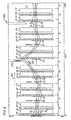
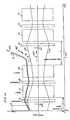
- FIG. 1shows schematically a plan view of a sixfold synchrotron ring of a particle accelerator in one embodiment of the invention
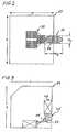
- FIG. 2shows schematically a partial cross-section through one dipole magnet of a pair of dipole magnets of the sixfold synchrotron ring according to FIG. 1 ;
- FIG. 3shows schematically a partial cross-section through a quadrupole magnet of the sixfold synchrotron ring according to FIG. 1 ;
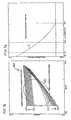
- FIG. 4shows schematically a diagram of the horizontal and vertical beam radii (beam envelopes) in the synchrotron ring according to FIG. 1 ;
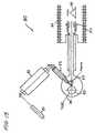
- FIG. 5shows a schematic plan view of an electrostatic injection septum
- FIG. 6shows schematically a diagram of the trajectory displacement of the ion beam in the synchrotron ring according to FIG. 1 under the influence of three bumper magnets in the beam path;
- FIG. 7shows schematically a diagram of a radial acceptance, triggered by bumper magnets, from circulation to circulation of the ion beam, and a parabolic ramp for the magnetic fields of the bumper magnets;
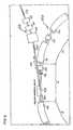
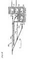
- FIG. 8shows schematically a plan view of a section of a sixfold synchrotron ring with the extraction branch
- FIG. 9shows schematically a diagram with an exit direction of the extracted ion beam by means of the six individually adjustable sextupole magnets
- FIG. 10shows schematically a diagram with a plurality of different exit directions of the extracted ion beam by means of the six individually adjustable sextupole magnets
- FIG. 11shows schematically a diagram of the beam deflection in the synchrotron ring in the region of an extraction means
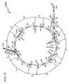
- FIG. 12shows schematically a plan view of a particle accelerator with ion source, injector-linear accelerator, sixfold synchrotron ring and extraction branch in one embodiment of the invention
- FIG. 13shows schematically a basic outline of an ion source
- FIG. 14shows schematically a basic outline of an injector-linear accelerator
- FIG. 15shows schematically a lateral view of a beam guidance system for a plurality of irradiation sites.
- FIG. 1shows schematically a plan view of a sixfold synchrotron ring 100 of a particle accelerator in one embodiment of the invention.
- the sixfold synchrotron ring 100has for this purpose six rectilinear beam sections 1 to 6 and six curved beam sections 7 to 12 .
- Injection means 43 for introducing a linearly accelerated ion beam 150 into the synchrotron ring 100are arranged on a first rectilinear beam section 1 of the six rectilinear beam sections 1 to 6 .
- Extraction means 45 for extracting the ion beam, rapidly accelerated after several circulations, in the beam direction 151are provided on a third rectilinear beam section 4 .
- each curved beam section 7 to 12comprises a pair of dipole magnets 13 / 14 , 15 / 16 , 17 / 18 , 19 / 20 , 21 / 22 and 23 / 24 .
- a horizontally defocusing quadrupole magnet 31 to 36is arranged between the two dipole magnets of a pair of dipole magnets 13 / 14 , 15 / 16 , 17 / 18 , 19 / 20 , 21 / 22 , 23 / 24 respectively.
- a horizontally focusing quadrupole magnet 25 to 30is moreover arranged upstream of each pair of dipole magnets 13 / 14 , 15 / 16 , 17 / 18 , 19 / 20 , 21 / 22 and 23 / 24 .
- the synchrotronthus has an optimum arrangement of dipole magnets 13 to 24 as bending magnets 46 and quadrupole magnets 25 to 36 .
- FIG. 2shows schematically a partial cross-section through one dipole magnet 13 of a pair of dipole magnets 13 / 14 i.e. bending magnet pair of the sixfold synchrotron ring 100 according to FIG. 1 , just one laterally reversed half 50 of the dipole magnet 13 being shown.
- the dimensionsare specified by way of example in millimetres.
- the elliptical aperture profile 54 enclosed by pole pieces and the magnet coil configuration 49are characteristic of this combination of window-frame and H-magnet type, which can be created only on the basis of the inventive shortened curved beam sections per dipole magnet of the synchrotron ring.
- An optimum construction of the dipole magnet 13 with regard to the required magnet apertures a x in the horizontal direction and a y in the vertical direction in the synchrotronis achieved by the inventive optimised technical design of the bending and quadrupole magnets.
- FIG. 3shows schematically a partial cross-section through a quadrupole magnet 25 of the sixfold synchrotron ring 100 according to FIG. 1 .
- FIG. 3shows merely a quadrant 56 of the quadrupole magnet in cross-section.
- the dimensionsare specified by way of example in millimetres.
- This schematic cross-sectionillustrates the construction of the quadrupole magnet 25 with a rectangular profile and correspondingly small overall breadth.
- the magnetic coil configuration 49 and the pole piece configuration 55differ from that of the dipole magnet 13 in FIG. 2 and are optimised with regard to weight and also with regard to the stored energy and the energy consumption during operation of the synchrotron.
- FIG. 4shows schematically a diagram with horizontal beam radii in the x-direction with curve A and with vertical beam radii in the y-direction with curve B, each of which are plotted in millimetres on the ordinate of the diagram.
- Components having the same functions as in the preceding Figuresare marked with the same reference numerals and are not discussed separately.
- the trajectory length b in millimetres in the synchrotron ringis represented along the abscissa of the diagram.
- the beam deflections in the x and y directions in millimetresare, with comparable side constraints vis-à-vis known synchrotron rings, distinctly smaller, so that advantageously smaller aperture dimensions a x and a y , as shown in FIG. 2 , can be achieved with this invention.
- FIG. 5shows a schematic plan view of an electrostatic injection septum 157 , which belongs to the injection system according to the invention for the synchrotron.
- the dot-dash line 158indicates the position of the trajectory centre of a rectilinear beam section into which, by means of the injection means 43 shown in FIG. 1 , an ion beam 150 is to be injected in the multi-turn injection method.
- the injection septum 157 according to the inventionis designed so that a reproducible operation with minimum beam loss can be automatically set.
- the electrostatic injection septum 157has an optimum geometry with beam entry 154 in the centre of the aperture of the electrostatic injection septum 157 for the incident ion beam 152 and beam exit 155 at the inner electrode 156 of the injection septum 157 for the outgoing ion beam 153 , and a precise setting of beam position and beam angle at the beam exit 155 is achieved by adjusting two parameters, namely, deflection voltage at the electrostatic injection septum 157 and angle of incidence of the injected ion beam 150 at the beam entry 154 into the injection septum 157 .
- the electrostatic injection septum 157comprises curved electrostatic deflectors 159 , the radii of curvature R of which are larger than the trajectory radius r of the pre-accelerated, injected and deflected ion beam 150 .
- FIG. 6shows schematically a diagram of the trajectory displacements of the ion beam 150 in the synchrotron ring 100 according to FIG. 1 under the influence of three bumper magnets 51 , 52 and 53 in the beam path.
- This trajectory displacement with the beam envelope A 1 , A 3 around the beam centre A 2manages with three fast ferrite magnets to produce a local trajectory interruption outside the injection section 1 in the synchrotron, instead of the arrangement known in the art with one of the there bumper magnets in the injection section 1 .
- two bumper magnets 52 and 53 in the straight sections 5 and 6are inserted in the beam direction 151 before the injection section 1 with the injection septum 157 , and one bumper magnet 51 is inserted after the rectilinear injection section 1 , so that the injection section 1 tightly packed with the injection septum 157 shown in FIG. 5 , the sextupole magnet 37 and the horizontally focusing quadrupole magnet 25 , advantageously remains free of bumper magnets.
- the two first bumper magnets 52 and 53can be replaced by a single bumper magnet.
- FIG. 7shows schematically, in FIG. 7 a , a diagram of the phase space 160 of a radial acceptance improving from circulation to circulation (N 4 to N 15 ) of the ion beam, the angle co-ordinates of the phase space 160 being shown in mrad on the ordinate and the location co-ordinates x being shown in mm on the abscissa.
- the ellipse 161shows the achievable optimum adjustment of the beam emittance of the injected ion beam and the acceptance variable from circulation to circulation N 4 to N 15 for the multi-turn injection.
- This radial acceptanceis initiated by the three bumper magnets 51 , 52 and 53 , as shown in FIG. 6 , by means of a parabolic ramp C, shown in FIG. 7 b , for the magnetic fields of the bumper magnets.
- the diagram in 7 bshows the relative intensity of the bumper magnetic field of the bumper magnets 51 , 52 and 53 on the ordinate and the number of circulations N 1 to N 35 on the abscissa.
- the parabolic ramp C for the magnetic fields of the bumper magnetsinitially has a steep drop and a course that flattens out at the end of the ramp C.
- injection means 43 according to the invention for what is termed multi-turn injectionis improved as follows:
- FIG. 8shows schematically a plan view of a section of a sixfold synchrotron ring 100 with the extraction branch 60 , which branches off a rectilinear beam section 4 or extraction section 4 .
- the beam deflection in the extraction section 4comprises just one single extraction septum magnet 62 , since the dimensions of the dipole magnet 19 of the dipole magnet pair 19 / 20 are reduced by virtue of the inventive synchrotron ring 100 such that the extraction of the ion beam 150 is effected at a shallower angle, unlike the situation in synchrotron rings known in the prior art, where at least two septum magnets are necessary in order, with a larger deflecting angle, to get past the subsequent larger dimensions of the dipole magnets used in the prior art.
- the electromagnetic extraction septum 62can be arranged so that it couples the extracted ion beam 150 into a horizontally deflecting dipole magnet 63 , which delivers the ion beam 150 to two quadrupoles 64 and 65 arranged downstream on the extraction branch 60 and belonging to a high energy ion beam guidance system.
- the extraction systemcomprises an electrostatic extraction septum, which is arranged in the rectilinear beam section 3 upstream of the extraction section 4 .
- sextupoles 37 to 42are arranged in each of the rectilinear beam sections 1 to 6 .
- FIG. 9shows schematically a diagram of an individual emergent ray 71 of the extracted ion beam, the direction D of which can be adjusted in the phase space via excitation of a non-linear resonance achieved by the six sextupoles 37 to 42 shown in FIG. 1 .
- FIG. 9shows a representation of a phase space 170 , the angle co-ordinate x′ being shown on the ordinate of the diagram and the location co-ordinate x being visible on the abscissa of the illustration.
- the ionsbecome unstable and, in the illustration, in the phase space 170 for the movement in the horizontal plane, move with each circulation one step from one of the three arms 71 , 72 , 73 to the next. Looking at the location co-ordinate x, they oscillate around the central desired trajectory 74 until in the last step on the linear lower arm 71 they enter the electrostatic extraction septum 61 shown in FIG. 11 .
- the exit direction D for the extracted ion beamcan be correspondingly adjusted by means of six individually adjustable sextupole magnets and the optimum efficiency for the resonance extraction can be set. In this way the complicated and laborious mechanical-geometrical adjustment of the electrostatic extraction septum 61 shown in FIG. 11 is avoided.
- FIG. 10shows schematically a diagram of a plurality of exit directions D to M of the extracted ion beam in the phase space 170 , which are adjustable by means of the six individually adjustable sextupole magnets.
- FIG. 11shows schematically a diagram of the beam deflection in the synchrotron ring in the region of an extraction means 45 .
- FIGS. 12 to 15components having identical functions to those in the preceding Figures are marked with the same reference numerals and are not separately discussed.
- the trajectory length bis again plotted in millimetres on the abscissa, but exclusively the deflection in the x-direction is plotted in millimetres on the ordinate.
- An electrostatic extraction septum 61is arranged upstream of an electromagnetic extraction septum 62 in the rectilinear beam section 3 .
- the excitation of an extraction resonancehas already been described above, the electrically and hence automatically adjustable sextupole magnets 37 to 42 enabling the exit direction D of the ion beam 150 to be precisely defined.
- FIG. 12shows schematically an overall view of a particle accelerator 200 with ion source 80 , injector-linear accelerator 90 , sixfold synchrotron ring 100 , injection branch 75 and extraction branch 60 of one embodiment of the invention.
- FIG. 13shows schematically a basic outline of an ion source 80 .
- the ion source usedis a laser ion source, which comprises a HeNe laser 81 , which for its part excites a CO 2 laser.
- the laser beamis then directed via an objective 83 onto the surface 88 of a carbon target or target 86 , whereby the surface 88 of the carbon target is atomised to an electrically charged plasma 87 .
- This plasma 87is accelerated in a pre-accelerator 85 .
- This laser ion source 80is especially suitable for generating very short beam pulses 79 of carbon ions less than or equal to 30 ⁇ s at high beam intensity.
- laser ion sources 80offer important advantages over other ion sources:
- FIG. 14shows schematically a basic outline of an injector-linear accelerator 90 .
- the linear accelerator 90is of modular construction with what are termed IH sections 91 to 93 .
- three quadrupole triplets as quadrupole lenses 94 to 96are arranged partially between the IH sections 91 , 92 and 93 .
- the modular construction of the high-frequency systems comprising IH sections 91 to 93is achieved with high-frequency generators of at most 180 kW HF output.
- the arrangement of the quadrupole lenses 95 and 96 outside the vacuum system between the three accelerator sections in the form of the IH sections 91 , 92 and 93allows a simple, easy-to-service assembly of the linear accelerator.
- This linear accelerator 90 of a preferred embodiment of the inventionthus has the following advantages:
- FIG. 15shows schematically a lateral view of a vertically deflected beam guidance system 66 to a plurality of radiotherapy rooms with irradiation sites 67 to 70 .
- the beam guidance system 66can operate between synchrotron and irradiation sites 67 to 70 with a horizontal deflection directly after the synchrotron, or have a separate vertical deflection for distribution of the ion beam 150 to the irradiation sites 67 to 70 .
- the beam guidance system 66 between synchrotron and irradiation sites 67 to 70is equipped either with a compensation of the horizontal dispersion directly after the synchrotron, or, for a distribution to the different irradiation sites 67 to 70 , with a vertical deflection for a separate, independent compensation of the vertical dispersion.
- a high stability of the beam position at the irradiation sites 67 to 70is therewith advantageously achieved.
- this arrangementis illustrated using the example of a beam guidance system 66 for four irradiation sites 67 to 70 , the beam guidance system 66 being designed for three irradiation sites 67 to 69 with the angle of incidence ⁇ at 0° and one irradiation site 70 with the angle of incidence ⁇ at 45° from above.
- the inventionrelates to a particle accelerator for radiotherapy by means of ion beams, wherein by combining optimisations of all the important accelerator components, such as ion sources, injector linear accelerator, synchrotron ring and beam guidance systems, a reduction in investment costs and operating costs and an improvement in operational reliability are achieved. For that purpose, some or all mentioned improvements can be combined.
- a particle accelerator improved in this wayhas the following advantages:
Landscapes
- Health & Medical Sciences (AREA)
- Engineering & Computer Science (AREA)
- Biomedical Technology (AREA)
- Pathology (AREA)
- Nuclear Medicine, Radiotherapy & Molecular Imaging (AREA)
- Radiology & Medical Imaging (AREA)
- Life Sciences & Earth Sciences (AREA)
- Animal Behavior & Ethology (AREA)
- General Health & Medical Sciences (AREA)
- Public Health (AREA)
- Veterinary Medicine (AREA)
- Physics & Mathematics (AREA)
- Plasma & Fusion (AREA)
- Spectroscopy & Molecular Physics (AREA)
- Particle Accelerators (AREA)
- Radiation-Therapy Devices (AREA)
- Acyclic And Carbocyclic Compounds In Medicinal Compositions (AREA)
Abstract
Description
- at least one curved beam section (7 to12) comprises a pair of dipole magnets (13/14,15/16,17/18,19/20,21/22,23/24),
- a horizontally defocusing quadrupole magnet (31 to36) is arranged between the pair of dipole magnets (13/14,15/16,17/18,19/20,21/22,23/24), and
- a horizontally focusing quadrupole magnet (25 to30) is provided upstream of the pair of dipole magnets (13/14,15/16,17/18,19/20,21/22,23/24).
- (a) high beam intensities of more than 1·1010C4+-ions in short beam pulses of 20-30 μs duration,
- (b) long lifetimes of several weeks without service,
- (c) high reliability over many years of operation, and
- (d) favourable investment and operating costs.
- (a) modular construction of the linear accelerator with three short accelerator sections of 1.5-2 m long for what is termed the IH section,
- (b) modular construction of the high-frequency systems with HF generators of at most 180 kW HF output with corresponding simplification compared with systems in the hitherto customary performance category 1-2 MW to 2 MW,
- (c) technically simpler and for service more advantageous installation of the quadrupole lenses between the accelerator sections outside the vacuum system, e.g. through mechanical separation of the quadrupole yoke in a plane of symmetry,
- (d) high reliability over many years of operation, and
- (e) favourable investment and operating costs.
- (a) Reduction in the overall weight of all magnets, for example, to together less than 100 t compared with more than 210 t in the prior art with comparable side constraints of the system for injected and extracted ion beam energy,
- (b) maximum magnet weights of the individual magnets of at most 5 t and, for a bending magnet pair, of at most 10 t, and correspondingly simple mounting and demounting compared with more than 25 t for an individual bending magnet pair in the prior art with comparable side constraints of the system, accompanied by a clear reduction in weight and costs,
- (c) substantial reduction in the required pulse power for the magnet power supplies owing to the smaller aperture of the bending magnet pairs now possible compared with individual bending magnets, and correspondingly lower costs for the construction and operation of the particle accelerator.
- (a) optimum construction at minimal cost,
- (b) high efficiency for the multi-turn injection of about 85%, i.e. minimum beam loss during injection and correspondingly minimum radioactive burden, so that, unlike cyclotron accelerators, this
synchrotron ring 100 according to the invention satisfies the requirements of radiation protection regulations, - (c) safe, reproducible adjustment methods, which are largely automated.
- (a) non-linear, e.g. parabolic ramp C for the bumper magnetic fields with a steep drop at the start of the ramp C and a course that flattens out at the end of the ramp C;
- (b) trajectory displacement by a multi-turn injection system having three optimally arranged so-called
bumper magnets magnets rectilinear sections 5 and6 before theinjection section 1 deflecting theion beam 150 out and athird bumper magnet 51 in therectilinear section 2 after theinjection section 1 deflecting theion beam 150 back in; - (c) instead of the known arrangement with three bumper magnets, wherein one is arranged in the
injection section 1, only two or at most three bumper magnets are used, none of thebumper magnets rectilinear beam section 1 with injection means43; - (d) optimum geometry for the
electrostatic injection septum 157 withbeam entry 154 in the centre of the aperture and beam exit155 at theinner electrode 156 of theinjection septum 157, and with a precise beam setting through adjustment of the two parameters deflection voltage at theelectrostatic injection septum 157 and the angle of incidence, adjusted as far as possible automatically, of the injectedion beam 150 at the entry into theinjection septum 157.
- (a) high beam intensities of more than 1×10¹⁰C4+ ions in
short beam pulses 79, preferably of from 20 μs to 30 μs duration; - (b) long operating life of many weeks without service;
- (c) high reliability over many years of operation, and
- (d) favourable investment and operating costs.
- (a) modular construction of the
linear accelerator 90 with three short accelerating sections of 1.5 m to 2 m long for each so-calledIH section - (b) modular construction of the high-frequency systems with HF generators of at most 180 kW HF output with corresponding simplification compared with systems in the hitherto
customary performance category 1 MW to 2 MW, - (c) technically simpler, and more advantageous for service, installation of the quadrupole lenses between the accelerator sections outside the vacuum system, at least for the
quadrupole triplets 95 and96.
- (a) small magnet apertures with large beam acceptance;
- (b) low magnet weights;
- (c) small pulse powers and low energy consumption for operation of the synchrotron magnets; and
- (d) optimised parameters for the design and for operation of the injection and extraction systems for the ion beam.
- 1-6 Rectilinear beam section
- 7-12 Curved beam section
- 13-24 Dipole magnets
- 13/14 Dipole pair
- 15/16 Dipole pair
- 17/18 Dipole pair
- 19/20 Dipole pair
- 21/22 Dipole pair
- 23/24 Dipole pair
- 25-30 Horizontally focusing quadrupole
- 31-36 Horizontally defocusing quadrupole
- 37-42 Sextupole
- 43 Injection means
- 44 Beam acceleration means
- 45 Extraction means
- 46 Bending magnet
- 47 Focusing magnet
- 48 Defocusing magnet
- 49 Magnet coil configuration
- 50 Laterally reversed half
- 51 Bumper
- 52 Bumper
- 53 Bumper
- 54 Elliptical profile
- 55 Pole piece configuration
- 56 Quadrant
- 60 Extraction branch
- 61 Electrostatic extraction septum
- 62 Electromagnetic extraction septum
- 63 Dipole magnet
- 64 Quadrupole magnet
- 65 Quadrupole magnet
- 66 Beam guidance system
- 67 Irradiation site
- 68 Irradiation site
- 69 Irradiation site
- 70 Irradiation site
- 71 Arm in phase space
- 72 Arm in phase space
- 73 Arm in phase space
- 74 Central beam trajectory
- 75 Injection path
- 79 Beam pulse
- 80 Ion source
- 81 HeNe laser
- 82 CO2laser
- 83 Objective
- 84 Ion-optical lens
- 85 Pre-accelerator
- 86 Target
- 87 Plasma
- 88 Surface of target
- 90 Linear accelerator
- 91 IH section
- 92 IH section
- 93 IH section
- 94 Quadrupole triplet
- 95 Quadrupole triplet
- 96 Quadrupole triplet
- 100 Sixfold synchrotron ring
- 150 Ion beam
- 151 Beam direction in synchrotron ring
- 152 Incident ion beam in an electrostatic extraction septum
- 153 Emergent beam from an injection septum
- 154 Beam entry
- 155 Beam exit
- 156 Inner electrode
- 157 Injection septum
- 158 dot-dash line
- 159 Deflector
- 160 Phase space
- 161 Ellipse
- 170 Phase pace
- 200 Particle accelerator
- α Irradiation angle
- axMagnet aperture in horizontal direction
- ayMagnet aperture in vertical direction
- A, A1A2, A3Trajectory course with horizontal deflection in x-direction
- B Trajectory course with vertical deflection in y-direction
- b Trajectory length in synchrotron
- C Ramp
- D-M Exit directions
- N1-N35 Circulations of the ion beam
- r Trajectory radius of the injected ion beam
- R Radius of the electrostatic deflector
- x′ Angle co-ordinate
- x Location co-ordinate
Claims (14)
Applications Claiming Priority (4)
| Application Number | Priority Date | Filing Date | Title |
|---|---|---|---|
| DE202004009421UDE202004009421U1 (en) | 2004-06-16 | 2004-06-16 | Particle accelerator for ion beam radiation therapy |
| DE202004009421.5 | 2004-06-16 | ||
| DE202004009421U | 2004-06-16 | ||
| PCT/EP2005/006491WO2005125289A1 (en) | 2004-06-16 | 2005-06-16 | Particle accelerator for radiotherapy by means of ion beams |
Publications (2)
| Publication Number | Publication Date |
|---|---|
| US20080290297A1 US20080290297A1 (en) | 2008-11-27 |
| US7906769B2true US7906769B2 (en) | 2011-03-15 |
Family
ID=34971663
Family Applications (1)
| Application Number | Title | Priority Date | Filing Date |
|---|---|---|---|
| US11/629,805Expired - Fee RelatedUS7906769B2 (en) | 2004-06-16 | 2005-06-16 | Particle accelerator for radiotherapy by means of ion beams |
Country Status (8)
| Country | Link |
|---|---|
| US (1) | US7906769B2 (en) |
| EP (1) | EP1779712B1 (en) |
| JP (1) | JP4996460B2 (en) |
| CN (1) | CN101023715B (en) |
| AT (1) | ATE506839T1 (en) |
| CA (1) | CA2570399A1 (en) |
| DE (2) | DE202004009421U1 (en) |
| WO (1) | WO2005125289A1 (en) |
Cited By (117)
| Publication number | Priority date | Publication date | Assignee | Title |
|---|---|---|---|---|
| US20090200483A1 (en)* | 2005-11-18 | 2009-08-13 | Still River Systems Incorporated | Inner Gantry |
| US20090309520A1 (en)* | 2008-05-22 | 2009-12-17 | Vladimir Balakin | Magnetic field control method and apparatus used in conjunction with a charged particle cancer therapy system |
| US20090309046A1 (en)* | 2008-05-22 | 2009-12-17 | Dr. Vladimir Balakin | Multi-field charged particle cancer therapy method and apparatus coordinated with patient respiration |
| US20090314960A1 (en)* | 2008-05-22 | 2009-12-24 | Vladimir Balakin | Patient positioning method and apparatus used in conjunction with a charged particle cancer therapy system |
| US20100006106A1 (en)* | 2008-07-14 | 2010-01-14 | Dr. Vladimir Balakin | Semi-vertical positioning method and apparatus used in conjunction with a charged particle cancer therapy system |
| US20100014640A1 (en)* | 2008-05-22 | 2010-01-21 | Dr. Vladimir Balakin | Negative ion beam source vacuum method and apparatus used in conjunction with a charged particle cancer therapy system |
| US20100027745A1 (en)* | 2008-05-22 | 2010-02-04 | Vladimir Balakin | Charged particle cancer therapy and patient positioning method and apparatus |
| US20100046697A1 (en)* | 2008-05-22 | 2010-02-25 | Dr. Vladmir Balakin | X-ray tomography method and apparatus used in conjunction with a charged particle cancer therapy system |
| US20100059687A1 (en)* | 2008-05-22 | 2010-03-11 | Vladimir Balakin | Proton beam positioning verification method and apparatus used in conjunction with a charged particle cancer therapy system |
| US20100060209A1 (en)* | 2008-05-22 | 2010-03-11 | Vladimir Balakin | Rf accelerator method and apparatus used in conjunction with a charged particle cancer therapy system |
| US20100059686A1 (en)* | 2008-05-22 | 2010-03-11 | Vladimir Balakin | Tandem accelerator method and apparatus used in conjunction with a charged particle cancer therapy system |
| US20100091948A1 (en)* | 2008-05-22 | 2010-04-15 | Vladimir Balakin | Patient immobilization and repositioning method and apparatus used in conjunction with charged particle cancer therapy |
| US20100090122A1 (en)* | 2008-05-22 | 2010-04-15 | Vladimir | Multi-field charged particle cancer therapy method and apparatus |
| US20100127184A1 (en)* | 2008-05-22 | 2010-05-27 | Dr. Vladimir Balakin | Charged particle cancer therapy dose distribution method and apparatus |
| US20100133444A1 (en)* | 2008-05-22 | 2010-06-03 | Vladimir Balakin | Charged particle cancer therapy patient positioning method and apparatus |
| US20100141183A1 (en)* | 2008-05-22 | 2010-06-10 | Vladimir Balakin | Method and apparatus coordinating synchrotron acceleration periods with patient respiration periods |
| US20100155621A1 (en)* | 2008-05-22 | 2010-06-24 | Vladmir Balakin | Multi-axis / multi-field charged particle cancer therapy method and apparatus |
| US20100171447A1 (en)* | 2008-05-22 | 2010-07-08 | Vladimir Balakin | Intensity modulated three-dimensional radiation scanning method and apparatus |
| US20100207552A1 (en)* | 2008-05-22 | 2010-08-19 | Vladimir Balakin | Charged particle cancer therapy system magnet control method and apparatus |
| US20100266100A1 (en)* | 2008-05-22 | 2010-10-21 | Dr. Vladimir Balakin | Charged particle cancer therapy beam path control method and apparatus |
| US20110118531A1 (en)* | 2008-05-22 | 2011-05-19 | Vladimir Yegorovich Balakin | Multi-axis charged particle cancer therapy method and apparatus |
| US20110118530A1 (en)* | 2008-05-22 | 2011-05-19 | Vladimir Yegorovich Balakin | Charged particle beam injection method and apparatus used in conjunction with a charged particle cancer therapy system |
| US20110118529A1 (en)* | 2008-05-22 | 2011-05-19 | Vladimir Balakin | Multi-axis / multi-field charged particle cancer therapy method and apparatus |
| US20110133699A1 (en)* | 2004-10-29 | 2011-06-09 | Medtronic, Inc. | Lithium-ion battery |
| US20110147608A1 (en)* | 2008-05-22 | 2011-06-23 | Vladimir Balakin | Charged particle cancer therapy imaging method and apparatus |
| US20110150180A1 (en)* | 2008-05-22 | 2011-06-23 | Vladimir Yegorovich Balakin | X-ray method and apparatus used in conjunction with a charged particle cancer therapy system |
| US20110180720A1 (en)* | 2008-05-22 | 2011-07-28 | Vladimir Yegorovich Balakin | Charged particle beam acceleration method and apparatus as part of a charged particle cancer therapy system |
| US20110184221A1 (en)* | 2008-07-14 | 2011-07-28 | Vladimir Balakin | Elongated lifetime x-ray method and apparatus used in conjunction with a charged particle cancer therapy system |
| US20110182410A1 (en)* | 2008-05-22 | 2011-07-28 | Vladimir Yegorovich Balakin | Charged particle cancer therapy beam path control method and apparatus |
| US20110196223A1 (en)* | 2008-05-22 | 2011-08-11 | Dr. Vladimir Balakin | Proton tomography apparatus and method of operation therefor |
| US20110233423A1 (en)* | 2008-05-22 | 2011-09-29 | Vladimir Yegorovich Balakin | Multi-field charged particle cancer therapy method and apparatus |
| US8093564B2 (en) | 2008-05-22 | 2012-01-10 | Vladimir Balakin | Ion beam focusing lens method and apparatus used in conjunction with a charged particle cancer therapy system |
| US8309941B2 (en) | 2008-05-22 | 2012-11-13 | Vladimir Balakin | Charged particle cancer therapy and patient breath monitoring method and apparatus |
| US8368038B2 (en) | 2008-05-22 | 2013-02-05 | Vladimir Balakin | Method and apparatus for intensity control of a charged particle beam extracted from a synchrotron |
| US8374314B2 (en) | 2008-05-22 | 2013-02-12 | Vladimir Balakin | Synchronized X-ray / breathing method and apparatus used in conjunction with a charged particle cancer therapy system |
| US8378311B2 (en) | 2008-05-22 | 2013-02-19 | Vladimir Balakin | Synchrotron power cycling apparatus and method of use thereof |
| US8399866B2 (en) | 2008-05-22 | 2013-03-19 | Vladimir Balakin | Charged particle extraction apparatus and method of use thereof |
| US8415643B2 (en) | 2008-05-22 | 2013-04-09 | Vladimir Balakin | Charged particle beam acceleration and extraction method and apparatus used in conjunction with a charged particle cancer therapy system |
| US20130138184A1 (en)* | 2011-11-30 | 2013-05-30 | Electronics And Telecommunications Research Institute | Target for generating carbon ions and treatment apparatus using the same |
| US20130221234A1 (en)* | 2012-02-29 | 2013-08-29 | Kabushiki Kaisha Toshiba | Laser ion source |
| US8581523B2 (en) | 2007-11-30 | 2013-11-12 | Mevion Medical Systems, Inc. | Interrupted particle source |
| US8625739B2 (en) | 2008-07-14 | 2014-01-07 | Vladimir Balakin | Charged particle cancer therapy x-ray method and apparatus |
| US8637833B2 (en) | 2008-05-22 | 2014-01-28 | Vladimir Balakin | Synchrotron power supply apparatus and method of use thereof |
| US8688197B2 (en) | 2008-05-22 | 2014-04-01 | Vladimir Yegorovich Balakin | Charged particle cancer therapy patient positioning method and apparatus |
| US8718231B2 (en) | 2008-05-22 | 2014-05-06 | Vladimir Balakin | X-ray tomography method and apparatus used in conjunction with a charged particle cancer therapy system |
| US8791435B2 (en) | 2009-03-04 | 2014-07-29 | Vladimir Egorovich Balakin | Multi-field charged particle cancer therapy method and apparatus |
| US8791656B1 (en) | 2013-05-31 | 2014-07-29 | Mevion Medical Systems, Inc. | Active return system |
| US8841866B2 (en) | 2008-05-22 | 2014-09-23 | Vladimir Yegorovich Balakin | Charged particle beam extraction method and apparatus used in conjunction with a charged particle cancer therapy system |
| US8907309B2 (en) | 2009-04-17 | 2014-12-09 | Stephen L. Spotts | Treatment delivery control system and method of operation thereof |
| US8927950B2 (en) | 2012-09-28 | 2015-01-06 | Mevion Medical Systems, Inc. | Focusing a particle beam |
| US8933650B2 (en) | 2007-11-30 | 2015-01-13 | Mevion Medical Systems, Inc. | Matching a resonant frequency of a resonant cavity to a frequency of an input voltage |
| US8933651B2 (en) | 2012-11-16 | 2015-01-13 | Vladimir Balakin | Charged particle accelerator magnet apparatus and method of use thereof |
| US8952634B2 (en) | 2004-07-21 | 2015-02-10 | Mevion Medical Systems, Inc. | Programmable radio frequency waveform generator for a synchrocyclotron |
| US8963112B1 (en) | 2011-05-25 | 2015-02-24 | Vladimir Balakin | Charged particle cancer therapy patient positioning method and apparatus |
| US8969834B2 (en) | 2008-05-22 | 2015-03-03 | Vladimir Balakin | Charged particle therapy patient constraint apparatus and method of use thereof |
| US8975600B2 (en) | 2008-05-22 | 2015-03-10 | Vladimir Balakin | Treatment delivery control system and method of operation thereof |
| US9056199B2 (en) | 2008-05-22 | 2015-06-16 | Vladimir Balakin | Charged particle treatment, rapid patient positioning apparatus and method of use thereof |
| US9095040B2 (en) | 2008-05-22 | 2015-07-28 | Vladimir Balakin | Charged particle beam acceleration and extraction method and apparatus used in conjunction with a charged particle cancer therapy system |
| US9155186B2 (en) | 2012-09-28 | 2015-10-06 | Mevion Medical Systems, Inc. | Focusing a particle beam using magnetic field flutter |
| US9155911B1 (en) | 2008-05-22 | 2015-10-13 | Vladimir Balakin | Ion source method and apparatus used in conjunction with a charged particle cancer therapy system |
| US9168392B1 (en) | 2008-05-22 | 2015-10-27 | Vladimir Balakin | Charged particle cancer therapy system X-ray apparatus and method of use thereof |
| US9177751B2 (en) | 2008-05-22 | 2015-11-03 | Vladimir Balakin | Carbon ion beam injector apparatus and method of use thereof |
| US9185789B2 (en) | 2012-09-28 | 2015-11-10 | Mevion Medical Systems, Inc. | Magnetic shims to alter magnetic fields |
| US9301384B2 (en) | 2012-09-28 | 2016-03-29 | Mevion Medical Systems, Inc. | Adjusting energy of a particle beam |
| US9498649B2 (en) | 2008-05-22 | 2016-11-22 | Vladimir Balakin | Charged particle cancer therapy patient constraint apparatus and method of use thereof |
| US9545528B2 (en) | 2012-09-28 | 2017-01-17 | Mevion Medical Systems, Inc. | Controlling particle therapy |
| US9579525B2 (en) | 2008-05-22 | 2017-02-28 | Vladimir Balakin | Multi-axis charged particle cancer therapy method and apparatus |
| US9622335B2 (en) | 2012-09-28 | 2017-04-11 | Mevion Medical Systems, Inc. | Magnetic field regenerator |
| US9616252B2 (en) | 2008-05-22 | 2017-04-11 | Vladimir Balakin | Multi-field cancer therapy apparatus and method of use thereof |
| US9661736B2 (en) | 2014-02-20 | 2017-05-23 | Mevion Medical Systems, Inc. | Scanning system for a particle therapy system |
| US9681531B2 (en) | 2012-09-28 | 2017-06-13 | Mevion Medical Systems, Inc. | Control system for a particle accelerator |
| US9682254B2 (en) | 2008-05-22 | 2017-06-20 | Vladimir Balakin | Cancer surface searing apparatus and method of use thereof |
| US9723705B2 (en) | 2012-09-28 | 2017-08-01 | Mevion Medical Systems, Inc. | Controlling intensity of a particle beam |
| US9730308B2 (en) | 2013-06-12 | 2017-08-08 | Mevion Medical Systems, Inc. | Particle accelerator that produces charged particles having variable energies |
| US9737733B2 (en) | 2008-05-22 | 2017-08-22 | W. Davis Lee | Charged particle state determination apparatus and method of use thereof |
| US9737734B2 (en) | 2008-05-22 | 2017-08-22 | Susan L. Michaud | Charged particle translation slide control apparatus and method of use thereof |
| US9737272B2 (en) | 2008-05-22 | 2017-08-22 | W. Davis Lee | Charged particle cancer therapy beam state determination apparatus and method of use thereof |
| US9737731B2 (en) | 2010-04-16 | 2017-08-22 | Vladimir Balakin | Synchrotron energy control apparatus and method of use thereof |
| US9744380B2 (en) | 2008-05-22 | 2017-08-29 | Susan L. Michaud | Patient specific beam control assembly of a cancer therapy apparatus and method of use thereof |
| US9782140B2 (en) | 2008-05-22 | 2017-10-10 | Susan L. Michaud | Hybrid charged particle / X-ray-imaging / treatment apparatus and method of use thereof |
| US9855444B2 (en) | 2008-05-22 | 2018-01-02 | Scott Penfold | X-ray detector for proton transit detection apparatus and method of use thereof |
| US9907981B2 (en) | 2016-03-07 | 2018-03-06 | Susan L. Michaud | Charged particle translation slide control apparatus and method of use thereof |
| US9910166B2 (en) | 2008-05-22 | 2018-03-06 | Stephen L. Spotts | Redundant charged particle state determination apparatus and method of use thereof |
| US9937362B2 (en) | 2008-05-22 | 2018-04-10 | W. Davis Lee | Dynamic energy control of a charged particle imaging/treatment apparatus and method of use thereof |
| US9950194B2 (en) | 2014-09-09 | 2018-04-24 | Mevion Medical Systems, Inc. | Patient positioning system |
| US9962560B2 (en) | 2013-12-20 | 2018-05-08 | Mevion Medical Systems, Inc. | Collimator and energy degrader |
| US9974978B2 (en) | 2008-05-22 | 2018-05-22 | W. Davis Lee | Scintillation array apparatus and method of use thereof |
| US9981147B2 (en) | 2008-05-22 | 2018-05-29 | W. Davis Lee | Ion beam extraction apparatus and method of use thereof |
| US10029124B2 (en) | 2010-04-16 | 2018-07-24 | W. Davis Lee | Multiple beamline position isocenterless positively charged particle cancer therapy apparatus and method of use thereof |
| US10029122B2 (en) | 2008-05-22 | 2018-07-24 | Susan L. Michaud | Charged particle—patient motion control system apparatus and method of use thereof |
| US10037863B2 (en) | 2016-05-27 | 2018-07-31 | Mark R. Amato | Continuous ion beam kinetic energy dissipater apparatus and method of use thereof |
| US10070831B2 (en) | 2008-05-22 | 2018-09-11 | James P. Bennett | Integrated cancer therapy—imaging apparatus and method of use thereof |
| US10086214B2 (en) | 2010-04-16 | 2018-10-02 | Vladimir Balakin | Integrated tomography—cancer treatment apparatus and method of use thereof |
| US10092776B2 (en) | 2008-05-22 | 2018-10-09 | Susan L. Michaud | Integrated translation/rotation charged particle imaging/treatment apparatus and method of use thereof |
| US10143854B2 (en) | 2008-05-22 | 2018-12-04 | Susan L. Michaud | Dual rotation charged particle imaging / treatment apparatus and method of use thereof |
| US10179250B2 (en) | 2010-04-16 | 2019-01-15 | Nick Ruebel | Auto-updated and implemented radiation treatment plan apparatus and method of use thereof |
| US10254739B2 (en) | 2012-09-28 | 2019-04-09 | Mevion Medical Systems, Inc. | Coil positioning system |
| US10258810B2 (en) | 2013-09-27 | 2019-04-16 | Mevion Medical Systems, Inc. | Particle beam scanning |
| US10349906B2 (en) | 2010-04-16 | 2019-07-16 | James P. Bennett | Multiplexed proton tomography imaging apparatus and method of use thereof |
| US10376717B2 (en) | 2010-04-16 | 2019-08-13 | James P. Bennett | Intervening object compensating automated radiation treatment plan development apparatus and method of use thereof |
| US10518109B2 (en) | 2010-04-16 | 2019-12-31 | Jillian Reno | Transformable charged particle beam path cancer therapy apparatus and method of use thereof |
| US10548551B2 (en) | 2008-05-22 | 2020-02-04 | W. Davis Lee | Depth resolved scintillation detector array imaging apparatus and method of use thereof |
| US10556126B2 (en) | 2010-04-16 | 2020-02-11 | Mark R. Amato | Automated radiation treatment plan development apparatus and method of use thereof |
| US10555710B2 (en) | 2010-04-16 | 2020-02-11 | James P. Bennett | Simultaneous multi-axes imaging apparatus and method of use thereof |
| US10589128B2 (en) | 2010-04-16 | 2020-03-17 | Susan L. Michaud | Treatment beam path verification in a cancer therapy apparatus and method of use thereof |
| US10625097B2 (en) | 2010-04-16 | 2020-04-21 | Jillian Reno | Semi-automated cancer therapy treatment apparatus and method of use thereof |
| US10638988B2 (en) | 2010-04-16 | 2020-05-05 | Scott Penfold | Simultaneous/single patient position X-ray and proton imaging apparatus and method of use thereof |
| US10646728B2 (en) | 2015-11-10 | 2020-05-12 | Mevion Medical Systems, Inc. | Adaptive aperture |
| US10653892B2 (en) | 2017-06-30 | 2020-05-19 | Mevion Medical Systems, Inc. | Configurable collimator controlled using linear motors |
| US10675487B2 (en) | 2013-12-20 | 2020-06-09 | Mevion Medical Systems, Inc. | Energy degrader enabling high-speed energy switching |
| US10684380B2 (en) | 2008-05-22 | 2020-06-16 | W. Davis Lee | Multiple scintillation detector array imaging apparatus and method of use thereof |
| US10751551B2 (en) | 2010-04-16 | 2020-08-25 | James P. Bennett | Integrated imaging-cancer treatment apparatus and method of use thereof |
| US10925147B2 (en) | 2016-07-08 | 2021-02-16 | Mevion Medical Systems, Inc. | Treatment planning |
| US11103730B2 (en) | 2017-02-23 | 2021-08-31 | Mevion Medical Systems, Inc. | Automated treatment in particle therapy |
| US11291861B2 (en) | 2019-03-08 | 2022-04-05 | Mevion Medical Systems, Inc. | Delivery of radiation by column and generating a treatment plan therefor |
| US11648420B2 (en) | 2010-04-16 | 2023-05-16 | Vladimir Balakin | Imaging assisted integrated tomography—cancer treatment apparatus and method of use thereof |
| US20240431015A1 (en)* | 2021-06-21 | 2024-12-26 | Board Of Regents, The University Of Texas System | Particle-assisted wakefield electron acceleration devices |
Families Citing this family (26)
| Publication number | Priority date | Publication date | Assignee | Title |
|---|---|---|---|---|
| WO2009039884A1 (en) | 2007-09-26 | 2009-04-02 | Ion Beam Applications S.A. | Particle beam transport apparatus and method of transporting a particle beam with small beam spot size |
| DE102008047197B4 (en) | 2008-09-15 | 2013-01-17 | Bernhard Franczak | Method for radiotherapy with ion beams and particle accelerator for carrying out the method |
| CN101631422B (en)* | 2009-01-12 | 2012-05-23 | 中国科学院近代物理研究所 | Synchrotron with Asymmetric Magnetic Focus Structure |
| US8217596B1 (en)* | 2009-03-18 | 2012-07-10 | Jefferson Science Associates, Llc | Method of controlling coherent synchroton radiation-driven degradation of beam quality during bunch length compression |
| US8153997B2 (en)* | 2009-05-05 | 2012-04-10 | General Electric Company | Isotope production system and cyclotron |
| DE102009023305B4 (en)* | 2009-05-29 | 2019-05-16 | Siemens Aktiengesellschaft | cascade accelerator |
| DE102010008991A1 (en) | 2010-02-24 | 2011-08-25 | Siemens Aktiengesellschaft, 80333 | Accelerator for charged particles |
| DE102010008995A1 (en) | 2010-02-24 | 2011-08-25 | Siemens Aktiengesellschaft, 80333 | DC high voltage source and particle accelerator |
| CN101917815B (en)* | 2010-08-10 | 2012-07-04 | 中国科学院近代物理研究所 | Heavy ion or proton synchrotron with medical deflection magnetic focusing structure |
| CN102469677B (en)* | 2010-11-10 | 2015-01-14 | 北京大基康明医疗设备有限公司 | Method for accelerating electron beam in multistep way and multistep linear accelerator |
| US8436325B2 (en)* | 2011-04-19 | 2013-05-07 | Hitachi, Ltd. | Synchrotron and particle therapy system using the same |
| EP2754336B1 (en)* | 2011-09-06 | 2016-04-27 | GSI Helmholtzzentrum für Schwerionenforschung GmbH | Improved septum magnet |
| US8884256B2 (en)* | 2012-02-13 | 2014-11-11 | Mitsubishi Electric Corporation | Septum magnet and particle beam therapy system |
| JP5787793B2 (en)* | 2012-03-05 | 2015-09-30 | 株式会社東芝 | Ion source |
| CN103517537B (en)* | 2012-06-20 | 2016-03-30 | 中国原子能科学研究院 | Two stripping film individual pen line outbound courses in compact cyclotron |
| US9408290B2 (en)* | 2013-11-30 | 2016-08-02 | Jefferson Science Associates, Llc | Method and apparatus for recirculation with control of synchrotron radiation |
| CN105357856B (en)* | 2015-10-16 | 2017-09-15 | 中国科学院上海应用物理研究所 | Injection device and injection method of medical proton synchrotron |
| CN108112154B (en)* | 2017-12-13 | 2020-05-15 | 惠州离子科学研究中心 | Heavy ion synchrotron |
| SE542451C2 (en)* | 2018-03-12 | 2020-05-05 | Ph Kleven As | PARTICLE BEAM GUIDING SYSTEM AND RELATED RADIOTHERAPY SYSTEM |
| JP7244814B2 (en)* | 2018-04-09 | 2023-03-23 | 東芝エネルギーシステムズ株式会社 | Accelerator control method, accelerator control device, and particle beam therapy system |
| CN109707583A (en)* | 2018-04-23 | 2019-05-03 | 李超 | Pulsed momentum cycle engine |
| CN108478940A (en)* | 2018-04-28 | 2018-09-04 | 合肥中科离子医学技术装备有限公司 | The system for carrying out tumour radiotherapy based on heavy ion cyclotron |
| CN109842986B (en)* | 2019-02-02 | 2021-01-01 | 惠州离子科学研究中心 | Fast-cycle synchrotrons and accelerator systems with uniform transverse beams |
| US20230360819A1 (en)* | 2020-10-30 | 2023-11-09 | National Institutes for Quantum Science and Technology | Carbon ion generating device |
| CN112822830B (en)* | 2020-11-25 | 2023-08-18 | 中国科学院近代物理研究所 | Proton and light ion synchrotrons, therapeutic systems incorporating them and applications |
| CN113209501B (en)* | 2021-06-08 | 2023-06-20 | 兰州科近泰基新技术有限责任公司 | A miniaturized ion beam therapy device |
Citations (7)
| Publication number | Priority date | Publication date | Assignee | Title |
|---|---|---|---|---|
| US4992746A (en) | 1988-04-26 | 1991-02-12 | Acctek Associates | Apparatus for acceleration and application of negative ions and electrons |
| US5200701A (en)* | 1990-09-20 | 1993-04-06 | Siemens Aktiengesellschaft | Magnetic resonance imaging apparatus with regulator for reducing eddy current effects |
| US5285166A (en) | 1991-10-16 | 1994-02-08 | Hitachi, Ltd. | Method of extracting charged particles from accelerator, and accelerator capable of carrying out the method, by shifting particle orbit |
| US6008499A (en)* | 1996-12-03 | 1999-12-28 | Hitachi, Ltd. | Synchrotron type accelerator and medical treatment system employing the same |
| WO2000016342A1 (en) | 1998-09-11 | 2000-03-23 | Gesellschaft Fuer Schwerionenforschung Mbh | Ion beam therapy system and a method for operating the system |
| EP0994638A1 (en) | 1998-10-16 | 2000-04-19 | Hitachi, Ltd. | Charged-particle beam ejection method and apparatus using the method |
| US20020014588A1 (en)* | 2000-07-27 | 2002-02-07 | Kazuo Hiramoto | Accelerator and medical system and operating method of the same |
Family Cites Families (4)
| Publication number | Priority date | Publication date | Assignee | Title |
|---|---|---|---|---|
| JPH0227700A (en)* | 1988-07-15 | 1990-01-30 | Hitachi Ltd | low emittance sling |
| JP3302852B2 (en)* | 1995-01-24 | 2002-07-15 | 株式会社日立製作所 | Accelerator, beam emission control method thereof, and beam emission control device |
| JP3458685B2 (en)* | 1997-12-08 | 2003-10-20 | 三菱電機株式会社 | Charged particle beam equipment |
| DE10010523C2 (en) | 2000-03-07 | 2002-08-14 | Schwerionenforsch Gmbh | Ion beam system for the irradiation of tumor tissue |
- 2004
- 2004-06-16DEDE202004009421Upatent/DE202004009421U1/ennot_activeExpired - Lifetime
- 2005
- 2005-06-16WOPCT/EP2005/006491patent/WO2005125289A1/enactiveApplication Filing
- 2005-06-16CNCN2005800195352Apatent/CN101023715B/ennot_activeExpired - Fee Related
- 2005-06-16DEDE502005011284Tpatent/DE502005011284D1/ennot_activeExpired - Lifetime
- 2005-06-16USUS11/629,805patent/US7906769B2/ennot_activeExpired - Fee Related
- 2005-06-16CACA002570399Apatent/CA2570399A1/ennot_activeAbandoned
- 2005-06-16EPEP05756502Apatent/EP1779712B1/ennot_activeExpired - Lifetime
- 2005-06-16ATAT05756502Tpatent/ATE506839T1/enactive
- 2005-06-16JPJP2007515885Apatent/JP4996460B2/ennot_activeExpired - Fee Related
Patent Citations (8)
| Publication number | Priority date | Publication date | Assignee | Title |
|---|---|---|---|---|
| US4992746A (en) | 1988-04-26 | 1991-02-12 | Acctek Associates | Apparatus for acceleration and application of negative ions and electrons |
| US5200701A (en)* | 1990-09-20 | 1993-04-06 | Siemens Aktiengesellschaft | Magnetic resonance imaging apparatus with regulator for reducing eddy current effects |
| US5285166A (en) | 1991-10-16 | 1994-02-08 | Hitachi, Ltd. | Method of extracting charged particles from accelerator, and accelerator capable of carrying out the method, by shifting particle orbit |
| US6008499A (en)* | 1996-12-03 | 1999-12-28 | Hitachi, Ltd. | Synchrotron type accelerator and medical treatment system employing the same |
| US6087670A (en) | 1996-12-03 | 2000-07-11 | Hitachi, Ltd. | Synchrotron type accelerator and medical treatment system employing the same |
| WO2000016342A1 (en) | 1998-09-11 | 2000-03-23 | Gesellschaft Fuer Schwerionenforschung Mbh | Ion beam therapy system and a method for operating the system |
| EP0994638A1 (en) | 1998-10-16 | 2000-04-19 | Hitachi, Ltd. | Charged-particle beam ejection method and apparatus using the method |
| US20020014588A1 (en)* | 2000-07-27 | 2002-02-07 | Kazuo Hiramoto | Accelerator and medical system and operating method of the same |
Non-Patent Citations (2)
| Title |
|---|
| Hattori et al., Nuclear Instruments and Methods in Physics Research B, 188:221-224 (2002). |
| Office Action corresponding to Chinese Patent Application No. 2005800195352. |
Cited By (178)
| Publication number | Priority date | Publication date | Assignee | Title |
|---|---|---|---|---|
| USRE48047E1 (en) | 2004-07-21 | 2020-06-09 | Mevion Medical Systems, Inc. | Programmable radio frequency waveform generator for a synchrocyclotron |
| US8952634B2 (en) | 2004-07-21 | 2015-02-10 | Mevion Medical Systems, Inc. | Programmable radio frequency waveform generator for a synchrocyclotron |
| US20110133699A1 (en)* | 2004-10-29 | 2011-06-09 | Medtronic, Inc. | Lithium-ion battery |
| US20090200483A1 (en)* | 2005-11-18 | 2009-08-13 | Still River Systems Incorporated | Inner Gantry |
| US8907311B2 (en) | 2005-11-18 | 2014-12-09 | Mevion Medical Systems, Inc. | Charged particle radiation therapy |
| US8344340B2 (en) | 2005-11-18 | 2013-01-01 | Mevion Medical Systems, Inc. | Inner gantry |
| USRE48317E1 (en) | 2007-11-30 | 2020-11-17 | Mevion Medical Systems, Inc. | Interrupted particle source |
| US8970137B2 (en) | 2007-11-30 | 2015-03-03 | Mevion Medical Systems, Inc. | Interrupted particle source |
| US8933650B2 (en) | 2007-11-30 | 2015-01-13 | Mevion Medical Systems, Inc. | Matching a resonant frequency of a resonant cavity to a frequency of an input voltage |
| US8581523B2 (en) | 2007-11-30 | 2013-11-12 | Mevion Medical Systems, Inc. | Interrupted particle source |
| US8969834B2 (en) | 2008-05-22 | 2015-03-03 | Vladimir Balakin | Charged particle therapy patient constraint apparatus and method of use thereof |
| US9937362B2 (en) | 2008-05-22 | 2018-04-10 | W. Davis Lee | Dynamic energy control of a charged particle imaging/treatment apparatus and method of use thereof |
| US20100090122A1 (en)* | 2008-05-22 | 2010-04-15 | Vladimir | Multi-field charged particle cancer therapy method and apparatus |
| US20100127184A1 (en)* | 2008-05-22 | 2010-05-27 | Dr. Vladimir Balakin | Charged particle cancer therapy dose distribution method and apparatus |
| US20100133444A1 (en)* | 2008-05-22 | 2010-06-03 | Vladimir Balakin | Charged particle cancer therapy patient positioning method and apparatus |
| US20100141183A1 (en)* | 2008-05-22 | 2010-06-10 | Vladimir Balakin | Method and apparatus coordinating synchrotron acceleration periods with patient respiration periods |
| US20100155621A1 (en)* | 2008-05-22 | 2010-06-24 | Vladmir Balakin | Multi-axis / multi-field charged particle cancer therapy method and apparatus |
| US20100171447A1 (en)* | 2008-05-22 | 2010-07-08 | Vladimir Balakin | Intensity modulated three-dimensional radiation scanning method and apparatus |
| US20100207552A1 (en)* | 2008-05-22 | 2010-08-19 | Vladimir Balakin | Charged particle cancer therapy system magnet control method and apparatus |
| US20100266100A1 (en)* | 2008-05-22 | 2010-10-21 | Dr. Vladimir Balakin | Charged particle cancer therapy beam path control method and apparatus |
| US20110118531A1 (en)* | 2008-05-22 | 2011-05-19 | Vladimir Yegorovich Balakin | Multi-axis charged particle cancer therapy method and apparatus |
| US20110118530A1 (en)* | 2008-05-22 | 2011-05-19 | Vladimir Yegorovich Balakin | Charged particle beam injection method and apparatus used in conjunction with a charged particle cancer therapy system |
| US20110118529A1 (en)* | 2008-05-22 | 2011-05-19 | Vladimir Balakin | Multi-axis / multi-field charged particle cancer therapy method and apparatus |
| US20100059686A1 (en)* | 2008-05-22 | 2010-03-11 | Vladimir Balakin | Tandem accelerator method and apparatus used in conjunction with a charged particle cancer therapy system |
| US20110147608A1 (en)* | 2008-05-22 | 2011-06-23 | Vladimir Balakin | Charged particle cancer therapy imaging method and apparatus |
| US20110150180A1 (en)* | 2008-05-22 | 2011-06-23 | Vladimir Yegorovich Balakin | X-ray method and apparatus used in conjunction with a charged particle cancer therapy system |
| US9058910B2 (en) | 2008-05-22 | 2015-06-16 | Vladimir Yegorovich Balakin | Charged particle beam acceleration method and apparatus as part of a charged particle cancer therapy system |
| US20090309520A1 (en)* | 2008-05-22 | 2009-12-17 | Vladimir Balakin | Magnetic field control method and apparatus used in conjunction with a charged particle cancer therapy system |
| US20110182410A1 (en)* | 2008-05-22 | 2011-07-28 | Vladimir Yegorovich Balakin | Charged particle cancer therapy beam path control method and apparatus |
| US20110196223A1 (en)* | 2008-05-22 | 2011-08-11 | Dr. Vladimir Balakin | Proton tomography apparatus and method of operation therefor |
| US20110233423A1 (en)* | 2008-05-22 | 2011-09-29 | Vladimir Yegorovich Balakin | Multi-field charged particle cancer therapy method and apparatus |
| US8093564B2 (en) | 2008-05-22 | 2012-01-10 | Vladimir Balakin | Ion beam focusing lens method and apparatus used in conjunction with a charged particle cancer therapy system |
| US8129699B2 (en) | 2008-05-22 | 2012-03-06 | Vladimir Balakin | Multi-field charged particle cancer therapy method and apparatus coordinated with patient respiration |
| US8129694B2 (en) | 2008-05-22 | 2012-03-06 | Vladimir Balakin | Negative ion beam source vacuum method and apparatus used in conjunction with a charged particle cancer therapy system |
| US8144832B2 (en) | 2008-05-22 | 2012-03-27 | Vladimir Balakin | X-ray tomography method and apparatus used in conjunction with a charged particle cancer therapy system |
| US8178859B2 (en) | 2008-05-22 | 2012-05-15 | Vladimir Balakin | Proton beam positioning verification method and apparatus used in conjunction with a charged particle cancer therapy system |
| US8188688B2 (en) | 2008-05-22 | 2012-05-29 | Vladimir Balakin | Magnetic field control method and apparatus used in conjunction with a charged particle cancer therapy system |
| US8198607B2 (en) | 2008-05-22 | 2012-06-12 | Vladimir Balakin | Tandem accelerator method and apparatus used in conjunction with a charged particle cancer therapy system |
| US10684380B2 (en) | 2008-05-22 | 2020-06-16 | W. Davis Lee | Multiple scintillation detector array imaging apparatus and method of use thereof |
| US8288742B2 (en) | 2008-05-22 | 2012-10-16 | Vladimir Balakin | Charged particle cancer therapy patient positioning method and apparatus |
| US8309941B2 (en) | 2008-05-22 | 2012-11-13 | Vladimir Balakin | Charged particle cancer therapy and patient breath monitoring method and apparatus |
| US20100060209A1 (en)* | 2008-05-22 | 2010-03-11 | Vladimir Balakin | Rf accelerator method and apparatus used in conjunction with a charged particle cancer therapy system |
| US8368038B2 (en) | 2008-05-22 | 2013-02-05 | Vladimir Balakin | Method and apparatus for intensity control of a charged particle beam extracted from a synchrotron |
| US8373146B2 (en) | 2008-05-22 | 2013-02-12 | Vladimir Balakin | RF accelerator method and apparatus used in conjunction with a charged particle cancer therapy system |
| US8373145B2 (en) | 2008-05-22 | 2013-02-12 | Vladimir Balakin | Charged particle cancer therapy system magnet control method and apparatus |
| US8373143B2 (en) | 2008-05-22 | 2013-02-12 | Vladimir Balakin | Patient immobilization and repositioning method and apparatus used in conjunction with charged particle cancer therapy |
| US8374314B2 (en) | 2008-05-22 | 2013-02-12 | Vladimir Balakin | Synchronized X-ray / breathing method and apparatus used in conjunction with a charged particle cancer therapy system |
| US8378321B2 (en) | 2008-05-22 | 2013-02-19 | Vladimir Balakin | Charged particle cancer therapy and patient positioning method and apparatus |
| US8378311B2 (en) | 2008-05-22 | 2013-02-19 | Vladimir Balakin | Synchrotron power cycling apparatus and method of use thereof |
| US8384053B2 (en) | 2008-05-22 | 2013-02-26 | Vladimir Balakin | Charged particle beam extraction method and apparatus used in conjunction with a charged particle cancer therapy system |
| US8399866B2 (en) | 2008-05-22 | 2013-03-19 | Vladimir Balakin | Charged particle extraction apparatus and method of use thereof |
| US8415643B2 (en) | 2008-05-22 | 2013-04-09 | Vladimir Balakin | Charged particle beam acceleration and extraction method and apparatus used in conjunction with a charged particle cancer therapy system |
| US8421041B2 (en) | 2008-05-22 | 2013-04-16 | Vladimir Balakin | Intensity control of a charged particle beam extracted from a synchrotron |
| US8436327B2 (en) | 2008-05-22 | 2013-05-07 | Vladimir Balakin | Multi-field charged particle cancer therapy method and apparatus |
| US20090309046A1 (en)* | 2008-05-22 | 2009-12-17 | Dr. Vladimir Balakin | Multi-field charged particle cancer therapy method and apparatus coordinated with patient respiration |
| US8487278B2 (en) | 2008-05-22 | 2013-07-16 | Vladimir Yegorovich Balakin | X-ray method and apparatus used in conjunction with a charged particle cancer therapy system |
| US8519365B2 (en) | 2008-05-22 | 2013-08-27 | Vladimir Balakin | Charged particle cancer therapy imaging method and apparatus |
| US10548551B2 (en) | 2008-05-22 | 2020-02-04 | W. Davis Lee | Depth resolved scintillation detector array imaging apparatus and method of use thereof |
| US8569717B2 (en) | 2008-05-22 | 2013-10-29 | Vladimir Balakin | Intensity modulated three-dimensional radiation scanning method and apparatus |
| US20100059687A1 (en)* | 2008-05-22 | 2010-03-11 | Vladimir Balakin | Proton beam positioning verification method and apparatus used in conjunction with a charged particle cancer therapy system |
| US8581215B2 (en) | 2008-05-22 | 2013-11-12 | Vladimir Balakin | Charged particle cancer therapy patient positioning method and apparatus |
| US8598543B2 (en) | 2008-05-22 | 2013-12-03 | Vladimir Balakin | Multi-axis/multi-field charged particle cancer therapy method and apparatus |
| US8614429B2 (en) | 2008-05-22 | 2013-12-24 | Vladimir Balakin | Multi-axis/multi-field charged particle cancer therapy method and apparatus |
| US8614554B2 (en) | 2008-05-22 | 2013-12-24 | Vladimir Balakin | Magnetic field control method and apparatus used in conjunction with a charged particle cancer therapy system |
| US8624528B2 (en) | 2008-05-22 | 2014-01-07 | Vladimir Balakin | Method and apparatus coordinating synchrotron acceleration periods with patient respiration periods |
| US10143854B2 (en) | 2008-05-22 | 2018-12-04 | Susan L. Michaud | Dual rotation charged particle imaging / treatment apparatus and method of use thereof |
| US10092776B2 (en) | 2008-05-22 | 2018-10-09 | Susan L. Michaud | Integrated translation/rotation charged particle imaging/treatment apparatus and method of use thereof |
| US8637818B2 (en) | 2008-05-22 | 2014-01-28 | Vladimir Balakin | Magnetic field control method and apparatus used in conjunction with a charged particle cancer therapy system |
| US8637833B2 (en) | 2008-05-22 | 2014-01-28 | Vladimir Balakin | Synchrotron power supply apparatus and method of use thereof |
| US8642978B2 (en) | 2008-05-22 | 2014-02-04 | Vladimir Balakin | Charged particle cancer therapy dose distribution method and apparatus |
| US8688197B2 (en) | 2008-05-22 | 2014-04-01 | Vladimir Yegorovich Balakin | Charged particle cancer therapy patient positioning method and apparatus |
| US8710462B2 (en) | 2008-05-22 | 2014-04-29 | Vladimir Balakin | Charged particle cancer therapy beam path control method and apparatus |
| US8718231B2 (en) | 2008-05-22 | 2014-05-06 | Vladimir Balakin | X-ray tomography method and apparatus used in conjunction with a charged particle cancer therapy system |
| US8766217B2 (en) | 2008-05-22 | 2014-07-01 | Vladimir Yegorovich Balakin | Multi-field charged particle cancer therapy method and apparatus |
| US10070831B2 (en) | 2008-05-22 | 2018-09-11 | James P. Bennett | Integrated cancer therapy—imaging apparatus and method of use thereof |
| US10029122B2 (en) | 2008-05-22 | 2018-07-24 | Susan L. Michaud | Charged particle—patient motion control system apparatus and method of use thereof |
| US8841866B2 (en) | 2008-05-22 | 2014-09-23 | Vladimir Yegorovich Balakin | Charged particle beam extraction method and apparatus used in conjunction with a charged particle cancer therapy system |
| US9981147B2 (en) | 2008-05-22 | 2018-05-29 | W. Davis Lee | Ion beam extraction apparatus and method of use thereof |
| US8896239B2 (en) | 2008-05-22 | 2014-11-25 | Vladimir Yegorovich Balakin | Charged particle beam injection method and apparatus used in conjunction with a charged particle cancer therapy system |
| US8901509B2 (en) | 2008-05-22 | 2014-12-02 | Vladimir Yegorovich Balakin | Multi-axis charged particle cancer therapy method and apparatus |
| US20100046697A1 (en)* | 2008-05-22 | 2010-02-25 | Dr. Vladmir Balakin | X-ray tomography method and apparatus used in conjunction with a charged particle cancer therapy system |
| US9974978B2 (en) | 2008-05-22 | 2018-05-22 | W. Davis Lee | Scintillation array apparatus and method of use thereof |
| US9044600B2 (en) | 2008-05-22 | 2015-06-02 | Vladimir Balakin | Proton tomography apparatus and method of operation therefor |
| US20100027745A1 (en)* | 2008-05-22 | 2010-02-04 | Vladimir Balakin | Charged particle cancer therapy and patient positioning method and apparatus |
| US9910166B2 (en) | 2008-05-22 | 2018-03-06 | Stephen L. Spotts | Redundant charged particle state determination apparatus and method of use thereof |
| US8941084B2 (en) | 2008-05-22 | 2015-01-27 | Vladimir Balakin | Charged particle cancer therapy dose distribution method and apparatus |
| US20100014640A1 (en)* | 2008-05-22 | 2010-01-21 | Dr. Vladimir Balakin | Negative ion beam source vacuum method and apparatus used in conjunction with a charged particle cancer therapy system |
| US8957396B2 (en) | 2008-05-22 | 2015-02-17 | Vladimir Yegorovich Balakin | Charged particle cancer therapy beam path control method and apparatus |
| US9855444B2 (en) | 2008-05-22 | 2018-01-02 | Scott Penfold | X-ray detector for proton transit detection apparatus and method of use thereof |
| US9782140B2 (en) | 2008-05-22 | 2017-10-10 | Susan L. Michaud | Hybrid charged particle / X-ray-imaging / treatment apparatus and method of use thereof |
| US20090314960A1 (en)* | 2008-05-22 | 2009-12-24 | Vladimir Balakin | Patient positioning method and apparatus used in conjunction with a charged particle cancer therapy system |
| US8975600B2 (en) | 2008-05-22 | 2015-03-10 | Vladimir Balakin | Treatment delivery control system and method of operation thereof |
| US9682254B2 (en) | 2008-05-22 | 2017-06-20 | Vladimir Balakin | Cancer surface searing apparatus and method of use thereof |
| US20100091948A1 (en)* | 2008-05-22 | 2010-04-15 | Vladimir Balakin | Patient immobilization and repositioning method and apparatus used in conjunction with charged particle cancer therapy |
| US20110180720A1 (en)* | 2008-05-22 | 2011-07-28 | Vladimir Yegorovich Balakin | Charged particle beam acceleration method and apparatus as part of a charged particle cancer therapy system |
| US9056199B2 (en) | 2008-05-22 | 2015-06-16 | Vladimir Balakin | Charged particle treatment, rapid patient positioning apparatus and method of use thereof |
| US9095040B2 (en) | 2008-05-22 | 2015-07-28 | Vladimir Balakin | Charged particle beam acceleration and extraction method and apparatus used in conjunction with a charged particle cancer therapy system |
| US9757594B2 (en) | 2008-05-22 | 2017-09-12 | Vladimir Balakin | Rotatable targeting magnet apparatus and method of use thereof in conjunction with a charged particle cancer therapy system |
| US9155911B1 (en) | 2008-05-22 | 2015-10-13 | Vladimir Balakin | Ion source method and apparatus used in conjunction with a charged particle cancer therapy system |
| US9168392B1 (en) | 2008-05-22 | 2015-10-27 | Vladimir Balakin | Charged particle cancer therapy system X-ray apparatus and method of use thereof |
| US9177751B2 (en) | 2008-05-22 | 2015-11-03 | Vladimir Balakin | Carbon ion beam injector apparatus and method of use thereof |
| US9744380B2 (en) | 2008-05-22 | 2017-08-29 | Susan L. Michaud | Patient specific beam control assembly of a cancer therapy apparatus and method of use thereof |
| US9737272B2 (en) | 2008-05-22 | 2017-08-22 | W. Davis Lee | Charged particle cancer therapy beam state determination apparatus and method of use thereof |
| US9737734B2 (en) | 2008-05-22 | 2017-08-22 | Susan L. Michaud | Charged particle translation slide control apparatus and method of use thereof |
| US9314649B2 (en) | 2008-05-22 | 2016-04-19 | Vladimir Balakin | Fast magnet method and apparatus used in conjunction with a charged particle cancer therapy system |
| US9498649B2 (en) | 2008-05-22 | 2016-11-22 | Vladimir Balakin | Charged particle cancer therapy patient constraint apparatus and method of use thereof |
| US9543106B2 (en) | 2008-05-22 | 2017-01-10 | Vladimir Balakin | Tandem charged particle accelerator including carbon ion beam injector and carbon stripping foil |
| US9737733B2 (en) | 2008-05-22 | 2017-08-22 | W. Davis Lee | Charged particle state determination apparatus and method of use thereof |
| US9579525B2 (en) | 2008-05-22 | 2017-02-28 | Vladimir Balakin | Multi-axis charged particle cancer therapy method and apparatus |
| US9018601B2 (en) | 2008-05-22 | 2015-04-28 | Vladimir Balakin | Multi-field charged particle cancer therapy method and apparatus coordinated with patient respiration |
| US9616252B2 (en) | 2008-05-22 | 2017-04-11 | Vladimir Balakin | Multi-field cancer therapy apparatus and method of use thereof |
| US8229072B2 (en) | 2008-07-14 | 2012-07-24 | Vladimir Balakin | Elongated lifetime X-ray method and apparatus used in conjunction with a charged particle cancer therapy system |
| US8625739B2 (en) | 2008-07-14 | 2014-01-07 | Vladimir Balakin | Charged particle cancer therapy x-ray method and apparatus |
| US8627822B2 (en) | 2008-07-14 | 2014-01-14 | Vladimir Balakin | Semi-vertical positioning method and apparatus used in conjunction with a charged particle cancer therapy system |
| US20100006106A1 (en)* | 2008-07-14 | 2010-01-14 | Dr. Vladimir Balakin | Semi-vertical positioning method and apparatus used in conjunction with a charged particle cancer therapy system |
| US20110184221A1 (en)* | 2008-07-14 | 2011-07-28 | Vladimir Balakin | Elongated lifetime x-ray method and apparatus used in conjunction with a charged particle cancer therapy system |
| US8791435B2 (en) | 2009-03-04 | 2014-07-29 | Vladimir Egorovich Balakin | Multi-field charged particle cancer therapy method and apparatus |
| US8907309B2 (en) | 2009-04-17 | 2014-12-09 | Stephen L. Spotts | Treatment delivery control system and method of operation thereof |
| US10179250B2 (en) | 2010-04-16 | 2019-01-15 | Nick Ruebel | Auto-updated and implemented radiation treatment plan apparatus and method of use thereof |
| US11648420B2 (en) | 2010-04-16 | 2023-05-16 | Vladimir Balakin | Imaging assisted integrated tomography—cancer treatment apparatus and method of use thereof |
| US9737731B2 (en) | 2010-04-16 | 2017-08-22 | Vladimir Balakin | Synchrotron energy control apparatus and method of use thereof |
| US10518109B2 (en) | 2010-04-16 | 2019-12-31 | Jillian Reno | Transformable charged particle beam path cancer therapy apparatus and method of use thereof |
| US10589128B2 (en) | 2010-04-16 | 2020-03-17 | Susan L. Michaud | Treatment beam path verification in a cancer therapy apparatus and method of use thereof |
| US10625097B2 (en) | 2010-04-16 | 2020-04-21 | Jillian Reno | Semi-automated cancer therapy treatment apparatus and method of use thereof |
| US10638988B2 (en) | 2010-04-16 | 2020-05-05 | Scott Penfold | Simultaneous/single patient position X-ray and proton imaging apparatus and method of use thereof |
| US10349906B2 (en) | 2010-04-16 | 2019-07-16 | James P. Bennett | Multiplexed proton tomography imaging apparatus and method of use thereof |
| US10188877B2 (en) | 2010-04-16 | 2019-01-29 | W. Davis Lee | Fiducial marker/cancer imaging and treatment apparatus and method of use thereof |
| US10357666B2 (en) | 2010-04-16 | 2019-07-23 | W. Davis Lee | Fiducial marker / cancer imaging and treatment apparatus and method of use thereof |
| US10751551B2 (en) | 2010-04-16 | 2020-08-25 | James P. Bennett | Integrated imaging-cancer treatment apparatus and method of use thereof |
| US10376717B2 (en) | 2010-04-16 | 2019-08-13 | James P. Bennett | Intervening object compensating automated radiation treatment plan development apparatus and method of use thereof |
| US10555710B2 (en) | 2010-04-16 | 2020-02-11 | James P. Bennett | Simultaneous multi-axes imaging apparatus and method of use thereof |
| US10556126B2 (en) | 2010-04-16 | 2020-02-11 | Mark R. Amato | Automated radiation treatment plan development apparatus and method of use thereof |
| US10029124B2 (en) | 2010-04-16 | 2018-07-24 | W. Davis Lee | Multiple beamline position isocenterless positively charged particle cancer therapy apparatus and method of use thereof |
| US10086214B2 (en) | 2010-04-16 | 2018-10-02 | Vladimir Balakin | Integrated tomography—cancer treatment apparatus and method of use thereof |
| US8963112B1 (en) | 2011-05-25 | 2015-02-24 | Vladimir Balakin | Charged particle cancer therapy patient positioning method and apparatus |
| US8872140B2 (en)* | 2011-11-30 | 2014-10-28 | Electronics And Telecommunications Research Institute | Target for generating carbon ions and treatment apparatus using the same |
| US20130138184A1 (en)* | 2011-11-30 | 2013-05-30 | Electronics And Telecommunications Research Institute | Target for generating carbon ions and treatment apparatus using the same |
| US20130221234A1 (en)* | 2012-02-29 | 2013-08-29 | Kabushiki Kaisha Toshiba | Laser ion source |
| US9251991B2 (en)* | 2012-02-29 | 2016-02-02 | Kabushiki Kaisha Toshiba | Laser ion source |
| US9706636B2 (en) | 2012-09-28 | 2017-07-11 | Mevion Medical Systems, Inc. | Adjusting energy of a particle beam |
| US9155186B2 (en) | 2012-09-28 | 2015-10-06 | Mevion Medical Systems, Inc. | Focusing a particle beam using magnetic field flutter |
| US9185789B2 (en) | 2012-09-28 | 2015-11-10 | Mevion Medical Systems, Inc. | Magnetic shims to alter magnetic fields |
| US10155124B2 (en) | 2012-09-28 | 2018-12-18 | Mevion Medical Systems, Inc. | Controlling particle therapy |
| US8927950B2 (en) | 2012-09-28 | 2015-01-06 | Mevion Medical Systems, Inc. | Focusing a particle beam |
| US9301384B2 (en) | 2012-09-28 | 2016-03-29 | Mevion Medical Systems, Inc. | Adjusting energy of a particle beam |
| US9545528B2 (en) | 2012-09-28 | 2017-01-17 | Mevion Medical Systems, Inc. | Controlling particle therapy |
| US10368429B2 (en) | 2012-09-28 | 2019-07-30 | Mevion Medical Systems, Inc. | Magnetic field regenerator |
| US9723705B2 (en) | 2012-09-28 | 2017-08-01 | Mevion Medical Systems, Inc. | Controlling intensity of a particle beam |
| US10254739B2 (en) | 2012-09-28 | 2019-04-09 | Mevion Medical Systems, Inc. | Coil positioning system |
| US9622335B2 (en) | 2012-09-28 | 2017-04-11 | Mevion Medical Systems, Inc. | Magnetic field regenerator |
| US9681531B2 (en) | 2012-09-28 | 2017-06-13 | Mevion Medical Systems, Inc. | Control system for a particle accelerator |
| US8933651B2 (en) | 2012-11-16 | 2015-01-13 | Vladimir Balakin | Charged particle accelerator magnet apparatus and method of use thereof |
| US8791656B1 (en) | 2013-05-31 | 2014-07-29 | Mevion Medical Systems, Inc. | Active return system |
| US9730308B2 (en) | 2013-06-12 | 2017-08-08 | Mevion Medical Systems, Inc. | Particle accelerator that produces charged particles having variable energies |
| US10258810B2 (en) | 2013-09-27 | 2019-04-16 | Mevion Medical Systems, Inc. | Particle beam scanning |
| US10456591B2 (en) | 2013-09-27 | 2019-10-29 | Mevion Medical Systems, Inc. | Particle beam scanning |
| US10675487B2 (en) | 2013-12-20 | 2020-06-09 | Mevion Medical Systems, Inc. | Energy degrader enabling high-speed energy switching |
| US9962560B2 (en) | 2013-12-20 | 2018-05-08 | Mevion Medical Systems, Inc. | Collimator and energy degrader |
| US9661736B2 (en) | 2014-02-20 | 2017-05-23 | Mevion Medical Systems, Inc. | Scanning system for a particle therapy system |
| US11717700B2 (en) | 2014-02-20 | 2023-08-08 | Mevion Medical Systems, Inc. | Scanning system |
| US10434331B2 (en) | 2014-02-20 | 2019-10-08 | Mevion Medical Systems, Inc. | Scanning system |
| US9950194B2 (en) | 2014-09-09 | 2018-04-24 | Mevion Medical Systems, Inc. | Patient positioning system |
| US10786689B2 (en) | 2015-11-10 | 2020-09-29 | Mevion Medical Systems, Inc. | Adaptive aperture |
| US11786754B2 (en) | 2015-11-10 | 2023-10-17 | Mevion Medical Systems, Inc. | Adaptive aperture |
| US11213697B2 (en) | 2015-11-10 | 2022-01-04 | Mevion Medical Systems, Inc. | Adaptive aperture |
| US10646728B2 (en) | 2015-11-10 | 2020-05-12 | Mevion Medical Systems, Inc. | Adaptive aperture |
| US9907981B2 (en) | 2016-03-07 | 2018-03-06 | Susan L. Michaud | Charged particle translation slide control apparatus and method of use thereof |
| US10037863B2 (en) | 2016-05-27 | 2018-07-31 | Mark R. Amato | Continuous ion beam kinetic energy dissipater apparatus and method of use thereof |
| US10925147B2 (en) | 2016-07-08 | 2021-02-16 | Mevion Medical Systems, Inc. | Treatment planning |
| US12150235B2 (en) | 2016-07-08 | 2024-11-19 | Mevion Medical Systems, Inc. | Treatment planning |
| US11103730B2 (en) | 2017-02-23 | 2021-08-31 | Mevion Medical Systems, Inc. | Automated treatment in particle therapy |
| US10653892B2 (en) | 2017-06-30 | 2020-05-19 | Mevion Medical Systems, Inc. | Configurable collimator controlled using linear motors |
| US11311746B2 (en) | 2019-03-08 | 2022-04-26 | Mevion Medical Systems, Inc. | Collimator and energy degrader for a particle therapy system |
| US11717703B2 (en) | 2019-03-08 | 2023-08-08 | Mevion Medical Systems, Inc. | Delivery of radiation by column and generating a treatment plan therefor |
| US11291861B2 (en) | 2019-03-08 | 2022-04-05 | Mevion Medical Systems, Inc. | Delivery of radiation by column and generating a treatment plan therefor |
| US12161885B2 (en) | 2019-03-08 | 2024-12-10 | Mevion Medical Systems, Inc. | Delivery of radiation by column and generating a treatment plan therefor |
| US12168147B2 (en) | 2019-03-08 | 2024-12-17 | Mevion Medical Systems, Inc. | Collimator and energy degrader for a particle therapy system |
| US20240431015A1 (en)* | 2021-06-21 | 2024-12-26 | Board Of Regents, The University Of Texas System | Particle-assisted wakefield electron acceleration devices |
Also Published As
| Publication number | Publication date |
|---|---|
| JP4996460B2 (en) | 2012-08-08 |
| CN101023715A (en) | 2007-08-22 |
| WO2005125289A1 (en) | 2005-12-29 |
| DE202004009421U1 (en) | 2005-11-03 |
| JP2008503037A (en) | 2008-01-31 |
| ATE506839T1 (en) | 2011-05-15 |
| DE502005011284D1 (en) | 2011-06-01 |
| CA2570399A1 (en) | 2005-12-29 |
| US20080290297A1 (en) | 2008-11-27 |
| EP1779712B1 (en) | 2011-04-20 |
| CN101023715B (en) | 2011-01-19 |
| EP1779712A1 (en) | 2007-05-02 |
Similar Documents
| Publication | Publication Date | Title |
|---|---|---|
| US7906769B2 (en) | Particle accelerator for radiotherapy by means of ion beams | |
| US7432516B2 (en) | Rapid cycling medical synchrotron and beam delivery system | |
| US6855942B2 (en) | Apparatus for pre-acceleration of ion beams used in a heavy ion beam applications system | |
| CN112822830B (en) | Proton and light ion synchrotrons, therapeutic systems incorporating them and applications | |
| US10051721B2 (en) | High frequency compact low-energy linear accelerator design | |
| CN112657072B (en) | Ultrahigh-dose-rate proton treatment device based on linear accelerator and scanning method | |
| US12144100B2 (en) | 3D high speed RF beam scanner for hadron therapy | |
| EP4308222A1 (en) | Use of magnetic elements to shape and defocus charged particle beams | |
| CN116507011B (en) | Miniaturized multi-ion integrated synchrotron | |
| CN117042278A (en) | Medical miniaturized ion accelerator | |
| Yao et al. | A 60 MeV ultra-compact proton accelerator for proton radiation effects in China | |
| Ivanov et al. | Negative ion and neutral beams injectors at the Budker Institute of nuclear physics | |
| Wolf et al. | Heavy ion injector for the CERN Linac 1 | |
| HK1107217A (en) | Particle accelerator for radiotherapy by means of ion beams | |
| Alexeev et al. | Status of the terawatt accumulator accelerator project | |
| Yamada et al. | HIMAC PIG ion source development | |
| Molodozhentsev et al. | The focusing structure of the Prague proton synchrotron for hadron therapy | |
| Ermakov et al. | Design of a linear accelerator with a magnetic mirror on the beam energy of 45 MeV | |
| Zelinsky et al. | Proposals for electron beam transportation channel to provide homogeneous beam density distribution at a target surface | |
| WO2018042539A1 (en) | Circular accelerator | |
| Cho et al. | Feasibility study of a 1-MW pulsed spallation source | |
| Budanov et al. | STATUS OF THE URAL30M LINAC—A NOVEL INJECTOR TO THE ACCELERATOR COMPLEX OF IHEP | |
| Palmer | Proton bunching options | |
| Alexeev et al. | Maintenance of ITEP-TWAC facility operation and machine capabilities development | |
| Photoinjector | EXPERIMENTAL STUDY ON THE ELECTRON SUPERCONDUCTING LINAC AND ITS APPLICATION |
Legal Events
| Date | Code | Title | Description |
|---|---|---|---|
| AS | Assignment | Owner name:GESELLSCHAFT FUER SCHWERIONENFORSCHUNG GMBH, GERMA Free format text:ASSIGNMENT OF ASSIGNORS INTEREST;ASSIGNOR:FRANCZAK, BERNHARD;REEL/FRAME:025421/0800 Effective date:20070212 | |
| STCF | Information on status: patent grant | Free format text:PATENTED CASE | |
| AS | Assignment | Owner name:GESELLSCHAFT FUER SCHWERIONENFORSCHUNG MBH, GERMAN Free format text:ASSIGNMENT OF ASSIGNORS INTEREST;ASSIGNOR:BLASCHE, KLAUS;REEL/FRAME:026014/0969 Effective date:20110201 | |
| FPAY | Fee payment | Year of fee payment:4 | |
| MAFP | Maintenance fee payment | Free format text:PAYMENT OF MAINTENANCE FEE, 8TH YEAR, LARGE ENTITY (ORIGINAL EVENT CODE: M1552); ENTITY STATUS OF PATENT OWNER: LARGE ENTITY Year of fee payment:8 | |
| FEPP | Fee payment procedure | Free format text:MAINTENANCE FEE REMINDER MAILED (ORIGINAL EVENT CODE: REM.); ENTITY STATUS OF PATENT OWNER: LARGE ENTITY | |
| LAPS | Lapse for failure to pay maintenance fees | Free format text:PATENT EXPIRED FOR FAILURE TO PAY MAINTENANCE FEES (ORIGINAL EVENT CODE: EXP.); ENTITY STATUS OF PATENT OWNER: LARGE ENTITY | |
| STCH | Information on status: patent discontinuation | Free format text:PATENT EXPIRED DUE TO NONPAYMENT OF MAINTENANCE FEES UNDER 37 CFR 1.362 | |
| FP | Lapsed due to failure to pay maintenance fee | Effective date:20230315 |