US7905907B2 - Internal structure stabilization system for spanning three or more structures - Google Patents
Internal structure stabilization system for spanning three or more structuresDownload PDFInfo
- Publication number
- US7905907B2 US7905907B2US10/990,221US99022104AUS7905907B2US 7905907 B2US7905907 B2US 7905907B2US 99022104 AUS99022104 AUS 99022104AUS 7905907 B2US7905907 B2US 7905907B2
- Authority
- US
- United States
- Prior art keywords
- rod
- head
- assembly
- anchor
- bone
- Prior art date
- Legal status (The legal status is an assumption and is not a legal conclusion. Google has not performed a legal analysis and makes no representation as to the accuracy of the status listed.)
- Expired - Fee Related, expires
Links
Images


Classifications
- A—HUMAN NECESSITIES
- A61—MEDICAL OR VETERINARY SCIENCE; HYGIENE
- A61B—DIAGNOSIS; SURGERY; IDENTIFICATION
- A61B17/00—Surgical instruments, devices or methods
- A61B17/56—Surgical instruments or methods for treatment of bones or joints; Devices specially adapted therefor
- A61B17/58—Surgical instruments or methods for treatment of bones or joints; Devices specially adapted therefor for osteosynthesis, e.g. bone plates, screws or setting implements
- A61B17/68—Internal fixation devices, including fasteners and spinal fixators, even if a part thereof projects from the skin
- A61B17/70—Spinal positioners or stabilisers, e.g. stabilisers comprising fluid filler in an implant
- A61B17/7001—Screws or hooks combined with longitudinal elements which do not contact vertebrae
- A61B17/7035—Screws or hooks, wherein a rod-clamping part and a bone-anchoring part can pivot relative to each other
- A61B17/7038—Screws or hooks, wherein a rod-clamping part and a bone-anchoring part can pivot relative to each other to a different extent in different directions, e.g. within one plane only
- A—HUMAN NECESSITIES
- A61—MEDICAL OR VETERINARY SCIENCE; HYGIENE
- A61B—DIAGNOSIS; SURGERY; IDENTIFICATION
- A61B17/00—Surgical instruments, devices or methods
- A61B17/16—Instruments for performing osteoclasis; Drills or chisels for bones; Trepans
- A61B17/1604—Chisels; Rongeurs; Punches; Stamps
- A—HUMAN NECESSITIES
- A61—MEDICAL OR VETERINARY SCIENCE; HYGIENE
- A61B—DIAGNOSIS; SURGERY; IDENTIFICATION
- A61B17/00—Surgical instruments, devices or methods
- A61B17/16—Instruments for performing osteoclasis; Drills or chisels for bones; Trepans
- A61B17/1655—Instruments for performing osteoclasis; Drills or chisels for bones; Trepans for tapping
- A—HUMAN NECESSITIES
- A61—MEDICAL OR VETERINARY SCIENCE; HYGIENE
- A61B—DIAGNOSIS; SURGERY; IDENTIFICATION
- A61B17/00—Surgical instruments, devices or methods
- A61B17/16—Instruments for performing osteoclasis; Drills or chisels for bones; Trepans
- A61B17/17—Guides or aligning means for drills, mills, pins or wires
- A61B17/1739—Guides or aligning means for drills, mills, pins or wires specially adapted for particular parts of the body
- A61B17/1757—Guides or aligning means for drills, mills, pins or wires specially adapted for particular parts of the body for the spine
- A—HUMAN NECESSITIES
- A61—MEDICAL OR VETERINARY SCIENCE; HYGIENE
- A61B—DIAGNOSIS; SURGERY; IDENTIFICATION
- A61B17/00—Surgical instruments, devices or methods
- A61B17/32—Surgical cutting instruments
- A61B17/320016—Endoscopic cutting instruments, e.g. arthroscopes, resectoscopes
- A—HUMAN NECESSITIES
- A61—MEDICAL OR VETERINARY SCIENCE; HYGIENE
- A61B—DIAGNOSIS; SURGERY; IDENTIFICATION
- A61B17/00—Surgical instruments, devices or methods
- A61B17/34—Trocars; Puncturing needles
- A61B17/3417—Details of tips or shafts, e.g. grooves, expandable, bendable; Multiple coaxial sliding cannulas, e.g. for dilating
- A61B17/3421—Cannulas
- A—HUMAN NECESSITIES
- A61—MEDICAL OR VETERINARY SCIENCE; HYGIENE
- A61B—DIAGNOSIS; SURGERY; IDENTIFICATION
- A61B17/00—Surgical instruments, devices or methods
- A61B17/56—Surgical instruments or methods for treatment of bones or joints; Devices specially adapted therefor
- A61B17/58—Surgical instruments or methods for treatment of bones or joints; Devices specially adapted therefor for osteosynthesis, e.g. bone plates, screws or setting implements
- A61B17/68—Internal fixation devices, including fasteners and spinal fixators, even if a part thereof projects from the skin
- A61B17/70—Spinal positioners or stabilisers, e.g. stabilisers comprising fluid filler in an implant
- A61B17/7001—Screws or hooks combined with longitudinal elements which do not contact vertebrae
- A61B17/7002—Longitudinal elements, e.g. rods
- A61B17/7004—Longitudinal elements, e.g. rods with a cross-section which varies along its length
- A61B17/7005—Parts of the longitudinal elements, e.g. their ends, being specially adapted to fit in the screw or hook heads
- A—HUMAN NECESSITIES
- A61—MEDICAL OR VETERINARY SCIENCE; HYGIENE
- A61B—DIAGNOSIS; SURGERY; IDENTIFICATION
- A61B17/00—Surgical instruments, devices or methods
- A61B17/56—Surgical instruments or methods for treatment of bones or joints; Devices specially adapted therefor
- A61B17/58—Surgical instruments or methods for treatment of bones or joints; Devices specially adapted therefor for osteosynthesis, e.g. bone plates, screws or setting implements
- A61B17/68—Internal fixation devices, including fasteners and spinal fixators, even if a part thereof projects from the skin
- A61B17/70—Spinal positioners or stabilisers, e.g. stabilisers comprising fluid filler in an implant
- A61B17/7001—Screws or hooks combined with longitudinal elements which do not contact vertebrae
- A61B17/7002—Longitudinal elements, e.g. rods
- A61B17/701—Longitudinal elements with a non-circular, e.g. rectangular, cross-section
- A—HUMAN NECESSITIES
- A61—MEDICAL OR VETERINARY SCIENCE; HYGIENE
- A61B—DIAGNOSIS; SURGERY; IDENTIFICATION
- A61B17/00—Surgical instruments, devices or methods
- A61B17/56—Surgical instruments or methods for treatment of bones or joints; Devices specially adapted therefor
- A61B17/58—Surgical instruments or methods for treatment of bones or joints; Devices specially adapted therefor for osteosynthesis, e.g. bone plates, screws or setting implements
- A61B17/68—Internal fixation devices, including fasteners and spinal fixators, even if a part thereof projects from the skin
- A61B17/70—Spinal positioners or stabilisers, e.g. stabilisers comprising fluid filler in an implant
- A61B17/7001—Screws or hooks combined with longitudinal elements which do not contact vertebrae
- A61B17/7002—Longitudinal elements, e.g. rods
- A61B17/7011—Longitudinal element being non-straight, e.g. curved, angled or branched
- A—HUMAN NECESSITIES
- A61—MEDICAL OR VETERINARY SCIENCE; HYGIENE
- A61B—DIAGNOSIS; SURGERY; IDENTIFICATION
- A61B17/00—Surgical instruments, devices or methods
- A61B17/56—Surgical instruments or methods for treatment of bones or joints; Devices specially adapted therefor
- A61B17/58—Surgical instruments or methods for treatment of bones or joints; Devices specially adapted therefor for osteosynthesis, e.g. bone plates, screws or setting implements
- A61B17/68—Internal fixation devices, including fasteners and spinal fixators, even if a part thereof projects from the skin
- A61B17/70—Spinal positioners or stabilisers, e.g. stabilisers comprising fluid filler in an implant
- A61B17/7001—Screws or hooks combined with longitudinal elements which do not contact vertebrae
- A61B17/7032—Screws or hooks with U-shaped head or back through which longitudinal rods pass
- A—HUMAN NECESSITIES
- A61—MEDICAL OR VETERINARY SCIENCE; HYGIENE
- A61B—DIAGNOSIS; SURGERY; IDENTIFICATION
- A61B17/00—Surgical instruments, devices or methods
- A61B17/56—Surgical instruments or methods for treatment of bones or joints; Devices specially adapted therefor
- A61B17/58—Surgical instruments or methods for treatment of bones or joints; Devices specially adapted therefor for osteosynthesis, e.g. bone plates, screws or setting implements
- A61B17/68—Internal fixation devices, including fasteners and spinal fixators, even if a part thereof projects from the skin
- A61B17/70—Spinal positioners or stabilisers, e.g. stabilisers comprising fluid filler in an implant
- A61B17/7001—Screws or hooks combined with longitudinal elements which do not contact vertebrae
- A61B17/7035—Screws or hooks, wherein a rod-clamping part and a bone-anchoring part can pivot relative to each other
- A61B17/7037—Screws or hooks, wherein a rod-clamping part and a bone-anchoring part can pivot relative to each other wherein pivoting is blocked when the rod is clamped
- A—HUMAN NECESSITIES
- A61—MEDICAL OR VETERINARY SCIENCE; HYGIENE
- A61B—DIAGNOSIS; SURGERY; IDENTIFICATION
- A61B17/00—Surgical instruments, devices or methods
- A61B17/56—Surgical instruments or methods for treatment of bones or joints; Devices specially adapted therefor
- A61B17/58—Surgical instruments or methods for treatment of bones or joints; Devices specially adapted therefor for osteosynthesis, e.g. bone plates, screws or setting implements
- A61B17/68—Internal fixation devices, including fasteners and spinal fixators, even if a part thereof projects from the skin
- A61B17/70—Spinal positioners or stabilisers, e.g. stabilisers comprising fluid filler in an implant
- A61B17/7001—Screws or hooks combined with longitudinal elements which do not contact vertebrae
- A61B17/7035—Screws or hooks, wherein a rod-clamping part and a bone-anchoring part can pivot relative to each other
- A61B17/704—Screws or hooks, wherein a rod-clamping part and a bone-anchoring part can pivot relative to each other the longitudinal element passing through a ball-joint in the screw head
- A—HUMAN NECESSITIES
- A61—MEDICAL OR VETERINARY SCIENCE; HYGIENE
- A61B—DIAGNOSIS; SURGERY; IDENTIFICATION
- A61B17/00—Surgical instruments, devices or methods
- A61B17/56—Surgical instruments or methods for treatment of bones or joints; Devices specially adapted therefor
- A61B17/58—Surgical instruments or methods for treatment of bones or joints; Devices specially adapted therefor for osteosynthesis, e.g. bone plates, screws or setting implements
- A61B17/68—Internal fixation devices, including fasteners and spinal fixators, even if a part thereof projects from the skin
- A61B17/70—Spinal positioners or stabilisers, e.g. stabilisers comprising fluid filler in an implant
- A61B17/7074—Tools specially adapted for spinal fixation operations other than for bone removal or filler handling
- A61B17/7076—Tools specially adapted for spinal fixation operations other than for bone removal or filler handling for driving, positioning or assembling spinal clamps or bone anchors specially adapted for spinal fixation
- A61B17/7082—Tools specially adapted for spinal fixation operations other than for bone removal or filler handling for driving, positioning or assembling spinal clamps or bone anchors specially adapted for spinal fixation for driving, i.e. rotating, screws or screw parts specially adapted for spinal fixation, e.g. for driving polyaxial or tulip-headed screws
- A—HUMAN NECESSITIES
- A61—MEDICAL OR VETERINARY SCIENCE; HYGIENE
- A61B—DIAGNOSIS; SURGERY; IDENTIFICATION
- A61B17/00—Surgical instruments, devices or methods
- A61B17/56—Surgical instruments or methods for treatment of bones or joints; Devices specially adapted therefor
- A61B17/58—Surgical instruments or methods for treatment of bones or joints; Devices specially adapted therefor for osteosynthesis, e.g. bone plates, screws or setting implements
- A61B17/68—Internal fixation devices, including fasteners and spinal fixators, even if a part thereof projects from the skin
- A61B17/70—Spinal positioners or stabilisers, e.g. stabilisers comprising fluid filler in an implant
- A61B17/7074—Tools specially adapted for spinal fixation operations other than for bone removal or filler handling
- A61B17/7083—Tools for guidance or insertion of tethers, rod-to-anchor connectors, rod-to-rod connectors, or longitudinal elements
- A61B17/7085—Tools for guidance or insertion of tethers, rod-to-anchor connectors, rod-to-rod connectors, or longitudinal elements for insertion of a longitudinal element down one or more hollow screw or hook extensions, i.e. at least a part of the element within an extension has a component of movement parallel to the extension's axis
- A—HUMAN NECESSITIES
- A61—MEDICAL OR VETERINARY SCIENCE; HYGIENE
- A61B—DIAGNOSIS; SURGERY; IDENTIFICATION
- A61B17/00—Surgical instruments, devices or methods
- A61B17/56—Surgical instruments or methods for treatment of bones or joints; Devices specially adapted therefor
- A61B17/58—Surgical instruments or methods for treatment of bones or joints; Devices specially adapted therefor for osteosynthesis, e.g. bone plates, screws or setting implements
- A61B17/68—Internal fixation devices, including fasteners and spinal fixators, even if a part thereof projects from the skin
- A61B17/70—Spinal positioners or stabilisers, e.g. stabilisers comprising fluid filler in an implant
- A61B17/7074—Tools specially adapted for spinal fixation operations other than for bone removal or filler handling
- A61B17/7091—Tools specially adapted for spinal fixation operations other than for bone removal or filler handling for applying, tightening or removing longitudinal element-to-bone anchor locking elements, e.g. caps, set screws, nuts or wedges
- A—HUMAN NECESSITIES
- A61—MEDICAL OR VETERINARY SCIENCE; HYGIENE
- A61B—DIAGNOSIS; SURGERY; IDENTIFICATION
- A61B5/00—Measuring for diagnostic purposes; Identification of persons
- A61B5/103—Measuring devices for testing the shape, pattern, colour, size or movement of the body or parts thereof, for diagnostic purposes
- A61B5/107—Measuring physical dimensions, e.g. size of the entire body or parts thereof
- A—HUMAN NECESSITIES
- A61—MEDICAL OR VETERINARY SCIENCE; HYGIENE
- A61B—DIAGNOSIS; SURGERY; IDENTIFICATION
- A61B5/00—Measuring for diagnostic purposes; Identification of persons
- A61B5/45—For evaluating or diagnosing the musculoskeletal system or teeth
- A61B5/4504—Bones
- A—HUMAN NECESSITIES
- A61—MEDICAL OR VETERINARY SCIENCE; HYGIENE
- A61B—DIAGNOSIS; SURGERY; IDENTIFICATION
- A61B17/00—Surgical instruments, devices or methods
- A61B17/34—Trocars; Puncturing needles
- A61B17/3468—Trocars; Puncturing needles for implanting or removing devices, e.g. prostheses, implants, seeds, wires
- A—HUMAN NECESSITIES
- A61—MEDICAL OR VETERINARY SCIENCE; HYGIENE
- A61B—DIAGNOSIS; SURGERY; IDENTIFICATION
- A61B17/00—Surgical instruments, devices or methods
- A61B17/56—Surgical instruments or methods for treatment of bones or joints; Devices specially adapted therefor
- A61B17/58—Surgical instruments or methods for treatment of bones or joints; Devices specially adapted therefor for osteosynthesis, e.g. bone plates, screws or setting implements
- A61B17/68—Internal fixation devices, including fasteners and spinal fixators, even if a part thereof projects from the skin
- A61B17/70—Spinal positioners or stabilisers, e.g. stabilisers comprising fluid filler in an implant
- A61B17/7001—Screws or hooks combined with longitudinal elements which do not contact vertebrae
- A61B17/7002—Longitudinal elements, e.g. rods
- A—HUMAN NECESSITIES
- A61—MEDICAL OR VETERINARY SCIENCE; HYGIENE
- A61B—DIAGNOSIS; SURGERY; IDENTIFICATION
- A61B17/00—Surgical instruments, devices or methods
- A61B17/32—Surgical cutting instruments
- A61B2017/320044—Blunt dissectors
- A—HUMAN NECESSITIES
- A61—MEDICAL OR VETERINARY SCIENCE; HYGIENE
- A61B—DIAGNOSIS; SURGERY; IDENTIFICATION
- A61B90/00—Instruments, implements or accessories specially adapted for surgery or diagnosis and not covered by any of the groups A61B1/00 - A61B50/00, e.g. for luxation treatment or for protecting wound edges
- A61B90/06—Measuring instruments not otherwise provided for
- A61B2090/061—Measuring instruments not otherwise provided for for measuring dimensions, e.g. length
- A—HUMAN NECESSITIES
- A61—MEDICAL OR VETERINARY SCIENCE; HYGIENE
- A61B—DIAGNOSIS; SURGERY; IDENTIFICATION
- A61B90/00—Instruments, implements or accessories specially adapted for surgery or diagnosis and not covered by any of the groups A61B1/00 - A61B50/00, e.g. for luxation treatment or for protecting wound edges
- A61B90/06—Measuring instruments not otherwise provided for
- A61B2090/067—Measuring instruments not otherwise provided for for measuring angles
- A—HUMAN NECESSITIES
- A61—MEDICAL OR VETERINARY SCIENCE; HYGIENE
- A61B—DIAGNOSIS; SURGERY; IDENTIFICATION
- A61B5/00—Measuring for diagnostic purposes; Identification of persons
- A61B5/68—Arrangements of detecting, measuring or recording means, e.g. sensors, in relation to patient
- A61B5/6846—Arrangements of detecting, measuring or recording means, e.g. sensors, in relation to patient specially adapted to be brought in contact with an internal body part, i.e. invasive
- A61B5/6867—Arrangements of detecting, measuring or recording means, e.g. sensors, in relation to patient specially adapted to be brought in contact with an internal body part, i.e. invasive specially adapted to be attached or implanted in a specific body part
- A61B5/6878—Bone
- A—HUMAN NECESSITIES
- A61—MEDICAL OR VETERINARY SCIENCE; HYGIENE
- A61B—DIAGNOSIS; SURGERY; IDENTIFICATION
- A61B5/00—Measuring for diagnostic purposes; Identification of persons
- A61B5/68—Arrangements of detecting, measuring or recording means, e.g. sensors, in relation to patient
- A61B5/6846—Arrangements of detecting, measuring or recording means, e.g. sensors, in relation to patient specially adapted to be brought in contact with an internal body part, i.e. invasive
- A61B5/6879—Means for maintaining contact with the body
- A61B5/6882—Anchoring means
- Y—GENERAL TAGGING OF NEW TECHNOLOGICAL DEVELOPMENTS; GENERAL TAGGING OF CROSS-SECTIONAL TECHNOLOGIES SPANNING OVER SEVERAL SECTIONS OF THE IPC; TECHNICAL SUBJECTS COVERED BY FORMER USPC CROSS-REFERENCE ART COLLECTIONS [XRACs] AND DIGESTS
- Y10—TECHNICAL SUBJECTS COVERED BY FORMER USPC
- Y10T—TECHNICAL SUBJECTS COVERED BY FORMER US CLASSIFICATION
- Y10T74/00—Machine element or mechanism
- Y10T74/22—Miscellaneous
Definitions
- This inventionrelates to bone stabilization systems, and more particularly to systems and methods for immobilizing bony structures such as vertebrae, and even more particularly a device designed to span three or more bony structures.
- the human spineprovides a vast array of functions, many of which are mechanical in nature.
- the spineis constructed to allow nerves from the brain to pass to various portions of the middle and lower body. These nerves, typically called the spinal cord, are located in a region within the spine called the spinal canal. Various nerve bundles emerge from the spine at different locations along the lateral length of the spine. In a healthy spine, these nerves are protected from damage and/or undue pressure thereon by the structure of the spine itself.
- the spinehas a complex curvature made up of a plurality (24 in all) of individual vertebrae separated by intervertebral discs. These discs hold the vertebrae together in a flexible manner so as to allow a relative movement between the vertebrae from front to back and from side to side. This movement then allows the body to bend forward and backward, to twist from side to side, and to rotate about a vertical axis. Throughout this movement, when the spine is operating properly the nerves are maintained clear of the hard structure of the spine.
- the intervertebral discsloose height, become cracked, dehydrated, or herniated. The result is that the disc height is reduced leading to compression of the nerve bundles, causing pain and in some cases damage to the nerves.
- a cage or bone graftis placed in the disc space to preserve, or restore, height and to cause fusion of the vertebral level.
- one or more rods or bracesare placed between the fused vertebrae with the purpose of the rods being to support the vertebrae, usually along the posterior of the spine while fusion takes place.
- anchorswhich are fitted into the pedicle of the vertebrae.
- One type of anchoris a pedicle screw, and such screws come in a variety of lengths, diameters, and thread types.
- the present inventionin one embodiment, describes a method for bracing more than two bones.
- the methodbegins with the insertion of a first and second bone anchors in a first and second bone, respectively.
- the first and second boneswhich can be vertebrae, can have at least one other bone between them.
- the methodthen includes positioning a pre-formed connector having a predefined curvature between the first and second bone anchors, such that the curved portion of the connector is captured by a third bone anchor positioned in the bone between the first and second bones.
- the present inventiondescribes a spine stabilization device utilizing a first bone anchor inserted into a first vertebra, and a second bone anchor inserted into a second vertebra, where there is at least one vertebra between the first and second vertebra.
- the stabilization devicefurther including a pre-formed connector having a predefined curve, such that the connector spans from the first bone anchor to the second bone anchor and has the curved body of the connector captured by at least a third bone anchor inserted into a vertebra between the first and second vertebra.
- the present inventionalso describes an instrument for positioning a bone anchor in space between a first and second bone anchor assemblies.
- the instrumentincludes a mechanism for defining an arc corresponding to the predefined arc of the connector being used.
- the mechanism for defining an arcis connected to first and second ends which can be removably connected to the first and second bone anchors, and includes a length defining mechanism which allows the spacing between the first and second ends to be matched to the spacing between the first and second bone anchors.
- a memberis movably connected to the arc defining mechanism, which can removably hold an extension used in placing the third bone anchor in the correct position in space.
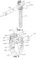
- FIG. 1is a perspective view of an embodiment of an internal stabilization system in accordance with the present invention
- FIG. 2is a perspective view showing a cut-away of the head holding the rod from FIG. 1 ;
- FIG. 3is a perspective view of the head shown in FIG. 2 ;
- FIG. 4shows a sectional view of FIG. 3 taken along line 3 - 3 ;
- FIG. 5is a perspective view of an embodiment of the anchor from FIG. 1 ;
- FIG. 6is a cross-section of the anchor from FIG. 5 showing partially cannulated channel 504 ;
- FIG. 7is a perspective view of the rod from FIG. 1 showing the distal end with a drive mechanism
- FIG. 9is a perspective view of the rod of FIG. 7 mated with the slide ring of FIG. 8 ;
- FIG. 10Ais a cut-away view showing the drive mechanism of the rod of FIG. 7 mated with the anchor of FIG. 5 ;
- FIG. 10Bis an alternate cut-away view of the rod of FIG. 7 capturing the anchor of FIG. 5 in a pocket beyond the receiving threads of the rod;
- FIG. 11is a perspective view of the rod and anchor assembly of FIG. 10A mounted with the head of FIG. 3 ;
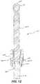
- FIG. 12is a cross-sectional view of FIG. 11 ;
- FIG. 13is a perspective view of the rod, anchor and head assembly of FIG. II where the drive mechanism of the rod has been disengaged from the anchor and rotated within the head;
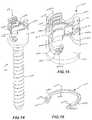
- FIG. 14is a perspective view of an embodiment of a capturing head mounted to an anchor in accordance with the present invention.
- FIG. 15is a detailed perspective view of the capturing head of FIG. 14 ;
- FIG. 16is a perspective view of an embodiment of a clip ring used with the capturing head of FIG. 15 ;
- FIG. 17is a cross-section view of a capturing head mounted on an anchor with a locking cap inserted in the capturing head;
- FIG. 18is a perspective view of a locking cap according to the present invention.
- FIG. 19is a cross-sectional view of the locking cap of FIG. 18 ;
- FIG. 20is a cross-sectional view of the locking cap of FIG. 18 threaded into the capturing head of FIG. 15 ;
- FIG. 21is a cross-sectional view of an embodiment of the locking cap and capturing head employing helical dovetail interlocking threads according to the present invention.
- FIG. 22 ais a cross-sectional view of an anchor, head, rod, and locking cap assembly
- FIG. 22 bis a cross-sectional view of an anchor, capturing head, rod, and locking cap assembly
- FIG. 23is a cross sectional assembly showing an alternate embodiment of a locking cap in relation to a poly-axial head, anchor, rod, and slide ring assembly in accordance with the present invention
- FIG. 24is a cross-section view of the stabilization system of FIG. 1 ;
- FIG. 25is a perspective view of guide wire passing through multiple dilators
- FIG. 26is an exploded perspective view of an obturator in accordance with the present invention.
- FIG. 27is a perspective view of the obturator shown in FIG. 26 ;
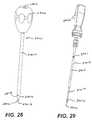
- FIG. 28is a perspective view of an awl in accordance with the present invention.
- FIG. 29is a perspective view of a tap in accordance with the present invention.
- FIG. 30is an exploded perspective view of an extension, cannula assembly in accordance with the present invention.
- FIG. 31is a perspective view of the assembly of FIG. 30 ;
- FIG. 32is a perspective view of the assembly of FIG. 31 rotated 90 degrees;
- FIG. 33is a perspective view of the tube end of the assembly shown in FIG. 30 ;
- FIG. 34is a perspective view of the tube end of FIG. 33 rotated clockwise approximately 90 degrees;
- FIG. 35is a bottom view of the tube end of FIG. 33 illustrating a dovetail channel
- FIG. 36is a perspective view of the drive head from FIG. 30 ;
- FIG. 37is a perspective view of the slide from FIG. 30 ;
- FIG. 38is a perspective view of twist ring 3005 ;
- FIG. 39is a perspective view of the head of FIG. 3 in relation to the tube of FIG. 30 ;
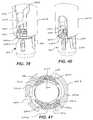
- FIG. 40is a perspective view of the assembly of FIG. 39 with the tube rotated 180 degrees;
- FIG. 41is a cross-sectional bottom view of the assembly of FIG. 39 ;
- FIG. 42is a perspective view of the assembly of FIG. 39 with the tube fully engaged with the head;
- FIG. 43is a cross-sectional bottom view of the assembly of FIG. 42 ;
- FIG. 44is a perspective view of the assembly of FIG. 42 rotated clockwise 90 degrees;
- FIG. 45is a cross-sectional bottom view of the assembly of FIG. 44
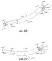
- FIG. 46is a perspective view of an angular measurement tool in accordance with the present invention.
- FIG. 47is a side view of the tool of FIG. 46 in relation to a cutaway view of the assembly of FIG. 30 mated to the head of FIG. 4 and anchor of FIG. 5 ;
- FIG. 48is a perspective view of a driver in accordance with the present invention.
- FIG. 49is an exploded view of the driver of FIG. 48 ;
- FIG. 50is an exploded perspective view of the assembly of FIG. 11 in relation to the assembly of FIG. 30 in relation to the driver of FIG. 48 , and a handle assembly in accordance with the present invention
- FIG. 51is a perspective view of the assemblies of FIG. 50 mated together in accordance with the present invention.
- FIG. 52is a perspective view of an embodiment of a drive tool with a torque screw head in accordance with the present invention.
- FIG. 53is an exploded view of the drive tool of FIG. 52 ;
- FIG. 54is an exploded perspective view of the assembly of FIG. 14 in relation with the assembly of FIG. 30 , the drive tool of FIG. 48 , and a handle assembly in accordance with the present invention
- FIG. 55is a perspective view of the assemblies of FIG. 54 mated together in accordance with the present invention.
- FIG. 56is a perspective view of a tool for locating a second pedicle in accordance with the present invention.
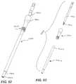
- FIG. 57is a perspective view of a rod transfer tool in accordance with the present invention.
- FIG. 58is a perspective view of the rod transfer tool of FIG. 57 with the distal arm bent upward;
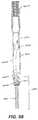
- FIG. 59shows is a perspective view of the distal arm end of the rod transfer tool of FIG. 57 ;
- FIG. 60is a side view of the tip of the distal arm of the rod transfer tool of FIG. 57 ;
- FIG. 61is a side view of the rod transfer tool of FIG. 57 in operation with the assemblies of FIGS. 11 and 30 ;
- FIG. 62is a section view taken through lines a 2 -a 2 of FIG. 61 ;
- FIG. 63is a cut-away view illustrating the orientation of a tine of the rod transfer tool of FIG. 57 with the distal end of the rod of FIG. 9 ;
- FIG. 64is a side view of the rod transfer tool of FIG. 57 operating to transfer a rod from the assembly of FIG. 11 into the capturing head of the assembly of FIG. 14 using the assemblies of FIG. 30 ;
- FIG. 65 ashows a cross-section through section 65 a - 65 a of FIG. 64 ;
- FIG. 65 bshows a cross-section through 65 b - 65 b of FIG. 65 a;
- FIG. 66 ais a perspective view of a drive tool and a counter torque handle in accordance with the present invention, where the drive tool is used to install the locking caps of FIG. 18 ;
- FIG. 66 bis a perspective view of a drive mechanism in accordance with the present invention.
- FIG. 67 ais a perspective view of an embodiment of a rod intended to span three pedicles according to the present invention.
- FIG. 67 bis a perspective view of the rod of FIG. 67 a rotated 180 degrees;
- FIG. 68is a side view of the rod of FIG. 66 mounted to a head and anchor assembly which is mounted to a guide assembly;
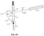
- FIG. 69is a side view of the assembly of FIG. 68 with a tool shown rotating the rod into position;
- FIG. 70is a side view of a three pedicle assembly according to the present invention.
- FIG. 71is a perspective view of an embodiment of a cannula for the three pedicle rod according to the present invention.
- FIG. 72is a perspective view of the assembly of FIG. 70 with the rod spanning three anchor assemblies;
- FIG. 73is a perspective view of the three pedicle assembly with locking caps installed
- FIG. 74is a perspective view of an arc defining instrument for use in multi-pedicle assemblies
- FIG. 75is a perspective view of the back of the instrument shown in FIG. 74 ;
- FIG. 76is front view of the instrument of FIG. 74 with cut away views of extension and poly-axial head assemblies in accordance with the present invention.
- FIG. 77is a perspective view of the instrument and extension and poly-axial head assemblies shown in FIG. 76 .
- An operation to insert a pedicle screw assembly into a patient's back to immobilize certain vertebrae in order to allow bone grafts to ultimately fuse those vertebraebegins with the surgeon inserting a standard bone biopsy needle into the pedicle of a first vertebra and using the bone biopsy needle to place a guide wire where the first pedicle screw should be inserted. Using the guide wire, progressively larger tissue expanders are inserted into the patient to expand, or dilate, the incision to the size necessary to accommodate the instruments to be used, with the final cannula being left in the incision after the smaller ones are removed. (see, FIGS. 25-27 ). Next, an awl ( FIG.
- a tap( FIG. 29 ), having a diameter slightly smaller than the pedicle screw to be used, is inserted down the guide wire and used to tap the hole started by the bone biopsy needle and the awl, making it ready to accept the first pedicle screw.
- a first pedicle screw ( FIG. 5 ) with a poly-axial rod-capturing head ( FIG. 15 ) attached to form a rod-capturing pedicle screw assembly ( FIG. 14 )is inserted down the guide wire using the off-axis screw guide of the pedicle screw and into the hole left by the tap.
- Attached to this pedicle screw assemblyare an extension ( FIGS. 30-32 ) and drive mechanism with a torque head attachment ( FIGS. 52 and 53 ).
- the extensionallows access to the pedicle screw assembly once it is in place.
- the drive mechanismis used to screw the pedicle screw assembly in place and is removed from the extension once the pedicle screw assembly is set to the desired depth.
- a tissue separatoris used to make a path from the first and second, and potentially additional, vertebra where the second pedicle screw assembly will be inserted.
- a bone biopsy needleis used to insert a guide wire into the second vertebra where the second pedicle screw assembly is to be placed.
- a measurement toolFIGS. 46 and 47
- the second pedicle screw assembly( FIG. 11 ) is then chosen according to the proper length of the rod.
- the second pedicle screw assemblyis formed by a pedicle screw identical to the pedicle screw of the first assembly, a poly-axial rod-assembly head ( FIG.
- a drive mechanism with a head to accept the end of the rod( FIGS. 48 and 49 ) is used to drive the second pedicle screw assembly into the pedicle of the second vertebra, using the rod to transfer torque from the drive mechanism to the pedicle screw.
- the pedicle screwis sent along the guide wire using the off-axis screw guide in the pedicle screw.
- the screwis then inserted to the desired depth using the drive mechanism, which is then removed leaving the extension attached to the pedicle screw assembly.
- a rod transfer tool( FIGS. 57 and 58 ) is then inserted into the extension which is attached to the pedicle screw assembly with the poly-axial rod-assembly head until the distal end of the rod transfer tool ( FIG. 59 ) locks with the end of the rod ( FIGS. 60 and 61 ).
- the rod transfer toolis then used to disengage the rod from the drive mechanism of the pedicle screw, and guide the rod down into the extension holding the pedicle screw assembly with the poly-axial rod-capturing head, the end of rod ultimately being pressed down into the poly-axial rod-capturing head, where it is held in place by a clip ring ( FIG. 16 ) in the rod-capturing head.
- the rod transfer toolis removed and locking caps ( FIG. 18 ) are screwed into each of the poly-axial heads using a drive tool and counter torque handle assembly ( FIG. 65 c ).
- the counter torque handleis used to provide a counter torque force to the torque applied by the drive tool, thereby preventing the loading of the rod assembly with torque when the locking caps are tightened into place.
- the extensionsare removed leaving the stabilization system ( FIG. 1 ) in place. Bone grafts can then be placed between the two stabilized vertebrae which will then grow to fuse the vertebrae together while the stabilization system holds the vertebral segment.
- stabilization systemsmay be employed that rigidly connect three or more vertebrae.
- FIG. 73the outer poly-axial head assemblies are inserted into the first and second vertebrae, which surround the third vertebra, as described above.
- an arc defining toolFIG. 74 is required since the rod has a predefined curvature and the third, or middle, poly-axial head assembly must be precisely located to capture the middle of the rod when it is transferred.
- the end of the rod with the drive mechanismis formed with an angle to the drive mechanism to minimize the diameter of the extension required.
- the additional length of the rodalso requires a different rod transfer tool to move the rod into position in the poly-axial head assemblies ( FIG. 70 ), and an extension for the middle poly-axial head assembly ( FIG. 71 ).
- FIG. 1shows stabilization assembly 10 which includes poly-axial head assemblies 100 and 200 shown interconnected by rod 700 .
- Rod 700is shown fastened securely to assemblies 100 and 200 by locking caps 1800 .
- poly-axial rod capturing assembly 100is anchored in the patient's pedicle by anchor 500 along a guide wire which passes through off axis screw guide 504 in anchor 500 .
- anchor 500When assembly 100 is positioned, a measurement is taken to the pedicle where the second assembly is to be positioned. This measurement determines the length of rod 700 .
- the poly-axial rod-assembly 200 with proper size rod 700is chosen and assembly 200 , with anchor 500 attached to head 300 , is positioned in the selected other pedicle with torque being applied to anchor 500 through drive mechanism in distal end 702 of rod 700 which, at that point, is in-line with the longitudinal axis of assembly 200 . From the in-line position, rod 700 is rotated such that it has an end captured by poly-axial rod-capturing head 1500 .
- any type of connector for connecting anchor assemblies 100 and 200could be used and is within the scope of the present invention.
- Such connectorscould include any rod, implant, fastener, or brace used for the purpose of connecting anchors mounted in bony structures.
- Further such connectorsmay be rigid, as rod 700 , may be elastic, as bands, cables or artificial ligaments, or may be dynamic such as the dynamic brace described in U.S. patent application Ser. No. 10/914,751 filed Aug. 9, 2004 and entitled SYSTEM AND METHOD FOR DYNAMIC SKELETAL STABILIZATION, which is herein incorporated by reference.
- FIG. 2shows assembly 200 and it has poly-axial head 300 , anchor 500 , rod 700 and slide ring 800 .
- Slide ring 800allows rod 700 to translate in position so that proximal end 701 can be carefully adjusted to fit into poly-axial rod capturing head 1500 of assembly 100 as shown in FIG. 1 .
- Rod 700includes a distal end 702 with a drive mechanism, and a proximal end 701 shaped such that is can be captured by poly-axial rod-capturing head 1500 shown in FIG. 1 .
- FIG. 3shows poly-axial rod-assembly head 300 having main body 316 and arms 318 a and 318 b . Arms 318 a, b are created by channel 320 on the center line of poly-axial head 300 .
- a boreextends through the longitudinal center line of poly-axial head 300 and the bore has a spherical portion having threads 324 cut therein. As will be seen with reference to FIGS. 10 a and 10 b , the spherical portion allows the head to rotate about the top of a bone anchor while threads 324 allow head 300 to gain access to, and interconnect to the head of the bone screw.
- Head 300also has channels 326 a and 326 b in opposing arms 318 a, b , which arms receive slide ring pins of bracket 800 as will be described. Head 300 also has machined surfaces 328 a and 328 b . These surfaces allow for locking onto a guide tip or extensions to be described hereinafter. Surfaces 328 a, b have torquing surfaces 330 a and 330 b for locking purposes, also to be described hereinafter. Arm 318 b also has cuts 332 and 334 , which accept locking member 3700 , shown in FIG. 37 to enable locking of extensions to head 300 as will be described in greater detail with reference to FIGS. 30-32 .
- Machined surface 328 aalso includes a recessed area 336 which is positioned as a keyway to allow an extension to be locked onto head 300 in only one direction. Therefore surface 336 is constructed only on surface 328 a and not on surface 328 b .
- Head 300also includes screw threads 338 for receiving locking cap 1800 of FIG. 18 .
- FIG. 4shows a sectional view of FIG. 3 taken along line 3 - 3 , and illustrates spherical portion 350 with threads 324 , and cylindrical portion 352 formed by interior wall 401 .
- Spherical portion 350 with threads 324allow the threaded portion of anchor 500 from FIGS. 1 and 5 , to be threaded onto head 300 .
- the threaded portion of anchor 500becomes captured in cylindrical portion 352 , thereby allowing anchor 500 to move in relation to head 300 up to a 30° angle from the center line, which translates into 60 degrees of conical freedom. While 60 degrees of conical freedom is described with reference to the preferred embodiment, any amount of poly axial movement is well within the scope of the present invention.
- FIG. 5illustrates anchor 500 , which in this embodiment is a screw having threads 506 which are inserted into the pedicle or other bony structure. While anchor 500 is shown as a screw, any other type of anchor that could be inserted into a pedicle of a vertebra is within the scope of the present invention.
- Anchor 500also includes screw threads 501 which thread in the opposite direction from threads 506 for attaching anchor 500 to head 300 shown in FIG. 4 .
- Anchor 500also includes a torque transfer drive mechanism 505 , which mates with torque transfer drive 706 shown in FIG. 7 , used in driving anchor 500 into the pedicle of the spine.
- Anchor 500also includes stop limiting collar 502 , which is slightly larger in diameter then spherical portion 350 of head 300 shown in FIG. 4 , allowing head 510 with threads 501 of anchor 500 to be movably held by cylindrical portion 352 of head 300 , thereby allowing rotation of head 300 in relation to anchor 500 .
- anchor 500also includes threads 506 which are bone threads used to purchase anchor 500 into a pedicle. Included near the distal end of anchor 500 is off-axis screw guide 504 , which is a cylindrical bore passing through the treads 506 of anchor 500 and out tip 512 . This bore is used to pass anchor 500 down a guide wire to direct the anchor into a pre-tapped hole in the pedicle as discussed.
- FIG. 6is a cross-section of anchor 500 showing off-axis screw guide 504 .
- This channelat its distal end 601 , receives a guide wire, the end of which is positioned within the tapped hole in the bone. The screw is passed down the guide wire until distal end 601 enters the tapped hole in the pedicle.
- Off-axis screw guide 504is at angle alpha from the center line of anchor 500 . Alpha can be any small angle, but is preferably in the range of 10°-15°.
- the off-axis screw guide 504allows for the benefit of placing the screw in the tapped hole using a guide wire, while preserving the strength of a non-cannulated screw.
- the guide wireis removed and the screw can then be screwed into the pre-tapped hole in the pedicle.
- FIG. 6also illustrates drive mechanism 505 for engagement by drive surfaces of tightening tools, such as the drive tool shown in FIG. 52 or the drive mechanism of rod 700 shown in FIG. 7 , for driving anchor 500 into the bone.
- Stop limiting collar 502allows a mated head, such as poly-axial rod-assembly head 300 from FIG. 3 or poly-axial rod-capturing head 1500 from FIG. 15 , to have a poly-axial motion with respect to anchor 500 .
- a bone biopsy needleinto the bone. Then the top portion of the bone biopsy needle is removed and pulled out leaving a cannula (an open tube) extending from outside the patient down to the newly created hole in the bone.
- a guide wirewhich can have a diameter on the order of two millimeters, is passed down inside the cannula and over the guide wire and dilators are sent down to create a passageway between the muscle tissue.
- the anchoror bone screw
- a cannulated screwis used with a hole all the way through the longitudinal axis. Because some of the screws can be as small as 5.5 millimeters on the major diameter, the minor diameter is extremely small. Consequently, only a very small hole will work because otherwise the screw loses strength. Thus, the holes tend to be small, on the order of 1 millimeter. However, even with a cannulation of 1 millimeter the screws may break, either as a result of misplacement, or when they are used on heavy or active patients. Also, a small cannulation diameter requires a small guide wire, which in turn creates several problems for the surgeon. Small wires can kink, or become bent, or get caught when the screw is being advanced.
- the anchor of the present inventionwhich is formed with the off-axis screw guide, together with a cannula with a groove down its entire length allows the guide wire to remain outside the cannula while the screw is within the cannula. This allows for much thicker guide wires to be used, for example 2 millimeters in diameter, without sacrificing the strength of the screw or having guide wire issues of kinking or wire advancement while the screw is being positioned.
- FIG. 7illustrates rod 700 which has distal end 702 in which drive mechanism 706 is positioned.
- Drive mechanism 706mates with drive mechanism 505 as shown in FIG. 12 .
- Rod 700also includes rod curved body portion 703 in which the rod is partially curved to conform to a patient. Sliding surfaces 705 are constructed to engage with slide ring 800 ( FIG. 8 ).
- Proximal end 701 of rod 700must accomplish at least two functions, first driving the rod/poly-axial head assembly as an extension of a driver, such as the one shown in FIG. 48 , and second being captured by poly-axial rod-capturing assembly 1500 shown in FIG. 15 , which allows for the repositioning of rod 700 from the in-line position shown in FIG. 11 to the “horizontal” position for mating with assembly 100 as shown in FIG. 1 .
- rod 700has driving surface 710 to engage a special head of the driving tool shown as head 4901 in FIG. 49 .
- Driving surface 710engages with the head of the driving tool and allows torque to be transferred from the driving tool through rod 700 and into anchor 500 which is then screwed into a pedicle or other bony structure.
- Opposing drive surface 710is locking surface 714 which is designed to engage with the bottom surface of locking cap 1800 from FIG. 18 . The locking of rod 700 using locking caps 1800 will be discussed in greater detail with reference to FIGS. 22 and 23
- Proximal end 701 of rod 700also includes spherical portion 711 having a diameter larger than the diameter of rod 700 for the purposes of allowing the cavity of poly-axial rod-capturing head 1500 ( FIG. 15 ) to capture rod 700 and to keep the spherical portion 711 engaged with head 1500 as will be discussed with greater detail with respect to FIG. 15 .
- Proximal end of rod 700must also be capable of being captured by rod transfer tool 5700 shown in FIG. 57 , such that the rod transfer tool is engaged with rod 700 until it is nearing the horizontal position at which point rod 700 must disengage from the rod transfer tool so that it may be engaged with the poly-axial rod-capturing head.
- Rod transfer tool engagement mechanism 720which is duplicated on the opposing side of spherical portion 711 includes ramp 715 which allows tines 5905 a and b from FIG.
- tines 5905 a and b of rod transfer tool 5700While engaged in recess 713 , tines 5905 a and b are free to rotate about an axis normal to flats 712 a and 712 b.
- locking capscan be inserted into each of heads 300 and 1500 , such that the ends of the locking caps are engaged with locking surfaces 714 and 704 .
- Locking surfaces 714 and 704are preferably curved to have locking cap 1800 , shown in FIG. 18 , not force rod 700 into a position that is normal to the bottom of the locking cap, but rather a position that allows rod 700 to assume its natural rotation. Thereby allowing for installation of the rod in positions that accounts for variations in anatomical positioning of the vertebral bodies.
- FIG. 8illustrates slide ring 800 which includes main body cylindrical portion 805 , and extension dog-ear tines 802 a and 802 b .
- Dog-ear tines 802 a , and ballow rod 700 to register with racetrack openings 326 a, b of head 300 as shown in FIG. 3 . This facilitates up-down movement of rod 700 with respect to assembly 200 ( FIG. 1 ). This then allows for a variation in height of the rod to occur when the rod is in process of being translated from an in-line position to an approximately 90 degree position for engaging rod-capturing assembly 100 .
- slide ring 800includes a portion having flats 803 a , 803 b and 803 c and partial flats 806 a and 806 b forming a hexagonal saddle in which sliding surfaces 705 rest. While a hexagonal saddle is shown, any shape of saddle may be used that captures rod 700 in a manner that prevents rotation of rod 700 within the slide ring and allows rod 700 to slide freely therein. As stated, these surfaces are constructed to allow slide ring 800 to mate with flats 705 of rod 700 and to allow rod 700 to slide in head 300 while being held by slide ring 800 which in turn is held by ears 802 a and 802 b inside openings 326 a and 326 b , respectively, of head 300 . Surface 804 is used to contact anchor 500 from FIG. 5 during the locking of the poly-axial head assembly, which will be discussed in greater detail with reference to FIG. 22 a
- FIG. 9shows rod 700 mated with slide ring 800 which allows rod 700 to move laterally with respect to slide ring 800 .
- the preferred distance of such movementapproximately 1 centimeter of translation, is allowed along track 705 .
- approximately 15 millimeters of translationis required for multilevel procedures, discussed with reference FIGS. 67-77 .
- FIGS. 10 a and bshow the mating of head 300 with anchor 500 , with the following description applying also to the mating of head 1500 from FIG. 15 with anchor 500 .
- Anchor 500has stop limiting collar 502 and threads 501 .
- threads 324 in spherical portion 350 of head 300 advance beyond threads 501spherical portion 510 of anchor 500 becomes captured by cylindrical portion 352 of head 300 .
- This allows angulation, shown in FIG. 10 bbetween head 300 and anchor 500 with the preferred angulation to be about 30 degrees from centerline, yielding 60 degrees conical motion.
- screw threads 501 of anchor 500 and screw threads 324 of spherical portion 350essentially bind creating a cold weld type of mate when pressure is applied from the top in an axial direction through the rod and slide ring to drive 505 , such as when locking cap 1800 from FIG. 18 is tightened into head 300 .
- FIG. 11shows a complete poly-axial rod assembly 1101 formed by anchor 500 mated with poly-axial rod assembly head 300 which is in turn holding rod 700 , where rod 700 is shown in its in-line orientation with anchor 500 .
- FIG. 12is a cross-sectional view of FIG. 11 showing that in the in-line orientation, drive mechanism 706 of the rod 700 is mated with drive mechanism 505 of anchor 500 , such that assembly 1101 is ready to be delivered into the pedicle as discussed above.
- FIG. 13shows rod 700 in the process of being translated from the in-line orientation such as would occur when rod 700 is being rotated for mating with a rod-capturing head assembly (not shown).
- the procedure and tool used for this translationwill be described hereinafter. Note that during this translation, ears 802 a and 802 b (not shown) move upward in opening 326 a while rod 700 is free to move laterally with respect to head 300 via flats 705 riding in the slide ring.
- FIG. 14shows a poly-axial rod-capturing assembly 100 having rod-capturing head 1500 positioned on anchor 500 .
- Clip ring 1600is shown positioned in groove 1510 constructed on the inside face of body 1401 .
- Ring 1600opens by moving backwards as force is applied to it by mating end 701 of rod 700 (not shown). Once end 701 passes into housing 1401 , ring 1600 resumes its normal dimensions thereby preventing rod end 701 from coming out of body 1401 resulting in rod end 701 being captured by head 1500 .
- the force required to deform ring 1600 and the returning of ring 1600 back to its original positionyields a tactile as well as audible sensation which can be felt and heard by the surgeon performing the procedure, allowing the surgeon to know that the rod has been placed in the proper position in head 1500 .
- clip ring groove 1510is of a greater diameter than outer diameter 1604 , shown in FIG. 16 , of clip ring 1600 . Therefore, clip ring groove 1510 has room to allow for the expansion of clip ring 1600 into the groove to allow spherical portion 711 of rod 700 from FIG. 7 to pass by clip ring 1600 .
- FIG. 15shows head 1500 having threaded spherical portion 1520 for mating with anchor 500 as discussed above with respect to head 300 .
- Reduced area 1521 a and 1521 bform a groove with ledge 1501 acting as a stop. This groove accepts an extension, such as the extension shown in FIGS. 30-32 .
- Body 1401includes a horseshoe opening 1522 and interior surfaces 1506 a and 1506 b .
- Horseshoe opening 1522is sized to accept body 703 of rod 700 from FIG. 7 , while being smaller than spherical portion 711 of rod 700 , preventing rod 700 from pulling out of head 1500 .
- Arms 1521 a and 1521 binclude torquing surfaces 1523 a and 1523 b which allow delivery of a counter-torque when held by a tool as will be described with reference to FIG. 66 a .
- surfaces 1523 a and 1523 bmate with the tool as will be described.
- Key way 1507allows for uni-directional assembly of head 1500 on the extension insuring proper orientation of the extension in relation to head 1500 .
- Threads 1508are designed to receive locking cap 1800 .
- On the far side of housing 1401 channel 1509allows for assembly of the extension.
- Slots 1511 and 1512are positioned on arm 1521 b to accept a locking slider, described with reference to FIGS. 30 and 37 from the extension.
- FIG. 16illustrates clip ring 1600 that mates inside clip ring groove 1510 of head 1500 as discussed.
- Clip ring 1600has an outer diameter 1604 and an inner diameter 1603 and keeping arms 1601 a and 1601 b . These keeping arms have flat surfaces 1605 a, b for preventing rotation of the clip ring in the groove.
- Clip ring 1600splays apart as the spherical end portion of rod 700 exerts a force on clip ring 1600 as it enters head 1500 .
- the spherical portion 711 of rod 700enters head 1500 the spherical portion contacts inner diameter 1603 of clip ring 1600 and requires the expansion of 1601 a and 1601 b away from one another to allow the spherical portion to pass. Once that portion has passed, there is a tactile snap that is felt when 1601 a and 1601 b return to their proper position.
- Holes 1602 a and 1602 ballow for installation of clip ring 1600 into snap ring groove 1510 of head 1500 .
- Clip ring 1600also acts to prevent the spherical portion 711 of rod 700 from passing upward out of head 1500 .
- rod 703cannot pull out of channel 1522 because channel 1522 has a smaller diameter than does spherical portion 711 of rod 700 .
- the capturing of rod 700 in rod-capturing head 1500allows the surgeon to then perform other activities that could take many minutes, all while knowing that rod 700 is captured properly, even though locking cup 1800 has not yet been either installed or tightened with the final tightening force.
- Rod end 701cannot pull out of head 1500 laterally, nor can it lift vertically. In addition to allowing the surgeon to perform other procedures before locking the assembly, this system allows the rod to be traversed to adjust for a compression or distraction without worry that the rod will become dislodged from head 1500 .
- FIG. 17is a cross-section of screw assembly 100 showing threads 1508 for receiving locking cap 1800 and also showing threads 1520 of head 1500 corresponding to threads 501 of anchor 500 . Also the relationship between clip ring 1800 , spherical portion 711 of rod 700 , and drive mechanism 505 of anchor 500 are shown when rod 700 is in the captured position before locking cap 1800 is installed.
- FIG. 18shows details of locking cap 1800 with threads 1803 for mating with threads 1508 of head 1500 or head 300 .
- Cap 1800has boss 1801 for applying force to a captured rod.
- Driving mechanism 1802 for tightening the capis also shown.
- FIG. 19is a cross-sectional view of cap 1800 illustrating threads 1803 which can be, for example, the type shown in U.S. application Ser. No. 10/805,967, filed Mar. 22, 2004 and entitled CLOSURE MEMBER FOR A MEDICAL IMPLANT DEVICE, hereby incorporated by reference herein. Also shown are extruded appendages 1902 and 1903 for the purpose of reducing surface area, therefore increasing pressure when locking cap 1800 comes to bear on a rod.
- FIG. 20shows locking cap 1800 screwed into head 1500 such that threads 1803 are mated with threads 1508 of head 1500 .
- FIG. 21illustrates the thread interaction of a helical dovetail interlocking thread 2101 as described in the above-mentioned application Ser. No. 10/805,967.
- Thread 2101is on cap 1800 while mating threads 2102 is on head 1500 ( 300 ).
- the dovetail threadsact to pull the thread of the head inward, instead of acting to place an outward force, causing the walls of the head to splay outwardly as would occur using normally shaped threads.
- FIG. 22 ashows the relationship between rod 700 , which is positioned in slide ring 800 , both positioned in head 300 , locking cap 1800 and anchor 500 .
- Appendage 1903 on locking cap 1800exerts a force on locking surface 704 of rod 700 when locking cap 1800 is tightened into head 300 .
- Surface 804 of slide ring 800in turn exerts a force on drive mechanism 505 of anchor 500 .
- the force of tightening locking cap 1800therefore, exerts the necessary forces on the elements of assembly 200 to hold the elements rigidly in place relative to one another.
- FIG. 22 bsimilarly shows the relationship between spherical end 711 of rod 700 , locking cap 1800 and anchor 500 .
- Appendage 1903 on locking cap 1800exerts a force on locking surface 714 of rod 700 when locking cap 1800 is tightened into head 1500 .
- Surface 710 of rod 700in turn exerts a force on drive mechanism 505 of anchor 500 .
- the force of tightening locking cap 1800therefore, exerts the necessary forces on the elements of assembly 100 to hold the elements rigidly in place relative to one another.
- FIG. 23is a cross sectional view showing an alternate embodiment of a locking cap 1850 in relation to rod 700 , slide 800 , and poly-axial head 300 .
- locking cap 1800 of FIG. 18is a single body which is threaded into a poly-axial head, such as head 300 or head 1500 , and engaged surface 704 or 714 on rod 700 from FIG. 7 as appropriate
- locking cap 1850is formed by two distinct elements, namely locking ring 1852 and compression cap 1856 .
- Locking ring 1852threads into poly-axial head 300 , which could also be poly-axial head 1500 , by means of threads 1858 . Threads 1858 are described in greater detail with reference to FIG. 21 .
- Locking ring 1852also includes drive mechanism 1854 which accepts a male drive mechanism head such as the one shown in FIG. 66 b attached to drive shaft 6505 .
- Locking ring 1852is inserted first, after rod 700 is properly positioned, and acts to compress guide ring 800 , through surface 1868 of the locking ring mating with surface 1866 of the slide ring, which in turn causes guide ring 800 to compress anchor 500 .
- Locking ring 1852locks the head/anchor assembly together but does not compress rod 700 when it is installed allowing the rod to slide in guide ring 800 allowing assemblies 100 and 200 from FIG. 1 to move relative to one another so that the positioning of the entire assembly can be finalized.
- compression cap 1856can be installed in locking ring 1852 .
- Compression cap 1856is threaded into locking ring 1852 by means of threads 1862 and drive mechanism 1860 .
- surface 1864contacts surface 704 , or 714 for assembly 100 from FIG. 1 , and compresses rod 700 , causing rod 700 to lock into place with respect to guide ring 800 and become rigid, or immobile in the same manner described with reference to locking cap 1800 in FIGS. 22 a and b.
- Locking cap 1850has advantages over locking cap 1800 in that it allows assembly 100 or 200 to be locked together in two phases instead of the single phase of locking cap 1800 .
- the first phasethe insertion of locking ring 1852 , allows the poly-axial motion of the assembly to removed, holding head 300 rigid with respect to anchor 500 , but not compressing rod 700 so that rod 700 retains the ability to slide within slide ring 800 .
- the second phasethe installation of the compression cap, compresses rod 700 with slide ring 800 , thereby causing them to be held rigidly in place and preventing any further motion with respect to rod 700 and guide ring 800 .
- This two phase approachallows for adjustments to be made while the assemblies are held rigidly in place but rod 700 is still free to slide laterally within guide ring 800 , allowing for greater flexibility in the delivery of the stabilization system.
- FIG. 24is a cross-section view of system 10 ( FIG. 1 ).
- FIG. 25shows guide wire 2501 intended to be positioned in a pedicle (not shown).
- Dilators 2502 , 2503 , 2504 , 2505are positioned over guide wire 2501 in consecutive larger dimensions, with approximately 1 inch separation in height from each.
- the first dilator 2502has hole 2508 longitudinally therethrough which allows dilator 2502 to pass over guide wire 2501 .
- Dilator 2502has distal end 2509 which is tapered to allow for ease of assembly and insertion through the tissue.
- Dilator 2503is then passed over dilator 2502 .
- Dilator 2504is passed over dilator 2503 and then dilator 2505 is passed over dilator 2504 .
- dilator 2505has slot 2508 down one side to allow for the removal of wire 2501 and guiding a screw to the bone as discussed above.
- FIG. 26is an alternate method for inserting working cannula 2505 that uses what is called an obturator such as obturator 2601 , which includes three parts.
- Part 1is handle 2602 which has a driving surface or palm gripping surfaces 2603 , and also has a hole 2605 which goes down the length of the handle for passing over guide wire 2501 .
- Handle 2602also has hole 2604 for the purposes of receiving tube 2607 which is part 2 .
- Tube 2607has distal end 2610 which is tapered for passing the obturator through the tissue.
- Obturator 2601acts as the first three dilators and has key way hole 2608 which allows key 2609 to be pressed into key way hole 2608 .
- the key wayacts to center guide wire 2505 when obturator 2601 passes over the guide wire.
- Proximal end of tube 2607has radial surface 2611 which is pressed into hole 2604 of handle 2602 .
- Part 3is dilator 2505 with slot 2508 therein
- FIG. 27shows dilator 2505 assembled with the obturator 2601 . Key 2609 is mated within channel 2508 .
- FIG. 28shows awl 2801 .
- awl 2801may be used to enlarge the hole in the pedicle formed by a bone biopsy needle, but it is not required where the bone biopsy needle, is large enough in diameter to make the awl unnecessary.
- the purpose of an awlis to break through the tough cortical bone that is present at the entrance to the pedicle. This is helpful for patients having high bone density.
- Awl 2801has handle 2802 that is much like obturator handle 2602 .
- Handle 2802has opening 2803 therein for allowing the awl to pass over guide wire 2501 from FIG. 25 .
- Awl 2801also has tube 2804 with distal reduced diameter surface 2805 .
- the distal endhas cutting surfaces 2806 , typically three but any number will work. These surfaces are serrated around exit opening 2807 .
- the awlis passed over the guide wire and then rotated down into the bone until shoulder 2808 contacts the bone. The awl is then pulled out, leaving a hole in the bone.
- Awl 2801may also be used to create an indentation at the bone entry point, the purpose of which is to facilitate the seating of the tip of anchor 500 from FIG. 5 at the anchor entry point
- FIG. 29shows tap 2901 for creating threads in the bone using threads 2906 .
- the diameter of the tapis typically anywhere from a half of a millimeter to 1 millimeter undersized from the thread size of the screw that will be placed in the bone. The actual size depends on bone density. The greater difference in the tap size to the screw size determines how much fixation and pull-out strength the screw will have. Preferably, one would use a half millimeter undersized tap. Thus, for a 6.5 millimeter screw, a 6 millimeter tap would be used.
- the taphas indicators 2903 on main body 2905 which identify how deep the surgeon has gone. Lines 2903 typically are in 10 millimeter increments. Body 2905 has reduced diameter portion 2904 at the distal end.
- cutting surfaces and threaded surfaces 2906which are in the shape of an acorn.
- the acorn shapefacilitates easier tapping and traveling down the middle of the pedicle rather than using a tap having longer straight threads which tend to follow the trajectory of the guide wire.
- the acorn taptends to be more forgiving and finds the center of the pedicle because it seeks the softest bone.
- the guide wirepasses out of awl 2901 via opening 2907 .
- the tapis a fully cannulated tool.
- handle 2902is typically a straight ratchet handle. This could be a non-ratchet or a T handle and it mounts to tap 2901 for the purposes of ease of insertion of the tap.
- the taphas a tapered distal end 2904 so as to facilitate proper seating within the hole so that the tap is started easily.
- the tapis removed and the guide wire remains inside the largest cannula, which is cannula 2505 shown in FIGS. 25 , 26 , and 27 .
- an extensionmust be attached to the head assembly 100 ( 200 ) to create a communication channel from outside the skin to head 300 or 1500 as appropriate.
- FIG. 30shows an embodiment of an extension used to facilitate the insertion and assembly of the stabilization system and method described in accordance with the present invention.
- Extension assembly 3001includes tube 3002 which attaches at one end to a poly-axial head, such as poly-axial head 300 or 1506 . Over the opposing end of tube 3002 a locking ring is installed with spring 3004 .
- Drive head 3006which is used to tighten the extension to a poly-axial head, and to provide attachment for an anti torque handle, attaches to locking ring 3005 and tube 3002 using torque key 3007 for proper positioning.
- Extension assembly 3001also includes slide 3700 which fits into a slot on tube 3002 and engages locking ring 3005 by means of pin 3704 .
- FIGS. 31 and 32shows extension assembly 3001 assembled.
- thread 3603 in drive head 3006acts as a mechanism for mating the driver guides which are part of the drive assemblies shown in FIGS. 48 through 55 , to be described hereafter.
- Torque flats 3602are used with anti-torque handle shown is FIG. 66 a , as will be described.
- Drive head 3006mates with locking ring 3005 .
- Locking ring 3005provides the mechanism for locking the extension to the poly-axial head assembly, such as the ones shown in FIG. 11 or 14 .
- Locking ring 3005includes slot 3806 which is formed in locking ring at an angle by having the slot begin at one end below the midline of the locking ring and end at the other end above the midline.
- Slide 3700is coupled to slot 3806 of locking ring 3005 by means of pin 3704 and extends down tube 3002 where it can engage with a poly-axial head connected to the extension.
- slide 3700While slide 3700 will be shown in greater detail with reference to FIG. 37 , its purpose is to lock a poly-axial head with the extension. It accomplishes this by sliding up and down the tube in response to the twisting of the locking ring 3005 . Twisting locking ring 3005 causes slot 3806 to move from its low end to its high end or vise versa. Pin 3704 coupled to slot 3806 translates the twisting motion of the locking ring 3005 into a linear up and down motion by slide 3700 as pin 3704 traverses slot 3806 from low to high or high to low.
- Tube 3002includes numbers and lines 3101 positioned in 10 millimeter increments, which are used, if desired, to determine the depth the anchor has been threaded into the bone. Tube 3002 remains constant and the screw turning tool is inside the tube. If a surgeon desires to go down 40 millimeters then he/she would take a tool with a mark on it and move the mark, for example, from 1 to 5. Tube 3002 has several openings. The first opening is 3103 . It is the largest opening with a distance d 2 . The second opening is opening 3104 having a reduced distance d 1 . This change of distance is important during rod transfer (rotation from in-line to horizontal) because the rod proximal end enters tube 3001 at 3103 and is guided into the poly-axial head held by tube 3002 by the reduced opening formed by distance d 2 .
- Protuberance 3601 ashown in FIG. 32 , interacts with indentions 3801 a and 3801 b from FIG. 38 on twist ring 3005 . These indentions prevent the twist ring from inadvertently twisting thereby raising slider 3700 causing the assembly to unlock.
- twist ring 3005is pushed down freeing latch 3801 a from latch 3601 a .
- Spring 3004holds the twist ring upward into a latched position.
- Window 3202allows the rod to back out of the attached head during its transfer.
- Window 3102is used for inserting multi-pedicle systems as will be discussed in greater detail with reference to FIGS. 67-77 .
- FIG. 33describes details of the distal end of tube 3002 of FIG. 30 .
- dovetail slide groove 3503Starting at the top here is dovetail slide groove 3503 .
- Opening 3202is below the slide groove next to opening 3301 adapted for receiving head 300 or 1500 .
- channel groove 3306having top surface 3303 .
- Grove 3306creates radial surface 3305 , which is also a surface for keying onto head 300 ( 1500 ).
- Bottom surface 3304is adapted for contacting the head as well.
- Torquing surface 3302connects to the head to allow for torque transfer from the extension to the head when the pedicle screw is being tightened, as will be discussed.
- FIG. 34shows openings 3103 and 3202 with key 3401 adapted to engage the head as will be discussed hereinafter.
- Opposite side torquing surface 3402is shown as is surface 3405 which is a groove similar to groove 3306 ( FIG. 33 ).
- Triangular cut 3503 and surfaces 3403 and 3404are adapted for mating with the head.
- Reduced diameter portion 3404mates to the head as well.
- These partsare designed to prevent a radial motion between the parts when slider 3700 is down and mating the groove of the head.
- Groove 3405which mates to a portion on the head functions to prevents separation that could be caused by an upward force on extension 3001 .
- FIG. 35is a top down view looking down at tube 3002 illustrating dovetail channel 3503 , as will later be described, for receiving sliding member 3700 from FIG. 30 .
- Triangular portion 3502receives key 3701 of slider 3700 shown in FIG. 37 .
- key way cut 3501for receiving torque key 3007 shown in FIG. 30 .
- Torque key 3501mates with slot 3605 from FIG. 36 , to be described hereinafter, for the purposes of transferring torque so that when counter-torque is applied against flat 3602 shown in FIG. 30 such that transmission of torque is allowed from top proximal member 3006 from FIG. 31 through torque key 3007 to the lower portion of extension 3002 .
- FIG. 36shows that the proximal end of head 3006 has surfaces 3602 for the transmission of the torque as described.
- Line 3604 shown in FIG. 36is an alignment line used to align the extensions relative to one another.
- Thread 3603is used to accept a tool as will be described.
- Torque key groove 3605is where key 3007 of FIG. 36 mates. The torque goes between groove 3605 and slot 3501 , shown in FIG. 35 , such that the one side surface is against the back wall of slot 3501 , and the other surface is against the back wall of slot 3605 .
- Protuberances 3601 a and 3601 bserve to lock the position of twist ring 3005 ( FIG. 30 ) in the desired position.
- FIG. 37shows slide 3700 having at its proximal end pin 3704 .
- Body 3702has three surfaces, 3703 a , 3703 b and 3703 c . These surfaces go into the three mating sides of dovetail 3503 of body 3002 as shown in FIG. 35 .
- Triangular element 3701is positioned at the distal end of slider 3700 and acts to lock head 300 onto the extension as has been described.
- FIG. 38shows twist ring 3005 having slots 3801 a and 3801 b for receiving protuberances 3601 a , 3601 b of top portion 3006 from FIG. 36 .
- Ring 3005has central bore 3802 wherein it is positioned over the top portion of tube 3002 which is shown in FIGS. 30 and 35 .
- Ring 3005also has middle body 3805 and distal surface 3804 .
- Within middle body 3805there is slot 3806 which is a helical pattern with ends 3807 and 3808 which are positioned approximately 180 degrees from one another.
- Slot 3806receives pin 3704 of slider 3700 . Since slider 3700 is fixed in rotational position, when the twist ring is rotated it forces slider 3700 to move up or down as pin 3704 travels inside slot 3806 . The down position would be when pin 3704 is against stop 3807 and the up position would be when pin 3704 is against stop 3808 .
- FIGS. 39 and 40show head 300 with channel 320 .
- Key 128 ais adapted to mate with tube 3002 .
- part 3901is locked into extension 3002 .
- male surface 3401 of extension 3002is mated with female portion 336 of head 300 as well as 328 b and the torquing surface 330 a .
- Torquing surface 330 bis also shown in FIG. 39 .
- FIG. 40shows channel 320 as well as slider mating surface 332 of head 300 . This forces the head into the extension in only one direction.
- FIG. 41shows a cross-section when top section 328 a of the poly-axial head is inserted until it is in contact with surfaces 3306 and 3405 of the extension. Opening 3103 is shown illustrating torquing surface 330 b there and 330 a on the opposite side. Opening 3202 of the extension is shown at the bottom.
- portion 3401is shown interacting with portion 336 , and portion 3901 of head 300 is mated with portions 330 b and 330 a of extension 3002 .
- FIG. 42shows head 300 being twisted into locking position with respect to extension 3002 .
- FIG. 43is a cross-section through the midline of the 3303 groove from FIG. 33 .
- 330 a and 330 bare in contact with portions 3402 and 3302 respectively.
- Opening 3202is shown as well as opening 3103 .
- Channel 332 of head 300is positioned at the same position as channel 3503 so as to be in position to receive slider 3700 , tab 3701 .
- Portion 328 ais positioned in its locked position as shown with portion 330 b stopped against stop 3302 and with 330 a stopped against stop 3402 .
- FIG. 42shows that there is an actual axial trapping by using the male/female key way.
- FIG. 44shows slider 3700 pushed down into locking position by twisting the twist ring (not shown) to reposition the twist ring into its lower position forcing slider 3700 down so that element 3701 from FIG. 37 engages in groove 332 .
- FIG. 45shows this operation in cross-section with locking element 3701 of slider 3700 engaged with groove 332 in head 300 . At this point the head is locked axially and cannot rotate out of its axial position.
- FIG. 46shows one embodiment of a measurement tool, such as tool 4600 , having legs 4602 and 4603 and indicator arm 4605 that moves in relation to arm 4604 having the actual measurements thereon.
- Indicator arm 4605has indictor 4613 thereon showing distance between screws displayed in lines of numbers 4612 .
- Handle 4606is an extension to leg 4603 and has a bend for finger insertion.
- Leg 4602has handle 4607 , As the handles move apart so do the legs, pivoting around pin 4608 .
- Fixed portion 4620pivots around pin 4609 connected to leg 4603 while indicator arm 4605 pivots around pin 4610 attached to leg 4602 .
- Both partsthen pivot about pin 4611 so that as the distal ends 4615 and 4614 separate from one another, legs 4603 and 4602 pivot about pins 4608 and 4611 causing arm 4605 to move across the path of the radius of the arc between pedicle screws.
- the radiusin this case being the length from pin 4611 to the numbers on measuring arm 4604 . This then reads the distance at the distal end of the tool.
- the numbering on arm 4604is adjusted to account for the variance between the implanted pedicle screw and the arm.
- Tool 4600has two openings 4616 and 4617 at the bottom of legs 4603 and 4602 , respectively. These openings are to engage whatever features they are to measure the distance between. This measurement tool would be typically used once one screw is positioned. Also, measurements can be taken across two guide wires between pedicles so that a rod length can be selected.
- FIG. 47shows tool 4600 inserted in cannula 3001 in contact with the head of the first implanted screw such as assembly 100 , from FIG. 1 .
- Distal end 4617 of tool 4600comes to rest on top of drive 505 and mates with drive 505 .
- Leg 4603is then positioned over guide wire 2501 and slipped down the guide wire to the base of the pedicle. This then allows the surgeon to read the pedicle to pedicle distance on the tool.
- the measurement toolcan also be used to measure cross connector lengths, or another distance within the limits of the scale of the measurement tool.
- FIGS. 48 and 49describe one embodiment of a driver, such as driver 4800 .
- Driver 4800has three components as shown in FIG. 49 .
- Component 4804is the distal end which mates with proximal end 701 of rod 700 . This mating is primarily via surface 710 , but can also be with flats 712 a and 712 b , for the purposes of delivering torque from the user's hand down through the driver to the rod and through the rod to the screw.
- FIG. 49shows tool 4800 in an exploded view.
- Top portion 4802is the proximal end, and has flats 4913 , top 4912 and ring 4911 .
- Male screw threads 4910engage with female screw threads 4905 of lower portion 4804 .
- Middle section 4909has knurled surface 4909 , driver guide 4908 with threaded portion 4907 which mates with the drive head of an extension assembly from FIGS. 30 through 32 .
- Section 4803has bore 4906 extending therethrough. Threads 4910 mate with threads 4905 and lock top portion 4802 to lower portion 4804 .
- Section 4803can then rotate about section 4802 and can move laterally with respect thereto for the purpose of locking and latching itself to threads 3603 of extension 3006 from FIG. 36 .
- Lower portion 4804has drive head 4901 which includes distal surface 4902 and pocket 4904 for receiving spherical portion 741 of rod 700 shown in FIG. 9 .
- Drive head 4901has opposite flats 4903 and 4902 for engaging flats 712 a and 712 b of rod 700 shown in FIG. 7 .
- FIG. 50shows screw assembly 200 from FIG. 1 inside extension 3001 with tool 4800 about to go inside extension 3100 .
- Handle 2902will mate with tool 4800 .
- Portion 3001has been latched onto head 1500 as described above.
- Tool 4800is then passed down inside the extension and mated with the proximal end of rod 700 .
- threads 4907are threaded into threads 3603 of extension 3001 forcing distal end 4902 against rod end 711 .
- the threadsare used to compress the assembly completely, such that a rigid assembly occurs, allowing the surgeon, using ratchet handle 2902 on proximal surfaces 4913 and 4911 of tool 480 , to rotate anchor 500 .
- FIG. 51shows spherical surface 711 captured by distal end 4902 of tool 4800 inside extension 3001 .
- threaded sleeve 4803does not turn since portion 4802 turns inside bore 4906 of thread sleeve 4803 .
- the rod 700turns and turns anchor 500 .
- rod 700is effectively part of the anchor driving mechanism.
- FIG. 52shows one example of a tool, such as tool 5200 , used to drive in the screw associated with assembly 100 from FIG. 1 .
- Tool 5200therefore, is designed to go all the way down and interact with the drive means on the anchor itself.
- the upper portions of tool 5200operate as does tool 4800 .
- FIG. 53is an exploded view of tool 5200 , and differs from the tool of FIG. 49 only in the choice of drive heads.
- FIG. 54shows screw assembly 100 from FIG. 1 , extension 3001 , screwdriver 5200 which is passed down through extension 3001 to engage the top of the drive mechanism (not shown) of anchor 500 inside head 1500 .
- FIG. 55shows the assembly of anchor 500 , head 1500 , extension 3001 , tool 5200 and handle 2902 .
- This assemblyis then sent down into the bone after the tap (over the guide wire on the off axis screw guide, if desired) so that anchor 500 can be embedded in the pedicle.
- the guide wireis pulled out and retracted and then the screw is able to overtake the axis that the guide wire had and is then turned down into the waiting tapped hole.
- FIG. 56illustrates one instrument for the procedural step of separating muscle and fascia tissue between the first and second assemblies 100 , 200 .
- Tool 5600has handle 5602 and blade 5603 .
- Blade 5603has a sharp cutting portion 5604 and also has tip 5606 .
- On the inside of that tip 5606is cutting surface 5605 .
- tool 5600is used to open a channel from the screw to the next pedicle. This is done by working through the tissue and separating the muscle.
- Tool 5600is not intended to be a cutting instrument, but rather a separating instrument. However, if the distal end gets caught on a piece of deep fascia, the surgeon pulls up and the blade tip 5606 cuts that deep fascia. This allows the surgeon to work over to the second pedicle, creating a separated plane of tissue.
- the rodscould be 25, 30, 35, 40 millimeters, or greater, in increments of 5 mm or any other increment that would be appropriate. Once the rod is selected it is added to the assembly discussed with respect to FIG. 11 .
- FIGS. 57 and 58illustrate one example of a rod transfer tool 5700 .
- the handleis a “pistol grip” having elongated portion 5702 and an elongated portion 5703 which rotates about pin 5704 to form a trigger.
- the triggerpushes sliding member 5705 which moves along elongated portion 5706 . Movement of portion 5706 operates to rotate distal end portion 5707 about pin 5708 .
- distal arm 5707rotates about pin 5708 as shown in FIG. 58 .
- Pin 5709allows for partial pushing motion between slider 5705 and end portion 5707 .
- Distal end 5710transcribes on arc as it rotates upward as is shown in FIG. 58 .
- FIG. 59shows details of arm 5707 partially rotated about pin 5709 .
- Racetrack cut 5909allows pin 5709 in the proximal end of arm 5707 to move from the up position to the down position and then back up to the top.
- Flat area 5902 of arm 5707engages slider 5705 and handle 5706 .
- Rod transfer tool 5700is designed to grasp rod 700 at proximal end 701 and pulls rod 700 along the path to poly-axial rod capturing assembly 1500 , at which point rod transfer tool 5700 , by means of cam 5908 pushes rod 700 out of arm 5707 and toward head 1500 . At no time does rod transfer tool 5700 apply pressure to the sides, top or bottom of rod 700 .
- Distal end 5710has bore 5906 which is a pocket having cut 5910 for purposes of pushing the rod and urging the rod down into poly-axial rod-capturing assembly 100 from FIG. 1 when the rod is being transferred.
- End 5710also has two tines 5905 a and 5905 b in pocket 5906 .
- Channel cut 5907allows tines 5905 a and 5905 b to be sprung away from one another when they are being inserted onto the spherical portion 711 of rod 700 .
- Raised radial surface 5908acts as a cam to push the rod away from arm 5707 when the rod meets the particular exit angle as will be described hereinafter.
- FIG. 60shows pocket 5906 of arm 5707 as well as spherical portion 701 of rod 700 .
- channels 713 in the rod endallow tines 5905 a and 5905 b to exit from rod end 701 when the rod is rotated into position.
- the tinesenter via opening 715 which is sloped to act as a ramp to facilitate entrance of the tines.
- Tines 5905 a and 5905 bhave partially radial surfaces 6001 , interrupted by flat cut surfaces 6002 .
- FIG. 61shows how instrument 5700 operates, reference will be made to rod 700 and its features shown in detail in FIG. 7 .
- tines 5905 a and binsure that they remain in recess 713 until the end of tool 5700 is rotated into the release position.
- Tines 5805 a and bhave a large diameter which is perpendicular to exit ramp 716 and larger than the transition from recess 713 to exit ramp 716 .
- Tines 5905 a and balso have a small diameter which becomes perpendicular to exit ramp 716 upon the rotation of rod 700 in tool 5700 .
- the small diameter of tines 5905 a and bis smaller than the transition to exit ramp 716 allowing tines 5905 a and b to exit their engagement with rod 700 at the proper orientation.
- FIG. 62is a section taken through lines 62 - 62 of FIG. 61 illustrating ramp 715 , channel cut 5907 and arm 5707 .
- Tines 5905 a and 5905 bare snapped into cylindrical recesses 713 on rod 700 . The rod is captured and can be pulled up as discussed above.
- FIG. 63is a cut-away view illustrating the orientation of tine 5905 a in rod hole 713 .
- Rod arm 5707has pocket 5906 around rod 700 .
- Tines 5905 a and bentered via ramp 715 .
- Tines 5905 aand has four surfaces. It has flat surfaces 6002 a and 6002 b on the small diameter and curved surfaces 6001 a and 6001 b on the large diameter.
- the tinessnap into the holes they cannot come out until arm 5707 is rotated so that the flats on the tines line up with exit slot 710 . This can only occur when arm 5707 moves through an arc of approximately 90°.
- FIG. 64illustrates tool 5700 in operation with arm 5707 rotating rod 700 from extension 3001 a into extension 3001 b . Note the angle that arm 5707 of tool 5700 is making with respect to the proximal end of rod 700 .
- the designis such that once the rod end enters wide opening 3103 of extension 3001 b , the tine flats will line up with the exit ramps (as discussed with respect to FIG. 63 ) and with the help of cam 5908 will release therefrom.
- FIG. 65 ashows a cross-section through section 65 a - 65 a of FIG. 64 and illustrates tines 5905 a and 5905 b in pocket 5906 but radial surfaces 6001 a and 6001 b can now pass through exit slots 716 .
- FIG. 65 bis a cross section through section 65 b - 65 b of FIG. 65 a and again shows the small diameter of tines 5905 a and be aligned to pass through the transition between recesses 713 and exit slots 716 .
- Cam 5708is also shown which, as it rotates, operates to push the rod end out of pocket 5906 .
- FIG. 66 ashows the assembly for inserting and tightening the locking caps 1800 from FIG. 18 into the poly axial head assemblies 100 and 200 , after rod 700 is rotated into place.
- rod 700needs to be locked into the rigid position shown by FIGS. 22 and 23 by the installation of locking caps 1800 .
- Locking caps 1800are installed by the drive shaft 6505 attached to handle 6506 and using drive mechanism head 6508 .
- a locking capis positioned on drive mechanism head 6508 where drive mechanism head 6508 is sized to hold locking cap in place until it is tightened into a head assembly.
- Drive mechanism shaft 6505 with a locking capis inserted down the extensions 3001 a and b in turn and handle 6506 is twisted to seat locking cap 1800 into the poly-axial head assembly.
- drive mechanism shaft 6505Used alone, drive mechanism shaft 6505 would not only screw locking cap 1800 in place but would also tend to place a torque on the poly-axial head assembly due to the friction between the threads of the locking cap 1800 and the treads of the poly-axial head assembly. This force would load the poly-axial head assembly, with such a load remaining after the end of the procedure potentially leading to problems with the assembly.
- the system of the present inventionuses anti-torque handle 6501 to place an opposing force on the poly-axial head assembly to the force applied by drive mechanism shaft 6505 .
- Anti-torque handle 6501includes handle 6502 and ring 6503 which has flats 6504 dimensioned to mate with the flats of the drive head of extension 3001 .
- FIG. 66 bshows an embodiment of a drive mechanism shaft 6505 having a driving end 6508 and flats 6509 at the proximal end with quick connect ring 6510 .
- a locking capsuch as cap 1800 ( FIG. 18 ) is placed on drive mechanism head 6508 of drive mechanism shaft 6505 .
- End 6508is a tapered surface so it taper locks with the locking cap so that the cap will not fall off.
- the length of tool 6505is such that end 6508 reaches assembly 200 as shown in FIG. 66 a which end 6509 comes out of the patient's skin.
- Handle 6506is connected to the proximal end of tool 6505 which is rotated using handle 6506 to tighten locking cap 1800 thereby locking the assembly together.
- Anti-torque handle 6501can also be used to disconnect extension 3001 a from assembly 200 by rotating assembly 3001 a . Once released, assembly 3001 a is removed from the patient's body and the incision can be closed leaving the assembly of FIG. 1 .
- FIGS. 67 a and bshow a rod for use in a multi-level procedure where more than two pedicle screws are used.
- Rod 6600has an arched or bent portion, 6602 , so that rod 6600 has an arc that best fits the spine curvature.
- Slide ring surface 6603 and distal end driving surface 6604are the same as discussed for rod 700 ( FIG. 7 ) except that driving surface 6604 is at an angle because portion 6605 is angled with respect to slider 6603 .
- Distal angled portion 6605is shown in FIG. 67 b and illustrates bent or arched portion 6602 of rod 6600 .
- Surface 6701gives more purchase for turning the pedicle screw and works in addition to flats 6612 .
- Flat surface 6610is on spherical end 6611 . Flat surface 6610 will connect with the drive features of the driver just like in the single level.
- FIG. 68illustrates the relationship of rod 6600 with extension 3001 when rod is mated with anchor 500 and poly-axial head assembly 300 .
- rod 6600is longer than rod 700 to allow it to span three vertebrae, and has additional curvature to match the natural curvature of the spine, an angle of end 6605 is required to allow rod 6600 to fit inside extension 3001 as shown in FIG. 68 .
- This required angle in end 6605allows the drive mechanism in the distal end to match up with the drive mechanism of anchor 500 .
- Opening 3102allows the rod transfer tool used in multi-pedicle systems, shown in FIG. 69 , to enter extension 3001 .
- the distal end of the rod transfer tooloperates in the same manner as the rod transfer tool of FIG. 57 , and mates with end 6701 in the same manner as described with reference to the two pedicle system.
- Rod transfer tool 6900is shown in FIG. 69 .
- Tool 6900has shaft 6902 and handle 6903 . It has distal arm 5707 connected to shaft 6902 by pivots 6904 , which is the same as discussed above with respect to tool 5700 from FIG. 57 .
- Tool 6900 and shaft 6902are designed to span three or more pedicles through three extensions as shown in FIG. 70 .
- distal arm 5707which is part of the multi-level rod transfer device 6900 , is placed through window 3102 and then tines of arm 5707 are snapped onto the proximal end of rod 6600 as discussed above. Then the instrument is lifted to disengage the rod/screw drive mechanism. Next, using handle 6903 , the rod is pushed out of extension 3001 via opening 3103 .
- FIG. 70shows, in cut-away, a multi-level setup where assembly 7000 has been added to a center pedicle between assemblies 100 and 200 .
- Assembly 7000is the same as assembly 100 except that slider 800 is omitted as it is not required.
- FIG. 71shows extension 7100 in greater detail.
- Extension 7100is used instead of extension 3001 for the center assembly of the multi-pedicle system.
- Extension 7100includes longitudinal cuts 7102 and 7103 on both sides of the body. These cuts allow the rod to pass through extension 7100 so that end 5908 can be positioned in assembly 100 .
- end 5905is within extension 3001 of assembly 100
- the tinescome out of the rod, as discussed above, and tool 6901 can be removed leaving rod 6600 positioned from assembly 200 , through assembly 7000 to assembly 100 .
- FIG. 72shows the entire assembly with extensions.
- Rod 600is in its down position ready to accept locking caps, such as caps 1800 , FIG. 18 , in the manner as discussed above.
- FIG. 73shows multi-level system 7300 locked down. Heads 300 and 1500 are not necessarily in line with its respective anchor 500 because of the axial nature of the connection between the head and the screw. However, once cap 1800 is tightened, the rod, the poly-axial head, and the anchors are held in a rigid, immovable relationship to one another.
- the bend in rod 6600is predefined and can be different for rods of different lengths. By way of example, one could have a 65 millimeter rod, a 75 millimeter rod and an 85 millimeter rod, all having different bends. What is presently done in multi-pedicle systems is not to have a rod with a predefined bend, but rather to set all three pedicle screws and then bend a rod, lay it in and take a fluoroscope shot to see how the rod lines up with the three screws. If it is not correct, it is pulled out, re-bent and again put in position and imaged again. If the rod is over-bent, it is often scrapped. If it is under-bent it is re-bent until it is right.
- assembly 100is put in first just as with the single level. Then a length is established to the other end pedicles, assembly 200 in FIG. 1 , and rod 6600 is moved from the in-line position to the horizontal position. In so doing, a center portion of rod 6600 passes through one or more center extensions ( FIG. 70 ) until end 5908 becomes engaged within extension 3001 of assembly 100 .
- FIGS. 74 and 75illustrate an example of an instrument, such as instrument 7400 , that locates the center poly-axial head assembly in a three dimension space according to the arc defined by rod 6600 from FIG. 66 between the end point poly-axial head assemblies.
- Tool 7400not only establishes the spacing between the end point assemblies for the center assembly, but also establishes a positional depth setting for the middle poly-axial head assembly.
- Spherical end 7402is designed to be held by a poly-axial rod-capturing head, such as the one shown in FIG. 15 , and therefore, includes a spherical portion the same diameter as the spherical portion of rod 6600 .
- end 7402can slide down extension 3001 a to rest in the poly-axial rod-capturing head assembly.
- End 7405is intended to be held in a poly-axial rod assembly head such as is described in FIG. 3 and is therefore shaped to fit around rod 6600 by means of u-shaped groove 7417 . With the rod in an upright position, end 7405 slides down inside extension 3001 b from FIG. 76 to rest on slide ring 800 inside the poly-axial head. End 7402 is held to instrument 7400 by arm 7408 formed with bend 7425 which connects to body 7403 . End 7405 is connected to rotational member 7416 which is connected to arm 7413 and is able to rotate in relation to instrument 7400 about axis A 3 . Arm 7413 is connected to body 7404 by bend 7412 and 7411 .
- Extension mounting cylinder 7406is connected to body 7403 by pivot 7423 which allows extension mounting cylinder 7406 to pivot in relation to body 7403 .
- Extension mounting cylinder 7406forms an arc just greater than 180 degrees and is sized such that its inner diameter is equivalent to the outer diameter of an extension such as extension 7100 of FIG. 71 .
- Grip 7421is formed with extension mounting cylinder 7406 and includes indention 7422 which allows grip 7421 to be held securely. Grip 7421 allows for the easy manipulation of instrument 7400 such as the positioning of the instrument over the hole of the center pedicle so that a determination can be made as to the position for the center poly-axial head assembly.
- FIG. 75shows the reverse side of instrument 7400 from FIG. 74 .
- the relationship of bodies 7403 and 7404can be seen. Bodies 7403 and 7404 can move in relation to one another along slot 7501 . This movement is used to set the distance between end 7405 and 7402 so that the instrument can be placed in assemblies 100 and 200 which have already be anchored in their respective pedicles.
- FIG. 75also shows slot 7423 in which resides pivot 7423 held in place by shoulder screw 7502 .
- Slot 7423allows extension mounting cylinder to be moved along the arc defined by slot 7423 .
- the arc defined by slot 7423corresponds exactly to the arc defined by rod 6600 of FIG. 66 allowing the center poly-axial assembly to be located in three dimensional space in relation to assemblies 100 and 200 .
- a guide wireis inserted as described with reference to the setting of assemblies 100 and 200 .
- the holeis tapped and the screw is inserted into the hole attached to its head 300 as discussed above.
- Thisprovides an axis for anchor 500 of assembly 7001 but there is only one plane that rod 6601 rod lays in.
- Instrument 7400must position tube 7406 into that axis.
- the hole in the center pedicleis tapped and the new anchor assembly is inserted into the pedicle in the manner discussed above for the other anchors.
- the anchoris positioned in the pedicle to hold it to get a relative positioning for new (middle) extension 7101 .
- Tube 7406is attached to the outside of extension 7101 and connectors 7404 are positioned on the patients skin surface and ends 7405 and 7402 are placed in their respective extensions. At this point, connectors 7404 can be inserted into the incision between the two extensions and worked down toward the spine. When each end 7405 and 7402 reaches its respective rod within its extension the device will stop moving into the body.
- top edge 7430 of extension mounting cylinder 7406will be fixed relative to the desired arc which defines the desired location of the center poly-axial assembly.
- extension mounting cylinder 7406Once the top edge of extension mounting cylinder 7406 is fixed with respect to the desired height of the new screw head assembly the screw assembly can be screwed further into the bone.
- FIG. 76shows instrument 7400 in relation to all three poly-axial head assemblies 100 , 200 , and 7001 , and their associated extensions 3001 a , 3001 b and 7101 .
- FIG. 77shows the opposing side of the assembly shown in FIG. 76 .
Landscapes
- Health & Medical Sciences (AREA)
- Orthopedic Medicine & Surgery (AREA)
- Life Sciences & Earth Sciences (AREA)
- Surgery (AREA)
- Neurology (AREA)
- Molecular Biology (AREA)
- Veterinary Medicine (AREA)
- Biomedical Technology (AREA)
- Heart & Thoracic Surgery (AREA)
- Medical Informatics (AREA)
- Engineering & Computer Science (AREA)
- Animal Behavior & Ethology (AREA)
- General Health & Medical Sciences (AREA)
- Public Health (AREA)
- Nuclear Medicine, Radiotherapy & Molecular Imaging (AREA)
- Dentistry (AREA)
- Oral & Maxillofacial Surgery (AREA)
- Pathology (AREA)
- Physics & Mathematics (AREA)
- Biophysics (AREA)
- Rheumatology (AREA)
- Surgical Instruments (AREA)
- Prostheses (AREA)
Abstract
Description
Claims (6)
Priority Applications (19)
| Application Number | Priority Date | Filing Date | Title |
|---|---|---|---|
| US10/989,715US7588575B2 (en) | 2003-10-21 | 2004-11-16 | Extension for use with stabilization systems for internal structures |
| US10/990,221US7905907B2 (en) | 2003-10-21 | 2004-11-16 | Internal structure stabilization system for spanning three or more structures |
| US10/990,272US7618442B2 (en) | 2003-10-21 | 2004-11-16 | Implant assembly and method for use in an internal structure stabilization system |
| US10/989,782US7967826B2 (en) | 2003-10-21 | 2004-11-16 | Connector transfer tool for internal structure stabilization systems |
| US10/991,845US7569061B2 (en) | 2004-11-16 | 2004-11-18 | Off-axis anchor guidance system |
| EP05805763AEP1796560A2 (en) | 2004-10-08 | 2005-10-10 | A spinal implant stabilization system |
| AU2005294161AAU2005294161A1 (en) | 2004-10-08 | 2005-10-10 | A spinal implant stabilization system |
| CA002588099ACA2588099A1 (en) | 2004-10-08 | 2005-10-10 | A spinal implant stabilization system |
| EP05806488AEP1796565A2 (en) | 2004-10-08 | 2005-10-10 | Connector transfer tool for internal structure stabilization systems |
| PCT/US2005/036339WO2006042188A2 (en) | 2004-10-08 | 2005-10-10 | A spinal implant stabilization system |
| CA002581882ACA2581882A1 (en) | 2004-10-08 | 2005-10-10 | Connector transfer tool for internal structure stabilization systems |
| PCT/US2005/036340WO2006042189A2 (en) | 2004-10-08 | 2005-10-10 | Connector transfer tool for internal structure stabilization systems |
| AU2005294162AAU2005294162A1 (en) | 2004-10-08 | 2005-10-10 | Connector transfer tool for internal structure stabilization systems |
| AU2005306715AAU2005306715A1 (en) | 2004-11-16 | 2005-11-15 | Off-axis anchor guidance system |
| CA002587570ACA2587570A1 (en) | 2004-11-16 | 2005-11-15 | Off-axis anchor guidance system |
| AT05849307TATE510509T1 (en) | 2004-11-16 | 2005-11-15 | EXTRA-AXIAL ANCHOR GUIDE SYSTEM |
| EP05849307AEP1814476B1 (en) | 2004-11-16 | 2005-11-15 | Off-axis anchor guidance system |
| PCT/US2005/041028WO2006055448A1 (en) | 2004-11-16 | 2005-11-15 | Off-axis anchor guidance system |
| US13/047,752US20110190822A1 (en) | 2004-11-16 | 2011-03-14 | Internal Structure Stabilization System for Spanning Three or More Structures |
Applications Claiming Priority (5)
| Application Number | Priority Date | Filing Date | Title |
|---|---|---|---|
| US10/690,211US7588588B2 (en) | 2003-10-21 | 2003-10-21 | System and method for stabilizing of internal structures |
| US61746104P | 2004-10-08 | 2004-10-08 | |
| US10/990,272US7618442B2 (en) | 2003-10-21 | 2004-11-16 | Implant assembly and method for use in an internal structure stabilization system |
| US10/990,221US7905907B2 (en) | 2003-10-21 | 2004-11-16 | Internal structure stabilization system for spanning three or more structures |
| US10/989,715US7588575B2 (en) | 2003-10-21 | 2004-11-16 | Extension for use with stabilization systems for internal structures |
Related Child Applications (1)
| Application Number | Title | Priority Date | Filing Date |
|---|---|---|---|
| US13/047,752ContinuationUS20110190822A1 (en) | 2004-11-16 | 2011-03-14 | Internal Structure Stabilization System for Spanning Three or More Structures |
Publications (2)
| Publication Number | Publication Date |
|---|---|
| US20060173454A1 US20060173454A1 (en) | 2006-08-03 |
| US7905907B2true US7905907B2 (en) | 2011-03-15 |
Family
ID=35511083
Family Applications (3)
| Application Number | Title | Priority Date | Filing Date |
|---|---|---|---|
| US10/989,715Expired - LifetimeUS7588575B2 (en) | 2003-10-21 | 2004-11-16 | Extension for use with stabilization systems for internal structures |
| US10/990,272Expired - LifetimeUS7618442B2 (en) | 2003-10-21 | 2004-11-16 | Implant assembly and method for use in an internal structure stabilization system |
| US10/990,221Expired - Fee RelatedUS7905907B2 (en) | 2003-10-21 | 2004-11-16 | Internal structure stabilization system for spanning three or more structures |
Family Applications Before (2)
| Application Number | Title | Priority Date | Filing Date |
|---|---|---|---|
| US10/989,715Expired - LifetimeUS7588575B2 (en) | 2003-10-21 | 2004-11-16 | Extension for use with stabilization systems for internal structures |
| US10/990,272Expired - LifetimeUS7618442B2 (en) | 2003-10-21 | 2004-11-16 | Implant assembly and method for use in an internal structure stabilization system |
Country Status (5)
| Country | Link |
|---|---|
| US (3) | US7588575B2 (en) |
| EP (1) | EP1796560A2 (en) |
| AU (1) | AU2005294161A1 (en) |
| CA (1) | CA2588099A1 (en) |
| WO (1) | WO2006042188A2 (en) |
Cited By (33)
| Publication number | Priority date | Publication date | Assignee | Title |
|---|---|---|---|---|
| US20090270925A1 (en)* | 2008-04-23 | 2009-10-29 | Aryan Henry E | Bone plate system and method |
| US20090306719A1 (en)* | 2008-06-06 | 2009-12-10 | Syberspine Limited | Structure and method for driving a pedicle screw with an attached support rod for spinal osteosynthesis |
| US20110144437A1 (en)* | 2009-12-11 | 2011-06-16 | Ethicon Endo-Surgery, Inc. | Methods and devices for providing surgical access through tissue to a surgical site |
| US20110218581A1 (en)* | 2010-03-02 | 2011-09-08 | Warsaw Orthopedic, Inc. | Systems and methods for minimally invasive surgical procedures |
| US8337532B1 (en) | 2011-12-08 | 2012-12-25 | Spine Wave, Inc. | Methods for percutaneously extending an existing spinal construct |
| US8353873B2 (en) | 2009-12-11 | 2013-01-15 | Ethicon Endo-Surgery, Inc. | Methods and devices for providing access through tissue to a surgical site |
| US20130172937A1 (en)* | 2011-12-19 | 2013-07-04 | Amendia, Inc. | Extended tab bone screw system |
| US8517932B2 (en) | 2009-12-11 | 2013-08-27 | Ethicon Endo-Surgery, Inc. | Methods and devices for providing access through tissue to a surgical site |
| US8568390B2 (en) | 2011-07-20 | 2013-10-29 | Covidien Lp | Articulating surgical apparatus |
| US8574263B2 (en) | 2011-07-20 | 2013-11-05 | Covidien Lp | Coaxial coil lock |
| US8603135B2 (en) | 2011-07-20 | 2013-12-10 | Covidien Lp | Articulating surgical apparatus |
| US8906068B1 (en) | 2011-09-13 | 2014-12-09 | Bernard M. Bedor | Spinal fixation system and method |
| US20150051653A1 (en)* | 2009-03-27 | 2015-02-19 | Globus Medical, Inc. | Devices and Methods for Inserting a Vertebral Fixation Member |
| US20150057713A1 (en)* | 2009-03-27 | 2015-02-26 | Globus Medical, Inc. | Devices and methods for inserting a vertebral fixation member |
| US9028478B2 (en) | 2011-07-20 | 2015-05-12 | Covidien Lp | Articulating surgical apparatus |
| US9750546B2 (en) | 2014-08-11 | 2017-09-05 | Spinal Elements, Inc. | Articulating rod inserter |
| US10085778B2 (en) | 2016-03-04 | 2018-10-02 | Spinal Elements, Inc. | Rod reducer instrument for spinal surgery |
| US11517451B2 (en) | 2015-12-30 | 2022-12-06 | Nuvasive, Inc. | Interfixated vertebral body replacement and insertion methods |
| US11998247B2 (en) | 2009-06-15 | 2024-06-04 | Roger P. Jackson | Method of assembling a pivotal bone anchor assembly using insert tool deployment |
| US12082850B2 (en) | 2007-09-17 | 2024-09-10 | Roger P. Jackson | Pivotal bone anchor assembly having twist-in-place insert and receiver with pre-formed axial rotation insert stops |
| US12096964B2 (en) | 2021-07-09 | 2024-09-24 | Roger P. Jackson | Modular bone anchor system with bottom loaded shank heads having a single shank head shape |
| US12137945B2 (en) | 2018-09-13 | 2024-11-12 | Roger P. Jackson | Pivotal bone anchor system with modular receiver sub-assemblies and universal bone anchors |
| US12167872B2 (en) | 2014-10-21 | 2024-12-17 | Roger P. Jackson | Bottom loaded pivotal bone anchor assembly with locking and blocking rings and insert tool deployment |
| US12185983B2 (en) | 2009-06-15 | 2025-01-07 | Roger P. Jackson | Receiver assembly having a vertical tool-engaging slot for independent lock via tooling |
| US12251138B2 (en) | 2014-10-21 | 2025-03-18 | Roger P. Jackson | Pivotal bone anchor assembly with biasing members for pre-lock friction fit |
| US12251139B2 (en) | 2007-05-23 | 2025-03-18 | Roger P. Jackson | Pivotal bone anchor screw with nested two-piece closure and independent locking twist-in-place insert |
| US12324610B2 (en) | 2021-04-28 | 2025-06-10 | Spinal Elements, Inc. | Lever reducer |
| US12329422B2 (en) | 2010-05-14 | 2025-06-17 | Roger P. Jackson | Pivotal bone anchor assembly with resiliently axially compressible shank head and rod engaging insert |
| US12357348B2 (en) | 2005-09-30 | 2025-07-15 | Roger P. Jackson | Method of assembling a pivotal bone anchor assembly with press-in-place insert |
| US12376894B2 (en) | 2005-07-14 | 2025-08-05 | Roger P. Jackson | Pivotal bone anchor assembly with ring retainer and twist-in-place pressure insert |
| US12376886B2 (en) | 2008-08-01 | 2025-08-05 | Roger P. Jackson | Pivotal bone anchor assembly with retainer pre-positioned in expansion chamber and tool-deployable insert |
| US12402917B2 (en) | 2009-06-15 | 2025-09-02 | Roger P. Jackson | Pivotal bone anchor assembly with independent provisional locking |
| US12440245B2 (en) | 2023-09-06 | 2025-10-14 | Pivotable bone anchor assembly with independent provisional locking by insert compressing member |
Families Citing this family (424)
| Publication number | Priority date | Publication date | Assignee | Title |
|---|---|---|---|---|
| US5910141A (en) | 1997-02-12 | 1999-06-08 | Sdgi Holdings, Inc. | Rod introduction apparatus |
| FR2812185B1 (en)* | 2000-07-25 | 2003-02-28 | Spine Next Sa | SEMI-RIGID CONNECTION PIECE FOR RACHIS STABILIZATION |
| US7833250B2 (en) | 2004-11-10 | 2010-11-16 | Jackson Roger P | Polyaxial bone screw with helically wound capture connection |
| US8377100B2 (en) | 2000-12-08 | 2013-02-19 | Roger P. Jackson | Closure for open-headed medical implant |
| US10258382B2 (en)* | 2007-01-18 | 2019-04-16 | Roger P. Jackson | Rod-cord dynamic connection assemblies with slidable bone anchor attachment members along the cord |
| US8292926B2 (en) | 2005-09-30 | 2012-10-23 | Jackson Roger P | Dynamic stabilization connecting member with elastic core and outer sleeve |
| US20160242816A9 (en)* | 2001-05-09 | 2016-08-25 | Roger P. Jackson | Dynamic spinal stabilization assembly with elastic bumpers and locking limited travel closure mechanisms |
| US7862587B2 (en) | 2004-02-27 | 2011-01-04 | Jackson Roger P | Dynamic stabilization assemblies, tool set and method |
| US10729469B2 (en) | 2006-01-09 | 2020-08-04 | Roger P. Jackson | Flexible spinal stabilization assembly with spacer having off-axis core member |
| US6440133B1 (en) | 2001-07-03 | 2002-08-27 | Sdgi Holdings, Inc. | Rod reducer instruments and methods |
| US20100168751A1 (en)* | 2002-03-19 | 2010-07-01 | Anderson D Greg | Method, Implant & Instruments for Percutaneous Expansion of the Spinal Canal |
| US11224464B2 (en) | 2002-05-09 | 2022-01-18 | Roger P. Jackson | Threaded closure with inwardly-facing tool engaging concave radiused structures and axial through-aperture |
| WO2006052796A2 (en) | 2004-11-10 | 2006-05-18 | Jackson Roger P | Helical guide and advancement flange with break-off extensions |
| US8876868B2 (en) | 2002-09-06 | 2014-11-04 | Roger P. Jackson | Helical guide and advancement flange with radially loaded lip |
| US9539012B2 (en) | 2002-10-30 | 2017-01-10 | Zimmer Spine, Inc. | Spinal stabilization systems with quick-connect sleeve assemblies for use in surgical procedures |
| AU2003287273C1 (en) | 2002-10-30 | 2010-01-07 | Zimmer Spine, Inc. | Spinal stabilization system insertion and methods |
| US7887539B2 (en) | 2003-01-24 | 2011-02-15 | Depuy Spine, Inc. | Spinal rod approximators |
| US7141051B2 (en) | 2003-02-05 | 2006-11-28 | Pioneer Laboratories, Inc. | Low profile spinal fixation system |
| US20060200128A1 (en)* | 2003-04-04 | 2006-09-07 | Richard Mueller | Bone anchor |
| US8540753B2 (en) | 2003-04-09 | 2013-09-24 | Roger P. Jackson | Polyaxial bone screw with uploaded threaded shank and method of assembly and use |
| US7621918B2 (en)* | 2004-11-23 | 2009-11-24 | Jackson Roger P | Spinal fixation tool set and method |
| US20050171543A1 (en)* | 2003-05-02 | 2005-08-04 | Timm Jens P. | Spine stabilization systems and associated devices, assemblies and methods |
| US7377923B2 (en) | 2003-05-22 | 2008-05-27 | Alphatec Spine, Inc. | Variable angle spinal screw assembly |
| US8398682B2 (en) | 2003-06-18 | 2013-03-19 | Roger P. Jackson | Polyaxial bone screw assembly |
| US8137386B2 (en) | 2003-08-28 | 2012-03-20 | Jackson Roger P | Polyaxial bone screw apparatus |
| US7766915B2 (en) | 2004-02-27 | 2010-08-03 | Jackson Roger P | Dynamic fixation assemblies with inner core and outer coil-like member |
| US7967850B2 (en) | 2003-06-18 | 2011-06-28 | Jackson Roger P | Polyaxial bone anchor with helical capture connection, insert and dual locking assembly |
| US8092500B2 (en)* | 2007-05-01 | 2012-01-10 | Jackson Roger P | Dynamic stabilization connecting member with floating core, compression spacer and over-mold |
| US20110040338A1 (en)* | 2003-08-28 | 2011-02-17 | Jackson Roger P | Polyaxial bone anchor having an open retainer with conical, cylindrical or curvate capture |
| US8257398B2 (en) | 2003-06-18 | 2012-09-04 | Jackson Roger P | Polyaxial bone screw with cam capture |
| US8377102B2 (en) | 2003-06-18 | 2013-02-19 | Roger P. Jackson | Polyaxial bone anchor with spline capture connection and lower pressure insert |
| US7776067B2 (en) | 2005-05-27 | 2010-08-17 | Jackson Roger P | Polyaxial bone screw with shank articulation pressure insert and method |
| US8926670B2 (en) | 2003-06-18 | 2015-01-06 | Roger P. Jackson | Polyaxial bone screw assembly |
| US7967826B2 (en) | 2003-10-21 | 2011-06-28 | Theken Spine, Llc | Connector transfer tool for internal structure stabilization systems |
| US7588575B2 (en) | 2003-10-21 | 2009-09-15 | Innovative Spinal Technologies | Extension for use with stabilization systems for internal structures |
| US9055934B2 (en) | 2004-08-26 | 2015-06-16 | Zimmer Spine, Inc. | Methods and apparatus for access to and/or treatment of the spine |
| US7527638B2 (en)* | 2003-12-16 | 2009-05-05 | Depuy Spine, Inc. | Methods and devices for minimally invasive spinal fixation element placement |
| US7179261B2 (en) | 2003-12-16 | 2007-02-20 | Depuy Spine, Inc. | Percutaneous access devices and bone anchor assemblies |
| US7648506B2 (en)* | 2003-12-16 | 2010-01-19 | Depuy Acromed, Inc. | Pivoting implant holder |
| US11419642B2 (en) | 2003-12-16 | 2022-08-23 | Medos International Sarl | Percutaneous access devices and bone anchor assemblies |
| US7666188B2 (en) | 2003-12-16 | 2010-02-23 | Depuy Spine, Inc. | Methods and devices for spinal fixation element placement |
| US8029548B2 (en) | 2008-05-05 | 2011-10-04 | Warsaw Orthopedic, Inc. | Flexible spinal stabilization element and system |
| US7476240B2 (en)* | 2004-02-06 | 2009-01-13 | Depuy Spine, Inc. | Devices and methods for inserting a spinal fixation element |
| US9451990B2 (en)* | 2004-02-17 | 2016-09-27 | Globus Medical, Inc. | Facet joint replacement instruments and methods |
| US7160300B2 (en) | 2004-02-27 | 2007-01-09 | Jackson Roger P | Orthopedic implant rod reduction tool set and method |
| US8152810B2 (en) | 2004-11-23 | 2012-04-10 | Jackson Roger P | Spinal fixation tool set and method |
| JP2007525274A (en) | 2004-02-27 | 2007-09-06 | ロジャー・ピー・ジャクソン | Orthopedic implant rod reduction instrument set and method |
| US11241261B2 (en) | 2005-09-30 | 2022-02-08 | Roger P Jackson | Apparatus and method for soft spinal stabilization using a tensionable cord and releasable end structure |
| FR2870718B1 (en)* | 2004-05-25 | 2006-09-22 | Spine Next Sa | TREATMENT ASSEMBLY FOR THE DEGENERATION OF AN INTERVERTEBRAL DISC |
| US7637914B2 (en)* | 2004-08-04 | 2009-12-29 | Leslie Stern | Surgical base unit and retractor support mechanism |
| US8460310B2 (en) | 2004-08-04 | 2013-06-11 | Leslie Stern | Surgical base unit and retractor support mechanism |
| EP1814472B1 (en)* | 2004-09-08 | 2018-10-24 | NuVasive, Inc. | Systems for performing spinal fixation |
| US7651502B2 (en) | 2004-09-24 | 2010-01-26 | Jackson Roger P | Spinal fixation tool set and method for rod reduction and fastener insertion |
| US7666189B2 (en)* | 2004-09-29 | 2010-02-23 | Synthes Usa, Llc | Less invasive surgical system and methods |
| US7935134B2 (en)* | 2004-10-20 | 2011-05-03 | Exactech, Inc. | Systems and methods for stabilization of bone structures |
| US8025680B2 (en) | 2004-10-20 | 2011-09-27 | Exactech, Inc. | Systems and methods for posterior dynamic stabilization of the spine |
| US20070239159A1 (en)* | 2005-07-22 | 2007-10-11 | Vertiflex, Inc. | Systems and methods for stabilization of bone structures |
| US8162985B2 (en)* | 2004-10-20 | 2012-04-24 | The Board Of Trustees Of The Leland Stanford Junior University | Systems and methods for posterior dynamic stabilization of the spine |
| US8267969B2 (en)* | 2004-10-20 | 2012-09-18 | Exactech, Inc. | Screw systems and methods for use in stabilization of bone structures |
| US8226690B2 (en) | 2005-07-22 | 2012-07-24 | The Board Of Trustees Of The Leland Stanford Junior University | Systems and methods for stabilization of bone structures |
| US8926672B2 (en) | 2004-11-10 | 2015-01-06 | Roger P. Jackson | Splay control closure for open bone anchor |
| US7569061B2 (en)* | 2004-11-16 | 2009-08-04 | Innovative Spinal Technologies, Inc. | Off-axis anchor guidance system |
| US20110190822A1 (en)* | 2004-11-16 | 2011-08-04 | James Spitler | Internal Structure Stabilization System for Spanning Three or More Structures |
| US9216041B2 (en) | 2009-06-15 | 2015-12-22 | Roger P. Jackson | Spinal connecting members with tensioned cords and rigid sleeves for engaging compression inserts |
| US7875065B2 (en) | 2004-11-23 | 2011-01-25 | Jackson Roger P | Polyaxial bone screw with multi-part shank retainer and pressure insert |
| US8444681B2 (en) | 2009-06-15 | 2013-05-21 | Roger P. Jackson | Polyaxial bone anchor with pop-on shank, friction fit retainer and winged insert |
| US8308782B2 (en) | 2004-11-23 | 2012-11-13 | Jackson Roger P | Bone anchors with longitudinal connecting member engaging inserts and closures for fixation and optional angulation |
| US9168069B2 (en) | 2009-06-15 | 2015-10-27 | Roger P. Jackson | Polyaxial bone anchor with pop-on shank and winged insert with lower skirt for engaging a friction fit retainer |
| WO2006057837A1 (en) | 2004-11-23 | 2006-06-01 | Jackson Roger P | Spinal fixation tool attachment structure |
| WO2006058221A2 (en) | 2004-11-24 | 2006-06-01 | Abdou Samy M | Devices and methods for inter-vertebral orthopedic device placement |
| US7811288B2 (en)* | 2004-12-02 | 2010-10-12 | Zimmer Spine, Inc. | Instruments and methods for adjusting separation distance of vertebral bodies with a minimally invasive spinal stabilization procedure |
| US9339301B2 (en) | 2004-12-30 | 2016-05-17 | Mark A. Barry | System and method for aligning vertebrae in the amelioration of aberrant spinal column deviation conditions |
| US7785353B2 (en)* | 2005-02-02 | 2010-08-31 | Syberspine Limited | Integral, articulated, pedicle screw and longitudinal member for spinal osteosynthesis |
| US8303597B2 (en) | 2005-02-08 | 2012-11-06 | Rasmussen G Lynn | Systems and methods for guiding cuts to a femur and tibia during a knee arthroplasty |
| DE102005005647A1 (en)* | 2005-02-08 | 2006-08-17 | Henning Kloss | Pedicle screw for spinal column stabilizing device, has screw head with two opposed oblong hole shaped recesses, and ball unit including recess for accommodating connecting unit and movably mounted in head |
| US8403962B2 (en) | 2005-02-22 | 2013-03-26 | Roger P. Jackson | Polyaxial bone screw assembly |
| US10076361B2 (en) | 2005-02-22 | 2018-09-18 | Roger P. Jackson | Polyaxial bone screw with spherical capture, compression and alignment and retention structures |
| US7901437B2 (en) | 2007-01-26 | 2011-03-08 | Jackson Roger P | Dynamic stabilization member with molded connection |
| EP1858422A4 (en)* | 2005-02-23 | 2011-12-28 | Pioneer Surgical Technology Inc | Minimally invasive surgical system |
| WO2008024937A2 (en) | 2006-08-23 | 2008-02-28 | Pioneer Surgical Technology, Inc. | Minimally invasive surgical system |
| US7951175B2 (en) | 2005-03-04 | 2011-05-31 | Depuy Spine, Inc. | Instruments and methods for manipulating a vertebra |
| US7951172B2 (en) | 2005-03-04 | 2011-05-31 | Depuy Spine Sarl | Constrained motion bone screw assembly |
| US8147521B1 (en)* | 2005-07-20 | 2012-04-03 | Nuvasive, Inc. | Systems and methods for treating spinal deformities |
| US8523865B2 (en) | 2005-07-22 | 2013-09-03 | Exactech, Inc. | Tissue splitter |
| US7909830B2 (en)* | 2005-08-25 | 2011-03-22 | Synthes Usa, Llc | Methods of spinal fixation and instrumentation |
| EP1926443B1 (en)* | 2005-09-23 | 2013-04-03 | Synthes GmbH | Bone support apparatus |
| WO2007038429A1 (en) | 2005-09-27 | 2007-04-05 | Endius, Inc. | Methods and apparatuses for stabilizing the spine through an access device |
| US8105368B2 (en) | 2005-09-30 | 2012-01-31 | Jackson Roger P | Dynamic stabilization connecting member with slitted core and outer sleeve |
| US20080140076A1 (en)* | 2005-09-30 | 2008-06-12 | Jackson Roger P | Dynamic stabilization connecting member with slitted segment and surrounding external elastomer |
| US20070093815A1 (en)* | 2005-10-11 | 2007-04-26 | Callahan Ronald Ii | Dynamic spinal stabilizer |
| US20070093813A1 (en)* | 2005-10-11 | 2007-04-26 | Callahan Ronald Ii | Dynamic spinal stabilizer |
| US20070093814A1 (en)* | 2005-10-11 | 2007-04-26 | Callahan Ronald Ii | Dynamic spinal stabilization systems |
| US7722651B2 (en) | 2005-10-21 | 2010-05-25 | Depuy Spine, Inc. | Adjustable bone screw assembly |
| GB0521582D0 (en) | 2005-10-22 | 2005-11-30 | Depuy Int Ltd | An implant for supporting a spinal column |
| US7951152B2 (en)* | 2005-11-23 | 2011-05-31 | Trinity Orthopedics, Llc | Spinal distractor, compressor, and rod engaging system and method |
| US8034078B2 (en)* | 2008-05-30 | 2011-10-11 | Globus Medical, Inc. | System and method for replacement of spinal motion segment |
| US7704271B2 (en)* | 2005-12-19 | 2010-04-27 | Abdou M Samy | Devices and methods for inter-vertebral orthopedic device placement |
| KR200410476Y1 (en)* | 2005-12-21 | 2006-03-07 | (주)베리안 | Pedicle screw |
| GB0600662D0 (en) | 2006-01-13 | 2006-02-22 | Depuy Int Ltd | Spinal support rod kit |
| US20130131729A1 (en)* | 2006-01-25 | 2013-05-23 | Marshall Stauber | Surgical fixation system and method |
| US8348952B2 (en) | 2006-01-26 | 2013-01-08 | Depuy International Ltd. | System and method for cooling a spinal correction device comprising a shape memory material for corrective spinal surgery |
| US7833252B2 (en) | 2006-01-27 | 2010-11-16 | Warsaw Orthopedic, Inc. | Pivoting joints for spinal implants including designed resistance to motion and methods of use |
| US7722652B2 (en) | 2006-01-27 | 2010-05-25 | Warsaw Orthopedic, Inc. | Pivoting joints for spinal implants including designed resistance to motion and methods of use |
| US8057519B2 (en)* | 2006-01-27 | 2011-11-15 | Warsaw Orthopedic, Inc. | Multi-axial screw assembly |
| USD589147S1 (en)* | 2006-02-02 | 2009-03-24 | Innovative Spinal Technologies | Bone anchor head |
| US7794464B2 (en)* | 2006-02-09 | 2010-09-14 | Warsaw Orthopedic, Inc. | Spinal derotation instruments and methods |
| US7655008B2 (en)* | 2006-02-09 | 2010-02-02 | Warsaw Orthopedic, Inc. | Methods and instruments for spinal derotation |
| US20070255317A1 (en) | 2006-03-22 | 2007-11-01 | Fanton Gary S | Suture passer devices and uses thereof |
| ES2318603T3 (en)* | 2006-03-31 | 2009-05-01 | Biedermann Motech Gmbh | FIXING SYSTEM TO INSURE A ROD IN A RECEPTION PART INTENDED TO BE USED IN VERTEBRAL OR TRAUMATOLOGICAL SURGERY, BEAR ANCHORAGE DEVICE THAT INCLUDES SUCH ASSOCIATED FIXING AND TOOL SYSTEM. |
| WO2007121271A2 (en)* | 2006-04-11 | 2007-10-25 | Synthes (U.S.A) | Minimally invasive fixation system |
| US20070270813A1 (en)* | 2006-04-12 | 2007-11-22 | Laszlo Garamszegi | Pedicle screw assembly |
| EP2012686B1 (en)* | 2006-04-18 | 2013-10-02 | Joseph Nicholas Logan | Spinal rod system |
| US7588593B2 (en)* | 2006-04-18 | 2009-09-15 | International Spinal Innovations, Llc | Pedicle screw with vertical adjustment |
| US8696560B2 (en) | 2006-05-02 | 2014-04-15 | K2M, Inc. | Minimally open retraction device |
| US20080058808A1 (en) | 2006-06-14 | 2008-03-06 | Spartek Medical, Inc. | Implant system and method to treat degenerative disorders of the spine |
| JP5210305B2 (en)* | 2006-06-16 | 2013-06-12 | アルファテック スパイン, インコーポレイテッド | Spinal screw assembly system, system for implanting spinal screw assembly |
| US20080051780A1 (en)* | 2006-08-04 | 2008-02-28 | Zimmer Spine, Inc. | Spinal rod connector |
| US8062340B2 (en)* | 2006-08-16 | 2011-11-22 | Pioneer Surgical Technology, Inc. | Spinal rod anchor device and method |
| EP1891904B1 (en)* | 2006-08-24 | 2013-12-25 | Biedermann Technologies GmbH & Co. KG | Bone anchoring device |
| US20080058805A1 (en)* | 2006-08-28 | 2008-03-06 | Microdexterity Systems, Inc. | Spinal fusion implant |
| US8162952B2 (en) | 2006-09-26 | 2012-04-24 | Ebi, Llc | Percutaneous instrument assembly |
| US8038699B2 (en) | 2006-09-26 | 2011-10-18 | Ebi, Llc | Percutaneous instrument assembly |
| US7918857B2 (en)* | 2006-09-26 | 2011-04-05 | Depuy Spine, Inc. | Minimally invasive bone anchor extensions |
| US7947045B2 (en)* | 2006-10-06 | 2011-05-24 | Zimmer Spine, Inc. | Spinal stabilization system with flexible guides |
| US20080147122A1 (en)* | 2006-10-12 | 2008-06-19 | Jackson Roger P | Dynamic stabilization connecting member with molded inner segment and surrounding external elastomer |
| US8167910B2 (en) | 2006-10-16 | 2012-05-01 | Innovative Delta Technology Llc | Bone screw and associated assembly and methods of use thereof |
| US8096996B2 (en) | 2007-03-20 | 2012-01-17 | Exactech, Inc. | Rod reducer |
| US8262662B2 (en)* | 2006-11-20 | 2012-09-11 | Depuy Spine, Inc. | Break-off screw extensions |
| US20080140132A1 (en)* | 2006-12-07 | 2008-06-12 | Mi4Spine, Llc | Pedicle screw and rod system for minimally invasive spinal fusion surgery |
| WO2008070863A2 (en) | 2006-12-07 | 2008-06-12 | Interventional Spine, Inc. | Intervertebral implant |
| CA2670988C (en) | 2006-12-08 | 2014-03-25 | Roger P. Jackson | Tool system for dynamic spinal implants |
| US20080147078A1 (en)* | 2006-12-14 | 2008-06-19 | Francis Thomas J | Method and Device for Determining Appropriate Spinal Rod Length |
| ES2395948T3 (en) | 2006-12-22 | 2013-02-18 | Biedermann Technologies Gmbh & Co. Kg | Bone anchoring device |
| US9962194B2 (en) | 2007-01-15 | 2018-05-08 | Innovative Delta Technology, Llc | Polyaxial spinal stabilizer connector and methods of use thereof |
| US7794478B2 (en) | 2007-01-15 | 2010-09-14 | Innovative Delta Technology, Llc | Polyaxial cross connector and methods of use thereof |
| US8231635B2 (en)* | 2007-01-18 | 2012-07-31 | Stryker Spine | Polyaxial screwdriver for a pedicle screw system |
| US7931676B2 (en)* | 2007-01-18 | 2011-04-26 | Warsaw Orthopedic, Inc. | Vertebral stabilizer |
| US8475498B2 (en) | 2007-01-18 | 2013-07-02 | Roger P. Jackson | Dynamic stabilization connecting member with cord connection |
| US8366745B2 (en)* | 2007-05-01 | 2013-02-05 | Jackson Roger P | Dynamic stabilization assembly having pre-compressed spacers with differential displacements |
| US8435268B2 (en)* | 2007-01-19 | 2013-05-07 | Reduction Technologies, Inc. | Systems, devices and methods for the correction of spinal deformities |
| US20080177326A1 (en)* | 2007-01-19 | 2008-07-24 | Matthew Thompson | Orthosis to correct spinal deformities |
| US10792074B2 (en) | 2007-01-22 | 2020-10-06 | Roger P. Jackson | Pivotal bone anchor assemly with twist-in-place friction fit insert |
| US8109975B2 (en)* | 2007-01-30 | 2012-02-07 | Warsaw Orthopedic, Inc. | Collar bore configuration for dynamic spinal stabilization assembly |
| US8029547B2 (en)* | 2007-01-30 | 2011-10-04 | Warsaw Orthopedic, Inc. | Dynamic spinal stabilization assembly with sliding collars |
| US20080195153A1 (en)* | 2007-02-08 | 2008-08-14 | Matthew Thompson | Dynamic spinal deformity correction |
| US7942906B2 (en)* | 2007-02-12 | 2011-05-17 | Neurospine Innovations And Solutions, Llc | Spinal stabilization system for the stabilization and fixation of the lumbar spine and method for using same |
| US8012177B2 (en)* | 2007-02-12 | 2011-09-06 | Jackson Roger P | Dynamic stabilization assembly with frusto-conical connection |
| US8167912B2 (en)* | 2007-02-27 | 2012-05-01 | The Center for Orthopedic Research and Education, Inc | Modular pedicle screw system |
| US8926669B2 (en)* | 2007-02-27 | 2015-01-06 | The Center For Orthopedic Research And Education, Inc. | Modular polyaxial pedicle screw system |
| US8758406B2 (en)* | 2007-03-05 | 2014-06-24 | Tomier, Inc. | Tack anchor systems, bone anchor systems, and methods of use |
| WO2008121343A1 (en)* | 2007-03-30 | 2008-10-09 | Vertiflex, Inc. | Multi-level minimally invasive spinal stabilization system |
| US7967849B2 (en)* | 2007-04-06 | 2011-06-28 | Warsaw Orthopedic, Inc. | Adjustable multi-axial spinal coupling assemblies |
| US7981115B2 (en) | 2007-04-11 | 2011-07-19 | Warsaw Orthopedic, Inc. | Instruments and methods for sizing a connecting element for positioning along a bony segment |
| US8202302B2 (en)* | 2007-04-19 | 2012-06-19 | Mi4Spine, Llc | Pedicle screw and rod system |
| US10383660B2 (en) | 2007-05-01 | 2019-08-20 | Roger P. Jackson | Soft stabilization assemblies with pretensioned cords |
| US8979904B2 (en) | 2007-05-01 | 2015-03-17 | Roger P Jackson | Connecting member with tensioned cord, low profile rigid sleeve and spacer with torsion control |
| US8016832B2 (en) | 2007-05-02 | 2011-09-13 | Zimmer Spine, Inc. | Installation systems for spinal stabilization system and related methods |
| US8197517B1 (en) | 2007-05-08 | 2012-06-12 | Theken Spine, Llc | Frictional polyaxial screw assembly |
| CA2690038C (en)* | 2007-05-31 | 2012-11-27 | Roger P. Jackson | Dynamic stabilization connecting member with pre-tensioned solid core |
| US8109970B2 (en) | 2007-06-05 | 2012-02-07 | Spartek Medical, Inc. | Deflection rod system with a deflection contouring shield for a spine implant and method |
| US8114134B2 (en) | 2007-06-05 | 2012-02-14 | Spartek Medical, Inc. | Spinal prosthesis having a three bar linkage for motion preservation and dynamic stabilization of the spine |
| US8048115B2 (en) | 2007-06-05 | 2011-11-01 | Spartek Medical, Inc. | Surgical tool and method for implantation of a dynamic bone anchor |
| US8048123B2 (en) | 2007-06-05 | 2011-11-01 | Spartek Medical, Inc. | Spine implant with a deflection rod system and connecting linkages and method |
| US8092501B2 (en) | 2007-06-05 | 2012-01-10 | Spartek Medical, Inc. | Dynamic spinal rod and method for dynamic stabilization of the spine |
| US8048128B2 (en) | 2007-06-05 | 2011-11-01 | Spartek Medical, Inc. | Revision system and method for a dynamic stabilization and motion preservation spinal implantation system and method |
| US8021396B2 (en) | 2007-06-05 | 2011-09-20 | Spartek Medical, Inc. | Configurable dynamic spinal rod and method for dynamic stabilization of the spine |
| US8052722B2 (en) | 2007-06-05 | 2011-11-08 | Spartek Medical, Inc. | Dual deflection rod system for a dynamic stabilization and motion preservation spinal implantation system and method |
| US8083772B2 (en) | 2007-06-05 | 2011-12-27 | Spartek Medical, Inc. | Dynamic spinal rod assembly and method for dynamic stabilization of the spine |
| US8313515B2 (en)* | 2007-06-15 | 2012-11-20 | Rachiotek, Llc | Multi-level spinal stabilization system |
| US20080312694A1 (en)* | 2007-06-15 | 2008-12-18 | Peterman Marc M | Dynamic stabilization rod for spinal implants and methods for manufacturing the same |
| US8900307B2 (en) | 2007-06-26 | 2014-12-02 | DePuy Synthes Products, LLC | Highly lordosed fusion cage |
| JP5085730B2 (en)* | 2007-06-28 | 2012-11-28 | スピナル エレメンツ,インク. | Spine stabilization device |
| US8043343B2 (en) | 2007-06-28 | 2011-10-25 | Zimmer Spine, Inc. | Stabilization system and method |
| US8623019B2 (en) | 2007-07-03 | 2014-01-07 | Pioneer Surgical Technology, Inc. | Bone plate system |
| US8361126B2 (en) | 2007-07-03 | 2013-01-29 | Pioneer Surgical Technology, Inc. | Bone plate system |
| JP2010536533A (en)* | 2007-08-24 | 2010-12-02 | スピナル エレメンツ,インク. | Loop rod spinal fixation device |
| US8348976B2 (en)* | 2007-08-27 | 2013-01-08 | Kyphon Sarl | Spinous-process implants and methods of using the same |
| US8414588B2 (en)* | 2007-10-04 | 2013-04-09 | Depuy Spine, Inc. | Methods and devices for minimally invasive spinal connection element delivery |
| US20090093843A1 (en)* | 2007-10-05 | 2009-04-09 | Lemoine Jeremy J | Dynamic spine stabilization system |
| US20090105764A1 (en)* | 2007-10-23 | 2009-04-23 | Jackson Roger P | Dynamic stabilization member with fin support and solid core extension |
| WO2009055026A1 (en)* | 2007-10-23 | 2009-04-30 | Alphatec Spine, Inc. | Systems and methods for spinal fixation |
| US8911477B2 (en)* | 2007-10-23 | 2014-12-16 | Roger P. Jackson | Dynamic stabilization member with end plate support and cable core extension |
| GB0720762D0 (en) | 2007-10-24 | 2007-12-05 | Depuy Spine Sorl | Assembly for orthopaedic surgery |
| US9232968B2 (en) | 2007-12-19 | 2016-01-12 | DePuy Synthes Products, Inc. | Polymeric pedicle rods and methods of manufacturing |
| US8998958B2 (en)* | 2007-12-20 | 2015-04-07 | Aesculap Implant Systems, Llc | Locking device introducer instrument |
| CA2781407A1 (en) | 2008-01-14 | 2009-07-23 | Michael P. Brenzel | Apparatus and methods for fracture repair |
| EP2237748B1 (en) | 2008-01-17 | 2012-09-05 | Synthes GmbH | An expandable intervertebral implant |
| USD620109S1 (en) | 2008-02-05 | 2010-07-20 | Zimmer Spine, Inc. | Surgical installation tool |
| US8439922B1 (en) | 2008-02-06 | 2013-05-14 | NiVasive, Inc. | Systems and methods for holding and implanting bone anchors |
| US8007518B2 (en) | 2008-02-26 | 2011-08-30 | Spartek Medical, Inc. | Load-sharing component having a deflectable post and method for dynamic stabilization of the spine |
| US8097024B2 (en) | 2008-02-26 | 2012-01-17 | Spartek Medical, Inc. | Load-sharing bone anchor having a deflectable post and method for stabilization of the spine |
| US8057517B2 (en) | 2008-02-26 | 2011-11-15 | Spartek Medical, Inc. | Load-sharing component having a deflectable post and centering spring and method for dynamic stabilization of the spine |
| US8048125B2 (en) | 2008-02-26 | 2011-11-01 | Spartek Medical, Inc. | Versatile offset polyaxial connector and method for dynamic stabilization of the spine |
| US8211155B2 (en) | 2008-02-26 | 2012-07-03 | Spartek Medical, Inc. | Load-sharing bone anchor having a durable compliant member and method for dynamic stabilization of the spine |
| US8083775B2 (en) | 2008-02-26 | 2011-12-27 | Spartek Medical, Inc. | Load-sharing bone anchor having a natural center of rotation and method for dynamic stabilization of the spine |
| US8337536B2 (en) | 2008-02-26 | 2012-12-25 | Spartek Medical, Inc. | Load-sharing bone anchor having a deflectable post with a compliant ring and method for stabilization of the spine |
| US8333792B2 (en) | 2008-02-26 | 2012-12-18 | Spartek Medical, Inc. | Load-sharing bone anchor having a deflectable post and method for dynamic stabilization of the spine |
| US8267979B2 (en) | 2008-02-26 | 2012-09-18 | Spartek Medical, Inc. | Load-sharing bone anchor having a deflectable post and axial spring and method for dynamic stabilization of the spine |
| US9060813B1 (en) | 2008-02-29 | 2015-06-23 | Nuvasive, Inc. | Surgical fixation system and related methods |
| US8608746B2 (en) | 2008-03-10 | 2013-12-17 | DePuy Synthes Products, LLC | Derotation instrument with reduction functionality |
| US8709015B2 (en) | 2008-03-10 | 2014-04-29 | DePuy Synthes Products, LLC | Bilateral vertebral body derotation system |
| US8936641B2 (en) | 2008-04-05 | 2015-01-20 | DePuy Synthes Products, LLC | Expandable intervertebral implant |
| US8226656B2 (en)* | 2008-04-16 | 2012-07-24 | Warsaw Orthopedic, Inc. | Minimally invasive systems and methods for insertion of a connecting member adjacent the spinal column |
| ES2368016T3 (en)* | 2008-04-22 | 2011-11-11 | Biedermann Motech Gmbh | INSTRUMENT FOR MOUNTING A BONE ANCHORAGE DEVICE. |
| US10973556B2 (en) | 2008-06-17 | 2021-04-13 | DePuy Synthes Products, Inc. | Adjustable implant assembly |
| ES2375526T3 (en)* | 2008-06-19 | 2012-03-01 | Biedermann Motech Gmbh | BONE ANCHORAGE ASSEMBLY. |
| US20090326583A1 (en)* | 2008-06-25 | 2009-12-31 | Missoum Moumene | Posterior Dynamic Stabilization System With Flexible Ligament |
| US20100004693A1 (en)* | 2008-07-01 | 2010-01-07 | Peter Thomas Miller | Cam locking spine stabilization system and method |
| US8118837B2 (en)* | 2008-07-03 | 2012-02-21 | Zimmer Spine, Inc. | Tapered-lock spinal rod connectors and methods for use |
| US8167914B1 (en) | 2008-07-16 | 2012-05-01 | Zimmer Spine, Inc. | Locking insert for spine stabilization and method of use |
| US8197512B1 (en) | 2008-07-16 | 2012-06-12 | Zimmer Spine, Inc. | System and method for spine stabilization using resilient inserts |
| US9066763B2 (en)* | 2008-07-31 | 2015-06-30 | Zimmer Spine, Inc. | Surgical instrument with integrated reduction and distraction mechanisms |
| US8287546B2 (en) | 2008-07-31 | 2012-10-16 | Zimmer Spine, Inc. | Surgical instrument with integrated compression and distraction mechanisms |
| WO2011123580A1 (en) | 2010-03-30 | 2011-10-06 | Sherwin Hua | Systems and methods for pedicle screw stabilization of spinal vertebrae |
| CA2739431C (en)* | 2008-10-01 | 2016-12-06 | Sherwin Hua | System and method for wire-guided pedicle screw stabilization of spinal vertebrae |
| US8882807B2 (en)* | 2008-10-03 | 2014-11-11 | Us Spine, Inc. | Minimally invasive surgery pedicle screw system |
| ES2477417T3 (en) | 2008-10-23 | 2014-07-16 | Alphatec Spine, Inc. | Fixation systems for the spine |
| US20100106193A1 (en)* | 2008-10-27 | 2010-04-29 | Barry Mark A | System and method for aligning vertebrae in the amelioration of aberrant spinal column deviation conditions in patients requiring the accomodation of spinal column growth or elongation |
| US8496661B2 (en)* | 2008-11-03 | 2013-07-30 | Omni Surgical LLC | System and method for micro-invasive transfacet lumbar interbody fusion |
| US20100114165A1 (en)* | 2008-11-04 | 2010-05-06 | Abbott Spine, Inc. | Posterior dynamic stabilization system with pivoting collars |
| US20100137908A1 (en)* | 2008-12-01 | 2010-06-03 | Zimmer Spine, Inc. | Dynamic Stabilization System Components Including Readily Visualized Polymeric Compositions |
| WO2010065648A1 (en)* | 2008-12-02 | 2010-06-10 | Eminent Spine Llc | Pedicle screw fixation system and method for use of same |
| US9055979B2 (en)* | 2008-12-03 | 2015-06-16 | Zimmer Gmbh | Cord for vertebral fixation having multiple stiffness phases |
| WO2010078029A1 (en)* | 2008-12-17 | 2010-07-08 | Synthes Usa, Llc | Posterior spine dynamic stabilizer |
| IT1392200B1 (en)* | 2008-12-17 | 2012-02-22 | N B R New Biotechnology Res | MODULAR VERTEBRAL STABILIZER. |
| US8137356B2 (en)* | 2008-12-29 | 2012-03-20 | Zimmer Spine, Inc. | Flexible guide for insertion of a vertebral stabilization system |
| US8641734B2 (en) | 2009-02-13 | 2014-02-04 | DePuy Synthes Products, LLC | Dual spring posterior dynamic stabilization device with elongation limiting elastomers |
| US8252030B2 (en)* | 2009-03-10 | 2012-08-28 | Globus Medical, Inc. | Spinal implant connection assembly |
| US9526620B2 (en) | 2009-03-30 | 2016-12-27 | DePuy Synthes Products, Inc. | Zero profile spinal fusion cage |
| US8882803B2 (en) | 2009-04-01 | 2014-11-11 | Globus Medical, Inc. | Orthopedic clamp and extension rod |
| US8206394B2 (en) | 2009-05-13 | 2012-06-26 | Depuy Spine, Inc. | Torque limited instrument for manipulating a spinal rod relative to a bone anchor |
| CN102497828B (en) | 2009-05-20 | 2015-09-09 | 斯恩蒂斯有限公司 | What patient installed retracts part |
| EP2440145A4 (en)* | 2009-06-08 | 2013-12-11 | Reduction Technologies Inc | Systems, methods and devices for correcting spinal deformities |
| US8998959B2 (en) | 2009-06-15 | 2015-04-07 | Roger P Jackson | Polyaxial bone anchors with pop-on shank, fully constrained friction fit retainer and lock and release insert |
| US11464549B2 (en) | 2009-06-15 | 2022-10-11 | Roger P. Jackson | Pivotal bone anchor assembly with horizontal tool engagement grooves and insert with upright arms having flared outer portions |
| US9668771B2 (en) | 2009-06-15 | 2017-06-06 | Roger P Jackson | Soft stabilization assemblies with off-set connector |
| US8876869B1 (en)* | 2009-06-19 | 2014-11-04 | Nuvasive, Inc. | Polyaxial bone screw assembly |
| US9320543B2 (en)* | 2009-06-25 | 2016-04-26 | DePuy Synthes Products, Inc. | Posterior dynamic stabilization device having a mobile anchor |
| US20110009906A1 (en)* | 2009-07-13 | 2011-01-13 | Zimmer Spine, Inc. | Vertebral stabilization transition connector |
| ES2383445T3 (en)* | 2009-07-23 | 2012-06-21 | Heinrich Böhm | Bone anchoring element |
| US8246624B2 (en)* | 2009-07-23 | 2012-08-21 | Zimmer Spine, Inc. | Spinal rod insertion tool and method |
| WO2011017712A2 (en)* | 2009-08-07 | 2011-02-10 | Exatech, Inc. | Systems and methods for stabilization of bone structures, including thorocolumbar stabilization systems and methods |
| US9707019B2 (en) | 2009-08-11 | 2017-07-18 | Zimmer Spine, Inc. | System and method for performing vertebral reduction using a sleeve |
| EP2485654B1 (en) | 2009-10-05 | 2021-05-05 | Jackson P. Roger | Polyaxial bone anchor with non-pivotable retainer and pop-on shank, some with friction fit |
| US20150105831A1 (en) | 2009-10-09 | 2015-04-16 | Synthes Usa, Lla | Tightening device for spine surgery |
| US9655658B2 (en) | 2009-10-14 | 2017-05-23 | Ebi, Llc | Deformable device for minimally invasive fixation |
| US20110093014A1 (en)* | 2009-10-19 | 2011-04-21 | Zimmer Spine, Inc. | Rod with Removable End and Inserter Therefor |
| US8298275B2 (en)* | 2009-10-30 | 2012-10-30 | Warsaw Orthopedic, Inc. | Direct control spinal implant |
| US8430917B2 (en)* | 2009-10-30 | 2013-04-30 | Warsaw Orthopedic, Inc. | Bone engaging implant with adjustment saddle |
| US8277453B2 (en)* | 2009-10-30 | 2012-10-02 | Warsaw Orthopedic, Inc. | Instruments and systems for vertebral column manipulation |
| US9028553B2 (en) | 2009-11-05 | 2015-05-12 | DePuy Synthes Products, Inc. | Self-pivoting spinal implant and associated instrumentation |
| DE112010004338B4 (en) | 2009-11-10 | 2019-06-27 | Nuvasive, Inc. | DEVICE FOR IMPLEMENTING SPINE SURGERY |
| US8986349B1 (en) | 2009-11-11 | 2015-03-24 | Nuvasive, Inc. | Systems and methods for correcting spinal deformities |
| EP2501299B1 (en) | 2009-11-16 | 2016-03-23 | Tornier, Inc. | Bone implant with convertible suture attachment |
| US8328849B2 (en)* | 2009-12-01 | 2012-12-11 | Zimmer Gmbh | Cord for vertebral stabilization system |
| CN102695465A (en) | 2009-12-02 | 2012-09-26 | 斯帕泰克医疗股份有限公司 | Low profile spinal prosthesis incorporating a bone anchor having a deflectable post and a compound spinal rod |
| US8764806B2 (en) | 2009-12-07 | 2014-07-01 | Samy Abdou | Devices and methods for minimally invasive spinal stabilization and instrumentation |
| US9393129B2 (en) | 2009-12-10 | 2016-07-19 | DePuy Synthes Products, Inc. | Bellows-like expandable interbody fusion cage |
| US8801761B2 (en)* | 2009-12-18 | 2014-08-12 | X-Spine Systems, Inc. | Spinal implant locking member with improved guidance, tactile and visual feedback |
| US20110178520A1 (en) | 2010-01-15 | 2011-07-21 | Kyle Taylor | Rotary-rigid orthopaedic rod |
| US8636655B1 (en) | 2010-01-19 | 2014-01-28 | Ronald Childs | Tissue retraction system and related methods |
| WO2011091052A1 (en) | 2010-01-20 | 2011-07-28 | Kyle Taylor | Apparatus and methods for bone access and cavity preparation |
| US20110184465A1 (en)* | 2010-01-25 | 2011-07-28 | Boehm Frank H | Unique minimally invasive system for securing connecting rod element to trailing ends of adjacent pedicle screws |
| CA2829196A1 (en)* | 2010-03-08 | 2011-09-15 | Conventus Orthopaedics, Inc. | Apparatus and methods for bone repair |
| WO2011112615A1 (en) | 2010-03-08 | 2011-09-15 | Krinke Todd A | Apparatus and methods for securing a bone implant |
| US9445844B2 (en) | 2010-03-24 | 2016-09-20 | DePuy Synthes Products, Inc. | Composite material posterior dynamic stabilization spring rod |
| WO2011119690A1 (en) | 2010-03-26 | 2011-09-29 | Echostar Technologies L.L.C. | Multiple input television receiver |
| WO2011126825A2 (en)* | 2010-03-29 | 2011-10-13 | Anderson D Greg | Device and method for expanding the spinal canal with spinal column stabilization and spinal deformity correction |
| US8740945B2 (en) | 2010-04-07 | 2014-06-03 | Zimmer Spine, Inc. | Dynamic stabilization system using polyaxial screws |
| US20110257690A1 (en)* | 2010-04-20 | 2011-10-20 | Warsaw Orthopedic, Inc. | Transverse and Sagittal Adjusting Screw |
| CN102843984A (en)* | 2010-04-23 | 2012-12-26 | 斯恩蒂斯有限公司 | Spine surgery instrument set and method |
| US8535318B2 (en) | 2010-04-23 | 2013-09-17 | DePuy Synthes Products, LLC | Minimally invasive instrument set, devices and related methods |
| US20110307015A1 (en) | 2010-06-10 | 2011-12-15 | Spartek Medical, Inc. | Adaptive spinal rod and methods for stabilization of the spine |
| US8206395B2 (en) | 2010-06-18 | 2012-06-26 | Spine Wave, Inc. | Surgical instrument and method for the distraction or compression of bones |
| US8512383B2 (en) | 2010-06-18 | 2013-08-20 | Spine Wave, Inc. | Method of percutaneously fixing a connecting rod to a spine |
| US8394108B2 (en) | 2010-06-18 | 2013-03-12 | Spine Wave, Inc. | Screw driver for a multiaxial bone screw |
| US8454664B2 (en) | 2010-06-18 | 2013-06-04 | Spine Wave, Inc. | Method for fixing a connecting rod to a thoracic spine |
| US8777954B2 (en) | 2010-06-18 | 2014-07-15 | Spine Wave, Inc. | Pedicle screw extension for use in percutaneous spinal fixation |
| US8979860B2 (en) | 2010-06-24 | 2015-03-17 | DePuy Synthes Products. LLC | Enhanced cage insertion device |
| US9907560B2 (en)* | 2010-06-24 | 2018-03-06 | DePuy Synthes Products, Inc. | Flexible vertebral body shavers |
| WO2012006064A1 (en) | 2010-06-28 | 2012-01-12 | K2M, Inc. | Spinal stabilization system |
| US8623091B2 (en) | 2010-06-29 | 2014-01-07 | DePuy Synthes Products, LLC | Distractible intervertebral implant |
| US9084634B1 (en) | 2010-07-09 | 2015-07-21 | Theken Spine, Llc | Uniplanar screw |
| US10603083B1 (en) | 2010-07-09 | 2020-03-31 | Theken Spine, Llc | Apparatus and method for limiting a range of angular positions of a screw |
| US8603094B2 (en) | 2010-07-26 | 2013-12-10 | Spinal Usa, Inc. | Minimally invasive surgical tower access devices and related methods |
| EP2600782B1 (en)* | 2010-08-02 | 2016-03-16 | Synthes GmbH | Orthopedic implant system |
| US8382803B2 (en) | 2010-08-30 | 2013-02-26 | Zimmer Gmbh | Vertebral stabilization transition connector |
| FR2964031B1 (en) | 2010-09-01 | 2013-07-12 | Medicrea International | VERTEBRAL OSTEOSYNTHESIS ASSEMBLY FORMED BY VERTEBRAL OSTEOSYNTHESIS EQUIPMENT AND BY INSTALLATION INSTRUMENTS THEREOF |
| WO2012031000A1 (en) | 2010-09-03 | 2012-03-08 | International Spinal Innovations, Llc | Polyaxial vertebral anchor assembly with vertical adjustment and split lock |
| AU2011299558A1 (en) | 2010-09-08 | 2013-05-02 | Roger P. Jackson | Dynamic stabilization members with elastic and inelastic sections |
| US9402732B2 (en) | 2010-10-11 | 2016-08-02 | DePuy Synthes Products, Inc. | Expandable interspinous process spacer implant |
| AU2011324058A1 (en) | 2010-11-02 | 2013-06-20 | Roger P. Jackson | Polyaxial bone anchor with pop-on shank and pivotable retainer |
| US8721566B2 (en)* | 2010-11-12 | 2014-05-13 | Robert A. Connor | Spinal motion measurement device |
| US9044274B2 (en) | 2010-12-01 | 2015-06-02 | Amendia, Inc. | Bone screw system |
| US9198698B1 (en) | 2011-02-10 | 2015-12-01 | Nuvasive, Inc. | Minimally invasive spinal fixation system and related methods |
| US9387013B1 (en) | 2011-03-01 | 2016-07-12 | Nuvasive, Inc. | Posterior cervical fixation system |
| US8337530B2 (en) | 2011-03-09 | 2012-12-25 | Zimmer Spine, Inc. | Polyaxial pedicle screw with increased angulation |
| EP3485851B1 (en)* | 2011-03-22 | 2021-08-25 | DePuy Synthes Products, LLC | Universal trial for lateral cages |
| EP2502594B1 (en)* | 2011-03-22 | 2014-12-03 | Medacta International S.A. | Polyaxial pedicle screw and fixation system kit comprising said screw |
| JP5865479B2 (en) | 2011-03-24 | 2016-02-17 | ロジャー・ピー・ジャクソン | Multiaxial bone anchor with compound joint and pop-mounted shank |
| US8828059B2 (en) | 2011-04-25 | 2014-09-09 | Warsaw Orthopedic, Inc. | Elongated connecting elements for minimally invasive surgical procedures |
| US9307972B2 (en) | 2011-05-10 | 2016-04-12 | Nuvasive, Inc. | Method and apparatus for performing spinal fusion surgery |
| CN102772241A (en)* | 2011-05-11 | 2012-11-14 | 上海鼎桥生物科技有限公司 | Minimally invasive internal fixation fusion system for anterior spinal column |
| CN103717159B (en) | 2011-05-27 | 2016-08-17 | 新特斯有限责任公司 | Minimally Invasive Spinal Fixation System Including Vertebral Alignment Features |
| ES2639473T3 (en)* | 2011-07-29 | 2017-10-26 | Aesculap Ag | Surgical instrumentation for spinal surgery |
| US9060818B2 (en) | 2011-09-01 | 2015-06-23 | DePuy Synthes Products, Inc. | Bone implants |
| DE102011053295A1 (en) | 2011-09-06 | 2013-03-07 | Aesculap Ag | Polyaxial pedicle screw with provisional fixation |
| US8845728B1 (en) | 2011-09-23 | 2014-09-30 | Samy Abdou | Spinal fixation devices and methods of use |
| EP2574297B1 (en) | 2011-09-30 | 2015-11-11 | Biedermann Technologies GmbH & Co. KG | Bone anchoring device and tool cooperating with such a bone anchoring device |
| US9414862B2 (en) | 2011-10-24 | 2016-08-16 | Warsaw Orthopedic, Inc. | Bone fastener for a spinal surgical system |
| US20130110174A1 (en)* | 2011-10-31 | 2013-05-02 | Warsaw Orthopedic, Inc. | Methods for installing a vertebral construct |
| US9028522B1 (en) | 2011-11-15 | 2015-05-12 | Seaspine, Inc. | Tissue dilator and retractor system and method of use |
| US9198769B2 (en) | 2011-12-23 | 2015-12-01 | Pioneer Surgical Technology, Inc. | Bone anchor assembly, bone plate system, and method |
| US8911479B2 (en) | 2012-01-10 | 2014-12-16 | Roger P. Jackson | Multi-start closures for open implants |
| US8430916B1 (en) | 2012-02-07 | 2013-04-30 | Spartek Medical, Inc. | Spinal rod connectors, methods of use, and spinal prosthesis incorporating spinal rod connectors |
| US8936626B1 (en) | 2012-02-17 | 2015-01-20 | Nuvasive, Inc. | Bi-cortical screw fixation |
| US20130226240A1 (en) | 2012-02-22 | 2013-08-29 | Samy Abdou | Spinous process fixation devices and methods of use |
| US9226764B2 (en) | 2012-03-06 | 2016-01-05 | DePuy Synthes Products, Inc. | Conformable soft tissue removal instruments |
| FR2988993B1 (en)* | 2012-04-05 | 2014-03-21 | Safe Orthopaedics | INSTRUMENT AND SURGICAL SYSTEM FOR FIXING VERTEBRATES |
| WO2013158660A1 (en)* | 2012-04-17 | 2013-10-24 | Alphatec Spine, Inc. | Instrument and method for spinal compression and distraction |
| US8894689B2 (en)* | 2012-04-20 | 2014-11-25 | Omni Acquisitions, Inc. | Stabilization rod assembly for spine fixation and process of making same |
| EP2846718B1 (en) | 2012-05-11 | 2019-11-20 | OrthoPediatrics Corp. | Surgical connectors and instrumentation |
| US9011450B2 (en) | 2012-08-08 | 2015-04-21 | DePuy Synthes Products, LLC | Surgical instrument |
| US9179957B2 (en) | 2012-08-09 | 2015-11-10 | Spinecraft, LLC | Systems, assemblies and methods for spinal derotation |
| US9572598B2 (en) | 2012-08-09 | 2017-02-21 | Spine Craft, LLC | Uniplanar surgical screw assembly |
| US9198767B2 (en) | 2012-08-28 | 2015-12-01 | Samy Abdou | Devices and methods for spinal stabilization and instrumentation |
| US9101426B2 (en) | 2012-10-11 | 2015-08-11 | Stryker Trauma Sa | Cable plug |
| US9545270B2 (en) | 2012-10-15 | 2017-01-17 | K2M, Inc. | Universal rod holder |
| US9320617B2 (en) | 2012-10-22 | 2016-04-26 | Cogent Spine, LLC | Devices and methods for spinal stabilization and instrumentation |
| US9801662B2 (en) | 2012-11-13 | 2017-10-31 | K2M, Inc. | Spinal stabilization system |
| US9168068B2 (en) | 2012-11-13 | 2015-10-27 | K2M, Inc. | Spinal stabilization system |
| US9186182B2 (en) | 2012-11-13 | 2015-11-17 | K2M, Inc. | Spinal stabilization system |
| US9095378B2 (en) | 2012-11-13 | 2015-08-04 | K2M, Inc. | Spinal stabilization system |
| US9827018B2 (en) | 2012-11-13 | 2017-11-28 | K2M, Inc. | Spinal stabilization system |
| US8911478B2 (en) | 2012-11-21 | 2014-12-16 | Roger P. Jackson | Splay control closure for open bone anchor |
| US10022245B2 (en) | 2012-12-17 | 2018-07-17 | DePuy Synthes Products, Inc. | Polyaxial articulating instrument |
| US10058354B2 (en) | 2013-01-28 | 2018-08-28 | Roger P. Jackson | Pivotal bone anchor assembly with frictional shank head seating surfaces |
| US8852239B2 (en) | 2013-02-15 | 2014-10-07 | Roger P Jackson | Sagittal angle screw with integral shank and receiver |
| US9717601B2 (en) | 2013-02-28 | 2017-08-01 | DePuy Synthes Products, Inc. | Expandable intervertebral implant, system, kit and method |
| US9522070B2 (en) | 2013-03-07 | 2016-12-20 | Interventional Spine, Inc. | Intervertebral implant |
| US20140276895A1 (en)* | 2013-03-15 | 2014-09-18 | Roger P. Jackson | Tower tool for minimally invasive surgery |
| CN114983546A (en) | 2013-05-13 | 2022-09-02 | 尼奥医疗公司 | Orthopedic implant kit |
| US9295500B2 (en) | 2013-06-12 | 2016-03-29 | Spine Wave, Inc. | Screw driver with release for a multiaxial bone screw |
| US10016192B2 (en) | 2013-06-14 | 2018-07-10 | Tornier, Inc. | Suture for connecting a human or animal tissue, soft anchor and method for attaching a tissue to a bone |
| EP3054871B1 (en) | 2013-10-07 | 2022-05-18 | K2M, Inc. | Rod reducer |
| US9566092B2 (en) | 2013-10-29 | 2017-02-14 | Roger P. Jackson | Cervical bone anchor with collet retainer and outer locking sleeve |
| US9421038B2 (en) | 2013-12-06 | 2016-08-23 | K2M, Inc. | Spinal stabilization system including shaped spinal rod |
| CN105939677A (en) | 2013-12-12 | 2016-09-14 | 康文图斯整形外科公司 | Tissue displacement tools and methods |
| US9717533B2 (en) | 2013-12-12 | 2017-08-01 | Roger P. Jackson | Bone anchor closure pivot-splay control flange form guide and advancement structure |
| US9451993B2 (en) | 2014-01-09 | 2016-09-27 | Roger P. Jackson | Bi-radial pop-on cervical bone anchor |
| US9597119B2 (en) | 2014-06-04 | 2017-03-21 | Roger P. Jackson | Polyaxial bone anchor with polymer sleeve |
| US10064658B2 (en) | 2014-06-04 | 2018-09-04 | Roger P. Jackson | Polyaxial bone anchor with insert guides |
| US10499968B2 (en) | 2014-08-08 | 2019-12-10 | Stryker European Holdings I, Llc | Cable plugs for bone plates |
| US9795370B2 (en) | 2014-08-13 | 2017-10-24 | Nuvasive, Inc. | Minimally disruptive retractor and associated methods for spinal surgery |
| EP3193755B1 (en) | 2014-09-19 | 2022-02-09 | In Queue Innovations, LLC | Fusion systems of assembly and use |
| US10856966B2 (en) | 2014-10-23 | 2020-12-08 | Medos International Sarl | Biceps tenodesis implants and delivery tools |
| US10076374B2 (en) | 2014-10-23 | 2018-09-18 | Medos International Sárl | Biceps tenodesis delivery tools |
| US10751161B2 (en) | 2014-10-23 | 2020-08-25 | Medos International Sárl | Biceps tenodesis anchor implants |
| US10729419B2 (en) | 2014-10-23 | 2020-08-04 | Medos International Sarl | Biceps tenodesis implants and delivery tools |
| US10034742B2 (en) | 2014-10-23 | 2018-07-31 | Medos International Sarl | Biceps tenodesis implants and delivery tools |
| US9795413B2 (en) | 2014-10-30 | 2017-10-24 | K2M, Inc. | Spinal fixation member |
| EP3047811B1 (en) | 2015-01-15 | 2022-05-18 | K2M, Inc. | Rod reducer |
| US11426290B2 (en) | 2015-03-06 | 2022-08-30 | DePuy Synthes Products, Inc. | Expandable intervertebral implant, system, kit and method |
| DE102015010741A1 (en)* | 2015-03-19 | 2016-09-22 | Ngmedical Gmbh | Polyaxial pedicle screw with spherical segment-shaped head |
| US9693856B2 (en) | 2015-04-22 | 2017-07-04 | DePuy Synthes Products, LLC | Biceps repair device |
| EP3288473B1 (en) | 2015-04-30 | 2022-12-28 | K2M, Inc. | Rod reducer |
| EP3092962B1 (en)* | 2015-05-12 | 2017-10-04 | Biedermann Technologies GmbH & Co. KG | Instrument for use with a polyaxial bone anchoring device and system including the instrument and a polyaxial bone anchoring device |
| US9974577B1 (en) | 2015-05-21 | 2018-05-22 | Nuvasive, Inc. | Methods and instruments for performing leveraged reduction during single position spine surgery |
| US10117678B2 (en) | 2015-05-28 | 2018-11-06 | K2M, Inc. | Surgical system for bone screw insertion and rod reduction |
| US9918755B2 (en) | 2015-06-29 | 2018-03-20 | DePuy Synthes Products, Inc. | Implant dispenser |
| EP3120791B1 (en) | 2015-07-24 | 2017-11-22 | Biedermann Technologies GmbH & Co. KG | Polyaxial bone anchoring device and instrument for use with the same |
| US10149674B2 (en) | 2015-08-12 | 2018-12-11 | K2M, Inc. | Orthopedic surgical system including surgical access systems, distraction systems, and methods of using same |
| US10499894B2 (en) | 2015-08-12 | 2019-12-10 | K2M, Inc. | Orthopedic surgical system including surgical access systems, distraction systems, and methods of using same |
| US9439692B1 (en)* | 2015-10-09 | 2016-09-13 | Spine Wave, Inc. | Minimally invasive spinal fixation system and method therefor |
| US10857003B1 (en) | 2015-10-14 | 2020-12-08 | Samy Abdou | Devices and methods for vertebral stabilization |
| US9987046B2 (en)* | 2015-12-10 | 2018-06-05 | II Charles William DAVIS | Pedicle screw assembly |
| US10231824B2 (en) | 2016-04-08 | 2019-03-19 | Medos International Sárl | Tenodesis anchoring systems and tools |
| US10231823B2 (en) | 2016-04-08 | 2019-03-19 | Medos International Sarl | Tenodesis implants and tools |
| US10588750B2 (en)* | 2016-04-14 | 2020-03-17 | Cutting Edge Spine Llc | Implants and techniques for tissue fixation and fusion |
| US10524843B2 (en) | 2016-05-06 | 2020-01-07 | K2M, Inc. | Rotation shaft for a rod reducer |
| EP3474784A2 (en) | 2016-06-28 | 2019-05-01 | Eit Emerging Implant Technologies GmbH | Expandable and angularly adjustable intervertebral cages with articulating joint |
| US11510788B2 (en) | 2016-06-28 | 2022-11-29 | Eit Emerging Implant Technologies Gmbh | Expandable, angularly adjustable intervertebral cages |
| EP3278750B1 (en) | 2016-08-04 | 2018-12-12 | Biedermann Technologies GmbH & Co. KG | Polyaxial bone anchoring device and system of an instrument and a polyaxial bone anchoring device |
| EP3287089B1 (en)* | 2016-08-24 | 2019-07-24 | Biedermann Technologies GmbH & Co. KG | Polyaxial bone anchoring device and system of an instrument and a polyaxial bone anchoring device |
| DE102016011521A1 (en)* | 2016-09-23 | 2018-03-29 | Silony Medical International AG | Stabeinbringinstrument with adjustable rod angulation |
| US10398481B2 (en) | 2016-10-03 | 2019-09-03 | Nuvasive, Inc. | Spinal fixation system |
| US10973648B1 (en) | 2016-10-25 | 2021-04-13 | Samy Abdou | Devices and methods for vertebral bone realignment |
| US10744000B1 (en) | 2016-10-25 | 2020-08-18 | Samy Abdou | Devices and methods for vertebral bone realignment |
| US10485590B2 (en) | 2017-01-18 | 2019-11-26 | K2M, Inc. | Rod reducing device |
| US10631881B2 (en) | 2017-03-09 | 2020-04-28 | Flower Orthopedics Corporation | Plating depth gauge and countersink instrument |
| US10398563B2 (en) | 2017-05-08 | 2019-09-03 | Medos International Sarl | Expandable cage |
| US11344424B2 (en) | 2017-06-14 | 2022-05-31 | Medos International Sarl | Expandable intervertebral implant and related methods |
| WO2019010252A2 (en) | 2017-07-04 | 2019-01-10 | Conventus Orthopaedics, Inc. | APPARATUS AND METHODS FOR TREATING BONES |
| US10966843B2 (en) | 2017-07-18 | 2021-04-06 | DePuy Synthes Products, Inc. | Implant inserters and related methods |
| US11045331B2 (en) | 2017-08-14 | 2021-06-29 | DePuy Synthes Products, Inc. | Intervertebral implant inserters and related methods |
| DE102017120620B4 (en)* | 2017-09-07 | 2019-05-29 | Silony Medical International AG | Bone anchor and extension device |
| US10507043B1 (en) | 2017-10-11 | 2019-12-17 | Seaspine Orthopedics Corporation | Collet for a polyaxial screw assembly |
| EP3476340B1 (en) | 2017-10-25 | 2021-06-02 | Biedermann Technologies GmbH & Co. KG | Polyaxial bone anchoring device |
| CN107811696B (en)* | 2017-11-10 | 2024-03-08 | 中国人民解放军总医院 | Locking device for bone fixation needle |
| EP3536271B1 (en) | 2018-03-06 | 2022-05-04 | Biedermann Technologies GmbH & Co. KG | Polyaxial bone anchoring device and system of an instrument and a polyaxial bone anchoring device |
| FR3080759A1 (en)* | 2018-05-02 | 2019-11-08 | Abdollah Yassine Moufid | MEDICAL DEVICE FOR MEASURING ANGULATION OF SPINAL ARTHRODESIS ROD, ANGULATION OF PEDICULAR ARTHRODESE SPINAL SEGMENT OR IN SITU OSTEOTOMY ANGULATION IN PEROPERATIVE DURING SPINAL SURGERY |
| US11051861B2 (en) | 2018-06-13 | 2021-07-06 | Nuvasive, Inc. | Rod reduction assemblies and related methods |
| US11179248B2 (en) | 2018-10-02 | 2021-11-23 | Samy Abdou | Devices and methods for spinal implantation |
| TWI682761B (en)* | 2018-10-09 | 2020-01-21 | 台灣微創醫療器材股份有限公司 | Device for surgery of stabilizing bone segments, extending assembly, fastening member and assembing method thereof |
| US11446156B2 (en) | 2018-10-25 | 2022-09-20 | Medos International Sarl | Expandable intervertebral implant, inserter instrument, and related methods |
| WO2020102787A1 (en) | 2018-11-16 | 2020-05-22 | Surber, James L. | Pivotal bone anchor assembly having a deployable collet insert with internal pressure ring |
| EP3705069B1 (en) | 2019-03-05 | 2023-02-22 | K2M, Inc. | Automatic ratcheting screwdriver |
| WO2020194207A1 (en) | 2019-03-26 | 2020-10-01 | Neo Medical Sa | Set screw and set screw driving tool for improved rod alignment |
| CN113795211B (en) | 2019-03-26 | 2024-11-29 | 尼奥医疗公司 | System for tightening an orthopedic set screw at two different torque levels |
| US11160580B2 (en) | 2019-04-24 | 2021-11-02 | Spine23 Inc. | Systems and methods for pedicle screw stabilization of spinal vertebrae |
| ES2988747T3 (en) | 2019-07-02 | 2024-11-21 | Neo Medical Sa | System to prevent lateral tension on bone structures resulting from off-axis forces caused by the screwdriver and screw extender |
| WO2021007327A1 (en)* | 2019-07-08 | 2021-01-14 | Cannuflow, Inc. | Arthroscopic cannula and suture management system |
| EP3785649B1 (en) | 2019-08-30 | 2022-08-03 | Biedermann Technologies GmbH & Co. KG | Bone anchoring device |
| EP4065016A1 (en) | 2019-11-27 | 2022-10-05 | Spine23 Inc. | Systems, devices and methods for treating a lateral curvature of a spine |
| ES2973106T3 (en) | 2019-12-11 | 2024-06-18 | Neo Medical Sa | Orthopedic screw extender having a U-shaped bent structure with a reduced diameter |
| US11426286B2 (en) | 2020-03-06 | 2022-08-30 | Eit Emerging Implant Technologies Gmbh | Expandable intervertebral implant |
| US11877779B2 (en) | 2020-03-26 | 2024-01-23 | Xtant Medical Holdings, Inc. | Bone plate system |
| CA3178868A1 (en)* | 2020-04-09 | 2021-10-14 | Orthopediatrics Corp. | Methods and apparatus for guided spinal growth |
| EP4304512A1 (en) | 2021-03-01 | 2024-01-17 | Neo Medical SA | A method and system for proposing spinal rods for orthopedic surgery using augmented reality |
| US11850160B2 (en) | 2021-03-26 | 2023-12-26 | Medos International Sarl | Expandable lordotic intervertebral fusion cage |
| US11752009B2 (en) | 2021-04-06 | 2023-09-12 | Medos International Sarl | Expandable intervertebral fusion cage |
| WO2022241140A1 (en) | 2021-05-12 | 2022-11-17 | Spine23 Inc. | Systems and methods for pedicle screw stabilization of spinal vertebrae |
| US12090064B2 (en) | 2022-03-01 | 2024-09-17 | Medos International Sarl | Stabilization members for expandable intervertebral implants, and related systems and methods |
| DE102023121952A1 (en)* | 2023-08-16 | 2025-02-20 | Aesculap Ag | Flexible spinal connector and spinal stabilization system |
Citations (392)
| Publication number | Priority date | Publication date | Assignee | Title |
|---|---|---|---|---|
| US1522927A (en) | 1923-11-12 | 1925-01-13 | Fred J Wickstrom | Screw-driver attachment |
| US1712196A (en) | 1927-11-14 | 1929-05-07 | William A Burger | Screw-driver attachment |
| US1737488A (en) | 1928-12-06 | 1929-11-26 | John P Zohlen | Dilator |
| US2058942A (en) | 1936-03-10 | 1936-10-27 | David C Bailey | Lining for window channels |
| US2248054A (en) | 1939-06-07 | 1941-07-08 | Becker Joseph | Screw driver |
| US2302691A (en) | 1940-08-16 | 1942-11-24 | Edgar B Green | Combination screw driver and retrieving tool |
| US2329398A (en) | 1941-01-23 | 1943-09-14 | Bernard A Duffy | Screw driver |
| US2952285A (en) | 1958-12-09 | 1960-09-13 | Gramiger A G Geb | Screwdrivers |
| US3842825A (en) | 1973-11-12 | 1974-10-22 | R Wagner | Hip fixation device |
| US3989284A (en) | 1975-04-23 | 1976-11-02 | Hydril Company | Tubular connection |
| US4041939A (en) | 1975-04-28 | 1977-08-16 | Downs Surgical Limited | Surgical implant spinal screw |
| US4140111A (en) | 1977-09-06 | 1979-02-20 | Morrill William E | Hand tool for inserting bone fracture pins |
| US4233974A (en) | 1978-09-05 | 1980-11-18 | Baxter Travenol Laboratories, Inc. | Spinal needle assembly |
| USD261302S (en) | 1979-03-05 | 1981-10-13 | Wheeler Michael R | Surgical caliper |
| US4358897A (en) | 1981-03-02 | 1982-11-16 | Hornbeck William W | Gravity gauge for determination of shoulder bone angles in horses |
| US4361141A (en) | 1979-07-27 | 1982-11-30 | Zimmer Usa, Inc. | Scoliosis transverse traction assembly |
| US4433677A (en) | 1981-05-29 | 1984-02-28 | Max Bernhard Ulrich | Implantable splint for correcting lumbosacral spondylodesis |
| US4511356A (en) | 1983-02-22 | 1985-04-16 | Edward C. Froning | Cannula, obturator, stylet and needle hub connectors for lumbar disc puncture |
| US4719905A (en) | 1985-11-01 | 1988-01-19 | Acromed Corporation | Apparatus and method for maintaining vertebrae in a desired relationship |
| US4771767A (en) | 1986-02-03 | 1988-09-20 | Acromed Corporation | Apparatus and method for maintaining vertebrae in a desired relationship |
| US4790297A (en) | 1987-07-24 | 1988-12-13 | Biotechnology, Inc. | Spinal fixation method and system |
| US4792339A (en) | 1985-05-23 | 1988-12-20 | Laboratorium Fur Experiementelle Chirurgie, Forschungsinstitut | Self-locking stemmed component for a joint endo-prosthesis |
| US4827918A (en) | 1985-08-15 | 1989-05-09 | Sven Olerud | Fixing instrument for use in spinal surgery |
| US4917409A (en) | 1983-04-29 | 1990-04-17 | Hydril Company | Tubular connection |
| US4950269A (en) | 1988-06-13 | 1990-08-21 | Acromed Corporation | Spinal column fixation device |
| US5005562A (en) | 1988-06-24 | 1991-04-09 | Societe De Fabrication De Material Orthopedique | Implant for spinal osteosynthesis device, in particular in traumatology |
| US5042982A (en) | 1987-07-08 | 1991-08-27 | Harms Juergen | Positioning device |
| US5047029A (en) | 1988-06-10 | 1991-09-10 | Synthes (U.S.A.) | Clamp and system for internal fixation |
| FR2659546A1 (en) | 1990-03-19 | 1991-09-20 | Lapresle Philippe | Device for adjustable fixation of spinal osteosynthesis rods |
| DE9112466U1 (en) | 1991-10-07 | 1991-12-05 | Howmedica GmbH, 2314 Schönkirchen | Device for handling pedicle screws |
| US5098435A (en) | 1990-11-21 | 1992-03-24 | Alphatec Manufacturing Inc. | Cannula |
| US5102412A (en) | 1990-06-19 | 1992-04-07 | Chaim Rogozinski | System for instrumentation of the spine in the treatment of spinal deformities |
| US5116337A (en) | 1991-06-27 | 1992-05-26 | Johnson Lanny L | Fixation screw and method for ligament reconstruction |
| US5120171A (en) | 1990-11-27 | 1992-06-09 | Stuart Surgical | Bone screw with improved threads |
| US5129388A (en) | 1989-02-09 | 1992-07-14 | Vignaud Jean Louis | Device for supporting the spinal column |
| US5171279A (en) | 1992-03-17 | 1992-12-15 | Danek Medical | Method for subcutaneous suprafascial pedicular internal fixation |
| US5176680A (en) | 1990-02-08 | 1993-01-05 | Vignaud Jean Louis | Device for the adjustable fixing of spinal osteosynthesis rods |
| US5196015A (en) | 1992-04-30 | 1993-03-23 | Neubardt Seth L | Procedure for spinal pedicle screw insertion |
| US5196014A (en) | 1991-09-23 | 1993-03-23 | Lin Chih I | Vertebral locking and retrieving system |
| US5207678A (en) | 1989-07-20 | 1993-05-04 | Prufer | Pedicle screw and receiver member therefore |
| US5217497A (en) | 1990-07-04 | 1993-06-08 | Mehdian Seyed M H | Apparatus for use in the treatment of spinal disorders |
| US5242443A (en) | 1991-08-15 | 1993-09-07 | Smith & Nephew Dyonics, Inc. | Percutaneous fixation of vertebrae |
| US5258016A (en) | 1990-07-13 | 1993-11-02 | American Cyanamid Company | Suture anchor and driver assembly |
| US5261913A (en) | 1989-07-26 | 1993-11-16 | J.B.S. Limited Company | Device for straightening, securing, compressing and elongating the spinal column |
| US5261912A (en) | 1990-08-21 | 1993-11-16 | Synthes (U.S.A.) | Implant for an osteosynthesis device, in particular for spinal column correction |
| US5282863A (en) | 1985-06-10 | 1994-02-01 | Charles V. Burton | Flexible stabilization system for a vertebral column |
| DE9402695U1 (en) | 1994-02-18 | 1994-04-14 | Kernforschungszentrum Karlsruhe Gmbh, 76133 Karlsruhe | Implant |
| US5304179A (en) | 1993-06-17 | 1994-04-19 | Amei Technologies Inc. | System and method for installing a spinal fixation system at variable angles |
| US5306275A (en) | 1992-12-31 | 1994-04-26 | Bryan Donald W | Lumbar spine fixation apparatus and method |
| US5312438A (en) | 1993-05-03 | 1994-05-17 | Lanny L. Johnson | Suture anchor and method of use |
| FR2698533A1 (en) | 1992-11-27 | 1994-06-03 | Alby Albert | Modular connection assembly for vertebral support implant - comprises pedicular screws connected by spherical heads and adjustable connecting blocks, with locking nuts securing in selected positions |
| US5330472A (en) | 1990-06-13 | 1994-07-19 | Howmedica Gmbh | Device for applying a tensional force between vertebrae of the human vertebral column |
| US5334204A (en) | 1992-08-03 | 1994-08-02 | Ace Medical Company | Fixation screw |
| US5360431A (en) | 1990-04-26 | 1994-11-01 | Cross Medical Products | Transpedicular screw system and method of use |
| US5364397A (en) | 1993-06-01 | 1994-11-15 | Zimmer, Inc. | Spinal coupler seater with dual jaws and an independent plunger |
| US5370662A (en) | 1993-06-23 | 1994-12-06 | Kevin R. Stone | Suture anchor assembly |
| US5375823A (en) | 1992-06-25 | 1994-12-27 | Societe Psi | Application of an improved damper to an intervertebral stabilization device |
| US5387212A (en) | 1993-01-26 | 1995-02-07 | Yuan; Hansen A. | Vertebral locking and retrieving system with central locking rod |
| US5387213A (en) | 1991-02-05 | 1995-02-07 | Safir S.A.R.L. | Osseous surgical implant particularly for an intervertebral stabilizer |
| US5409488A (en) | 1992-01-16 | 1995-04-25 | Ulrich; Heinrich | Spondylodesis implant |
| US5425732A (en) | 1992-01-16 | 1995-06-20 | Ulrich; Heinrich | Implant for internal fixation, particularly spondylodesis implant |
| US5458608A (en) | 1993-06-03 | 1995-10-17 | Surgin Surgical Instrumentation Inc. | Laparoscopic instruments and methods |
| US5466237A (en) | 1993-11-19 | 1995-11-14 | Cross Medical Products, Inc. | Variable locking stabilizer anchor seat and screw |
| US5468241A (en) | 1988-02-18 | 1995-11-21 | Howmedica Gmbh | Support device for the human vertebral column |
| US5472426A (en) | 1991-09-12 | 1995-12-05 | B.E.I. Medical | Cervical discectomy instruments |
| US5476464A (en) | 1993-02-25 | 1995-12-19 | Howmedica Gmbh | Device for setting a spine |
| US5480440A (en) | 1991-08-15 | 1996-01-02 | Smith & Nephew Richards, Inc. | Open surgical technique for vertebral fixation with subcutaneous fixators positioned between the skin and the lumbar fascia of a patient |
| US5484447A (en) | 1994-07-26 | 1996-01-16 | Duckworth & Kent Limited | Calipers for use in ophthalmic surgery |
| US5486174A (en) | 1993-02-24 | 1996-01-23 | Soprane S.A. | Fastener for the osteosynthesis of the spinal column |
| US5496321A (en) | 1993-11-19 | 1996-03-05 | Cross Medical Products, Inc. | Rod anchor seat having a sliding interlocking rod connector |
| US5507211A (en) | 1994-06-23 | 1996-04-16 | Amei Technologies Inc. | Releasable socket |
| US5507745A (en) | 1994-02-18 | 1996-04-16 | Sofamor, S.N.C. | Occipito-cervical osteosynthesis instrumentation |
| US5520689A (en) | 1992-06-04 | 1996-05-28 | Synthes (U.S.A.) | Osteosynthetic fastening device |
| US5526812A (en) | 1993-06-21 | 1996-06-18 | General Electric Company | Display system for enhancing visualization of body structures during medical procedures |
| US5536268A (en) | 1992-12-23 | 1996-07-16 | Plus Endoprothetik Ag | System for osteosynthesis at the vertebral column, connecting element for such a system and tool for its placement and removal |
| US5540688A (en) | 1991-05-30 | 1996-07-30 | Societe "Psi" | Intervertebral stabilization device incorporating dampers |
| US5545165A (en) | 1992-10-09 | 1996-08-13 | Biedermann Motech Gmbh | Anchoring member |
| US5562663A (en) | 1995-06-07 | 1996-10-08 | Danek Medical, Inc. | Implant interconnection mechanism |
| US5569246A (en) | 1993-12-28 | 1996-10-29 | Asahi Kogaku Kogyo Kabushiki Kaisha | Fixing instrument for spinal fusion members |
| US5571102A (en) | 1992-09-15 | 1996-11-05 | Cavagna; Remi | System for spinal osteosynthesis |
| US5584833A (en) | 1994-04-25 | 1996-12-17 | Soprane S.A. | Device for retaining a connecting rod of a spine fixator on a pedicular screw |
| US5593407A (en) | 1991-10-26 | 1997-01-14 | Reis; Nicolas D. | Internal ilio-lumbar fixator |
| US5605458A (en) | 1995-03-06 | 1997-02-25 | Crystal Medical Technology, A Division Of Folsom Metal Products, Inc. | Negative load flank implant connector |
| US5605457A (en) | 1995-02-13 | 1997-02-25 | Crystal Medical Technology, A Division Of Folsom Metal Products, Inc. | Implant connector |
| US5607428A (en) | 1995-05-01 | 1997-03-04 | Lin; Kwan C. | Orthopedic fixation device having a double-threaded screw |
| US5607425A (en) | 1993-10-08 | 1997-03-04 | Rogozinski; Chaim | Apparatus, method and system for the treatment of spinal conditions |
| US5607304A (en) | 1995-04-17 | 1997-03-04 | Crystal Medical Technology, A Division Of Folsom Metal Products, Inc. | Implant connector |
| US5628740A (en) | 1993-12-23 | 1997-05-13 | Mullane; Thomas S. | Articulating toggle bolt bone screw |
| US5643260A (en) | 1995-02-14 | 1997-07-01 | Smith & Nephew, Inc. | Orthopedic fixation system |
| US5643261A (en) | 1994-03-10 | 1997-07-01 | Schafer Micomed Gmbh | Osteosynthesis device |
| US5645549A (en) | 1995-04-24 | 1997-07-08 | Danek Medical, Inc. | Template for positioning interbody fusion devices |
| US5662652A (en) | 1994-04-28 | 1997-09-02 | Schafer Micomed Gmbh | Bone surgery holding apparatus |
| US5662653A (en) | 1996-02-22 | 1997-09-02 | Pioneer Laboratories, Inc. | Surgical rod-to-bone attachment |
| US5662658A (en) | 1996-01-19 | 1997-09-02 | Mitek Surgical Products, Inc. | Bone anchor inserter, method for loading same, method for holding and delivering a bone anchor, and method for inserting a bone anchor in a bone |
| FR2697428B1 (en) | 1992-11-02 | 1997-09-12 | Albert Alby | Flexible implantable device for positional support of the vertebrae. |
| US5667513A (en) | 1995-06-07 | 1997-09-16 | Smith & Nephew Dyonics Inc. | Soft tissue anchor delivery apparatus |
| US5669911A (en) | 1995-04-13 | 1997-09-23 | Fastenetix, L.L.C. | Polyaxial pedicle screw |
| US5672176A (en) | 1995-03-15 | 1997-09-30 | Biedermann; Lutz | Anchoring member |
| US5681319A (en) | 1995-03-01 | 1997-10-28 | Biedermann; Lutz | Locking tool |
| US5683390A (en) | 1994-02-22 | 1997-11-04 | Howmedica Gmbh | Correcting a spinal column |
| US5683399A (en) | 1995-12-01 | 1997-11-04 | Stelkast Incorporated | Acetabular cup insertion tool |
| US5702395A (en) | 1992-11-10 | 1997-12-30 | Sofamor S.N.C. | Spine osteosynthesis instrumentation for an anterior approach |
| US5704936A (en) | 1992-04-10 | 1998-01-06 | Eurosurgical | Spinal osteosynthesis device |
| US5713900A (en) | 1996-05-31 | 1998-02-03 | Acromed Corporation | Apparatus for retaining bone portions in a desired spatial relationship |
| US5713898A (en) | 1993-05-18 | 1998-02-03 | Schafer Micomed Gmbh | Orthopedic surgical holding device |
| US5716357A (en) | 1993-10-08 | 1998-02-10 | Rogozinski; Chaim | Spinal treatment and long bone fixation apparatus and method |
| US5716356A (en) | 1994-07-18 | 1998-02-10 | Biedermann; Lutz | Anchoring member and adjustment tool therefor |
| US5716355A (en) | 1995-04-10 | 1998-02-10 | Sofamor Danek Group, Inc. | Transverse connection for spinal rods |
| US5720751A (en) | 1996-11-27 | 1998-02-24 | Jackson; Roger P. | Tools for use in seating spinal rods in open ended implants |
| US5725581A (en) | 1992-10-29 | 1998-03-10 | Medevelop Ab | Anchoring element supporting prostheses or a joint mechanism for a reconstructed joint |
| US5728098A (en) | 1996-11-07 | 1998-03-17 | Sdgi Holdings, Inc. | Multi-angle bone screw assembly using shape-memory technology |
| US5733286A (en) | 1997-02-12 | 1998-03-31 | Third Millennium Engineering, Llc | Rod securing polyaxial locking screw and coupling element assembly |
| US5733307A (en) | 1996-09-17 | 1998-03-31 | Amei Technologies, Inc. | Bone anchor having a suture trough |
| US5735851A (en) | 1996-10-09 | 1998-04-07 | Third Millennium Engineering, Llc | Modular polyaxial locking pedicle screw |
| US5738685A (en) | 1993-05-18 | 1998-04-14 | Schafer Micomed Gmbh | Osteosynthesis device |
| US5741268A (en) | 1995-03-18 | 1998-04-21 | Schuetz; Frank-Ullrich | Tacking device and tacking nails for surgery |
| US5741254A (en) | 1993-04-19 | 1998-04-21 | Stryker Corporation | Implant for an ostheosynthesis device, in particular for the spine |
| US5741261A (en) | 1996-06-25 | 1998-04-21 | Sdgi Holdings, Inc. | Minimally invasive spinal surgical methods and instruments |
| US5752957A (en) | 1997-02-12 | 1998-05-19 | Third Millennium Engineering, Llc | Polyaxial mechanism for use with orthopaedic implant devices |
| US5769852A (en) | 1993-04-27 | 1998-06-23 | Medevelop Ab | Implantable anchoring element and anchoring assembly for prostheses |
| US5782833A (en) | 1996-12-20 | 1998-07-21 | Haider; Thomas T. | Pedicle screw system for osteosynthesis |
| US5785707A (en) | 1995-04-24 | 1998-07-28 | Sdgi Holdings, Inc. | Template for positioning interbody fusion devices |
| US5792044A (en) | 1996-03-22 | 1998-08-11 | Danek Medical, Inc. | Devices and methods for percutaneous surgery |
| US5797911A (en) | 1996-09-24 | 1998-08-25 | Sdgi Holdings, Inc. | Multi-axial bone screw assembly |
| US5800435A (en) | 1996-10-09 | 1998-09-01 | Techsys, Llc | Modular spinal plate for use with modular polyaxial locking pedicle screws |
| US5810817A (en) | 1992-06-19 | 1998-09-22 | Roussouly; Pierre | Spinal therapy apparatus |
| US5814046A (en) | 1992-11-13 | 1998-09-29 | Sofamor S.N.C. | Pedicular screw and posterior spinal instrumentation |
| US5863293A (en) | 1996-10-18 | 1999-01-26 | Spinal Innovations | Spinal implant fixation assembly |
| US5873878A (en) | 1996-04-30 | 1999-02-23 | Harms; Juergen | Anchoring member |
| US5876403A (en) | 1996-09-06 | 1999-03-02 | Robert Reid Inc. | Bone-fixing devices |
| US5879350A (en) | 1996-09-24 | 1999-03-09 | Sdgi Holdings, Inc. | Multi-axial bone screw assembly |
| US5885299A (en) | 1994-09-15 | 1999-03-23 | Surgical Dynamics, Inc. | Apparatus and method for implant insertion |
| DE29903342U1 (en) | 1999-02-24 | 1999-06-02 | Grzibek, Egbert, 97534 Waigolshausen | Fixing element for holding elements of spinal implants |
| US5910142A (en) | 1998-10-19 | 1999-06-08 | Bones Consulting, Llc | Polyaxial pedicle screw having a rod clamping split ferrule coupling element |
| US5910141A (en) | 1997-02-12 | 1999-06-08 | Sdgi Holdings, Inc. | Rod introduction apparatus |
| US5925047A (en) | 1998-10-19 | 1999-07-20 | Third Millennium Engineering, Llc | Coupled rod, anterior vertebral body screw, and staple assembly |
| US5941885A (en) | 1996-10-08 | 1999-08-24 | Jackson; Roger P. | Tools for use in installing osteosynthesis apparatus utilizing set screw with break-off head |
| DE3816718C2 (en) | 1988-05-17 | 1999-08-26 | Medicon Eg | Screwdriver for surgery |
| US5944720A (en) | 1998-03-25 | 1999-08-31 | Lipton; Glenn E | Posterior spinal fixation system |
| US5954671A (en) | 1998-04-20 | 1999-09-21 | O'neill; Michael J. | Bone harvesting method and apparatus |
| US5961516A (en) | 1996-08-01 | 1999-10-05 | Graf; Henry | Device for mechanically connecting and assisting vertebrae with respect to one another |
| DE29810798U1 (en) | 1998-06-17 | 1999-10-28 | SCHÄFER micomed GmbH, 73035 Göppingen | Osteosynthesis device |
| US5984923A (en)* | 1996-05-09 | 1999-11-16 | Science Et Medecine (Sem) | Anti-shifting system for spinal arthrodesis bar |
| US6001098A (en) | 1997-01-17 | 1999-12-14 | Howmedica Gmbh | Connecting element for spinal stabilizing system |
| US6033405A (en) | 1994-09-15 | 2000-03-07 | Surgical Dynamics, Inc. | Apparatus and method for implant insertion |
| US6036692A (en) | 1997-02-12 | 2000-03-14 | Sdgi Holdings, Inc. | Rod introducer forceps |
| US6063090A (en) | 1996-12-12 | 2000-05-16 | Synthes (U.S.A.) | Device for connecting a longitudinal support to a pedicle screw |
| US6074391A (en) | 1997-06-16 | 2000-06-13 | Howmedica Gmbh | Receiving part for a retaining component of a vertebral column implant |
| US6077262A (en) | 1993-06-04 | 2000-06-20 | Synthes (U.S.A.) | Posterior spinal implant |
| US6090113A (en) | 1996-12-27 | 2000-07-18 | Stryker France S.A. | Adjustable osteosynthesis system of the rachis |
| US6096038A (en) | 1988-06-13 | 2000-08-01 | Michelson; Gary Karlin | Apparatus for inserting spinal implants |
| FR2775583B1 (en) | 1998-03-04 | 2000-08-11 | Dimso Sa | SYSTEM FOR OSTEOSYNTHESIS OF THE RACHIS WITH LIGAMENT |
| US6106526A (en) | 1995-03-15 | 2000-08-22 | Harms; Juergen | Member for stabilizing cervical vertebrae |
| US6113601A (en) | 1998-06-12 | 2000-09-05 | Bones Consulting, Llc | Polyaxial pedicle screw having a loosely coupled locking cap |
| US6113604A (en) | 1997-01-14 | 2000-09-05 | Ethicon, Inc. | Method and apparatus for fixing a graft in a bone tunnel |
| US6117137A (en) | 1998-04-07 | 2000-09-12 | Schafer Micomed Gmbh | Osteosynthesis device |
| US6123707A (en) | 1999-01-13 | 2000-09-26 | Spinal Concepts, Inc. | Reduction instrument |
| US6132443A (en) | 1999-06-03 | 2000-10-17 | Surgical Innovations Llc | Device and method for the surgical anastomosis of tubular structures |
| US6132433A (en) | 1997-02-12 | 2000-10-17 | Arthrex, Inc. | Apparatus of loading tendons into the knee |
| US6136002A (en) | 1999-02-05 | 2000-10-24 | Industrial Technology Research Institute | Anterior spinal fixation system |
| US6139547A (en) | 1994-12-30 | 2000-10-31 | Sherwood Services Ag | Partially coated electrodes, manufacture and use |
| US6139549A (en) | 1996-04-09 | 2000-10-31 | Waldemar Link (Gmbh & Co.) | Spinal fixing device |
| US6152871A (en) | 1996-03-22 | 2000-11-28 | Sdgi Holdings, Inc. | Apparatus for percutaneous surgery |
| US6162170A (en) | 1996-03-22 | 2000-12-19 | Sdgi Holdings, Inc. | Devices and methods for percutaneous surgery |
| EP1072228A1 (en) | 1999-07-27 | 2001-01-31 | Société Etudes et Developpements S.E.D. | Implantable intervertebral connector device |
| US6183472B1 (en) | 1998-04-09 | 2001-02-06 | Howmedica Gmbh | Pedicle screw and an assembly aid therefor |
| US6210376B1 (en) | 1999-04-08 | 2001-04-03 | New York University | Cannulated delivery pin |
| WO2001028436A1 (en) | 1999-10-20 | 2001-04-26 | Sdgi Holdings, Inc. | Instruments and methods for stabilization of bony structures |
| US6235028B1 (en) | 2000-02-14 | 2001-05-22 | Sdgi Holdings, Inc. | Surgical guide rod |
| US6248105B1 (en) | 1997-05-17 | 2001-06-19 | Synthes (U.S.A.) | Device for connecting a longitudinal support with a pedicle screw |
| US6251112B1 (en) | 2000-04-18 | 2001-06-26 | Roger P. Jackson | Thin profile closure cap for open ended medical implant |
| US6254146B1 (en) | 1999-04-23 | 2001-07-03 | John Gandy Corporation | Thread form with multifacited flanks |
| US6264658B1 (en) | 1998-07-06 | 2001-07-24 | Solco Surgical Instruments Co., Ltd. | Spine fixing apparatus |
| US6267765B1 (en) | 1997-06-03 | 2001-07-31 | Jean Taylor | Multidirectional adaptable vertebral osteosyntsis device with reduced space requirement |
| US6273914B1 (en) | 1995-09-28 | 2001-08-14 | Sparta, Inc. | Spinal implant |
| US6280442B1 (en) | 1999-09-01 | 2001-08-28 | Sdgi Holdings, Inc. | Multi-axial bone screw assembly |
| US6287313B1 (en) | 1999-11-23 | 2001-09-11 | Sdgi Holdings, Inc. | Screw delivery system and method |
| FR2795622B1 (en) | 1999-07-01 | 2001-09-28 | Gerard Vanacker | CONNECTOR FOR OSTEOSYNTHESIS SYSTEM FOR PROVIDING A RIGID LINK BETWEEN TWO RODS OF A SPINAL OSTEOSYNTHESIS SYSTEM, OSTEOSYNTHESIS SYSTEM USING SUCH CONNECTOR |
| US6296644B1 (en) | 1998-08-26 | 2001-10-02 | Jean Saurat | Spinal instrumentation system with articulated modules |
| US6296642B1 (en) | 1998-11-09 | 2001-10-02 | Sdgi Holdings, Inc. | Reverse angle thread for preventing splaying in medical devices |
| US6302888B1 (en) | 1999-03-19 | 2001-10-16 | Interpore Cross International | Locking dovetail and self-limiting set screw assembly for a spinal stabilization member |
| US20010034526A1 (en) | 2000-02-15 | 2001-10-25 | Kuslich Stephen D. | Expandable reamer |
| US6340363B1 (en) | 1998-10-09 | 2002-01-22 | Surgical Navigation Technologies, Inc. | Image guided vertebral distractor and method for tracking the position of vertebrae |
| US20020010473A1 (en) | 2000-05-05 | 2002-01-24 | Jo-Wen Lin | Intervertebral distractor and implant insertion instrument |
| US6342056B1 (en) | 2000-02-04 | 2002-01-29 | Jean-Marc Mac-Thiong | Surgical drill guide and method for using the same |
| US6368321B1 (en) | 2000-12-04 | 2002-04-09 | Roger P. Jackson | Lockable swivel head bone screw |
| US6371957B1 (en) | 1997-01-22 | 2002-04-16 | Synthes (Usa) | Device for connecting a longitudinal bar to a pedicle screw |
| USRE37665E1 (en) | 1995-04-13 | 2002-04-16 | Fastenetix, Llc | Polyaxial pedicle screw having a threaded and tapered compression locking mechanism |
| US20020058942A1 (en) | 2000-11-10 | 2002-05-16 | Biedermann Motech Gmbh | Bone screw |
| US6395007B1 (en) | 1999-03-16 | 2002-05-28 | American Osteomedix, Inc. | Apparatus and method for fixation of osteoporotic bone |
| US6402757B1 (en) | 1999-03-12 | 2002-06-11 | Biomet, Inc. | Cannulated fastener system for repair of bone fracture |
| US20020095153A1 (en) | 2001-09-12 | 2002-07-18 | Jones Robert J. | Spinal rod translation instrument |
| US20020116006A1 (en) | 2001-02-21 | 2002-08-22 | Herb Cohen | Instrumentation and method for implant insertion |
| US6440133B1 (en) | 2001-07-03 | 2002-08-27 | Sdgi Holdings, Inc. | Rod reducer instruments and methods |
| US6443953B1 (en) | 2000-02-08 | 2002-09-03 | Cross Medical Products, Inc. | Self-aligning cap nut for use with a spinal rod anchor |
| US20020123754A1 (en) | 2001-02-28 | 2002-09-05 | Holmes Russell P. | Instrument for bone distraction and compression having ratcheting tips |
| US6454768B1 (en) | 2000-12-05 | 2002-09-24 | Roger P. Jackson | Removable gripping set screw |
| US20020138077A1 (en) | 2001-03-26 | 2002-09-26 | Ferree Bret A. | Spinal alignment apparatus and methods |
| US6482207B1 (en) | 2000-07-13 | 2002-11-19 | Fastenetix, Llc | Efficient assembling modular locking pedicle screw |
| US6485491B1 (en) | 2000-09-15 | 2002-11-26 | Sdgi Holdings, Inc. | Posterior fixation system |
| US6485492B1 (en) | 1998-08-08 | 2002-11-26 | Bernd Schafer | Osteosynthesis device |
| US6488682B2 (en) | 2000-03-28 | 2002-12-03 | Showa Ika Kohgyo Co., Ltd. | Spinal implant, driver tool and nut guide |
| US6488681B2 (en) | 2001-01-05 | 2002-12-03 | Stryker Spine S.A. | Pedicle screw assembly |
| US6511484B2 (en) | 2001-06-29 | 2003-01-28 | Depuy Acromed, Inc. | Tool and system for aligning and applying fastener to implanted anchor |
| EP1281365A1 (en) | 2001-08-03 | 2003-02-05 | BrainLAB AG | Fastening device |
| US20030032965A1 (en) | 2001-08-13 | 2003-02-13 | Schneiderman Gary Andrew | Surgical guide system for stabilization of the spine |
| US6530939B1 (en) | 1999-07-30 | 2003-03-11 | Incept, Llc | Vascular device having articulation region and methods of use |
| US6537276B2 (en) | 1992-03-02 | 2003-03-25 | Stryker Trauma Gmbh | Apparatus for bracing vertebrae |
| EP1190678A3 (en) | 2000-09-22 | 2003-03-26 | DePuy Acromed, Inc. | Lock cap anchor assembly for orthopaedic fixation |
| US6540749B2 (en) | 2001-02-17 | 2003-04-01 | Bernd Schäfer | Bone screw |
| US6540748B2 (en) | 1999-09-27 | 2003-04-01 | Blackstone Medical, Inc. | Surgical screw system and method of use |
| US6546277B1 (en) | 1998-04-21 | 2003-04-08 | Neutar L.L.C. | Instrument guidance system for spinal and other surgery |
| US6551316B1 (en) | 2001-03-02 | 2003-04-22 | Beere Precision Medical Instruments, Inc. | Selective compression and distraction instrument |
| US6551318B1 (en) | 2000-07-26 | 2003-04-22 | Stahurski Consulting Inc. | Spinal column retaining apparatus |
| US6554831B1 (en) | 2000-09-01 | 2003-04-29 | Hopital Sainte-Justine | Mobile dynamic system for treating spinal disorder |
| US6554834B1 (en) | 1999-10-07 | 2003-04-29 | Stryker Spine | Slotted head pedicle screw assembly |
| US6565565B1 (en) | 1998-06-17 | 2003-05-20 | Howmedica Osteonics Corp. | Device for securing spinal rods |
| US20030105460A1 (en) | 2000-03-15 | 2003-06-05 | Dennis Crandall | Multidirectional pivoting bone screw and fixation system |
| US6575899B1 (en) | 1999-10-20 | 2003-06-10 | Sdgi Holdings, Inc. | Methods and instruments for endoscopic interbody surgical techniques |
| US20030153911A1 (en) | 2002-02-13 | 2003-08-14 | Endius Incorporated | Apparatus for connecting a longitudinal member to a bone portion |
| US6607530B1 (en) | 1999-05-10 | 2003-08-19 | Highgate Orthopedics, Inc. | Systems and methods for spinal fixation |
| US6610062B2 (en) | 2000-02-16 | 2003-08-26 | Ebi, L.P. | Method and system for spinal fixation |
| US6620167B2 (en) | 2001-10-17 | 2003-09-16 | Ricahrd J. Deslauriers | Orthopedic screw having driver-locking head |
| US20030176871A1 (en) | 2000-08-10 | 2003-09-18 | Paul Pavlov | Device for the introduction of medical items |
| US20030199872A1 (en) | 2002-04-17 | 2003-10-23 | Stryker Spine | Rod persuader |
| US20030208203A1 (en) | 2002-05-06 | 2003-11-06 | Roy Lim | Minimally invasive instruments and methods for inserting implants |
| US6648893B2 (en) | 2000-10-27 | 2003-11-18 | Blackstone Medical, Inc. | Facet fixation devices |
| US6648888B1 (en) | 2002-09-06 | 2003-11-18 | Endius Incorporated | Surgical instrument for moving a vertebra |
| US20030225408A1 (en) | 2002-06-04 | 2003-12-04 | Howmedica Osteonics Corp. | Apparatus for securing a spinal rod system |
| US6679833B2 (en) | 1996-03-22 | 2004-01-20 | Sdgi Holdings, Inc. | Devices and methods for percutaneous surgery |
| US20040039384A1 (en) | 2002-08-21 | 2004-02-26 | Boehm Frank H. | Device and method for pertcutaneous placement of lumbar pedicle screws and connecting rods |
| US20040049196A1 (en) | 2002-09-06 | 2004-03-11 | Jackson Roger P. | Helical wound mechanically interlocking mating guide and advancement structure |
| US6706044B2 (en) | 2001-04-19 | 2004-03-16 | Spineology, Inc. | Stacked intermedular rods for spinal fixation |
| US20040068269A1 (en) | 2002-10-07 | 2004-04-08 | Bonati Alfred O. | Clamping screw extractor |
| US6726692B2 (en) | 2001-07-25 | 2004-04-27 | Spinevision | Ancillary for spinal osteosynthesis system and process for implanting a spinal osteosynthesis system using the said ancillary |
| WO2004041100A1 (en) | 2002-10-30 | 2004-05-21 | Spinal Concepts, Inc. | Spinal stabilization system insertion and methods |
| US6743231B1 (en) | 2000-10-02 | 2004-06-01 | Sulzer Spine-Tech Inc. | Temporary spinal fixation apparatuses and methods |
| US20040106997A1 (en) | 2002-11-01 | 2004-06-03 | Lieberson Robert E. | Apparatus and method for creating a surgical channel |
| US6749613B1 (en) | 1999-02-18 | 2004-06-15 | Stryker Spine | Distraction/contraction device for spinal osteosynthesis system |
| US20040133203A1 (en) | 2002-10-28 | 2004-07-08 | Young J Stewart | Multi-axial, cross-link connector system for spinal implants |
| US20040147936A1 (en) | 2003-01-28 | 2004-07-29 | Rosenberg William S. | Spinal rod approximator |
| US6770075B2 (en) | 2001-05-17 | 2004-08-03 | Robert S. Howland | Spinal fixation apparatus with enhanced axial support and methods for use |
| US20040158257A1 (en) | 2003-02-12 | 2004-08-12 | Bonati Alfred O. | Extractor tube for removing orthopaedic hardware |
| US20040158258A1 (en) | 2003-02-12 | 2004-08-12 | Bonati Alfred O. | Method for removing orthopaedic hardware |
| WO2004047650A3 (en) | 2002-11-23 | 2004-08-26 | Sdgi Holdings Inc | Istraction and retraction system for spinal surgery |
| US6783527B2 (en) | 2001-10-30 | 2004-08-31 | Sdgi Holdings, Inc. | Flexible spinal stabilization system and method |
| WO2004073534A1 (en) | 2003-02-18 | 2004-09-02 | Sdgi Holdings Inc. | Spinal plate having an integral rod connector portion |
| US6786907B2 (en) | 2001-04-24 | 2004-09-07 | Co-Ligne Ag | Instrumentation for stabilizing certain vertebrae of the spine |
| WO2004080318A1 (en) | 2003-03-10 | 2004-09-23 | Sdgi Holdings Inc. | Posterior pedicle screw and plate system and methods |
| US20040186473A1 (en) | 2003-03-21 | 2004-09-23 | Cournoyer John R. | Spinal fixation devices of improved strength and rigidity |
| US20040215190A1 (en) | 2003-04-25 | 2004-10-28 | Nguyen Thanh V. | System and method for minimally invasive posterior fixation |
| US6814734B2 (en) | 2001-06-18 | 2004-11-09 | Sdgi Holdings, Inc, | Surgical instrumentation and method for forming a passage in bone having an enlarged cross-sectional portion |
| US6818010B2 (en) | 2000-04-29 | 2004-11-16 | Aesculap Ag & Co. Kg | Suture anchor system for joining pieces of tissue and instrument for inserting an anchor implant |
| US20040236330A1 (en) | 2003-05-22 | 2004-11-25 | Thomas Purcell | Variable angle spinal screw assembly |
| US20040243139A1 (en) | 2003-04-28 | 2004-12-02 | Lewis Derek S. | Multiple screw delivery apparatus |
| US6827722B1 (en) | 2001-12-11 | 2004-12-07 | Biomet, Inc. | Method and apparatus for use of a guide wire capturing surgical instrument |
| US20040249378A1 (en) | 2001-10-04 | 2004-12-09 | Saint Martin Pierre Henri | Spinal osteosynthesis assembly comprising the head of an anchoring member and a tool for fixing said head |
| US20040254576A1 (en) | 2003-06-16 | 2004-12-16 | Depuy Acromed, Inc. | Rod reduction nut and driver tool |
| US20040254574A1 (en) | 2003-06-11 | 2004-12-16 | Morrison Matthew M. | Variable offset spinal fixation system |
| US6832999B2 (en) | 2000-09-22 | 2004-12-21 | Showa Ika Kohgyo Co., Ltd. | Rod for cervical vertebra and connecting system thereof |
| US20040260283A1 (en) | 2003-06-19 | 2004-12-23 | Shing-Cheng Wu | Multi-axis spinal fixation device |
| US20040260285A1 (en) | 2003-06-17 | 2004-12-23 | Eurosurgical Sa | Pedicular hooks for rachidian anchoring device |
| US20040260284A1 (en) | 2003-06-23 | 2004-12-23 | Matthew Parker | Anti-splay pedicle screw |
| US6835196B2 (en) | 2001-03-27 | 2004-12-28 | Biedermann Motech Gmbh | Anchoring element |
| US20040267279A1 (en) | 2003-04-24 | 2004-12-30 | Simon Casutt | Distance measuring instrument for pedicle screws |
| US20040267275A1 (en) | 2003-06-26 | 2004-12-30 | Cournoyer John R. | Spinal implant holder and rod reduction systems and methods |
| US20040267264A1 (en) | 2003-06-27 | 2004-12-30 | Konieczynski David D. | Polyaxial bone screw |
| US6837891B2 (en) | 1998-08-20 | 2005-01-04 | Endius Incorporated | Cannula for receiving surgical instruments |
| US6837889B2 (en) | 2002-03-01 | 2005-01-04 | Endius Incorporated | Apparatus for connecting a longitudinal member to a bone portion |
| US20050010220A1 (en) | 2003-04-24 | 2005-01-13 | Simon Casutt | Instrument system for pedicle screws |
| US6843790B2 (en) | 2001-03-27 | 2005-01-18 | Bret A. Ferree | Anatomic posterior lumbar plate |
| US6843791B2 (en) | 2003-01-10 | 2005-01-18 | Depuy Acromed, Inc. | Locking cap assembly for spinal fixation instrumentation |
| US6849064B2 (en) | 2002-10-25 | 2005-02-01 | James S. Hamada | Minimal access lumbar diskectomy instrumentation and method |
| US20050027292A1 (en) | 2002-12-23 | 2005-02-03 | Eurosurgical Sa | Device for immobilizing a connecting rod in an osseous anchoring element of a rachidian implant |
| US20050033433A1 (en) | 1999-05-05 | 2005-02-10 | Michelson Gary K. | Implant having upper and lower extended members and method for use thereof |
| US20050033436A1 (en) | 2001-12-31 | 2005-02-10 | Synthes U.S.A. | Device for a ball-and-socket joint type connection of two members |
| US20050065517A1 (en) | 2003-09-24 | 2005-03-24 | Chin Kingsley Richard | Methods and devices for improving percutaneous access in minimally invasive surgeries |
| US20050070899A1 (en) | 2003-09-26 | 2005-03-31 | Doubler Robert L. | Polyaxial bone screw with torqueless fastening |
| US20050070918A1 (en) | 2001-05-30 | 2005-03-31 | Zwirnmann Ralph Fritz | Spring loaded fixation element insertion device |
| US20050070901A1 (en) | 2003-09-26 | 2005-03-31 | Stryker Spine | Bone fixation assembly and method |
| US20050070917A1 (en) | 2003-09-29 | 2005-03-31 | Justis Jeff R. | Instruments and methods for securing a connecting element along a bony segment |
| US20050075644A1 (en) | 2003-10-02 | 2005-04-07 | Dipoto Gene | Methods and apparatuses for minimally invasive replacement of intervertebral discs |
| US20050075540A1 (en) | 2003-08-26 | 2005-04-07 | Shluzas Alan E. | Minimally invasive access device and method |
| US20050075647A1 (en) | 2000-03-10 | 2005-04-07 | Greg Walters | Tool for facilitating the connecting of a catheter or other tubular member onto a guide-wire without access to the ends of the guide-wire |
| US20050080419A1 (en) | 2002-02-11 | 2005-04-14 | Synthes U.S.A. | Device for connecting a longitudinal member to a bone |
| US20050080418A1 (en) | 2001-10-30 | 2005-04-14 | Simonson Robert E. | Instruments and methods for minimally invasive spine surgery |
| US20050080443A1 (en) | 2003-08-26 | 2005-04-14 | Medicinelodge, Inc. | Bodily tissue dilation systems and methods |
| US20050080420A1 (en) | 2003-08-20 | 2005-04-14 | Farris Robert A. | Multi-axial orthopedic device and system |
| US20050080415A1 (en) | 2003-10-14 | 2005-04-14 | Keyer Thomas R. | Polyaxial bone anchor and method of spinal fixation |
| US20050085813A1 (en) | 2003-10-21 | 2005-04-21 | Innovative Spinal Technologies | System and method for stabilizing of internal structures |
| US6884241B2 (en) | 2001-09-04 | 2005-04-26 | Orthotec, Llc | Spinal assembly plate |
| US20050090824A1 (en) | 2003-10-22 | 2005-04-28 | Endius Incorporated | Method and surgical tool for inserting a longitudinal member |
| US20050090852A1 (en) | 2000-04-07 | 2005-04-28 | Kyphon Inc. | Insertion devices and method of use |
| US20050090899A1 (en) | 2003-10-24 | 2005-04-28 | Dipoto Gene | Methods and apparatuses for treating the spine through an access device |
| US20050090822A1 (en) | 2003-10-24 | 2005-04-28 | Dipoto Gene | Methods and apparatus for stabilizing the spine through an access device |
| US20050090826A1 (en) | 2003-01-23 | 2005-04-28 | Waldemar Link (Gmbh & Co.) | Medical implant with a secured bone screw |
| US20050096652A1 (en) | 2003-10-31 | 2005-05-05 | Burton Charles V. | Integral flexible spine stabilization device and method |
| US20050096653A1 (en) | 2003-11-03 | 2005-05-05 | Doubler Robert L. | Bone fixation system with low profile fastener |
| US20050096654A1 (en) | 2003-11-03 | 2005-05-05 | A-Spine Holding Group Corp. | Plug-type device for retrieving spinal column under treatment |
| US6890333B2 (en) | 2001-03-30 | 2005-05-10 | Triage Medical, Inc. | Method and apparatus for bone fixation with secondary compression |
| US20050101961A1 (en) | 2003-11-12 | 2005-05-12 | Huebner Randall J. | Bone screws |
| US20050107788A1 (en) | 2001-12-12 | 2005-05-19 | Jacques Beaurain | Implant for osseous anchoring with polyaxial head |
| US20050107801A1 (en) | 2001-11-19 | 2005-05-19 | Brian Davies | Apparatus for surgical instrument location |
| US20050107800A1 (en) | 2003-11-19 | 2005-05-19 | Frankel Bruce M. | Fenestrated bone tap and method |
| US20050113833A1 (en) | 2000-08-01 | 2005-05-26 | Davison Thomas W. | Method of securing vertebrae |
| US6899714B2 (en) | 2001-10-03 | 2005-05-31 | Vaughan Medical Technologies, Inc. | Vertebral stabilization assembly and method |
| US20050119658A1 (en) | 2001-02-15 | 2005-06-02 | K2 Medical Llc | Polyaxial pedicle screw having a rotating locking element |
| US20050119685A1 (en) | 2003-10-17 | 2005-06-02 | Smith Robert C. | Expandible surgical access device |
| US6905500B2 (en) | 2001-10-31 | 2005-06-14 | U & I Corporation | Bone fixation apparatus |
| US6905501B2 (en) | 1997-10-29 | 2005-06-14 | Gunze Limited | Bone connecting device and method of manufacturing the same |
| US20050131545A1 (en) | 2003-12-10 | 2005-06-16 | Alan Chervitz | Spinal facet implant with spherical implant apposition surface and bone bed and methods of use |
| US20050131404A1 (en) | 2002-02-25 | 2005-06-16 | Keyvan Mazda | Device for the connection between a shaft and a screw head with spherical symmetry |
| US20050131419A1 (en) | 2003-12-16 | 2005-06-16 | Mccord David | Pivoting implant holder |
| US20050131410A1 (en) | 2003-12-11 | 2005-06-16 | A-Spine Holding Group Corp. | Rotary device for retrieving spinal column under treatment |
| US20050131421A1 (en) | 2003-12-16 | 2005-06-16 | Anderson David G. | Methods and devices for minimally invasive spinal fixation element placement |
| US20050131420A1 (en) | 2003-12-16 | 2005-06-16 | Techiera Richard C. | Pivoting implant holder |
| US20050131408A1 (en) | 2003-12-16 | 2005-06-16 | Sicvol Christopher W. | Percutaneous access devices and bone anchor assemblies |
| US20050131422A1 (en) | 2003-12-16 | 2005-06-16 | Anderson David G. | Methods and devices for spinal fixation element placement |
| US20050137594A1 (en) | 2002-02-04 | 2005-06-23 | Doubler Robert L. | Spinal fixation assembly |
| US6911030B1 (en) | 1999-07-01 | 2005-06-28 | Spinevision S.A. | Fixing element and ancillary for stabilizing vertebrae |
| US20050149031A1 (en) | 2003-11-26 | 2005-07-07 | Paul Ciccone | Cannulated fastener system |
| US20050149036A1 (en) | 2003-12-17 | 2005-07-07 | Varieur Michael S. | Instruments and methods for bone anchor engagement and spinal rod reduction |
| US20050149048A1 (en) | 2003-12-23 | 2005-07-07 | Eurosurgical Sa | Surgical instrument of the releaser type for a spinal implant |
| US20050149030A1 (en) | 2003-12-19 | 2005-07-07 | Depuy Spine, Inc. | Facet joint fixation system |
| US20050149023A1 (en) | 2001-09-28 | 2005-07-07 | Stephen Ritland | Adjustable rod and connector device and method of use |
| US20050149035A1 (en) | 2003-10-17 | 2005-07-07 | Nuvasive, Inc. | Surgical access system and related methods |
| US6916330B2 (en) | 2001-10-30 | 2005-07-12 | Depuy Spine, Inc. | Non cannulated dilators |
| EP1551320A1 (en) | 2002-09-04 | 2005-07-13 | Aesculap AG & Co. KG | Orthopedic fixation device |
| WO2004082464A3 (en) | 2003-03-17 | 2005-07-14 | Edward L Lewis | Connector for attaching an alignment rod to a bone structure |
| US20050154393A1 (en) | 2003-12-30 | 2005-07-14 | Thomas Doherty | Bone anchor assemblies and methods of manufacturing bone anchor assemblies |
| US20050154391A1 (en) | 2003-12-30 | 2005-07-14 | Thomas Doherty | Bone anchor assemblies |
| US20050171549A1 (en) | 2003-12-18 | 2005-08-04 | Boehm Frank H.Jr. | Apparatus and method for treating the spine |
| US20050171540A1 (en) | 2004-01-30 | 2005-08-04 | Roy Lim | Instruments and methods for minimally invasive spinal stabilization |
| US20050171538A1 (en) | 2002-02-11 | 2005-08-04 | Frederic Sgier | Vertebral arthrodesis device |
| US20050171537A1 (en) | 2001-11-27 | 2005-08-04 | Christian Mazel | Connector for vertebral anchoring system |
| US20050171551A1 (en) | 2003-10-21 | 2005-08-04 | William Sukovich | Instrument and method for preparing a bone to receive an implant |
| US6926728B2 (en) | 2001-07-18 | 2005-08-09 | St. Francis Medical Technologies, Inc. | Curved dilator and method |
| US20050177165A1 (en) | 2004-02-11 | 2005-08-11 | Kerry Zang | Conical, threaded subtalar implant |
| US20050177167A1 (en) | 2001-06-21 | 2005-08-11 | Karl-Heinz Hildinger & Helmut Muckter | Implantable screw for stabilization of a joint or a bone fracture |
| US20050177166A1 (en) | 2003-05-02 | 2005-08-11 | Timm Jens P. | Mounting mechanisms for pedicle screws and related assemblies |
| US6932817B2 (en) | 2002-02-01 | 2005-08-23 | Innovative Spinal Design | Polyaxial modular skeletal hook |
| US6949100B1 (en) | 1999-04-08 | 2005-09-27 | Orthofix S.R.L. | Bone screw for use in orthopaedic surgery |
| US6953462B2 (en) | 2000-10-05 | 2005-10-11 | The Cleveland Clinic Foundation | Apparatus for implantation into bone |
| US20050228388A1 (en) | 2004-03-30 | 2005-10-13 | Darrel Brodke | Double lead bone screw |
| EP1187568B1 (en) | 1999-04-16 | 2005-11-09 | SDGI Holdings, Inc. | Multi-axial bone anchor system |
| WO2005104970A1 (en) | 2004-04-16 | 2005-11-10 | Kyphon Inc. | Screw assembly |
| US6964666B2 (en) | 2003-04-09 | 2005-11-15 | Jackson Roger P | Polyaxial bone screw locking mechanism |
| WO2005110257A1 (en) | 2004-04-28 | 2005-11-24 | Fortin Frederic | Modular flexible and adjustable vertebral connector element for an intervertebral device |
| US20050261687A1 (en) | 2004-04-20 | 2005-11-24 | Laszlo Garamszegi | Pedicle screw assembly |
| US20050273101A1 (en) | 2004-05-28 | 2005-12-08 | Aesculap Ag & Co. Kg | Bone screw and osteosynthesis device |
| US20050273099A1 (en) | 2002-10-07 | 2005-12-08 | Christian Baccelli | Plate fixing system |
| EP1604618A1 (en) | 2004-06-08 | 2005-12-14 | A-Spine Holding Group Corp. | Plug-type device for retrieving spinal column under treatment |
| US20050277919A1 (en) | 2004-05-28 | 2005-12-15 | Depuy Spine, Inc. | Anchoring systems and methods for correcting spinal deformities |
| US20050277923A1 (en) | 2004-06-09 | 2005-12-15 | Sweeney Patrick J | Spinal fixation system |
| US20050277928A1 (en) | 2004-06-14 | 2005-12-15 | Boschert Paul F | Spinal implant fixation assembly |
| WO2005117731A1 (en) | 2004-06-04 | 2005-12-15 | John Burke | Apparatus for the correction of skeletal deformities |
| US20050283244A1 (en) | 2003-08-05 | 2005-12-22 | Gordon Charles R | Method of insertion of an expandable intervertebral implant |
| US20050283153A1 (en) | 2004-06-17 | 2005-12-22 | Poyner Jeffrey W | Orthopedic fixation system and method of use |
| US20050283157A1 (en) | 2004-06-17 | 2005-12-22 | Coates Bradley J | Multi-axial bone attachment assembly |
| WO2005120401A2 (en) | 2004-06-02 | 2005-12-22 | Facet Solutions, Inc. | Surgical measurement and resection framework |
| US6979334B2 (en) | 2003-07-07 | 2005-12-27 | Aesculap, Inc. | Bone fixation assembly and method of securement |
| WO2005122930A2 (en) | 2004-06-14 | 2005-12-29 | Zimmer Spine, Inc. | Fastening system for spinal stabilization system |
| WO2005122926A1 (en) | 2004-06-09 | 2005-12-29 | Zimmer Spine, Inc. | Spinal fixation device with internal drive structure |
| WO2006001993A1 (en) | 2004-06-15 | 2006-01-05 | Sdgi Holdings, Inc. | Spinal rod system |
| US20060009777A1 (en) | 2004-07-06 | 2006-01-12 | Roy Lim | Systems and methods for compressing and distracting vertebrae of the spinal column |
| US20060009775A1 (en) | 2004-07-06 | 2006-01-12 | Brian Dec | Spinal rod insertion instrument |
| US20060036260A1 (en) | 2004-08-06 | 2006-02-16 | Runco Thomas J | Instrument for guiding a rod into an implant in a spinal fixation system |
| US20060036244A1 (en) | 2003-10-21 | 2006-02-16 | Innovative Spinal Technologies | Implant assembly and method for use in an internal structure stabilization system |
| US20060036255A1 (en) | 2004-08-13 | 2006-02-16 | Pond John D Jr | System and method for positioning a connecting member adjacent the spinal column in minimally invasive procedures |
| US7008432B2 (en) | 1999-12-10 | 2006-03-07 | Synthes | Device for distracting or compressing bones on bone fragments |
| US7018378B2 (en) | 2000-12-27 | 2006-03-28 | Biedermann Motech Gmbh | Screw |
| US20060089643A1 (en) | 2004-06-09 | 2006-04-27 | Mujwid James R | Spinal fixation device |
| US20060149252A1 (en) | 2004-12-30 | 2006-07-06 | Markworth Aaron D | Bone anchorage screw with built-in hinged plate |
| US20060229615A1 (en) | 2005-02-18 | 2006-10-12 | Abdou M S | Devices and methods for dynamic fixation of skeletal structure |
| EP1604617B1 (en) | 2004-06-08 | 2006-11-02 | A-Spine Holding Group Corp. | Rotary device for retrieving spinal column under treatment |
| US7160300B2 (en) | 2004-02-27 | 2007-01-09 | Jackson Roger P | Orthopedic implant rod reduction tool set and method |
| US20070049933A1 (en) | 2005-08-30 | 2007-03-01 | Ahn Sae Y | Multi-axial spinal pedicle screw |
| US20070078460A1 (en) | 2005-08-25 | 2007-04-05 | Robert Frigg | Methods of spinal fixation and instrumentation |
| US20070088357A1 (en) | 2005-10-18 | 2007-04-19 | Sdgi Holdings, Inc. | Adjustable bone anchor assembly |
| US20070093831A1 (en) | 2004-02-27 | 2007-04-26 | Abdelgany Mahmoud F | Biased angle polyaxial pedicle screw assembly |
| US20070123866A1 (en) | 2005-10-31 | 2007-05-31 | Stryker Spine | System and method for dynamic vertebral stabilization |
| US20070162009A1 (en) | 2005-03-04 | 2007-07-12 | Chao Nam T | Instruments and methods for manipulating vertebra |
| US20070260261A1 (en) | 2005-06-02 | 2007-11-08 | Depuy Spine, Inc. | Instruments and methods for manipulating a spinal fixation element |
| US20070288026A1 (en) | 2006-06-09 | 2007-12-13 | Endius, Inc. | Methods and apparatus for access to and/or treatment of the spine |
| US7316532B2 (en) | 2003-02-12 | 2008-01-08 | Synthes (U.S.A.) | Screw with integrated screwdriver |
| US20080051794A1 (en) | 2006-08-22 | 2008-02-28 | Brian Dec | Reduction sleeve |
| US20080077143A1 (en) | 2006-09-25 | 2008-03-27 | Zimmer Spine, Inc. | Apparatus for connecting a longitudinal member to a bone portion |
| US20080077139A1 (en) | 2002-10-30 | 2008-03-27 | Landry Michael E | Spinal stabilization systems with quick-connect sleeve assemblies for use in surgical procedures |
| US20080154280A1 (en) | 2006-12-22 | 2008-06-26 | Joerg Schumacher | Surgical instrument and osteosynthesis device |
| US20080255621A1 (en) | 2004-06-02 | 2008-10-16 | Synthes (U.S.A.) | Sleeve |
| US20080283244A1 (en) | 2007-05-16 | 2008-11-20 | Gulfstream Services, Inc. | Method and apparatus for dropping a pump down plug or ball |
| US7615070B2 (en) | 2002-10-11 | 2009-11-10 | Spineco, Inc. | Electro-stimulation and medical delivery device |
Family Cites Families (13)
| Publication number | Priority date | Publication date | Assignee | Title |
|---|---|---|---|---|
| US37665A (en)* | 1863-02-10 | Amos westcott | ||
| US914751A (en)* | 1908-02-21 | 1909-03-09 | St Louis Car Co | Passenger-car. |
| US2218054A (en)* | 1938-06-21 | 1940-10-15 | William A Sessoms | Turpentine hack and puller |
| DE3414374C2 (en) | 1984-04-16 | 1986-12-18 | Patrick Dr. 3590 Bad Wildungen Kluger | Device for setting up a spine with damaged vertebral bodies |
| US4824918A (en)* | 1987-09-04 | 1989-04-25 | Dow Corning Corporation | Method of producing silicon carbide preceramic vinyl-containing polymers |
| DE8910080U1 (en) | 1989-08-23 | 1989-10-26 | ZL Microdent-Attachment GmbH, 5805 Breckerfeld | Ratchet for dental implants and screws in bone surgery |
| US5120181A (en)* | 1990-01-18 | 1992-06-09 | The Serco Corporation | Vehicle restraint |
| US5176355A (en)* | 1991-12-09 | 1993-01-05 | Carter John W | Control for height of a seat |
| WO1993025667A1 (en)* | 1992-06-05 | 1993-12-23 | The Scripps Research Institute | D-enzyme compositions and methods of their use |
| IES970323A2 (en) | 1997-04-30 | 1998-06-03 | Eskina Developments Limited | Spinal osteosynthesis device for mechanically interconnecting two adjacent vertebrae, in particular lumbar vertebrae |
| GR1003754B (en) | 2000-09-22 | 2002-01-15 | Χρηστος Καλαιτζης | Transpedicular screw/rod/ligament system for posterior spinal arthrodesis |
| US6603080B2 (en)* | 2001-09-27 | 2003-08-05 | Andrew Corporation | Circuit board having ferrite powder containing layer |
| DE60238997D1 (en) | 2001-09-28 | 2011-03-03 | Stephen Ritland | CHROME OR HOOKS |
- 2004
- 2004-11-16USUS10/989,715patent/US7588575B2/ennot_activeExpired - Lifetime
- 2004-11-16USUS10/990,272patent/US7618442B2/ennot_activeExpired - Lifetime
- 2004-11-16USUS10/990,221patent/US7905907B2/ennot_activeExpired - Fee Related
- 2005
- 2005-10-10AUAU2005294161Apatent/AU2005294161A1/ennot_activeAbandoned
- 2005-10-10WOPCT/US2005/036339patent/WO2006042188A2/enactiveApplication Filing
- 2005-10-10EPEP05805763Apatent/EP1796560A2/ennot_activeWithdrawn
- 2005-10-10CACA002588099Apatent/CA2588099A1/ennot_activeAbandoned
Patent Citations (463)
| Publication number | Priority date | Publication date | Assignee | Title |
|---|---|---|---|---|
| US1522927A (en) | 1923-11-12 | 1925-01-13 | Fred J Wickstrom | Screw-driver attachment |
| US1712196A (en) | 1927-11-14 | 1929-05-07 | William A Burger | Screw-driver attachment |
| US1737488A (en) | 1928-12-06 | 1929-11-26 | John P Zohlen | Dilator |
| US2058942A (en) | 1936-03-10 | 1936-10-27 | David C Bailey | Lining for window channels |
| US2248054A (en) | 1939-06-07 | 1941-07-08 | Becker Joseph | Screw driver |
| US2302691A (en) | 1940-08-16 | 1942-11-24 | Edgar B Green | Combination screw driver and retrieving tool |
| US2329398A (en) | 1941-01-23 | 1943-09-14 | Bernard A Duffy | Screw driver |
| US2952285A (en) | 1958-12-09 | 1960-09-13 | Gramiger A G Geb | Screwdrivers |
| US3842825A (en) | 1973-11-12 | 1974-10-22 | R Wagner | Hip fixation device |
| US3989284A (en) | 1975-04-23 | 1976-11-02 | Hydril Company | Tubular connection |
| US4041939A (en) | 1975-04-28 | 1977-08-16 | Downs Surgical Limited | Surgical implant spinal screw |
| US4140111A (en) | 1977-09-06 | 1979-02-20 | Morrill William E | Hand tool for inserting bone fracture pins |
| US4233974A (en) | 1978-09-05 | 1980-11-18 | Baxter Travenol Laboratories, Inc. | Spinal needle assembly |
| USD261302S (en) | 1979-03-05 | 1981-10-13 | Wheeler Michael R | Surgical caliper |
| US4361141A (en) | 1979-07-27 | 1982-11-30 | Zimmer Usa, Inc. | Scoliosis transverse traction assembly |
| US4358897A (en) | 1981-03-02 | 1982-11-16 | Hornbeck William W | Gravity gauge for determination of shoulder bone angles in horses |
| US4433677A (en) | 1981-05-29 | 1984-02-28 | Max Bernhard Ulrich | Implantable splint for correcting lumbosacral spondylodesis |
| US4511356A (en) | 1983-02-22 | 1985-04-16 | Edward C. Froning | Cannula, obturator, stylet and needle hub connectors for lumbar disc puncture |
| US4917409A (en) | 1983-04-29 | 1990-04-17 | Hydril Company | Tubular connection |
| US4792339A (en) | 1985-05-23 | 1988-12-20 | Laboratorium Fur Experiementelle Chirurgie, Forschungsinstitut | Self-locking stemmed component for a joint endo-prosthesis |
| US5282863A (en) | 1985-06-10 | 1994-02-01 | Charles V. Burton | Flexible stabilization system for a vertebral column |
| US4827918A (en) | 1985-08-15 | 1989-05-09 | Sven Olerud | Fixing instrument for use in spinal surgery |
| US4719905A (en) | 1985-11-01 | 1988-01-19 | Acromed Corporation | Apparatus and method for maintaining vertebrae in a desired relationship |
| US4719905B1 (en) | 1985-11-01 | 1995-10-31 | Acromed Corp | Apparatus and method for maintaining vertebrae in a desired relationship |
| US4771767A (en) | 1986-02-03 | 1988-09-20 | Acromed Corporation | Apparatus and method for maintaining vertebrae in a desired relationship |
| US5042982A (en) | 1987-07-08 | 1991-08-27 | Harms Juergen | Positioning device |
| US4790297A (en) | 1987-07-24 | 1988-12-13 | Biotechnology, Inc. | Spinal fixation method and system |
| US5468241A (en) | 1988-02-18 | 1995-11-21 | Howmedica Gmbh | Support device for the human vertebral column |
| DE3816718C2 (en) | 1988-05-17 | 1999-08-26 | Medicon Eg | Screwdriver for surgery |
| US5047029A (en) | 1988-06-10 | 1991-09-10 | Synthes (U.S.A.) | Clamp and system for internal fixation |
| US4950269A (en) | 1988-06-13 | 1990-08-21 | Acromed Corporation | Spinal column fixation device |
| US6096038A (en) | 1988-06-13 | 2000-08-01 | Michelson; Gary Karlin | Apparatus for inserting spinal implants |
| US5005562A (en) | 1988-06-24 | 1991-04-09 | Societe De Fabrication De Material Orthopedique | Implant for spinal osteosynthesis device, in particular in traumatology |
| US5129388A (en) | 1989-02-09 | 1992-07-14 | Vignaud Jean Louis | Device for supporting the spinal column |
| US5207678A (en) | 1989-07-20 | 1993-05-04 | Prufer | Pedicle screw and receiver member therefore |
| US5261913A (en) | 1989-07-26 | 1993-11-16 | J.B.S. Limited Company | Device for straightening, securing, compressing and elongating the spinal column |
| US5176680A (en) | 1990-02-08 | 1993-01-05 | Vignaud Jean Louis | Device for the adjustable fixing of spinal osteosynthesis rods |
| FR2659546A1 (en) | 1990-03-19 | 1991-09-20 | Lapresle Philippe | Device for adjustable fixation of spinal osteosynthesis rods |
| US5474555A (en) | 1990-04-26 | 1995-12-12 | Cross Medical Products | Spinal implant system |
| US5360431A (en) | 1990-04-26 | 1994-11-01 | Cross Medical Products | Transpedicular screw system and method of use |
| US5330472A (en) | 1990-06-13 | 1994-07-19 | Howmedica Gmbh | Device for applying a tensional force between vertebrae of the human vertebral column |
| US5102412A (en) | 1990-06-19 | 1992-04-07 | Chaim Rogozinski | System for instrumentation of the spine in the treatment of spinal deformities |
| US5217497A (en) | 1990-07-04 | 1993-06-08 | Mehdian Seyed M H | Apparatus for use in the treatment of spinal disorders |
| US5258016A (en) | 1990-07-13 | 1993-11-02 | American Cyanamid Company | Suture anchor and driver assembly |
| US5261912A (en) | 1990-08-21 | 1993-11-16 | Synthes (U.S.A.) | Implant for an osteosynthesis device, in particular for spinal column correction |
| US5098435A (en) | 1990-11-21 | 1992-03-24 | Alphatec Manufacturing Inc. | Cannula |
| US5120171A (en) | 1990-11-27 | 1992-06-09 | Stuart Surgical | Bone screw with improved threads |
| US5387213A (en) | 1991-02-05 | 1995-02-07 | Safir S.A.R.L. | Osseous surgical implant particularly for an intervertebral stabilizer |
| US5540688A (en) | 1991-05-30 | 1996-07-30 | Societe "Psi" | Intervertebral stabilization device incorporating dampers |
| US5116337A (en) | 1991-06-27 | 1992-05-26 | Johnson Lanny L | Fixation screw and method for ligament reconstruction |
| US5242443A (en) | 1991-08-15 | 1993-09-07 | Smith & Nephew Dyonics, Inc. | Percutaneous fixation of vertebrae |
| US5480440A (en) | 1991-08-15 | 1996-01-02 | Smith & Nephew Richards, Inc. | Open surgical technique for vertebral fixation with subcutaneous fixators positioned between the skin and the lumbar fascia of a patient |
| US5472426A (en) | 1991-09-12 | 1995-12-05 | B.E.I. Medical | Cervical discectomy instruments |
| US5196014A (en) | 1991-09-23 | 1993-03-23 | Lin Chih I | Vertebral locking and retrieving system |
| DE9112466U1 (en) | 1991-10-07 | 1991-12-05 | Howmedica GmbH, 2314 Schönkirchen | Device for handling pedicle screws |
| US5593407A (en) | 1991-10-26 | 1997-01-14 | Reis; Nicolas D. | Internal ilio-lumbar fixator |
| US5425732A (en) | 1992-01-16 | 1995-06-20 | Ulrich; Heinrich | Implant for internal fixation, particularly spondylodesis implant |
| US5409488A (en) | 1992-01-16 | 1995-04-25 | Ulrich; Heinrich | Spondylodesis implant |
| US6537276B2 (en) | 1992-03-02 | 2003-03-25 | Stryker Trauma Gmbh | Apparatus for bracing vertebrae |
| US5171279A (en) | 1992-03-17 | 1992-12-15 | Danek Medical | Method for subcutaneous suprafascial pedicular internal fixation |
| US5569248A (en) | 1992-03-17 | 1996-10-29 | Danek Medical, Inc. | Apparatus for subcutaneous suprafascial pedicular internal fixation |
| US5496322A (en) | 1992-03-17 | 1996-03-05 | Danek Medical Inc. | Method for subcutaneous suprafascial pedicular internal fixation |
| US5728097A (en) | 1992-03-17 | 1998-03-17 | Sdgi Holding, Inc. | Method for subcutaneous suprafascial internal fixation |
| US5357983A (en) | 1992-03-17 | 1994-10-25 | Danek Medical, Inc. | Method for subcutaneous suprafascial pedicular internal fixation |
| US6793656B1 (en) | 1992-03-17 | 2004-09-21 | Sdgi Holdings, Inc. | Systems and methods for fixation of adjacent vertebrae |
| US5704936A (en) | 1992-04-10 | 1998-01-06 | Eurosurgical | Spinal osteosynthesis device |
| US5196015A (en) | 1992-04-30 | 1993-03-23 | Neubardt Seth L | Procedure for spinal pedicle screw insertion |
| US5520689A (en) | 1992-06-04 | 1996-05-28 | Synthes (U.S.A.) | Osteosynthetic fastening device |
| US5810817A (en) | 1992-06-19 | 1998-09-22 | Roussouly; Pierre | Spinal therapy apparatus |
| US5375823A (en) | 1992-06-25 | 1994-12-27 | Societe Psi | Application of an improved damper to an intervertebral stabilization device |
| US5334204A (en) | 1992-08-03 | 1994-08-02 | Ace Medical Company | Fixation screw |
| US5725527A (en) | 1992-09-10 | 1998-03-10 | Biedermann Motech Gmbh | Anchoring member |
| US5571102A (en) | 1992-09-15 | 1996-11-05 | Cavagna; Remi | System for spinal osteosynthesis |
| US5545165A (en) | 1992-10-09 | 1996-08-13 | Biedermann Motech Gmbh | Anchoring member |
| US5725581A (en) | 1992-10-29 | 1998-03-10 | Medevelop Ab | Anchoring element supporting prostheses or a joint mechanism for a reconstructed joint |
| FR2697428B1 (en) | 1992-11-02 | 1997-09-12 | Albert Alby | Flexible implantable device for positional support of the vertebrae. |
| US5702395A (en) | 1992-11-10 | 1997-12-30 | Sofamor S.N.C. | Spine osteosynthesis instrumentation for an anterior approach |
| US5814046A (en) | 1992-11-13 | 1998-09-29 | Sofamor S.N.C. | Pedicular screw and posterior spinal instrumentation |
| FR2698533A1 (en) | 1992-11-27 | 1994-06-03 | Alby Albert | Modular connection assembly for vertebral support implant - comprises pedicular screws connected by spherical heads and adjustable connecting blocks, with locking nuts securing in selected positions |
| US5536268A (en) | 1992-12-23 | 1996-07-16 | Plus Endoprothetik Ag | System for osteosynthesis at the vertebral column, connecting element for such a system and tool for its placement and removal |
| US5306275A (en) | 1992-12-31 | 1994-04-26 | Bryan Donald W | Lumbar spine fixation apparatus and method |
| US5387212A (en) | 1993-01-26 | 1995-02-07 | Yuan; Hansen A. | Vertebral locking and retrieving system with central locking rod |
| US5486174A (en) | 1993-02-24 | 1996-01-23 | Soprane S.A. | Fastener for the osteosynthesis of the spinal column |
| US5476464A (en) | 1993-02-25 | 1995-12-19 | Howmedica Gmbh | Device for setting a spine |
| US5741254A (en) | 1993-04-19 | 1998-04-21 | Stryker Corporation | Implant for an ostheosynthesis device, in particular for the spine |
| US5769852A (en) | 1993-04-27 | 1998-06-23 | Medevelop Ab | Implantable anchoring element and anchoring assembly for prostheses |
| US5312438A (en) | 1993-05-03 | 1994-05-17 | Lanny L. Johnson | Suture anchor and method of use |
| US5713898A (en) | 1993-05-18 | 1998-02-03 | Schafer Micomed Gmbh | Orthopedic surgical holding device |
| US5738685A (en) | 1993-05-18 | 1998-04-14 | Schafer Micomed Gmbh | Osteosynthesis device |
| US5364397A (en) | 1993-06-01 | 1994-11-15 | Zimmer, Inc. | Spinal coupler seater with dual jaws and an independent plunger |
| US5458608A (en) | 1993-06-03 | 1995-10-17 | Surgin Surgical Instrumentation Inc. | Laparoscopic instruments and methods |
| US6077262A (en) | 1993-06-04 | 2000-06-20 | Synthes (U.S.A.) | Posterior spinal implant |
| US5304179A (en) | 1993-06-17 | 1994-04-19 | Amei Technologies Inc. | System and method for installing a spinal fixation system at variable angles |
| US5526812A (en) | 1993-06-21 | 1996-06-18 | General Electric Company | Display system for enhancing visualization of body structures during medical procedures |
| US5370662A (en) | 1993-06-23 | 1994-12-06 | Kevin R. Stone | Suture anchor assembly |
| US6017343A (en) | 1993-10-08 | 2000-01-25 | Rogozinski; Chaim | Apparatus, method and system for the treatment of spinal conditions and fixation of pelvis and long bones |
| US5716357A (en) | 1993-10-08 | 1998-02-10 | Rogozinski; Chaim | Spinal treatment and long bone fixation apparatus and method |
| US6010504A (en) | 1993-10-08 | 2000-01-04 | Rogozinski; Chaim | Apparatus, method and system for the treatment of spinal conditions and fixation of pelvis and long bones |
| US6379354B1 (en) | 1993-10-08 | 2002-04-30 | Chaim Rogozinski | Spinal implant and method |
| US5607425A (en) | 1993-10-08 | 1997-03-04 | Rogozinski; Chaim | Apparatus, method and system for the treatment of spinal conditions |
| US5904682A (en) | 1993-10-08 | 1999-05-18 | Rogozinski; Chaim | Apparatus, method and system for the treatment of spinal conditions and fixation of pelvis and long bones |
| US5466237A (en) | 1993-11-19 | 1995-11-14 | Cross Medical Products, Inc. | Variable locking stabilizer anchor seat and screw |
| US5496321A (en) | 1993-11-19 | 1996-03-05 | Cross Medical Products, Inc. | Rod anchor seat having a sliding interlocking rod connector |
| US5628740A (en) | 1993-12-23 | 1997-05-13 | Mullane; Thomas S. | Articulating toggle bolt bone screw |
| US5569246A (en) | 1993-12-28 | 1996-10-29 | Asahi Kogaku Kogyo Kabushiki Kaisha | Fixing instrument for spinal fusion members |
| DE9402695U1 (en) | 1994-02-18 | 1994-04-14 | Kernforschungszentrum Karlsruhe Gmbh, 76133 Karlsruhe | Implant |
| US5507745A (en) | 1994-02-18 | 1996-04-16 | Sofamor, S.N.C. | Occipito-cervical osteosynthesis instrumentation |
| US5683390A (en) | 1994-02-22 | 1997-11-04 | Howmedica Gmbh | Correcting a spinal column |
| US5643261A (en) | 1994-03-10 | 1997-07-01 | Schafer Micomed Gmbh | Osteosynthesis device |
| US5584833A (en) | 1994-04-25 | 1996-12-17 | Soprane S.A. | Device for retaining a connecting rod of a spine fixator on a pedicular screw |
| US5662652A (en) | 1994-04-28 | 1997-09-02 | Schafer Micomed Gmbh | Bone surgery holding apparatus |
| US5507211A (en) | 1994-06-23 | 1996-04-16 | Amei Technologies Inc. | Releasable socket |
| US5716356A (en) | 1994-07-18 | 1998-02-10 | Biedermann; Lutz | Anchoring member and adjustment tool therefor |
| US5484447A (en) | 1994-07-26 | 1996-01-16 | Duckworth & Kent Limited | Calipers for use in ophthalmic surgery |
| US5885299A (en) | 1994-09-15 | 1999-03-23 | Surgical Dynamics, Inc. | Apparatus and method for implant insertion |
| US6033405A (en) | 1994-09-15 | 2000-03-07 | Surgical Dynamics, Inc. | Apparatus and method for implant insertion |
| US6139547A (en) | 1994-12-30 | 2000-10-31 | Sherwood Services Ag | Partially coated electrodes, manufacture and use |
| US5605457A (en) | 1995-02-13 | 1997-02-25 | Crystal Medical Technology, A Division Of Folsom Metal Products, Inc. | Implant connector |
| US5643260A (en) | 1995-02-14 | 1997-07-01 | Smith & Nephew, Inc. | Orthopedic fixation system |
| US5681319A (en) | 1995-03-01 | 1997-10-28 | Biedermann; Lutz | Locking tool |
| US5605458A (en) | 1995-03-06 | 1997-02-25 | Crystal Medical Technology, A Division Of Folsom Metal Products, Inc. | Negative load flank implant connector |
| US5672176A (en) | 1995-03-15 | 1997-09-30 | Biedermann; Lutz | Anchoring member |
| US6106526A (en) | 1995-03-15 | 2000-08-22 | Harms; Juergen | Member for stabilizing cervical vertebrae |
| US5741268A (en) | 1995-03-18 | 1998-04-21 | Schuetz; Frank-Ullrich | Tacking device and tacking nails for surgery |
| US5716355A (en) | 1995-04-10 | 1998-02-10 | Sofamor Danek Group, Inc. | Transverse connection for spinal rods |
| US5690630A (en) | 1995-04-13 | 1997-11-25 | Fastenetix, Llc | Polyaxial pedicle screw |
| USRE37665E1 (en) | 1995-04-13 | 2002-04-16 | Fastenetix, Llc | Polyaxial pedicle screw having a threaded and tapered compression locking mechanism |
| US5669911A (en) | 1995-04-13 | 1997-09-23 | Fastenetix, L.L.C. | Polyaxial pedicle screw |
| US5607304A (en) | 1995-04-17 | 1997-03-04 | Crystal Medical Technology, A Division Of Folsom Metal Products, Inc. | Implant connector |
| US5645549A (en) | 1995-04-24 | 1997-07-08 | Danek Medical, Inc. | Template for positioning interbody fusion devices |
| US6096044A (en) | 1995-04-24 | 2000-08-01 | Sdgi Holdings, Inc. | Template assembly for facilitating the placement of interbody fusion devices |
| US5785707A (en) | 1995-04-24 | 1998-07-28 | Sdgi Holdings, Inc. | Template for positioning interbody fusion devices |
| US5607428A (en) | 1995-05-01 | 1997-03-04 | Lin; Kwan C. | Orthopedic fixation device having a double-threaded screw |
| US5562663A (en) | 1995-06-07 | 1996-10-08 | Danek Medical, Inc. | Implant interconnection mechanism |
| US5667513A (en) | 1995-06-07 | 1997-09-16 | Smith & Nephew Dyonics Inc. | Soft tissue anchor delivery apparatus |
| US6273914B1 (en) | 1995-09-28 | 2001-08-14 | Sparta, Inc. | Spinal implant |
| US5683399A (en) | 1995-12-01 | 1997-11-04 | Stelkast Incorporated | Acetabular cup insertion tool |
| US5662658A (en) | 1996-01-19 | 1997-09-02 | Mitek Surgical Products, Inc. | Bone anchor inserter, method for loading same, method for holding and delivering a bone anchor, and method for inserting a bone anchor in a bone |
| US5662653A (en) | 1996-02-22 | 1997-09-02 | Pioneer Laboratories, Inc. | Surgical rod-to-bone attachment |
| US5902231A (en) | 1996-03-22 | 1999-05-11 | Sdgi Holdings, Inc. | Devices and methods for percutaneous surgery |
| US6425859B1 (en) | 1996-03-22 | 2002-07-30 | Sdgi Holdings, Inc. | Cannula and a retractor for percutaneous surgery |
| US5792044A (en) | 1996-03-22 | 1998-08-11 | Danek Medical, Inc. | Devices and methods for percutaneous surgery |
| US5954635A (en) | 1996-03-22 | 1999-09-21 | Sdgi Holdings Inc. | Devices and methods for percutaneous surgery |
| US6679833B2 (en) | 1996-03-22 | 2004-01-20 | Sdgi Holdings, Inc. | Devices and methods for percutaneous surgery |
| US6007487A (en) | 1996-03-22 | 1999-12-28 | Sdgi Holdings, Inc. | Tissue retractor for use through a cannula |
| US6217509B1 (en) | 1996-03-22 | 2001-04-17 | Sdgi Holdings, Inc. | Devices and methods for percutaneous surgery |
| US6206822B1 (en) | 1996-03-22 | 2001-03-27 | Sdgi Holdings, Inc. | Devices and methods for percutaneous surgery |
| US6176823B1 (en) | 1996-03-22 | 2001-01-23 | Sdgi Holdings, Inc. | Fixture for supporting a viewing element within a cannula |
| US6162170A (en) | 1996-03-22 | 2000-12-19 | Sdgi Holdings, Inc. | Devices and methods for percutaneous surgery |
| US6520907B1 (en) | 1996-03-22 | 2003-02-18 | Sdgi Holdings, Inc. | Methods for accessing the spinal column |
| US6152871A (en) | 1996-03-22 | 2000-11-28 | Sdgi Holdings, Inc. | Apparatus for percutaneous surgery |
| US6139549A (en) | 1996-04-09 | 2000-10-31 | Waldemar Link (Gmbh & Co.) | Spinal fixing device |
| US5873878A (en) | 1996-04-30 | 1999-02-23 | Harms; Juergen | Anchoring member |
| US5984923A (en)* | 1996-05-09 | 1999-11-16 | Science Et Medecine (Sem) | Anti-shifting system for spinal arthrodesis bar |
| US5713900A (en) | 1996-05-31 | 1998-02-03 | Acromed Corporation | Apparatus for retaining bone portions in a desired spatial relationship |
| US5891147A (en) | 1996-06-25 | 1999-04-06 | Sdgi Holdings, Inc. | Minimally invasive spinal surgical methods & instruments |
| US5885292A (en) | 1996-06-25 | 1999-03-23 | Sdgi Holdings, Inc. | Minimally invasive spinal surgical methods and instruments |
| US5741261A (en) | 1996-06-25 | 1998-04-21 | Sdgi Holdings, Inc. | Minimally invasive spinal surgical methods and instruments |
| US5961516A (en) | 1996-08-01 | 1999-10-05 | Graf; Henry | Device for mechanically connecting and assisting vertebrae with respect to one another |
| US5876403A (en) | 1996-09-06 | 1999-03-02 | Robert Reid Inc. | Bone-fixing devices |
| US5733307A (en) | 1996-09-17 | 1998-03-31 | Amei Technologies, Inc. | Bone anchor having a suture trough |
| US5879350A (en) | 1996-09-24 | 1999-03-09 | Sdgi Holdings, Inc. | Multi-axial bone screw assembly |
| US5797911A (en) | 1996-09-24 | 1998-08-25 | Sdgi Holdings, Inc. | Multi-axial bone screw assembly |
| US5941885A (en) | 1996-10-08 | 1999-08-24 | Jackson; Roger P. | Tools for use in installing osteosynthesis apparatus utilizing set screw with break-off head |
| US5800435A (en) | 1996-10-09 | 1998-09-01 | Techsys, Llc | Modular spinal plate for use with modular polyaxial locking pedicle screws |
| US5735851A (en) | 1996-10-09 | 1998-04-07 | Third Millennium Engineering, Llc | Modular polyaxial locking pedicle screw |
| US5863293A (en) | 1996-10-18 | 1999-01-26 | Spinal Innovations | Spinal implant fixation assembly |
| US5728098A (en) | 1996-11-07 | 1998-03-17 | Sdgi Holdings, Inc. | Multi-angle bone screw assembly using shape-memory technology |
| US5954725A (en) | 1996-11-07 | 1999-09-21 | Sdgi Holdings, Inc. | Multi-angle bone screw assembly using shape memory technology |
| US5720751A (en) | 1996-11-27 | 1998-02-24 | Jackson; Roger P. | Tools for use in seating spinal rods in open ended implants |
| US6063090A (en) | 1996-12-12 | 2000-05-16 | Synthes (U.S.A.) | Device for connecting a longitudinal support to a pedicle screw |
| US5782833A (en) | 1996-12-20 | 1998-07-21 | Haider; Thomas T. | Pedicle screw system for osteosynthesis |
| US6090113A (en) | 1996-12-27 | 2000-07-18 | Stryker France S.A. | Adjustable osteosynthesis system of the rachis |
| US6113604A (en) | 1997-01-14 | 2000-09-05 | Ethicon, Inc. | Method and apparatus for fixing a graft in a bone tunnel |
| US6001098A (en) | 1997-01-17 | 1999-12-14 | Howmedica Gmbh | Connecting element for spinal stabilizing system |
| US6371957B1 (en) | 1997-01-22 | 2002-04-16 | Synthes (Usa) | Device for connecting a longitudinal bar to a pedicle screw |
| US7022122B2 (en) | 1997-01-22 | 2006-04-04 | Synthes (U.S.A.) | Device for connecting a longitudinal bar to a pedicle screw |
| US5910141A (en) | 1997-02-12 | 1999-06-08 | Sdgi Holdings, Inc. | Rod introduction apparatus |
| US5733286A (en) | 1997-02-12 | 1998-03-31 | Third Millennium Engineering, Llc | Rod securing polyaxial locking screw and coupling element assembly |
| US6132433A (en) | 1997-02-12 | 2000-10-17 | Arthrex, Inc. | Apparatus of loading tendons into the knee |
| US6036692A (en) | 1997-02-12 | 2000-03-14 | Sdgi Holdings, Inc. | Rod introducer forceps |
| US5752957A (en) | 1997-02-12 | 1998-05-19 | Third Millennium Engineering, Llc | Polyaxial mechanism for use with orthopaedic implant devices |
| US6248105B1 (en) | 1997-05-17 | 2001-06-19 | Synthes (U.S.A.) | Device for connecting a longitudinal support with a pedicle screw |
| US6267765B1 (en) | 1997-06-03 | 2001-07-31 | Jean Taylor | Multidirectional adaptable vertebral osteosyntsis device with reduced space requirement |
| US6074391A (en) | 1997-06-16 | 2000-06-13 | Howmedica Gmbh | Receiving part for a retaining component of a vertebral column implant |
| US6905501B2 (en) | 1997-10-29 | 2005-06-14 | Gunze Limited | Bone connecting device and method of manufacturing the same |
| FR2775583B1 (en) | 1998-03-04 | 2000-08-11 | Dimso Sa | SYSTEM FOR OSTEOSYNTHESIS OF THE RACHIS WITH LIGAMENT |
| US5944720A (en) | 1998-03-25 | 1999-08-31 | Lipton; Glenn E | Posterior spinal fixation system |
| US6117137A (en) | 1998-04-07 | 2000-09-12 | Schafer Micomed Gmbh | Osteosynthesis device |
| US6183472B1 (en) | 1998-04-09 | 2001-02-06 | Howmedica Gmbh | Pedicle screw and an assembly aid therefor |
| US5954671A (en) | 1998-04-20 | 1999-09-21 | O'neill; Michael J. | Bone harvesting method and apparatus |
| US6546277B1 (en) | 1998-04-21 | 2003-04-08 | Neutar L.L.C. | Instrument guidance system for spinal and other surgery |
| US6113601A (en) | 1998-06-12 | 2000-09-05 | Bones Consulting, Llc | Polyaxial pedicle screw having a loosely coupled locking cap |
| US6565565B1 (en) | 1998-06-17 | 2003-05-20 | Howmedica Osteonics Corp. | Device for securing spinal rods |
| DE29810798U1 (en) | 1998-06-17 | 1999-10-28 | SCHÄFER micomed GmbH, 73035 Göppingen | Osteosynthesis device |
| US6264658B1 (en) | 1998-07-06 | 2001-07-24 | Solco Surgical Instruments Co., Ltd. | Spine fixing apparatus |
| US6485492B1 (en) | 1998-08-08 | 2002-11-26 | Bernd Schafer | Osteosynthesis device |
| US6837891B2 (en) | 1998-08-20 | 2005-01-04 | Endius Incorporated | Cannula for receiving surgical instruments |
| US6296644B1 (en) | 1998-08-26 | 2001-10-02 | Jean Saurat | Spinal instrumentation system with articulated modules |
| US6340363B1 (en) | 1998-10-09 | 2002-01-22 | Surgical Navigation Technologies, Inc. | Image guided vertebral distractor and method for tracking the position of vertebrae |
| US5910142A (en) | 1998-10-19 | 1999-06-08 | Bones Consulting, Llc | Polyaxial pedicle screw having a rod clamping split ferrule coupling element |
| US5925047A (en) | 1998-10-19 | 1999-07-20 | Third Millennium Engineering, Llc | Coupled rod, anterior vertebral body screw, and staple assembly |
| US6296642B1 (en) | 1998-11-09 | 2001-10-02 | Sdgi Holdings, Inc. | Reverse angle thread for preventing splaying in medical devices |
| US6123707A (en) | 1999-01-13 | 2000-09-26 | Spinal Concepts, Inc. | Reduction instrument |
| US6136002A (en) | 1999-02-05 | 2000-10-24 | Industrial Technology Research Institute | Anterior spinal fixation system |
| US6749613B1 (en) | 1999-02-18 | 2004-06-15 | Stryker Spine | Distraction/contraction device for spinal osteosynthesis system |
| DE29903342U1 (en) | 1999-02-24 | 1999-06-02 | Grzibek, Egbert, 97534 Waigolshausen | Fixing element for holding elements of spinal implants |
| US6402757B1 (en) | 1999-03-12 | 2002-06-11 | Biomet, Inc. | Cannulated fastener system for repair of bone fracture |
| US6395007B1 (en) | 1999-03-16 | 2002-05-28 | American Osteomedix, Inc. | Apparatus and method for fixation of osteoporotic bone |
| US6302888B1 (en) | 1999-03-19 | 2001-10-16 | Interpore Cross International | Locking dovetail and self-limiting set screw assembly for a spinal stabilization member |
| US6949100B1 (en) | 1999-04-08 | 2005-09-27 | Orthofix S.R.L. | Bone screw for use in orthopaedic surgery |
| US6210376B1 (en) | 1999-04-08 | 2001-04-03 | New York University | Cannulated delivery pin |
| EP1187568B1 (en) | 1999-04-16 | 2005-11-09 | SDGI Holdings, Inc. | Multi-axial bone anchor system |
| US6254146B1 (en) | 1999-04-23 | 2001-07-03 | John Gandy Corporation | Thread form with multifacited flanks |
| US20050033433A1 (en) | 1999-05-05 | 2005-02-10 | Michelson Gary K. | Implant having upper and lower extended members and method for use thereof |
| US6607530B1 (en) | 1999-05-10 | 2003-08-19 | Highgate Orthopedics, Inc. | Systems and methods for spinal fixation |
| US20040059333A1 (en) | 1999-05-10 | 2004-03-25 | Allen Carl | Systems, methods, devices and device kits for fixation of bones and spinal vertebrae |
| US6132443A (en) | 1999-06-03 | 2000-10-17 | Surgical Innovations Llc | Device and method for the surgical anastomosis of tubular structures |
| US6911030B1 (en) | 1999-07-01 | 2005-06-28 | Spinevision S.A. | Fixing element and ancillary for stabilizing vertebrae |
| FR2795622B1 (en) | 1999-07-01 | 2001-09-28 | Gerard Vanacker | CONNECTOR FOR OSTEOSYNTHESIS SYSTEM FOR PROVIDING A RIGID LINK BETWEEN TWO RODS OF A SPINAL OSTEOSYNTHESIS SYSTEM, OSTEOSYNTHESIS SYSTEM USING SUCH CONNECTOR |
| EP1072228A1 (en) | 1999-07-27 | 2001-01-31 | Société Etudes et Developpements S.E.D. | Implantable intervertebral connector device |
| US6626904B1 (en) | 1999-07-27 | 2003-09-30 | Societe Etudes Et Developpements - Sed | Implantable intervertebral connection device |
| US6530939B1 (en) | 1999-07-30 | 2003-03-11 | Incept, Llc | Vascular device having articulation region and methods of use |
| US20040116929A1 (en) | 1999-09-01 | 2004-06-17 | Barker B. Thomas | Multi-axial bone screw assembly |
| US6280442B1 (en) | 1999-09-01 | 2001-08-28 | Sdgi Holdings, Inc. | Multi-axial bone screw assembly |
| US6540748B2 (en) | 1999-09-27 | 2003-04-01 | Blackstone Medical, Inc. | Surgical screw system and method of use |
| US6554834B1 (en) | 1999-10-07 | 2003-04-29 | Stryker Spine | Slotted head pedicle screw assembly |
| US7011660B2 (en) | 1999-10-20 | 2006-03-14 | Sdgi Holdings, Inc. | Instruments and methods for stabilization of bony structures |
| US20060111714A1 (en) | 1999-10-20 | 2006-05-25 | Foley Kevin T | Instruments and methods for stabilization of bony structures |
| WO2001028436A1 (en) | 1999-10-20 | 2001-04-26 | Sdgi Holdings, Inc. | Instruments and methods for stabilization of bony structures |
| US6575899B1 (en) | 1999-10-20 | 2003-06-10 | Sdgi Holdings, Inc. | Methods and instruments for endoscopic interbody surgical techniques |
| US7188626B2 (en) | 1999-10-20 | 2007-03-13 | Warsaw Orthopedic, Inc. | Instruments and methods for stabilization of bony structures |
| US7008422B2 (en) | 1999-10-20 | 2006-03-07 | Sdgi Holdings, Inc. | Instruments and methods for stabilization of bony structures |
| US20020161368A1 (en) | 1999-10-20 | 2002-10-31 | Foley Kevin T. | Instruments and methods for stabilization of bony structures |
| US6530929B1 (en) | 1999-10-20 | 2003-03-11 | Sdgi Holdings, Inc. | Instruments for stabilization of bony structures |
| US6287313B1 (en) | 1999-11-23 | 2001-09-11 | Sdgi Holdings, Inc. | Screw delivery system and method |
| US6562046B2 (en) | 1999-11-23 | 2003-05-13 | Sdgi Holdings, Inc. | Screw delivery system and method |
| US7008432B2 (en) | 1999-12-10 | 2006-03-07 | Synthes | Device for distracting or compressing bones on bone fragments |
| US6342056B1 (en) | 2000-02-04 | 2002-01-29 | Jean-Marc Mac-Thiong | Surgical drill guide and method for using the same |
| US6443953B1 (en) | 2000-02-08 | 2002-09-03 | Cross Medical Products, Inc. | Self-aligning cap nut for use with a spinal rod anchor |
| US6235028B1 (en) | 2000-02-14 | 2001-05-22 | Sdgi Holdings, Inc. | Surgical guide rod |
| US20010034526A1 (en) | 2000-02-15 | 2001-10-25 | Kuslich Stephen D. | Expandable reamer |
| US6610062B2 (en) | 2000-02-16 | 2003-08-26 | Ebi, L.P. | Method and system for spinal fixation |
| US20050075647A1 (en) | 2000-03-10 | 2005-04-07 | Greg Walters | Tool for facilitating the connecting of a catheter or other tubular member onto a guide-wire without access to the ends of the guide-wire |
| US20030105460A1 (en) | 2000-03-15 | 2003-06-05 | Dennis Crandall | Multidirectional pivoting bone screw and fixation system |
| US6932822B2 (en) | 2000-03-28 | 2005-08-23 | Showa Ika Kohgyo Co., Ltd. | Spinal implant, driver tool and nut guide |
| US20030018342A1 (en) | 2000-03-28 | 2003-01-23 | Showa Ika Kohgyo Co., Ltd. | Spinal implant, driver tool and nut guide |
| US6488682B2 (en) | 2000-03-28 | 2002-12-03 | Showa Ika Kohgyo Co., Ltd. | Spinal implant, driver tool and nut guide |
| US20050090852A1 (en) | 2000-04-07 | 2005-04-28 | Kyphon Inc. | Insertion devices and method of use |
| US6251112B1 (en) | 2000-04-18 | 2001-06-26 | Roger P. Jackson | Thin profile closure cap for open ended medical implant |
| US6818010B2 (en) | 2000-04-29 | 2004-11-16 | Aesculap Ag & Co. Kg | Suture anchor system for joining pieces of tissue and instrument for inserting an anchor implant |
| US6569168B2 (en) | 2000-05-05 | 2003-05-27 | Osteotech, Inc. | Intervertebral distractor and implant insertion instrument |
| US20020010473A1 (en) | 2000-05-05 | 2002-01-24 | Jo-Wen Lin | Intervertebral distractor and implant insertion instrument |
| US6482207B1 (en) | 2000-07-13 | 2002-11-19 | Fastenetix, Llc | Efficient assembling modular locking pedicle screw |
| US6551318B1 (en) | 2000-07-26 | 2003-04-22 | Stahurski Consulting Inc. | Spinal column retaining apparatus |
| US20050113833A1 (en) | 2000-08-01 | 2005-05-26 | Davison Thomas W. | Method of securing vertebrae |
| US20030176871A1 (en) | 2000-08-10 | 2003-09-18 | Paul Pavlov | Device for the introduction of medical items |
| US6554831B1 (en) | 2000-09-01 | 2003-04-29 | Hopital Sainte-Justine | Mobile dynamic system for treating spinal disorder |
| US20030004512A1 (en) | 2000-09-15 | 2003-01-02 | Farris Robert A. | Posterior fixation system |
| US6485491B1 (en) | 2000-09-15 | 2002-11-26 | Sdgi Holdings, Inc. | Posterior fixation system |
| US6832999B2 (en) | 2000-09-22 | 2004-12-21 | Showa Ika Kohgyo Co., Ltd. | Rod for cervical vertebra and connecting system thereof |
| EP1190678A3 (en) | 2000-09-22 | 2003-03-26 | DePuy Acromed, Inc. | Lock cap anchor assembly for orthopaedic fixation |
| US7081117B2 (en) | 2000-09-22 | 2006-07-25 | Depuy Acromed, Inc. | Locking cap assembly for spinal fixation instrumentation |
| US6755829B1 (en) | 2000-09-22 | 2004-06-29 | Depuy Acromed, Inc. | Lock cap anchor assembly for orthopaedic fixation |
| US20050177154A1 (en) | 2000-09-22 | 2005-08-11 | Missoum Moumene | Locking cap assembly for spinal fixation instrumentation |
| US20050137593A1 (en) | 2000-10-02 | 2005-06-23 | Sulzer Spine-Tech Inc. | Temporary spinal fixation apparatuses and methods |
| US6743231B1 (en) | 2000-10-02 | 2004-06-01 | Sulzer Spine-Tech Inc. | Temporary spinal fixation apparatuses and methods |
| US6953462B2 (en) | 2000-10-05 | 2005-10-11 | The Cleveland Clinic Foundation | Apparatus for implantation into bone |
| US6648893B2 (en) | 2000-10-27 | 2003-11-18 | Blackstone Medical, Inc. | Facet fixation devices |
| US20020058942A1 (en) | 2000-11-10 | 2002-05-16 | Biedermann Motech Gmbh | Bone screw |
| US6368321B1 (en) | 2000-12-04 | 2002-04-09 | Roger P. Jackson | Lockable swivel head bone screw |
| US6454768B1 (en) | 2000-12-05 | 2002-09-24 | Roger P. Jackson | Removable gripping set screw |
| US7018378B2 (en) | 2000-12-27 | 2006-03-28 | Biedermann Motech Gmbh | Screw |
| US6488681B2 (en) | 2001-01-05 | 2002-12-03 | Stryker Spine S.A. | Pedicle screw assembly |
| US20050119658A1 (en) | 2001-02-15 | 2005-06-02 | K2 Medical Llc | Polyaxial pedicle screw having a rotating locking element |
| US6540749B2 (en) | 2001-02-17 | 2003-04-01 | Bernd Schäfer | Bone screw |
| US20020116006A1 (en) | 2001-02-21 | 2002-08-22 | Herb Cohen | Instrumentation and method for implant insertion |
| US20020123754A1 (en) | 2001-02-28 | 2002-09-05 | Holmes Russell P. | Instrument for bone distraction and compression having ratcheting tips |
| US6551316B1 (en) | 2001-03-02 | 2003-04-22 | Beere Precision Medical Instruments, Inc. | Selective compression and distraction instrument |
| US20040260287A1 (en) | 2001-03-26 | 2004-12-23 | Nuvasive, Inc. | Spinal alignment system and related methods |
| US6802844B2 (en) | 2001-03-26 | 2004-10-12 | Nuvasive, Inc | Spinal alignment apparatus and methods |
| US20020138077A1 (en) | 2001-03-26 | 2002-09-26 | Ferree Bret A. | Spinal alignment apparatus and methods |
| US6835196B2 (en) | 2001-03-27 | 2004-12-28 | Biedermann Motech Gmbh | Anchoring element |
| US6843790B2 (en) | 2001-03-27 | 2005-01-18 | Bret A. Ferree | Anatomic posterior lumbar plate |
| US6890333B2 (en) | 2001-03-30 | 2005-05-10 | Triage Medical, Inc. | Method and apparatus for bone fixation with secondary compression |
| US20050137595A1 (en) | 2001-03-30 | 2005-06-23 | Hoffmann Gerard V. | Method and apparatus for spinal fusion |
| US6706044B2 (en) | 2001-04-19 | 2004-03-16 | Spineology, Inc. | Stacked intermedular rods for spinal fixation |
| US6786907B2 (en) | 2001-04-24 | 2004-09-07 | Co-Ligne Ag | Instrumentation for stabilizing certain vertebrae of the spine |
| US6770075B2 (en) | 2001-05-17 | 2004-08-03 | Robert S. Howland | Spinal fixation apparatus with enhanced axial support and methods for use |
| US20050070918A1 (en) | 2001-05-30 | 2005-03-31 | Zwirnmann Ralph Fritz | Spring loaded fixation element insertion device |
| US6814734B2 (en) | 2001-06-18 | 2004-11-09 | Sdgi Holdings, Inc, | Surgical instrumentation and method for forming a passage in bone having an enlarged cross-sectional portion |
| US20050177167A1 (en) | 2001-06-21 | 2005-08-11 | Karl-Heinz Hildinger & Helmut Muckter | Implantable screw for stabilization of a joint or a bone fracture |
| US6511484B2 (en) | 2001-06-29 | 2003-01-28 | Depuy Acromed, Inc. | Tool and system for aligning and applying fastener to implanted anchor |
| US6440133B1 (en) | 2001-07-03 | 2002-08-27 | Sdgi Holdings, Inc. | Rod reducer instruments and methods |
| US6790209B2 (en) | 2001-07-03 | 2004-09-14 | Sdgi Holdings, Inc. | Rod reducer instruments and methods |
| US6926728B2 (en) | 2001-07-18 | 2005-08-09 | St. Francis Medical Technologies, Inc. | Curved dilator and method |
| US6726692B2 (en) | 2001-07-25 | 2004-04-27 | Spinevision | Ancillary for spinal osteosynthesis system and process for implanting a spinal osteosynthesis system using the said ancillary |
| EP1281365A1 (en) | 2001-08-03 | 2003-02-05 | BrainLAB AG | Fastening device |
| US20030032965A1 (en) | 2001-08-13 | 2003-02-13 | Schneiderman Gary Andrew | Surgical guide system for stabilization of the spine |
| US6884241B2 (en) | 2001-09-04 | 2005-04-26 | Orthotec, Llc | Spinal assembly plate |
| US20020095153A1 (en) | 2001-09-12 | 2002-07-18 | Jones Robert J. | Spinal rod translation instrument |
| US6746449B2 (en) | 2001-09-12 | 2004-06-08 | Spinal Concepts, Inc. | Spinal rod translation instrument |
| US20050149023A1 (en) | 2001-09-28 | 2005-07-07 | Stephen Ritland | Adjustable rod and connector device and method of use |
| US6899714B2 (en) | 2001-10-03 | 2005-05-31 | Vaughan Medical Technologies, Inc. | Vertebral stabilization assembly and method |
| US20040249378A1 (en) | 2001-10-04 | 2004-12-09 | Saint Martin Pierre Henri | Spinal osteosynthesis assembly comprising the head of an anchoring member and a tool for fixing said head |
| US6620167B2 (en) | 2001-10-17 | 2003-09-16 | Ricahrd J. Deslauriers | Orthopedic screw having driver-locking head |
| US6916330B2 (en) | 2001-10-30 | 2005-07-12 | Depuy Spine, Inc. | Non cannulated dilators |
| US6783527B2 (en) | 2001-10-30 | 2004-08-31 | Sdgi Holdings, Inc. | Flexible spinal stabilization system and method |
| US20050080418A1 (en) | 2001-10-30 | 2005-04-14 | Simonson Robert E. | Instruments and methods for minimally invasive spine surgery |
| US6905500B2 (en) | 2001-10-31 | 2005-06-14 | U & I Corporation | Bone fixation apparatus |
| US20050107801A1 (en) | 2001-11-19 | 2005-05-19 | Brian Davies | Apparatus for surgical instrument location |
| US20050171537A1 (en) | 2001-11-27 | 2005-08-04 | Christian Mazel | Connector for vertebral anchoring system |
| US6827722B1 (en) | 2001-12-11 | 2004-12-07 | Biomet, Inc. | Method and apparatus for use of a guide wire capturing surgical instrument |
| US20050107788A1 (en) | 2001-12-12 | 2005-05-19 | Jacques Beaurain | Implant for osseous anchoring with polyaxial head |
| US20050033436A1 (en) | 2001-12-31 | 2005-02-10 | Synthes U.S.A. | Device for a ball-and-socket joint type connection of two members |
| US6932817B2 (en) | 2002-02-01 | 2005-08-23 | Innovative Spinal Design | Polyaxial modular skeletal hook |
| US20050137594A1 (en) | 2002-02-04 | 2005-06-23 | Doubler Robert L. | Spinal fixation assembly |
| US20050171538A1 (en) | 2002-02-11 | 2005-08-04 | Frederic Sgier | Vertebral arthrodesis device |
| US20050080419A1 (en) | 2002-02-11 | 2005-04-14 | Synthes U.S.A. | Device for connecting a longitudinal member to a bone |
| US20030153911A1 (en) | 2002-02-13 | 2003-08-14 | Endius Incorporated | Apparatus for connecting a longitudinal member to a bone portion |
| US7144396B2 (en) | 2002-02-13 | 2006-12-05 | Endius Incorporated | Apparatus for connecting a longitudinal member to a bone portion |
| US20040176766A1 (en) | 2002-02-13 | 2004-09-09 | Shluzas Alan E. | Apparatus for connecting a longitudinal member to a bone portion |
| US7066937B2 (en) | 2002-02-13 | 2006-06-27 | Endius Incorporated | Apparatus for connecting a longitudinal member to a bone portion |
| US20050131404A1 (en) | 2002-02-25 | 2005-06-16 | Keyvan Mazda | Device for the connection between a shaft and a screw head with spherical symmetry |
| US6837889B2 (en) | 2002-03-01 | 2005-01-04 | Endius Incorporated | Apparatus for connecting a longitudinal member to a bone portion |
| US20030199872A1 (en) | 2002-04-17 | 2003-10-23 | Stryker Spine | Rod persuader |
| US20040049191A1 (en) | 2002-04-17 | 2004-03-11 | Stryker Spine | System for use in spinal stabilization |
| US6660006B2 (en) | 2002-04-17 | 2003-12-09 | Stryker Spine | Rod persuader |
| WO2003094741A3 (en) | 2002-05-06 | 2004-04-01 | Sdgi Holdings Inc | Minimally invasive instruments and methods for inserting implants |
| US20030208203A1 (en) | 2002-05-06 | 2003-11-06 | Roy Lim | Minimally invasive instruments and methods for inserting implants |
| US20030225408A1 (en) | 2002-06-04 | 2003-12-04 | Howmedica Osteonics Corp. | Apparatus for securing a spinal rod system |
| US20040039384A1 (en) | 2002-08-21 | 2004-02-26 | Boehm Frank H. | Device and method for pertcutaneous placement of lumbar pedicle screws and connecting rods |
| US20070016188A1 (en) | 2002-08-21 | 2007-01-18 | Boehm Frank H Jr | Methods and systems for performing spinal surgery |
| US7306603B2 (en) | 2002-08-21 | 2007-12-11 | Innovative Spinal Technologies | Device and method for percutaneous placement of lumbar pedicle screws and connecting rods |
| EP1551320A1 (en) | 2002-09-04 | 2005-07-13 | Aesculap AG & Co. KG | Orthopedic fixation device |
| US20040049196A1 (en) | 2002-09-06 | 2004-03-11 | Jackson Roger P. | Helical wound mechanically interlocking mating guide and advancement structure |
| US20050033299A1 (en) | 2002-09-06 | 2005-02-10 | Shluzas Alan E. | Surgical instrument for moving a vertebra |
| US6648888B1 (en) | 2002-09-06 | 2003-11-18 | Endius Incorporated | Surgical instrument for moving a vertebra |
| US6726689B2 (en) | 2002-09-06 | 2004-04-27 | Roger P. Jackson | Helical interlocking mating guide and advancement structure |
| US20050273099A1 (en) | 2002-10-07 | 2005-12-08 | Christian Baccelli | Plate fixing system |
| US20040068269A1 (en) | 2002-10-07 | 2004-04-08 | Bonati Alfred O. | Clamping screw extractor |
| US7615070B2 (en) | 2002-10-11 | 2009-11-10 | Spineco, Inc. | Electro-stimulation and medical delivery device |
| US6849064B2 (en) | 2002-10-25 | 2005-02-01 | James S. Hamada | Minimal access lumbar diskectomy instrumentation and method |
| US20040133203A1 (en) | 2002-10-28 | 2004-07-08 | Young J Stewart | Multi-axial, cross-link connector system for spinal implants |
| US20040138662A1 (en) | 2002-10-30 | 2004-07-15 | Landry Michael E. | Spinal stabilization systems and methods |
| WO2004041100A1 (en) | 2002-10-30 | 2004-05-21 | Spinal Concepts, Inc. | Spinal stabilization system insertion and methods |
| US20080077139A1 (en) | 2002-10-30 | 2008-03-27 | Landry Michael E | Spinal stabilization systems with quick-connect sleeve assemblies for use in surgical procedures |
| US20040172022A1 (en) | 2002-10-30 | 2004-09-02 | Landry Michael E. | Bone fastener assembly for a spinal stabilization system |
| US20040143265A1 (en) | 2002-10-30 | 2004-07-22 | Landry Michael E. | Spinal stabilization systems and methods using minimally invasive surgical procedures |
| US20040106997A1 (en) | 2002-11-01 | 2004-06-03 | Lieberson Robert E. | Apparatus and method for creating a surgical channel |
| WO2004047650A3 (en) | 2002-11-23 | 2004-08-26 | Sdgi Holdings Inc | Istraction and retraction system for spinal surgery |
| US20050027292A1 (en) | 2002-12-23 | 2005-02-03 | Eurosurgical Sa | Device for immobilizing a connecting rod in an osseous anchoring element of a rachidian implant |
| US6843791B2 (en) | 2003-01-10 | 2005-01-18 | Depuy Acromed, Inc. | Locking cap assembly for spinal fixation instrumentation |
| US20050090826A1 (en) | 2003-01-23 | 2005-04-28 | Waldemar Link (Gmbh & Co.) | Medical implant with a secured bone screw |
| US20040147936A1 (en) | 2003-01-28 | 2004-07-29 | Rosenberg William S. | Spinal rod approximator |
| US20040158257A1 (en) | 2003-02-12 | 2004-08-12 | Bonati Alfred O. | Extractor tube for removing orthopaedic hardware |
| US7316532B2 (en) | 2003-02-12 | 2008-01-08 | Synthes (U.S.A.) | Screw with integrated screwdriver |
| US20040158258A1 (en) | 2003-02-12 | 2004-08-12 | Bonati Alfred O. | Method for removing orthopaedic hardware |
| WO2004073534A1 (en) | 2003-02-18 | 2004-09-02 | Sdgi Holdings Inc. | Spinal plate having an integral rod connector portion |
| WO2004080318A1 (en) | 2003-03-10 | 2004-09-23 | Sdgi Holdings Inc. | Posterior pedicle screw and plate system and methods |
| WO2004082464A3 (en) | 2003-03-17 | 2005-07-14 | Edward L Lewis | Connector for attaching an alignment rod to a bone structure |
| US20040186473A1 (en) | 2003-03-21 | 2004-09-23 | Cournoyer John R. | Spinal fixation devices of improved strength and rigidity |
| US6964666B2 (en) | 2003-04-09 | 2005-11-15 | Jackson Roger P | Polyaxial bone screw locking mechanism |
| US20040267279A1 (en) | 2003-04-24 | 2004-12-30 | Simon Casutt | Distance measuring instrument for pedicle screws |
| US20050010220A1 (en) | 2003-04-24 | 2005-01-13 | Simon Casutt | Instrument system for pedicle screws |
| US7083621B2 (en) | 2003-04-25 | 2006-08-01 | Sdgi Holdings, Inc. | Articulating spinal fixation rod and system |
| US20040215190A1 (en) | 2003-04-25 | 2004-10-28 | Nguyen Thanh V. | System and method for minimally invasive posterior fixation |
| US20040243139A1 (en) | 2003-04-28 | 2004-12-02 | Lewis Derek S. | Multiple screw delivery apparatus |
| US20050177166A1 (en) | 2003-05-02 | 2005-08-11 | Timm Jens P. | Mounting mechanisms for pedicle screws and related assemblies |
| US20040236330A1 (en) | 2003-05-22 | 2004-11-25 | Thomas Purcell | Variable angle spinal screw assembly |
| US20040254574A1 (en) | 2003-06-11 | 2004-12-16 | Morrison Matthew M. | Variable offset spinal fixation system |
| US20040254576A1 (en) | 2003-06-16 | 2004-12-16 | Depuy Acromed, Inc. | Rod reduction nut and driver tool |
| US20040260285A1 (en) | 2003-06-17 | 2004-12-23 | Eurosurgical Sa | Pedicular hooks for rachidian anchoring device |
| US20040260283A1 (en) | 2003-06-19 | 2004-12-23 | Shing-Cheng Wu | Multi-axis spinal fixation device |
| US20040260284A1 (en) | 2003-06-23 | 2004-12-23 | Matthew Parker | Anti-splay pedicle screw |
| US20040267275A1 (en) | 2003-06-26 | 2004-12-30 | Cournoyer John R. | Spinal implant holder and rod reduction systems and methods |
| US20040267264A1 (en) | 2003-06-27 | 2004-12-30 | Konieczynski David D. | Polyaxial bone screw |
| US6979334B2 (en) | 2003-07-07 | 2005-12-27 | Aesculap, Inc. | Bone fixation assembly and method of securement |
| US20050283244A1 (en) | 2003-08-05 | 2005-12-22 | Gordon Charles R | Method of insertion of an expandable intervertebral implant |
| US20050080420A1 (en) | 2003-08-20 | 2005-04-14 | Farris Robert A. | Multi-axial orthopedic device and system |
| US20050075540A1 (en) | 2003-08-26 | 2005-04-07 | Shluzas Alan E. | Minimally invasive access device and method |
| US20050080443A1 (en) | 2003-08-26 | 2005-04-14 | Medicinelodge, Inc. | Bodily tissue dilation systems and methods |
| US20050065517A1 (en) | 2003-09-24 | 2005-03-24 | Chin Kingsley Richard | Methods and devices for improving percutaneous access in minimally invasive surgeries |
| US20050070899A1 (en) | 2003-09-26 | 2005-03-31 | Doubler Robert L. | Polyaxial bone screw with torqueless fastening |
| US20050070901A1 (en) | 2003-09-26 | 2005-03-31 | Stryker Spine | Bone fixation assembly and method |
| US20050070917A1 (en) | 2003-09-29 | 2005-03-31 | Justis Jeff R. | Instruments and methods for securing a connecting element along a bony segment |
| US20050075644A1 (en) | 2003-10-02 | 2005-04-07 | Dipoto Gene | Methods and apparatuses for minimally invasive replacement of intervertebral discs |
| US20050080415A1 (en) | 2003-10-14 | 2005-04-14 | Keyer Thomas R. | Polyaxial bone anchor and method of spinal fixation |
| US20050119685A1 (en) | 2003-10-17 | 2005-06-02 | Smith Robert C. | Expandible surgical access device |
| US20050149035A1 (en) | 2003-10-17 | 2005-07-07 | Nuvasive, Inc. | Surgical access system and related methods |
| WO2005041799A1 (en) | 2003-10-21 | 2005-05-12 | Innovative Spinal Technologies | System and method for stabilization of internal structures |
| US20050171551A1 (en) | 2003-10-21 | 2005-08-04 | William Sukovich | Instrument and method for preparing a bone to receive an implant |
| US20050085813A1 (en) | 2003-10-21 | 2005-04-21 | Innovative Spinal Technologies | System and method for stabilizing of internal structures |
| US20060036244A1 (en) | 2003-10-21 | 2006-02-16 | Innovative Spinal Technologies | Implant assembly and method for use in an internal structure stabilization system |
| US7588575B2 (en) | 2003-10-21 | 2009-09-15 | Innovative Spinal Technologies | Extension for use with stabilization systems for internal structures |
| US20050090824A1 (en) | 2003-10-22 | 2005-04-28 | Endius Incorporated | Method and surgical tool for inserting a longitudinal member |
| US20050090822A1 (en) | 2003-10-24 | 2005-04-28 | Dipoto Gene | Methods and apparatus for stabilizing the spine through an access device |
| US20050090899A1 (en) | 2003-10-24 | 2005-04-28 | Dipoto Gene | Methods and apparatuses for treating the spine through an access device |
| US20050096652A1 (en) | 2003-10-31 | 2005-05-05 | Burton Charles V. | Integral flexible spine stabilization device and method |
| US20050096653A1 (en) | 2003-11-03 | 2005-05-05 | Doubler Robert L. | Bone fixation system with low profile fastener |
| US20050096654A1 (en) | 2003-11-03 | 2005-05-05 | A-Spine Holding Group Corp. | Plug-type device for retrieving spinal column under treatment |
| US20050101961A1 (en) | 2003-11-12 | 2005-05-12 | Huebner Randall J. | Bone screws |
| US20050107800A1 (en) | 2003-11-19 | 2005-05-19 | Frankel Bruce M. | Fenestrated bone tap and method |
| US20050149031A1 (en) | 2003-11-26 | 2005-07-07 | Paul Ciccone | Cannulated fastener system |
| US20050131545A1 (en) | 2003-12-10 | 2005-06-16 | Alan Chervitz | Spinal facet implant with spherical implant apposition surface and bone bed and methods of use |
| US20050131410A1 (en) | 2003-12-11 | 2005-06-16 | A-Spine Holding Group Corp. | Rotary device for retrieving spinal column under treatment |
| US20050131419A1 (en) | 2003-12-16 | 2005-06-16 | Mccord David | Pivoting implant holder |
| US7179261B2 (en) | 2003-12-16 | 2007-02-20 | Depuy Spine, Inc. | Percutaneous access devices and bone anchor assemblies |
| US20050131421A1 (en) | 2003-12-16 | 2005-06-16 | Anderson David G. | Methods and devices for minimally invasive spinal fixation element placement |
| US20050131420A1 (en) | 2003-12-16 | 2005-06-16 | Techiera Richard C. | Pivoting implant holder |
| US20050131408A1 (en) | 2003-12-16 | 2005-06-16 | Sicvol Christopher W. | Percutaneous access devices and bone anchor assemblies |
| US20050131422A1 (en) | 2003-12-16 | 2005-06-16 | Anderson David G. | Methods and devices for spinal fixation element placement |
| US20050154389A1 (en) | 2003-12-16 | 2005-07-14 | Depuy Spine, Inc. | Methods and devices for minimally invasive spinal fixation element placement |
| US20050149053A1 (en) | 2003-12-17 | 2005-07-07 | Varieur Michael S. | Instruments and methods for bone anchor engagement and spinal rod reduction |
| US20050149036A1 (en) | 2003-12-17 | 2005-07-07 | Varieur Michael S. | Instruments and methods for bone anchor engagement and spinal rod reduction |
| US20050171549A1 (en) | 2003-12-18 | 2005-08-04 | Boehm Frank H.Jr. | Apparatus and method for treating the spine |
| US20050149030A1 (en) | 2003-12-19 | 2005-07-07 | Depuy Spine, Inc. | Facet joint fixation system |
| US20050149048A1 (en) | 2003-12-23 | 2005-07-07 | Eurosurgical Sa | Surgical instrument of the releaser type for a spinal implant |
| US20050154393A1 (en) | 2003-12-30 | 2005-07-14 | Thomas Doherty | Bone anchor assemblies and methods of manufacturing bone anchor assemblies |
| US20050154391A1 (en) | 2003-12-30 | 2005-07-14 | Thomas Doherty | Bone anchor assemblies |
| US20050171540A1 (en) | 2004-01-30 | 2005-08-04 | Roy Lim | Instruments and methods for minimally invasive spinal stabilization |
| US20050177165A1 (en) | 2004-02-11 | 2005-08-11 | Kerry Zang | Conical, threaded subtalar implant |
| US7160300B2 (en) | 2004-02-27 | 2007-01-09 | Jackson Roger P | Orthopedic implant rod reduction tool set and method |
| US20070093831A1 (en) | 2004-02-27 | 2007-04-26 | Abdelgany Mahmoud F | Biased angle polyaxial pedicle screw assembly |
| US20050228388A1 (en) | 2004-03-30 | 2005-10-13 | Darrel Brodke | Double lead bone screw |
| WO2005104970A1 (en) | 2004-04-16 | 2005-11-10 | Kyphon Inc. | Screw assembly |
| US20050261687A1 (en) | 2004-04-20 | 2005-11-24 | Laszlo Garamszegi | Pedicle screw assembly |
| US7678139B2 (en) | 2004-04-20 | 2010-03-16 | Allez Spine, Llc | Pedicle screw assembly |
| WO2005110257A1 (en) | 2004-04-28 | 2005-11-24 | Fortin Frederic | Modular flexible and adjustable vertebral connector element for an intervertebral device |
| US20050277919A1 (en) | 2004-05-28 | 2005-12-15 | Depuy Spine, Inc. | Anchoring systems and methods for correcting spinal deformities |
| US20050273101A1 (en) | 2004-05-28 | 2005-12-08 | Aesculap Ag & Co. Kg | Bone screw and osteosynthesis device |
| US20080255621A1 (en) | 2004-06-02 | 2008-10-16 | Synthes (U.S.A.) | Sleeve |
| WO2005120401A2 (en) | 2004-06-02 | 2005-12-22 | Facet Solutions, Inc. | Surgical measurement and resection framework |
| WO2005117731A1 (en) | 2004-06-04 | 2005-12-15 | John Burke | Apparatus for the correction of skeletal deformities |
| EP1604618A1 (en) | 2004-06-08 | 2005-12-14 | A-Spine Holding Group Corp. | Plug-type device for retrieving spinal column under treatment |
| EP1604617B1 (en) | 2004-06-08 | 2006-11-02 | A-Spine Holding Group Corp. | Rotary device for retrieving spinal column under treatment |
| US20060089643A1 (en) | 2004-06-09 | 2006-04-27 | Mujwid James R | Spinal fixation device |
| WO2005122926A1 (en) | 2004-06-09 | 2005-12-29 | Zimmer Spine, Inc. | Spinal fixation device with internal drive structure |
| US20050277923A1 (en) | 2004-06-09 | 2005-12-15 | Sweeney Patrick J | Spinal fixation system |
| WO2005122930A2 (en) | 2004-06-14 | 2005-12-29 | Zimmer Spine, Inc. | Fastening system for spinal stabilization system |
| US20050277928A1 (en) | 2004-06-14 | 2005-12-15 | Boschert Paul F | Spinal implant fixation assembly |
| WO2006001993A1 (en) | 2004-06-15 | 2006-01-05 | Sdgi Holdings, Inc. | Spinal rod system |
| WO2006009794A1 (en) | 2004-06-17 | 2006-01-26 | Sdgi Holdings, Inc. | Orthopedic fixation plates having fixation systems for attaching elongated members and method of use |
| US20050283153A1 (en) | 2004-06-17 | 2005-12-22 | Poyner Jeffrey W | Orthopedic fixation system and method of use |
| US7264621B2 (en) | 2004-06-17 | 2007-09-04 | Sdgi Holdings, Inc. | Multi-axial bone attachment assembly |
| US20050283157A1 (en) | 2004-06-17 | 2005-12-22 | Coates Bradley J | Multi-axial bone attachment assembly |
| US20060009775A1 (en) | 2004-07-06 | 2006-01-12 | Brian Dec | Spinal rod insertion instrument |
| US20060009777A1 (en) | 2004-07-06 | 2006-01-12 | Roy Lim | Systems and methods for compressing and distracting vertebrae of the spinal column |
| US20060036260A1 (en) | 2004-08-06 | 2006-02-16 | Runco Thomas J | Instrument for guiding a rod into an implant in a spinal fixation system |
| US20060036255A1 (en) | 2004-08-13 | 2006-02-16 | Pond John D Jr | System and method for positioning a connecting member adjacent the spinal column in minimally invasive procedures |
| US20060149252A1 (en) | 2004-12-30 | 2006-07-06 | Markworth Aaron D | Bone anchorage screw with built-in hinged plate |
| US20060229615A1 (en) | 2005-02-18 | 2006-10-12 | Abdou M S | Devices and methods for dynamic fixation of skeletal structure |
| US20070162009A1 (en) | 2005-03-04 | 2007-07-12 | Chao Nam T | Instruments and methods for manipulating vertebra |
| US20070260261A1 (en) | 2005-06-02 | 2007-11-08 | Depuy Spine, Inc. | Instruments and methods for manipulating a spinal fixation element |
| US20070078460A1 (en) | 2005-08-25 | 2007-04-05 | Robert Frigg | Methods of spinal fixation and instrumentation |
| US20070049933A1 (en) | 2005-08-30 | 2007-03-01 | Ahn Sae Y | Multi-axial spinal pedicle screw |
| US20070088357A1 (en) | 2005-10-18 | 2007-04-19 | Sdgi Holdings, Inc. | Adjustable bone anchor assembly |
| US20070123866A1 (en) | 2005-10-31 | 2007-05-31 | Stryker Spine | System and method for dynamic vertebral stabilization |
| US20070288026A1 (en) | 2006-06-09 | 2007-12-13 | Endius, Inc. | Methods and apparatus for access to and/or treatment of the spine |
| US20080051794A1 (en) | 2006-08-22 | 2008-02-28 | Brian Dec | Reduction sleeve |
| US20080077143A1 (en) | 2006-09-25 | 2008-03-27 | Zimmer Spine, Inc. | Apparatus for connecting a longitudinal member to a bone portion |
| US20080154280A1 (en) | 2006-12-22 | 2008-06-26 | Joerg Schumacher | Surgical instrument and osteosynthesis device |
| US20080283244A1 (en) | 2007-05-16 | 2008-11-20 | Gulfstream Services, Inc. | Method and apparatus for dropping a pump down plug or ball |
Non-Patent Citations (2)
| Title |
|---|
| U.S. Appl. No. 10/805,967, Colleran et al. |
| U.S. Appl. No. 10/914,751, Colleran et al. |
Cited By (62)
| Publication number | Priority date | Publication date | Assignee | Title |
|---|---|---|---|---|
| US12376894B2 (en) | 2005-07-14 | 2025-08-05 | Roger P. Jackson | Pivotal bone anchor assembly with ring retainer and twist-in-place pressure insert |
| US12357348B2 (en) | 2005-09-30 | 2025-07-15 | Roger P. Jackson | Method of assembling a pivotal bone anchor assembly with press-in-place insert |
| US12251139B2 (en) | 2007-05-23 | 2025-03-18 | Roger P. Jackson | Pivotal bone anchor screw with nested two-piece closure and independent locking twist-in-place insert |
| US12082850B2 (en) | 2007-09-17 | 2024-09-10 | Roger P. Jackson | Pivotal bone anchor assembly having twist-in-place insert and receiver with pre-formed axial rotation insert stops |
| US8257407B2 (en)* | 2008-04-23 | 2012-09-04 | Aryan Henry E | Bone plate system and method |
| US20090270925A1 (en)* | 2008-04-23 | 2009-10-29 | Aryan Henry E | Bone plate system and method |
| US20090306719A1 (en)* | 2008-06-06 | 2009-12-10 | Syberspine Limited | Structure and method for driving a pedicle screw with an attached support rod for spinal osteosynthesis |
| US12376886B2 (en) | 2008-08-01 | 2025-08-05 | Roger P. Jackson | Pivotal bone anchor assembly with retainer pre-positioned in expansion chamber and tool-deployable insert |
| US20150051653A1 (en)* | 2009-03-27 | 2015-02-19 | Globus Medical, Inc. | Devices and Methods for Inserting a Vertebral Fixation Member |
| US9486255B2 (en)* | 2009-03-27 | 2016-11-08 | Globus Medical, Inc. | Devices and methods for inserting a vertebral fixation member |
| US9750545B2 (en)* | 2009-03-27 | 2017-09-05 | Globus Medical, Inc. | Devices and methods for inserting a vertebral fixation member |
| US20150057713A1 (en)* | 2009-03-27 | 2015-02-26 | Globus Medical, Inc. | Devices and methods for inserting a vertebral fixation member |
| US12402917B2 (en) | 2009-06-15 | 2025-09-02 | Roger P. Jackson | Pivotal bone anchor assembly with independent provisional locking |
| US11998247B2 (en) | 2009-06-15 | 2024-06-04 | Roger P. Jackson | Method of assembling a pivotal bone anchor assembly using insert tool deployment |
| US12185983B2 (en) | 2009-06-15 | 2025-01-07 | Roger P. Jackson | Receiver assembly having a vertical tool-engaging slot for independent lock via tooling |
| US8517932B2 (en) | 2009-12-11 | 2013-08-27 | Ethicon Endo-Surgery, Inc. | Methods and devices for providing access through tissue to a surgical site |
| US8500633B2 (en)* | 2009-12-11 | 2013-08-06 | Ethicon Endo-Surgery, Inc. | Methods and devices for providing surgical access through tissue to a surgical site |
| US8353873B2 (en) | 2009-12-11 | 2013-01-15 | Ethicon Endo-Surgery, Inc. | Methods and devices for providing access through tissue to a surgical site |
| US20110144437A1 (en)* | 2009-12-11 | 2011-06-16 | Ethicon Endo-Surgery, Inc. | Methods and devices for providing surgical access through tissue to a surgical site |
| US8323286B2 (en) | 2010-03-02 | 2012-12-04 | Warsaw Orthopedic, Inc. | Systems and methods for minimally invasive surgical procedures |
| US20110218581A1 (en)* | 2010-03-02 | 2011-09-08 | Warsaw Orthopedic, Inc. | Systems and methods for minimally invasive surgical procedures |
| US9060817B2 (en) | 2010-03-02 | 2015-06-23 | Warsaw Orthopedic, Inc. | Systems and methods for minimally invasive surgical procedures FO systems |
| US12329422B2 (en) | 2010-05-14 | 2025-06-17 | Roger P. Jackson | Pivotal bone anchor assembly with resiliently axially compressible shank head and rod engaging insert |
| US9545245B2 (en) | 2011-07-20 | 2017-01-17 | Covidien Lp | Articulating surgical apparatus |
| US9713479B2 (en) | 2011-07-20 | 2017-07-25 | Covidien Lp | Coaxial coil lock |
| US8568390B2 (en) | 2011-07-20 | 2013-10-29 | Covidien Lp | Articulating surgical apparatus |
| US8574263B2 (en) | 2011-07-20 | 2013-11-05 | Covidien Lp | Coaxial coil lock |
| US8603135B2 (en) | 2011-07-20 | 2013-12-10 | Covidien Lp | Articulating surgical apparatus |
| US9265515B2 (en) | 2011-07-20 | 2016-02-23 | Covidien Lp | Coaxial coil lock |
| US9028478B2 (en) | 2011-07-20 | 2015-05-12 | Covidien Lp | Articulating surgical apparatus |
| US10299854B2 (en) | 2011-07-20 | 2019-05-28 | Covidien Lp | Articulating surgical apparatus |
| US10136908B2 (en) | 2011-07-20 | 2018-11-27 | Covidien Lp | Coaxial coil lock |
| US8906068B1 (en) | 2011-09-13 | 2014-12-09 | Bernard M. Bedor | Spinal fixation system and method |
| US10667848B2 (en) | 2011-12-08 | 2020-06-02 | Spine Wave, Inc. | Apparatus and method for percutaneously extending an existing spinal construct |
| US8641739B2 (en) | 2011-12-08 | 2014-02-04 | Spine Wave, Inc. | Methods for percutaneously extending an existing spinal construct |
| US8663281B2 (en) | 2011-12-08 | 2014-03-04 | Spine Wave, Inc. | Apparatus and instruments for percutaneously extending an existing spinal construct |
| US8337532B1 (en) | 2011-12-08 | 2012-12-25 | Spine Wave, Inc. | Methods for percutaneously extending an existing spinal construct |
| US10016227B2 (en) | 2011-12-08 | 2018-07-10 | Spine Wave, Inc. | Methods for percutaneously extending an existing spinal construct |
| US8523906B2 (en) | 2011-12-08 | 2013-09-03 | Spine Wave, Inc. | Apparatus and devices for percutaneously extending an existing spinal construct |
| US9642655B2 (en) | 2011-12-08 | 2017-05-09 | Spine Wave, Inc. | Methods for percutaneously extending an existing spinal construct |
| US9629668B2 (en) | 2011-12-08 | 2017-04-25 | Spine Wave, Inc. | Apparatus and devices for percutaneously extending an existing spinal construct |
| US10456176B2 (en) | 2011-12-08 | 2019-10-29 | Spine Wave, Inc. | Apparatus and devices for percutaneously extending an existing spinal construct |
| US8740950B2 (en) | 2011-12-08 | 2014-06-03 | Spine Wave, Inc. | Methods for percutaneously attaching a cross connector to contralateral spinal constructs |
| US8562654B2 (en) | 2011-12-08 | 2013-10-22 | Spine Wave, Inc. | Methods for percutaneously extending an existing spinal construct |
| US11160587B2 (en) | 2011-12-08 | 2021-11-02 | Spine Wave, Inc. | Rod connector for attachment to an existing spinal rod |
| US9113962B2 (en) | 2011-12-08 | 2015-08-25 | Spine Wave, Inc. | Apparatus and devices for percutaneously extending an existing spinal construct |
| US11696787B2 (en) | 2011-12-08 | 2023-07-11 | Spine Wave, Inc. | Apparatus and method for percutaneously extending an existing spinal construct |
| US8657826B2 (en) | 2011-12-08 | 2014-02-25 | Spine Wave, Inc. | Apparatus and devices for percutaneously extending an existing spinal construct |
| US9655660B2 (en) | 2011-12-08 | 2017-05-23 | Spine Wave, Inc. | Methods for percutaneously extending an existing spinal construct |
| US9149302B2 (en) | 2011-12-08 | 2015-10-06 | Spine Wave, Inc. | Apparatus and devices for percutaneously extending an existing spinal construct |
| US8956361B2 (en)* | 2011-12-19 | 2015-02-17 | Amendia, Inc. | Extended tab bone screw system |
| US20130172937A1 (en)* | 2011-12-19 | 2013-07-04 | Amendia, Inc. | Extended tab bone screw system |
| US10925649B2 (en) | 2014-08-11 | 2021-02-23 | Spinal Elements, Inc. | Articulating rod inserter |
| US9750546B2 (en) | 2014-08-11 | 2017-09-05 | Spinal Elements, Inc. | Articulating rod inserter |
| US12167872B2 (en) | 2014-10-21 | 2024-12-17 | Roger P. Jackson | Bottom loaded pivotal bone anchor assembly with locking and blocking rings and insert tool deployment |
| US12251138B2 (en) | 2014-10-21 | 2025-03-18 | Roger P. Jackson | Pivotal bone anchor assembly with biasing members for pre-lock friction fit |
| US11517451B2 (en) | 2015-12-30 | 2022-12-06 | Nuvasive, Inc. | Interfixated vertebral body replacement and insertion methods |
| US10085778B2 (en) | 2016-03-04 | 2018-10-02 | Spinal Elements, Inc. | Rod reducer instrument for spinal surgery |
| US12137945B2 (en) | 2018-09-13 | 2024-11-12 | Roger P. Jackson | Pivotal bone anchor system with modular receiver sub-assemblies and universal bone anchors |
| US12324610B2 (en) | 2021-04-28 | 2025-06-10 | Spinal Elements, Inc. | Lever reducer |
| US12096964B2 (en) | 2021-07-09 | 2024-09-24 | Roger P. Jackson | Modular bone anchor system with bottom loaded shank heads having a single shank head shape |
| US12440245B2 (en) | 2023-09-06 | 2025-10-14 | Pivotable bone anchor assembly with independent provisional locking by insert compressing member |
Also Published As
| Publication number | Publication date |
|---|---|
| WO2006042188A3 (en) | 2006-07-06 |
| US20060106380A1 (en) | 2006-05-18 |
| US20060036244A1 (en) | 2006-02-16 |
| AU2005294161A1 (en) | 2006-04-20 |
| US7588575B2 (en) | 2009-09-15 |
| WO2006042188A2 (en) | 2006-04-20 |
| US20060173454A1 (en) | 2006-08-03 |
| EP1796560A2 (en) | 2007-06-20 |
| CA2588099A1 (en) | 2006-04-20 |
| US7618442B2 (en) | 2009-11-17 |
Similar Documents
| Publication | Publication Date | Title |
|---|---|---|
| US7905907B2 (en) | Internal structure stabilization system for spanning three or more structures | |
| US7967826B2 (en) | Connector transfer tool for internal structure stabilization systems | |
| US20110190822A1 (en) | Internal Structure Stabilization System for Spanning Three or More Structures | |
| US11426216B2 (en) | Methods and devices for minimally invasive spinal fixation element placement | |
| US10912589B2 (en) | Mis cross-connector | |
| US20180235665A1 (en) | Percutaneous access devices and bone anchor assemblies | |
| US7588588B2 (en) | System and method for stabilizing of internal structures | |
| US7666188B2 (en) | Methods and devices for spinal fixation element placement | |
| US12213685B2 (en) | Mis cross-connector | |
| CA2548729C (en) | Methods and devices for minimally invasive spinal fixation element placement | |
| US20090005787A1 (en) | Device and system for implanting polyaxial bone fasteners | |
| US20090093851A1 (en) | Transfacet-Pedicle Locking Screw Fixation of Lumbar Motion Segment | |
| CN101511288A (en) | Systems and methods for spinal fixation |
Legal Events
| Date | Code | Title | Description |
|---|---|---|---|
| AS | Assignment | Owner name:INNOVATIVE SPINAL TECHNOLOGIES, TEXAS Free format text:ASSIGNMENT OF ASSIGNORS INTEREST;ASSIGNORS:SPITLER, JAMES;COLLERAN, DENNIS;REEL/FRAME:016022/0993 Effective date:20041116 | |
| AS | Assignment | Owner name:SILICON VALLEY BANK, AS AGENT AND AS A LENDER, MAS Free format text:SECURITY AGREEMENT;ASSIGNOR:INNOVATIVE SPINAL TECHNOLOGIES, INC.;REEL/FRAME:021750/0493 Effective date:20080912 Owner name:GE BUSINESS FINANCIAL SERVICES INC., F/K/A MERRILL Free format text:SECURITY AGREEMENT;ASSIGNOR:INNOVATIVE SPINAL TECHNOLOGIES, INC.;REEL/FRAME:021750/0493 Effective date:20080912 Owner name:SILICON VALLEY BANK, AS AGENT AND AS A LENDER,MASS Free format text:SECURITY AGREEMENT;ASSIGNOR:INNOVATIVE SPINAL TECHNOLOGIES, INC.;REEL/FRAME:021750/0493 Effective date:20080912 | |
| AS | Assignment | Owner name:THEKEN SPINE, LLC, OHIO Free format text:TERMINATION AND RELEASE OF SECURITY INTEREST;ASSIGNORS:SILICON VALLEY BANK;GE BUSINESS FINANCIAL SERVICES, INC.;REEL/FRAME:023228/0001 Effective date:20090910 Owner name:THEKEN SPINE, LLC,OHIO Free format text:TERMINATION AND RELEASE OF SECURITY INTEREST;ASSIGNORS:SILICON VALLEY BANK;GE BUSINESS FINANCIAL SERVICES, INC.;REEL/FRAME:023228/0001 Effective date:20090910 | |
| AS | Assignment | Owner name:THEKEN SPINE, LLC, OHIO Free format text:ASSIGNMENT OF ASSIGNORS INTEREST;ASSIGNOR:WARREN E. AGIN, QUALIFIED CHAPTER 7 TRUSTEE IN BANKRUPTCY FOR INNOVATIVE SPINAL TECHNOLOGIES, INC.;REEL/FRAME:023233/0395 Effective date:20090910 Owner name:THEKEN SPINE, LLC,OHIO Free format text:ASSIGNMENT OF ASSIGNORS INTEREST;ASSIGNOR:WARREN E. AGIN, QUALIFIED CHAPTER 7 TRUSTEE IN BANKRUPTCY FOR INNOVATIVE SPINAL TECHNOLOGIES, INC.;REEL/FRAME:023233/0395 Effective date:20090910 | |
| REMI | Maintenance fee reminder mailed | ||
| LAPS | Lapse for failure to pay maintenance fees | ||
| STCH | Information on status: patent discontinuation | Free format text:PATENT EXPIRED DUE TO NONPAYMENT OF MAINTENANCE FEES UNDER 37 CFR 1.362 | |
| FP | Lapsed due to failure to pay maintenance fee | Effective date:20150315 |