US7905897B2 - Trocar device - Google Patents
Trocar deviceDownload PDFInfo
- Publication number
- US7905897B2 US7905897B2US10/098,217US9821702AUS7905897B2US 7905897 B2US7905897 B2US 7905897B2US 9821702 AUS9821702 AUS 9821702AUS 7905897 B2US7905897 B2US 7905897B2
- Authority
- US
- United States
- Prior art keywords
- cannula
- shaft
- trocar
- gear
- auger
- Prior art date
- Legal status (The legal status is an assumption and is not a legal conclusion. Google has not performed a legal analysis and makes no representation as to the accuracy of the status listed.)
- Expired - Lifetime, expires
Links
Images


Classifications
- A—HUMAN NECESSITIES
- A61—MEDICAL OR VETERINARY SCIENCE; HYGIENE
- A61B—DIAGNOSIS; SURGERY; IDENTIFICATION
- A61B17/00—Surgical instruments, devices or methods
- A61B17/34—Trocars; Puncturing needles
- A61B17/3476—Powered trocars, e.g. electrosurgical cutting, lasers, powered knives
- A—HUMAN NECESSITIES
- A61—MEDICAL OR VETERINARY SCIENCE; HYGIENE
- A61B—DIAGNOSIS; SURGERY; IDENTIFICATION
- A61B17/00—Surgical instruments, devices or methods
- A61B17/32—Surgical cutting instruments
- A61B17/320016—Endoscopic cutting instruments, e.g. arthroscopes, resectoscopes
- A61B17/32002—Endoscopic cutting instruments, e.g. arthroscopes, resectoscopes with continuously rotating, oscillating or reciprocating cutting instruments
- A—HUMAN NECESSITIES
- A61—MEDICAL OR VETERINARY SCIENCE; HYGIENE
- A61B—DIAGNOSIS; SURGERY; IDENTIFICATION
- A61B17/00—Surgical instruments, devices or methods
- A61B17/34—Trocars; Puncturing needles
- A61B17/3417—Details of tips or shafts, e.g. grooves, expandable, bendable; Multiple coaxial sliding cannulas, e.g. for dilating
- A—HUMAN NECESSITIES
- A61—MEDICAL OR VETERINARY SCIENCE; HYGIENE
- A61B—DIAGNOSIS; SURGERY; IDENTIFICATION
- A61B17/00—Surgical instruments, devices or methods
- A61B17/34—Trocars; Puncturing needles
- A61B17/3494—Trocars; Puncturing needles with safety means for protection against accidental cutting or pricking, e.g. limiting insertion depth, pressure sensors
- A—HUMAN NECESSITIES
- A61—MEDICAL OR VETERINARY SCIENCE; HYGIENE
- A61B—DIAGNOSIS; SURGERY; IDENTIFICATION
- A61B17/00—Surgical instruments, devices or methods
- A61B2017/00017—Electrical control of surgical instruments
- A61B2017/00199—Electrical control of surgical instruments with a console, e.g. a control panel with a display
- A—HUMAN NECESSITIES
- A61—MEDICAL OR VETERINARY SCIENCE; HYGIENE
- A61B—DIAGNOSIS; SURGERY; IDENTIFICATION
- A61B17/00—Surgical instruments, devices or methods
- A61B17/34—Trocars; Puncturing needles
- A61B2017/348—Means for supporting the trocar against the body or retaining the trocar inside the body
- A61B2017/3482—Means for supporting the trocar against the body or retaining the trocar inside the body inside
- A61B2017/349—Trocar with thread on outside
- A—HUMAN NECESSITIES
- A61—MEDICAL OR VETERINARY SCIENCE; HYGIENE
- A61B—DIAGNOSIS; SURGERY; IDENTIFICATION
- A61B90/00—Instruments, implements or accessories specially adapted for surgery or diagnosis and not covered by any of the groups A61B1/00 - A61B50/00, e.g. for luxation treatment or for protecting wound edges
- A61B90/06—Measuring instruments not otherwise provided for
- A61B2090/062—Measuring instruments not otherwise provided for penetration depth
- A—HUMAN NECESSITIES
- A61—MEDICAL OR VETERINARY SCIENCE; HYGIENE
- A61B—DIAGNOSIS; SURGERY; IDENTIFICATION
- A61B90/00—Instruments, implements or accessories specially adapted for surgery or diagnosis and not covered by any of the groups A61B1/00 - A61B50/00, e.g. for luxation treatment or for protecting wound edges
- A61B90/08—Accessories or related features not otherwise provided for
- A61B2090/0803—Counting the number of times an instrument is used
- A—HUMAN NECESSITIES
- A61—MEDICAL OR VETERINARY SCIENCE; HYGIENE
- A61B—DIAGNOSIS; SURGERY; IDENTIFICATION
- A61B90/00—Instruments, implements or accessories specially adapted for surgery or diagnosis and not covered by any of the groups A61B1/00 - A61B50/00, e.g. for luxation treatment or for protecting wound edges
- A61B90/08—Accessories or related features not otherwise provided for
- A61B2090/0804—Counting number of instruments used; Instrument detectors
- A61B2090/0805—Counting number of instruments used; Instrument detectors automatically, e.g. by means of magnetic, optical or photoelectric detectors
- A—HUMAN NECESSITIES
- A61—MEDICAL OR VETERINARY SCIENCE; HYGIENE
- A61B—DIAGNOSIS; SURGERY; IDENTIFICATION
- A61B90/00—Instruments, implements or accessories specially adapted for surgery or diagnosis and not covered by any of the groups A61B1/00 - A61B50/00, e.g. for luxation treatment or for protecting wound edges
- A61B90/08—Accessories or related features not otherwise provided for
- A61B2090/0804—Counting number of instruments used; Instrument detectors
- A61B2090/0806—Instrument detectors with a removable part, e.g. working tip
- A—HUMAN NECESSITIES
- A61—MEDICAL OR VETERINARY SCIENCE; HYGIENE
- A61B—DIAGNOSIS; SURGERY; IDENTIFICATION
- A61B90/00—Instruments, implements or accessories specially adapted for surgery or diagnosis and not covered by any of the groups A61B1/00 - A61B50/00, e.g. for luxation treatment or for protecting wound edges
- A61B90/08—Accessories or related features not otherwise provided for
- A61B2090/0814—Preventing re-use
Definitions
- the present inventionrelates to a trocar device and a cannula.
- a conventional trocarmay include, for example, a seal, a sharp trocar, a cannula, and a safety shield to protect organs once the trocar has penetrated the abdominal wall.
- the safety shieldis generally designed as a mechanical device which is spring-loaded and activated when the trocar tip is inserted into the cannula. The tip of the trocar is protected by the safety shield. As the trocar passes through the layers of the abdominal wall, the safety shield is retracted, exposing the sharp tip of the trocar. When the device finally penetrates the last layer of abdominal tissue, and just prior to entering the open space of the abdomen, the safety shield moves forward to again cover the trocar tip.
- the instrument described abovesuffers numerous disadvantages. For example, if the mechanical safety shield were to become stuck, due to abdominal wall tissue becoming entrapped, the safety shield would not spring forward to cover the sharp trocar. In this case, damage could occur. In fact, damage does occur in a certain number of surgical cases annually. In addition, an unpredictable force is generally required to overcome the resistance of the tissue of the abdominal wall. This force is provided by the user pushing linearly, the trocar handle toward the abdomen. Since the force is variable and unique to the given tissue composition, the user cannot accurately predict how much force may be required on any given insertion.
- a further disadvantage of the above-described instruments and systemsis the lack of any feedback to the operator as to when then instrument has actually entered into the abdominal cavity. This can lead to damage of vital organs and misuse of the instrument.
- a further disadvantage of the above-described instruments and systemsis that such instruments and systems typically utilize a diamond-pointed-like trocar which penetrates the abdomen like a nail penetrates wood when hammered.
- This trocar placement methoddoes not account for the potential variation in tissue thickness, tissue variability within the abdominal wall, and does not allow for counter-traction which would provide the users with the need to apply less force.
- An example embodiment of the present inventionincludes a surgical device comprising a rotatable cutter configured to cut tissue for insertion of a cannula, and a first driver configured to be driven by a motor arrangement and to rotate the cutter.
- the surgical devicemay further include, for example, the cannula, at least one of the rotatable cutter and the first driver being disposed in a bore of the cannula.
- the rotatable cuttermay include an auger having a cutting thread.
- the rotatable cuttermay include a disk-shaped blade.
- FIG. 1is a perspective view of an example electro-mechanical driver device, which is coupleable to an example trocar device according to the present invention.
- FIG. 1Ais a detailed view of the interior of a flexible shaft of the electro-mechanical surgical device illustrated in FIG. 1 .
- FIG. 1Bis a top schematic view of an example remote control unit of the electro-mechanical driver device illustrated in FIG. 1 .
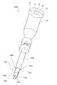
- FIG. 2is a perspective view of an example trocar device according to the present invention.
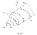
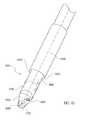
- FIG. 3Ais a perspective view of a first example embodiment of a trocar device according to the present invention.
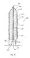
- FIG. 3Bis a side elevational view of the first example embodiment of the trocar device illustrated in FIG. 3A .
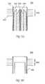
- FIG. 3Cis a cross-sectional schematic view of the first example embodiment of the trocar device illustrated in FIGS. 3A and 3B .
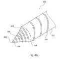
- FIG. 4Ais a perspective view of a second example embodiment of a trocar device according to the present invention.
- FIG. 4Bis a side elevational view of the second example embodiment of the trocar device illustrated in FIG. 4A .
- FIG. 4Cis a cross-sectional schematic view of the second example embodiment of the trocar device illustrated in FIGS. 4A and 4B .
- FIGS. 5A to 5Hillustrate an operation sequence of the trocar device illustrated in FIGS. 4A to 4C .
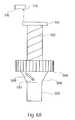
- FIGS. 6A and 6Billustrate a first example embodiment of a torque sensor of the trocar device according to the present invention.
- FIG. 7is a schematic view of a second example embodiment of a torque sensor of the trocar device according to the present invention.
- FIGS. 8A to 8Care schematic views of a first example embodiment of a driving device of the trocar device according to the present invention.
- FIG. 9is a schematic view of a second example embodiment of a driving device of the trocar device according to the present invention.
- FIG. 10is a schematic view of another example trocar device according to the present invention.
- FIG. 11 ais a detailed schematic view of the trocar device illustrated in FIG. 10 .
- FIG. 11 bis a schematic view of a portion of the trocar device illustrated in FIG. 10 .
- FIG. 12is an exploded view of an exemplary trocar device according to the present invention including a dual-shaft driving arrangement.
- FIG. 13is a detailed schematic view of the exemplary trocar device illustrated in FIG. 12 further including a sensing tip and a torque sensor.
- FIGS. 14A to 14Eillustrate an operation sequence of the rotating-cutter trocar device illustrated in FIGS. 10 through 13 .
- FIG. 15is a view of a portion of an example trocar device including a gas sensor for sensing the presence of a gas.
- FIGS. 1-14Einclusive.
- the individual reference charactersdesignate the same or similar elements throughout the several views.
- Electro-mechanical driver device 1may include, for example, a remote power console 2 , which includes a housing 4 having a front panel 3 . Mounted on front panel 3 are a display device 6 and indicators 8 a , 8 b .
- a flexible shaft 5may extend from housing 4 and may be detachably secured thereto via a first coupling 7 .
- the distal end 9 of flexible shaft 5may include a second coupling 6 adapted to detachably secure a surgical instrument or attachment to the distal end 9 of flexible shaft 5 .
- the surgical instrument or attachmentmay be, for example, a trocar device according to the present invention.
- 09/510,927entitled “Electro-mechanical Driver and Remote Surgical Instruments Attachment Having Computer Assisted Control Capabilities”
- U.S. patent application Ser. No. 09/510,931entitled “A Tissue Stapling Attachment for Use with an Electro-mechanical Driver Device”
- U.S. patent application Ser. No. 09/510,932entitled “A Fluid Delivery Mechanism for Use with Anastomosing, Stapling, and Resecting Instruments”
- U.S. patent application Ser. No. 09/510,933entitled “A Fluid Delivery Device for Use with Anastomosing, Stapling, and Resecting Instruments,” each of which is expressly incorporated herein in its entirety by reference thereto.
- the flexible shaft 5includes a tubular outer sheath, which may include a coating or other sealing arrangement to provide a fluid-tight seal between the interior channel thereof and the environment.
- the sheathmay be formed of a tissue-compatible, sterilizable elastomeric material.
- the sheathmay also be formed of a material that is autoclavable. Disposed within the interior channel 150 of the flexible shaft 5 , and extending along the entire length thereof, as shown in FIG.
- 1Amay be a first rotatable drive shaft 152 , a second rotatable drive shaft 154 , a first steering cable 156 , a second steering cable 158 , a third steering cable 160 , a fourth steering cable 162 and/or a data transfer cable 164 , all terminating at the second coupling 6 , at the distal end 9 of the flexible shaft 5 .
- the combined functions of the electro-mechanical driver and control unitsis to provide force and control data, and that one function of the flexible shaft is to communicate that force and control data from the trocar device of the present invention.
- the remote power console 2may include a motor system, which includes one or more motors configured to rotate the first and second rotatable drive shafts and to apply tension or otherwise drive the steering cables to thereby steer the distal end 9 of the flexible shaft 5 .
- a motor systemwhich includes one or more motors configured to rotate the first and second rotatable drive shafts and to apply tension or otherwise drive the steering cables to thereby steer the distal end 9 of the flexible shaft 5 .
- FIG. 1Bthere is seen a top schematic view of a remote control unit (“RCU”) 30 of the electro-mechanical driver device 1 illustrated in FIG. 1 .
- the RCU 30may be, for example, a wired remote control unit, a wireless remote control unit, a hybrid remote control unit, etc.
- the RCU 30may include a number of operable control elements 34 , 36 , which may be, for example, toggle switches, button switches, analog switches, control knobs, potentiometers, etc. It should be understood that although FIG. 1B illustrates two control elements 34 , 36 , any appropriate number of control elements may be provided.
- Trocar device 23may be used in combination with an electro-mechanical driver device, such as that described in U.S. patent application Ser. No. 09/324,452, entitled “Electro-mechanical Driver Device for Use with Anastomosing, Stapling, and Resecting Instruments,” U.S. patent application Ser. No. 09/510,927, entitled “Electro-mechanical Driver and Remote Surgical Instruments Attachment Having Computer Assisted Control Capabilities,” U.S. patent application Ser. No. 09/723,715, entitled “Electro-Mechanical Surgical Device,” U.S. patent application Ser. No.
- Trocar device 23may also be used in combination with a manually-operable driver device.
- Trocar device 23includes a housing 12 , which includes a coupling 14 adapted and configured to detachably couple the trocar device 23 with the second coupling 6 of the flexible shaft 5 of the driver device.
- the couplings 6 and 14may be a quick-connect type fitting, such as a rotary quick-connect type fitting, a bayonet type fitting, etc.
- the couplings 6 and 14may also be a threaded coupling.
- a cavity 16is formed between the housing 12 and the coupling 14 . Disposed within the cavity are a first connector 18 , a second connector 20 and a data connector 22 .
- the first connector 18is adapted and configured to non-rotatably couple to a complementary first connector of the second coupling 6 of the driver device
- the second connector 20is adapted and configured to non-rotatably couple to a complementary second connector of the second coupling 6 of the driver device.
- the complimentary first and second connectors of the second coupling 6are non-rotatably secured to the first drive shaft 152 and the second drive shaft 154 , respectively, of the flexible shaft 5 .
- the motor systemdrives the first connector 18 and the second connector 20 via the first drive shaft 152 and the second drive shaft 154 and the complimentary first and second connectors of the second coupling 6 .
- the data connector 22is adapted and configured to electrically and logically connect to a complementary data connector of the second coupling 6 of the driver device.
- the data connector of the second coupling 6is electrically and logically connected to the control system of the electro-mechanical driver device 1 via the data transfer cable 164 .
- a hollow surgical cannula 24extends distally from the housing 12 and is tapered at its distal end 26 .
- a trocar 28also extends distally from the housing 12 and is contained concentrically within the cannula 24 , as more fully described below.
- the distal end 26 of the cannula 24also includes an aperture, through which the trocar 28 may be extended, as more fully described below.
- FIG. 3Athere is seen a perspective view of a first example embodiment of a trocar device 200 .
- the trocar device 200includes a surgical cannula 202 , an auger 204 disposed concentrically within the cannula 202 and a sensing tip 206 disposed concentrically within the auger 204 .
- FIG. 3Bis a side elevational view of the trocar device 200 .
- the auger 204is provided with cutting threads 208
- the cannula 202is provided with atraumatic, i.e., non-cutting, threads 210 .
- the cutting threads 208 and/or the atraumatic threads 210may be, for example, helical threads, progressive threads, a combination of thread designs, etc.
- FIG. 3Cthere is seen a cross-sectional schematic view of the trocar device 200 illustrated in FIGS. 3A and 3B .
- the sensing tip 206is disposed within a bore 220 of the auger 204 and arranged concentrically with respect to the auger 204 .
- the distal end of the sensing tip 206extends from the distal end of the auger 204 .
- the proximal end of the sensing tip 206is connected to a spring element 212 , which urges the sensing tip distally with respect to the auger 204 .
- a switch 214is provided for detecting proximal movement of the sensing tip 206 , as more fully set forth below.
- the auger 204is disposed within a bore 222 of the cannula 202 and concentrically with respect to the cannula 202 .
- the distal end of the auger 204in its fully extended position, is configured to extend beyond the distal end of the cannula 202 , as illustrated in FIGS. 3A to 3C .
- Each of the cannula 202 and the auger 204is connected with a respective driving element 216 , 218 , the arrangement and operation of which are described below.
- the auger 204is also provided with a torque sensor, which is further described below.
- FIG. 4Athere is seen a perspective view of a second example embodiment of a trocar device 300 according to the present invention.
- the trocar device 300includes a surgical cannula 302 having atraumatic threads 310 , an external auger 304 having cutting threads 314 , an internal auger 306 having cutting threads 316 and a sensing tip 308 .
- FIG. 4Bis a side elevational view of the trocar device 300 illustrated in FIG. 4A .
- the atraumatic threads 310 , the cutting threads 314 and/or the cutting threads 316may be, for example, helical threads, progressive threads, a combination of thread designs, etc.
- FIG. 4Cthere is seen a cross-sectional schematic view of the trocar device 300 illustrated in FIGS. 4A and 4B .
- the sensing tip 308is disposed within a bore 318 of the internal auger 306 and is arranged concentrically with respect to the internal auger 306 .
- the internal auger 306is disposed within a bore 320 of the external auger 304 and is arranged concentrically with respect to the external auger 304 .
- the external auger 304is disposed within a bore 322 of the cannula 302 and is arranged concentrically with respect to the cannula 302 .
- the distal end of the sensing tip 308in its fully extended position, extends from the distal end of the internal auger 306 .
- the proximal end of the sensing tip 308is connected to a spring element 326 , which urges the sensing tip 308 distally with respect to the internal auger 306 .
- a switch 328is provided for detecting the proximal movement of the sensing tip 308 .
- the distal end of the internal auger 306extends from the distal end of the external auger 304 , and, in its fully extended position, the distal end of the external auger 304 extends from the distal end of the cannula 302 . It should be appreciated that FIG.
- FIG. 4Cillustrates the internal auger 306 and the external auger 304 in their fully extended positions.
- Each of the cannula 302 , the external auger 304 and the internal auger 306is connected to a respective driving element 330 , 332 , 334 .
- the internal auger 306is provided with a torque sensor 336
- the external auger 304is provided with a torque sensor 338 , both of which are described below.
- FIGS. 3C and 4Cillustrate the trocar device 200 , 300 schematically and that the driving elements 216 , 218 of the trocar device 200 and the driving elements 330 , 332 , 334 of the trocar device 300 may be provided in the housing 12 of the trocar device 200 , 300 , in the electro-mechanical driver device 1 or a combination thereof. Similarly, the torque sensors 224 , 336 , 338 may be provided within the housing 12 of the trocar device 200 , 300 , in the electro-mechanical driver device 1 or a combination thereof.
- the driving elements 216 , 218 , 330 , 332 , 334 and the torque sensors 224 , 336 , 338are operated by the operator via the control system of the electro-mechanical driver device 1 and that the output of the torque sensors 224 , 336 , 338 is used by the control system of the electro-mechanical driver device 1 to control the operation of the trocar device 200 , 300 , as more fully described below.
- FIGS. 5A to 5Hthere is seen an operational sequence of the trocar device 300 illustrated in FIGS. 4A to 4C .
- the trocar device 300 or portions thereofmay be sterilized sometime prior to use.
- FIG. 5Aillustrates the trocar device 300 prior to contacting the surface 402 of tissue 400 (e.g., human or animal).
- tissue 400e.g., human or animal.
- the internal auger 306 and the external auger 304have been substantially retracted into the cannula 302 .
- At least a portion of the sensing tip 308is arranged to extend from the distal end of the cannula 302 .
- a distal end portion of the internal auger 306may also be configured to extend from the distal end of the cannula 302 when the trocar device 300 is in the condition prior to contacting the surface 402 of the tissue 400 as illustrated in FIG. 5A .
- the trocar device 300is located at the intended point of incision and pressed against the surface 402 of the tissue 400 .
- the sensing tip 308is caused to be displaced in the direction of the arrow 404 by the pressing of the trocar device 300 against the surface 402 of the tissue 400 .
- the displacement of the sensing tip 308causes the state of the switch 328 to change from ON to OFF or vice versa depending on whether switch 328 is configured as a normally-closed or normally-open switch.
- the change of state of the switch 328signals the control system of the electro-mechanical driver device 1 that the trocar device 300 is in position against the surface 402 of the tissue 400 .
- the control systemdetermines that the trocar device 300 is in position against the surface 402 of tissue 400 , in accordance with the state of switch 328 , the control system prevents the operation of the driving elements 330 , 332 , 334 . In addition, the control system does not activate the driving elements 330 , 332 , 334 until the appropriate control element 34 , 36 of RCU 30 has been activated by the operator. Thus, the driving elements 330 , 332 , 334 are not activated until the trocar device 300 is in position and the appropriate control element 34 , 36 has been activated.
- the control system of the electro-mechanical driver device 1activates the driving element 330 to rotate the cannula 302 , the driving element 332 to rotate the external auger 304 and the driving element 334 to rotate the internal auger 306 .
- the driving elements 332 , 334advance or extend the respective auger 304 , 306 in accordance with the rotation and thread pitch thereof.
- the torque sensors 336 , 338respectively output a signal to the control system of the electro-mechanical driver device 1 in accordance with the torque required to continue the rotation and advancement of the internal auger 306 and the external auger 304 .
- the cutting threads 316 of the internal auger 306 and the cutting threads 314 of the external auger 304are configured to cut into the tissue 400 as well as to draw the tissue 400 proximally there along.
- the control system of the electro-mechanical driver device 1continues the rotation of the internal auger 306 , the external auger 304 and the cannula 302 and the extension of the internal auger 306 and the external auger 304 until it is determined that the internal auger 306 has traversed the tissue 400 .
- This determinationis made in accordance with the output of the torque sensor 336 . That is, the torque required to continue the rotation and extension of the internal auger 306 will decrease at the time that the distal end of the internal auger 306 has fully traversed the tissue 400 .
- the trocar device 300is illustrated in FIG. 5D in the condition and position where the internal auger 306 has fully traversed the tissue 400 .
- the control system of the electro-mechanical driver device 1continues the rotation of the external auger 304 and the cannula 302 and the extension of the external auger 304 but causes the retraction of the internal auger 306 into the bore 320 of the external auger 304 .
- the retraction of the internal auger 306may be performed with or without the rotation of the internal auger 306 in accordance with the design and arrangement of the driving element 334 .
- the control system of the electro-mechanical driver device 1causes the continued retraction of the internal auger 306 until it has reached its fully retracted position in the bore 320 while simultaneously continuing the rotation of the external auger 304 and cannula 302 and the extension of the external auger 304 .
- the atraumatic threads 310 of the cannula 302draw the cannula 302 into the tissue 400 .
- the torque sensor 338 of the external auger 304outputs a signal to the control system of the electro-mechanical driver device 1 during this operation.
- the torque necessary to continue the rotation of the external auger 304will decrease.
- This conditionas determined by control system of the electro-mechanical driver device 1 in accordance with the output from the torque sensor 338 , causes the control system to retract the external auger 304 relative to the cannula while continuing to rotate the cannula 302 .
- FIG. 5Eillustrates the trocar device 300 in the position in which the external auger 304 has reached its maximum extension from the cannula 302 .
- the control system of the electro-mechanical driver device 1causes the external auger 304 to retract relative to the cannula 302 while continuing the rotation of the cannula 302 to draw the cannula 302 into the incision by the atraumatic threads 310 thereof.
- the retraction of the external auger 304may be performed with or without rotation thereof in accordance with the design and configuration of the driving element 332 .
- the continued rotation of the cannula 302draws the cannula 302 into the tissue 400 until the distal end of the cannula 302 has at least traversed the tissue 400 .
- the cannula 302may be further rotated to draw the cannula 302 an additional length into the cavity 406 as illustrated in FIG. 5G .
- the driving element 330is deactivated, thereby stopping the rotation, and the advancement, of the cannula 302 .
- the internal auger 306 and the external auger 304are subsequently withdrawn from the cannula 302 to thereby provide access to the cavity 406 by an instrument 408 via the cannula 302 as illustrated in FIG. 5H .
- a sealmay be provided, for example, at the proximal end of the cannula 302 , to provide a fluid-tight and/or gas-tight seal between the cavity 406 and the environment.
- the cannula 302may be removed from the housing 12 , to thereby provide access to the cavity 406 via the cannula 302 .
- the housing 12may be provided with a port to provide access to the cavity 406 via the cannula 302 .
- control system of the electro-mechanical driver device 1may be controlled by, for example, a control element 34 , 36 of RCU 30 , to rotate the cannula 302 to cause the retraction of the cannula 302 from the tissue 400 .
- Torque sensor 500is illustrated in FIGS. 6A and 6B as being configured to measure the torque necessary to drive the shaft 502 .
- the shaft 502may correspond to, for example, the auger 204 of the trocar device 200 , the internal auger 306 of the trocar device 300 , the external auger 304 of the trocar device 300 , etc.
- the shaft 502includes a gear 504 secured thereto that is driven by the driving element corresponding to the shaft 502 .
- a spring element 512is provided on one side of gear 504 and secured to the shaft 502 by cap element 514 .
- the side of gear 504 opposite to spring element 512is provided with a collar 504 , which is non-rotatably secured to the gear 504 .
- the collar 506is provided with a slot 508
- the shaft 502is provided with a pin 510 slidably disposed in the slot 508 .
- the torque sensor 500further includes a switch element 516 , which includes an actuator 518 .
- Switch 516may be a normally-open switch or a normally-closed switch.
- FIG. 6Aillustrates the shaft 502 and torque sensor 500 in a low torque condition, in which the spring element 512 urges the cap element 514 against the actuator 518 of switch element 516 .
- FIG. 6Billustrates the condition that the torque requirement for driving shaft 502 has exceeded the predefined threshold.
- FIG. 7there is seen a schematic view of a second example embodiment of a torque sensor 600 of the trocar device according to the present invention.
- the torque sensor 600is configured to measure the torque necessary to drive a shaft 602 , which may correspond to, for example, the auger 204 of the trocar device 200 , the internal auger 306 of the trocar device 300 , the external auger 304 of the trocar device, 300 , etc.
- the torque sensor 600includes a first disk 604 secured to the shaft 602 at a first location along the length thereof and a second element 616 secured to the shaft 602 at a second location thereof.
- the second element 616includes a flange 606 . As illustrated in FIG.
- the first locationis spaced from the second location at a distance d.
- Each of the first disk 604 and the flange 606includes a series of radially-spaced apertures having predefined areas. In a zero-torque condition of the shaft 602 , the apertures of the first disk 604 are aligned with the apertures of the flange 606 .
- a light source 608which is powered by line 610
- a light sensor 612which outputs a signal via line 614 , are arranged on opposite sides of the first disk 604 and the flange 606 .
- the light sensor 612may be configured, for example, to output a signal in accordance with an intensity of light received thereby from light source 608 .
- the alignment of the apertures of first disk 604 relative to the apertures of flange 606is shifted.
- the area of the resultant aperturedecreases in accordance with an increasing torque requirement. This area change is measurable by the light sensor 612 in accordance with the resultant change of light intensity being transmitting by the light source 608 to the light sensor 612 .
- FIGS. 8A to 8Cillustrate schematically a first example embodiment of a driving device 700 of the trocar device according to the present invention.
- the driving device 700is configured to perform the rotation of and the extension and retraction of the several shafts 702 , 704 , 706 .
- a first shaft 706is disposed concentrically and rotatably within a bore 705 of a second shaft 704
- the second shaft 704is disposed concentrically and rotatably within a bore 703 of a third shaft 702 .
- the first shaft 706may correspond to the internal auger 306 of the trocar device 300
- the second shaft 704may correspond to the external auger 304 of the trocar device 300
- the third shaft 702may correspond to the cannula 302 of the trocar device 300
- a fourth shaft 708may be disposed within a bore 707 of the first shaft 706 .
- the fourth shaft 708may correspond to the sensing tip 308 of the trocar device 300 . It should be appreciated that any appropriate number of shafts may be provided in the driving device 700 and that the number of shafts illustrated in FIGS. 8A to 8C is merely intended to be exemplary.
- a first gear 714is non-rotatably provided at the proximal end of the first shaft 706
- a second gear 712is non-rotatably provided at the proximal end of the second shaft 704
- a third gear 710is non-rotatably provided at the proximal end of the third shaft 702 .
- the driving device 700further includes a rotatable and axially displaceable driveshaft 716 .
- the driveshaft 716includes a first gear 730 ; a second gear 724 and a third gear 718 , each of which is non-rotatably secured to the driveshaft.
- Each of the first gear 730 , the second gear 724 and the third gear 718is rotatable and axially displaceable in accordance with the rotation of the driveshaft 716 and the axial displacement thereof. It should be appreciated that the first gear 730 and the first gear 714 are engageable so that the rotation of the driveshaft 716 causes the rotation of the first shaft 706 .
- the second gear 724is engageable with the second gear 712 so that the rotation of the driveshaft 716 causes rotation of the second shaft 704
- the third gear 718is engageable with the third gear 710 so that rotation of the driveshaft 716 causes rotation of the third shaft 702 .
- the gear ratioswill determine the relative rotation between the first shaft 706 , the second shaft 704 and the third shaft 702 . As illustrated in FIGS.
- the gear ratios between the first gear pair 714 , 730 , the second gear pair 712 , 724 and the third gear pair 710 , 718may be the same so that the first shaft 706 , the second shaft 704 and the third shaft 702 rotate synchronously in accordance with the rotation of the driveshaft 716 .
- the proximal end of the driveshaft 716is provided with a gear 736 , which is drivable by a driveshaft 738 , the rotation of which effects the rotation of the driveshaft 716 .
- the gear 736may be, for example, a worm gear, a spur gear, etc.
- the proximal end of the driveshaft 716is also provided with a rack 740 via mount 742 .
- the driveshaft 716is rotatably secured to the mount 742 and axially displaceable therewith.
- a pinion 744is provided for axially displacing the mount 742 , and therefore the driveshaft 716 and gears 718 , 724 , 730 , via the rack 740 .
- the first gear 730includes a distal shoulder 732 and a proximal shoulder 734 that engage the distal and proximal surfaces of the first gear 714 to effect axial displacement of the first shaft 706 as more fully described below.
- the second gear 724includes a distal shoulder 726 and a proximal shoulder 728 that engage the distal and proximal surfaces of second gear 712 to effect the axial displacement of the second shaft of 704 as more fully described below.
- the third gear 718includes a distal shoulder 720 and a proximal shoulder 722 that engage the distal and proximal surfaces of the third gear 710 to effect the axial displacement of the third shaft 702 and/or to act as positive stops for driving device 700 .
- the height of the first gear 730i.e., the distance between the distal shoulder 732 and the proximal shoulder 734 , is substantially equal to the height of the first gear 714 . That is, there is substantially zero axial clearance between the shoulders 732 , 734 and the distal and proximal surfaces of first gear 714 .
- the height of the second gear 724i.e., the distance between the distal shoulder 726 and the proximal shoulder 728 , is elongated as compared to the height of the first gear 730
- the height of the third gear 718i.e., the distance between the distal shoulder 720 and the proximal shoulder 722 , is elongated as compared to the height of the first gear 730 and the height of the second gear 724 .
- the heights of the gears 730 , 724 , 718define the stroke of the respective shaft 706 , 704 , 702 .
- FIG. 8Aillustrates the first shaft 706 and the second shaft 704 in their fully extended positions.
- the distance between the first gear 714 and the second gear 712is represented in FIG. 8A as d 1
- the distance between the second gear 712 and the third gear 710is represented in FIG. 8B as d 2
- the distance between the pinion 744 and the distal end of the driveshaft 716is represented as D 0 . It should be understood that these distances are only referred to herein for clarity purposes and to illustrate the relative displacement of the elements of the driving device 700 as more fully set forth below.
- FIG. 8Bthere is seen a schematic view of the driving device 700 in which the pinion 744 has effected an axial displacement of the driveshaft 716 by a distance ⁇ D 1 so that the distance between the pinion 744 and the distal end of the driveshaft 716 is represented by D 1 .
- the first shaft 706has been displaced to its fully retracted position relative to the second shaft 704 . That is, the axial displacement of the first gear 730 , in accordance with the operation of pinion 744 , causes axial displacement of the first gear 714 by the interaction of the distal shoulder 732 of the first gear 730 with the distal surface of the first gear 714 .
- the height of the second gear 724 and the height of the third gear 718permit the second shaft 704 and the third shaft 702 to remain stationary in the axial direction during this stroke of the first shaft 706 .
- the distance between the first gear 714 and the second gear 712has increased from d 1 to d 1 ′ while the distance between the second gear 712 and the third gear 710 has remained substantially at d 2 .
- the value of d 1 ′is substantially equal to the sum of the values d 1 and ⁇ D 1 and that the axial displacement of the first shaft 706 relative to the second shaft 704 is substantially equal to the value ⁇ D 1 .
- FIG. 8Cthere is seen a schematic view of the driving device 700 in which the pinion 744 has effected a further axial displacement of the driveshaft 716 by an additional distance of ⁇ D 2 , so that the distance between the pinion 744 and the distal end of the drive shaft 716 is represented by D 2 .
- the first shaft 706remains in its fully retracted position relative to the second shaft 704 , and the second shaft 704 has been displaced to its fully retracted position relative to the third shaft 702 .
- the axial displacement of the first gear 730in accordance with the operation of the pinion 744 , causes further axial displacement of the first gear 714 by the interaction of the distal shoulder 732 of the first gear 730 with the distal surface of the first gear 714 .
- the axial displacement of second gear 724in accordance with the operation of the pinion 744 , causes axial displacement of the second gear 712 by the interaction of the distal shoulder 726 of the second gear 724 with the distal surface of the second gear 710 .
- the height of the third gear 718permits the third shaft 702 to remain stationary in the axial direction during this stroke of the first shaft 706 and the second shaft 704 .
- the height of the third gear 718may define the positive steps for the axial displacement of the drive shaft 716 .
- the distance between the first gear 714 and the second gear 712has remained substantially equal to d 1 ′ while the distance between the second gear 712 and the third gear 710 has increased from d 2 to d 2 ′.
- the value of d 2 ′is substantially equal to the sum of the values of d 2 and ⁇ D 2 and that the axial displacement of the second shaft 704 relative to the third shaft 702 is substantially equal to the value of ⁇ D 2 .
- the first shaft 706is axial displaced relative to the third shaft 702 by a distance substantially equal to the value of ⁇ D 2 . That is, the total axial displacement of the first shaft 706 relative to the third shaft 702 between the position illustrated in FIG. 8A and the position illustrated in FIG. 8C is substantially equal to the sum of the values of ⁇ D 1 and ⁇ D 2 .
- FIGS. 8A to 8Cillustrated the retraction of the first shaft 706 and the second shaft 704 in sequence
- the first shaft 706 and second shaft 704are extendable by reversing the sequence, i.e., operating the pinion 744 to extend the drive shaft 716 .
- the heights of the gears 730 , 724 , 718define the strokes of the first shaft 706 and the second shaft 704 .
- a rack 740 and pinion 744are described above for axially displacing the drive shaft 716 , any device suitable for effecting axial displacement, such as, for example, a solenoid, a linear motor, alternative gearing arrangements, etc., may be used.
- the first gear pair 714 , 730 , the second gear pair 712 , 724 and/or the third gear pair 710 , 718may be, for example, spur gears, helical gears, etc.
- FIG. 9there is seen a schematic view of a second example embodiment of a driving device 800 of the trocar device according to the present invention.
- the driving device 800is configured to rotate a first shaft 806 , which is concentrically and rotatably disposed in a bore 805 of a second shaft 804 , to rotate the second shaft 804 , which is concentrically and rotatably disposed in a bore 803 of a third shaft 802 and to rotate the third shaft 802 .
- the driving device 800is also configured to axially displace the first shaft 806 and the second shaft 804 .
- a fourth shaft 808is illustrated in FIG. 9 as being concentrically disposed within a bore 807 of the first shaft 806 . It should be appreciated that the driving device 800 may be configured to rotate any number of shafts and to axially displace any one or more of such shafts.
- a first gear 814is non-rotatably provided at the proximal end of the first shaft 806
- a second gear 812is provided at the proximal end of the second shaft 804
- a third gear 810is provided at the proximal end of the third shaft 802 .
- Each of the first gear 814 , the second gear 812 and the third gear 810is arranged and configured to be rotated in accordance with the rotation of a drive shaft 816 .
- the gears 814 , 812 , 810 and drive shaft 816may be configured, for example, as spur gears, helical gears, etc.
- the drive shaft 816may be rotated by a driving element 818 , which may include, for example, a motor.
- the driving device 800further includes a first linear actuator 850 configured to axially displace the first shaft 806 .
- the first linear actuator 850includes a rack 820 , a distal shoulder 826 and a proximal shoulder 824 .
- the rack 820is engageable with a pinion 828 , and the rack 820 , distal shoulder 826 and proximal shoulder 824 are displaceable as a unit in accordance with the operation of the pinion 828 .
- the first gear 814is disposed between the distal shoulder 826 and the proximal shoulder 824 to effect axial displacement thereof.
- the rack 820 , the distal shoulder 826 and the proximal shoulder 824are slidably disposed on stem 822 .
- the second linear actuator 860includes a rack 830 , a distal shoulder 836 and a proximal shoulder 834 slidably disposed and displaceable as a unit on stem 832 .
- the displacement of the rack 830 , the distal shoulder 836 and the proximal shoulder 834 by the pinion 838effects the displacement of the second shaft 804 by the interaction of the distal shoulder 836 and the proximal shoulder 834 with the second gear 812 .
- a trocar device 1000includes a housing 12 with a coupling 14 adapted and configured to detachably couple the trocar device 1000 with, for example, the second coupling 6 of the flexible shaft 5 of the driver device.
- the coupling 14 of the trocar device 1000may be a quick-connect type fitting, such as, for example, a rotary quick-connect type fitting, a bayonet type fitting, etc.
- the couplings 6 and 14may also be a threaded coupling.
- a cavity 16is formed between the housing 12 and the coupling 14 .
- a first connector 18Disposed within the cavity are a first connector 18 , a second connector 20 and a data connector 22 .
- the first connector 18is adapted and configured to non-rotatably couple to the complementary first connector of the second coupling 6 of the driver device
- the second connector 20is adapted and configured to non-rotatably couple to the complementary second connector of the second coupling 6 of the driver device.
- the motor systemdrives (e.g., rotates) the first connector 18 and the second connector 20 via the first drive shaft 152 and the second drive shaft 154 and the complimentary first and second connectors of the second coupling 6 .
- the data connector 22is adapted and configured to electrically and logically connect to the complementary data connector of the second coupling 6 of the driver device, which is electrically and logically connected to the control system of the electro-mechanical driver device 1 via the data transfer cable 164 .
- a cutting arrangement 1010extends distally from the housing 12 .
- the cutting arrangement 1010includes a housing 1012 , a blade housing portion 1130 connected to the housing 1012 , a cutting blade 1120 , and a pin 1140 .
- the blade housing portion 1130has a tapered distal end 1150 for easy insertion into an incision to be formed.
- the cutting blade 1120may be rotatably connected, for example, to a tapered distal end 1150 of the blade housing portion 1130 via the pin 1140 .
- the cutting blade 1120may have a generally circular profile and/or a generally disk shape, for example, and may include one or a number of sharp edges and/or cutting teeth for cutting tissue (e.g., human or animal tissue).
- a surgical cannula 1390is also provided for insertion into tissue.
- the cannula 1390surrounds the cutting arrangement 1010 and may be configured to be moveable and removeable (mechanically or manually) relative to the cutting arrangement 1010 .
- the cannula 1390may be tapered at a distal end 1392 .
- the distal end 1011 of the cutting arrangement 1010extends through a bore 1393 of the cannula and beyond the distal end 1392 of the cannula 1390 .
- the trocar device 1000includes a first (e.g., rotatable) driving element 1110 , connected to the first connector 18 , a second (e.g., rotatable) driving element 1115 connected to the second connector 20 , and a data line 1112 connected to the data connector 22 .
- a first driving element 1110is configured to drive the cutting blade 1120 of the cutting arrangement 1010 .
- the second driving element 1115is configured to extend and/or retract the cannula 1390 with respect to the cutting arrangement 1010 .
- the second driving element 1115slidably extends and/or retracts the cannula 1390 .
- the second driving element 1115rotatably extends and/or retracts the cannula 1390 , such as described above in connection with cannula 202 .
- the cannula 1390may be extended and removed from the trocar device manually. Additionally, the cannula 1390 may include atraumatic threads as described above in connection with cannula 202 .
- the trocar device 1000may also include a memory device 1113 coupled to data line 1112 .
- the memory device 1113may store data relating to the operation and/or identification of the trocar device.
- the datamay include, for example, an indication of a device type, a serial number, calibration information, usage information (e.g., an indication of a number of times the device has been utilized or, for example, an indication that the device has been utilized at all), etc.
- a controller in an electro-mechanical driverreads and utilizes the data stored in the memory device.
- the controllermay, for example, choose a control program with which to control the trocar or components thereof (e.g., one or more of the driver(s)/driving element(s)) as a function of the device type.
- the controllermay also calibrate the trocar device 1000 and/or portions of the system coupled to the trocar device, based on the calibration information.
- the stored serial numbermay be read by the controller and used for tracking, billing and inventory purposes.
- the controllermay limit the number of times the trocar device 1000 is utilized based on data in the memory.
- the controllermay also update information in the memory device 1113 .
- the trocar device 1000is for single-use only. Thus, once utilized, the controller stores in the memory device 1113 , an indication that the trocar device 1000 has been utilized. If an attempt is made to use the trocar device 1000 again, the controller reads the information in the memory device 1113 , determines that the trocar device 1000 has already been used, and displays an error message to the operator.
- the memory device 1113may also store, for example, a control program or portion of a control program, which the controller may read and utilize to control the trocar.
- the memory device 1113may be disposed at alternate locations, such as, for example, within the cutting arrangement 1010 .
- the memory devicemay be used with various types of trocar devices, such as, for example, a trocar with an auger and/or a trocar with a cutting blade having a generally circular profile.
- Dual-shaft driving arrangement 1210is at least partially disposed within the cutting arrangement 1010 .
- Dual-shaft driving arrangement 1210includes a main shaft 1220 having a proximal end 1230 coupled to and driven by the first connector 18 (not shown) and a distal end 1240 non-rotatably coupled to a first gear element 1250 , the first gear element 1250 being non-rotatably coupled to a first drive shaft 1260 .
- a second gear element 1270engages the first gear element 1250 and is non-rotatably coupled to a second drive shaft 1280 . It will be appreciated that the engagement of the first gear element 1250 and the second gear element 1270 allows the second drive shaft 1280 to be rotatably driven in a second angular direction 1405 opposite to the rotation of the first drive shaft 1260 in a first angular direction 1400 .
- First drive shaft 1260 and second drive shaft 1280are each received by first bearings 1290 and second bearings 1300 , first bearings 1290 and second bearings 1300 being rotatably received by a securing device 1305 .
- a distal end 1310 of first drive shaft 1260 and a distal end 1320 of second drive shaft 1280are non-rotatably connected to respective capstans 1330 , between which a proximal end 1340 of the cutting blade 1120 is frictionally engaged, the cutting blade 1120 being rotatably connected to the blade housing portion 1130 by pin 1140 .
- Capstans 1330may be made of any material suitable for frictionally engaging the proximal end 1340 of the cutting blade 1120 , such as, for example, silicon rubber.
- FIG. 12illustrates the first driving element 1110 having the dual-shaft driving arrangement 1210
- the present inventionis intended to include other conventional driving arrangements, which may be employed to drive the cutting blade 1120 in lieu of or in addition to the dual-shaft driving arrangement 1210 .
- a trocar device 1000 of the type illustrated in FIG. 12further including a sensing tip 1350 .
- the sensing tip 1350is slidably disposed within a bore 1355 of the tapered distal end 1150 of the blade housing portion 1130 and arranged, e.g., substantially parallel to a longitudinal axis 1360 of the rotating cutter trocar device 1000 .
- a proximal end of the sensing tip 1365is connected to a spring element 1370 , which urges the sensing tip distally with respect to the cutting blade 1120 .
- a switch 1375 electrically and logically connected to the data line 1112is provided for detecting proximal movement of the sensing tip 1365 , as more fully set forth below.
- a surgeonmay insufflate the abdominal cavity with CO 2 gas to separate the abdominal wall from the viscera.
- a trocar device with a CO 2 gas sensormay detect the presence of the CO 2 gas, the detection of which indicates the penetration of the trocar device into the abdominal cavity.
- the electro-mechanical driver device 1may, for example, cease operation of the cutting blade 1120 .
- FIG. 15there is seen an example embodiment of a cutting arrangement 1010 of a trocar device 1000 having a gas sensor 1410 for detecting the presence of a gas, such as, for example carbon dioxide (CO 2 ).
- Gas sensor 1410may be disposed, for example, at the tapered distal end 1150 of the blade housing portion 1130 of the cutting arrangement 1010 .
- Gas sensor 1410is electrically connected to the data line 1112 for communicating sensed gas data to the electro-mechanical driver device 1 via the data connector 22 .
- gas sensor 1410may be disposed at alternate locations, such as, for example, within or on the blade housing portion 1130 of the cutting arrangement 1010 .
- gas sensor 1410may be used with various types of trocar devices, such as, for example, a trocar with an auger and/or a trocar with a cutting blade having a generally circular profile.
- the cutting arrangement 1010may be provided with a torque sensor 1380 of a similar type as that described above with respect to the trocar device 200 , 300 .
- the torque sensor 1380is electrically and logically connected to the data line 1112 .
- the output of the torque sensor 1380is used by the control system of the electro-mechanical driver device 1 to control the operation of the trocar device 1000 , as more fully described below.
- FIGS. 14A to 14Hthere is seen on example operational sequence of the trocar device 1000 illustrated in FIGS. 10-13 .
- FIG. 14Aillustrates the trocar device 1000 prior to contacting the surface 402 of tissue 400 .
- the trocar device 1000 or portions thereofmay be sterilized some time prior to use.
- the cannula 1390is extended beyond the cutting arrangement 1010 .
- At least a portion of the sensing tip 1350is arranged to extend beyond the distal end 1392 of the cannula 1390 .
- a distal end 1345 of the cutting blade 1120 of the rotating cutter arrangement 1010may also be configured to extend beyond the distal end 1392 of the cannula 1390 when the trocar device 1000 is in the condition prior to contacting the surface 402 of the tissue 400 as illustrated in FIG. 14A .
- the trocar device 1000is located at the intended point of incision and pressed against the surface 402 of the tissue 400 .
- the sensing tip 1350is caused to be displaced in the direction of the arrow 1395 and toward spring element 1370 by the pressing of the trocar device 1000 against the surface 402 of the tissue 400 .
- the displacement of the sensing tip 1350causes the state of the switch 1375 to change from ON to OFF or vice versa depending on whether switch 1375 is configured as a normally-closed or normally-open switch.
- the change of state of the switch 1375signals the control system of the electro-mechanical driver device 1 that the trocar device 1000 is in position against the surface 402 of the tissue 400 .
- the control systemprevents the operation of the first driving element 1110 and the second driving element 1115 (not shown). In addition, the control system does not activate the first driving element 1110 and the second driving element 1115 until the appropriate control element 34 , 36 of RCU 30 has been activated by the operator. Thus, in this example embodiment of the present invention, the first driving element 1110 and the second driving element 1115 are not activated until the trocar device 1000 is in position and the appropriate control element 34 , 36 has been activated.
- the control system of the electro-mechanical driver device 1activates the first driving element 1110 to rotate the cutting blade 1120 .
- the electro-mechanical driver device 1drives the first connector 18 , which, in turn, rotationally drives the main shaft 1220 , the first drive shaft 1260 , and the first gear element 1250 in a first angular direction 1400 .
- the rotation of first gear element 1250causes engaged second gear element 1270 to rotate in an opposite second angular direction 1405 , which, in turn, also causes second drive shaft 1260 to rotate in the second angular direction 1405 (i.e., first drive shaft 1260 and second drive shaft 1280 rotate in opposite directions).
- the counter-rotation of the first drive shaft 1260 and second drive shaft 1280cause the cutting blade 1120 to rotate via the capstans 1330 , which frictionally engage the proximal end 1340 of the cutting blade 1120 .
- the torque sensor 1380outputs a signal to the control system of the electro-mechanical driver device 1 in accordance with the torque required to continue the rotation of the cutting blade 1120 . It should be appreciated that the cutting blade 1120 is configured to cut into the tissue 400 .
- the control system of the electro-mechanical driver device 1continues the rotation of the cutting blade 1120 until it is determined that the tapered distal end 1150 of the blade housing portion 1130 has traversed the tissue 400 .
- This determinationis made in accordance with the output of the torque sensor 1380 . That is, the torque required to continue the rotation and extension of the cutting blade 1120 will decrease at the time that the tapered distal end 1150 of the blade housing portion 1130 has traversed the tissue 400 .
- the trocar device 1000is illustrated in FIG. 14C in the condition and position where the tapered distal end 1150 of the blade housing portion 1130 has traversed the tissue 400 .
- the control system of the electro-mechanical driver device 1ceases rotation of the cutting blade 1120 and activates the second driving element 1115 via the second connector 20 to slide or rotate the cannula 1390 , so that the cannula is displaced distally with respect to the cutting arrangement 1010 , thereby drawing the cannula 1390 into the tissue 400 .
- the cannula 1390is drawn into the tissue 400 until the distal end 1392 of the cannula 1390 has at least traversed the tissue 400 , as shown in FIG. 14D .
- the cannula 1390may be further extended an additional length into the cavity 406 .
- the second driving element 1115is deactivated, thereby stopping the further advancement of the cannula 1390 into the tissue 400 .
- the cutting arrangement 1010is subsequently withdrawn from the cannula 1390 to thereby provide access to the cavity 406 by an instrument 408 via the cannula 1390 as illustrated in FIG. 14E .
- a sealmay be provided, for example, at the proximal end 1395 of the cannula 1390 , to provide a fluid-tight and/or gas-tight seal between the cavity 406 and the environment.
- the cannula 1390may be removed from the housing 12 , to thereby provide access to the cavity 406 via the cannula 1390 .
- the housing 12may be provided with a port to provide access to the cavity 406 via the cannula 1390 .
- the trocarmay include a reciprocating cutter (and corresponding driver(s) and gears), instead of a rotating cutter.
Landscapes
- Health & Medical Sciences (AREA)
- Surgery (AREA)
- Life Sciences & Earth Sciences (AREA)
- Biomedical Technology (AREA)
- Nuclear Medicine, Radiotherapy & Molecular Imaging (AREA)
- Engineering & Computer Science (AREA)
- Pathology (AREA)
- Heart & Thoracic Surgery (AREA)
- Medical Informatics (AREA)
- Molecular Biology (AREA)
- Animal Behavior & Ethology (AREA)
- General Health & Medical Sciences (AREA)
- Public Health (AREA)
- Veterinary Medicine (AREA)
- Surgical Instruments (AREA)
Abstract
Description
Claims (4)
Priority Applications (4)
| Application Number | Priority Date | Filing Date | Title |
|---|---|---|---|
| US10/098,217US7905897B2 (en) | 2001-03-14 | 2002-03-14 | Trocar device |
| US13/031,632US9192410B2 (en) | 2001-03-14 | 2011-02-22 | Trocar device |
| US13/031,669US9055971B2 (en) | 2001-03-14 | 2011-02-22 | Trocar device |
| US13/031,643US9186177B2 (en) | 2001-03-14 | 2011-02-22 | Trocar device |
Applications Claiming Priority (3)
| Application Number | Priority Date | Filing Date | Title |
|---|---|---|---|
| US27586901P | 2001-03-14 | 2001-03-14 | |
| US33754401P | 2001-12-04 | 2001-12-04 | |
| US10/098,217US7905897B2 (en) | 2001-03-14 | 2002-03-14 | Trocar device |
Related Child Applications (3)
| Application Number | Title | Priority Date | Filing Date |
|---|---|---|---|
| US13/031,632DivisionUS9192410B2 (en) | 2001-03-14 | 2011-02-22 | Trocar device |
| US13/031,643DivisionUS9186177B2 (en) | 2001-03-14 | 2011-02-22 | Trocar device |
| US13/031,669DivisionUS9055971B2 (en) | 2001-03-14 | 2011-02-22 | Trocar device |
Publications (2)
| Publication Number | Publication Date |
|---|---|
| US20020198554A1 US20020198554A1 (en) | 2002-12-26 |
| US7905897B2true US7905897B2 (en) | 2011-03-15 |
Family
ID=26794431
Family Applications (2)
| Application Number | Title | Priority Date | Filing Date |
|---|---|---|---|
| US10/098,217Expired - LifetimeUS7905897B2 (en) | 2001-03-14 | 2002-03-14 | Trocar device |
| US13/031,669Expired - LifetimeUS9055971B2 (en) | 2001-03-14 | 2011-02-22 | Trocar device |
Family Applications After (1)
| Application Number | Title | Priority Date | Filing Date |
|---|---|---|---|
| US13/031,669Expired - LifetimeUS9055971B2 (en) | 2001-03-14 | 2011-02-22 | Trocar device |
Country Status (1)
| Country | Link |
|---|---|
| US (2) | US7905897B2 (en) |
Cited By (169)
| Publication number | Priority date | Publication date | Assignee | Title |
|---|---|---|---|---|
| US20110144681A1 (en)* | 2001-03-14 | 2011-06-16 | Tyco Healthcare Group Lp | Trocar device |
| US8505799B2 (en) | 2005-06-03 | 2013-08-13 | Covidien Lp | Battery powered surgical instrument |
| US20130274782A1 (en)* | 2012-04-16 | 2013-10-17 | Pacesetter, Inc. | Apparatus and method for pericardial access |
| US8657177B2 (en) | 2011-10-25 | 2014-02-25 | Covidien Lp | Surgical apparatus and method for endoscopic surgery |
| US8851355B2 (en) | 2011-10-25 | 2014-10-07 | Covidien Lp | Apparatus for endoscopic procedures |
| US8888762B2 (en) | 2004-07-30 | 2014-11-18 | Covidien Lp | Flexible shaft extender and method of using same |
| US8899462B2 (en) | 2011-10-25 | 2014-12-02 | Covidien Lp | Apparatus for endoscopic procedures |
| US9055971B2 (en) | 2001-03-14 | 2015-06-16 | Covidien Lp | Trocar device |
| US9204877B2 (en) | 2007-09-21 | 2015-12-08 | Covidien Lp | Surgical device having a rotatable jaw portion |
| US9216013B2 (en) | 2013-02-18 | 2015-12-22 | Covidien Lp | Apparatus for endoscopic procedures |
| US9295522B2 (en) | 2013-11-08 | 2016-03-29 | Covidien Lp | Medical device adapter with wrist mechanism |
| US9301691B2 (en) | 2014-02-21 | 2016-04-05 | Covidien Lp | Instrument for optically detecting tissue attributes |
| US9364220B2 (en) | 2012-06-19 | 2016-06-14 | Covidien Lp | Apparatus for endoscopic procedures |
| US9402604B2 (en) | 2012-07-20 | 2016-08-02 | Covidien Lp | Apparatus for endoscopic procedures |
| US9421014B2 (en) | 2012-10-18 | 2016-08-23 | Covidien Lp | Loading unit velocity and position feedback |
| US9480492B2 (en) | 2011-10-25 | 2016-11-01 | Covidien Lp | Apparatus for endoscopic procedures |
| US9492146B2 (en) | 2011-10-25 | 2016-11-15 | Covidien Lp | Apparatus for endoscopic procedures |
| US9492189B2 (en) | 2013-03-13 | 2016-11-15 | Covidien Lp | Apparatus for endoscopic procedures |
| US20160331945A1 (en)* | 2013-12-17 | 2016-11-17 | The Trustees Of The University Of Pennsylvania | Apparatus, system and method for preventing retention of surgical drains |
| US9597104B2 (en) | 2012-06-01 | 2017-03-21 | Covidien Lp | Handheld surgical handle assembly, surgical adapters for use between surgical handle assembly and surgical end effectors, and methods of use |
| US9655616B2 (en) | 2014-01-22 | 2017-05-23 | Covidien Lp | Apparatus for endoscopic procedures |
| US9700318B2 (en) | 2013-04-09 | 2017-07-11 | Covidien Lp | Apparatus for endoscopic procedures |
| US9713466B2 (en) | 2014-05-16 | 2017-07-25 | Covidien Lp | Adaptor for surgical instrument for converting rotary input to linear output |
| US9757129B2 (en) | 2013-07-08 | 2017-09-12 | Covidien Lp | Coupling member configured for use with surgical devices |
| US9763661B2 (en) | 2014-06-26 | 2017-09-19 | Covidien Lp | Adapter assembly for interconnecting electromechanical surgical devices and surgical loading units, and surgical systems thereof |
| US9775610B2 (en) | 2013-04-09 | 2017-10-03 | Covidien Lp | Apparatus for endoscopic procedures |
| US9782187B2 (en) | 2013-01-18 | 2017-10-10 | Covidien Lp | Adapter load button lockout |
| US9797486B2 (en) | 2013-06-20 | 2017-10-24 | Covidien Lp | Adapter direct drive with manual retraction, lockout and connection mechanisms |
| US9801646B2 (en) | 2013-05-30 | 2017-10-31 | Covidien Lp | Adapter load button decoupled from loading unit sensor |
| US9808245B2 (en) | 2013-12-13 | 2017-11-07 | Covidien Lp | Coupling assembly for interconnecting an adapter assembly and a surgical device, and surgical systems thereof |
| US9839424B2 (en) | 2014-01-17 | 2017-12-12 | Covidien Lp | Electromechanical surgical assembly |
| US9839480B2 (en) | 2012-07-09 | 2017-12-12 | Covidien Lp | Surgical adapter assemblies for use between surgical handle assembly and surgical end effectors |
| US9839425B2 (en) | 2014-06-26 | 2017-12-12 | Covidien Lp | Adapter assembly for interconnecting electromechanical surgical devices and surgical loading units, and surgical systems thereof |
| US9861366B2 (en) | 2014-05-06 | 2018-01-09 | Covidien Lp | Ejecting assembly for a surgical stapler |
| US9868198B2 (en) | 2012-06-01 | 2018-01-16 | Covidien Lp | Hand held surgical handle assembly, surgical adapters for use between surgical handle assembly and surgical loading units, and methods of use |
| US9918713B2 (en) | 2013-12-09 | 2018-03-20 | Covidien Lp | Adapter assembly for interconnecting electromechanical surgical devices and surgical loading units, and surgical systems thereof |
| US9937626B2 (en) | 2013-12-11 | 2018-04-10 | Covidien Lp | Wrist and jaw assemblies for robotic surgical systems |
| US9949737B2 (en) | 2014-10-22 | 2018-04-24 | Covidien Lp | Adapter assemblies for interconnecting surgical loading units and handle assemblies |
| US9955965B2 (en) | 2012-07-09 | 2018-05-01 | Covidien Lp | Switch block control assembly of a medical device |
| US9955966B2 (en) | 2013-09-17 | 2018-05-01 | Covidien Lp | Adapter direct drive with manual retraction, lockout, and connection mechanisms for improper use prevention |
| US9962157B2 (en) | 2013-09-18 | 2018-05-08 | Covidien Lp | Apparatus and method for differentiating between tissue and mechanical obstruction in a surgical instrument |
| US9974540B2 (en) | 2013-10-18 | 2018-05-22 | Covidien Lp | Adapter direct drive twist-lock retention mechanism |
| US9987095B2 (en) | 2014-06-26 | 2018-06-05 | Covidien Lp | Adapter assemblies for interconnecting electromechanical handle assemblies and surgical loading units |
| US10022123B2 (en) | 2012-07-09 | 2018-07-17 | Covidien Lp | Surgical adapter assemblies for use between surgical handle assembly and surgical end effectors |
| US10041822B2 (en) | 2007-10-05 | 2018-08-07 | Covidien Lp | Methods to shorten calibration times for powered devices |
| US10080552B2 (en) | 2014-04-21 | 2018-09-25 | Covidien Lp | Adapter assembly with gimbal for interconnecting electromechanical surgical devices and surgical loading units, and surgical systems thereof |
| US10080563B2 (en) | 2012-06-01 | 2018-09-25 | Covidien Lp | Loading unit detection assembly and surgical device for use therewith |
| US10085750B2 (en) | 2014-10-22 | 2018-10-02 | Covidien Lp | Adapter with fire rod J-hook lockout |
| US10111665B2 (en) | 2015-02-19 | 2018-10-30 | Covidien Lp | Electromechanical surgical systems |
| US10117654B2 (en) | 2013-06-18 | 2018-11-06 | Covidien Lp | Method of emergency retraction for electro-mechanical surgical devices and systems |
| US10163589B2 (en) | 2014-06-26 | 2018-12-25 | Covidien Lp | Adapter assemblies for interconnecting surgical loading units and handle assemblies |
| US10164466B2 (en) | 2014-04-17 | 2018-12-25 | Covidien Lp | Non-contact surgical adapter electrical interface |
| US10190888B2 (en) | 2015-03-11 | 2019-01-29 | Covidien Lp | Surgical stapling instruments with linear position assembly |
| US10220522B2 (en) | 2013-12-12 | 2019-03-05 | Covidien Lp | Gear train assemblies for robotic surgical systems |
| US10219869B2 (en) | 2014-02-12 | 2019-03-05 | Covidien Lp | Surgical end effectors and pulley assemblies thereof |
| US10226239B2 (en) | 2015-04-10 | 2019-03-12 | Covidien Lp | Adapter assembly with gimbal for interconnecting electromechanical surgical devices and surgical loading units, and surgical systems thereof |
| US10226254B2 (en) | 2014-10-21 | 2019-03-12 | Covidien Lp | Adapter, extension, and connector assemblies for surgical devices |
| US10236616B2 (en) | 2013-12-04 | 2019-03-19 | Covidien Lp | Adapter assembly for interconnecting surgical devices and surgical attachments, and surgical systems thereof |
| US10253847B2 (en) | 2015-12-22 | 2019-04-09 | Covidien Lp | Electromechanical surgical devices with single motor drives and adapter assemblies therfor |
| US10285694B2 (en) | 2001-10-20 | 2019-05-14 | Covidien Lp | Surgical stapler with timer and feedback display |
| US10292705B2 (en) | 2015-11-06 | 2019-05-21 | Covidien Lp | Surgical apparatus |
| US10299790B2 (en) | 2017-03-03 | 2019-05-28 | Covidien Lp | Adapter with centering mechanism for articulation joint |
| US10314579B2 (en) | 2016-01-07 | 2019-06-11 | Covidien Lp | Adapter assemblies for interconnecting surgical loading units and handle assemblies |
| US10327779B2 (en) | 2015-04-10 | 2019-06-25 | Covidien Lp | Adapter, extension, and connector assemblies for surgical devices |
| US10371238B2 (en) | 2015-10-09 | 2019-08-06 | Covidien Lp | Adapter assembly for surgical device |
| US10390858B2 (en) | 2017-05-02 | 2019-08-27 | Covidien Lp | Powered surgical device with speed and current derivative motor shut off |
| US10398439B2 (en) | 2016-02-10 | 2019-09-03 | Covidien Lp | Adapter, extension, and connector assemblies for surgical devices |
| US10413298B2 (en) | 2015-10-14 | 2019-09-17 | Covidien Lp | Adapter assembly for surgical devices |
| US10420554B2 (en) | 2015-12-22 | 2019-09-24 | Covidien Lp | Personalization of powered surgical devices |
| US10426466B2 (en) | 2015-04-22 | 2019-10-01 | Covidien Lp | Handheld electromechanical surgical system |
| US10433841B2 (en) | 2015-12-10 | 2019-10-08 | Covidien Lp | Adapter assembly for surgical device |
| US10463374B2 (en) | 2016-05-17 | 2019-11-05 | Covidien Lp | Adapter assembly for a flexible circular stapler |
| US10492814B2 (en) | 2012-07-09 | 2019-12-03 | Covidien Lp | Apparatus for endoscopic procedures |
| US10498269B2 (en) | 2007-10-05 | 2019-12-03 | Covidien Lp | Powered surgical stapling device |
| US10508720B2 (en) | 2016-01-21 | 2019-12-17 | Covidien Lp | Adapter assembly with planetary gear drive for interconnecting electromechanical surgical devices and surgical loading units, and surgical systems thereof |
| US10524797B2 (en) | 2016-01-13 | 2020-01-07 | Covidien Lp | Adapter assembly including a removable trocar assembly |
| US10561418B2 (en) | 2014-06-26 | 2020-02-18 | Covidien Lp | Adapter assemblies for interconnecting surgical loading units and handle assemblies |
| US10588610B2 (en) | 2016-05-10 | 2020-03-17 | Covidien Lp | Adapter assemblies for surgical devices |
| US10603128B2 (en) | 2014-10-07 | 2020-03-31 | Covidien Lp | Handheld electromechanical surgical system |
| US10603035B2 (en) | 2017-05-02 | 2020-03-31 | Covidien Lp | Surgical loading unit including an articulating end effector |
| US10617411B2 (en) | 2015-12-01 | 2020-04-14 | Covidien Lp | Adapter assembly for surgical device |
| US10631945B2 (en) | 2017-02-28 | 2020-04-28 | Covidien Lp | Autoclavable load sensing device |
| US10653398B2 (en) | 2016-08-05 | 2020-05-19 | Covidien Lp | Adapter assemblies for surgical devices |
| US10660623B2 (en) | 2016-01-15 | 2020-05-26 | Covidien Lp | Centering mechanism for articulation joint |
| US10660713B2 (en) | 2014-03-31 | 2020-05-26 | Covidien Lp | Wrist and jaw assemblies for robotic surgical systems |
| US10660626B2 (en) | 2007-10-05 | 2020-05-26 | Covidien Lp | Hand-held surgical devices |
| US10660641B2 (en) | 2017-03-16 | 2020-05-26 | Covidien Lp | Adapter with centering mechanism for articulation joint |
| US10702302B2 (en) | 2016-05-17 | 2020-07-07 | Covidien Lp | Adapter assembly including a removable trocar assembly |
| US10729435B2 (en) | 2015-11-06 | 2020-08-04 | Covidien Lp | Adapter assemblies for interconnecting surgical loading units and handle assemblies |
| US10729443B2 (en) | 2014-10-21 | 2020-08-04 | Covidien Lp | Adapter, extension, and connector assemblies for surgical devices |
| US10736637B2 (en) | 2016-05-10 | 2020-08-11 | Covidien Lp | Brake for adapter assemblies for surgical devices |
| US10751058B2 (en) | 2015-07-28 | 2020-08-25 | Covidien Lp | Adapter assemblies for surgical devices |
| US10772700B2 (en) | 2017-08-23 | 2020-09-15 | Covidien Lp | Contactless loading unit detection |
| US10772631B2 (en) | 2013-12-09 | 2020-09-15 | Covidien Lp | Adapter assembly for interconnecting electromechanical surgical devices and surgical loading units, and surgical systems thereof |
| US10779818B2 (en) | 2007-10-05 | 2020-09-22 | Covidien Lp | Powered surgical stapling device |
| US10799239B2 (en) | 2016-05-09 | 2020-10-13 | Covidien Lp | Adapter assembly with pulley system and worm gear drive for interconnecting electromechanical surgical devices and surgical end effectors |
| US10806454B2 (en) | 2015-09-25 | 2020-10-20 | Covidien Lp | Robotic surgical assemblies and instrument drive connectors thereof |
| US10918364B2 (en) | 2013-01-24 | 2021-02-16 | Covidien Lp | Intelligent adapter assembly for use with an electromechanical surgical system |
| US10939952B2 (en) | 2015-11-06 | 2021-03-09 | Covidien Lp | Adapter, extension, and connector assemblies for surgical devices |
| US10987104B2 (en) | 2017-10-30 | 2021-04-27 | Covidien Lp | Apparatus for endoscopic procedures |
| US11051805B2 (en) | 2011-10-27 | 2021-07-06 | Covidien Lp | System and method of using simulation reload to optimize staple formation |
| US11058429B2 (en) | 2019-06-24 | 2021-07-13 | Covidien Lp | Load sensing assemblies and methods of manufacturing load sensing assemblies |
| US11076850B2 (en) | 2019-11-26 | 2021-08-03 | Covidien Lp | Surgical instrument including an adapter assembly and an articulating surgical loading unit |
| US11076858B2 (en) | 2018-08-14 | 2021-08-03 | Covidien Lp | Single use electronics for surgical devices |
| US11116594B2 (en) | 2016-11-08 | 2021-09-14 | Covidien Lp | Surgical systems including adapter assemblies for interconnecting electromechanical surgical devices and end effectors |
| US11123101B2 (en) | 2019-07-05 | 2021-09-21 | Covidien Lp | Retaining mechanisms for trocar assemblies |
| US11129685B2 (en) | 2016-05-26 | 2021-09-28 | Covidien Lp | Robotic surgical assemblies |
| US11154282B2 (en) | 2013-02-18 | 2021-10-26 | Covidien Lp | Apparatus for endoscopic procedures |
| US11160556B2 (en) | 2018-04-23 | 2021-11-02 | Covidien Lp | Threaded trocar for adapter assemblies |
| US11197734B2 (en) | 2018-10-30 | 2021-12-14 | Covidien Lp | Load sensing devices for use in surgical instruments |
| US11202635B2 (en) | 2019-02-04 | 2021-12-21 | Covidien Lp | Programmable distal tilt position of end effector for powered surgical devices |
| US11207066B2 (en) | 2017-10-30 | 2021-12-28 | Covidien Lp | Apparatus for endoscopic procedures |
| US11207089B2 (en) | 2011-10-25 | 2021-12-28 | Covidien Lp | Apparatus for endoscopic procedures |
| US11219461B2 (en) | 2019-03-08 | 2022-01-11 | Covidien Lp | Strain gauge stabilization in a surgical device |
| US11241233B2 (en) | 2018-07-10 | 2022-02-08 | Covidien Lp | Apparatus for ensuring strain gauge accuracy in medical reusable device |
| US11241228B2 (en) | 2019-04-05 | 2022-02-08 | Covidien Lp | Surgical instrument including an adapter assembly and an articulating surgical loading unit |
| US11272929B2 (en) | 2017-03-03 | 2022-03-15 | Covidien Lp | Dynamically matching input and output shaft speeds of articulating adapter assemblies for surgical instruments |
| US11278286B2 (en) | 2015-04-22 | 2022-03-22 | Covidien Lp | Handheld electromechanical surgical system |
| US11291446B2 (en) | 2019-12-18 | 2022-04-05 | Covidien Lp | Surgical instrument including an adapter assembly and an articulating surgical loading unit |
| US11291443B2 (en) | 2005-06-03 | 2022-04-05 | Covidien Lp | Surgical stapler with timer and feedback display |
| US11311295B2 (en) | 2017-05-15 | 2022-04-26 | Covidien Lp | Adaptive powered stapling algorithm with calibration factor |
| US11311291B2 (en) | 2003-10-17 | 2022-04-26 | Covidien Lp | Surgical adapter assemblies for use between surgical handle assembly and surgical end effectors |
| US11324502B2 (en) | 2017-05-02 | 2022-05-10 | Covidien Lp | Surgical loading unit including an articulating end effector |
| US11369372B2 (en) | 2018-11-28 | 2022-06-28 | Covidien Lp | Surgical stapler adapter with flexible cable assembly, flexible fingers, and contact clips |
| US11369378B2 (en) | 2019-04-18 | 2022-06-28 | Covidien Lp | Surgical instrument including an adapter assembly and an articulating surgical loading unit |
| US11376006B2 (en) | 2019-02-06 | 2022-07-05 | Covidien Lp | End effector force measurement with digital drive circuit |
| US11399839B2 (en) | 2018-05-07 | 2022-08-02 | Covidien Lp | Surgical devices including trocar lock and trocar connection indicator |
| US11426168B2 (en) | 2019-07-05 | 2022-08-30 | Covidien Lp | Trocar coupling assemblies for a surgical stapler |
| US11432902B2 (en) | 2015-04-10 | 2022-09-06 | Covidien Lp | Surgical devices with moisture control |
| US11446035B2 (en) | 2019-06-24 | 2022-09-20 | Covidien Lp | Retaining mechanisms for trocar assemblies |
| US11458244B2 (en) | 2020-02-07 | 2022-10-04 | Covidien Lp | Irrigating surgical apparatus with positive pressure fluid |
| US11464541B2 (en) | 2019-06-24 | 2022-10-11 | Covidien Lp | Retaining mechanisms for trocar assembly |
| US11497490B2 (en) | 2018-07-09 | 2022-11-15 | Covidien Lp | Powered surgical devices including predictive motor control |
| US11504117B2 (en) | 2020-04-02 | 2022-11-22 | Covidien Lp | Hand-held surgical instruments |
| US11510669B2 (en) | 2020-09-29 | 2022-11-29 | Covidien Lp | Hand-held surgical instruments |
| US11534172B2 (en) | 2018-05-07 | 2022-12-27 | Covidien Lp | Electromechanical surgical stapler including trocar assembly release mechanism |
| US11553913B2 (en) | 2020-02-11 | 2023-01-17 | Covidien Lp | Electrically-determining tissue cut with surgical stapling apparatus |
| US11571192B2 (en) | 2020-09-25 | 2023-02-07 | Covidien Lp | Adapter assembly for surgical devices |
| US11583358B2 (en) | 2017-09-06 | 2023-02-21 | Covidien Lp | Boundary scaling of surgical robots |
| US11583275B2 (en) | 2019-12-27 | 2023-02-21 | Covidien Lp | Surgical instruments including sensor assembly |
| US11596496B2 (en) | 2018-08-13 | 2023-03-07 | Covidien Lp | Surgical devices with moisture control |
| US11622768B2 (en) | 2020-07-13 | 2023-04-11 | Covidien Lp | Methods and structure for confirming proper assembly of powered surgical stapling systems |
| US11653919B2 (en) | 2020-11-24 | 2023-05-23 | Covidien Lp | Stapler line reinforcement continuity |
| US11660091B2 (en) | 2020-09-08 | 2023-05-30 | Covidien Lp | Surgical device with seal assembly |
| US11684362B2 (en) | 2021-06-07 | 2023-06-27 | Covidien Lp | Handheld electromechanical surgical system |
| US11717276B2 (en) | 2018-10-30 | 2023-08-08 | Covidien Lp | Surgical devices including adapters and seals |
| US11730552B2 (en) | 2018-01-04 | 2023-08-22 | Covidien Lp | Robotic surgical instrument including high articulation wrist assembly with torque transmission and mechanical manipulation |
| US11737747B2 (en) | 2019-12-17 | 2023-08-29 | Covidien Lp | Hand-held surgical instruments |
| US11744580B2 (en) | 2020-11-24 | 2023-09-05 | Covidien Lp | Long stapler reloads with continuous cartridge |
| US11751874B2 (en) | 2018-06-21 | 2023-09-12 | Coviden Lp | Powered surgical devices including strain gauges incorporated into flex circuits |
| US11771432B2 (en) | 2021-06-29 | 2023-10-03 | Covidien Lp | Stapling and cutting to default values in the event of strain gauge data integrity loss |
| US11786248B2 (en) | 2021-07-09 | 2023-10-17 | Covidien Lp | Surgical stapling device including a buttress retention assembly |
| US11819209B2 (en) | 2021-08-03 | 2023-11-21 | Covidien Lp | Hand-held surgical instruments |
| US11832823B2 (en) | 2022-02-08 | 2023-12-05 | Covidien Lp | Determination of anvil release during anastomosis |
| US11862884B2 (en) | 2021-08-16 | 2024-01-02 | Covidien Lp | Surgical instrument with electrical connection |
| US11896230B2 (en) | 2018-05-07 | 2024-02-13 | Covidien Lp | Handheld electromechanical surgical device including load sensor having spherical ball pivots |
| US12016556B2 (en) | 2021-05-03 | 2024-06-25 | Covidien Lp | Handheld electromechanical surgical system |
| US12016557B2 (en) | 2020-06-10 | 2024-06-25 | Covidien Lp | Sealed electrical connection between surgical loading unit and adapter |
| US12023060B2 (en) | 2018-03-29 | 2024-07-02 | Covidien Lp | Robotic surgical systems and instrument drive assemblies |
| US12029507B2 (en) | 2018-07-26 | 2024-07-09 | Covidien Lp | Surgical robotic systems |
| US12029470B2 (en) | 2020-05-21 | 2024-07-09 | Covidien Lp | Simultaneous RF monopolar calibration using a shared return electrode |
| US12102305B2 (en) | 2020-01-15 | 2024-10-01 | Covidien Lp | Adapter assemblies and surgical loading units |
| US12114669B2 (en)* | 2020-03-31 | 2024-10-15 | Marel Red Meat B.V. | Bung driller with a bung holder |
| US12137902B2 (en) | 2018-07-25 | 2024-11-12 | Covidien Lp | Adaptive anti-twitch algorithm for powered surgical devices |
| US12161341B2 (en) | 2021-09-07 | 2024-12-10 | Covidien Lp | Slow speed staple and staple relaxation for stapling optimization |
| US12185949B2 (en) | 2017-10-30 | 2025-01-07 | Covidien Lp | Apparatus for endoscopic procedures |
| US12193884B2 (en) | 2020-11-17 | 2025-01-14 | Covidien Lp | Contactless force measurement of motor torque in powered surgical device |
| US12193774B2 (en) | 2018-01-09 | 2025-01-14 | Covidien Lp | Sterile interface module for robotic surgical assemblies |
| US12207894B2 (en) | 2017-09-08 | 2025-01-28 | Covidien Lp | Energy disconnect for robotic surgical assemblies |
Families Citing this family (18)
| Publication number | Priority date | Publication date | Assignee | Title |
|---|---|---|---|---|
| US8241322B2 (en)* | 2005-07-27 | 2012-08-14 | Tyco Healthcare Group Lp | Surgical device |
| USD518177S1 (en) | 2002-03-08 | 2006-03-28 | Erblan Surgical, Inc. | Safety trocar with progressive cutting tip guards and gas jet tissue deflector |
| EP2505125A1 (en)* | 2003-04-29 | 2012-10-03 | Aircraft Medical Limited | Laryngoscope with camera attachment |
| USD499484S1 (en) | 2003-08-12 | 2004-12-07 | Erblan Surgical, Inc. | Trocar seal-valve |
| USD517694S1 (en) | 2003-08-12 | 2006-03-21 | Erblan Surgical, Inc | Tip portion of an infusor |
| US7585290B2 (en)* | 2004-01-20 | 2009-09-08 | Ethicon Endo-Surgery, Inc. | Medical device for providing access |
| US7297141B2 (en) | 2004-01-20 | 2007-11-20 | Ethicon Endo-Surgery, Inc. | Method for accessing an operative space |
| US8475476B2 (en) | 2004-06-01 | 2013-07-02 | Cook Medical Technologies Llc | System and method for accessing a body cavity |
| US8028882B2 (en) | 2007-05-01 | 2011-10-04 | Tyco Healthcare Group | Anvil position detector for a surgical stapler |
| CN102793571B (en) | 2007-09-21 | 2014-12-17 | 柯惠Lp公司 | Surgical device |
| US20120157766A1 (en)* | 2009-05-21 | 2012-06-21 | The Regents Of The University Of Michigan | Device for endoscopic treatment of upper gastrointestinal bleeding |
| US10383629B2 (en)* | 2009-08-10 | 2019-08-20 | Covidien Lp | System and method for preventing reprocessing of a powered surgical instrument |
| US9636477B2 (en)* | 2014-10-09 | 2017-05-02 | Vascular Solutions, Inc. | Catheter |
| PL229774B1 (en)* | 2015-12-17 | 2018-08-31 | Innovations For Heart And Vessels Spolka Z Ograniczona Odpowiedzialnoscia | Device for obtaining the intracardiac access |
| EP3525696B1 (en)* | 2016-10-12 | 2025-09-10 | Intuitive Surgical Operations, Inc. | Surgical puncture device insertion systems |
| CA3050153A1 (en)* | 2017-01-17 | 2018-07-26 | Uti Limited Partnership | Positioning device for medical devices |
| US10932812B2 (en)* | 2018-03-30 | 2021-03-02 | Spectranetics Llc | Calibrated power-driven surgical cutting device |
| BR112020025318A2 (en)* | 2018-06-13 | 2021-03-09 | Heracure Medical Ltd. | SELECTIVE RESECTION AND TISSUE MASS DETECTION |
Citations (98)
| Publication number | Priority date | Publication date | Assignee | Title |
|---|---|---|---|---|
| US530791A (en)* | 1894-12-11 | Mechanism for driving saws | ||
| US3193165A (en) | 1962-08-27 | 1965-07-06 | Akhalaya Mikhail Gueorguievich | Instrument for suturing esophagus to intestine or stomach |
| US3388847A (en) | 1965-08-20 | 1968-06-18 | Kasulin Vyacheslav Sergeevich | Surgical instrument for suturing hollow organs |
| US3945375A (en) | 1972-04-04 | 1976-03-23 | Surgical Design Corporation | Rotatable surgical instrument |
| US3990453A (en) | 1973-04-25 | 1976-11-09 | Douvas Nicholas G | Apparatus for cataract surgery |
| US4060089A (en) | 1975-09-03 | 1977-11-29 | United States Surgical Corporation | Surgical fastening method and device therefor |
| US4423730A (en) | 1982-03-01 | 1984-01-03 | Shelhigh Inc. | Atriotomy button and implantation device |
| US4445509A (en) | 1982-02-04 | 1984-05-01 | Auth David C | Method and apparatus for removal of enclosed abnormal deposits |
| US4461305A (en) | 1981-09-04 | 1984-07-24 | Cibley Leonard J | Automated biopsy device |
| US4472880A (en)* | 1981-03-20 | 1984-09-25 | Johansson Mats A | Annular saw blade and annular saw |
| US4505414A (en) | 1983-10-12 | 1985-03-19 | Filipi Charles J | Expandable anvil surgical stapler |
| US4535773A (en) | 1982-03-26 | 1985-08-20 | Inbae Yoon | Safety puncturing instrument and method |
| US4574806A (en) | 1984-10-01 | 1986-03-11 | Cordis Corporation | Tunnelling device for peripheral vascular reconstruction |
| USD286567S (en) | 1983-05-16 | 1986-11-04 | Acufex Microsurgical Inc. | Surgical trocar |
| US4654030A (en) | 1986-02-24 | 1987-03-31 | Endotherapeutics | Trocar |
| US4813102A (en)* | 1987-10-05 | 1989-03-21 | Acraloc Corporation | Butchering saw |
| US4902280A (en) | 1986-10-17 | 1990-02-20 | United States Surgical Corporation | Trocar |
| US4936845A (en) | 1987-03-17 | 1990-06-26 | Cordis Corporation | Catheter system having distal tip for opening obstructions |
| US4940468A (en) | 1988-01-13 | 1990-07-10 | Petillo Phillip J | Apparatus for microsurgery |
| US4998527A (en)* | 1989-07-27 | 1991-03-12 | Percutaneous Technologies Inc. | Endoscopic abdominal, urological, and gynecological tissue removing device |
| US5012582A (en)* | 1989-12-15 | 1991-05-07 | Bristol And Williams | Hand-held, battery-operated rotary blade saw |
| US5030206A (en) | 1986-10-17 | 1991-07-09 | United States Surgical Corporation | Trocar |
| US5047026A (en) | 1989-09-29 | 1991-09-10 | Everest Medical Corporation | Electrosurgical implement for tunneling through tissue |
| US5059203A (en) | 1989-05-17 | 1991-10-22 | Husted Royce Hill | Powered microsurgical tool |
| US5112272A (en)* | 1988-04-22 | 1992-05-12 | Nutridan Engineering A/S | Method for providing a cut around the anus of an animal, which is suspended from its back feet, to free the rectum from the carcass, and apparatus for performing said method |
| US5133359A (en) | 1990-11-14 | 1992-07-28 | Du-Kedem Technologies Ltd. | Hard tissue biopsy instrument with rotary drive |
| US5152744A (en)* | 1990-02-07 | 1992-10-06 | Smith & Nephew Dyonics | Surgical instrument |
| US5157837A (en) | 1990-12-27 | 1992-10-27 | Rose Anthony T | Cutting implement |
| US5186714A (en) | 1992-05-18 | 1993-02-16 | Yab Revo-Tech Inc. | Multifunctional surgical instrument |
| US5217030A (en) | 1989-12-05 | 1993-06-08 | Inbae Yoon | Multi-functional instruments and stretchable ligating and occluding devices |
| US5221281A (en) | 1992-06-30 | 1993-06-22 | Valleylab Inc. | Electrosurgical tubular trocar |
| US5224951A (en) | 1991-02-19 | 1993-07-06 | Dexide, Inc. | Surgical trocar and spike assembly |
| US5226426A (en) | 1990-12-18 | 1993-07-13 | Inbae Yoon | Safety penetrating instrument |
| US5249583A (en) | 1991-02-01 | 1993-10-05 | Vance Products Incorporated | Electronic biopsy instrument with wiperless position sensors |
| DE4312147A1 (en) | 1992-04-14 | 1993-10-21 | Olympus Optical Co | Trocar for surgical practice e.g. thoracic cage operation to penetrate ribs - comprises cannula formed from flexible soft material esp. polyurethane forming passage in tissue bored through by obturator drill point for endoscope or tool |
| US5256149A (en) | 1992-02-14 | 1993-10-26 | Ethicon, Inc. | Trocar having transparent cannula and method of using |
| USRE34556E (en)* | 1985-01-23 | 1994-03-01 | Smith & Nephew Dyonics Inc. | Surgical system for powered instruments |
| US5324300A (en) | 1991-10-25 | 1994-06-28 | Elias Elias G | Device for the controlled excision of tissue from a living body |
| US5342382A (en) | 1991-01-15 | 1994-08-30 | Ethicon, Inc. | Surgical trocar |
| US5344420A (en) | 1991-02-13 | 1994-09-06 | Applied Medical Resources Corporation | Surgical trocar |
| US5346497A (en) | 1992-07-15 | 1994-09-13 | The University Of Miami | Surgical cutting head with asymmetrical cutting notch |
| US5380321A (en) | 1992-11-04 | 1995-01-10 | Yoon; Inbae | Shielded energy transmitting surgical instrument and methods therefor |
| US5391156A (en) | 1992-06-30 | 1995-02-21 | Ethicon, Inc. | Flexible encoscopic surgical port |
| US5400267A (en) | 1992-12-08 | 1995-03-21 | Hemostatix Corporation | Local in-device memory feature for electrically powered medical equipment |
| EP0653922A1 (en) | 1992-08-10 | 1995-05-24 | Computer Motion, Inc. | Automated endoscope system for optimal positioning |
| US5460182A (en) | 1992-09-14 | 1995-10-24 | Sextant Medical Corporation | Tissue penetrating apparatus and methods |
| US5526822A (en)* | 1994-03-24 | 1996-06-18 | Biopsys Medical, Inc. | Method and apparatus for automated biopsy and collection of soft tissue |
| US5549565A (en) | 1993-07-13 | 1996-08-27 | Symbiosis Corporation | Reusable surgical trocar with disposable valve assembly |
| US5569285A (en)* | 1994-11-02 | 1996-10-29 | Webb; Nicholas J. | Scalpel with rotary depth guard |
| US5569289A (en) | 1993-06-24 | 1996-10-29 | Yoon; Inbae | Safety penetrating instrument with penetrating member and cannula moving during penetration and triggered safety member protusion |
| US5571134A (en) | 1993-06-24 | 1996-11-05 | Yoon; Inbae | Safety penetrating instrument with penetrating member and safety member moving during penetration and triggered safety member protrusion |
| US5571133A (en) | 1995-06-01 | 1996-11-05 | Yoon; Inbae | Penetrating instrument with sequential indication of entry into anatomical cavities |
| US5573545A (en) | 1993-06-24 | 1996-11-12 | Yoon; Inbae | Safety penetrating instrument with safety member and cannula moving during penetration and triggered cannula and/or safety member protrusion |
| US5575804A (en) | 1993-06-24 | 1996-11-19 | Yoon; Inbae | Safety penetrating instrument with cannula moving during penetration and triggered safety member protrusion |
| US5584848A (en) | 1993-06-24 | 1996-12-17 | Yoon; Inbae | Safety penetrating instrument with penetrating member, safety member and cannula moving during penetration and triggered safety member protrusion |
| US5591196A (en) | 1994-02-10 | 1997-01-07 | Endovascular Systems, Inc. | Method for deployment of radially expandable stents |
| US5591186A (en)* | 1991-05-22 | 1997-01-07 | Wurster; Helmut | Self-cutting trocar |
| US5597107A (en) | 1994-02-03 | 1997-01-28 | Ethicon Endo-Surgery, Inc. | Surgical stapler instrument |
| US5599347A (en) | 1991-02-13 | 1997-02-04 | Applied Medical Resources Corporation | Surgical trocar with cutoff circuit |
| US5607440A (en)* | 1994-05-06 | 1997-03-04 | Endoscopic Concepts, Inc. | Trocar with lockable shield |
| US5662673A (en) | 1995-04-05 | 1997-09-02 | Kieturakis; Maciej J. | Surgical trocar and method for placing a trocar sleeve in a body wall |
| US5662680A (en) | 1991-10-18 | 1997-09-02 | Desai; Ashvin H. | Endoscopic surgical instrument |
| US5665072A (en)* | 1991-11-27 | 1997-09-09 | Yoon; Inbae | Safety needle instrument with movable cannula and needle |
| US5674237A (en) | 1996-03-06 | 1997-10-07 | Ott; Henryk | Safety trocar |
| US5676682A (en) | 1992-01-06 | 1997-10-14 | Yoon; Inbae | Safety trocar penetrating instrument with conical and/or threaded trocar and safety shield |
| US5685820A (en) | 1990-11-06 | 1997-11-11 | Partomed Medizintechnik Gmbh | Instrument for the penetration of body tissue |
| US5713870A (en) | 1991-11-27 | 1998-02-03 | Yoon; Inbae | Retractable safety penetrating instrument with laterally extendable spring strip |
| US5795308A (en)* | 1995-03-09 | 1998-08-18 | Russin; Lincoln D. | Apparatus for coaxial breast biopsy |
| US5797944A (en) | 1992-11-12 | 1998-08-25 | Ethicon Endo-Surgery, Inc. | Visualization trocar |
| US5807317A (en) | 1997-02-27 | 1998-09-15 | Microtek Medical, Inc. | Trocar with concave cutting surface |
| US5807402A (en) | 1990-12-18 | 1998-09-15 | Yoon; Inbae | Safety penetrating instrument with protective sheath, triggered penetrating member retraction and single and safety member protrusion |
| US5849023A (en)* | 1996-12-27 | 1998-12-15 | Mericle; Robert William | Disposable remote flexible drive cutting apparatus |
| US5868711A (en) | 1991-04-29 | 1999-02-09 | Board Of Regents, The University Of Texas System | Implantable intraosseous device for rapid vascular access |
| US5901424A (en) | 1997-05-29 | 1999-05-11 | Rector; Charles W. | Trocar button |
| US5906595A (en) | 1997-04-25 | 1999-05-25 | Ethicon Endo-Surgery, Inc. | Trocar having protector with flexible end and improved seal assembly |
| US5931848A (en) | 1996-12-02 | 1999-08-03 | Angiotrax, Inc. | Methods for transluminally performing surgery |
| US5947930A (en) | 1997-03-26 | 1999-09-07 | Ethicon Endo-Surgery, Inc. | Trocar having protector with sinusoidal member |
| US5957947A (en) | 1997-07-18 | 1999-09-28 | Wattiez; Arnaud | Single use trocar assembly |
| US5984919A (en) | 1991-02-13 | 1999-11-16 | Applied Medical Resources Corporation | Surgical trocar |
| US5993454A (en) | 1998-09-29 | 1999-11-30 | Stryker Corporation | Drill attachment for a surgical drill |
| US6033420A (en) | 1998-09-02 | 2000-03-07 | Embol-X, Inc. | Trocar introducer system and methods of use |
| US6142930A (en) | 1997-01-13 | 2000-11-07 | Asahi Kogaku Kogyo Kabushiki Kaisha | Electronic endoscope having compact construction |
| WO2001008572A1 (en) | 1999-07-30 | 2001-02-08 | Norbert Heske | Cannula system for introducing endoscopic tools in a human or animal body |
| US6224608B1 (en) | 1990-08-10 | 2001-05-01 | United States Surgical Corporation | Tissue holding device and method |
| US6261241B1 (en)* | 1998-03-03 | 2001-07-17 | Senorx, Inc. | Electrosurgical biopsy device and method |
| US6264087B1 (en) | 1999-07-12 | 2001-07-24 | Powermed, Inc. | Expanding parallel jaw device for use with an electromechanical driver device |
| US20010031975A1 (en) | 1999-06-02 | 2001-10-18 | Whitman Michael P. | Electro-mechanical surgical device |
| US6315184B1 (en) | 1999-06-02 | 2001-11-13 | Powermed, Inc. | Stapling device for use with an electromechanical driver device for use with anastomosing, stapling, and resecting instruments |
| US6346072B1 (en) | 1996-12-12 | 2002-02-12 | Intuitive Surgical, Inc. | Multi-component telepresence system and method |
| US6348061B1 (en) | 2000-02-22 | 2002-02-19 | Powermed, Inc. | Vessel and lumen expander attachment for use with an electromechanical driver device |
| US20020049454A1 (en) | 1999-06-02 | 2002-04-25 | Whitman Michael P. | Electro-mechanical surgical device |
| US20020077645A1 (en)* | 2000-10-20 | 2002-06-20 | Ethicon Endo-Surgery, Inc. | Apparatus and method for altering generator functions in an ultrasonic surgical system |
| US6443973B1 (en) | 1999-06-02 | 2002-09-03 | Power Medical Interventions, Inc. | Electromechanical driver device for use with anastomosing, stapling, and resecting instruments |
| US6488197B1 (en) | 2000-02-22 | 2002-12-03 | Power Medical Interventions, Inc. | Fluid delivery device for use with anastomosing resecting and stapling instruments |
| US6491201B1 (en) | 2000-02-22 | 2002-12-10 | Power Medical Interventions, Inc. | Fluid delivery mechanism for use with anastomosing, stapling, and resecting instruments |
| US20020198554A1 (en) | 2001-03-14 | 2002-12-26 | Whitman Michael P. | Trocar device |
| US6533157B1 (en) | 2000-02-22 | 2003-03-18 | Power Medical Interventions, Inc. | Tissue stapling attachment for use with an electromechanical driver device |
| US6758824B1 (en)* | 2000-11-06 | 2004-07-06 | Suros Surgical Systems, Inc. | Biopsy apparatus |
Family Cites Families (13)
| Publication number | Priority date | Publication date | Assignee | Title |
|---|---|---|---|---|
| US3126889A (en)* | 1964-03-31 | Surgical instruments | ||
| US3357422A (en)* | 1967-01-06 | 1967-12-12 | Raymond C Creelman | Surgical instrument for conization of uterine cervix |
| US5507764A (en)* | 1982-09-24 | 1996-04-16 | Joseph J. Berke | Powered rotary scalpel method |
| US4682606A (en)* | 1986-02-03 | 1987-07-28 | Decaprio Vincent H | Localizing biopsy apparatus |
| GB8829182D0 (en)* | 1988-12-14 | 1989-01-25 | Univ Birmingham | Surgical instrument |
| US5156315A (en) | 1990-09-17 | 1992-10-20 | United States Surgical Corporation | Arcuate apparatus for applying two-part surgical fasteners |
| US5350355A (en)* | 1992-02-14 | 1994-09-27 | Automated Medical Instruments, Inc. | Automated surgical instrument |
| US5643297A (en)* | 1992-11-09 | 1997-07-01 | Endovascular Instruments, Inc. | Intra-artery obstruction clearing apparatus and methods |
| US5423330A (en)* | 1993-03-10 | 1995-06-13 | The University Of Miami | Capsule suction punch instrument and method of use |
| US5385552A (en)* | 1993-03-11 | 1995-01-31 | Habley Medical Technology Corporation | Trocar with overlapping seal elements |
| US5591191A (en)* | 1994-01-26 | 1997-01-07 | Kieturakis; Maciej J. | Surgical instrument and method for helically incising a pathway into the interior of the body |
| US5728118A (en)* | 1995-03-29 | 1998-03-17 | Linvatec Corporation | Apparatus and method for harvesting a bone-tendon-bone ligament graft |
| US6793652B1 (en)* | 1999-06-02 | 2004-09-21 | Power Medical Interventions, Inc. | Electro-mechanical surgical device |
- 2002
- 2002-03-14USUS10/098,217patent/US7905897B2/ennot_activeExpired - Lifetime
- 2011
- 2011-02-22USUS13/031,669patent/US9055971B2/ennot_activeExpired - Lifetime
Patent Citations (111)
| Publication number | Priority date | Publication date | Assignee | Title |
|---|---|---|---|---|
| US530791A (en)* | 1894-12-11 | Mechanism for driving saws | ||
| US3193165A (en) | 1962-08-27 | 1965-07-06 | Akhalaya Mikhail Gueorguievich | Instrument for suturing esophagus to intestine or stomach |
| US3388847A (en) | 1965-08-20 | 1968-06-18 | Kasulin Vyacheslav Sergeevich | Surgical instrument for suturing hollow organs |
| US3945375A (en) | 1972-04-04 | 1976-03-23 | Surgical Design Corporation | Rotatable surgical instrument |
| US3990453A (en) | 1973-04-25 | 1976-11-09 | Douvas Nicholas G | Apparatus for cataract surgery |
| US4060089A (en) | 1975-09-03 | 1977-11-29 | United States Surgical Corporation | Surgical fastening method and device therefor |
| US4472880A (en)* | 1981-03-20 | 1984-09-25 | Johansson Mats A | Annular saw blade and annular saw |
| US4461305A (en) | 1981-09-04 | 1984-07-24 | Cibley Leonard J | Automated biopsy device |
| US4445509A (en) | 1982-02-04 | 1984-05-01 | Auth David C | Method and apparatus for removal of enclosed abnormal deposits |
| US4423730A (en) | 1982-03-01 | 1984-01-03 | Shelhigh Inc. | Atriotomy button and implantation device |
| US4535773A (en) | 1982-03-26 | 1985-08-20 | Inbae Yoon | Safety puncturing instrument and method |
| USD286567S (en) | 1983-05-16 | 1986-11-04 | Acufex Microsurgical Inc. | Surgical trocar |
| US4505414A (en) | 1983-10-12 | 1985-03-19 | Filipi Charles J | Expandable anvil surgical stapler |
| US4574806A (en) | 1984-10-01 | 1986-03-11 | Cordis Corporation | Tunnelling device for peripheral vascular reconstruction |
| USRE34556E (en)* | 1985-01-23 | 1994-03-01 | Smith & Nephew Dyonics Inc. | Surgical system for powered instruments |
| US4654030A (en) | 1986-02-24 | 1987-03-31 | Endotherapeutics | Trocar |
| US4902280A (en) | 1986-10-17 | 1990-02-20 | United States Surgical Corporation | Trocar |
| US5030206A (en) | 1986-10-17 | 1991-07-09 | United States Surgical Corporation | Trocar |
| US4936845A (en) | 1987-03-17 | 1990-06-26 | Cordis Corporation | Catheter system having distal tip for opening obstructions |
| US4813102A (en)* | 1987-10-05 | 1989-03-21 | Acraloc Corporation | Butchering saw |
| US4940468A (en) | 1988-01-13 | 1990-07-10 | Petillo Phillip J | Apparatus for microsurgery |
| US5112272A (en)* | 1988-04-22 | 1992-05-12 | Nutridan Engineering A/S | Method for providing a cut around the anus of an animal, which is suspended from its back feet, to free the rectum from the carcass, and apparatus for performing said method |
| US5059203A (en) | 1989-05-17 | 1991-10-22 | Husted Royce Hill | Powered microsurgical tool |
| US4998527A (en)* | 1989-07-27 | 1991-03-12 | Percutaneous Technologies Inc. | Endoscopic abdominal, urological, and gynecological tissue removing device |
| US5047026A (en) | 1989-09-29 | 1991-09-10 | Everest Medical Corporation | Electrosurgical implement for tunneling through tissue |
| US5217030A (en) | 1989-12-05 | 1993-06-08 | Inbae Yoon | Multi-functional instruments and stretchable ligating and occluding devices |
| US5012582A (en)* | 1989-12-15 | 1991-05-07 | Bristol And Williams | Hand-held, battery-operated rotary blade saw |
| US5152744A (en)* | 1990-02-07 | 1992-10-06 | Smith & Nephew Dyonics | Surgical instrument |
| US6224608B1 (en) | 1990-08-10 | 2001-05-01 | United States Surgical Corporation | Tissue holding device and method |
| US5685820A (en) | 1990-11-06 | 1997-11-11 | Partomed Medizintechnik Gmbh | Instrument for the penetration of body tissue |
| US5133359A (en) | 1990-11-14 | 1992-07-28 | Du-Kedem Technologies Ltd. | Hard tissue biopsy instrument with rotary drive |
| US5807402A (en) | 1990-12-18 | 1998-09-15 | Yoon; Inbae | Safety penetrating instrument with protective sheath, triggered penetrating member retraction and single and safety member protrusion |
| US5226426A (en) | 1990-12-18 | 1993-07-13 | Inbae Yoon | Safety penetrating instrument |
| US5157837A (en) | 1990-12-27 | 1992-10-27 | Rose Anthony T | Cutting implement |
| US5342382A (en) | 1991-01-15 | 1994-08-30 | Ethicon, Inc. | Surgical trocar |
| US5249583A (en) | 1991-02-01 | 1993-10-05 | Vance Products Incorporated | Electronic biopsy instrument with wiperless position sensors |
| US5984919A (en) | 1991-02-13 | 1999-11-16 | Applied Medical Resources Corporation | Surgical trocar |
| US5344420A (en) | 1991-02-13 | 1994-09-06 | Applied Medical Resources Corporation | Surgical trocar |
| US5599347A (en) | 1991-02-13 | 1997-02-04 | Applied Medical Resources Corporation | Surgical trocar with cutoff circuit |
| US5368607A (en) | 1991-02-19 | 1994-11-29 | Dexide, Inc. | Surgical trocar and spike assembly |
| US5224951A (en) | 1991-02-19 | 1993-07-06 | Dexide, Inc. | Surgical trocar and spike assembly |
| US5868711A (en) | 1991-04-29 | 1999-02-09 | Board Of Regents, The University Of Texas System | Implantable intraosseous device for rapid vascular access |
| US5591186A (en)* | 1991-05-22 | 1997-01-07 | Wurster; Helmut | Self-cutting trocar |
| US5662680A (en) | 1991-10-18 | 1997-09-02 | Desai; Ashvin H. | Endoscopic surgical instrument |
| US5324300A (en) | 1991-10-25 | 1994-06-28 | Elias Elias G | Device for the controlled excision of tissue from a living body |
| US5665072A (en)* | 1991-11-27 | 1997-09-09 | Yoon; Inbae | Safety needle instrument with movable cannula and needle |
| US5713870A (en) | 1991-11-27 | 1998-02-03 | Yoon; Inbae | Retractable safety penetrating instrument with laterally extendable spring strip |
| US5688286A (en) | 1992-01-06 | 1997-11-18 | Yoon; Inbae | Safety trocar penetrating instrument with safety shield having resilient distal end |
| US5730755A (en) | 1992-01-06 | 1998-03-24 | Yoon; Inbae | Safety trocar penetrating instrument with mating safety shield nub and trocar depression |
| US5676683A (en) | 1992-01-06 | 1997-10-14 | Yoon; Inbae | Safety trocar penetrating instrument with safety shield having faceted distal end |
| US5676682A (en) | 1992-01-06 | 1997-10-14 | Yoon; Inbae | Safety trocar penetrating instrument with conical and/or threaded trocar and safety shield |
| US5676681A (en) | 1992-01-06 | 1997-10-14 | Yoon; Inbae | Safety trocar penetrating instrument with safety shield having resilient legs |
| US5256149A (en) | 1992-02-14 | 1993-10-26 | Ethicon, Inc. | Trocar having transparent cannula and method of using |
| DE4312147A1 (en) | 1992-04-14 | 1993-10-21 | Olympus Optical Co | Trocar for surgical practice e.g. thoracic cage operation to penetrate ribs - comprises cannula formed from flexible soft material esp. polyurethane forming passage in tissue bored through by obturator drill point for endoscope or tool |
| US5186714A (en) | 1992-05-18 | 1993-02-16 | Yab Revo-Tech Inc. | Multifunctional surgical instrument |
| US5221281A (en) | 1992-06-30 | 1993-06-22 | Valleylab Inc. | Electrosurgical tubular trocar |
| US5830191A (en) | 1992-06-30 | 1998-11-03 | Ethicon, Inc. | Flexible endoscopic surgical port |
| US5391156A (en) | 1992-06-30 | 1995-02-21 | Ethicon, Inc. | Flexible encoscopic surgical port |
| US5562677A (en) | 1992-06-30 | 1996-10-08 | Ethicon, Inc. | Obturator for justing a flexible trocar tube |
| US5346497A (en) | 1992-07-15 | 1994-09-13 | The University Of Miami | Surgical cutting head with asymmetrical cutting notch |
| EP0653922A1 (en) | 1992-08-10 | 1995-05-24 | Computer Motion, Inc. | Automated endoscope system for optimal positioning |
| US5460182A (en) | 1992-09-14 | 1995-10-24 | Sextant Medical Corporation | Tissue penetrating apparatus and methods |
| US5380321A (en) | 1992-11-04 | 1995-01-10 | Yoon; Inbae | Shielded energy transmitting surgical instrument and methods therefor |
| US5797944A (en) | 1992-11-12 | 1998-08-25 | Ethicon Endo-Surgery, Inc. | Visualization trocar |
| US5400267A (en) | 1992-12-08 | 1995-03-21 | Hemostatix Corporation | Local in-device memory feature for electrically powered medical equipment |
| US5575804A (en) | 1993-06-24 | 1996-11-19 | Yoon; Inbae | Safety penetrating instrument with cannula moving during penetration and triggered safety member protrusion |
| US5584848A (en) | 1993-06-24 | 1996-12-17 | Yoon; Inbae | Safety penetrating instrument with penetrating member, safety member and cannula moving during penetration and triggered safety member protrusion |
| US5569289A (en) | 1993-06-24 | 1996-10-29 | Yoon; Inbae | Safety penetrating instrument with penetrating member and cannula moving during penetration and triggered safety member protusion |
| US5571134A (en) | 1993-06-24 | 1996-11-05 | Yoon; Inbae | Safety penetrating instrument with penetrating member and safety member moving during penetration and triggered safety member protrusion |
| US5573545A (en) | 1993-06-24 | 1996-11-12 | Yoon; Inbae | Safety penetrating instrument with safety member and cannula moving during penetration and triggered cannula and/or safety member protrusion |
| US5549565A (en) | 1993-07-13 | 1996-08-27 | Symbiosis Corporation | Reusable surgical trocar with disposable valve assembly |
| US5871471A (en) | 1993-07-13 | 1999-02-16 | Symbiosis Corporation | Disposable value assembly for reusable surgical trocar |
| US5693031A (en) | 1993-07-13 | 1997-12-02 | Symbiosis Corporation | Method of using reusable surgical trocar with disposable valve assembly |
| US5597107A (en) | 1994-02-03 | 1997-01-28 | Ethicon Endo-Surgery, Inc. | Surgical stapler instrument |
| US5591196A (en) | 1994-02-10 | 1997-01-07 | Endovascular Systems, Inc. | Method for deployment of radially expandable stents |
| US5526822A (en)* | 1994-03-24 | 1996-06-18 | Biopsys Medical, Inc. | Method and apparatus for automated biopsy and collection of soft tissue |
| US6063099A (en) | 1994-05-06 | 2000-05-16 | Endoscopic Concepts, Inc. | Dilating trocar shield with blade tip |
| US5607440A (en)* | 1994-05-06 | 1997-03-04 | Endoscopic Concepts, Inc. | Trocar with lockable shield |
| US5569285A (en)* | 1994-11-02 | 1996-10-29 | Webb; Nicholas J. | Scalpel with rotary depth guard |
| US5795308A (en)* | 1995-03-09 | 1998-08-18 | Russin; Lincoln D. | Apparatus for coaxial breast biopsy |
| US5662673A (en) | 1995-04-05 | 1997-09-02 | Kieturakis; Maciej J. | Surgical trocar and method for placing a trocar sleeve in a body wall |
| US5571133A (en) | 1995-06-01 | 1996-11-05 | Yoon; Inbae | Penetrating instrument with sequential indication of entry into anatomical cavities |
| US5674237A (en) | 1996-03-06 | 1997-10-07 | Ott; Henryk | Safety trocar |
| US5931848A (en) | 1996-12-02 | 1999-08-03 | Angiotrax, Inc. | Methods for transluminally performing surgery |
| US6346072B1 (en) | 1996-12-12 | 2002-02-12 | Intuitive Surgical, Inc. | Multi-component telepresence system and method |
| US5849023A (en)* | 1996-12-27 | 1998-12-15 | Mericle; Robert William | Disposable remote flexible drive cutting apparatus |
| US6142930A (en) | 1997-01-13 | 2000-11-07 | Asahi Kogaku Kogyo Kabushiki Kaisha | Electronic endoscope having compact construction |
| US5807317A (en) | 1997-02-27 | 1998-09-15 | Microtek Medical, Inc. | Trocar with concave cutting surface |
| US5997510A (en) | 1997-03-26 | 1999-12-07 | Ethicon Endo-Surgery, Inc. | Surgical trocar having obturator handle with flexible contact portion |
| US5947930A (en) | 1997-03-26 | 1999-09-07 | Ethicon Endo-Surgery, Inc. | Trocar having protector with sinusoidal member |
| US5906595A (en) | 1997-04-25 | 1999-05-25 | Ethicon Endo-Surgery, Inc. | Trocar having protector with flexible end and improved seal assembly |
| US5901424A (en) | 1997-05-29 | 1999-05-11 | Rector; Charles W. | Trocar button |
| US5957947A (en) | 1997-07-18 | 1999-09-28 | Wattiez; Arnaud | Single use trocar assembly |
| US6168607B1 (en) | 1997-07-18 | 2001-01-02 | Arnaud Wattiez | Device having a funnel for guiding surgical tools into a body cavity |
| US6261241B1 (en)* | 1998-03-03 | 2001-07-17 | Senorx, Inc. | Electrosurgical biopsy device and method |
| US6033420A (en) | 1998-09-02 | 2000-03-07 | Embol-X, Inc. | Trocar introducer system and methods of use |
| US6146400A (en) | 1998-09-02 | 2000-11-14 | Embol-X. Inc. | Trocar introducer system and methods of use |
| US5993454A (en) | 1998-09-29 | 1999-11-30 | Stryker Corporation | Drill attachment for a surgical drill |
| US6443973B1 (en) | 1999-06-02 | 2002-09-03 | Power Medical Interventions, Inc. | Electromechanical driver device for use with anastomosing, stapling, and resecting instruments |
| US20010031975A1 (en) | 1999-06-02 | 2001-10-18 | Whitman Michael P. | Electro-mechanical surgical device |
| US6315184B1 (en) | 1999-06-02 | 2001-11-13 | Powermed, Inc. | Stapling device for use with an electromechanical driver device for use with anastomosing, stapling, and resecting instruments |
| US20020049454A1 (en) | 1999-06-02 | 2002-04-25 | Whitman Michael P. | Electro-mechanical surgical device |
| US6264087B1 (en) | 1999-07-12 | 2001-07-24 | Powermed, Inc. | Expanding parallel jaw device for use with an electromechanical driver device |
| WO2001008572A1 (en) | 1999-07-30 | 2001-02-08 | Norbert Heske | Cannula system for introducing endoscopic tools in a human or animal body |
| US6491201B1 (en) | 2000-02-22 | 2002-12-10 | Power Medical Interventions, Inc. | Fluid delivery mechanism for use with anastomosing, stapling, and resecting instruments |
| US6488197B1 (en) | 2000-02-22 | 2002-12-03 | Power Medical Interventions, Inc. | Fluid delivery device for use with anastomosing resecting and stapling instruments |
| US6348061B1 (en) | 2000-02-22 | 2002-02-19 | Powermed, Inc. | Vessel and lumen expander attachment for use with an electromechanical driver device |
| US6533157B1 (en) | 2000-02-22 | 2003-03-18 | Power Medical Interventions, Inc. | Tissue stapling attachment for use with an electromechanical driver device |
| US20020077645A1 (en)* | 2000-10-20 | 2002-06-20 | Ethicon Endo-Surgery, Inc. | Apparatus and method for altering generator functions in an ultrasonic surgical system |
| US6758824B1 (en)* | 2000-11-06 | 2004-07-06 | Suros Surgical Systems, Inc. | Biopsy apparatus |
| US20020198554A1 (en) | 2001-03-14 | 2002-12-26 | Whitman Michael P. | Trocar device |
Non-Patent Citations (1)
| Title |
|---|
| "The Choice I Yours", ConMed Endoscopy Endoscopy, advertising brochure. |
Cited By (306)
| Publication number | Priority date | Publication date | Assignee | Title |
|---|---|---|---|---|
| US9055971B2 (en) | 2001-03-14 | 2015-06-16 | Covidien Lp | Trocar device |
| US20110144681A1 (en)* | 2001-03-14 | 2011-06-16 | Tyco Healthcare Group Lp | Trocar device |
| US9192410B2 (en) | 2001-03-14 | 2015-11-24 | Covidien Lp | Trocar device |
| US9186177B2 (en) | 2001-03-14 | 2015-11-17 | Covidien Lp | Trocar device |
| US10285694B2 (en) | 2001-10-20 | 2019-05-14 | Covidien Lp | Surgical stapler with timer and feedback display |
| US11311291B2 (en) | 2003-10-17 | 2022-04-26 | Covidien Lp | Surgical adapter assemblies for use between surgical handle assembly and surgical end effectors |
| US10561416B2 (en) | 2003-10-17 | 2020-02-18 | Covidien Lp | Surgical adapter assemblies for use between surgical handle assembly and surgical end effectors |
| US8888762B2 (en) | 2004-07-30 | 2014-11-18 | Covidien Lp | Flexible shaft extender and method of using same |
| US9955967B2 (en) | 2004-07-30 | 2018-05-01 | Covidien Lp | Flexible shaft extender and method of using same |
| US10188391B2 (en) | 2005-06-03 | 2019-01-29 | Covidien Lp | Battery powered surgical instrument |
| US10881404B2 (en) | 2005-06-03 | 2021-01-05 | Covidien Lp | Battery powered surgical instrument |
| US11701118B2 (en) | 2005-06-03 | 2023-07-18 | Coviden Lp | Battery powered surgical instrument |
| US10098638B2 (en) | 2005-06-03 | 2018-10-16 | Covidien Lp | Battery powered surgical instrument |
| US11291443B2 (en) | 2005-06-03 | 2022-04-05 | Covidien Lp | Surgical stapler with timer and feedback display |
| US11413041B2 (en) | 2005-06-03 | 2022-08-16 | Covidien Lp | Battery powered surgical instrument |
| US9585659B2 (en) | 2005-06-03 | 2017-03-07 | Covidien Lp | Battery powered surgical instrument |
| US11523826B2 (en) | 2005-06-03 | 2022-12-13 | Covidien Lp | Battery powered surgical instrument |
| US12193667B2 (en) | 2005-06-03 | 2025-01-14 | Covidien Lp | Battery powered surgical instrument |
| US8505799B2 (en) | 2005-06-03 | 2013-08-13 | Covidien Lp | Battery powered surgical instrument |
| US10117651B2 (en) | 2007-09-21 | 2018-11-06 | Covidien Lp | Surgical device having a rotatable jaw portion |
| US9204877B2 (en) | 2007-09-21 | 2015-12-08 | Covidien Lp | Surgical device having a rotatable jaw portion |
| US10881397B2 (en) | 2007-09-21 | 2021-01-05 | Covidien Lp | Surgical device having a rotatable jaw portion |
| US10760932B2 (en) | 2007-10-05 | 2020-09-01 | Covidien Lp | Methods to shorten calibration times for powered devices |
| US10498269B2 (en) | 2007-10-05 | 2019-12-03 | Covidien Lp | Powered surgical stapling device |
| US10041822B2 (en) | 2007-10-05 | 2018-08-07 | Covidien Lp | Methods to shorten calibration times for powered devices |
| US10779818B2 (en) | 2007-10-05 | 2020-09-22 | Covidien Lp | Powered surgical stapling device |
| US10660626B2 (en) | 2007-10-05 | 2020-05-26 | Covidien Lp | Hand-held surgical devices |
| US11389144B2 (en) | 2010-04-16 | 2022-07-19 | Covidien Lp | Hand-held surgical devices |
| US11497517B2 (en) | 2011-10-25 | 2022-11-15 | Covidien Lp | Apparatus for endoscopic procedures |
| US8899462B2 (en) | 2011-10-25 | 2014-12-02 | Covidien Lp | Apparatus for endoscopic procedures |
| US9480492B2 (en) | 2011-10-25 | 2016-11-01 | Covidien Lp | Apparatus for endoscopic procedures |
| US8657177B2 (en) | 2011-10-25 | 2014-02-25 | Covidien Lp | Surgical apparatus and method for endoscopic surgery |
| US10568651B2 (en) | 2011-10-25 | 2020-02-25 | Covidien Lp | Apparatus for endoscopic procedures |
| US11207089B2 (en) | 2011-10-25 | 2021-12-28 | Covidien Lp | Apparatus for endoscopic procedures |
| US8851355B2 (en) | 2011-10-25 | 2014-10-07 | Covidien Lp | Apparatus for endoscopic procedures |
| US11540851B2 (en) | 2011-10-25 | 2023-01-03 | Covidien Lp | Apparatus for endoscopic procedures |
| US10543009B2 (en) | 2011-10-25 | 2020-01-28 | Covidien Lp | Apparatus for endoscopic procedures |
| US9492146B2 (en) | 2011-10-25 | 2016-11-15 | Covidien Lp | Apparatus for endoscopic procedures |
| US12207833B2 (en) | 2011-10-25 | 2025-01-28 | Covidien Lp | Apparatus for endoscopic procedures |
| US11957372B2 (en) | 2011-10-25 | 2024-04-16 | Covidien Lp | Apparatus for endoscopic procedures |
| US12035933B2 (en) | 2011-10-25 | 2024-07-16 | Covidien Lp | Apparatus for endoscopic procedures |
| US9016545B2 (en) | 2011-10-25 | 2015-04-28 | Covidien Lp | Apparatus for endoscopic procedures |
| US11051805B2 (en) | 2011-10-27 | 2021-07-06 | Covidien Lp | System and method of using simulation reload to optimize staple formation |
| US9339293B2 (en) | 2012-04-16 | 2016-05-17 | Pacesetter, Inc. | Apparatus and method for pericardial access |
| US20130274782A1 (en)* | 2012-04-16 | 2013-10-17 | Pacesetter, Inc. | Apparatus and method for pericardial access |
| US9107693B2 (en)* | 2012-04-16 | 2015-08-18 | Pacesetter, Inc. | Apparatus and method for pericardial access |
| US12053180B2 (en) | 2012-06-01 | 2024-08-06 | Covidien Lp | Handheld surgical handle assembly, surgical adapters for use between surgical handle assembly and surgical end effectors, and methods of use |
| US9597104B2 (en) | 2012-06-01 | 2017-03-21 | Covidien Lp | Handheld surgical handle assembly, surgical adapters for use between surgical handle assembly and surgical end effectors, and methods of use |
| US11071546B2 (en) | 2012-06-01 | 2021-07-27 | Covidien Lp | Handheld surgical handle assembly, surgical adapters for use between surgical handle assembly and surgical end effectors, and methods of use |
| US10661422B2 (en) | 2012-06-01 | 2020-05-26 | Covidien Lp | Hand held surgical handle assembly, surgical adapters for use between surgical handle assembly and surgical loading units, and methods of use |
| US11633844B2 (en) | 2012-06-01 | 2023-04-25 | Covidien Lp | Hand held surgical handle assembly, surgical adapters for use between surgical handle assembly and surgical loading units, and methods of use |
| US10542984B2 (en) | 2012-06-01 | 2020-01-28 | Covidien Lp | Handheld surgical handle assembly, surgical adapters for use between surgical handle assembly and surgical end effectors, and methods of use |
| US10874390B2 (en) | 2012-06-01 | 2020-12-29 | Covidien Lp | Loading unit detection assembly and surgical device for use therewith |
| US9868198B2 (en) | 2012-06-01 | 2018-01-16 | Covidien Lp | Hand held surgical handle assembly, surgical adapters for use between surgical handle assembly and surgical loading units, and methods of use |
| US10080563B2 (en) | 2012-06-01 | 2018-09-25 | Covidien Lp | Loading unit detection assembly and surgical device for use therewith |
| US10390824B2 (en) | 2012-06-19 | 2019-08-27 | Covidien Lp | Apparatus for endoscopic procedures |
| US9364220B2 (en) | 2012-06-19 | 2016-06-14 | Covidien Lp | Apparatus for endoscopic procedures |
| US11006953B2 (en) | 2012-06-19 | 2021-05-18 | Covidien Lp | Apparatus for endoscopic procedures |
| US9839480B2 (en) | 2012-07-09 | 2017-12-12 | Covidien Lp | Surgical adapter assemblies for use between surgical handle assembly and surgical end effectors |
| US10022123B2 (en) | 2012-07-09 | 2018-07-17 | Covidien Lp | Surgical adapter assemblies for use between surgical handle assembly and surgical end effectors |
| US9955965B2 (en) | 2012-07-09 | 2018-05-01 | Covidien Lp | Switch block control assembly of a medical device |
| US10806528B2 (en) | 2012-07-09 | 2020-10-20 | Covidien Lp | Surgical adapter assemblies for use between surgical handle assembly and surgical end effectors |
| US11490918B2 (en) | 2012-07-09 | 2022-11-08 | Covidien Lp | Apparatus for endoscopic procedures |
| US10251644B2 (en) | 2012-07-09 | 2019-04-09 | Covidien Lp | Surgical adapter assemblies for use between surgical handle assembly and surgical end effectors |
| US10492814B2 (en) | 2012-07-09 | 2019-12-03 | Covidien Lp | Apparatus for endoscopic procedures |
| US12303158B2 (en) | 2012-07-09 | 2025-05-20 | Covidien Lp | Apparatus for endoscopic procedures |
| US10342536B2 (en) | 2012-07-20 | 2019-07-09 | Covidien Lp | Apparatus for endoscopic procedures |
| US9402604B2 (en) | 2012-07-20 | 2016-08-02 | Covidien Lp | Apparatus for endoscopic procedures |
| US10201347B2 (en) | 2012-10-18 | 2019-02-12 | Covidien Lp | Loading unit velocity and position feedback |
| US11141152B2 (en) | 2012-10-18 | 2021-10-12 | Covidien Lp | Loading unit velocity and position feedback |
| US9421014B2 (en) | 2012-10-18 | 2016-08-23 | Covidien Lp | Loading unit velocity and position feedback |
| US9782187B2 (en) | 2013-01-18 | 2017-10-10 | Covidien Lp | Adapter load button lockout |
| US11786229B2 (en) | 2013-01-24 | 2023-10-17 | Covidien Lp | Intelligent adapter assembly for use with an electromechanical surgical system |
| US10918364B2 (en) | 2013-01-24 | 2021-02-16 | Covidien Lp | Intelligent adapter assembly for use with an electromechanical surgical system |
| US11154282B2 (en) | 2013-02-18 | 2021-10-26 | Covidien Lp | Apparatus for endoscopic procedures |
| US9987008B2 (en) | 2013-02-18 | 2018-06-05 | Covidien Lp | Apparatus for endoscopic procedures |
| US12127735B2 (en) | 2013-02-18 | 2024-10-29 | Covidien Lp | Apparatus for endoscopic procedures |
| US9216013B2 (en) | 2013-02-18 | 2015-12-22 | Covidien Lp | Apparatus for endoscopic procedures |
| US9492189B2 (en) | 2013-03-13 | 2016-11-15 | Covidien Lp | Apparatus for endoscopic procedures |
| US10085752B2 (en) | 2013-03-13 | 2018-10-02 | Covidien Lp | Apparatus for endoscopic procedures |
| US9700318B2 (en) | 2013-04-09 | 2017-07-11 | Covidien Lp | Apparatus for endoscopic procedures |
| US11589866B2 (en) | 2013-04-09 | 2023-02-28 | Covidien Lp | Apparatus for endoscopic procedures |
| US10874392B2 (en) | 2013-04-09 | 2020-12-29 | Covidien Lp | Apparatus for endoscopic procedures |
| US10646224B2 (en) | 2013-04-09 | 2020-05-12 | Covidien Lp | Apparatus for endoscopic procedures |
| US9775610B2 (en) | 2013-04-09 | 2017-10-03 | Covidien Lp | Apparatus for endoscopic procedures |
| US11844522B2 (en) | 2013-04-09 | 2023-12-19 | Covidien Lp | Apparatus for endoscopic procedures |
| US9801646B2 (en) | 2013-05-30 | 2017-10-31 | Covidien Lp | Adapter load button decoupled from loading unit sensor |
| US10117654B2 (en) | 2013-06-18 | 2018-11-06 | Covidien Lp | Method of emergency retraction for electro-mechanical surgical devices and systems |
| US9797486B2 (en) | 2013-06-20 | 2017-10-24 | Covidien Lp | Adapter direct drive with manual retraction, lockout and connection mechanisms |
| US10624637B2 (en) | 2013-07-08 | 2020-04-21 | Covidien Lp | Coupling member configured for use with surgical devices |
| US11497498B2 (en) | 2013-07-08 | 2022-11-15 | Covidien Lp | Coupling member configured for use with surgical devices |
| US9757129B2 (en) | 2013-07-08 | 2017-09-12 | Covidien Lp | Coupling member configured for use with surgical devices |
| US9955966B2 (en) | 2013-09-17 | 2018-05-01 | Covidien Lp | Adapter direct drive with manual retraction, lockout, and connection mechanisms for improper use prevention |
| US10271840B2 (en) | 2013-09-18 | 2019-04-30 | Covidien Lp | Apparatus and method for differentiating between tissue and mechanical obstruction in a surgical instrument |
| US9962157B2 (en) | 2013-09-18 | 2018-05-08 | Covidien Lp | Apparatus and method for differentiating between tissue and mechanical obstruction in a surgical instrument |
| US10966715B2 (en) | 2013-09-18 | 2021-04-06 | Covidien Lp | Apparatus and method for differentiating between tissue and mechanical obstruction in a surgical instrument |
| US9974540B2 (en) | 2013-10-18 | 2018-05-22 | Covidien Lp | Adapter direct drive twist-lock retention mechanism |
| US11497572B2 (en) | 2013-11-08 | 2022-11-15 | Covidien Lp | Medical device adapter with wrist mechanism |
| US10390897B2 (en) | 2013-11-08 | 2019-08-27 | Covidien Lp | Medical device adapter with wrist mechanism |
| US9295522B2 (en) | 2013-11-08 | 2016-03-29 | Covidien Lp | Medical device adapter with wrist mechanism |
| US10236616B2 (en) | 2013-12-04 | 2019-03-19 | Covidien Lp | Adapter assembly for interconnecting surgical devices and surgical attachments, and surgical systems thereof |
| US9918713B2 (en) | 2013-12-09 | 2018-03-20 | Covidien Lp | Adapter assembly for interconnecting electromechanical surgical devices and surgical loading units, and surgical systems thereof |
| US10772631B2 (en) | 2013-12-09 | 2020-09-15 | Covidien Lp | Adapter assembly for interconnecting electromechanical surgical devices and surgical loading units, and surgical systems thereof |
| US10123799B2 (en) | 2013-12-09 | 2018-11-13 | Covidien Lp | Adapter assembly for interconnecting electromechanical surgical devices and surgical loading units, and surgical systems thereof |
| US10849624B2 (en) | 2013-12-09 | 2020-12-01 | Covidien Lp | Adapter assembly for interconnecting electromechanical surgical devices and surgical loading units, and surgical systems thereof |
| US10561417B2 (en) | 2013-12-09 | 2020-02-18 | Covidien Lp | Adapter assembly for interconnecting electromechanical surgical devices and surgical loading units, and surgical systems thereof |
| US11618171B2 (en) | 2013-12-11 | 2023-04-04 | Covidien Lp | Wrist and jaw assemblies for robotic surgical systems |
| US9937626B2 (en) | 2013-12-11 | 2018-04-10 | Covidien Lp | Wrist and jaw assemblies for robotic surgical systems |
| US10179413B2 (en) | 2013-12-11 | 2019-01-15 | Covidien Lp | Wrist and jaw assemblies for robotic surgical systems |
| US10220522B2 (en) | 2013-12-12 | 2019-03-05 | Covidien Lp | Gear train assemblies for robotic surgical systems |
| US9808245B2 (en) | 2013-12-13 | 2017-11-07 | Covidien Lp | Coupling assembly for interconnecting an adapter assembly and a surgical device, and surgical systems thereof |
| US10583278B2 (en)* | 2013-12-17 | 2020-03-10 | The Trustees Of The University Of Pennsylvania | Apparatus, system and method for preventing retention of surgical drains |
| US20160331945A1 (en)* | 2013-12-17 | 2016-11-17 | The Trustees Of The University Of Pennsylvania | Apparatus, system and method for preventing retention of surgical drains |
| US9839424B2 (en) | 2014-01-17 | 2017-12-12 | Covidien Lp | Electromechanical surgical assembly |
| US10542973B2 (en) | 2014-01-22 | 2020-01-28 | Covidien Lp | Apparatus for endoscopic procedures |
| US9655616B2 (en) | 2014-01-22 | 2017-05-23 | Covidien Lp | Apparatus for endoscopic procedures |
| US11337692B2 (en) | 2014-01-22 | 2022-05-24 | Covidien Lp | Apparatus for endoscopic procedures |
| US10219869B2 (en) | 2014-02-12 | 2019-03-05 | Covidien Lp | Surgical end effectors and pulley assemblies thereof |
| US10226305B2 (en) | 2014-02-12 | 2019-03-12 | Covidien Lp | Surgical end effectors and pulley assemblies thereof |
| US11219492B2 (en) | 2014-02-12 | 2022-01-11 | Covidien Lp | Surgical end effectors and pulley assemblies thereof |
| US11173001B2 (en) | 2014-02-12 | 2021-11-16 | Covidien Lp | Surgical end effectors and pulley assemblies thereof |
| US10660724B2 (en) | 2014-02-21 | 2020-05-26 | Covidien Lp | Instrument for optically detecting tissue attributes |
| US9301691B2 (en) | 2014-02-21 | 2016-04-05 | Covidien Lp | Instrument for optically detecting tissue attributes |
| US10660713B2 (en) | 2014-03-31 | 2020-05-26 | Covidien Lp | Wrist and jaw assemblies for robotic surgical systems |
| US11005291B2 (en) | 2014-04-17 | 2021-05-11 | Covidien Lp | Non-contact surgical adapter electrical interface |
| US11670964B2 (en) | 2014-04-17 | 2023-06-06 | Covidien Lp | Non-contact surgical adapter electrical interface |
| US10164466B2 (en) | 2014-04-17 | 2018-12-25 | Covidien Lp | Non-contact surgical adapter electrical interface |
| US11141140B2 (en) | 2014-04-21 | 2021-10-12 | Covidien Lp | Adapter assembly with gimbal for interconnecting electromechanical surgical devices and surgical loading units, and surgical systems thereof |
| US11911013B2 (en) | 2014-04-21 | 2024-02-27 | Covidien Lp | Interconnecting electromechanical surgical devices and surgical loading units, and surgical systems thereof |
| US10080552B2 (en) | 2014-04-21 | 2018-09-25 | Covidien Lp | Adapter assembly with gimbal for interconnecting electromechanical surgical devices and surgical loading units, and surgical systems thereof |
| US10751054B2 (en) | 2014-05-06 | 2020-08-25 | Covidien Lp | Ejecting assembly for a surgical stapler |
| US11426166B2 (en) | 2014-05-06 | 2022-08-30 | Covidien Lp | Ejecting assembly for a surgical stapler |
| US9861366B2 (en) | 2014-05-06 | 2018-01-09 | Covidien Lp | Ejecting assembly for a surgical stapler |
| US11517303B2 (en) | 2014-05-16 | 2022-12-06 | Covidien Lp | Adaptor for surgical instrument for converting rotary input to linear output |
| US10478174B2 (en) | 2014-05-16 | 2019-11-19 | Covidien Lp | Adaptor for surgical instrument for converting rotary input to linear output |
| US9713466B2 (en) | 2014-05-16 | 2017-07-25 | Covidien Lp | Adaptor for surgical instrument for converting rotary input to linear output |
| US11026685B2 (en) | 2014-06-26 | 2021-06-08 | Covidien Lp | Adapter assemblies for interconnecting surgical loading units and handle assemblies |
| US10561418B2 (en) | 2014-06-26 | 2020-02-18 | Covidien Lp | Adapter assemblies for interconnecting surgical loading units and handle assemblies |
| US11547394B2 (en) | 2014-06-26 | 2023-01-10 | Covidien Lp | Adapter assemblies for interconnecting surgical loading units and handle assemblies |
| US11666333B2 (en) | 2014-06-26 | 2023-06-06 | Covidien Lp | Adapter assemblies for interconnecting surgical loading units and handle assemblies |
| US10548595B2 (en) | 2014-06-26 | 2020-02-04 | Covidien Lp | Adapter assembly for interconnecting electromechanical surgical devices and surgical loading units, and surgical systems thereof |
| US11266404B2 (en) | 2014-06-26 | 2022-03-08 | Covidien Lp | Adapter assembly for interconnecting electromechanical surgical devices and surgical loading units, and surgical systems thereof |
| US10548596B2 (en) | 2014-06-26 | 2020-02-04 | Covidien Lp | Adapter assembly for interconnecting electromechanical surgical devices and surgical loading units, and surgical systems thereof |
| US10163589B2 (en) | 2014-06-26 | 2018-12-25 | Covidien Lp | Adapter assemblies for interconnecting surgical loading units and handle assemblies |
| US10098637B2 (en) | 2014-06-26 | 2018-10-16 | Covidien Lp | Adapter assembly for interconnecting electromechanical surgical devices and surgical loading units, and surgical systems thereof |
| US9987095B2 (en) | 2014-06-26 | 2018-06-05 | Covidien Lp | Adapter assemblies for interconnecting electromechanical handle assemblies and surgical loading units |
| US12156652B2 (en) | 2014-06-26 | 2024-12-03 | Covidien Lp | Adapter assembly for interconnecting electromechanical surgical devices and surgical loading units, and surgical systems thereof |
| US10973514B2 (en) | 2014-06-26 | 2021-04-13 | Covidien Lp | Adapter assembly for interconnecting electromechanical surgical devices and surgical loading units, and surgical systems thereof |
| US9763661B2 (en) | 2014-06-26 | 2017-09-19 | Covidien Lp | Adapter assembly for interconnecting electromechanical surgical devices and surgical loading units, and surgical systems thereof |
| US9839425B2 (en) | 2014-06-26 | 2017-12-12 | Covidien Lp | Adapter assembly for interconnecting electromechanical surgical devices and surgical loading units, and surgical systems thereof |
| US11464592B2 (en) | 2014-10-07 | 2022-10-11 | Covidien Lp | Handheld electromechanical surgical system |
| US10603128B2 (en) | 2014-10-07 | 2020-03-31 | Covidien Lp | Handheld electromechanical surgical system |
| US12262893B2 (en) | 2014-10-21 | 2025-04-01 | Covidien Lp | Adapter, extension, and connector assemblies for surgical devices |
| US11399836B2 (en) | 2014-10-21 | 2022-08-02 | Covidien Lp | Adapter, extension, and connector assemblies for surgical devices |
| US10729443B2 (en) | 2014-10-21 | 2020-08-04 | Covidien Lp | Adapter, extension, and connector assemblies for surgical devices |
| US10226254B2 (en) | 2014-10-21 | 2019-03-12 | Covidien Lp | Adapter, extension, and connector assemblies for surgical devices |
| US9949737B2 (en) | 2014-10-22 | 2018-04-24 | Covidien Lp | Adapter assemblies for interconnecting surgical loading units and handle assemblies |
| US10085750B2 (en) | 2014-10-22 | 2018-10-02 | Covidien Lp | Adapter with fire rod J-hook lockout |
| US10111665B2 (en) | 2015-02-19 | 2018-10-30 | Covidien Lp | Electromechanical surgical systems |
| US10190888B2 (en) | 2015-03-11 | 2019-01-29 | Covidien Lp | Surgical stapling instruments with linear position assembly |
| US11083462B2 (en) | 2015-04-10 | 2021-08-10 | Covidien Lp | Adapter, extension, and connector assemblies for surgical devices |
| US12004749B2 (en) | 2015-04-10 | 2024-06-11 | Covidien Lp | Adapter, extension, and connector assemblies for surgical devices |
| US10226239B2 (en) | 2015-04-10 | 2019-03-12 | Covidien Lp | Adapter assembly with gimbal for interconnecting electromechanical surgical devices and surgical loading units, and surgical systems thereof |
| US11877733B2 (en) | 2015-04-10 | 2024-01-23 | Covidien Lp | Adapter assembly with gimbal for interconnecting electromechanical surgical devices and surgical loading units, and surgical systems thereof |
| US11298114B2 (en) | 2015-04-10 | 2022-04-12 | Covidien Lp | Adapter assembly with gimbal for interconnecting electromechanical surgical devices and surgical loading units, and surgical systems thereof |
| US10327779B2 (en) | 2015-04-10 | 2019-06-25 | Covidien Lp | Adapter, extension, and connector assemblies for surgical devices |
| US11432902B2 (en) | 2015-04-10 | 2022-09-06 | Covidien Lp | Surgical devices with moisture control |
| US11950971B2 (en) | 2015-04-10 | 2024-04-09 | Covidien Lp | Surgical devices with moisture control |
| US11278286B2 (en) | 2015-04-22 | 2022-03-22 | Covidien Lp | Handheld electromechanical surgical system |
| US10426468B2 (en) | 2015-04-22 | 2019-10-01 | Covidien Lp | Handheld electromechanical surgical system |
| US11918216B2 (en) | 2015-04-22 | 2024-03-05 | Covidien Lp | Handheld electromechanical surgical system |
| US11382623B2 (en) | 2015-04-22 | 2022-07-12 | Covidien Lp | Handheld electromechanical surgical system |
| US10426466B2 (en) | 2015-04-22 | 2019-10-01 | Covidien Lp | Handheld electromechanical surgical system |
| US10751058B2 (en) | 2015-07-28 | 2020-08-25 | Covidien Lp | Adapter assemblies for surgical devices |
| US11529203B2 (en) | 2015-09-25 | 2022-12-20 | Covidien Lp | Robotic surgical assemblies and instrument drive connectors thereof |
| US10806454B2 (en) | 2015-09-25 | 2020-10-20 | Covidien Lp | Robotic surgical assemblies and instrument drive connectors thereof |
| US12137995B2 (en) | 2015-09-25 | 2024-11-12 | Covidien Lp | Robotic surgical assemblies and instrument drive connectors thereof |
| US10371238B2 (en) | 2015-10-09 | 2019-08-06 | Covidien Lp | Adapter assembly for surgical device |
| US11406391B2 (en) | 2015-10-14 | 2022-08-09 | Covidien Lp | Adapter assembly for surgical devices |
| US10413298B2 (en) | 2015-10-14 | 2019-09-17 | Covidien Lp | Adapter assembly for surgical devices |
| US10939952B2 (en) | 2015-11-06 | 2021-03-09 | Covidien Lp | Adapter, extension, and connector assemblies for surgical devices |
| US10729435B2 (en) | 2015-11-06 | 2020-08-04 | Covidien Lp | Adapter assemblies for interconnecting surgical loading units and handle assemblies |
| US10292705B2 (en) | 2015-11-06 | 2019-05-21 | Covidien Lp | Surgical apparatus |
| US10617411B2 (en) | 2015-12-01 | 2020-04-14 | Covidien Lp | Adapter assembly for surgical device |
| US10433841B2 (en) | 2015-12-10 | 2019-10-08 | Covidien Lp | Adapter assembly for surgical device |
| US10253847B2 (en) | 2015-12-22 | 2019-04-09 | Covidien Lp | Electromechanical surgical devices with single motor drives and adapter assemblies therfor |
| US10968981B2 (en) | 2015-12-22 | 2021-04-06 | Covidien Lp | Electromechanical surgical devices with single motor drives and adapter assemblies therfor |
| US10420554B2 (en) | 2015-12-22 | 2019-09-24 | Covidien Lp | Personalization of powered surgical devices |
| US10314579B2 (en) | 2016-01-07 | 2019-06-11 | Covidien Lp | Adapter assemblies for interconnecting surgical loading units and handle assemblies |
| US11129614B2 (en) | 2016-01-07 | 2021-09-28 | Covidien Lp | Adapter assemblies for interconnecting surgical loading units and handle assemblies |
| US11026683B2 (en) | 2016-01-07 | 2021-06-08 | Covidien Lp | Adapter assemblies for interconnecting surgical loading units and handle assemblies |
| US11129620B2 (en) | 2016-01-13 | 2021-09-28 | Covidien Lp | Adapter assembly including a removable trocar assembly |
| US10524797B2 (en) | 2016-01-13 | 2020-01-07 | Covidien Lp | Adapter assembly including a removable trocar assembly |
| US10660623B2 (en) | 2016-01-15 | 2020-05-26 | Covidien Lp | Centering mechanism for articulation joint |
| US10508720B2 (en) | 2016-01-21 | 2019-12-17 | Covidien Lp | Adapter assembly with planetary gear drive for interconnecting electromechanical surgical devices and surgical loading units, and surgical systems thereof |
| US10398439B2 (en) | 2016-02-10 | 2019-09-03 | Covidien Lp | Adapter, extension, and connector assemblies for surgical devices |
| US11504123B2 (en) | 2016-05-09 | 2022-11-22 | Covidien Lp | Adapter assembly with pulley system and worm gear drive for interconnecting electromechanical surgical devices and surgical end effectors |
| US10799239B2 (en) | 2016-05-09 | 2020-10-13 | Covidien Lp | Adapter assembly with pulley system and worm gear drive for interconnecting electromechanical surgical devices and surgical end effectors |
| US11864763B2 (en) | 2016-05-09 | 2024-01-09 | Covidien Lp | Adapter assembly with pulley system and worm gear drive for interconnecting electromechanical surgical devices and surgical end effectors |
| US12303128B2 (en) | 2016-05-09 | 2025-05-20 | Covidien Lp | Surgical system including adapter assembly with worm gear assembly |
| US10736637B2 (en) | 2016-05-10 | 2020-08-11 | Covidien Lp | Brake for adapter assemblies for surgical devices |
| US11452510B2 (en) | 2016-05-10 | 2022-09-27 | Covidien Lp | Adapter assemblies for surgical devices |
| US10588610B2 (en) | 2016-05-10 | 2020-03-17 | Covidien Lp | Adapter assemblies for surgical devices |
| US10702302B2 (en) | 2016-05-17 | 2020-07-07 | Covidien Lp | Adapter assembly including a removable trocar assembly |
| US10463374B2 (en) | 2016-05-17 | 2019-11-05 | Covidien Lp | Adapter assembly for a flexible circular stapler |
| US11406465B2 (en) | 2016-05-26 | 2022-08-09 | Covidien Lp | Robotic surgical assemblies |
| US11547508B2 (en) | 2016-05-26 | 2023-01-10 | Covidien Lp | Robotic surgical assemblies |
| US11607284B2 (en) | 2016-05-26 | 2023-03-21 | Covidien Lp | Robotic surgical assemblies |
| US11284956B2 (en) | 2016-05-26 | 2022-03-29 | Covidien Lp | Robotic surgical assemblies |
| US11179211B2 (en) | 2016-05-26 | 2021-11-23 | Covidien Lp | Robotic surgical assemblies |
| US11129685B2 (en) | 2016-05-26 | 2021-09-28 | Covidien Lp | Robotic surgical assemblies |
| US11191600B2 (en) | 2016-05-26 | 2021-12-07 | Covidien Lp | Robotic surgical assemblies |
| US11883013B2 (en) | 2016-08-05 | 2024-01-30 | Covidien Lp | Adapter assemblies for surgical devices |
| US10653398B2 (en) | 2016-08-05 | 2020-05-19 | Covidien Lp | Adapter assemblies for surgical devices |
| US11116594B2 (en) | 2016-11-08 | 2021-09-14 | Covidien Lp | Surgical systems including adapter assemblies for interconnecting electromechanical surgical devices and end effectors |
| US12064203B2 (en) | 2016-11-08 | 2024-08-20 | Covidien Lp | Surgical systems including adapter assemblies for interconnecting electromechanical surgical devices and end effectors |
| US10631945B2 (en) | 2017-02-28 | 2020-04-28 | Covidien Lp | Autoclavable load sensing device |
| US11337697B2 (en) | 2017-03-03 | 2022-05-24 | Covidien Lp | Adapter with centering mechanism for articulation joint |
| US10299790B2 (en) | 2017-03-03 | 2019-05-28 | Covidien Lp | Adapter with centering mechanism for articulation joint |
| US11272929B2 (en) | 2017-03-03 | 2022-03-15 | Covidien Lp | Dynamically matching input and output shaft speeds of articulating adapter assemblies for surgical instruments |
| US10667813B2 (en) | 2017-03-03 | 2020-06-02 | Covidien Lp | Adapter with centering mechanism for articulation joint |
| US11812959B2 (en) | 2017-03-03 | 2023-11-14 | Covidien Lp | Dynamically matching input and output shaft speeds of articulating adapter assemblies for surgical instruments |
| US10660641B2 (en) | 2017-03-16 | 2020-05-26 | Covidien Lp | Adapter with centering mechanism for articulation joint |
| US10390858B2 (en) | 2017-05-02 | 2019-08-27 | Covidien Lp | Powered surgical device with speed and current derivative motor shut off |
| US11324502B2 (en) | 2017-05-02 | 2022-05-10 | Covidien Lp | Surgical loading unit including an articulating end effector |
| US11490927B2 (en) | 2017-05-02 | 2022-11-08 | Covidien Lp | Powered surgical device with speed and current derivative motor shut off |
| US10603035B2 (en) | 2017-05-02 | 2020-03-31 | Covidien Lp | Surgical loading unit including an articulating end effector |
| US11723660B2 (en) | 2017-05-02 | 2023-08-15 | Covidien Lp | Surgical loading unit including an articulating end effector |
| US11311295B2 (en) | 2017-05-15 | 2022-04-26 | Covidien Lp | Adaptive powered stapling algorithm with calibration factor |
| US11478324B2 (en) | 2017-08-23 | 2022-10-25 | Covidien Lp | Contactless loading unit detection |
| US10772700B2 (en) | 2017-08-23 | 2020-09-15 | Covidien Lp | Contactless loading unit detection |
| US11583358B2 (en) | 2017-09-06 | 2023-02-21 | Covidien Lp | Boundary scaling of surgical robots |
| US12207894B2 (en) | 2017-09-08 | 2025-01-28 | Covidien Lp | Energy disconnect for robotic surgical assemblies |
| US11207066B2 (en) | 2017-10-30 | 2021-12-28 | Covidien Lp | Apparatus for endoscopic procedures |
| US11937813B2 (en) | 2017-10-30 | 2024-03-26 | Covidien Lp | Apparatus for endoscopic procedures |
| US10987104B2 (en) | 2017-10-30 | 2021-04-27 | Covidien Lp | Apparatus for endoscopic procedures |
| US12185949B2 (en) | 2017-10-30 | 2025-01-07 | Covidien Lp | Apparatus for endoscopic procedures |
| US11771427B2 (en) | 2017-10-30 | 2023-10-03 | Covidien Lp | Apparatus for endoscopic procedures |
| US11627963B2 (en) | 2017-10-30 | 2023-04-18 | Covidien Lp | Apparatus for endoscopic procedures |
| US12053253B2 (en) | 2018-01-04 | 2024-08-06 | Covidien Lp | Robotic surgical instrument including high articulation wrist assembly with torque transmission and mechanical manipulation |
| US11730552B2 (en) | 2018-01-04 | 2023-08-22 | Covidien Lp | Robotic surgical instrument including high articulation wrist assembly with torque transmission and mechanical manipulation |
| US12433705B2 (en) | 2018-01-04 | 2025-10-07 | Covidien Lp | Robotic surgical instrument including high articulation wrist assembly with torque transmission and mechanical manipulation |
| US12193774B2 (en) | 2018-01-09 | 2025-01-14 | Covidien Lp | Sterile interface module for robotic surgical assemblies |
| US12023060B2 (en) | 2018-03-29 | 2024-07-02 | Covidien Lp | Robotic surgical systems and instrument drive assemblies |
| US11160556B2 (en) | 2018-04-23 | 2021-11-02 | Covidien Lp | Threaded trocar for adapter assemblies |
| US11896230B2 (en) | 2018-05-07 | 2024-02-13 | Covidien Lp | Handheld electromechanical surgical device including load sensor having spherical ball pivots |
| US11399839B2 (en) | 2018-05-07 | 2022-08-02 | Covidien Lp | Surgical devices including trocar lock and trocar connection indicator |
| US11534172B2 (en) | 2018-05-07 | 2022-12-27 | Covidien Lp | Electromechanical surgical stapler including trocar assembly release mechanism |
| US11751874B2 (en) | 2018-06-21 | 2023-09-12 | Coviden Lp | Powered surgical devices including strain gauges incorporated into flex circuits |
| US12185948B2 (en) | 2018-06-21 | 2025-01-07 | Covidien Lp | Powered surgical devices including strain gauges incorporated into flex circuits |
| US11497490B2 (en) | 2018-07-09 | 2022-11-15 | Covidien Lp | Powered surgical devices including predictive motor control |
| US11241233B2 (en) | 2018-07-10 | 2022-02-08 | Covidien Lp | Apparatus for ensuring strain gauge accuracy in medical reusable device |
| US12137902B2 (en) | 2018-07-25 | 2024-11-12 | Covidien Lp | Adaptive anti-twitch algorithm for powered surgical devices |
| US12029507B2 (en) | 2018-07-26 | 2024-07-09 | Covidien Lp | Surgical robotic systems |
| US11596496B2 (en) | 2018-08-13 | 2023-03-07 | Covidien Lp | Surgical devices with moisture control |
| US11076858B2 (en) | 2018-08-14 | 2021-08-03 | Covidien Lp | Single use electronics for surgical devices |
| US11690626B2 (en) | 2018-08-14 | 2023-07-04 | Covidien Lp | Single use electronics for surgical devices |
| US11197734B2 (en) | 2018-10-30 | 2021-12-14 | Covidien Lp | Load sensing devices for use in surgical instruments |
| US11717276B2 (en) | 2018-10-30 | 2023-08-08 | Covidien Lp | Surgical devices including adapters and seals |
| US11896439B2 (en) | 2018-10-30 | 2024-02-13 | Covidien Lp | Load sensing devices for use in surgical instruments |
| US12029422B2 (en) | 2018-11-28 | 2024-07-09 | Covidien Lp | Surgical stapler adapter with flexible cable assembly, flexible fingers, and contact clips |
| US11369372B2 (en) | 2018-11-28 | 2022-06-28 | Covidien Lp | Surgical stapler adapter with flexible cable assembly, flexible fingers, and contact clips |
| US11723664B2 (en) | 2019-02-04 | 2023-08-15 | Covidien Lp | Programmable distal tilt position of end effector for powered surgical devices |
| US11202635B2 (en) | 2019-02-04 | 2021-12-21 | Covidien Lp | Programmable distal tilt position of end effector for powered surgical devices |
| US11950783B2 (en) | 2019-02-06 | 2024-04-09 | Covidien Lp | End effector force measurement with digital drive circuit |
| US11376006B2 (en) | 2019-02-06 | 2022-07-05 | Covidien Lp | End effector force measurement with digital drive circuit |
| US11219461B2 (en) | 2019-03-08 | 2022-01-11 | Covidien Lp | Strain gauge stabilization in a surgical device |
| US11241228B2 (en) | 2019-04-05 | 2022-02-08 | Covidien Lp | Surgical instrument including an adapter assembly and an articulating surgical loading unit |
| US11925348B2 (en) | 2019-04-05 | 2024-03-12 | Covidien Lp | Surgical instrument including an adapter assembly and an articulating surgical loading unit |
| US11369378B2 (en) | 2019-04-18 | 2022-06-28 | Covidien Lp | Surgical instrument including an adapter assembly and an articulating surgical loading unit |
| US11058429B2 (en) | 2019-06-24 | 2021-07-13 | Covidien Lp | Load sensing assemblies and methods of manufacturing load sensing assemblies |
| US11464541B2 (en) | 2019-06-24 | 2022-10-11 | Covidien Lp | Retaining mechanisms for trocar assembly |
| US11446035B2 (en) | 2019-06-24 | 2022-09-20 | Covidien Lp | Retaining mechanisms for trocar assemblies |
| US11123101B2 (en) | 2019-07-05 | 2021-09-21 | Covidien Lp | Retaining mechanisms for trocar assemblies |
| US11426168B2 (en) | 2019-07-05 | 2022-08-30 | Covidien Lp | Trocar coupling assemblies for a surgical stapler |
| US11766255B2 (en) | 2019-11-26 | 2023-09-26 | Covidien Lp | Surgical instrument including an adapter assembly and an articulating surgical loading unit |
| US11076850B2 (en) | 2019-11-26 | 2021-08-03 | Covidien Lp | Surgical instrument including an adapter assembly and an articulating surgical loading unit |
| US11737747B2 (en) | 2019-12-17 | 2023-08-29 | Covidien Lp | Hand-held surgical instruments |
| US12268387B2 (en) | 2019-12-17 | 2025-04-08 | Covidien Lp | Hand-held surgical instruments |
| US11291446B2 (en) | 2019-12-18 | 2022-04-05 | Covidien Lp | Surgical instrument including an adapter assembly and an articulating surgical loading unit |
| US11583275B2 (en) | 2019-12-27 | 2023-02-21 | Covidien Lp | Surgical instruments including sensor assembly |
| US12102305B2 (en) | 2020-01-15 | 2024-10-01 | Covidien Lp | Adapter assemblies and surgical loading units |
| US11458244B2 (en) | 2020-02-07 | 2022-10-04 | Covidien Lp | Irrigating surgical apparatus with positive pressure fluid |
| US11553913B2 (en) | 2020-02-11 | 2023-01-17 | Covidien Lp | Electrically-determining tissue cut with surgical stapling apparatus |
| US12114669B2 (en)* | 2020-03-31 | 2024-10-15 | Marel Red Meat B.V. | Bung driller with a bung holder |
| US11504117B2 (en) | 2020-04-02 | 2022-11-22 | Covidien Lp | Hand-held surgical instruments |
| US12029470B2 (en) | 2020-05-21 | 2024-07-09 | Covidien Lp | Simultaneous RF monopolar calibration using a shared return electrode |
| US12016557B2 (en) | 2020-06-10 | 2024-06-25 | Covidien Lp | Sealed electrical connection between surgical loading unit and adapter |
| US11622768B2 (en) | 2020-07-13 | 2023-04-11 | Covidien Lp | Methods and structure for confirming proper assembly of powered surgical stapling systems |
| US12029428B2 (en) | 2020-07-13 | 2024-07-09 | Covidien Lp | Methods and structure for confirming proper assembly of powered surgical stapling systems |
| US11660091B2 (en) | 2020-09-08 | 2023-05-30 | Covidien Lp | Surgical device with seal assembly |
| US11571192B2 (en) | 2020-09-25 | 2023-02-07 | Covidien Lp | Adapter assembly for surgical devices |
| US11510669B2 (en) | 2020-09-29 | 2022-11-29 | Covidien Lp | Hand-held surgical instruments |
| US12193884B2 (en) | 2020-11-17 | 2025-01-14 | Covidien Lp | Contactless force measurement of motor torque in powered surgical device |
| US11653919B2 (en) | 2020-11-24 | 2023-05-23 | Covidien Lp | Stapler line reinforcement continuity |
| US11744580B2 (en) | 2020-11-24 | 2023-09-05 | Covidien Lp | Long stapler reloads with continuous cartridge |
| US12064108B2 (en) | 2020-11-24 | 2024-08-20 | Covidien Lp | Long stapler reloads with continuous cartridge |
| US12016556B2 (en) | 2021-05-03 | 2024-06-25 | Covidien Lp | Handheld electromechanical surgical system |
| US11684362B2 (en) | 2021-06-07 | 2023-06-27 | Covidien Lp | Handheld electromechanical surgical system |
| US11771432B2 (en) | 2021-06-29 | 2023-10-03 | Covidien Lp | Stapling and cutting to default values in the event of strain gauge data integrity loss |
| US11786248B2 (en) | 2021-07-09 | 2023-10-17 | Covidien Lp | Surgical stapling device including a buttress retention assembly |
| US11819209B2 (en) | 2021-08-03 | 2023-11-21 | Covidien Lp | Hand-held surgical instruments |
| US12334665B2 (en) | 2021-08-16 | 2025-06-17 | Covidien Lp | Surgical instrument with electrical connection |
| US11862884B2 (en) | 2021-08-16 | 2024-01-02 | Covidien Lp | Surgical instrument with electrical connection |
| US12161341B2 (en) | 2021-09-07 | 2024-12-10 | Covidien Lp | Slow speed staple and staple relaxation for stapling optimization |
| US11832823B2 (en) | 2022-02-08 | 2023-12-05 | Covidien Lp | Determination of anvil release during anastomosis |
Also Published As
| Publication number | Publication date |
|---|---|
| US9055971B2 (en) | 2015-06-16 |
| US20110144679A1 (en) | 2011-06-16 |
| US20020198554A1 (en) | 2002-12-26 |
Similar Documents
| Publication | Publication Date | Title |
|---|---|---|
| US7905897B2 (en) | Trocar device | |
| US9186177B2 (en) | Trocar device | |
| US11317909B2 (en) | Surgical device having multiple drivers | |
| US7032798B2 (en) | Electro-mechanical surgical device | |
| CA2814512C (en) | Electro-mechanical surgical device with data memory unit | |
| EP1485028B1 (en) | Drive shaft for an electro-mechanical surgical device | |
| WO2002076312A2 (en) | Trocar device |
Legal Events
| Date | Code | Title | Description |
|---|---|---|---|
| AS | Assignment | Owner name:POWER MEDICAL INTERVENTIONS, INC., PENNSYLVANIA Free format text:ASSIGNMENT OF ASSIGNORS INTEREST;ASSIGNORS:WHITMAN, MICHAEL P.;BURBANK, JOHN E.;HILL, JEREMY;AND OTHERS;REEL/FRAME:013266/0192;SIGNING DATES FROM 20020808 TO 20020815 Owner name:POWER MEDICAL INTERVENTIONS, INC., PENNSYLVANIA Free format text:ASSIGNMENT OF ASSIGNORS INTEREST;ASSIGNORS:WHITMAN, MICHAEL P.;BURBANK, JOHN E.;HILL, JEREMY;AND OTHERS;SIGNING DATES FROM 20020808 TO 20020815;REEL/FRAME:013266/0192 | |
| AS | Assignment | Owner name:GENERAL ELECTRIC CAPITAL CORPORATION,CONNECTICUT Free format text:SECURITY AGREEMENT;ASSIGNOR:POWER MEDICAL INTERVENTIONS, INC.;REEL/FRAME:016862/0060 Effective date:20051129 Owner name:GENERAL ELECTRIC CAPITAL CORPORATION, CONNECTICUT Free format text:SECURITY AGREEMENT;ASSIGNOR:POWER MEDICAL INTERVENTIONS, INC.;REEL/FRAME:016862/0060 Effective date:20051129 | |
| AS | Assignment | Owner name:POWER MEDICAL INTERVENTIONS, INC.,PENNSYLVANIA Free format text:RELEASE BY SECURED PARTY;ASSIGNOR:GENERAL ELECTRIC CAPITAL CORPORATION;REEL/FRAME:019047/0606 Effective date:20061222 Owner name:POWER MEDICAL INTERVENTIONS, INC., PENNSYLVANIA Free format text:RELEASE BY SECURED PARTY;ASSIGNOR:GENERAL ELECTRIC CAPITAL CORPORATION;REEL/FRAME:019047/0606 Effective date:20061222 | |
| AS | Assignment | Owner name:THE BANK OF NEW YORK,NEW YORK Free format text:SECURITY AGREEMENT;ASSIGNOR:POWER MEDICAL INTERVENTIONS, INC.;REEL/FRAME:019094/0726 Effective date:20070330 Owner name:THE BANK OF NEW YORK, NEW YORK Free format text:SECURITY AGREEMENT;ASSIGNOR:POWER MEDICAL INTERVENTIONS, INC.;REEL/FRAME:019094/0726 Effective date:20070330 | |
| AS | Assignment | Owner name:POWER MEDICAL INTERVENTIONS, LLC, MASSACHUSETTS Free format text:MERGER;ASSIGNOR:POWER MEDICAL INTERVENTIONS, INC.;REEL/FRAME:023312/0592 Effective date:20090923 Owner name:POWER MEDICAL INTERVENTIONS, LLC,MASSACHUSETTS Free format text:MERGER;ASSIGNOR:POWER MEDICAL INTERVENTIONS, INC.;REEL/FRAME:023312/0592 Effective date:20090923 | |
| AS | Assignment | Owner name:POWER MEDICAL INTERVENTIONS, LLC, MASSACHUSETTS Free format text:RELEASE BY SECURED PARTY;ASSIGNOR:THE BANK OF NEW YORK MELLON;REEL/FRAME:023538/0389 Effective date:20091116 Owner name:POWER MEDICAL INTERVENTIONS, LLC,MASSACHUSETTS Free format text:RELEASE BY SECURED PARTY;ASSIGNOR:THE BANK OF NEW YORK MELLON;REEL/FRAME:023538/0389 Effective date:20091116 | |
| AS | Assignment | Owner name:TYCO HEALTHCARE GROUP LP, CONNECTICUT Free format text:ASSIGNMENT OF ASSIGNORS INTEREST;ASSIGNOR:POWER MEDICAL INTERVENTIONS, LLC;REEL/FRAME:025690/0120 Effective date:20100924 | |
| STCF | Information on status: patent grant | Free format text:PATENTED CASE | |
| AS | Assignment | Owner name:COVIDIEN LP, MASSACHUSETTS Free format text:CHANGE OF NAME;ASSIGNOR:TYCO HEALTHCARE GROUP LP;REEL/FRAME:029065/0448 Effective date:20120928 | |
| FPAY | Fee payment | Year of fee payment:4 | |
| MAFP | Maintenance fee payment | Free format text:PAYMENT OF MAINTENANCE FEE, 8TH YEAR, LARGE ENTITY (ORIGINAL EVENT CODE: M1552); ENTITY STATUS OF PATENT OWNER: LARGE ENTITY Year of fee payment:8 | |
| MAFP | Maintenance fee payment | Free format text:PAYMENT OF MAINTENANCE FEE, 12TH YEAR, LARGE ENTITY (ORIGINAL EVENT CODE: M1553); ENTITY STATUS OF PATENT OWNER: LARGE ENTITY Year of fee payment:12 |