US7905886B1 - System and methods for performing transforaminal lumbar interbody fusion - Google Patents
System and methods for performing transforaminal lumbar interbody fusionDownload PDFInfo
- Publication number
- US7905886B1 US7905886B1US10/887,542US88754204AUS7905886B1US 7905886 B1US7905886 B1US 7905886B1US 88754204 AUS88754204 AUS 88754204AUS 7905886 B1US7905886 B1US 7905886B1
- Authority
- US
- United States
- Prior art keywords
- implant
- inserter
- disc space
- exemplary
- generally parallel
- Prior art date
- Legal status (The legal status is an assumption and is not a legal conclusion. Google has not performed a legal analysis and makes no representation as to the accuracy of the status listed.)
- Expired - Lifetime
Links
- 238000000034methodMethods0.000titleclaimsabstractdescription27
- 230000004927fusionEffects0.000titleclaimsabstractdescription16
- 239000007943implantSubstances0.000claimsabstractdescription214
- 238000012856packingMethods0.000claimsdescription7
- 239000000203mixtureSubstances0.000claimsdescription6
- 210000002517zygapophyseal jointAnatomy0.000claimsdescription2
- 238000013508migrationMethods0.000claims2
- 238000003780insertionMethods0.000abstractdescription32
- 230000037431insertionEffects0.000abstractdescription32
- 239000000463materialSubstances0.000description17
- 238000001356surgical procedureMethods0.000description13
- 238000010586diagramMethods0.000description12
- 238000001727in vivoMethods0.000description10
- 238000013459approachMethods0.000description5
- 230000002146bilateral effectEffects0.000description4
- 230000008569processEffects0.000description4
- 210000000988bone and boneAnatomy0.000description3
- 230000000921morphogenic effectEffects0.000description3
- 210000003205muscleAnatomy0.000description3
- 102000004169proteins and genesHuman genes0.000description3
- 108090000623proteins and genesProteins0.000description3
- 241001269524DuraSpecies0.000description2
- 230000008901benefitEffects0.000description2
- 210000000845cartilageAnatomy0.000description2
- 230000006837decompressionEffects0.000description2
- 238000011161developmentMethods0.000description2
- 238000012986modificationMethods0.000description2
- 230000004048modificationEffects0.000description2
- 230000015572biosynthetic processEffects0.000description1
- 238000005056compactionMethods0.000description1
- 230000008878couplingEffects0.000description1
- 238000010168coupling processMethods0.000description1
- 238000005859coupling reactionMethods0.000description1
- PCHJSUWPFVWCPO-UHFFFAOYSA-NgoldChemical compound[Au]PCHJSUWPFVWCPO-UHFFFAOYSA-N0.000description1
- 239000010931goldSubstances0.000description1
- 229910052737goldInorganic materials0.000description1
- 230000003993interactionEffects0.000description1
- 238000002324minimally invasive surgeryMethods0.000description1
- 238000004806packaging method and processMethods0.000description1
- 230000001737promoting effectEffects0.000description1
- 238000004513sizingMethods0.000description1
Images


Classifications
- A—HUMAN NECESSITIES
- A61—MEDICAL OR VETERINARY SCIENCE; HYGIENE
- A61F—FILTERS IMPLANTABLE INTO BLOOD VESSELS; PROSTHESES; DEVICES PROVIDING PATENCY TO, OR PREVENTING COLLAPSING OF, TUBULAR STRUCTURES OF THE BODY, e.g. STENTS; ORTHOPAEDIC, NURSING OR CONTRACEPTIVE DEVICES; FOMENTATION; TREATMENT OR PROTECTION OF EYES OR EARS; BANDAGES, DRESSINGS OR ABSORBENT PADS; FIRST-AID KITS
- A61F2/00—Filters implantable into blood vessels; Prostheses, i.e. artificial substitutes or replacements for parts of the body; Appliances for connecting them with the body; Devices providing patency to, or preventing collapsing of, tubular structures of the body, e.g. stents
- A61F2/02—Prostheses implantable into the body
- A61F2/30—Joints
- A61F2/44—Joints for the spine, e.g. vertebrae, spinal discs
- A61F2/4455—Joints for the spine, e.g. vertebrae, spinal discs for the fusion of spinal bodies, e.g. intervertebral fusion of adjacent spinal bodies, e.g. fusion cages
- A61F2/4465—Joints for the spine, e.g. vertebrae, spinal discs for the fusion of spinal bodies, e.g. intervertebral fusion of adjacent spinal bodies, e.g. fusion cages having a circular or kidney shaped cross-section substantially perpendicular to the axis of the spine
- A—HUMAN NECESSITIES
- A61—MEDICAL OR VETERINARY SCIENCE; HYGIENE
- A61F—FILTERS IMPLANTABLE INTO BLOOD VESSELS; PROSTHESES; DEVICES PROVIDING PATENCY TO, OR PREVENTING COLLAPSING OF, TUBULAR STRUCTURES OF THE BODY, e.g. STENTS; ORTHOPAEDIC, NURSING OR CONTRACEPTIVE DEVICES; FOMENTATION; TREATMENT OR PROTECTION OF EYES OR EARS; BANDAGES, DRESSINGS OR ABSORBENT PADS; FIRST-AID KITS
- A61F2/00—Filters implantable into blood vessels; Prostheses, i.e. artificial substitutes or replacements for parts of the body; Appliances for connecting them with the body; Devices providing patency to, or preventing collapsing of, tubular structures of the body, e.g. stents
- A61F2/02—Prostheses implantable into the body
- A61F2/30—Joints
- A61F2/46—Special tools for implanting artificial joints
- A61F2/4603—Special tools for implanting artificial joints for insertion or extraction of endoprosthetic joints or of accessories thereof
- A61F2/4611—Special tools for implanting artificial joints for insertion or extraction of endoprosthetic joints or of accessories thereof of spinal prostheses
- A—HUMAN NECESSITIES
- A61—MEDICAL OR VETERINARY SCIENCE; HYGIENE
- A61B—DIAGNOSIS; SURGERY; IDENTIFICATION
- A61B17/00—Surgical instruments, devices or methods
- A61B17/16—Instruments for performing osteoclasis; Drills or chisels for bones; Trepans
- A61B17/1662—Instruments for performing osteoclasis; Drills or chisels for bones; Trepans for particular parts of the body
- A61B17/1671—Instruments for performing osteoclasis; Drills or chisels for bones; Trepans for particular parts of the body for the spine
- A—HUMAN NECESSITIES
- A61—MEDICAL OR VETERINARY SCIENCE; HYGIENE
- A61F—FILTERS IMPLANTABLE INTO BLOOD VESSELS; PROSTHESES; DEVICES PROVIDING PATENCY TO, OR PREVENTING COLLAPSING OF, TUBULAR STRUCTURES OF THE BODY, e.g. STENTS; ORTHOPAEDIC, NURSING OR CONTRACEPTIVE DEVICES; FOMENTATION; TREATMENT OR PROTECTION OF EYES OR EARS; BANDAGES, DRESSINGS OR ABSORBENT PADS; FIRST-AID KITS
- A61F2/00—Filters implantable into blood vessels; Prostheses, i.e. artificial substitutes or replacements for parts of the body; Appliances for connecting them with the body; Devices providing patency to, or preventing collapsing of, tubular structures of the body, e.g. stents
- A61F2/02—Prostheses implantable into the body
- A61F2/28—Bones
- A61F2002/2817—Bone stimulation by chemical reactions or by osteogenic or biological products for enhancing ossification, e.g. by bone morphogenetic or morphogenic proteins [BMP] or by transforming growth factors [TGF]
- A—HUMAN NECESSITIES
- A61—MEDICAL OR VETERINARY SCIENCE; HYGIENE
- A61F—FILTERS IMPLANTABLE INTO BLOOD VESSELS; PROSTHESES; DEVICES PROVIDING PATENCY TO, OR PREVENTING COLLAPSING OF, TUBULAR STRUCTURES OF THE BODY, e.g. STENTS; ORTHOPAEDIC, NURSING OR CONTRACEPTIVE DEVICES; FOMENTATION; TREATMENT OR PROTECTION OF EYES OR EARS; BANDAGES, DRESSINGS OR ABSORBENT PADS; FIRST-AID KITS
- A61F2/00—Filters implantable into blood vessels; Prostheses, i.e. artificial substitutes or replacements for parts of the body; Appliances for connecting them with the body; Devices providing patency to, or preventing collapsing of, tubular structures of the body, e.g. stents
- A61F2/02—Prostheses implantable into the body
- A61F2/30—Joints
- A61F2002/30001—Additional features of subject-matter classified in A61F2/28, A61F2/30 and subgroups thereof
- A61F2002/30108—Shapes
- A61F2002/3011—Cross-sections or two-dimensional shapes
- A61F2002/30112—Rounded shapes, e.g. with rounded corners
- A61F2002/30131—Rounded shapes, e.g. with rounded corners horseshoe- or crescent- or C-shaped or U-shaped
- A—HUMAN NECESSITIES
- A61—MEDICAL OR VETERINARY SCIENCE; HYGIENE
- A61F—FILTERS IMPLANTABLE INTO BLOOD VESSELS; PROSTHESES; DEVICES PROVIDING PATENCY TO, OR PREVENTING COLLAPSING OF, TUBULAR STRUCTURES OF THE BODY, e.g. STENTS; ORTHOPAEDIC, NURSING OR CONTRACEPTIVE DEVICES; FOMENTATION; TREATMENT OR PROTECTION OF EYES OR EARS; BANDAGES, DRESSINGS OR ABSORBENT PADS; FIRST-AID KITS
- A61F2/00—Filters implantable into blood vessels; Prostheses, i.e. artificial substitutes or replacements for parts of the body; Appliances for connecting them with the body; Devices providing patency to, or preventing collapsing of, tubular structures of the body, e.g. stents
- A61F2/02—Prostheses implantable into the body
- A61F2/30—Joints
- A61F2002/30001—Additional features of subject-matter classified in A61F2/28, A61F2/30 and subgroups thereof
- A61F2002/30316—The prosthesis having different structural features at different locations within the same prosthesis; Connections between prosthetic parts; Special structural features of bone or joint prostheses not otherwise provided for
- A61F2002/30535—Special structural features of bone or joint prostheses not otherwise provided for
- A61F2002/30604—Special structural features of bone or joint prostheses not otherwise provided for modular
- A61F2002/30616—Sets comprising a plurality of prosthetic parts of different sizes or orientations
- A—HUMAN NECESSITIES
- A61—MEDICAL OR VETERINARY SCIENCE; HYGIENE
- A61F—FILTERS IMPLANTABLE INTO BLOOD VESSELS; PROSTHESES; DEVICES PROVIDING PATENCY TO, OR PREVENTING COLLAPSING OF, TUBULAR STRUCTURES OF THE BODY, e.g. STENTS; ORTHOPAEDIC, NURSING OR CONTRACEPTIVE DEVICES; FOMENTATION; TREATMENT OR PROTECTION OF EYES OR EARS; BANDAGES, DRESSINGS OR ABSORBENT PADS; FIRST-AID KITS
- A61F2/00—Filters implantable into blood vessels; Prostheses, i.e. artificial substitutes or replacements for parts of the body; Appliances for connecting them with the body; Devices providing patency to, or preventing collapsing of, tubular structures of the body, e.g. stents
- A61F2/02—Prostheses implantable into the body
- A61F2/30—Joints
- A61F2002/30001—Additional features of subject-matter classified in A61F2/28, A61F2/30 and subgroups thereof
- A61F2002/30316—The prosthesis having different structural features at different locations within the same prosthesis; Connections between prosthetic parts; Special structural features of bone or joint prostheses not otherwise provided for
- A61F2002/30535—Special structural features of bone or joint prostheses not otherwise provided for
- A61F2002/30617—Visible markings for adjusting, locating or measuring
- A—HUMAN NECESSITIES
- A61—MEDICAL OR VETERINARY SCIENCE; HYGIENE
- A61F—FILTERS IMPLANTABLE INTO BLOOD VESSELS; PROSTHESES; DEVICES PROVIDING PATENCY TO, OR PREVENTING COLLAPSING OF, TUBULAR STRUCTURES OF THE BODY, e.g. STENTS; ORTHOPAEDIC, NURSING OR CONTRACEPTIVE DEVICES; FOMENTATION; TREATMENT OR PROTECTION OF EYES OR EARS; BANDAGES, DRESSINGS OR ABSORBENT PADS; FIRST-AID KITS
- A61F2/00—Filters implantable into blood vessels; Prostheses, i.e. artificial substitutes or replacements for parts of the body; Appliances for connecting them with the body; Devices providing patency to, or preventing collapsing of, tubular structures of the body, e.g. stents
- A61F2/02—Prostheses implantable into the body
- A61F2/30—Joints
- A61F2002/30001—Additional features of subject-matter classified in A61F2/28, A61F2/30 and subgroups thereof
- A61F2002/30667—Features concerning an interaction with the environment or a particular use of the prosthesis
- A61F2002/3071—Identification means; Administration of patients
- A—HUMAN NECESSITIES
- A61—MEDICAL OR VETERINARY SCIENCE; HYGIENE
- A61F—FILTERS IMPLANTABLE INTO BLOOD VESSELS; PROSTHESES; DEVICES PROVIDING PATENCY TO, OR PREVENTING COLLAPSING OF, TUBULAR STRUCTURES OF THE BODY, e.g. STENTS; ORTHOPAEDIC, NURSING OR CONTRACEPTIVE DEVICES; FOMENTATION; TREATMENT OR PROTECTION OF EYES OR EARS; BANDAGES, DRESSINGS OR ABSORBENT PADS; FIRST-AID KITS
- A61F2/00—Filters implantable into blood vessels; Prostheses, i.e. artificial substitutes or replacements for parts of the body; Appliances for connecting them with the body; Devices providing patency to, or preventing collapsing of, tubular structures of the body, e.g. stents
- A61F2/02—Prostheses implantable into the body
- A61F2/30—Joints
- A61F2/30767—Special external or bone-contacting surface, e.g. coating for improving bone ingrowth
- A61F2/30771—Special external or bone-contacting surface, e.g. coating for improving bone ingrowth applied in original prostheses, e.g. holes or grooves
- A61F2002/3082—Grooves
- A—HUMAN NECESSITIES
- A61—MEDICAL OR VETERINARY SCIENCE; HYGIENE
- A61F—FILTERS IMPLANTABLE INTO BLOOD VESSELS; PROSTHESES; DEVICES PROVIDING PATENCY TO, OR PREVENTING COLLAPSING OF, TUBULAR STRUCTURES OF THE BODY, e.g. STENTS; ORTHOPAEDIC, NURSING OR CONTRACEPTIVE DEVICES; FOMENTATION; TREATMENT OR PROTECTION OF EYES OR EARS; BANDAGES, DRESSINGS OR ABSORBENT PADS; FIRST-AID KITS
- A61F2/00—Filters implantable into blood vessels; Prostheses, i.e. artificial substitutes or replacements for parts of the body; Appliances for connecting them with the body; Devices providing patency to, or preventing collapsing of, tubular structures of the body, e.g. stents
- A61F2/02—Prostheses implantable into the body
- A61F2/30—Joints
- A61F2/30767—Special external or bone-contacting surface, e.g. coating for improving bone ingrowth
- A61F2/30771—Special external or bone-contacting surface, e.g. coating for improving bone ingrowth applied in original prostheses, e.g. holes or grooves
- A61F2002/30904—Special external or bone-contacting surface, e.g. coating for improving bone ingrowth applied in original prostheses, e.g. holes or grooves serrated profile, i.e. saw-toothed
- A—HUMAN NECESSITIES
- A61—MEDICAL OR VETERINARY SCIENCE; HYGIENE
- A61F—FILTERS IMPLANTABLE INTO BLOOD VESSELS; PROSTHESES; DEVICES PROVIDING PATENCY TO, OR PREVENTING COLLAPSING OF, TUBULAR STRUCTURES OF THE BODY, e.g. STENTS; ORTHOPAEDIC, NURSING OR CONTRACEPTIVE DEVICES; FOMENTATION; TREATMENT OR PROTECTION OF EYES OR EARS; BANDAGES, DRESSINGS OR ABSORBENT PADS; FIRST-AID KITS
- A61F2/00—Filters implantable into blood vessels; Prostheses, i.e. artificial substitutes or replacements for parts of the body; Appliances for connecting them with the body; Devices providing patency to, or preventing collapsing of, tubular structures of the body, e.g. stents
- A61F2/02—Prostheses implantable into the body
- A61F2/30—Joints
- A61F2/46—Special tools for implanting artificial joints
- A61F2/4603—Special tools for implanting artificial joints for insertion or extraction of endoprosthetic joints or of accessories thereof
- A61F2002/4625—Special tools for implanting artificial joints for insertion or extraction of endoprosthetic joints or of accessories thereof with relative movement between parts of the instrument during use
- A61F2002/4627—Special tools for implanting artificial joints for insertion or extraction of endoprosthetic joints or of accessories thereof with relative movement between parts of the instrument during use with linear motion along or rotating motion about the instrument axis or the implantation direction, e.g. telescopic, along a guiding rod, screwing inside the instrument
- A—HUMAN NECESSITIES
- A61—MEDICAL OR VETERINARY SCIENCE; HYGIENE
- A61F—FILTERS IMPLANTABLE INTO BLOOD VESSELS; PROSTHESES; DEVICES PROVIDING PATENCY TO, OR PREVENTING COLLAPSING OF, TUBULAR STRUCTURES OF THE BODY, e.g. STENTS; ORTHOPAEDIC, NURSING OR CONTRACEPTIVE DEVICES; FOMENTATION; TREATMENT OR PROTECTION OF EYES OR EARS; BANDAGES, DRESSINGS OR ABSORBENT PADS; FIRST-AID KITS
- A61F2/00—Filters implantable into blood vessels; Prostheses, i.e. artificial substitutes or replacements for parts of the body; Appliances for connecting them with the body; Devices providing patency to, or preventing collapsing of, tubular structures of the body, e.g. stents
- A61F2/02—Prostheses implantable into the body
- A61F2/30—Joints
- A61F2/46—Special tools for implanting artificial joints
- A61F2/4603—Special tools for implanting artificial joints for insertion or extraction of endoprosthetic joints or of accessories thereof
- A61F2002/4625—Special tools for implanting artificial joints for insertion or extraction of endoprosthetic joints or of accessories thereof with relative movement between parts of the instrument during use
- A61F2002/4628—Special tools for implanting artificial joints for insertion or extraction of endoprosthetic joints or of accessories thereof with relative movement between parts of the instrument during use with linear motion along or rotating motion about an axis transverse to the instrument axis or to the implantation direction, e.g. clamping
Definitions
- This inventionrelates generally to spinal surgery and, more particularly, to intervertebral implant insertion devices, implants, and methods for performing transforaminal lumbar interbody fusion (TLIF).
- TLIFtransforaminal lumbar interbody fusion
- ALIFanterior lumbar interbody fusion
- PLIFposterior lumbar interbody fusion
- TLIFtransforaminal lumbar interbody fusion
- the present inventionis directed at a system and methods for performing transforaminal lumbar interbody fusion.
- the system of the present inventionmay include any number of devices for performing transforaminal lumbar interbody fusion, including but not limited to a variety of TLIF implants, implant inserters for inserting the TLIF implants into the intervertebral space, positioning devices for positioning the TLIF implants after insertion, and packing devices for packing additional materials within the disc space to promote fusion.
- Optional preparation devicesmay also be provided for preparing the intervertebral space prior to implant insertion.
- accessmust first be gained to the disc space between vertebrae of interest.
- thismay be accomplished from a generally posterior approach to the patient's spine via a unilateral opening in the annulus of the intervertebral disc of interest. This may be accomplished in a traditional “open” manner (via a large incision) or, according to a preferred embodiment, in a minimally invasive fashion using a retractor or similar minimally invasive instrument, such as a cannula.
- the disc spacemust be prepared by removing nucleus pulposus material and optionally decorticating the endplates. The clinician may then distract the vertebrae to expand the disc space to a desired height.
- the clinicianmay then select a suitably dimensioned implant.
- the implantis then placed between two prongs located on the distal end of an implant inserter of the present invention.
- the prongsare then compressed by rotating a locking sleeve via a grip to securely engage the implant.
- the clinicianmay insert the implant into the disc space by passing the inserter through the operative corridor of the access system (e.g. minimal access retractor).
- the clinicianmay take several fluoroscopic pictures to determine the location of the implant within the disc space by observing the location of the distal end of the inserter, and in particular the set of prongs.
- the distal end of the implant insertermay be angled to facilitate insertion of the implant into disc space.
- the implant insertermay be generally straight and used to insert the implant into disc space before being rotating the implant 90-degrees to engage the endplates.
- the clinicianmay release the implant by rotating the sleeve via the grip counter-clockwise to decompress the set of prongs.
- a straight tampmay be used to guide the implant to the desired position.
- a footed tampmay be used to insert and compress autograft or other fusion-promoting composition (such as bone morphogenic protein) in the disc space.
- the clinicianmay then remove any distraction devices prior to the removal of the inserter so the vertebral endplates of the vertebrae engage with teeth provided on the top and bottom of the implant. Thereafter, the inserter may be withdrawn, the annulotomy closed, the access system removed, and the incision closed.
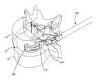
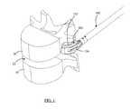
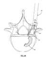
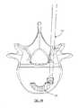
- FIGS. 1-3are perspective cut-away views of an exemplary process of inserting an exemplary implant using an exemplary inserter in accordance with the present invention
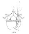
- FIGS. 4A and 4Bare perspective and top views, respectively, of an exemplary implant and inserter according to one embodiment of the present invention illustrating the positioning of the implant just after release from the inserter;
- FIGS. 5A and 5Bare top views of an exemplary implant and straight tamp in use according to one embodiment of the present invention.
- FIG. 5Cis a top view of an exemplary implant and footed tamp according to one embodiment of the present invention.
- FIG. 6Ais a top view of an exemplary scraper according to one embodiment of the present invention.
- FIG. 6Bis a top view of an exemplary rasp according to one embodiment of the present invention.
- FIG. 6Cis a top view of an exemplary straight tamp according to one embodiment of the present invention.
- FIG. 6Dis a top view of an exemplary footed tamp according to one embodiment of the present invention.
- FIG. 7Ais a perspective right side isometric view of an exemplary implant according to one embodiment of the present invention having the dimensions of 8 mm tall, 9 mm wide, and 20 mm long;
- FIG. 7Bis a perspective left side isometric view of the exemplary implant of FIG. 7A ;
- FIG. 7Cis a top view of the exemplary implant of FIG. 7A ;
- FIG. 7Dis a tool base engaging side view of the exemplary implant of FIG. 7A ;
- FIG. 7Eis an exploded view of a plurality of teeth located on the exemplary implant of FIG. 7A ;
- FIG. 7Fis a right side view of the exemplary implant of FIG. 7A ;
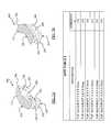
- FIGS. 8A and 8Bare perspective right and left side isometric views, respectively, of an exemplary implant according to one embodiment of the present invention having the dimensions of 8 mm tall, 11 mm wide, and 20 mm long;
- FIG. 8Cis a top view of the exemplary implant of FIG. 8A ;
- FIG. 8Dis a tool base engaging side view of the exemplary implant of FIG. 8A ;
- FIGS. 9A and 9Bare perspective right and left side isometric views, respectively, of an exemplary implant according to one embodiment of the present invention having the dimensions of 8 mm tall, 9 mm wide, and 25 mm long;
- FIG. 9Cis a top view of the exemplary implant of FIG. 9A ;
- FIG. 9Dis a tool base engaging side view of the exemplary implant of FIG. 9A ;
- FIG. 9Eis an exploded view of a plurality of teeth located on the exemplary implant of FIG. 9A ;
- FIG. 9Fis a right side view of the exemplary implant of FIG. 9A ;
- FIGS. 10A and 10Bare perspective right and left side isometric views, respectively, of an exemplary implant according to one embodiment of the present invention having the dimensions of 8 mm tall, 11 mm wide, and 25 mm long;
- FIG. 10Cis a top isometric view of the exemplary implant of FIG. 10A ;
- FIG. 10Dis a tool base engaging side view of the exemplary implant of FIG. 10A ;
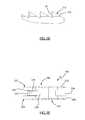
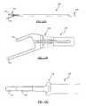
- FIG. 11is an exploded view of an exemplary 11 mm wide angled inserter according to one embodiment of the present invention, illustrating in particular the fork and collar components;
- FIG. 12Ais a top view of an exemplary 9 mm wide angled inserter according to one embodiment of the present invention.
- FIG. 12Bis a top view of an exemplary 11 mm wide angled inserter according to one embodiment of the present invention.
- FIG. 12Cis a side view of the exemplary 9 mm wide angled inserter of FIG. 12A ;
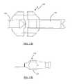
- FIG. 13Ais a top view of an exemplary fork component according to one embodiment of the present invention.
- FIG. 13Bis a side view of an exemplary angled implant insertion tool distal end according to one embodiment of the present invention.
- FIG. 13Cis a top view of the angled implant insertion tool distal end of FIG. 13B ;
- FIG. 13Dis a front view of the angled implant insertion tool distal end of FIG. 13B ;
- FIG. 13Eis a side view of an exemplary implant insertion tool proximal end according to one embodiment of the present invention.
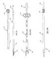
- FIG. 14is an exploded view of an exemplary 11 mm wide straight implant insertion tool according to one embodiment of the present invention, illustrating in particular the fork and collar components;
- FIG. 15Ais a top view of a fully assembled exemplary 11 mm wide straight implant insertion tool according to one embodiment of the present invention.
- FIG. 15Bis a side view diagram of an exemplary 11 mm wide straight implant insertion tool in accordance with one embodiment of the present invention.
- FIG. 16Ais a side view diagram of an exemplary 11 mm wide straight implant insertion tool fork in accordance with one embodiment of the present invention.
- FIG. 16Bis a top view diagram of an exemplary 11 mm wide straight implant insertion tool fork in accordance with one embodiment of the present invention.
- FIG. 16Cis a detailed top view diagram of an exemplary 11 mm wide straight implant insertion tool fork distal end in accordance with the present invention.
- FIG. 16Dis a detailed side view diagram of an exemplary 11 mm wide straight implant insertion tool fork distal end in accordance with the present invention.
- FIG. 16Eis a detailed side view diagram of an exemplary 11 mm wide implant insertion tool fork proximal end in accordance with one embodiment of the present invention.
- FIG. 16Fis a detailed end view diagram of an exemplary 11 mm wide implant insertion tool fork distal end in accordance with one embodiment of the present invention.
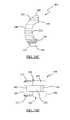
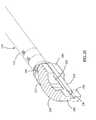
- FIG. 17is an isometric line diagram view of an exemplary 11 mm wide straight implant insertion tool distal end gripping an exemplary 11 mm wide, 20 mm long implant in accordance with one embodiment of the present invention
- FIG. 18is an isometric line diagram of an exemplary 9 mm wide straight implant insertion tool distal end gripping an exemplary 9 mm wide, 20 mm long implant in accordance with one embodiment of the present invention
- FIG. 19is an isometric line diagram of an exemplary 9 mm wide implant insertion tool distal end gripping an exemplary 9 mm wide, 25 mm long implant in accordance with one embodiment of the present invention
- FIG. 20is an isometric line diagram of an exemplary 11 mm wide implant insertion tool distal end gripping an exemplary 11 mm wide, 25 mm long implant in accordance with one embodiment of the present invention
- FIG. 21Ais a cross-sectional view of an in vivo spinal surgical procedure according to one embodiment of the present invention, illustrating in particular the use of a disc cutter to clear disc material from intradiscal space;
- FIG. 21Bis a cross-sectional view of an in vivo spinal surgical procedure according to one embodiment of the present invention, illustrating in particular the use of a curette to clear disc material from intradiscal space;
- FIG. 21Cis a cross-sectional view of an in vivo spinal surgical procedure according to one embodiment of the present invention, illustrating in particular the use of a scraper to clear disc material from intradiscal space;
- FIG. 21Dis a cross-sectional view of an in vivo spinal surgical procedure according to one embodiment of the present invention, illustrating in particular the use of a disc brush to clear disc material from intradiscal space;
- FIG. 21Eis a cross-sectional view of an in vivo spinal surgical procedure according to one embodiment of the present invention, illustrating in particular the use of a rasp to clear disc material from intradiscal space;
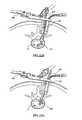
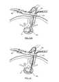
- FIGS. 22A-22Bare cross-sectional views of an in vivo spinal surgical procedure according to one embodiment of the present invention, illustrating in particular the insertion of an implant into the disc space using an angled inserter;
- FIGS. 23A-23Bare cross-sectional views of an in vivo spinal surgical procedure according to one embodiment of the present invention, illustrating in particular the insertion of an implant into the disc space using a straight inserter;
- FIG. 24is a cross-sectional view of an in vivo spinal surgical procedure according to one embodiment of the present invention, illustrating in particular the positioning of an implant within the disc space using a straight tamp;
- FIG. 25is a cross-sectional view of an in vivo spinal surgical procedure according to one embodiment of the present invention, illustrating in particular the addition and compaction of graft material within the disc space using a footed tamp;
- FIG. 26is a cross-sectional view of an in vivo spinal surgical procedure according to one embodiment of the present invention, illustrating in particular the final positioning of an implant within the disc space after conclusion of the procedure.
- the present inventionmay include a variety of devices for performing transforaminal lumbar interbody fusion, including but not limited to a variety of TLIF implants, implant inserters for inserting the TLIF implants into the intervertebral space, positioning devices for positioning the TLIF implants after insertion, and packing devices for packing additional materials within the disc space to promote fusion.
- Optional preparation devicesmay also be provided for preparing the intervertebral space prior to implant insertion. These devices will be described in detail below.
- FIGS. 1-3depict a cut-away view of an exemplary process of inserting an exemplary implant 200 using an exemplary inserter 100 in accordance with the present invention.
- an exemplary implant 200(shown in sectional view) is inserted via an inserter 100 into the disc space 12 of vertebrae 10 , 20 .
- Upper vertebra 20is shown in wire line view to more clearly show the advancement of the implant 200 and inserter from FIG. 1 to FIG. 3 into the disc space 12 .
- the inserter 100grips the implant 200 via a set of prongs 132 , 134 .
- the prongs 132 , 134are fluoroscopically opaque. Accordingly, as the implant 200 is advanced from a position outside the disc space 12 (as shown in FIG.
- the inserter 100 and method of the present inventionmay be used to accurately place an implant 200 within a disc space 12 regardless of the fluoroscopic properties of the implant (fluoroscopically opaque or transparent).
- FIGS. 4A-6Dillustrate an exemplary process of positioning implant 200 into a desired location according to one embodiment of the present invention.
- the implant 200is released from the inserter 100 as described in further detail below.
- a straight tamp 420may be used to guide implant 200 to a desired position.
- a clinicianmay add and pack in autograft or other fusion-assisting composition (such as bone morphogenic protein) using a footed tamp 430 , as shown in FIG. 5C .
- FIGS. 6A-6Dillustrate a variety of instruments that may be used according to the present invention.
- FIG. 6Adepicts a scraper 410 that may be used to clean out a disc space 12 prior to insertion of implant 200 .
- FIG. 6Bis a line drawing of an exemplary rasp 420 according to the present invention, used to further clean out the disc space 12 prior to insertion of implant 200 .
- FIG. 6Cis a line drawing of an exemplary straight tamp 430 according to one embodiment of the present invention, used to guide implant 200 into position after insertion into disc space 12 .
- FIG. 6Dis a line drawing of a footed tamp 440 according to the present invention, that may be used to insert and compress allograft material into the disc space 12 once implant 200 has been inserted and positioned.
- the implant 200 of the present inventionmay be provided in any number of suitable shapes and sizes. In a preferred embodiment, however, the implant 200 may comprise the exemplary shapes and size ranges as shown and detailed in FIGS. 7A-10D .
- the exemplary implant 200may have a width of 9 or 11 millimeters and a length of 20 or 25 millimeters. Further, as shown in Size Tables 1 - 4 , the exemplary implant 200 may have a height from 6 to 16 millimeters in 2 mm increments in one exemplary embodiment.
- the basic geometry of exemplary implant 200is similar for each of these size variations.
- the implant 200is crescent shaped with a top 210 , bottom 220 , proximal end 230 , distal end 260 , left side 240 , and right side 250 .
- the top 210 and bottom 220include a plurality of rows of teeth 212 where the teeth are designed to engage vertebra endplates upon insertion between vertebrae.
- the implant sides 230 , 240 , 250 , 260may include a plurality of tool engaging recesses 232 , 234 , 236 , and 242 .
- the left side 240 of implant 200is curved while the tool recess 242 is straight.
- the right side 250has a curved section 252 and flat sections corresponding to the tool engaging recesses 234 , 236 .
- the proximal end 230 of implant 200has a flat end and the tool engaging recess 232 also has a flat end with a pair of 45-degree offsets that mate with the tool recesses 234 , 242
- FIG. 7Ais a top, right side perspective view isometric line drawing of an exemplary implant 200 having dimensions of 8 mm tall, 9 mm wide, and 20 mm long.
- FIG. 7Bis a bottom, left side perspective view isometric line drawing of the exemplary implant 200 of FIG. 7A .
- FIGS. 7C and 7Dare top view and proximal end view line drawings, respectively, of the exemplary 8 mm tall, 9 mm wide, 20 mm long implant 200 .
- FIG. 7Eis a detailed view line drawing of several teeth 212 for an exemplary 8 mm tall, 20 mm long implant 200 .
- each toothhas a top 216 and side 218 wherein the top has a 60-degree inclination relative to the flat surface of the implant top 210 or bottom 220 .
- the exemplary 20 mm long implant 200has 22 such teeth 212 .
- FIG. 7Fis a right side view line drawing of the implant 200 of FIG. 7A illustrating the general shape of two 45-degree teeth 222 disposed on the proximal end 230 .
- FIG. 8Ais a top, right side isometric line drawing of an exemplary implant 204 having dimensions of 8 mm tall, 11 mm wide, and 20 mm long.
- FIG. 8Bis a bottom, left side isometric line drawing of the exemplary 8 mm tall, 11 mm wide, 20 mm long implant 204 .
- FIG. 8Cis a top view line drawing of the exemplary 8 mm tall, 11 mm wide, 20 mm long implant 204 .
- FIG. 8Dis a proximal end view line drawing of the exemplary 8 mm tall, 11 mm wide, 20 mm long implant 204 .
- FIG. 9Ais a top, right side isometric line drawing of an exemplary implant 202 having dimensions of 8 mm tall, 9 mm wide, and 25 mm long.
- FIG. 9Bis a bottom, left side isometric line drawing of the exemplary 8 mm tall, 9 mm wide, 25 mm long implant 202 .
- FIG. 9Cis a top view line drawing of the exemplary 8 mm tall, 9 mm wide, 25 mm long implant 202 .
- FIG. 9Dis a proximal end view line drawing of the exemplary 8 mm tall, 9 mm wide, 25 mm long implant 202 .
- FIG. 9Eis a detailed view line drawing of several teeth 212 for an exemplary 25 mm long implant 202 .
- each toothhas a top 216 and side 218 where the top has a 60-degree inclination relative to the flat surface of the implant top 210 or bottom 220 .
- the exemplary 25 mm long implant 200has 28 such teeth 212 .
- FIG. 9Fis a right side view line drawing of an exemplary 8 mm tall, 25 mm long implant 202 that indicates the dimensions of the two 45-degree teeth 222 .
- FIG. 10Ais a top, right side isometric line drawing of an exemplary implant 206 having dimensions of 8 mm tall, 11 mm wide, and 25 mm long.
- FIG. 10Bis a bottom, left side isometric line drawing of the exemplary 8 mm tall, 11 mm wide, 25 mm long implant 206 .
- FIG. 10Cis a top view line drawing of the exemplary 8 mm tall, 11 mm wide, 25 mm long implant 206 .
- FIG. 10Dis a proximal end view line drawing of the exemplary 8 mm tall, 11 mm wide, 25 mm long implant 206 of FIGS. 10A-10C .
- FIGS. 11-16Fare views of different configurations of the exemplary inserter 100 in accordance with the present invention.
- FIG. 11is an isometric line drawing of the 11 mm wide angled implant inserter 100 in its two parts: the collar 110 and fork 120 .
- the fork 120includes a shaft 122 , a proximal tool-engaging end 126 and a distal implant gripping end 124 .
- the proximal tool-engaging end 126includes a set of external threads 115 .
- the distal implant gripping end 124includes a set of prongs 132 , 134 for interaction with the implant 200 .
- the collar 110includes a hollow sleeve 112 dimensioned to slide over the proximal end 126 of the fork 120 and engage the distal end 124 .
- the collar 110includes a grip 114 with internal receiving threads 128 therein where the internal receiving threads 128 engage the external threads 115 of fork 120 when the sleeve 112 is slid over the proximal end 126 of fork and 120 approaches the distal end 124 .
- the grip 114is rotated clockwise to further advance the distal end of collar 110 .
- the distal end 124 of fork 120is dimensioned so that the collar 110 will compress the set of prongs 132 , 134 upon advancement of the distal end of collar 110 by clockwise rotation of the sleeve 112 via the grip 114 .
- the prongs 132 , 134may be advanced toward each other to securely engage the implant 200 upon clockwise rotation of the grip 114 .
- the implant 200may be similarly released from the prongs 132 , 134 by rotating the sleeve 112 counterclockwise when desired, such as when the implant is positioned in a desired location between vertebrae 10 and 20 as shown in FIG. 4 .
- FIGS. 12A & 12Bare top views of line drawings of the 9 mm and 11 mm, respectively, of angled implant inserters 100
- FIG. 12Cis a side view of the line drawing of the 9 mm wide angled implant inserter 100
- the inserter 100is shown with a length of about 10 inches from the distal end 124 to the grip 114 .
- inserter 100may be of any length desirable to insert the implant 200 into the desired location. This enables a clinician to use the inserter 100 to place an implant 200 between vertebrae in a minimally invasive procedure, such as via the use of a multi-blade retractor as described below.
- FIGS. 13A-13Eare line drawings of the exemplary 11 mm wide implant fork 120 .
- FIG. 13Ais a top view line drawing of one embodiment of the fork 120 , illustrating in particular the angled nature of prongs 132 , 134 . This angled relationship of prongs 132 , 134 enables an implant 200 to be slightly angled with respect to vertebrae 10 , 20 in turn allowing for a steeper (i.e. more vertical) angle of entry into the spinal column by the clinician.
- FIG. 13Bis a top view line drawing of the distal end 124 of fork 120
- FIG. 13Cis a side view line drawing of the distal end 124 of fork 120
- FIG. 13Dis an end view line drawing of the distal end 124 of fork 120 .
- the distal end 124includes a set of prongs 132 , 134 and a compressible section 136 .
- the first prong 132may be compressed toward the second prong 134 up to a distance of about 0.40 inches.
- FIG. 13Eis a side view line drawing of the tool engaging proximal end 126 of fork 120 .
- the tool engaging proximal end 126includes a formation 127 to allow coupling to a handle (not shown).
- FIGS. 14-16Fare line drawings of an exemplary embodiment of an 11 mm wide straight implant inserter 300 in accordance with the present invention.
- FIG. 14is an isometric line drawing of the 11 mm wide straight inserter in its two parts: the collar 310 and fork 320 .
- FIG. 15Ais a top view line drawing of the 11 mm wide implant inserter 300 and
- FIG. 15Bis a side view of the line drawing of the 11 mm wide implant inserter 300 .
- FIGS. 16A-16Fare line drawings of the exemplary 11 mm wide implant fork 320 .
- FIG. 16Ais a side view line drawing of the fork 320 that, in one embodiment, has an overall length of about 12.40 inches and a distal end 324 length of about 1.035 inches.
- FIG. 16Bis a top view line drawing of the fork 320
- FIG. 16Cis a top view line drawing of the distal end 324 of fork 320
- FIG. 16Dis a side view line drawing of the distal end 324 of fork 320
- FIG. 16Fis an end view line drawing of the distal end 324 of fork 320
- FIG. 16Eis a side view line drawing of the tool engaging proximal end 326 of the fork 320 .
- FIGS. 17-20are diagrams of the exemplary 9 and 11 mm wide implant inserter 100 gripping one of the 20 mm and 25 mm long implants 200 .
- FIG. 17is an isometric line drawing of an exemplary 11 mm wide implant inserter 100 gripping an exemplary 20 mm long implant 200 . As shown in these figures, the first prong 132 extends beyond implant end 260 .
- FIG. 18is an isometric line drawing of an exemplary 9 mm wide implant inserter 100 gripping an exemplary 20 mm long implant 200 .
- FIG. 19is an isometric line drawing of an exemplary 9 mm wide implant inserter 100 gripping an exemplary 25 mm long implant 200 . As shown in these figures, the implant end 260 extends slightly beyond the first prong 132 .
- FIG. 20is an isometric line drawing of an exemplary 11 mm wide implant inserter 100 gripping an exemplary 25 mm long implant 200 .
- the various devices described abovemay be provided with color-coding to facilitate ease-of-use for the surgeon. More specifically, all instruments and implants of a particular size may be provided with specific graphical and/or colored indicia such that the surgeon will know, simply by referring to the colored indicia, which instrument or implant he or she should employ from among the tray of instruments containing the instruments of the present invention.
- the 8 mm height implants and instrumentsmay be designated with a red color
- the 10 mm height implants and instrumentsmay be provided with a green color
- the 12 mm height implants and instrumentsmay be provided with a gold or yellow color
- the 14 mm height implants and instrumentsmay be provided with a blue color.
- the articles suitable for color-coding according to this feature of the present inventioninclude, but are not necessarily limited to, devices for sizing the disc space to determine what size implant should be inserted, the implant packaging, broaches, and implant inserters.
- FIGS. 21-26illustrate in greater detail a preferred embodiment of the fusion procedure according to the present invention.
- an incisionmay be made on the patient's skin at location postero-lateral to the desired implant location.
- a trocar or other instrumentmay be advanced to the annulus of the disc between the vertebrae 10 , 20 of interest.
- a cannula or similar devicemay then be advanced over the trocar to engage the disc annulus.
- a clinicianmay prefer to use a surgical retractor 400 to create an operating corridor 402 through which to insert the implant 200 .
- a clinicianmay perform an annulotomy to remove a section of the annulus and a discectomy thereafter to remove a portion of the disc where the implant 200 is to be placed. Further, the clinician may partially decorticate the endplates of the vertebrae 10 , 20 .
- FIGS. 21A-21Eillustrate an exemplary set of steps that may be taken to clean out the disc space 12 prior to insertion of implant 200 .
- FIG. 21Adepicts the use of a disc cutter 406 to remove disc material. To accomplish this, disc cutter 406 is employed with a rotating motion, and disc material is cut and loosened from the endplates of vertebrae 10 , 20 . Cut or loosened disc material is removed by removing the disc utter 406 .
- FIG. 21Billustrates the use of a curette 408 to further remove excess disc material and cartilage from the disc space 12 .
- FIG. 21Cdepicts the use of a scraper 410 to further remove disc material and cartilage from the endplates of vertebrae 10 , 20 .
- FIG. 21Dshows the use of a disc brush 412 to still further remove excess disc material.
- FIG. 21Eillustrates the use of a rasp 420 in an optional final step in preparing the endplates.
- the clinicianmay distract vertebrae 10 , 20 to expand the disc space to a desired height. Based on the distraction height and the size of the vertebrae 10 , 20 , the clinician may select a suitably dimensioned implant 200 .
- the implantis then placed between the prongs 132 , 134 located on the distal end 124 of inserter 100 .
- the prongs 132 , 134are then compressed by rotating the sleeve 112 via grip 114 to securely engage the implant 200 , as described above.
- the clinicianmay insert the implant 200 into the disc space 12 by passing the inserter 100 through the operative corridor 402 of the retractor 400 .
- the clinicianmay take several fluoroscopic pictures to determine the location of the implant 200 within the disc space 12 by observing the location of the distal end 124 of the inserter 100 , and in particular the set of prongs 132 , 134 .
- angled inserter 100may be used to insert implant 200 into disc space 12 .
- straight inserter 300may be used to insert implant 200 into disc space 12 at a 90-degree rotated orientation.
- the clinicianmay then rotate the implant 200 to obtain the desired special relationship, as shown in FIG. 23B .
- the clinicianmay release the implant 200 by rotating the sleeve 112 via the grip 114 counter-clockwise to decompress the set of prongs 132 , 134 .
- FIG. 24illustrates the use of a straight tamp 430 to guide the implant 200 to the desired position.
- FIG. 25illustrates the use of a footed tamp 440 used to insert and compress autograft or other fusion-promoting composition (such as bone morphogenic protein) 442 in the disc space 12 .
- 26depicts the final positioning of the implant 200 and the allograft material 442 at the close of the procedure according to the present invention.
- the clinicianmay remove any distraction means prior to the removal of the inserter 100 so the vertebral endplates of the vertebrae 10 , 20 engage with the teeth 112 on the top 210 and bottom 220 of implant 200 . Thereafter, the inserter 100 may be withdrawn, the annulotomy closed, the retractor 400 removed, and the incision closed.
- the exemplary inserter 100may be modified to handle implants having widths other than 9 and 11 mm. It is contemplated that spinal implants according to the present invention may have any width suitable for use in an intradiscal space. By way of example only, 14 mm wide implant inserter may be used in accordance with the present invention to insert a 14 mm wide spinal implant.
Landscapes
- Health & Medical Sciences (AREA)
- Engineering & Computer Science (AREA)
- Biomedical Technology (AREA)
- Orthopedic Medicine & Surgery (AREA)
- Transplantation (AREA)
- Neurology (AREA)
- Heart & Thoracic Surgery (AREA)
- Oral & Maxillofacial Surgery (AREA)
- Cardiology (AREA)
- Vascular Medicine (AREA)
- Life Sciences & Earth Sciences (AREA)
- Animal Behavior & Ethology (AREA)
- General Health & Medical Sciences (AREA)
- Public Health (AREA)
- Veterinary Medicine (AREA)
- Physical Education & Sports Medicine (AREA)
- Prostheses (AREA)
Abstract
Description
Claims (17)
Priority Applications (1)
| Application Number | Priority Date | Filing Date | Title |
|---|---|---|---|
| US10/887,542US7905886B1 (en) | 2003-07-07 | 2004-07-07 | System and methods for performing transforaminal lumbar interbody fusion |
Applications Claiming Priority (2)
| Application Number | Priority Date | Filing Date | Title |
|---|---|---|---|
| US48555903P | 2003-07-07 | 2003-07-07 | |
| US10/887,542US7905886B1 (en) | 2003-07-07 | 2004-07-07 | System and methods for performing transforaminal lumbar interbody fusion |
Publications (1)
| Publication Number | Publication Date |
|---|---|
| US7905886B1true US7905886B1 (en) | 2011-03-15 |
Family
ID=43708121
Family Applications (1)
| Application Number | Title | Priority Date | Filing Date |
|---|---|---|---|
| US10/887,542Expired - LifetimeUS7905886B1 (en) | 2003-07-07 | 2004-07-07 | System and methods for performing transforaminal lumbar interbody fusion |
Country Status (1)
| Country | Link |
|---|---|
| US (1) | US7905886B1 (en) |
Cited By (66)
| Publication number | Priority date | Publication date | Assignee | Title |
|---|---|---|---|---|
| WO2013149611A1 (en)* | 2012-04-05 | 2013-10-10 | Spine Center Baden GmbH | Spinal implant, tools for introducing implants between two vertebral bodies of a spinal column and surgical kit |
| US20130282018A1 (en)* | 2006-09-19 | 2013-10-24 | Warsaw Orthopedic Inc. | Instruments and methods for spinal implant revision |
| US20140135932A1 (en)* | 2006-02-15 | 2014-05-15 | Ldr Medical | Transforaminal intersomatic cage for an intervertebral fusion graft and an instrument for implanting the cage |
| FR3003157A1 (en)* | 2013-03-12 | 2014-09-19 | Neuro France Implants Nfi | POSTERO LATERAL INTERSOMATIC CAGE FOR REALIZING VERTEBRAL ARTHRODESIS |
| US20150025575A1 (en)* | 2008-12-05 | 2015-01-22 | Jeffrey KLEINER | Apparatus and Method of Spinal Implant and Fusion |
| US20150045891A1 (en)* | 2009-10-13 | 2015-02-12 | Nicholas Poulos | Expandable interbody implant and method |
| US20150066148A1 (en)* | 2010-06-02 | 2015-03-05 | Spinecraft, LLC | Intervertebral Implant Facilitating Unilateral Placement, Instruments and Methods |
| US8986307B2 (en) | 2012-07-10 | 2015-03-24 | X-Spine Systems, Inc. | Surgical instrument with pivotable implant holder |
| US20150119990A1 (en)* | 2010-04-21 | 2015-04-30 | SpineCraft,LLC | Intervertebral Body Implant, Instrument and Method |
| US9044334B2 (en) | 2010-07-21 | 2015-06-02 | Nlt Spine Ltd. | Spinal surgery implants and delivery system |
| US9060877B2 (en) | 2009-09-18 | 2015-06-23 | Spinal Surgical Strategies, Llc | Fusion cage with combined biological delivery system |
| US9173694B2 (en) | 2009-09-18 | 2015-11-03 | Spinal Surgical Strategies, Llc | Fusion cage with combined biological delivery system |
| US9186193B2 (en) | 2009-09-18 | 2015-11-17 | Spinal Surgical Strategies, Llc | Fusion cage with combined biological delivery system |
| US9247943B1 (en) | 2009-02-06 | 2016-02-02 | Kleiner Intellectual Property, Llc | Devices and methods for preparing an intervertebral workspace |
| USD750249S1 (en) | 2014-10-20 | 2016-02-23 | Spinal Surgical Strategies, Llc | Expandable fusion cage |
| US20160228170A1 (en)* | 2015-02-06 | 2016-08-11 | Alphatec Spine, Inc. | Implant insertion instrument |
| US9439782B2 (en) | 2008-02-06 | 2016-09-13 | Jeffrey B. Kleiner | Spinal fusion cage system with inserter |
| US9463091B2 (en) | 2009-09-17 | 2016-10-11 | Ldr Medical | Intervertebral implant having extendable bone fixation members |
| US9597194B2 (en) | 2005-09-23 | 2017-03-21 | Ldr Medical | Intervertebral disc prosthesis |
| US9629729B2 (en) | 2009-09-18 | 2017-04-25 | Spinal Surgical Strategies, Llc | Biological delivery system with adaptable fusion cage interface |
| US9730802B1 (en) | 2014-01-14 | 2017-08-15 | Nuvasive, Inc. | Spinal fusion implant and related methods |
| USD797290S1 (en) | 2015-10-19 | 2017-09-12 | Spinal Surgical Strategies, Llc | Bone graft delivery tool |
| US9795485B2 (en) | 2007-06-08 | 2017-10-24 | Ldr Medical | Intersomatic cage, intervertebral prosthesis, anchoring device and implantation instruments |
| US9833331B2 (en) | 2009-12-31 | 2017-12-05 | Ldr Medical | Anchoring device and system for an intervertebral implant, intervertebral implant and implantation instrument |
| US20170367840A1 (en)* | 2016-06-27 | 2017-12-28 | Globus Medical, Inc. | Intervertebral spacer with chamfered edges |
| US9877842B2 (en) | 2014-01-30 | 2018-01-30 | Ldr Medical | Anchoring device for a spinal implant, spinal implant and implantation instrumentation |
| US9987099B2 (en) | 2014-06-18 | 2018-06-05 | Covidien Lp | Disposable housings for encasing handle assemblies |
| US20180235776A1 (en)* | 2009-12-07 | 2018-08-23 | Samy Abdou | Devices and methods for minimally invasive spinal stablization and instrumentation |
| US10195053B2 (en) | 2009-09-18 | 2019-02-05 | Spinal Surgical Strategies, Llc | Bone graft delivery system and method for using same |
| US10245159B1 (en) | 2009-09-18 | 2019-04-02 | Spinal Surgical Strategies, Llc | Bone graft delivery system and method for using same |
| US10292825B2 (en)* | 2016-06-27 | 2019-05-21 | Globus Medical, Inc. | Intervertebral spacer with chamfered edges |
| US10321833B2 (en) | 2016-10-05 | 2019-06-18 | Innovative Surgical Solutions. | Neural locating method |
| US10376209B2 (en) | 2013-09-20 | 2019-08-13 | Innovative Surgical Solutions, Llc | Neural locating method |
| US10376208B2 (en) | 2013-09-20 | 2019-08-13 | Innovative Surgical Solutions, Llc | Nerve mapping system |
| US10426468B2 (en) | 2015-04-22 | 2019-10-01 | Covidien Lp | Handheld electromechanical surgical system |
| US10449002B2 (en) | 2013-09-20 | 2019-10-22 | Innovative Surgical Solutions, Llc | Method of mapping a nerve |
| US10478096B2 (en) | 2013-08-13 | 2019-11-19 | Innovative Surgical Solutions. | Neural event detection |
| US10478097B2 (en) | 2013-08-13 | 2019-11-19 | Innovative Surgical Solutions | Neural event detection |
| US10537447B2 (en)* | 2018-03-30 | 2020-01-21 | Warsaw Orthopedic, Inc. | Radiolucent trial |
| US10548740B1 (en) | 2016-10-25 | 2020-02-04 | Samy Abdou | Devices and methods for vertebral bone realignment |
| US10575961B1 (en) | 2011-09-23 | 2020-03-03 | Samy Abdou | Spinal fixation devices and methods of use |
| US10695105B2 (en) | 2012-08-28 | 2020-06-30 | Samy Abdou | Spinal fixation devices and methods of use |
| US10857003B1 (en) | 2015-10-14 | 2020-12-08 | Samy Abdou | Devices and methods for vertebral stabilization |
| US10870002B2 (en) | 2018-10-12 | 2020-12-22 | DePuy Synthes Products, Inc. | Neuromuscular sensing device with multi-sensor array |
| US10869616B2 (en) | 2018-06-01 | 2020-12-22 | DePuy Synthes Products, Inc. | Neural event detection |
| US10918498B2 (en) | 2004-11-24 | 2021-02-16 | Samy Abdou | Devices and methods for inter-vertebral orthopedic device placement |
| US10973656B2 (en) | 2009-09-18 | 2021-04-13 | Spinal Surgical Strategies, Inc. | Bone graft delivery system and method for using same |
| US10973648B1 (en) | 2016-10-25 | 2021-04-13 | Samy Abdou | Devices and methods for vertebral bone realignment |
| US11006982B2 (en) | 2012-02-22 | 2021-05-18 | Samy Abdou | Spinous process fixation devices and methods of use |
| US20210290408A1 (en)* | 2008-10-13 | 2021-09-23 | Globus Medical, Inc. | Intervertebral spacer |
| US11166825B1 (en) | 2020-07-01 | 2021-11-09 | Warsaw Orthopedic, Inc. | Spinal implant |
| US11173040B2 (en) | 2012-10-22 | 2021-11-16 | Cogent Spine, LLC | Devices and methods for spinal stabilization and instrumentation |
| US11179248B2 (en) | 2018-10-02 | 2021-11-23 | Samy Abdou | Devices and methods for spinal implantation |
| US11278286B2 (en) | 2015-04-22 | 2022-03-22 | Covidien Lp | Handheld electromechanical surgical system |
| US11298244B2 (en) | 2019-01-31 | 2022-04-12 | K2M, Inc. | Interbody implants and instrumentation |
| US11399777B2 (en) | 2019-09-27 | 2022-08-02 | DePuy Synthes Products, Inc. | Intraoperative neural monitoring system and method |
| US20220257337A1 (en)* | 2019-11-15 | 2022-08-18 | Aesculap Ag | Implant system |
| US11464651B2 (en)* | 2019-09-11 | 2022-10-11 | L&K Biomed Co., Ltd. | Cage holder for spinal fusion cage |
| US11534307B2 (en) | 2019-09-16 | 2022-12-27 | K2M, Inc. | 3D printed cervical standalone implant |
| US11666455B2 (en) | 2009-09-18 | 2023-06-06 | Spinal Surgical Strategies, Inc., A Nevada Corporation | Bone graft delivery devices, systems and kits |
| US11793558B2 (en) | 2019-08-30 | 2023-10-24 | K2M, Inc. | All in one plate holder and spring loaded awl |
| US11801061B2 (en)* | 2012-12-08 | 2023-10-31 | Retrospine Pty Ltd | System and method for inserting an intervertebral cage into a spine |
| US11957598B2 (en) | 2004-02-04 | 2024-04-16 | Ldr Medical | Intervertebral disc prosthesis |
| US12279972B2 (en) | 2008-05-22 | 2025-04-22 | Spinal Surgical Strategies, Inc. | Spinal fusion cage system with inserter |
| USD1086449S1 (en) | 2015-03-25 | 2025-07-29 | Orthocision Inc. | Surgical cannula |
| US12403018B2 (en) | 2016-11-01 | 2025-09-02 | Warsaw Orthopedic, Inc. | Expandable spinal implant system and method of using same |
Citations (15)
| Publication number | Priority date | Publication date | Assignee | Title |
|---|---|---|---|---|
| US5339801A (en)* | 1992-03-12 | 1994-08-23 | Uresil Corporation | Surgical retractor and surgical method |
| US5341707A (en)* | 1992-06-23 | 1994-08-30 | Klein Tools, Inc. | Head indicia to indicate tool type |
| US5573529A (en)* | 1994-10-31 | 1996-11-12 | Haak; Benjamin A. | Color coded medical instruments |
| US5857995A (en)* | 1996-08-15 | 1999-01-12 | Surgical Dynamics, Inc. | Multiple bladed surgical cutting device removably connected to a rotary drive element |
| US6174311B1 (en)* | 1998-10-28 | 2001-01-16 | Sdgi Holdings, Inc. | Interbody fusion grafts and instrumentation |
| US6261296B1 (en)* | 1998-10-02 | 2001-07-17 | Synthes U.S.A. | Spinal disc space distractor |
| US20010010833A1 (en)* | 1999-09-10 | 2001-08-02 | Ray-Griffin, Inc. | Process of making a set of distinguishable robertson driver bits |
| US20020019637A1 (en)* | 1999-10-21 | 2002-02-14 | George Frey | Devices and techniques for a posterior lateral disc space approach |
| US6440170B1 (en)* | 2000-12-04 | 2002-08-27 | Roger P. Jackson | Threaded interbody device |
| US6524318B1 (en)* | 1999-10-18 | 2003-02-25 | Sulzer Spine-Tech Inc. | Spinal surgery instruments and methods |
| US20030135275A1 (en)* | 2001-11-09 | 2003-07-17 | Javier Garcia | Instruments and methods for inserting a spinal implant |
| US6663562B2 (en)* | 2001-09-14 | 2003-12-16 | David Chang | Surgical retractor |
| US20040143332A1 (en)* | 2002-10-31 | 2004-07-22 | Krueger David J. | Movable disc implant |
| US6852126B2 (en)* | 2000-07-17 | 2005-02-08 | Nuvasive, Inc. | Stackable interlocking intervertebral support system |
| US6923814B1 (en)* | 2001-10-30 | 2005-08-02 | Nuvasive, Inc. | System and methods for cervical spinal fusion |
- 2004
- 2004-07-07USUS10/887,542patent/US7905886B1/ennot_activeExpired - Lifetime
Patent Citations (15)
| Publication number | Priority date | Publication date | Assignee | Title |
|---|---|---|---|---|
| US5339801A (en)* | 1992-03-12 | 1994-08-23 | Uresil Corporation | Surgical retractor and surgical method |
| US5341707A (en)* | 1992-06-23 | 1994-08-30 | Klein Tools, Inc. | Head indicia to indicate tool type |
| US5573529A (en)* | 1994-10-31 | 1996-11-12 | Haak; Benjamin A. | Color coded medical instruments |
| US5857995A (en)* | 1996-08-15 | 1999-01-12 | Surgical Dynamics, Inc. | Multiple bladed surgical cutting device removably connected to a rotary drive element |
| US6261296B1 (en)* | 1998-10-02 | 2001-07-17 | Synthes U.S.A. | Spinal disc space distractor |
| US6174311B1 (en)* | 1998-10-28 | 2001-01-16 | Sdgi Holdings, Inc. | Interbody fusion grafts and instrumentation |
| US20010010833A1 (en)* | 1999-09-10 | 2001-08-02 | Ray-Griffin, Inc. | Process of making a set of distinguishable robertson driver bits |
| US6524318B1 (en)* | 1999-10-18 | 2003-02-25 | Sulzer Spine-Tech Inc. | Spinal surgery instruments and methods |
| US20020019637A1 (en)* | 1999-10-21 | 2002-02-14 | George Frey | Devices and techniques for a posterior lateral disc space approach |
| US6852126B2 (en)* | 2000-07-17 | 2005-02-08 | Nuvasive, Inc. | Stackable interlocking intervertebral support system |
| US6440170B1 (en)* | 2000-12-04 | 2002-08-27 | Roger P. Jackson | Threaded interbody device |
| US6663562B2 (en)* | 2001-09-14 | 2003-12-16 | David Chang | Surgical retractor |
| US6923814B1 (en)* | 2001-10-30 | 2005-08-02 | Nuvasive, Inc. | System and methods for cervical spinal fusion |
| US20030135275A1 (en)* | 2001-11-09 | 2003-07-17 | Javier Garcia | Instruments and methods for inserting a spinal implant |
| US20040143332A1 (en)* | 2002-10-31 | 2004-07-22 | Krueger David J. | Movable disc implant |
Cited By (131)
| Publication number | Priority date | Publication date | Assignee | Title |
|---|---|---|---|---|
| US11957598B2 (en) | 2004-02-04 | 2024-04-16 | Ldr Medical | Intervertebral disc prosthesis |
| US10918498B2 (en) | 2004-11-24 | 2021-02-16 | Samy Abdou | Devices and methods for inter-vertebral orthopedic device placement |
| US11992423B2 (en) | 2004-11-24 | 2024-05-28 | Samy Abdou | Devices and methods for inter-vertebral orthopedic device placement |
| US11096799B2 (en) | 2004-11-24 | 2021-08-24 | Samy Abdou | Devices and methods for inter-vertebral orthopedic device placement |
| US9597194B2 (en) | 2005-09-23 | 2017-03-21 | Ldr Medical | Intervertebral disc prosthesis |
| US11872138B2 (en) | 2005-09-23 | 2024-01-16 | Ldr Medical | Intervertebral disc prosthesis |
| US10492919B2 (en) | 2005-09-23 | 2019-12-03 | Ldr Medical | Intervertebral disc prosthesis |
| US10758363B2 (en) | 2006-02-15 | 2020-09-01 | Ldr Medical | Transforaminal intersomatic cage for an intervertebral fusion graft and an instrument for implanting the cage |
| US9713535B2 (en) | 2006-02-15 | 2017-07-25 | Ldr Medical | Transforaminal intersomatic cage for an intervertebral fusion graft and an instrument for implanting the cage |
| US20140135932A1 (en)* | 2006-02-15 | 2014-05-15 | Ldr Medical | Transforaminal intersomatic cage for an intervertebral fusion graft and an instrument for implanting the cage |
| US9597198B2 (en)* | 2006-02-15 | 2017-03-21 | Ldr Medical | Transforaminal intersomatic cage for an intervertebral fusion graft and an instrument for implanting the cage |
| US20130282018A1 (en)* | 2006-09-19 | 2013-10-24 | Warsaw Orthopedic Inc. | Instruments and methods for spinal implant revision |
| US10751187B2 (en) | 2007-06-08 | 2020-08-25 | Ldr Medical | Intersomatic cage, intervertebral prosthesis, anchoring device and implantation instruments |
| US9795485B2 (en) | 2007-06-08 | 2017-10-24 | Ldr Medical | Intersomatic cage, intervertebral prosthesis, anchoring device and implantation instruments |
| US9439782B2 (en) | 2008-02-06 | 2016-09-13 | Jeffrey B. Kleiner | Spinal fusion cage system with inserter |
| US11129730B2 (en) | 2008-02-06 | 2021-09-28 | Spinal Surgical Strategies, Inc., a Nevada corpora | Spinal fusion cage system with inserter |
| US10179054B2 (en) | 2008-02-06 | 2019-01-15 | Jeffrey B. Kleiner | Spinal fusion cage system with inserter |
| US12279972B2 (en) | 2008-05-22 | 2025-04-22 | Spinal Surgical Strategies, Inc. | Spinal fusion cage system with inserter |
| US11896497B2 (en)* | 2008-10-13 | 2024-02-13 | Globus Medical, Inc. | Intervertebral spacer |
| US20210290408A1 (en)* | 2008-10-13 | 2021-09-23 | Globus Medical, Inc. | Intervertebral spacer |
| US9427264B2 (en)* | 2008-12-05 | 2016-08-30 | Jeffrey KLEINER | Apparatus and method of spinal implant and fusion |
| US20150025575A1 (en)* | 2008-12-05 | 2015-01-22 | Jeffrey KLEINER | Apparatus and Method of Spinal Implant and Fusion |
| US9861496B2 (en) | 2008-12-05 | 2018-01-09 | Jeffrey B. Kleiner | Apparatus and method of spinal implant and fusion |
| US10201355B2 (en) | 2009-02-06 | 2019-02-12 | Kleiner Intellectual Property, Llc | Angled surgical tool for removing tissue from within an intervertebral space |
| US9247943B1 (en) | 2009-02-06 | 2016-02-02 | Kleiner Intellectual Property, Llc | Devices and methods for preparing an intervertebral workspace |
| US9826988B2 (en) | 2009-02-06 | 2017-11-28 | Kleiner Intellectual Property, Llc | Devices and methods for preparing an intervertebral workspace |
| US9463091B2 (en) | 2009-09-17 | 2016-10-11 | Ldr Medical | Intervertebral implant having extendable bone fixation members |
| US10195053B2 (en) | 2009-09-18 | 2019-02-05 | Spinal Surgical Strategies, Llc | Bone graft delivery system and method for using same |
| US11660208B2 (en) | 2009-09-18 | 2023-05-30 | Spinal Surgical Strategies, Inc. | Bone graft delivery system and method for using same |
| US9173694B2 (en) | 2009-09-18 | 2015-11-03 | Spinal Surgical Strategies, Llc | Fusion cage with combined biological delivery system |
| US9186193B2 (en) | 2009-09-18 | 2015-11-17 | Spinal Surgical Strategies, Llc | Fusion cage with combined biological delivery system |
| US10973656B2 (en) | 2009-09-18 | 2021-04-13 | Spinal Surgical Strategies, Inc. | Bone graft delivery system and method for using same |
| US12053393B2 (en) | 2009-09-18 | 2024-08-06 | Spinal Surgical Strategies, Inc. | Bone graft delivery system and method for use |
| US9629729B2 (en) | 2009-09-18 | 2017-04-25 | Spinal Surgical Strategies, Llc | Biological delivery system with adaptable fusion cage interface |
| US11666455B2 (en) | 2009-09-18 | 2023-06-06 | Spinal Surgical Strategies, Inc., A Nevada Corporation | Bone graft delivery devices, systems and kits |
| US10245159B1 (en) | 2009-09-18 | 2019-04-02 | Spinal Surgical Strategies, Llc | Bone graft delivery system and method for using same |
| US9060877B2 (en) | 2009-09-18 | 2015-06-23 | Spinal Surgical Strategies, Llc | Fusion cage with combined biological delivery system |
| US12167971B2 (en) | 2009-09-18 | 2024-12-17 | Spinal Surgical Strategies, Inc. | Bone graft delivery devices, systems and kits |
| US20150045891A1 (en)* | 2009-10-13 | 2015-02-12 | Nicholas Poulos | Expandable interbody implant and method |
| US9211195B2 (en)* | 2009-10-13 | 2015-12-15 | Nicholas Poulos | Expandable interbody implant and method |
| US10857004B2 (en)* | 2009-12-07 | 2020-12-08 | Samy Abdou | Devices and methods for minimally invasive spinal stabilization and instrumentation |
| US10945861B2 (en) | 2009-12-07 | 2021-03-16 | Samy Abdou | Devices and methods for minimally invasive spinal stabilization and instrumentation |
| US11918486B2 (en) | 2009-12-07 | 2024-03-05 | Samy Abdou | Devices and methods for minimally invasive spinal stabilization and instrumentation |
| US20180235776A1 (en)* | 2009-12-07 | 2018-08-23 | Samy Abdou | Devices and methods for minimally invasive spinal stablization and instrumentation |
| US10610380B2 (en) | 2009-12-07 | 2020-04-07 | Samy Abdou | Devices and methods for minimally invasive spinal stabilization and instrumentation |
| US10543107B2 (en) | 2009-12-07 | 2020-01-28 | Samy Abdou | Devices and methods for minimally invasive spinal stabilization and instrumentation |
| US10195046B2 (en) | 2009-12-31 | 2019-02-05 | Ldr Medical | Instruments and methods for removing fixation devices from intervertebral implants |
| US11246715B2 (en) | 2009-12-31 | 2022-02-15 | Ldr Medical | Anchoring device and system for an intervertebral implant, intervertebral implant and implantation instrument |
| US9833331B2 (en) | 2009-12-31 | 2017-12-05 | Ldr Medical | Anchoring device and system for an intervertebral implant, intervertebral implant and implantation instrument |
| US10531961B2 (en) | 2009-12-31 | 2020-01-14 | Ldr Medical | Anchoring device and system for an intervertebral implant, intervertebral implant and implantation instrument |
| US20150119990A1 (en)* | 2010-04-21 | 2015-04-30 | SpineCraft,LLC | Intervertebral Body Implant, Instrument and Method |
| US9351849B2 (en)* | 2010-06-02 | 2016-05-31 | Spinecraft, LLC | Intervertebral implant facilitating unilateral placement, instruments and methods |
| US20150066148A1 (en)* | 2010-06-02 | 2015-03-05 | Spinecraft, LLC | Intervertebral Implant Facilitating Unilateral Placement, Instruments and Methods |
| US9044334B2 (en) | 2010-07-21 | 2015-06-02 | Nlt Spine Ltd. | Spinal surgery implants and delivery system |
| US11324608B2 (en) | 2011-09-23 | 2022-05-10 | Samy Abdou | Spinal fixation devices and methods of use |
| US12167973B2 (en) | 2011-09-23 | 2024-12-17 | Samy Abdou | Spinal fixation devices and methods of use |
| US10575961B1 (en) | 2011-09-23 | 2020-03-03 | Samy Abdou | Spinal fixation devices and methods of use |
| US11517449B2 (en) | 2011-09-23 | 2022-12-06 | Samy Abdou | Spinal fixation devices and methods of use |
| US11006982B2 (en) | 2012-02-22 | 2021-05-18 | Samy Abdou | Spinous process fixation devices and methods of use |
| US11839413B2 (en) | 2012-02-22 | 2023-12-12 | Samy Abdou | Spinous process fixation devices and methods of use |
| WO2013149611A1 (en)* | 2012-04-05 | 2013-10-10 | Spine Center Baden GmbH | Spinal implant, tools for introducing implants between two vertebral bodies of a spinal column and surgical kit |
| US8986307B2 (en) | 2012-07-10 | 2015-03-24 | X-Spine Systems, Inc. | Surgical instrument with pivotable implant holder |
| US10695105B2 (en) | 2012-08-28 | 2020-06-30 | Samy Abdou | Spinal fixation devices and methods of use |
| US11559336B2 (en) | 2012-08-28 | 2023-01-24 | Samy Abdou | Spinal fixation devices and methods of use |
| US11918483B2 (en) | 2012-10-22 | 2024-03-05 | Cogent Spine Llc | Devices and methods for spinal stabilization and instrumentation |
| US11173040B2 (en) | 2012-10-22 | 2021-11-16 | Cogent Spine, LLC | Devices and methods for spinal stabilization and instrumentation |
| US11801061B2 (en)* | 2012-12-08 | 2023-10-31 | Retrospine Pty Ltd | System and method for inserting an intervertebral cage into a spine |
| FR3003157A1 (en)* | 2013-03-12 | 2014-09-19 | Neuro France Implants Nfi | POSTERO LATERAL INTERSOMATIC CAGE FOR REALIZING VERTEBRAL ARTHRODESIS |
| US10478097B2 (en) | 2013-08-13 | 2019-11-19 | Innovative Surgical Solutions | Neural event detection |
| US10478096B2 (en) | 2013-08-13 | 2019-11-19 | Innovative Surgical Solutions. | Neural event detection |
| US10376209B2 (en) | 2013-09-20 | 2019-08-13 | Innovative Surgical Solutions, Llc | Neural locating method |
| US10376208B2 (en) | 2013-09-20 | 2019-08-13 | Innovative Surgical Solutions, Llc | Nerve mapping system |
| US10449002B2 (en) | 2013-09-20 | 2019-10-22 | Innovative Surgical Solutions, Llc | Method of mapping a nerve |
| US11497621B2 (en) | 2014-01-14 | 2022-11-15 | Nuvasive, Inc. | Inserter for implanting a spinal implant |
| US10335287B2 (en) | 2014-01-14 | 2019-07-02 | Nuvasive, Inc. | Spinal fusion implant and related methods |
| US9730802B1 (en) | 2014-01-14 | 2017-08-15 | Nuvasive, Inc. | Spinal fusion implant and related methods |
| US12127948B2 (en) | 2014-01-14 | 2024-10-29 | Globus Medical Inc. | System for implanting a spinal fusion implant and related methods |
| US9877842B2 (en) | 2014-01-30 | 2018-01-30 | Ldr Medical | Anchoring device for a spinal implant, spinal implant and implantation instrumentation |
| US10245157B2 (en) | 2014-01-30 | 2019-04-02 | Ldr Medical | Anchoring device for a spinal implant, spinal implant and implantation instrumentation |
| US10799317B2 (en) | 2014-06-18 | 2020-10-13 | Covidien Lp | Disposable housings for encasing handle assemblies and methods of use |
| US9987099B2 (en) | 2014-06-18 | 2018-06-05 | Covidien Lp | Disposable housings for encasing handle assemblies |
| USD750249S1 (en) | 2014-10-20 | 2016-02-23 | Spinal Surgical Strategies, Llc | Expandable fusion cage |
| US11547578B2 (en) | 2015-02-06 | 2023-01-10 | Alphatec Spine, Inc. | Implant insertion instrument |
| US10792168B2 (en)* | 2015-02-06 | 2020-10-06 | Alphatec Spine, Inc. | Implant insertion instrument |
| US20160228170A1 (en)* | 2015-02-06 | 2016-08-11 | Alphatec Spine, Inc. | Implant insertion instrument |
| USD1086449S1 (en) | 2015-03-25 | 2025-07-29 | Orthocision Inc. | Surgical cannula |
| US11278286B2 (en) | 2015-04-22 | 2022-03-22 | Covidien Lp | Handheld electromechanical surgical system |
| US10426466B2 (en) | 2015-04-22 | 2019-10-01 | Covidien Lp | Handheld electromechanical surgical system |
| US11382623B2 (en) | 2015-04-22 | 2022-07-12 | Covidien Lp | Handheld electromechanical surgical system |
| US10426468B2 (en) | 2015-04-22 | 2019-10-01 | Covidien Lp | Handheld electromechanical surgical system |
| US11918216B2 (en) | 2015-04-22 | 2024-03-05 | Covidien Lp | Handheld electromechanical surgical system |
| US10857003B1 (en) | 2015-10-14 | 2020-12-08 | Samy Abdou | Devices and methods for vertebral stabilization |
| US11246718B2 (en) | 2015-10-14 | 2022-02-15 | Samy Abdou | Devices and methods for vertebral stabilization |
| USD797290S1 (en) | 2015-10-19 | 2017-09-12 | Spinal Surgical Strategies, Llc | Bone graft delivery tool |
| US10292825B2 (en)* | 2016-06-27 | 2019-05-21 | Globus Medical, Inc. | Intervertebral spacer with chamfered edges |
| US10292834B2 (en)* | 2016-06-27 | 2019-05-21 | Globus Medical, Inc. | Intervertebral spacer with chamfered edges |
| JP2018023763A (en)* | 2016-06-27 | 2018-02-15 | グローバス メディカル インコーポレイティッド | Intervertebral spacer with chamfered edges |
| US20170367840A1 (en)* | 2016-06-27 | 2017-12-28 | Globus Medical, Inc. | Intervertebral spacer with chamfered edges |
| US11311222B2 (en) | 2016-10-05 | 2022-04-26 | Innovative Surgical Solutions | Neural locating system |
| US12109042B2 (en) | 2016-10-05 | 2024-10-08 | Innovative Surgical Solutions, Llc | Neural locating system and method |
| US10321833B2 (en) | 2016-10-05 | 2019-06-18 | Innovative Surgical Solutions. | Neural locating method |
| US11752008B1 (en) | 2016-10-25 | 2023-09-12 | Samy Abdou | Devices and methods for vertebral bone realignment |
| US10744000B1 (en) | 2016-10-25 | 2020-08-18 | Samy Abdou | Devices and methods for vertebral bone realignment |
| US10973648B1 (en) | 2016-10-25 | 2021-04-13 | Samy Abdou | Devices and methods for vertebral bone realignment |
| US10548740B1 (en) | 2016-10-25 | 2020-02-04 | Samy Abdou | Devices and methods for vertebral bone realignment |
| US11259935B1 (en) | 2016-10-25 | 2022-03-01 | Samy Abdou | Devices and methods for vertebral bone realignment |
| US11058548B1 (en) | 2016-10-25 | 2021-07-13 | Samy Abdou | Devices and methods for vertebral bone realignment |
| US12403018B2 (en) | 2016-11-01 | 2025-09-02 | Warsaw Orthopedic, Inc. | Expandable spinal implant system and method of using same |
| US10537447B2 (en)* | 2018-03-30 | 2020-01-21 | Warsaw Orthopedic, Inc. | Radiolucent trial |
| US11266514B2 (en)* | 2018-03-30 | 2022-03-08 | Warsaw Orthopedic, Inc. | Radiolucent trial |
| US10869616B2 (en) | 2018-06-01 | 2020-12-22 | DePuy Synthes Products, Inc. | Neural event detection |
| US11179248B2 (en) | 2018-10-02 | 2021-11-23 | Samy Abdou | Devices and methods for spinal implantation |
| US12090320B2 (en) | 2018-10-12 | 2024-09-17 | DePuy Synthes Products, Inc. | Neuromuscular sensing device with multi-sensor array |
| US10870002B2 (en) | 2018-10-12 | 2020-12-22 | DePuy Synthes Products, Inc. | Neuromuscular sensing device with multi-sensor array |
| US11969357B2 (en) | 2019-01-31 | 2024-04-30 | K2M, Inc. | Tritanium AL implants and instrumentation |
| US11918487B2 (en) | 2019-01-31 | 2024-03-05 | K2M, Inc. | Interbody implants and instrumentation |
| US11298244B2 (en) | 2019-01-31 | 2022-04-12 | K2M, Inc. | Interbody implants and instrumentation |
| US11617659B2 (en) | 2019-01-31 | 2023-04-04 | K2M, Inc. | Tritanium Al implants and instrumentation |
| US12226320B2 (en) | 2019-01-31 | 2025-02-18 | K2M, Inc. | Tritanium AL implants and instrumentation |
| US12303401B2 (en) | 2019-01-31 | 2025-05-20 | K2M, Inc. | Tritanium AL implants and instrumentation |
| US11793558B2 (en) | 2019-08-30 | 2023-10-24 | K2M, Inc. | All in one plate holder and spring loaded awl |
| US12201335B2 (en) | 2019-08-30 | 2025-01-21 | K2M, Inc. | All in one plate holder and spring loaded awl |
| US11464651B2 (en)* | 2019-09-11 | 2022-10-11 | L&K Biomed Co., Ltd. | Cage holder for spinal fusion cage |
| US12409045B2 (en) | 2019-09-16 | 2025-09-09 | Vb Spine Us Opco Llc | 3D printed cervical standalone implant |
| US11534307B2 (en) | 2019-09-16 | 2022-12-27 | K2M, Inc. | 3D printed cervical standalone implant |
| US12303301B2 (en) | 2019-09-27 | 2025-05-20 | DePuy Synthes Products, Inc. | Intraoperative neural monitoring system and method |
| US11399777B2 (en) | 2019-09-27 | 2022-08-02 | DePuy Synthes Products, Inc. | Intraoperative neural monitoring system and method |
| US20220257337A1 (en)* | 2019-11-15 | 2022-08-18 | Aesculap Ag | Implant system |
| US12433715B2 (en)* | 2019-11-15 | 2025-10-07 | Aesculap Ag | Implant system |
| US11166825B1 (en) | 2020-07-01 | 2021-11-09 | Warsaw Orthopedic, Inc. | Spinal implant |
| US12059357B2 (en) | 2020-07-01 | 2024-08-13 | Warsaw Orthopedic, Inc. | Spinal implant |
Similar Documents
| Publication | Publication Date | Title |
|---|---|---|
| US7905886B1 (en) | System and methods for performing transforaminal lumbar interbody fusion | |
| US12016783B2 (en) | Implants and methods for spinal fusion | |
| US20210267765A1 (en) | Systems and methods for spinal fusion | |
| USRE46647E1 (en) | Intervertebral implant for transforaminal posterior lumbar interbody fusion procedure | |
| AU2002309636B2 (en) | Intervertebral implant for transforaminal posterior lumbar interbody fusion procedure |
Legal Events
| Date | Code | Title | Description |
|---|---|---|---|
| AS | Assignment | Owner name:NUVASIVE, INC., CALIFORNIA Free format text:ASSIGNMENT OF ASSIGNORS INTEREST;ASSIGNORS:CURRAN, MATTHEW;WOOLLEY, TROY B.;MILES, PATRICK;SIGNING DATES FROM 20041119 TO 20041215;REEL/FRAME:016083/0494 | |
| STCF | Information on status: patent grant | Free format text:PATENTED CASE | |
| FPAY | Fee payment | Year of fee payment:4 | |
| AS | Assignment | Owner name:BANK OF AMERICA, N.A., AS ADMINISTRATIVE AGENT, CALIFORNIA Free format text:NOTICE OF GRANT OF SECURITY INTEREST IN PATENTS;ASSIGNORS:NUVASIVE, INC.;IMPULSE MONITORING, INC.;REEL/FRAME:040634/0404 Effective date:20160208 Owner name:BANK OF AMERICA, N.A., AS ADMINISTRATIVE AGENT, CA Free format text:NOTICE OF GRANT OF SECURITY INTEREST IN PATENTS;ASSIGNORS:NUVASIVE, INC.;IMPULSE MONITORING, INC.;REEL/FRAME:040634/0404 Effective date:20160208 | |
| AS | Assignment | Owner name:BANK OF AMERICA, N.A., AS ADMINISTRATIVE AGENT, TE Free format text:NOTICE OF GRANT OF SECURITY INTEREST IN PATENTS;ASSIGNORS:NUVASIVE, INC.;BIOTRONIC NATIONAL, LLC;NUVASIVE CLINICAL SERVICES MONITORING, INC.;AND OTHERS;REEL/FRAME:042490/0236 Effective date:20170425 Owner name:BANK OF AMERICA, N.A., AS ADMINISTRATIVE AGENT, TEXAS Free format text:NOTICE OF GRANT OF SECURITY INTEREST IN PATENTS;ASSIGNORS:NUVASIVE, INC.;BIOTRONIC NATIONAL, LLC;NUVASIVE CLINICAL SERVICES MONITORING, INC.;AND OTHERS;REEL/FRAME:042490/0236 Effective date:20170425 | |
| MAFP | Maintenance fee payment | Free format text:PAYMENT OF MAINTENANCE FEE, 8TH YEAR, LARGE ENTITY (ORIGINAL EVENT CODE: M1552); ENTITY STATUS OF PATENT OWNER: LARGE ENTITY Year of fee payment:8 | |
| AS | Assignment | Owner name:BANK OF AMERICA, N.A., AS ADMINISTRATIVE AGENT, NORTH CAROLINA Free format text:SECURITY INTEREST;ASSIGNORS:NUVASIVE, INC.;NUVASIVE CLINICAL SERVICES MONITORING, INC.;NUVASIVE CLINICAL SERVICES, INC.;AND OTHERS;REEL/FRAME:052918/0595 Effective date:20200224 | |
| MAFP | Maintenance fee payment | Free format text:PAYMENT OF MAINTENANCE FEE, 12TH YEAR, LARGE ENTITY (ORIGINAL EVENT CODE: M1553); ENTITY STATUS OF PATENT OWNER: LARGE ENTITY Year of fee payment:12 |