US7905880B2 - Method and apparatus for tubal occlusion - Google Patents
Method and apparatus for tubal occlusionDownload PDFInfo
- Publication number
- US7905880B2 US7905880B2US11/752,222US75222207AUS7905880B2US 7905880 B2US7905880 B2US 7905880B2US 75222207 AUS75222207 AUS 75222207AUS 7905880 B2US7905880 B2US 7905880B2
- Authority
- US
- United States
- Prior art keywords
- plug
- catheter
- additionally
- providing
- electrode
- Prior art date
- Legal status (The legal status is an assumption and is not a legal conclusion. Google has not performed a legal analysis and makes no representation as to the accuracy of the status listed.)
- Expired - Fee Related, expires
Links
Images


Classifications
- A—HUMAN NECESSITIES
- A61—MEDICAL OR VETERINARY SCIENCE; HYGIENE
- A61B—DIAGNOSIS; SURGERY; IDENTIFICATION
- A61B17/00—Surgical instruments, devices or methods
- A61B17/12—Surgical instruments, devices or methods for ligaturing or otherwise compressing tubular parts of the body, e.g. blood vessels or umbilical cord
- A61B17/12022—Occluding by internal devices, e.g. balloons or releasable wires
- A61B17/12099—Occluding by internal devices, e.g. balloons or releasable wires characterised by the location of the occluder
- A61B17/12109—Occluding by internal devices, e.g. balloons or releasable wires characterised by the location of the occluder in a blood vessel
- A—HUMAN NECESSITIES
- A61—MEDICAL OR VETERINARY SCIENCE; HYGIENE
- A61B—DIAGNOSIS; SURGERY; IDENTIFICATION
- A61B17/00—Surgical instruments, devices or methods
- A61B17/12—Surgical instruments, devices or methods for ligaturing or otherwise compressing tubular parts of the body, e.g. blood vessels or umbilical cord
- A61B17/12022—Occluding by internal devices, e.g. balloons or releasable wires
- A61B17/12131—Occluding by internal devices, e.g. balloons or releasable wires characterised by the type of occluding device
- A61B17/12159—Solid plugs; being solid before insertion
- A—HUMAN NECESSITIES
- A61—MEDICAL OR VETERINARY SCIENCE; HYGIENE
- A61B—DIAGNOSIS; SURGERY; IDENTIFICATION
- A61B18/00—Surgical instruments, devices or methods for transferring non-mechanical forms of energy to or from the body
- A61B18/04—Surgical instruments, devices or methods for transferring non-mechanical forms of energy to or from the body by heating
- A61B18/12—Surgical instruments, devices or methods for transferring non-mechanical forms of energy to or from the body by heating by passing a current through the tissue to be heated, e.g. high-frequency current
- A61B18/14—Probes or electrodes therefor
- A61B18/1485—Probes or electrodes therefor having a short rigid shaft for accessing the inner body through natural openings
- A—HUMAN NECESSITIES
- A61—MEDICAL OR VETERINARY SCIENCE; HYGIENE
- A61F—FILTERS IMPLANTABLE INTO BLOOD VESSELS; PROSTHESES; DEVICES PROVIDING PATENCY TO, OR PREVENTING COLLAPSING OF, TUBULAR STRUCTURES OF THE BODY, e.g. STENTS; ORTHOPAEDIC, NURSING OR CONTRACEPTIVE DEVICES; FOMENTATION; TREATMENT OR PROTECTION OF EYES OR EARS; BANDAGES, DRESSINGS OR ABSORBENT PADS; FIRST-AID KITS
- A61F6/00—Contraceptive devices; Pessaries; Applicators therefor
- A61F6/20—Vas deferens occluders; Fallopian occluders
- A61F6/22—Vas deferens occluders; Fallopian occluders implantable in tubes
- A61F6/225—Vas deferens occluders; Fallopian occluders implantable in tubes transcervical
- A—HUMAN NECESSITIES
- A61—MEDICAL OR VETERINARY SCIENCE; HYGIENE
- A61B—DIAGNOSIS; SURGERY; IDENTIFICATION
- A61B17/00—Surgical instruments, devices or methods
- A61B17/12—Surgical instruments, devices or methods for ligaturing or otherwise compressing tubular parts of the body, e.g. blood vessels or umbilical cord
- A61B17/12022—Occluding by internal devices, e.g. balloons or releasable wires
- A—HUMAN NECESSITIES
- A61—MEDICAL OR VETERINARY SCIENCE; HYGIENE
- A61B—DIAGNOSIS; SURGERY; IDENTIFICATION
- A61B18/00—Surgical instruments, devices or methods for transferring non-mechanical forms of energy to or from the body
- A61B18/18—Surgical instruments, devices or methods for transferring non-mechanical forms of energy to or from the body by applying electromagnetic radiation, e.g. microwaves
- A61B18/1815—Surgical instruments, devices or methods for transferring non-mechanical forms of energy to or from the body by applying electromagnetic radiation, e.g. microwaves using microwaves
- A—HUMAN NECESSITIES
- A61—MEDICAL OR VETERINARY SCIENCE; HYGIENE
- A61B—DIAGNOSIS; SURGERY; IDENTIFICATION
- A61B17/00—Surgical instruments, devices or methods
- A61B17/00234—Surgical instruments, devices or methods for minimally invasive surgery
- A61B2017/00292—Surgical instruments, devices or methods for minimally invasive surgery mounted on or guided by flexible, e.g. catheter-like, means
- A61B2017/003—Steerable
- A—HUMAN NECESSITIES
- A61—MEDICAL OR VETERINARY SCIENCE; HYGIENE
- A61B—DIAGNOSIS; SURGERY; IDENTIFICATION
- A61B18/00—Surgical instruments, devices or methods for transferring non-mechanical forms of energy to or from the body
- A61B2018/00315—Surgical instruments, devices or methods for transferring non-mechanical forms of energy to or from the body for treatment of particular body parts
- A61B2018/00559—Female reproductive organs
- A—HUMAN NECESSITIES
- A61—MEDICAL OR VETERINARY SCIENCE; HYGIENE
- A61B—DIAGNOSIS; SURGERY; IDENTIFICATION
- A61B18/00—Surgical instruments, devices or methods for transferring non-mechanical forms of energy to or from the body
- A61B2018/00571—Surgical instruments, devices or methods for transferring non-mechanical forms of energy to or from the body for achieving a particular surgical effect
- A61B2018/00577—Ablation
- A—HUMAN NECESSITIES
- A61—MEDICAL OR VETERINARY SCIENCE; HYGIENE
- A61B—DIAGNOSIS; SURGERY; IDENTIFICATION
- A61B18/00—Surgical instruments, devices or methods for transferring non-mechanical forms of energy to or from the body
- A61B2018/00636—Sensing and controlling the application of energy
- A61B2018/00666—Sensing and controlling the application of energy using a threshold value
- A61B2018/00678—Sensing and controlling the application of energy using a threshold value upper
- A—HUMAN NECESSITIES
- A61—MEDICAL OR VETERINARY SCIENCE; HYGIENE
- A61B—DIAGNOSIS; SURGERY; IDENTIFICATION
- A61B18/00—Surgical instruments, devices or methods for transferring non-mechanical forms of energy to or from the body
- A61B2018/00636—Sensing and controlling the application of energy
- A61B2018/00696—Controlled or regulated parameters
- A61B2018/00702—Power or energy
- A61B2018/00708—Power or energy switching the power on or off
- A—HUMAN NECESSITIES
- A61—MEDICAL OR VETERINARY SCIENCE; HYGIENE
- A61B—DIAGNOSIS; SURGERY; IDENTIFICATION
- A61B18/00—Surgical instruments, devices or methods for transferring non-mechanical forms of energy to or from the body
- A61B2018/00636—Sensing and controlling the application of energy
- A61B2018/00696—Controlled or regulated parameters
- A61B2018/00738—Depth, e.g. depth of ablation
- A—HUMAN NECESSITIES
- A61—MEDICAL OR VETERINARY SCIENCE; HYGIENE
- A61B—DIAGNOSIS; SURGERY; IDENTIFICATION
- A61B18/00—Surgical instruments, devices or methods for transferring non-mechanical forms of energy to or from the body
- A61B2018/00636—Sensing and controlling the application of energy
- A61B2018/00696—Controlled or regulated parameters
- A61B2018/00755—Resistance or impedance
- A—HUMAN NECESSITIES
- A61—MEDICAL OR VETERINARY SCIENCE; HYGIENE
- A61B—DIAGNOSIS; SURGERY; IDENTIFICATION
- A61B18/00—Surgical instruments, devices or methods for transferring non-mechanical forms of energy to or from the body
- A61B2018/00636—Sensing and controlling the application of energy
- A61B2018/00773—Sensed parameters
- A61B2018/00791—Temperature
- A61B2018/00815—Temperature measured by a thermistor
- A—HUMAN NECESSITIES
- A61—MEDICAL OR VETERINARY SCIENCE; HYGIENE
- A61B—DIAGNOSIS; SURGERY; IDENTIFICATION
- A61B18/00—Surgical instruments, devices or methods for transferring non-mechanical forms of energy to or from the body
- A61B2018/00636—Sensing and controlling the application of energy
- A61B2018/00773—Sensed parameters
- A61B2018/00791—Temperature
- A61B2018/00821—Temperature measured by a thermocouple
- A—HUMAN NECESSITIES
- A61—MEDICAL OR VETERINARY SCIENCE; HYGIENE
- A61B—DIAGNOSIS; SURGERY; IDENTIFICATION
- A61B18/00—Surgical instruments, devices or methods for transferring non-mechanical forms of energy to or from the body
- A61B2018/00636—Sensing and controlling the application of energy
- A61B2018/00773—Sensed parameters
- A61B2018/00875—Resistance or impedance
- A—HUMAN NECESSITIES
- A61—MEDICAL OR VETERINARY SCIENCE; HYGIENE
- A61B—DIAGNOSIS; SURGERY; IDENTIFICATION
- A61B18/00—Surgical instruments, devices or methods for transferring non-mechanical forms of energy to or from the body
- A61B18/04—Surgical instruments, devices or methods for transferring non-mechanical forms of energy to or from the body by heating
- A61B18/12—Surgical instruments, devices or methods for transferring non-mechanical forms of energy to or from the body by heating by passing a current through the tissue to be heated, e.g. high-frequency current
- A61B18/1206—Generators therefor
- A61B2018/1246—Generators therefor characterised by the output polarity
- A61B2018/1253—Generators therefor characterised by the output polarity monopolar
- A—HUMAN NECESSITIES
- A61—MEDICAL OR VETERINARY SCIENCE; HYGIENE
- A61B—DIAGNOSIS; SURGERY; IDENTIFICATION
- A61B18/00—Surgical instruments, devices or methods for transferring non-mechanical forms of energy to or from the body
- A61B18/04—Surgical instruments, devices or methods for transferring non-mechanical forms of energy to or from the body by heating
- A61B18/12—Surgical instruments, devices or methods for transferring non-mechanical forms of energy to or from the body by heating by passing a current through the tissue to be heated, e.g. high-frequency current
- A61B18/1206—Generators therefor
- A61B2018/1246—Generators therefor characterised by the output polarity
- A61B2018/126—Generators therefor characterised by the output polarity bipolar
- A—HUMAN NECESSITIES
- A61—MEDICAL OR VETERINARY SCIENCE; HYGIENE
- A61B—DIAGNOSIS; SURGERY; IDENTIFICATION
- A61B18/00—Surgical instruments, devices or methods for transferring non-mechanical forms of energy to or from the body
- A61B18/04—Surgical instruments, devices or methods for transferring non-mechanical forms of energy to or from the body by heating
- A61B18/12—Surgical instruments, devices or methods for transferring non-mechanical forms of energy to or from the body by heating by passing a current through the tissue to be heated, e.g. high-frequency current
- A61B18/14—Probes or electrodes therefor
- A61B2018/1405—Electrodes having a specific shape
- A61B2018/1435—Spiral
- A61B2018/1437—Spiral whereby the windings of the spiral touch each other such as to create a continuous surface
- A—HUMAN NECESSITIES
- A61—MEDICAL OR VETERINARY SCIENCE; HYGIENE
- A61B—DIAGNOSIS; SURGERY; IDENTIFICATION
- A61B18/00—Surgical instruments, devices or methods for transferring non-mechanical forms of energy to or from the body
- A61B18/04—Surgical instruments, devices or methods for transferring non-mechanical forms of energy to or from the body by heating
- A61B18/12—Surgical instruments, devices or methods for transferring non-mechanical forms of energy to or from the body by heating by passing a current through the tissue to be heated, e.g. high-frequency current
- A61B18/14—Probes or electrodes therefor
- A61B2018/1467—Probes or electrodes therefor using more than two electrodes on a single probe
- A—HUMAN NECESSITIES
- A61—MEDICAL OR VETERINARY SCIENCE; HYGIENE
- A61B—DIAGNOSIS; SURGERY; IDENTIFICATION
- A61B90/00—Instruments, implements or accessories specially adapted for surgery or diagnosis and not covered by any of the groups A61B1/00 - A61B50/00, e.g. for luxation treatment or for protecting wound edges
- A61B90/39—Markers, e.g. radio-opaque or breast lesions markers
- A61B2090/3925—Markers, e.g. radio-opaque or breast lesions markers ultrasonic
- A—HUMAN NECESSITIES
- A61—MEDICAL OR VETERINARY SCIENCE; HYGIENE
- A61B—DIAGNOSIS; SURGERY; IDENTIFICATION
- A61B90/00—Instruments, implements or accessories specially adapted for surgery or diagnosis and not covered by any of the groups A61B1/00 - A61B50/00, e.g. for luxation treatment or for protecting wound edges
- A61B90/39—Markers, e.g. radio-opaque or breast lesions markers
Definitions
- the present inventionrelates to an apparatus and method for permanently closing body vessels such as veins, arteries, body tubes, etc.
- the present inventionparticularly, though not exclusively, relates to the occlusion of the female mammalian fallopian tubes.
- this inventionis directed to a relatively simple surgical procedure for sterilizing human females which may be performed in the physician's office.
- tubal ligationa procedure in which the uterine tubules are tied and cut or clamped through an incision made through the wall of the abdomen.
- the pelvic cavityWhen done endoscopically, the pelvic cavity must be pneumatically inflated using an inert gas. Aside from injury due to over inflation, numerous cases of the formation of embolisms have been reported.
- Tubal ligation done with a laparotomyrequires a surgical incision in the abdomen between 6 and 12 centimeters long done under general anesthesia. Aside from permanent scar formation at the site of incision, there are reported cases of death due to anesthesia complications.
- Another techniqueinvolves transcervically injecting a curable elastomeric composition such as silicone into the fallopian tubes in an amount sufficient to fill the portion of the oviduct adjacent the uterus.
- the elastomeric compositionis allowed to solidify to thereby nonsurgically block the tube.
- the method of the present inventionprovides a technique of sterilization, discussed in greater detail below, which involves the collapsing of the uterotubal junction and/or fallopian tube around a plug to create total occlusion of the tube.
- Total occlusion of the tubeprevents male sperm from fertilizing female eggs, thus preventing conception.
- the methodcomprises, in accordance with the present invention, the steps of: (a) providing an elongated instrument assembly having a distal end portion, (b) inserting the distal end portion of the instrument assembly through the vagina, across the cervix, and into the patient's uterotubal junction (uterotubal junction), (c) operating the instrument assembly to deliver and control radio frequency (RF) energy from the instrument, causing the tissue of the uterotubal junction to collapse on the distal end portion, (d) detaching the distal portion of the instrument to create a total seal of the uterotubal junction, (e) removing the remaining portion of the instrument from the patient.
- RFradio frequency
- the methodcan be modified to permit the sterilization of both fallopian tubes without removal and replacement of the catheter from the uterus to sterilize the second tube.
- tissue destructionis performed outside the fallopian tubes, close to the uterine cavity in the thick portion of the uterotubal junction substantially reduces the risk of bowel injury.
- Advancement of any device beyond the isthmus of the fallopian tubes or within the fallopian tubesis not necessary, although in some cases insertion into the proximal portion of the fallopian tubes will be accomplished.
- No caustic substancescome into contact with the peritoneum, obviating unpleasant side effects, and total occlusion of the lumen virtually eliminates the risk of ectopic pregnancy. Furthermore, no special technique is required to perform the procedure.
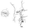
- FIG. 1is a partial view of the female reproductive system.
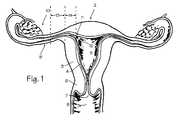
- FIG. 2is a drawing of the device used to deliver RF power and an occluding plug to the uterotubal junction.
- FIGS. 2 a and 2 bare close up views of the distal segment of the device including bipolar electrodes.
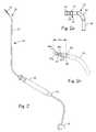
- FIG. 3is a drawing of the device with the distal section placed within the uterotubal junction before delivery of RF energy and detachment of the electrode (plug).
- FIGS. 3 a and 3 bare close-up views of the uterotubal junction before and after delivery of RF energy, illustrating detachment of the distal portion and removal of the remaining portions of the device.
- FIGS. 4-7describe various electrode designs for use with the device.
- FIG. 8is a side view of a coil shaped distal electrode.
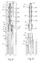
- FIG. 9is a cross section of the delivery catheter.
- FIG. 10is a cross section of the electrode plug assembly disconnected from the transcervical catheter.
- FIG. 11is a cross section of the occlusion device which uses laser energy and a laser tip to occlude the fallopian tube.
- FIG. 12illustrates an embodiment of the catheter which uses ultrasound energy to occlude the fallopian tube.
- FIG. 13illustrates an embodiment of the catheter which uses cryogenic energy to occlude the fallopian tube.
- FIG. 14is an overview of the female body illustrating major aspects of the sterilization method.
- FIG. 1shows some of the major elements of the female reproductive system.
- the uterus 2is an organ of the female pelvis that has the shape of a pear. It consists of a thick muscular coat, the myometrium 3 , a cavity having an inner mucosal lining of variable thickness called the endometrium 4 , and a cavity referred to as the uterine cavity 5 .
- the cervix 6defines the cervical canal 7 which is an inferior opening to the vagina 8 .
- the fallopian tube 9is a hollow organ that connects the uterus to the ovary 10 .
- the ovaryis the organ that produces one or more eggs during every cycle of a woman's reproductive life.
- the uterotubal junction 11In the human female reproductive system, there is one uterus, two fallopian tubes and two ovaries (under normal conditions).
- the site where the fallopian tube and uterus connectis called the uterotubal junction 11 .
- Itis a section of tubular shape of about 10 mm in length. Its inner diameter in the resting position is less than 1 mm, but when gas or liquid is pushed through the uterus and tubes, the diameter of the uterotubal junction may stretch up to about 2 mm.
- the uterotubal junctionprovides a transition between the uterus and the fallopian tube, and the area of transition from the chamber of the uterus to the lumen of the uterotubal junction is referred to as the ostium or cornu (marked with item number 12 ).
- the area of transition between the ostium and the isthmus 13 of the fallopian tubeis referred to as the interstitial portion (marked as item 14 ).
- the ostium, uterotubal junction, interstitial portion, isthmus and fallopian tubeare part of a pathway leading from the ovaries to the uterus, and this pathway is sometimes referred to as the uterine tube.
- FIG. 2shows the main components of the present invention.
- the firstis an elongated tubular segment, better known as a catheter 20 , that contains several significant components.
- the proximal section of the cathetercontains an electrical connector 21 to connect to an RF generator.
- a deflection handle 22located at the proximal section of the catheter.
- the distal section 23 of the catheterbends in a relative direction by means of a manipulation wire connected between the handle and distal catheter section.
- the actuator means on the handleBy operating the actuator means on the handle, the distal tip bends 30 to 180 degrees from straight.
- the detachable electrode plug 24is mounted on the catheter at the distal end of the catheter, and the proximal actuator 25 is mounted on the handle and connected to a detachment mechanism within the distal tip of the catheter.
- the middle section of the catheter 26(body), consists of a hollow tubular structure that contains the conductor(s), sensor wires, manipulation device and distal section anchor/release mechanism. This section protects the human body from these components and is required to deliver the distal tip portion to the proper location.
- the middle sectioncan be manufactured with stainless steel wire braid or winding to improve torque transfer. Improved torque transfer helps assist the doctor with twisting the handle on the proximal end of the device allowing for the torque to transfer to the distal section of the device and aid in proper placement of the distal section to the uterotubal junction.
- a coatingcan be applied to the shaft to increase its radiopacity for X-ray procedures.
- the coatingmay include compounds such as a barium sulfate loaded urethane or PebaxTM manufactured by Atochem.
- an echogenic coatingcan be applied to the shaft to increase the catheter's visibility during ultrasound imaging. This coating can include trapped air bubbles that provide an echogenic effect.
- the catheter shaftmay be made with a material loaded with air bubbles as well.
- Catheter shaft materialscan be, but are not limited to PTFE sold under the tradename of Teflon® manufactured by DuPont, ETFE, polyethylene, polypropylene and polyvinylchloride.
- FIG. 2 ashows a simple bipolar embodiment for the detachable electrodes on the distal section 23 of the catheter.
- the electrode plug 24contains the proximal electrode 27 , distal electrode 28 , and the insulator 29 to electrically and thermally insulate the electrodes, the anchor/release mechanism 30 for the electrode and a temperature sensor. It also contains a soft catheter portion 34 to allow deflection when the proximal handle is manipulated.
- One conductor wireis attached to the distal electrode and a second conductor wire is attached to the proximal electrode.
- the length of the conductorsis contained within the catheter body to isolate it from the patient.
- the conductorsare coated with an electrically insulative material.
- the proximal end of each conductoris attached to the electrical connector 21 .
- the electrical connectoris then connected to an RF generator.
- FIG. 2 billustrates another embodiment for the bipolar electrode plug 24 .
- the electrode assemblyincludes two hot electrodes 35 d and 35 p , and two ground electrodes 36 d and 36 p mounted on the insertion portion 37 of the electrode plug 24 .
- the insertion portioncomprises the insulator 29 and the electrodes.
- the attachment mechanism 30attaches to the soft catheter portion 34 , and is housed within the proximal section of the electrode plug 24 .
- the proximal section of the plugmay be provided with a larger diameter cross section than the insertion portion, in order to form a shoulder or flange type surface 38 which will serve to limit insertion of the plug and prevent insertion into the fallopian tubes.
- the distal electrodescan be made from any electrically conductive material such as stainless steel, copper, ElgiloyTM, MP35N, platinum, titanium, nitinol and various other materials and alloys.
- the surface of the distal electrodecan be covered or finished with a porous design to encourage fibroblast and/or tissue ingrowth. Tissue ingrowth (possibly referred to as scar formation) around the electrode insures a permanent seal of the fallopian tube.
- tissue ingrowthpossibly referred to as scar formation
- Different shape configurations and undercutscan also be incorporated into the electrode design to insure a permanent seal of the fallopian tube.
- Various embodiments of bipolar and monopolar plugsmay be adapted for use. For a monopolar device, there is only one electrode on the distal section of the catheter.
- the insulator 29can be made from any of the thermal and electrically insulative engineering materials such as ceramic, polyetheretherketone, UltemTM manufactured by General Electric, phenolic, epoxy, PebaxTM and PTFE.
- the surface of the insulatorcan be covered or finished with a porous design to encourage fibroblast ingrowth.
- the insulatorcan be manufactured from porous expandable material such as Teflon. Use of expanded PTFE encourages tissue ingrowth and/or scar formation around the electrode insuring a permanent seal and preventing plug migration over time.
- the insulatormay be a coating applied over a conductive material.
- the insulatorcan also be made from any of the bioresorbable or bioerodible materials such as polyglycolic acid (PGA), polylactic acid (PLA), polydioxanone (PDS), or any combination of them.
- PGApolyglycolic acid
- PLApolylactic acid
- PDSpolydioxanone
- the insulator materialcan also be attached to the distal section of the plug to encourage tissue ingrowth and/or scar formation distally from the plug in the fallopian tube.
- the proximal electrode 27can be made from any electrically conductive material such as stainless steel, copper, ElgiloyTM, MP35N, platinum, titanium, or nitinol or other alloys.
- the proximal electrodecan be larger than the distal electrode. This creates a higher current density in the tissue adjacent to the distal electrode and insulator, so that collapse of the fallopian tube is more pronounced in the insulator and distal electrode portion.
- the distal portioncan also contain a temperature sensing device such as a thermocouple or thermistor.
- the sensoris connected for feedback to a control circuit that modulates RF power applied to the electrodes according to the signal received from the temperature sensor.
- the control circuitcompares the signal from the temperature sensor to a set value and modulates the RF power applied to the electrode in accordance with the set value.
- a predetermined temperature settingcan also be used to stop RF power delivery to the electrode. In this way over-heating of the uterotubal junction can be prevented and the possibility of bowel perforation minimized.
- the procedurecan be done under x-ray guidance, sonographically, hysteroscopically, or blindly.
- the procedurecan be done under general and local anesthesia or general anesthesia only or local anesthesia only, with the latter preferred.
- the deviceis inserted into the body non-invasively: through the vagina, through the cervix into the uterus. This device can be inserted into another device such as a hysteroscope already positioned across the cervix.
- the distal segmentBy manipulating the proximal handle, the distal segment can be deflected to assist in proper positioning of the distal electrode within the uterotubal junction or fallopian tube ostium or fallopian tube.
- Impedance measurementsare taken from the tip electrode(s) to assist with proper positioning.
- impedancewill increase when the electrode is positioned properly within the uterotubal junction. It has been shown that this rise in current resistance is due in part to the current path moving from the electrically conductive media into the relatively higher resistant tissue within the uterotubal junction.
- impedancewill decrease when the electrode is positioned properly within the uterotubal junction. It has been shown that this decrease in current resistance is due in part to the current path moving from the non-electrically conductive media into the relatively lower resistant tissue within the uterotubal junction.
- Impedance monitoringcan be accomplished through the electrode plug in the RF embodiments, and it can be accomplished with the addition of impedance sensing electrodes in the laser and ultrasound embodiments.
- the current devicecan deliver a local anesthesia to the uterotubal junction before the delivery of RF, laser or ultrasound energy. This will prevent any discomfort to the patient during the procedure. It can be delivered in a liquid, gel, paste or pill form directly to the site. It can also be loaded into the electrode(s), laser hot tip, or ultrasound heating element, or into other parts of the device such as the insulating portions of the RF electrode assembly.
- Temperature and/or impedance monitoringcan be used to control or terminate RF current delivery to the electrode.
- the control circuitcompares the signal from the temperature sensor to a set value and modulates the RF power applied to the electrode in accordance with the set value.
- a predetermined temperature settingcan also be used to stop RF power delivery to the electrode.
- the control circuitcompares the signal from the electrode(s) to a set value and modulates the RF power applied to the electrode(s) in accordance with the set value.
- a predetermined impedance settingcan also be used to stop RF power delivery to the electrode.
- FIGS. 3 through 3 billustrate the procedure.
- FIG. 3shows the uterus and the structures of FIG. 1 , including the uterus 2 , cervix 6 , vagina 8 , fallopian tubes 9 , uterotubal junction 11 , the interstitial portion 14 and the ostium 12 .
- the catheter 20has been inserted through the vagina and across the cervix to the area of the ostium.
- the electrode plug 24has been advanced into the uterotubal junction 11 , until the shoulder of the plug meets the junction and inhibits further insertion (the surgeon will feel increased resistance to advancement, and will be able to visually observe impact of the shoulder).
- FIG. 3 ashows the electrode plug 24 mounted on the catheter distal tip 23 and inserted into the uterotubal junction 11 before heating of the plug and surrounding tissue with RF energy.
- the surrounding tissue of the uterotubal junctionhas been thermally injured and has swollen around the plug and into the gaps between the electrodes.
- FIG. 3 billustrates the plug after separation of the plug from the remainder of the device.
- the electrode plug 24including the electrodes 36 d , 36 p , 35 d , and 35 p , and the insulator 29 , remain within the uterotubal junction.
- the surrounding tissuewill heal in this condition, essentially surrounding and encapsulating the electrode plug to create a mechanical lock on the plug.
- the electrode plugmay be made in other embodiments which permit detachment of the distal electrode section from the remainder of the plug.
- a distal electrode and insulatorremain in place while the remaining portion of the catheter, including the proximal electrodes, are removed from the body.
- the electrode(s) and insulatorare designed to encourage fibroblast ingrowth to create a hermetic seal and prevent electrode migration.
- FIGS. 4 a through 4 dillustrate various shapes for electrodes in the simplest embodiment of the device.
- FIG. 4 ais a cylindrical plug with a ball point 39 at the distal end of the plug.
- FIG. 4 bis a cylindrical plug with a bullet point 40 at the distal end of the plug.
- FIG. 4 cis a cylindrical plug with a flat cylinder top 41 at the distal end of the plug.
- FIG. 4 dis a frustoconical plug with the small end 42 at the proximal end of the plug (it can be reversed).
- FIGS. 5 a - 5 cillustrate embodiments of the electrode plug which provide for mechanical interlocking relationship between the shrunken uterotubal junction and the electrode.
- FIG. 4 ais a cylindrical plug with a ball point 39 at the distal end of the plug.
- FIG. 4 bis a cylindrical plug with a bullet point 40 at the distal end of the plug.
- FIG. 4 cis a
- FIG. 5 ashows a pawn shaped electrode.
- FIG. 5 bshows a barbell shaped electrode, with globular bells 43 on either end of the electrode plug, separated by the insulator portion 29 .
- FIG. 5 cillustrated a barbell shaped electrode with an additional bell 44 between the bells at either end.
- FIG. 5 dillustrates a multi-flanged electrode assembly, with several flanges 45 extending outwardly from the insulator portion 29 .
- FIGS. 6 a through 6 cillustrate various forms for the proximal end of the electrode plug, making up the proximal shoulder 38 .
- FIG. 6 aillustrates a simple flange 46 on the proximal end of the electrode assembly 24 , while FIG.
- FIG. 6 bshows a mushroom shaped flange 47
- FIG. 6 cillustrates a contoured flange 48 .
- These shapesmay be applied to the proximal end (the uteral side of the plug) in order to limit the insertion of the plug into the fallopian tube.
- FIG. 7shows a plug having a screw thread 49 outer contour.
- FIG. 8illustrates a coil-shape configuration of the distal electrode plug.
- the electrically conductive materialBy manufacturing the electrically conductive material into a wire or strip, it is possible to wind the material over the insulative material to form a coiled electrode.
- a bipolar coiled plugis made possible by incorporating two separate wires parallel to each other along the coiled length.
- FIG. 8includes a helical ground electrode 50 and a helical hot electrode 51 coiled in parallel about insulated plug 52 to form the entire plug assembly 53 .
- the winding pitch or angle between wire and the insulative material being wound oncan vary through the plug. By varying the pitch angle, it is possible to create different current density fields for the plug.
- the pitchcan vary from 0° (parallel to the plug's major axis) to 90° (perpendicular to the plug's major axis). In one embodiment, the pitch remains at 0° for the length of the plug and is not wound at all.
- FIGS. 9 and 10show cross sections of the delivery catheter with mechanism for delivering energy to the heating tip and disconnecting the tip from the remainder of the catheter.
- Transcervical catheter 20is shown housed within the working channel of a hysteroscope 54 .
- the distal tip 23 of the transcervical catheter 20houses the electrode assembly 24 .
- the electrode plug 24is a bipolar electrode plug, with a central bore 55 which receives the central conductor assembly 56 .
- the central conductor assemblycomprises the necessary wiring to carry energy to the electrode assembly.
- the electrode assemblyincludes a electrode plug 57 with a mating assembly 58 at its proximal end 59 .
- the proximal end of the plugis flared, with shoulders 38 , designed to ensure that the electrode is not inserted beyond the uterotubal junction.
- Ground electrodes 36 d and 36 p and hot electrodes 35 d and 35 pprovide bipolar RF energy to any tissue outside the plug.
- the electrodesare connected to the remainder of the catheter through electrical contacts 60 , and these contacts are further connected to ground wires and hot wires coiled onto the central conductor assembly 56 .
- the mating assembly 58includes a receiving bore 63 for receiving the central conductor assembly.
- the distal end of the transcervical catheterlikewise has a receiving bore 64 for receiving the spring loaded tangs or détentes 65 which are biased toward the center of the device, but held in radially expanded condition by the thickness of the central conductor assembly 56 .
- the tangs 65extend into matching receiving holes 66 in the distal end of the insertion catheter 20 .
- the electrical ground wires and hot wiresare connected to the RF generator which is outside the body, connected to the proximal end of the transcervical catheter.
- the hysteroscope and transcervical catheterare inserted into the uterus through the cervix.
- the physiciancan locate the ostium of the fallopian tube, which corresponds to the uterotubal junction.
- the physicianadvances the transcervical catheter out of the hysteroscope, and inserts the plug into the uterotubal junction until the shoulders of the plug are firmly seated in the uterotubal junction.
- Electrical energyis applied through one or more of the electrodes, grounded through the ground electrodes. When the uterotubal junction has been thermally damaged, it collapses and constricts about the electrode plug.
- the outer surface of the electrode plugis irregular, allowing mechanical interlock between the uterotubal junction and the plug when the plug constricts over the plug.
- the central conductor assembly 56is pulled proximally while the catheter 20 is held in place.
- the central conductor assembly 56is pulled distally to the point where it clears the tangs, the tangs resiliently rebound to the center of the catheter and fall out of the receiving holes 66 , as illustrated in FIG. 10 .
- the shoulder 67 on the transition of the central conductor assembly 56may be used to push gently on the electrode plug while gentle force is applied to the catheter.
- the deployed plugis left in place to provide permanent occlusion of the fallopian tube. (The process is repeated for each fallopian tube.)
- the RF energymay be supplied by any one of numerous RF energy generators available commercially. Although RF energy is currently preferred, microwave energy may also be used, and microwave energy generators suitable for use include such devices as the Prostatron microwave generator currently used for application of microwave energy to the prostate. Microwave power in the frequency of about 100 MHz to 14,000 MHz will also provide sufficient thermal damage to the fallopian tube to initiate collapse and constriction around the electrode.
- FIG. 11illustrates an embodiment of the catheter which uses laser light, rather than RF energy, to provide the heat necessary to thermally damage the fallopian tubes and cause them to constrict.
- the laser device shown in FIG. 11includes a laser light source (not shown), a central conductor 56 comprising fiber optic fiber 70 capable of delivering laser light from the laser source to the tip of the electrode, and a laser heating tip 71 disposed at the distal end of the catheter.
- the fiber optic fiberis releasably attached to the heating tip with a mechanism such as the releasable détentes described above.
- optical mechanismsmay include press fitting the fiber optic into a receiving bore in the heating tip so that it may be pulled out of the tip after heating, maintaining the tip in place with force from the catheter outer tube.
- the optical fibermay also be glued or melted into the tip, and simply snipped with endoscopic cutters after heating.
- laser light sourcesare commercially available for a variety of other purposes, and these may be readily adapted for use in supplying heating light for the fallopian tubes.
- the heating tip 71is a plug of silicone, bioglass or other transparent tip suitable for laser heating, and in this case it is cylindrical.
- the fiber opticis aimed at the proximal end of a necked down detente holding pin 73 , which is inserted into the receiving bore of the heating tip.
- the distal end of the fiber optic fiber and the distal end of the receiving boreare highly polished to permit maximum transmittance of laser light into the tip.
- a reflective surface 74is applied to the distal face of the tip to reflect laser light that reaches the distal face back into the plug.
- the plugis loaded with dispersive particles (silica, alumina or titania) which serve to disperse the laser energy throughout the plug and convert the energy into heat. When the plug is heated in this manner, it heats the surrounding uterotubal junction tissue to affect the thermal damage which is desirable in the sterilization method.
- Laser light sources and power ranges typically used for such applications of laser thermal treatmentare expected to be safe and sufficient for use in application to the uterotubal junction.
- FIG. 12illustrates an embodiment of the catheter which uses ultrasound energy, rather than RF energy, to provide the heat necessary to thermally damage the fallopian tubes and cause them to constrict.
- FIG. 12shows the tip of the device, including the plug 75 , the transcervical catheter 76 , the piezo-electric crystal 77 and electrical conductors 78 .
- the plugis connected to the catheter outer tube 72 of the catheter with a release mechanism similar to that shown in the earlier figures.
- the coupling element 79sonically couples the transducer to the plug, and also mechanically couples the transducer to the plug.
- the coupling elementalso includes a small diameter distal extension which fits into the bore of the plug during delivery and heating, and permits release of the tangs 65 when the central conductor is pulled proximally and the wide proximal portion 80 clears the tangs.
- Excitation of the piezoelectric crystal with electrical impulses delivered through the wireswill cause the plug 75 and surrounding tissue to heat up, thereby causing the thermal damage to the uterotubal junction desired to cause collapse around the plug.
- the plugcan be disconnected from the rest of the transcervical catheter and left in place. Ultrasound energy in the range of 10 KHz to 4 MHz may be applied to effect thermal damage.
- FIG. 13illustrates an embodiment of the catheter which uses cryogenic cooling, rather than heating, to provide the thermal damage necessary to cause the fallopian tubes to constrict.
- FIG. 13shows the tip of the device, including the detachable cryogenic plug 84 mounted on the tip of the transcervical catheter 20 .
- the detachable plugin this instance comprises the tip of a cryosurgical probe of the type that uses liquid nitrogen. Cooling of the plug is accomplished by cryogenic cooling of the jacket 85 which fits closely within the plug.
- the cryogen supply line 86communicates with the annular lumen 87 formed between the jacket 85 and the supply line.
- the supply lineincludes a port 88 at the distal tip, to distribute cryogenic fluid into the jacket.
- Liquid nitrogen or other cryogenis supplied to the probe through the supply line, and exhausts out the annular lumen and the gas return line 89 .
- the gas lineis pulled proximally until the jacket clears the tangs 65 of the release mechanism, at which point the tangs release the catheter 20 and the plug is left in place.
- Another embodiment of the deviceis one which accomplishes conductive and convective heating through the plug to accomplish the same results.
- conductive and convective techniquesFor example, AC or DC current can be delivered directly through the plug to create resistive heating of the plug which in turn generates a hot surface on the plug.
- Another possible techniqueis the delivery of a hot gas or hot liquid through channels of the catheter to the plug.
- a plugcould be designed with a resistive element placed with the plug to heat the plug and its surface. Heat would be transferred to the uterotubal junction by conduction and/or convection. Conduction of heat from the plug surface to the uterotubal junction is accomplished by placing the plug in direct contact with the uterotubal junction. Convection of heat from the plug surface to the uterotubal junction is accomplished by transfer of heat from the plug surface to fluids in the area of the plug such as body fluids or artificial liquids, and this fluid in turn transfers heat to the uterotubal junction
- FIG. 14illustrates the overall method of using the devices described in this patent.
- the patient 1lays on an operating table 90 , in position similar to that used for a gynecology exam, providing access to the vagina 8 .
- Access to the cervix 6 and uterus 2is facilitated by insertion and opening of the speculum 91 , which is locked to the operating table 90 with clamping mechanism 92 .
- the physicianinserts the hysteroscope 54 to find and inspect the opening into the fallopian tubes (called the ostium), and then inserts the transcervical catheter 20 and advances the transcervical catheter until the plug is seated in the ostium of the fallopian tube.
- the ostiumfallopian tubes
- the catheter locking mechanism 93(the illustrated locking mechanism is a set screw installed on the hysteroscope access port 94 ) to fix the transcervical catheter in place and prevent accidental removal of the plug during the procedure or during release of the plug.
- the speculum clamp and catheter locking mechanismform a locking jig which includes one clamp for fixing the scope to the operating table and a second clamp for securely holding the proximal end of the transcervical catheter.
- the physicianmay safely apply energy to the releasable tip without fear of inadvertently pulling the plug uterotubal junction and misapplying the required energy.
- the physicianthen applies energy sufficient to cause the uterotubal junction to collapse about the catheter tip. After collapse and constriction has been confirmed (this may be done visually through the hysteroscope, or by comparison of electrode impedance in the RF embodiments), the physician will hold the outer body of the transcervical catheter firmly and pull the central conductor from the plug.
- tissue responseImmediately after delivery of the RF energy to the targeted tissue, several stages of tissue response will occur in the healthy female.
- the damaged tissuewill undergo an acute inflammatory response.
- serum and white blood cellsexit from the blood vessels near the tissue and move into the interstitial space between the cells. This process is called edema.
- This processis accompanied by the release of products from the mast cells, which increase the vascular permeability to serum and white blood cells, increasing the edema.
- Giant cells called macrophagesthen move into the damaged tissue and start digesting the thermally damaged cells.
- the next stage of responseis the healing stage, in which repair mechanisms take place to restore the uterotubal junction to its original condition.
- cytokines and other products released by the mast cellsstimulate the fibroblasts of the conjunctive tissue (under the endosalpinx) which duplicate and migrate into the area of the destroyed tissue.
- the fibroblaststhen produce a matrix of gel like material and fibers in which the fibroblasts proliferate. This process is called colonization, and continues until the entire damaged area is filled with fibroblasts.
- the blood vessels in the injured areaform buds which grow into the new fibroblast matrix and revascularize the newly formed tissue.
- each of the plugs illustrated abovemay be made of a porous material (metal, glass, ceramic or other material) with pores ranging from about 1-400 microns.
- the poresmay be natural to the material, or they may be manufactured into the material. (For example, metal plugs with pores may be manufactured as reticulated or foamed metals according to known techniques.)
- Tissue in-growthcan be promoted by application of in-growth promoting compounds such P15 or HEP III to the porous plug.
- in-growth promoting compoundssuch as P15 or HEP III
- Such agentsthat promote either the attachment of cells to the plug or the cellular growth deep into the pores and surface features (nooks and crannies) of the plug.
- Such agentsinclude protein coatings such as collagen, fibronectin, and transforming growth factor beta, or a synthetic polypeptide coatings such as P15 (Gly-Thr-Pro-Gly-Pro-Gln-GLy-Ile-Ala-Gly-Gln-Arg-Gly-Val-Val) or HEP III (GLy-Glu-Phe-Tyr-Phe-Asp-Leu-Arg-Leu-Lys-Gly-Asp-Lys), The manufacture of these compounds is well described in Bhatnagar, Synthetic Compounds And Compositions With Enhanced Cell Binding, U.S. Pat. No. 5,635,482 (Jun.
- Coating of the device by these proteins or polypeptidescan be accomplished by dipping the plug into a solution or liquid suspension of the coating. This may be done immediately before implanting the plugs into the uterotubal junction, merely by dipping or glomming P15 suspension onto the plug.
- the coatingmay also be applied during manufacture using dipping and coating techniques commercially available from such companies as Peptide Innovations, Inc. of Southfield, Mich.
- the in-growth promoting compoundmay be injected to the vicinity of the plug after the plug has been implanted or before implantation. Although heat will be generated in the vicinity of the plug, the in-growth promoting compound is not damaged.
- the P15 compoundappears to permit direct attachment of new endothelial cells to the plug material, and the endothelial cells are further attached to the uterotubal junction, thus securing the plug in place.
- the compoundalso appears to encourage endothelial growth sufficient to create a matrix of endothelial cells which is mechanically intermingled with the porous structure of the plug.
Landscapes
- Health & Medical Sciences (AREA)
- Life Sciences & Earth Sciences (AREA)
- Surgery (AREA)
- Engineering & Computer Science (AREA)
- General Health & Medical Sciences (AREA)
- Biomedical Technology (AREA)
- Heart & Thoracic Surgery (AREA)
- Animal Behavior & Ethology (AREA)
- Public Health (AREA)
- Veterinary Medicine (AREA)
- Nuclear Medicine, Radiotherapy & Molecular Imaging (AREA)
- Vascular Medicine (AREA)
- Medical Informatics (AREA)
- Molecular Biology (AREA)
- Reproductive Health (AREA)
- Physics & Mathematics (AREA)
- Plasma & Fusion (AREA)
- Otolaryngology (AREA)
- Surgical Instruments (AREA)
- Materials For Medical Uses (AREA)
- Crystals, And After-Treatments Of Crystals (AREA)
- Dicing (AREA)
- Glass Compositions (AREA)
- Solid-Sorbent Or Filter-Aiding Compositions (AREA)
- Saccharide Compounds (AREA)
- Thermotherapy And Cooling Therapy Devices (AREA)
- Quick-Acting Or Multi-Walled Pipe Joints (AREA)
Abstract
Description
Claims (37)
Priority Applications (2)
| Application Number | Priority Date | Filing Date | Title |
|---|---|---|---|
| US11/752,222US7905880B2 (en) | 1997-06-05 | 2007-05-22 | Method and apparatus for tubal occlusion |
| US13/034,103US20110308527A1 (en) | 1997-06-05 | 2011-02-24 | Method and Apparatus for Tubal Occlusion |
Applications Claiming Priority (8)
| Application Number | Priority Date | Filing Date | Title |
|---|---|---|---|
| US4863297P | 1997-06-05 | 1997-06-05 | |
| US5438897P | 1997-07-31 | 1997-07-31 | |
| US09/063,119US5954715A (en) | 1997-06-05 | 1998-04-20 | Method and apparatus for tubal occlusion |
| US09/372,394US6068626A (en) | 1997-06-05 | 1999-08-10 | Method and apparatus for tubal occlusion |
| US09/579,976US6346102B1 (en) | 1997-06-05 | 2000-05-26 | Method and apparatus for tubal occlusion |
| US10/075,854US6726682B2 (en) | 1997-06-05 | 2002-02-12 | Method and apparatus for tubal occlusion |
| US10/832,909US7220259B2 (en) | 1997-06-05 | 2004-04-26 | Method and apparatus for tubal occlusion |
| US11/752,222US7905880B2 (en) | 1997-06-05 | 2007-05-22 | Method and apparatus for tubal occlusion |
Related Parent Applications (1)
| Application Number | Title | Priority Date | Filing Date |
|---|---|---|---|
| US10/832,909ContinuationUS7220259B2 (en) | 1997-06-05 | 2004-04-26 | Method and apparatus for tubal occlusion |
Related Child Applications (1)
| Application Number | Title | Priority Date | Filing Date |
|---|---|---|---|
| US13/034,103ContinuationUS20110308527A1 (en) | 1997-06-05 | 2011-02-24 | Method and Apparatus for Tubal Occlusion |
Publications (2)
| Publication Number | Publication Date |
|---|---|
| US20070215163A1 US20070215163A1 (en) | 2007-09-20 |
| US7905880B2true US7905880B2 (en) | 2011-03-15 |
Family
ID=26726348
Family Applications (7)
| Application Number | Title | Priority Date | Filing Date |
|---|---|---|---|
| US09/063,119Expired - LifetimeUS5954715A (en) | 1997-06-05 | 1998-04-20 | Method and apparatus for tubal occlusion |
| US09/372,394Expired - Fee RelatedUS6068626A (en) | 1997-06-05 | 1999-08-10 | Method and apparatus for tubal occlusion |
| US09/579,976Expired - LifetimeUS6346102B1 (en) | 1997-06-05 | 2000-05-26 | Method and apparatus for tubal occlusion |
| US10/075,854Expired - Fee RelatedUS6726682B2 (en) | 1997-06-05 | 2002-02-12 | Method and apparatus for tubal occlusion |
| US10/832,909Expired - Fee RelatedUS7220259B2 (en) | 1997-06-05 | 2004-04-26 | Method and apparatus for tubal occlusion |
| US11/752,222Expired - Fee RelatedUS7905880B2 (en) | 1997-06-05 | 2007-05-22 | Method and apparatus for tubal occlusion |
| US13/034,103AbandonedUS20110308527A1 (en) | 1997-06-05 | 2011-02-24 | Method and Apparatus for Tubal Occlusion |
Family Applications Before (5)
| Application Number | Title | Priority Date | Filing Date |
|---|---|---|---|
| US09/063,119Expired - LifetimeUS5954715A (en) | 1997-06-05 | 1998-04-20 | Method and apparatus for tubal occlusion |
| US09/372,394Expired - Fee RelatedUS6068626A (en) | 1997-06-05 | 1999-08-10 | Method and apparatus for tubal occlusion |
| US09/579,976Expired - LifetimeUS6346102B1 (en) | 1997-06-05 | 2000-05-26 | Method and apparatus for tubal occlusion |
| US10/075,854Expired - Fee RelatedUS6726682B2 (en) | 1997-06-05 | 2002-02-12 | Method and apparatus for tubal occlusion |
| US10/832,909Expired - Fee RelatedUS7220259B2 (en) | 1997-06-05 | 2004-04-26 | Method and apparatus for tubal occlusion |
Family Applications After (1)
| Application Number | Title | Priority Date | Filing Date |
|---|---|---|---|
| US13/034,103AbandonedUS20110308527A1 (en) | 1997-06-05 | 2011-02-24 | Method and Apparatus for Tubal Occlusion |
Country Status (8)
| Country | Link |
|---|---|
| US (7) | US5954715A (en) |
| EP (2) | EP1005296B8 (en) |
| AT (2) | ATE291889T1 (en) |
| AU (1) | AU758284B2 (en) |
| CA (1) | CA2311375C (en) |
| DE (2) | DE69829569T2 (en) |
| ES (1) | ES2238759T3 (en) |
| WO (1) | WO1998055046A1 (en) |
Cited By (6)
| Publication number | Priority date | Publication date | Assignee | Title |
|---|---|---|---|---|
| US20100063360A1 (en)* | 2006-11-28 | 2010-03-11 | Adiana, Inc. | Side-arm Port Introducer |
| US20110180073A1 (en)* | 2010-01-22 | 2011-07-28 | David Callaghan | Sterilization Device and Method |
| US8226645B2 (en) | 1999-02-01 | 2012-07-24 | Cytyc Corporation | Apparatus for tubal occlusion |
| WO2016007545A1 (en)* | 2014-07-07 | 2016-01-14 | Cirrus Technologies Kft | Systems and methods for female contraception |
| US20170128053A1 (en)* | 2014-03-28 | 2017-05-11 | Osaka University | Vagina evaluation device and uterus evaluation device |
| US11737911B2 (en) | 2014-11-24 | 2023-08-29 | Meditrina, Inc. | Systems and methods for permanent female contraception |
Families Citing this family (202)
| Publication number | Priority date | Publication date | Assignee | Title |
|---|---|---|---|---|
| US6033401A (en) | 1997-03-12 | 2000-03-07 | Advanced Closure Systems, Inc. | Vascular sealing device with microwave antenna |
| US6705323B1 (en) | 1995-06-07 | 2004-03-16 | Conceptus, Inc. | Contraceptive transcervical fallopian tube occlusion devices and methods |
| US6176240B1 (en) | 1995-06-07 | 2001-01-23 | Conceptus, Inc. | Contraceptive transcervical fallopian tube occlusion devices and their delivery |
| US7604633B2 (en) | 1996-04-12 | 2009-10-20 | Cytyc Corporation | Moisture transport system for contact electrocoagulation |
| US20030191496A1 (en)* | 1997-03-12 | 2003-10-09 | Neomend, Inc. | Vascular sealing device with microwave antenna |
| US5954715A (en)* | 1997-06-05 | 1999-09-21 | Adiana, Inc. | Method and apparatus for tubal occlusion |
| US6042590A (en)* | 1997-06-16 | 2000-03-28 | Novomedics, Llc | Apparatus and methods for fallopian tube occlusion |
| WO1999007297A1 (en)* | 1997-08-05 | 1999-02-18 | Trustees Of Dartmouth College | System and methods for fallopian tube occlusion |
| US6200312B1 (en)* | 1997-09-11 | 2001-03-13 | Vnus Medical Technologies, Inc. | Expandable vein ligator catheter having multiple electrode leads |
| US8551082B2 (en) | 1998-05-08 | 2013-10-08 | Cytyc Surgical Products | Radio-frequency generator for powering an ablation device |
| US7004962B2 (en)* | 1998-07-27 | 2006-02-28 | Schneider (Usa), Inc. | Neuroaneurysm occlusion and delivery device and method of using same |
| US8702727B1 (en) | 1999-02-01 | 2014-04-22 | Hologic, Inc. | Delivery catheter with implant ejection mechanism |
| US6306132B1 (en) | 1999-06-17 | 2001-10-23 | Vivant Medical | Modular biopsy and microwave ablation needle delivery apparatus adapted to in situ assembly and method of use |
| US6482145B1 (en) | 2000-02-14 | 2002-11-19 | Obtech Medical Ag | Hydraulic anal incontinence treatment |
| US6471635B1 (en) | 2000-02-10 | 2002-10-29 | Obtech Medical Ag | Anal incontinence disease treatment with controlled wireless energy supply |
| US6464628B1 (en) | 1999-08-12 | 2002-10-15 | Obtech Medical Ag | Mechanical anal incontinence |
| US6763833B1 (en) | 1999-08-23 | 2004-07-20 | Conceptus, Inc. | Insertion/deployment catheter system for intrafallopian contraception |
| US6709667B1 (en) | 1999-08-23 | 2004-03-23 | Conceptus, Inc. | Deployment actuation system for intrafallopian contraception |
| US6286510B1 (en)* | 1999-11-05 | 2001-09-11 | Terry L. Ray | Apparatus and method for preventing fluid transfer between an oviduct and a uterine cavity |
| CA2635435C (en) | 2000-02-10 | 2010-05-25 | Potencia Medical Ag | Controlled urinary incontinence treatment |
| ATE391468T1 (en) | 2000-02-10 | 2008-04-15 | Potencia Medical Ag | MECHANICAL DEVICE FOR IMPOTENCY TREATMENT |
| ATE416743T1 (en) | 2000-02-11 | 2008-12-15 | Potentica Ag | DEVICE WITH ENERGY CONVERSION MEANS FOR TREATING IMPOTENCY |
| US7442165B2 (en) | 2000-02-14 | 2008-10-28 | Obtech Medical Ag | Penile prosthesis |
| WO2001047440A2 (en) | 2000-02-14 | 2001-07-05 | Potencia Medical Ag | Male impotence prosthesis apparatus with wireless energy supply |
| WO2001095809A1 (en)* | 2000-06-14 | 2001-12-20 | Sterilis, Inc. | Suturing method and apparatus |
| US7789876B2 (en) | 2000-08-14 | 2010-09-07 | Tyco Healthcare Group, Lp | Method and apparatus for positioning a catheter relative to an anatomical junction |
| US6896682B1 (en) | 2000-11-14 | 2005-05-24 | Biomedical Engineering Solutions, Inc. | Method and system for internal ligation of tubular structures |
| US6550480B2 (en) | 2001-01-31 | 2003-04-22 | Numed/Tech Llc | Lumen occluders made from thermodynamic materials |
| US7418966B2 (en)* | 2001-10-22 | 2008-09-02 | O. R. Solutions, Inc. | Surgical drape and method of detecting fluid and leaks in thermal treatment system basins |
| US7128739B2 (en) | 2001-11-02 | 2006-10-31 | Vivant Medical, Inc. | High-strength microwave antenna assemblies and methods of use |
| US6878147B2 (en) | 2001-11-02 | 2005-04-12 | Vivant Medical, Inc. | High-strength microwave antenna assemblies |
| US6736822B2 (en) | 2002-02-20 | 2004-05-18 | Mcclellan Scott B. | Device and method for internal ligation of tubular structures |
| US7278430B2 (en)* | 2002-03-01 | 2007-10-09 | Arvik Enterprises, Llc | Blood vessel occlusion device |
| US6752767B2 (en) | 2002-04-16 | 2004-06-22 | Vivant Medical, Inc. | Localization element with energized tip |
| US7197363B2 (en) | 2002-04-16 | 2007-03-27 | Vivant Medical, Inc. | Microwave antenna having a curved configuration |
| US6780182B2 (en)* | 2002-05-23 | 2004-08-24 | Adiana, Inc. | Catheter placement detection system and operator interface |
| EP1562506B1 (en)* | 2002-11-15 | 2009-05-13 | C.R.Bard, Inc. | Electrophysiology catheter with ablation electrode |
| US7632291B2 (en)* | 2003-06-13 | 2009-12-15 | Trivascular2, Inc. | Inflatable implant |
| US7311703B2 (en) | 2003-07-18 | 2007-12-25 | Vivant Medical, Inc. | Devices and methods for cooling microwave antennas |
| US7258121B1 (en)* | 2003-08-26 | 2007-08-21 | Ray Terry L | Apparatus and method for preventing fluid transfer between an oviduct and a uterine cavity |
| US20050061329A1 (en)* | 2003-09-18 | 2005-03-24 | Conceptus, Inc. | Catheter for intrafallopian contraceptive delivery |
| US20050107867A1 (en)* | 2003-11-17 | 2005-05-19 | Taheri Syde A. | Temporary absorbable venous occlusive stent and superficial vein treatment method |
| US8052669B2 (en) | 2004-02-25 | 2011-11-08 | Femasys Inc. | Methods and devices for delivery of compositions to conduits |
| US8048101B2 (en) | 2004-02-25 | 2011-11-01 | Femasys Inc. | Methods and devices for conduit occlusion |
| US8048086B2 (en) | 2004-02-25 | 2011-11-01 | Femasys Inc. | Methods and devices for conduit occlusion |
| US9238127B2 (en) | 2004-02-25 | 2016-01-19 | Femasys Inc. | Methods and devices for delivering to conduit |
| DE102004010940B4 (en)* | 2004-03-05 | 2012-01-26 | Erbe Elektromedizin Gmbh | Neutral electrode for HF surgery |
| US6964274B1 (en) | 2004-06-07 | 2005-11-15 | Ethicon, Inc. | Tubal sterilization device having expanding electrodes and method for performing sterilization using the same |
| US7250050B2 (en)* | 2004-06-07 | 2007-07-31 | Ethicon, Inc. | Tubal sterilization device having sesquipolar electrodes and method for performing sterilization using the same |
| US20060040231A1 (en)* | 2004-07-02 | 2006-02-23 | Discus Dental Impressions, Inc. | Curing light capable of multiple wavelengths |
| US8167874B2 (en)* | 2004-07-19 | 2012-05-01 | Mayo Foundation For Medical Education | Assembly and kit for marking tubal ostia |
| US7824408B2 (en) | 2004-08-05 | 2010-11-02 | Tyco Healthcare Group, Lp | Methods and apparatus for coagulating and/or constricting hollow anatomical structures |
| JP5046931B2 (en)* | 2004-08-05 | 2012-10-10 | タイコ ヘルスケア グループ リミテッド パートナーシップ | Method and apparatus for coagulating and / or constricting hollow anatomical structures |
| US20070016272A1 (en) | 2004-09-27 | 2007-01-18 | Thompson Russell B | Systems and methods for treating a hollow anatomical structure |
| WO2006052940A2 (en)* | 2004-11-05 | 2006-05-18 | Asthmatx, Inc. | Medical device with procedure improvement features |
| EP1654991A1 (en)* | 2004-11-08 | 2006-05-10 | Inderbitzi, Rolf, Dr. med. | Screw for vascular occlusion |
| US7731712B2 (en)* | 2004-12-20 | 2010-06-08 | Cytyc Corporation | Method and system for transcervical tubal occlusion |
| CN102525591B (en) | 2005-01-25 | 2014-12-10 | 泰科医疗集团有限合伙公司 | Structures for permanent occlusion of a hollow anatomical structure |
| US8181653B2 (en) | 2005-02-15 | 2012-05-22 | Yale University | Intrauterine fallopian tube occlusion device |
| US8662081B2 (en) | 2005-02-15 | 2014-03-04 | Yale University | Intrauterine device |
| AU2006214368B2 (en)* | 2005-02-15 | 2011-05-26 | Yale University | Intrauterine fallopian tube occlusion device and method for use |
| US7625372B2 (en)* | 2005-02-23 | 2009-12-01 | Vnus Medical Technologies, Inc. | Methods and apparatus for coagulating and/or constricting hollow anatomical structures |
| US7674260B2 (en)* | 2005-04-28 | 2010-03-09 | Cytyc Corporation | Emergency hemostasis device utilizing energy |
| US7799019B2 (en) | 2005-05-10 | 2010-09-21 | Vivant Medical, Inc. | Reinforced high strength microwave antenna |
| US7803156B2 (en) | 2006-03-08 | 2010-09-28 | Aragon Surgical, Inc. | Method and apparatus for surgical electrocautery |
| US8728072B2 (en) | 2005-05-12 | 2014-05-20 | Aesculap Ag | Electrocautery method and apparatus |
| US8696662B2 (en) | 2005-05-12 | 2014-04-15 | Aesculap Ag | Electrocautery method and apparatus |
| US7942874B2 (en) | 2005-05-12 | 2011-05-17 | Aragon Surgical, Inc. | Apparatus for tissue cauterization |
| US9339323B2 (en) | 2005-05-12 | 2016-05-17 | Aesculap Ag | Electrocautery method and apparatus |
| US7918863B2 (en) | 2005-06-24 | 2011-04-05 | Conceptus, Inc. | Minimally invasive surgical stabilization devices and methods |
| US20070055326A1 (en)* | 2005-07-21 | 2007-03-08 | Farley Brian E | Method of treating a hollow anatomical structure with a thermal catheter |
| US20070023534A1 (en)* | 2005-07-22 | 2007-02-01 | Mingsheng Liu | Water-source heat pump control system and method |
| US20070185432A1 (en)* | 2005-09-19 | 2007-08-09 | Transport Pharmaceuticals, Inc. | Electrokinetic system and method for delivering methotrexate |
| US20070066934A1 (en)* | 2005-09-19 | 2007-03-22 | Transport Pharmaceuticals, Inc. | Electrokinetic delivery system and methods therefor |
| US20070135826A1 (en) | 2005-12-01 | 2007-06-14 | Steve Zaver | Method and apparatus for delivering an implant without bias to a left atrial appendage |
| US20070135879A1 (en) | 2005-12-08 | 2007-06-14 | Mcintyre Jon T | Cylindrical device for delivering energy to tissue |
| US20070208213A1 (en)* | 2006-02-03 | 2007-09-06 | Swann Susan E | Method and apparatus for in-vitro fertilization and tubal occlusion |
| US9017361B2 (en)* | 2006-04-20 | 2015-04-28 | Covidien Lp | Occlusive implant and methods for hollow anatomical structure |
| US8574229B2 (en) | 2006-05-02 | 2013-11-05 | Aesculap Ag | Surgical tool |
| US20070265613A1 (en)* | 2006-05-10 | 2007-11-15 | Edelstein Peter Seth | Method and apparatus for sealing tissue |
| US7975697B2 (en)* | 2006-05-11 | 2011-07-12 | Conceptus, Inc. | Methods and apparatus for occluding reproductive tracts to effect contraception |
| US10639452B2 (en)* | 2006-07-13 | 2020-05-05 | Best Medical International, Inc. | Echo-opaque urethral catheter |
| US7647930B2 (en)* | 2006-08-02 | 2010-01-19 | ProMed, Inc. | Fallopian tube occlusion devices and methods |
| CN100464725C (en)* | 2006-09-14 | 2009-03-04 | 傅正英 | reversible tubal IUD |
| US20080071269A1 (en)* | 2006-09-18 | 2008-03-20 | Cytyc Corporation | Curved Endoscopic Medical Device |
| US8486060B2 (en) | 2006-09-18 | 2013-07-16 | Cytyc Corporation | Power ramping during RF ablation |
| US8068921B2 (en) | 2006-09-29 | 2011-11-29 | Vivant Medical, Inc. | Microwave antenna assembly and method of using the same |
| US7763033B2 (en)* | 2006-10-18 | 2010-07-27 | Interlace Medical, Inc. | System and methods for preventing intravasation during intrauterine procedures |
| US8025656B2 (en)* | 2006-11-07 | 2011-09-27 | Hologic, Inc. | Methods, systems and devices for performing gynecological procedures |
| US9392935B2 (en) | 2006-11-07 | 2016-07-19 | Hologic, Inc. | Methods for performing a medical procedure |
| US20090036840A1 (en)* | 2006-11-22 | 2009-02-05 | Cytyc Corporation | Atraumatic ball tip and side wall opening |
| US7846160B2 (en) | 2006-12-21 | 2010-12-07 | Cytyc Corporation | Method and apparatus for sterilization |
| WO2008098203A1 (en)* | 2007-02-09 | 2008-08-14 | Boston Scientific Scimed, Inc. | Medical probe with echogenic and insulative properties |
| PL2124831T3 (en) | 2007-03-15 | 2017-03-31 | Ortho-Space Ltd. | Prosthetic devices |
| WO2008115922A1 (en) | 2007-03-19 | 2008-09-25 | Michael Brenzel | Methods and apparatus for occlusion of body lumens |
| US8951274B2 (en) | 2007-04-06 | 2015-02-10 | Hologic, Inc. | Methods of high rate, low profile tissue removal |
| US9259233B2 (en) | 2007-04-06 | 2016-02-16 | Hologic, Inc. | Method and device for distending a gynecological cavity |
| US9095366B2 (en) | 2007-04-06 | 2015-08-04 | Hologic, Inc. | Tissue cutter with differential hardness |
| WO2008124650A1 (en) | 2007-04-06 | 2008-10-16 | Interlace Medical, Inc. | Method, system and device for tissue removal |
| US7998139B2 (en)* | 2007-04-25 | 2011-08-16 | Vivant Medical, Inc. | Cooled helical antenna for microwave ablation |
| US8133242B1 (en) | 2007-04-27 | 2012-03-13 | Q-Tech Medical Incorporated | Image-guided extraluminal occlusion |
| US8353901B2 (en) | 2007-05-22 | 2013-01-15 | Vivant Medical, Inc. | Energy delivery conduits for use with electrosurgical devices |
| US9023024B2 (en) | 2007-06-20 | 2015-05-05 | Covidien Lp | Reflective power monitoring for microwave applications |
| US9113851B2 (en)* | 2007-08-23 | 2015-08-25 | Cook Biotech Incorporated | Fistula plugs and apparatuses and methods for fistula plug delivery |
| US8100129B2 (en)* | 2007-08-28 | 2012-01-24 | Conceptus, Inc. | Methods and devices for occluding an ovarian pathway |
| US8066755B2 (en) | 2007-09-26 | 2011-11-29 | Trivascular, Inc. | System and method of pivoted stent deployment |
| US8226701B2 (en) | 2007-09-26 | 2012-07-24 | Trivascular, Inc. | Stent and delivery system for deployment thereof |
| US8663309B2 (en) | 2007-09-26 | 2014-03-04 | Trivascular, Inc. | Asymmetric stent apparatus and method |
| SE532142C2 (en)* | 2007-09-28 | 2009-11-03 | Clinical Laserthermia Systems | Device for determining a thermal property of a tissue |
| US20090084386A1 (en)* | 2007-10-01 | 2009-04-02 | Mcclellan Annette M L | Tubal ligation |
| US10159557B2 (en) | 2007-10-04 | 2018-12-25 | Trivascular, Inc. | Modular vascular graft for low profile percutaneous delivery |
| US8992409B2 (en) | 2007-10-11 | 2015-03-31 | Peter Forsell | Method for controlling flow in a bodily organ |
| US8696543B2 (en) | 2007-10-11 | 2014-04-15 | Kirk Promotion Ltd. | Method for controlling flow of intestinal contents in a patient's intestines |
| ES2876250T3 (en) | 2007-10-11 | 2021-11-12 | Implantica Patent Ltd | Apparatus for controlling flow in a body organ |
| US8795153B2 (en) | 2007-10-11 | 2014-08-05 | Peter Forsell | Method for treating female sexual dysfunction |
| US10195325B2 (en)* | 2007-10-11 | 2019-02-05 | Peter Forsell | Method for controlling flow of sperms in a uterine tube |
| US20090125023A1 (en)* | 2007-11-13 | 2009-05-14 | Cytyc Corporation | Electrosurgical Instrument |
| US8328861B2 (en) | 2007-11-16 | 2012-12-11 | Trivascular, Inc. | Delivery system and method for bifurcated graft |
| US8083789B2 (en) | 2007-11-16 | 2011-12-27 | Trivascular, Inc. | Securement assembly and method for expandable endovascular device |
| US8292880B2 (en) | 2007-11-27 | 2012-10-23 | Vivant Medical, Inc. | Targeted cooling of deployable microwave antenna |
| WO2009073619A2 (en)* | 2007-11-30 | 2009-06-11 | New England Association Of Gynecologic Laparoscopists, Llp | Transcervical excision and removal of tissue |
| WO2009096851A1 (en)* | 2008-01-28 | 2009-08-06 | Milux Holding Sa | A drainage device comprising a filter cleaning device |
| MX2010008003A (en) | 2008-01-29 | 2010-09-24 | Milux Holding Sa | Apparatus for treating obesity. |
| US8870867B2 (en) | 2008-02-06 | 2014-10-28 | Aesculap Ag | Articulable electrosurgical instrument with a stabilizable articulation actuator |
| EP2837580B1 (en)* | 2008-08-29 | 2018-10-10 | PepsiCo, Inc. | Post-mix beverage system comprising a cartridge having two chambers |
| US9554826B2 (en) | 2008-10-03 | 2017-01-31 | Femasys, Inc. | Contrast agent injection system for sonographic imaging |
| US12171463B2 (en) | 2008-10-03 | 2024-12-24 | Femasys Inc. | Contrast agent generation and injection system for sonographic imaging |
| US10070888B2 (en) | 2008-10-03 | 2018-09-11 | Femasys, Inc. | Methods and devices for sonographic imaging |
| US8874215B2 (en) | 2008-10-10 | 2014-10-28 | Peter Forsell | System, an apparatus, and a method for treating a sexual dysfunctional female patient |
| EP3851076A1 (en) | 2008-10-10 | 2021-07-21 | MedicalTree Patent Ltd. | An improved artificial valve |
| US9750592B2 (en)* | 2008-10-10 | 2017-09-05 | Carsten Nils Gutt | Arrangement for implanting and method for implanting |
| WO2010042046A1 (en) | 2008-10-10 | 2010-04-15 | Milux Holding S.A. | Apparatus, system and operation method for the treatment of female sexual dysfunction |
| AU2009302955B2 (en) | 2008-10-10 | 2017-01-05 | Implantica Patent Ltd. | Fastening means for implantable medical control assembly |
| WO2010042011A1 (en) | 2008-10-10 | 2010-04-15 | Milux Holding Sa | Heart help device, system, and method |
| US20100094075A1 (en)* | 2008-10-10 | 2010-04-15 | Hologic Inc. | Expandable medical devices with reinforced elastomeric members and methods employing the same |
| WO2010042018A1 (en) | 2008-10-10 | 2010-04-15 | Milux Holding S.A. | Heart help device, system and method |
| GB0818852D0 (en)* | 2008-10-15 | 2008-11-19 | Everingham John S | Occlusive plug |
| US20100217250A1 (en)* | 2009-02-24 | 2010-08-26 | Sierra Surgical Technologies | Methods and systems for controlled thermal tissue |
| US11903602B2 (en) | 2009-04-29 | 2024-02-20 | Hologic, Inc. | Uterine fibroid tissue removal device |
| US9949812B2 (en) | 2009-07-17 | 2018-04-24 | Peter Forsell | Vaginal operation method for the treatment of anal incontinence in women |
| US10952836B2 (en) | 2009-07-17 | 2021-03-23 | Peter Forsell | Vaginal operation method for the treatment of urinary incontinence in women |
| US8573221B2 (en)* | 2009-10-02 | 2013-11-05 | Eastern Virginia Medical School | Cervical occluder |
| US20110146692A1 (en) | 2009-12-23 | 2011-06-23 | Hologic, Inc. | Implant Delivery Device |
| US9616246B2 (en)* | 2010-01-04 | 2017-04-11 | Covidien Lp | Apparatus and methods for treating hollow anatomical structures |
| ES2436516T3 (en) | 2010-02-04 | 2014-01-02 | Aesculap Ag | Laparoscopic radiofrequency surgical device |
| US8211121B1 (en) | 2010-03-06 | 2012-07-03 | Q-Tech Medical Incorporated | Methods and apparatus for image-guided extraluminal occlusion using clamping jaws |
| EP2547258B1 (en) | 2010-03-17 | 2015-08-05 | The Board of Trustees of the University of Illionis | Implantable biomedical devices on bioresorbable substrates |
| US8419727B2 (en) | 2010-03-26 | 2013-04-16 | Aesculap Ag | Impedance mediated power delivery for electrosurgery |
| US8827992B2 (en) | 2010-03-26 | 2014-09-09 | Aesculap Ag | Impedance mediated control of power delivery for electrosurgery |
| US8550086B2 (en) | 2010-05-04 | 2013-10-08 | Hologic, Inc. | Radiopaque implant |
| US9180039B2 (en) | 2010-08-16 | 2015-11-10 | Yale University | Intrauterine device |
| US9173698B2 (en) | 2010-09-17 | 2015-11-03 | Aesculap Ag | Electrosurgical tissue sealing augmented with a seal-enhancing composition |
| CN103209663B (en) | 2010-10-18 | 2016-08-10 | 碧奥塞普蒂夫股份有限公司 | For device or medicine are inserted endoceliac method and apparatus |
| US20120130272A1 (en) | 2010-11-19 | 2012-05-24 | Hologic, Inc. | Lumen occlusion detection |
| US20120203199A1 (en)* | 2010-11-30 | 2012-08-09 | Incumed, Llc | Method and apparatus for providing access to an internal body organ |
| US9655557B2 (en) | 2011-02-04 | 2017-05-23 | Minerva Surgical, Inc. | Methods and systems for evaluating the integrity of a uterine cavity |
| US8562623B2 (en) | 2011-02-09 | 2013-10-22 | ROSS ALAN McDONALD | Vaginal occlusion device |
| US8479742B2 (en) | 2011-02-28 | 2013-07-09 | Hologic, Inc. | Constant rate delivery device |
| US9987042B2 (en) | 2011-04-07 | 2018-06-05 | Jai Singh | General uterine manipulator and system |
| CN203647441U (en) | 2011-04-07 | 2014-06-18 | 基万·史蒂文·辛格 | Uterine Manipulator System |
| US20130197536A1 (en)* | 2011-04-07 | 2013-08-01 | Jai Singh | General uterine manipulator and system |
| US9138343B2 (en) | 2011-05-31 | 2015-09-22 | Bayer Healthcare Llc | Tip protector sleeve |
| US9339327B2 (en) | 2011-06-28 | 2016-05-17 | Aesculap Ag | Electrosurgical tissue dissecting device |
| WO2013005484A1 (en)* | 2011-07-07 | 2013-01-10 | 山科精器株式会社 | Bipolar needle-shaped microwave surgical instrument |
| US11311332B2 (en) | 2011-08-23 | 2022-04-26 | Magneto Thrombectomy Solutions Ltd. | Thrombectomy devices |
| US9289307B2 (en) | 2011-10-18 | 2016-03-22 | Ortho-Space Ltd. | Prosthetic devices and methods for using same |
| US9486243B2 (en)* | 2011-11-08 | 2016-11-08 | Covidien Lp | Systems and methods for treatment of premenstrual dysphoric disorders |
| KR101979354B1 (en) | 2011-12-01 | 2019-08-29 | 더 보오드 오브 트러스티스 오브 더 유니버시티 오브 일리노이즈 | Transient devices designed to undergo programmable transformations |
| US9950158B2 (en)* | 2011-12-21 | 2018-04-24 | Cardiac Pacemakers, Inc. | Directional features for implantable medical leads |
| GB201202935D0 (en)* | 2012-02-21 | 2012-04-04 | Everingham John S | Occlusive plug |
| US8992595B2 (en) | 2012-04-04 | 2015-03-31 | Trivascular, Inc. | Durable stent graft with tapered struts and stable delivery methods and devices |
| US9498363B2 (en) | 2012-04-06 | 2016-11-22 | Trivascular, Inc. | Delivery catheter for endovascular device |
| AU2013249076B2 (en) | 2012-04-20 | 2018-03-29 | Jai Singh | Repositionable medical instrument support systems, devices, and methods |
| EP2846710B1 (en)* | 2012-05-09 | 2016-07-13 | Boston Scientific Scimed, Inc. | Bushing arm deformation mechanism |
| KR101415900B1 (en) | 2012-05-18 | 2014-07-08 | 신경민 | Reiterating type bipolar electrode for high frequency thermotherapy |
| US9439712B2 (en) | 2012-07-12 | 2016-09-13 | Covidien Lp | Heat-distribution indicators, thermal zone indicators, electrosurgical systems including same and methods of directing energy to tissue using same |
| JP6336451B2 (en) | 2012-09-26 | 2018-06-06 | アエスキュラップ アーゲー | Tissue cutting and sealing device |
| US9662165B2 (en) | 2012-10-02 | 2017-05-30 | Covidien Lp | Device and method for heat-sensitive agent application |
| US9370392B2 (en) | 2012-10-02 | 2016-06-21 | Covidien Lp | Heat-sensitive optical probes |
| US20150366607A1 (en)* | 2014-06-24 | 2015-12-24 | Robin Bek | Systems and methods for performing endometrial ablation |
| US10548664B2 (en)* | 2015-03-16 | 2020-02-04 | Hermes Innovations, LLC | Systems and methods for permanent female contraception |
| GB2536714B (en) | 2015-03-27 | 2017-05-10 | Cook Medical Technologies Llc | Vessel ablation system with adjustable ablation terminal |
| EP3092981A1 (en)* | 2015-05-12 | 2016-11-16 | VasDeBlock medical ApS | Occlusion device for reversible occlusion of a biological tube |
| WO2017046647A1 (en) | 2015-09-18 | 2017-03-23 | Ortho-Space Ltd. | Intramedullary fixated subacromial spacers |
| US10925543B2 (en) | 2015-11-11 | 2021-02-23 | The Board Of Trustees Of The University Of Illinois | Bioresorbable silicon electronics for transient implants |
| KR101577654B1 (en) | 2015-11-16 | 2015-12-15 | (주)하스피케어 | High frequency thermo therapic apparatus for cervical neoplasia |
| US20170281982A1 (en)* | 2016-03-31 | 2017-10-05 | Family Health International | Methods and systems for generating an occlusion using ultrasound |
| US20180078749A1 (en)* | 2016-09-19 | 2018-03-22 | National Guard Health Affairs | Cannula with curved end |
| US20180153734A1 (en)* | 2016-12-06 | 2018-06-07 | The Trustees Of Dartmouth College | Implant and implantation tool adapted for occluding fallopian tubes of placental mammals |
| EP3573806A4 (en) | 2017-01-30 | 2019-12-11 | Ortho-Space Ltd. | Processing machine and methods for processing dip-molded articles |
| US12029475B2 (en) | 2017-03-22 | 2024-07-09 | Magneto Thrombectomy Solutions Ltd. | Thrombectomy using both electrostatic and suction forces |
| EP3713507B1 (en) | 2017-11-23 | 2023-08-02 | Magneto Thrombectomy Solutions Ltd. | Tubular thrombectomy devices |
| US11076982B2 (en)* | 2017-12-29 | 2021-08-03 | Gyrus Acmi, Inc. | Fallopian biocompatible plug with differently expandable portions |
| GB201806193D0 (en)* | 2018-04-16 | 2018-05-30 | Emblation Ltd | Microwave application for the uterine cervix |
| WO2019243992A1 (en)* | 2018-06-20 | 2019-12-26 | Magneto Thrombectomy Solutions Ltd. | Various thrombectomy devices |
| US12102303B2 (en)* | 2019-04-05 | 2024-10-01 | Gynetronics Ltd. | Method and apparatus for direct in-vivo, electrical and chemical monitoring and stimulation of the endometrial cavity |
| USD918402S1 (en)* | 2019-08-13 | 2021-05-04 | Bios Srl | Body orifice device |
| USD918401S1 (en)* | 2019-08-13 | 2021-05-04 | Bios Srl | Body orifice device |
| CA3159187A1 (en)* | 2019-11-01 | 2021-05-06 | Jordan ADDISON | System for use in sealing a portion of pleural layers together |
| EP4119080A1 (en) | 2021-07-12 | 2023-01-18 | Erbe Elektromedizin GmbH | Plasma probe and method of mounting the electrode |
| FR3136360A1 (en)* | 2022-06-10 | 2023-12-15 | Innopath | Gynecological medical device for definitive tubal sterilization using a curved radiofrequency applicator |
| US20240206959A1 (en)* | 2022-12-22 | 2024-06-27 | Trisalus Life Sciences, Inc. | Systems and methods for selectively inducing vasoconstriction to increase therapeutic uptake in tissue |
Citations (109)
| Publication number | Priority date | Publication date | Assignee | Title |
|---|---|---|---|---|
| US2102270A (en) | 1935-11-29 | 1937-12-14 | Mortimer N Hyams | Electrosurgical device |
| US3680542A (en) | 1970-05-11 | 1972-08-01 | Hugo S Cimber | Device for occlusion of an oviduct |
| US3805767A (en) | 1973-02-26 | 1974-04-23 | Erb Rene | Method and apparatus for non-surgical, reversible sterilization of females |
| US3840016A (en) | 1972-03-10 | 1974-10-08 | H Lindemann | Electrocoagulation-bougie for the intrauterine tube sterilization |
| US3858586A (en) | 1971-03-11 | 1975-01-07 | Martin Lessen | Surgical method and electrode therefor |
| US3858571A (en) | 1973-07-02 | 1975-01-07 | Arthur I Rudolph | Cornual plug |
| US3918431A (en) | 1974-01-11 | 1975-11-11 | Manfred Sinnreich | Fallopian tube obturating device |
| US3938527A (en) | 1973-07-04 | 1976-02-17 | Centre De Recherche Industrielle De Quebec | Instrument for laparoscopic tubal cauterization |
| US3949736A (en) | 1974-07-15 | 1976-04-13 | Vyvojova A Provozni Zakladna Vyzkumnych Ustavu | Circuit for automatically deriving and measuring relative voltages associated with impedance components of a biological object |
| US3953566A (en) | 1970-05-21 | 1976-04-27 | W. L. Gore & Associates, Inc. | Process for producing porous products |
| USRE29345E (en) | 1973-02-26 | 1977-08-09 | The Franklin Institute | Method and apparatus for non-surgical, reversible sterilization of females |
| US4052754A (en) | 1975-08-14 | 1977-10-11 | Homsy Charles A | Implantable structure |
| US4057063A (en) | 1975-04-11 | 1977-11-08 | U.S. Philips Corporation | Device for sterilization by transuterine tube coagulation |
| US4185618A (en) | 1976-01-05 | 1980-01-29 | Population Research, Inc. | Promotion of fibrous tissue growth in fallopian tubes for female sterilization |
| US4245643A (en) | 1979-08-15 | 1981-01-20 | Children's Hospital Medical Center | Method and apparatus for measuring the ohmic contact resistance of an electrode attached to body tissue |
| US4258721A (en) | 1978-01-26 | 1981-03-31 | Bernard Parent | Self-contained portable hysteroscope |
| US4311145A (en) | 1979-07-16 | 1982-01-19 | Neomed, Inc. | Disposable electrosurgical instrument |
| US4416660A (en) | 1975-07-09 | 1983-11-22 | Dafoe Charles A | Method of transvaginal sterilization |
| US4474179A (en) | 1981-05-20 | 1984-10-02 | F. L. Fischer Gmbh & Co. | Method and apparatus for the high frequency coagulation of protein for surgical purposes |
| US4509504A (en) | 1978-01-18 | 1985-04-09 | Medline Ab | Occlusion of body channels |
| US4523590A (en) | 1982-10-25 | 1985-06-18 | Wilfred Roth | Method and device for reversible sterilization in mammals |
| US4537186A (en) | 1982-05-17 | 1985-08-27 | Verschoof Karel J H | Contraceptive device |
| US4606336A (en)* | 1984-11-23 | 1986-08-19 | Zeluff James W | Method and apparatus for non-surgically sterilizing female reproductive organs |
| EP0105669B1 (en) | 1982-09-30 | 1987-01-07 | Beta Phase Inc. | Method of contraception and apparatus for carrying out such method |
| US4641634A (en) | 1985-05-07 | 1987-02-10 | Karl Storz | One-hand hysteroscope |
| US4700701A (en) | 1985-10-23 | 1987-10-20 | Montaldi David H | Sterilization method and apparatus |
| US4779611A (en) | 1987-02-24 | 1988-10-25 | Grooters Ronald K | Disposable surgical scope guide |
| US4788966A (en) | 1987-05-14 | 1988-12-06 | Inbae Yoon | Plug for use in a reversible sterilization procedure |
| EP0153190B1 (en) | 1984-02-20 | 1989-05-03 | Olympus Optical Co., Ltd. | Endoscopic ovum picker instruments |
| US4834091A (en) | 1987-04-10 | 1989-05-30 | Ott Douglas E | Intrauterine fallopian tube ostial plug and surgical process |
| DE3917179A1 (en) | 1988-06-08 | 1989-12-21 | Messgeraetewerk Zwonitz Veb K | Catheter system for cardiological diagnosis |
| US4907158A (en) | 1987-05-29 | 1990-03-06 | Carl-Zeiss-Stiftung | Method for performing work on cells of a cell culture and apparatus therefor |
| US4966597A (en) | 1988-11-04 | 1990-10-30 | Cosman Eric R | Thermometric cardiac tissue ablation electrode with ultra-sensitive temperature detection |
| US4994069A (en) | 1988-11-02 | 1991-02-19 | Target Therapeutics | Vaso-occlusion coil and method |
| US5009655A (en) | 1989-05-24 | 1991-04-23 | C. R. Bard, Inc. | Hot tip device with optical diagnostic capability |
| US5095917A (en)* | 1990-01-19 | 1992-03-17 | Vancaillie Thierry G | Transuterine sterilization apparatus and method |
| US5122137A (en) | 1990-04-27 | 1992-06-16 | Boston Scientific Corporation | Temperature controlled rf coagulation |
| US5147353A (en) | 1990-03-23 | 1992-09-15 | Myriadlase, Inc. | Medical method for applying high energy light and heat for gynecological sterilization procedures |
| US5152784A (en) | 1989-12-14 | 1992-10-06 | Regents Of The University Of Minnesota | Prosthetic devices coated with a polypeptide with type IV collagen activity |
| US5167658A (en) | 1991-01-31 | 1992-12-01 | Mdt Corporation | Method and apparatus for electrosurgical measurement |
| US5203344A (en) | 1991-01-31 | 1993-04-20 | Brigham And Women's Hospital | Method and apparatus for taking bioelectrical impedance measurements using proximally positioned electrodes |
| US5304194A (en) | 1991-10-02 | 1994-04-19 | Target Therapeutics | Vasoocclusion coil with attached fibrous element(s) |
| US5303719A (en) | 1992-08-14 | 1994-04-19 | Wilk Peter J | Surgical method and associated instrument assembly |
| US5320091A (en) | 1992-04-27 | 1994-06-14 | Circon Corporation | Continuous flow hysteroscope |
| US5341807A (en) | 1992-06-30 | 1994-08-30 | American Cardiac Ablation Co., Inc. | Ablation catheter positioning system |
| US5366476A (en) | 1993-04-02 | 1994-11-22 | Laparomed Corporation | Handle for laparoscopic instrument |
| US5383922A (en) | 1993-03-15 | 1995-01-24 | Medtronic, Inc. | RF lead fixation and implantable lead |
| US5391146A (en) | 1993-06-24 | 1995-02-21 | Conceptus, Inc. | Mechanism for manipulating the distal end of a biomedical device |
| US5395342A (en) | 1990-07-26 | 1995-03-07 | Yoon; Inbae | Endoscopic portal |
| US5458640A (en) | 1993-01-29 | 1995-10-17 | Gerrone; Carmen J. | Cannula valve and seal system |
| US5460628A (en) | 1991-01-28 | 1995-10-24 | Neuwirth; Robert S. | Heated balloon medical apparatus with fluid agitating means |
| US5469857A (en) | 1993-03-12 | 1995-11-28 | Siemens Elema Ab | Apparatus for measuring electrical activity in the heart with graphical display of electrode contact with tissue |
| US5531741A (en) | 1994-08-18 | 1996-07-02 | Barbacci; Josephine A. | Illuminated stents |
| US5536267A (en) | 1993-11-08 | 1996-07-16 | Zomed International | Multiple electrode ablation apparatus |
| USRE35330E (en) | 1989-08-28 | 1996-09-17 | University Of Kansas Medical Center | Hot tip catheter assembly |
| US5556396A (en) | 1994-01-18 | 1996-09-17 | Endovascular, Inc. | Method for tubal electroligation |
| US5569242A (en) | 1994-05-06 | 1996-10-29 | Lax; Ronald G. | Method and apparatus for controlled contraction of soft tissue |
| US5569462A (en) | 1993-09-24 | 1996-10-29 | Baxter International Inc. | Methods for enhancing vascularization of implant devices |
| US5569245A (en) | 1990-03-13 | 1996-10-29 | The Regents Of The University Of California | Detachable endovascular occlusion device activated by alternating electric current |
| US5581487A (en) | 1994-02-23 | 1996-12-03 | Science Applications International Corporation | Method and apparatus for microscopic screening of cytological samples |
| EP0541258B1 (en) | 1991-11-06 | 1996-12-27 | Imagyn Medical, Inc. | Controller for manipulation of instruments within a catheter |
| US5589176A (en) | 1991-10-18 | 1996-12-31 | Seare, Jr.; William J. | Methods of making doubly porous device |
| EP0752236A1 (en) | 1995-07-07 | 1997-01-08 | Target Therapeutics, Inc. | Endoluminar electro occlusion device |
| US5601600A (en) | 1995-09-08 | 1997-02-11 | Conceptus, Inc. | Endoluminal coil delivery system having a mechanical release mechanism |
| US5617319A (en) | 1992-02-18 | 1997-04-01 | Pioneer Electronic Corporation | Navigation apparatus with enhanced positional display function |
| US5632767A (en) | 1994-09-09 | 1997-05-27 | Rare Earth Medical, Inc. | Loop diffusers for diffusion of optical radiation |
| US5635482A (en) | 1989-08-14 | 1997-06-03 | The Regents Of The University Of California | Synthetic compounds and compositions with enhanced cell binding |
| US5643253A (en) | 1995-06-06 | 1997-07-01 | Rare Earth Medical, Inc. | Phototherapy apparatus with integral stopper device |
| US5643257A (en) | 1994-01-18 | 1997-07-01 | Endovascular, Inc. | Apparatus and method for venous ligation |
| US5649924A (en) | 1988-06-10 | 1997-07-22 | Trimedyne, Inc. | Medical device for irradiation of tissue |
| US5658282A (en) | 1994-01-18 | 1997-08-19 | Endovascular, Inc. | Apparatus for in situ saphenous vein bypass and less-invasive varicose vein treatment |
| US5673704A (en) | 1994-01-28 | 1997-10-07 | Marchlinski; Francis E. | Method of using endocardial impedance for determining electrode-tissue contact |
| US5785705A (en) | 1994-10-11 | 1998-07-28 | Oratec Interventions, Inc. | RF method for controlled depth ablation of soft tissue |
| US5785706A (en) | 1996-11-18 | 1998-07-28 | Daig Corporation | Nonsurgical mapping and treatment of cardiac arrhythmia using a catheter contained within a guiding introducer containing openings |
| US5800529A (en) | 1990-10-31 | 1998-09-01 | Baxter International, Inc. | Close vascularization implant material |
| US5810810A (en) | 1992-04-23 | 1998-09-22 | Scimed Life Systems, Inc. | Apparatus and method for sealing vascular punctures |
| US5827269A (en) | 1996-12-31 | 1998-10-27 | Gynecare, Inc. | Heated balloon having a reciprocating fluid agitator |
| US5830222A (en) | 1995-10-13 | 1998-11-03 | Transvascular, Inc. | Device, system and method for intersititial transvascular intervention |
| US5836990A (en) | 1997-09-19 | 1998-11-17 | Medtronic, Inc. | Method and apparatus for determining electrode/tissue contact |
| US5836875A (en) | 1995-10-06 | 1998-11-17 | Cordis Webster, Inc. | Split tip electrode catheter |
| US5891457A (en) | 1997-05-12 | 1999-04-06 | Neuwirth; Robert S. | Intrauterine chemical necrosing method, composition, and apparatus |
| US5935137A (en) | 1997-07-18 | 1999-08-10 | Gynecare, Inc. | Tubular fallopian sterilization device |
| US5954715A (en) | 1997-06-05 | 1999-09-21 | Adiana, Inc. | Method and apparatus for tubal occlusion |
| US5979446A (en) | 1998-10-22 | 1999-11-09 | Synergyn Technologies, Inc. | Removable fallopian tube plug and associated methods |
| US6042590A (en) | 1997-06-16 | 2000-03-28 | Novomedics, Llc | Apparatus and methods for fallopian tube occlusion |
| US6066139A (en) | 1996-05-14 | 2000-05-23 | Sherwood Services Ag | Apparatus and method for sterilization and embolization |
| US6071283A (en) | 1997-06-06 | 2000-06-06 | Medical Scientific, Inc. | Selectively coated electrosurgical instrument |
| US6080152A (en) | 1998-06-05 | 2000-06-27 | Medical Scientific, Inc. | Electrosurgical instrument |
| US6091995A (en) | 1996-11-08 | 2000-07-18 | Surx, Inc. | Devices, methods, and systems for shrinking tissues |
| US6096052A (en) | 1998-07-08 | 2000-08-01 | Ovion, Inc. | Occluding device and method of use |
| US6145505A (en) | 1995-06-07 | 2000-11-14 | Conceptus, Inc. | Electrically affixed transcervical fallopian tube occlusion devices |
| US6264653B1 (en) | 1999-09-24 | 2001-07-24 | C. R. Band, Inc. | System and method for gauging the amount of electrode-tissue contact using pulsed radio frequency energy |
| US6309384B1 (en) | 1999-02-01 | 2001-10-30 | Adiana, Inc. | Method and apparatus for tubal occlusion |
| US6391024B1 (en) | 1999-06-17 | 2002-05-21 | Cardiac Pacemakers, Inc. | RF ablation apparatus and method having electrode/tissue contact assessment scheme and electrocardiogram filtering |
| US6401719B1 (en) | 1997-09-11 | 2002-06-11 | Vnus Medical Technologies, Inc. | Method of ligating hollow anatomical structures |
| US6432116B1 (en) | 1996-12-18 | 2002-08-13 | Ovion, Inc. | Occluding device and method of use |
| US6526979B1 (en) | 1995-06-07 | 2003-03-04 | Conceptus, Inc. | Contraceptive transcervical fallopian tube occlusion devices and methods |
| US6569160B1 (en) | 2000-07-07 | 2003-05-27 | Biosense, Inc. | System and method for detecting electrode-tissue contact |
| US6595989B1 (en) | 1999-05-11 | 2003-07-22 | Atrionix, Inc. | Balloon anchor wire |
| US6637962B1 (en) | 2002-03-25 | 2003-10-28 | Colin Roche | Ergonomic writing instrument |
| US6682477B2 (en) | 2000-02-25 | 2004-01-27 | Richard Wolf Gmbh | Hysteroscope |
| US6709667B1 (en) | 1999-08-23 | 2004-03-23 | Conceptus, Inc. | Deployment actuation system for intrafallopian contraception |
| US6763833B1 (en) | 1999-08-23 | 2004-07-20 | Conceptus, Inc. | Insertion/deployment catheter system for intrafallopian contraception |
| US6780182B2 (en) | 2002-05-23 | 2004-08-24 | Adiana, Inc. | Catheter placement detection system and operator interface |
| US20040267308A1 (en) | 2003-06-04 | 2004-12-30 | Accessclosure, Inc. | Auto-retraction apparatus and methods for sealing a vascular puncture |
| US6964274B1 (en) | 2004-06-07 | 2005-11-15 | Ethicon, Inc. | Tubal sterilization device having expanding electrodes and method for performing sterilization using the same |
| US7195630B2 (en) | 2003-08-21 | 2007-03-27 | Ethicon, Inc. | Converting cutting and coagulating electrosurgical device and method |
| US20070196158A1 (en) | 2005-12-12 | 2007-08-23 | Pacific Writing Instruments, Inc. | Ergonomic device |
| EP1554999B1 (en) | 1999-08-23 | 2008-01-23 | Conceptus, Inc. | Deployment actuation system for intrafallopian contraception |
Family Cites Families (8)
| Publication number | Priority date | Publication date | Assignee | Title |
|---|---|---|---|---|
| US29345A (en)* | 1860-07-24 | Martin shirk | ||
| DE2309749B2 (en)* | 1973-02-27 | 1978-05-24 | Siegfried Dr.Med. Dipl.-Ing. Dipl.-Wirtsch.-Ing. Lehr | Electrode for medical purposes |
| JPH0720216A (en)* | 1993-06-30 | 1995-01-24 | Honda Motor Co Ltd | Battery remaining capacity estimation method |
| US5599346A (en)* | 1993-11-08 | 1997-02-04 | Zomed International, Inc. | RF treatment system |
| US5556696A (en)* | 1994-09-23 | 1996-09-17 | Pinkus; Fred J. | Stiffening material for headwear and the like |
| EP1561427B1 (en)* | 1995-06-07 | 2010-01-06 | Conceptus, Inc. | Catheter system for expandable contraceptive transcervical fallopian tube occlusion devices having mechanical fallopian tube attachment |
| US5685878A (en)* | 1995-11-13 | 1997-11-11 | C.R. Bard, Inc. | Snap fit distal assembly for an ablation catheter |
| AU3583397A (en)* | 1996-06-27 | 1998-01-14 | Hank H. Chen | Transcervical electroocclusive sterilization device |
- 1998
- 1998-04-20USUS09/063,119patent/US5954715A/ennot_activeExpired - Lifetime
- 1998-04-20WOPCT/US1998/008111patent/WO1998055046A1/enactiveIP Right Grant
- 1998-04-20DEDE69829569Tpatent/DE69829569T2/ennot_activeExpired - Lifetime
- 1998-04-20ESES98918580Tpatent/ES2238759T3/ennot_activeExpired - Lifetime
- 1998-04-20DEDE69842144Tpatent/DE69842144D1/ennot_activeExpired - Lifetime
- 1998-04-20EPEP98918580Apatent/EP1005296B8/ennot_activeExpired - Lifetime
- 1998-04-20EPEP05006806Apatent/EP1568325B1/ennot_activeExpired - Lifetime
- 1998-04-20AUAU71481/98Apatent/AU758284B2/ennot_activeCeased
- 1998-04-20CACA002311375Apatent/CA2311375C/ennot_activeExpired - Fee Related
- 1998-04-20ATAT98918580Tpatent/ATE291889T1/ennot_activeIP Right Cessation
- 1998-04-20ATAT05006806Tpatent/ATE499045T1/ennot_activeIP Right Cessation
- 1999
- 1999-08-10USUS09/372,394patent/US6068626A/ennot_activeExpired - Fee Related
- 2000
- 2000-05-26USUS09/579,976patent/US6346102B1/ennot_activeExpired - Lifetime
- 2002
- 2002-02-12USUS10/075,854patent/US6726682B2/ennot_activeExpired - Fee Related
- 2004
- 2004-04-26USUS10/832,909patent/US7220259B2/ennot_activeExpired - Fee Related
- 2007
- 2007-05-22USUS11/752,222patent/US7905880B2/ennot_activeExpired - Fee Related
- 2011
- 2011-02-24USUS13/034,103patent/US20110308527A1/ennot_activeAbandoned
Patent Citations (134)
| Publication number | Priority date | Publication date | Assignee | Title |
|---|---|---|---|---|
| US2102270A (en) | 1935-11-29 | 1937-12-14 | Mortimer N Hyams | Electrosurgical device |
| US3680542A (en) | 1970-05-11 | 1972-08-01 | Hugo S Cimber | Device for occlusion of an oviduct |
| US3953566A (en) | 1970-05-21 | 1976-04-27 | W. L. Gore & Associates, Inc. | Process for producing porous products |
| US3858586A (en) | 1971-03-11 | 1975-01-07 | Martin Lessen | Surgical method and electrode therefor |
| US3840016A (en) | 1972-03-10 | 1974-10-08 | H Lindemann | Electrocoagulation-bougie for the intrauterine tube sterilization |
| USRE29345E (en) | 1973-02-26 | 1977-08-09 | The Franklin Institute | Method and apparatus for non-surgical, reversible sterilization of females |
| US3805767A (en) | 1973-02-26 | 1974-04-23 | Erb Rene | Method and apparatus for non-surgical, reversible sterilization of females |
| US3858571A (en) | 1973-07-02 | 1975-01-07 | Arthur I Rudolph | Cornual plug |
| US3938527A (en) | 1973-07-04 | 1976-02-17 | Centre De Recherche Industrielle De Quebec | Instrument for laparoscopic tubal cauterization |
| US3918431A (en) | 1974-01-11 | 1975-11-11 | Manfred Sinnreich | Fallopian tube obturating device |
| US3949736A (en) | 1974-07-15 | 1976-04-13 | Vyvojova A Provozni Zakladna Vyzkumnych Ustavu | Circuit for automatically deriving and measuring relative voltages associated with impedance components of a biological object |
| US4057063A (en) | 1975-04-11 | 1977-11-08 | U.S. Philips Corporation | Device for sterilization by transuterine tube coagulation |
| US4416660A (en) | 1975-07-09 | 1983-11-22 | Dafoe Charles A | Method of transvaginal sterilization |
| US4052754A (en) | 1975-08-14 | 1977-10-11 | Homsy Charles A | Implantable structure |
| US4185618A (en) | 1976-01-05 | 1980-01-29 | Population Research, Inc. | Promotion of fibrous tissue growth in fallopian tubes for female sterilization |
| US4509504A (en) | 1978-01-18 | 1985-04-09 | Medline Ab | Occlusion of body channels |
| US4258721A (en) | 1978-01-26 | 1981-03-31 | Bernard Parent | Self-contained portable hysteroscope |
| US4311145A (en) | 1979-07-16 | 1982-01-19 | Neomed, Inc. | Disposable electrosurgical instrument |
| US4245643A (en) | 1979-08-15 | 1981-01-20 | Children's Hospital Medical Center | Method and apparatus for measuring the ohmic contact resistance of an electrode attached to body tissue |
| US4474179A (en) | 1981-05-20 | 1984-10-02 | F. L. Fischer Gmbh & Co. | Method and apparatus for the high frequency coagulation of protein for surgical purposes |
| US4537186A (en) | 1982-05-17 | 1985-08-27 | Verschoof Karel J H | Contraceptive device |
| EP0105669B1 (en) | 1982-09-30 | 1987-01-07 | Beta Phase Inc. | Method of contraception and apparatus for carrying out such method |
| US4523590A (en) | 1982-10-25 | 1985-06-18 | Wilfred Roth | Method and device for reversible sterilization in mammals |
| EP0153190B1 (en) | 1984-02-20 | 1989-05-03 | Olympus Optical Co., Ltd. | Endoscopic ovum picker instruments |
| US4606336A (en)* | 1984-11-23 | 1986-08-19 | Zeluff James W | Method and apparatus for non-surgically sterilizing female reproductive organs |
| US4641634A (en) | 1985-05-07 | 1987-02-10 | Karl Storz | One-hand hysteroscope |
| US4700701A (en) | 1985-10-23 | 1987-10-20 | Montaldi David H | Sterilization method and apparatus |
| US4779611A (en) | 1987-02-24 | 1988-10-25 | Grooters Ronald K | Disposable surgical scope guide |
| US4834091A (en) | 1987-04-10 | 1989-05-30 | Ott Douglas E | Intrauterine fallopian tube ostial plug and surgical process |
| US4788966A (en) | 1987-05-14 | 1988-12-06 | Inbae Yoon | Plug for use in a reversible sterilization procedure |
| US4907158A (en) | 1987-05-29 | 1990-03-06 | Carl-Zeiss-Stiftung | Method for performing work on cells of a cell culture and apparatus therefor |
| DE3917179A1 (en) | 1988-06-08 | 1989-12-21 | Messgeraetewerk Zwonitz Veb K | Catheter system for cardiological diagnosis |
| US5649924A (en) | 1988-06-10 | 1997-07-22 | Trimedyne, Inc. | Medical device for irradiation of tissue |
| US4994069A (en) | 1988-11-02 | 1991-02-19 | Target Therapeutics | Vaso-occlusion coil and method |
| US4966597A (en) | 1988-11-04 | 1990-10-30 | Cosman Eric R | Thermometric cardiac tissue ablation electrode with ultra-sensitive temperature detection |
| US5009655A (en) | 1989-05-24 | 1991-04-23 | C. R. Bard, Inc. | Hot tip device with optical diagnostic capability |
| US5635482A (en) | 1989-08-14 | 1997-06-03 | The Regents Of The University Of California | Synthetic compounds and compositions with enhanced cell binding |
| USRE35330E (en) | 1989-08-28 | 1996-09-17 | University Of Kansas Medical Center | Hot tip catheter assembly |
| US5152784A (en) | 1989-12-14 | 1992-10-06 | Regents Of The University Of Minnesota | Prosthetic devices coated with a polypeptide with type IV collagen activity |
| US5095917A (en)* | 1990-01-19 | 1992-03-17 | Vancaillie Thierry G | Transuterine sterilization apparatus and method |
| US5569245A (en) | 1990-03-13 | 1996-10-29 | The Regents Of The University Of California | Detachable endovascular occlusion device activated by alternating electric current |
| US5147353A (en) | 1990-03-23 | 1992-09-15 | Myriadlase, Inc. | Medical method for applying high energy light and heat for gynecological sterilization procedures |
| US5122137A (en) | 1990-04-27 | 1992-06-16 | Boston Scientific Corporation | Temperature controlled rf coagulation |
| US5395342A (en) | 1990-07-26 | 1995-03-07 | Yoon; Inbae | Endoscopic portal |
| US5800529A (en) | 1990-10-31 | 1998-09-01 | Baxter International, Inc. | Close vascularization implant material |
| US5460628A (en) | 1991-01-28 | 1995-10-24 | Neuwirth; Robert S. | Heated balloon medical apparatus with fluid agitating means |
| US5203344A (en) | 1991-01-31 | 1993-04-20 | Brigham And Women's Hospital | Method and apparatus for taking bioelectrical impedance measurements using proximally positioned electrodes |
| US5167658A (en) | 1991-01-31 | 1992-12-01 | Mdt Corporation | Method and apparatus for electrosurgical measurement |
| US5304194A (en) | 1991-10-02 | 1994-04-19 | Target Therapeutics | Vasoocclusion coil with attached fibrous element(s) |
| US5605693A (en) | 1991-10-18 | 1997-02-25 | Seare, Jr.; William J. | Methods of making a porous device |
| US5589176A (en) | 1991-10-18 | 1996-12-31 | Seare, Jr.; William J. | Methods of making doubly porous device |
| EP0541258B1 (en) | 1991-11-06 | 1996-12-27 | Imagyn Medical, Inc. | Controller for manipulation of instruments within a catheter |
| US5617319A (en) | 1992-02-18 | 1997-04-01 | Pioneer Electronic Corporation | Navigation apparatus with enhanced positional display function |
| US5810810A (en) | 1992-04-23 | 1998-09-22 | Scimed Life Systems, Inc. | Apparatus and method for sealing vascular punctures |
| US5320091A (en) | 1992-04-27 | 1994-06-14 | Circon Corporation | Continuous flow hysteroscope |
| US5341807A (en) | 1992-06-30 | 1994-08-30 | American Cardiac Ablation Co., Inc. | Ablation catheter positioning system |
| US5303719A (en) | 1992-08-14 | 1994-04-19 | Wilk Peter J | Surgical method and associated instrument assembly |
| US5458640A (en) | 1993-01-29 | 1995-10-17 | Gerrone; Carmen J. | Cannula valve and seal system |
| US5469857A (en) | 1993-03-12 | 1995-11-28 | Siemens Elema Ab | Apparatus for measuring electrical activity in the heart with graphical display of electrode contact with tissue |
| US5383922A (en) | 1993-03-15 | 1995-01-24 | Medtronic, Inc. | RF lead fixation and implantable lead |
| US5366476A (en) | 1993-04-02 | 1994-11-22 | Laparomed Corporation | Handle for laparoscopic instrument |
| US5391146A (en) | 1993-06-24 | 1995-02-21 | Conceptus, Inc. | Mechanism for manipulating the distal end of a biomedical device |
| US5569462A (en) | 1993-09-24 | 1996-10-29 | Baxter International Inc. | Methods for enhancing vascularization of implant devices |
| US5536267A (en) | 1993-11-08 | 1996-07-16 | Zomed International | Multiple electrode ablation apparatus |
| US5643257A (en) | 1994-01-18 | 1997-07-01 | Endovascular, Inc. | Apparatus and method for venous ligation |
| US5556396A (en) | 1994-01-18 | 1996-09-17 | Endovascular, Inc. | Method for tubal electroligation |
| US5658282A (en) | 1994-01-18 | 1997-08-19 | Endovascular, Inc. | Apparatus for in situ saphenous vein bypass and less-invasive varicose vein treatment |
| US5673704A (en) | 1994-01-28 | 1997-10-07 | Marchlinski; Francis E. | Method of using endocardial impedance for determining electrode-tissue contact |
| US5581487A (en) | 1994-02-23 | 1996-12-03 | Science Applications International Corporation | Method and apparatus for microscopic screening of cytological samples |
| US5569242A (en) | 1994-05-06 | 1996-10-29 | Lax; Ronald G. | Method and apparatus for controlled contraction of soft tissue |
| US5531741A (en) | 1994-08-18 | 1996-07-02 | Barbacci; Josephine A. | Illuminated stents |
| US5632767A (en) | 1994-09-09 | 1997-05-27 | Rare Earth Medical, Inc. | Loop diffusers for diffusion of optical radiation |
| US5785705A (en) | 1994-10-11 | 1998-07-28 | Oratec Interventions, Inc. | RF method for controlled depth ablation of soft tissue |
| US5643253A (en) | 1995-06-06 | 1997-07-01 | Rare Earth Medical, Inc. | Phototherapy apparatus with integral stopper device |
| US6684884B2 (en) | 1995-06-07 | 2004-02-03 | Conceptus, Inc. | Contraceptive transcervical fallopian tube occlusion devices and methods |
| US6705323B1 (en) | 1995-06-07 | 2004-03-16 | Conceptus, Inc. | Contraceptive transcervical fallopian tube occlusion devices and methods |
| US7428904B2 (en) | 1995-06-07 | 2008-09-30 | Alien Technology Corporation | Contraceptive transcervical fallopian tube occlusion devices and their delivery |
| US6145505A (en) | 1995-06-07 | 2000-11-14 | Conceptus, Inc. | Electrically affixed transcervical fallopian tube occlusion devices |
| US6871650B1 (en) | 1995-06-07 | 2005-03-29 | Conceptus, Inc. | Contraceptive transcervical fallopian tube occlusion devices and their delivery |
| US6679266B2 (en) | 1995-06-07 | 2004-01-20 | Conceptus, Inc. | Contraceptive transcervical fallopian tube occlusion devices and their delivery |
| US6634361B1 (en) | 1995-06-07 | 2003-10-21 | Conceptus, Inc. | Contraceptive transcervical fallopian tube occlusion devices and methods |
| US6526979B1 (en) | 1995-06-07 | 2003-03-04 | Conceptus, Inc. | Contraceptive transcervical fallopian tube occlusion devices and methods |
| US6176240B1 (en) | 1995-06-07 | 2001-01-23 | Conceptus, Inc. | Contraceptive transcervical fallopian tube occlusion devices and their delivery |
| US5743905A (en) | 1995-07-07 | 1998-04-28 | Target Therapeutics, Inc. | Partially insulated occlusion device |
| CA2182738C (en) | 1995-07-07 | 2000-10-17 | Joseph C. Eder | Partially insulated occlusion device |
| EP0752236A1 (en) | 1995-07-07 | 1997-01-08 | Target Therapeutics, Inc. | Endoluminar electro occlusion device |
| EP0752236B1 (en) | 1995-07-07 | 2003-12-17 | Boston Scientific Limited | Endoluminar electro occlusion device |
| US5601600A (en) | 1995-09-08 | 1997-02-11 | Conceptus, Inc. | Endoluminal coil delivery system having a mechanical release mechanism |
| US5746769A (en) | 1995-09-08 | 1998-05-05 | Conceptus, Inc. | Endoluminal coil delivery system having a mechanical release mechanism |
| US5836875A (en) | 1995-10-06 | 1998-11-17 | Cordis Webster, Inc. | Split tip electrode catheter |
| US5830222A (en) | 1995-10-13 | 1998-11-03 | Transvascular, Inc. | Device, system and method for intersititial transvascular intervention |
| US6066139A (en) | 1996-05-14 | 2000-05-23 | Sherwood Services Ag | Apparatus and method for sterilization and embolization |
| US6091995A (en) | 1996-11-08 | 2000-07-18 | Surx, Inc. | Devices, methods, and systems for shrinking tissues |
| US5785706A (en) | 1996-11-18 | 1998-07-28 | Daig Corporation | Nonsurgical mapping and treatment of cardiac arrhythmia using a catheter contained within a guiding introducer containing openings |
| US7073504B2 (en) | 1996-12-18 | 2006-07-11 | Ams Research Corporation | Contraceptive system and method of use |
| US6432116B1 (en) | 1996-12-18 | 2002-08-13 | Ovion, Inc. | Occluding device and method of use |
| US7398780B2 (en) | 1996-12-18 | 2008-07-15 | Ams Research Corporation | Contraceptive system and method of use |
| US5827269A (en) | 1996-12-31 | 1998-10-27 | Gynecare, Inc. | Heated balloon having a reciprocating fluid agitator |
| US5891457A (en) | 1997-05-12 | 1999-04-06 | Neuwirth; Robert S. | Intrauterine chemical necrosing method, composition, and apparatus |
| US6726682B2 (en) | 1997-06-05 | 2004-04-27 | Adiana, Inc. | Method and apparatus for tubal occlusion |
| US6068626A (en) | 1997-06-05 | 2000-05-30 | Adiana, Inc. | Method and apparatus for tubal occlusion |
| US7220259B2 (en) | 1997-06-05 | 2007-05-22 | Adiana, Inc. | Method and apparatus for tubal occlusion |
| US6346102B1 (en) | 1997-06-05 | 2002-02-12 | Adiana, Inc. | Method and apparatus for tubal occlusion |
| US5954715A (en) | 1997-06-05 | 1999-09-21 | Adiana, Inc. | Method and apparatus for tubal occlusion |
| US6071283A (en) | 1997-06-06 | 2000-06-06 | Medical Scientific, Inc. | Selectively coated electrosurgical instrument |
| US6565557B1 (en) | 1997-06-16 | 2003-05-20 | Board Of Regents, The University Of Texas System | Apparatus and methods for fallopian tube occlusion |
| US6042590A (en) | 1997-06-16 | 2000-03-28 | Novomedics, Llc | Apparatus and methods for fallopian tube occlusion |
| US5935137A (en) | 1997-07-18 | 1999-08-10 | Gynecare, Inc. | Tubular fallopian sterilization device |
| US6401719B1 (en) | 1997-09-11 | 2002-06-11 | Vnus Medical Technologies, Inc. | Method of ligating hollow anatomical structures |
| US5836990A (en) | 1997-09-19 | 1998-11-17 | Medtronic, Inc. | Method and apparatus for determining electrode/tissue contact |
| US6080152A (en) | 1998-06-05 | 2000-06-27 | Medical Scientific, Inc. | Electrosurgical instrument |
| US6096052A (en) | 1998-07-08 | 2000-08-01 | Ovion, Inc. | Occluding device and method of use |
| US5979446A (en) | 1998-10-22 | 1999-11-09 | Synergyn Technologies, Inc. | Removable fallopian tube plug and associated methods |
| US6712810B2 (en) | 1999-02-01 | 2004-03-30 | Adiana, Inc. | Method and apparatus for tubal occlusion |
| US20040255958A1 (en) | 1999-02-01 | 2004-12-23 | Adiana, Inc. | Method and apparatus for tubal occlusion |
| US6309384B1 (en) | 1999-02-01 | 2001-10-30 | Adiana, Inc. | Method and apparatus for tubal occlusion |
| US6595989B1 (en) | 1999-05-11 | 2003-07-22 | Atrionix, Inc. | Balloon anchor wire |
| US6391024B1 (en) | 1999-06-17 | 2002-05-21 | Cardiac Pacemakers, Inc. | RF ablation apparatus and method having electrode/tissue contact assessment scheme and electrocardiogram filtering |
| US6709667B1 (en) | 1999-08-23 | 2004-03-23 | Conceptus, Inc. | Deployment actuation system for intrafallopian contraception |
| EP1554999B1 (en) | 1999-08-23 | 2008-01-23 | Conceptus, Inc. | Deployment actuation system for intrafallopian contraception |
| US7506650B2 (en) | 1999-08-23 | 2009-03-24 | Conceptus, Inc. | Deployment actuation system for intrafallopian contraception |
| US6763833B1 (en) | 1999-08-23 | 2004-07-20 | Conceptus, Inc. | Insertion/deployment catheter system for intrafallopian contraception |
| US7237552B2 (en) | 1999-08-23 | 2007-07-03 | Conceptus, Inc. | Insertion/deployment catheter system for intrafallopian contraception |
| US6264653B1 (en) | 1999-09-24 | 2001-07-24 | C. R. Band, Inc. | System and method for gauging the amount of electrode-tissue contact using pulsed radio frequency energy |
| GB2359492B (en) | 2000-02-25 | 2004-04-07 | Wolf Gmbh Richard | A hysteroscope |
| US6682477B2 (en) | 2000-02-25 | 2004-01-27 | Richard Wolf Gmbh | Hysteroscope |
| US6569160B1 (en) | 2000-07-07 | 2003-05-27 | Biosense, Inc. | System and method for detecting electrode-tissue contact |
| US6637962B1 (en) | 2002-03-25 | 2003-10-28 | Colin Roche | Ergonomic writing instrument |
| US6780182B2 (en) | 2002-05-23 | 2004-08-24 | Adiana, Inc. | Catheter placement detection system and operator interface |
| US7582085B2 (en) | 2002-05-23 | 2009-09-01 | Cytyc Corporation | Catheter placement detection system and operator interface |
| US20040267308A1 (en) | 2003-06-04 | 2004-12-30 | Accessclosure, Inc. | Auto-retraction apparatus and methods for sealing a vascular puncture |
| US7195630B2 (en) | 2003-08-21 | 2007-03-27 | Ethicon, Inc. | Converting cutting and coagulating electrosurgical device and method |
| US6964274B1 (en) | 2004-06-07 | 2005-11-15 | Ethicon, Inc. | Tubal sterilization device having expanding electrodes and method for performing sterilization using the same |
| US20070196158A1 (en) | 2005-12-12 | 2007-08-23 | Pacific Writing Instruments, Inc. | Ergonomic device |
Non-Patent Citations (17)
| Title |
|---|
| Brumsted, Attempted Transcervical Occlusion Of The Fallopian Tube With The ND: Yag Laser, 77 Obstetrics And Gynecology 327-28 (Feb. 1991). |
| Coleman, The Foreign Body Reaction: A Chronic Inflammatory Response, 8 J. Biomed. Mater. Res. 199-211 (1974). |
| Conceptus Incorporated, Summary of Safety and Effectiveness Data, P020014, Nov. 4, 2002. |
| Kearney, Patent Cooperation Treaty Written Opinion, International Application No. PCT/US98/08111, Date of Mailing Feb. 22, 1999. |
| Neuwirth, Update On Transcervical Sterilization, 51 International Journal Of Gynecology & Obstetrics, Suppl. 1, S23-28 (1995). |
| Office Action mailed Feb. 21, 2008, U.S. Appl. No. 10/812,476, filed Mar. 29, 2004 In Re: Douglas C. Harrington, "Method & Apparatus for Tubal Occlusion". |
| Office Action mailed Feb. 7, 2008, U.S. Appl. No. 10/924,584, filed Aug. 24, 2004 In Re: Brett S. Bowman, "Catheter Placement Detection System & Operator Interface". |
| Office Action mailed Jul. 31, 2007, U.S. Appl. No. 10/924,584, filed Aug. 24, 2004 In Re: Brett S. Bowman, "Catheter Placement Detection System & Operator Interface". |
| Office Action mailed Nov. 14, 2006, U.S. Appl. No. 10/924,584, filed Aug. 24, 2004 In Re: Brett S. Bowman, "Catheter Placement Detection System & Operator Interface". |
| Office Action mailed Oct. 10, 2006, U.S. Appl. No. 10/812,476, filed Mar. 29, 2004 In Re: Douglas C. Harrington, "Method & Apparatus for Tubal Occlusion". |
| Phillips, Experimental Closure Of Arteriovenous Fistula By Transcatheter Electrocoagulation, 115 Radiology 319-21 (May 1975). |
| Pollack, Wound Healing: A Review, 5:5 J. Dermatol. Surg. Oncol. 389 (May 1979). |
| Quinones Guerror, Tubal Electrocauterization Under Hysteroscopic Control, 7 Contraception 195-201 (Mar. 1973). |
| Quinones, Hysteroscopic Sterilization, 14 International Journal Of Gynecology & Obstetrics 27-34 (1976). |
| Sahwi, The Leukocytic Response to an Intrauterine Foreign Body in the Rabbit, 22 Fertility and Sterility 398 (Jun. 1971). |
| Thompson, Vessel Occlusion With Transcatheter Electrocoagulation: Initial Clinical Experience, 133 Radiology 335-340( Nov. 1979). |
| Tibbs, Wound Healing Following Radiation Therapy: A Review, 42 Radiology and Oncology 99-106 (1997). |
Cited By (12)
| Publication number | Priority date | Publication date | Assignee | Title |
|---|---|---|---|---|
| US8226645B2 (en) | 1999-02-01 | 2012-07-24 | Cytyc Corporation | Apparatus for tubal occlusion |
| US20100063360A1 (en)* | 2006-11-28 | 2010-03-11 | Adiana, Inc. | Side-arm Port Introducer |
| US20110180073A1 (en)* | 2010-01-22 | 2011-07-28 | David Callaghan | Sterilization Device and Method |
| US8231619B2 (en) | 2010-01-22 | 2012-07-31 | Cytyc Corporation | Sterilization device and method |
| US20170128053A1 (en)* | 2014-03-28 | 2017-05-11 | Osaka University | Vagina evaluation device and uterus evaluation device |
| US10271760B2 (en)* | 2014-03-28 | 2019-04-30 | Osaka University | Vagina evaluation device and uterus evaluation device |
| US10602955B2 (en) | 2014-03-28 | 2020-03-31 | Osaka University | Vagina evaluation device and uterus evaluation device |
| US11826131B2 (en) | 2014-03-28 | 2023-11-28 | Osaka University | Vagina evaluation device and uterus evaluation device |
| WO2016007545A1 (en)* | 2014-07-07 | 2016-01-14 | Cirrus Technologies Kft | Systems and methods for female contraception |
| US20160030109A1 (en)* | 2014-07-07 | 2016-02-04 | Cirrus Technologies Kft | Systems and methods for female contraception |
| US11871984B2 (en)* | 2014-07-07 | 2024-01-16 | Meditrina, Inc. | Systems and methods for female contraception |
| US11737911B2 (en) | 2014-11-24 | 2023-08-29 | Meditrina, Inc. | Systems and methods for permanent female contraception |
Also Published As
| Publication number | Publication date |
|---|---|
| US6346102B1 (en) | 2002-02-12 |
| US20020072744A1 (en) | 2002-06-13 |
| DE69842144D1 (en) | 2011-04-07 |
| EP1005296B1 (en) | 2005-03-30 |
| CA2311375A1 (en) | 1998-12-10 |
| DE69829569D1 (en) | 2005-05-04 |
| US5954715A (en) | 1999-09-21 |
| ATE499045T1 (en) | 2011-03-15 |
| US20070215163A1 (en) | 2007-09-20 |
| EP1568325B1 (en) | 2011-02-23 |
| DE69829569T2 (en) | 2006-03-23 |
| EP1005296A4 (en) | 2001-01-24 |
| EP1005296A1 (en) | 2000-06-07 |
| HK1025240A1 (en) | 2000-11-10 |
| ATE291889T1 (en) | 2005-04-15 |
| AU7148198A (en) | 1998-12-21 |
| US6068626A (en) | 2000-05-30 |
| US20040204720A1 (en) | 2004-10-14 |
| CA2311375C (en) | 2008-08-12 |
| WO1998055046A1 (en) | 1998-12-10 |
| US6726682B2 (en) | 2004-04-27 |
| US7220259B2 (en) | 2007-05-22 |
| AU758284B2 (en) | 2003-03-20 |
| US20110308527A1 (en) | 2011-12-22 |
| ES2238759T3 (en) | 2005-09-01 |
| EP1568325A1 (en) | 2005-08-31 |
| EP1005296B8 (en) | 2005-06-08 |
Similar Documents
| Publication | Publication Date | Title |
|---|---|---|
| US7905880B2 (en) | Method and apparatus for tubal occlusion | |
| CN100360098C (en) | Methods and devices for tubal occlusion | |
| US8100129B2 (en) | Methods and devices for occluding an ovarian pathway | |
| JPH1043198A (en) | Device for sterilization and embolyzation | |
| Lewis | 8 Radiofrequency induced endometrial ablation | |
| HK1025240B (en) | Apparatus for tubal occlusion | |
| ES2359980T3 (en) | A DEVICE FOR FEMALE STERILIZATION. |
Legal Events
| Date | Code | Title | Description |
|---|---|---|---|
| AS | Assignment | Owner name:CYTYC CORPORATION, MASSACHUSETTS Free format text:MERGER;ASSIGNOR:ADIANA INC.;REEL/FRAME:019796/0631 Effective date:20070316 Owner name:CYTYC CORPORATION,MASSACHUSETTS Free format text:MERGER;ASSIGNOR:ADIANA INC.;REEL/FRAME:019796/0631 Effective date:20070316 | |
| AS | Assignment | Owner name:GOLDMAN SACHS CREDIT PARTNERS L.P., CALIFORNIA Free format text:PATENT SECURITY AGREEMENT;ASSIGNOR:CYTYC CORPORATION;REEL/FRAME:020018/0529 Effective date:20071022 Owner name:GOLDMAN SACHS CREDIT PARTNERS L.P.,CALIFORNIA Free format text:PATENT SECURITY AGREEMENT;ASSIGNOR:CYTYC CORPORATION;REEL/FRAME:020018/0529 Effective date:20071022 | |
| AS | Assignment | Owner name:GOLDMAN SACHS CREDIT PARTNERS L.P., AS COLLATERAL Free format text:PATENT SECURITY AGREEMENT;ASSIGNOR:CYTYC CORPORATION;REEL/FRAME:021301/0879 Effective date:20080717 | |
| AS | Assignment | Owner name:BIOLUCENT, LLC, CALIFORNIA Free format text:TERMINATION OF PATENT SECURITY AGREEMENTS AND RELEASE OF SECURITY INTERESTS;ASSIGNOR:GOLDMAN SACHS CREDIT PARTNERS, L.P., AS COLLATERAL AGENT;REEL/FRAME:024892/0001 Effective date:20100819 Owner name:R2 TECHNOLOGY, INC., CALIFORNIA Free format text:TERMINATION OF PATENT SECURITY AGREEMENTS AND RELEASE OF SECURITY INTERESTS;ASSIGNOR:GOLDMAN SACHS CREDIT PARTNERS, L.P., AS COLLATERAL AGENT;REEL/FRAME:024892/0001 Effective date:20100819 Owner name:CYTYC SURGICAL PRODUCTS II LIMITED PARTNERSHIP, MA Free format text:TERMINATION OF PATENT SECURITY AGREEMENTS AND RELEASE OF SECURITY INTERESTS;ASSIGNOR:GOLDMAN SACHS CREDIT PARTNERS, L.P., AS COLLATERAL AGENT;REEL/FRAME:024892/0001 Effective date:20100819 Owner name:CYTYC SURGICAL PRODUCTS III, INC., MASSACHUSETTS Free format text:TERMINATION OF PATENT SECURITY AGREEMENTS AND RELEASE OF SECURITY INTERESTS;ASSIGNOR:GOLDMAN SACHS CREDIT PARTNERS, L.P., AS COLLATERAL AGENT;REEL/FRAME:024892/0001 Effective date:20100819 Owner name:SUROS SURGICAL SYSTEMS, INC., INDIANA Free format text:TERMINATION OF PATENT SECURITY AGREEMENTS AND RELEASE OF SECURITY INTERESTS;ASSIGNOR:GOLDMAN SACHS CREDIT PARTNERS, L.P., AS COLLATERAL AGENT;REEL/FRAME:024892/0001 Effective date:20100819 Owner name:DIRECT RADIOGRAPHY CORP., DELAWARE Free format text:TERMINATION OF PATENT SECURITY AGREEMENTS AND RELEASE OF SECURITY INTERESTS;ASSIGNOR:GOLDMAN SACHS CREDIT PARTNERS, L.P., AS COLLATERAL AGENT;REEL/FRAME:024892/0001 Effective date:20100819 Owner name:HOLOGIC, INC., MASSACHUSETTS Free format text:TERMINATION OF PATENT SECURITY AGREEMENTS AND RELEASE OF SECURITY INTERESTS;ASSIGNOR:GOLDMAN SACHS CREDIT PARTNERS, L.P., AS COLLATERAL AGENT;REEL/FRAME:024892/0001 Effective date:20100819 Owner name:CYTYC SURGICAL PRODUCTS LIMITED PARTNERSHIP, MASSA Free format text:TERMINATION OF PATENT SECURITY AGREEMENTS AND RELEASE OF SECURITY INTERESTS;ASSIGNOR:GOLDMAN SACHS CREDIT PARTNERS, L.P., AS COLLATERAL AGENT;REEL/FRAME:024892/0001 Effective date:20100819 Owner name:CYTYC CORPORATION, MASSACHUSETTS Free format text:TERMINATION OF PATENT SECURITY AGREEMENTS AND RELEASE OF SECURITY INTERESTS;ASSIGNOR:GOLDMAN SACHS CREDIT PARTNERS, L.P., AS COLLATERAL AGENT;REEL/FRAME:024892/0001 Effective date:20100819 Owner name:CYTYC PRENATAL PRODUCTS CORP., MASSACHUSETTS Free format text:TERMINATION OF PATENT SECURITY AGREEMENTS AND RELEASE OF SECURITY INTERESTS;ASSIGNOR:GOLDMAN SACHS CREDIT PARTNERS, L.P., AS COLLATERAL AGENT;REEL/FRAME:024892/0001 Effective date:20100819 Owner name:THIRD WAVE TECHNOLOGIES, INC., WISCONSIN Free format text:TERMINATION OF PATENT SECURITY AGREEMENTS AND RELEASE OF SECURITY INTERESTS;ASSIGNOR:GOLDMAN SACHS CREDIT PARTNERS, L.P., AS COLLATERAL AGENT;REEL/FRAME:024892/0001 Effective date:20100819 | |
| AS | Assignment | Owner name:GOLDMAN SACHS BANK USA, NEW YORK Free format text:SECURITY AGREEMENT;ASSIGNORS:HOLOGIC, INC.;BIOLUCENT, LLC;CYTYC CORPORATION;AND OTHERS;REEL/FRAME:028810/0745 Effective date:20120801 | |
| REMI | Maintenance fee reminder mailed | ||
| LAPS | Lapse for failure to pay maintenance fees | ||
| STCH | Information on status: patent discontinuation | Free format text:PATENT EXPIRED DUE TO NONPAYMENT OF MAINTENANCE FEES UNDER 37 CFR 1.362 | |
| FP | Lapsed due to failure to pay maintenance fee | Effective date:20150315 | |
| AS | Assignment | Owner name:CYTYC SURGICAL PRODUCTS, LIMITED PARTNERSHIP, MASSACHUSETTS Free format text:SECURITY INTEREST RELEASE REEL/FRAME 028810/0745;ASSIGNOR:GOLDMAN SACHS BANK USA, AS COLLATERAL AGENT;REEL/FRAME:035820/0239 Effective date:20150529 Owner name:CYTYC CORPORATION, MASSACHUSETTS Free format text:SECURITY INTEREST RELEASE REEL/FRAME 028810/0745;ASSIGNOR:GOLDMAN SACHS BANK USA, AS COLLATERAL AGENT;REEL/FRAME:035820/0239 Effective date:20150529 Owner name:CYTYC SURGICAL PRODUCTS, LIMITED PARTNERSHIP, MASS Free format text:SECURITY INTEREST RELEASE REEL/FRAME 028810/0745;ASSIGNOR:GOLDMAN SACHS BANK USA, AS COLLATERAL AGENT;REEL/FRAME:035820/0239 Effective date:20150529 Owner name:SUROS SURGICAL SYSTEMS, INC., MASSACHUSETTS Free format text:SECURITY INTEREST RELEASE REEL/FRAME 028810/0745;ASSIGNOR:GOLDMAN SACHS BANK USA, AS COLLATERAL AGENT;REEL/FRAME:035820/0239 Effective date:20150529 Owner name:GEN-PROBE INCORPORATED, MASSACHUSETTS Free format text:SECURITY INTEREST RELEASE REEL/FRAME 028810/0745;ASSIGNOR:GOLDMAN SACHS BANK USA, AS COLLATERAL AGENT;REEL/FRAME:035820/0239 Effective date:20150529 Owner name:HOLOGIC, INC., MASSACHUSETTS Free format text:SECURITY INTEREST RELEASE REEL/FRAME 028810/0745;ASSIGNOR:GOLDMAN SACHS BANK USA, AS COLLATERAL AGENT;REEL/FRAME:035820/0239 Effective date:20150529 Owner name:THIRD WAVE TECHNOLOGIES, INC., MASSACHUSETTS Free format text:SECURITY INTEREST RELEASE REEL/FRAME 028810/0745;ASSIGNOR:GOLDMAN SACHS BANK USA, AS COLLATERAL AGENT;REEL/FRAME:035820/0239 Effective date:20150529 Owner name:BIOLUCENT, LLC, MASSACHUSETTS Free format text:SECURITY INTEREST RELEASE REEL/FRAME 028810/0745;ASSIGNOR:GOLDMAN SACHS BANK USA, AS COLLATERAL AGENT;REEL/FRAME:035820/0239 Effective date:20150529 | |
| AS | Assignment | Owner name:CYTYC SURGICAL PRODUCTS, LIMITED PARTNERSHIP, MASSACHUSETTS Free format text:CORRECTIVE ASSIGNMENT TO CORRECT THE INCORRECT PATENT NO. 8081301 PREVIOUSLY RECORDED AT REEL: 035820 FRAME: 0239. ASSIGNOR(S) HEREBY CONFIRMS THE SECURITY INTEREST RELEASE;ASSIGNOR:GOLDMAN SACHS BANK USA, AS COLLATERAL AGENT;REEL/FRAME:044727/0529 Effective date:20150529 Owner name:GOLDMAN SACHS BANK USA, NEW YORK Free format text:CORRECTIVE ASSIGNMENT TO CORRECT THE INCORRECT PATENT NO. 8081301 PREVIOUSLY RECORDED AT REEL: 028810 FRAME: 0745. ASSIGNOR(S) HEREBY CONFIRMS THE SECURITY AGREEMENT;ASSIGNORS:HOLOGIC, INC.;BIOLUCENT, LLC;CYTYC CORPORATION;AND OTHERS;REEL/FRAME:044432/0565 Effective date:20120801 Owner name:CYTYC SURGICAL PRODUCTS, LIMITED PARTNERSHIP, MASS Free format text:CORRECTIVE ASSIGNMENT TO CORRECT THE INCORRECT PATENT NO. 8081301 PREVIOUSLY RECORDED AT REEL: 035820 FRAME: 0239. ASSIGNOR(S) HEREBY CONFIRMS THE SECURITY INTEREST RELEASE;ASSIGNOR:GOLDMAN SACHS BANK USA, AS COLLATERAL AGENT;REEL/FRAME:044727/0529 Effective date:20150529 Owner name:SUROS SURGICAL SYSTEMS, INC., MASSACHUSETTS Free format text:CORRECTIVE ASSIGNMENT TO CORRECT THE INCORRECT PATENT NO. 8081301 PREVIOUSLY RECORDED AT REEL: 035820 FRAME: 0239. ASSIGNOR(S) HEREBY CONFIRMS THE SECURITY INTEREST RELEASE;ASSIGNOR:GOLDMAN SACHS BANK USA, AS COLLATERAL AGENT;REEL/FRAME:044727/0529 Effective date:20150529 Owner name:GEN-PROBE INCORPORATED, MASSACHUSETTS Free format text:CORRECTIVE ASSIGNMENT TO CORRECT THE INCORRECT PATENT NO. 8081301 PREVIOUSLY RECORDED AT REEL: 035820 FRAME: 0239. ASSIGNOR(S) HEREBY CONFIRMS THE SECURITY INTEREST RELEASE;ASSIGNOR:GOLDMAN SACHS BANK USA, AS COLLATERAL AGENT;REEL/FRAME:044727/0529 Effective date:20150529 Owner name:CYTYC CORPORATION, MASSACHUSETTS Free format text:CORRECTIVE ASSIGNMENT TO CORRECT THE INCORRECT PATENT NO. 8081301 PREVIOUSLY RECORDED AT REEL: 035820 FRAME: 0239. ASSIGNOR(S) HEREBY CONFIRMS THE SECURITY INTEREST RELEASE;ASSIGNOR:GOLDMAN SACHS BANK USA, AS COLLATERAL AGENT;REEL/FRAME:044727/0529 Effective date:20150529 Owner name:HOLOGIC, INC., MASSACHUSETTS Free format text:CORRECTIVE ASSIGNMENT TO CORRECT THE INCORRECT PATENT NO. 8081301 PREVIOUSLY RECORDED AT REEL: 035820 FRAME: 0239. ASSIGNOR(S) HEREBY CONFIRMS THE SECURITY INTEREST RELEASE;ASSIGNOR:GOLDMAN SACHS BANK USA, AS COLLATERAL AGENT;REEL/FRAME:044727/0529 Effective date:20150529 Owner name:THIRD WAVE TECHNOLOGIES, INC., MASSACHUSETTS Free format text:CORRECTIVE ASSIGNMENT TO CORRECT THE INCORRECT PATENT NO. 8081301 PREVIOUSLY RECORDED AT REEL: 035820 FRAME: 0239. ASSIGNOR(S) HEREBY CONFIRMS THE SECURITY INTEREST RELEASE;ASSIGNOR:GOLDMAN SACHS BANK USA, AS COLLATERAL AGENT;REEL/FRAME:044727/0529 Effective date:20150529 Owner name:BIOLUCENT, LLC, MASSACHUSETTS Free format text:CORRECTIVE ASSIGNMENT TO CORRECT THE INCORRECT PATENT NO. 8081301 PREVIOUSLY RECORDED AT REEL: 035820 FRAME: 0239. ASSIGNOR(S) HEREBY CONFIRMS THE SECURITY INTEREST RELEASE;ASSIGNOR:GOLDMAN SACHS BANK USA, AS COLLATERAL AGENT;REEL/FRAME:044727/0529 Effective date:20150529 |