US7905057B2 - Universal cable window regulator assembly for vehicles - Google Patents
Universal cable window regulator assembly for vehiclesDownload PDFInfo
- Publication number
- US7905057B2 US7905057B2US12/231,452US23145208AUS7905057B2US 7905057 B2US7905057 B2US 7905057B2US 23145208 AUS23145208 AUS 23145208AUS 7905057 B2US7905057 B2US 7905057B2
- Authority
- US
- United States
- Prior art keywords
- window
- carrier panel
- cable
- pulley
- lift plate
- Prior art date
- Legal status (The legal status is an assumption and is not a legal conclusion. Google has not performed a legal analysis and makes no representation as to the accuracy of the status listed.)
- Expired - Fee Related
Links
Images


Classifications
- E—FIXED CONSTRUCTIONS
- E05—LOCKS; KEYS; WINDOW OR DOOR FITTINGS; SAFES
- E05F—DEVICES FOR MOVING WINGS INTO OPEN OR CLOSED POSITION; CHECKS FOR WINGS; WING FITTINGS NOT OTHERWISE PROVIDED FOR, CONCERNED WITH THE FUNCTIONING OF THE WING
- E05F11/00—Man-operated mechanisms for operating wings, including those which also operate the fastening
- E05F11/38—Man-operated mechanisms for operating wings, including those which also operate the fastening for sliding windows, e.g. vehicle windows, to be opened or closed by vertical movement
- E05F11/48—Man-operated mechanisms for operating wings, including those which also operate the fastening for sliding windows, e.g. vehicle windows, to be opened or closed by vertical movement operated by cords or chains or other flexible elongated pulling elements, e.g. tapes
- E05F11/481—Man-operated mechanisms for operating wings, including those which also operate the fastening for sliding windows, e.g. vehicle windows, to be opened or closed by vertical movement operated by cords or chains or other flexible elongated pulling elements, e.g. tapes for vehicle windows
- E05F11/483—Man-operated mechanisms for operating wings, including those which also operate the fastening for sliding windows, e.g. vehicle windows, to be opened or closed by vertical movement operated by cords or chains or other flexible elongated pulling elements, e.g. tapes for vehicle windows by cables
- B—PERFORMING OPERATIONS; TRANSPORTING
- B60—VEHICLES IN GENERAL
- B60J—WINDOWS, WINDSCREENS, NON-FIXED ROOFS, DOORS, OR SIMILAR DEVICES FOR VEHICLES; REMOVABLE EXTERNAL PROTECTIVE COVERINGS SPECIALLY ADAPTED FOR VEHICLES
- B60J5/00—Doors
- B60J5/04—Doors arranged at the vehicle sides
- B60J5/0412—Lower door structure
- B60J5/0416—Assembly panels to be installed in doors as a module with components, e.g. lock or window lifter, attached thereto
- E—FIXED CONSTRUCTIONS
- E05—LOCKS; KEYS; WINDOW OR DOOR FITTINGS; SAFES
- E05F—DEVICES FOR MOVING WINGS INTO OPEN OR CLOSED POSITION; CHECKS FOR WINGS; WING FITTINGS NOT OTHERWISE PROVIDED FOR, CONCERNED WITH THE FUNCTIONING OF THE WING
- E05F11/00—Man-operated mechanisms for operating wings, including those which also operate the fastening
- E05F11/38—Man-operated mechanisms for operating wings, including those which also operate the fastening for sliding windows, e.g. vehicle windows, to be opened or closed by vertical movement
- E05F11/382—Man-operated mechanisms for operating wings, including those which also operate the fastening for sliding windows, e.g. vehicle windows, to be opened or closed by vertical movement for vehicle windows
- E05F11/385—Fixing of window glass to the carrier of the operating mechanism
- E—FIXED CONSTRUCTIONS
- E05—LOCKS; KEYS; WINDOW OR DOOR FITTINGS; SAFES
- E05F—DEVICES FOR MOVING WINGS INTO OPEN OR CLOSED POSITION; CHECKS FOR WINGS; WING FITTINGS NOT OTHERWISE PROVIDED FOR, CONCERNED WITH THE FUNCTIONING OF THE WING
- E05F11/00—Man-operated mechanisms for operating wings, including those which also operate the fastening
- E05F11/38—Man-operated mechanisms for operating wings, including those which also operate the fastening for sliding windows, e.g. vehicle windows, to be opened or closed by vertical movement
- E05F11/48—Man-operated mechanisms for operating wings, including those which also operate the fastening for sliding windows, e.g. vehicle windows, to be opened or closed by vertical movement operated by cords or chains or other flexible elongated pulling elements, e.g. tapes
- E05F11/481—Man-operated mechanisms for operating wings, including those which also operate the fastening for sliding windows, e.g. vehicle windows, to be opened or closed by vertical movement operated by cords or chains or other flexible elongated pulling elements, e.g. tapes for vehicle windows
- E05F11/483—Man-operated mechanisms for operating wings, including those which also operate the fastening for sliding windows, e.g. vehicle windows, to be opened or closed by vertical movement operated by cords or chains or other flexible elongated pulling elements, e.g. tapes for vehicle windows by cables
- E05F11/485—Man-operated mechanisms for operating wings, including those which also operate the fastening for sliding windows, e.g. vehicle windows, to be opened or closed by vertical movement operated by cords or chains or other flexible elongated pulling elements, e.g. tapes for vehicle windows by cables with cable tensioners
- E—FIXED CONSTRUCTIONS
- E05—LOCKS; KEYS; WINDOW OR DOOR FITTINGS; SAFES
- E05F—DEVICES FOR MOVING WINGS INTO OPEN OR CLOSED POSITION; CHECKS FOR WINGS; WING FITTINGS NOT OTHERWISE PROVIDED FOR, CONCERNED WITH THE FUNCTIONING OF THE WING
- E05F11/00—Man-operated mechanisms for operating wings, including those which also operate the fastening
- E05F11/38—Man-operated mechanisms for operating wings, including those which also operate the fastening for sliding windows, e.g. vehicle windows, to be opened or closed by vertical movement
- E05F11/48—Man-operated mechanisms for operating wings, including those which also operate the fastening for sliding windows, e.g. vehicle windows, to be opened or closed by vertical movement operated by cords or chains or other flexible elongated pulling elements, e.g. tapes
- E05F11/481—Man-operated mechanisms for operating wings, including those which also operate the fastening for sliding windows, e.g. vehicle windows, to be opened or closed by vertical movement operated by cords or chains or other flexible elongated pulling elements, e.g. tapes for vehicle windows
- E05F11/483—Man-operated mechanisms for operating wings, including those which also operate the fastening for sliding windows, e.g. vehicle windows, to be opened or closed by vertical movement operated by cords or chains or other flexible elongated pulling elements, e.g. tapes for vehicle windows by cables
- E05F11/488—Man-operated mechanisms for operating wings, including those which also operate the fastening for sliding windows, e.g. vehicle windows, to be opened or closed by vertical movement operated by cords or chains or other flexible elongated pulling elements, e.g. tapes for vehicle windows by cables with two cable connections to the window glass
- E—FIXED CONSTRUCTIONS
- E05—LOCKS; KEYS; WINDOW OR DOOR FITTINGS; SAFES
- E05Y—INDEXING SCHEME ASSOCIATED WITH SUBCLASSES E05D AND E05F, RELATING TO CONSTRUCTION ELEMENTS, ELECTRIC CONTROL, POWER SUPPLY, POWER SIGNAL OR TRANSMISSION, USER INTERFACES, MOUNTING OR COUPLING, DETAILS, ACCESSORIES, AUXILIARY OPERATIONS NOT OTHERWISE PROVIDED FOR, APPLICATION THEREOF
- E05Y2900/00—Application of doors, windows, wings or fittings thereof
- E05Y2900/50—Application of doors, windows, wings or fittings thereof for vehicles
- E05Y2900/53—Type of wing
- E05Y2900/55—Windows
Definitions
- This inventionrelates generally to the manually or power actuated windows and more specifically to window regulators for such windows.
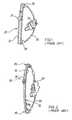
- FIGS. 1 and 2are respectively a front elevation and a perspective view of a typical conventional cable window lift system generally indicated by reference numeral 20 .
- the system 20includes a window regulator rail 22 along which runs a lift plate 24 which in turn is attached to a window glass (not shown).
- a top pulley 26 and a bottom pulley 28are mounted to opposite ends of the rail 22 .
- a cable 30is attached to the lift plate 24 and extends over the top and bottom pulleys, 26 and 28 respectively.
- the cable 30is operably connected to a window regulator motor 32 which causes the cable 30 to move longitudinally and in turn causes the lift plate 24 and any window attached thereto to move along the rail 22 .
- the conventional cable window lift systems 20tend to be vehicle specific. As the window glass moves with the lift plate 24 , and as window glass in automobiles is typically curved, the rail 22 must have a curvature corresponding to the glass and this will vary from vehicle to vehicle and from window to window within a given vehicle. Furthermore the rail must have a length consistent with the window travel which will vary from model to model, for example, a two door model versus a four door model.
- the conventional cable window lift systems 20have an overall height of approximately that of the traveled portion of the rail 22 plus the height of the top pulley 26 and that of the bottom pulley 28 .
- the placement of the top pulley 26 and bottom pulley 28 on the rail 22and typically in a plane parallel to the lift plate travel direction limits the travel of the lift plate 24 to the distance between the pulleys. Any attempt at further travel will result in the lift plate 24 striking either the top or bottom pulley 26 and 28 respectively.
- a cable window regulatorwhich has a first pulley rotatably mounted to a first pulley bracket for rotation about a first pulley axis and a second pulley rotatably mounted to a second pulley bracket for rotation about a second pulley axis.
- a lift plateis securable to a window glass constrained to travel in a window plane. Cables are affixed at opposite and distal ends of the lift plate and trained about the first and second pulleys.
- An drive assemblye.g. motor, crank, etc.
- the first pulley axis and the second pulley axisextending parallel to and spaced from the window plane.
- the first and second pulley bracketsmay be mountable to the structure to position the first and second pulleys out of a path of movement of the window to avoid interference between the lift plate and the pulleys.
- a second cableis affixed to the lift plate at opposite sides thereof and is trained about a second pair of said cable guiding elements to maintain coordinated travel of the lift plate.
- the second cableextends between the second pair of cable guiding elements along a second cable path.
- the first cable pathcrosses the second cable path.
- the at least four cable guiding elementshas an axis of curvature that extends parallel to and is spaced from the closure plane.
- FIG. 1is a front elevation of a prior art cable window lift system
- FIG. 2is a perspective view of the prior art cable window regulator of FIG. 1 ;
- FIG. 3is a schematic illustration of the mounting of one embodiment a cable window regulator according to the present invention.
- FIG. 4is a schematic illustration corresponding to FIG. 3 showing an alternate mounting arrangement
- FIG. 8is a front elevation illustrating a cable window regulator according to the present invention.
- FIG. 10is a front elevation illustrating a cable window regulator according to the present invention having two pairs of first and second pulleys mounted to a door;
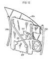
- FIG. 11is a side elevational view illustrating a door module incorporating a window regulator according to the present invention.
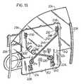
- FIG. 13is side elevational view illustrating a second embodiment of a door module incorporating a window regulator according to the present invention.
- FIG. 14is side elevational view illustrating a third embodiment of a door module incorporating a window regulator according to the present invention.
- a cable window regulator assembly according to the present inventionis generally depicted by reference numeral 40 in FIGS. 3 through 10 .
- the assembly 40has a first pulley 42 rotatably mounted in a first pulley bracket 44 for rotation about a first pulley axis 46 .
- the assembly 40further has a second pulley 52 rotatably mounted in a second pulley bracket 54 for rotation about a second pulley axis 56 .
- a lift plate 60is provided which is securable to a closure panel or window glass 70 and affixed to cables 80 and 81 for movement longitudinally therewith. Cables 80 , 81 are trained about and guided by the first pulley 42 and second pulley 52 , respectively. As shown in FIGS. 5 and 6 , the window regulating cable 80 has end 82 secured to a lower part 62 of the lift plate 60 at tabs 83 and cable 81 has end 84 secured to an upper part 64 of the lift plate 60 at tabs 85 .
- brackets 44 and 54may be mounted to the door 100 away from the upper and lower edges where the door is thinner and space is at a premium.
- a regulator drive assembly 90is operably connected to the cable for causing movement of the cables 80 , 81 to in turn move the lift plate 60 and thereby move the window glass 70 .
- the drive assembly 90can either be a power motor or actuator assembly or a manual crank assembly.
- an outer sheathwill be provided over the cable between the drive assembly 90 and the first and second pulley brackets 42 and 52 respectively to prevent relative movement therebetween.
- FIG. 3illustrates mounting the first pulley bracket 44 and the second pulley bracket 54 directly to the door panel structure 100 . Such a mounting would require that adequate structural integrity be provided by the door panel structure 100 and may be inconvenient during the assembly.
- the remaining Figuresillustrate an intermediate bracket 102 extending between the first pulley bracket 44 and the second pulley bracket 54 to provide further support and accommodate the assembly.
- the intermediate bracket 102may be integrated with the first pulley bracket 44 and the second pulley bracket 54 .
- movement of the lift plate 60is caused by movement of the cables 80 , 81 and guided by the window glass 70 .
- the lift plate 60does not run on a conventional rail.
- Guide rails 110guide and constrain the window glass 70 to travel in a window plane.
- the first pulley 42 and second pulley 52may be offset from the window plane so as not to interfere with the lift plate 60 . Furthermore the first pulley 42 and second pulley 52 are rotatably mounted perpendicular to the window plane unlike the prior art arrangement wherein the top pulley 26 , bottom pulley 24 , rail 22 and lift plate 24 were generally parallel to the window plane.
- the first pulley axis 46 and the second pulley axisare generally parallel to and spaced from each other and the window plane.
- first and second pulleys 42 and 52respectively along with respective first and second pulley brackets 44 and 54 and lift plates 60 .
- An arrangement where two pairs of the foregoing operated by cables 80 , 81 interconnected by an intermediate cable 180 and window regulating motor 90is shown in FIG. 10 .
- the intermediate cable 180assists in maintaining coordinated travel of the glass 70 and prevent the glass 70 from twisting relative to the glass run channels and jamming therein.
- first pulley and the second pulleyscould be replaced by arcuate non-rotating sliding surfaces.
- the arcuate sliding surfacesare commonly utilized in the window regulating industry to replace pulleys.
- the sliding surfacecould be molded directly to the mounting bracket.
- the arcuate sliding surfacewill have a center of curvature along the first and second pulley axi.
- the sliding surfaceis equivalent to a pulley and mount arrangement.
- the carrier panel 202is preferably molded from an organic plastic material.
- the carrier panelhas integrally molded recess 248 for housing cable drum 216 and has a series of grooves 210 and 212 that intersect in a crossing pattern.
- the grooves 210 and 212define cable paths.
- the cable pathscan extend above the surface of the carrier panel 202 .
- Cable guiding elementsnamely pulleys 214 , 218 and 220 , are rotatably mounted at locations of the paths 210 , 212 at turning points where the paths 210 , 212 change direction.
- the cable drum 216is drivingly mounted on the drive assembly 222 mounted on the reverse side of the carrier panel 202 .
- the cable drum 216is located to serves also as a one of the cable guiding elements. At least one of the pulleys is mounted on a movable pivot that is biased to apply a tensioning force to the cable 224 . In the example illustrated, pulley 220 is mounted in such a fashion, and the cable 244 is connected to the lift plate 242 by a tensioning device.
- Carrier panel 202is further provided with mounts 226 , 228 , 230 and 232 , spaced thereabout in a generally rectangular configuration.
- Each of the mounts 226 , 228 , 230 and 232generally comprise a series of flanges that extend perpendicularly to the face of the panel 202 .
- mounts 226 , 228 , 230 and 232are integrally molded onto the surface of the carrier panel 202 .
- Pulleys 234 , 236 , 238 and 240are pivotally mounted on the mounts 226 , 228 , 230 and 232 .
- Pulleys 236 , 238rotate about a first and second upper pulley axi, which are parallel to each other.
- Pulleys 234 , 240rotate about a third and fourth lower pulley axi, which are parallel to each other.
- Upper and lower axiare also parallel to each other. The upper and lower axi also extend generally transverse to the direction of travel of the closure panel 204 .
- Cable 224extends from the drum 216 downwardly along the path 210 , about tensioning pulley 220 , about pulley 240 and upwardly to an upper edge of the right side of lift plate 242 .
- Cable 244extends from the drum 216 upwardly, about pulley 236 and downwardly to the bottom edge of the left side of lift plate 242 .
- Cable 246extends from the lower edge of the right side of lift plate 242 upwardly about pulley 238 downwardly about pulley 218 in groove 212 , about pulley 214 and pulley 234 and upwardly to the upper edge of the left side of lift plate 242 .
- Lift plate 242has been illustrated as a single element extending from pulley 236 to pulley 238 . However, it is apparent to those skilled in the art that lift plate 242 could be two separate elements. Also it is apparent to those skilled in the art, that the arrangement and number of the cable guiding elements, location of the cable drum, location and number of cable tensioning devices can vary without departing from the scope of the present invention.
- FIGS. 13 and 14The examples of such variations are shown in the FIGS. 13 and 14 .
- the cable drum 216 ′is relocated towards the centre of the carrier panel 202 .
- Additional cable guiding pulley 300 ′is located between the cable drum 216 ′ and the pulley 236 .
- the cable guided pulley 300 ′is mounted on a movable pivot that is biased to apply a tensioning force to the cable 244 .
- the cable drum 216 ′′is relocated towards the edge of the carrier panel 202 .
- Additional cable guiding pulley 300 ′′is located between the cable drum 216 ′′ and the pulley 236 .
- the pulley 220is attached directly to the carrier panel 202 .
- the cables 224 and 244are tensioned by the devices positioned in other locations, e.g. in the liftplate 242 .
- Energizing the drive assembly 222 in opposite sensesdrives the window panel 204 between open and closed positions.
- Cable 246operates to maintain the window panel 204 to move squarely relative glass run channels 206 , 208 .
- the carrier panel 202can be configured to support other components that are commonly found in vehicle doors, such as audio speakers latch, switches, wire harness, etc.
Landscapes
- Engineering & Computer Science (AREA)
- Mechanical Engineering (AREA)
- Window Of Vehicle (AREA)
- Power-Operated Mechanisms For Wings (AREA)
Abstract
Description
Claims (7)
Priority Applications (1)
| Application Number | Priority Date | Filing Date | Title |
|---|---|---|---|
| US12/231,452US7905057B2 (en) | 2001-04-26 | 2008-09-03 | Universal cable window regulator assembly for vehicles |
Applications Claiming Priority (4)
| Application Number | Priority Date | Filing Date | Title |
|---|---|---|---|
| US28633001P | 2001-04-26 | 2001-04-26 | |
| US10/476,147US7424788B2 (en) | 2001-04-26 | 2002-04-26 | Universal cable window regulator assembly for vehicles |
| PCT/CA2002/000597WO2002088502A1 (en) | 2001-04-26 | 2002-04-26 | Universal cable window regulator assembly for vehicles |
| US12/231,452US7905057B2 (en) | 2001-04-26 | 2008-09-03 | Universal cable window regulator assembly for vehicles |
Related Parent Applications (3)
| Application Number | Title | Priority Date | Filing Date |
|---|---|---|---|
| US10476147Continuation | 2002-04-26 | ||
| US10/476,147ContinuationUS7424788B2 (en) | 2001-04-26 | 2002-04-26 | Universal cable window regulator assembly for vehicles |
| PCT/CA2002/000597ContinuationWO2002088502A1 (en) | 2001-04-26 | 2002-04-26 | Universal cable window regulator assembly for vehicles |
Publications (2)
| Publication Number | Publication Date |
|---|---|
| US20090000203A1 US20090000203A1 (en) | 2009-01-01 |
| US7905057B2true US7905057B2 (en) | 2011-03-15 |
Family
ID=23098110
Family Applications (2)
| Application Number | Title | Priority Date | Filing Date |
|---|---|---|---|
| US10/476,147Expired - Fee RelatedUS7424788B2 (en) | 2001-04-26 | 2002-04-26 | Universal cable window regulator assembly for vehicles |
| US12/231,452Expired - Fee RelatedUS7905057B2 (en) | 2001-04-26 | 2008-09-03 | Universal cable window regulator assembly for vehicles |
Family Applications Before (1)
| Application Number | Title | Priority Date | Filing Date |
|---|---|---|---|
| US10/476,147Expired - Fee RelatedUS7424788B2 (en) | 2001-04-26 | 2002-04-26 | Universal cable window regulator assembly for vehicles |
Country Status (6)
| Country | Link |
|---|---|
| US (2) | US7424788B2 (en) |
| EP (1) | EP1381746B1 (en) |
| JP (1) | JP2004524469A (en) |
| CA (1) | CA2445436C (en) |
| DE (1) | DE60204768T2 (en) |
| WO (1) | WO2002088502A1 (en) |
Cited By (1)
| Publication number | Priority date | Publication date | Assignee | Title |
|---|---|---|---|---|
| US9771746B2 (en)* | 2015-07-30 | 2017-09-26 | GM Global Technology Operations LLC | Window regulator for a door assembly of a vehicle |
Families Citing this family (21)
| Publication number | Priority date | Publication date | Assignee | Title |
|---|---|---|---|---|
| US7234274B2 (en)* | 2001-07-10 | 2007-06-26 | Kabushikikaisha Ansei | Vehicle door |
| DE10255461B4 (en)* | 2002-11-25 | 2007-05-16 | Faurecia Innenraum Sys Gmbh | Window lift arrangement and motor vehicle door |
| DE102004017645A1 (en)* | 2004-04-02 | 2005-11-03 | Faurecia Innenraum Systeme Gmbh | Window lift assembly and method for mounting a windowpane |
| US7610720B2 (en)* | 2006-04-26 | 2009-11-03 | Magna Closures Inc | Railless window regulator |
| CN101730780B (en) | 2007-05-09 | 2016-06-08 | 马格纳·克劳祖雷斯有限公司 | Window regulator assembly for vehicle |
| US20090051193A1 (en)* | 2007-08-22 | 2009-02-26 | Hernandez Everardo A | Window regulator system for a vehicle door assembly |
| US20090090064A1 (en)* | 2007-10-09 | 2009-04-09 | Tudora Spiridon-Sorin S | Lifter plate with energy absorption members |
| DE102008000477A1 (en)* | 2008-02-29 | 2009-09-17 | Faurecia Innenraum Systeme Gmbh | Door module for a trackless window regulator |
| DE102009002491B4 (en)* | 2009-04-20 | 2017-05-11 | Faurecia Innenraum Systeme Gmbh | Door module for a motor vehicle door with a window regulator |
| WO2010135562A2 (en)* | 2009-05-20 | 2010-11-25 | Inteva Products Llc. | Integrated module carrier plate |
| US9233599B2 (en)* | 2010-07-06 | 2016-01-12 | Brose Fahrzeugteile Gmbh & Co. Kg, Hallstadt | Door module with an aggregate carrier with guide sections formed thereon |
| DE102010031015A1 (en)* | 2010-07-06 | 2012-01-12 | Brose Fahrzeugteile Gmbh & Co. Kg, Hallstadt | Guide rail for a window regulator and door system for a vehicle door |
| FR2964347B1 (en)* | 2010-09-02 | 2012-09-28 | Faurecia Interieur Ind | AUTOMOTIVE VEHICLE DOOR MODULE COMPRISING A WINDOW LIFTING SYSTEM |
| DE102011056233A1 (en)* | 2011-12-09 | 2013-06-13 | Brose Fahrzeugteile Gmbh & Co. Kommanditgesellschaft, Hallstadt | Carrier component for a motor vehicle window regulator with stiffening structure |
| CN103963615B (en)* | 2013-01-29 | 2018-06-01 | 麦格纳覆盖件有限公司 | Car door and the door module for dividing door load-bearing part with multi-section |
| US20180194205A1 (en)* | 2015-07-06 | 2018-07-12 | Grupo Antolín-Ingeniería, S. A. | Window lift operated by structural cables for vehicle doors |
| US9790728B2 (en)* | 2015-07-17 | 2017-10-17 | Hi-Lex Controls, Inc. | Single-rail window regulator assembly |
| US10465430B2 (en)* | 2017-07-20 | 2019-11-05 | Brose Fahrzeugteile Gmbh & Co. Kommanditgesellschaft, Bamberg | Drive device for a vehicle door |
| US11140931B1 (en)* | 2017-09-07 | 2021-10-12 | Jason Stewart | Sweatshirt with cargo carrying accessories |
| CN113661081B (en) | 2019-04-03 | 2024-12-03 | 麦格纳覆盖件有限公司 | For secondary seals on carriers of door modules |
| DE102021132599A1 (en) | 2021-01-08 | 2022-07-14 | Magna Closures Inc. | DOOR MODULE |
Citations (20)
| Publication number | Priority date | Publication date | Assignee | Title |
|---|---|---|---|---|
| DE1630609A1 (en) | 1967-07-12 | 1970-03-26 | Kuester & Co Gmbh Spezialfabri | Window lifter for operating the side windows of motor vehicles |
| US4109417A (en) | 1976-06-21 | 1978-08-29 | Lames Societa Per Azioni | Guide device for a slidable window of a vehicle |
| US4110935A (en) | 1976-11-10 | 1978-09-05 | Sessa T | Cable-actuated, car-side-window-lifting mechanism |
| US4805346A (en) | 1987-09-04 | 1989-02-21 | General Motors Corporation | Vehicle door glass attachment to cable drive window regulator mechanism |
| EP0389873A2 (en) | 1989-03-29 | 1990-10-03 | Aisin Seiki Kabushiki Kaisha | Window regulator apparatus |
| US5174066A (en) | 1989-09-26 | 1992-12-29 | Gencorp Inc. | Door glass cassette for vehicles |
| WO1995001492A1 (en) | 1993-06-30 | 1995-01-12 | Küster & Co. Gmbh | Cable-operated window lifter |
| US5469662A (en) | 1994-11-03 | 1995-11-28 | Chrysler Corporation | Vehicle door construction facilitating window regulator installation and mounting |
| US5477641A (en) | 1992-07-10 | 1995-12-26 | Rockwell Body And Chassis Systems | Safety device for a vehicle electric window lifter with a cable |
| US5694717A (en) | 1994-12-07 | 1997-12-09 | Rockwell Light Vehicle Systems, Inc. | Window winder of the Bowden type for a vehicle door |
| FR2768765A3 (en) | 1997-09-23 | 1999-03-26 | Rockwell Lvs | Window raiser for motor vehicle |
| WO1999059833A1 (en) | 1998-05-15 | 1999-11-25 | Delphi Technologies, Inc. | Module for a vehicle door |
| WO2000035695A1 (en) | 1998-12-03 | 2000-06-22 | Lindblad Hans P | Operating device for displaceable cover elements |
| US6354652B1 (en) | 1997-03-21 | 2002-03-12 | Meritor Light Vehicles System, L.L.C. | Automobile vehicle door module provided with a window raiser without a cable sheath |
| US6397524B1 (en) | 1999-06-16 | 2002-06-04 | Mitsubishi Jidosha Kogyo Kabushiki Kaisha | Door glass raising and falling apparatus |
| US20020083647A1 (en) | 2000-12-28 | 2002-07-04 | Bostian Bruce R. | Structural window lift module |
| US6510657B1 (en) | 1997-04-15 | 2003-01-28 | Meritor Light Vehicle Systems-France | Vehicle door module having two sealed panels |
| EP1314813A1 (en) | 2001-11-23 | 2003-05-28 | N.V. Bekaert S.A. | Cable and window elevator system using such cable |
| US6688043B1 (en) | 1997-05-06 | 2004-02-10 | Brose Fahrzeugteile Gmbh & Co. Kg | Device and method for securing a component to a support part in a vehicle |
| US6820370B2 (en) | 1998-09-22 | 2004-11-23 | Kuster & Co., Gmbh | Motor vehicle window lift with rigidly coupled actuators |
- 2002
- 2002-04-26EPEP02724067Apatent/EP1381746B1/ennot_activeExpired - Lifetime
- 2002-04-26JPJP2002585768Apatent/JP2004524469A/enactivePending
- 2002-04-26WOPCT/CA2002/000597patent/WO2002088502A1/enactiveIP Right Grant
- 2002-04-26DEDE60204768Tpatent/DE60204768T2/ennot_activeExpired - Lifetime
- 2002-04-26USUS10/476,147patent/US7424788B2/ennot_activeExpired - Fee Related
- 2002-04-26CACA002445436Apatent/CA2445436C/ennot_activeExpired - Fee Related
- 2008
- 2008-09-03USUS12/231,452patent/US7905057B2/ennot_activeExpired - Fee Related
Patent Citations (20)
| Publication number | Priority date | Publication date | Assignee | Title |
|---|---|---|---|---|
| DE1630609A1 (en) | 1967-07-12 | 1970-03-26 | Kuester & Co Gmbh Spezialfabri | Window lifter for operating the side windows of motor vehicles |
| US4109417A (en) | 1976-06-21 | 1978-08-29 | Lames Societa Per Azioni | Guide device for a slidable window of a vehicle |
| US4110935A (en) | 1976-11-10 | 1978-09-05 | Sessa T | Cable-actuated, car-side-window-lifting mechanism |
| US4805346A (en) | 1987-09-04 | 1989-02-21 | General Motors Corporation | Vehicle door glass attachment to cable drive window regulator mechanism |
| EP0389873A2 (en) | 1989-03-29 | 1990-10-03 | Aisin Seiki Kabushiki Kaisha | Window regulator apparatus |
| US5174066A (en) | 1989-09-26 | 1992-12-29 | Gencorp Inc. | Door glass cassette for vehicles |
| US5477641A (en) | 1992-07-10 | 1995-12-26 | Rockwell Body And Chassis Systems | Safety device for a vehicle electric window lifter with a cable |
| WO1995001492A1 (en) | 1993-06-30 | 1995-01-12 | Küster & Co. Gmbh | Cable-operated window lifter |
| US5469662A (en) | 1994-11-03 | 1995-11-28 | Chrysler Corporation | Vehicle door construction facilitating window regulator installation and mounting |
| US5694717A (en) | 1994-12-07 | 1997-12-09 | Rockwell Light Vehicle Systems, Inc. | Window winder of the Bowden type for a vehicle door |
| US6354652B1 (en) | 1997-03-21 | 2002-03-12 | Meritor Light Vehicles System, L.L.C. | Automobile vehicle door module provided with a window raiser without a cable sheath |
| US6510657B1 (en) | 1997-04-15 | 2003-01-28 | Meritor Light Vehicle Systems-France | Vehicle door module having two sealed panels |
| US6688043B1 (en) | 1997-05-06 | 2004-02-10 | Brose Fahrzeugteile Gmbh & Co. Kg | Device and method for securing a component to a support part in a vehicle |
| FR2768765A3 (en) | 1997-09-23 | 1999-03-26 | Rockwell Lvs | Window raiser for motor vehicle |
| WO1999059833A1 (en) | 1998-05-15 | 1999-11-25 | Delphi Technologies, Inc. | Module for a vehicle door |
| US6820370B2 (en) | 1998-09-22 | 2004-11-23 | Kuster & Co., Gmbh | Motor vehicle window lift with rigidly coupled actuators |
| WO2000035695A1 (en) | 1998-12-03 | 2000-06-22 | Lindblad Hans P | Operating device for displaceable cover elements |
| US6397524B1 (en) | 1999-06-16 | 2002-06-04 | Mitsubishi Jidosha Kogyo Kabushiki Kaisha | Door glass raising and falling apparatus |
| US20020083647A1 (en) | 2000-12-28 | 2002-07-04 | Bostian Bruce R. | Structural window lift module |
| EP1314813A1 (en) | 2001-11-23 | 2003-05-28 | N.V. Bekaert S.A. | Cable and window elevator system using such cable |
Cited By (1)
| Publication number | Priority date | Publication date | Assignee | Title |
|---|---|---|---|---|
| US9771746B2 (en)* | 2015-07-30 | 2017-09-26 | GM Global Technology Operations LLC | Window regulator for a door assembly of a vehicle |
Also Published As
| Publication number | Publication date |
|---|---|
| US7424788B2 (en) | 2008-09-16 |
| DE60204768T2 (en) | 2006-05-18 |
| CA2445436A1 (en) | 2002-11-07 |
| CA2445436C (en) | 2009-06-09 |
| DE60204768D1 (en) | 2005-07-28 |
| EP1381746A1 (en) | 2004-01-21 |
| US20090000203A1 (en) | 2009-01-01 |
| EP1381746B1 (en) | 2005-06-22 |
| US20040163320A1 (en) | 2004-08-26 |
| WO2002088502A1 (en) | 2002-11-07 |
| JP2004524469A (en) | 2004-08-12 |
Similar Documents
| Publication | Publication Date | Title |
|---|---|---|
| US7905057B2 (en) | Universal cable window regulator assembly for vehicles | |
| US7610720B2 (en) | Railless window regulator | |
| US7104009B2 (en) | Vehicle window carrier plate connected to wires extending through flared openings | |
| US6758013B2 (en) | Integrated roller cable assembly | |
| US6125585A (en) | Sliding window regulator | |
| US6796085B2 (en) | Window regulator | |
| US6112462A (en) | Single-drum dual-cable window regulator | |
| US20070180773A1 (en) | Dual-guided single rail window regulator | |
| JPWO2002075090A1 (en) | Curved glass support structure and window regulator | |
| US20070277443A1 (en) | Motorized sliding window pane | |
| US4660325A (en) | Flexible window regulator assembly | |
| JP2004524469A5 (en) | ||
| US4648206A (en) | Window glass raising and lowering apparatus | |
| EP0174830B1 (en) | A wire compensator for a wire driving window regulator | |
| CZ295178B6 (en) | Articulated overhead gate for particularly small drop heights | |
| US20020092239A1 (en) | Window lift mechanism | |
| US11286705B1 (en) | Cable guide assembly for a window regulator | |
| CN212716351U (en) | Protective door | |
| US6637803B2 (en) | Motor vehicle door drive mechanism, with corresponding door, carriage and vehicle | |
| US20040049986A1 (en) | Automotive side window glass assembly | |
| JP3756424B2 (en) | Wire type window regulator | |
| JP4263788B2 (en) | Power window regulator | |
| JP2570048Y2 (en) | Automotive window wire regulator | |
| JP3850227B2 (en) | Wire type window regulator unit | |
| JPH08199901A (en) | Window regulator |
Legal Events
| Date | Code | Title | Description |
|---|---|---|---|
| AS | Assignment | Owner name:INTIER AUTOMOTIVE CLOSURES INC., CANADA Free format text:ASSIGNMENT OF ASSIGNORS INTEREST;ASSIGNOR:KIREJCZYK, JULIUSZ;REEL/FRAME:023548/0514 Effective date:20020318 Owner name:INTIER AUTOMOTIVE CLOSURES INC.,CANADA Free format text:ASSIGNMENT OF ASSIGNORS INTEREST;ASSIGNOR:KIREJCZYK, JULIUSZ;REEL/FRAME:023548/0431 Effective date:20020318 Owner name:INTIER AUTOMOTIVE CLOSURES INC., CANADA Free format text:ASSIGNMENT OF ASSIGNORS INTEREST;ASSIGNOR:KIREJCZYK, JULIUSZ;REEL/FRAME:023548/0431 Effective date:20020318 | |
| AS | Assignment | Owner name:INTIER AUTOMOTIVE CLOSURES INC.,CANADA Free format text:THIS SUBMISSION CORRECTS AN ERROR IN A COVER SHEET PREVIOUSLY RECORDED. THE PREVIOUSLY RECORDED COVER SHEET LISTS THE INCORRECT APPLICATION NUMBER. THE CORRECT APPLICATION NUMBER IS 12/231452. SEE REEL/FRAME 023548/0431;ASSIGNOR:KIREJCZYK, JULIUSZ;REEL/FRAME:024044/0973 Effective date:20020318 Owner name:INTIER AUTOMOTIVE CLOSURES INC., CANADA Free format text:THIS SUBMISSION CORRECTS AN ERROR IN A COVER SHEET PREVIOUSLY RECORDED. THE PREVIOUSLY RECORDED COVER SHEET LISTS THE INCORRECT APPLICATION NUMBER. THE CORRECT APPLICATION NUMBER IS 12/231452. SEE REEL/FRAME 023548/0431;ASSIGNOR:KIREJCZYK, JULIUSZ;REEL/FRAME:024044/0973 Effective date:20020318 | |
| STCF | Information on status: patent grant | Free format text:PATENTED CASE | |
| FPAY | Fee payment | Year of fee payment:4 | |
| MAFP | Maintenance fee payment | Free format text:PAYMENT OF MAINTENANCE FEE, 8TH YEAR, LARGE ENTITY (ORIGINAL EVENT CODE: M1552); ENTITY STATUS OF PATENT OWNER: LARGE ENTITY Year of fee payment:8 | |
| FEPP | Fee payment procedure | Free format text:MAINTENANCE FEE REMINDER MAILED (ORIGINAL EVENT CODE: REM.); ENTITY STATUS OF PATENT OWNER: LARGE ENTITY | |
| LAPS | Lapse for failure to pay maintenance fees | Free format text:PATENT EXPIRED FOR FAILURE TO PAY MAINTENANCE FEES (ORIGINAL EVENT CODE: EXP.); ENTITY STATUS OF PATENT OWNER: LARGE ENTITY | |
| STCH | Information on status: patent discontinuation | Free format text:PATENT EXPIRED DUE TO NONPAYMENT OF MAINTENANCE FEES UNDER 37 CFR 1.362 | |
| FP | Lapsed due to failure to pay maintenance fee | Effective date:20230315 |