US7903972B2 - Format converter with smart multitap - Google Patents
Format converter with smart multitapDownload PDFInfo
- Publication number
- US7903972B2 US7903972B2US11/456,138US45613806AUS7903972B2US 7903972 B2US7903972 B2US 7903972B2US 45613806 AUS45613806 AUS 45613806AUS 7903972 B2US7903972 B2US 7903972B2
- Authority
- US
- United States
- Prior art keywords
- signal
- service
- level
- format
- output terminals
- Prior art date
- Legal status (The legal status is an assumption and is not a legal conclusion. Google has not performed a legal analysis and makes no representation as to the accuracy of the status listed.)
- Expired - Fee Related, expires
Links
Images
Classifications
- H—ELECTRICITY
- H04—ELECTRIC COMMUNICATION TECHNIQUE
- H04N—PICTORIAL COMMUNICATION, e.g. TELEVISION
- H04N21/00—Selective content distribution, e.g. interactive television or video on demand [VOD]
- H04N21/60—Network structure or processes for video distribution between server and client or between remote clients; Control signalling between clients, server and network components; Transmission of management data between server and client, e.g. sending from server to client commands for recording incoming content stream; Communication details between server and client
- H04N21/61—Network physical structure; Signal processing
- H04N21/6156—Network physical structure; Signal processing specially adapted to the upstream path of the transmission network
- H04N21/6168—Network physical structure; Signal processing specially adapted to the upstream path of the transmission network involving cable transmission, e.g. using a cable modem
- H—ELECTRICITY
- H04—ELECTRIC COMMUNICATION TECHNIQUE
- H04N—PICTORIAL COMMUNICATION, e.g. TELEVISION
- H04N21/00—Selective content distribution, e.g. interactive television or video on demand [VOD]
- H04N21/20—Servers specifically adapted for the distribution of content, e.g. VOD servers; Operations thereof
- H04N21/23—Processing of content or additional data; Elementary server operations; Server middleware
- H04N21/234—Processing of video elementary streams, e.g. splicing of video streams or manipulating encoded video stream scene graphs
- H04N21/2343—Processing of video elementary streams, e.g. splicing of video streams or manipulating encoded video stream scene graphs involving reformatting operations of video signals for distribution or compliance with end-user requests or end-user device requirements
- H04N21/234309—Processing of video elementary streams, e.g. splicing of video streams or manipulating encoded video stream scene graphs involving reformatting operations of video signals for distribution or compliance with end-user requests or end-user device requirements by transcoding between formats or standards, e.g. from MPEG-2 to MPEG-4 or from Quicktime to Realvideo
- H—ELECTRICITY
- H04—ELECTRIC COMMUNICATION TECHNIQUE
- H04N—PICTORIAL COMMUNICATION, e.g. TELEVISION
- H04N21/00—Selective content distribution, e.g. interactive television or video on demand [VOD]
- H04N21/40—Client devices specifically adapted for the reception of or interaction with content, e.g. set-top-box [STB]; Operations thereof
- H—ELECTRICITY
- H04—ELECTRIC COMMUNICATION TECHNIQUE
- H04N—PICTORIAL COMMUNICATION, e.g. TELEVISION
- H04N21/00—Selective content distribution, e.g. interactive television or video on demand [VOD]
- H04N21/60—Network structure or processes for video distribution between server and client or between remote clients; Control signalling between clients, server and network components; Transmission of management data between server and client, e.g. sending from server to client commands for recording incoming content stream; Communication details between server and client
- H04N21/61—Network physical structure; Signal processing
- H04N21/6106—Network physical structure; Signal processing specially adapted to the downstream path of the transmission network
- H04N21/6118—Network physical structure; Signal processing specially adapted to the downstream path of the transmission network involving cable transmission, e.g. using a cable modem
- H—ELECTRICITY
- H04—ELECTRIC COMMUNICATION TECHNIQUE
- H04N—PICTORIAL COMMUNICATION, e.g. TELEVISION
- H04N7/00—Television systems
- H04N7/16—Analogue secrecy systems; Analogue subscription systems
- H04N7/173—Analogue secrecy systems; Analogue subscription systems with two-way working, e.g. subscriber sending a programme selection signal
- H04N7/17309—Transmission or handling of upstream communications
- H—ELECTRICITY
- H04—ELECTRIC COMMUNICATION TECHNIQUE
- H04N—PICTORIAL COMMUNICATION, e.g. TELEVISION
- H04N7/00—Television systems
- H04N7/22—Adaptations for optical transmission
Definitions
- the present disclosureis generally related to data transmission and, more specifically to transmission of data to multiple terminals.
- Electrical signalscan be used for the transmission and distribution of media signals, such as video and audio.
- the signalscould incorporate, for example, analog and/or digital video, Moving Picture Experts Group streams (i.e. MPEG-1, MPEG-2, MPEG-4 (i.e. H.264)), Windows® Media (VC-1) streams, RealAudio streams, or MPEG Audio Layer-3 (mp3) streams, among others that can be used for the transmission of audio and/or video signals in compressed digital streams.
- a signalcould comprise one or more of an audio stream, a video stream, or any other underlying media signals used to convey information (text, graphics, animation, charts, graphs, etc.).
- Such signalsmay be transmitted over a variety of distribution channels such as computer networks, satellite links, cable television (CATV) lines, radio-frequency signals, and digital subscriber lines (DSL), among others.
- a common medium used to transmit the signalsis a fiber optic cable.
- Fiber optic cablesoffer advantages in transmission speed, flexibility of the cables, and bundling of the cables with minimal crosstalk issues, longevity, and upgradeability.
- the fiber optic signalmay be converted to another format or topology, such as, a radio frequency RF) signal.
- RFradio frequency
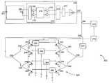
- FIG. 1depicts an exemplary embodiment of a cable television distribution network.
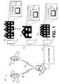
- FIG. 2is a schematic diagram of an exemplary embodiment of a down stream fiber optic to RF converter with a smart multitap used in the cable television distribution network of FIG. 1 .
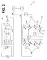
- FIG. 3is a schematic diagram of an exemplary embodiment of the converter and smart tap of FIG. 2 with a burst mode gateway upstream link.
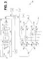
- FIG. 4is a schematic diagram of an exemplary embodiment of the fiber optic to RF converter and smart multitap of FIG. 3 with a broadband digital reverse upstream link.
- FIG. 5is a schematic diagram of an exemplary embodiment of the fiber optic to RF converter and smart multitap of FIG. 2 with digital forward and reverse provided through an optical network terminal.
- FIG. 6is a flow diagram of an exemplary embodiment of a method for downstream transmission using the system provided in FIG. 2 .
- FIG. 7is a flow diagram of an exemplary embodiment of a method for downstream and upstream transmission using the system provided in FIG. 3 .
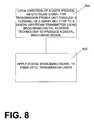
- FIG. 8is a flow diagram of an exemplary embodiment of a method for downstream and upstream transmission using the system provided in FIG. 4 .
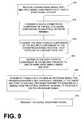
- FIG. 9is a flow diagram of an exemplary embodiment of a method for downstream and upstream transmission using the system provided in FIG. 5 .
- Embodiments of the systemscan be scalable to model different signal topologies, transmission frequencies, bandwidths, and distances.
- An exemplary embodiment of the systemincludes a fiber optic to RF converter and a smart multitap. Although a fiber to RF converter is used in exemplary embodiments throughout the disclosure, conversion between other signal topologies is within the scope of the disclosure.
- the smart multitapincludes a multiple tap for distributing a signal to multiple terminals and a microprocessor to select a particular terminal for a signal. Exemplary embodiments include downstream implementations in which a stream is typically sent from a service provider server to a user. Alternative embodiments include downstream implementations as well as upstream implementations in which a user typically sends a stream to a service provider server.
- FIG. 1depicts an embodiment of one particular electronic system, a cable television distribution network 100 in which embodiments of the converter and smart tap described herein may be used.
- network 100relays multimedia signals received from a number of sources, such as satellites 102 , to a plurality of remote locations 104 .
- multimedia signalscould be, for example, video and/or audio signals, which could also be transmitted with, additional network data, including Internet traffic, teletext, closed captioning, among others.
- the remote location 104could be residences, educational facilities, or businesses that pay for, or otherwise receive cable television programming.
- signals having only one form of mediasuch as audio or video signals alone, are intended to be well within the scope of the disclosure.
- Some exemplary embodiments provided hereinallow multiple sources to have access to a transmission pipe to the home. This enables a user to select from several different types of competing services.
- Such multimedia signals and/or data signalsmay be transmitted over downlink 106 from satellites 102 to respective receiver 108 at cable head end 110 .
- the signals received at cable head end 110may be multiplexed data streams.
- Such data streamsmay comprise compressed multimedia streams transmitted in a variety of formats, such as, but not limited to, MPEG 1, MPEG 2, MPEG 4, VC1, MP3, and/or RealAudio streams.
- Such compressed multimedia streamsmay be transmitted to cable head end 110 at a variety of bit rates.
- the fiber to RF converter and smart multitapmay be located in the communication/transmission system 112 to distribute the stream to multiple units in a high density multiple dwelling unit (MDU), for example. This decreases costs associated with distributing the fiber signal to individual homes.
- MDUhigh density multiple dwelling unit
- the streamscan be transmitted over communication connection 114 to one or more converters at remote location 104 .
- Communication connection 114may be, among others, a communications medium such as fiber optic cable, coaxial cable, telephone line, or wireless connection.
- Decoder 116can, for example, decode and extract multimedia signals from the transmitted streams for playback on playback device 118 .
- Playback device 118could be, for example, a television or audio playback system.
- Decoder 116could be, for example, in a cable television set top box. According to other embodiments, decoder 116 could be associated with a television, stereo system, or computing device (e.g., personal computer, laptop, personal digital assistant (PDA), etc.). Decoder 116 may receive a plurality of programs on a respective channel, each channel carried by a respective multimedia stream (which can include audio and video signals, among others). Although the fiber to RF converter and smart multitap may be described in certain embodiments as being included at the MDU, the converter and smart tap could also be used in a number of other locations, such as in head end 110 or in receiver 108 , among others. For example, according to such an embodiment, receiver 108 may receive a signal in one format that is to be converted into a signal in another format and then transmitted to multiple terminals within head end 110 or outside head end 110 .
- PDApersonal digital assistant
- the methodscan be embodied in any computer readable medium for use by, or in connection with, an instruction execution system, apparatus, or device, such as a computer based system, processor containing system, or other system that can fetch the instructions from the instruction execution system, apparatus, or device to execute the instructions.
- an instruction execution system, apparatus, or devicesuch as a computer based system, processor containing system, or other system that can fetch the instructions from the instruction execution system, apparatus, or device to execute the instructions.
- the underlying methodscan be implemented with any, or a combination of, the following technologies, which are each well-known in the art: (a) discrete logic circuit(s) having logic gates for implementing logic functions upon data signals, an application specific integrated circuit (ASIC) having appropriate combinational logic gates, (a) programmable gate array(s) (PGA), a field programmable gate array (FPGA), etc.; or can be implemented with other technologies now known or later developed.
- ASICapplication specific integrated circuit
- PGAprogrammable gate array
- FPGAfield programmable gate array
- FIG. 2depicts an embodiment of fiber to RF converter and smart multitap system 200 that can be used at a business, educational facility, or MDU, in the cable head end 110 (or decoder 116 , etc.) of FIG. 1 .
- the fiber to RF converter and smart tap system 200comprises fiber to RF converter 202 and smart multitap 228 .
- a fiber to multiple dwelling unit embodimentmay be utilized in a customer premise device for condominiums, apartment complexes, and other high density areas.
- a normal fiber to the home connection with one homemay comprise fiber to RF converter 202 .
- using multiple converters 202is expensive for a multiple dwelling unit due to the increased number of fibers and fiber to RF converters required to feed each individual unit at an MDU location.
- the smart tap shownincludes four terminals, however, any number of taps could be configured. For example, 4 taps, 8 taps, 12 taps, 16 taps, etc.
- Fiber to RF converter 202comprises fiber optic input 201 and RF output 203 .
- Photodiode 206receives a signal from fiber optic input 201 where it is then converted to an RF signal.
- the RF signalis conditioned for output in signal conditioning block 218 , which includes bias stage 208 , pre-amp stage 210 , automatic gain control (AGC) stage 214 , and interstage-amp gain stage 216 .
- the amplifier stagesmay comprise push-pull amplifiers, linear amplifiers, digital amplifiers, or other means of amplification known now or later developed.
- the RF signalis biased by bias network 208 and amplified in pre-amp stage 210 .
- AGCis applied at gain control stage 214 and the signal is again amplified at interstage amp stage 216 .
- Transformer 220then takes the output of push-pull interstage amp 216 to generate the RF signal.
- Tilt stage 222applies a tilt to the signal, and output gain stage 224 applies a final amplification to the signal where it is presented at RF output 203 .
- the total bandwidth of the TV systemis 6 multiplied by 110 channels added to the frequency that the lowest channel is transmitted on plus any offset due to FM radio and over the air channel spacing.
- a coaxial cableWith a coaxial cable, higher frequencies attenuate at a higher rate than lower frequencies. Therefore, a cable-shape loss occurs. Since the cable looks like a low pass filter, as the signal travels down the coaxial cable, a loss occurs proportional to the length of the cable.
- the signalpropagates through tilt stage 222 of converter 202 , it is uptilted such that a higher frequency signal is attenuated less than a lower frequency signal.
- Tilt stage 222counteracts for the cable loss.
- Tilt stage 222may be implemented in one of many circuits known the art. Some gain is sacrificed in tilt stage 222 but the result is a flat signal response.
- Smart multitap 228includes receiver 270 , processor 272 , splitters 230 , 232 , 234 , 236 , 238 , 240 , and 242 , switches 252 , 254 , 256 , 258 , 244 , 246 , 248 , 250 , and terminals 260 , 262 , 264 , and 266 .
- Switch pairs 252 and 244 , 254 and 246 , 256 and 248 , and 258 and 250may each be embodied in a single switch.
- Receiver 270includes a bandpass filter to filter a control signal from RF output 203 . This control signal is tapped off of RF output 203 at coupler 268 .
- the control signalis then sent from receiver 270 to processor 272 to determine which of terminals 260 , 262 , 264 , and 266 should receive the RF signal.
- the RF signalprogresses through splitter 230 , which routes the RF signal into one of two directions. One path goes to splitter 232 while the other path passes through filter 231 and then to splitter 238 .
- Filter 231may be used to filter signals that individual customers have not subscribed to.
- filter 231allows a system operator to remotely enable what services a customer receives.
- the RF signalproceeds through several splitters to create twice the number of feeds as terminals 260 , 262 , 264 and 266 .
- a single RF feed from the non filtered side and a single feed from the filtered side of splitter 230emerge from the final set of splitters.
- Each RF feed, filtered and non-filtered,enters switches 252 , 254 , 256 and 258 .
- Each switch 252 , 254 , 256 , 258receives a command from processor 272 directing it to either use the filtered or non-filtered RF feed.
- the specific RF feed chosen by processor 272emerges from the common port of the switches 252 , 254 , 256 and 258 and exits the multitap through terminals 260 , 262 , 264 and 266 .
- Switches 252 , 254 , 256 and 258also may be terminated via the processor 272 . This is useful for, among other possibilities, disabling a customer who no longer lives in a residence without having to send a technician to turn off the RF feed, or to test for ingress from specific locations that could be degrading system performance.
- the fiber to RF converter and smart multitap applicationuses multiple wavelength optical signals to accomplish transmission of video, voice, and data.
- the receivermay comprise several stages, most of which can be implemented in different ways.
- Photodiode 206can be a stand-alone photodiode if, for example, external wavelength division multiplex components are used. In some embodiments, photodiode 206 may be enclosed in a diplexer or triplexer module which may include other wavelength division optical components.
- Photodiode 206may be biased in a number of ways. In an exemplary embodiments, the biasing may be accomplished through the bias network 208 , which also may serve to improve receiver noise performance. Other options include biasing photodiode 206 directly and using a high impedance preamplifier stage such as preamplifier stage 210 to act as the amplification and matching network for improved noise capability. Preamplifier stage 210 may match photodiode 206 to a lower output impedance. Pre-amp stage 210 and interstage amplifier stage 216 may be co-located into a single integrated circuit, or they may be separate.
- Interstage amp stage 216may, for example, provide sufficient gain for smart multitap 228 to drive a home network comprising a four-way splitter and nominal system coaxial cable loss.
- the final output impedance of terminals 260 , 262 , 264 , and 266may be 75 ohms, which is typical for an in-home distribution network.
- Amplifiers 210 and 216 of signal conditioning block 218may be push-pull circuits, but also could be single-ended stages, if their linearity performance is sufficient. This could eliminate some transformers, thereby reducing costs. If the input noise performance of preamplifier stage 210 is low, cost may be reduced by eliminating the bias network 208 and by biasing photodiode 206 through RF chokes.
- Signal conditioning network 218compensates for a potentially wide input optical power or for variations in the channel loading from head end 110 .
- An open loop compensation stageis incorporated to compensate for a signal derived from a sense line from photodiode 206 .
- the optical input poweris sensed, and a predetermined back-off is set to maintain an acceptable output signal level from terminals 260 , 263 , 264 , and 266 . In this way, installation may be simplified, as there is no need to set the output RF level.
- a 10 db variation in input optical powermay result in a 20 db variation in RF level (prior to the gain control block 218 ), which is excessive for television 118 and set top terminal 116 .
- the predetermined back-off approachis used if an optical modulation index (OMI) is known, and is constant.
- OMIoptical modulation index
- a more sophisticated gain control optionmay include a linear gain control circuit that is driven from an RF detection circuit.
- the detected levelcould be used in a closed loop automatic gain control function, which would be useful if the OMI is not known.
- This gain control circuitregulates the gain based on the power level it receives from the RF detector to maintain a constant level at RF output 203 . Since OMI can change as a function of channel loading, closed loop control is more effective for systems that evolve over time.
- the location of gain control circuit 214is shown between pre-amplifier stage 210 and interstage amplifier stage 216 , but could be placed between interstage amplifier stage 216 and output gain stage 224 .
- Positioning gain control circuit 214 between input stage amplifier 210 and interstage amplifier 216may reduce the linearity requirements of the interstage and post amplifiers 216 and 224 . However, it degrades the noise performance and potentially adds costs due to the need for additional transformers 220 .
- a less expensive automatic gain control approachinvolves limiting the gain variability to 0 db loss or 10 db loss.
- the threshold pointcan be adjusted to optimize noise performance, keeping RF output levels within allowable limits. Adding hysteresis to the control circuitry may eliminate an oscillatory state around the threshold point.
- a feature of fiber optic to RF converter and smart multitap 200is a configurable number of ports offered from one fiber optic line.
- Smart multitapmay provide non-limiting examples of 4, 8, 12, and 16-way capabilities.
- the smart multitapis not limited to any number of port configurations.
- Converter and multitap 200also provide several video conditioning options, full service, tiered, and/or filter services, and the capability to turn off individual ports. The filtered and off state services provide high insulation to prevent video theft.
- Another feature of fiber to RF converter and smart multitap 200is remote enabling capability.
- the service providercan control the services provided through smart multitap 228 . It could provide on (full service), tiered (through the use of the tiering filter capability of the smart multitap section), and off (disable the video) remotely through the network using a signal generated at head end 110 and deciphered by control signal receiver 270 in smart multitap 228 .
- the enabling informationis then sent to processor 272 which enables switches 252 , 254 , 256 , and 258 in smart multitap 228 to select which of terminals 260 , 262 , 264 , and 266 is to receive the RF signal.
- FIG. 3depicts an embodiment of fiber to RF converter and smart multitap system 300 that can be used at a business, educational facility, or MDU, in the cable head end 110 (or decoder 116 , etc.) of FIG. 1 .
- the fiber to RF converter and smart tap system 300comprises fiber to RF converter 302 and smart multitap 328 .
- a fiber to multiple dwelling unit embodimentmay be utilized in a customer premise device for condominiums, apartment complexes, and other high density areas.
- a normal fiber to the home connection with one homemay comprise fiber to RF converter 302 .
- the smart tap shownincludes four terminals, however, any number of taps could be configured. For example, 4 taps, 8 taps, 12 taps, 16 taps, etc.
- Fiber to RF converter 302comprises fiber optic input 301 and RF output 303 .
- Photodiode 306receives a signal from fiber optic input 301 where it is then converted to an RF signal.
- the RF signalis conditioned for output in signal conditioning block 318 , which includes bias stage 308 , pre-amp stage 310 , automatic gain stage (AGC) stage 314 , and interstage-amp gain stage 316 .
- the amplifier stagesmay comprise push-pull amplifiers, linear amplifiers, digital amplifiers, or other means of amplification known now or later developed.
- the RF signalis biased by bias network 308 and amplified in pre-amp stage 310 .
- AGCis applied at gain control stage 314 and the signal is again amplified at interstage amp stage 316 .
- Transformer 320then takes the output of push-pull interstage amp 316 to generate the RF signal.
- Tilt stage 322applies a tilt to the signal, and output gain stage 324 applies a final amplification to the signal where it is presented at RF output 303 .
- each TV channelis transmitted on a different frequency.
- Channel 2may be transmitted at 55.25 MHz, for example, while channel 110 may be transmitted at 745.25 MHz.
- CATVcable television
- the total bandwidth of the TV systemis 6 multiplied by 110 channels added to the frequency that the lowest channel is transmitted on plus any offset due to FM radio and over the air channel spacing.
- a coaxial cableWith a coaxial cable, higher frequencies attenuate at a higher rate than lower frequencies. Therefore, a cable-shape loss occurs. Since the cable looks like a low pass filter, as the signal travels down the coaxial cable, a loss occurs proportional to the length of the cable. When the signal propagates through tilt stage 322 of converter 302 , it is uptilted such that a higher frequency signal is attenuated less than a lower frequency signal.
- Tilt stage 322counteracts for the cable loss.
- Tilt stage 322may be implemented in one of many circuits known the art. Some gain is sacrificed in tilt stage 322 but the result is a flat signal response.
- Smart multitap 328includes receiver 370 , processor 372 , splitters 330 , 332 , 334 , 336 , 338 , 340 , and 342 , switches 352 , 354 , 356 , 358 , 344 , 346 , 348 , 350 , and terminals 360 , 362 , 364 , and 366 .
- Switch pairs 352 and 344 , 354 and 346 , 356 and 348 , and 358 and 350may each be embodied in a single switch.
- Receiver 370includes a bandpass filter to filter a control signal from RF output 303 . This control signal is tapped off of RF output 303 at coupler 368 .
- the control signalis then sent from receiver 370 to processor 372 to determine which of terminals 360 , 362 , 364 , and 366 should receive the RF signal.
- the RF signalprogresses through splitter 330 , which routes the RF signal into one of two directions. One path goes to splitter 332 while the other path passes through filter 331 and then to splitter 338 .
- Filter 331may be used to filter signals that individual customers have not subscribed to.
- filter 331allows a system operator to remotely enable what services a customer receives.
- the RF signalproceeds through several splitters to create twice the number of feeds as terminals 360 , 362 , 364 and 366 .
- a single RF feed from the non filtered side and a single feed from the filtered side of splitter 330emerge from the final set of splitters.
- Each RF feed, filtered and non-filtered,enters switches 352 , 354 , 356 and 358 .
- Each switch 352 , 354 , 356 , 358receives a command from processor 372 directing it to either use the filtered or non-filtered RF feed.
- the specific RF feed chosen by processor 372emerges from the common port of the switches 352 , 354 , 356 and 358 and exits the multitap through terminals 360 , 362 , 364 and 366 .
- Switches 352 , 354 , 356 and 358also may be terminated via the processor 372 . This is useful for, among other possibilities, disabling a customer who no longer lives in a residence without having to send a technician to turn off the RF feed, or to test for ingress from specific locations that could be degrading system performance.
- the fiber to RF converter and smart multitap applicationuses multiple wavelength optical signals to accomplish transmission of video, voice, and data.
- the receivermay comprise several stages, most of which can be implemented in different ways.
- Photodiode 306can be a stand-alone photodiode if, for example, external wavelength division multiplex components are used. In some embodiments, such as that shown in FIG. 3 , the photodiode 306 may be enclosed in a diplexer 304 or triplexer which may include other wavelength division optical components.
- Photodiode 306may be biased in a number of ways. In an exemplary embodiments, the biasing may be accomplished through the bias network 308 , which also may serve to improve receiver noise performance. Other options include biasing photodiode 306 directly and using a high impedance preamplifier stage such as preamplifier stage 310 to act as the amplification and matching network for improved noise capability. Preamplifier stage 310 may match photodiode 306 to a lower output impedance. Pre-amp stage 310 and interstage amplifier stage 316 may be co-located into a single integrated circuit, or they may be separate.
- Interstage amp stage 316may, for example, provide sufficient gain for smart multitap 328 to drive a home network comprising a four-way splitter and nominal system coaxial cable loss.
- the final output impedance of terminals 360 , 362 , 364 , and 366may be 75 ohms, which is typical for an in-home distribution network.
- Amplifiers 310 and 316 of signal conditioning block 318may be push-pull circuits, but also could be single-ended stages, if their linearity performance is sufficient. This could eliminate some transformers, thereby reducing costs. If the input noise performance of preamplifier stage 310 is low, cost may be reduced by eliminating the bias network 308 and by biasing photodiode 306 through RF chokes.
- Signal conditioning network 318compensates for a potentially wide input optical power or for variations in the channel loading from head end 110 .
- An open loop compensation stageis incorporated to compensate for a signal derived from a sense line from photodiode 306 .
- the optical input poweris sensed, and a predetermined back-off is set to maintain an acceptable output signal level from terminals 360 , 363 , 364 , and 366 . In this way, installation may be simplified, as there is no need to set the output RF level.
- a 10 db variation in input optical powermay result in a 20 db variation in RF level (prior to the gain control block 318 ), which is excessive for television 118 and set top terminal 116 .
- the predetermined back-off approachis used if an optical modulation index (OMI) is known, and is constant.
- OMIoptical modulation index
- a more sophisticated gain control optionmay include a linear gain control circuit that is driven from an RF detection circuit.
- the detected levelcould be used in a closed loop automatic gain control function, which would be useful if the OMI is not known.
- This gain control circuitregulates the gain based on the power level it receives from the RF detector to maintain a constant level at RF output 303 . Since OMI can change as a function of channel loading, closed loop control is more effective for systems that evolve over time.
- the location of gain control circuit 314is shown between pre-amplifier stage 310 and interstage amplifier stage 316 , but could be placed between interstage amplifier stage 316 and output gain stage 324 .
- Positioning gain control circuit 314 between input stage amplifier 310 and interstage amplifier 316may reduce the linearity requirements of the interstage and post amplifiers 316 and 324 . However, it degrades the noise performance and potentially adds costs due to the need for additional transformers 320 .
- a less expensive automatic gain control approachinvolves limiting the gain variability to 0 db loss or 10 db loss.
- the threshold pointcan be adjusted to optimize noise performance, keeping RF output levels within allowable limits. Adding hysteresis to the control circuitry may eliminate an oscillatory state around the threshold point.
- a feature of fiber optic to RF converter and smart multitap 300is a configurable number of ports offered from one fiber optic line.
- Smart multitapmay provide non-limiting examples of 4, 8, 12, and 16-way capabilities.
- the smart multitapis not limited to any number of port configurations.
- Converter and multitap 300also provide several video conditioning options, full service, tiered, and/or filter services, and the capability to turn off individual ports. The filtered and off state services provide high insulation to prevent video theft.
- Another feature of fiber to RF converter and smart multitap 300is remote enabling capability.
- the service providercan control the services provided through smart multitap 328 . It could provide on (full service), tiered (through the use of the tiering filter capability of the smart multitap section), and off (disable the video) remotely through the network using a signal generated at head end 110 and deciphered by control signal receiver 370 in smart multitap 328 .
- the enabling informationis then sent to processor 372 which enables switches 352 , 354 , 356 , and 358 in smart multitap 328 to select which of terminals 360 , 362 , 364 , and 366 is to receive the RF signal.
- processor 372being fed signals from an alternate optical wavelength path that feeds an internal or external controller that would send the enabling information either directly to the switches or to processor 372 to control the switches as in the tap configuration of FIG. 3 .
- This communicationuses alternate wavelength signals present on the fiber, which provide a bidirectional digital signal path (used for data and voice communication, as well as control functions).
- external controller switchesmay be provided into the data stream providing full control of processor 372 .
- Diplex filter 374allows the downstream signal from RF output 303 through a high pass filter in diplex filter 374 down to signal splitter 330 .
- the low pass portion of diplex filter 374also allows the upstream signal from the tap network to an upstream signal regulator, shown in FIG. 3 as a burst mode gateway 376 , to be sent by laser 378 onto the fiber optic cable.
- the burst mode gateway 376may disable the upstream transmission when it is not being used. When an upstream transmission is not being used, for example, in the middle of the night when upstream transmissions are infrequent, the burst mode gateway 376 can turn off laser 378 . Therefore, no additional bandwidth is being used by an upstream transmission and noise contributed by laser 378 is reduced from the optical path.
- the fiber to RF converter and smart multitap 300contains a reverse path back to the headend in order to provide interactivity which can be accomplished in many ways.
- a reverse gain blockfeeds a signal up a reverse path through the diplex filter 374 and burst mode gateway 376 to video or digital laser 378 and uses a wavelength other than the one used by the downstream converter as a single return path.
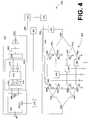
- FIG. 4depicts an embodiment of fiber to RF converter and smart multitap system 400 that can be used at a business, educational facility, or MDU, in the cable head end 110 (or decoder 116 , etc.) of FIG. 1 .
- the fiber to RF converter and smart tap system 400comprises fiber to RF converter 402 and smart multitap 428 .
- a fiber to multiple dwelling unit embodimentmay be utilized in a customer premise device for condominiums, apartment complexes, and other high density areas.
- a normal fiber to the home connection with one homeis just fiber to RF converter 402 .
- using multiple converters 402is expensive for a multiple dwelling unit due to the increased number of fibers and fiber to RF converters required to feed each individual unit at an MDU location.
- the smart tap shownincludes four terminals, however, any number of taps could be configured. For example, 4 taps, 8 taps, 12 taps, 16 taps, etc.
- Fiber to RF converter 402comprises fiber optic input 401 and RF output 403 .
- Photodiode 406receives a signal from fiber optic input 401 where it is then converted to an RF signal.
- the RF signalis conditioned for output in signal conditioning block 418 , which includes bias stage 408 , pre-amp stage 410 , automatic gain control (AGC) stage 414 , and interstage-amp gain stage 416 .
- the amplifier stagesmay comprise push-pull amplifiers, linear amplifiers, digital amplifiers, or other means of amplification known now or later developed.
- the RF signalis biased by bias network 408 and amplified in pre-amp stage 410 .
- AGCis applied at gain control stage 414 and the signal is again amplified at interstage amp stage 416 .
- Transformer 420then takes the output of push-pull interstage amp 416 to generate the RF signal.
- Tilt stage 422applies a tilt to the signal, and output gain stage 424 applies a final amplification to the signal where it is presented at RF output 403 .
- each TV channelis transmitted on a different frequency.
- Channel 2may be transmitted at 55.25 MHz, for example, while channel 110 may be transmitted at 745.25 MHz.
- CATVcable television
- the total bandwidth of the TV systemis 6 multiplied by 110 channels added to the frequency that the lowest channel is transmitted on plus any offset due to FM radio and over the air channel spacing.
- a coaxial cableWith a coaxial cable, higher frequencies attenuate at a higher rate than lower frequencies. Therefore, a cable-shape loss occurs. Since the cable looks like a low pass filter, as the signal travels down the coaxial cable, a loss occurs proportional to the length of the cable. When the signal propagates through tilt stage 422 of converter 402 , it is uptilted such that a higher frequency signal is attenuated less than a lower frequency signal.
- Tilt stage 422counteracts for the cable loss.
- Tilt stage 422may be implemented in one of many circuits known the art. Some gain is sacrificed in tilt stage 422 but the result is a flat signal response.
- Smart multitap 428includes receiver 470 , processor 472 , splitters 430 , 432 , 434 , 436 , 438 , 440 , and 442 , switches 452 , 454 , 456 , 458 , 444 , 446 , 448 , 450 , and terminals 460 , 462 , 464 , and 466 .
- Switch pairs 452 and 444 , 454 and 446 , 456 and 448 , and 458 and 450may each be embodied in a single switch.
- Receiver 470includes a bandpass filter to filter a control signal from RF output 403 . This control signal is tapped off of RF output 403 at coupler 468 .
- the control signalis then sent from receiver 470 to processor 472 to determine which of terminals 460 , 462 , 464 , and 466 should receive the RF signal.
- the RF signalprogresses through splitter 430 , which routes the RF signal into one of two directions. One path goes to splitter 432 while the other path passes through filter 431 and then to splitter 438 .
- Filter 431may be used to filter signals that individual customers have not subscribed to.
- filter 431allows a system operator to remotely enable what services a customer receives.
- the RF signalproceeds through several splitters to create twice the number of feeds as terminals 460 , 462 , 464 and 466 .
- a single RF feed from the non filtered side and a single feed from the filtered side of splitter 430emerge from the final set of splitters.
- Each RF feed, filtered and non-filtered,enters switches 452 , 454 , 456 and 458 .
- Each switch 452 , 454 , 456 , 458receives a command from processor 472 directing it to either use the filtered or non-filtered RF feed.
- the specific RF feed chosen by processor 472emerges from the common port of the switches 452 , 454 , 456 and 458 and exits the multitap through terminals 460 , 462 , 464 and 466 .
- Switches 452 , 454 , 456 and 458also may be terminated via the processor 472 . This is useful for, among other possibilities, disabling a customer who no longer lives in a residence without having to send a technician to turn off the RF feed, or to test for ingress from specific locations that could be degrading system performance.
- the fiber to RF converter and smart multitap applicationuses multiple wavelength optical signals to accomplish transmission of video, voice, and data.
- the receivermay comprise several stages, most of which can be implemented in different ways.
- Photodiode 406can be a stand-alone photodiode if, for example, external wavelength division multiplex components are used. In some embodiments, such as that shown in FIG. 4 , the photodiode 406 may be enclosed in a diplexer 404 or triplexer which may include other wavelength division optical components.
- Photodiode 406may be biased in a number of ways. In an exemplary embodiments, the biasing may be accomplished through bias network 408 , which also may serve to improve receiver noise performance. Other options include biasing photodiode 406 directly and using a high impedance preamplifier stage such as preamplifier stage 410 to act as the amplification and matching network for improved noise capability. Preamplifier stage 410 may match photodiode 406 to a lower output impedance. Pre-amp stage 410 and interstage amplifier stage 416 may be co-located into a single integrated circuit, or they may be separate.
- preamplifier stage 410may match photodiode 406 to a lower output impedance.
- Pre-amp stage 410 and interstage amplifier stage 416may be co-located into a single integrated circuit, or they may be separate.
- Interstage amp stage 416may, for example, provide sufficient gain for smart multitap 428 to drive a home network comprising a four-way splitter and nominal system coaxial cable loss.
- the final output impedance of terminals 460 , 462 , 464 , and 466may be 75 ohms, which is typical for an in-home distribution network.
- Amplifiers 410 and 416 of signal conditioning block 418may be push-pull circuits, but also could be single-ended stages, if their linearity performance is sufficient. This could eliminate some transformers, thereby reducing costs. If the input noise performance of preamplifier stage 410 is low, cost may be reduced by eliminating the bias network 408 and by biasing photodiode 406 through RF chokes.
- Signal conditioning network 418compensates for a potentially wide input optical power or for variations in the channel loading from head end 110 .
- An open loop compensation stageis incorporated to compensate for a signal derived from a sense line from photodiode 406 .
- the optical input poweris sensed, and a predetermined back-off is set to maintain an acceptable output signal level from terminals 460 , 463 , 464 , and 466 . In this way, installation may be simplified, as there is no need to set the output RF level.
- a 10 db variation in input optical powermay result in a 20 db variation in RF level (prior to the gain control block 418 ), which is excessive for television 118 and set top terminal 116 .
- the predetermined back-off approachis used if an optical modulation index (OMI) is known, and is constant.
- OMIoptical modulation index
- a more sophisticated gain control optionmay include a linear gain control circuit that is driven from an RF detection circuit.
- the detected levelcould be used in a closed loop automatic gain control function, which would be useful if the OMI is not known.
- This gain control circuitregulates the gain based on the power level it receives from the RF detector to maintain a constant level at RF output 403 . Since OMI can change as a function of channel loading, closed loop control is more effective for systems that evolve over time.
- the location of gain control circuit 414is shown between pre-amplifier stage 410 and interstage amplifier stage 416 , but could be placed between interstage amplifier stage 416 and output gain stage 424 .
- Positioning gain control circuit 414 between input stage amplifier 410 and interstage amplifier 416may reduce the linearity requirements of the interstage and post amplifiers 416 and 424 . However, it degrades the noise performance and potentially adds costs due to the need for additional transformers 420 .
- a less expensive automatic gain control approachinvolves limiting the gain variability to 0 db loss or 10 db loss.
- the threshold pointcan be adjusted to optimize noise performance, keeping RF output levels within allowable limits. Adding hysteresis to the control circuitry may eliminate an oscillatory state around the threshold point.
- a feature of fiber optic to RF converter and smart multitap 400is a configurable number of ports offered from one fiber optic line.
- Smart multitapmay provide non-limiting examples of 4, 8, 12, and 16-way capabilities.
- the smart multitapis not limited to any number of port configurations.
- Converter and multitap 400also provide several video conditioning options, full service, tiered, and/or filter services, and the capability to turn off individual ports. The filtered and off state services provide high insulation to prevent video theft.
- Another feature of fiber to RF converter and smart multitap 400is remote enabling capability.
- the service providercan control the services provided through smart multitap 428 . It could provide on (full service), tiered (through the use of the tiering filter capability of the smart multitap section), and off (disable the video) remotely through the network using a signal generated at head end 110 and deciphered by control signal receiver 470 in smart multitap 428 .
- the enabling informationis then sent to processor 472 which enables switches 452 , 454 , 456 , and 458 in smart multitap 428 to select which of terminals 460 , 462 , 464 , and 466 is to receive the RF signal.
- processor 472being fed signals from an alternate optical wavelength path that feeds an internal or external controller that would send the enabling information either directly to the switches or to processor 472 to control the switches as in the tap configuration of FIG. 4 .
- This communicationuses alternate wavelength signals present on the fiber, which provide a bidirectional digital signal path (used for data and voice communication, as well as control functions).
- external controller switchesmay be provided into the data stream providing full control of processor 472 .
- Diplex filter 474allows the downstream signal from RF output 403 through a high pass filter in the diplex filter 474 down to the signal splitter 430 .
- the low pass portion of the diplex filter 474also allows the upstream signal from the tap network to an upstream signal regulator, shown in FIG. 4 as a broadband digital reverse (BDR) unit 476 , to be sent by a laser 478 onto the fiber optic cable.
- BDR unit 476digitally integrates the upstream transmission on a separate wavelength.
- the burst mode gateway reversedoes not transmit back upstream unless there is a signal present. For example, at three o'clock in the morning, when no consumer is occupying upstream bandwidth, the data stream is disabled so that if another customer is occupying bandwidth, they get more throughput.
- FIG. 2is an entirely downstream implementation. Commands can be sent downstream and receiver 370 picks off the information from coupler 368 . For the burst mode gateway, cost and reliability are of more concern. The technology is newer and has its own limitations
- the BDR 476is something that most cable companies already use in the head end.
- the burst mode gatewaywould be used better in areas where there is a high concentration of ingress coming from interstates or industrial areas with propagation of noise problems.
- the burst mode gatewayhas a limitation on a number of users. The more uses, the less viable the technology.
- An advantage of the burst mode gatewayincludes turning off its laser when signal is not present. With more users, the likelihood of a use occupying bandwidth increases, reducing the effectiveness of the burst mode gateway.
- the BDR 476digitizes the upstream signal and makes the upstream signal less susceptible to ingress, but it continues to run all the time whereas the burst mode gateway will shut down the laser at certain times under certain conditions. Since the lifetime of the laser is based on its usage, that particular module may last longer in the burst mode gateway embodiment.
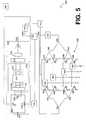
- FIG. 5depicts an embodiment of fiber to RF converter and smart multitap system 500 that can be used at a business, educational facility, or MDU, in the cable head end 110 (or decoder 116 , etc.) of FIG. 1 .
- the fiber to RF converter and smart tap system 500comprises fiber to RF converter 502 and smart multitap 528 .
- a fiber to multiple dwelling unit embodimentmay be utilized in a customer premise device for condominiums, apartment complexes, and other high density areas.
- a normal fiber to the home connection with one homemay comprise fiber to RF converter 502 .
- using multiple converters 502is expensive for a multiple dwelling unit due to the increased number of fibers and fiber to RF converters required to feed each individual unit at an MDU location.
- the smart tap shownincludes four terminals, however, any number of taps could be configured. For example, 4 taps, 8 taps, 12 taps, 16 taps, etc.
- Fiber to RF converter 502comprises fiber optic input 501 and RF output 503 .
- Photodiode 506receives a signal from fiber optic input 501 where it is then converted to an RF signal.
- the RF signalis conditioned for output in signal conditioning block 518 , which includes bias stage 508 , pre-amp stage 510 , automatic gain control (AGC) stage 514 , and interstage-amp gain stage 516 .
- the amplifier stagesmay comprise push-pull amplifiers, linear amplifiers, digital amplifiers, or other means of amplification known now or later developed.
- the RF signalis biased by bias network 508 and amplified in pre-amp stage 510 .
- AGCis applied at gain control stage 514 and the signal is again amplified at interstage amp stage 516 .
- Transformer 520then takes the output of push-pull interstage amp 516 to generate the RF signal.
- Tilt stage 522applies a tilt to the signal, and output gain stage 524 applies a final amplification to the signal where it is presented at RF output 503 .
- the total bandwidth of the TV systemis 6 multiplied by 110 channels added to the frequency that the lowest channel is transmitted on plus any offset due to FM radio and over the air channel spacing.
- a coaxial cableThrough a coaxial cable, higher frequencies attenuate at a higher rate than lower frequencies. Therefore, a cable-shape loss occurs. Since the cable looks like a low pass filter, as the signal travels down the coaxial cable, a loss occurs proportional to the length of the cable. When the signal propagates through tilt stage 522 of converter 502 , it is uptilted such that a higher frequency signal is attenuated less than a lower frequency signal.
- Tilt stage 522counteracts for the cable loss.
- Tilt stage 522may be implemented in one of many circuits known the art. Some gain is sacrificed in tilt stage 522 but the result is a flat signal response.
- Smart multitap 528includes receiver 570 , processor 572 , splitters 530 , 532 , 534 , 536 , 538 , 540 , and 542 , switches 552 , 554 , 556 , 558 , 544 , 546 , 548 , 550 , and terminals 560 , 562 , 564 , and 566 .
- Switch pairs 552 and 544 , 554 and 546 , 556 and 548 , and 558 and 550may each be embodied in a single switch.
- Receiver 570includes a bandpass filter to filter a control signal from RF output 503 . This control signal is tapped off of RF output 503 at coupler 568 .
- the control signalis then sent from receiver 570 to processor 572 to determine which of terminals 560 , 562 , 564 , and 566 should receive the RF signal.
- the RF signalprogresses through splitter 530 , which routes the RF signal into one of two directions. One path goes to splitter 532 while the other path passes through filter 531 and then to splitter 538 .
- Filter 531may be used to filter signals that individual customers have not subscribed to.
- filter 531allows a system operator to remotely enable what services a customer receives.
- the RF signalproceeds through several splitters to create twice the number of feeds as terminals 560 , 562 , 564 and 566 .
- a single RF feed from the non filtered side and a single feed from the filtered side of splitter 530emerge from the final set of splitters.
- Each RF feed, filtered and non-filtered,enters switches 552 , 554 , 556 and 558 .
- Each switch 552 , 554 , 556 , 558receives a command from processor 572 directing it to either use the filtered or non-filtered RF feed.
- the specific RF feed chosen by processor 572emerges from the common port of the switches 552 , 554 , 556 and 558 and exits the multitap through terminals 560 , 562 , 564 and 566 .
- Switches 552 , 554 , 556 and 558also may be terminated via the processor 572 . This is useful for, among other possibilities, disabling a customer who no longer lives in a residence without having to send a technician to turn off the RF feed, or to test for ingress from specific locations that could be degrading system performance.
- the fiber to RF converter and smart multitap applicationuses multiple wavelength optical signals to accomplish transmission of video, voice, and data.
- the receivermay comprise several stages, most of which can be implemented in different ways.
- Photodiode 506can be a stand-alone photodiode if, for example, external wavelength division multiplex components are used. In some embodiments, such as that shown in FIG. 5 , the photodiode 506 may be enclosed in a triplexer 504 which may include other wavelength division optical components.
- Photodiode 506may be biased in a number of ways. In an exemplary embodiments, the biasing may be accomplished through bias network 508 , which also may serve to improve receiver noise performance. Other options include biasing photodiode 506 directly and using a high impedance preamplifier stage such as preamplifier stage 510 to act as the amplification and matching network for improved noise capability. Preamplifier stage 510 may match photodiode 506 to a lower output impedance. Pre-amp stage 510 and interstage amplifier stage 516 may be co-located into a single integrated circuit, or they may be separate.
- Interstage amp stage 516may, for example, provide sufficient gain for smart multitap 528 to drive a home network comprising a four-way splitter and nominal system coaxial cable loss.
- the final output impedance of terminals 560 , 562 , 564 , and 566may be 75 ohms, which is typical for an in-home distribution network.
- Amplifiers 510 and 516 of signal conditioning block 518may be push-pull circuits, but also could be single-ended stages, if their linearity performance is sufficient. This could eliminate some transformers, thereby reducing costs. If the input noise performance of preamplifier stage 510 is low, cost may be reduced by eliminating an bias network 508 and by biasing photodiode 506 through RF chokes.
- Signal conditioning network 518compensates for a potentially wide input optical power or for variations in the channel loading from head end 110 .
- An open loop compensation stageis incorporated to compensate for a signal derived from a sense line from photodiode 506 .
- the optical input poweris sensed, and a predetermined back-off is set to maintain an acceptable output signal level from terminals 560 , 563 , 564 , and 566 . In this way, installation may be simplified, as there is no need to set the output RF level.
- a 10 db variation in input optical powermay result in a 20 db variation in RF level (prior to the gain control block 518 ), which is excessive for television 118 and set top terminal 116 .
- the predetermined back-off approachis used if an optical modulation index (OMI) is known, and is constant.
- OMIoptical modulation index
- a more sophisticated gain control optionmay include a linear gain control circuit that is driven from an RF detection circuit.
- the detected levelcould be used in a closed loop automatic gain control function, which would be useful if the OMI is not known.
- This gain control circuitregulates the gain based on the power level it receives from the RF detector to maintain a constant level at RF output 503 . Since OMI can change as a function of channel loading, closed loop control is more effective for systems that evolve over time.
- the location of gain control circuit 514is shown between pre-amplifier stage 510 and interstage amplifier stage 516 , but could be placed between interstage amplifier stage 516 and output gain stage 524 .
- Positioning gain control circuit 514 between input stage amplifier 510 and interstage amplifier 516may reduce the linearity requirements of the interstage and post amplifiers 516 and 524 . However, it degrades the noise performance and potentially adds costs due to the need for additional transformers 520 .
- a less expensive automatic gain control approachinvolves limiting the gain variability to 0 db loss or 10 db loss.
- the threshold pointcan be adjusted to optimize noise performance, keeping RF output levels within allowable limits. Adding hysteresis to the control circuitry may eliminate an oscillatory state around the threshold point.
- a feature of fiber optic to RF converter and smart multitap 500is a configurable number of ports offered from one fiber optic line.
- Smart multitapmay provide non-limiting examples of 4, 8, 12, and 16-way capabilities.
- the smart multitapis not limited to any number of port configurations.
- Converter and multitap 500also provide several video conditioning options, full service, tiered, and/or filter services, and the capability to turn off individual ports. The filtered and off state services provide high insulation to prevent video theft.
- Another feature of fiber to RF converter and smart multitap 500is remote enabling capability.
- the service providercan control the services provided through smart multitap 528 . It could provide on (full service), tiered (through the use of the tiering filter capability of the smart multitap section), and off (disable the video) remotely through the network using a signal generated at head end 110 and deciphered by control signal receiver 570 in smart multitap 528 .
- the enabling informationis then sent to processor 572 which enables switches 552 , 554 , 556 , and 558 in smart multitap 528 to select which of terminals 560 , 562 , 564 , and 566 is to receive the RF signal.
- the downstream (forward), upstream (reverse), and digital downstream implementationis similar to fiber optic Ethernet capability with video overlay. This could also be called the digital forward and reverse communication length with video overlay.
- This alternative embodimentwould include processor 572 for processing the digital forward signals.
- the signalsare detected on an alternate optical wavelength path.
- the signalswhich may include enabling and/or control information, are provided either directly to the switches or to processor 572 to control the switches.
- This communication linkuses alternate wavelength signals present on the fiber, which provides a bidirectional digital signal path (used for data and voice communication, as well as control functions).
- external controller switchesmay be provided into the data stream providing full control of processor 572 .
- Video overlay with forward and reverse digital capabilityallows for multiple vendors to provide competing services over the same fiber optic cable.
- This system configurationallows multiple vendors to split the initial cost of the system.
- the advantage of this alternative embodimentis that a customer would have a choice of the standard CATV style services and/or digital upstream and digital downstream services that potentially have increased security and bandwidth.
- a usermay have an IP based network bypassing the traditional coaxial network, using a standard Ethernet jack at terminal 590 where a user may router and hub devices for the MDU location for processing and directing the digital information.
- the digital information from the optical network termination (ONT)may be provided to a separate device that handles a conversion to an IP-based or Ethernet-based protocol, as non-limiting examples.
- This configurationis not unlike a digital modem/router with a video overlay.
- the video overlayis provided to the terminals of the smart multitap; however, the optical digital information may or may not.
- triplexer 504there are three wavelengths of light that are different wavelengths. Exemplary wavelengths include downstream video at 1550 nanometers, the upstream/reverse video/digital at 1310 nanometers and the digital forward at 1490 nanometers.
- Diplex filter 574allows the downstream signal from RF output 503 through a high pass filter in the diplex filter 574 down to the signal splitter 530 .
- the low pass portion of the diplex filter 574also allows the upstream signal from the tap network to an upstream signal regulator, shown in FIG. 4 as a digital reverse block 576 that handles the optical network transmission upstream signal.
- the output of the optical network termination terminal 590may also be communicatively coupled to digital reverse block 576 to manage the upstream digital signal.
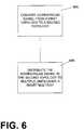
- a signal converterconverts a downstream signal from a first topology to a second topology.
- a fiber optic signalis converted to an RF signal.
- the downstream signal configured according to the second topologyis distributed to multiple units through a smart multitap.
- the particular terminal serviced with the multitapis selected by a processor, which may receive instructions by means of a control signal, as a non-limiting embodiment.
- the control signalmay be modulated on the RF signal and received by a receiver, which demodulates the control signal for use by the processor.
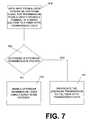
- the flow diagram of FIG. 7provides a method for downstream and upstream transmission according to the system of FIG. 3 .
- an upstream signalis provided for transmission from a unit through a smart multitap to a fiber optic transmission laser.
- decision block 620a determination is made as to whether an upstream transmission is present.
- block 623if an upstream transmission is present, it is propagated to the fiber optic transmission laser.
- block 625if no upstream transmission is present, the upstream transmission laser is disabled by means of a burst mode gateway. By turning off the fiber optic transmission laser, energy is saved, the reliability (proportional to use) of the fiber optic transmission laser is increased, and the bandwidth available for upstream transmission is increased.
- the flow diagram of FIG. 8provides a method for downstream and upstream transmission according to the system of FIG. 4 .
- an upstream signalis provided for transmission from a unit through a smart multitap to a digital upstream transmitter using broadband digital reverse technology to produce a digital broadband upstream signal.
- the digital broadband upstream signalis applied to the fiber optic transmission laser.
- the flow diagram of FIG. 9provides a method for downstream and upstream transmission according to the system of FIG. 5 .
- a downstream signal with multiple signal components in at least a first topologyis received.
- a digital downstream component of the multiple signal componentsis forwarded to an optical network terminal.
- the video overlay component of the multiple components of the downstream signal in the first signal topologyis converted to a second signal topology.
- the resultant video overlay component in the second topologyis distributed to one or more units by means of a smart multitap.
- an upstream signal from a unitis provided for transmission through a terminal of the smart multitap or from the optical network terminal.
- the upstream signalis provided to a digital upstream transmitter.
- the digital broadband signalis transmitted.
- each blockmay represent a module, segment, or portion of code, which comprises one or more executable instructions for implementing the specified logical function(s).
- the functions noted in the blocksmay occur out of the order noted in FIGS. 6-9 .
- two blocks shown in successionmay in fact be executed substantially concurrently or the blocks may sometimes be executed in the reverse order, depending upon the functionality involved, as will be further clarified hereinbelow.
- the software for implementing the converter and smart multitap of FIGS. 2-5which comprises an ordered listing of executable instructions for implementing logical functions, can be embodied in any computer-readable medium for use by or in connection with an instruction execution system, apparatus, or device, such as a computer-based system, processor-containing system, or other system that can fetch the instructions from the instruction execution system, apparatus, or device and execute the instructions.
- a “computer-readable medium”can be any means that can contain, store, communicate, propagate, or transport the program for use by or in connection with the instruction execution system, apparatus, or device.
- the computer readable mediumcan be, for example but not limited to, an electronic, magnetic, optical, electromagnetic, infrared, or semiconductor system, apparatus, device, or propagation medium. More specific examples (a nonexhaustive list) of the computer-readable medium would include the following: an electrical connection (electronic) having one or more wires, a portable computer diskette (magnetic), a random access memory (RAM) (electronic), a read-only memory (ROM) (electronic), an erasable programmable read-only memory (EPROM or Flash memory) (electronic), an optical fiber (optical), and a portable compact disc read-only memory (CDROM) (optical).
- an electrical connectionhaving one or more wires
- a portable computer diskettemagnetic
- RAMrandom access memory
- ROMread-only memory
- EPROM or Flash memoryerasable programmable read-only memory
- CDROMportable compact disc read-only memory
- the computer-readable mediumcould even be paper or another suitable medium upon which the program is printed, as the program can be electronically captured, via for instance optical scanning of the paper or other medium, then compiled, interpreted or otherwise processed in a suitable manner if necessary, and then stored in a computer memory.
- the scope of the present disclosureincludes embodying the functionality of the preferred embodiments of the present disclosure in logic embodied in hardware or software-configured mediums.
- Conditional languagesuch as, among others, “can,” “could,” “might,” or “may,” unless specifically stated otherwise, or otherwise understood within the context as used, is generally intended to convey that certain embodiments could include, while other embodiments do not include, certain features, elements and/or steps. Thus, such conditional language is not generally intended to imply that features, elements and/or steps are in any way required for one or more embodiments or that one or more embodiments necessarily include logic for deciding, with or without user input or prompting, whether these features, elements and/or steps are included or are to be performed in any particular embodiment.
Landscapes
- Engineering & Computer Science (AREA)
- Multimedia (AREA)
- Signal Processing (AREA)
- Two-Way Televisions, Distribution Of Moving Picture Or The Like (AREA)
Abstract
Description
Claims (15)
Priority Applications (2)
| Application Number | Priority Date | Filing Date | Title |
|---|---|---|---|
| US11/456,138US7903972B2 (en) | 2006-07-07 | 2006-07-07 | Format converter with smart multitap |
| PCT/US2007/072700WO2008005958A2 (en) | 2006-07-07 | 2007-07-03 | Communication system for video and bidirectional data transmission between a cable head-end and a plurality of subscribers using a smart multitap |
Applications Claiming Priority (1)
| Application Number | Priority Date | Filing Date | Title |
|---|---|---|---|
| US11/456,138US7903972B2 (en) | 2006-07-07 | 2006-07-07 | Format converter with smart multitap |
Publications (2)
| Publication Number | Publication Date |
|---|---|
| US20080010512A1 US20080010512A1 (en) | 2008-01-10 |
| US7903972B2true US7903972B2 (en) | 2011-03-08 |
Family
ID=38895433
Family Applications (1)
| Application Number | Title | Priority Date | Filing Date |
|---|---|---|---|
| US11/456,138Expired - Fee RelatedUS7903972B2 (en) | 2006-07-07 | 2006-07-07 | Format converter with smart multitap |
Country Status (2)
| Country | Link |
|---|---|
| US (1) | US7903972B2 (en) |
| WO (1) | WO2008005958A2 (en) |
Cited By (162)
| Publication number | Priority date | Publication date | Assignee | Title |
|---|---|---|---|---|
| US9119127B1 (en) | 2012-12-05 | 2015-08-25 | At&T Intellectual Property I, Lp | Backhaul link for distributed antenna system |
| US9154966B2 (en) | 2013-11-06 | 2015-10-06 | At&T Intellectual Property I, Lp | Surface-wave communications and methods thereof |
| US9209902B2 (en) | 2013-12-10 | 2015-12-08 | At&T Intellectual Property I, L.P. | Quasi-optical coupler |
| US9312919B1 (en) | 2014-10-21 | 2016-04-12 | At&T Intellectual Property I, Lp | Transmission device with impairment compensation and methods for use therewith |
| US9461706B1 (en) | 2015-07-31 | 2016-10-04 | At&T Intellectual Property I, Lp | Method and apparatus for exchanging communication signals |
| US9490869B1 (en) | 2015-05-14 | 2016-11-08 | At&T Intellectual Property I, L.P. | Transmission medium having multiple cores and methods for use therewith |
| US9503189B2 (en) | 2014-10-10 | 2016-11-22 | At&T Intellectual Property I, L.P. | Method and apparatus for arranging communication sessions in a communication system |
| US9509415B1 (en) | 2015-06-25 | 2016-11-29 | At&T Intellectual Property I, L.P. | Methods and apparatus for inducing a fundamental wave mode on a transmission medium |
| US9520945B2 (en) | 2014-10-21 | 2016-12-13 | At&T Intellectual Property I, L.P. | Apparatus for providing communication services and methods thereof |
| US9525210B2 (en) | 2014-10-21 | 2016-12-20 | At&T Intellectual Property I, L.P. | Guided-wave transmission device with non-fundamental mode propagation and methods for use therewith |
| US9525524B2 (en) | 2013-05-31 | 2016-12-20 | At&T Intellectual Property I, L.P. | Remote distributed antenna system |
| US9531427B2 (en) | 2014-11-20 | 2016-12-27 | At&T Intellectual Property I, L.P. | Transmission device with mode division multiplexing and methods for use therewith |
| US9564947B2 (en) | 2014-10-21 | 2017-02-07 | At&T Intellectual Property I, L.P. | Guided-wave transmission device with diversity and methods for use therewith |
| US9577307B2 (en) | 2014-10-21 | 2017-02-21 | At&T Intellectual Property I, L.P. | Guided-wave transmission device and methods for use therewith |
| US9608740B2 (en) | 2015-07-15 | 2017-03-28 | At&T Intellectual Property I, L.P. | Method and apparatus for launching a wave mode that mitigates interference |
| US9608692B2 (en) | 2015-06-11 | 2017-03-28 | At&T Intellectual Property I, L.P. | Repeater and methods for use therewith |
| US9615269B2 (en) | 2014-10-02 | 2017-04-04 | At&T Intellectual Property I, L.P. | Method and apparatus that provides fault tolerance in a communication network |
| US9628116B2 (en) | 2015-07-14 | 2017-04-18 | At&T Intellectual Property I, L.P. | Apparatus and methods for transmitting wireless signals |
| US9628854B2 (en) | 2014-09-29 | 2017-04-18 | At&T Intellectual Property I, L.P. | Method and apparatus for distributing content in a communication network |
| US9640850B2 (en) | 2015-06-25 | 2017-05-02 | At&T Intellectual Property I, L.P. | Methods and apparatus for inducing a non-fundamental wave mode on a transmission medium |
| US9653770B2 (en) | 2014-10-21 | 2017-05-16 | At&T Intellectual Property I, L.P. | Guided wave coupler, coupling module and methods for use therewith |
| US9654173B2 (en) | 2014-11-20 | 2017-05-16 | At&T Intellectual Property I, L.P. | Apparatus for powering a communication device and methods thereof |
| US9667317B2 (en) | 2015-06-15 | 2017-05-30 | At&T Intellectual Property I, L.P. | Method and apparatus for providing security using network traffic adjustments |
| US9680670B2 (en) | 2014-11-20 | 2017-06-13 | At&T Intellectual Property I, L.P. | Transmission device with channel equalization and control and methods for use therewith |
| US9685992B2 (en) | 2014-10-03 | 2017-06-20 | At&T Intellectual Property I, L.P. | Circuit panel network and methods thereof |
| US9692101B2 (en) | 2014-08-26 | 2017-06-27 | At&T Intellectual Property I, L.P. | Guided wave couplers for coupling electromagnetic waves between a waveguide surface and a surface of a wire |
| US9705571B2 (en) | 2015-09-16 | 2017-07-11 | At&T Intellectual Property I, L.P. | Method and apparatus for use with a radio distributed antenna system |
| US9705561B2 (en) | 2015-04-24 | 2017-07-11 | At&T Intellectual Property I, L.P. | Directional coupling device and methods for use therewith |
| US9722318B2 (en) | 2015-07-14 | 2017-08-01 | At&T Intellectual Property I, L.P. | Method and apparatus for coupling an antenna to a device |
| US9729197B2 (en) | 2015-10-01 | 2017-08-08 | At&T Intellectual Property I, L.P. | Method and apparatus for communicating network management traffic over a network |
| US9735833B2 (en) | 2015-07-31 | 2017-08-15 | At&T Intellectual Property I, L.P. | Method and apparatus for communications management in a neighborhood network |
| US9742462B2 (en) | 2014-12-04 | 2017-08-22 | At&T Intellectual Property I, L.P. | Transmission medium and communication interfaces and methods for use therewith |
| US9749053B2 (en) | 2015-07-23 | 2017-08-29 | At&T Intellectual Property I, L.P. | Node device, repeater and methods for use therewith |
| US9749013B2 (en) | 2015-03-17 | 2017-08-29 | At&T Intellectual Property I, L.P. | Method and apparatus for reducing attenuation of electromagnetic waves guided by a transmission medium |
| US9748626B2 (en) | 2015-05-14 | 2017-08-29 | At&T Intellectual Property I, L.P. | Plurality of cables having different cross-sectional shapes which are bundled together to form a transmission medium |
| US9755697B2 (en) | 2014-09-15 | 2017-09-05 | At&T Intellectual Property I, L.P. | Method and apparatus for sensing a condition in a transmission medium of electromagnetic waves |
| US9762289B2 (en) | 2014-10-14 | 2017-09-12 | At&T Intellectual Property I, L.P. | Method and apparatus for transmitting or receiving signals in a transportation system |
| US9769128B2 (en) | 2015-09-28 | 2017-09-19 | At&T Intellectual Property I, L.P. | Method and apparatus for encryption of communications over a network |
| US9769020B2 (en) | 2014-10-21 | 2017-09-19 | At&T Intellectual Property I, L.P. | Method and apparatus for responding to events affecting communications in a communication network |
| US9780834B2 (en) | 2014-10-21 | 2017-10-03 | At&T Intellectual Property I, L.P. | Method and apparatus for transmitting electromagnetic waves |
| US9793954B2 (en) | 2015-04-28 | 2017-10-17 | At&T Intellectual Property I, L.P. | Magnetic coupling device and methods for use therewith |
| US9793951B2 (en) | 2015-07-15 | 2017-10-17 | At&T Intellectual Property I, L.P. | Method and apparatus for launching a wave mode that mitigates interference |
| US9793955B2 (en) | 2015-04-24 | 2017-10-17 | At&T Intellectual Property I, Lp | Passive electrical coupling device and methods for use therewith |
| US9800327B2 (en) | 2014-11-20 | 2017-10-24 | At&T Intellectual Property I, L.P. | Apparatus for controlling operations of a communication device and methods thereof |
| US9820146B2 (en) | 2015-06-12 | 2017-11-14 | At&T Intellectual Property I, L.P. | Method and apparatus for authentication and identity management of communicating devices |
| US9838896B1 (en) | 2016-12-09 | 2017-12-05 | At&T Intellectual Property I, L.P. | Method and apparatus for assessing network coverage |
| US9836957B2 (en) | 2015-07-14 | 2017-12-05 | At&T Intellectual Property I, L.P. | Method and apparatus for communicating with premises equipment |
| US9847850B2 (en) | 2014-10-14 | 2017-12-19 | At&T Intellectual Property I, L.P. | Method and apparatus for adjusting a mode of communication in a communication network |
| US9847566B2 (en) | 2015-07-14 | 2017-12-19 | At&T Intellectual Property I, L.P. | Method and apparatus for adjusting a field of a signal to mitigate interference |
| US9853342B2 (en) | 2015-07-14 | 2017-12-26 | At&T Intellectual Property I, L.P. | Dielectric transmission medium connector and methods for use therewith |
| US9860075B1 (en) | 2016-08-26 | 2018-01-02 | At&T Intellectual Property I, L.P. | Method and communication node for broadband distribution |
| US9866309B2 (en) | 2015-06-03 | 2018-01-09 | At&T Intellectual Property I, Lp | Host node device and methods for use therewith |
| US9865911B2 (en) | 2015-06-25 | 2018-01-09 | At&T Intellectual Property I, L.P. | Waveguide system for slot radiating first electromagnetic waves that are combined into a non-fundamental wave mode second electromagnetic wave on a transmission medium |
| US9871282B2 (en) | 2015-05-14 | 2018-01-16 | At&T Intellectual Property I, L.P. | At least one transmission medium having a dielectric surface that is covered at least in part by a second dielectric |
| US9871283B2 (en) | 2015-07-23 | 2018-01-16 | At&T Intellectual Property I, Lp | Transmission medium having a dielectric core comprised of plural members connected by a ball and socket configuration |
| US9876571B2 (en) | 2015-02-20 | 2018-01-23 | At&T Intellectual Property I, Lp | Guided-wave transmission device with non-fundamental mode propagation and methods for use therewith |
| US9876264B2 (en) | 2015-10-02 | 2018-01-23 | At&T Intellectual Property I, Lp | Communication system, guided wave switch and methods for use therewith |
| US9876605B1 (en) | 2016-10-21 | 2018-01-23 | At&T Intellectual Property I, L.P. | Launcher and coupling system to support desired guided wave mode |
| US9882277B2 (en) | 2015-10-02 | 2018-01-30 | At&T Intellectual Property I, Lp | Communication device and antenna assembly with actuated gimbal mount |
| US9882257B2 (en) | 2015-07-14 | 2018-01-30 | At&T Intellectual Property I, L.P. | Method and apparatus for launching a wave mode that mitigates interference |
| US9893795B1 (en) | 2016-12-07 | 2018-02-13 | At&T Intellectual Property I, Lp | Method and repeater for broadband distribution |
| US9906269B2 (en) | 2014-09-17 | 2018-02-27 | At&T Intellectual Property I, L.P. | Monitoring and mitigating conditions in a communication network |
| US9904535B2 (en) | 2015-09-14 | 2018-02-27 | At&T Intellectual Property I, L.P. | Method and apparatus for distributing software |
| US9911020B1 (en) | 2016-12-08 | 2018-03-06 | At&T Intellectual Property I, L.P. | Method and apparatus for tracking via a radio frequency identification device |
| US9912381B2 (en) | 2015-06-03 | 2018-03-06 | At&T Intellectual Property I, Lp | Network termination and methods for use therewith |
| US9912419B1 (en) | 2016-08-24 | 2018-03-06 | At&T Intellectual Property I, L.P. | Method and apparatus for managing a fault in a distributed antenna system |
| US9913139B2 (en) | 2015-06-09 | 2018-03-06 | At&T Intellectual Property I, L.P. | Signal fingerprinting for authentication of communicating devices |
| US9912027B2 (en) | 2015-07-23 | 2018-03-06 | At&T Intellectual Property I, L.P. | Method and apparatus for exchanging communication signals |
| US9917341B2 (en) | 2015-05-27 | 2018-03-13 | At&T Intellectual Property I, L.P. | Apparatus and method for launching electromagnetic waves and for modifying radial dimensions of the propagating electromagnetic waves |
| US9927517B1 (en) | 2016-12-06 | 2018-03-27 | At&T Intellectual Property I, L.P. | Apparatus and methods for sensing rainfall |
| US9948333B2 (en) | 2015-07-23 | 2018-04-17 | At&T Intellectual Property I, L.P. | Method and apparatus for wireless communications to mitigate interference |
| US9948354B2 (en) | 2015-04-28 | 2018-04-17 | At&T Intellectual Property I, L.P. | Magnetic coupling device with reflective plate and methods for use therewith |
| US9954287B2 (en) | 2014-11-20 | 2018-04-24 | At&T Intellectual Property I, L.P. | Apparatus for converting wireless signals and electromagnetic waves and methods thereof |
| US9967173B2 (en) | 2015-07-31 | 2018-05-08 | At&T Intellectual Property I, L.P. | Method and apparatus for authentication and identity management of communicating devices |
| US9973940B1 (en) | 2017-02-27 | 2018-05-15 | At&T Intellectual Property I, L.P. | Apparatus and methods for dynamic impedance matching of a guided wave launcher |
| US9991580B2 (en) | 2016-10-21 | 2018-06-05 | At&T Intellectual Property I, L.P. | Launcher and coupling system for guided wave mode cancellation |
| US9999038B2 (en) | 2013-05-31 | 2018-06-12 | At&T Intellectual Property I, L.P. | Remote distributed antenna system |
| US9997819B2 (en) | 2015-06-09 | 2018-06-12 | At&T Intellectual Property I, L.P. | Transmission medium and method for facilitating propagation of electromagnetic waves via a core |
| US9998870B1 (en) | 2016-12-08 | 2018-06-12 | At&T Intellectual Property I, L.P. | Method and apparatus for proximity sensing |
| US10009901B2 (en) | 2015-09-16 | 2018-06-26 | At&T Intellectual Property I, L.P. | Method, apparatus, and computer-readable storage medium for managing utilization of wireless resources between base stations |
| US10009065B2 (en) | 2012-12-05 | 2018-06-26 | At&T Intellectual Property I, L.P. | Backhaul link for distributed antenna system |
| US10009063B2 (en) | 2015-09-16 | 2018-06-26 | At&T Intellectual Property I, L.P. | Method and apparatus for use with a radio distributed antenna system having an out-of-band reference signal |
| US10009067B2 (en) | 2014-12-04 | 2018-06-26 | At&T Intellectual Property I, L.P. | Method and apparatus for configuring a communication interface |
| US10020587B2 (en) | 2015-07-31 | 2018-07-10 | At&T Intellectual Property I, L.P. | Radial antenna and methods for use therewith |
| US10020844B2 (en) | 2016-12-06 | 2018-07-10 | T&T Intellectual Property I, L.P. | Method and apparatus for broadcast communication via guided waves |
| US10027397B2 (en) | 2016-12-07 | 2018-07-17 | At&T Intellectual Property I, L.P. | Distributed antenna system and methods for use therewith |
| US10033108B2 (en) | 2015-07-14 | 2018-07-24 | At&T Intellectual Property I, L.P. | Apparatus and methods for generating an electromagnetic wave having a wave mode that mitigates interference |
| US10033107B2 (en) | 2015-07-14 | 2018-07-24 | At&T Intellectual Property I, L.P. | Method and apparatus for coupling an antenna to a device |
| US10044409B2 (en) | 2015-07-14 | 2018-08-07 | At&T Intellectual Property I, L.P. | Transmission medium and methods for use therewith |
| US10051629B2 (en) | 2015-09-16 | 2018-08-14 | At&T Intellectual Property I, L.P. | Method and apparatus for use with a radio distributed antenna system having an in-band reference signal |
| US10051483B2 (en) | 2015-10-16 | 2018-08-14 | At&T Intellectual Property I, L.P. | Method and apparatus for directing wireless signals |
| US10069535B2 (en) | 2016-12-08 | 2018-09-04 | At&T Intellectual Property I, L.P. | Apparatus and methods for launching electromagnetic waves having a certain electric field structure |
| US10074890B2 (en) | 2015-10-02 | 2018-09-11 | At&T Intellectual Property I, L.P. | Communication device and antenna with integrated light assembly |
| US10079661B2 (en) | 2015-09-16 | 2018-09-18 | At&T Intellectual Property I, L.P. | Method and apparatus for use with a radio distributed antenna system having a clock reference |
| US10090606B2 (en) | 2015-07-15 | 2018-10-02 | At&T Intellectual Property I, L.P. | Antenna system with dielectric array and methods for use therewith |
| US10090594B2 (en) | 2016-11-23 | 2018-10-02 | At&T Intellectual Property I, L.P. | Antenna system having structural configurations for assembly |
| US10103801B2 (en) | 2015-06-03 | 2018-10-16 | At&T Intellectual Property I, L.P. | Host node device and methods for use therewith |
| US10103422B2 (en) | 2016-12-08 | 2018-10-16 | At&T Intellectual Property I, L.P. | Method and apparatus for mounting network devices |
| US10135145B2 (en) | 2016-12-06 | 2018-11-20 | At&T Intellectual Property I, L.P. | Apparatus and methods for generating an electromagnetic wave along a transmission medium |
| US10135147B2 (en) | 2016-10-18 | 2018-11-20 | At&T Intellectual Property I, L.P. | Apparatus and methods for launching guided waves via an antenna |
| US10135146B2 (en) | 2016-10-18 | 2018-11-20 | At&T Intellectual Property I, L.P. | Apparatus and methods for launching guided waves via circuits |
| US10136434B2 (en) | 2015-09-16 | 2018-11-20 | At&T Intellectual Property I, L.P. | Method and apparatus for use with a radio distributed antenna system having an ultra-wideband control channel |
| US10142086B2 (en) | 2015-06-11 | 2018-11-27 | At&T Intellectual Property I, L.P. | Repeater and methods for use therewith |
| US10139820B2 (en) | 2016-12-07 | 2018-11-27 | At&T Intellectual Property I, L.P. | Method and apparatus for deploying equipment of a communication system |
| US10148016B2 (en) | 2015-07-14 | 2018-12-04 | At&T Intellectual Property I, L.P. | Apparatus and methods for communicating utilizing an antenna array |
| US10144036B2 (en) | 2015-01-30 | 2018-12-04 | At&T Intellectual Property I, L.P. | Method and apparatus for mitigating interference affecting a propagation of electromagnetic waves guided by a transmission medium |
| US10154493B2 (en) | 2015-06-03 | 2018-12-11 | At&T Intellectual Property I, L.P. | Network termination and methods for use therewith |
| US10170840B2 (en) | 2015-07-14 | 2019-01-01 | At&T Intellectual Property I, L.P. | Apparatus and methods for sending or receiving electromagnetic signals |
| US10168695B2 (en) | 2016-12-07 | 2019-01-01 | At&T Intellectual Property I, L.P. | Method and apparatus for controlling an unmanned aircraft |
| US10178445B2 (en) | 2016-11-23 | 2019-01-08 | At&T Intellectual Property I, L.P. | Methods, devices, and systems for load balancing between a plurality of waveguides |
| US10205655B2 (en) | 2015-07-14 | 2019-02-12 | At&T Intellectual Property I, L.P. | Apparatus and methods for communicating utilizing an antenna array and multiple communication paths |
| US10225025B2 (en) | 2016-11-03 | 2019-03-05 | At&T Intellectual Property I, L.P. | Method and apparatus for detecting a fault in a communication system |
| US10224634B2 (en) | 2016-11-03 | 2019-03-05 | At&T Intellectual Property I, L.P. | Methods and apparatus for adjusting an operational characteristic of an antenna |
| US10243270B2 (en) | 2016-12-07 | 2019-03-26 | At&T Intellectual Property I, L.P. | Beam adaptive multi-feed dielectric antenna system and methods for use therewith |
| US10243784B2 (en) | 2014-11-20 | 2019-03-26 | At&T Intellectual Property I, L.P. | System for generating topology information and methods thereof |
| US10264586B2 (en) | 2016-12-09 | 2019-04-16 | At&T Mobility Ii Llc | Cloud-based packet controller and methods for use therewith |
| US10291311B2 (en) | 2016-09-09 | 2019-05-14 | At&T Intellectual Property I, L.P. | Method and apparatus for mitigating a fault in a distributed antenna system |
| US10291334B2 (en) | 2016-11-03 | 2019-05-14 | At&T Intellectual Property I, L.P. | System for detecting a fault in a communication system |
| US10298293B2 (en) | 2017-03-13 | 2019-05-21 | At&T Intellectual Property I, L.P. | Apparatus of communication utilizing wireless network devices |
| US10305190B2 (en) | 2016-12-01 | 2019-05-28 | At&T Intellectual Property I, L.P. | Reflecting dielectric antenna system and methods for use therewith |
| US10312567B2 (en) | 2016-10-26 | 2019-06-04 | At&T Intellectual Property I, L.P. | Launcher with planar strip antenna and methods for use therewith |
| US10320586B2 (en) | 2015-07-14 | 2019-06-11 | At&T Intellectual Property I, L.P. | Apparatus and methods for generating non-interfering electromagnetic waves on an insulated transmission medium |
| US10326494B2 (en) | 2016-12-06 | 2019-06-18 | At&T Intellectual Property I, L.P. | Apparatus for measurement de-embedding and methods for use therewith |
| US10326689B2 (en) | 2016-12-08 | 2019-06-18 | At&T Intellectual Property I, L.P. | Method and system for providing alternative communication paths |
| US10340983B2 (en) | 2016-12-09 | 2019-07-02 | At&T Intellectual Property I, L.P. | Method and apparatus for surveying remote sites via guided wave communications |
| US10340573B2 (en) | 2016-10-26 | 2019-07-02 | At&T Intellectual Property I, L.P. | Launcher with cylindrical coupling device and methods for use therewith |
| US10340601B2 (en) | 2016-11-23 | 2019-07-02 | At&T Intellectual Property I, L.P. | Multi-antenna system and methods for use therewith |
| US10341142B2 (en) | 2015-07-14 | 2019-07-02 | At&T Intellectual Property I, L.P. | Apparatus and methods for generating non-interfering electromagnetic waves on an uninsulated conductor |
| US10340600B2 (en) | 2016-10-18 | 2019-07-02 | At&T Intellectual Property I, L.P. | Apparatus and methods for launching guided waves via plural waveguide systems |
| US10340603B2 (en) | 2016-11-23 | 2019-07-02 | At&T Intellectual Property I, L.P. | Antenna system having shielded structural configurations for assembly |
| US10348391B2 (en) | 2015-06-03 | 2019-07-09 | At&T Intellectual Property I, L.P. | Client node device with frequency conversion and methods for use therewith |
| US10355367B2 (en) | 2015-10-16 | 2019-07-16 | At&T Intellectual Property I, L.P. | Antenna structure for exchanging wireless signals |
| US10359749B2 (en) | 2016-12-07 | 2019-07-23 | At&T Intellectual Property I, L.P. | Method and apparatus for utilities management via guided wave communication |
| US10361489B2 (en) | 2016-12-01 | 2019-07-23 | At&T Intellectual Property I, L.P. | Dielectric dish antenna system and methods for use therewith |
| US10374316B2 (en) | 2016-10-21 | 2019-08-06 | At&T Intellectual Property I, L.P. | System and dielectric antenna with non-uniform dielectric |
| US10382976B2 (en) | 2016-12-06 | 2019-08-13 | At&T Intellectual Property I, L.P. | Method and apparatus for managing wireless communications based on communication paths and network device positions |
| US10389037B2 (en) | 2016-12-08 | 2019-08-20 | At&T Intellectual Property I, L.P. | Apparatus and methods for selecting sections of an antenna array and use therewith |
| US10389029B2 (en) | 2016-12-07 | 2019-08-20 | At&T Intellectual Property I, L.P. | Multi-feed dielectric antenna system with core selection and methods for use therewith |
| US10396887B2 (en) | 2015-06-03 | 2019-08-27 | At&T Intellectual Property I, L.P. | Client node device and methods for use therewith |
| US10411356B2 (en) | 2016-12-08 | 2019-09-10 | At&T Intellectual Property I, L.P. | Apparatus and methods for selectively targeting communication devices with an antenna array |
| US10439675B2 (en) | 2016-12-06 | 2019-10-08 | At&T Intellectual Property I, L.P. | Method and apparatus for repeating guided wave communication signals |
| US10446936B2 (en) | 2016-12-07 | 2019-10-15 | At&T Intellectual Property I, L.P. | Multi-feed dielectric antenna system and methods for use therewith |
| US10498044B2 (en) | 2016-11-03 | 2019-12-03 | At&T Intellectual Property I, L.P. | Apparatus for configuring a surface of an antenna |
| US10530505B2 (en) | 2016-12-08 | 2020-01-07 | At&T Intellectual Property I, L.P. | Apparatus and methods for launching electromagnetic waves along a transmission medium |
| US10535928B2 (en) | 2016-11-23 | 2020-01-14 | At&T Intellectual Property I, L.P. | Antenna system and methods for use therewith |
| US10547348B2 (en) | 2016-12-07 | 2020-01-28 | At&T Intellectual Property I, L.P. | Method and apparatus for switching transmission mediums in a communication system |
| US10601494B2 (en) | 2016-12-08 | 2020-03-24 | At&T Intellectual Property I, L.P. | Dual-band communication device and method for use therewith |
| US10637149B2 (en) | 2016-12-06 | 2020-04-28 | At&T Intellectual Property I, L.P. | Injection molded dielectric antenna and methods for use therewith |
| US10650940B2 (en) | 2015-05-15 | 2020-05-12 | At&T Intellectual Property I, L.P. | Transmission medium having a conductive material and methods for use therewith |
| US10665942B2 (en) | 2015-10-16 | 2020-05-26 | At&T Intellectual Property I, L.P. | Method and apparatus for adjusting wireless communications |
| US10679767B2 (en) | 2015-05-15 | 2020-06-09 | At&T Intellectual Property I, L.P. | Transmission medium having a conductive material and methods for use therewith |
| US10694379B2 (en) | 2016-12-06 | 2020-06-23 | At&T Intellectual Property I, L.P. | Waveguide system with device-based authentication and methods for use therewith |
| US10727599B2 (en) | 2016-12-06 | 2020-07-28 | At&T Intellectual Property I, L.P. | Launcher with slot antenna and methods for use therewith |
| US10755542B2 (en) | 2016-12-06 | 2020-08-25 | At&T Intellectual Property I, L.P. | Method and apparatus for surveillance via guided wave communication |
| US10777873B2 (en) | 2016-12-08 | 2020-09-15 | At&T Intellectual Property I, L.P. | Method and apparatus for mounting network devices |
| US10784670B2 (en) | 2015-07-23 | 2020-09-22 | At&T Intellectual Property I, L.P. | Antenna support for aligning an antenna |
| US10812136B1 (en) | 2019-12-02 | 2020-10-20 | At&T Intellectual Property I, L.P. | Surface wave repeater with controllable isolator and methods for use therewith |
| US10811767B2 (en) | 2016-10-21 | 2020-10-20 | At&T Intellectual Property I, L.P. | System and dielectric antenna with convex dielectric radome |
| US10819035B2 (en) | 2016-12-06 | 2020-10-27 | At&T Intellectual Property I, L.P. | Launcher with helical antenna and methods for use therewith |
| US10916969B2 (en) | 2016-12-08 | 2021-02-09 | At&T Intellectual Property I, L.P. | Method and apparatus for providing power using an inductive coupling |
| US10938108B2 (en) | 2016-12-08 | 2021-03-02 | At&T Intellectual Property I, L.P. | Frequency selective multi-feed dielectric antenna system and methods for use therewith |
| US11032819B2 (en) | 2016-09-15 | 2021-06-08 | At&T Intellectual Property I, L.P. | Method and apparatus for use with a radio distributed antenna system having a control channel reference signal |
Families Citing this family (6)
| Publication number | Priority date | Publication date | Assignee | Title |
|---|---|---|---|---|
| US7788694B2 (en)* | 2005-12-13 | 2010-08-31 | The Directv Group, Inc. | Multiple dwelling unit satellite television delivery system |
| US7783195B2 (en)* | 2006-07-07 | 2010-08-24 | Scientific-Atlanta, Llc | Format converter with smart multitap with digital forward and reverse |
| US7885542B2 (en) | 2006-07-07 | 2011-02-08 | Riggsby Robert R | Format converter with smart multitap and upstream signal regulator |
| US8566896B2 (en)* | 2009-10-23 | 2013-10-22 | Commscope, Inc. Of North Carolina | Addressable network interface units suitable for use in FTTX and RFOG networks and related methods of controlling bandwidth allocation and identifying noise sources in such networks |
| EP4214865A4 (en)* | 2020-09-21 | 2024-06-19 | Teleste Oyj | ARRANGEMENT FOR CONTROLLING ELECTRICITY CONSUMPTION |
| US12095825B2 (en)* | 2021-02-15 | 2024-09-17 | Charter Communications Operating, Llc | System and method for evaluating a customer premise equipment (CPE) device |
Citations (14)
| Publication number | Priority date | Publication date | Assignee | Title |
|---|---|---|---|---|
| EP0651530A2 (en) | 1993-11-03 | 1995-05-03 | AT&T Corp. | Communication systems using passive RF routing |
| WO1997044986A1 (en) | 1996-05-21 | 1997-11-27 | Integrated Network Corporation | Broadband communication system having a virtual circuit space switch |
| US5715020A (en)* | 1993-08-13 | 1998-02-03 | Kabushiki Kaisha Toshiba | Remote control system in which a plurality of remote control units are managed by a single remote control device |
| USH1858H (en) | 1998-06-26 | 2000-09-05 | Scientific-Atlanta, Inc. | Radio frequency sensed, switched reverse path tap |
| WO2001069831A2 (en) | 2000-02-23 | 2001-09-20 | Advent Networks, Inc. | A system and method for distributing information via a communication network |
| WO2003005611A2 (en) | 2001-07-05 | 2003-01-16 | Wave7 Optics, Inc. | System and method for communicating optical signals to multiple subscribers having various bandwidth demands connected to the same optical waveguide |
| WO2003050979A1 (en) | 2001-11-14 | 2003-06-19 | Scientific-Atlanta Inc. | Fiber-to-the-home (ftth) optical receiver having gain control and a remote enable |
| WO2004014010A2 (en) | 2002-08-06 | 2004-02-12 | Scientific-Atlanta, Inc. | A method and device for detecting the presence of a carrier signal transmitted in the reverse rf path |
| US20040111753A1 (en) | 2002-12-05 | 2004-06-10 | Khoi Hoang | Centralized nodes in a fiber optic network |
| US20050144648A1 (en)* | 2003-10-31 | 2005-06-30 | Gotwals Michael D. | Communication network analysis apparatus with internetwork connectivity |
| US20050201752A1 (en)* | 2004-03-12 | 2005-09-15 | Futurewei Technologies, Inc. | System and method for subcarrier modulation as supervisory channel |
| US20060020975A1 (en)* | 2001-07-05 | 2006-01-26 | Wave7 Optics, Inc. | System and method for propagating satellite TV-band, cable TV-band, and data signals over an optical network |
| WO2008005959A2 (en) | 2006-07-07 | 2008-01-10 | Scientific-Atlanta, Inc. | Format converter with smart multitap and upstream signal regulator |
| WO2008011270A2 (en) | 2006-07-07 | 2008-01-24 | Scientific-Atlanta, Inc. | Communication system for video and bidirectional data transmission between a cable head- end and a plurality of subscribers |
- 2006
- 2006-07-07USUS11/456,138patent/US7903972B2/ennot_activeExpired - Fee Related
- 2007
- 2007-07-03WOPCT/US2007/072700patent/WO2008005958A2/enactiveApplication Filing
Patent Citations (15)
| Publication number | Priority date | Publication date | Assignee | Title |
|---|---|---|---|---|
| US5715020A (en)* | 1993-08-13 | 1998-02-03 | Kabushiki Kaisha Toshiba | Remote control system in which a plurality of remote control units are managed by a single remote control device |
| EP0651530A2 (en) | 1993-11-03 | 1995-05-03 | AT&T Corp. | Communication systems using passive RF routing |
| WO1997044986A1 (en) | 1996-05-21 | 1997-11-27 | Integrated Network Corporation | Broadband communication system having a virtual circuit space switch |
| USH1858H (en) | 1998-06-26 | 2000-09-05 | Scientific-Atlanta, Inc. | Radio frequency sensed, switched reverse path tap |
| WO2001069831A2 (en) | 2000-02-23 | 2001-09-20 | Advent Networks, Inc. | A system and method for distributing information via a communication network |
| US20060020975A1 (en)* | 2001-07-05 | 2006-01-26 | Wave7 Optics, Inc. | System and method for propagating satellite TV-band, cable TV-band, and data signals over an optical network |
| WO2003005611A2 (en) | 2001-07-05 | 2003-01-16 | Wave7 Optics, Inc. | System and method for communicating optical signals to multiple subscribers having various bandwidth demands connected to the same optical waveguide |
| US7218855B2 (en)* | 2001-07-05 | 2007-05-15 | Wave7 Optics, Inc. | System and method for communicating optical signals to multiple subscribers having various bandwidth demands connected to the same optical waveguide |
| WO2003050979A1 (en) | 2001-11-14 | 2003-06-19 | Scientific-Atlanta Inc. | Fiber-to-the-home (ftth) optical receiver having gain control and a remote enable |
| WO2004014010A2 (en) | 2002-08-06 | 2004-02-12 | Scientific-Atlanta, Inc. | A method and device for detecting the presence of a carrier signal transmitted in the reverse rf path |
| US20040111753A1 (en) | 2002-12-05 | 2004-06-10 | Khoi Hoang | Centralized nodes in a fiber optic network |
| US20050144648A1 (en)* | 2003-10-31 | 2005-06-30 | Gotwals Michael D. | Communication network analysis apparatus with internetwork connectivity |
| US20050201752A1 (en)* | 2004-03-12 | 2005-09-15 | Futurewei Technologies, Inc. | System and method for subcarrier modulation as supervisory channel |
| WO2008005959A2 (en) | 2006-07-07 | 2008-01-10 | Scientific-Atlanta, Inc. | Format converter with smart multitap and upstream signal regulator |
| WO2008011270A2 (en) | 2006-07-07 | 2008-01-24 | Scientific-Atlanta, Inc. | Communication system for video and bidirectional data transmission between a cable head- end and a plurality of subscribers |
Non-Patent Citations (2)
| Title |
|---|
| U.S. Appl. No. 11/456,145, filed Jul. 7, 2006, Entitled "Format Converter with Smart Multitap and Upstream Signal Regulator." Inventor: Robert R. Riggsby. |
| U.S. Appl. No. 11/456,154, filed Jul. 7, 2006, Entitled "Format Converter with Smart Multitap and Digital Forward and Reverse." Inventor: Robert R. Riggsby. |
Cited By (222)
| Publication number | Priority date | Publication date | Assignee | Title |
|---|---|---|---|---|
| US9788326B2 (en) | 2012-12-05 | 2017-10-10 | At&T Intellectual Property I, L.P. | Backhaul link for distributed antenna system |
| US9119127B1 (en) | 2012-12-05 | 2015-08-25 | At&T Intellectual Property I, Lp | Backhaul link for distributed antenna system |
| US10194437B2 (en) | 2012-12-05 | 2019-01-29 | At&T Intellectual Property I, L.P. | Backhaul link for distributed antenna system |
| US10009065B2 (en) | 2012-12-05 | 2018-06-26 | At&T Intellectual Property I, L.P. | Backhaul link for distributed antenna system |
| US9699785B2 (en) | 2012-12-05 | 2017-07-04 | At&T Intellectual Property I, L.P. | Backhaul link for distributed antenna system |
| US9999038B2 (en) | 2013-05-31 | 2018-06-12 | At&T Intellectual Property I, L.P. | Remote distributed antenna system |
| US9525524B2 (en) | 2013-05-31 | 2016-12-20 | At&T Intellectual Property I, L.P. | Remote distributed antenna system |
| US10091787B2 (en) | 2013-05-31 | 2018-10-02 | At&T Intellectual Property I, L.P. | Remote distributed antenna system |
| US9930668B2 (en) | 2013-05-31 | 2018-03-27 | At&T Intellectual Property I, L.P. | Remote distributed antenna system |
| US10051630B2 (en) | 2013-05-31 | 2018-08-14 | At&T Intellectual Property I, L.P. | Remote distributed antenna system |
| US9467870B2 (en) | 2013-11-06 | 2016-10-11 | At&T Intellectual Property I, L.P. | Surface-wave communications and methods thereof |
| US9661505B2 (en) | 2013-11-06 | 2017-05-23 | At&T Intellectual Property I, L.P. | Surface-wave communications and methods thereof |
| US9154966B2 (en) | 2013-11-06 | 2015-10-06 | At&T Intellectual Property I, Lp | Surface-wave communications and methods thereof |
| US9674711B2 (en) | 2013-11-06 | 2017-06-06 | At&T Intellectual Property I, L.P. | Surface-wave communications and methods thereof |
| US9876584B2 (en) | 2013-12-10 | 2018-01-23 | At&T Intellectual Property I, L.P. | Quasi-optical coupler |
| US9794003B2 (en) | 2013-12-10 | 2017-10-17 | At&T Intellectual Property I, L.P. | Quasi-optical coupler |
| US9209902B2 (en) | 2013-12-10 | 2015-12-08 | At&T Intellectual Property I, L.P. | Quasi-optical coupler |
| US9479266B2 (en) | 2013-12-10 | 2016-10-25 | At&T Intellectual Property I, L.P. | Quasi-optical coupler |
| US10096881B2 (en) | 2014-08-26 | 2018-10-09 | At&T Intellectual Property I, L.P. | Guided wave couplers for coupling electromagnetic waves to an outer surface of a transmission medium |
| US9692101B2 (en) | 2014-08-26 | 2017-06-27 | At&T Intellectual Property I, L.P. | Guided wave couplers for coupling electromagnetic waves between a waveguide surface and a surface of a wire |
| US9768833B2 (en) | 2014-09-15 | 2017-09-19 | At&T Intellectual Property I, L.P. | Method and apparatus for sensing a condition in a transmission medium of electromagnetic waves |
| US9755697B2 (en) | 2014-09-15 | 2017-09-05 | At&T Intellectual Property I, L.P. | Method and apparatus for sensing a condition in a transmission medium of electromagnetic waves |
| US10063280B2 (en) | 2014-09-17 | 2018-08-28 | At&T Intellectual Property I, L.P. | Monitoring and mitigating conditions in a communication network |
| US9906269B2 (en) | 2014-09-17 | 2018-02-27 | At&T Intellectual Property I, L.P. | Monitoring and mitigating conditions in a communication network |
| US9628854B2 (en) | 2014-09-29 | 2017-04-18 | At&T Intellectual Property I, L.P. | Method and apparatus for distributing content in a communication network |
| US9615269B2 (en) | 2014-10-02 | 2017-04-04 | At&T Intellectual Property I, L.P. | Method and apparatus that provides fault tolerance in a communication network |
| US9973416B2 (en) | 2014-10-02 | 2018-05-15 | At&T Intellectual Property I, L.P. | Method and apparatus that provides fault tolerance in a communication network |
| US9998932B2 (en) | 2014-10-02 | 2018-06-12 | At&T Intellectual Property I, L.P. | Method and apparatus that provides fault tolerance in a communication network |
| US9685992B2 (en) | 2014-10-03 | 2017-06-20 | At&T Intellectual Property I, L.P. | Circuit panel network and methods thereof |
| US9866276B2 (en) | 2014-10-10 | 2018-01-09 | At&T Intellectual Property I, L.P. | Method and apparatus for arranging communication sessions in a communication system |
| US9503189B2 (en) | 2014-10-10 | 2016-11-22 | At&T Intellectual Property I, L.P. | Method and apparatus for arranging communication sessions in a communication system |
| US9847850B2 (en) | 2014-10-14 | 2017-12-19 | At&T Intellectual Property I, L.P. | Method and apparatus for adjusting a mode of communication in a communication network |
| US9762289B2 (en) | 2014-10-14 | 2017-09-12 | At&T Intellectual Property I, L.P. | Method and apparatus for transmitting or receiving signals in a transportation system |
| US9973299B2 (en) | 2014-10-14 | 2018-05-15 | At&T Intellectual Property I, L.P. | Method and apparatus for adjusting a mode of communication in a communication network |
| US9577307B2 (en) | 2014-10-21 | 2017-02-21 | At&T Intellectual Property I, L.P. | Guided-wave transmission device and methods for use therewith |
| US9564947B2 (en) | 2014-10-21 | 2017-02-07 | At&T Intellectual Property I, L.P. | Guided-wave transmission device with diversity and methods for use therewith |
| US9596001B2 (en) | 2014-10-21 | 2017-03-14 | At&T Intellectual Property I, L.P. | Apparatus for providing communication services and methods thereof |
| US9960808B2 (en) | 2014-10-21 | 2018-05-01 | At&T Intellectual Property I, L.P. | Guided-wave transmission device and methods for use therewith |
| US9705610B2 (en) | 2014-10-21 | 2017-07-11 | At&T Intellectual Property I, L.P. | Transmission device with impairment compensation and methods for use therewith |
| US9577306B2 (en) | 2014-10-21 | 2017-02-21 | At&T Intellectual Property I, L.P. | Guided-wave transmission device and methods for use therewith |
| US9627768B2 (en) | 2014-10-21 | 2017-04-18 | At&T Intellectual Property I, L.P. | Guided-wave transmission device with non-fundamental mode propagation and methods for use therewith |
| US9571209B2 (en) | 2014-10-21 | 2017-02-14 | At&T Intellectual Property I, L.P. | Transmission device with impairment compensation and methods for use therewith |
| US9948355B2 (en) | 2014-10-21 | 2018-04-17 | At&T Intellectual Property I, L.P. | Apparatus for providing communication services and methods thereof |
| US9876587B2 (en) | 2014-10-21 | 2018-01-23 | At&T Intellectual Property I, L.P. | Transmission device with impairment compensation and methods for use therewith |
| US9912033B2 (en) | 2014-10-21 | 2018-03-06 | At&T Intellectual Property I, Lp | Guided wave coupler, coupling module and methods for use therewith |
| US9525210B2 (en) | 2014-10-21 | 2016-12-20 | At&T Intellectual Property I, L.P. | Guided-wave transmission device with non-fundamental mode propagation and methods for use therewith |
| US9520945B2 (en) | 2014-10-21 | 2016-12-13 | At&T Intellectual Property I, L.P. | Apparatus for providing communication services and methods thereof |
| US9871558B2 (en) | 2014-10-21 | 2018-01-16 | At&T Intellectual Property I, L.P. | Guided-wave transmission device and methods for use therewith |
| US9780834B2 (en) | 2014-10-21 | 2017-10-03 | At&T Intellectual Property I, L.P. | Method and apparatus for transmitting electromagnetic waves |
| US9954286B2 (en) | 2014-10-21 | 2018-04-24 | At&T Intellectual Property I, L.P. | Guided-wave transmission device with non-fundamental mode propagation and methods for use therewith |
| US9653770B2 (en) | 2014-10-21 | 2017-05-16 | At&T Intellectual Property I, L.P. | Guided wave coupler, coupling module and methods for use therewith |
| US9312919B1 (en) | 2014-10-21 | 2016-04-12 | At&T Intellectual Property I, Lp | Transmission device with impairment compensation and methods for use therewith |
| US9769020B2 (en) | 2014-10-21 | 2017-09-19 | At&T Intellectual Property I, L.P. | Method and apparatus for responding to events affecting communications in a communication network |
| US10243784B2 (en) | 2014-11-20 | 2019-03-26 | At&T Intellectual Property I, L.P. | System for generating topology information and methods thereof |
| US9654173B2 (en) | 2014-11-20 | 2017-05-16 | At&T Intellectual Property I, L.P. | Apparatus for powering a communication device and methods thereof |
| US9531427B2 (en) | 2014-11-20 | 2016-12-27 | At&T Intellectual Property I, L.P. | Transmission device with mode division multiplexing and methods for use therewith |
| US9544006B2 (en) | 2014-11-20 | 2017-01-10 | At&T Intellectual Property I, L.P. | Transmission device with mode division multiplexing and methods for use therewith |
| US9749083B2 (en) | 2014-11-20 | 2017-08-29 | At&T Intellectual Property I, L.P. | Transmission device with mode division multiplexing and methods for use therewith |
| US9742521B2 (en) | 2014-11-20 | 2017-08-22 | At&T Intellectual Property I, L.P. | Transmission device with mode division multiplexing and methods for use therewith |
| US9680670B2 (en) | 2014-11-20 | 2017-06-13 | At&T Intellectual Property I, L.P. | Transmission device with channel equalization and control and methods for use therewith |
| US9954287B2 (en) | 2014-11-20 | 2018-04-24 | At&T Intellectual Property I, L.P. | Apparatus for converting wireless signals and electromagnetic waves and methods thereof |
| US9800327B2 (en) | 2014-11-20 | 2017-10-24 | At&T Intellectual Property I, L.P. | Apparatus for controlling operations of a communication device and methods thereof |
| US9712350B2 (en) | 2014-11-20 | 2017-07-18 | At&T Intellectual Property I, L.P. | Transmission device with channel equalization and control and methods for use therewith |
| US9742462B2 (en) | 2014-12-04 | 2017-08-22 | At&T Intellectual Property I, L.P. | Transmission medium and communication interfaces and methods for use therewith |
| US10009067B2 (en) | 2014-12-04 | 2018-06-26 | At&T Intellectual Property I, L.P. | Method and apparatus for configuring a communication interface |
| US10144036B2 (en) | 2015-01-30 | 2018-12-04 | At&T Intellectual Property I, L.P. | Method and apparatus for mitigating interference affecting a propagation of electromagnetic waves guided by a transmission medium |
| US9876570B2 (en) | 2015-02-20 | 2018-01-23 | At&T Intellectual Property I, Lp | Guided-wave transmission device with non-fundamental mode propagation and methods for use therewith |
| US9876571B2 (en) | 2015-02-20 | 2018-01-23 | At&T Intellectual Property I, Lp | Guided-wave transmission device with non-fundamental mode propagation and methods for use therewith |
| US9749013B2 (en) | 2015-03-17 | 2017-08-29 | At&T Intellectual Property I, L.P. | Method and apparatus for reducing attenuation of electromagnetic waves guided by a transmission medium |
| US10224981B2 (en) | 2015-04-24 | 2019-03-05 | At&T Intellectual Property I, Lp | Passive electrical coupling device and methods for use therewith |
| US9793955B2 (en) | 2015-04-24 | 2017-10-17 | At&T Intellectual Property I, Lp | Passive electrical coupling device and methods for use therewith |
| US9705561B2 (en) | 2015-04-24 | 2017-07-11 | At&T Intellectual Property I, L.P. | Directional coupling device and methods for use therewith |
| US9831912B2 (en) | 2015-04-24 | 2017-11-28 | At&T Intellectual Property I, Lp | Directional coupling device and methods for use therewith |
| US9948354B2 (en) | 2015-04-28 | 2018-04-17 | At&T Intellectual Property I, L.P. | Magnetic coupling device with reflective plate and methods for use therewith |
| US9793954B2 (en) | 2015-04-28 | 2017-10-17 | At&T Intellectual Property I, L.P. | Magnetic coupling device and methods for use therewith |
| US9748626B2 (en) | 2015-05-14 | 2017-08-29 | At&T Intellectual Property I, L.P. | Plurality of cables having different cross-sectional shapes which are bundled together to form a transmission medium |
| US9871282B2 (en) | 2015-05-14 | 2018-01-16 | At&T Intellectual Property I, L.P. | At least one transmission medium having a dielectric surface that is covered at least in part by a second dielectric |
| US9490869B1 (en) | 2015-05-14 | 2016-11-08 | At&T Intellectual Property I, L.P. | Transmission medium having multiple cores and methods for use therewith |
| US9887447B2 (en) | 2015-05-14 | 2018-02-06 | At&T Intellectual Property I, L.P. | Transmission medium having multiple cores and methods for use therewith |
| US10650940B2 (en) | 2015-05-15 | 2020-05-12 | At&T Intellectual Property I, L.P. | Transmission medium having a conductive material and methods for use therewith |
| US10679767B2 (en) | 2015-05-15 | 2020-06-09 | At&T Intellectual Property I, L.P. | Transmission medium having a conductive material and methods for use therewith |
| US9917341B2 (en) | 2015-05-27 | 2018-03-13 | At&T Intellectual Property I, L.P. | Apparatus and method for launching electromagnetic waves and for modifying radial dimensions of the propagating electromagnetic waves |
| US9967002B2 (en) | 2015-06-03 | 2018-05-08 | At&T Intellectual I, Lp | Network termination and methods for use therewith |
| US10154493B2 (en) | 2015-06-03 | 2018-12-11 | At&T Intellectual Property I, L.P. | Network termination and methods for use therewith |
| US10812174B2 (en) | 2015-06-03 | 2020-10-20 | At&T Intellectual Property I, L.P. | Client node device and methods for use therewith |
| US10348391B2 (en) | 2015-06-03 | 2019-07-09 | At&T Intellectual Property I, L.P. | Client node device with frequency conversion and methods for use therewith |
| US9935703B2 (en) | 2015-06-03 | 2018-04-03 | At&T Intellectual Property I, L.P. | Host node device and methods for use therewith |
| US10797781B2 (en) | 2015-06-03 | 2020-10-06 | At&T Intellectual Property I, L.P. | Client node device and methods for use therewith |
| US10396887B2 (en) | 2015-06-03 | 2019-08-27 | At&T Intellectual Property I, L.P. | Client node device and methods for use therewith |
| US10103801B2 (en) | 2015-06-03 | 2018-10-16 | At&T Intellectual Property I, L.P. | Host node device and methods for use therewith |
| US10050697B2 (en) | 2015-06-03 | 2018-08-14 | At&T Intellectual Property I, L.P. | Host node device and methods for use therewith |
| US9866309B2 (en) | 2015-06-03 | 2018-01-09 | At&T Intellectual Property I, Lp | Host node device and methods for use therewith |
| US9912381B2 (en) | 2015-06-03 | 2018-03-06 | At&T Intellectual Property I, Lp | Network termination and methods for use therewith |
| US9912382B2 (en) | 2015-06-03 | 2018-03-06 | At&T Intellectual Property I, Lp | Network termination and methods for use therewith |
| US9913139B2 (en) | 2015-06-09 | 2018-03-06 | At&T Intellectual Property I, L.P. | Signal fingerprinting for authentication of communicating devices |
| US9997819B2 (en) | 2015-06-09 | 2018-06-12 | At&T Intellectual Property I, L.P. | Transmission medium and method for facilitating propagation of electromagnetic waves via a core |
| US10027398B2 (en) | 2015-06-11 | 2018-07-17 | At&T Intellectual Property I, Lp | Repeater and methods for use therewith |
| US10142010B2 (en) | 2015-06-11 | 2018-11-27 | At&T Intellectual Property I, L.P. | Repeater and methods for use therewith |
| US10142086B2 (en) | 2015-06-11 | 2018-11-27 | At&T Intellectual Property I, L.P. | Repeater and methods for use therewith |
| US9608692B2 (en) | 2015-06-11 | 2017-03-28 | At&T Intellectual Property I, L.P. | Repeater and methods for use therewith |
| US9820146B2 (en) | 2015-06-12 | 2017-11-14 | At&T Intellectual Property I, L.P. | Method and apparatus for authentication and identity management of communicating devices |
| US9667317B2 (en) | 2015-06-15 | 2017-05-30 | At&T Intellectual Property I, L.P. | Method and apparatus for providing security using network traffic adjustments |
| US9509415B1 (en) | 2015-06-25 | 2016-11-29 | At&T Intellectual Property I, L.P. | Methods and apparatus for inducing a fundamental wave mode on a transmission medium |
| US9640850B2 (en) | 2015-06-25 | 2017-05-02 | At&T Intellectual Property I, L.P. | Methods and apparatus for inducing a non-fundamental wave mode on a transmission medium |
| US9882657B2 (en) | 2015-06-25 | 2018-01-30 | At&T Intellectual Property I, L.P. | Methods and apparatus for inducing a fundamental wave mode on a transmission medium |
| US10069185B2 (en) | 2015-06-25 | 2018-09-04 | At&T Intellectual Property I, L.P. | Methods and apparatus for inducing a non-fundamental wave mode on a transmission medium |
| US9865911B2 (en) | 2015-06-25 | 2018-01-09 | At&T Intellectual Property I, L.P. | Waveguide system for slot radiating first electromagnetic waves that are combined into a non-fundamental wave mode second electromagnetic wave on a transmission medium |
| US9787412B2 (en) | 2015-06-25 | 2017-10-10 | At&T Intellectual Property I, L.P. | Methods and apparatus for inducing a fundamental wave mode on a transmission medium |
| US10090601B2 (en) | 2015-06-25 | 2018-10-02 | At&T Intellectual Property I, L.P. | Waveguide system and methods for inducing a non-fundamental wave mode on a transmission medium |
| US10170840B2 (en) | 2015-07-14 | 2019-01-01 | At&T Intellectual Property I, L.P. | Apparatus and methods for sending or receiving electromagnetic signals |
| US9628116B2 (en) | 2015-07-14 | 2017-04-18 | At&T Intellectual Property I, L.P. | Apparatus and methods for transmitting wireless signals |
| US9882257B2 (en) | 2015-07-14 | 2018-01-30 | At&T Intellectual Property I, L.P. | Method and apparatus for launching a wave mode that mitigates interference |
| US9722318B2 (en) | 2015-07-14 | 2017-08-01 | At&T Intellectual Property I, L.P. | Method and apparatus for coupling an antenna to a device |
| US9836957B2 (en) | 2015-07-14 | 2017-12-05 | At&T Intellectual Property I, L.P. | Method and apparatus for communicating with premises equipment |
| US10148016B2 (en) | 2015-07-14 | 2018-12-04 | At&T Intellectual Property I, L.P. | Apparatus and methods for communicating utilizing an antenna array |
| US10341142B2 (en) | 2015-07-14 | 2019-07-02 | At&T Intellectual Property I, L.P. | Apparatus and methods for generating non-interfering electromagnetic waves on an uninsulated conductor |
| US9847566B2 (en) | 2015-07-14 | 2017-12-19 | At&T Intellectual Property I, L.P. | Method and apparatus for adjusting a field of a signal to mitigate interference |
| US9929755B2 (en) | 2015-07-14 | 2018-03-27 | At&T Intellectual Property I, L.P. | Method and apparatus for coupling an antenna to a device |
| US10320586B2 (en) | 2015-07-14 | 2019-06-11 | At&T Intellectual Property I, L.P. | Apparatus and methods for generating non-interfering electromagnetic waves on an insulated transmission medium |
| US10044409B2 (en) | 2015-07-14 | 2018-08-07 | At&T Intellectual Property I, L.P. | Transmission medium and methods for use therewith |
| US9853342B2 (en) | 2015-07-14 | 2017-12-26 | At&T Intellectual Property I, L.P. | Dielectric transmission medium connector and methods for use therewith |
| US10033107B2 (en) | 2015-07-14 | 2018-07-24 | At&T Intellectual Property I, L.P. | Method and apparatus for coupling an antenna to a device |
| US10205655B2 (en) | 2015-07-14 | 2019-02-12 | At&T Intellectual Property I, L.P. | Apparatus and methods for communicating utilizing an antenna array and multiple communication paths |
| US10033108B2 (en) | 2015-07-14 | 2018-07-24 | At&T Intellectual Property I, L.P. | Apparatus and methods for generating an electromagnetic wave having a wave mode that mitigates interference |
| US9947982B2 (en) | 2015-07-14 | 2018-04-17 | At&T Intellectual Property I, Lp | Dielectric transmission medium connector and methods for use therewith |
| US9608740B2 (en) | 2015-07-15 | 2017-03-28 | At&T Intellectual Property I, L.P. | Method and apparatus for launching a wave mode that mitigates interference |
| US9793951B2 (en) | 2015-07-15 | 2017-10-17 | At&T Intellectual Property I, L.P. | Method and apparatus for launching a wave mode that mitigates interference |
| US10090606B2 (en) | 2015-07-15 | 2018-10-02 | At&T Intellectual Property I, L.P. | Antenna system with dielectric array and methods for use therewith |
| US9912027B2 (en) | 2015-07-23 | 2018-03-06 | At&T Intellectual Property I, L.P. | Method and apparatus for exchanging communication signals |
| US10074886B2 (en) | 2015-07-23 | 2018-09-11 | At&T Intellectual Property I, L.P. | Dielectric transmission medium comprising a plurality of rigid dielectric members coupled together in a ball and socket configuration |
| US9749053B2 (en) | 2015-07-23 | 2017-08-29 | At&T Intellectual Property I, L.P. | Node device, repeater and methods for use therewith |
| US10014946B2 (en) | 2015-07-23 | 2018-07-03 | At&T Intellectual Property I, L.P. | Node device, repeater and methods for use therewith |
| US10432312B2 (en) | 2015-07-23 | 2019-10-01 | At&T Intellectual Property I, L.P. | Node device, repeater and methods for use therewith |
| US10560191B2 (en) | 2015-07-23 | 2020-02-11 | At&T Intellectual Property I, L.P. | Node device, repeater and methods for use therewith |
| US9948333B2 (en) | 2015-07-23 | 2018-04-17 | At&T Intellectual Property I, L.P. | Method and apparatus for wireless communications to mitigate interference |
| US10784670B2 (en) | 2015-07-23 | 2020-09-22 | At&T Intellectual Property I, L.P. | Antenna support for aligning an antenna |
| US9806818B2 (en) | 2015-07-23 | 2017-10-31 | At&T Intellectual Property I, Lp | Node device, repeater and methods for use therewith |
| US9871283B2 (en) | 2015-07-23 | 2018-01-16 | At&T Intellectual Property I, Lp | Transmission medium having a dielectric core comprised of plural members connected by a ball and socket configuration |
| US9838078B2 (en) | 2015-07-31 | 2017-12-05 | At&T Intellectual Property I, L.P. | Method and apparatus for exchanging communication signals |
| US9461706B1 (en) | 2015-07-31 | 2016-10-04 | At&T Intellectual Property I, Lp | Method and apparatus for exchanging communication signals |
| US10020587B2 (en) | 2015-07-31 | 2018-07-10 | At&T Intellectual Property I, L.P. | Radial antenna and methods for use therewith |
| US9735833B2 (en) | 2015-07-31 | 2017-08-15 | At&T Intellectual Property I, L.P. | Method and apparatus for communications management in a neighborhood network |
| US9967173B2 (en) | 2015-07-31 | 2018-05-08 | At&T Intellectual Property I, L.P. | Method and apparatus for authentication and identity management of communicating devices |
| US9904535B2 (en) | 2015-09-14 | 2018-02-27 | At&T Intellectual Property I, L.P. | Method and apparatus for distributing software |
| US10349418B2 (en) | 2015-09-16 | 2019-07-09 | At&T Intellectual Property I, L.P. | Method and apparatus for managing utilization of wireless resources via use of a reference signal to reduce distortion |
| US10051629B2 (en) | 2015-09-16 | 2018-08-14 | At&T Intellectual Property I, L.P. | Method and apparatus for use with a radio distributed antenna system having an in-band reference signal |
| US9705571B2 (en) | 2015-09-16 | 2017-07-11 | At&T Intellectual Property I, L.P. | Method and apparatus for use with a radio distributed antenna system |
| US10079661B2 (en) | 2015-09-16 | 2018-09-18 | At&T Intellectual Property I, L.P. | Method and apparatus for use with a radio distributed antenna system having a clock reference |
| US10225842B2 (en) | 2015-09-16 | 2019-03-05 | At&T Intellectual Property I, L.P. | Method, device and storage medium for communications using a modulated signal and a reference signal |
| US10009901B2 (en) | 2015-09-16 | 2018-06-26 | At&T Intellectual Property I, L.P. | Method, apparatus, and computer-readable storage medium for managing utilization of wireless resources between base stations |
| US10009063B2 (en) | 2015-09-16 | 2018-06-26 | At&T Intellectual Property I, L.P. | Method and apparatus for use with a radio distributed antenna system having an out-of-band reference signal |
| US10136434B2 (en) | 2015-09-16 | 2018-11-20 | At&T Intellectual Property I, L.P. | Method and apparatus for use with a radio distributed antenna system having an ultra-wideband control channel |
| US9769128B2 (en) | 2015-09-28 | 2017-09-19 | At&T Intellectual Property I, L.P. | Method and apparatus for encryption of communications over a network |
| US9729197B2 (en) | 2015-10-01 | 2017-08-08 | At&T Intellectual Property I, L.P. | Method and apparatus for communicating network management traffic over a network |
| US9882277B2 (en) | 2015-10-02 | 2018-01-30 | At&T Intellectual Property I, Lp | Communication device and antenna assembly with actuated gimbal mount |
| US9876264B2 (en) | 2015-10-02 | 2018-01-23 | At&T Intellectual Property I, Lp | Communication system, guided wave switch and methods for use therewith |
| US10074890B2 (en) | 2015-10-02 | 2018-09-11 | At&T Intellectual Property I, L.P. | Communication device and antenna with integrated light assembly |
| US10665942B2 (en) | 2015-10-16 | 2020-05-26 | At&T Intellectual Property I, L.P. | Method and apparatus for adjusting wireless communications |
| US10051483B2 (en) | 2015-10-16 | 2018-08-14 | At&T Intellectual Property I, L.P. | Method and apparatus for directing wireless signals |
| US10355367B2 (en) | 2015-10-16 | 2019-07-16 | At&T Intellectual Property I, L.P. | Antenna structure for exchanging wireless signals |
| US9912419B1 (en) | 2016-08-24 | 2018-03-06 | At&T Intellectual Property I, L.P. | Method and apparatus for managing a fault in a distributed antenna system |
| US9860075B1 (en) | 2016-08-26 | 2018-01-02 | At&T Intellectual Property I, L.P. | Method and communication node for broadband distribution |
| US10291311B2 (en) | 2016-09-09 | 2019-05-14 | At&T Intellectual Property I, L.P. | Method and apparatus for mitigating a fault in a distributed antenna system |
| US11032819B2 (en) | 2016-09-15 | 2021-06-08 | At&T Intellectual Property I, L.P. | Method and apparatus for use with a radio distributed antenna system having a control channel reference signal |
| US10340600B2 (en) | 2016-10-18 | 2019-07-02 | At&T Intellectual Property I, L.P. | Apparatus and methods for launching guided waves via plural waveguide systems |
| US10135146B2 (en) | 2016-10-18 | 2018-11-20 | At&T Intellectual Property I, L.P. | Apparatus and methods for launching guided waves via circuits |
| US10135147B2 (en) | 2016-10-18 | 2018-11-20 | At&T Intellectual Property I, L.P. | Apparatus and methods for launching guided waves via an antenna |
| US9991580B2 (en) | 2016-10-21 | 2018-06-05 | At&T Intellectual Property I, L.P. | Launcher and coupling system for guided wave mode cancellation |
| US10811767B2 (en) | 2016-10-21 | 2020-10-20 | At&T Intellectual Property I, L.P. | System and dielectric antenna with convex dielectric radome |
| US10374316B2 (en) | 2016-10-21 | 2019-08-06 | At&T Intellectual Property I, L.P. | System and dielectric antenna with non-uniform dielectric |
| US9876605B1 (en) | 2016-10-21 | 2018-01-23 | At&T Intellectual Property I, L.P. | Launcher and coupling system to support desired guided wave mode |
| US10340573B2 (en) | 2016-10-26 | 2019-07-02 | At&T Intellectual Property I, L.P. | Launcher with cylindrical coupling device and methods for use therewith |
| US10312567B2 (en) | 2016-10-26 | 2019-06-04 | At&T Intellectual Property I, L.P. | Launcher with planar strip antenna and methods for use therewith |
| US10291334B2 (en) | 2016-11-03 | 2019-05-14 | At&T Intellectual Property I, L.P. | System for detecting a fault in a communication system |
| US10225025B2 (en) | 2016-11-03 | 2019-03-05 | At&T Intellectual Property I, L.P. | Method and apparatus for detecting a fault in a communication system |
| US10498044B2 (en) | 2016-11-03 | 2019-12-03 | At&T Intellectual Property I, L.P. | Apparatus for configuring a surface of an antenna |
| US10224634B2 (en) | 2016-11-03 | 2019-03-05 | At&T Intellectual Property I, L.P. | Methods and apparatus for adjusting an operational characteristic of an antenna |
| US10178445B2 (en) | 2016-11-23 | 2019-01-08 | At&T Intellectual Property I, L.P. | Methods, devices, and systems for load balancing between a plurality of waveguides |
| US10340603B2 (en) | 2016-11-23 | 2019-07-02 | At&T Intellectual Property I, L.P. | Antenna system having shielded structural configurations for assembly |
| US10535928B2 (en) | 2016-11-23 | 2020-01-14 | At&T Intellectual Property I, L.P. | Antenna system and methods for use therewith |
| US10340601B2 (en) | 2016-11-23 | 2019-07-02 | At&T Intellectual Property I, L.P. | Multi-antenna system and methods for use therewith |
| US10090594B2 (en) | 2016-11-23 | 2018-10-02 | At&T Intellectual Property I, L.P. | Antenna system having structural configurations for assembly |
| US10305190B2 (en) | 2016-12-01 | 2019-05-28 | At&T Intellectual Property I, L.P. | Reflecting dielectric antenna system and methods for use therewith |
| US10361489B2 (en) | 2016-12-01 | 2019-07-23 | At&T Intellectual Property I, L.P. | Dielectric dish antenna system and methods for use therewith |
| US10819035B2 (en) | 2016-12-06 | 2020-10-27 | At&T Intellectual Property I, L.P. | Launcher with helical antenna and methods for use therewith |
| US10694379B2 (en) | 2016-12-06 | 2020-06-23 | At&T Intellectual Property I, L.P. | Waveguide system with device-based authentication and methods for use therewith |
| US10755542B2 (en) | 2016-12-06 | 2020-08-25 | At&T Intellectual Property I, L.P. | Method and apparatus for surveillance via guided wave communication |
| US10326494B2 (en) | 2016-12-06 | 2019-06-18 | At&T Intellectual Property I, L.P. | Apparatus for measurement de-embedding and methods for use therewith |
| US10637149B2 (en) | 2016-12-06 | 2020-04-28 | At&T Intellectual Property I, L.P. | Injection molded dielectric antenna and methods for use therewith |
| US10020844B2 (en) | 2016-12-06 | 2018-07-10 | T&T Intellectual Property I, L.P. | Method and apparatus for broadcast communication via guided waves |
| US10135145B2 (en) | 2016-12-06 | 2018-11-20 | At&T Intellectual Property I, L.P. | Apparatus and methods for generating an electromagnetic wave along a transmission medium |
| US10382976B2 (en) | 2016-12-06 | 2019-08-13 | At&T Intellectual Property I, L.P. | Method and apparatus for managing wireless communications based on communication paths and network device positions |
| US9927517B1 (en) | 2016-12-06 | 2018-03-27 | At&T Intellectual Property I, L.P. | Apparatus and methods for sensing rainfall |
| US10727599B2 (en) | 2016-12-06 | 2020-07-28 | At&T Intellectual Property I, L.P. | Launcher with slot antenna and methods for use therewith |
| US10439675B2 (en) | 2016-12-06 | 2019-10-08 | At&T Intellectual Property I, L.P. | Method and apparatus for repeating guided wave communication signals |
| US10139820B2 (en) | 2016-12-07 | 2018-11-27 | At&T Intellectual Property I, L.P. | Method and apparatus for deploying equipment of a communication system |
| US10359749B2 (en) | 2016-12-07 | 2019-07-23 | At&T Intellectual Property I, L.P. | Method and apparatus for utilities management via guided wave communication |
| US9893795B1 (en) | 2016-12-07 | 2018-02-13 | At&T Intellectual Property I, Lp | Method and repeater for broadband distribution |
| US10446936B2 (en) | 2016-12-07 | 2019-10-15 | At&T Intellectual Property I, L.P. | Multi-feed dielectric antenna system and methods for use therewith |
| US10389029B2 (en) | 2016-12-07 | 2019-08-20 | At&T Intellectual Property I, L.P. | Multi-feed dielectric antenna system with core selection and methods for use therewith |
| US10243270B2 (en) | 2016-12-07 | 2019-03-26 | At&T Intellectual Property I, L.P. | Beam adaptive multi-feed dielectric antenna system and methods for use therewith |
| US10027397B2 (en) | 2016-12-07 | 2018-07-17 | At&T Intellectual Property I, L.P. | Distributed antenna system and methods for use therewith |
| US10547348B2 (en) | 2016-12-07 | 2020-01-28 | At&T Intellectual Property I, L.P. | Method and apparatus for switching transmission mediums in a communication system |
| US10168695B2 (en) | 2016-12-07 | 2019-01-01 | At&T Intellectual Property I, L.P. | Method and apparatus for controlling an unmanned aircraft |
| US9911020B1 (en) | 2016-12-08 | 2018-03-06 | At&T Intellectual Property I, L.P. | Method and apparatus for tracking via a radio frequency identification device |
| US10326689B2 (en) | 2016-12-08 | 2019-06-18 | At&T Intellectual Property I, L.P. | Method and system for providing alternative communication paths |
| US10389037B2 (en) | 2016-12-08 | 2019-08-20 | At&T Intellectual Property I, L.P. | Apparatus and methods for selecting sections of an antenna array and use therewith |
| US10530505B2 (en) | 2016-12-08 | 2020-01-07 | At&T Intellectual Property I, L.P. | Apparatus and methods for launching electromagnetic waves along a transmission medium |
| US10411356B2 (en) | 2016-12-08 | 2019-09-10 | At&T Intellectual Property I, L.P. | Apparatus and methods for selectively targeting communication devices with an antenna array |
| US10601494B2 (en) | 2016-12-08 | 2020-03-24 | At&T Intellectual Property I, L.P. | Dual-band communication device and method for use therewith |
| US10938108B2 (en) | 2016-12-08 | 2021-03-02 | At&T Intellectual Property I, L.P. | Frequency selective multi-feed dielectric antenna system and methods for use therewith |
| US10916969B2 (en) | 2016-12-08 | 2021-02-09 | At&T Intellectual Property I, L.P. | Method and apparatus for providing power using an inductive coupling |
| US10777873B2 (en) | 2016-12-08 | 2020-09-15 | At&T Intellectual Property I, L.P. | Method and apparatus for mounting network devices |
| US10103422B2 (en) | 2016-12-08 | 2018-10-16 | At&T Intellectual Property I, L.P. | Method and apparatus for mounting network devices |
| US10069535B2 (en) | 2016-12-08 | 2018-09-04 | At&T Intellectual Property I, L.P. | Apparatus and methods for launching electromagnetic waves having a certain electric field structure |
| US9998870B1 (en) | 2016-12-08 | 2018-06-12 | At&T Intellectual Property I, L.P. | Method and apparatus for proximity sensing |
| US9838896B1 (en) | 2016-12-09 | 2017-12-05 | At&T Intellectual Property I, L.P. | Method and apparatus for assessing network coverage |
| US10340983B2 (en) | 2016-12-09 | 2019-07-02 | At&T Intellectual Property I, L.P. | Method and apparatus for surveying remote sites via guided wave communications |
| US10264586B2 (en) | 2016-12-09 | 2019-04-16 | At&T Mobility Ii Llc | Cloud-based packet controller and methods for use therewith |
| US9973940B1 (en) | 2017-02-27 | 2018-05-15 | At&T Intellectual Property I, L.P. | Apparatus and methods for dynamic impedance matching of a guided wave launcher |
| US10298293B2 (en) | 2017-03-13 | 2019-05-21 | At&T Intellectual Property I, L.P. | Apparatus of communication utilizing wireless network devices |
| US10812136B1 (en) | 2019-12-02 | 2020-10-20 | At&T Intellectual Property I, L.P. | Surface wave repeater with controllable isolator and methods for use therewith |
Also Published As
| Publication number | Publication date |
|---|---|
| US20080010512A1 (en) | 2008-01-10 |
| WO2008005958A3 (en) | 2008-07-03 |
| WO2008005958A2 (en) | 2008-01-10 |
Similar Documents
| Publication | Publication Date | Title |
|---|---|---|
| US7903972B2 (en) | Format converter with smart multitap | |
| US7885542B2 (en) | Format converter with smart multitap and upstream signal regulator | |
| US7783195B2 (en) | Format converter with smart multitap with digital forward and reverse | |
| US8667550B2 (en) | House amplifier with return path gating | |
| US8397271B2 (en) | Power divider networks for cable television networks that include multimedia over coax bypass circuits and signal amplifiers that include such power divider networks | |
| US10264325B2 (en) | System, method and device having teaching and commerce subsystems | |
| US6637030B1 (en) | Broadband cable television and computer network | |
| US8396369B1 (en) | Method and system for propagating upstream cable modem signals and RF return video control signals over the same optical network | |
| US8990881B2 (en) | Upstream bandwidth conditioning device | |
| US8584192B2 (en) | Upstream bandwidth conditioning device | |
| US9054888B2 (en) | Systems and methods for providing broadband communication | |
| RU2389136C2 (en) | System for compensating for distortions and noise in hybrid fibre-coaxial cable networks | |
| AU704402B2 (en) | System to reduce gain variance and ingress in CATV return transmissions | |
| US20120213083A1 (en) | Home network test circuit | |
| US7486892B2 (en) | Multiport optical amplifier with narrowcast power equalization | |
| US20140380399A1 (en) | System for reducing return signal noise without radio frequency switching devices | |
| US6888883B1 (en) | Method and apparatus for reducing noise leakage from a cable modem | |
| WO2008002056A1 (en) | Trunk bridge amplifier using multi channel diplexer | |
| WO2018213384A1 (en) | Combined equalizer and attenuator for reverse path optical nodes and methods for making and using same | |
| JP4663364B2 (en) | CATV system | |
| JPH09233451A (en) | Digital service receiving apparatus and digital service system having two-way communication function | |
| US20050289628A1 (en) | Digital repeater for data signals over a tree and branch network | |
| AU2001242191A1 (en) | Two way cable system with noise-free return path | |
| JP2001036767A (en) | Intra-building incoming signal frequency converter and intrabuilding catv system |
Legal Events
| Date | Code | Title | Description |
|---|---|---|---|
| AS | Assignment | Owner name:SCIENTIFIC-ATLANTA, INC., GEORGIA Free format text:ASSIGNMENT OF ASSIGNORS INTEREST;ASSIGNOR:RIGGSBY, ROBERT R.;REEL/FRAME:018018/0796 Effective date:20060725 | |
| AS | Assignment | Owner name:SCIENTIFIC-ATLANTA, LLC, GEORGIA Free format text:CONVERSION OF BUSINESS ENTITY;ASSIGNOR:SCIENTIFIC-ATLANTA, INC.;REEL/FRAME:024662/0504 Effective date:20081205 | |
| STCF | Information on status: patent grant | Free format text:PATENTED CASE | |
| FPAY | Fee payment | Year of fee payment:4 | |
| AS | Assignment | Owner name:SCIENTIFIC-ATLANTA, LLC, GEORGIA Free format text:CHANGE OF NAME;ASSIGNOR:SCIENTIFIC-ATLANTA, INC.;REEL/FRAME:034299/0440 Effective date:20081205 Owner name:CISCO TECHNOLOGY, INC., CALIFORNIA Free format text:ASSIGNMENT OF ASSIGNORS INTEREST;ASSIGNOR:SCIENTIFIC-ATLANTA, LLC;REEL/FRAME:034300/0001 Effective date:20141118 | |
| MAFP | Maintenance fee payment | Free format text:PAYMENT OF MAINTENANCE FEE, 8TH YEAR, LARGE ENTITY (ORIGINAL EVENT CODE: M1552); ENTITY STATUS OF PATENT OWNER: LARGE ENTITY Year of fee payment:8 | |
| FEPP | Fee payment procedure | Free format text:MAINTENANCE FEE REMINDER MAILED (ORIGINAL EVENT CODE: REM.); ENTITY STATUS OF PATENT OWNER: LARGE ENTITY | |
| LAPS | Lapse for failure to pay maintenance fees | Free format text:PATENT EXPIRED FOR FAILURE TO PAY MAINTENANCE FEES (ORIGINAL EVENT CODE: EXP.); ENTITY STATUS OF PATENT OWNER: LARGE ENTITY | |
| STCH | Information on status: patent discontinuation | Free format text:PATENT EXPIRED DUE TO NONPAYMENT OF MAINTENANCE FEES UNDER 37 CFR 1.362 | |
| FP | Lapsed due to failure to pay maintenance fee | Effective date:20230308 |