US7903923B2 - Drop terminal releasable engagement mechanism - Google Patents
Drop terminal releasable engagement mechanismDownload PDFInfo
- Publication number
- US7903923B2 US7903923B2US12/248,612US24861208AUS7903923B2US 7903923 B2US7903923 B2US 7903923B2US 24861208 AUS24861208 AUS 24861208AUS 7903923 B2US7903923 B2US 7903923B2
- Authority
- US
- United States
- Prior art keywords
- base
- cover
- latch
- protrusion
- releasable engagement
- Prior art date
- Legal status (The legal status is an assumption and is not a legal conclusion. Google has not performed a legal analysis and makes no representation as to the accuracy of the status listed.)
- Active
Links
Images


Classifications
- G—PHYSICS
- G02—OPTICS
- G02B—OPTICAL ELEMENTS, SYSTEMS OR APPARATUS
- G02B6/00—Light guides; Structural details of arrangements comprising light guides and other optical elements, e.g. couplings
- G02B6/44—Mechanical structures for providing tensile strength and external protection for fibres, e.g. optical transmission cables
- G02B6/4439—Auxiliary devices
- G02B6/444—Systems or boxes with surplus lengths
- G02B6/4441—Boxes
- G02B6/44515—Fibre drop terminals with surplus length
Definitions
- the present disclosurerelates to fiber optic cable termination systems, and more particularly, to releasable engagement mechanisms for drop terminals used in fiber optic cable termination systems.
- Fiber optic cablesare widely used to transmit light signals for high speed data transmission.
- a fiber optic cabletypically includes: (1) an optical fiber or optical fibers; (2) a buffer or buffers that surrounds the fiber or fibers; (3) a strength layer that surrounds the buffer or buffers; and (4) an outer jacket.
- Optical fibersfunction to carry optical signals.
- a typical optical fiberincludes an inner core surrounded by a cladding that is covered by a coating.
- Bufferse.g., loose or tight buffer tubes
- Strength layersadd mechanical strength to fiber optic cables to protect the internal optical fibers against stresses applied to the cables during installation and thereafter.
- Example strength layersinclude aramid yarn, steel and epoxy reinforced glass roving.
- Outer jacketsprovide protection against damage caused by crushing, abrasions, and other physical damage.
- Outer jacketsalso provide protection against chemical damage (e.g., ozone, alkali, acids).
- Fiber optic cable connection systemsare used to facilitate connecting and disconnecting fiber optic cables in the field without requiring a splice.
- a typical fiber optic cable connection system for interconnecting two fiber optic cablesincludes fiber optic connectors mounted at the ends of the fiber optic cables, and an adapter for mechanically and optically coupling the fiber optic connectors together.
- Fiber optic connectorsgenerally include ferrules that support the ends of the optical fibers of the fiber optic cables. The end faces of the ferrules are typically polished and are often angled.
- the adapterincludes co-axially aligned ports (i.e., receptacles) for receiving the fiber optic connectors desired to be interconnected.
- the adapterincludes an internal sleeve that receives and aligns the ferrules of the fiber optic connectors when the connectors are inserted within the ports of the adapter. With the ferrules and their associated fibers aligned within the sleeve of the adapter, a fiber optic signal can pass from one fiber to the next.
- the adapteralso typically has a mechanical fastening arrangement (e.g., a snap-fit arrangement) for mechanically retaining the fiber optic connectors within the adapter.
- a mechanical fastening arrangemente.g., a snap-fit arrangement
- PONSpassive optical networks
- a service providermay employ a central office, or head end, containing electronic equipment for placing signals onto optical fibers running to user premises.
- End user premisesmay employ equipment for receiving optical signals from the optical fibers.
- the central office, or head end, transmission equipment and/or the transmission equipment located at the end user premisesmay, respectively, use a laser to inject data onto a fiber in a manner that may not require the use of any active components, such as amplifiers between the central office, or head end, and/or the end user premises.
- PONSmay be attractive to service providers because passive networks may be less costly to maintain and/or operate as compared to active optical networks and/or older copper based networks, such as a public switched telephone network (PSTN).
- PSTNpublic switched telephone network
- PONSmay provide sufficient bandwidth to meet a majority of end users' high bandwidth communication needs into the foreseeable future.
- transmission equipmentmay transmit signals containing voice, data and/or video over a fiber strand to the premises.
- An optical fibermay be split using, for example, passive optical splitters so that signals are dispersed from one fiber (the input fiber) to multiple output fibers running to, for example, user premises from a convergence point in the network.
- An optical fiber routed to a user's premisesmay be routed via a fiber drop terminal en route to the premises.
- signals appearing on one or more optical fibersmay be routed to one or more end user premises.
- Fiber drop terminalsmay be mounted in aerial applications, such as near the tops of utility poles, along multi-fiber and/or multi-conductor copper strands suspended between utility poles.
- Fiber drop terminalsmay also be installed in junction boxes mounted at ground level and/or in below-grade vaults where utilities are run below ground.
- Example fiber drop terminalsare disclosed at U.S. Pat. No. 7,120,347; U.S. Patent Publication No. US 2005/0213921 (now U.S. Pat. No. 7,292,763); and U.S. Patent Publication No. US 2006/0153517 (now U.S. Pat. No. 7,680,388).
- An aspect of the present disclosurerelates to a terminal for mounting to a fiber distribution cable.
- the terminalincludes a base and a cover releasably engaged to the base by a releasable engagement mechanism.
- the releasable engagement mechanismincludes a resilient latch having a base end and a free end. The free end defines a plurality of openings.
- the releasable engagement mechanismfurther includes a plurality of protrusions having a lip and a sloped surface. The plurality of protrusions is adapted for engagement with the plurality of openings of the resilient latch.
- the terminalincludes a base having a base protrusion that extends outwardly from each longitudinal side of the base. Each base protrusion defines a groove that opens toward a rear side of the base.
- the terminalfurther includes a cover having a cover protrusion that extends outwardly from each longitudinal side of the cover. Each cover protrusion defines a groove that opens toward an outer surface of the cover.
- Each base protrusion and each cover protrusion on each longitudinal sidecooperatively define a protrusion on each longitudinal side when the base and cover are aligned.
- a plurality of retainersis adapted for sliding engagement with the protrusions. Each retainer defines a cavity adapted to receive one of the protrusions.
- the terminalincludes a base and a cover releasably engaged to the base by a releasable engagement mechanism.
- the releasable engagement mechanismincludes a frame engaged with the base.
- the framehas a first leg connected to an oppositely disposed second leg by a crossbar.
- Each of the first and second legshas an end defining a slot having a slot opening.
- the releasable engagement mechanismfurther includes a pin extending outwardly from each longitudinal side of the cover. The pin is adapted to be received in the slot of the frame.
- the terminalincludes a base and a cover releasably engaged to the base by a releasable engagement mechanism.
- the releasable engagement mechanismincludes a latch disposed on one of the base and cover.
- the latchincludes a base end defining a longitudinal axis that extends longitudinally through the base end and an oppositely disposed free end that extends outwardly from the base end in a direction that is generally perpendicular to the longitudinal axis.
- the free endincludes a sloped surface.
- the releasable engagement mechanismfurther includes a catch disposed on one of the base and cover.
- the catchincludes a surface adapted for engagement with the sloped surface of the latch such that engagement of the sloped surface of the latch and the surface of the catch brings the base and cover into close-fit engagement.
- the terminalincludes a base having a first hinge component with a base end protrusion engaged to a side of the base and a free end protrusion that extends outwardly in a direction that is generally perpendicular to the base end protrusion.
- the terminalfurther includes a cover having a second hinge component that extends outwardly from a surface of the cover.
- the second hinge componentdefines a hinge slot that has a hinge slot opening. The hinge slot of the second hinge component is adapted to receive the free end protrusion of the first hinge component.
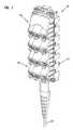
- FIG. 1is a perspective view of a terminal having features that are examples of aspects in accordance with the principles of the present disclosure.
- FIG. 2is a perspective view of embodiments of a releasable engagement mechanism having features that are examples of aspects in accordance with the principles of the present disclosure.
- FIG. 3is a perspective view of a base suitable for use with the terminal of FIG. 1 .
- FIG. 4Ais a perspective view of a tool suitable for use with the base of FIG. 3 .
- FIG. 4Bis a perspective view of the tool of FIG. 4A and the base of FIG. 3 .
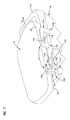
- FIG. 5is a perspective view of an alternate embodiment of a releasable engagement mechanism suitable for use with the terminal of FIG. 1 .
- FIG. 6is a perspective view of an alternate embodiment of a releasable engagement mechanism suitable for use with the terminal of FIG. 1 .
- FIG. 7is a perspective view of an alternate embodiment of a releasable engagement mechanism suitable for use with the terminal of FIG. 1 .
- FIG. 8is a perspective view of an alternate embodiment of the releasable engagement mechanism of FIG. 7 .
- FIG. 9is a perspective view of an alternate embodiment of a releasable engagement mechanism suitable for use with the terminal of FIG. 1 .
- the terminal 10for mounting to a fiber distribution cable 12 is shown.
- the terminal 10includes a housing, generally designated 14 , having a base, generally designated 16 , and a cover, generally designated 18 .
- the releasable engagement mechanism 29includes a resilient latch, generally designated 30 , disposed on an outer perimeter surface 31 of the base 16 .
- the resilient latch 30includes a base end 32 and an oppositely disposed free end 34 .
- the base end 32is in connected engagement with the base 16 .
- the free end 34 of the resilient latch 30extends outwardly from the base 16 in a direction that is generally perpendicular to an outer edge 33 of the base 16 .
- the base end 32 of the resilient latch 30is integral with the base 16 .
- the free end 34includes a lip 36 and a sloped surface 38 .
- the lip 36protrudes outwardly from the outer perimeter surface 31 of the base 16 in a direction that is generally perpendicular to the outer perimeter surface 31 .
- the cover 18includes a catch 40 .
- the catch 40includes an opening 42 adapted to receive the free end 34 of the resilient latch 30 .
- the base 16is aligned with the cover 18 and pressed toward the cover 18 .
- the sloped surface 38 of the resilient latch 30engages an edge 44 of the catch 40 .
- the free end 34 of the resilient latch 30is flexed inwardly toward the base 16 so that the free end 34 extends through the opening 42 of the catch 40 .
- the base 16is pressed toward the cover 18 until the free end 34 of the resilient latch 30 springs back from its flexed position such that the lip 36 engages a back side 46 of the catch 40 .
- the releasable engagement mechanism 229includes a latch 230 having a base end 232 connected to the base 16 and an oppositely disposed free end 234 .
- the latch 230defines an opening 235 disposed between the base end 232 and the free end 234 .
- the opening 235is a square shaped opening. It will be understood, however, that the scope of the present disclosure is not limited to the opening 235 being a square shaped opening.
- the cover 18includes protrusion 240 .
- the protrusion 240includes a lip 242 and a sloped surface 244 .
- the free end 234 of the latch 230engages the sloped surface 244 .
- the free end 234is flexed outwardly from the base 16 until the protrusion 240 extends through the opening 235 in the latch 230 .
- the lip 242 of the protrusion 240engages an edge surface 246 of the opening 235 .
- the releasable engagement mechanism 329includes a latch 330 having a base end 332 connected to the base 16 and an oppositely disposed free end 334 .
- the latch 330defines a plurality of openings 335 disposed between the base end 332 and the free end 334 .
- the opening 335is a square shaped opening.
- Each of the openings 335is adapted for engagement with a protrusion 240 (shown in FIG. 2 ) disposed on the cover 18 .
- the tool 401includes a body portion 403 having a first end portion 405 and an oppositely disposed second end portion 407 .
- the body portion 403further includes a longitudinal axis 409 (shown as a dashed line in FIG. 4A ).
- a handle portion 411is in connected engagement with the body portion 403 at the first end portion 405 .
- the handle portion 411is integral with the body portion 403 .
- the handle portion 411extends outwardly from the body portion 403 .
- the handle portion 411extends outwardly from the body portion 403 at an oblique angle ⁇ . It will be understood, however, that the subject embodiment is not limited to the handle portion 411 extending outwardly from the body portion 403 at an oblique angle ⁇ .
- a release portion 413is in connected engagement with the body portion 403 at the second end portion 407 .
- the release portion 413extends outwardly from the body portion 403 in a direction that is generally perpendicular to the longitudinal axis 409 .
- the release portion 413includes an edge 415 disposed on an inner surface 417 of the release portion 413 .
- the edge 415is generally wedge shaped.
- the edge 415 of the releasing portion 413 of the releasing tool 401is inserted between the free end 334 of the latch 330 and the cover 18 . With the edge 415 inserted between the free end 334 of the latch 330 and the cover 18 , the releasing tool 401 is positioned such that the body portion 403 is adjacent to the latch 330 and the handle portion 411 is positioned above the base 16 . The handle portion 411 is then pressed downward toward the base 16 in a direction “D” (shown as an arrow in FIG. 4B ).
- the handle portion 411As the handle portion 411 is pressed downward, the first end portion 405 of the body portion 403 engages an edge portion 419 of the latch 330 causing the releasing portion 413 to move in an outwardly direction from the cover 18 . As the releasing portion 413 moves outwardly with respect to the cover 18 , the edge 415 flexes the free end 334 of the latch 330 in an outwardly direction relative to the cover 18 . The handle portion 411 is pressed downwardly until an edge surface 336 of each of the openings 335 is disengaged from the lips 242 of the protrusions 240 . When the edge surfaces 336 of the openings 335 of the latch 330 are disengaged from the lips 242 of the protrusion 240 , the base 16 can be removed from the cover 18 .
- the releasable engagement mechanism 429includes a resilient latch, generally designated 430 , having a base end 432 in connected engagement with the outer perimeter surface 31 of the base 16 and an oppositely disposed free end 434 .
- the free end 434extends outwardly from the base 16 in a direction that is generally perpendicular to the outer edge 33 of the base 16 .
- the free end 434includes a lip 436 and a sloped surface 438 .
- the lip 436extends inwardly toward the base 16 in a direction that is generally perpendicular to the outer perimeter surface 31 of the base 16 .
- the resilient latch 430is adapted for engagement with the catch 40 disposed on the cover 18 .
- the resilient latch 430is adapted for engagement with an edge portion 450 of the cover 18 .
- the releasable engagement mechanism 529includes a base protrusion 517 disposed on each longitudinal side 519 of a base 516 such that the base protrusion 517 extends outwardly from the longitudinal side 519 .
- the base protrusion 517defines a groove 521 that opens towards a rear side 523 of the base 516 .
- the groove 521is wedge shaped. It will be understood, however, that the scope of the present disclosure is not limited to the groove 521 being wedge shaped.
- a cover protrusion 525is disposed on each longitudinal side 527 of a cover 518 such that the cover protrusion 525 extends outwardly from the longitudinal side 527 .
- the cover protrusion 525defines a groove 531 that opens towards an outer surface 520 of the cover 518 .
- the groove 531is wedge shaped. It will be understood, however, that the scope of the present disclosure is not limited to the groove 531 being wedge shaped.
- the base protrusion 517 and the cover protrusion 525cooperatively define a protrusion 533 when the base 516 and the cover 518 are properly aligned.
- the protrusion 533has a dove-tailed configuration. It will be understood, however, that the scope of the present disclosure is not limited to the protrusion 533 having a dove-tailed configuration.
- a retainer 535is adapted for sliding engagement with the protrusion 533 defined by the base protrusion 517 and the cover protrusion 525 .
- the length of the retainer 535is generally the length of the protrusion 533 .
- the retainer 535includes a cavity 537 that extends along the longitudinal length of the retainer 535 .
- the cavity 537is adapted to receive the protrusion 533 . In the subject embodiment, therefore, the cavity 537 is dove-tail shaped.
- the cavity 537 in the retainer 535is aligned with the protrusion 533 .
- the retainer 535then slides over the protrusion 533 in a longitudinal direction “L” (shown as an arrow in FIG. 5 ). With the protrusion 533 disposed in the cavity 537 of the retainer 535 , the base 516 and the cover 518 are securely engaged.
- the releasable engagement mechanism 629includes a frame 617 .
- the frame 617is a U-shaped frame having a first leg 619 which is connected to a cross-bar 621 and a second leg 623 oppositely disposed from the first leg 619 on the cross-bar 621 .
- An opening 625is defined between the first leg 619 and the second leg 623 .
- the opening 625 of the frame 617is adapted to receive the base 16 . While the frame 617 is shown as being separate from the base 16 , it will be understood that the scope of the present disclosure is not limited to the frame 617 being separate from the base 16 as the frame 617 could be integral with the base 16 .
- the first and second legs 619 , 623 of the frame 617include an end 627 .
- the end 627is hook-shaped.
- the end 627defines a slot 631 having a slot opening 633 .
- the cover 18includes pins 635 .
- the pin 635is adapted to be received in the slot 631 through the slot opening 633 of the end 627 of the frame 617 .
- the frame 617further includes a plurality of supports 639 .
- Two of the supports 639 a , 639 bare connectedly engaged with the first and second legs 619 , 623 and extend across the opening 625 in a direction that is generally perpendicular to the first and second legs 619 , 623 .
- the third support 639 cis connectedly engaged with the first and second legs 619 , 623 and the cross-bar 621 .
- the third support 639 cincludes a plurality of holes.
- the plurality of holes in the third support 639 care aligned with holes in the base 16 and the cover 18 .
- Fasteners 641e.g., bolts, screws, etc.
- the base 16includes a latch 701 disposed on the outer perimeter surface 20 .
- the latch 701includes a base end 703 and an oppositely disposed free end 705 .
- a portion of the base end 703is connectedly engaged with the base 16 .
- the portion of the base end 703is integral with the base 16 .
- the base end 703 of the latch 701extends outwardly from the base 16 in a direction that is generally perpendicular to an inner side 707 of the base 16 .
- the base end 703includes a longitudinal axis 709 (shown as a dashed line in FIG. 7 ) that extends longitudinally through the base end 703 .
- the free end 705extends outwardly from the base end 703 in a direction that is generally perpendicular to the longitudinal axis 709 .
- the free end 705 of the latch 701includes a sloped surface 710
- the catch 711is connectedly engaged with the cover 18 and disposed near a rear surface 713 of the cover 18 on a peripheral surface 715 .
- the catch 711defines a first side 717 , an oppositely disposed second side 719 , and a connecting side 721 that is connectedly engaged with the first and second sides 717 , 719 .
- the peripheral surface 715 of the cover 18 and the first, second, and connecting sides 717 , 719 , 721 of the catch 711define a latch opening 723 through the catch 711 .
- the latch opening 723is adapted for engagement with the latch 701 disposed on the base 16 .
- the inner side 707 of the base 16is mated to the rear surface 713 of the cover 18 such that the base 16 is offset from the cover 18 .
- the free end 705 of the latch 701is positioned adjacent to the latch opening 723 of the catch 711 .
- the base 16is then moved in a longitudinal direction “L 2 ” (shown as an arrow in FIG. 7 ) relative to the cover 18 .
- L 2a longitudinal direction
- the sloped surface 710 of the latch 701engages the second side 719 of the catch 711 .
- one latch 701is disposed on the outer perimeter surface 20 of the base 16 and another latch 701 is disposed on the peripheral surface 715 of the cover 18 .
- the latches 701are oriented on the base 16 and the cover 18 to allow for engagement between the latch 701 on the base 16 and the latch 701 on the cover 18 .
- the latch 701 on the base 16 and the latch 701 on the cover 18are generally similar. It will be understood, however, that the scope of the present disclosure is not limited to the latch 701 on the base 16 and the latch 701 on the cover 18 being generally similar.
- the releasable latch mechanism 729 ′is engaged by moving the base 16 in the longitudinal direction L 2 relative to the cover 18 .
- the sloped surface 710 of the latch 701 disposed on the base 16engages the sloped surface 710 of the latch 701 disposed on the cover 18 .
- the engagement of the sloped surfaces 710 of the latches 701pulls the base 16 closer to the cover 18 in order to establish a close-fit engagement between the inner side 707 of the base 16 and the rear surface 713 of the cover 18 .
- the cover 18includes a resilient protrusion 801 .
- the resilient protrusion 801includes a base portion 803 and a free portion 805 .
- the base portion 803is connectedly engaged with a rear peripheral surface 807 of the cover 18 such that the base portion 803 extends outwardly from the rear peripheral surface 807 in a generally perpendicular direction.
- the free portion 805extends outwardly from the base portion 803 such that the base and free portions 803 , 805 of the resilient protrusion 801 and the rear peripheral surface 807 of the cover 18 define a gap 809 having an open end 811 .
- the free portion 805includes an inner surface, generally designated 813 , that faces the gap 809 and the rear peripheral surface 807 of the cover 18 .
- the inner surface 813includes a first sloped surface 815 and an oppositely inclined second sloped surface 817 .
- a plateau surface 819is disposed between the first and second sloped surfaces 815 , 817 .
- An inner surface 821 of the base 16includes an outer peripheral edge surface 822 that defines an opening 823 having a thru portion 825 and a latch portion 827 .
- the thru portion 825 of the opening 823extends through the outer peripheral surface 821 of the base 16 .
- the thru portion 825is sized slightly larger than the resilient protrusion 801 of the cover 18 .
- the latch portion 827includes a lip 831 protruding inwardly from the outer peripheral edge surface 822 in a generally perpendicular direction such that the lip 831 extends into a portion of the opening 823 .
- the lip 831 and a side 833 of the opening 823 adjacent to the latch portion 827define a space 835 disposed between the lip 831 and the side 833 .
- the base 16is aligned with the cover 18 such that the rear protrusion 801 of the cover 18 extends into the thru portion 825 of the opening 823 of the base 16 .
- the base 16is moved in a longitudinal direction L 3 (shown as an arrow in FIG. 8 ) relative to the cover 18 .
- the first sloped surface 815 of the free portion 805 of the resilient protrusion 801engages an outer edge 837 of the lip 831 of the latch portion 827 of the opening 823 .
- the free portion 805flexes outwardly in a direction “F.”
- the base 16is moved in the longitudinal direction L 3 until the lip 831 is positioned between the base portion 803 and the second sloped surface 817 .
- the base 16 of the terminal 10includes a top side 901 , a bottom side 903 , a left side 905 and a right side 907 .
- a first hinge component 909is disposed on the bottom side 903 of the base 16 .
- the first hinge component 909includes a base end protrusion 911 that is connectedly engaged with the bottom side 903 of the base 16 such that the base end protrusion 911 extends outwardly from the bottom side 903 in a generally perpendicular direction.
- the first hinge component 909further includes a free end protrusion 913 that extends outwardly from the base end protrusion 911 .
- the free end protrusion 913extends outwardly in a direction that is generally perpendicular to the base end protrusion 911 .
- the bottom side 903 of the base and the base and free end protrusions 911 , 913 of the first hinge component 909cooperatively define a hinge opening 915 having an open end 917 .
- the first hinge component 909is L-shaped. It will be understood, however, that the scope of the present disclosure is not limited to the first hinge component 909 being L-shaped.
- the cover 18includes a top end 919 and an oppositely disposed bottom end 921 .
- a second hinge component 923extends outwardly from a rear surface 925 of the cover 18 at the bottom end 921 .
- the second hinge component 923is hook shaped having a first leg portion 927 and a second leg portion 931 and a connection portion 933 in connected engagement with the first and second leg portions 927 , 931 .
- the first and second leg portion 927 , 931 and the connection portion 933cooperatively define a hinge slot 935 having a hinge slot opening 937 .
- the hinge slot 935is adapted to receive the free end protrusion 913 of the first hinge component 909 .
- the base 16is oriented with respect to the cover 18 such that the free end portion 913 of the first hinge component 909 is positioned at the hinge slot opening 937 of the second hinge component.
- the distance between the top side 901 of the base 16 and the top end 919 of the cover 18is greater than the distance between the bottom side 903 of the base 16 and the bottom end 921 of the cover 18 .
- the free end portion 913 of the first hinge component 909positioned for insertion into the hinge slot 935 of the second hinge component 923 , the distance between the top side 901 of the base 16 and the top end 919 of the cover 18 is reduced by moving the base 16 in a downward direction D 2 (shown as an arrow in FIG.
- a plurality of latches or resilient latches similar to the ones described aboveare disposed on the top side 901 of the base 16 and/or the top end 919 of the cover 18 for connectedly engaging the top side 901 of the base 16 to the top end 919 of the cover 18 . It will be understood, however, that the scope of the present disclosure is not limited to the top side 901 of the base 16 or the top end 919 of the cover 18 having latches as fasteners could also be used for releasable engagement of the top side 901 and the top end 919 .
Landscapes
- Physics & Mathematics (AREA)
- General Physics & Mathematics (AREA)
- Optics & Photonics (AREA)
- Light Guides In General And Applications Therefor (AREA)
Abstract
Description
Claims (5)
Priority Applications (1)
| Application Number | Priority Date | Filing Date | Title |
|---|---|---|---|
| US12/248,612US7903923B2 (en) | 2007-10-09 | 2008-10-09 | Drop terminal releasable engagement mechanism |
Applications Claiming Priority (2)
| Application Number | Priority Date | Filing Date | Title |
|---|---|---|---|
| US97864207P | 2007-10-09 | 2007-10-09 | |
| US12/248,612US7903923B2 (en) | 2007-10-09 | 2008-10-09 | Drop terminal releasable engagement mechanism |
Publications (2)
| Publication Number | Publication Date |
|---|---|
| US20090123115A1 US20090123115A1 (en) | 2009-05-14 |
| US7903923B2true US7903923B2 (en) | 2011-03-08 |
Family
ID=40623782
Family Applications (1)
| Application Number | Title | Priority Date | Filing Date |
|---|---|---|---|
| US12/248,612ActiveUS7903923B2 (en) | 2007-10-09 | 2008-10-09 | Drop terminal releasable engagement mechanism |
Country Status (1)
| Country | Link |
|---|---|
| US (1) | US7903923B2 (en) |
Cited By (28)
| Publication number | Priority date | Publication date | Assignee | Title |
|---|---|---|---|---|
| US10359577B2 (en) | 2017-06-28 | 2019-07-23 | Corning Research & Development Corporation | Multiports and optical connectors with rotationally discrete locking and keying features |
| US20190237898A1 (en)* | 2016-07-20 | 2019-08-01 | Hirose Electric Co., Ltd. | Cable connector having cable holders |
| US10379298B2 (en) | 2017-06-28 | 2019-08-13 | Corning Research & Development Corporation | Fiber optic connectors and multiport assemblies including retention features |
| US10641967B1 (en) | 2018-11-16 | 2020-05-05 | Corning Research & Development Corporation | Multiport assemblies including a modular adapter support array |
| US10768382B2 (en) | 2018-11-29 | 2020-09-08 | Corning Research & Development Corporation | Multiport assemblies including access apertures and a release tool |
| US11073670B2 (en) | 2016-08-12 | 2021-07-27 | Corning Optical Communications LLC | Device and method for sealing multiport splitters |
| WO2021217079A1 (en) | 2020-04-24 | 2021-10-28 | Commscope Technologies Llc | Fiber routing systems and methods |
| US11187859B2 (en) | 2017-06-28 | 2021-11-30 | Corning Research & Development Corporation | Fiber optic connectors and methods of making the same |
| US11294133B2 (en) | 2019-07-31 | 2022-04-05 | Corning Research & Development Corporation | Fiber optic networks using multiports and cable assemblies with cable-to-connector orientation |
| US11300746B2 (en) | 2017-06-28 | 2022-04-12 | Corning Research & Development Corporation | Fiber optic port module inserts, assemblies and methods of making the same |
| US11460657B2 (en) | 2020-04-30 | 2022-10-04 | Commscope Technologies Llc | Fiber management system and method for a telecommunication terminal |
| US11487073B2 (en) | 2019-09-30 | 2022-11-01 | Corning Research & Development Corporation | Cable input devices having an integrated locking feature and assemblies using the cable input devices |
| US11536921B2 (en) | 2020-02-11 | 2022-12-27 | Corning Research & Development Corporation | Fiber optic terminals having one or more loopback assemblies |
| US11604320B2 (en) | 2020-09-30 | 2023-03-14 | Corning Research & Development Corporation | Connector assemblies for telecommunication enclosures |
| US11650388B2 (en) | 2019-11-14 | 2023-05-16 | Corning Research & Development Corporation | Fiber optic networks having a self-supporting optical terminal and methods of installing the optical terminal |
| US11668890B2 (en) | 2017-06-28 | 2023-06-06 | Corning Research & Development Corporation | Multiports and other devices having optical connection ports with securing features and methods of making the same |
| US11686913B2 (en) | 2020-11-30 | 2023-06-27 | Corning Research & Development Corporation | Fiber optic cable assemblies and connector assemblies having a crimp ring and crimp body and methods of fabricating the same |
| US11880076B2 (en) | 2020-11-30 | 2024-01-23 | Corning Research & Development Corporation | Fiber optic adapter assemblies including a conversion housing and a release housing |
| US11886010B2 (en) | 2019-10-07 | 2024-01-30 | Corning Research & Development Corporation | Fiber optic terminals and fiber optic networks having variable ratio couplers |
| US11927810B2 (en) | 2020-11-30 | 2024-03-12 | Corning Research & Development Corporation | Fiber optic adapter assemblies including a conversion housing and a release member |
| US11947167B2 (en) | 2021-05-26 | 2024-04-02 | Corning Research & Development Corporation | Fiber optic terminals and tools and methods for adjusting a split ratio of a fiber optic terminal |
| US11953750B2 (en) | 2020-04-30 | 2024-04-09 | Commscope Technologies Llc | Interlocking fiber optic connector holder |
| US11994722B2 (en) | 2020-11-30 | 2024-05-28 | Corning Research & Development Corporation | Fiber optic adapter assemblies including an adapter housing and a locking housing |
| US12019279B2 (en) | 2019-05-31 | 2024-06-25 | Corning Research & Development Corporation | Multiports and other devices having optical connection ports with sliding actuators and methods of making the same |
| US12044894B2 (en) | 2018-12-28 | 2024-07-23 | Corning Research & Development Corporation | Multiport assemblies including mounting features or dust plugs |
| US12271040B2 (en) | 2017-06-28 | 2025-04-08 | Corning Research & Development Corporation | Fiber optic extender ports, assemblies and methods of making the same |
| US12372727B2 (en) | 2020-10-30 | 2025-07-29 | Corning Research & Development Corporation | Female fiber optic connectors having a rocker latch arm and methods of making the same |
| US12422636B2 (en) | 2021-12-17 | 2025-09-23 | Commscope Technologies Llc | Fiber routing system with direct PLC chip termination |
Families Citing this family (9)
| Publication number | Priority date | Publication date | Assignee | Title |
|---|---|---|---|---|
| US7903923B2 (en) | 2007-10-09 | 2011-03-08 | Adc Telecommunications, Inc. | Drop terminal releasable engagement mechanism |
| EP2198328B1 (en) | 2007-10-09 | 2018-09-26 | ADC Telecommunications, INC. | Mini drop terminal |
| US20110097052A1 (en)* | 2009-10-21 | 2011-04-28 | Solheid James J | Fiber Access Terminal Mounted at a Mid-Span Access Location of a Telecommunications Cable |
| NL2014263B1 (en)* | 2015-02-09 | 2016-10-13 | Genexis Holding Bv | Fiber connection assembly. |
| USD831578S1 (en)* | 2016-10-28 | 2018-10-23 | Corning Optical Communications LLC | Fiber optic closure |
| MX2020005413A (en) | 2017-11-28 | 2020-10-28 | Commscope Technologies Llc | Indicia and method for identifying telecommunications components. |
| EP3776748A4 (en) | 2018-03-29 | 2022-01-26 | CommScope Technologies LLC | SIGNS AND METHODS OF IDENTIFICATION OF TELECOMMUNICATIONS COMPONENTS |
| USD916044S1 (en) | 2018-10-19 | 2021-04-13 | Commscope Technologies Llc | Telecommunications enclosure |
| USD935428S1 (en)* | 2019-04-19 | 2021-11-09 | Commscope Technologies Llc | Telecommunications identification plate |
Citations (165)
| Publication number | Priority date | Publication date | Assignee | Title |
|---|---|---|---|---|
| US4453291A (en) | 1982-06-21 | 1984-06-12 | Harvey Hubbell Incorporated | Grip for pulling fiber optic cable |
| US4478486A (en) | 1982-08-12 | 1984-10-23 | Raychem Corporation | Fiber optic splice organizer |
| US4648168A (en) | 1983-12-19 | 1987-03-10 | N.V. Raychem S.A. | Optical fibre breakout |
| US4652072A (en) | 1986-04-28 | 1987-03-24 | Wire Tech Incorporated | Cable-connector assembly |
| US4684221A (en) | 1985-01-16 | 1987-08-04 | Olympus Optical Co., Ltd. | Graded refractive index single lens system |
| US4685764A (en) | 1985-02-01 | 1987-08-11 | Amp Incorporated | Splice organizer for optical cable splices |
| US4717231A (en) | 1983-01-05 | 1988-01-05 | Vincent Dewez | Interconnecting and distributing box for optical fibers |
| US4744622A (en) | 1986-09-12 | 1988-05-17 | Amp Incorporated | Optical fiber splice case |
| US4761052A (en) | 1986-01-31 | 1988-08-02 | N. V. Raychem S.A. | Optical fibre splice case |
| EP0293183A2 (en) | 1987-05-26 | 1988-11-30 | Minnesota Mining And Manufacturing Company | Optical fiber distribution panel |
| US4805979A (en) | 1987-09-04 | 1989-02-21 | Minnesota Mining And Manufacturing Company | Fiber optic cable splice closure |
| US4838643A (en) | 1988-03-23 | 1989-06-13 | Alcatel Na, Inc. | Single mode bend insensitive fiber for use in fiber optic guidance applications |
| US4908482A (en) | 1987-12-08 | 1990-03-13 | Raychem Corporation | Cable closure |
| US4911662A (en) | 1988-12-20 | 1990-03-27 | Northern Telecom Limited | Distribution frame for telecommunications cable |
| US4913522A (en) | 1984-04-11 | 1990-04-03 | Nv Raychem Sa | Electrofit fibre optics butt splice |
| US4958903A (en) | 1988-12-09 | 1990-09-25 | At&T Bell Laboratories | Splice closure |
| US4986762A (en) | 1989-08-15 | 1991-01-22 | Minnesota Mining And Manufacturing Company | Termination module for use in an array of modules |
| US5029958A (en) | 1989-04-28 | 1991-07-09 | Scientific-Atlanta, Inc. | Optical fiber enclosure for optoelectronic converter |
| US5046811A (en) | 1989-07-17 | 1991-09-10 | Jung Roger E | Junction box for optical communications cords, and gland assembly for cord |
| US5048916A (en) | 1982-09-07 | 1991-09-17 | Amp Incorporated | Fiber optic connection system |
| US5076656A (en)* | 1984-06-08 | 1991-12-31 | Briggs Robert C | High precision optical fiber connectors |
| US5097530A (en) | 1991-04-04 | 1992-03-17 | Raychem Corporation | Optical fiber enclosure including novel retaining ring |
| US5097529A (en) | 1991-03-22 | 1992-03-17 | At&T Bell Laboratories | Space-saving optical fiber cable closure |
| US5122069A (en) | 1989-07-28 | 1992-06-16 | Amp Incorporated | Access flooring module |
| US5129030A (en) | 1991-05-30 | 1992-07-07 | At&T Bell Laboratories | Movable lightguide connector panel |
| US5133038A (en) | 1980-04-17 | 1992-07-21 | Reliance Comm/Tec. Corporation | Fiber optic splice case |
| US5133039A (en) | 1990-10-29 | 1992-07-21 | At&T Bell Laboratories | Aerial fiber optic cable case |
| EP0511147A1 (en) | 1991-04-22 | 1992-10-28 | Telefonica De Espana, S.A. | Universal access optical fiber junction box |
| US5185845A (en) | 1990-12-13 | 1993-02-09 | At&T Bell Laboratories | Optical fiber closure having enhanced storage capability |
| US5208893A (en) | 1992-05-21 | 1993-05-04 | Raynet Corporation | Optical fiber splice tray and splice holder |
| US5212761A (en) | 1992-04-27 | 1993-05-18 | At&T Bell Laboratories | Fiber optic module |
| US5214735A (en) | 1992-04-06 | 1993-05-25 | Adc Telecommunications, Inc. | Fiber optic connector retainer |
| US5222183A (en) | 1988-11-07 | 1993-06-22 | N.V. Raychem S.A. | Splice case for optical fibre cable |
| US5231687A (en) | 1990-06-04 | 1993-07-27 | Bicc Plc | Termination system for optical fibres |
| US5235665A (en) | 1991-05-06 | 1993-08-10 | Sirti S.P.A. | Branching device for fibre-optic cables |
| US5249253A (en) | 1984-04-11 | 1993-09-28 | Nv Raychem Sa | Electrofit fibre optics butt splice |
| US5267122A (en) | 1992-06-15 | 1993-11-30 | Alcatel Network Systems, Inc. | Optical network unit |
| US5278931A (en) | 1992-12-31 | 1994-01-11 | Corning Incorporated | Low bend loss singlemode optical waveguide fiber |
| US5323480A (en) | 1992-11-25 | 1994-06-21 | Raychem Corporation | Fiber optic splice closure |
| US5363465A (en) | 1993-02-19 | 1994-11-08 | Adc Telecommunications, Inc. | Fiber optic connector module |
| US5367598A (en) | 1993-10-21 | 1994-11-22 | Nec America, Inc. | Interface chassis for fiber optic transport system |
| US5396575A (en) | 1992-12-18 | 1995-03-07 | Raynet Corporation | Sealed optical fiber closures |
| USRE34955E (en) | 1989-07-31 | 1995-05-30 | Adc Telecommunications, Inc. | Optical fiber distribution frame |
| US5439395A (en) | 1993-08-30 | 1995-08-08 | At&T Corp. | DSX jack |
| US5446823A (en) | 1994-01-26 | 1995-08-29 | Raychem Corporation | Aerial, pedestal, below grade, or buried optical fiber closure |
| US5479553A (en) | 1993-04-19 | 1995-12-26 | Raychem Corporation | Fiber optic splice closure |
| US5479533A (en) | 1992-02-28 | 1995-12-26 | Yamatake-Honeywell Co., Ltd. | Pattern recognition apparatus and method using fuzzy logic |
| US5480203A (en) | 1994-01-18 | 1996-01-02 | Hubbell Incorporated | Pulling tool for pulling connectorized cable |
| US5509099A (en) | 1995-04-26 | 1996-04-16 | Antec Corp. | Optical fiber closure with sealed cable entry ports |
| US5525756A (en) | 1994-02-28 | 1996-06-11 | Raychem Corporation | Rodent-proof aerial splice closure |
| US5530787A (en) | 1995-02-28 | 1996-06-25 | At&T Corp | Optical fiber guide for preventing sharp bends |
| US5535298A (en) | 1995-01-30 | 1996-07-09 | The Whitaker Corporation | Pedestal for fiber optic cable |
| US5546495A (en) | 1993-04-16 | 1996-08-13 | The Whitaker Corporation | Splice tray rack and cabinet for fiber optic cables |
| USD372897S (en) | 1995-04-17 | 1996-08-20 | Raychem Corporation | Fiber optic splice tray |
| US5566269A (en) | 1995-05-30 | 1996-10-15 | The Whitaker Corporation | Strain relieving holder for optical fiber cable |
| US5566268A (en) | 1995-05-30 | 1996-10-15 | The Whitaker Corporation | Strain relieving holder for optical fiber cable |
| US5577151A (en) | 1995-08-15 | 1996-11-19 | The Whitaker Corporation | Optical fiber splice tray and cover |
| US5602954A (en) | 1984-04-11 | 1997-02-11 | Raychem Sv | Electrofit fiber optics butt splice |
| US5613030A (en) | 1995-05-15 | 1997-03-18 | The Whitaker Corporation | High density fiber optic interconnection enclosure |
| US5633973A (en) | 1994-12-08 | 1997-05-27 | Alcatel Cable Interface | Splice box for splicing together opticl-fiber cables |
| US5634822A (en) | 1994-11-14 | 1997-06-03 | Augat Inc. | Miniature telephone jack and rack system |
| US5640482A (en) | 1995-08-31 | 1997-06-17 | The Whitaker Corporation | Fiber optic cable management rack |
| US5647045A (en)* | 1996-02-23 | 1997-07-08 | Leviton Manufacturing Co., Inc. | Multi-media connection housing |
| US5659650A (en) | 1995-09-26 | 1997-08-19 | Lucent Technologies Inc. | Hinged faceplate |
| US5661841A (en) | 1993-09-08 | 1997-08-26 | Raychem Limited | Optical fibre organizer having fibre storing means |
| EP0805536A1 (en) | 1996-05-01 | 1997-11-05 | Bowthorpe Plc | Cable enclosure |
| US5689607A (en) | 1994-12-08 | 1997-11-18 | Alcatel Cable Interface | Device for holding at least one optical fiber cable, and a splice box making use of the device |
| US5701380A (en) | 1996-06-24 | 1997-12-23 | Telect, Inc. | Fiber optic module for high density supply of patching and splicing |
| US5732180A (en) | 1995-06-09 | 1998-03-24 | Multilink, Inc. | Method and apparatus for sealing fiber optic entryways to a sealed enclosure |
| US5734776A (en) | 1996-08-28 | 1998-03-31 | Adc Telecommunications, Inc. | Outside plant cross-connect apparatus |
| US5745633A (en) | 1996-12-24 | 1998-04-28 | Siecor Corporation | Fiber optic cable assembly for securing a fiber optic cable within an input port of a splice closure |
| US5754723A (en) | 1993-07-08 | 1998-05-19 | Raychem Gmbh | Multi-filament splice enclosures |
| US5758004A (en) | 1995-03-31 | 1998-05-26 | Minnesota Mining And Manufacturing Company | Closure with cable strain relief |
| US5758003A (en) | 1996-03-15 | 1998-05-26 | Adc Telecommunications, Inc. | High density fiber management |
| EP0844504A2 (en) | 1996-11-21 | 1998-05-27 | RXS Kabelgarnituren Gesellschaft mit beschränkter Haftung | Connection box for optical cables |
| US5764843A (en) | 1993-09-08 | 1998-06-09 | N.V. Raychem S.A. | Optical fibre organizer |
| US5764844A (en) | 1994-03-21 | 1998-06-09 | N.V. Raychem S.A. | Splice organizing apparatus |
| EP0851257A1 (en) | 1996-12-31 | 1998-07-01 | Siecor Corporation | Optical fiber connector housing |
| US5778122A (en) | 1996-12-24 | 1998-07-07 | Siecor Corporation | Fiber optic cable assembly for interconnecting optical fibers within a receptacle mounted within the wall of an enclosure |
| US5777268A (en) | 1995-10-06 | 1998-07-07 | Raychem Corporation | Splice closure for buried telecommunications cables |
| US5781678A (en) | 1995-01-25 | 1998-07-14 | Sumitomo Electric Industries, Ltd. | Optical fiber path joint member and method of blowing optical fiber |
| US5790740A (en)* | 1995-04-20 | 1998-08-04 | Preformed Line Products Company | Optical fiber splice case |
| US5825960A (en) | 1996-04-30 | 1998-10-20 | The Whitaker Corporation | Fiber optic management system |
| US5828807A (en) | 1996-04-30 | 1998-10-27 | Next Level Communications | Optical network unit (ONU) mechanical enclosure |
| US5863083A (en) | 1996-11-20 | 1999-01-26 | Siecor Corporation | Pulling grip for pre-connectorized fiber optic cable |
| US5879197A (en) | 1997-11-17 | 1999-03-09 | Adc Telecommunications, Inc. | Jack module |
| US5886300A (en) | 1996-04-30 | 1999-03-23 | The Whitaker Corporation | Plug for a sealing grommet |
| US5892870A (en) | 1995-11-16 | 1999-04-06 | Fiber Connections Inc. | Fibre optic cable connector |
| US5894540A (en) | 1997-05-22 | 1999-04-13 | Lucent Technologies Inc. | Optical Fiber take-up assembly |
| US5903698A (en) | 1997-04-11 | 1999-05-11 | Wiltron Company | Fiber optic connection assembly |
| US5907653A (en) | 1997-05-01 | 1999-05-25 | Lucent Technologies Inc. | Racetrack grommet for optical fiber cable splice closure |
| US5911027A (en) | 1993-09-08 | 1999-06-08 | N.V. Raychem, S.A. | Optical fibre organizer having through port extending between opposite faces thereof |
| US5917648A (en) | 1994-06-22 | 1999-06-29 | Hewlett-Packard Company | Packaged optical amplifier assembly |
| US5933563A (en) | 1997-10-14 | 1999-08-03 | The Whitaker Corporation | Cable enclosure with pass through |
| US5975769A (en) | 1997-07-08 | 1999-11-02 | Telect, Inc. | Universal fiber optic module system |
| US5982971A (en) | 1996-10-10 | 1999-11-09 | Tyco Submarine Systems Ltd. | Floating fiber storage assembly |
| US5995700A (en)* | 1998-01-15 | 1999-11-30 | Lucent Technologies Inc. | Mass fusion splice tray |
| USRE36592E (en) | 1994-07-01 | 2000-02-29 | Siecor Corporation | Optical receiver stub fitting |
| US6160946A (en) | 1998-07-27 | 2000-12-12 | Adc Telecommunications, Inc. | Outside plant fiber distribution apparatus and method |
| US6167183A (en) | 1997-05-30 | 2000-12-26 | Hubbell Incorporated | Low profile communications outlet box |
| US6175079B1 (en) | 1999-06-03 | 2001-01-16 | Tyco Electronics Corporation | Fiber optic cable management system |
| US6208796B1 (en) | 1998-07-21 | 2001-03-27 | Adc Telecommunications, Inc. | Fiber optic module |
| US6215939B1 (en) | 1998-07-02 | 2001-04-10 | Preformed Line Products Company | Optical fiber splice case with integral cable clamp, buffer cable storage area and metered air valve |
| US6250816B1 (en) | 1999-02-19 | 2001-06-26 | Tyco Electronics Corporation | Cable connector plate and method for interconnecting ends of fiber optic cable |
| US6259024B1 (en) | 1999-08-09 | 2001-07-10 | Avaya Technology Corp | Integrated base fixture for a telecommunications enclosure |
| US6263142B1 (en) | 1998-10-07 | 2001-07-17 | Tyco Submarine Systems, Ltd. | Method and apparatus for separating optical fibers |
| US6275639B1 (en) | 1996-08-22 | 2001-08-14 | Sidney Joseph Bolt | Optical fiber splice closure |
| US6275640B1 (en) | 1999-04-21 | 2001-08-14 | Tyco Electrtonics Corporation | Fiber optic splice closure including end pivoting slack storage holder with adjustable rear wall and associated methods |
| US6292614B1 (en) | 1999-08-24 | 2001-09-18 | Siecor Operations, Llc | Movable bracket for holding internal components of an optical fiber interconnection closure during servicing and associated method |
| US6300562B1 (en) | 1999-07-29 | 2001-10-09 | Avaya Technology Corp. | Self-sealing telecommunications enclosure |
| WO2002006879A1 (en) | 2000-07-13 | 2002-01-24 | France Telecom | Box for connecting optical fibres to workstations, for buildings |
| US6396989B1 (en) | 1999-02-19 | 2002-05-28 | Tyco Electronics Corporation | Fiber optic cable retainer assembly and clip with a bend-radius control surface |
| US6424782B1 (en) | 2000-08-15 | 2002-07-23 | Tyco Electronics Corporation | Fiber optic splice closure and method of routing optical fiber ribbons |
| US6439779B1 (en) | 2000-04-20 | 2002-08-27 | Fos Gmbh | System for coupling a lightwave conductor cable on coupling elements of a housing |
| US6453106B1 (en) | 2000-06-30 | 2002-09-17 | Ge-Act Communications, Inc. | Method and apparatus for a cable location and protection system |
| US6476327B1 (en)* | 2000-06-01 | 2002-11-05 | Panduit Corp. | Split fiber cover and raceway fitting |
| US6504987B1 (en) | 1996-11-20 | 2003-01-07 | Tyco Electronics Corporation | Optical fiber organizer |
| US6504986B1 (en) | 1998-01-21 | 2003-01-07 | Tyco Electronics Corporation | Optical fiber assembly |
| US6507691B1 (en) | 1999-03-22 | 2003-01-14 | Tyco Electronics Corporation | Fiber optic splice organizer with splicing tray and associated method |
| US6535682B1 (en) | 1999-03-01 | 2003-03-18 | Adc Telecommunications, Inc. | Optical fiber distribution frame with connector modules |
| US20030072540A1 (en)* | 2001-10-17 | 2003-04-17 | Huang Nan Tsung | Small form factor pluggable optoelectronic transceiver module |
| US20030077041A1 (en) | 2001-10-19 | 2003-04-24 | Belaidi Hakim F. | High-connector density interface plate |
| US20030091315A1 (en)* | 2001-10-25 | 2003-05-15 | Allerellie Michael Wayne | Fiberoptic splice closure |
| US20030103750A1 (en)* | 2001-11-30 | 2003-06-05 | Laporte Richard B. | Distribution terminal for network access point |
| US6575792B2 (en) | 1998-11-12 | 2003-06-10 | Adc Telecommunications, Inc. | Jack assembly |
| US6579014B2 (en) | 2001-09-28 | 2003-06-17 | Corning Cable Systems Llc | Fiber optic receptacle |
| US6648520B2 (en) | 2001-09-28 | 2003-11-18 | Corning Cable Systems Llc | Fiber optic plug |
| US6661961B1 (en) | 2000-11-01 | 2003-12-09 | Tyco Electronics Corporation | Fiber low profile network interface device |
| US20040028368A1 (en) | 2002-05-01 | 2004-02-12 | Tyco Electronics | Fiber management apparatus |
| US20040062508A1 (en)* | 2002-09-27 | 2004-04-01 | Blankenship Aaron I. | Fiber optic network interface device |
| US6728451B2 (en) | 1999-09-21 | 2004-04-27 | Tyco Telecommunications (Us) Inc. | Optical fiber holding structure and method of making same |
| US6760531B1 (en) | 1999-03-01 | 2004-07-06 | Adc Telecommunications, Inc. | Optical fiber distribution frame with outside plant enclosure |
| US6763170B2 (en) | 2001-02-02 | 2004-07-13 | Tyco Telecommunications (Us) Inc. | System for storing splices in a joint box |
| US6766094B2 (en) | 2002-06-28 | 2004-07-20 | Corning Cable Systems Llc | Aerial closure for local convergence point |
| US6804447B2 (en)* | 2002-11-05 | 2004-10-12 | Adc Telecommunications, Inc. | Fiber panel with integrated couplers |
| FR2853775A1 (en) | 2003-04-11 | 2004-10-15 | Symec Gmbh | Equipment tray for installation in ground tanks, has at least one carrier with through opening to which aperture-like adapter is attached on one side at angle to carrier |
| US20040211774A1 (en) | 2003-04-23 | 2004-10-28 | Lucent Technologies Inc. | Fiber closure sealing apparatus |
| US20040240823A1 (en)* | 2003-05-30 | 2004-12-02 | Lucent Technologies Inc. | Optical fiber trough for an optical interconnection system |
| US6880986B2 (en) | 2000-12-08 | 2005-04-19 | Optical Communication Products, Inc. | Optical subassembly enclosure |
| US20050094959A1 (en) | 2003-10-31 | 2005-05-05 | Sibley Keith E. | Fiber optic cable managemetn enclosure and method of use |
| US20050129375A1 (en) | 2003-12-15 | 2005-06-16 | Elkins Robert B.Ii | Pre-connectorized fiber optic distribution cable |
| US20050145522A1 (en) | 2003-12-24 | 2005-07-07 | Bloodworth Stephen G. | Fiber optic drop cable slack storage receptacle |
| US20050163448A1 (en) | 2004-01-27 | 2005-07-28 | Blackwell Chois A.Jr. | Multi-port optical connection terminal |
| US6926449B1 (en) | 2004-02-23 | 2005-08-09 | Corning Cable Systems Llc | Connector port for network interface device |
| US20050175307A1 (en) | 2004-02-06 | 2005-08-11 | Battey Jennifer A. | Optical connection closure having at least one connector port |
| US20050186838A1 (en) | 2004-02-20 | 2005-08-25 | Debenedictis Damon | Methods and systems for positioning connectors to minimize alien crosstalk |
| US20050213921A1 (en) | 2004-03-08 | 2005-09-29 | Mertesdorf Daniel R | Fiber access terminal |
| US6993237B2 (en) | 2003-11-26 | 2006-01-31 | Corning Cable Systems Llc | Pulling grip for installing pre-connectorized fiber optic cable |
| US20060089049A1 (en) | 2004-10-27 | 2006-04-27 | Panduit Corp. | Fiber optic industrial connector |
| US20060093303A1 (en) | 2004-11-03 | 2006-05-04 | Randy Reagan | Fiber drop terminal |
| US7072559B2 (en) | 2004-07-09 | 2006-07-04 | Tyco Telecommunications (Us) Inc. | Multiple hinged tray cable connecting joint and method of using same |
| US20060153517A1 (en) | 2004-11-03 | 2006-07-13 | Randy Reagan | Methods for configuring and testing fiber drop terminals |
| JP2006215248A (en)* | 2005-02-03 | 2006-08-17 | Mitsubishi Cable Ind Ltd | Coding member for optical communication cable and connector connecting structure of optical communication cable |
| US7142764B2 (en) | 2003-03-20 | 2006-11-28 | Tyco Electronics Corporation | Optical fiber interconnect cabinets, termination modules and fiber connectivity management for the same |
| US20060285810A1 (en) | 2003-09-16 | 2006-12-21 | Tyco Electronics Raychem Nv | Protective casing component and an element for forming a protective casing component |
| US20070104448A1 (en) | 2005-10-24 | 2007-05-10 | Tyco Electronics Corporation | Optical fiber clips, random access management systems including clips and methods for using the same |
| US20070189694A1 (en) | 2005-07-25 | 2007-08-16 | Tyco Electronics Corporation | Optical fiber cable termination apparatus |
| US7263265B2 (en) | 2004-05-11 | 2007-08-28 | Preformed Line Products Company | Convertible fiber closure platform |
| US7300215B2 (en)* | 2004-06-04 | 2007-11-27 | Industrial Technology Research Institute | Light transceiver module |
| US7340145B2 (en) | 2005-10-24 | 2008-03-04 | Tyco Electronics Corporation | Fiber optic splice storage apparatus and methods for using the same |
| WO2008118603A2 (en) | 2007-03-23 | 2008-10-02 | Adc Telecommunications, Inc. | Drop terminal with anchor block for retaining a stub cable |
| US7492996B2 (en) | 2005-06-21 | 2009-02-17 | Adc Telecommunications, Inc. | Grounding device for armored cable |
| US20090123115A1 (en) | 2007-10-09 | 2009-05-14 | Erik Gronvall | Drop Terminal Releasable Engagement Mechanism |
| US20090148118A1 (en) | 2007-10-09 | 2009-06-11 | Erik Gronvall | Mini Drop Terminal |
| US7591595B2 (en) | 2007-01-24 | 2009-09-22 | Adc Telelcommunications, Inc. | Hardened fiber optic adapter |
- 2008
- 2008-10-09USUS12/248,612patent/US7903923B2/enactiveActive
Patent Citations (190)
| Publication number | Priority date | Publication date | Assignee | Title |
|---|---|---|---|---|
| US5133038A (en) | 1980-04-17 | 1992-07-21 | Reliance Comm/Tec. Corporation | Fiber optic splice case |
| US4453291A (en) | 1982-06-21 | 1984-06-12 | Harvey Hubbell Incorporated | Grip for pulling fiber optic cable |
| US4478486A (en) | 1982-08-12 | 1984-10-23 | Raychem Corporation | Fiber optic splice organizer |
| US5048916A (en) | 1982-09-07 | 1991-09-17 | Amp Incorporated | Fiber optic connection system |
| US4717231A (en) | 1983-01-05 | 1988-01-05 | Vincent Dewez | Interconnecting and distributing box for optical fibers |
| US4648168A (en) | 1983-12-19 | 1987-03-10 | N.V. Raychem S.A. | Optical fibre breakout |
| US5155794A (en) | 1984-04-11 | 1992-10-13 | Raychem Corporation | Electrofit fibre optics butt splice |
| US4913522A (en) | 1984-04-11 | 1990-04-03 | Nv Raychem Sa | Electrofit fibre optics butt splice |
| US5249253A (en) | 1984-04-11 | 1993-09-28 | Nv Raychem Sa | Electrofit fibre optics butt splice |
| US5602954A (en) | 1984-04-11 | 1997-02-11 | Raychem Sv | Electrofit fiber optics butt splice |
| US5076656A (en)* | 1984-06-08 | 1991-12-31 | Briggs Robert C | High precision optical fiber connectors |
| US4684221A (en) | 1985-01-16 | 1987-08-04 | Olympus Optical Co., Ltd. | Graded refractive index single lens system |
| US4685764A (en) | 1985-02-01 | 1987-08-11 | Amp Incorporated | Splice organizer for optical cable splices |
| US4761052A (en) | 1986-01-31 | 1988-08-02 | N. V. Raychem S.A. | Optical fibre splice case |
| US4652072A (en) | 1986-04-28 | 1987-03-24 | Wire Tech Incorporated | Cable-connector assembly |
| US4744622A (en) | 1986-09-12 | 1988-05-17 | Amp Incorporated | Optical fiber splice case |
| EP0293183A2 (en) | 1987-05-26 | 1988-11-30 | Minnesota Mining And Manufacturing Company | Optical fiber distribution panel |
| US4805979A (en) | 1987-09-04 | 1989-02-21 | Minnesota Mining And Manufacturing Company | Fiber optic cable splice closure |
| US4908482A (en) | 1987-12-08 | 1990-03-13 | Raychem Corporation | Cable closure |
| US4838643A (en) | 1988-03-23 | 1989-06-13 | Alcatel Na, Inc. | Single mode bend insensitive fiber for use in fiber optic guidance applications |
| US5222183A (en) | 1988-11-07 | 1993-06-22 | N.V. Raychem S.A. | Splice case for optical fibre cable |
| US4958903A (en) | 1988-12-09 | 1990-09-25 | At&T Bell Laboratories | Splice closure |
| US4911662A (en) | 1988-12-20 | 1990-03-27 | Northern Telecom Limited | Distribution frame for telecommunications cable |
| US5029958A (en) | 1989-04-28 | 1991-07-09 | Scientific-Atlanta, Inc. | Optical fiber enclosure for optoelectronic converter |
| US5046811A (en) | 1989-07-17 | 1991-09-10 | Jung Roger E | Junction box for optical communications cords, and gland assembly for cord |
| US5122069A (en) | 1989-07-28 | 1992-06-16 | Amp Incorporated | Access flooring module |
| USRE34955E (en) | 1989-07-31 | 1995-05-30 | Adc Telecommunications, Inc. | Optical fiber distribution frame |
| US4986762A (en) | 1989-08-15 | 1991-01-22 | Minnesota Mining And Manufacturing Company | Termination module for use in an array of modules |
| US5231687A (en) | 1990-06-04 | 1993-07-27 | Bicc Plc | Termination system for optical fibres |
| US5133039A (en) | 1990-10-29 | 1992-07-21 | At&T Bell Laboratories | Aerial fiber optic cable case |
| US5185845A (en) | 1990-12-13 | 1993-02-09 | At&T Bell Laboratories | Optical fiber closure having enhanced storage capability |
| US5097529A (en) | 1991-03-22 | 1992-03-17 | At&T Bell Laboratories | Space-saving optical fiber cable closure |
| US5097530A (en) | 1991-04-04 | 1992-03-17 | Raychem Corporation | Optical fiber enclosure including novel retaining ring |
| EP0511147A1 (en) | 1991-04-22 | 1992-10-28 | Telefonica De Espana, S.A. | Universal access optical fiber junction box |
| US5235665A (en) | 1991-05-06 | 1993-08-10 | Sirti S.P.A. | Branching device for fibre-optic cables |
| US5129030A (en) | 1991-05-30 | 1992-07-07 | At&T Bell Laboratories | Movable lightguide connector panel |
| US5479533A (en) | 1992-02-28 | 1995-12-26 | Yamatake-Honeywell Co., Ltd. | Pattern recognition apparatus and method using fuzzy logic |
| US5214735A (en) | 1992-04-06 | 1993-05-25 | Adc Telecommunications, Inc. | Fiber optic connector retainer |
| US5212761A (en) | 1992-04-27 | 1993-05-18 | At&T Bell Laboratories | Fiber optic module |
| US5208893A (en) | 1992-05-21 | 1993-05-04 | Raynet Corporation | Optical fiber splice tray and splice holder |
| US5267122A (en) | 1992-06-15 | 1993-11-30 | Alcatel Network Systems, Inc. | Optical network unit |
| US5515472A (en) | 1992-11-25 | 1996-05-07 | Raychem Corporation | Fiber optic splice holder |
| US5323480A (en) | 1992-11-25 | 1994-06-21 | Raychem Corporation | Fiber optic splice closure |
| US5396575A (en) | 1992-12-18 | 1995-03-07 | Raynet Corporation | Sealed optical fiber closures |
| US5278931A (en) | 1992-12-31 | 1994-01-11 | Corning Incorporated | Low bend loss singlemode optical waveguide fiber |
| US5363465A (en) | 1993-02-19 | 1994-11-08 | Adc Telecommunications, Inc. | Fiber optic connector module |
| US5546495A (en) | 1993-04-16 | 1996-08-13 | The Whitaker Corporation | Splice tray rack and cabinet for fiber optic cables |
| US5479553A (en) | 1993-04-19 | 1995-12-26 | Raychem Corporation | Fiber optic splice closure |
| US5692299A (en) | 1993-04-19 | 1997-12-02 | Raychem Corporation | Fiber optic splice closure and associated methods |
| US5754723A (en) | 1993-07-08 | 1998-05-19 | Raychem Gmbh | Multi-filament splice enclosures |
| US5439395A (en) | 1993-08-30 | 1995-08-08 | At&T Corp. | DSX jack |
| US5911027A (en) | 1993-09-08 | 1999-06-08 | N.V. Raychem, S.A. | Optical fibre organizer having through port extending between opposite faces thereof |
| US5661841A (en) | 1993-09-08 | 1997-08-26 | Raychem Limited | Optical fibre organizer having fibre storing means |
| US5764843A (en) | 1993-09-08 | 1998-06-09 | N.V. Raychem S.A. | Optical fibre organizer |
| US5367598A (en) | 1993-10-21 | 1994-11-22 | Nec America, Inc. | Interface chassis for fiber optic transport system |
| US5480203A (en) | 1994-01-18 | 1996-01-02 | Hubbell Incorporated | Pulling tool for pulling connectorized cable |
| US5446823A (en) | 1994-01-26 | 1995-08-29 | Raychem Corporation | Aerial, pedestal, below grade, or buried optical fiber closure |
| US5556060A (en) | 1994-01-26 | 1996-09-17 | Raychem Corporation | Aerial pedestal below grade or buried optical fiber |
| US5525756A (en) | 1994-02-28 | 1996-06-11 | Raychem Corporation | Rodent-proof aerial splice closure |
| US5764844A (en) | 1994-03-21 | 1998-06-09 | N.V. Raychem S.A. | Splice organizing apparatus |
| US5917648A (en) | 1994-06-22 | 1999-06-29 | Hewlett-Packard Company | Packaged optical amplifier assembly |
| USRE36592E (en) | 1994-07-01 | 2000-02-29 | Siecor Corporation | Optical receiver stub fitting |
| US5634822A (en) | 1994-11-14 | 1997-06-03 | Augat Inc. | Miniature telephone jack and rack system |
| US5633973A (en) | 1994-12-08 | 1997-05-27 | Alcatel Cable Interface | Splice box for splicing together opticl-fiber cables |
| US5689607A (en) | 1994-12-08 | 1997-11-18 | Alcatel Cable Interface | Device for holding at least one optical fiber cable, and a splice box making use of the device |
| US5781678A (en) | 1995-01-25 | 1998-07-14 | Sumitomo Electric Industries, Ltd. | Optical fiber path joint member and method of blowing optical fiber |
| US5535298A (en) | 1995-01-30 | 1996-07-09 | The Whitaker Corporation | Pedestal for fiber optic cable |
| US5530787A (en) | 1995-02-28 | 1996-06-25 | At&T Corp | Optical fiber guide for preventing sharp bends |
| US5758004A (en) | 1995-03-31 | 1998-05-26 | Minnesota Mining And Manufacturing Company | Closure with cable strain relief |
| USD372897S (en) | 1995-04-17 | 1996-08-20 | Raychem Corporation | Fiber optic splice tray |
| US5790740A (en)* | 1995-04-20 | 1998-08-04 | Preformed Line Products Company | Optical fiber splice case |
| US5509099A (en) | 1995-04-26 | 1996-04-16 | Antec Corp. | Optical fiber closure with sealed cable entry ports |
| US5613030A (en) | 1995-05-15 | 1997-03-18 | The Whitaker Corporation | High density fiber optic interconnection enclosure |
| US5566268A (en) | 1995-05-30 | 1996-10-15 | The Whitaker Corporation | Strain relieving holder for optical fiber cable |
| US5566269A (en) | 1995-05-30 | 1996-10-15 | The Whitaker Corporation | Strain relieving holder for optical fiber cable |
| US5732180A (en) | 1995-06-09 | 1998-03-24 | Multilink, Inc. | Method and apparatus for sealing fiber optic entryways to a sealed enclosure |
| US5577151A (en) | 1995-08-15 | 1996-11-19 | The Whitaker Corporation | Optical fiber splice tray and cover |
| US5640482A (en) | 1995-08-31 | 1997-06-17 | The Whitaker Corporation | Fiber optic cable management rack |
| US5659650A (en) | 1995-09-26 | 1997-08-19 | Lucent Technologies Inc. | Hinged faceplate |
| US5777268A (en) | 1995-10-06 | 1998-07-07 | Raychem Corporation | Splice closure for buried telecommunications cables |
| US5892870A (en) | 1995-11-16 | 1999-04-06 | Fiber Connections Inc. | Fibre optic cable connector |
| US5647045A (en)* | 1996-02-23 | 1997-07-08 | Leviton Manufacturing Co., Inc. | Multi-media connection housing |
| US5758003A (en) | 1996-03-15 | 1998-05-26 | Adc Telecommunications, Inc. | High density fiber management |
| US5825960A (en) | 1996-04-30 | 1998-10-20 | The Whitaker Corporation | Fiber optic management system |
| US5828807A (en) | 1996-04-30 | 1998-10-27 | Next Level Communications | Optical network unit (ONU) mechanical enclosure |
| US5886300A (en) | 1996-04-30 | 1999-03-23 | The Whitaker Corporation | Plug for a sealing grommet |
| EP0805536A1 (en) | 1996-05-01 | 1997-11-05 | Bowthorpe Plc | Cable enclosure |
| US5701380A (en) | 1996-06-24 | 1997-12-23 | Telect, Inc. | Fiber optic module for high density supply of patching and splicing |
| US6275639B1 (en) | 1996-08-22 | 2001-08-14 | Sidney Joseph Bolt | Optical fiber splice closure |
| US5734776A (en) | 1996-08-28 | 1998-03-31 | Adc Telecommunications, Inc. | Outside plant cross-connect apparatus |
| US5982971A (en) | 1996-10-10 | 1999-11-09 | Tyco Submarine Systems Ltd. | Floating fiber storage assembly |
| US5863083A (en) | 1996-11-20 | 1999-01-26 | Siecor Corporation | Pulling grip for pre-connectorized fiber optic cable |
| US6504987B1 (en) | 1996-11-20 | 2003-01-07 | Tyco Electronics Corporation | Optical fiber organizer |
| EP0844504A2 (en) | 1996-11-21 | 1998-05-27 | RXS Kabelgarnituren Gesellschaft mit beschränkter Haftung | Connection box for optical cables |
| US5745633A (en) | 1996-12-24 | 1998-04-28 | Siecor Corporation | Fiber optic cable assembly for securing a fiber optic cable within an input port of a splice closure |
| US5778122A (en) | 1996-12-24 | 1998-07-07 | Siecor Corporation | Fiber optic cable assembly for interconnecting optical fibers within a receptacle mounted within the wall of an enclosure |
| EP0851257A1 (en) | 1996-12-31 | 1998-07-01 | Siecor Corporation | Optical fiber connector housing |
| US5903698A (en) | 1997-04-11 | 1999-05-11 | Wiltron Company | Fiber optic connection assembly |
| US5907653A (en) | 1997-05-01 | 1999-05-25 | Lucent Technologies Inc. | Racetrack grommet for optical fiber cable splice closure |
| US5894540A (en) | 1997-05-22 | 1999-04-13 | Lucent Technologies Inc. | Optical Fiber take-up assembly |
| US6167183A (en) | 1997-05-30 | 2000-12-26 | Hubbell Incorporated | Low profile communications outlet box |
| US5975769A (en) | 1997-07-08 | 1999-11-02 | Telect, Inc. | Universal fiber optic module system |
| US5933563A (en) | 1997-10-14 | 1999-08-03 | The Whitaker Corporation | Cable enclosure with pass through |
| US5879197A (en) | 1997-11-17 | 1999-03-09 | Adc Telecommunications, Inc. | Jack module |
| US5995700A (en)* | 1998-01-15 | 1999-11-30 | Lucent Technologies Inc. | Mass fusion splice tray |
| US6504986B1 (en) | 1998-01-21 | 2003-01-07 | Tyco Electronics Corporation | Optical fiber assembly |
| US6215939B1 (en) | 1998-07-02 | 2001-04-10 | Preformed Line Products Company | Optical fiber splice case with integral cable clamp, buffer cable storage area and metered air valve |
| US6208796B1 (en) | 1998-07-21 | 2001-03-27 | Adc Telecommunications, Inc. | Fiber optic module |
| US6363200B1 (en) | 1998-07-27 | 2002-03-26 | Adc Telecommunications, Inc. | Outside plant fiber distribution apparatus and method |
| US6160946A (en) | 1998-07-27 | 2000-12-12 | Adc Telecommunications, Inc. | Outside plant fiber distribution apparatus and method |
| US6263142B1 (en) | 1998-10-07 | 2001-07-17 | Tyco Submarine Systems, Ltd. | Method and apparatus for separating optical fibers |
| US6575792B2 (en) | 1998-11-12 | 2003-06-10 | Adc Telecommunications, Inc. | Jack assembly |
| US6250816B1 (en) | 1999-02-19 | 2001-06-26 | Tyco Electronics Corporation | Cable connector plate and method for interconnecting ends of fiber optic cable |
| US6396989B1 (en) | 1999-02-19 | 2002-05-28 | Tyco Electronics Corporation | Fiber optic cable retainer assembly and clip with a bend-radius control surface |
| US6760531B1 (en) | 1999-03-01 | 2004-07-06 | Adc Telecommunications, Inc. | Optical fiber distribution frame with outside plant enclosure |
| US6535682B1 (en) | 1999-03-01 | 2003-03-18 | Adc Telecommunications, Inc. | Optical fiber distribution frame with connector modules |
| US6507691B1 (en) | 1999-03-22 | 2003-01-14 | Tyco Electronics Corporation | Fiber optic splice organizer with splicing tray and associated method |
| US6275640B1 (en) | 1999-04-21 | 2001-08-14 | Tyco Electrtonics Corporation | Fiber optic splice closure including end pivoting slack storage holder with adjustable rear wall and associated methods |
| US6175079B1 (en) | 1999-06-03 | 2001-01-16 | Tyco Electronics Corporation | Fiber optic cable management system |
| US6300562B1 (en) | 1999-07-29 | 2001-10-09 | Avaya Technology Corp. | Self-sealing telecommunications enclosure |
| US6259024B1 (en) | 1999-08-09 | 2001-07-10 | Avaya Technology Corp | Integrated base fixture for a telecommunications enclosure |
| US6292614B1 (en) | 1999-08-24 | 2001-09-18 | Siecor Operations, Llc | Movable bracket for holding internal components of an optical fiber interconnection closure during servicing and associated method |
| US6728451B2 (en) | 1999-09-21 | 2004-04-27 | Tyco Telecommunications (Us) Inc. | Optical fiber holding structure and method of making same |
| US6439779B1 (en) | 2000-04-20 | 2002-08-27 | Fos Gmbh | System for coupling a lightwave conductor cable on coupling elements of a housing |
| US6476327B1 (en)* | 2000-06-01 | 2002-11-05 | Panduit Corp. | Split fiber cover and raceway fitting |
| US6453106B1 (en) | 2000-06-30 | 2002-09-17 | Ge-Act Communications, Inc. | Method and apparatus for a cable location and protection system |
| WO2002006879A1 (en) | 2000-07-13 | 2002-01-24 | France Telecom | Box for connecting optical fibres to workstations, for buildings |
| US6424782B1 (en) | 2000-08-15 | 2002-07-23 | Tyco Electronics Corporation | Fiber optic splice closure and method of routing optical fiber ribbons |
| US6661961B1 (en) | 2000-11-01 | 2003-12-09 | Tyco Electronics Corporation | Fiber low profile network interface device |
| US6880986B2 (en) | 2000-12-08 | 2005-04-19 | Optical Communication Products, Inc. | Optical subassembly enclosure |
| US6763170B2 (en) | 2001-02-02 | 2004-07-13 | Tyco Telecommunications (Us) Inc. | System for storing splices in a joint box |
| US6648520B2 (en) | 2001-09-28 | 2003-11-18 | Corning Cable Systems Llc | Fiber optic plug |
| US6579014B2 (en) | 2001-09-28 | 2003-06-17 | Corning Cable Systems Llc | Fiber optic receptacle |
| US6899467B2 (en) | 2001-09-28 | 2005-05-31 | Corning Cable Systems Llc | Fiber optic plug and receptacle assembly |
| US20030072540A1 (en)* | 2001-10-17 | 2003-04-17 | Huang Nan Tsung | Small form factor pluggable optoelectronic transceiver module |
| US20030077041A1 (en) | 2001-10-19 | 2003-04-24 | Belaidi Hakim F. | High-connector density interface plate |
| US20030091315A1 (en)* | 2001-10-25 | 2003-05-15 | Allerellie Michael Wayne | Fiberoptic splice closure |
| US6621975B2 (en) | 2001-11-30 | 2003-09-16 | Corning Cable Systems Llc | Distribution terminal for network access point |
| US20030103750A1 (en)* | 2001-11-30 | 2003-06-05 | Laporte Richard B. | Distribution terminal for network access point |
| US20040028368A1 (en) | 2002-05-01 | 2004-02-12 | Tyco Electronics | Fiber management apparatus |
| US6788846B2 (en) | 2002-05-01 | 2004-09-07 | Tyco Electronics Corporation | Fiber management apparatus |
| US6766094B2 (en) | 2002-06-28 | 2004-07-20 | Corning Cable Systems Llc | Aerial closure for local convergence point |
| US20040062508A1 (en)* | 2002-09-27 | 2004-04-01 | Blankenship Aaron I. | Fiber optic network interface device |
| US6804447B2 (en)* | 2002-11-05 | 2004-10-12 | Adc Telecommunications, Inc. | Fiber panel with integrated couplers |
| US7298952B2 (en) | 2003-03-20 | 2007-11-20 | Tyco Electronics Corporation | Optical fiber interconnect cabinets, termination modules and fiber connectivity management for the same |
| US7142764B2 (en) | 2003-03-20 | 2006-11-28 | Tyco Electronics Corporation | Optical fiber interconnect cabinets, termination modules and fiber connectivity management for the same |
| FR2853775A1 (en) | 2003-04-11 | 2004-10-15 | Symec Gmbh | Equipment tray for installation in ground tanks, has at least one carrier with through opening to which aperture-like adapter is attached on one side at angle to carrier |
| US20040211774A1 (en) | 2003-04-23 | 2004-10-28 | Lucent Technologies Inc. | Fiber closure sealing apparatus |
| US20040240823A1 (en)* | 2003-05-30 | 2004-12-02 | Lucent Technologies Inc. | Optical fiber trough for an optical interconnection system |
| US20060285810A1 (en) | 2003-09-16 | 2006-12-21 | Tyco Electronics Raychem Nv | Protective casing component and an element for forming a protective casing component |
| US20050094959A1 (en) | 2003-10-31 | 2005-05-05 | Sibley Keith E. | Fiber optic cable managemetn enclosure and method of use |
| US6993237B2 (en) | 2003-11-26 | 2006-01-31 | Corning Cable Systems Llc | Pulling grip for installing pre-connectorized fiber optic cable |
| US20050175308A1 (en) | 2003-12-15 | 2005-08-11 | Elkins Robert B.Ii | Pre-connectorized fiber optic distribution cable |
| US20050129375A1 (en) | 2003-12-15 | 2005-06-16 | Elkins Robert B.Ii | Pre-connectorized fiber optic distribution cable |
| US20050145522A1 (en) | 2003-12-24 | 2005-07-07 | Bloodworth Stephen G. | Fiber optic drop cable slack storage receptacle |
| US7120347B2 (en) | 2004-01-27 | 2006-10-10 | Corning Cable Systems Llc | Multi-port optical connection terminal |
| US7333708B2 (en) | 2004-01-27 | 2008-02-19 | Corning Cable Systems Llc | Multi-port optical connection terminal |
| US20050163448A1 (en) | 2004-01-27 | 2005-07-28 | Blackwell Chois A.Jr. | Multi-port optical connection terminal |
| US20060098932A1 (en) | 2004-02-06 | 2006-05-11 | Battey Jennifer A | Optical connection closure having at least one connector port |
| US7013074B2 (en) | 2004-02-06 | 2006-03-14 | Corning Cable Systems Llc | Optical connection closure having at least one connector port |
| US20050175307A1 (en) | 2004-02-06 | 2005-08-11 | Battey Jennifer A. | Optical connection closure having at least one connector port |
| US20050186838A1 (en) | 2004-02-20 | 2005-08-25 | Debenedictis Damon | Methods and systems for positioning connectors to minimize alien crosstalk |
| US20050185895A1 (en) | 2004-02-23 | 2005-08-25 | Keenum John A. | Connector port for network interface device |
| US6926449B1 (en) | 2004-02-23 | 2005-08-09 | Corning Cable Systems Llc | Connector port for network interface device |
| US20050220421A1 (en) | 2004-02-23 | 2005-10-06 | Keenum John A | Connector port for network interface device |
| US7397997B2 (en) | 2004-03-08 | 2008-07-08 | Adc Telecommunications, Inc. | Fiber access terminal |
| US20080131068A1 (en) | 2004-03-08 | 2008-06-05 | Adc Telecommunications, Inc. | Fiber Access Terminal |
| US7539388B2 (en) | 2004-03-08 | 2009-05-26 | Adc Telecommunications, Inc. | Fiber access terminal |
| US7539387B2 (en) | 2004-03-08 | 2009-05-26 | Adc Telecommunications, Inc. | Fiber access terminal |
| US7480437B2 (en) | 2004-03-08 | 2009-01-20 | Adc Telecommunications, Inc. | Fiber access terminal |
| US7400815B2 (en) | 2004-03-08 | 2008-07-15 | Adc Telecommunications, Inc. | Fiber access terminal |
| US20050213921A1 (en) | 2004-03-08 | 2005-09-29 | Mertesdorf Daniel R | Fiber access terminal |
| US7292763B2 (en) | 2004-03-08 | 2007-11-06 | Adc Telecommunications, Inc. | Fiber access terminal |
| US7263265B2 (en) | 2004-05-11 | 2007-08-28 | Preformed Line Products Company | Convertible fiber closure platform |
| US7300215B2 (en)* | 2004-06-04 | 2007-11-27 | Industrial Technology Research Institute | Light transceiver module |
| US7072559B2 (en) | 2004-07-09 | 2006-07-04 | Tyco Telecommunications (Us) Inc. | Multiple hinged tray cable connecting joint and method of using same |
| US20060089049A1 (en) | 2004-10-27 | 2006-04-27 | Panduit Corp. | Fiber optic industrial connector |
| US7680388B2 (en) | 2004-11-03 | 2010-03-16 | Adc Telecommunications, Inc. | Methods for configuring and testing fiber drop terminals |
| US20060153517A1 (en) | 2004-11-03 | 2006-07-13 | Randy Reagan | Methods for configuring and testing fiber drop terminals |
| US20060093303A1 (en) | 2004-11-03 | 2006-05-04 | Randy Reagan | Fiber drop terminal |
| JP2006215248A (en)* | 2005-02-03 | 2006-08-17 | Mitsubishi Cable Ind Ltd | Coding member for optical communication cable and connector connecting structure of optical communication cable |
| US7492996B2 (en) | 2005-06-21 | 2009-02-17 | Adc Telecommunications, Inc. | Grounding device for armored cable |
| US7356237B2 (en) | 2005-07-25 | 2008-04-08 | Tyco Electronics Corporation | Optical fiber cable termination apparatus |
| US20070189694A1 (en) | 2005-07-25 | 2007-08-16 | Tyco Electronics Corporation | Optical fiber cable termination apparatus |
| US20070104448A1 (en) | 2005-10-24 | 2007-05-10 | Tyco Electronics Corporation | Optical fiber clips, random access management systems including clips and methods for using the same |
| US7340145B2 (en) | 2005-10-24 | 2008-03-04 | Tyco Electronics Corporation | Fiber optic splice storage apparatus and methods for using the same |
| US7591595B2 (en) | 2007-01-24 | 2009-09-22 | Adc Telelcommunications, Inc. | Hardened fiber optic adapter |
| WO2008118603A2 (en) | 2007-03-23 | 2008-10-02 | Adc Telecommunications, Inc. | Drop terminal with anchor block for retaining a stub cable |
| US20090123115A1 (en) | 2007-10-09 | 2009-05-14 | Erik Gronvall | Drop Terminal Releasable Engagement Mechanism |
| US20090148118A1 (en) | 2007-10-09 | 2009-06-11 | Erik Gronvall | Mini Drop Terminal |
Non-Patent Citations (15)
| Title |
|---|
| ADC Telecommunications, Above Ground Cross-Connect (AGX) Fiber Panel (AGX-1000HD) User Manual; 26 pages; ADCP-93-010 Issue 2, Jul. 1997. |
| ADC Telecommunications; Fiber Cable Management Products Third Edition; 22 pages; Jun. 1998. |
| ADC Telecommunications; Fiber Panel Products Second Edition; 16 pages; Jul. 1996. |
| ADC Telecommunications; FL1000 Wall-Mount Box Installation and Operation Guide; 28 pages; ADCP-90-334 Issue 1, Nov. 2004. |
| ADC Telecommunications; FL2000 (TM) Wall Mount Box Installation Instructions; 18 pages; ADCP-90-210 Issue 4; Jan. 1998. |
| ADC Telecommunications; FL2000 Products; 6 pages; Nov. 1996. |
| ADC Telecommunications; FL2000 ™ Wall Mount Box Installation Instructions; 18 pages; ADCP-90-210 Issue 4; Jan. 1998. |
| ADC Telecommunications; FTD1 36-Fiber Wall Box User Manual; 15 pages; ADCP-90-250 Issue 1, Nov. 1996. |
| ADC Telecommunications; FTUA 4- and 12-Fiber Wall Box User Manual; 14 pages; ADCP-90-249 Issue 2, Mar. 1997. |
| ADC Telecommunications; Six-Fiber In-Building Wall Box Installation Instructions; 8 pages; ADCP-90-167 Issue 3, Nov. 1997. |
| ADC Telecommunications; Value-Added Module System; 8 pages; Jun. 1998. |
| ADC Telecommunications; Wall Mount Box 12/24/36 Fiber User Manual; 16 pages; ADCP-90-149 Issue 3, Jul. 1997. |
| Complaint relating to Civil Action No. 08-CV-05222-RHK-JJKM, filed Sep. 19, 2008. |
| International Search Report and Written Opinion mailed Jul. 14, 2009. |
| Invitation to Pay Additional Fees with Partial International Search mailed May 7, 2009. |
Cited By (74)
| Publication number | Priority date | Publication date | Assignee | Title |
|---|---|---|---|---|
| US10965054B2 (en)* | 2016-07-20 | 2021-03-30 | Hirose Electric Co., Ltd. | Cable connector having cable holders |
| US20190237898A1 (en)* | 2016-07-20 | 2019-08-01 | Hirose Electric Co., Ltd. | Cable connector having cable holders |
| US11073670B2 (en) | 2016-08-12 | 2021-07-27 | Corning Optical Communications LLC | Device and method for sealing multiport splitters |
| US11579377B2 (en) | 2017-06-28 | 2023-02-14 | Corning Research & Development Corporation | Compact fiber optic connectors, cable assemblies and methods of making the same with alignment elements |
| US11543600B2 (en) | 2017-06-28 | 2023-01-03 | Corning Research & Development Corporation | Compact fiber optic connectors having multiple connector footprints, along with cable assemblies and methods of making the same |
| US10429594B2 (en) | 2017-06-28 | 2019-10-01 | Corning Research & Development Corporation | Multiport assemblies including retention features |
| US10605998B2 (en) | 2017-06-28 | 2020-03-31 | Corning Research & Development Corporation | Fiber optic connectors and connectorization employing adhesive admitting adapters |
| US12429655B2 (en) | 2017-06-28 | 2025-09-30 | Corning Optical Communications LLC | Multiports having connection ports with associated securing features and methods of making the same |
| US12379551B2 (en) | 2017-06-28 | 2025-08-05 | Corning Optical Communications LLC | Multiports having connection ports formed in the shell and associated securing features |
| US10802228B2 (en) | 2017-06-28 | 2020-10-13 | Corning Research & Development Corporation | Fiber optic connectors and multiport assemblies including retention features |
| US10809463B2 (en) | 2017-06-28 | 2020-10-20 | Corning Research & Development Corporation | Multiports and optical connectors with rotationally discrete locking and keying features |
| US10386584B2 (en) | 2017-06-28 | 2019-08-20 | Corning Research & Development Corporation | Optical connectors with locking and keying features for interfacing with multiports |
| US10379298B2 (en) | 2017-06-28 | 2019-08-13 | Corning Research & Development Corporation | Fiber optic connectors and multiport assemblies including retention features |
| US12379552B2 (en) | 2017-06-28 | 2025-08-05 | Corning Research & Development Corporation | Compact fiber optic connectors, cable assemblies and methods of making the same |
| US11187859B2 (en) | 2017-06-28 | 2021-11-30 | Corning Research & Development Corporation | Fiber optic connectors and methods of making the same |
| US11215768B2 (en) | 2017-06-28 | 2022-01-04 | Corning Research & Development Corporation | Fiber optic connectors and connectorization employing adhesive admitting adapters |
| US11262509B2 (en) | 2017-06-28 | 2022-03-01 | Corning Research & Development Corporation | Compact fiber optic connectors having multiple connector footprints, along with cable assemblies and methods of making the same |
| US11287581B2 (en) | 2017-06-28 | 2022-03-29 | Corning Research & Development Corporation | Compact fiber optic connectors, cable assemblies and methods of making the same |
| US11287582B2 (en) | 2017-06-28 | 2022-03-29 | Corning Research & Development Corporation | Compact fiber optic connectors, cable assemblies and methods of making the same |
| US12353024B2 (en) | 2017-06-28 | 2025-07-08 | Corning Research & Development Corporation | Multiports and optical connectors with rotationally discrete locking and keying features |
| US11300735B2 (en) | 2017-06-28 | 2022-04-12 | Corning Research & Development Corporation | Compact fiber optic connectors having multiple connector footprints, along with cable assemblies and methods of making the same |
| US11300746B2 (en) | 2017-06-28 | 2022-04-12 | Corning Research & Development Corporation | Fiber optic port module inserts, assemblies and methods of making the same |
| US11307364B2 (en) | 2017-06-28 | 2022-04-19 | Corning Research & Development Corporation | Compact fiber optic connectors having multiple connector footprints, along with cable assemblies and methods of making the same |
| US11327247B2 (en) | 2017-06-28 | 2022-05-10 | Corning Optical Communications LLC | Multiports having connection ports formed in the shell and associated securing features |
| US11409055B2 (en) | 2017-06-28 | 2022-08-09 | Corning Optical Communications LLC | Multiports having connection ports with associated securing features and methods of making the same |
| US11415759B2 (en) | 2017-06-28 | 2022-08-16 | Corning Optical Communications LLC | Multiports having a connection port insert and methods of making the same |
| US11460646B2 (en) | 2017-06-28 | 2022-10-04 | Corning Research & Development Corporation | Fiber optic connectors and multiport assemblies including retention features |
| US12353025B2 (en) | 2017-06-28 | 2025-07-08 | Corning Optical Communications LLC | Multiports having a connection port insert and methods of making the same |
| US12298568B2 (en) | 2017-06-28 | 2025-05-13 | Corning Research & Development Corporation | Fiber optic connectors and multiport assemblies including retention features |
| US11487065B2 (en) | 2017-06-28 | 2022-11-01 | Corning Research & Development Corporation | Multiports and devices having a connector port with a rotating securing feature |
| US11493700B2 (en) | 2017-06-28 | 2022-11-08 | Corning Research & Development Corporation | Compact fiber optic connectors, cable assemblies and methods of making the same |
| US11493699B2 (en) | 2017-06-28 | 2022-11-08 | Corning Research & Development Corporation | Multifiber fiber optic connectors, cable assemblies and methods of making the same |
| US11531168B2 (en) | 2017-06-28 | 2022-12-20 | Corning Research & Development Corporation | Fiber optic connectors having a keying structure and methods of making the same |
| US12276846B2 (en) | 2017-06-28 | 2025-04-15 | Corning Research & Development Corporation | Compact fiber optic connectors, cable assemblies and methods of making the same |
| US11536913B2 (en) | 2017-06-28 | 2022-12-27 | Corning Research & Development Corporation | Fiber optic connectors and connectorization employing adhesive admitting adapters |
| US11624877B2 (en) | 2017-06-28 | 2023-04-11 | Corning Research & Development Corporation | Multiports having connection ports with securing features that actuate flexures and methods of making the same |
| US10359577B2 (en) | 2017-06-28 | 2019-07-23 | Corning Research & Development Corporation | Multiports and optical connectors with rotationally discrete locking and keying features |
| US10429593B2 (en) | 2017-06-28 | 2019-10-01 | Corning Research & Development Corporation | Fiber optic connectors and connectorization employing adapter extensions and/or flexures |
| US12271040B2 (en) | 2017-06-28 | 2025-04-08 | Corning Research & Development Corporation | Fiber optic extender ports, assemblies and methods of making the same |
| US11940656B2 (en) | 2017-06-28 | 2024-03-26 | Corning Research & Development Corporation | Compact fiber optic connectors, cable assemblies and methods of making the same |
| US11656414B2 (en) | 2017-06-28 | 2023-05-23 | Corning Research & Development Corporation | Multiports and other devices having connection ports with securing features and methods of making the same |
| US11668890B2 (en) | 2017-06-28 | 2023-06-06 | Corning Research & Development Corporation | Multiports and other devices having optical connection ports with securing features and methods of making the same |
| US12174432B2 (en) | 2017-06-28 | 2024-12-24 | Corning Research & Development Corporation | Fiber optic connectors and connectorization employing adhesive admitting adapters |
| US11703646B2 (en) | 2017-06-28 | 2023-07-18 | Corning Research & Development Corporation | Multiports and optical connectors with rotationally discrete locking and keying features |
| US11789214B2 (en) | 2017-06-28 | 2023-10-17 | Corning Research & Development Corporation | Multiports and other devices having keyed connection ports and securing features and methods of making the same |
| US12092878B2 (en) | 2017-06-28 | 2024-09-17 | Corning Research & Development Corporation | Fiber optic connectors having a keying structure and methods of making the same |
| US12013578B2 (en) | 2017-06-28 | 2024-06-18 | Corning Research & Development Corporation | Multifiber fiber optic connectors, cable assemblies and methods of making the same |
| US11886017B2 (en) | 2017-06-28 | 2024-01-30 | Corning Research & Development Corporation | Multiports and other devices having connection ports with securing features and methods of making the same |
| US11906792B2 (en) | 2017-06-28 | 2024-02-20 | Corning Research & Development Corporation | Compact fiber optic connectors having multiple connector footprints, along with cable assemblies and methods of making the same |
| US11914198B2 (en) | 2017-06-28 | 2024-02-27 | Corning Research & Development Corporation | Compact fiber optic connectors having multiple connector footprints, along with cable assemblies and methods of making the same |
| US11914197B2 (en) | 2017-06-28 | 2024-02-27 | Corning Research & Development Corporation | Compact fiber optic connectors having multiple connector footprints, along with cable assemblies and methods of making the same |
| US11966089B2 (en) | 2017-06-28 | 2024-04-23 | Corning Optical Communications, Llc | Multiports having connection ports formed in the shell and associated securing features |
| US10641967B1 (en) | 2018-11-16 | 2020-05-05 | Corning Research & Development Corporation | Multiport assemblies including a modular adapter support array |
| US10768382B2 (en) | 2018-11-29 | 2020-09-08 | Corning Research & Development Corporation | Multiport assemblies including access apertures and a release tool |
| US12044894B2 (en) | 2018-12-28 | 2024-07-23 | Corning Research & Development Corporation | Multiport assemblies including mounting features or dust plugs |
| US12019279B2 (en) | 2019-05-31 | 2024-06-25 | Corning Research & Development Corporation | Multiports and other devices having optical connection ports with sliding actuators and methods of making the same |
| US11294133B2 (en) | 2019-07-31 | 2022-04-05 | Corning Research & Development Corporation | Fiber optic networks using multiports and cable assemblies with cable-to-connector orientation |
| US11487073B2 (en) | 2019-09-30 | 2022-11-01 | Corning Research & Development Corporation | Cable input devices having an integrated locking feature and assemblies using the cable input devices |
| US11886010B2 (en) | 2019-10-07 | 2024-01-30 | Corning Research & Development Corporation | Fiber optic terminals and fiber optic networks having variable ratio couplers |
| US11650388B2 (en) | 2019-11-14 | 2023-05-16 | Corning Research & Development Corporation | Fiber optic networks having a self-supporting optical terminal and methods of installing the optical terminal |
| US11536921B2 (en) | 2020-02-11 | 2022-12-27 | Corning Research & Development Corporation | Fiber optic terminals having one or more loopback assemblies |
| WO2021217079A1 (en) | 2020-04-24 | 2021-10-28 | Commscope Technologies Llc | Fiber routing systems and methods |
| US11460657B2 (en) | 2020-04-30 | 2022-10-04 | Commscope Technologies Llc | Fiber management system and method for a telecommunication terminal |
| US11953750B2 (en) | 2020-04-30 | 2024-04-09 | Commscope Technologies Llc | Interlocking fiber optic connector holder |
| US11604320B2 (en) | 2020-09-30 | 2023-03-14 | Corning Research & Development Corporation | Connector assemblies for telecommunication enclosures |
| US12019285B2 (en) | 2020-09-30 | 2024-06-25 | Corning Research & Development Corporation | Connector assemblies for telecommunication enclosures |
| US12372727B2 (en) | 2020-10-30 | 2025-07-29 | Corning Research & Development Corporation | Female fiber optic connectors having a rocker latch arm and methods of making the same |
| US11994722B2 (en) | 2020-11-30 | 2024-05-28 | Corning Research & Development Corporation | Fiber optic adapter assemblies including an adapter housing and a locking housing |
| US11927810B2 (en) | 2020-11-30 | 2024-03-12 | Corning Research & Development Corporation | Fiber optic adapter assemblies including a conversion housing and a release member |
| US12345927B2 (en) | 2020-11-30 | 2025-07-01 | Corning Research & Development Corporation | Fiber optic adapter assemblies including a conversion housing and a release housing |
| US11686913B2 (en) | 2020-11-30 | 2023-06-27 | Corning Research & Development Corporation | Fiber optic cable assemblies and connector assemblies having a crimp ring and crimp body and methods of fabricating the same |
| US11880076B2 (en) | 2020-11-30 | 2024-01-23 | Corning Research & Development Corporation | Fiber optic adapter assemblies including a conversion housing and a release housing |
| US11947167B2 (en) | 2021-05-26 | 2024-04-02 | Corning Research & Development Corporation | Fiber optic terminals and tools and methods for adjusting a split ratio of a fiber optic terminal |
| US12422636B2 (en) | 2021-12-17 | 2025-09-23 | Commscope Technologies Llc | Fiber routing system with direct PLC chip termination |
Also Published As
| Publication number | Publication date |
|---|---|
| US20090123115A1 (en) | 2009-05-14 |
Similar Documents
| Publication | Publication Date | Title |
|---|---|---|
| US7903923B2 (en) | Drop terminal releasable engagement mechanism | |
| US11592636B2 (en) | Wall box adapted to be mounted at a mid-span access location of a telecommunications cable | |
| US7844158B2 (en) | Mini drop terminal | |
| US12019295B2 (en) | Fiber management tray for drop terminal | |
| EP2130078B1 (en) | Drop terminal with anchor block for retaining a stub cable | |
| US8218935B2 (en) | Universal bracket for mounting a drop terminal | |
| US7558458B2 (en) | Universal bracket for mounting a drop terminal | |
| EP3435130B1 (en) | Splitter module and enclosure for use therein | |
| US8472773B2 (en) | Fiber optic connector holder | |
| US20090046985A1 (en) | Fiber Optic Enclosure Internal Cable Management | |
| AU2014200789B2 (en) | Mini Drop Terminal | |
| AU2015224532B2 (en) | Fiber optic connector holder |
Legal Events
| Date | Code | Title | Description |
|---|---|---|---|
| AS | Assignment | Owner name:ADC TELECOMMUNICATIONS, INC., MINNESOTA Free format text:ASSIGNMENT OF ASSIGNORS INTEREST;ASSIGNORS:GRONVALL, ERIK;RUDENICK, PAULA;LU, YU;REEL/FRAME:022503/0721 Effective date:20081031 | |
| STCF | Information on status: patent grant | Free format text:PATENTED CASE | |
| FPAY | Fee payment | Year of fee payment:4 | |
| AS | Assignment | Owner name:TYCO ELECTRONICS SERVICES GMBH, SWITZERLAND Free format text:ASSIGNMENT OF ASSIGNORS INTEREST;ASSIGNOR:ADC TELECOMMUNICATIONS, INC.;REEL/FRAME:036060/0174 Effective date:20110930 | |
| AS | Assignment | Owner name:COMMSCOPE EMEA LIMITED, IRELAND Free format text:ASSIGNMENT OF ASSIGNORS INTEREST;ASSIGNOR:TYCO ELECTRONICS SERVICES GMBH;REEL/FRAME:036956/0001 Effective date:20150828 | |
| AS | Assignment | Owner name:COMMSCOPE TECHNOLOGIES LLC, NORTH CAROLINA Free format text:ASSIGNMENT OF ASSIGNORS INTEREST;ASSIGNOR:COMMSCOPE EMEA LIMITED;REEL/FRAME:037012/0001 Effective date:20150828 | |
| AS | Assignment | Owner name:JPMORGAN CHASE BANK, N.A., AS COLLATERAL AGENT, ILLINOIS Free format text:PATENT SECURITY AGREEMENT (TERM);ASSIGNOR:COMMSCOPE TECHNOLOGIES LLC;REEL/FRAME:037513/0709 Effective date:20151220 Owner name:JPMORGAN CHASE BANK, N.A., AS COLLATERAL AGENT, ILLINOIS Free format text:PATENT SECURITY AGREEMENT (ABL);ASSIGNOR:COMMSCOPE TECHNOLOGIES LLC;REEL/FRAME:037514/0196 Effective date:20151220 Owner name:JPMORGAN CHASE BANK, N.A., AS COLLATERAL AGENT, IL Free format text:PATENT SECURITY AGREEMENT (ABL);ASSIGNOR:COMMSCOPE TECHNOLOGIES LLC;REEL/FRAME:037514/0196 Effective date:20151220 Owner name:JPMORGAN CHASE BANK, N.A., AS COLLATERAL AGENT, IL Free format text:PATENT SECURITY AGREEMENT (TERM);ASSIGNOR:COMMSCOPE TECHNOLOGIES LLC;REEL/FRAME:037513/0709 Effective date:20151220 | |
| MAFP | Maintenance fee payment | Free format text:PAYMENT OF MAINTENANCE FEE, 8TH YEAR, LARGE ENTITY (ORIGINAL EVENT CODE: M1552); ENTITY STATUS OF PATENT OWNER: LARGE ENTITY Year of fee payment:8 | |
| AS | Assignment | Owner name:ALLEN TELECOM LLC, ILLINOIS Free format text:RELEASE BY SECURED PARTY;ASSIGNOR:JPMORGAN CHASE BANK, N.A.;REEL/FRAME:048840/0001 Effective date:20190404 Owner name:COMMSCOPE TECHNOLOGIES LLC, NORTH CAROLINA Free format text:RELEASE BY SECURED PARTY;ASSIGNOR:JPMORGAN CHASE BANK, N.A.;REEL/FRAME:048840/0001 Effective date:20190404 Owner name:REDWOOD SYSTEMS, INC., NORTH CAROLINA Free format text:RELEASE BY SECURED PARTY;ASSIGNOR:JPMORGAN CHASE BANK, N.A.;REEL/FRAME:048840/0001 Effective date:20190404 Owner name:ANDREW LLC, NORTH CAROLINA Free format text:RELEASE BY SECURED PARTY;ASSIGNOR:JPMORGAN CHASE BANK, N.A.;REEL/FRAME:048840/0001 Effective date:20190404 Owner name:COMMSCOPE, INC. OF NORTH CAROLINA, NORTH CAROLINA Free format text:RELEASE BY SECURED PARTY;ASSIGNOR:JPMORGAN CHASE BANK, N.A.;REEL/FRAME:048840/0001 Effective date:20190404 Owner name:ANDREW LLC, NORTH CAROLINA Free format text:RELEASE BY SECURED PARTY;ASSIGNOR:JPMORGAN CHASE BANK, N.A.;REEL/FRAME:049260/0001 Effective date:20190404 Owner name:COMMSCOPE, INC. OF NORTH CAROLINA, NORTH CAROLINA Free format text:RELEASE BY SECURED PARTY;ASSIGNOR:JPMORGAN CHASE BANK, N.A.;REEL/FRAME:049260/0001 Effective date:20190404 Owner name:ALLEN TELECOM LLC, ILLINOIS Free format text:RELEASE BY SECURED PARTY;ASSIGNOR:JPMORGAN CHASE BANK, N.A.;REEL/FRAME:049260/0001 Effective date:20190404 Owner name:COMMSCOPE TECHNOLOGIES LLC, NORTH CAROLINA Free format text:RELEASE BY SECURED PARTY;ASSIGNOR:JPMORGAN CHASE BANK, N.A.;REEL/FRAME:049260/0001 Effective date:20190404 Owner name:REDWOOD SYSTEMS, INC., NORTH CAROLINA Free format text:RELEASE BY SECURED PARTY;ASSIGNOR:JPMORGAN CHASE BANK, N.A.;REEL/FRAME:049260/0001 Effective date:20190404 | |
| AS | Assignment | Owner name:JPMORGAN CHASE BANK, N.A., NEW YORK Free format text:TERM LOAN SECURITY AGREEMENT;ASSIGNORS:COMMSCOPE, INC. OF NORTH CAROLINA;COMMSCOPE TECHNOLOGIES LLC;ARRIS ENTERPRISES LLC;AND OTHERS;REEL/FRAME:049905/0504 Effective date:20190404 Owner name:WILMINGTON TRUST, NATIONAL ASSOCIATION, AS COLLATE Free format text:PATENT SECURITY AGREEMENT;ASSIGNOR:COMMSCOPE TECHNOLOGIES LLC;REEL/FRAME:049892/0051 Effective date:20190404 Owner name:JPMORGAN CHASE BANK, N.A., NEW YORK Free format text:ABL SECURITY AGREEMENT;ASSIGNORS:COMMSCOPE, INC. OF NORTH CAROLINA;COMMSCOPE TECHNOLOGIES LLC;ARRIS ENTERPRISES LLC;AND OTHERS;REEL/FRAME:049892/0396 Effective date:20190404 Owner name:WILMINGTON TRUST, NATIONAL ASSOCIATION, AS COLLATERAL AGENT, CONNECTICUT Free format text:PATENT SECURITY AGREEMENT;ASSIGNOR:COMMSCOPE TECHNOLOGIES LLC;REEL/FRAME:049892/0051 Effective date:20190404 | |
| AS | Assignment | Owner name:WILMINGTON TRUST, DELAWARE Free format text:SECURITY INTEREST;ASSIGNORS:ARRIS SOLUTIONS, INC.;ARRIS ENTERPRISES LLC;COMMSCOPE TECHNOLOGIES LLC;AND OTHERS;REEL/FRAME:060752/0001 Effective date:20211115 | |
| MAFP | Maintenance fee payment | Free format text:PAYMENT OF MAINTENANCE FEE, 12TH YEAR, LARGE ENTITY (ORIGINAL EVENT CODE: M1553); ENTITY STATUS OF PATENT OWNER: LARGE ENTITY Year of fee payment:12 | |
| AS | Assignment | Owner name:APOLLO ADMINISTRATIVE AGENCY LLC, NEW YORK Free format text:SECURITY INTEREST;ASSIGNORS:ARRIS ENTERPRISES LLC;COMMSCOPE TECHNOLOGIES LLC;COMMSCOPE INC., OF NORTH CAROLINA;AND OTHERS;REEL/FRAME:069889/0114 Effective date:20241217 | |
| AS | Assignment | Owner name:RUCKUS WIRELESS, LLC (F/K/A RUCKUS WIRELESS, INC.), NORTH CAROLINA Free format text:RELEASE OF SECURITY INTEREST AT REEL/FRAME 049905/0504;ASSIGNOR:JPMORGAN CHASE BANK, N.A., AS COLLATERAL AGENT;REEL/FRAME:071477/0255 Effective date:20241217 Owner name:COMMSCOPE TECHNOLOGIES LLC, NORTH CAROLINA Free format text:RELEASE OF SECURITY INTEREST AT REEL/FRAME 049905/0504;ASSIGNOR:JPMORGAN CHASE BANK, N.A., AS COLLATERAL AGENT;REEL/FRAME:071477/0255 Effective date:20241217 Owner name:COMMSCOPE, INC. OF NORTH CAROLINA, NORTH CAROLINA Free format text:RELEASE OF SECURITY INTEREST AT REEL/FRAME 049905/0504;ASSIGNOR:JPMORGAN CHASE BANK, N.A., AS COLLATERAL AGENT;REEL/FRAME:071477/0255 Effective date:20241217 Owner name:ARRIS SOLUTIONS, INC., NORTH CAROLINA Free format text:RELEASE OF SECURITY INTEREST AT REEL/FRAME 049905/0504;ASSIGNOR:JPMORGAN CHASE BANK, N.A., AS COLLATERAL AGENT;REEL/FRAME:071477/0255 Effective date:20241217 Owner name:ARRIS TECHNOLOGY, INC., NORTH CAROLINA Free format text:RELEASE OF SECURITY INTEREST AT REEL/FRAME 049905/0504;ASSIGNOR:JPMORGAN CHASE BANK, N.A., AS COLLATERAL AGENT;REEL/FRAME:071477/0255 Effective date:20241217 Owner name:ARRIS ENTERPRISES LLC (F/K/A ARRIS ENTERPRISES, INC.), NORTH CAROLINA Free format text:RELEASE OF SECURITY INTEREST AT REEL/FRAME 049905/0504;ASSIGNOR:JPMORGAN CHASE BANK, N.A., AS COLLATERAL AGENT;REEL/FRAME:071477/0255 Effective date:20241217 |