US7903779B2 - Apparatus and method for reconstruction of volumetric images in a divergent scanning computed tomography system - Google Patents
Apparatus and method for reconstruction of volumetric images in a divergent scanning computed tomography systemDownload PDFInfo
- Publication number
- US7903779B2 US7903779B2US11/514,727US51472706AUS7903779B2US 7903779 B2US7903779 B2US 7903779B2US 51472706 AUS51472706 AUS 51472706AUS 7903779 B2US7903779 B2US 7903779B2
- Authority
- US
- United States
- Prior art keywords
- detector array
- virtual
- real
- radiation
- gantry
- Prior art date
- Legal status (The legal status is an assumption and is not a legal conclusion. Google has not performed a legal analysis and makes no representation as to the accuracy of the status listed.)
- Expired - Lifetime
Links
Images


Classifications
- G—PHYSICS
- G06—COMPUTING OR CALCULATING; COUNTING
- G06T—IMAGE DATA PROCESSING OR GENERATION, IN GENERAL
- G06T11/00—2D [Two Dimensional] image generation
- G06T11/003—Reconstruction from projections, e.g. tomography
- G06T11/005—Specific pre-processing for tomographic reconstruction, e.g. calibration, source positioning, rebinning, scatter correction, retrospective gating
- Y—GENERAL TAGGING OF NEW TECHNOLOGICAL DEVELOPMENTS; GENERAL TAGGING OF CROSS-SECTIONAL TECHNOLOGIES SPANNING OVER SEVERAL SECTIONS OF THE IPC; TECHNICAL SUBJECTS COVERED BY FORMER USPC CROSS-REFERENCE ART COLLECTIONS [XRACs] AND DIGESTS
- Y10—TECHNICAL SUBJECTS COVERED BY FORMER USPC
- Y10S—TECHNICAL SUBJECTS COVERED BY FORMER USPC CROSS-REFERENCE ART COLLECTIONS [XRACs] AND DIGESTS
- Y10S378/00—X-ray or gamma ray systems or devices
- Y10S378/901—Computer tomography program or processor
Definitions
- the present inventionrelates generally to 2D and 3D computerized tomography (CT).
- CTcomputerized tomography
- this inventionrelates to methods and systems for reconstructing projection data which are neither equlinear or equiangular in nature.
- an x-ray fan beam and an equilinear or equiangular array detectorare employed.
- Two-dimensional (2D) axial imagingis achieved. While the data set is complete and image quality is correspondingly high, only a single slice of an object is imaged at a time.
- a “stack of slices” approachis employed. Acquiring a 3D data set one slice at a time is inherently slow.
- motion artifactsoccur because adjacent slices are not imaged simultaneously.
- dose utilizationis less than optimal, because the distance between slices is typically less than the x-ray collimator aperture, resulting in double exposure to many parts of the body.
- a cone-beam x-ray source and a flat 2D equilinear or curved 2D equiangular area detectorare employed.
- An objectis scanned, preferably over a 360-degree range, either by moving the x-ray source in a scanning circle around the object while keeping the 2D area detector fixed with reference to the source, or by rotating the object while the source and detector remain stationary. In either case, it is the relative movement between the source and object which affects scanning.
- the cone-beam geometryCompared to the 2D “stack of slices” approach for 3D imaging, the cone-beam geometry has the potential to achieve rapid 3D imaging of both medical and industrial objects, with improved dose utilization.
- cone-beam reconstructionwhen individual flat detectors are reconstructed independently. Simply combining separate reconstructed portions of the object from independently processed projections results in an image characterized by discontinuous jumps between the various projections. Alternatively, one could first combine the discreet data sets from each detector into a new single data set that is then reconstructed. However, by simply combining the data into a larger data array and performing standard reconstruction techniques, the data elements in the new data set are not equally spaced. Thus, the resultant images will be distorted geometrically, or the dynamic range of the reconstructed data set will not represent the true transmission values of the object being imaged.
- the present inventionrelates to improved systems and methods for reconstructing projection data, including x-ray projection data for two-dimensional (2D) fan-beam and three-dimensional (3D) cone beam CT imaging, in which the geometry of the detectors is neither equilinear or equiangular, by reprojecting the actual measured data into a new virtual data array, which has an equilinear or equiangular geometry.
- multiple discreet projection data setswhich, when combined, are neither equilinear or equiangular, are reprojected into a new virtual data set on an equilinear spaced detector on a line or plane, or an equiangular spaced detector array on an arc or cylinder.
- the resulting virtual projection data setcan then be reconstructed using standard backprojection techniques and generate images which are geometrically correct, and represent the true x-ray transmission properties of the object being imaged.
- the projection data from two or more 1D linear or 2D flat detector arraysare reprojected onto a single equilinear or equiangular virtual detector array prior to filtering and backprojecting the projection data.
- the projection data from two or more discrete detector positionsare reprojected onto a virtual detector array having an equilinear or equilangular configuration, and the reprojected data is reconstructed to provide an image.
- the “virtual” detector array of the present inventionis a data array comprising a plurality of pixels, having an equiliner or equiangular geometry, where the data values assigned to each pixel in the virtual array is based upon data from an actual detector or set of detectors having a non-equilinear and non-equiangular geometry.
- the present inventionadvantageously allows for the 2D and 3D tomographic reconstruction of objects.
- This inventionenables divergent x-ray 2D fan beam or 3D cone beam tomographic reconstruction using a discrete number of 1D linear or 2D flat detectors angled relative to one another by using a novel rebinning and reprojection technique onto virtual equilinear or equiangular detector arrays prior to performing standard filtered backprojection tomographic reconstruction techniques.
- the present inventionis particularly useful for medical imaging applications, as well as numerous industrial applications, such as testing and analysis of materials, inspection of containers, and imaging of large objects.
- FIG. 1shows standard equilinear and equiangular geometries used in various generations of CT scanners
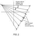
- FIG. 2shows a standard equilinear detector geometry in which the detectors are arranged with constant spacing along a line or plane;
- FIG. 3shows the radiation profile of an imaged object defined by an equilinear arrangement of detectors
- FIG. 4shows a standard equiangular detector geometry in which the detectors are arranged with constant angular spacing along an arc or cylindrical surface
- FIG. 5shows the radiation profile of an imaged object defined by an equiangular arrangement of detectors
- FIG. 6shows three equilinear-spaced detector arrays positioned and angled relative to one another, resulting in a geometry that is neither equilinear nor equiangular;
- FIG. 7shows the predicted radius of reconstructed object with three detector arrays generally positioned along an arc having a radius centered at the x-ray focal spot
- FIG. 8shows the predicted radius of reconstructed object with three 1D linear or 2D flat plate detector arrays positioned along a straight line in an equilinear arrangement
- FIG. 9is a flow chart diagram of the rebinning algorithm for reconstructing 1D fan beam or 2D cone beam projection data which is neither equilinear or equiangular;
- FIG. 10shows the projection of multiple angled detector array positions onto a single virtual flat equilinear detector array
- FIG. 11shows the projection of multiple angled detector array positions onto a single virtual curved equiangular detector array
- FIG. 12is a schematic diagram of an x-ray scanning system having a gantry positioning apparatus mounted to a cantilevered O-shaped gantry and a mobile cart.
- a radiation source 13projects radiation onto multiple one-dimensional linear or two-dimensional planar area detector arrays 14 that are angled generally along line or a circle.
- the detector arraysgenerate scan data from a plurality of diverging radiation beams, i.e., a fan beam or cone beam.
- the source and detectorsare rotated around the object to be imaged, and a plurality of projection images is captured to computer memory for tomographic projection image processing.
- a single sourceproduces a fan or cone beam which is read by a linear 1D or 2D array of detectors, as shown on the left.
- the detectorsoccupy a 1D arc to image fan beam data, or a 2D cylindriacal surface to image cone beam data.
- an equilinear detector geometryis more clearly defined.
- the detector elements in an arrayare arranged with constant spacing along a straight line or a flat plane.
- the angle between rays connecting the x-ray source point and the detector elementsdoes not remain constant.
- a radiation absorption profile, or imageis generated with varying amplitudes for a region between the bank of detectors and the x-ray source, as shown in FIG. 3 .
- FIGS. 4-5illustrate an equiangular detector geometry. As illustrated in FIG. 4 , the detector elements in an equiangular array are arranged with constant angular spacing along a circle or cylinder. In an equiangular geometry, in contrast to equilinear geometry, the angle between rays connecting the x-ray source point and the detector elements remains constant, but the distance between detectors may change.
- FIG. 5shows the radiation absorption profile for the region between the bank of detectors and the x-ray source. Each ray is identified by its angle, ⁇ , from the central ray, and the absorption profile is denoted by the function R ⁇ ( ⁇ ).
- One method for achieving a wide field-of-viewis to use multiple 1D or 2D detectors, arranged end-to-end and angled relative to one another, as shown in FIG. 6 .
- Another techniqueis to use a single array, translated to discrete positions along an arc opposite the x-ray source, to obtain a large “effective” field of view. In either case, when one or more equilinear 1D linear fan beam or 2D planar cone beam detector arrays are positioned and angled along an arc opposite the x-ray source, the resulting geometry is neither equilinear or equiangular. As illustrated in FIG.
- the projection of equally spaced detector elements, d j , on the angled arraysdo not project onto equally spaced detectors, p j , located on lines, planes, or arcs.
- the process of reprojecting these elements onto a new virtual detector array which is coincident or parallel to the central detector arraywill result in projections that are not equidistant.
- the spacing of detector arrayscannot be assumed to be equal.
- FIG. 7shows in more detail the result of filtering on non-equally spaced detectors.
- FIG. 8illustrates this same calculation of the predicted radius of the reconstructed object assuming the same input parameters of focal length and detector length, but where the detector arrays are arranged in a plane to provide equilinear geometry.
- the predicted radius of the angled detector geometryis larger than that of the equilinear detector geometry, and the resultant images with the angled detector geometry will be distorted geometrically.
- the algorithm shown in FIG. 9describes a method of reconstructing fan beam or cone beam x-ray projection data of an object, where the detector configuration is neither equilinear or equiangular.
- the algorithmdescribes a method for generating a new virtual equilinear or equiangular fan beam or cone beam detector array which is defined along a straight line or generally along an arc. For every pixel defined in the virtual detector array, the projection point in the original projection data is determined and the x-ray absorption amplitude for that point is calculated by interpolating the nearest neighbor pixels.
- standard filtered backprojection and algebraic reconstruction techniquesmay be performed to generate image data.
- the methodconsists of creating a single virtual detector array for each projection position, which is defined as being equilinear or equiangular, and reprojecting two more real detector arrays onto the virtual array. Once the real projection data is reprojected onto the virtual detector, the data is filtered and backprojected using standard tomographic reconstruction techniques;
- the projection angle index, iprojis first assigned the value 1.
- the x-ray source and detector array(s)are moved to a projection angle relative to the object being imaged. This can be accomplished by either moving the source and detector relative to a stationary object (preferably by moving the source and detector in a circle or arc around the object), or by keeping the source and detector stationary and rotating the object to the desired projection angle.
- the projection datacan obtained for a plurality of projection angles (1 . . . nproj), preferably at a plurality of equally spaced angles as the source/detector and object are rotated 360 degrees with respect to each other.
- a new virtual equilinear or equiangular array, Pis allocated.
- the virtual array, Pincludes virtual pixels which are equally spaced in distance along a line or plane in the case of a virtual equilinear array, or equally spaced in angle along an arc or curved plane in the case of a virtual equiangular array.
- the real projection data, D, from each real detector array (1 . . . ndet)is acquired for the given projection angle, iproj.
- the real projection datais then reprojected onto the virtual array, P, at step 107 .
- the reprojection subroutineincludes looping through each virtual pixel in the virtual array, P, (step 109 ), and for each virtual pixel, determining the real detector pixel, d, that is intersected by the line connecting the virtual pixel and the x-ray source (step 111 ).
- an interpolation techniquethen is applied to d and its nearest neighbors on the real detector array to compute an x-ray absorption amplitude value to be assigned to the virtual pixel, p (step 112 ). This process is repeated until absorption amplitude values have been assigned to each of the virtual pixels in the virtual array.
- step 117data from the virtual detector array is then filtered at step 117 and backprojected at step 118 .
- the filtering stepwhich can be visualized as a simple weighting of each Fourier transformed projection in the frequency domain
- the backprojection stepwhich can be seen as the dual, or in a more strict mathematical sense, the adjoint, of projection.
- a projection valueis backprojected, or smeared out, over the image points along the ray. This entire process is then repeated for each of the projection angles.
- FIGS. 10 and 11the process of reprojecting x-rays onto virtual equilinear and equiangular detector arrays is schematically illustrated.
- a new equilinear virtual detectoris allocated and defined along a one-dimensional line in the case that a fan beam geometry, or along a two-dimensional flat plane in the case of a cone beam geometry.
- the imagesare captured by the actual three-panel detector array, and then a new equiangular virtual detector is allocated.
- the equiangular virtual detectoris an arc in the case of a fan beam geometry, and a curved cylindrical surface in the case of a cone beam geometry.
- the new virtual arrayassumes that detector elements are equally spaced in distance or angle, respectively.
- the projected position in the real detector arraysis computed and an interpolation technique is applied to nearest neighbors on the real array to compute the correct x-ray absorption amplitude of the object to be reconstructed.
- an interpolation techniqueis applied to nearest neighbors on the real array to compute the correct x-ray absorption amplitude of the object to be reconstructed.
- the real detector arraycomprises three flat panel detectors arranged end-to-end, and angled to approximate an arc having a radius centered on the focal spot of the radiation source. It will be understood, however, that the principles of the invention can be used with actual detectors having any number of detector elements, including both 1D line detectors and 2D panel detectors, where the geometry of the actual detector is neither equilinear or equiangular. In addition, the principles of the present invention can be advantageously employed in a system where one or more detectors are movable to various discrete positions along a line or arc relative to the x-ray source, such as described in co-pending U.S. patent application Ser. No. 10/392,365, filed on Mar.
- FIG. 12is a schematic diagram showing an x-ray scanning system 10 described in U.S. patent application Ser. No. 10/645,322.
- the x-ray scanning system 10includes a gantry 11 secured to a support structure, which could be a mobile or stationary cart, a patient table, a wall, a floor, or a ceiling.
- the x-ray scanning system 10can be used to obtain two-dimensional planar or three-dimensional computerized tomographic (CT) x-ray images of an object, such as a patient.
- CTcomputerized tomographic
- the gantry 11is a generally circular, or “O-shaped,” housing having a central opening into which an object being imaged is placed. It will be understood that various other gantry configurations, such as a “C-shaped” gantry, can also be employed.
- the gantry 11contains an x-ray source (such as a rotating anode pulsed x-ray source) that projects a beam of x-ray radiation into the central opening of the gantry, through the object being imaged, and onto a detector array (such as a flat panel digital detector array) located on the opposite side of the gantry.
- the x-rays received at the detectorcan then be used to produce a two-dimensional or three-dimensional image of the object using well-known techniques.
- the x-ray sourceis able to rotate around the interior of the gantry 11 in a continuous or step-wise manner so that the x-ray beam can be projected through the object, and through a common isocenter, at various angles over a partial or full 360 degree rotation.
- the detector arrayis also rotated around the interior of the gantry, in coordination with the rotation of the x-ray source, so that for each projection angle of the x-ray source, the detector array is positioned opposite the x-ray source on the gantry.
- the apparatusis thus able to obtain high-quality x-ray images of the targeted object in any projection plane over a partial or full 360 degree rotation.
Landscapes
- Physics & Mathematics (AREA)
- General Physics & Mathematics (AREA)
- Engineering & Computer Science (AREA)
- Theoretical Computer Science (AREA)
- Apparatus For Radiation Diagnosis (AREA)
- Image Processing (AREA)
Abstract
Description
Claims (26)
Priority Applications (2)
| Application Number | Priority Date | Filing Date | Title |
|---|---|---|---|
| US11/514,727US7903779B2 (en) | 2002-08-21 | 2006-08-31 | Apparatus and method for reconstruction of volumetric images in a divergent scanning computed tomography system |
| US13/027,857US7965811B1 (en) | 2002-08-21 | 2011-02-15 | Apparatus and method for reconstruction of volumetric images in a divergent scanning computed tomography system |
Applications Claiming Priority (3)
| Application Number | Priority Date | Filing Date | Title |
|---|---|---|---|
| US40509602P | 2002-08-21 | 2002-08-21 | |
| US10/645,323US7106825B2 (en) | 2002-08-21 | 2003-08-21 | Apparatus and method for reconstruction of volumetric images in a divergent scanning computed tomography system |
| US11/514,727US7903779B2 (en) | 2002-08-21 | 2006-08-31 | Apparatus and method for reconstruction of volumetric images in a divergent scanning computed tomography system |
Related Parent Applications (1)
| Application Number | Title | Priority Date | Filing Date |
|---|---|---|---|
| US10/645,323ContinuationUS7106825B2 (en) | 2002-08-21 | 2003-08-21 | Apparatus and method for reconstruction of volumetric images in a divergent scanning computed tomography system |
Related Child Applications (1)
| Application Number | Title | Priority Date | Filing Date |
|---|---|---|---|
| US13/027,857ContinuationUS7965811B1 (en) | 2002-08-21 | 2011-02-15 | Apparatus and method for reconstruction of volumetric images in a divergent scanning computed tomography system |
Publications (2)
| Publication Number | Publication Date |
|---|---|
| US20070104308A1 US20070104308A1 (en) | 2007-05-10 |
| US7903779B2true US7903779B2 (en) | 2011-03-08 |
Family
ID=31946812
Family Applications (3)
| Application Number | Title | Priority Date | Filing Date |
|---|---|---|---|
| US10/645,323Expired - LifetimeUS7106825B2 (en) | 2002-08-21 | 2003-08-21 | Apparatus and method for reconstruction of volumetric images in a divergent scanning computed tomography system |
| US11/514,727Expired - LifetimeUS7903779B2 (en) | 2002-08-21 | 2006-08-31 | Apparatus and method for reconstruction of volumetric images in a divergent scanning computed tomography system |
| US13/027,857Expired - LifetimeUS7965811B1 (en) | 2002-08-21 | 2011-02-15 | Apparatus and method for reconstruction of volumetric images in a divergent scanning computed tomography system |
Family Applications Before (1)
| Application Number | Title | Priority Date | Filing Date |
|---|---|---|---|
| US10/645,323Expired - LifetimeUS7106825B2 (en) | 2002-08-21 | 2003-08-21 | Apparatus and method for reconstruction of volumetric images in a divergent scanning computed tomography system |
Family Applications After (1)
| Application Number | Title | Priority Date | Filing Date |
|---|---|---|---|
| US13/027,857Expired - LifetimeUS7965811B1 (en) | 2002-08-21 | 2011-02-15 | Apparatus and method for reconstruction of volumetric images in a divergent scanning computed tomography system |
Country Status (3)
| Country | Link |
|---|---|
| US (3) | US7106825B2 (en) |
| AU (1) | AU2003262726A1 (en) |
| WO (1) | WO2004019279A2 (en) |
Cited By (4)
| Publication number | Priority date | Publication date | Assignee | Title |
|---|---|---|---|---|
| US20110276179A1 (en)* | 2008-10-14 | 2011-11-10 | University Of Florida Research Foundation, Inc. | Imaging platform to provide integrated navigation capabilities for surgical guidance |
| US9724058B2 (en) | 2002-03-19 | 2017-08-08 | Medtronic Navigation, Inc. | Systems and methods for imaging large field-of-view objects |
| US11350995B2 (en) | 2016-10-05 | 2022-06-07 | Nuvasive, Inc. | Surgical navigation systems and methods |
| US11375962B2 (en)* | 2019-08-05 | 2022-07-05 | Linev Systems, Inc. | Fast foreign object scanner for scanning human bodies |
Families Citing this family (173)
| Publication number | Priority date | Publication date | Assignee | Title |
|---|---|---|---|---|
| US7188998B2 (en) | 2002-03-13 | 2007-03-13 | Breakaway Imaging, Llc | Systems and methods for quasi-simultaneous multi-planar x-ray imaging |
| AU2003245439A1 (en) | 2002-06-11 | 2003-12-22 | Breakaway Imaging, Llc | Cantilevered gantry apparatus for x-ray imaging |
| US7106825B2 (en)* | 2002-08-21 | 2006-09-12 | Breakaway Imaging, Llc | Apparatus and method for reconstruction of volumetric images in a divergent scanning computed tomography system |
| ATE471110T1 (en)* | 2002-08-21 | 2010-07-15 | Breakaway Imaging Llc | SCAFFOLD POSITIONING DEVICE FOR X-RAY EQUIPMENT |
| US8804899B2 (en) | 2003-04-25 | 2014-08-12 | Rapiscan Systems, Inc. | Imaging, data acquisition, data transmission, and data distribution methods and systems for high data rate tomographic X-ray scanners |
| US8204173B2 (en)* | 2003-04-25 | 2012-06-19 | Rapiscan Systems, Inc. | System and method for image reconstruction by using multi-sheet surface rebinning |
| CA2527078A1 (en)* | 2003-05-27 | 2004-12-09 | Clean Earth Technologies, Llc | Method for fast image reconstruction with compact radiation source and detector arrangement using computerized tomography |
| DE102005044653A1 (en)* | 2005-09-19 | 2007-03-29 | Siemens Ag | Method and device for reconstructing a three-dimensional image volume from two-dimensional projection images |
| US7187750B1 (en)* | 2005-09-20 | 2007-03-06 | General Electric Company | Method and apparatus for compensating non-uniform detector collimator plates |
| CN100565336C (en)* | 2005-11-21 | 2009-12-02 | 清华大学 | imaging system |
| US7929747B2 (en)* | 2006-04-25 | 2011-04-19 | Wisconsin Alumni Research Foundation | System and method for estimating data missing from CT imaging projections |
| JP4894359B2 (en)* | 2006-06-05 | 2012-03-14 | ソニー株式会社 | X-ray tomographic imaging apparatus and X-ray tomographic imaging method |
| DE102006041033B4 (en)* | 2006-09-01 | 2017-01-19 | Siemens Healthcare Gmbh | Method for reconstructing a three-dimensional image volume |
| US20080140180A1 (en)* | 2006-12-07 | 2008-06-12 | Medtronic Vascular, Inc. | Vascular Position Locating Apparatus and Method |
| US20080147173A1 (en)* | 2006-12-18 | 2008-06-19 | Medtronic Vascular, Inc. | Prosthesis Deployment Apparatus and Methods |
| US8473030B2 (en) | 2007-01-12 | 2013-06-25 | Medtronic Vascular, Inc. | Vessel position and configuration imaging apparatus and methods |
| US20080172119A1 (en)* | 2007-01-12 | 2008-07-17 | Medtronic Vascular, Inc. | Prosthesis Deployment Apparatus and Methods |
| US7434996B2 (en)* | 2007-01-19 | 2008-10-14 | General Electric Co. | Method and apparatus for a C-arm system |
| US20080188921A1 (en)* | 2007-02-02 | 2008-08-07 | Medtronic Vascular, Inc. | Prosthesis Deployment Apparatus and Methods |
| DE102007026115B4 (en)* | 2007-06-05 | 2017-10-12 | Siemens Healthcare Gmbh | Method for generating a 3D reconstruction of a body |
| US20090008564A1 (en)* | 2007-07-05 | 2009-01-08 | Cmt Medical Technologies Ltd. | Modular X-Ray Detector With Single Photon Counting, Energy Sensitivity And Integration Capabilities |
| US20090259284A1 (en)* | 2008-04-10 | 2009-10-15 | Medtronic Vascular, Inc. | Resonating Stent or Stent Element |
| US20090259296A1 (en)* | 2008-04-10 | 2009-10-15 | Medtronic Vascular, Inc. | Gate Cannulation Apparatus and Methods |
| EP2389114A1 (en) | 2009-01-21 | 2011-11-30 | Koninklijke Philips Electronics N.V. | Method and apparatus for large field of view imaging and detection and compensation of motion artifacts |
| US9737235B2 (en)* | 2009-03-09 | 2017-08-22 | Medtronic Navigation, Inc. | System and method for image-guided navigation |
| US9226689B2 (en) | 2009-03-10 | 2016-01-05 | Medtronic Xomed, Inc. | Flexible circuit sheet |
| US8504139B2 (en) | 2009-03-10 | 2013-08-06 | Medtronic Xomed, Inc. | Navigating a surgical instrument |
| US9226688B2 (en) | 2009-03-10 | 2016-01-05 | Medtronic Xomed, Inc. | Flexible circuit assemblies |
| US8737708B2 (en) | 2009-05-13 | 2014-05-27 | Medtronic Navigation, Inc. | System and method for automatic registration between an image and a subject |
| US8503745B2 (en)* | 2009-05-13 | 2013-08-06 | Medtronic Navigation, Inc. | System and method for automatic registration between an image and a subject |
| US8238631B2 (en) | 2009-05-13 | 2012-08-07 | Medtronic Navigation, Inc. | System and method for automatic registration between an image and a subject |
| DE112009005019B4 (en) | 2009-06-30 | 2022-02-03 | Analogic Corp. | Efficient quasi-exact 3D image reconstruction algorithm for CT scanners |
| US20110110570A1 (en)* | 2009-11-10 | 2011-05-12 | Avi Bar-Shalev | Apparatus and methods for generating a planar image |
| KR101478264B1 (en) | 2010-04-30 | 2014-12-31 | 메드트로닉 좀드 인코퍼레이티드 | Navigated malleable surgical instrument |
| US8842893B2 (en) | 2010-04-30 | 2014-09-23 | Medtronic Navigation, Inc. | Method and apparatus for image-based navigation |
| US8737567B2 (en) | 2011-01-27 | 2014-05-27 | Medtronic Navigation, Inc. | Image acquisition optimization |
| US10492868B2 (en) | 2011-01-28 | 2019-12-03 | Medtronic Navigation, Inc. | Method and apparatus for image-based navigation |
| US9974501B2 (en) | 2011-01-28 | 2018-05-22 | Medtronic Navigation, Inc. | Method and apparatus for image-based navigation |
| US10617374B2 (en) | 2011-01-28 | 2020-04-14 | Medtronic Navigation, Inc. | Method and apparatus for image-based navigation |
| US8768019B2 (en) | 2011-02-03 | 2014-07-01 | Medtronic, Inc. | Display of an acquired cine loop for procedure navigation |
| US8562211B2 (en) | 2011-03-30 | 2013-10-22 | Medtronic Navigation, Inc. | System and method for off-center imaging |
| US9411057B2 (en) | 2011-04-01 | 2016-08-09 | Medtronic Navigation, Inc. | X-ray imaging system and method |
| US8811662B2 (en) | 2011-04-29 | 2014-08-19 | Medtronic Navigation, Inc. | Method and apparatus for calibrating and re-aligning an ultrasound image plane to a navigation tracker |
| US9138204B2 (en) | 2011-04-29 | 2015-09-22 | Medtronic Navigation, Inc. | Method and apparatus for calibrating and re-aligning an ultrasound image plane to a navigation tracker |
| US8971495B2 (en) | 2011-06-02 | 2015-03-03 | Medtronic Navigation, Inc. | Method and apparatus for power control in an image-based navigation system |
| US8767910B2 (en) | 2011-06-22 | 2014-07-01 | Medtronic Navigation, Inc. | Hybrid multi-row detector and flat panel imaging system |
| US10849574B2 (en) | 2011-06-22 | 2020-12-01 | Medtronic Navigation, Inc. | Interventional imaging |
| US9008414B2 (en) | 2011-10-04 | 2015-04-14 | Medtronic Navigation, Inc. | Method and apparatus for assisted trajectory planning |
| US9750486B2 (en) | 2011-10-25 | 2017-09-05 | Medtronic Navigation, Inc. | Trackable biopsy needle |
| US8948338B2 (en) | 2011-11-03 | 2015-02-03 | Medtronic Navigation, Inc. | Dynamically scanned X-ray detector panel |
| US9168008B2 (en)* | 2011-11-03 | 2015-10-27 | General Electric Company | Coarse segmented detector architecture and method of making same |
| KR101945720B1 (en)* | 2012-01-10 | 2019-02-08 | 삼성전자주식회사 | Apparatus and Method for virtual view generation on multi-view image reconstruction system |
| US8891847B2 (en) | 2012-01-23 | 2014-11-18 | Medtronic Navigation, Inc. | Automatic implant detection from image artifacts |
| CN103308535B (en)* | 2012-03-09 | 2016-04-13 | 同方威视技术股份有限公司 | For equipment and the method for ray scanning imaging |
| EP2676627B1 (en) | 2012-04-18 | 2021-07-28 | Medtronic Navigation, Inc. | System and method for automatic registration between an image and a subject |
| US9498290B2 (en) | 2012-07-19 | 2016-11-22 | MRI Interventions, Inc. | Surgical navigation devices and methods |
| CN103674979B (en)* | 2012-09-19 | 2016-12-21 | 同方威视技术股份有限公司 | A kind of luggage and articles CT safe examination system and detector assembly thereof |
| US9089266B2 (en)* | 2013-04-19 | 2015-07-28 | Kabushiki Kaisha Toshiba | Tilted detector array for medical imaging systems including computed tomography |
| US10278729B2 (en) | 2013-04-26 | 2019-05-07 | Medtronic Xomed, Inc. | Medical device and its construction |
| WO2014204628A1 (en)* | 2013-06-17 | 2014-12-24 | Hexagon Metrology, Inc. | Method and apparatus of measuring objects using selective imaging |
| TWI517093B (en) | 2013-10-11 | 2016-01-11 | Univ Nat Yang Ming | Computer tomography reconstruction method |
| US9974525B2 (en) | 2014-10-31 | 2018-05-22 | Covidien Lp | Computed tomography enhanced fluoroscopic system, device, and method of utilizing the same |
| US10010296B2 (en)* | 2014-12-30 | 2018-07-03 | Morpho Detection, Llc | Systems and methods for x-ray CT scanner with reconfigurable field of view |
| DE102015213911B4 (en)* | 2015-07-23 | 2019-03-07 | Siemens Healthcare Gmbh | Method for generating an X-ray image and data processing device for carrying out the method |
| US10702226B2 (en) | 2015-08-06 | 2020-07-07 | Covidien Lp | System and method for local three dimensional volume reconstruction using a standard fluoroscope |
| US10716525B2 (en) | 2015-08-06 | 2020-07-21 | Covidien Lp | System and method for navigating to target and performing procedure on target utilizing fluoroscopic-based local three dimensional volume reconstruction |
| US10674982B2 (en) | 2015-08-06 | 2020-06-09 | Covidien Lp | System and method for local three dimensional volume reconstruction using a standard fluoroscope |
| JP6370280B2 (en)* | 2015-09-16 | 2018-08-08 | 富士フイルム株式会社 | Tomographic image generating apparatus, method and program |
| US11172895B2 (en) | 2015-12-07 | 2021-11-16 | Covidien Lp | Visualization, navigation, and planning with electromagnetic navigation bronchoscopy and cone beam computed tomography integrated |
| USD824027S1 (en) | 2016-01-13 | 2018-07-24 | MRI Interventions, Inc. | Fins for a support column for a surgical trajectory frame |
| USD829904S1 (en) | 2016-01-13 | 2018-10-02 | MRI Interventions, Inc. | Curved bracket for surgical navigation systems |
| US10376333B2 (en) | 2016-01-14 | 2019-08-13 | MRI Interventions, Inc. | Devices for surgical navigation systems |
| CN107280700B (en)* | 2016-03-31 | 2023-06-20 | 通用电气公司 | CT imaging equipment and method, X-ray receiving and transmitting assembly for CT imaging equipment |
| US11172821B2 (en) | 2016-04-28 | 2021-11-16 | Medtronic Navigation, Inc. | Navigation and local thermometry |
| US10191615B2 (en) | 2016-04-28 | 2019-01-29 | Medtronic Navigation, Inc. | Method and apparatus for image-based navigation |
| US10709508B2 (en) | 2016-07-28 | 2020-07-14 | Medtronics Ps Medical, Inc. | Tracked powered drill assembly |
| US11839433B2 (en) | 2016-09-22 | 2023-12-12 | Medtronic Navigation, Inc. | System for guided procedures |
| US11051886B2 (en) | 2016-09-27 | 2021-07-06 | Covidien Lp | Systems and methods for performing a surgical navigation procedure |
| US10667923B2 (en) | 2016-10-31 | 2020-06-02 | Warsaw Orthopedic, Inc. | Sacro-iliac joint implant system and method |
| US11842030B2 (en) | 2017-01-31 | 2023-12-12 | Medtronic Navigation, Inc. | Method and apparatus for image-based navigation |
| US10699448B2 (en) | 2017-06-29 | 2020-06-30 | Covidien Lp | System and method for identifying, marking and navigating to a target using real time two dimensional fluoroscopic data |
| US10463404B2 (en) | 2017-07-27 | 2019-11-05 | Warsaw Orthopedic, Inc. | Spinal implant system and method |
| US11399784B2 (en) | 2017-09-29 | 2022-08-02 | Medtronic Navigation, Inc. | System and method for mobile imaging |
| EP3694412A4 (en) | 2017-10-10 | 2021-08-18 | Covidien LP | SYSTEM AND METHOD FOR IDENTIFYING AND MARKING A TARGET IN A FLUOROSCOPIC THREE-DIMENSIONAL RECONSTRUCTION |
| US20190175059A1 (en) | 2017-12-07 | 2019-06-13 | Medtronic Xomed, Inc. | System and Method for Assisting Visualization During a Procedure |
| US10905498B2 (en) | 2018-02-08 | 2021-02-02 | Covidien Lp | System and method for catheter detection in fluoroscopic images and updating displayed position of catheter |
| US11138768B2 (en) | 2018-04-06 | 2021-10-05 | Medtronic Navigation, Inc. | System and method for artifact reduction in an image |
| CN108652656B (en)* | 2018-05-21 | 2024-04-12 | 北京达影科技有限公司 | Composite detector, tomographic imaging system and method |
| US11977037B2 (en) | 2018-10-22 | 2024-05-07 | Rapiscan Holdings, Inc. | Insert for screening tray |
| US11918297B2 (en) | 2019-01-10 | 2024-03-05 | Mazor Robotics Ltd. | System and method for registration between coordinate systems and navigation |
| US11135025B2 (en) | 2019-01-10 | 2021-10-05 | Medtronic Navigation, Inc. | System and method for registration between coordinate systems and navigation |
| US11426242B2 (en) | 2019-01-30 | 2022-08-30 | Medtronic Navigation, Inc. | System and method for registration between coordinate systems and navigation of selected members |
| US11911110B2 (en) | 2019-01-30 | 2024-02-27 | Medtronic Navigation, Inc. | System and method for registration between coordinate systems and navigation of selected members |
| US11065065B2 (en) | 2019-02-22 | 2021-07-20 | Warsaw Orthopedic, Inc. | Spinal implant system and methods of use |
| US11285022B2 (en) | 2019-04-15 | 2022-03-29 | Warsaw Orthopedic, Inc. | Spinal implant system and method |
| US11547491B2 (en) | 2019-05-02 | 2023-01-10 | Medtronic Navigation, Inc. | Oral patient tracking device and method of using the same |
| US11446094B2 (en) | 2019-05-02 | 2022-09-20 | Medtronic Navigation, Inc. | Nasal patient tracking device and method of using the same |
| US11672607B2 (en) | 2019-08-14 | 2023-06-13 | Warsaw Orthopedic, Inc. | Systems, devices, and methods for surgical navigation with anatomical tracking |
| US11399965B2 (en) | 2019-09-09 | 2022-08-02 | Warsaw Orthopedic, Inc. | Spinal implant system and methods of use |
| US11564812B2 (en) | 2019-09-09 | 2023-01-31 | Warsaw Orthopedic, Inc. | Surgical instrument and method |
| WO2021051191A1 (en) | 2019-09-16 | 2021-03-25 | Voti Inc. | Probabilistic image analysis |
| US11576685B2 (en) | 2019-10-25 | 2023-02-14 | Medtronic Ps Medical, Inc. | Drill guide assembly and method |
| US11890205B2 (en) | 2019-12-13 | 2024-02-06 | Warsaw Orthopedic, Inc. | Spinal implant system and methods of use |
| US11666755B2 (en) | 2020-01-24 | 2023-06-06 | Medtronic Xomed, Inc. | System and method for therapy |
| US11167140B2 (en) | 2020-01-24 | 2021-11-09 | Medtronic Xomed, Inc. | System and method for therapy |
| US11167127B2 (en) | 2020-01-24 | 2021-11-09 | Medtronic Xomed, Inc. | System and method for therapy |
| US11623086B2 (en) | 2020-01-24 | 2023-04-11 | Medtronic Xomed, Inc. | System and method for therapy |
| US11730546B2 (en) | 2020-01-24 | 2023-08-22 | Warsaw Orthopedic, Inc. | Spinal implant system and method |
| EP4125600A4 (en) | 2020-04-20 | 2023-08-23 | Shanghai United Imaging Healthcare Co., Ltd. | Imaging systems and methods |
| CN111991015B (en)* | 2020-08-13 | 2024-04-26 | 上海联影医疗科技股份有限公司 | Three-dimensional image stitching method, device, equipment, system and storage medium |
| US11857267B2 (en) | 2020-04-22 | 2024-01-02 | Medtronic Navigation, Inc. | System and method for navigation |
| US20210330390A1 (en) | 2020-04-22 | 2021-10-28 | Medtronic Navigation, Inc. | System and method for navigation |
| US11571261B2 (en) | 2020-04-22 | 2023-02-07 | Medtronic Navigation, Inc. | System and method for navigation |
| US20210346093A1 (en) | 2020-05-06 | 2021-11-11 | Warsaw Orthopedic, Inc. | Spinal surgery system and methods of use |
| US11364130B2 (en) | 2020-09-01 | 2022-06-21 | Warsaw Orthopedic, Inc. | Spinal implant system and method |
| EP4210581B1 (en) | 2020-09-14 | 2025-07-02 | Medtronic Navigation, Inc. | System and method for imaging |
| US12076172B2 (en) | 2020-09-14 | 2024-09-03 | Medtronic Navigation, Inc. | System and method for imaging |
| US11813094B2 (en) | 2020-09-14 | 2023-11-14 | Medtronic Navigation, Inc. | System and method for imaging |
| US12023187B2 (en) | 2020-09-14 | 2024-07-02 | Medtronic Navigation, Inc. | System and method for imaging |
| US11801149B2 (en) | 2020-10-09 | 2023-10-31 | Warsaw Orthopedic, Inc. | Surgical instrument and method |
| EP4267029A1 (en) | 2020-12-23 | 2023-11-01 | Medtronic Navigation, Inc. | Powered drill assembly |
| US12245772B2 (en) | 2020-12-23 | 2025-03-11 | Medtronic Navigation, Inc. | System and method to control operation of a drill |
| US12239327B2 (en) | 2020-12-23 | 2025-03-04 | Medtronic Navigation, Inc. | Powered drill assembly |
| US11769261B2 (en) | 2021-03-18 | 2023-09-26 | Medtronic Navigation, Inc. | Imaging system |
| US11922645B2 (en) | 2021-03-18 | 2024-03-05 | Medtronic Navigation, Inc. | Imaging system |
| US20220313340A1 (en) | 2021-04-06 | 2022-10-06 | Medtronic Navigation, Inc. | Energizable instrument assembly |
| US20220313374A1 (en) | 2021-04-06 | 2022-10-06 | Medtronic Navigation, Inc. | Powered Drill Assembly |
| US11885752B2 (en) | 2021-06-30 | 2024-01-30 | Rapiscan Holdings, Inc. | Calibration method and device therefor |
| US12019035B2 (en) | 2021-07-16 | 2024-06-25 | Rapiscan Holdings, Inc. | Material detection in x-ray security screening |
| US11742959B2 (en) | 2021-08-25 | 2023-08-29 | Medtronic, Inc. | System and method for wireless communications |
| US12097060B2 (en) | 2022-02-01 | 2024-09-24 | Medtronic Navigation, Inc. | Long axis imaging system and method |
| US20240071025A1 (en) | 2022-08-31 | 2024-02-29 | Mazor Robotics Ltd. | System and method for imaging |
| US20240065661A1 (en) | 2022-08-31 | 2024-02-29 | Mazor Robotics Ltd. | System and method for imaging |
| US12257092B2 (en) | 2022-10-17 | 2025-03-25 | Medtronic Navigation, Inc. | Method to superimpose rendering over spine hardware implants on images produced by Cbct scanner system |
| US20240138914A1 (en) | 2022-10-27 | 2024-05-02 | Medtronic Navigation, Inc. | Method and apparatus for planning placement of an implant |
| US20240138915A1 (en) | 2022-10-27 | 2024-05-02 | Medtronic Navigation, Inc. | Method And Apparatus For Planning Placement Of An Implant |
| WO2024089502A1 (en) | 2022-10-28 | 2024-05-02 | Medtronic, Inc. | System and method for illustrating a pose of an object |
| WO2024089503A1 (en) | 2022-10-28 | 2024-05-02 | Medtronic, Inc. | System and method for illustrating a pose of an object |
| WO2024089504A1 (en) | 2022-10-28 | 2024-05-02 | Medtronic, Inc. | System operable to determine a pose of an instrument |
| US20240197404A1 (en) | 2022-12-15 | 2024-06-20 | Medtronic Navigation, Inc. | Method and Apparatus for Imaging a Subject |
| US20240277415A1 (en) | 2023-02-21 | 2024-08-22 | Mazor Robotics Ltd. | System and method for moving a guide system |
| US20240285348A1 (en) | 2023-02-28 | 2024-08-29 | Mazor Robotics Ltd. | Automated movement of optical localizer for optimal line of sight with optical trackers |
| US20240307131A1 (en) | 2023-03-15 | 2024-09-19 | Mazor Robotics Ltd. | Systems And Methods For An Image Guided Procedure |
| US20240328784A1 (en) | 2023-03-28 | 2024-10-03 | Medtronic Navigation, Inc. | Tracking device and method of using the same |
| US12413843B2 (en) | 2023-04-07 | 2025-09-09 | Medtronic Navigation, Inc. | System and method of patient registration |
| WO2024214033A1 (en) | 2023-04-13 | 2024-10-17 | Medtronic Navigation, Inc. | Ultrasound depth calibration for improving navigational accuracy |
| WO2024215790A1 (en) | 2023-04-13 | 2024-10-17 | Medtronic, Inc. | System and method for positioning a member relative to a subject |
| WO2024215791A1 (en) | 2023-04-13 | 2024-10-17 | Medtronic, Inc. | System and method for positioning a member relative to a subject |
| WO2024214057A1 (en) | 2023-04-13 | 2024-10-17 | Medtronic Navigation, Inc. | System and method for illustrating a pose of an object |
| WO2024215866A1 (en) | 2023-04-14 | 2024-10-17 | Medtronic Navigation, Inc. | System and method for imaging and registration for navigation |
| WO2024224319A1 (en) | 2023-04-25 | 2024-10-31 | Medtronic Navigation, Inc. | Systems and methods for imaging wide film radiographs |
| WO2024224310A1 (en) | 2023-04-26 | 2024-10-31 | Medtronic Navigation, Inc. | Surgical cart with robotic arm |
| WO2024224351A2 (en) | 2023-04-27 | 2024-10-31 | Medtronic Navigation, Inc. | System and method for reducing tool vibration at a variable stiffness end effector of a surgical system |
| WO2024224350A1 (en) | 2023-04-27 | 2024-10-31 | Medtronic Navigation, Inc. | System for reducing tool vibration at a variable stiffness end effector of a surgical system |
| WO2024238179A1 (en) | 2023-05-15 | 2024-11-21 | Medtronic Navigation, Inc. | Long image multi-field of view preview |
| WO2024254040A1 (en) | 2023-06-09 | 2024-12-12 | Medtronic Navigation, Inc. | Touch and move anatomy localization |
| WO2024257036A1 (en) | 2023-06-16 | 2024-12-19 | Medtronic Navigation, Inc. | System and method for navigation |
| WO2025022368A1 (en) | 2023-07-27 | 2025-01-30 | Medtronic Navigation, Inc. | System and method for navigation |
| WO2025027505A1 (en) | 2023-07-28 | 2025-02-06 | Medtronic Navigation, Inc. | System and method of patient registration |
| WO2025037234A1 (en) | 2023-08-15 | 2025-02-20 | Medtronic Navigation, Inc. | System and method for mobile imaging |
| WO2025046576A1 (en) | 2023-08-31 | 2025-03-06 | Mazor Robotics Ltd. | System and method for navigation |
| WO2025088433A1 (en) | 2023-10-26 | 2025-05-01 | Medtronic Navigation, Inc. | System and method for navigation |
| WO2025088617A1 (en) | 2023-10-27 | 2025-05-01 | Mazor Robotics Ltd. | Path planning with collision avoidance |
| WO2025088616A1 (en) | 2023-10-27 | 2025-05-01 | Mazor Robotics Ltd. | Method and apparatus for procedure navigation |
| WO2025088551A1 (en) | 2023-10-27 | 2025-05-01 | Medtronic Navigation, Inc. | System and method for navigation |
| WO2025088575A1 (en) | 2023-10-27 | 2025-05-01 | Medtronic Navigation, Inc. | System and method for navigation |
| WO2025114870A1 (en) | 2023-11-30 | 2025-06-05 | Medtronic Navigation, Inc. | System for navigation |
| WO2025158388A1 (en) | 2024-01-25 | 2025-07-31 | Medtronic Navigation, Inc. | System and method for determining a status of a tracking device |
| WO2025158394A1 (en) | 2024-01-26 | 2025-07-31 | Medtronic Navigation, Inc. | System and method for imaging |
| WO2025158335A1 (en) | 2024-01-26 | 2025-07-31 | Medtronic Navigation, Inc. | Configurable reference frame device and method of using the same |
| WO2025191487A1 (en) | 2024-03-12 | 2025-09-18 | Medtronic Navigation, Inc. | System for tracking of an instrument |
| WO2025196750A1 (en) | 2024-03-18 | 2025-09-25 | Mazor Robotics Ltd. | System and method to image data |
| WO2025203020A1 (en) | 2024-03-26 | 2025-10-02 | Mazor Robotics Ltd. | System and method to generate image visualization |
Citations (122)
| Publication number | Priority date | Publication date | Assignee | Title |
|---|---|---|---|---|
| US2818510A (en) | 1953-07-23 | 1957-12-31 | Philips Corp | Diagnostic x-ray device |
| US3549885A (en) | 1967-07-10 | 1970-12-22 | Saab Ab | Apparatus for x-raying on two mutually perpendicular axes with a pair of x-ray sources |
| US3617749A (en) | 1970-01-12 | 1971-11-02 | Philips Corp | Column support for x-ray apparatus |
| FR2304321B1 (en) | 1975-03-20 | 1979-08-31 | Emi Ltd | |
| US4200799A (en) | 1976-07-15 | 1980-04-29 | Tokyo Shibaura Electric Co., Ltd. | Tomographing device |
| GB2088670A (en) | 1980-11-26 | 1982-06-09 | Philips Nv | Radiation absorption distribution measurement in a part section of a body |
| US4352986A (en) | 1979-08-08 | 1982-10-05 | Siemens Aktiengesellschaft | Tomographic apparatus for the production of transverse layer images |
| US4442489A (en) | 1979-06-16 | 1984-04-10 | U.S. Philips Corporation | Device for computed tomography |
| US4481656A (en) | 1981-05-11 | 1984-11-06 | U.S. Philips Corporation | Medical apparatus |
| US4636952A (en)* | 1984-12-03 | 1987-01-13 | General Electric Company | Method and apparatus for back projection image reconstruction using virtual equi-spaced detector array |
| US4741015A (en) | 1986-12-05 | 1988-04-26 | B. C. Medical Compagnie Limitee | Universal X-ray unit |
| US4803714A (en) | 1983-09-13 | 1989-02-07 | B. V. Optische Industrie "De Oude Delft" | Method for forming a radiogram using slit-scanning radiographic techniques |
| US4810881A (en) | 1986-04-30 | 1989-03-07 | Thomson-Csf | Panel for X-ray photography and method of manufacture |
| US4817121A (en)* | 1986-09-24 | 1989-03-28 | Hitachi Medical Corp. | Apparatus for checking baggage with x-rays |
| US4829252A (en) | 1987-10-28 | 1989-05-09 | The Regents Of The University Of California | MRI system with open access to patient image volume |
| US4853946A (en) | 1986-11-14 | 1989-08-01 | Picker International, Inc. | Diagonostic service system for CT scanners |
| US4875228A (en) | 1988-07-12 | 1989-10-17 | Davru Manufacturing Ltd. | X-ray gantry |
| US4884293A (en) | 1988-01-19 | 1989-11-28 | Kabushiki Kaisha Toshiba | X-ray photographing apparatus |
| US4935949A (en) | 1986-01-31 | 1990-06-19 | Yokogawa Medical Systems, Limited | Gantry for computerized tomography |
| US4955046A (en) | 1989-04-17 | 1990-09-04 | Siczek Aldona A | C-arm for X-ray diagnostic examination |
| JPH02228946A (en) | 1989-03-02 | 1990-09-11 | Toshiba Corp | X-ray CT scanner device |
| US4977585A (en) | 1989-04-05 | 1990-12-11 | Imatron, Inc. | Self shielded computerized tomographic scanner |
| US4982415A (en) | 1988-06-03 | 1991-01-01 | Kabushiki Kaisha Toshiba | X-ray CT scanner apparatus |
| US4987585A (en) | 1989-04-04 | 1991-01-22 | General Electric Company | X-ray positioner for multi-axis profiling |
| US5014293A (en)* | 1989-10-04 | 1991-05-07 | Imatron, Inc. | Computerized tomographic x-ray scanner system and gantry assembly |
| US5014292A (en) | 1990-01-29 | 1991-05-07 | Siczek Bernard W | Tiltable x-ray table integrated with carriage for x-ray source and receptor |
| US5032990A (en) | 1989-05-30 | 1991-07-16 | General Electric Company | Translate rotate scanning method for x-ray imaging |
| USD323386S (en) | 1988-01-19 | 1992-01-21 | Adac Laboratories | Gantry for a medical camera |
| US5084908A (en) | 1990-02-07 | 1992-01-28 | Incubation Industries | Tomographic system |
| EP0471455A2 (en) | 1990-08-14 | 1992-02-19 | Picker International, Inc. | Imaging apparatus and methods |
| US5095501A (en) | 1989-12-06 | 1992-03-10 | Kabushiki Kaisha Toshiba | X-ray image-pickup apparatus |
| US5097497A (en) | 1991-03-01 | 1992-03-17 | Picker International, Inc. | Deployable CT medical system |
| EP0231969B1 (en) | 1986-01-31 | 1992-08-19 | Koninklijke Philips Electronics N.V. | Mobile x-ray diagnostic apparatus |
| US5159622A (en) | 1989-11-17 | 1992-10-27 | Kabushiki Kaisha Toshiba | X-ray fluoroscopic imaging apparatus with extended imaging set up range |
| US5164973A (en)* | 1990-01-05 | 1992-11-17 | Hitachi Medical Corporation | Projection detecting apparatus for computer tomography |
| US5187659A (en) | 1990-09-04 | 1993-02-16 | General Electric Company | Cone beam scanning trajectories for three-dimensional computerized tomography data acquisition where object is larger than the field of view |
| EP0564292A2 (en) | 1992-04-03 | 1993-10-06 | Picker International, Inc. | Ring tube CT scanner |
| US5265610A (en) | 1991-09-03 | 1993-11-30 | General Electric Company | Multi-planar X-ray fluoroscopy system using radiofrequency fields |
| US5287274A (en) | 1989-03-20 | 1994-02-15 | General Electric Cgr Sa | Method for acquisition of radiological data in multiple orthogonal orientations using a 2D detector relating to a body irradiated with x-rays and for reconstruction of structures corresponding to said body using an algebraic algorithm |
| USD345606S (en) | 1990-11-21 | 1994-03-29 | Picker International, Inc. | Medical gamma camera gantry |
| US5319693A (en) | 1992-12-30 | 1994-06-07 | General Electric Company | Three dimensional computerized tomography scanning configuration for imaging large objects with smaller area detectors |
| US5390112A (en) | 1993-10-04 | 1995-02-14 | General Electric Company | Three-dimensional computerized tomography scanning method and system for imaging large objects with smaller area detectors |
| JPH0767866A (en) | 1993-09-06 | 1995-03-14 | Toshiba Corp | X-ray diagnostic device |
| US5448608A (en) | 1994-02-08 | 1995-09-05 | Analogic Corporation | Tomographic scanner having center of rotation for all physics |
| US5448607A (en) | 1994-02-08 | 1995-09-05 | Analogic Corporation | X-ray tomography system with gantry pivot and translation control |
| US5452337A (en) | 1992-04-01 | 1995-09-19 | Sony Corporation | Radiation diagnostic system |
| US5499415A (en) | 1994-02-08 | 1996-03-19 | Analogic Corporation | Stabilized, cantilevered, patient trauma table system |
| US5515416A (en) | 1995-05-30 | 1996-05-07 | Siczek; Bernard W. | Bi-plane imaging device |
| US5583909A (en) | 1994-12-20 | 1996-12-10 | Oec Medical Systems, Inc. | C-arm mounting structure for mobile X-ray imaging system |
| US5592523A (en) | 1994-12-06 | 1997-01-07 | Picker International, Inc. | Two dimensional detector array for CT scanners |
| US5598453A (en) | 1994-08-30 | 1997-01-28 | Hitachi Medical Corporation | Method for X-ray fluoroscopy or radiography, and X-ray apparatus |
| DE19535583A1 (en) | 1995-09-25 | 1997-03-27 | Siemens Ag | X=ray diagnostic appts. with positioning aid |
| US5625660A (en) | 1995-06-30 | 1997-04-29 | Picker International, Inc. | Image reconstruction from helical partial cone-beam data |
| US5625662A (en) | 1995-11-20 | 1997-04-29 | General Electric Company | Modulating x-ray tube current in a CT system |
| US5638419A (en) | 1995-02-16 | 1997-06-10 | Siemens Aktiengesellschaft | Spiral-helical scan computed tomography apparatus |
| US5661772A (en) | 1996-04-01 | 1997-08-26 | Siemens Aktiengesellschaft | X-ray diagnostics apparatus capable of producing CT images and fluoroscopic images |
| US5668846A (en)* | 1996-10-18 | 1997-09-16 | General Electric Company | Methods and apparatus for scanning an object and displaying an image in a computed tomography system |
| EP0810005A2 (en) | 1993-06-09 | 1997-12-03 | Wisconsin Alumni Research Foundation | Radiation therapy system |
| US5740224A (en)* | 1994-09-27 | 1998-04-14 | University Of Delaware | Cone beam synthetic arrays in three-dimensional computerized tomography |
| US5740222A (en) | 1993-11-26 | 1998-04-14 | Kabushiki Kaisha Toshiba | Radiation computed tomography apparatus |
| US5745545A (en) | 1996-08-16 | 1998-04-28 | Siemens Medical Systems, Inc. | Alignment system and method for intra-operative radiation therapy |
| US5784428A (en) | 1996-07-24 | 1998-07-21 | Siemens Aktiengesellschaft | X-ray computed tomography apparatus having a gantry frame with rollers for axially and radially guiding the gantry |
| US5802138A (en) | 1996-02-29 | 1998-09-01 | Commissariat A L'energie Atomique | Multisection imaging device |
| US5912943A (en) | 1997-11-26 | 1999-06-15 | Picker International, Inc. | Cooling system for a sealed housing positioned in a sterile environment |
| DE19800946A1 (en)* | 1998-01-13 | 1999-07-22 | Siemens Ag | Volume computer tomography system |
| JP2000070255A (en) | 1998-09-01 | 2000-03-07 | Siemens Ag | X-ray diagnostic equipment |
| US6041097A (en) | 1998-04-06 | 2000-03-21 | Picker International, Inc. | Method and apparatus for acquiring volumetric image data using flat panel matrix image receptor |
| JP2000116641A (en) | 1998-10-16 | 2000-04-25 | Toshiba Corp | X-ray CT system |
| JP2000197627A (en) | 1999-01-05 | 2000-07-18 | Hitachi Medical Corp | X-ray ct device |
| JP2000201920A (en) | 1999-01-19 | 2000-07-25 | Fuji Photo Film Co Ltd | Photographed image data acquiring method and photographed image data acquiring device |
| US6113264A (en) | 1997-06-04 | 2000-09-05 | Kabushiki Kaisha Toshiba | X-ray diagnostic apparatus with C-shaped arms |
| US6128365A (en) | 1998-02-11 | 2000-10-03 | Analogic Corporation | Apparatus and method for combining related objects in computed tomography data |
| US6130930A (en) | 1999-03-22 | 2000-10-10 | Siemens Corporate Research, Inc. | Exact region of interest cone beam imaging without circle scans |
| JP2000312674A (en) | 1999-04-30 | 2000-11-14 | Hitachi Medical Corp | X-ray radiographing device |
| US6147352A (en) | 1998-02-23 | 2000-11-14 | Digirad Corporation | Low profile open ring single photon emission computed tomographic imager |
| US6169780B1 (en) | 1997-09-30 | 2001-01-02 | J. Morita Manufacturing Corp. | X-ray apparatus with improved patient access |
| DE19928738A1 (en) | 1999-06-23 | 2001-01-04 | Siemens Ag | Positioning of computer tomography device |
| DE19927953A1 (en) | 1999-06-18 | 2001-01-11 | Siemens Ag | X=ray diagnostic apparatus |
| JP2001037747A (en) | 1999-07-27 | 2001-02-13 | Toshiba Corp | X-ray diagnostic equipment |
| US6212251B1 (en) | 1997-12-03 | 2001-04-03 | Kabushiki Kaisha Toshiba | Helical scanning type X-ray CT apparatus with movable gantry |
| US6215841B1 (en) | 1998-09-29 | 2001-04-10 | General Electric Company | Methods and apparatus for 3D artifact reduction |
| EP1090585A1 (en) | 1999-10-05 | 2001-04-11 | Philips Corporate Intellectual Property GmbH | C-arm X-ray apparatus |
| JP2001120533A (en) | 1999-10-28 | 2001-05-08 | Hitachi Medical Corp | X-ray ct apparatus |
| EP1106141A2 (en) | 1999-12-07 | 2001-06-13 | Philips Corporate Intellectual Property GmbH | X-ray apparatus with robot arm |
| JP2001204720A (en) | 2000-01-28 | 2001-07-31 | Shimadzu Corp | X-ray inspection equipment |
| JP2001204718A (en) | 2000-01-25 | 2001-07-31 | Hitachi Medical Corp | Radiographic device |
| JP2001212125A (en) | 2000-01-05 | 2001-08-07 | Koninkl Philips Electronics Nv | Method and device for imaging blood flow as time function in examination object to be examined |
| US6285733B1 (en)* | 1998-10-01 | 2001-09-04 | U.S. Philips Corporation | Computed tomography method utilizing a conical radiation beam |
| US6289073B1 (en) | 1997-10-23 | 2001-09-11 | Kabushiki Kaisha Toshiba | X-ray CT apparatus |
| US6322251B1 (en) | 1998-10-09 | 2001-11-27 | Maquet Ag | Operating table system |
| US6324246B1 (en) | 1997-02-20 | 2001-11-27 | Marconi Medical Systems Israel Ltd. | Helical scanner with variably oriented scan axis |
| US6325537B1 (en) | 1998-10-16 | 2001-12-04 | Kabushiki Kaisha Toshiba | X-ray diagnosis apparatus |
| JP2002000598A (en) | 2000-06-22 | 2002-01-08 | Toshiba Corp | X-ray computed tomography apparatus |
| JP2002034969A (en) | 2000-07-31 | 2002-02-05 | Shimadzu Corp | Tomography equipment |
| US20020039403A1 (en) | 2000-09-29 | 2002-04-04 | Satoshi Oota | IVR-CT apparatus |
| US6374937B1 (en) | 1998-05-29 | 2002-04-23 | John Galando | Motorized support for imaging means and methods of manufacture and use thereof |
| US6396898B1 (en) | 1999-12-24 | 2002-05-28 | Kabushiki Kaisha Toshiba | Radiation detector and x-ray CT apparatus |
| US6435715B1 (en) | 1998-11-30 | 2002-08-20 | Siemens Aktiengesellschaft | Radiography device |
| US20020118793A1 (en) | 2001-02-28 | 2002-08-29 | Siemens Aktiengesellschaft | Universal X-ray device |
| US20020154728A1 (en)* | 2001-03-12 | 2002-10-24 | Eiichi Morita | Radiographic apparatus |
| US20020168053A1 (en) | 2000-12-20 | 2002-11-14 | Hermann Schomberg | Method and X-ray device for the acquisition of a set of projection images of an object to be examined |
| US6484049B1 (en) | 2000-04-28 | 2002-11-19 | Ge Medical Systems Global Technology Company, Llc | Fluoroscopic tracking and visualization system |
| US6496558B2 (en) | 2000-02-22 | 2002-12-17 | Siemens Aktiengesellschaft | X-ray device and medical workplace for diagnostics and surgical interventions in the head and/or jaw of a patient |
| US20030016791A1 (en)* | 2001-07-13 | 2003-01-23 | Masaaki Ukita | Method for image reconstruction, software for image reconstruction, a recording medium therefor, and a radiographic apparatus |
| US6519312B1 (en) | 2000-08-16 | 2003-02-11 | Analogic Corporation | System and method for mounting x-ray tube in CT scanner |
| US20030072416A1 (en) | 2001-10-15 | 2003-04-17 | Koninklijke Philips Electronics N.V. | Interventional volume scanner |
| US6590953B2 (en) | 2000-09-12 | 2003-07-08 | Hitachi Medical Corporation | X-ray CT scanner |
| US6609826B1 (en) | 1999-08-06 | 2003-08-26 | Hitachi Medical Corporation | Mobile radiography device |
| WO2003070101A1 (en) | 2002-02-15 | 2003-08-28 | Breakaway Imaging, Llc | Gantry ring with detachable segment for multidimensional x-ray- imaging |
| US6614871B1 (en) | 1999-03-26 | 2003-09-02 | Hitachi Medical Corporation | Medical X-ray apparatus |
| WO2003077763A2 (en) | 2002-03-13 | 2003-09-25 | Breakaway Imaging, Llc | Systems and methods for quasi-simultaneous multi-planar x-ray imaging |
| WO2003081220A2 (en) | 2002-03-19 | 2003-10-02 | Breakaway Imaging, Llc | Computer tomograph with a detector following the movement of a pivotable x-ray source |
| WO2003103496A1 (en) | 2002-06-11 | 2003-12-18 | Breakaway Imaging, Llc | Cantilevered gantry apparatus for x-ray imaging |
| WO2004017832A2 (en) | 2002-08-21 | 2004-03-04 | Breakaway Imaging, Llc | Gantry positioning apparatus for x-ray imaging |
| WO2004019279A2 (en) | 2002-08-21 | 2004-03-04 | Breakaway Imaging, Llc | Apparatus and method for reconstruction of volumetric images in a divergent scanning computed tomography system |
| US20040125917A1 (en)* | 2002-12-31 | 2004-07-01 | William Ross | Volumetric CT system and method utilizing multiple detector panels |
| US6771732B2 (en)* | 2002-02-28 | 2004-08-03 | The Board Of Trustees Of The University Of Illinois | Methods and apparatus for fast divergent beam tomography |
| US20040223583A1 (en)* | 2003-05-07 | 2004-11-11 | Osamu Tsujii | Radiographic image processing method and radiation imaging device |
| US20040228434A1 (en)* | 2003-05-14 | 2004-11-18 | Osamu Tsujii | Radiographic device and control method therefor |
| US20040240603A1 (en)* | 2003-05-27 | 2004-12-02 | Qingzhong (James) Cai | Method for fast image reconstruction with compact radiation source and detector arrangement using computerized tomography |
| US6845144B2 (en)* | 2003-02-08 | 2005-01-18 | Ge Medical Systems Global Technology Company, Llc | Three dimensional back projection method and an X-ray CT apparatus |
| US6990170B2 (en) | 2001-08-09 | 2006-01-24 | Kabushiki Kaisha Toshiba | X-ray computed tomographic imaging apparatus |
Family Cites Families (9)
| Publication number | Priority date | Publication date | Assignee | Title |
|---|---|---|---|---|
| US4355409A (en)* | 1979-08-31 | 1982-10-19 | Kurt Amplatz | Scanning x-ray system |
| IT1201512B (en)* | 1985-12-27 | 1989-02-02 | Chemical Lab Srl | CHROMOGENIC REACTIVE FOR THE DETERMINATION OF THE IRON CONTENT AND OF THE FERROLEGANT CAPACITY OF BIOLOGICAL LIQUIDS |
| JPH02503989A (en)* | 1987-06-18 | 1990-11-22 | カール―エリック・オールソン | Methods and apparatus for radiography or the like |
| DE8905588U1 (en) | 1989-05-03 | 1990-09-13 | Siemens AG, 1000 Berlin und 8000 München | X-ray diagnostic device |
| WO1996006561A1 (en) | 1994-08-30 | 1996-03-07 | David Edmund Kingston West | Self-contained apparatus for skeletal radiographic tomography |
| DE59813628D1 (en)* | 1997-10-01 | 2006-08-17 | Siemens Ag | X-ray detector |
| TW418342B (en) | 1999-02-02 | 2001-01-11 | Samsung Electronics Co Ltd | Sectional image photography system and method thereof |
| JP2010049778A (en)* | 2008-08-25 | 2010-03-04 | Toshiba Corp | Method of manufacturing semiconductor storage device, and semiconductor storage device |
| US20100142971A1 (en)* | 2008-12-05 | 2010-06-10 | Sun-Hyok Chang | Apparatus for synchronizing digital signals of coherent optical receiver |
- 2003
- 2003-08-21USUS10/645,323patent/US7106825B2/ennot_activeExpired - Lifetime
- 2003-08-21WOPCT/US2003/026021patent/WO2004019279A2/ennot_activeApplication Discontinuation
- 2003-08-21AUAU2003262726Apatent/AU2003262726A1/ennot_activeAbandoned
- 2006
- 2006-08-31USUS11/514,727patent/US7903779B2/ennot_activeExpired - Lifetime
- 2011
- 2011-02-15USUS13/027,857patent/US7965811B1/ennot_activeExpired - Lifetime
Patent Citations (157)
| Publication number | Priority date | Publication date | Assignee | Title |
|---|---|---|---|---|
| US2818510A (en) | 1953-07-23 | 1957-12-31 | Philips Corp | Diagnostic x-ray device |
| US3549885A (en) | 1967-07-10 | 1970-12-22 | Saab Ab | Apparatus for x-raying on two mutually perpendicular axes with a pair of x-ray sources |
| US3617749A (en) | 1970-01-12 | 1971-11-02 | Philips Corp | Column support for x-ray apparatus |
| FR2304321B1 (en) | 1975-03-20 | 1979-08-31 | Emi Ltd | |
| US4200799A (en) | 1976-07-15 | 1980-04-29 | Tokyo Shibaura Electric Co., Ltd. | Tomographing device |
| US4442489A (en) | 1979-06-16 | 1984-04-10 | U.S. Philips Corporation | Device for computed tomography |
| US4352986A (en) | 1979-08-08 | 1982-10-05 | Siemens Aktiengesellschaft | Tomographic apparatus for the production of transverse layer images |
| GB2088670A (en) | 1980-11-26 | 1982-06-09 | Philips Nv | Radiation absorption distribution measurement in a part section of a body |
| US4481656A (en) | 1981-05-11 | 1984-11-06 | U.S. Philips Corporation | Medical apparatus |
| US4803714A (en) | 1983-09-13 | 1989-02-07 | B. V. Optische Industrie "De Oude Delft" | Method for forming a radiogram using slit-scanning radiographic techniques |
| US4636952A (en)* | 1984-12-03 | 1987-01-13 | General Electric Company | Method and apparatus for back projection image reconstruction using virtual equi-spaced detector array |
| US4935949A (en) | 1986-01-31 | 1990-06-19 | Yokogawa Medical Systems, Limited | Gantry for computerized tomography |
| CN1032188C (en) | 1986-01-31 | 1996-07-03 | 菲利浦光灯制造公司 | Mobile X-ray image intensifier |
| EP0231969B1 (en) | 1986-01-31 | 1992-08-19 | Koninklijke Philips Electronics N.V. | Mobile x-ray diagnostic apparatus |
| US4810881A (en) | 1986-04-30 | 1989-03-07 | Thomson-Csf | Panel for X-ray photography and method of manufacture |
| US4817121A (en)* | 1986-09-24 | 1989-03-28 | Hitachi Medical Corp. | Apparatus for checking baggage with x-rays |
| US4853946A (en) | 1986-11-14 | 1989-08-01 | Picker International, Inc. | Diagonostic service system for CT scanners |
| US4741015A (en) | 1986-12-05 | 1988-04-26 | B. C. Medical Compagnie Limitee | Universal X-ray unit |
| US4829252A (en) | 1987-10-28 | 1989-05-09 | The Regents Of The University Of California | MRI system with open access to patient image volume |
| US4884293A (en) | 1988-01-19 | 1989-11-28 | Kabushiki Kaisha Toshiba | X-ray photographing apparatus |
| USD323386S (en) | 1988-01-19 | 1992-01-21 | Adac Laboratories | Gantry for a medical camera |
| US4982415A (en) | 1988-06-03 | 1991-01-01 | Kabushiki Kaisha Toshiba | X-ray CT scanner apparatus |
| US4875228A (en) | 1988-07-12 | 1989-10-17 | Davru Manufacturing Ltd. | X-ray gantry |
| JPH02228946A (en) | 1989-03-02 | 1990-09-11 | Toshiba Corp | X-ray CT scanner device |
| US5287274A (en) | 1989-03-20 | 1994-02-15 | General Electric Cgr Sa | Method for acquisition of radiological data in multiple orthogonal orientations using a 2D detector relating to a body irradiated with x-rays and for reconstruction of structures corresponding to said body using an algebraic algorithm |
| US4987585A (en) | 1989-04-04 | 1991-01-22 | General Electric Company | X-ray positioner for multi-axis profiling |
| US4977585A (en) | 1989-04-05 | 1990-12-11 | Imatron, Inc. | Self shielded computerized tomographic scanner |
| US4955046A (en) | 1989-04-17 | 1990-09-04 | Siczek Aldona A | C-arm for X-ray diagnostic examination |
| US5032990A (en) | 1989-05-30 | 1991-07-16 | General Electric Company | Translate rotate scanning method for x-ray imaging |
| US5014293A (en)* | 1989-10-04 | 1991-05-07 | Imatron, Inc. | Computerized tomographic x-ray scanner system and gantry assembly |
| US5159622A (en) | 1989-11-17 | 1992-10-27 | Kabushiki Kaisha Toshiba | X-ray fluoroscopic imaging apparatus with extended imaging set up range |
| US5095501A (en) | 1989-12-06 | 1992-03-10 | Kabushiki Kaisha Toshiba | X-ray image-pickup apparatus |
| US5164973A (en)* | 1990-01-05 | 1992-11-17 | Hitachi Medical Corporation | Projection detecting apparatus for computer tomography |
| US5014292A (en) | 1990-01-29 | 1991-05-07 | Siczek Bernard W | Tiltable x-ray table integrated with carriage for x-ray source and receptor |
| US5084908A (en) | 1990-02-07 | 1992-01-28 | Incubation Industries | Tomographic system |
| EP0471455A2 (en) | 1990-08-14 | 1992-02-19 | Picker International, Inc. | Imaging apparatus and methods |
| US5187659A (en) | 1990-09-04 | 1993-02-16 | General Electric Company | Cone beam scanning trajectories for three-dimensional computerized tomography data acquisition where object is larger than the field of view |
| USD345606S (en) | 1990-11-21 | 1994-03-29 | Picker International, Inc. | Medical gamma camera gantry |
| US5097497A (en) | 1991-03-01 | 1992-03-17 | Picker International, Inc. | Deployable CT medical system |
| US5265610A (en) | 1991-09-03 | 1993-11-30 | General Electric Company | Multi-planar X-ray fluoroscopy system using radiofrequency fields |
| US5452337A (en) | 1992-04-01 | 1995-09-19 | Sony Corporation | Radiation diagnostic system |
| EP0564292A2 (en) | 1992-04-03 | 1993-10-06 | Picker International, Inc. | Ring tube CT scanner |
| US5319693A (en) | 1992-12-30 | 1994-06-07 | General Electric Company | Three dimensional computerized tomography scanning configuration for imaging large objects with smaller area detectors |
| EP0810005A2 (en) | 1993-06-09 | 1997-12-03 | Wisconsin Alumni Research Foundation | Radiation therapy system |
| JPH0767866A (en) | 1993-09-06 | 1995-03-14 | Toshiba Corp | X-ray diagnostic device |
| US5390112A (en) | 1993-10-04 | 1995-02-14 | General Electric Company | Three-dimensional computerized tomography scanning method and system for imaging large objects with smaller area detectors |
| US5740222A (en) | 1993-11-26 | 1998-04-14 | Kabushiki Kaisha Toshiba | Radiation computed tomography apparatus |
| US5448607A (en) | 1994-02-08 | 1995-09-05 | Analogic Corporation | X-ray tomography system with gantry pivot and translation control |
| CN1143898A (en) | 1994-02-08 | 1997-02-26 | 模拟公司 | X-ray tomography system with gantry pivot and translation control |
| USRE36415E (en) | 1994-02-08 | 1999-11-30 | Analogic Corporation | X-ray tomography system with gantry pivot and translation control |
| US5499415A (en) | 1994-02-08 | 1996-03-19 | Analogic Corporation | Stabilized, cantilevered, patient trauma table system |
| US5448608A (en) | 1994-02-08 | 1995-09-05 | Analogic Corporation | Tomographic scanner having center of rotation for all physics |
| US5598453A (en) | 1994-08-30 | 1997-01-28 | Hitachi Medical Corporation | Method for X-ray fluoroscopy or radiography, and X-ray apparatus |
| US5740224A (en)* | 1994-09-27 | 1998-04-14 | University Of Delaware | Cone beam synthetic arrays in three-dimensional computerized tomography |
| US5592523A (en) | 1994-12-06 | 1997-01-07 | Picker International, Inc. | Two dimensional detector array for CT scanners |
| US5583909C1 (en) | 1994-12-20 | 2001-03-27 | Oec Medical Systems Inc | C-arm mounting structure for mobile x-ray imaging system |
| US5583909A (en) | 1994-12-20 | 1996-12-10 | Oec Medical Systems, Inc. | C-arm mounting structure for mobile X-ray imaging system |
| US5638419A (en) | 1995-02-16 | 1997-06-10 | Siemens Aktiengesellschaft | Spiral-helical scan computed tomography apparatus |
| US5515416A (en) | 1995-05-30 | 1996-05-07 | Siczek; Bernard W. | Bi-plane imaging device |
| US5625660A (en) | 1995-06-30 | 1997-04-29 | Picker International, Inc. | Image reconstruction from helical partial cone-beam data |
| DE19535583A1 (en) | 1995-09-25 | 1997-03-27 | Siemens Ag | X=ray diagnostic appts. with positioning aid |
| US5625662A (en) | 1995-11-20 | 1997-04-29 | General Electric Company | Modulating x-ray tube current in a CT system |
| US5802138A (en) | 1996-02-29 | 1998-09-01 | Commissariat A L'energie Atomique | Multisection imaging device |
| US5661772A (en) | 1996-04-01 | 1997-08-26 | Siemens Aktiengesellschaft | X-ray diagnostics apparatus capable of producing CT images and fluoroscopic images |
| US5784428A (en) | 1996-07-24 | 1998-07-21 | Siemens Aktiengesellschaft | X-ray computed tomography apparatus having a gantry frame with rollers for axially and radially guiding the gantry |
| US5745545A (en) | 1996-08-16 | 1998-04-28 | Siemens Medical Systems, Inc. | Alignment system and method for intra-operative radiation therapy |
| US5668846A (en)* | 1996-10-18 | 1997-09-16 | General Electric Company | Methods and apparatus for scanning an object and displaying an image in a computed tomography system |
| US6324246B1 (en) | 1997-02-20 | 2001-11-27 | Marconi Medical Systems Israel Ltd. | Helical scanner with variably oriented scan axis |
| US6113264A (en) | 1997-06-04 | 2000-09-05 | Kabushiki Kaisha Toshiba | X-ray diagnostic apparatus with C-shaped arms |
| US6169780B1 (en) | 1997-09-30 | 2001-01-02 | J. Morita Manufacturing Corp. | X-ray apparatus with improved patient access |
| US6289073B1 (en) | 1997-10-23 | 2001-09-11 | Kabushiki Kaisha Toshiba | X-ray CT apparatus |
| US5912943A (en) | 1997-11-26 | 1999-06-15 | Picker International, Inc. | Cooling system for a sealed housing positioned in a sterile environment |
| US6212251B1 (en) | 1997-12-03 | 2001-04-03 | Kabushiki Kaisha Toshiba | Helical scanning type X-ray CT apparatus with movable gantry |
| DE19800946A1 (en)* | 1998-01-13 | 1999-07-22 | Siemens Ag | Volume computer tomography system |
| US6128365A (en) | 1998-02-11 | 2000-10-03 | Analogic Corporation | Apparatus and method for combining related objects in computed tomography data |
| US6147352A (en) | 1998-02-23 | 2000-11-14 | Digirad Corporation | Low profile open ring single photon emission computed tomographic imager |
| US6041097A (en) | 1998-04-06 | 2000-03-21 | Picker International, Inc. | Method and apparatus for acquiring volumetric image data using flat panel matrix image receptor |
| US6374937B1 (en) | 1998-05-29 | 2002-04-23 | John Galando | Motorized support for imaging means and methods of manufacture and use thereof |
| US6203196B1 (en) | 1998-09-01 | 2001-03-20 | Siemens Aktiengesellschaft | X-ray diagnostic apparatus with a beam transmitter and beam receiver mounted opposite one another on a curved holder |
| JP2000070255A (en) | 1998-09-01 | 2000-03-07 | Siemens Ag | X-ray diagnostic equipment |
| US6215841B1 (en) | 1998-09-29 | 2001-04-10 | General Electric Company | Methods and apparatus for 3D artifact reduction |
| US6285733B1 (en)* | 1998-10-01 | 2001-09-04 | U.S. Philips Corporation | Computed tomography method utilizing a conical radiation beam |
| US6322251B1 (en) | 1998-10-09 | 2001-11-27 | Maquet Ag | Operating table system |
| US6314157B1 (en) | 1998-10-16 | 2001-11-06 | Kabushiki Kaisha Toshiba | Arrangements for mounting units in a computed tomography system |
| JP2000116641A (en) | 1998-10-16 | 2000-04-25 | Toshiba Corp | X-ray CT system |
| US6325537B1 (en) | 1998-10-16 | 2001-12-04 | Kabushiki Kaisha Toshiba | X-ray diagnosis apparatus |
| US6435715B1 (en) | 1998-11-30 | 2002-08-20 | Siemens Aktiengesellschaft | Radiography device |
| US6580777B1 (en) | 1999-01-05 | 2003-06-17 | Hitachi Medical Corporation | X-ray CT apparatus |
| JP2000197627A (en) | 1999-01-05 | 2000-07-18 | Hitachi Medical Corp | X-ray ct device |
| JP2000201920A (en) | 1999-01-19 | 2000-07-25 | Fuji Photo Film Co Ltd | Photographed image data acquiring method and photographed image data acquiring device |
| US6546068B1 (en) | 1999-01-19 | 2003-04-08 | Fuji Photo Film Co., Ltd. | Image data acquisition method and image data acquisition device |
| US6130930A (en) | 1999-03-22 | 2000-10-10 | Siemens Corporate Research, Inc. | Exact region of interest cone beam imaging without circle scans |
| US6614871B1 (en) | 1999-03-26 | 2003-09-02 | Hitachi Medical Corporation | Medical X-ray apparatus |
| JP2000312674A (en) | 1999-04-30 | 2000-11-14 | Hitachi Medical Corp | X-ray radiographing device |
| US6487267B1 (en) | 1999-06-18 | 2002-11-26 | Siemens Aktiengesellschaft | X-ray diagnostic device for producing computed tomography and radioscopic exposures |
| JP2001008929A (en) | 1999-06-18 | 2001-01-16 | Siemens Ag | X-ray diagnostic equipment |
| DE19927953A1 (en) | 1999-06-18 | 2001-01-11 | Siemens Ag | X=ray diagnostic apparatus |
| DE19928738A1 (en) | 1999-06-23 | 2001-01-04 | Siemens Ag | Positioning of computer tomography device |
| US6400791B1 (en) | 1999-06-23 | 2002-06-04 | Siemens Aktiengesellschaft | CT device for generating tomograms of slices of a subject which are inclined relative to the longitudinal axis of a patient support |
| JP2001037747A (en) | 1999-07-27 | 2001-02-13 | Toshiba Corp | X-ray diagnostic equipment |
| US6609826B1 (en) | 1999-08-06 | 2003-08-26 | Hitachi Medical Corporation | Mobile radiography device |
| EP1090585A1 (en) | 1999-10-05 | 2001-04-11 | Philips Corporate Intellectual Property GmbH | C-arm X-ray apparatus |
| JP2001120533A (en) | 1999-10-28 | 2001-05-08 | Hitachi Medical Corp | X-ray ct apparatus |
| EP1106141A2 (en) | 1999-12-07 | 2001-06-13 | Philips Corporate Intellectual Property GmbH | X-ray apparatus with robot arm |
| US6869217B2 (en) | 1999-12-07 | 2005-03-22 | Koninklijke Philips Electronics N.V. | X-ray device provided with a robot arm |
| US20010005410A1 (en) | 1999-12-07 | 2001-06-28 | Volker Rasche | X-ray device provided with a robot arm |
| US6396898B1 (en) | 1999-12-24 | 2002-05-28 | Kabushiki Kaisha Toshiba | Radiation detector and x-ray CT apparatus |
| US6442235B2 (en) | 2000-01-05 | 2002-08-27 | Koninkijke Philips Electronics N.V. | Method of imaging the blood flow as a function of time in an object to be examined |
| JP2001212125A (en) | 2000-01-05 | 2001-08-07 | Koninkl Philips Electronics Nv | Method and device for imaging blood flow as time function in examination object to be examined |
| JP2001204718A (en) | 2000-01-25 | 2001-07-31 | Hitachi Medical Corp | Radiographic device |
| JP2001204720A (en) | 2000-01-28 | 2001-07-31 | Shimadzu Corp | X-ray inspection equipment |
| US6496558B2 (en) | 2000-02-22 | 2002-12-17 | Siemens Aktiengesellschaft | X-ray device and medical workplace for diagnostics and surgical interventions in the head and/or jaw of a patient |
| US6484049B1 (en) | 2000-04-28 | 2002-11-19 | Ge Medical Systems Global Technology Company, Llc | Fluoroscopic tracking and visualization system |
| JP2002000598A (en) | 2000-06-22 | 2002-01-08 | Toshiba Corp | X-ray computed tomography apparatus |
| JP2002034969A (en) | 2000-07-31 | 2002-02-05 | Shimadzu Corp | Tomography equipment |
| US6519312B1 (en) | 2000-08-16 | 2003-02-11 | Analogic Corporation | System and method for mounting x-ray tube in CT scanner |
| US6590953B2 (en) | 2000-09-12 | 2003-07-08 | Hitachi Medical Corporation | X-ray CT scanner |
| US20020039403A1 (en) | 2000-09-29 | 2002-04-04 | Satoshi Oota | IVR-CT apparatus |
| US6582120B2 (en) | 2000-12-20 | 2003-06-24 | Koninklijke Philips Electronics N.V. | Method and X-ray device for the acquisition of a set of projection images of an object to be examined |
| US20020168053A1 (en) | 2000-12-20 | 2002-11-14 | Hermann Schomberg | Method and X-ray device for the acquisition of a set of projection images of an object to be examined |
| US20020118793A1 (en) | 2001-02-28 | 2002-08-29 | Siemens Aktiengesellschaft | Universal X-ray device |
| US6742929B2 (en) | 2001-02-28 | 2004-06-01 | Siemens Aktiengesellschaft | Universal X-ray device having a pivotally mounted radiator and a displaceably mounted detector |
| US20020154728A1 (en)* | 2001-03-12 | 2002-10-24 | Eiichi Morita | Radiographic apparatus |
| US20030016791A1 (en)* | 2001-07-13 | 2003-01-23 | Masaaki Ukita | Method for image reconstruction, software for image reconstruction, a recording medium therefor, and a radiographic apparatus |
| US6990170B2 (en) | 2001-08-09 | 2006-01-24 | Kabushiki Kaisha Toshiba | X-ray computed tomographic imaging apparatus |
| US20030072416A1 (en) | 2001-10-15 | 2003-04-17 | Koninklijke Philips Electronics N.V. | Interventional volume scanner |
| US6619840B2 (en) | 2001-10-15 | 2003-09-16 | Koninklijke Philips Electronics N.V. | Interventional volume scanner |
| WO2003070101A1 (en) | 2002-02-15 | 2003-08-28 | Breakaway Imaging, Llc | Gantry ring with detachable segment for multidimensional x-ray- imaging |
| US6940941B2 (en) | 2002-02-15 | 2005-09-06 | Breakaway Imaging, Llc | Breakable gantry apparatus for multidimensional x-ray based imaging |
| JP2005517486A (en) | 2002-02-15 | 2005-06-16 | ブレークアウェイ・イメージング・エルエルシー | Gantry ring for multidimensional X-ray imaging equipment with removable part |
| US6771732B2 (en)* | 2002-02-28 | 2004-08-03 | The Board Of Trustees Of The University Of Illinois | Methods and apparatus for fast divergent beam tomography |
| US7188998B2 (en) | 2002-03-13 | 2007-03-13 | Breakaway Imaging, Llc | Systems and methods for quasi-simultaneous multi-planar x-ray imaging |
| WO2003077763A2 (en) | 2002-03-13 | 2003-09-25 | Breakaway Imaging, Llc | Systems and methods for quasi-simultaneous multi-planar x-ray imaging |
| US20080013691A1 (en) | 2002-03-13 | 2008-01-17 | Gregerson Eugene A | Systems and methods for quasi-simultaneous multi-planar x-ray imaging |
| US20100142671A1 (en) | 2002-03-19 | 2010-06-10 | Gregerson Eugene A | Systems and methods for imaging large field-of-view objects |
| US20070086566A1 (en) | 2002-03-19 | 2007-04-19 | Gregerson Eugene A | Systems and methods for imaging large field-of-view objects |
| US7108421B2 (en) | 2002-03-19 | 2006-09-19 | Breakaway Imaging, Llc | Systems and methods for imaging large field-of-view objects |
| US7661881B2 (en) | 2002-03-19 | 2010-02-16 | Medtronic Navigation, Inc. | Systems and methods for imaging large field-of-view objects |
| WO2003081220A2 (en) | 2002-03-19 | 2003-10-02 | Breakaway Imaging, Llc | Computer tomograph with a detector following the movement of a pivotable x-ray source |
| US20080212743A1 (en) | 2002-06-11 | 2008-09-04 | Gregerson Eugene A | Cantilevered gantry apparatus for x-ray imaging |
| US7001045B2 (en) | 2002-06-11 | 2006-02-21 | Breakaway Imaging, Llc | Cantilevered gantry apparatus for x-ray imaging |
| JP2005529648A (en) | 2002-06-11 | 2005-10-06 | ブレークアウェイ・イメージング・エルエルシー | Cantilevered gantry ring for X-ray imaging equipment |
| WO2003103496A1 (en) | 2002-06-11 | 2003-12-18 | Breakaway Imaging, Llc | Cantilevered gantry apparatus for x-ray imaging |
| US20060120511A1 (en) | 2002-08-21 | 2006-06-08 | Gregerson Eugene A | Gantry positioning apparatus for x-ray imaging |
| US20040179643A1 (en) | 2002-08-21 | 2004-09-16 | Breakaway Imaging, Llc, Littleton, Ma | Apparatus and method for reconstruction of volumetric images in a divergent scanning computed tomography system |
| WO2004017832A2 (en) | 2002-08-21 | 2004-03-04 | Breakaway Imaging, Llc | Gantry positioning apparatus for x-ray imaging |
| WO2004019279A2 (en) | 2002-08-21 | 2004-03-04 | Breakaway Imaging, Llc | Apparatus and method for reconstruction of volumetric images in a divergent scanning computed tomography system |
| US7106825B2 (en) | 2002-08-21 | 2006-09-12 | Breakaway Imaging, Llc | Apparatus and method for reconstruction of volumetric images in a divergent scanning computed tomography system |
| US7490982B2 (en) | 2002-08-21 | 2009-02-17 | Medtronic Navigation, Inc. | Gantry positioning apparatus for x-ray imaging |
| US7338207B2 (en) | 2002-08-21 | 2008-03-04 | Medtronic Navigation, Inc. | Gantry positioning apparatus for X-ray imaging |
| US20040170254A1 (en) | 2002-08-21 | 2004-09-02 | Breakaway Imaging, Llc | Gantry positioning apparatus for X-ray imaging |
| US20040125917A1 (en)* | 2002-12-31 | 2004-07-01 | William Ross | Volumetric CT system and method utilizing multiple detector panels |
| US6845144B2 (en)* | 2003-02-08 | 2005-01-18 | Ge Medical Systems Global Technology Company, Llc | Three dimensional back projection method and an X-ray CT apparatus |
| US20040223583A1 (en)* | 2003-05-07 | 2004-11-11 | Osamu Tsujii | Radiographic image processing method and radiation imaging device |
| JP2004329561A (en)* | 2003-05-07 | 2004-11-25 | Canon Inc | Radiation imaging apparatus and control method thereof |
| US20040228434A1 (en)* | 2003-05-14 | 2004-11-18 | Osamu Tsujii | Radiographic device and control method therefor |
| US20040240603A1 (en)* | 2003-05-27 | 2004-12-02 | Qingzhong (James) Cai | Method for fast image reconstruction with compact radiation source and detector arrangement using computerized tomography |
Non-Patent Citations (46)
| Title |
|---|
| 1st Notification of Reason(s) for Rejection for Japanese Appl. No. JP 2003-575822, Date Mailed: Feb. 17, 2009 (with English translation). |
| 2nd Notification of Reason(s) for Rejection for Japanese Appl. No. JP 2003-575822, Date Mailed: Feb. 23, 2010 (with English translation). |
| Appeal Decision for Japanese Application No. 2003-578905; Date Mailed: May 18, 2010 (No English Translation Available). |
| Argument and Amendment for Japanese Appl. No. JP 2003-575822, Date Mailed: Aug. 5, 2009 (with English claims as amended). |
| Argument and Amendment for Japanese Appl. No. JP 2004-531152, Date Mailed: Oct. 2, 2009 (with English claims as amended). |
| Argument and Amendment for Japanese Application No. 2004-510623; Date Mailed: Apr. 13, 2010 (With English Translation of Amended Claims). |
| Chabbal, J., et al., "Amorphous Silicon X-Ray Image Sensor", Physics of Medical Imaging, Proceedings of SPIE, Feb. 23-25, 1997, vol. 3032. |
| Communication Pursuant to Article 94(3) EPC for European Appl. No. 07 020 404.5, Date Mailed: Oct. 6, 2009. |
| English translation of Appeal Decision for Japanese Application No. 2003-578905. Date of Service: May 18, 2010. |
| English translation of Notification of Reason(s) for Rejection for Japanese Application No. 2004-510623. Date of Service: Jun. 15, 2010. |
| European Search Report for European Application No. EP 07 02 0404.5; Date Mailed: Jun. 30, 2008. |
| European Search Report for European Application No. EP 10 15 7926.6; Date Mailed: May 21, 2010. |
| First Notification of Office Action for Chinese Application No. 03806361.1; Date Mailed: Mar. 28, 2008 (English Translation Only). |
| Hein et al., Double-Centering Method for Increasing Efficiency of Cone-Beam X-ray CT Reconstruction, 2002 IEEE, p. 1728, Fig. 1.* |
| Hsiung, H., et al., "3D x-ray angiography: Study of factors affecting projection data consistency", Physics of Medical Imaging, Proceedings of SPIE, pp. 226-237, Feb. 23-25, 1997, vol. 3032. |
| Invitation to Pay Additional Fees and Partial International Search for Int'l Application No. PCT/US03/26120, Date Mailed: Feb. 13, 2004. |
| Kalki, K. et al., "A Combined SPECT and X-ray CT Medical Imaging System," SPIE, 2432: 367-375 (Jul. 1995). |
| Lang, T.F., et al., "A Prototype Emission-Transmission Imaging System", Proceedings of the Nuclear Science Symposium and Medical Imaging Conference, 1991 IEEE, XP010058199, pp. 1902-1906. |
| Lang, Thomas, F., et al., "Description of a Prototype Emission-Transmission Computed Tomography Imaging System",Journal of Nuclear Medicine, Society of Nuclear Medicine, 1992, XP002901050, pp. 1881-1887. |
| Lwata, K., et al., "Description of a Prototype Combined CT-SPECT System with a Single CdZnTE Detector", Nuclear Science Symposium Conference Record, 2000 IEEE, XP010556613, pp. 16-1-16-5. |
| Ning, R., et al., "An Image Intensifier-Based Volume Tomographic Angiography Imaging System",SPIE vol. 3032, pp. 238-247. |
| Notification of Reason(s) for Rejection for Japanese Appl. No. JP 2004-510623, Date Mailed: Oct. 20, 2009 (with English translation). |
| Notification of Reason(s) for Rejection for Japanese Appl. No. JP 2004-531152, Date Mailed: Apr. 7, 2009 (with English translation). |
| Notification of Transmittal of the International Preliminary Examination Report for Int'l Application No. PCT/US02/40132, Date Mailed: Feb. 4, 2004. |
| Notification of Transmittal of the International Preliminary Examination Report for Int'l Application No. PCT/US03/08143, Date Mailed: Apr. 13, 2004. |
| Notification of Transmittal of the International Preliminary Examination Report for Int'l Application No. PCT/US03/08383, Date Mailed: Jun. 23, 2004. |
| Notification of Transmittal of the International Preliminary Examination Report for Int'l Application No. PCT/US03/18398, Date Mailed: Oct. 21, 2005. |
| Notification of Transmittal of the International Preliminary Examination Report for Int'l Application No. PCT/US03/26021, Date Mailed: Jul. 19, 2004. |
| Notification of Transmittal of the International Preliminary Examination Report for Int'l Application No. PCT/US03/26120, Date Mailed: Dec. 9, 2004. |
| Notification of Transmittal of the International Search Report for Int'l Application No. PCT/US02/40132, Date Mailed: Mar. 20, 2003. |
| Notification of Transmittal of the International Search Report for Int'l Application No. PCT/US03/08143, Date Mailed: Dec. 18, 2003. |
| Notification of Transmittal of the International Search Report for Int'l Application No. PCT/US03/08143, Date Mailed: Oct. 13, 2003. |
| Notification of Transmittal of the International Search Report for Int'l Application No. PCT/US03/08383, Date Mailed: Nov. 25, 2003. |
| Notification of Transmittal of the International Search Report for Int'l Application No. PCT/US03/18398, Date Mailed: Sep. 16, 2003. |
| Notification of Transmittal of the International Search Report for Int'l Application No. PCT/US03/26021, Date Mailed: Feb. 18, 2004. |
| Notification of Transmittal of the International Search Report for Int'l Application No. PCT/US03/26120, Date Mailed: May 21, 2004. |
| Response to Communication Pursuant to Article 94(3) EPC for European Appl. No. 07 020 404.5, Date Mailed: Apr. 16, 2010. |
| Response to First Notification of Office Action for Chinese Application No. 03806361.1; Date Mailed: Jun. 3, 2008 (No English Translation Available). |
| Second Notification of Office Action for Chinese Application No. 03806361.1; Date Mailed: Apr. 23, 2010 (English Translation Only). |
| Siremobil Iso-C3D Breathtaking Views in the OR!, Siemens, Siemens Aktiengesellschaft Medical Solutions Henkestrasse 127, D-91052 Erlangen, pp. 1-16, no date given. |
| Written Opinion for Int'l Application No. PCT/US02/40132, Date Mailed: Oct. 9, 2003. |
| Written Opinion for Int'l Application No. PCT/US03/08143, Date Mailed: Nov. 24, 2003. |
| Written Opinion for Int'l Application No. PCT/US03/08383, Date Mailed: Jan. 7, 2004. |
| Written Opinion for Int'l Application No. PCT/US03/18398, Date Mailed: Jun. 24, 2005. |
| Written Opinion for Int'l Application No. PCT/US03/26021, Date Mailed: Mar. 29, 2004. |
| Written Opinion for Int'l Application No. PCT/US03/26120, Date Mailed: Jul. 29, 2004. |
Cited By (6)
| Publication number | Priority date | Publication date | Assignee | Title |
|---|---|---|---|---|
| US9724058B2 (en) | 2002-03-19 | 2017-08-08 | Medtronic Navigation, Inc. | Systems and methods for imaging large field-of-view objects |
| USRE49349E1 (en) | 2002-03-19 | 2022-12-27 | Medtronic Navigation, Inc. | Systems and methods for imaging large field-of-view objects |
| US20110276179A1 (en)* | 2008-10-14 | 2011-11-10 | University Of Florida Research Foundation, Inc. | Imaging platform to provide integrated navigation capabilities for surgical guidance |
| US8781630B2 (en)* | 2008-10-14 | 2014-07-15 | University Of Florida Research Foundation, Inc. | Imaging platform to provide integrated navigation capabilities for surgical guidance |
| US11350995B2 (en) | 2016-10-05 | 2022-06-07 | Nuvasive, Inc. | Surgical navigation systems and methods |
| US11375962B2 (en)* | 2019-08-05 | 2022-07-05 | Linev Systems, Inc. | Fast foreign object scanner for scanning human bodies |
Also Published As
| Publication number | Publication date |
|---|---|
| US20040179643A1 (en) | 2004-09-16 |
| WO2004019279A3 (en) | 2004-03-25 |
| AU2003262726A1 (en) | 2004-03-11 |
| US20070104308A1 (en) | 2007-05-10 |
| US20110135054A1 (en) | 2011-06-09 |
| US7106825B2 (en) | 2006-09-12 |
| US7965811B1 (en) | 2011-06-21 |
| WO2004019279A2 (en) | 2004-03-04 |
Similar Documents
| Publication | Publication Date | Title |
|---|---|---|
| US7903779B2 (en) | Apparatus and method for reconstruction of volumetric images in a divergent scanning computed tomography system | |
| JP3547455B2 (en) | Reconstruction of CT images of slices with turning motion | |
| US5663995A (en) | Systems and methods for reconstructing an image in a CT system performing a cone beam helical scan | |
| US6256365B1 (en) | Apparatus and method for reconstruction of images in a computed tomography system using oblique slices | |
| US6285733B1 (en) | Computed tomography method utilizing a conical radiation beam | |
| US6256366B1 (en) | Apparatus and method for reconstruction of volumetric images in a computed tomography system using sementation of slices | |
| US6201849B1 (en) | Apparatus and method for reconstruction of volumetric images in a helical scanning cone-beam computed tomography system | |
| US20030072419A1 (en) | Computed tomography method and apparatus for acquiring images dependent on a time curve of a periodic motion of the subject | |
| US20070116175A1 (en) | System and method for reconstructing image by using straight-line trajectory scan | |
| EP1489559B1 (en) | Cone-beam reconstruction apparatus and computed tomography apparatus | |
| JP2009529394A (en) | How to reconstruct image functions from radon data | |
| US6426989B2 (en) | Computed tomography method | |
| JP4440588B2 (en) | CT image forming apparatus and CT apparatus for subject moving periodically | |
| US7154986B2 (en) | Tilted gantry helical cone-beam Feldkamp reconstruction for multislice CT | |
| US20030068015A1 (en) | Computed tomography method and apparatus for optimized detector utilization and dose utilization | |
| JPH08263638A (en) | System and method for creation of tomographic image of object | |
| US20060140338A1 (en) | Voxel-driven spiral reconstruction for cone-beam computer tomography | |
| JP5133690B2 (en) | Image reconstruction using voxel-dependent interpolation | |
| JP2004113785A (en) | Image forming method in computed tomography and CT apparatus for implementing the method | |
| JP3917684B2 (en) | Method and apparatus for creating a tomographic image of an object | |
| US7583777B2 (en) | Method and apparatus for 3D reconstruction of images | |
| US5546439A (en) | Systems, methods and apparatus for incrementally reconstructing overlapped images in a CT system implementing a helical scan | |
| US7058156B2 (en) | Imaging method for a multi-slice spiral CT scan with 3D reconstruction, and a computed tomography unit for carrying out this method | |
| JP2002034970A (en) | Method and device for spiral reconstitution in multi-slice ct scan | |
| JPH119582A (en) | X-ray computed tomography apparatus |
Legal Events
| Date | Code | Title | Description |
|---|---|---|---|
| AS | Assignment | Owner name:MEDTRONIC NAVIGATION, INC., MINNESOTA Free format text:ASSIGNMENT OF ASSIGNORS INTEREST;ASSIGNOR:BREAKAWAY IMAGING LLC;REEL/FRAME:019529/0204 Effective date:20070619 Owner name:MEDTRONIC NAVIGATION, INC.,MINNESOTA Free format text:ASSIGNMENT OF ASSIGNORS INTEREST;ASSIGNOR:BREAKAWAY IMAGING LLC;REEL/FRAME:019529/0204 Effective date:20070619 | |
| FEPP | Fee payment procedure | Free format text:PAYOR NUMBER ASSIGNED (ORIGINAL EVENT CODE: ASPN); ENTITY STATUS OF PATENT OWNER: LARGE ENTITY | |
| STCF | Information on status: patent grant | Free format text:PATENTED CASE | |
| AS | Assignment | Owner name:BREAKAWAY IMAGING, LLC, MASSACHUSETTS Free format text:ASSIGNMENT OF ASSIGNORS INTEREST;ASSIGNORS:GREGERSON, EUGENE A.;GRANT, RICHARD K.;JOHNSON, NORBERT J.;REEL/FRAME:028350/0238 Effective date:20040519 | |
| FPAY | Fee payment | Year of fee payment:4 | |
| MAFP | Maintenance fee payment | Free format text:PAYMENT OF MAINTENANCE FEE, 8TH YEAR, LARGE ENTITY (ORIGINAL EVENT CODE: M1552); ENTITY STATUS OF PATENT OWNER: LARGE ENTITY Year of fee payment:8 | |
| MAFP | Maintenance fee payment | Free format text:PAYMENT OF MAINTENANCE FEE, 12TH YEAR, LARGE ENTITY (ORIGINAL EVENT CODE: M1553); ENTITY STATUS OF PATENT OWNER: LARGE ENTITY Year of fee payment:12 |