US7903694B2 - Generation and operation of a double timestamp for transmitting a synchronizing signal in a packet switching network - Google Patents
Generation and operation of a double timestamp for transmitting a synchronizing signal in a packet switching networkDownload PDFInfo
- Publication number
- US7903694B2 US7903694B2US12/225,019US22501907AUS7903694B2US 7903694 B2US7903694 B2US 7903694B2US 22501907 AUS22501907 AUS 22501907AUS 7903694 B2US7903694 B2US 7903694B2
- Authority
- US
- United States
- Prior art keywords
- counter
- timestamp
- communication network
- synchronized
- stations
- Prior art date
- Legal status (The legal status is an assumption and is not a legal conclusion. Google has not performed a legal analysis and makes no representation as to the accuracy of the status listed.)
- Expired - Fee Related, expires
Links
Images


Classifications
- H—ELECTRICITY
- H04—ELECTRIC COMMUNICATION TECHNIQUE
- H04N—PICTORIAL COMMUNICATION, e.g. TELEVISION
- H04N21/00—Selective content distribution, e.g. interactive television or video on demand [VOD]
- H04N21/60—Network structure or processes for video distribution between server and client or between remote clients; Control signalling between clients, server and network components; Transmission of management data between server and client, e.g. sending from server to client commands for recording incoming content stream; Communication details between server and client
- H04N21/63—Control signaling related to video distribution between client, server and network components; Network processes for video distribution between server and clients or between remote clients, e.g. transmitting basic layer and enhancement layers over different transmission paths, setting up a peer-to-peer communication via Internet between remote STB's; Communication protocols; Addressing
- H04N21/643—Communication protocols
- H04N21/64322—IP
- H—ELECTRICITY
- H04—ELECTRIC COMMUNICATION TECHNIQUE
- H04N—PICTORIAL COMMUNICATION, e.g. TELEVISION
- H04N21/00—Selective content distribution, e.g. interactive television or video on demand [VOD]
- H04N21/20—Servers specifically adapted for the distribution of content, e.g. VOD servers; Operations thereof
- H04N21/23—Processing of content or additional data; Elementary server operations; Server middleware
- H04N21/242—Synchronization processes, e.g. processing of PCR [Program Clock References]
- H—ELECTRICITY
- H04—ELECTRIC COMMUNICATION TECHNIQUE
- H04N—PICTORIAL COMMUNICATION, e.g. TELEVISION
- H04N21/00—Selective content distribution, e.g. interactive television or video on demand [VOD]
- H04N21/40—Client devices specifically adapted for the reception of or interaction with content, e.g. set-top-box [STB]; Operations thereof
- H04N21/43—Processing of content or additional data, e.g. demultiplexing additional data from a digital video stream; Elementary client operations, e.g. monitoring of home network or synchronising decoder's clock; Client middleware
- H04N21/4302—Content synchronisation processes, e.g. decoder synchronisation
- H04N21/4305—Synchronising client clock from received content stream, e.g. locking decoder clock with encoder clock, extraction of the PCR packets
- H—ELECTRICITY
- H04—ELECTRIC COMMUNICATION TECHNIQUE
- H04N—PICTORIAL COMMUNICATION, e.g. TELEVISION
- H04N21/00—Selective content distribution, e.g. interactive television or video on demand [VOD]
- H04N21/80—Generation or processing of content or additional data by content creator independently of the distribution process; Content per se
- H04N21/85—Assembly of content; Generation of multimedia applications
- H04N21/854—Content authoring
- H04N21/8547—Content authoring involving timestamps for synchronizing content
Definitions
- the present inventionrelates to the domain of communication networks.
- the present inventionrelates more particularly to a device able to transmit packets and to a device able to receive packets in a packet communication network comprising at least two stations.
- a double timestampis generated at transmission and used at reception for the transmission of a synchronisation signal, preferably of Genlock type (synchronisation locking) in a packet switching network that is preferably of the IP (Internet Protocol) type.
- Genlock typesynchronisation locking
- IPInternet Protocol
- IP networksand their ability to transport all types of signal (data or video) means that it is being envisaged to use these networks as the “backbone” architecture for video studios.
- backbonearchitecture for video studios.
- IP layerOf capital importance to this evolution is having a single infrastructure for the transport of data.
- mediawere necessary to transport different signal types, only one cable is now required due to the multiplexing possibilities offered by the IP layer.
- Genlock signalThis signal is specific to the video studio environment. It is used to synchronize various video devices, such as cameras.
- a Genlock signalcomprises two synchronisation signals, one is repeated every 40 ms and indicates the start of the video frame, the other is repeated every 64 ⁇ s (for a standard format and less for a HD format) and indicates the start of lines in the video frame.
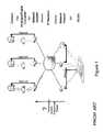
- FIG. 1shows the transmission of a Genlock signal via an IP network in a video studio environment.
- the camerasare connected to analogue/digital converters that are connected to network adaptors, themselves linked by Ethernet to an IP network.
- a studio console, as well as possibly other studio elements,is connected to the IP network by means of network adaptors.
- the question that is presented by such a systemis the following: How to transmit the Genlock signal between the cameras and the studio console and/or other studio elements so that the Genlock signal at reception is rigorously in frequency and in phase with the Genlock signal at transmission?
- the 61588 IEC standardwas designed to supply a synchronized clock in a multi-vendor distributed computing system. Such a clock is useful for coordinating activities, such as for example, an industrial process, or for correlating data measurements in a packet communications network.
- a typical applicationis the synchronisation of a Genlock video signal on different cameras connected to the network.
- the prior artdiscloses, through the American patent U.S. Pat. No. 5,805,602 (Bell Atlantic Network Services), a network surveillance system for variation in cell delay.
- This American patentdescribes an arrangement (device and method) to monitor the jitter caused during the transport of digitally coded information in a packet switching network, and to manage the functioning of the network according to the jitter detected.
- the jitter detectedis used to determine if a corrective action is necessary, such as a re-routing of network traffic or the implementation of network maintenance operations.
- the arrangement describeddetects the PCR (Program Clock Reference) values of an MPEG encoded transport stream. Each pair of PCR values represents an expected arrival instant of a segment of the corresponding stream.
- PCRProgram Clock Reference
- a real arrival time for the corresponding stream segmentis determined in response to the detection of corresponding PCR values and an independent clock signal.
- the expected arrival time of a stream segment and the real arrival timeare correlated with an accumulation of expected and real arrival times of stream segments of data packets received previously in order to determine the jitter in the digital data stream.
- the jitteris corrected by a combination of buffering and recalibration of the PCR value with the corrected values coincidental with the real arrival time of the stream segments.
- the method and the device described in this American patentsuggests comparing the expected time of reception of a packet, reflected by the PCR value, with the observed time of packet arrival, calculated using a time base independent of the transmission time base local to the reception device. The comparison was based on an independent local counter. The PCR received in the local time base is converted (the two conversion parameters were previously calculated over a dozen samples) and compared with the value of the local counter at the moment of reception. The difference provides the evaluated jitter.
- the invention of this American patentonly enables frequency synchronisation, and does not enable phase synchronisation of two remote items of equipment.
- the invention of this American patentis limited to localized jitter correction (column 19, line 21) which implies that phase synchronisation is not possible.
- the phase synchronisation of two time basesis necessary for certain applications, for example the synchronisation of items of video equipment in the direction of the Genlock.
- the invention of this American patentrelies on a time base independent of the time base to be transmitted of the reception equipment and bases its calculations on the instants of packet reception containing PCR type samples, which involves specific equipment for the detection of the arrival of these packets.
- the technical problem that this invention proposes to resolveconsists in frequency and phase synchronizing two items of equipment connected to each other by a packet communication network, while avoiding having to use specific equipment for the detection of the arrival of some packets.
- the present inventionconcerns, in the most generally accepted sense, a device able to transmit packets in a packet communication network comprising at least two stations, including:
- said received signalis of the Genlock type.
- the packet communication networkis an IP (Internet Protocol) type network.
- said device capable of transmitting packets in a packet communication networkis an item of video equipment.
- the second counter synchronised on all the network stationsis synchronised by means of the IEC 61588 standard.
- the present inventionalso relates to a device able to receive packets in a packet communication network comprising at least two stations, characterised in that it comprises:
- said device able to receive packets in a packet communication networkcomprises the means for storing together the two timestamps “Timestamp_ 1 _RX” and “Timestamp_ 2 _RX”.
- the packet communication networkis an IP (Internet Protocol) type network.
- said device able to receive packetsis a video equipment.
- the second counter synchronised on all the network stationsis synchronised by means of the IEC 61588 standard.
- said device able to receive packetscomprises a filter that receives the corrected difference and controls the slave counter.
- the filter characteristicsdetermine the characteristics of a regenerated signal.
- the regenerated signalis of the Genlock type.
- FIG. 1shows the transmission of a Genlock signal via an IP network in a video studio environment
- FIG. 2shows an implementation of the method for generating a double timestamp according to the present invention.
- the main difficulty for transmission of a clock in an IP networkis due to the fact that the transmission time of a packet in the network is not constant. Consequently, there is always a time difference between the instant when the packet is received and the instant when it was meant to be received. The difference corresponds to the transmission “jitter”. Its average is null but, for each packet, the value is not null.
- the problemis that, very often, the time information contained in the packet is calculated according to its forecast arrival time. The actual arrival time is different from the forecast arrival time, and the difference is the jitter value for that packet. Consequently, the time information contained in the packet is tainted with an error whose value is the jitter value.
- the difficultyno longer exists if it is possible to calculate the transmission delay for each packet. This is possible if another timestamp from a network clock that is assumed to be already synchronised by other means, such as the IEC 61588 standard for example, is added to each video clock timestamp.
- the second timestampevaluates the transmission time of the packet transporting the first timestamp and enables a correction as if the packet had been transmitted without jitter.
- a timestamp of another counterreferred to as the network counter, that is already synchronized in the packet communication network by other means, such as that described in the IEC 61588 standard for example.
- the two timestampsform a single and coherent information field, the second timestamp value (of the network counter).
- FIG. 2shows how the principle of a double timestamp is used for the synchronization of video counters.
- a Genlock video signalOn the transmission side, from a Genlock video signal are first derived a frequency and phase that drive and reinitialise the video counter. This video counter is called the master video counter. At regular intervals, the value of the video counter is sampled to generate a “Timestamp 1 tx ” (“Timestamp_ 1 Tx” on FIG. 2 ) At exactly the same moment, the network counter is also sampled to generate a “Timestamp_ 2 tx ” (“Timestamp_ 2 Tx” on FIG. 2 ). “Timestamp_ 1 tx ” and “Timestamp_ 2 tx ” are transmitted together in the network to the reception side.
- the slave video counterOn the reception side, there is also a video counter that is referred to as the slave video counter.
- the objectiveis to synchronize the slave video counter on the master video counter.
- the Genlock signal that is regenerated from the slave video counterwill then be synchronised on the Genlock signal driving the master video counter.
- the video counter and the network counterare regularly sampled, generating a “Timestamp_ 1 rx ” (“Timestamp_ 1 Rx” in FIG. 2 ) and a “Timestamp_ 2 rx ” (“Timestamp_ 2 Rx” in FIG. 2 ) that are stored together.
- the instant of the generation of the timestampscannot be synchronized between the emission side and reception side.
- the difference between the “Timestamp_ 2 tx ” and “Timestamp_ 2 rx ”is used to correct (subtract from) the difference between the “Timestamp_ 1 tx ” and the “Timestamp_ 1 rx ”.
- the corrected differenceis equal to zero. If the corrected difference is not equal to zero, the frequency at which the slave counter counts must be modified.
- a filterreceives the corrected differences and is responsible for controlling the frequency of the slave video counter. The filter characteristics determine the characteristics of the regenerated Genlock signal.
Landscapes
- Engineering & Computer Science (AREA)
- Multimedia (AREA)
- Signal Processing (AREA)
- Computer Security & Cryptography (AREA)
- Data Exchanges In Wide-Area Networks (AREA)
- Synchronisation In Digital Transmission Systems (AREA)
- Closed-Circuit Television Systems (AREA)
Abstract
Description
- means for receiving a signal,
- means for deriving a frequency and a phase from said received signal,
- means for initialising a counter, referred to as the master counter, by means of the derived frequency and phase,
- means for sampling the master counter value at regular intervals,
- means for generating a first temporal timestamp from a sampled value of the master counter,
- means for sampling a second counter synchronised with all the stations of the network at the same instant as the sampling of the master counter,
- means for generating a second temporal timestamp from a sample value of the of the second counter,
- means for transmitting together the two temporal timestamps in the network.
- means for sampling the value of a first counter referred to as the slave counter, at regular intervals.
- means for generating a first temporal timestamp “Timestamp1_RX” from a sampled value of the slave counter,
- means for sampling a second counter synchronised with all the stations of the network at the same instant as the sampling of the slave counter,
- means for generating a second temporal timestamp “Timestamp_2_RX” from the sampled value of the second counter,
- means for, on reception of a packet comprising two timestamps “Timestamp1 TX” and “Timestamp2_TX” and network, correcting the difference between “Timestamp1 TX” and “Timestamp2_RX” by difference between “Timestamp_2_TX” and “Timestamp_2_RX” and
- means for controlling the slave counter according to said corrected difference.
Claims (17)
Applications Claiming Priority (3)
| Application Number | Priority Date | Filing Date | Title |
|---|---|---|---|
| FR0650836AFR2898452A1 (en) | 2006-03-13 | 2006-03-13 | METHOD FOR GENERATING A DOUBLE TEMPORAL DESCRIPTOR FOR TRANSMITTING A GENLOCK SIGNAL OVER AN IP NETWORK |
| FR0650836 | 2006-03-13 | ||
| PCT/FR2007/050914WO2007104888A2 (en) | 2006-03-13 | 2007-03-12 | Generating and operating a double temporal descriptor for transmitting a synchronizing signal in a packet network |
Publications (2)
| Publication Number | Publication Date |
|---|---|
| US20090034560A1 US20090034560A1 (en) | 2009-02-05 |
| US7903694B2true US7903694B2 (en) | 2011-03-08 |
Family
ID=37546671
Family Applications (1)
| Application Number | Title | Priority Date | Filing Date |
|---|---|---|---|
| US12/225,019Expired - Fee RelatedUS7903694B2 (en) | 2006-03-13 | 2007-03-12 | Generation and operation of a double timestamp for transmitting a synchronizing signal in a packet switching network |
Country Status (5)
| Country | Link |
|---|---|
| US (1) | US7903694B2 (en) |
| EP (1) | EP1994765B1 (en) |
| JP (1) | JP4875716B2 (en) |
| FR (1) | FR2898452A1 (en) |
| WO (1) | WO2007104888A2 (en) |
Cited By (5)
| Publication number | Priority date | Publication date | Assignee | Title |
|---|---|---|---|---|
| US20100118870A1 (en)* | 2007-06-12 | 2010-05-13 | Thomson Licensing | Phase control of a synchronization signal in a packet switching network |
| US8817117B2 (en) | 2010-03-31 | 2014-08-26 | Sony Corporation | Camera system, signal delay amount adjusting method and program |
| US9032459B2 (en) | 2010-03-31 | 2015-05-12 | Sony Corporation | Camera system, signal delay amount adjusting method and program |
| US9979991B2 (en) | 2014-11-17 | 2018-05-22 | Skotel Corporation | Method and apparatus for deterministic date and time alignment of media signals and generation of time-related labels |
| US20200133330A1 (en)* | 2019-03-05 | 2020-04-30 | Intel Corporation | Timestamp alignment across multiple computing nodes |
Families Citing this family (2)
| Publication number | Priority date | Publication date | Assignee | Title |
|---|---|---|---|---|
| FR2911460A1 (en)* | 2007-01-16 | 2008-07-18 | Thomson Licensing Sas | RAPID INITIALIZATION OF THE VIDEO TIME BASE GENERATING A SYNCHRONIZATION SIGNAL IN A PACKET SWITCHED NETWORK |
| CN102439926A (en)* | 2009-04-14 | 2012-05-02 | Ati技术无限责任公司 | Embedded clock recovery |
Citations (10)
| Publication number | Priority date | Publication date | Assignee | Title |
|---|---|---|---|---|
| US5487067A (en)* | 1993-04-01 | 1996-01-23 | Sony Corporation | Audio data communications |
| US5805602A (en) | 1995-09-25 | 1998-09-08 | Bell Atlantic Network Services, Inc. | Network monitoring system for cell delay variation |
| US20020061012A1 (en)* | 1999-04-13 | 2002-05-23 | Thi James C. | Cable modem with voice processing capability |
| US20020174105A1 (en)* | 1996-07-30 | 2002-11-21 | Carlos De La Huerga | Method for storing records at easily accessible addresses |
| US6675326B1 (en)* | 2000-07-11 | 2004-01-06 | Matsushita Electric Industrial Co., Ltd. | Method and apparatus for detecting a data receiving error |
| US20050008040A1 (en)* | 2003-06-11 | 2005-01-13 | Burkhard Becker | Apparatus and method for time control of the processing of a radio signal in a mobile station |
| US20060013262A1 (en)* | 2004-07-15 | 2006-01-19 | Denis Downey | Method and system for synchronizing separated edge QAM devices located remotely from a CMTS |
| US20070286245A1 (en)* | 2006-03-31 | 2007-12-13 | Masahiro Yamada | Digital signal processing apparatus and data stream processing method |
| US7548600B2 (en)* | 2005-07-28 | 2009-06-16 | Sercel | Apparatus and method for compensating the drift of a local clock used as sampling frequency |
| US7711328B1 (en)* | 2005-06-29 | 2010-05-04 | Xilinx, Inc. | Method of and circuit for sampling a frequency difference in an integrated circuit |
Family Cites Families (1)
| Publication number | Priority date | Publication date | Assignee | Title |
|---|---|---|---|---|
| US7492732B2 (en)* | 2005-11-01 | 2009-02-17 | Nortel Networks Limited | Differential clock recovery in packet networks |
- 2006
- 2006-03-13FRFR0650836Apatent/FR2898452A1/enactivePending
- 2007
- 2007-03-12JPJP2008558863Apatent/JP4875716B2/ennot_activeExpired - Fee Related
- 2007-03-12USUS12/225,019patent/US7903694B2/ennot_activeExpired - Fee Related
- 2007-03-12WOPCT/FR2007/050914patent/WO2007104888A2/enactiveApplication Filing
- 2007-03-12EPEP07731730.3Apatent/EP1994765B1/ennot_activeCeased
Patent Citations (10)
| Publication number | Priority date | Publication date | Assignee | Title |
|---|---|---|---|---|
| US5487067A (en)* | 1993-04-01 | 1996-01-23 | Sony Corporation | Audio data communications |
| US5805602A (en) | 1995-09-25 | 1998-09-08 | Bell Atlantic Network Services, Inc. | Network monitoring system for cell delay variation |
| US20020174105A1 (en)* | 1996-07-30 | 2002-11-21 | Carlos De La Huerga | Method for storing records at easily accessible addresses |
| US20020061012A1 (en)* | 1999-04-13 | 2002-05-23 | Thi James C. | Cable modem with voice processing capability |
| US6675326B1 (en)* | 2000-07-11 | 2004-01-06 | Matsushita Electric Industrial Co., Ltd. | Method and apparatus for detecting a data receiving error |
| US20050008040A1 (en)* | 2003-06-11 | 2005-01-13 | Burkhard Becker | Apparatus and method for time control of the processing of a radio signal in a mobile station |
| US20060013262A1 (en)* | 2004-07-15 | 2006-01-19 | Denis Downey | Method and system for synchronizing separated edge QAM devices located remotely from a CMTS |
| US7711328B1 (en)* | 2005-06-29 | 2010-05-04 | Xilinx, Inc. | Method of and circuit for sampling a frequency difference in an integrated circuit |
| US7548600B2 (en)* | 2005-07-28 | 2009-06-16 | Sercel | Apparatus and method for compensating the drift of a local clock used as sampling frequency |
| US20070286245A1 (en)* | 2006-03-31 | 2007-12-13 | Masahiro Yamada | Digital signal processing apparatus and data stream processing method |
Non-Patent Citations (1)
| Title |
|---|
| Search Report Dated Sep. 18, 2007. |
Cited By (8)
| Publication number | Priority date | Publication date | Assignee | Title |
|---|---|---|---|---|
| US20100118870A1 (en)* | 2007-06-12 | 2010-05-13 | Thomson Licensing | Phase control of a synchronization signal in a packet switching network |
| US8170012B2 (en)* | 2007-06-12 | 2012-05-01 | Thomson Licensing | Phase control of a synchronization signal in a packet switching network |
| US8817117B2 (en) | 2010-03-31 | 2014-08-26 | Sony Corporation | Camera system, signal delay amount adjusting method and program |
| US9032459B2 (en) | 2010-03-31 | 2015-05-12 | Sony Corporation | Camera system, signal delay amount adjusting method and program |
| US9979991B2 (en) | 2014-11-17 | 2018-05-22 | Skotel Corporation | Method and apparatus for deterministic date and time alignment of media signals and generation of time-related labels |
| US20200133330A1 (en)* | 2019-03-05 | 2020-04-30 | Intel Corporation | Timestamp alignment across multiple computing nodes |
| US11693448B2 (en)* | 2019-03-05 | 2023-07-04 | Intel Corporation | Timestamp alignment across multiple computing nodes |
| US12222750B2 (en) | 2019-03-05 | 2025-02-11 | Intel Corporation | Timestamp alignment across multiple computing nodes |
Also Published As
| Publication number | Publication date |
|---|---|
| EP1994765B1 (en) | 2017-01-18 |
| WO2007104888A3 (en) | 2007-12-06 |
| EP1994765A2 (en) | 2008-11-26 |
| FR2898452A1 (en) | 2007-09-14 |
| JP4875716B2 (en) | 2012-02-15 |
| US20090034560A1 (en) | 2009-02-05 |
| JP2009530884A (en) | 2009-08-27 |
| WO2007104888A2 (en) | 2007-09-20 |
Similar Documents
| Publication | Publication Date | Title |
|---|---|---|
| US6493832B1 (en) | Communication apparatus which handles a time stamp | |
| US7903694B2 (en) | Generation and operation of a double timestamp for transmitting a synchronizing signal in a packet switching network | |
| US8073060B2 (en) | Video synchronization | |
| CA2684227C (en) | Improved method, system and apparatus for synchronizing signals | |
| US8767778B2 (en) | Method, system and apparatus for synchronizing signals | |
| US8774287B2 (en) | Precise compensation of video propagation duration | |
| US20090175271A1 (en) | Transmitting A Synchronizing Signal In A Packet Network | |
| US8737411B2 (en) | Delivery delay compensation on synchronised communication devices in a packet switching network | |
| US7778173B2 (en) | Clock recovery algorithm for remultiplexing MPEG-2 SPTSs and/or MPTSs in the presence of network jitter | |
| EP2153663B1 (en) | Automatic compensation of a delay of a synchronization signal in a packet switching network | |
| US20040170199A1 (en) | Method and system for compensating for timing violations of a multiplex of at least two media packet streams | |
| KR101151390B1 (en) | Method for transmitting packets in a transmission system | |
| JP5375021B2 (en) | Clock recovery system and method | |
| US8170012B2 (en) | Phase control of a synchronization signal in a packet switching network | |
| US8218577B2 (en) | Secure mechanism for transmitting counter value in the context of transmission of a synchronizing signal in a packet network | |
| US8223805B2 (en) | Method and device for automatically compensating a phase shift on a synchronisation signal received by an item of remote equipment | |
| US20230327970A1 (en) | Integrated network evaluation troubleshooting tool | |
| JP4947447B2 (en) | Real-time data transmission system | |
| JP2025506870A (en) | Method for measuring timing holdover performance in an R-PHY system - Patents.com | |
| JP5397034B2 (en) | Packet transmission apparatus and method | |
| WO2012066832A1 (en) | Ip receiver device, ip transmitter device, and ts receiver device | |
| Kovach | Next Generation Feature Roadmap for IP-Based Range Architectures | |
| KR20060049714A (en) | Device and method for multiplexing associated with a coding device |
Legal Events
| Date | Code | Title | Description |
|---|---|---|---|
| AS | Assignment | Owner name:THOMSON LICENSING, FRANCE Free format text:ASSIGNMENT OF ASSIGNORS INTEREST;ASSIGNORS:DEFRANCE, SERGE;TAPIE, THIERRY;MACE, GAEL;REEL/FRAME:021553/0360;SIGNING DATES FROM 20080804 TO 20080818 Owner name:THOMSON LICENSING, FRANCE Free format text:ASSIGNMENT OF ASSIGNORS INTEREST;ASSIGNORS:DEFRANCE, SERGE;TAPIE, THIERRY;MACE, GAEL;SIGNING DATES FROM 20080804 TO 20080818;REEL/FRAME:021553/0360 | |
| STCF | Information on status: patent grant | Free format text:PATENTED CASE | |
| FPAY | Fee payment | Year of fee payment:4 | |
| MAFP | Maintenance fee payment | Free format text:PAYMENT OF MAINTENANCE FEE, 8TH YEAR, LARGE ENTITY (ORIGINAL EVENT CODE: M1552); ENTITY STATUS OF PATENT OWNER: LARGE ENTITY Year of fee payment:8 | |
| AS | Assignment | Owner name:MAGNOLIA LICENSING LLC, TEXAS Free format text:ASSIGNMENT OF ASSIGNORS INTEREST;ASSIGNOR:THOMSON LICENSING S.A.S.;REEL/FRAME:053570/0237 Effective date:20200708 | |
| FEPP | Fee payment procedure | Free format text:MAINTENANCE FEE REMINDER MAILED (ORIGINAL EVENT CODE: REM.); ENTITY STATUS OF PATENT OWNER: LARGE ENTITY | |
| LAPS | Lapse for failure to pay maintenance fees | Free format text:PATENT EXPIRED FOR FAILURE TO PAY MAINTENANCE FEES (ORIGINAL EVENT CODE: EXP.); ENTITY STATUS OF PATENT OWNER: LARGE ENTITY | |
| STCH | Information on status: patent discontinuation | Free format text:PATENT EXPIRED DUE TO NONPAYMENT OF MAINTENANCE FEES UNDER 37 CFR 1.362 | |
| FP | Lapsed due to failure to pay maintenance fee | Effective date:20230308 |