US7903494B2 - Wireless sensor interface with mobile terminal satellite modem and global location system - Google Patents
Wireless sensor interface with mobile terminal satellite modem and global location systemDownload PDFInfo
- Publication number
- US7903494B2 US7903494B2US12/333,048US33304808AUS7903494B2US 7903494 B2US7903494 B2US 7903494B2US 33304808 AUS33304808 AUS 33304808AUS 7903494 B2US7903494 B2US 7903494B2
- Authority
- US
- United States
- Prior art keywords
- wireless device
- wireless
- sensor
- satellite modem
- mobile terminal
- Prior art date
- Legal status (The legal status is an assumption and is not a legal conclusion. Google has not performed a legal analysis and makes no representation as to the accuracy of the status listed.)
- Active, expires
Links
- 230000006854communicationEffects0.000claimsabstractdescription31
- 238000004891communicationMethods0.000claimsabstractdescription31
- 238000000034methodMethods0.000claimsabstractdescription23
- 230000008569processEffects0.000claimsdescription15
- 238000012544monitoring processMethods0.000claimsdescription5
- 230000002618waking effectEffects0.000claims1
- 230000007958sleepEffects0.000description8
- 238000005259measurementMethods0.000description5
- 230000008859changeEffects0.000description4
- 238000013480data collectionMethods0.000description4
- 230000001360synchronised effectEffects0.000description4
- 230000005540biological transmissionEffects0.000description3
- 238000012545processingMethods0.000description3
- 238000012546transferMethods0.000description3
- 238000001514detection methodMethods0.000description2
- 238000007726management methodMethods0.000description2
- 230000007175bidirectional communicationEffects0.000description1
- 230000003111delayed effectEffects0.000description1
- 238000011161developmentMethods0.000description1
- 238000009434installationMethods0.000description1
- 238000009413insulationMethods0.000description1
- 230000010354integrationEffects0.000description1
- 238000012423maintenanceMethods0.000description1
- 230000007246mechanismEffects0.000description1
- 230000000737periodic effectEffects0.000description1
- 230000005855radiationEffects0.000description1
- 230000004044responseEffects0.000description1
- 238000012552reviewMethods0.000description1
- 239000000126substanceSubstances0.000description1
- XLYOFNOQVPJJNP-UHFFFAOYSA-NwaterSubstancesOXLYOFNOQVPJJNP-UHFFFAOYSA-N0.000description1
Images


Classifications
- G—PHYSICS
- G01—MEASURING; TESTING
- G01S—RADIO DIRECTION-FINDING; RADIO NAVIGATION; DETERMINING DISTANCE OR VELOCITY BY USE OF RADIO WAVES; LOCATING OR PRESENCE-DETECTING BY USE OF THE REFLECTION OR RERADIATION OF RADIO WAVES; ANALOGOUS ARRANGEMENTS USING OTHER WAVES
- G01S5/00—Position-fixing by co-ordinating two or more direction or position line determinations; Position-fixing by co-ordinating two or more distance determinations
- G01S5/0009—Transmission of position information to remote stations
- G01S5/0018—Transmission from mobile station to base station
- G01S5/0027—Transmission from mobile station to base station of actual mobile position, i.e. position determined on mobile
Definitions
- the present inventionrelates generally to asset tracking and monitoring and, more particularly, to a wireless sensor interface with mobile terminal satellite modem and global location system.
- Tracking mobile assetsrepresents a growing enterprise as companies seek increased visibility into the status of a service fleet (e.g., long-haul delivery fleet). Visibility into the status of a service fleet can be gained through mobile terminals that are affixed to service vehicles. These mobile terminals can be designed to generate position information that can be used to update status reports that are provided to customer representatives.
- a service fleete.g., long-haul delivery fleet.
- the mobile terminalcan generate position information through the reception of satellite position signals such as that generated by the GPS satellite network. Generated status reports are transmitted to the centralized facility using a return link via a communications satellite.
- the status reportscan also include sensor data that is generated by sensors affixed to the service vehicle (e.g., inside a trailer). This sensor data would enable the company to discern the condition of cargo being transported, the condition of the service vehicle, the occurrence of any events at the service vehicle, etc.
- Sensor datacan be obtained using sensors that are positioned at various points on a service vehicle. Connection of this collection of sensors to the mobile terminal can represent a substantial expense. Accordingly, what is needed is a mechanism that reduces the costs of obtaining such sensor data, while also minimizing the overall power required by the monitoring system.
- a wireless sensor interface with mobile terminal satellite modem and global location systemsubstantially as shown in and/or described in connection with at least one of the figures, as set forth more completely in the claims.
- FIG. 1illustrates an embodiment of a satellite communications network that enables the monitoring of remote assets using a collection of sensors.
- FIG. 2illustrates an embodiment of a wireless local area network.
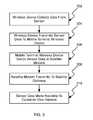
- FIG. 3illustrates a flowchart of a process of reporting sensor data to a centralized facility.
- FIG. 4illustrates an embodiment of a wireless device that is coupled to a sensor.
- FIG. 5illustrates a flowchart of a process of communication method that conserves power.
- the asset-tracking systemcan also include one or more sensors that are affixed to those assets.
- Various sensor typescan be used. For example, volume sensors, temperature sensors, chemical sensors, radiation sensors, weight sensors, light sensors, water sensors, etc. can be used to report the condition of cargo being transported.
- truck cab ID indicators, odometer sensors, wheel sensors, vibration sensors, etc.can be used to report the condition of the service vehicle. In general, these various sensors can be used to report status information or the occurrence of any events at the service vehicle.
- sensors within a trailerare especially valuable when considering the cargo that is being transported. These sensors can provide valuable information relating to the existence, condition of, and access to such cargo. For this reason, significant efforts have been made to capture and report sensor data to a centralized facility.
- sensorsneed an interface to a mobile terminal that reports the position and sensor information via wireless communication (e.g., satellite communication) to a centralized facility.
- wireless communicatione.g., satellite communication
- the interface between the sensors and the mobile terminalrepresents a significant technical and economic challenge.
- the mobile terminalcould require extensive connections to sensors that can be positioned at various points on the cab/trailer (e.g., on the trailer door, inside the trailer, on the wheels, in the cab, etc.).
- sensorse.g., on the trailer door, inside the trailer, on the wheels, in the cab, etc.
- cable connections between this mobile terminal and the various sensorscan add a substantial expense (e.g., hundreds of dollars) to the overall cost of deployment.
- the cable connectionscan also represent technical challenges. For example, cable connections between a roof-mounted mobile terminal and a sensor located inside the trailer would require that one or more holes be cut into the trailer compartment. While these holes would facilitate the passage of sensor cabling into the trailer compartment, the holes would also raise significant weatherproofing issues. Moreover, the holes could also raise insulation issues when considering refrigerated trailer compartments. In another example, cable connections between a roof-mounted mobile terminal and a sensor located in the cab would require additional cabling or integration within existing cabling such as the cab-trailer electrical interface.
- connections between a mobile terminal and one or more sensors affixed to the tracked assetcan result in significant cost and/or development issues.
- the principles of the present inventionare designed to meet these needs by not only implementing a wireless connection between a mobile terminal and one or more sensors that facilitates two-way communication, but also operating such a wireless network in manner that minimizes the power required the mobile terminal and sensor devices.
- FIG. 1illustrates an embodiment of a satellite network 100 that includes operations gateway 102 , communicating with mobile terminal 120 on an asset. Communication between operations gateway 102 and mobile terminal 120 is facilitated by satellite gateway 104 at the ground station and satellite modem 122 in mobile terminal 120 . Both satellite gateway 104 and satellite modem 122 facilitate communication using one forward and one return link (frequency) over communications satellite 106 .
- satellite gateway 104 and satellite modem 122facilitate communication using one forward and one return link (frequency) over communications satellite 106 .
- the satellite communicationis implemented in a time division multiple access (TDMA) structure, which consists of 57600 time slots each day, per frequency or link, where each slot is 1.5 seconds long.
- operations gateway 102sends a message or packet to mobile terminal 120 on one of the 1.5 second slots.
- mobile terminal 120Upon receipt of this message or packet, mobile terminal 120 would then perform a GPS collection (e.g., code phase measurements) using Global Locating System (GLS) module 124 or to perform sensor measurements and transmit the data back to operations gateway 102 on the return link, on the same slot, delayed by a fixed time defined by the network.
- the fixed delaydefines a length of time that enables mobile terminal 120 to decode the forward packet, perform the data collection and processing, and build and transmit the return packet.
- mobile terminal 120can be configured to produce periodic status reports. In this configuration, mobile terminal 120 would wake up periodically, search for its assigned forward slot, perform data collection and processing, and transmit the status report on the assigned return slot. In another embodiment, mobile terminal 120 can be configured to produce a status report upon an occurrence of an event (e.g., door opening, motion detected, sensor reading, etc.). In this configuration, mobile terminal 120 would wake up upon occurrence of an event, search for an available forward slot, perform data collection and processing, and transmit the status report on the return slot corresponding to the identified available forward slot.
- an evente.g., door opening, motion detected, sensor reading, etc.
- operations gateway 102Upon receipt of a status report from mobile terminal 120 , operations gateway 102 passes the information to operations center 112 , where the information is processed and passed to a customer via the Internet.
- operations center 112Upon receipt of a status report from mobile terminal 120 , operations gateway 102 passes the information to operations center 112 , where the information is processed and passed to a customer via the Internet.
- operations center 112Upon receipt of a status report from mobile terminal 120 , operations gateway 102 passes the information to operations center 112 , where the information is processed and passed to a customer via the Internet.
- U.S. Pat. No. 6,725,158entitled “System and Method for Fast Acquisition Position Reporting Using Communication Satellite Range Measurement,” which is incorporated herein by reference in its entirety.
- the principles of the present inventioncan also be applied to other satellite communications systems as well as to terrestrial communications systems.
- mobile terminal 120can also collect sensor measurements from sensors 130 that are positioned at various points on the asset being tracked. Transmission of sensor information from sensors 130 to mobile terminal 120 is facilitated by a low-power, low-cost wireless interface. As illustrated the wireless interface uses wireless device WD( 1 ) that is coupled to satellite modem 122 , and wireless devices WD( 2 )-WD(n) that are coupled to respective sensors 130 . The wireless network formed by wireless devices WD( 1 )-WD(n) enables mobile terminal 120 to interface to the plurality of wireless sensors 130 . It should be noted that this wireless network can operate independently from the standard functions of mobile terminal 120 .
- wireless device WD( 1 )is integrated on the same hardware as satellite modem 122 .
- wireless device WD( 1 )is on separate hardware from satellite modem 122 and uses a hardwired interface such as a serial communications interface.
- the wireless interfaceuses wireless devices that can be configured as master or slave devices.
- FIG. 2illustrates an embodiment of a master-slave configuration for the wireless devices.
- wireless device WD( 1 ) in mobile terminal 120is configured as a master device, while wireless devices WD( 2 )-WD(n) that are coupled to individual sensors are configured as slave devices.
- This master-slave configurationenables independent communication between the wireless devices.
- Each wireless devicecan be an independently addressable unit having its own processor, power management, sleep timers and other apparatus that allows it to perform low data rate communications, conserve power and reduce cost. It is a feature of the present invention that this wireless interface has the capability to transfer binary data in both directions to and from a sensor device. In one embodiment, slave devices only transmit in acknowledgment from a request from a master device. This type of half-duplex communication exhibits good performance in low data rate systems and for avoiding collisions.
- FIG. 3illustrates a flowchart of communication between a sensor and the customer interface.
- the processbegins at step 302 , where a wireless device (e.g., slave wireless device WD( 2 )) collects data from an attached sensor 130 .
- this data collectionis facilitated by a hardwired interface, such as a serial interface.
- the sensoris integrated with the wireless device.
- the wireless deviceAfter the sensor data is collected by the wireless device, at step 304 , the wireless device then transmits the sensor data to the mobile terminal wireless device (e.g., master wireless device WD( 1 )). At step 306 , the mobile terminal wireless device then forwards the information to satellite modem 122 . At step 308 , satellite modem 122 transmits the information to satellite gateway 104 via satellite 106 . From here, at step 310 , the sensor data can then be made available to the customer over a customer interface via the Internet.
- the mobile terminal wireless devicee.g., master wireless device WD( 1 )
- the mobile terminal wireless devicethen forwards the information to satellite modem 122 .
- satellite modem 122transmits the information to satellite gateway 104 via satellite 106 . From here, at step 310 , the sensor data can then be made available to the customer over a customer interface via the Internet.
- datacan also be sent to the sensor device.
- a customercan send data to a sensor device from the web interface in the opposite direction of that described in the process of FIG. 3 .
- This direction of communication to the sensor deviceenables the customer or system operator to configure the sensor device through a wireless interface.
- device configurationcan include, but is not limited to, its operating mode (such as master or slave device), baud rate, power level, channel selection, wake up interval, status requests, etc.
- all of the wireless interface network's configurable parameterscan be set or changed either over-the-air from the gateway, or through some other interface, such as a wired interface using a configuration terminal.
- the local area wireless interfacecan enable system devices to be in a low power sleep mode most of the time, and only transmit for a short duration of time on a specified frequency or channel to conserve power.
- the local area wireless interfaceuses a TDMA type communication protocol.
- FIG. 4illustrates an embodiment of a wireless device that has the ability to enter a low power state, and wake at a programmed time.
- wireless device 400includes microprocessor 402 , which is used to control the various functions, power management 404 , which is used to power down and enter a low power state, real time clock 406 , which wakes or powers-up the unit at a pre-determined time, input/output 408 , which allows an interface to other devices, sensors, transducers, including the mobile terminal, and RF module 410 , which performs the actual wireless communications.
- RF module 410can be simple or complex. In one embodiment, RF module 410 would include a computer, a low-layer waveform and modulation technique, and its own protocol that could detect and correct errors and perform retries in order to reliably transmit and receive data.
- the processbegins at step 502 where master device (e.g., WD( 1 )) is awakened and receives data from its I/O port for a particular slave device (e.g., WD( 2 )) and a sensor 130 that is attached to that slave device.
- the master deviceprepares this information for delivery and stores it.
- the master deviceprograms a sleep timer to wake at the correct time then powers down. This wake time is the time the master device and the network protocol expects the receiving slave device to wake, assuming it is synchronized to the network.
- the master devicecan also compensate for time drifts and other physical layer issues.
- the master unitawakens at the scheduled time and transmits the information to the slave device.
- the master devicedetermines whether an acknowledgment is received. In one embodiment, the slave device responds immediately. In another embodiment, both the master and slave device go back into a sleep mode and wake shortly thereafter for the slave device to send the acknowledgement.
- step 508If it is determined, at step 508 , that the acknowledgment is not received, then the protocol would instruct both master and slave devices to try again at a later prescribed time, or wait for the next scheduled wakeup interval, depending on it configuration. If it is determined, at step 508 , that the acknowledgment is received, then the data transfer process ends and the slave device would deliver the data to its attached sensor through its I/O port.
- this processcan be used to transmit configuration information to a sensor device. In another example, this process can be used to transmit a status request to a sensor device, wherein the sensor device's response would include measurement data taken by the sensor. This example illustrates an example of scheduled reporting through polling of the sensor device.
- Event reportingcan also be supported by the network protocol.
- a sensor eventcan represent a detected change in monitored status (e.g., door opening, emptying of cargo, change in temperature, etc.), a detected change in operating state, or any other change detectable by a sensor.
- Information reflective of this detected eventcan then be prepared for transmission to the master device by the slave device, wherein the slave device sleeps until a scheduled time for transmission to the master device.
- the network protocolwould enable the master and slave devices to sleep until a scheduled time when communication between the pair of devices on a known channel or frequency is expected to occur. This scheduled time would support a short communication between the two devices, which would ensure that the devices are only awakened for a minimal amount of time. The remaining time, which represents the vast majority of time, would be spent in a low power sleep mode.
- the networkis synchronized such that the wake-up times are known by the individual devices. If the network is not synchronized, or the wake-up times are different, and/or channels or frequencies are different, the network protocol would enter a synchronization mode. In one embodiment, the synchronization process has all devices wake at some pseudo-random interval and channel until they find each other. The data transmitted would be small in order to minimize time and power consumption, while maximizing the probability of a hit or detection. Also, devices can be designed to slow themselves down or backoff after a period of time when it determines it is past the time where it normally synchronizes. This conserves power especially if the device has failed.
- the synchronization processcan also be expedited given some known information about the other devices that can or should be on the network such as their ID or group number.
- This informationcan be used in the network protocol, and in the synchronization process, particularly in the pseudo-random wake-up portion to increase the likelihood of a hit on both time and frequency.
- this informationcan be used to force all devices onto the same channel or frequency, which eliminates the need to search the other frequencies, and reduces the synchronization time.
- This informationcan also be pre-programmed into each device during installation.
- other informationcan be added at the factory, such as initializing the real time clocks such that the algorithm can pick times and frequencies based on the day to increase the probability of a hit, and reduce synchronization time.
- Synchronizationcan be further expedited by extraneous events such as manually pushing a button at approximately the same time on all devices on the network to initiate a momentary high rate of retries on the network.
- This type of eventcan cause all devices to use one pre-determined frequency and have each device remain powered continuously for a short duration, enough to allow all devices to enter this state and synchronize. While this mode consumes more power, it only needs to be in this mode for a short time since all the devices know that the others are also in this mode and awake.
- the master and the network protocolcan assign each device to a particular channel or frequency and wakeup time or slot. It can also broadcast additional information after the initial synchronization which will help each device more quickly synchronize in the future if it loses it's synchronization.
- the process that maintains synchronizationcan also use dithering to vary the wakeup times and frequencies on each wakeup in order to avoid collisions with other networks that may be within the same RF range.
- Each individual networkcan also be designed to communicate to a global master device to send and receive broadcast information.
- a global master devicecould be a hand-held diagnostic tool that acts as a master device except that it doesn't sleep and can continuously broadcast out to all devices since it has no power constraints. By continuously broadcasting, such a device can quickly reach all the devices in any network within RF range by waiting until their next wake up, where they can receive the broadcast information. When a device wakes on its scheduled time, which is completely different and random from devices on other networks, it can receive the broadcast information. This information would instruct the devices on what to do. One example is to command all devices to report their presence and status. The protocol can support this type of broadcast by allowing acknowledgements and retries.
- a hand held devicecan be used, for example, in a trucking yard to detect all networks within the yard to do an inventory. It can also be used to reprogram or reconfigure networks. This function of the network protocol allows devices to operate in different modes in order to perform maintenance, diagnostics, and operations.
- various network protocolscan be designed to operate the low-power local-area wireless network of the present invention. While the network protocol details can vary depending on the implementation, the network protocol is designed to satisfy a variety of functions other than the basic communication between master and slave devices. Some of the functions supported can include transferring data to and from a specific device, communicating scheduled and event data, auto detection of devices, configuring and reading status of devices, allowing diagnostic tools to use the network for configuration and re-programming, error handling, retrying failed communications, detecting collisions or interference from other low-power local-area wireless network, re-synchronizing timing of the devices, and automatically changing channels or frequencies.
Landscapes
- Physics & Mathematics (AREA)
- Engineering & Computer Science (AREA)
- General Physics & Mathematics (AREA)
- Radar, Positioning & Navigation (AREA)
- Remote Sensing (AREA)
- Mobile Radio Communication Systems (AREA)
Abstract
Description
Claims (20)
Priority Applications (4)
| Application Number | Priority Date | Filing Date | Title |
|---|---|---|---|
| US12/333,048US7903494B2 (en) | 2005-09-12 | 2008-12-11 | Wireless sensor interface with mobile terminal satellite modem and global location system |
| US12/768,287US20100321171A1 (en) | 2005-09-12 | 2010-04-27 | System and Method for Satellite Aided Truck/Trailer Tracking and Monitoring |
| US13/037,449US8284629B2 (en) | 2005-09-12 | 2011-03-01 | Wireless sensor interface with mobile terminal satellite modem and global location system |
| US13/645,649US8971227B2 (en) | 2005-09-12 | 2012-10-05 | Wireless sensor interface with mobile terminal satellite modem and global location system |
Applications Claiming Priority (4)
| Application Number | Priority Date | Filing Date | Title |
|---|---|---|---|
| US71559605P | 2005-09-12 | 2005-09-12 | |
| US72154005P | 2005-09-29 | 2005-09-29 | |
| US11/518,520US7468927B1 (en) | 2005-09-12 | 2006-09-11 | Wireless sensor interface with mobile terminal satellite modem and global location system |
| US12/333,048US7903494B2 (en) | 2005-09-12 | 2008-12-11 | Wireless sensor interface with mobile terminal satellite modem and global location system |
Related Parent Applications (1)
| Application Number | Title | Priority Date | Filing Date |
|---|---|---|---|
| US11/518,520ContinuationUS7468927B1 (en) | 2005-09-12 | 2006-09-11 | Wireless sensor interface with mobile terminal satellite modem and global location system |
Related Child Applications (2)
| Application Number | Title | Priority Date | Filing Date |
|---|---|---|---|
| US12/768,287Continuation-In-PartUS20100321171A1 (en) | 2005-09-12 | 2010-04-27 | System and Method for Satellite Aided Truck/Trailer Tracking and Monitoring |
| US13/037,449ContinuationUS8284629B2 (en) | 2005-09-12 | 2011-03-01 | Wireless sensor interface with mobile terminal satellite modem and global location system |
Publications (2)
| Publication Number | Publication Date |
|---|---|
| US20090096604A1 US20090096604A1 (en) | 2009-04-16 |
| US7903494B2true US7903494B2 (en) | 2011-03-08 |
Family
ID=40134257
Family Applications (3)
| Application Number | Title | Priority Date | Filing Date |
|---|---|---|---|
| US11/518,520Active2027-07-24US7468927B1 (en) | 2005-09-12 | 2006-09-11 | Wireless sensor interface with mobile terminal satellite modem and global location system |
| US12/333,048Active2027-02-09US7903494B2 (en) | 2005-09-12 | 2008-12-11 | Wireless sensor interface with mobile terminal satellite modem and global location system |
| US13/037,449ActiveUS8284629B2 (en) | 2005-09-12 | 2011-03-01 | Wireless sensor interface with mobile terminal satellite modem and global location system |
Family Applications Before (1)
| Application Number | Title | Priority Date | Filing Date |
|---|---|---|---|
| US11/518,520Active2027-07-24US7468927B1 (en) | 2005-09-12 | 2006-09-11 | Wireless sensor interface with mobile terminal satellite modem and global location system |
Family Applications After (1)
| Application Number | Title | Priority Date | Filing Date |
|---|---|---|---|
| US13/037,449ActiveUS8284629B2 (en) | 2005-09-12 | 2011-03-01 | Wireless sensor interface with mobile terminal satellite modem and global location system |
Country Status (1)
| Country | Link |
|---|---|
| US (3) | US7468927B1 (en) |
Cited By (2)
| Publication number | Priority date | Publication date | Assignee | Title |
|---|---|---|---|---|
| US8971227B2 (en)* | 2005-09-12 | 2015-03-03 | Skybitz, Inc. | Wireless sensor interface with mobile terminal satellite modem and global location system |
| US9060337B2 (en) | 2012-03-21 | 2015-06-16 | Thermo King Corporation | Methods and systems for preserving the life of a power source of a wireless end node in a transport refrigeration system |
Families Citing this family (31)
| Publication number | Priority date | Publication date | Assignee | Title |
|---|---|---|---|---|
| US7468927B1 (en)* | 2005-09-12 | 2008-12-23 | Skybitz, Inc. | Wireless sensor interface with mobile terminal satellite modem and global location system |
| US20080129490A1 (en)* | 2006-10-06 | 2008-06-05 | Linville Jeffrey E | Apparatus and Method for Real Time Validation of Cargo Quality for Logistics Applications |
| WO2009138119A1 (en)* | 2008-05-12 | 2009-11-19 | Telefonaktiebolaget Lm Ericsson (Publ) | Tracking network resources |
| US8294573B2 (en)* | 2008-12-11 | 2012-10-23 | International Business Machines Corporation | System and method for optimizing power consumption of container tracking devices through mesh networks |
| BRPI0901457A2 (en)* | 2009-05-05 | 2011-01-18 | Uniao Brasileira De Educacao E Assistencia Mantenedora Da Puc Rs | remote environmental monitoring method and remote environmental monitoring apparatus |
| US8638236B2 (en)* | 2010-02-25 | 2014-01-28 | Qualcomm Incorporated | Methods and apparatus for applying tactile pressure sensors |
| US20110239011A1 (en) | 2010-03-26 | 2011-09-29 | Nokia Corporation | Method and apparatus for synchronizing wake-ups of offline mobile devices |
| US20130229273A1 (en)* | 2010-11-25 | 2013-09-05 | Freescale Semiconductor, Inc. | Tactile input device, microprocessor system and method for controlling a tactile input device |
| US10783481B2 (en)* | 2012-03-22 | 2020-09-22 | Fedex Corporate Services, Inc. | Systems and methods for trip management |
| US20140279230A1 (en)* | 2013-03-15 | 2014-09-18 | Service Solutions U.S. Llc | Revenue Sharing System and Method Thereof |
| US9098956B2 (en)* | 2013-09-26 | 2015-08-04 | Lytx, Inc. | Dynamic uploading protocol |
| JP6544717B2 (en)* | 2014-07-01 | 2019-07-17 | パナソニックIpマネジメント株式会社 | Power tool system |
| US9428195B1 (en) | 2014-07-24 | 2016-08-30 | Lytx, Inc. | Back-end event risk assessment with historical coaching profiles |
| US10339619B2 (en)* | 2015-08-25 | 2019-07-02 | Scott Arthur William Muirhead | Method and apparatus for presenting supply chain information to a consumer |
| US11637694B2 (en) | 2018-07-16 | 2023-04-25 | Winkk, Inc. | Secret material exchange and authentication cryptography operations |
| US10841879B2 (en)* | 2018-12-28 | 2020-11-17 | Hughes Network Systems, Llc | User terminal power savings and intelligent wake system |
| DE102019111052A1 (en)* | 2019-04-29 | 2020-10-29 | Kraiburg Austria Gmbh & Co. Kg | Method for assigning wheels to a vehicle |
| US11553337B2 (en) | 2019-12-10 | 2023-01-10 | Winkk, Inc. | Method and apparatus for encryption key exchange with enhanced security through opti-encryption channel |
| US12143419B2 (en) | 2019-12-10 | 2024-11-12 | Winkk, Inc. | Aggregated trust framework |
| US11588794B2 (en) | 2019-12-10 | 2023-02-21 | Winkk, Inc. | Method and apparatus for secure application framework and platform |
| US12341790B2 (en) | 2019-12-10 | 2025-06-24 | Winkk, Inc. | Device behavior analytics |
| US12132763B2 (en) | 2019-12-10 | 2024-10-29 | Winkk, Inc. | Bus for aggregated trust framework |
| US12073378B2 (en) | 2019-12-10 | 2024-08-27 | Winkk, Inc. | Method and apparatus for electronic transactions using personal computing devices and proxy services |
| US12153678B2 (en) | 2019-12-10 | 2024-11-26 | Winkk, Inc. | Analytics with shared traits |
| US12335399B2 (en) | 2019-12-10 | 2025-06-17 | Winkk, Inc. | User as a password |
| US11657140B2 (en) | 2019-12-10 | 2023-05-23 | Winkk, Inc. | Device handoff identification proofing using behavioral analytics |
| US11652815B2 (en) | 2019-12-10 | 2023-05-16 | Winkk, Inc. | Security platform architecture |
| US12095751B2 (en)* | 2021-06-04 | 2024-09-17 | Winkk, Inc. | Encryption for one-way data stream |
| US11843943B2 (en) | 2021-06-04 | 2023-12-12 | Winkk, Inc. | Dynamic key exchange for moving target |
| WO2023066215A1 (en)* | 2021-10-22 | 2023-04-27 | 中国人民银行数字货币研究所 | Digital currency wallet management method, and remote control method, apparatus and system |
| US12438731B2 (en) | 2022-09-21 | 2025-10-07 | Winkk, Inc. | Diophantine system for digital signatures |
Citations (2)
| Publication number | Priority date | Publication date | Assignee | Title |
|---|---|---|---|---|
| US6725158B1 (en) | 1999-07-12 | 2004-04-20 | Skybitz, Inc. | System and method for fast acquisition reporting using communication satellite range measurement |
| US7020701B1 (en)* | 1999-10-06 | 2006-03-28 | Sensoria Corporation | Method for collecting and processing data using internetworked wireless integrated network sensors (WINS) |
Family Cites Families (15)
| Publication number | Priority date | Publication date | Assignee | Title |
|---|---|---|---|---|
| US6919803B2 (en) | 2002-06-11 | 2005-07-19 | Intelligent Technologies International Inc. | Low power remote asset monitoring |
| US7103460B1 (en) | 1994-05-09 | 2006-09-05 | Automotive Technologies International, Inc. | System and method for vehicle diagnostics |
| US5987378A (en) | 1996-10-24 | 1999-11-16 | Trimble Navigation Limited | Vehicle tracker mileage-time monitor and calibrator |
| US5955986A (en) | 1997-11-20 | 1999-09-21 | Eagle Eye Technologies, Inc. | Low-power satellite-based geopositioning system |
| US6169514B1 (en) | 1999-02-04 | 2001-01-02 | Eagle Eye Technologies, Inc. | Low-power satellite-based geopositioning system |
| US6480788B2 (en) | 1999-07-12 | 2002-11-12 | Eagle-Eye, Inc. | System and method for fast acquisition reporting using communication satellite range measurement |
| US6560536B1 (en) | 1999-07-12 | 2003-05-06 | Eagle-Eye, Inc. | System and method for rapid telepositioning |
| US6243648B1 (en) | 1999-07-12 | 2001-06-05 | Eagle Eye, Inc. | Fast acquisition position reporting system |
| US6856820B1 (en) | 2000-04-24 | 2005-02-15 | Usa Technologies, Inc. | In-vehicle device for wirelessly connecting a vehicle to the internet and for transacting e-commerce and e-business |
| US6463798B2 (en) | 2001-01-17 | 2002-10-15 | Microchip Technology Incorporated | Tire inflation pressure monitoring and location determining method and apparatus |
| US6611740B2 (en) | 2001-03-14 | 2003-08-26 | Networkcar | Internet-based vehicle-diagnostic system |
| US7113127B1 (en) | 2003-07-24 | 2006-09-26 | Reynolds And Reynolds Holdings, Inc. | Wireless vehicle-monitoring system operating on both terrestrial and satellite networks |
| US7265668B1 (en)* | 2003-12-12 | 2007-09-04 | Skybitz, Inc. | System and method for asset tracking and monitoring |
| US7466218B2 (en) | 2005-02-25 | 2008-12-16 | General Motors Corporation | System and method of controlling vehicle communications during emergency conditions |
| US7468927B1 (en) | 2005-09-12 | 2008-12-23 | Skybitz, Inc. | Wireless sensor interface with mobile terminal satellite modem and global location system |
- 2006
- 2006-09-11USUS11/518,520patent/US7468927B1/enactiveActive
- 2008
- 2008-12-11USUS12/333,048patent/US7903494B2/enactiveActive
- 2011
- 2011-03-01USUS13/037,449patent/US8284629B2/enactiveActive
Patent Citations (2)
| Publication number | Priority date | Publication date | Assignee | Title |
|---|---|---|---|---|
| US6725158B1 (en) | 1999-07-12 | 2004-04-20 | Skybitz, Inc. | System and method for fast acquisition reporting using communication satellite range measurement |
| US7020701B1 (en)* | 1999-10-06 | 2006-03-28 | Sensoria Corporation | Method for collecting and processing data using internetworked wireless integrated network sensors (WINS) |
Cited By (4)
| Publication number | Priority date | Publication date | Assignee | Title |
|---|---|---|---|---|
| US8971227B2 (en)* | 2005-09-12 | 2015-03-03 | Skybitz, Inc. | Wireless sensor interface with mobile terminal satellite modem and global location system |
| US9060337B2 (en) | 2012-03-21 | 2015-06-16 | Thermo King Corporation | Methods and systems for preserving the life of a power source of a wireless end node in a transport refrigeration system |
| US9144026B2 (en) | 2012-03-21 | 2015-09-22 | Thermo King Corporation | Interfaces for setup of a transport refrigeration system and providing transport refrigeration system diagnostic information to a user |
| US9282518B2 (en) | 2012-03-21 | 2016-03-08 | Thermo King Corporation | Methods and systems for preserving the life of a transport refrigeration system power source |
Also Published As
| Publication number | Publication date |
|---|---|
| US8284629B2 (en) | 2012-10-09 |
| US20110237203A1 (en) | 2011-09-29 |
| US20090096604A1 (en) | 2009-04-16 |
| US7468927B1 (en) | 2008-12-23 |
Similar Documents
| Publication | Publication Date | Title |
|---|---|---|
| US7903494B2 (en) | Wireless sensor interface with mobile terminal satellite modem and global location system | |
| US8971227B2 (en) | Wireless sensor interface with mobile terminal satellite modem and global location system | |
| US9717066B2 (en) | Sensor interface with mobile terminal satellite modem and global location system | |
| EP0748085B1 (en) | Local communication network for power reduction and enhanced reliability in a multiple node tracking system | |
| JP3914591B2 (en) | Moving asset tracking method | |
| US12075351B2 (en) | Method and system for battery life improvement for low power devices in wireless sensor networks | |
| JP4028004B2 (en) | How to track cargo sensors and collect data | |
| JP3828954B2 (en) | Communication method between a central office and a plurality of tracking devices | |
| US11832178B2 (en) | Method and system for battery life improvement for low power devices in wireless sensor networks | |
| US5588005A (en) | Protocol and mechanism for primary and mutter mode communication for asset tracking | |
| US8674807B2 (en) | Method, system and devices for data acquisition | |
| US20070194896A1 (en) | Wireless tire status monitor and monitoring system | |
| US20100321171A1 (en) | System and Method for Satellite Aided Truck/Trailer Tracking and Monitoring | |
| US9467753B2 (en) | Method and system for vehicle monitoring | |
| US8874734B1 (en) | Enhanced ZigBee mesh network with dormant mode activation | |
| MX2007002573A (en) | Door monitoring system for trailer door . |
Legal Events
| Date | Code | Title | Description |
|---|---|---|---|
| STCF | Information on status: patent grant | Free format text:PATENTED CASE | |
| AS | Assignment | Owner name:SILICON VALLEY BANK, CALIFORNIA Free format text:SECURITY AGREEMENT;ASSIGNOR:SKYBITZ, INC.;REEL/FRAME:027645/0702 Effective date:20120201 | |
| AS | Assignment | Owner name:SUNTRUST BANK, AS FIRST LIEN ADMINISTRATIVE AGENT, Free format text:SECURITY AGREEMENT;ASSIGNORS:TELULAR CORPORATION;SKYBITZ, INC.;REEL/FRAME:030724/0331 Effective date:20130624 | |
| AS | Assignment | Owner name:SUNTRUST BANK, AS SECOND LIEN ADMINISTRATIVE AGENT Free format text:SECURITY AGREEMENT;ASSIGNORS:TELULAR CORPORATION;SKYBITZ, INC.;REEL/FRAME:030739/0932 Effective date:20130624 | |
| AS | Assignment | Owner name:SKYBITZ, INC., ILLINOIS Free format text:RELEASE BY SECURED PARTY;ASSIGNOR:SILICON VALLEY BANK;REEL/FRAME:030754/0239 Effective date:20130624 Owner name:TANKLINK CORPORATION, ILLINOIS Free format text:RELEASE BY SECURED PARTY;ASSIGNOR:SILICON VALLEY BANK;REEL/FRAME:030754/0239 Effective date:20130624 Owner name:TELULAR CORPORATION, ILLINOIS Free format text:RELEASE BY SECURED PARTY;ASSIGNOR:SILICON VALLEY BANK;REEL/FRAME:030754/0239 Effective date:20130624 | |
| FPAY | Fee payment | Year of fee payment:4 | |
| AS | Assignment | Owner name:SKYBITZ, INC., ILLINOIS Free format text:RELEASE BY SECURED PARTY;ASSIGNOR:SUNTRUST BANK, AS ADMINISTRATIVE AGENT;REEL/FRAME:036084/0195 Effective date:20150708 Owner name:TELULAR CORPORATON, ILLINOIS Free format text:RELEASE BY SECURED PARTY;ASSIGNOR:SUNTRUST BANK, AS ADMINISTRATIVE AGENT;REEL/FRAME:036084/0195 Effective date:20150708 | |
| MAFP | Maintenance fee payment | Free format text:PAYMENT OF MAINTENANCE FEE, 8TH YEAR, LARGE ENTITY (ORIGINAL EVENT CODE: M1552) Year of fee payment:8 | |
| AS | Assignment | Owner name:TELULAR CORPORATION, ILLINOIS Free format text:RELEASE BY SECURED PARTY;ASSIGNOR:SUNTRUST BANK;REEL/FRAME:047719/0345 Effective date:20181024 Owner name:SKYBITZ, INC., ILLINOIS Free format text:RELEASE BY SECURED PARTY;ASSIGNOR:SUNTRUST BANK;REEL/FRAME:047719/0345 Effective date:20181024 | |
| FEPP | Fee payment procedure | Free format text:MAINTENANCE FEE REMINDER MAILED (ORIGINAL EVENT CODE: REM.); ENTITY STATUS OF PATENT OWNER: LARGE ENTITY | |
| FEPP | Fee payment procedure | Free format text:11.5 YR SURCHARGE- LATE PMT W/IN 6 MO, LARGE ENTITY (ORIGINAL EVENT CODE: M1556); ENTITY STATUS OF PATENT OWNER: LARGE ENTITY | |
| MAFP | Maintenance fee payment | Free format text:PAYMENT OF MAINTENANCE FEE, 12TH YEAR, LARGE ENTITY (ORIGINAL EVENT CODE: M1553); ENTITY STATUS OF PATENT OWNER: LARGE ENTITY Year of fee payment:12 |