US7903493B2 - Design structure for estimating and/or predicting power cycle length, method of estimating and/or predicting power cycle length and circuit thereof - Google Patents
Design structure for estimating and/or predicting power cycle length, method of estimating and/or predicting power cycle length and circuit thereofDownload PDFInfo
- Publication number
- US7903493B2 US7903493B2US12/109,379US10937908AUS7903493B2US 7903493 B2US7903493 B2US 7903493B2US 10937908 AUS10937908 AUS 10937908AUS 7903493 B2US7903493 B2US 7903493B2
- Authority
- US
- United States
- Prior art keywords
- power
- circuit
- threshold
- state
- checkpoint
- Prior art date
- Legal status (The legal status is an assumption and is not a legal conclusion. Google has not performed a legal analysis and makes no representation as to the accuracy of the status listed.)
- Expired - Fee Related, expires
Links
Images


Classifications
- G—PHYSICS
- G11—INFORMATION STORAGE
- G11C—STATIC STORES
- G11C5/00—Details of stores covered by group G11C11/00
- G11C5/14—Power supply arrangements, e.g. power down, chip selection or deselection, layout of wirings or power grids, or multiple supply levels
- G11C5/143—Detection of memory cassette insertion or removal; Continuity checks of supply or ground lines; Detection of supply variations, interruptions or levels ; Switching between alternative supplies
Definitions
- the present inventionrelates to a design structure for estimating and/or predicting power cycle length, a method of estimating and/or predicting power cycle length and a circuit thereof.
- a significant and growing number of low power applicationshave a usable source of power that is intermittent with little or no power during dormant periods. Many of these power sources have an available power window that is variable over the long term but relatively constant in the short term. This sort of behavior in a power source would be expected in a “heartbeat” situation or where mechanical inertia would come into play (drive shaft coupling, vibration, etc.).
- Nonvolatile memoryIn current applications, data is processed during the usable source of power. This data is processed typically in volatile memory and intermittently saved in non-volatile memory. Volatile memory loses data as soon as the system is turned off; it requires constant power to remain viable. Most types of RAM fall into this category. Nonvolatile memory, on the other hand, does not lose its data when the system or device is turned off. Thus, by using nonvolatile memory, it is possible to ensure that data can be saved in low power applications having a usable source of power that is intermittent with little or no power during dormant periods. A number of types of memory fall into this category including, for example, ROM and Flash memory storage devices.
- a structurea circuit for saving and restoring state in an intermittent power environment.
- the circuitcomprises a threshold register having a counter and a non-volatile storage.
- the value of the threshold registeris compared with a count register to determine when to save the state into non-volatile storage.
- a method for predicting and/or estimating a power cycle duration in order to save a state in non-volatile memorycomprises setting a threshold value; determining that the threshold value has been equaled or exceeded; and saving the state in the non-volatile memory at a first checkpoint based on the threshold value being equaled or exceeded.
- a design structureis embodied in a machine readable medium for designing, manufacturing, or testing an integrated circuit.
- the design structurecomprises a threshold register having a counter, a count register, and a non-volatile storage for storing a state when a value of the count register equals or exceeds a value of the threshold register.
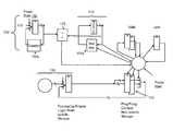
- FIG. 1represents a circuit configured to estimate and/or predict power cycle length in accordance with the invention
- FIG. 2is a flow diagram implementing a process in accordance with the invention.
- FIG. 3is a flow diagram implementing a process in accordance with the invention.
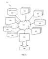
- FIG. 4is a flow diagram of a design process used in semiconductor design, manufacture, and/or test.
- the present inventiongenerally relates to a circuit for estimating and/or predicting power cycle length in low power applications.
- the inventionalso relates to a design structure and method for estimating and/or predicting power cycle length in low power applications. More specifically, the present invention is directed to efficiently harnessing usable power from an intermittent power source by applying power to an application for as long as possible before saving the state (e.g., processed work) in non-volatile memory.
- the non-volatile memoryis assumed to have a significant state saving energy cost and, as such, the present invention will attempt to utilize the volatile memory as long as possible until power loss, at which time the state is saved in the non-volatile memory.
- a checkpoint save into non-volatile memoryis assumed to have a significant energy cost and, by implementing the circuit, method and design structure of the present invention will significantly minimize saves in the non-volatile memory elements.
- the assumptionis that the size of the window of available power is variable over the long term but relatively constant in the short term. This behavior in a power source would be expected in a “heartbeat” situation or where mechanical inertia would come into play (drive shaft coupling, vibration, etc.).
- the present inventionprovides a prediction and/or estimation as to when there will be loss of power and, as such, the appropriate time to save the state in non-volatile memory, thereby decreasing saves in the non-volatile memory and increasing processing efficiency during a power cycle.
- FIG. 1represents a circuit which is designed and configured to implement aspects of the invention.
- the circuitis generally depicted as reference numeral 100 and includes a power start component 110 , which includes a counter 110 a configured to increment the power source in a known manner.
- the circuit 100also includes a threshold register 115 having a counter 115 a .
- the counter 115 ais configured to increment and/or decrement, as appropriate, at every power pulse so that the threshold register 115 can set (and save) the appropriate threshold value (checkpoint).
- the circuit 100 of the inventionis configured to “learn” the time duration of a power “pulse” in a low or no power environment, and set a “saving” checkpoint.
- the circuit 100further includes a determination component 125 .
- the determination component 125determines whether the power cycle is equal to or greater than the threshold value. As the power cycle approaches the threshold value (e.g., equals the threshold value (checkpoint), as determined by the determination component 125 , the circuit will save the state in the non-volatile memory 120 (from volatile storage 130 ). As such, the circuit 100 can use the success/failure of a checkpoint to determine whether more processing or less processing can be done during the available power window before the state is saved in non-volatile memory 120 (at a “PING” and “PONG”).
- the counter 115 awill begin to increment for each power pulse.
- the counter 115 awill have a certain count related to the detected duration of the power cycle.
- the value of the counteris, in turn, provided to the threshold register 115 which sets a threshold value, e.g., a known cycle when power is lost.
- a threshold valuee.g., a known cycle when power is lost.
- the counter 115 acan be incremented and/or decremented to readjust the threshold value, as discussed in more detail below. In this way, the circuit 100 of the invention can “lock” into the length of the power pulse by estimating its length assuming the current length will be similar to the previous length, and adjusting as more is known about the source.
- FIG. 1also shows “Valid” and “Last” flags, each of which is associated with the non-volatile memory 120 .
- the flagsare utilized to indicate a checkpoint, e.g., the location of a successfully saved state in the non-volatile memory 120 and duration of the cycle. For example, at a next power up, the flags will be utilized to determine whether the data in the previous power cycle was saved in the “PING” or “PONG” (i.e., “1” or “0”) of the non-volatile memory 120 .
- the counter 115 acan be incremented, e.g., until a new “last” and “valid” is ascertained, e.g., a new checkpoint is found. If a new checkpoint is found, the system will reset, effectively adjusting the threshold to provide for additional processing time prior to power loss.
- the statecan be retrieved from a prior checkpoint, e.g., “0”, and, in the next power cycle the counter 115 a can be decremented to readjust the power cycle length and hence reset the threshold. In this manner, only one cycle of processing data is lost due to the power loss, and the use of non-volatile memory can be minimized.
- FIGS. 2 and 3are flow diagrams showing processing steps of embodiments of the invention.
- FIGS. 2 and 3may equally represent a high-level block diagram of components of the invention implementing the steps thereof.
- the steps of FIGS. 2 and 3may be implemented on computer program code in combination with the appropriate hardware (e.g., circuit).
- This computer program codemay be stored on storage media such as read-only memory (ROM) or random access memory (RAM).
- ROMread-only memory
- RAMrandom access memory
- the inventioncan take the form of an entirely hardware embodiment (e.g., the circuit of FIG. 1 ) or an embodiment containing both hardware and software elements.
- the followingis pseudo code to adjust a processing period to power event length, as shown in FIG. 2 .
- a power cyclebegins.
- a determinationis made as to whether the last cycle (e.g., “PONG”) was successfully completed during the previous power cycle, e.g., valid (“0” represents a non-valid). If the last cycle was valid, the threshold is incremented at step 210 . If the last cycle was not valid, at step 215 , the system will back up to the previous checkpoint (e.g., “PING”).
- a determinationis made as to whether the previous checkpoint (e.g., “PING”) is valid. If the previous checkpoint (e.g., “PING”) is not valid, at step 225 , the state is lost and the system will reset, at step 225 .
- the thresholdis decreased at step 230 in order to ensure that the state can be properly saved at a next power loss.
- a new assignmentis reset, e.g., a new checkpoint set, at step 235 .
- the contextpreviously saved data
- processingcontinues during the current power cycle. This can be done by utilizing the “last” and “valid” flags.
- the last cycleis complemented (e.g., the pointer is flipped from its current state to another state, “1” to “0” or vice versa).
- the counteris assigned to “0”, e.g., initialized for the next power cycle.
- the datais processed during the power cycle.
- the counteris incremented during the power cycle.
- a determinationis made as to whether the count is greater than the threshold. If the count is less than the threshold, processing continues at step 255 ; however, if the counter is greater than the threshold, the context is saved at step 270 .
- the last checkpointis validated.
- FIG. 3shows an extension to the processing steps in accordance with the invention.
- FIG. 3shows an extension of the logic of FIG. 2 continuing to process data until power failure, periodically checkpointing in a ping-pong fashion.
- the “threshold” valueis increased as processing continues. When power is lost and restored the “threshold” is the value of the number of processing cycles successfully saved in the last checkpoint save.
- the last valid contextis restored at start up.
- the systemwill backup to the previous checkpoint (e.g., “PING”).
- the counteris assigned to “0”, e.g., initialized for the next power cycle.
- the datais processed during the power cycle.
- the counteris incremented during the power cycle.
- a determinationis made as to whether the count is greater than the threshold. If the count is less than the threshold, processing continues at step 325 ; however, if the counter is greater than the threshold, the last context is saved at step 330 .
- the systemassigns the valid save to “1” (“PONG”).
- the last cycleis complemented (e.g., the pointer is flipped from its current state to another state, “1” to “0” or vice versa).
- a new assignmentis reset.
- the thresholdis increased.
- the datais processed during the power cycle.
- the counteris incremented during the power cycle.
- a determinationis made as to whether the count is greater than the threshold. If the count is less than the threshold, processing continues at step 350 ; however, if the counter is greater than the threshold, the context is saved at step 370 .
- a new assignmentis reset, and the process returns to step 340 .
- the processescan set a flag that states that a failure has occurred recently, where recently is defined as a time period measured by current time, e.g., failure latch time. After the current time has moved beyond the set time period the recent error flag is reset. During the time that recently failed the count threshold counter is not incremented. When the recently failed bit is reset then the threshold count counter is allowed to increment.
- FIG. 4shows a block diagram of an exemplary design flow 900 used for example, in semiconductor design, manufacturing, and/or test.
- Design flow 900may vary depending on the type of IC being designed.
- a design flow 900 for building an application specific IC (ASIC)may differ from a design flow 900 for designing a standard component.
- Design structure 920is preferably an input to a design process 910 and may come from an IP provider, a core developer, or other design company or may be generated by the operator of the design flow, or from other sources.
- Design structure 920comprises an embodiment of the invention as shown in, for example, FIG. 1 in the form of schematics or HDL, a hardware-description language (e.g., Verilog, VHDL, C, etc.).
- Design structure 920may be contained on one or more machine readable medium.
- design structure 920may be a text file or a graphical representation of an embodiment of the invention as shown in, for example, FIG. 1 .
- Design process 910preferably synthesizes (or translates) an embodiment of the invention as shown in, for example, FIG. 1 into a netlist 980 , where netlist 980 is, for example, a list of wires, transistors, logic gates, control circuits, I/O, models, etc. that describes the connections to other elements and circuits in an integrated circuit design and recorded on at least one of machine readable medium.
- the mediummay be a CD, a compact flash, other flash memory, a packet of data to be sent via the Internet, or other networking suitable means.
- the synthesismay be an iterative process in which netlist 980 is resynthesized one or more times depending on design specifications and parameters for the circuit.
- Design process 910may include using a variety of inputs; for example, inputs from library elements 930 which may house a set of commonly used elements, circuits, and devices, including models, layouts, and symbolic representations, for a given manufacturing technology (e.g., different technology nodes, 32 nm, 45 nm, 90 nm, etc.), design specifications 940 , characterization data 950 , verification data 960 , design rules 970 , and test data files 985 (which may include test patterns and other testing information). Design process 910 may further include, for example, standard circuit design processes such as timing analysis, verification, design rule checking, place and route operations, etc.
- standard circuit design processessuch as timing analysis, verification, design rule checking, place and route operations, etc.
- Design process 910preferably translates an embodiment of the invention as shown in, for example, FIG. 1 , along with any additional integrated circuit design or data (if applicable), into a second design structure 990 .
- Design structure 990resides on a storage medium in a data format used for the exchange of layout data of integrated circuits and/or symbolic data format (e.g. information stored in a GDSII (GDS2), GL1, OASIS, map files, or any other suitable format for storing such design structures).
- GDSIIGDS2
- GL1GL1, OASIS, map files, or any other suitable format for storing such design structures.
- Design structure 990may comprise information such as, for example, symbolic data, map files, test data files, design content files, manufacturing data, layout parameters, wires, levels of metal, vias, shapes, data for routing through the manufacturing line, and any other data required by a semiconductor manufacturer to produce an embodiment of the invention as shown in, for example, FIG. 1 .
- Design structure 990may then proceed to a stage 995 where, for example, design structure 990 : proceeds to tape-out, is released to manufacturing, is released to a mask house, is sent to another design house, is sent back to the customer, etc.
Landscapes
- Engineering & Computer Science (AREA)
- Power Engineering (AREA)
- Design And Manufacture Of Integrated Circuits (AREA)
Abstract
Description
| If Valid(Last) = 0 | ; If last processing step did not complete |
| successfully | |
| THEN | ; THEN |
| Last <= NOT Last | ; Back up to previous checkpoint |
| DECREASE COUNT | ; and decrease processing time (power even |
| getting shorter) | |
| IF Valid(Last) = 0 | ; IF previous checkpoint also invalid |
| THEN *SYSTEM RESET* | ; THEN we've lost state and must reset system |
| END IF |
| ELSE | ; ELSE (last processing step completed) |
| INCREASE COUNT | ; Increase processing time threshold |
| END IF | |
| RESTORE Context(Last) | ; Restore context from last successful checkpoint |
| Last<=NOT Last | ; Flip pointer to next checkpoint storage |
| Count <= 0 | ; Initialize processing timer |
| While count < threshold | ; Do |
| PROCESS DATA | ; Processing |
| INCREMENT COUNT | ; increment count |
| END WHILE | ; until threshold exceeded |
| SAVE CONTEXT(Last) | ; checkpoint progress in memory pointed to by |
| last | |
| SAVE Valid(Last) | ; Validate last checkpoint |
| If Valid(Last) = 0 | ; If last processing step did not complete |
| successfully | |
| THEN | ; THEN |
| Last <= NOT Last | ; Back up to previous checkpoint |
| DECREASE threshold | ; and decrease processing time (power even |
| getting shorter) Threshold is the duration |
| IF Valid(Last) = 0 | ; IF previous checkpoint also invalid |
| THEN *SYSTEM RESET* | ; THEN we've lost state and must reset system |
| END IF |
| ELSE | ; ELSE (last processing step completed) |
| INCREASE threshold | ; Increase processing time threshold |
| END IF |
| RESTORE Context(Last) | ; Restore context from last successful checkpoint |
| Last<=NOT Last | ; Flip pointer to next checkpoint storage |
| Count <= 0 | ; Initialize processing timer |
| WHILE Count < Threshold ; Do |
| PROCESS DATA | ; Processing |
| INCREMENT COUNT | ; increment count |
| END WHILE | ; until threshold exceeded |
| SAVE CONTEXT(Last) | ; checkpoint progress in memory pointed to by last |
| SAVE Valid(Last) | ; Validate last checkpoint |
| Do Forever | ; While power exists Do: |
| Last<=NOT Last | ; Pingpong context memory |
| Valid(Last)<=‘0’ | ; Clear context valid flag |
| INCREASE Threshold | ; Increase save threshold count |
| WHILE Count < Threshold | ; Do Count to Threshold |
| PROCESS DATA | ; Do the data |
| INCREMENT COUNT | ; Increment save counter |
| END WHILE | ; |
| SAVE CONTEXT(Last) | ; Save context checkpoint |
| Valid(Last)<=‘1’ | ; Set context checkpoint valid flag |
| END DO | |
Claims (20)
Priority Applications (1)
| Application Number | Priority Date | Filing Date | Title |
|---|---|---|---|
| US12/109,379US7903493B2 (en) | 2008-04-25 | 2008-04-25 | Design structure for estimating and/or predicting power cycle length, method of estimating and/or predicting power cycle length and circuit thereof |
Applications Claiming Priority (1)
| Application Number | Priority Date | Filing Date | Title |
|---|---|---|---|
| US12/109,379US7903493B2 (en) | 2008-04-25 | 2008-04-25 | Design structure for estimating and/or predicting power cycle length, method of estimating and/or predicting power cycle length and circuit thereof |
Publications (2)
| Publication Number | Publication Date |
|---|---|
| US20090268541A1 US20090268541A1 (en) | 2009-10-29 |
| US7903493B2true US7903493B2 (en) | 2011-03-08 |
Family
ID=41214892
Family Applications (1)
| Application Number | Title | Priority Date | Filing Date |
|---|---|---|---|
| US12/109,379Expired - Fee RelatedUS7903493B2 (en) | 2008-04-25 | 2008-04-25 | Design structure for estimating and/or predicting power cycle length, method of estimating and/or predicting power cycle length and circuit thereof |
Country Status (1)
| Country | Link |
|---|---|
| US (1) | US7903493B2 (en) |
Families Citing this family (2)
| Publication number | Priority date | Publication date | Assignee | Title |
|---|---|---|---|---|
| US10061376B2 (en)* | 2015-06-26 | 2018-08-28 | Intel Corporation | Opportunistic power management for managing intermittent power available to data processing device having semi-non-volatile memory or non-volatile memory |
| FR3114668A1 (en)* | 2020-09-30 | 2022-04-01 | Stmicroelectronics S.R.L. | System on a chip for cryptography applications including a monotonic counter and associated implementation method |
Citations (8)
| Publication number | Priority date | Publication date | Assignee | Title |
|---|---|---|---|---|
| US20040176878A1 (en) | 2003-03-07 | 2004-09-09 | Orion Electric Company Ltd. | Electric device |
| US20040219740A1 (en) | 2003-03-17 | 2004-11-04 | Toshiyuki Nishihara | Information processing apparatus and semiconductor memory |
| US20050120358A1 (en)* | 2002-11-21 | 2005-06-02 | Fujitsu Limited | Event notifying method, device and processor system |
| US20050125702A1 (en)* | 2003-12-03 | 2005-06-09 | International Business Machines Corporation | Method and system for power management including device controller-based device use evaluation and power-state control |
| US20050138442A1 (en)* | 2003-12-22 | 2005-06-23 | International Business Machines Corporation | Method and system for energy management in a simultaneous multi-threaded (SMT) processing system including per-thread device usage monitoring |
| US20060259791A1 (en)* | 2005-05-10 | 2006-11-16 | Dockser Kenneth A | Idle-element prediction circuitry and anti-thrashing logic |
| US20070011475A1 (en) | 2004-02-12 | 2007-01-11 | Microsoft Corporation | Intermittent computing |
| US20090109741A1 (en)* | 2007-10-26 | 2009-04-30 | International Business Machines Corporation | Determining history state of data in data retaining device based on state of partially depleted silicon-on-insulator |
- 2008
- 2008-04-25USUS12/109,379patent/US7903493B2/ennot_activeExpired - Fee Related
Patent Citations (9)
| Publication number | Priority date | Publication date | Assignee | Title |
|---|---|---|---|---|
| US20050120358A1 (en)* | 2002-11-21 | 2005-06-02 | Fujitsu Limited | Event notifying method, device and processor system |
| US20040176878A1 (en) | 2003-03-07 | 2004-09-09 | Orion Electric Company Ltd. | Electric device |
| US20040219740A1 (en) | 2003-03-17 | 2004-11-04 | Toshiyuki Nishihara | Information processing apparatus and semiconductor memory |
| US6967891B2 (en) | 2003-03-17 | 2005-11-22 | Sony Corporation | Information processing apparatus and semiconductor memory |
| US20050125702A1 (en)* | 2003-12-03 | 2005-06-09 | International Business Machines Corporation | Method and system for power management including device controller-based device use evaluation and power-state control |
| US20050138442A1 (en)* | 2003-12-22 | 2005-06-23 | International Business Machines Corporation | Method and system for energy management in a simultaneous multi-threaded (SMT) processing system including per-thread device usage monitoring |
| US20070011475A1 (en) | 2004-02-12 | 2007-01-11 | Microsoft Corporation | Intermittent computing |
| US20060259791A1 (en)* | 2005-05-10 | 2006-11-16 | Dockser Kenneth A | Idle-element prediction circuitry and anti-thrashing logic |
| US20090109741A1 (en)* | 2007-10-26 | 2009-04-30 | International Business Machines Corporation | Determining history state of data in data retaining device based on state of partially depleted silicon-on-insulator |
Also Published As
| Publication number | Publication date |
|---|---|
| US20090268541A1 (en) | 2009-10-29 |
Similar Documents
| Publication | Publication Date | Title |
|---|---|---|
| US10061512B2 (en) | Data storage device and data writing method thereof | |
| JP5608139B2 (en) | Handling errors during device boot-up from non-volatile memory | |
| US20180114570A1 (en) | Data Storage Device and Data Writing Method Thereof | |
| CN104335285B (en) | System and method for searching content addressable memory, circuit and memory operation method | |
| Georgakos et al. | Reliability challenges for electric vehicles: from devices to architecture and systems software | |
| CN103988182B (en) | Processed using the dynamic error of parity check sum redundant row | |
| TW200928734A (en) | System, method and a computer program product for writing data to different storage devices based on write frequency | |
| US20180101303A1 (en) | Data Storage Device and Data Writing Method Thereof | |
| CN102609276A (en) | Method for pre-loading common application program and electronic device thereof | |
| US20120317343A1 (en) | Data processing apparatus | |
| US7903493B2 (en) | Design structure for estimating and/or predicting power cycle length, method of estimating and/or predicting power cycle length and circuit thereof | |
| GB2554942A (en) | Verifying firmware binary images using a hardware design and formal assertions | |
| Agbo et al. | Comparative BTI analysis for various sense amplifier designs | |
| US10678974B2 (en) | System and method for generation of an integrated circuit design | |
| US9996458B1 (en) | Memory sector retirement in a non-volatile memory | |
| US8587981B2 (en) | Memory, computing system and method for checkpointing | |
| EP1990728A1 (en) | Degeneration controller and degeneration control program | |
| TWI607442B (en) | Methods,systems and computer readable media for adaptively programming or erasing flash memory blocks | |
| RU2010126180A (en) | METHOD FOR MASKING THE TRANSITION TO THE END OF THE PERIOD OF ELECTRONIC DEVICE SERVICE AND THE DEVICE CONTAINING AN APPROPRIATE CONTROL MODULE | |
| US9704598B2 (en) | Use of in-field programmable fuses in the PCH dye | |
| CN110908825B (en) | Data reading method and device, storage equipment and storage medium | |
| JP6785007B2 (en) | Information processing equipment, information processing methods and programs | |
| JP2008059743A (en) | Flash memory device having multi-page copyback function and block replacement method thereof | |
| Oboril et al. | Cross-Layer Approaches for an Aging-Aware Design Space Exploration for Microprocessors. | |
| Aymerich et al. | New reliability mechanisms in memory design for sub-22nm technologies |
Legal Events
| Date | Code | Title | Description |
|---|---|---|---|
| AS | Assignment | Owner name:INTERNATIONAL BUSINESS MACHINES CORPORATION, NEW Y Free format text:ASSIGNMENT OF ASSIGNORS INTEREST;ASSIGNORS:GOODNOW, KENNETH J.;OGILVIE, CLARENCE R.;SHARMA, NITIN;AND OTHERS;REEL/FRAME:020854/0168;SIGNING DATES FROM 20080403 TO 20080421 Owner name:INTERNATIONAL BUSINESS MACHINES CORPORATION, NEW Y Free format text:ASSIGNMENT OF ASSIGNORS INTEREST;ASSIGNORS:GOODNOW, KENNETH J.;OGILVIE, CLARENCE R.;SHARMA, NITIN;AND OTHERS;SIGNING DATES FROM 20080403 TO 20080421;REEL/FRAME:020854/0168 | |
| STCF | Information on status: patent grant | Free format text:PATENTED CASE | |
| REMI | Maintenance fee reminder mailed | ||
| FPAY | Fee payment | Year of fee payment:4 | |
| SULP | Surcharge for late payment | ||
| AS | Assignment | Owner name:GLOBALFOUNDRIES U.S. 2 LLC, NEW YORK Free format text:ASSIGNMENT OF ASSIGNORS INTEREST;ASSIGNOR:INTERNATIONAL BUSINESS MACHINES CORPORATION;REEL/FRAME:036550/0001 Effective date:20150629 | |
| AS | Assignment | Owner name:GLOBALFOUNDRIES INC., CAYMAN ISLANDS Free format text:ASSIGNMENT OF ASSIGNORS INTEREST;ASSIGNORS:GLOBALFOUNDRIES U.S. 2 LLC;GLOBALFOUNDRIES U.S. INC.;REEL/FRAME:036779/0001 Effective date:20150910 | |
| MAFP | Maintenance fee payment | Free format text:PAYMENT OF MAINTENANCE FEE, 8TH YEAR, LARGE ENTITY (ORIGINAL EVENT CODE: M1552); ENTITY STATUS OF PATENT OWNER: LARGE ENTITY Year of fee payment:8 | |
| AS | Assignment | Owner name:WILMINGTON TRUST, NATIONAL ASSOCIATION, DELAWARE Free format text:SECURITY AGREEMENT;ASSIGNOR:GLOBALFOUNDRIES INC.;REEL/FRAME:049490/0001 Effective date:20181127 | |
| AS | Assignment | Owner name:GLOBALFOUNDRIES U.S. INC., CALIFORNIA Free format text:ASSIGNMENT OF ASSIGNORS INTEREST;ASSIGNOR:GLOBALFOUNDRIES INC.;REEL/FRAME:050122/0001 Effective date:20190821 | |
| AS | Assignment | Owner name:MARVELL INTERNATIONAL LTD., BERMUDA Free format text:ASSIGNMENT OF ASSIGNORS INTEREST;ASSIGNOR:GLOBALFOUNDRIES U.S. INC.;REEL/FRAME:051070/0625 Effective date:20191105 | |
| AS | Assignment | Owner name:CAVIUM INTERNATIONAL, CAYMAN ISLANDS Free format text:ASSIGNMENT OF ASSIGNORS INTEREST;ASSIGNOR:MARVELL INTERNATIONAL LTD.;REEL/FRAME:052918/0001 Effective date:20191231 | |
| AS | Assignment | Owner name:MARVELL ASIA PTE, LTD., SINGAPORE Free format text:ASSIGNMENT OF ASSIGNORS INTEREST;ASSIGNOR:CAVIUM INTERNATIONAL;REEL/FRAME:053475/0001 Effective date:20191231 | |
| AS | Assignment | Owner name:GLOBALFOUNDRIES INC., CAYMAN ISLANDS Free format text:RELEASE BY SECURED PARTY;ASSIGNOR:WILMINGTON TRUST, NATIONAL ASSOCIATION;REEL/FRAME:054636/0001 Effective date:20201117 | |
| FEPP | Fee payment procedure | Free format text:MAINTENANCE FEE REMINDER MAILED (ORIGINAL EVENT CODE: REM.); ENTITY STATUS OF PATENT OWNER: LARGE ENTITY | |
| LAPS | Lapse for failure to pay maintenance fees | Free format text:PATENT EXPIRED FOR FAILURE TO PAY MAINTENANCE FEES (ORIGINAL EVENT CODE: EXP.); ENTITY STATUS OF PATENT OWNER: LARGE ENTITY | |
| STCH | Information on status: patent discontinuation | Free format text:PATENT EXPIRED DUE TO NONPAYMENT OF MAINTENANCE FEES UNDER 37 CFR 1.362 | |
| FP | Lapsed due to failure to pay maintenance fee | Effective date:20230308 |