US7902771B2 - Time division modulation with average current regulation for independent control of arrays of light emitting diodes - Google Patents
Time division modulation with average current regulation for independent control of arrays of light emitting diodesDownload PDFInfo
- Publication number
- US7902771B2 US7902771B2US11/603,689US60368906AUS7902771B2US 7902771 B2US7902771 B2US 7902771B2US 60368906 AUS60368906 AUS 60368906AUS 7902771 B2US7902771 B2US 7902771B2
- Authority
- US
- United States
- Prior art keywords
- series
- light
- emitting diodes
- current
- multiplexer
- Prior art date
- Legal status (The legal status is an assumption and is not a legal conclusion. Google has not performed a legal analysis and makes no representation as to the accuracy of the status listed.)
- Active, expires
Links
- 238000003491arrayMethods0.000titledescription7
- 239000003990capacitorSubstances0.000claimsdescription28
- 230000004044responseEffects0.000claimsdescription12
- 238000000034methodMethods0.000abstractdescription44
- 238000012358sourcingMethods0.000abstract1
- 238000010586diagramMethods0.000description21
- 238000004519manufacturing processMethods0.000description12
- 238000005286illuminationMethods0.000description8
- 238000012544monitoring processMethods0.000description7
- 230000003287optical effectEffects0.000description7
- 238000004891communicationMethods0.000description6
- 239000000872bufferSubstances0.000description5
- 230000008859changeEffects0.000description5
- 230000006870functionEffects0.000description5
- 230000008878couplingEffects0.000description4
- 238000010168coupling processMethods0.000description4
- 238000005859coupling reactionMethods0.000description4
- 238000013500data storageMethods0.000description4
- 239000000463materialSubstances0.000description4
- 238000012986modificationMethods0.000description4
- 230000004048modificationEffects0.000description4
- 230000008569processEffects0.000description4
- 238000004088simulationMethods0.000description4
- 238000004804windingMethods0.000description4
- 238000013459approachMethods0.000description3
- 238000006243chemical reactionMethods0.000description3
- 235000019800disodium phosphateNutrition0.000description3
- 230000000694effectsEffects0.000description3
- 238000005259measurementMethods0.000description3
- 230000003044adaptive effectEffects0.000description2
- 238000012937correctionMethods0.000description2
- 238000009795derivationMethods0.000description2
- 238000013461designMethods0.000description2
- 238000001514detection methodMethods0.000description2
- 238000006467substitution reactionMethods0.000description2
- 230000001133accelerationEffects0.000description1
- 230000003213activating effectEffects0.000description1
- 230000004913activationEffects0.000description1
- 230000006978adaptationEffects0.000description1
- 230000000712assemblyEffects0.000description1
- 238000000429assemblyMethods0.000description1
- 230000006399behaviorEffects0.000description1
- 230000005540biological transmissionEffects0.000description1
- 230000000903blocking effectEffects0.000description1
- 238000010276constructionMethods0.000description1
- 238000006073displacement reactionMethods0.000description1
- 230000007613environmental effectEffects0.000description1
- 238000012545processingMethods0.000description1
- 239000004065semiconductorSubstances0.000description1
- 238000000926separation methodMethods0.000description1
- 230000001360synchronised effectEffects0.000description1
- 238000012546transferMethods0.000description1
- 230000001131transforming effectEffects0.000description1
- 230000007723transport mechanismEffects0.000description1
Images


Classifications
- H—ELECTRICITY
- H05—ELECTRIC TECHNIQUES NOT OTHERWISE PROVIDED FOR
- H05B—ELECTRIC HEATING; ELECTRIC LIGHT SOURCES NOT OTHERWISE PROVIDED FOR; CIRCUIT ARRANGEMENTS FOR ELECTRIC LIGHT SOURCES, IN GENERAL
- H05B45/00—Circuit arrangements for operating light-emitting diodes [LED]
- H05B45/30—Driver circuits
- H05B45/37—Converter circuits
- H05B45/3725—Switched mode power supply [SMPS]
- H05B45/38—Switched mode power supply [SMPS] using boost topology
- H—ELECTRICITY
- H05—ELECTRIC TECHNIQUES NOT OTHERWISE PROVIDED FOR
- H05B—ELECTRIC HEATING; ELECTRIC LIGHT SOURCES NOT OTHERWISE PROVIDED FOR; CIRCUIT ARRANGEMENTS FOR ELECTRIC LIGHT SOURCES, IN GENERAL
- H05B45/00—Circuit arrangements for operating light-emitting diodes [LED]
- H05B45/20—Controlling the colour of the light
- H05B45/22—Controlling the colour of the light using optical feedback
- H—ELECTRICITY
- H05—ELECTRIC TECHNIQUES NOT OTHERWISE PROVIDED FOR
- H05B—ELECTRIC HEATING; ELECTRIC LIGHT SOURCES NOT OTHERWISE PROVIDED FOR; CIRCUIT ARRANGEMENTS FOR ELECTRIC LIGHT SOURCES, IN GENERAL
- H05B45/00—Circuit arrangements for operating light-emitting diodes [LED]
- H05B45/20—Controlling the colour of the light
- H05B45/24—Controlling the colour of the light using electrical feedback from LEDs or from LED modules
- H—ELECTRICITY
- H05—ELECTRIC TECHNIQUES NOT OTHERWISE PROVIDED FOR
- H05B—ELECTRIC HEATING; ELECTRIC LIGHT SOURCES NOT OTHERWISE PROVIDED FOR; CIRCUIT ARRANGEMENTS FOR ELECTRIC LIGHT SOURCES, IN GENERAL
- H05B45/00—Circuit arrangements for operating light-emitting diodes [LED]
- H05B45/40—Details of LED load circuits
- H05B45/44—Details of LED load circuits with an active control inside an LED matrix
- H05B45/46—Details of LED load circuits with an active control inside an LED matrix having LEDs disposed in parallel lines
- H—ELECTRICITY
- H05—ELECTRIC TECHNIQUES NOT OTHERWISE PROVIDED FOR
- H05B—ELECTRIC HEATING; ELECTRIC LIGHT SOURCES NOT OTHERWISE PROVIDED FOR; CIRCUIT ARRANGEMENTS FOR ELECTRIC LIGHT SOURCES, IN GENERAL
- H05B45/00—Circuit arrangements for operating light-emitting diodes [LED]
- H05B45/40—Details of LED load circuits
- H05B45/44—Details of LED load circuits with an active control inside an LED matrix
- H05B45/48—Details of LED load circuits with an active control inside an LED matrix having LEDs organised in strings and incorporating parallel shunting devices
- H—ELECTRICITY
- H05—ELECTRIC TECHNIQUES NOT OTHERWISE PROVIDED FOR
- H05B—ELECTRIC HEATING; ELECTRIC LIGHT SOURCES NOT OTHERWISE PROVIDED FOR; CIRCUIT ARRANGEMENTS FOR ELECTRIC LIGHT SOURCES, IN GENERAL
- H05B45/00—Circuit arrangements for operating light-emitting diodes [LED]
- H05B45/30—Driver circuits
- H05B45/37—Converter circuits
- H05B45/3725—Switched mode power supply [SMPS]
- Y—GENERAL TAGGING OF NEW TECHNOLOGICAL DEVELOPMENTS; GENERAL TAGGING OF CROSS-SECTIONAL TECHNOLOGIES SPANNING OVER SEVERAL SECTIONS OF THE IPC; TECHNICAL SUBJECTS COVERED BY FORMER USPC CROSS-REFERENCE ART COLLECTIONS [XRACs] AND DIGESTS
- Y02—TECHNOLOGIES OR APPLICATIONS FOR MITIGATION OR ADAPTATION AGAINST CLIMATE CHANGE
- Y02B—CLIMATE CHANGE MITIGATION TECHNOLOGIES RELATED TO BUILDINGS, e.g. HOUSING, HOUSE APPLIANCES OR RELATED END-USER APPLICATIONS
- Y02B20/00—Energy efficient lighting technologies, e.g. halogen lamps or gas discharge lamps
- Y02B20/30—Semiconductor lamps, e.g. solid state lamps [SSL] light emitting diodes [LED] or organic LED [OLED]
Definitions
- the present inventionin general is related to converters and regulators used for driving and controlling arrays of light emitting diodes and, in particular, is related to an apparatus, system and method for time division modulation with average current regulation for independent control of arrays of light emitting diodes.
- LED arraysare utilized for a wide variety of applications, including for ambient lighting.
- LED arraystypically utilize a combination of red, green and blue (“RGB”) LEDs (and, occasionally, amber LEDs), usually as a first series connection (a first “string”) of a plurality of red LEDs, a second series connection (a second string) of a plurality of green LEDs, and a third series connection (a third string) of a plurality of blue LEDs, typically which are referred to as “multistring LEDs”.
- RGBred, green and blue
- LEDsFor driving an array of LEDs, electronic circuits typically employ a converter to transform an AC input voltage (e.g., “AC mains”) and provide a DC voltage source, with a linear regulator then used to regulate LED current.
- AC mainsAC input voltage
- DC voltage sourceDC voltage source
- a linear regulatorthen used to regulate LED current.
- the LEDsmay be controlled by a processor to alter the brightness and/or color of the generated light, such as by using pulse-width modulated (“PWM”) signals.
- PWMpulse-width modulated
- Multistring LED Drivers with PWM regulationare known, e.g., Subramanian Muthu, Frank J. P. Schuurmans, and Michael D. Pashly “Red, Blue, and Green LED for White Light Illumination”, IEEE Journal on Selected Topics in Quantum Electronics , Vol. 8, No. 2, March/April 2002, pp. 333-338.
- Such prior art multistring LED driverstypically require redundant drivers for every LED string.
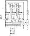
- three separate and independent flyback converters 10operating at a constant switching frequency of 100 kHz drive a corresponding string of an RGB LED light source 15 , with a PWM 20 driving scheme operating at a frequency of 120 Hz.
- Each flyback converter 10contains a current loop to maintain a constant peak current for the PWM pulses.
- the color control systemis implemented in a DSP controller 25 (TMS320F240), which supplies the PWM turn-on and turn off signals for the power supply.
- the circuit 40comprises a power supply source, and a transformer having a primary winding 41 and multiple secondary windings 42 , with each light-emitting-diode string coupled in the circuit to one of the secondary windings.
- a main controller 43is coupled to a first of the light-emitting-diode strings 46 and is configured to control a flow of current to the primary transformer winding 41 .
- the circuitalso comprises an additional plurality of secondary controllers 44 , 45 , each of which is correspondingly coupled to another light-emitting-diode string 47 , 48 to control a flow of current to its corresponding light-emitting-diode string.
- the AS3691includes four independent high precision current sources each capable of sinking 400 mA.
- the operating current per LED channelcan be set via an external resistor, while the LED brightness is controlled by four independent pulse width modulated inputs.
- the AS3691integrates four independent current sinks per chip, enabling it to drive either four white LEDs each sinking 400 mA or a single white LED with up to 1.6 A.
- Another prior art methodutilizes multiple, separate linear regulators, with each regulator separately coupled to an LED string of an LED array.
- an AC-to-DC converterfor transforming AC input voltage into a DC voltage source, is coupled to multiple, dedicated linear regulators, with one regulator coupled to each LED string to regulate the current in that corresponding LED string.
- This approachrepresents a multistage power system with low efficiency of power conversion, in addition to already low efficiency of series pass current regulators, particularly when the DC voltage is constant and does not depend on current.
- This prior art method of multiple and separate linear regulatorsis illustrated in the following U.S. Pat. No. 7,064,498 Light-Emitting Diode Based Products; U.S. Pat. No.
- each LED string of the LED arrayis controlled by a separate current regulator with a processor, to alter the brightness and/or color of the generated light using pulse-width modulated signals.
- an additional, current sink stageis added in series with each LED string current regulator, resulting in a further decrease in efficiency, particularly when the current sink is used to bypass the LED current to ground when the LED should be off.
- This multistage power systemwith dedicated current converters and controllers in each LED channel, in addition to low efficiency, has a large size, many expensive components, and is expensive to manufacture.
- a light emitting diode illumination control systemfor driving a current circuit for energizing one or more LED light sources.
- the systemcomprises a control system including a microprocessor, arranged to control a pulse amplitude modulated (PAM) voltage controlled current circuit, and may employ a monitor for monitoring at least one ambient condition and a microprocessor operable to control the current circuit to response to the monitored conditions.
- PAMpulse amplitude modulated
- a needremains for a multistring LED driver which utilizes a single power converter and controller for an entire LED array and does not utilize these multiple, separate power converters and controllers for each LED string.
- Such a multistring LED drivershould provide for independent current control for each LED string of the array, for corresponding effective color and brightness control.
- such an LED array drivershould provide for local LED regulation, providing local compensation of LED emission due to age and drift of functional parameters, temperature changes of the LED junction, LED production characteristics variation, and variations of devices produced by different manufacturers.
- Such an LED array driveralso should be backwards-compatible with legacy LED control systems.
- the various embodiments of the inventionprovide innumerable advantages for energizing a plurality of series (strings) of LEDs, using a single power converter and controller for an entire LED array, and does not utilize multiple, separate power converters and controllers for each LED string.
- the exemplary embodimentsprovide a multistring LED driver which controls current independently for each series of LEDs of the array, for corresponding effective color and brightness control, among other features.
- the exemplary LED array driversprovide for local LED regulation, achieving local compensation of LED emission due to age and drift of functional parameters, temperature changes of the LED junction, LED production characteristics variation, and variations of devices produced by different manufacturers.
- the exemplary LED array driversare also backwards-compatible with legacy LED control systems.
- Providing such local regulation of LED arraysis a significant advance compared to the prior art use of a central, overall system (or host) computer or microprocessor for certain types of remote regulation.
- the local regulation provided by the present inventionenables a significantly faster response time, without requiring the prior art communication protocols, and further provides a more comprehensive approach for maintaining selected color and brightness levels throughout the life span of the LEDs and corresponding changes in their functional parameters.
- Exemplary embodimentsalso may be implemented using comparatively lower cost controllers. When the exemplary embodiments are further implemented to be backwards-compatible with legacy control systems, the present invention frees the host computer for other tasks and allows such host computers to be utilized for other types of system regulation.
- An exemplary apparatus embodimentfor providing current independently to a series of light emitting diodes of a plurality of series of light-emitting diodes, comprises a power converter, a first multiplexer, and a controller.
- the power converteris couplable to the plurality of series of light-emitting diodes, and the power converter is adapted to generate a current.
- the first multiplexeris also couplable to the plurality of series of light-emitting diodes.
- the controlleris coupled to the power converter and to the first multiplexer, and the controller is adapted to provide for sequential and separate switching of the current through the first multiplexer to each of the series of light-emitting diodes, of the plurality of series of light-emitting diodes, for a corresponding period of time.
- the controlleris further adapted to provide for no switching of current through the first multiplexer to all remaining series of light-emitting diodes while current is switched to a selected series of light-emitting diodes of the plurality of series of light-emitting diodes.
- the controlleris further adapted to determine an average current provided by the power converter as substantially or about equal to a sum of a plurality of corresponding currents through the plurality of series of light-emitting diodes, and to determine a total period for switching current to all of the series of light-emitting diodes of the plurality of series of light-emitting diodes.
- the controllermay also be adapted to determine a corresponding time period for switching current to a selected corresponding series of light-emitting diodes as substantially (or about) equal to a proportion of the total period determined as a ratio of the corresponding current for the selected corresponding series of light-emitting diodes to the average current provided by the power converter.
- An exemplary apparatus embodimentmay further include a memory coupled to the controller, with the memory adapted to store, as a look up table, a plurality of parameters corresponding to the plurality of series of light-emitting diodes.
- the controlleris further adapted to predict an output voltage across a selected series of light-emitting diodes based on the device parameters stored in memory and to revise the predicted output voltage based upon a measured output voltage across a selected series of light-emitting diodes.
- the power convertermay further comprise a first voltage divider, with the controller being further adapted to determine an input voltage across the first voltage divider.
- the power convertermay further comprise a current sensor, with the controller being further adapted to determine a peak input current through the current sensor.
- exemplary embodimentsmay also include a plurality of capacitors, with each capacitor of the plurality of capacitors couplable to a corresponding series of light-emitting diodes of the plurality of series of light-emitting diodes.
- An exemplary apparatus embodimentmay further include a plurality of second voltage dividers, with each second voltage divider couplable in parallel to a corresponding series of light-emitting diodes of the plurality of series of light-emitting diodes, with the controller being further adapted to determine a corresponding output voltage across the corresponding second voltage divider of the plurality of second voltage dividers.
- a second multiplexermay be coupled to the plurality of second voltage dividers and the controller, with the controller being further adapted to control switching of the second multiplexer to a selected second voltage divider of the plurality of second voltage dividers.
- a third multiplexermay be couplable to the plurality of series of light-emitting diodes and coupled to the controller, with the controller being further adapted to control switching of the third multiplexer to a selected series of light-emitting diodes of the plurality of series of light-emitting diodes for measuring a corresponding current through the selected series of light-emitting diodes.
- the controllermay be further adapted to determine the corresponding period of time for switching of current to a selected series of light-emitting diodes based on a comparison of the measured corresponding current to a predetermined current level for the selected series of light-emitting diodes. In other embodiments, the controller may be further adapted to determine the corresponding period of time for switching of current to a selected series of light-emitting diodes based on an integer multiple of a period of switching of the power converter, and may be further adapted to control switching of the first multiplexer to a selected series of light-emitting diodes of the plurality of series of light-emitting diodes when current through the power converter is substantially (or about) zero.
- the controllermay be further adapted, in response to a first input, to adjust an output brightness of the plurality of series of light-emitting diodes by modifying each corresponding period of time of current switching to each of the series of light-emitting diodes.
- the controllermay be further adapted, in response to a second input, to adjust an output color of the plurality of series of light-emitting diodes by modifying at least one corresponding period of time of current switching to at least one of the series of light-emitting diodes of the plurality of series of light-emitting diodes.
- the first multiplexermay comprises a plurality of switches, with each switch of the plurality of switches correspondingly couplable to a first, high side of a corresponding series of light-emitting diodes of the plurality of series of light-emitting diodes, or couplable to a second, low side of a corresponding series of light-emitting diodes of the plurality of series of light-emitting diodes.
- the first multiplexermay comprise a plurality of first switches, with each switch of the plurality of first switches correspondingly couplable to a first, high side of a corresponding series of light-emitting diodes of the plurality of series of light-emitting diodes; and a plurality of second switches, with each switch of the plurality of second switches correspondingly couplable to a second, low side of a corresponding series of light-emitting diodes of the plurality of series of light-emitting diodes.
- the first multiplexermay comprises a plurality of first switches, with each switch of the plurality of first switches correspondingly couplable to a first, high side of a corresponding series of light-emitting diodes of the plurality of series of light-emitting diodes; and a second switch couplable to the plurality of capacitors.
- a lighting systemcomprises a plurality of series of light-emitting diodes, a power converter, a first multiplexer, and a controller.
- the power converteris coupled to the plurality of series of light-emitting diodes and is adapted to generate a current.
- the first multiplexeris coupled to the plurality of series of light-emitting diodes.
- the controlleris coupled to the power converter and to the first multiplexer, and the controller is adapted to provide for sequential and separate switching of the current through the first multiplexer to each of the series of light-emitting diodes, of the plurality of series of light-emitting diodes, for a corresponding period of time.
- the exemplary embodimentsfurther provide a method of selectively and independently providing power to a series of light emitting diodes of a plurality of series of light-emitting diodes.
- the methodcomprises generating an input DC current having a first average level; and sequentially and separately switching the DC current to each of the series of light-emitting diodes, of the plurality of series of light-emitting diodes, for a corresponding period of time.
- the exemplary methodmay further include switching no current to all remaining series of light-emitting diodes while switching the DC current to a selected series of light-emitting diodes of the plurality of series of light-emitting diodes.
- the methodmay also include determining the first average level of DC current as substantially or about equal to a sum of a plurality of corresponding currents through the plurality of series of light-emitting diodes, determining a total period for switching current to all of the series of light-emitting diodes of the plurality of series of light-emitting diodes, and determining a corresponding time period for switching current to a selected corresponding series of light-emitting diodes as substantially or about equal to a proportion of the total period determined as a ratio of the corresponding current for the selected corresponding series of light-emitting diodes to the average current provided by the power converter.
- An exemplary methodmay also include storing, as a look up table, a plurality of parameters corresponding to the plurality of series of light-emitting diodes, and predicting an output voltage across a selected series of light-emitting diodes, of the plurality of series of light-emitting diodes, based on the stored device parameters.
- the exemplary methodmay further include measuring a corresponding output voltage for each series of light emitting diodes of the plurality of series of light-emitting diodes; updating the predicted output voltage across a selected series of light-emitting diodes, of the plurality of series of light-emitting diodes, based on a corresponding measured output voltage; determining an input voltage; determining a peak input DC current; determining a corresponding output voltage for each series of light emitting diodes of the plurality of series of light-emitting diodes; and/or measuring a corresponding current through each series of light-emitting diodes of the plurality of series of light-emitting diodes.
- the methodmay include determining the corresponding period of time for switching of current to a selected series of light-emitting diodes based on a comparison of the measured corresponding current to a predetermined current level for the selected series of light-emitting diodes, and/or determining the corresponding period of time for switching of current to a selected series of light-emitting diodes based on an integer multiple of a period of switching of a power converter.
- the methodmay include switching current to a selected series of light-emitting diodes of the plurality of series of light-emitting diodes when the input DC current is substantially (or about) zero.
- Another exemplary embodimentprovides an apparatus for providing current independently to a series of light emitting diodes of a plurality of series of light-emitting diodes, with the apparatus comprising a power converter, a first multiplexer, a memory, and a controller.
- the power converteris couplable to the plurality of series of light-emitting diodes and is adapted to generate a current.
- the first multiplexeris also couplable to the plurality of series of light-emitting diodes.
- the memoryis adapted to store, as a look up table, a plurality of parameters corresponding to the plurality of series of light-emitting diodes.
- the controlleris coupled to the power converter, to the first multiplexer and to the memory, with the controller being adapted to provide for sequential and separate switching of the current through the first multiplexer to each of the series of light-emitting diodes, of the plurality of series of light-emitting diodes, for a corresponding period of time; the controller further adapted to determine an average current provided by the power converter as substantially or about equal to a sum of a plurality of corresponding currents through the plurality of series of light-emitting diodes, to determine a total period for switching current to all of the series of light-emitting diodes of the plurality of series of light-emitting diodes, and to determine a corresponding time period for switching current to a selected corresponding series of light-emitting diodes as substantially or about equal to a proportion of the total period determined as a ratio of the corresponding current for the selected corresponding series of light-emitting diodes to the average current provided by the power converter.
- FIG. 1(or FIG. 1 ) is a prior art LED array driver.
- FIG. 2(or FIG. 2 ) is a prior art LED array driver.
- FIG. 3(or FIG. 3 ) is a circuit and block diagram illustrating a first exemplary LED array driver circuit in accordance with the teachings of the present invention.
- FIG. 4(or FIG. 4 ) is a timing diagram for a first exemplary LED array driver circuit in accordance with the teachings of the present invention.
- FIG. 5(or FIG. 5 ) is a diagram illustrating continuous current in an inductor in a first exemplary LED array driver circuit in accordance with the teachings of the present invention.
- FIG. 6(or FIG. 6 ) is a diagram illustrating discontinuous current in an inductor in a first exemplary LED array driver circuit in accordance with the teachings of the present invention.
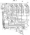
- FIG. 7(or FIG. 7 ) is a circuit and block diagram illustrating a second exemplary LED array driver circuit in accordance with the teachings of the present invention.
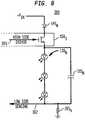
- FIG. 8(or FIG. 8 ) is a circuit diagram illustrating high side driving and low side sensing of a series of LEDs in accordance with the teachings of the present invention.
- FIG. 9(or FIG. 9 ) is a circuit diagram illustrating differential high side sensing and low side driving of a series of LEDs in accordance with the teachings of the present invention.
- FIG. 10(or FIG. 10 ) is a graphical diagram illustrating simulation of a boost LED array driver circuit, for three series of LEDs, in accordance with the teachings of the present invention.
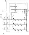
- FIG. 11(or FIG. 11 ) is a circuit diagram illustrating a first configuration of an LED array for independent time division modulation in accordance with the teachings of the present invention.
- FIG. 12(or FIG. 12 ) is a circuit diagram illustrating a second configuration of an LED array for common time division modulation in accordance with the teachings of the present invention.
- FIG. 13(or FIG. 13 ) is a graphical diagram illustrating simulation of LED current in a boost LED array driver circuit, for three LED strings, in accordance with the teachings of the present invention.
- FIG. 14(or FIG. 14 ) is a flow diagram illustrating an exemplary method in accordance with the teachings of the present invention.
- FIG. 3is a circuit and block diagram illustrating a first exemplary LED array driver circuit 100 in accordance with the teachings of the present invention.
- the first exemplary LED array driver circuit 100comprises a (switching) power converter 120 , a parallel array of LEDs 110 , a multiplexer (or other array of power switches) 150 (typically referred to as a first, time-division multiplexer 150 ), a controller 125 , and a memory 175 .
- the exemplary LED array driver circuit 100also comprises one or more sensors 185 , discussed in greater detail below.
- the parallel array of LEDs 110comprises a plurality of series-connected LEDs, i.e., independent series or “strings” of LEDs, illustrated as “N” individual series of LEDs 110 1 , 110 2 , 110 3 , through 110 N .
- Each such series of LEDs 110 1 , 110 2 , 110 3 , through 110 Nmay be referred to equivalently herein as a “channel”, namely, channel one, channel two, channel three, through channel “N”, respectively.
- the “channel” connotationis particularly appropriate for the present invention which, as discussed in greater detail below, provides for independently energizing each series of LEDs 110 1 , 110 2 , 110 3 , through 110 N using time-division modulation (“TDM”, or equivalently, time-division multiplexing).
- TDMtime-division modulation
- Each series of LEDs 110 1 , 110 2 , 110 3 , through 110 Nmay have either the same or different types of LEDs.
- each series of LEDs 110 1 , 110 2 , 110 3 , through 110 Nhave similar characteristics, such as by being fabricated by the same manufacturer and having only production or other manufacturing variations or tolerances.
- LEDs 110 1 , 110 2 , 110 3 , through 110 N having different characteristics, such as be being produced from different manufacturers,may still be modeled appropriately, with corresponding information stored in the memory 175 , and with all such variations considered equivalent and within the scope of the invention.
- various models of LED operation and device characteristicsare created and stored in memory 175 , which may be any type or form of memory, and which further may comprise a look up table structure or a database 180 structure, for example and without limitation.
- Each such channelmay also comprise a corresponding bypass filter capacitor 115 connected in parallel with each series of LEDs 110 1 , 110 2 , 110 3 , through 110 N , illustrated as corresponding capacitors 115 1 , 115 2 , 115 3 , through 115 N .
- a corresponding bypass filter capacitor 115connected in parallel with each series of LEDs 110 1 , 110 2 , 110 3 , through 110 N , illustrated as corresponding capacitors 115 1 , 115 2 , 115 3 , through 115 N .
- the exemplary LED array driver circuit 100further comprises a first, time-division or “energizing” multiplexer (or other array of power switches) 150 , which provides for individually and selectively allowing current to flow through each of the series of LEDs 110 1 , 110 2 , 110 3 , through 110 N , i.e., turning on or off any selected series of LEDs 110 1 , 110 2 , 110 3 , through 110 N .
- a first, time-division or “energizing” multiplexer (or other array of power switches) 150which provides for individually and selectively allowing current to flow through each of the series of LEDs 110 1 , 110 2 , 110 3 , through 110 N , i.e., turning on or off any selected series of LEDs 110 1 , 110 2 , 110 3 , through 110 N .
- the multiplexer 150is configured to allow current through one or more of the series of LEDs 110 1 , 110 2 , 110 3 , through 110 N in any combination, and for any selected duration (time period or time slot), such as one series of LEDs 110 , two series of LEDs 110 , none of the series of LEDs 110 , or all of the series of LEDs 110 , for example.
- the illustrated exemplary power converter 120comprises a DC voltage source 105 , a filter capacitor 135 , an inductor 130 , a switch 140 , a peak current sense resistor (R 1 ) 155 , and the controller 125 .
- the power converter 120may be of any topology which is capable of or adapted to deliver a controlled current level to a load, such as a current having a controlled peak to average current ratio, and may be isolated or non-isolated, including a Buck, Boost, Buck-Boost, or Flyback configuration or topology.
- the DC voltage source 105may be a battery element or an AC/DC converter (not separately illustrated), such as a diode bridge or rectifier, or a more complex, off line switching power supply with power factor correction, for example.
- the DC voltage source 105also may be an AC/DC converter connected to phase modulation AC device (typically wall dimmer) via an impedance matching block, not separately illustrated.
- the power converter 120may operate in a continuous mode of operation (illustrated in FIG. 5 ) or a discontinuous mode of operation (illustrated in FIG. 6 ).
- the controller 125may receive input from a wide variety of sources, including open or closed-loop feedback of various signals and measurements from within the LED array driver circuit 100 , as discussed in greater detail below. Not separately illustrated, the controller 125 may be coupled within a larger system, such as a computer-controlled lighting system in a building, and may interface with other computing elements using a wide variety of data transmission protocols, such as DMX 512, DALI, IC squared, etc.
- the memory 175which may include a data repository (or database) 180 , may be embodied in any number of forms, including within any computer or other machine-readable data storage medium, memory device or other storage or communication device for storage or communication of information, currently known or which becomes available in the future, including, but not limited to, a memory integrated circuit (“IC”), or memory portion of an integrated circuit (such as the resident memory within a controller 125 or processor IC), whether volatile or non-volatile, whether removable or non-removable, including without limitation RAM, FLASH, DRAM, SDRAM, SRAM, MRAM, FeRAM, ROM, EPROM or E 2 PROM, or any other form of memory device, such as a magnetic hard drive, an optical drive, a magnetic disk or tape drive, a hard disk drive, other machine-readable storage or memory media such as a floppy disk, a CDROM, a CD-RW, digital versatile disk (DVD) or other optical memory, or any other type of memory, storage medium, or data storage apparatus or circuit, which is
- Such computer readable mediaincludes any form of communication media which embodies computer readable instructions, data structures, program modules or other data in a data signal or modulated signal, such as an electromagnetic or optical carrier wave or other transport mechanism, including any information delivery media, which may encode data or other information in a signal, wired or wirelessly, including electromagnetic, optical, acoustic, RF or infrared signals, and so on.
- the memory 175is adapted to store various look up tables, parameters, coefficients, other information and data, programs or instructions (of the software of the present invention), and other types of tables such as database tables, discussed below.
- the controller 125may be any type of controller or processor, and may be embodied as one or more controllers 125 , adapted to perform the functionality discussed below.
- a controller 125may include use of a single integrated circuit (“IC”), or may include use of a plurality of integrated circuits or other components connected, arranged or grouped together, such as controllers, microprocessors, digital signal processors (“DSPs”), parallel processors, multiple core processors, custom ICs, application specific integrated circuits (“ASICs”), field programmable gate arrays (“FPGAs”), adaptive computing ICs, associated memory (such as RAM, DRAM and ROM), and other ICs and components.
- DSPsdigital signal processors
- ASICsapplication specific integrated circuits
- FPGAsfield programmable gate arrays
- adaptive computing ICsassociated memory (such as RAM, DRAM and ROM), and other ICs and components.
- controllershould be understood to equivalently mean and include a single IC, or arrangement of custom ICs, ASICs, processors, microprocessors, controllers, FPGAs, adaptive computing ICs, or some other grouping of integrated circuits which perform the functions discussed below, with associated memory, such as microprocessor memory or additional RAM, DRAM, SDRAM, SRAM, MRAM, ROM, FLASH, EPROM or E 2 PROM.
- a controller (or processor)(such as controller 125 ), with its associated memory, may be adapted or configured (via programming, FPGA interconnection, or hard-wiring) to perform the methodology of the invention, as discussed below.
- the methodologymay be programmed and stored, in a controller 125 with its associated memory (and/or memory 175 ) and other equivalent components, as a set of program instructions or other code (or equivalent configuration or other program) for subsequent execution when the processor is operative (i.e., powered on and functioning).
- the controller 125may implemented in whole or part as FPGAs, custom ICs and/or ASICs, the FPGAs, custom ICs or ASICs also may be designed, configured and/or hard-wired to implement the methodology of the invention.
- controller 125may be implemented as an arrangement of controllers, microprocessors, DSPs and/or ASICs, collectively referred to as a “controller”, which are respectively programmed, designed, adapted or configured to implement the methodology of the invention, in conjunction with a memory 175 .
- the controller 125is programmed, using software and data structures of the invention, for example, to perform the methodology of the present invention.
- the system and method of the present inventionmay be embodied as software which provides such programming or other instructions, such as a set of instructions and/or metadata embodied within a computer readable medium, discussed above.
- metadatamay also be utilized to define the various data structures of a look up table or a database 180 .
- Such softwaremay be in the form of source or object code, by way of example and without limitation. Source code further may be compiled into some form of instructions or object code (including assembly language instructions or configuration information).
- the software, source code or metadata of the present inventionmay be embodied as any type of code, such as C, C++, SystemC, LISA, XML, Java, Brew, SQL and its variations (e.g., SQL 99 or proprietary versions of SQL), DB2, Oracle, or any other type of programming language which performs the functionality discussed herein, including various hardware definition or hardware modeling languages (e.g., Verilog, VHDL, RTL) and resulting database files (e.g., GDSII).
- codesuch as C, C++, SystemC, LISA, XML, Java, Brew, SQL and its variations (e.g., SQL 99 or proprietary versions of SQL), DB2, Oracle, or any other type of programming language which performs the functionality discussed herein, including various hardware definition or hardware modeling languages (e.g., Verilog, VHDL, RTL) and resulting database files (e.g., GDSII).
- a “construct”, “program construct”, “software construct” or “software”, as used equivalently herein,means and refers to any programming language, of any kind, with any syntax or signatures, which provides or can be interpreted to provide the associated functionality or methodology specified (when instantiated or loaded into a processor or computer and executed, including the controller 125 , for example).
- the software, metadata, or other source code of the present invention and any resulting bit filemay be embodied within any tangible storage medium, such as any of the computer or other machine-readable data storage media, as computer-readable instructions, data structures, program modules or other data, such as discussed above with respect to the memory 175 , e.g., a floppy disk, a CDROM, a CD-RW, a DVD, a magnetic hard drive, an optical drive, or any other type of data storage apparatus or medium, as mentioned above.
- FIG. 4is a timing diagram for a first exemplary LED array driver circuit 100 , and illustrates the time division modulation for current regulation in accordance with the teachings of the present invention.
- each series of LEDs 110 1 , 110 2 , 110 3 , through 110 Nwill be provided with a selected and independent current level, through control (by controller 125 ) of the switching state of each channel (via multiplexer 150 ), for a selected time period (or duration), illustrated as first time period T Q1 for series of LEDs 110 1 , second time period T Q2 for series of LEDs 110 2 , third time period T Q3 for series of LEDs 110 3 , fourth time period T Q4 for series of LEDs 110 4 , through “N th ” time period T QN for series of LEDs 110 N .
- the total time period for providing current to all of the series of LEDs 110 1 , 110 2 , 110 3 , through 110 Nis referred to herein as “T C ”.
- T CThe total time period for providing current to all of the series of LEDs 110 1 , 110 2 , 110 3 , through 110 N is referred to herein as “T C ”.
- Each of these time periodsmay be selected and varied during operation of the LED array driver circuit 100 , providing time division modulation.
- Each energizing time periodmay be provided in any order or combination; for example, series of LEDs 110 3 may be provided with current for third time period T Q3 , followed by series of LEDs 110 2 being provided with current for second time period T Q4 , followed by both series of LEDs 110 1 and series of LEDs 110 N being provided with selected current levels for corresponding first and N th time periods T Q1 and T QN , respectively.
- each series of LEDs 110 1 , 110 2 , 110 3 , through 110 Nmay be selected and varied during operation of the LED array driver circuit 100 , as discussed in greater detail below, additionally providing for the average current regulation of the present invention.
- the intervals or time periods (illustrated as T A , T B , and T C ) between successive energizing time periods T Q1 , T Q2 through T QNmay also be selected and varied, depending upon the selected embodiment.
- the average DC current in each channel(series of LEDs 110 1 , 110 2 , 110 3 , through 110 N ) as I Ci , (i.e., average DC current I CI for series of LEDs 110 1 , average DC current I C2 for series of LEDs 110 2 , average DC current I C3 for series of LEDs 110 3 , through average DC current I CN for series of LEDs 110 N ), then the average current I C provided by the current source (in this case, power converter 120 ) is equal to
- T QiI ci ⁇ T c I c .
- T Qim i T, where m i is the number of cycles of the power converter 120 per channel (series of LEDs 110 ).
- the period of time T c and the cycle time Tis selected such that m i is an interger.
- I c1500 mA
- I c2520 mA
- I c3480 mA
- I c 500+520+4801500 mA.
- the power converter 120will supply to each channel a current of 1500 mA for the run times
- An exemplary boost convertermay be utilized to generate the required average current I c in every channel.
- I crequired average current
- those skilled in the artmay derive similar equations for other power converter (or current source) topologies.
- CCMcontinuous conduction mode
- I cI p ⁇ ⁇ 1 ⁇ i + I p ⁇ ⁇ 2 ⁇ i 2 ⁇ t r ⁇ ⁇ 1 T , where
- a iI p ⁇ ⁇ 2 ⁇ i I p ⁇ ⁇ 1 ⁇ i , namely, the ratio of the second peak current to the first peak current for a selected ith channel, and
- b it ri T , namely, the ratio of the switch 140 reset time (i.e., off or open time) to the total cycle time, resulting in a first peak current for an ith channel of:
- I p ⁇ ⁇ 1 ⁇ iV in ⁇ t oni ( 1 - a i ) ⁇ L then one more expression for I p1i current is
- constant valuesmay be known or selected for the inductance L of inductor 130 , the cycle time T for the power converter 120 , and the average DC current I c , with corresponding values stored in memory 175 .
- Using coefficients a i and b iallows the computation (by controller 125 ) of the values of the first and second peak currents per channel, I p1i and I p2i , for operation of the power converter 120 , provided the input and output voltages are known.
- Input voltage V in(from DC voltage source 105 ) can be measured (e.g., through a sensor 185 ), selected or otherwise predetermined, with a value stored in memory 175 .
- the output voltage V outi across an individual series of LEDs 110cannot be measured, because the computations occur before the power converter 120 provides current to the series of LEDs 110 .
- the output voltage for a channel V outiis initially predicted by employing digital models of the LEDs 110 , with such models (as parameters) stored in memory 175 and utilized by the controller 125 .
- the output voltage (i.e., voltage drop) across each of the series of LEDs 110may be determined and provided in the form of a look up table stored in memory 175 , in graphical form, or any in other form known to those skilled in the digital electronics design arts.
- the actual output voltage across each series of LEDs 110 1 , 110 2 , 110 3 , through 110 Nis measured, also using a sensor 185 .
- compensation coefficientsare introduced, stored in memory 175 , and utilized for subsequent output voltage prediction by the controller 125 , for use in successive iterations (i.e. successive time periods “T C ”), as discussed above.
- T Csuccessive time periods
- peak current I p1iis defined as
- V in ⁇ t oni( V outi ⁇ V in ) ⁇ t ri
- the peak current I p1iis then:
- the technique of generating the value of the output voltage V outiis the same as described above for CCM of operation.
- the boundary between CCM and DCMmay be found analytically by solving the following equation, or by determining if the actual cycle time, after current discharge by the inductor 130 is completed, is equal to the set cycle time T:
- the amplitude of voltage ripple ⁇ V i in a selected channel iis given by the following relationship, from which the capacitance values of capacitors 115 may be determined:
- the controller 125receives one or more inputs from any of various sources, such as from one or more sensors 185 , or from other systems, such as a master lighting controller or control system (not separately illustrated), using any type of communication protocol, such as accommodating a standard interface between digital controllers such as DMX512, DALI, IC squared, radio frequency, Ethernet and many other communication protocols and/or interfaces, as known or becomes known in the art.
- any type of communication protocolsuch as accommodating a standard interface between digital controllers such as DMX512, DALI, IC squared, radio frequency, Ethernet and many other communication protocols and/or interfaces, as known or becomes known in the art.
- the various sensors 185may be analog and/or digital, and will be coupled to corresponding input ports of the controller 125 .
- an analog peak currentmay be measured (e.g., across resistor 155 , which functions as a peak current sensor), and converted (utilizing an analog to digital converter, not separately illustrated), to provide a digital value of peak current for storage in memory 175 .
- Such a measured peak current valuemay be compared within controller 125 , such as through a comparator (not separately illustrated), with corresponding control provided by the controller 125 to the DC voltage source 105 and/or switch 140 to adjust peak current levels.
- LED models, other parameters, specifications, coefficients, etc.are stored in digital form in memory 175 .
- the controller 125also generally includes buffer (or other driver) circuits to provide the switching control for the multiplexer (or other power switches) 150 and the switching (of switch 140 ) of the exemplary LED array driver circuit 100 .
- the various sensors 185providing input to analog and/or digital ports of the controller 125 generate sense signals from each channel, the exemplary LED array driver circuit 100 environment, and potentially the larger lighting system environment.
- Exemplary sensors 185may be sensors for: electrical (output voltage, string current), optical (brightness, wavelengths emission, color temperature, chromaticity, radiant power, luminous power in ), thermal (junction temperature, ambient temperature), environmental (ambient lighting), mechanical (displacement, angular, strain, velocity, acceleration), magnetic, hall sensors, and more specific sensors providing signals related to the functional purposes of the system (e.g., residential illumination, architectural, signage, automotive lighting, backlighting, emergency lighting, naval lighting and others).
- the controller 125receives input control signals and feedback (or sensed) signals to generate the average DC currents to be set for each channel I ci and the duty cycle for the time-division modulation average current control of the exemplary LED array driver circuit 100 in accordance with the present invention.
- DC currents I ci for each channelmay be determined by control signals coming from an overall system controller, such as based upon the type or manufacture of LEDs used in the LED array 110 (series of LEDs 110 1 , 110 2 , 110 3 , through 110 N ).
- DC currents I ci for each channelmay be determined as a result of specific algorithms, with the controller 125 processing LED feedback (or sensed) information and adjusting the amplitude of average currents I ci to compensate for unwanted changes and age drift of the LED system in any area of electrical, optical, thermal and functional performance.
- the controller 125also utilizes the digital models of electrical behavior for each string of LEDs (series of LEDs 110 1 , 110 2 , 110 3 , through 110 N ) by supplying forward current using the models and determining error coefficients for each model by comparing the actual output voltages across each series of LEDs 110 (measured and fed back) with the predicted output voltages, as discussed above.
- the controller 125is also the functional controller of the converter 120 , selecting the cycle time “T” of the converter 120 and determining the peak current for each channel I p1i , based on its input signals, discussed above.
- the controller 125also synchronizes this set value of the peak current with one of the active LED channels (series of LEDs 110 ), computes the energizing time periods or durations (on times or run times) of the channels, T Qi , and controls the status of the multiplexer 150 switching according to these required energizing time periods (on times or run times) T Qi , synchronizing such switching with the corresponding set values of I p1is for each series of LEDs 110 1 , 110 2 , 110 3 , through 110 N .
- FIG. 7is a circuit and block diagram illustrating a second exemplary LED array driver circuit 200 , implemented as a boost-type converter, in accordance with the teachings of the present invention.
- the second exemplary LED array driver circuit 200comprises a (switching) power converter 220 , a parallel array of LEDs 110 (series of LEDs 110 1 , 110 2 , 110 3 , through 110 N ) with corresponding bypass filter capacitors 115 and voltage dividers 230 (discussed below), a first, time-division multiplexer (or other array of power switches) 150 , a second, current sense multiplexer 250 , a third, voltage sense multiplexer 210 , a controller 225 , a memory 175 , and a plurality of resistors 265 in series with each channel (illustrated as corresponding resistors 265 1 , 265 2 , 265 3 , through 265 N .
- the second exemplary LED array driver circuit 200one or more of the sensors 185 are implemented
- the power converter 220further comprises a voltage divider 240 , a (total) current sense resistor 255 , and corresponding blocking (Schottky) diodes 145 (for each series of LEDs 110 1 , 110 2 , 110 3 , through 110 N ).
- the switch 140is implemented as a MOSFET 140 1 , having its drain connected to inductor 130 and its source connected to the current sense resistor 255 .
- the parallel array of LEDs 110also comprises a plurality of series-connected LEDs, i.e., independent series or “strings” of LEDs, illustrated as “N” individual series of LEDs 110 1 , 110 2 , 110 3 , through 110 N , as previously discussed.
- Each such channelmay also comprise a corresponding bypass filter capacitor 115 connected in parallel with each series of LEDs 110 1 , 110 2 , 110 3 , through 110 N , illustrated as corresponding capacitors 115 1 , 115 2 , 115 3 , through 115 N , as previously discussed.
- Each such channelalso comprises a corresponding voltage divider 230 also connected in parallel with each series of LEDs 110 1 , 110 2 , 110 3 , through 110 N , illustrated as corresponding voltage dividers 230 1 , 230 2 , 230 3 , through 230 N .
- a plurality of corresponding output current sense resistors( 265 1 , 265 2 , 265 3 , through 265 N ) are also utilized, as illustrated.
- the controller 225has all of the functionality of the controller 125 previously discussed, plus the additional functionality discussed below.
- the voltage sense multiplexer 210 and current sense multiplexer 250are also under the control of the controller 225 .
- the exemplary LED array driver circuit 200further comprises a first, time-division or “energizing” multiplexer (or other array of power switches) 150 , which provides for individually and selectively allowing current to flow through each of the series of LEDs 110 1 , 110 2 , 110 3 , through 110 N , i.e., turning on or off any selected series of LEDs 110 1 , 110 2 , 110 3 , through 110 N .
- the voltage sense multiplexer 210 and current sense multiplexer 250are concurrently switched for corresponding sensing of the voltage and current levels for the same selected LED series 110 , as follows: (1) the voltage sense multiplexer 210 is concurrently switched to the voltage divider 230 which is coupled in parallel to the same selected LED series 110 , for output voltage detection (sensing) for that selected channel; and (2) the current sense multiplexer 250 is also switched to the same selected LED series 110 for detection (sensing) of the current flowing through the selected LED series 110 .
- Functional blocks of the controller 225are also illustrated in FIG. 7 , including one or more analog-to-digital (A/D) converters 205 , one or more comparators 215 , control logic 235 , and switching buffers (or drivers) 245 (for controlling the switching of the various multiplexers 150 , 210 , 250 for the time-division modulation of the present invention.
- A/Danalog-to-digital
- corresponding voltagesrepresenting: (1) input voltage (from voltage divider 240 ), (2) an output voltage across a selected series of LEDs 110 1 , 110 2 , 110 3 , through 110 N (from the corresponding voltage divider 230 ) selected via voltage sense multiplexer 210 , (3) peak current (from current sense resistor 255 ), and (4) output current through a selected series of LEDs 110 1 , 110 2 , 110 3 , through 110 N (across output current sense resistors ( 265 1 , 265 2 , 265 3 , through 265 N ) selected via current sense multiplexer 250 ), are provided to corresponding A/D converters 205 , and are then correspondingly compared in comparators 215 , with the corresponding results provided to control logic 235 , for use in determining the current to be provided to each channel (driving the various multiplexers 150 , 210 and 250 via switching buffers 245 ) for the corresponding time duration (T QN ) for the time-division modulation of
- the exemplary LED array driver circuit 200is implemented based on the following hysteretic process of time-division modulation, consisting of the following steps, implemented in the controller 225 and the other specified components:
- the required DC current level of each series of LEDs 110 1 , 110 2 , 110 3 , through 110 Nis supplied as input to control logic 235 .
- the control logic 235calculates the total equivalent DC current of the converter 220 for the total period T which will include a sequential activation of all series of LEDs 110 .
- the peak currentis adjusted for each series of LEDs 110 by measuring input voltage via voltage divider 240 and one of the A/D converters 205 .
- Output voltage of the active, selected series of LEDs 110 1 , 110 2 , 110 3 , through 110 Nis sensed by the corresponding voltage divider 230 , selected via voltage sense multiplexer 210 and input to one of the A/D converters 205 .
- the selection by the voltage sense multiplexer 210is synchronized with the time division multiplexer 150 , so only active series of LEDs 110 (power switch is on) is selected for voltage sensing.
- the switch 140 1 of the boost converter 220is controlled by the switching buffers 245 , based on determinations by the control logic 235 , comparing the sensed peak current across resistor 255 with the predetermined or set value for each series of LEDs 110 .
- the set value of peak currentmay be different for each series of LEDs 110 , depending on its DC voltage and is determined by comparisons performed by control logic 235 .
- control logic 235controls the switching status, switching selections, and switching synchronization of the time division multiplexer 150 , the current sense multiplexer 250 , and the voltage sense multiplexer 210 , such that only the active series of LEDs 110 is sensed.
- the time periods for each of the series of LEDs 110 for the time division modulationis not required to be analytically determined. Because the DC current supplied by a boost converter 220 is much higher that any required DC current of the selected series of LEDs 110 , the actual DC current in the active series of LEDs 110 will always be ramping up. Based on the monitored DC current in the active series of LEDs 110 , when comparator 215 and/or control logic 235 identifies that the DC current in the active series of LEDs 110 is equal to the predetermined or set current value for the selected series of LEDs 110 , that selected series of LEDs 110 will be deactivated. For example, threshold levels of the comparator 215 may be set to a unique value for each series of LEDs 110 .
- FIGS. 8 , 9 , 11 and 12Additional configurations for switching and sensing, for the exemplary LED array driver circuits 100 , 200 are illustrated in FIGS. 8 , 9 , 11 and 12 .
- FIG. 8is a circuit 300 diagram illustrating high side driving ( 301 ), as an exemplary switching implementation of a time-division multiplexer 150 1 , with low side sensing ( 302 ), for a series of LEDs 110 N in accordance with the teachings of the present invention.
- FIG. 9is a circuit diagram illustrating differential high side sensing ( 303 ) and low side driving ( 304 ), as an exemplary switching implementation of a time-division multiplexer 150 2 , for a series of LEDs 110 N in accordance with the teachings of the present invention.
- the switching through the time division multiplexer 150may be provided on either the high ( 150 1 ) or low ( 150 2 ) sides of each series of LEDs 110 1 , 110 2 , 110 3 , through 110 N .
- High side switchingFIG. 8
- Low side switchingmay be slightly more expensive and slower than low side switching, but may provide greater accuracy. Accordingly, if the speed of system performance over its accuracy is more important, then high side sensing and low side switching may be selected.
- driverslow and high side switching
- sensing circuitsmay be utilized to achieve the best performance of an LED array driver circuit 100 , 200
- FIG. 10is a graphical diagram illustrating simulation of a boost LED array driver circuit, for three series of LEDs, in accordance with the teachings of the present invention.
- FIG. 10is illustrated for a Vin of 5 V, a filter 115 capacitance of 2.2 ⁇ F, a first series of three LEDs (LEDs 1 ) having a current setting of 50 mA, a second series of four LEDs (LEDs 2 ) having a current setting of 40 mA, and a third series of five LEDs (LEDs 3 ) having a current setting of 30 mA, with dimming to 50% at 100 ⁇ s and returning back to 100% after 240 ⁇ s.
- DC current ripplemay be adjusted by a selection of appropriate values of filter capacitors 115 .
- this selectiondepends on the switching frequency of the switch 140 , 140 1 and the cycle time of time division multiplexer 150 , with a higher switching frequency and smaller cycle time T c enabling a smaller filter 115 capacitance to achieve the same ripple current.
- time division modulationcreates a relatively poor response, based on the time required to discharge or charge filter capacitors 115 . If duty cycle of switching (of switch 140 , 140 1 ) is small and cycle time T c is small, that may considerably affect the response of the system to the required accuracy and speed of change of lighting intensity, color temperature adjustments, or creating color effects.
- FIGS. 11 and 12are circuit diagrams illustrating a first circuit 310 configuration and a second circuit 330 configuration, respectively, of an LED array for independent time division modulation.
- FIG. 13is a graphical diagram illustrating simulation of LED current in a boost LED array driver circuit, for three LED strings implemented according to the configuration of circuit 310 of FIG. 11 , with simultaneous switching as illustrated for a first series of three LEDs (LEDs 1 ) having a current setting of 50 mA, a second series of four LEDs (LEDs 2 ) having a current setting of 40 mA, and a third series of five LEDs (LEDs 3 ) having a current setting of 30 mA.
- the time division multiplexer 150is implemented in a distributed manner, as the illustrated time division multiplexer 150 3 having corresponding switches on both the high and low sides of each series of LEDs 110 1 , 110 2 , 110 3 , through 110 N .
- the time division multiplexer 150is also implemented in a distributed manner, as the illustrated time division multiplexer 150 4 having corresponding switches on the high side of each series of LEDs 110 1 , 110 2 , 110 3 , through 110 N and one switch on the low side of filter capacitors 115 .
- the configuration of circuit 310provides for fast switching speeds for the time division modulation, allowing independent time division modulation for each series of LEDs 110 1 , 110 2 , 110 3 , through 110 N by substantially simultaneously turning on/off corresponding pairs of switches 315 2A and 315 B of the time division multiplexer 150 3 for each series of LEDs 110 1 , 110 2 , 110 3 , through 110 N , illustrated as corresponding switching pairs 315 1A and 315 1B , 315 2A and 315 2B , through 315 NA and 315 NB .
- the edges of current pulses through the LEDs 110may be very fast, on the order of tens to hundreds of nanoseconds, unless specifically slowed down to curtail electromagnetic interference (EMI).
- EMIelectromagnetic interference
- the switches 315 1A and 315 1B , through 315 NA and 315 NBmay be unidirectional (like MOSFETs with body diode conducting when capacitors 115 are being charged). For less power dissipation a Schottky diode 329 may be connected in parallel with the MOSFET body diode.
- the time division multiplexer 150may be simplified by having a corresponding plurality of high side switches 315 A and only one low side switch 315 B comprising time division multiplexer 150 4 , as illustrated in FIG. 12 .
- This configuration of circuit 330operates similarly to circuit 310 , except for simultaneous connection or disconnection of filter capacitors 115 from series of LEDs 110 1 , 110 2 , 110 3 , through 110 N .
- the current in the series of LEDs 110 1 , 110 2 , 110 3 , through 110 Nis completely disabled when all switches 315 are turned off synchronously.
- the switch 315 B and one of the switches 315 1A , 315 2A , through 315 NAare turned on.
- each series, or any selected series of LEDs 110 1 , 110 2 , 110 3 , through 110 Nmay be separately and independently energized as follows, for each such series of LEDs 110 : (1) establish DC current in each series of LEDs 110 by DC current regulation, keeping the one of the switches 315 1A , 315 2A , through 315 NA of the time division multiplexer 150 3 or time division multiplexer 150 4 in an on or off state as required to regulate the DC level of the current through the selected series of LEDs 110 1 , 110 2 , 110 3 , through 110 N , and keeping one of the corresponding filter capacitor switches 315 1B , 315 2B , through 315 NB in a corresponding on or off state (or keeping the single switch 315 B in an on state continuously); (2) determining the corresponding time period (or duty ratio) for time-division modulation for each series of LEDs 110 1 , 110 2 , 110 3 , through 110 N (a duty ratio 100% will
- FIG. 14is a flow diagram illustrating an exemplary method of time-division modulation for separately and independently energizing a selected series of LEDs 110 1 , 110 2 , 110 3 , through 110 N in accordance with the teachings of the present invention, and provides a useful summary of exemplary features of the present invention.
- the methodbegins, start step 400 , with determining corresponding values or levels of a DC current for each series (or channel) of LEDs 110 1 , 110 2 , 110 3 , through 110 N , step 405 .
- the methodcalculates the source DC current I c , to be provided by the converter 120 , 220 , step 410 , as substantially or about equal to the sum of each channel DC current I ci , namely,
- a total period “T”is determined for switching current to all of the series of LEDs 110 1 , 110 2 , 110 3 , through 110 N , and a corresponding time period for energizing each selected series of LEDs 110 1 , 110 2 , 110 3 , through 110 N is determined, step 415 , as substantially equal to a proportion of the total period (for switching current to all of the series of light-emitting diodes of the plurality of series of light-emitting diodes), determined as a ratio of the corresponding current for the selected corresponding series of light-emitting diodes to the total (average) current provided by the power converter, namely,
- the operating mode of the converteris selected, namely, whether operating in continuous or discontinuous current mode, and a switching frequency of the power converter 120 , 220 may also be selected (based on whether the power converter 120 , 220 is to be operated in discontinuous or continuous current mode), step 420 .
- steps 405 , 410 , 415 and 420may occur in any order or concurrently, and also may be performed in advance of the operation of the system or apparatus.
- step 425the operating input DC voltage of the converter 120 , 220 is measured, such as across a voltage divider 240 .
- step 430the output DC voltage for each series of LEDs 110 is predicted initially, such as by using various models or device parameters, and is then updated subsequently (using the error coefficients) based on measurements of the corresponding output voltage across the selected series of LEDs 110 1 , 110 2 , 110 3 , through 110 N , typically determined as a corresponding voltage across a voltage divider 230 .
- a first peak currentis also calculated for CCM or a peak current for DCM, step 435 .
- the prediction step 430 , and determination step 435may occur in any order or concurrently, and also may be performed in advance of the operation of the system or apparatus (for an initial prediction).
- the prediction of the output voltage across each series of LEDs 110 1 , 110 2 , 110 3 , through 110 Nis typically based on device parameters, such as a manufacturer's specification of a forward voltage drop as function of a forward current of LED and the number of LEDs in series, for a selected series of LEDs 110 1 , 110 2 , 110 3 , through 110 N .
- the output voltage of each selected series of LEDs 110 1 , 110 2 , 110 3 , through 110 Nis also measured periodically to determine and/or update an error coefficient, such that the output voltage prediction is updated based on multiplying the predicted value by the error coefficient, for a more accurate output voltage prediction.
- This comparison of the predicted and measured voltagesallows compensation for any effects of manufacturing production variations and tolerances, LED junction temperature variations, age drift and other factors, any and all of which can contribute to changes of the electrical characteristics of LEDs 110 .
- the power converter 120 , 220is then operated with the constant peak current, constant cycle time and constant DC current I c , step 440 , and with driving each selected series of LEDs 110 1 , 110 2 , 110 3 , through 110 N for the corresponding time-division T Qi time period or until the corresponding predetermined current level is reached, step 445 , by switching each selected series of LEDs 110 1 , 110 2 , 110 3 , through 110 N on and off, i.e., coupling to and uncoupling from the output of power converter 120 , 220 , generally at times when the power converter 120 , 220 is building current in the inductor 130 and not supplying current to the output load (i.e., when the inductor 130 current is substantially zero).
- step 445When monitoring of corresponding current levels is utilized in step 445 to implement the time-division multiplexing of the present invention, those having skill in the art will recognize that all or part of step 415 may be omitted from the methodology.
- all parameters of power converter 120 , 220 operation and driving parameters for each series of LEDs 110 1 , 110 2 , 110 3 , through 110 Nare updated (e.g., such as for use in predicting corresponding output voltages), step 450 .
- step 455the method returns to step 405 and iterates, and otherwise the method may end, returns
- the apparatus, system and method of driving a single or plurality of series of LEDs 110 1 , 110 2 , 110 3 , through 110 Nmay be used for controlling the performance of an LED system, for example, controlling brightness, color temperature, color control or dimming.
- Another significant and effective use of this methodcomprises local compensation of the drift of LED parameters due to junction temperature changes, age, manufacturing variations and tolerances, and other characteristics and parameters.
- time-division modulationmay also be implemented. Rather than changing a duty ratio of each switching cycle of a power converter 120 , 220 , as is done with pulse-width modulation, the time-division modulation may also be implemented in DCM by skipping cycles of the power converter 120 , 220 , i.e., by shutting down the power converter 120 , 220 for a predetermined number of cycles. For example, the number of cycles to be skipped is calculated, based on a full number of cycles m i and the required time periods T QN of the time-division modulation.
- the power converter 120 , 220is run in discontinuous current mode, with time-division modulation implemented by shutting down the power converter 120 , 220 for a complete number of skipped cycles during one total period “T”. In this embodiment, there are fewer switching events than a driver with standard PWM, thus reducing EMI and simplifying power converter 120 , 220 design for controlling EMI.
- power converter 120 , 220 and regulatoris exemplary. Those skilled in the art will recognize that any topology of power converter 120 , 220 may be utilized, such as buck, buck boost, or flyback. A direct conversion of AC input into a controlled current source may also be achieved by different AC/DC topologies. Any number of series of LEDs 110 1 , 110 2 , 110 3 , through 110 N may be implemented, using a corresponding number of switches and/or multiplexers.
- the output voltagemay be measured for one selected series, rather than all, of LEDs 110 1 , 110 2 , 110 3 , through 110 N .
- the various embodiments of the inventionprovide innumerable advantages for energizing a plurality of series (strings) of LEDs, using a single power converter and controller for an entire LED array, and does not utilize multiple, separate power converters and controllers for each LED string.
- the exemplary embodimentsprovide a multistring LED driver which controls current independently for each series of LEDs of the array, for corresponding effective color and brightness control, among other features, throughout the life span of the LEDs and corresponding changes in their functional parameters.
- the exemplary LED array driversprovide for local, faster and comprehensive LED regulation, providing local compensation of LED emission due to age and drift of such functional parameters, temperature changes of the LED junction, LED production characteristics variation, and variations of devices produced by different manufacturers.
- the exemplary LED array driversare also backwards-compatible with legacy LED control systems, frees the legacy host computer for other tasks and allows such host computers to be utilized for other types of system regulation.
- Coupledmeans and includes any direct or indirect structural, electrical or magnetic coupling, connection or attachment, or adaptation or capability for such a direct or indirect structural, electrical or magnetic coupling, connection or attachment, including integrally formed components and components which are coupled via or through another component.
- disjunctive term “or”, as used herein and throughout the claims that follow,is generally intended to mean “and/or”, having both conjunctive and disjunctive meanings (and is not confined to an “exclusive or” meaning), unless otherwise indicated.
- “a”, “an”, and “the”include plural references unless the context clearly dictates otherwise.
- the meaning or “in”includes “in” and “on” unless the context clearly dictates otherwise.
Landscapes
- Circuit Arrangement For Electric Light Sources In General (AREA)
- Led Devices (AREA)
Abstract
Description
With a period of time “Tc” to provide current (energize) all of the LED channels (all of the series of
Referring to the switching cycle of
TQi=miT,
where miis the number of cycles of the
which will result in the following number of cycles of the power converter120: m1=333, m2=347, and m3=320.
where
- Ip1i—First peak current, Channel i;
- Ip2i—Second peak current, Channel i; and
- tri—reset time, Channel i.
Two variables are introduced for ease of explanation and derivation of equations, as follows:
namely, the ratio of the second peak current to the first peak current for a selected ith channel, and
namely, the ratio of the
where
- Vin—Input voltage from
DC voltage source 105; - toni—on time, Channel i; and
- L—inductance value of
inductor 130.
With substitutions
- Vin—Input voltage from
then one more expression for Ip1icurrent is
where
- Vouti—output voltage, ith channel;
or
- Vouti—output voltage, ith channel;
From
and
Also, for a boost configuration using DCM:
and volt-seconds balance across
Vin·toni=(Vouti−Vin)·tri
The peak current Ip1iis then:
A total period “T” is determined for switching current to all of the series of
The operating mode of the converter is selected, namely, whether operating in continuous or discontinuous current mode, and a switching frequency of the
Claims (52)
Priority Applications (6)
| Application Number | Priority Date | Filing Date | Title |
|---|---|---|---|
| US11/603,689US7902771B2 (en) | 2006-11-21 | 2006-11-21 | Time division modulation with average current regulation for independent control of arrays of light emitting diodes |
| TW096142829ATW200838358A (en) | 2006-11-21 | 2007-11-13 | Time division modulation with average current regulation for independent control of arrays of light emitting diodes |
| PCT/US2007/023721WO2008063454A2 (en) | 2006-11-21 | 2007-11-13 | Current control of arrays of light emitting diodes |
| US13/019,764US8264169B2 (en) | 2006-11-21 | 2011-02-02 | Time division modulation with average current regulation for independent control of arrays of light emitting diodes |
| US13/585,781US8569976B2 (en) | 2006-11-21 | 2012-08-14 | Time division modulation with average current regulation for independent control of arrays of light-emitting diodes |
| US14/065,159US9066397B2 (en) | 2006-11-21 | 2013-10-28 | Time division modulation with average current regulation for independent control of arrays of light emitting diodes |
Applications Claiming Priority (1)
| Application Number | Priority Date | Filing Date | Title |
|---|---|---|---|
| US11/603,689US7902771B2 (en) | 2006-11-21 | 2006-11-21 | Time division modulation with average current regulation for independent control of arrays of light emitting diodes |
Related Child Applications (1)
| Application Number | Title | Priority Date | Filing Date |
|---|---|---|---|
| US13/019,764DivisionUS8264169B2 (en) | 2006-11-21 | 2011-02-02 | Time division modulation with average current regulation for independent control of arrays of light emitting diodes |
Publications (2)
| Publication Number | Publication Date |
|---|---|
| US20080116818A1 US20080116818A1 (en) | 2008-05-22 |
| US7902771B2true US7902771B2 (en) | 2011-03-08 |
Family
ID=39416250
Family Applications (4)
| Application Number | Title | Priority Date | Filing Date |
|---|---|---|---|
| US11/603,689Active2029-06-05US7902771B2 (en) | 2006-11-21 | 2006-11-21 | Time division modulation with average current regulation for independent control of arrays of light emitting diodes |
| US13/019,764ActiveUS8264169B2 (en) | 2006-11-21 | 2011-02-02 | Time division modulation with average current regulation for independent control of arrays of light emitting diodes |
| US13/585,781ActiveUS8569976B2 (en) | 2006-11-21 | 2012-08-14 | Time division modulation with average current regulation for independent control of arrays of light-emitting diodes |
| US14/065,159Expired - Fee RelatedUS9066397B2 (en) | 2006-11-21 | 2013-10-28 | Time division modulation with average current regulation for independent control of arrays of light emitting diodes |
Family Applications After (3)
| Application Number | Title | Priority Date | Filing Date |
|---|---|---|---|
| US13/019,764ActiveUS8264169B2 (en) | 2006-11-21 | 2011-02-02 | Time division modulation with average current regulation for independent control of arrays of light emitting diodes |
| US13/585,781ActiveUS8569976B2 (en) | 2006-11-21 | 2012-08-14 | Time division modulation with average current regulation for independent control of arrays of light-emitting diodes |
| US14/065,159Expired - Fee RelatedUS9066397B2 (en) | 2006-11-21 | 2013-10-28 | Time division modulation with average current regulation for independent control of arrays of light emitting diodes |
Country Status (3)
| Country | Link |
|---|---|
| US (4) | US7902771B2 (en) |
| TW (1) | TW200838358A (en) |
| WO (1) | WO2008063454A2 (en) |
Cited By (52)
| Publication number | Priority date | Publication date | Assignee | Title |
|---|---|---|---|---|
| US20090015178A1 (en)* | 2007-07-13 | 2009-01-15 | Jing-Meng Liu | LED driver and control method thereof |
| US20090121658A1 (en)* | 2007-11-09 | 2009-05-14 | Diehl Aerospace Gmbh | Method for generating mixed light colors |
| US20090184666A1 (en)* | 2008-01-23 | 2009-07-23 | Cree Led Lighting Solutions, Inc. | Frequency converted dimming signal generation |
| US20090243516A1 (en)* | 2008-03-25 | 2009-10-01 | Wei-Shan Chiang | Light emitting apparatus |
| US20090251068A1 (en)* | 2008-04-07 | 2009-10-08 | Metrospec Technology, Llc | Solid State Lighting Circuit and Controls |
| US20090288498A1 (en)* | 2008-05-20 | 2009-11-26 | Ingo Herrmann | Sensor system and method for operating a sensor system |
| US20090302783A1 (en)* | 2008-06-10 | 2009-12-10 | Chien-Lung Wang | Led illumination system with multiple independent loops |
| US20100052552A1 (en)* | 2008-09-01 | 2010-03-04 | Sanken Electric Co., Ltd. | Apparatus for lighting leds |
| US20100072920A1 (en)* | 2008-09-24 | 2010-03-25 | Industrial Technology Research Institute | Drive system for illumination device |
| US20100270989A1 (en)* | 2009-04-28 | 2010-10-28 | Fuji Electric Systems Co., Ltd. | Switching power supply |
| US20100283397A1 (en)* | 2009-05-07 | 2010-11-11 | Linear Technology Corporation | Method and system for high efficiency, fast transient multi-channel led driver |
| US20100308738A1 (en)* | 2009-06-04 | 2010-12-09 | Exclara Inc. | Apparatus, Method and System for Providing AC Line Power to Lighting Devices |
| US20100320937A1 (en)* | 2009-06-19 | 2010-12-23 | Delta Electronics, Inc. | Power supply circuit for powering light emitting diode |
| US20110012530A1 (en)* | 2009-07-14 | 2011-01-20 | Iwatt Inc. | Adaptive dimmer detection and control for led lamp |
| US20110012520A1 (en)* | 2007-11-05 | 2011-01-20 | Lg Electronics Inc. | Apparatus for driving a light emitting diode |
| US20110187276A1 (en)* | 2006-11-21 | 2011-08-04 | Exclara Inc. | Time Division Modulation With Average Current Regulation for Independent Control of Arrays of Light Emitting Diodes |
| US20110199009A1 (en)* | 2008-10-21 | 2011-08-18 | Koninklijke Philips Electronics N.V. | Light emitting diode driving apparatus |
| US20110279058A1 (en)* | 2010-05-12 | 2011-11-17 | Valeo Vision | Module to control the supply to led assemblies |
| US20120119665A1 (en)* | 2010-11-15 | 2012-05-17 | Advanced Optoelectronic Technology, Inc. | Lighting device with adjustable color temperature |
| US20120242247A1 (en)* | 2009-10-23 | 2012-09-27 | Tridonic Jennersdorf Gmbh | Operation of an LED Luminaire Having a Variable Spectrum |
| US20120256550A1 (en)* | 2009-12-22 | 2012-10-11 | Takashi Akiyama | Led driving circuit |
| WO2013066270A1 (en) | 2011-11-04 | 2013-05-10 | Opulent Electronics International Pte Ltd | System and device for driving a plurality of high powered led units |
| US20130162160A1 (en)* | 2011-12-05 | 2013-06-27 | Qualcomm Incorporated | Telehealth wireless communication hub device and service platform system |
| US8500456B1 (en) | 2008-03-18 | 2013-08-06 | Metrospec Technology, L.L.C. | Interconnectable circuit boards |
| US20130207562A1 (en)* | 2010-11-02 | 2013-08-15 | Bo Zhang | Led centralized dc power supply system and operating methods thereof |
| US8525193B2 (en) | 2008-03-06 | 2013-09-03 | Metrospec Technology Llc | Layered structure for use with high power light emitting diode systems |
| US8525416B2 (en) | 2010-04-27 | 2013-09-03 | Valeo Vision | Process and device for controlling a plurality of LED assemblies of an automotive vehicle |
| US20130264956A1 (en)* | 2012-04-10 | 2013-10-10 | Wen-Shin Chao | Led driver capable of controlling color/color temperature with a power carrier |
| US8569956B2 (en) | 2009-06-04 | 2013-10-29 | Point Somee Limited Liability Company | Apparatus, method and system for providing AC line power to lighting devices |
| US20130307423A1 (en)* | 2010-12-16 | 2013-11-21 | Dong-Won Lee | Led lighting apparatus driven by alternating current |
| US20140070704A1 (en)* | 2012-09-07 | 2014-03-13 | Osram Gmbh | Electronic ballast for operating at least one first cascade of leds and one second cascade of leds |
| US20140077709A1 (en)* | 2012-09-14 | 2014-03-20 | Cree, Inc. | Solid-state lighting apparatus and methods using energy storage with segment control |
| US20140197752A1 (en)* | 2013-01-17 | 2014-07-17 | Stmicroelectronics S.R.L. | Current driver for an array of led diodes |
| US8851356B1 (en) | 2008-02-14 | 2014-10-07 | Metrospec Technology, L.L.C. | Flexible circuit board interconnection and methods |
| US8981649B2 (en)* | 2012-12-28 | 2015-03-17 | Samsung Electro-Mechanics Co., Ltd. | Light emitting diode driving apparatus |
| US9185766B2 (en)* | 2012-10-11 | 2015-11-10 | General Electric Company | Rolling blackout adjustable color LED illumination source |
| US9203307B2 (en) | 2012-10-31 | 2015-12-01 | Cree, Inc. | Power converter with bias voltage regulation circuit |
| US9360168B2 (en) | 2010-05-04 | 2016-06-07 | Xicato, Inc. | Flexible electrical connection of an LED-based illumination device to a light fixture |
| WO2016089568A1 (en)* | 2014-12-01 | 2016-06-09 | Hubbell Incorporated | Current splitter for led lighting system |
| WO2016164928A1 (en)* | 2015-04-09 | 2016-10-13 | Lynk Labs, Inc. | Low flicker ac driven led lighting system, drive method and apparatus |
| US9549442B1 (en)* | 2015-06-26 | 2017-01-17 | Samsung Electronics Co., Ltd. | Light emitting device (LED) driving apparatus and lighting device including the same |
| US9660535B2 (en) | 2011-11-11 | 2017-05-23 | Microchip Technology Incorporated | Method and system to dynamically position a switch mode power supply output voltage |
| US9730282B2 (en)* | 2012-06-06 | 2017-08-08 | The Regents Of The University Of California | Switchable luminance LED light bulb |
| US9820347B2 (en) | 2008-06-24 | 2017-11-14 | Eldolab Holding B.V. | Control unit for a LED assembly and lighting system |
| US9882497B2 (en) | 2012-09-28 | 2018-01-30 | Microchip Technology Incorporated | Soft switching synchronous quasi resonant converter |
| US9900955B1 (en)* | 2016-01-06 | 2018-02-20 | Delta T Corporation | Luminaire having an adjustable color temperature of emitted light and related methods |
| US10230783B2 (en) | 2011-01-14 | 2019-03-12 | Qualcomm Incorporated | Telehealth wireless communication hub device and service platform system |
| US10334735B2 (en) | 2008-02-14 | 2019-06-25 | Metrospec Technology, L.L.C. | LED lighting systems and methods |
| US10849200B2 (en) | 2018-09-28 | 2020-11-24 | Metrospec Technology, L.L.C. | Solid state lighting circuit with current bias and method of controlling thereof |
| US10928046B2 (en) | 2017-05-05 | 2021-02-23 | Hubbell Incorporated | Light board for lighting fixture |
| US20210307142A1 (en)* | 2020-03-31 | 2021-09-30 | Lutron Technology Company Llc | Power converter circuit for a lighting device |
| US11266014B2 (en) | 2008-02-14 | 2022-03-01 | Metrospec Technology, L.L.C. | LED lighting systems and method |
Families Citing this family (215)
| Publication number | Priority date | Publication date | Assignee | Title |
|---|---|---|---|---|
| WO2010138211A1 (en) | 2009-05-28 | 2010-12-02 | Lynk Labs, Inc. | Multi-voltage and multi-brightness led lighting devices and methods of using same |
| WO2011143510A1 (en) | 2010-05-12 | 2011-11-17 | Lynk Labs, Inc. | Led lighting system |
| US10499465B2 (en) | 2004-02-25 | 2019-12-03 | Lynk Labs, Inc. | High frequency multi-voltage and multi-brightness LED lighting devices and systems and methods of using same |
| US10575376B2 (en) | 2004-02-25 | 2020-02-25 | Lynk Labs, Inc. | AC light emitting diode and AC LED drive methods and apparatus |
| US7915870B2 (en)* | 2005-09-09 | 2011-03-29 | Semiconductor Components Industries, Llc | Method of forming a current sense circuit and structure therefor |
| US7852300B2 (en)* | 2006-02-06 | 2010-12-14 | Exclara, Inc. | Current regulator for multimode operation of solid state lighting |
| US7723926B2 (en)* | 2006-05-15 | 2010-05-25 | Supertex, Inc. | Shunting type PWM dimming circuit for individually controlling brightness of series connected LEDS operated at constant current and method therefor |
| GB2443091B (en)* | 2006-10-19 | 2012-02-15 | Radiant Res Ltd | Improvements in or relating to lighting control systems |
| US8749483B2 (en) | 2007-02-15 | 2014-06-10 | Pixart Imaging Inc. | Control device and control method for image display |
| US8723438B2 (en)* | 2007-03-12 | 2014-05-13 | Cirrus Logic, Inc. | Switch power converter control with spread spectrum based electromagnetic interference reduction |
| US8076920B1 (en) | 2007-03-12 | 2011-12-13 | Cirrus Logic, Inc. | Switching power converter and control system |
| US8174204B2 (en) | 2007-03-12 | 2012-05-08 | Cirrus Logic, Inc. | Lighting system with power factor correction control data determined from a phase modulated signal |
| US7667408B2 (en) | 2007-03-12 | 2010-02-23 | Cirrus Logic, Inc. | Lighting system with lighting dimmer output mapping |
| US8164273B1 (en)* | 2007-04-27 | 2012-04-24 | Harrington Richard H | Light emitting diode circuits for general lighting |
| US8896228B2 (en) | 2007-04-27 | 2014-11-25 | Rtc Inc. | Light emitting diode circuits for general lighting |
| US7554473B2 (en) | 2007-05-02 | 2009-06-30 | Cirrus Logic, Inc. | Control system using a nonlinear delta-sigma modulator with nonlinear process modeling |
| WO2008144961A1 (en)* | 2007-05-31 | 2008-12-04 | Texas Instruments Incorporated | Regulation for led strings |
| US20080297068A1 (en)* | 2007-06-01 | 2008-12-04 | Nexxus Lighting, Inc. | Method and System for Lighting Control |
| US8102127B2 (en) | 2007-06-24 | 2012-01-24 | Cirrus Logic, Inc. | Hybrid gas discharge lamp-LED lighting system |
| CN101675710B (en)* | 2007-07-06 | 2013-03-27 | 夏普株式会社 | Backlight unit |
| US8149752B2 (en)* | 2007-07-06 | 2012-04-03 | Alcatel Lucent | Media-access-control protocol for a network employing multi-user wireless channels |
| EP2181566A2 (en)* | 2007-08-24 | 2010-05-05 | Cirrus Logic, Inc. | Multi-led control |
| US10986714B2 (en) | 2007-10-06 | 2021-04-20 | Lynk Labs, Inc. | Lighting system having two or more LED packages having a specified separation distance |
| US11297705B2 (en) | 2007-10-06 | 2022-04-05 | Lynk Labs, Inc. | Multi-voltage and multi-brightness LED lighting devices and methods of using same |
| US11317495B2 (en) | 2007-10-06 | 2022-04-26 | Lynk Labs, Inc. | LED circuits and assemblies |
| US8773087B2 (en)* | 2007-11-07 | 2014-07-08 | Koninklijke Philips N.V. | Power supply circuit having switched capacitor units |
| US7868558B2 (en)* | 2007-11-21 | 2011-01-11 | General Electric Company | Organic light emitting diode power converter |
| US7550933B1 (en)* | 2008-01-03 | 2009-06-23 | System General Corp. | Offline control circuit of LED driver to control the maximum voltage and the maximum current of LEDs |
| US8129669B2 (en)* | 2008-01-22 | 2012-03-06 | Alcatel Lucent | System and method generating multi-color light for image display having a controller for temporally interleaving the first and second time intervals of directed first and second light beams |
| US8247999B2 (en)* | 2008-01-22 | 2012-08-21 | Alcatel Lucent | Time division multiplexing a DC-to-DC voltage converter |
| US8109638B2 (en) | 2008-01-22 | 2012-02-07 | Alcatel Lucent | Diffuser configuration for an image projector |
| US20090184976A1 (en)* | 2008-01-22 | 2009-07-23 | Alcatel-Lucent | System and Method for Color-Compensating a Video Signal Having Reduced Computational Requirements |
| US7880404B2 (en)* | 2008-01-25 | 2011-02-01 | Micrel, Inc. | Controlling current through serial LEDs using a low voltage transistor when using a high voltage driver |
| US8576589B2 (en) | 2008-01-30 | 2013-11-05 | Cirrus Logic, Inc. | Switch state controller with a sense current generated operating voltage |
| TWM345193U (en)* | 2008-03-13 | 2008-11-21 | Ming-Yue Jiang | Energy-saving white light actuator having renewable power |
| US8633613B2 (en) | 2008-04-25 | 2014-01-21 | Power Research Electronics B.V. | Power converter |
| WO2009136331A2 (en)* | 2008-05-06 | 2009-11-12 | Philips Intellectual Property & Standards Gmbh | Apparatus for coupling power source to lamp |
| US7928670B2 (en)* | 2008-06-30 | 2011-04-19 | Iwatt Inc. | LED driver with multiple feedback loops |
| EP2988189B1 (en) | 2008-07-11 | 2020-09-02 | eldoLAB Holding B.V. | Power converter for an led assembly and lighting application |
| US7936132B2 (en)* | 2008-07-16 | 2011-05-03 | Iwatt Inc. | LED lamp |
| IT1391326B1 (en)* | 2008-07-21 | 2011-12-05 | Mt Lights S R L | "LED DIODE ELECTRONIC POWER SUPPLY" |
| US8344707B2 (en) | 2008-07-25 | 2013-01-01 | Cirrus Logic, Inc. | Current sensing in a switching power converter |
| US8847719B2 (en) | 2008-07-25 | 2014-09-30 | Cirrus Logic, Inc. | Transformer with split primary winding |
| US8212491B2 (en) | 2008-07-25 | 2012-07-03 | Cirrus Logic, Inc. | Switching power converter control with triac-based leading edge dimmer compatibility |
| US7986102B2 (en)* | 2008-09-12 | 2011-07-26 | General Electric Company | Adjustable color solid state lighting |
| US8179110B2 (en)* | 2008-09-30 | 2012-05-15 | Cirrus Logic Inc. | Adjustable constant current source with continuous conduction mode (“CCM”) and discontinuous conduction mode (“DCM”) operation |
| US8222872B1 (en) | 2008-09-30 | 2012-07-17 | Cirrus Logic, Inc. | Switching power converter with selectable mode auxiliary power supply |
| TWI586209B (en) | 2008-11-17 | 2017-06-01 | 艾杜雷控股有限公司 | Method of installing a light-emitting diode driver, a light-emitting diode driver, and a light-emitting diode assembly |
| US8288954B2 (en)* | 2008-12-07 | 2012-10-16 | Cirrus Logic, Inc. | Primary-side based control of secondary-side current for a transformer |
| US9404961B2 (en)* | 2008-12-09 | 2016-08-02 | Covidien Lp | System and method of determining light source aging |
| US8362707B2 (en) | 2008-12-12 | 2013-01-29 | Cirrus Logic, Inc. | Light emitting diode based lighting system with time division ambient light feedback response |
| US8299722B2 (en) | 2008-12-12 | 2012-10-30 | Cirrus Logic, Inc. | Time division light output sensing and brightness adjustment for different spectra of light emitting diodes |
| TWI407837B (en)* | 2008-12-18 | 2013-09-01 | Novatek Microelectronics Corp | Led illuninant driving circuit and automatic brightness compensation method thereof |
| US8044609B2 (en)* | 2008-12-31 | 2011-10-25 | 02Micro Inc | Circuits and methods for controlling LCD backlights |
| US8247994B2 (en)* | 2009-01-29 | 2012-08-21 | Rohm Co., Ltd. | LED illuminator and LED lamp |
| DE102009007505B4 (en)* | 2009-02-05 | 2017-01-19 | E:Cue Control Gmbh | Semiconductor device and lighting device |
| DE102009015068A1 (en)* | 2009-03-26 | 2010-10-07 | Abb Ag | Overvoltage protection for a bus device |
| US9137864B2 (en)* | 2009-04-20 | 2015-09-15 | Marvell World Trade Ltd. | LED lighting device |
| US8680771B2 (en) | 2009-04-30 | 2014-03-25 | Cirrus Logic, Inc. | Controller customization system with phase cut angle communication customization data encoding |
| US8482223B2 (en) | 2009-04-30 | 2013-07-09 | Cirrus Logic, Inc. | Calibration of lamps |
| US20100295472A1 (en)* | 2009-05-06 | 2010-11-25 | Polar Semiconductor, Inc. | Power supply for floating loads |
| TWI400517B (en)* | 2009-05-08 | 2013-07-01 | Chunghwa Picture Tubes Ltd | Light emitting diode driving device and method thereof |
| US8226241B2 (en) | 2009-05-15 | 2012-07-24 | Alcatel Lucent | Image projector employing a speckle-reducing laser source |
| TW201043089A (en)* | 2009-05-22 | 2010-12-01 | Advanced Connectek Inc | AC light emitting diode circuit for enhancing the power factor |
| US8324840B2 (en)* | 2009-06-04 | 2012-12-04 | Point Somee Limited Liability Company | Apparatus, method and system for providing AC line power to lighting devices |
| TWI398187B (en)* | 2009-06-30 | 2013-06-01 | Hon Hai Prec Ind Co Ltd | Controlling circuit for led |
| EP2449854A1 (en)* | 2009-06-30 | 2012-05-09 | EldoLAB Holding B.V. | Method of configuring an led driver, led driver, led assembly and method of controlling an led assembly |
| US8248145B2 (en) | 2009-06-30 | 2012-08-21 | Cirrus Logic, Inc. | Cascode configured switching using at least one low breakdown voltage internal, integrated circuit switch to control at least one high breakdown voltage external switch |
| US8198874B2 (en) | 2009-06-30 | 2012-06-12 | Cirrus Logic, Inc. | Switching power converter with current sensing transformer auxiliary power supply |
| US8212493B2 (en)* | 2009-06-30 | 2012-07-03 | Cirrus Logic, Inc. | Low energy transfer mode for auxiliary power supply operation in a cascaded switching power converter |
| US8963535B1 (en) | 2009-06-30 | 2015-02-24 | Cirrus Logic, Inc. | Switch controlled current sensing using a hall effect sensor |
| JP5379592B2 (en)* | 2009-07-24 | 2013-12-25 | パナソニック株式会社 | Power converter, vehicle lighting device using the same, vehicle headlamp, and vehicle |
| US8427063B2 (en)* | 2009-07-29 | 2013-04-23 | Vektrex Electronic Systems, Inc. | Multicolor LED sequencer |
| US9351365B2 (en) | 2009-08-18 | 2016-05-24 | Eldolab Holding B.V. | Control unit for LED assembly and lighting system |
| TWI538553B (en) | 2009-08-25 | 2016-06-11 | 皇家飛利浦電子股份有限公司 | Multichannel lighting unit and driver for supplying current to light sources in multichannel lighting unit |
| US8334662B2 (en)* | 2009-09-11 | 2012-12-18 | Iwatt Inc. | Adaptive switch mode LED driver |
| US10264637B2 (en)* | 2009-09-24 | 2019-04-16 | Cree, Inc. | Solid state lighting apparatus with compensation bypass circuits and methods of operation thereof |
| US9713211B2 (en) | 2009-09-24 | 2017-07-18 | Cree, Inc. | Solid state lighting apparatus with controllable bypass circuits and methods of operation thereof |
| US8901845B2 (en) | 2009-09-24 | 2014-12-02 | Cree, Inc. | Temperature responsive control for lighting apparatus including light emitting devices providing different chromaticities and related methods |
| US9155174B2 (en) | 2009-09-30 | 2015-10-06 | Cirrus Logic, Inc. | Phase control dimming compatible lighting systems |
| US8513895B2 (en)* | 2009-10-01 | 2013-08-20 | System General Corp. | High efficiency LED driver with current source regulations |
| US9178415B1 (en) | 2009-10-15 | 2015-11-03 | Cirrus Logic, Inc. | Inductor over-current protection using a volt-second value representing an input voltage to a switching power converter |
| US7960922B2 (en)* | 2009-10-21 | 2011-06-14 | General Electric Company | High efficiency low power capacitor charged DC driver |
| EP2497337B1 (en) | 2009-11-05 | 2020-10-21 | eldoLAB Holding B.V. | Led driver for powering an led unit from a electronic transformer |
| US8654483B2 (en)* | 2009-11-09 | 2014-02-18 | Cirrus Logic, Inc. | Power system having voltage-based monitoring for over current protection |
| US8330377B2 (en)* | 2009-12-10 | 2012-12-11 | Phoseon Technology, Inc. | Monitoring voltage to track temperature in solid state light modules |
| EP2341760A1 (en)* | 2009-12-23 | 2011-07-06 | Tridonic AG | Circuit for operating light emitting diodes (LEDs) |
| US12279345B2 (en) | 2009-12-28 | 2025-04-15 | Lynk Labs, Inc. | Light emitting diode and LED drive apparatus |
| DE102010002386A1 (en)* | 2010-02-26 | 2011-09-01 | Robert Bosch Gmbh | Device and method for driving light-emitting diode strands |
| TWI475922B (en)* | 2010-03-22 | 2015-03-01 | Point Somee Ltd Liability Co | Apparatus, method and system for providing ac line power to lighting devices |
| US20110234985A1 (en)* | 2010-03-26 | 2011-09-29 | Alcatel-Lucent Usa Inc. | Despeckling laser-image-projection system |
| US20110266976A1 (en)* | 2010-04-30 | 2011-11-03 | Wanfeng Zhang | System and Method of Tuning Current for LEDs |
| US8476836B2 (en) | 2010-05-07 | 2013-07-02 | Cree, Inc. | AC driven solid state lighting apparatus with LED string including switched segments |
| JP2012003861A (en)* | 2010-06-14 | 2012-01-05 | Casio Comput Co Ltd | Constant current circuit |
| NL2004990C2 (en)* | 2010-06-28 | 2011-12-29 | Eldolab Holding Bv | Led driver and method of controlling an led assembly. |
| DE102010031589A1 (en)* | 2010-07-21 | 2012-01-26 | Osram Ag | Control circuitry of infrared light source for light module e.g. headlight of vehicle, has switching unit that is provided to alternately connect parallel light modules with operation apparatus |
| DE102010031590A1 (en) | 2010-07-21 | 2012-01-26 | Osram Gesellschaft mit beschränkter Haftung | Control of a light module |
| US8536799B1 (en) | 2010-07-30 | 2013-09-17 | Cirrus Logic, Inc. | Dimmer detection |
| US8729811B2 (en) | 2010-07-30 | 2014-05-20 | Cirrus Logic, Inc. | Dimming multiple lighting devices by alternating energy transfer from a magnetic storage element |
| US8569972B2 (en) | 2010-08-17 | 2013-10-29 | Cirrus Logic, Inc. | Dimmer output emulation |
| US9173261B2 (en) | 2010-07-30 | 2015-10-27 | Wesley L. Mokry | Secondary-side alternating energy transfer control with inverted reference and LED-derived power supply |
| AU2011295631B2 (en)* | 2010-09-03 | 2015-04-02 | Hendon Semiconductors Pty Ltd | AC-DC converter with adaptive current supply minimising power consumption |
| US8633655B2 (en)* | 2010-09-15 | 2014-01-21 | Azurelighting Technologies, Inc. | LED (Light-Emitting Diode) output power adjusting device and method thereof |
| DE102010041830A1 (en)* | 2010-09-30 | 2012-04-05 | Automotive Lighting Reutlingen Gmbh | Control and regulating device for a gas discharge lamp of a motor vehicle headlight |
| DE202011101272U1 (en)* | 2010-10-09 | 2011-12-23 | Dilitronics Gmbh | Device for controlling an LED arrangement |
| US9614452B2 (en) | 2010-10-24 | 2017-04-04 | Microsemi Corporation | LED driving arrangement with reduced current spike |
| WO2012061052A1 (en)* | 2010-10-24 | 2012-05-10 | Microsemi Corporation | Synchronous regulation for led string driver |
| TWI433600B (en)* | 2010-11-02 | 2014-04-01 | Chunghwa Picture Tubes Ltd | Backlight module and driving citcuit |
| EP2656689A1 (en)* | 2010-12-21 | 2013-10-30 | Koninklijke Philips N.V. | Device and method for controlling current to solid state lighting circuit |
| KR101189434B1 (en) | 2010-12-27 | 2012-10-10 | 엘지이노텍 주식회사 | Power supply apparatus |
| DE102011008937A1 (en)* | 2011-01-19 | 2012-07-19 | Minebea Co., Ltd. | Programmable current source for light-emitting diode arrangement |
| US10178723B2 (en) | 2011-06-03 | 2019-01-08 | Cree, Inc. | Systems and methods for controlling solid state lighting devices and lighting apparatus incorporating such systems and/or methods |
| US8988005B2 (en)* | 2011-02-17 | 2015-03-24 | Cooledge Lighting Inc. | Illumination control through selective activation and de-activation of lighting elements |
| US8710752B2 (en) | 2011-03-03 | 2014-04-29 | Dialog Semiconductor Inc. | Adaptive switch mode LED system |
| US8635035B2 (en) | 2011-03-15 | 2014-01-21 | Honeywell International Inc. | Systems and methods for monitoring operation of an LED string |
| US8912734B2 (en) | 2011-03-24 | 2014-12-16 | Cirrus Logic, Inc. | Color mixing of electronic light sources with correlation between phase-cut dimmer angle and predetermined black body radiation function |
| US8823289B2 (en) | 2011-03-24 | 2014-09-02 | Cirrus Logic, Inc. | Color coordination of electronic light sources with dimming and temperature responsiveness |
| DE102011015282B4 (en) | 2011-03-28 | 2022-03-10 | Austriamicrosystems Ag | Controlled supply circuit |
| US9839083B2 (en)* | 2011-06-03 | 2017-12-05 | Cree, Inc. | Solid state lighting apparatus and circuits including LED segments configured for targeted spectral power distribution and methods of operating the same |
| CN102858047A (en)* | 2011-06-29 | 2013-01-02 | 东贝光电科技股份有限公司 | AC/DC common ground type lighting driving circuit |
| US9131561B2 (en) | 2011-09-16 | 2015-09-08 | Cree, Inc. | Solid-state lighting apparatus and methods using energy storage |
| US8742671B2 (en) | 2011-07-28 | 2014-06-03 | Cree, Inc. | Solid state lighting apparatus and methods using integrated driver circuitry |
| US9510413B2 (en) | 2011-07-28 | 2016-11-29 | Cree, Inc. | Solid state lighting apparatus and methods of forming |
| US20140239809A1 (en) | 2011-08-18 | 2014-08-28 | Lynk Labs, Inc. | Devices and systems having ac led circuits and methods of driving the same |
| US8866392B2 (en)* | 2011-08-31 | 2014-10-21 | Chia-Teh Chen | Two-level LED security light with motion sensor |
| US8760068B1 (en)* | 2011-09-07 | 2014-06-24 | Iml International | Driving LEDs in LCD backlight |
| US8791641B2 (en) | 2011-09-16 | 2014-07-29 | Cree, Inc. | Solid-state lighting apparatus and methods using energy storage |
| JP5366029B2 (en)* | 2011-09-22 | 2013-12-11 | Tdk株式会社 | Power supply device and light emitting element driving device |
| US8686656B2 (en)* | 2011-09-22 | 2014-04-01 | Tdk Corporation | Power supply device and light-emitting element drive device |
| TWI457046B (en)* | 2011-10-11 | 2014-10-11 | Leadtrend Tech Corp | Light emitting diode driving integrated circuit with a multi-step current setting function and method of setting a multi-step current of a light emitting diode driving integrated circuit |
| CN103891411B (en)* | 2011-10-21 | 2016-01-13 | 皇家飞利浦有限公司 | LED driver controlled by superimposed pulses on a power signal |
| TWI463912B (en)* | 2011-10-27 | 2014-12-01 | Microsemi Corp | Synchronous regulation for led string driver |
| AT13736U1 (en)* | 2011-10-27 | 2014-07-15 | Tridonic Gmbh & Co Kg | PWM DIMMING OF LIGHTERS |
| JP5909716B2 (en)* | 2011-10-31 | 2016-04-27 | パナソニックIpマネジメント株式会社 | Power supply device and LED drive device |
| CN103108434B (en)* | 2011-11-14 | 2015-07-08 | 英飞特电子(杭州)股份有限公司 | Load drive circuit |
| US8698423B2 (en) | 2011-11-28 | 2014-04-15 | Marvell World Trade Ltd. | Color mixing system with buck-boost and flyback topologies |
| WO2013082609A1 (en) | 2011-12-02 | 2013-06-06 | Lynk Labs, Inc. | Color temperature controlled and low thd led lighting devices and systems and methods of driving the same |
| US8823271B2 (en)* | 2011-12-27 | 2014-09-02 | Cree, Inc. | Solid-state lighting apparatus including an energy storage module for applying power to a light source element during low power intervals and methods of operating the same |
| US8791647B2 (en)* | 2011-12-28 | 2014-07-29 | Dialog Semiconductor Inc. | Predictive control of power converter for LED driver |
| US9153732B2 (en)* | 2012-02-23 | 2015-10-06 | Nthdegree Technologies Worldwide Inc. | Active LED module |
| US20130229119A1 (en)* | 2012-03-05 | 2013-09-05 | Luxera, Inc. | Dimmable Solid State Lighting System, Apparatus and Method, with Distributed Control and Intelligent Remote Control |
| US20130229124A1 (en)* | 2012-03-05 | 2013-09-05 | Luxera, Inc. | Dimmable Solid State Lighting System, Apparatus, and Article Of Manufacture Having Encoded Operational Parameters |
| US20130229120A1 (en)* | 2012-03-05 | 2013-09-05 | Luxera, Inc. | Solid State Lighting System, Apparatus and Method with Flicker Removal |
| WO2013138829A1 (en) | 2012-03-21 | 2013-09-26 | Tridonic Gmbh & Co Kg | Operating circuit for leds, having dimming signal comprising high-frequency modulated pulse packet signal with harmonised frequencies |
| EP2645817B1 (en)* | 2012-03-30 | 2014-08-06 | Dialog Semiconductor GmbH | High efficiency inductorless off-line LED Driver |
| US9049769B2 (en)* | 2012-06-07 | 2015-06-02 | Seckin KEMAL SECILMIS | LED light bulb with failure indication and color change capability |
| US9204503B1 (en) | 2012-07-03 | 2015-12-01 | Philips International, B.V. | Systems and methods for dimming multiple lighting devices by alternating transfer from a magnetic storage element |
| EP2693620A2 (en)* | 2012-08-03 | 2014-02-05 | Samsung Electro-Mechanics Co., Ltd. | Single stage forward-flyback converter and power supply apparatus |
| US8963706B2 (en)* | 2012-08-06 | 2015-02-24 | Shindengen Electric Manufacturing Co., Ltd. | Direction indicating apparatus |
| EP2881286B1 (en)* | 2012-08-06 | 2018-05-23 | Shindengen Electric Manufacturing Co., Ltd. | Direction-indication device |
| US9237610B2 (en)* | 2012-08-17 | 2016-01-12 | GE Lighting Solutions, LLC | LED lamp with duty cycle dimming |
| US9392654B2 (en)* | 2012-08-31 | 2016-07-12 | Marvell World Trade Ltd. | Method and apparatus for controlling a power adjustment to a lighting device |
| US9554435B2 (en)* | 2012-09-21 | 2017-01-24 | Texas Instruments Incorporated | LED drive apparatus, systems and methods |
| DE102012219817A1 (en)* | 2012-10-30 | 2014-04-30 | Zumtobel Lighting Gmbh | Method for operating a light source with a plurality of LEDs or LED groups |
| TWI501694B (en)* | 2012-11-20 | 2015-09-21 | Artilect Green Co Ltd | Light emitting diode module correct system and method thereof |
| US10264638B2 (en) | 2013-01-15 | 2019-04-16 | Cree, Inc. | Circuits and methods for controlling solid state lighting |
| US10231300B2 (en) | 2013-01-15 | 2019-03-12 | Cree, Inc. | Systems and methods for controlling solid state lighting during dimming and lighting apparatus incorporating such systems and/or methods |
| US9030124B2 (en)* | 2013-01-30 | 2015-05-12 | North American Lighting, Inc. | Lighting system and method for PWM duty cycle control |
| US9258861B2 (en)* | 2013-02-02 | 2016-02-09 | Vastview Technology Inc. | Apparatus for driving multi-color LED strings |
| KR102024295B1 (en) | 2013-02-05 | 2019-09-23 | 엘지이노텍 주식회사 | Light Emitting Module |
| US8884530B2 (en)* | 2013-02-07 | 2014-11-11 | Wen-Sung Lee | Intelligent illuminating device |
| EP2974537A1 (en)* | 2013-03-14 | 2016-01-20 | Koninklijke Philips N.V. | Current feedback for improving performance and consistency of led fixtures |
| TWM461277U (en)* | 2013-03-27 | 2013-09-01 | Hep Tech Co Ltd | Multiple-specification mixing-use LED chip driving device |
| TWI523570B (en)* | 2013-03-27 | 2016-02-21 | Hep Tech Co Ltd | Multi - specification hybrid light - emitting diode driver method |
| CN104080222B (en)* | 2013-03-28 | 2016-05-04 | 东林科技股份有限公司 | Driving method of light-emitting diode chips with mixed specifications |
| DE102013207961A1 (en)* | 2013-04-30 | 2014-10-30 | Tridonic Jennersdorf Gmbh | A method of changing the color location of the visible light emitted by an LED module |
| US8873261B1 (en)* | 2013-05-09 | 2014-10-28 | Drs Power & Control Technologies, Inc. | Current source rectifier modulation in discontinuous modes of operation |
| EP2804444A1 (en)* | 2013-05-15 | 2014-11-19 | Dialog Semiconductor GmbH | Power converter for light bulb assembly comprising multiple LED arrays |
| GB2515805A (en)* | 2013-07-05 | 2015-01-07 | Bae Systems Plc | Improvements in and relating to displays and light sources for displays |
| WO2015001363A1 (en)* | 2013-07-05 | 2015-01-08 | Bae Systems Plc | Improvements in and relating to displays and light sources for displays |
| EP2822359A1 (en)* | 2013-07-05 | 2015-01-07 | BAE Systems PLC | Improvements in and relating to displays and light sources for displays |
| US9648695B2 (en)* | 2013-07-31 | 2017-05-09 | Cree, Inc. | Lighting apparatus for use with controlled current drivers |
| JP6471883B2 (en)* | 2013-10-02 | 2019-02-20 | パナソニックIpマネジメント株式会社 | Lighting device |
| US9491815B2 (en) | 2013-10-02 | 2016-11-08 | Microsemi Corporation | LED luminaire driving circuit and method |
| US9504103B2 (en) | 2013-10-21 | 2016-11-22 | Osram Sylvania Inc. | Driving a multi-color luminaire |
| KR102162292B1 (en)* | 2013-10-30 | 2020-10-07 | 삼성디스플레이 주식회사 | Light unit and display device including the same |
| US9345087B2 (en)* | 2013-12-11 | 2016-05-17 | Groups Tech Co., Ltd. | AC-powered LED light engines, integrated circuits and illuminating apparatuses having the same |
| DE102014206438A1 (en)* | 2014-04-03 | 2015-06-03 | Osram Gmbh | Circuit arrangement for operating n loads |
| DE102014208305A1 (en)* | 2014-05-02 | 2015-11-05 | Rwth Aachen | Capacitance-free LED driver |
| CN104008733A (en)* | 2014-06-17 | 2014-08-27 | 深圳市华星光电技术有限公司 | Boosted circuit, LED backlight driving circuit and liquid crystal display |
| KR20150145290A (en)* | 2014-06-18 | 2015-12-30 | 삼성전자주식회사 | DRIVING DEVICE FOR LEDs AND LIGHTING DEVICE INCLUDING THEM |
| EP3213602B1 (en)* | 2014-10-28 | 2020-05-27 | Texas Instruments Incorporated | Dual control led driver |
| JP6493857B2 (en)* | 2015-03-09 | 2019-04-03 | パナソニックIpマネジメント株式会社 | Lighting device and lighting apparatus |
| CN105101543B (en)* | 2015-07-24 | 2017-07-11 | 矽力杰半导体技术(杭州)有限公司 | Led drive circuit |
| JP5947964B1 (en)* | 2015-08-03 | 2016-07-06 | Piaa株式会社 | LED lamp sequential circuit |
| WO2017100793A1 (en)* | 2015-12-10 | 2017-06-15 | Osram Sylvania Inc. | A multi string controller with independent current setting for each string |
| CN105491761B (en)* | 2015-12-29 | 2018-08-14 | 生迪智慧科技有限公司 | The LED light of adjustable color temperature and the color temperature adjusting method of LED light |
| US10531531B2 (en)* | 2016-01-06 | 2020-01-07 | Dialog Semiconductor Inc. | Digital dimming solution for LED applications including a phase-cut dimmer |
| WO2017121479A1 (en)* | 2016-01-14 | 2017-07-20 | L'ebenoid | Method for controlling an operating point of a set of electronic components |
| FI128220B (en) | 2016-02-24 | 2019-12-31 | Teknoware Oy | LED light source and method for regulating the colour or colour temperature of the LED light source |
| NL2016424B1 (en)* | 2016-03-11 | 2017-10-02 | Eldolab Holding Bv | Modular lighting application. |
| NL2016662B1 (en)* | 2016-04-22 | 2017-11-16 | Eldolab Holding Bv | Modular lighting application. |
| JP6975155B2 (en)* | 2016-09-09 | 2021-12-01 | 株式会社小糸製作所 | Lighting circuit, vehicle lighting equipment |
| US10028350B2 (en)* | 2016-09-25 | 2018-07-17 | Illum Horticulture Llc | Method and apparatus for horticultural lighting with enhanced dimming and optimized efficiency |
| CN106413188B (en)* | 2016-10-09 | 2018-12-04 | 苏州奥曦特电子科技有限公司 | High efficiency LED multi-path drive control method |
| WO2018147734A1 (en)* | 2017-02-08 | 2018-08-16 | Eldolab Holding B.V. | Led driver for vlc |
| US10716183B2 (en)* | 2017-07-02 | 2020-07-14 | Lumileds Llc | Method for wide-range CCT tuning that follows the black body line using two independently controlled current channels and three CCTs |
| US11079077B2 (en) | 2017-08-31 | 2021-08-03 | Lynk Labs, Inc. | LED lighting system and installation methods |
| CN119767468A (en)* | 2017-09-22 | 2025-04-04 | 光电子有限责任公司 | Driver and lighting device for driving a chain of multiple light-emitting loads |
| TWI646862B (en)* | 2017-12-25 | 2019-01-01 | 技嘉科技股份有限公司 | Electronic device, computer system and method with adjustable luminous frequency function |
| CN108538259B (en)* | 2018-05-25 | 2020-05-19 | 京东方科技集团股份有限公司 | Backlight driving circuit, backlight driving method and display device |
| EP3629676A1 (en)* | 2018-09-28 | 2020-04-01 | Valeo Iluminacion | Automotive lighting device |
| CN109637461B (en)* | 2018-12-20 | 2020-07-07 | 深圳创维-Rgb电子有限公司 | A mini LED TV control system and method |
| WO2020260204A1 (en)* | 2019-06-25 | 2020-12-30 | Signify Holding B.V. | A light emitting diode, led, based lighting device arranged for emitting a particular color of light, as well as a corresponding assembly and a method |
| CN112423421B (en)* | 2019-08-19 | 2023-08-15 | 兴讯科技股份有限公司 | Time-controlled LED lighting system capable of being adjusted according to pearlescent electric parameters of lamp |
| US20210112642A1 (en)* | 2019-09-26 | 2021-04-15 | Pacific Insight Electronics Corp. | High current rgb interface and method for use |
| DE102020208001A1 (en)* | 2020-01-27 | 2021-07-29 | Osram Gmbh | CIRCUIT ARRANGEMENT FOR A LIGHT SOURCE |
| TWM597022U (en)* | 2020-03-23 | 2020-06-11 | 柏友照明科技股份有限公司 | Led illumination device |
| US11395395B2 (en)* | 2020-10-13 | 2022-07-19 | Hyundai Motor Company | System and method for driving multi-functional LED lamp based on single channel |
| CN112787722B (en)* | 2021-03-12 | 2021-12-28 | 苏州大学 | Adaptive dimming visible light communication system and modulation and demodulation method |
| KR20240068687A (en)* | 2021-09-21 | 2024-05-17 | 아뎀코, 인크. | LED switching power supply |
| CN115604881A (en)* | 2022-10-18 | 2023-01-13 | 湖南元景智造科技有限公司(Cn) | Constant current control circuit and method |
| US12267925B2 (en)* | 2022-11-08 | 2025-04-01 | UnitX, Inc. | Multi-channel LED current control circuit |
| CN117042265B (en)* | 2023-10-10 | 2024-02-23 | 深圳市千岩科技有限公司 | Calibration method, device, electronic equipment and computer readable storage medium |
| EP4611486A1 (en)* | 2024-02-29 | 2025-09-03 | Valeo Vision | Automotive luminous device |
Citations (5)
| Publication number | Priority date | Publication date | Assignee | Title |
|---|---|---|---|---|
| US5694208A (en)* | 1995-03-24 | 1997-12-02 | Nohmi Bosai Ltd. | Sensor for detecting fine particles such as smoke or dust contained in the air |
| US20050151489A1 (en)* | 1997-08-26 | 2005-07-14 | Color Kinetics Incorporated | Marketplace illumination methods and apparatus |
| US20060192663A1 (en)* | 2005-02-25 | 2006-08-31 | Marathon Coach, Inc. | Electrical system for controlling coach resources |
| US20060211055A1 (en)* | 2002-11-12 | 2006-09-21 | Caliper Life Sciences, Inc. | Capture and release assay system and method |
| US20060220571A1 (en)* | 2005-03-31 | 2006-10-05 | Super Vision International, Inc. | Light emitting diode current control method and system |
Family Cites Families (6)
| Publication number | Priority date | Publication date | Assignee | Title |
|---|---|---|---|---|
| US4302712A (en)* | 1980-02-27 | 1981-11-24 | Pritchard Eric K | Method of minimizing resonance in stepping motor and improved driver therefor |
| US7492108B2 (en)* | 2005-08-11 | 2009-02-17 | Texas Instruments Incorporated | System and method for driving light-emitting diodes (LEDs) |
| US7649326B2 (en)* | 2006-03-27 | 2010-01-19 | Texas Instruments Incorporated | Highly efficient series string LED driver with individual LED control |
| US7902771B2 (en)* | 2006-11-21 | 2011-03-08 | Exclara, Inc. | Time division modulation with average current regulation for independent control of arrays of light emitting diodes |
| ES2380754T3 (en)* | 2007-05-09 | 2012-05-18 | Koninklijke Philips Electronics N.V. | Method and system to control a lighting system |
| US8169161B2 (en)* | 2007-11-16 | 2012-05-01 | Allegro Microsystems, Inc. | Electronic circuits for driving series connected light emitting diode strings |
- 2006
- 2006-11-21USUS11/603,689patent/US7902771B2/enactiveActive
- 2007
- 2007-11-13WOPCT/US2007/023721patent/WO2008063454A2/enactiveApplication Filing
- 2007-11-13TWTW096142829Apatent/TW200838358A/enunknown
- 2011
- 2011-02-02USUS13/019,764patent/US8264169B2/enactiveActive
- 2012
- 2012-08-14USUS13/585,781patent/US8569976B2/enactiveActive
- 2013
- 2013-10-28USUS14/065,159patent/US9066397B2/ennot_activeExpired - Fee Related
Patent Citations (5)
| Publication number | Priority date | Publication date | Assignee | Title |
|---|---|---|---|---|
| US5694208A (en)* | 1995-03-24 | 1997-12-02 | Nohmi Bosai Ltd. | Sensor for detecting fine particles such as smoke or dust contained in the air |
| US20050151489A1 (en)* | 1997-08-26 | 2005-07-14 | Color Kinetics Incorporated | Marketplace illumination methods and apparatus |
| US20060211055A1 (en)* | 2002-11-12 | 2006-09-21 | Caliper Life Sciences, Inc. | Capture and release assay system and method |
| US20060192663A1 (en)* | 2005-02-25 | 2006-08-31 | Marathon Coach, Inc. | Electrical system for controlling coach resources |
| US20060220571A1 (en)* | 2005-03-31 | 2006-10-05 | Super Vision International, Inc. | Light emitting diode current control method and system |
Cited By (113)
| Publication number | Priority date | Publication date | Assignee | Title |
|---|---|---|---|---|
| US20110187276A1 (en)* | 2006-11-21 | 2011-08-04 | Exclara Inc. | Time Division Modulation With Average Current Regulation for Independent Control of Arrays of Light Emitting Diodes |
| US9066397B2 (en) | 2006-11-21 | 2015-06-23 | Point Somee Limited Liability Company | Time division modulation with average current regulation for independent control of arrays of light emitting diodes |
| US8264169B2 (en)* | 2006-11-21 | 2012-09-11 | Point Somee Limited Liability Company | Time division modulation with average current regulation for independent control of arrays of light emitting diodes |
| US20090015178A1 (en)* | 2007-07-13 | 2009-01-15 | Jing-Meng Liu | LED driver and control method thereof |
| US8093822B2 (en)* | 2007-07-13 | 2012-01-10 | Richtek Technology Corp. | LED driver and control method thereof |
| US20110012520A1 (en)* | 2007-11-05 | 2011-01-20 | Lg Electronics Inc. | Apparatus for driving a light emitting diode |
| US8421370B2 (en)* | 2007-11-05 | 2013-04-16 | Lg Electronics Inc. | Apparatus for driving a light emitting diode |
| US8115416B2 (en)* | 2007-11-09 | 2012-02-14 | Diehl Aerospace Gmbh | Method for generating mixed light colors |
| US20090121658A1 (en)* | 2007-11-09 | 2009-05-14 | Diehl Aerospace Gmbh | Method for generating mixed light colors |
| US8421372B2 (en) | 2008-01-23 | 2013-04-16 | Cree, Inc. | Frequency converted dimming signal generation |
| US20090184666A1 (en)* | 2008-01-23 | 2009-07-23 | Cree Led Lighting Solutions, Inc. | Frequency converted dimming signal generation |
| US8040070B2 (en)* | 2008-01-23 | 2011-10-18 | Cree, Inc. | Frequency converted dimming signal generation |
| US8851356B1 (en) | 2008-02-14 | 2014-10-07 | Metrospec Technology, L.L.C. | Flexible circuit board interconnection and methods |
| US9736946B2 (en) | 2008-02-14 | 2017-08-15 | Metrospec Technology, L.L.C. | Flexible circuit board interconnection and methods |
| US11266014B2 (en) | 2008-02-14 | 2022-03-01 | Metrospec Technology, L.L.C. | LED lighting systems and method |
| US10334735B2 (en) | 2008-02-14 | 2019-06-25 | Metrospec Technology, L.L.C. | LED lighting systems and methods |
| US11304308B2 (en) | 2008-02-14 | 2022-04-12 | Metrospec Technology, L.L.C. | Flexible circuit board interconnection and methods |
| US11690172B2 (en) | 2008-02-14 | 2023-06-27 | Metrospec Technology, L.L.C. | LED lighting systems and methods |
| US10499511B2 (en) | 2008-02-14 | 2019-12-03 | Metrospec Technology, L.L.C. | Flexible circuit board interconnection and methods |
| US9341355B2 (en) | 2008-03-06 | 2016-05-17 | Metrospec Technology, L.L.C. | Layered structure for use with high power light emitting diode systems |
| US8525193B2 (en) | 2008-03-06 | 2013-09-03 | Metrospec Technology Llc | Layered structure for use with high power light emitting diode systems |
| US9357639B2 (en) | 2008-03-18 | 2016-05-31 | Metrospec Technology, L.L.C. | Circuit board having a plated through hole through a conductive pad |
| US8500456B1 (en) | 2008-03-18 | 2013-08-06 | Metrospec Technology, L.L.C. | Interconnectable circuit boards |
| US8968006B1 (en) | 2008-03-18 | 2015-03-03 | Metrospec Technology, Llc | Circuit board having a plated through hole passing through conductive pads on top and bottom sides of the board and the board |
| US20090243516A1 (en)* | 2008-03-25 | 2009-10-01 | Wei-Shan Chiang | Light emitting apparatus |
| US20090251068A1 (en)* | 2008-04-07 | 2009-10-08 | Metrospec Technology, Llc | Solid State Lighting Circuit and Controls |
| US8410720B2 (en) | 2008-04-07 | 2013-04-02 | Metrospec Technology, LLC. | Solid state lighting circuit and controls |
| US8710764B2 (en) | 2008-04-07 | 2014-04-29 | Metrospec Technology Llc | Solid state lighting circuit and controls |
| US20090288498A1 (en)* | 2008-05-20 | 2009-11-26 | Ingo Herrmann | Sensor system and method for operating a sensor system |
| US8695442B2 (en)* | 2008-05-20 | 2014-04-15 | Robert Bosch Gmbh | Sensor system and method for operating a sensor system |
| US20090302783A1 (en)* | 2008-06-10 | 2009-12-10 | Chien-Lung Wang | Led illumination system with multiple independent loops |
| US8076870B2 (en)* | 2008-06-10 | 2011-12-13 | Alliance Optotek Co., Ltd. | LED illumination system with multiple independent loops |
| US9820347B2 (en) | 2008-06-24 | 2017-11-14 | Eldolab Holding B.V. | Control unit for a LED assembly and lighting system |
| US10045408B2 (en) | 2008-06-24 | 2018-08-07 | Eldolab Holding B.V. | Control unit for a LED assembly and lighting system |
| US20100052552A1 (en)* | 2008-09-01 | 2010-03-04 | Sanken Electric Co., Ltd. | Apparatus for lighting leds |
| US8193739B2 (en)* | 2008-09-01 | 2012-06-05 | Sanken Electric Co., Ltd. | Apparatus for lighting LEDs |
| US8242706B2 (en)* | 2008-09-24 | 2012-08-14 | Industrial Technology Research Institute | Drive system for illumination device |
| US20100072920A1 (en)* | 2008-09-24 | 2010-03-25 | Industrial Technology Research Institute | Drive system for illumination device |
| US20110199009A1 (en)* | 2008-10-21 | 2011-08-18 | Koninklijke Philips Electronics N.V. | Light emitting diode driving apparatus |
| US8536796B2 (en)* | 2008-10-21 | 2013-09-17 | Koninklijke Philips N.V. | Light emitting diode driving apparatus |
| US20100270989A1 (en)* | 2009-04-28 | 2010-10-28 | Fuji Electric Systems Co., Ltd. | Switching power supply |
| US8847566B2 (en)* | 2009-04-28 | 2014-09-30 | Fuji Electric Co., Ltd. | Switching power supply with mode transition control |
| US8058810B2 (en)* | 2009-05-07 | 2011-11-15 | Linear Technology Corporation | Method and system for high efficiency, fast transient multi-channel LED driver |
| US20100283397A1 (en)* | 2009-05-07 | 2010-11-11 | Linear Technology Corporation | Method and system for high efficiency, fast transient multi-channel led driver |
| US8569956B2 (en) | 2009-06-04 | 2013-10-29 | Point Somee Limited Liability Company | Apparatus, method and system for providing AC line power to lighting devices |
| US9060401B2 (en) | 2009-06-04 | 2015-06-16 | Point Somee Limited Liability Company | Apparatus and method for providing AC line power to lighting devices |
| US9055641B2 (en) | 2009-06-04 | 2015-06-09 | Point Somee Limited Liability Company | Apparatus, method and system for providing AC line power to lighting devices |
| US9426856B2 (en) | 2009-06-04 | 2016-08-23 | Chemtron Research Llc | Apparatus, method and system for providing AC line power to lighting devices |
| US9820349B2 (en) | 2009-06-04 | 2017-11-14 | Chemtron Research Llc | Apparatus, method and system for providing AC line power to lighting devices |
| US20100308738A1 (en)* | 2009-06-04 | 2010-12-09 | Exclara Inc. | Apparatus, Method and System for Providing AC Line Power to Lighting Devices |
| US10616966B2 (en) | 2009-06-04 | 2020-04-07 | Chemtron Research Llc | Apparatus, method and system for providing AC line power to lighting devices |
| US10231301B2 (en) | 2009-06-04 | 2019-03-12 | Chemtron Research Llc | Apparatus, method and system for providing AC line power to lighting devices |
| US8410717B2 (en)* | 2009-06-04 | 2013-04-02 | Point Somee Limited Liability Company | Apparatus, method and system for providing AC line power to lighting devices |
| US20100320937A1 (en)* | 2009-06-19 | 2010-12-23 | Delta Electronics, Inc. | Power supply circuit for powering light emitting diode |
| US8400077B2 (en)* | 2009-06-19 | 2013-03-19 | Delta Electronics, Inc. | Power supply circuit for powering light emitting diode |
| US8970135B2 (en) | 2009-07-14 | 2015-03-03 | Dialog Semiconductor Inc. | Adaptive dimmer detection and control for LED lamp |
| US20110012530A1 (en)* | 2009-07-14 | 2011-01-20 | Iwatt Inc. | Adaptive dimmer detection and control for led lamp |
| US8222832B2 (en) | 2009-07-14 | 2012-07-17 | Iwatt Inc. | Adaptive dimmer detection and control for LED lamp |
| US20120242247A1 (en)* | 2009-10-23 | 2012-09-27 | Tridonic Jennersdorf Gmbh | Operation of an LED Luminaire Having a Variable Spectrum |
| US9585220B2 (en)* | 2009-10-23 | 2017-02-28 | Tridonic Gmbh & Co. Kg | Operation of an LED luminaire having a variable spectrum |
| US20120256550A1 (en)* | 2009-12-22 | 2012-10-11 | Takashi Akiyama | Led driving circuit |
| US8525416B2 (en) | 2010-04-27 | 2013-09-03 | Valeo Vision | Process and device for controlling a plurality of LED assemblies of an automotive vehicle |
| US9797587B2 (en) | 2010-05-04 | 2017-10-24 | Xicato, Inc. | Flexible electrical connection of an LED-based illumination device to a light fixture |
| US9360168B2 (en) | 2010-05-04 | 2016-06-07 | Xicato, Inc. | Flexible electrical connection of an LED-based illumination device to a light fixture |
| US8698427B2 (en)* | 2010-05-12 | 2014-04-15 | Valeo Vision | Module to control the supply to LED assemblies |
| US20110279058A1 (en)* | 2010-05-12 | 2011-11-17 | Valeo Vision | Module to control the supply to led assemblies |
| US20130207562A1 (en)* | 2010-11-02 | 2013-08-15 | Bo Zhang | Led centralized dc power supply system and operating methods thereof |
| US8981654B2 (en)* | 2010-11-02 | 2015-03-17 | South China University Of Technology | LED centralized DC power supply system and operating methods thereof |
| US20120119665A1 (en)* | 2010-11-15 | 2012-05-17 | Advanced Optoelectronic Technology, Inc. | Lighting device with adjustable color temperature |
| US8816590B2 (en)* | 2010-11-15 | 2014-08-26 | Advanced Optoelectronic Technology, Inc. | Lighting device with adjustable color temperature |
| US20130307423A1 (en)* | 2010-12-16 | 2013-11-21 | Dong-Won Lee | Led lighting apparatus driven by alternating current |
| US10230783B2 (en) | 2011-01-14 | 2019-03-12 | Qualcomm Incorporated | Telehealth wireless communication hub device and service platform system |
| CN106686798A (en)* | 2011-11-04 | 2017-05-17 | 熥昱国际电子私人有限公司 | System and device for driving multiple high power LED units |
| TWI583246B (en)* | 2011-11-04 | 2017-05-11 | 歐普倫國際電子有限公司 | System and device for driving a plurality of high power light emitting diode units |
| US9408273B2 (en) | 2011-11-04 | 2016-08-02 | Opulent Electronics International Pte Ltd. | System and device for driving a plurality of high powered LED units |
| CN103460803A (en)* | 2011-11-04 | 2013-12-18 | 丰裕国际电子私人有限公司 | System and device for driving multiple high power LED units |
| CN103460803B (en)* | 2011-11-04 | 2016-09-21 | 丰裕国际电子私人有限公司 | System and device for driving multiple high power LED units |
| AU2012321085B2 (en)* | 2011-11-04 | 2014-11-13 | Opulent Electronics International Pte Ltd | System and device for driving a plurality of high powered LED units |
| WO2013066270A1 (en) | 2011-11-04 | 2013-05-10 | Opulent Electronics International Pte Ltd | System and device for driving a plurality of high powered led units |
| EP2774457A4 (en)* | 2011-11-04 | 2016-04-27 | Opulent Electronics Internat Pte Ltd | SYSTEM AND DEVICE FOR CONTROLLING SEVERAL ENERGY SAFE LED UNITS |
| US9894727B2 (en) | 2011-11-04 | 2018-02-13 | Opulent Electronics International Pte Ltd | System and device for driving a plurality of high powered LED units |
| US9660535B2 (en) | 2011-11-11 | 2017-05-23 | Microchip Technology Incorporated | Method and system to dynamically position a switch mode power supply output voltage |
| US9035568B2 (en)* | 2011-12-05 | 2015-05-19 | Qualcomm Incorporated | Telehealth wireless communication hub device and service platform system |
| US20130162160A1 (en)* | 2011-12-05 | 2013-06-27 | Qualcomm Incorporated | Telehealth wireless communication hub device and service platform system |
| US20130264956A1 (en)* | 2012-04-10 | 2013-10-10 | Wen-Shin Chao | Led driver capable of controlling color/color temperature with a power carrier |
| US8736183B2 (en)* | 2012-04-10 | 2014-05-27 | Wen-Shin Chao | LED driver capable of controlling color/color temperature with a power carrier |
| US9730282B2 (en)* | 2012-06-06 | 2017-08-08 | The Regents Of The University Of California | Switchable luminance LED light bulb |
| US20140070704A1 (en)* | 2012-09-07 | 2014-03-13 | Osram Gmbh | Electronic ballast for operating at least one first cascade of leds and one second cascade of leds |
| US9380674B2 (en)* | 2012-09-07 | 2016-06-28 | Osram Gmbh | Electronic ballast for operating at least one first cascade of LEDs and one second cascade of LEDs |
| US20140077709A1 (en)* | 2012-09-14 | 2014-03-20 | Cree, Inc. | Solid-state lighting apparatus and methods using energy storage with segment control |
| US9131571B2 (en)* | 2012-09-14 | 2015-09-08 | Cree, Inc. | Solid-state lighting apparatus and methods using energy storage with segment control |
| US9882497B2 (en) | 2012-09-28 | 2018-01-30 | Microchip Technology Incorporated | Soft switching synchronous quasi resonant converter |
| US9185766B2 (en)* | 2012-10-11 | 2015-11-10 | General Electric Company | Rolling blackout adjustable color LED illumination source |
| US9203307B2 (en) | 2012-10-31 | 2015-12-01 | Cree, Inc. | Power converter with bias voltage regulation circuit |
| US8981649B2 (en)* | 2012-12-28 | 2015-03-17 | Samsung Electro-Mechanics Co., Ltd. | Light emitting diode driving apparatus |
| US9078315B2 (en)* | 2013-01-17 | 2015-07-07 | Stmicroelectronics S.R.L. | Current driver for an array of LED diodes |
| US20140197752A1 (en)* | 2013-01-17 | 2014-07-17 | Stmicroelectronics S.R.L. | Current driver for an array of led diodes |
| US10051706B2 (en) | 2014-12-01 | 2018-08-14 | Hubbell Incorporated | Current splitter for LED lighting system |
| US9538604B2 (en) | 2014-12-01 | 2017-01-03 | Hubbell Incorporated | Current splitter for LED lighting system |
| US9844112B2 (en) | 2014-12-01 | 2017-12-12 | Hubbell Incorporated | Current splitter for LED lighting system |
| US9723683B2 (en) | 2014-12-01 | 2017-08-01 | Hubbell Incorporated | Current splitter for LED lighting system |
| WO2016089568A1 (en)* | 2014-12-01 | 2016-06-09 | Hubbell Incorporated | Current splitter for led lighting system |
| WO2016164928A1 (en)* | 2015-04-09 | 2016-10-13 | Lynk Labs, Inc. | Low flicker ac driven led lighting system, drive method and apparatus |
| US10433382B2 (en) | 2015-04-09 | 2019-10-01 | Lynk Labs, Inc. | Low flicker AC driven LED lighting system, drive method and apparatus |
| US9549442B1 (en)* | 2015-06-26 | 2017-01-17 | Samsung Electronics Co., Ltd. | Light emitting device (LED) driving apparatus and lighting device including the same |
| US9900955B1 (en)* | 2016-01-06 | 2018-02-20 | Delta T Corporation | Luminaire having an adjustable color temperature of emitted light and related methods |
| US10928046B2 (en) | 2017-05-05 | 2021-02-23 | Hubbell Incorporated | Light board for lighting fixture |
| US11428394B2 (en) | 2017-05-05 | 2022-08-30 | Hubbell Lighting, Inc. | Light board for lighting fixture |
| US10849200B2 (en) | 2018-09-28 | 2020-11-24 | Metrospec Technology, L.L.C. | Solid state lighting circuit with current bias and method of controlling thereof |
| US20210307142A1 (en)* | 2020-03-31 | 2021-09-30 | Lutron Technology Company Llc | Power converter circuit for a lighting device |
| US11553572B2 (en)* | 2020-03-31 | 2023-01-10 | Lutron Technology Company Llc | Power converter circuit for a lighting device |
| US11924939B2 (en) | 2020-03-31 | 2024-03-05 | Lutron Technology Company | Power converter circuit for a lighting device |
| US12273975B2 (en) | 2020-03-31 | 2025-04-08 | Lutron Technology Company Llc | Power converter circuit for a lighting device |
Also Published As
| Publication number | Publication date |
|---|---|
| WO2008063454A2 (en) | 2008-05-29 |
| US20140055046A1 (en) | 2014-02-27 |
| US9066397B2 (en) | 2015-06-23 |
| US20120306389A1 (en) | 2012-12-06 |
| US8569976B2 (en) | 2013-10-29 |
| TW200838358A (en) | 2008-09-16 |
| WO2008063454A9 (en) | 2009-03-05 |
| US20080116818A1 (en) | 2008-05-22 |
| WO2008063454A3 (en) | 2008-09-18 |
| US8264169B2 (en) | 2012-09-11 |
| US20110187276A1 (en) | 2011-08-04 |
Similar Documents
| Publication | Publication Date | Title |
|---|---|---|
| US7902771B2 (en) | Time division modulation with average current regulation for independent control of arrays of light emitting diodes | |
| KR101640168B1 (en) | Auto-sensing switching regulator to drive a light source through a current regulator | |
| US7952294B2 (en) | Apparatus, system and method for cascaded power conversion | |
| US7880400B2 (en) | Digital driver apparatus, method and system for solid state lighting | |
| JP5635598B2 (en) | Apparatus, method, and system for supplying AC line power to a lighting device | |
| CN102347693B (en) | There is the integrated circuit switch power-supply controller of electric of optional decompression mode operation | |
| US7902769B2 (en) | Current regulator for modulating brightness levels of solid state lighting | |
| US7656103B2 (en) | Impedance matching circuit for current regulation of solid state lighting | |
| US9859812B2 (en) | Auxiliary power supply for lighting driver circuitry | |
| US7598685B1 (en) | Off line LED driver with integrated synthesized digital optical feedback | |
| WO2008068682A1 (en) | Electronic device for driving light emitting diodes | |
| US9210748B2 (en) | Systems and methods of driving multiple outputs | |
| CN102282912A (en) | LED lighting system with accurate current control | |
| WO2013072784A1 (en) | System and method for controlling maximum output drive voltage of solid state lighting device | |
| US20190045595A1 (en) | A multi string controller with independent current setting for each string | |
| US9167647B1 (en) | Control circuit and control method for dimming a lighting device | |
| JP6279749B2 (en) | LED driver and control method | |
| CN112042278B (en) | Driver device for LED lighting apparatus, lighting apparatus using the same, and driving method | |
| TWI475922B (en) | Apparatus, method and system for providing ac line power to lighting devices | |
| Tetervenoks et al. | Evaluation of stability of several LED drivers in smart lighting applications | |
| EP3076758B1 (en) | Turn on optimization | |
| JP7509861B2 (en) | Method for controlling a lighting device, lighting control circuit and lighting system | |
| Batara et al. | Current Balancing Model and String On Selection for Parallel-String LED Driver |
Legal Events
| Date | Code | Title | Description |
|---|---|---|---|
| AS | Assignment | Owner name:EXCLARA INC., CALIFORNIA Free format text:ASSIGNMENT OF ASSIGNORS INTEREST;ASSIGNORS:SHTEYNBERG, ANATOLY;RODRIGUEZ, HARRY;REEL/FRAME:018637/0720 Effective date:20061117 | |
| STCF | Information on status: patent grant | Free format text:PATENTED CASE | |
| FEPP | Fee payment procedure | Free format text:PAT HOLDER NO LONGER CLAIMS SMALL ENTITY STATUS, ENTITY STATUS SET TO UNDISCOUNTED (ORIGINAL EVENT CODE: STOL); ENTITY STATUS OF PATENT OWNER: LARGE ENTITY | |
| AS | Assignment | Owner name:POINT SOMEE LIMITED LIABILITY COMPANY, DELAWARE Free format text:ASSIGNMENT OF ASSIGNORS INTEREST;ASSIGNOR:EXCLARA, INC.;REEL/FRAME:027697/0091 Effective date:20111231 | |
| FPAY | Fee payment | Year of fee payment:4 | |
| AS | Assignment | Owner name:CHEMTRON RESEARCH LLC, DELAWARE Free format text:MERGER;ASSIGNOR:POINT SOMEE LIMITED LIABILITY COMPANY;REEL/FRAME:037331/0124 Effective date:20150826 | |
| MAFP | Maintenance fee payment | Free format text:PAYMENT OF MAINTENANCE FEE, 8TH YEAR, LARGE ENTITY (ORIGINAL EVENT CODE: M1552); ENTITY STATUS OF PATENT OWNER: LARGE ENTITY Year of fee payment:8 | |
| MAFP | Maintenance fee payment | Free format text:PAYMENT OF MAINTENANCE FEE, 12TH YEAR, LARGE ENTITY (ORIGINAL EVENT CODE: M1553); ENTITY STATUS OF PATENT OWNER: LARGE ENTITY Year of fee payment:12 |