US7902769B2 - Current regulator for modulating brightness levels of solid state lighting - Google Patents
Current regulator for modulating brightness levels of solid state lightingDownload PDFInfo
- Publication number
- US7902769B2 US7902769B2US11/655,308US65530807AUS7902769B2US 7902769 B2US7902769 B2US 7902769B2US 65530807 AUS65530807 AUS 65530807AUS 7902769 B2US7902769 B2US 7902769B2
- Authority
- US
- United States
- Prior art keywords
- phase
- current
- voltage level
- current regulator
- voltage
- Prior art date
- Legal status (The legal status is an assumption and is not a legal conclusion. Google has not performed a legal analysis and makes no representation as to the accuracy of the status listed.)
- Active, expires
Links
Images


Classifications
- H—ELECTRICITY
- H05—ELECTRIC TECHNIQUES NOT OTHERWISE PROVIDED FOR
- H05B—ELECTRIC HEATING; ELECTRIC LIGHT SOURCES NOT OTHERWISE PROVIDED FOR; CIRCUIT ARRANGEMENTS FOR ELECTRIC LIGHT SOURCES, IN GENERAL
- H05B45/00—Circuit arrangements for operating light-emitting diodes [LED]
- H05B45/30—Driver circuits
- H05B45/357—Driver circuits specially adapted for retrofit LED light sources
- H05B45/3574—Emulating the electrical or functional characteristics of incandescent lamps
- H05B45/3575—Emulating the electrical or functional characteristics of incandescent lamps by means of dummy loads or bleeder circuits, e.g. for dimmers
- H—ELECTRICITY
- H05—ELECTRIC TECHNIQUES NOT OTHERWISE PROVIDED FOR
- H05B—ELECTRIC HEATING; ELECTRIC LIGHT SOURCES NOT OTHERWISE PROVIDED FOR; CIRCUIT ARRANGEMENTS FOR ELECTRIC LIGHT SOURCES, IN GENERAL
- H05B45/00—Circuit arrangements for operating light-emitting diodes [LED]
- H05B45/10—Controlling the intensity of the light
- H—ELECTRICITY
- H05—ELECTRIC TECHNIQUES NOT OTHERWISE PROVIDED FOR
- H05B—ELECTRIC HEATING; ELECTRIC LIGHT SOURCES NOT OTHERWISE PROVIDED FOR; CIRCUIT ARRANGEMENTS FOR ELECTRIC LIGHT SOURCES, IN GENERAL
- H05B45/00—Circuit arrangements for operating light-emitting diodes [LED]
- H05B45/30—Driver circuits
- H05B45/357—Driver circuits specially adapted for retrofit LED light sources
- H05B45/3574—Emulating the electrical or functional characteristics of incandescent lamps
- H05B45/3577—Emulating the dimming characteristics, brightness or colour temperature of incandescent lamps
- H—ELECTRICITY
- H05—ELECTRIC TECHNIQUES NOT OTHERWISE PROVIDED FOR
- H05B—ELECTRIC HEATING; ELECTRIC LIGHT SOURCES NOT OTHERWISE PROVIDED FOR; CIRCUIT ARRANGEMENTS FOR ELECTRIC LIGHT SOURCES, IN GENERAL
- H05B45/00—Circuit arrangements for operating light-emitting diodes [LED]
- H05B45/30—Driver circuits
- H05B45/37—Converter circuits
- H05B45/3725—Switched mode power supply [SMPS]
- H05B45/375—Switched mode power supply [SMPS] using buck topology
- H—ELECTRICITY
- H05—ELECTRIC TECHNIQUES NOT OTHERWISE PROVIDED FOR
- H05B—ELECTRIC HEATING; ELECTRIC LIGHT SOURCES NOT OTHERWISE PROVIDED FOR; CIRCUIT ARRANGEMENTS FOR ELECTRIC LIGHT SOURCES, IN GENERAL
- H05B45/00—Circuit arrangements for operating light-emitting diodes [LED]
- H05B45/30—Driver circuits
- H05B45/345—Current stabilisation; Maintaining constant current
- Y—GENERAL TAGGING OF NEW TECHNOLOGICAL DEVELOPMENTS; GENERAL TAGGING OF CROSS-SECTIONAL TECHNOLOGIES SPANNING OVER SEVERAL SECTIONS OF THE IPC; TECHNICAL SUBJECTS COVERED BY FORMER USPC CROSS-REFERENCE ART COLLECTIONS [XRACs] AND DIGESTS
- Y02—TECHNOLOGIES OR APPLICATIONS FOR MITIGATION OR ADAPTATION AGAINST CLIMATE CHANGE
- Y02B—CLIMATE CHANGE MITIGATION TECHNOLOGIES RELATED TO BUILDINGS, e.g. HOUSING, HOUSE APPLIANCES OR RELATED END-USER APPLICATIONS
- Y02B20/00—Energy efficient lighting technologies, e.g. halogen lamps or gas discharge lamps
- Y02B20/30—Semiconductor lamps, e.g. solid state lamps [SSL] light emitting diodes [LED] or organic LED [OLED]
Definitions
- the present inventionin general is related to power conversion, and more specifically, to a system, apparatus and method for supplying power to solid state lighting devices, such as for providing power to light emitting diodes (“LEDs”) and LEDs integrated with digital controllers or processors.
- LEDslight emitting diodes
- LEDsintegrated with digital controllers or processors.
- off-line LED driversare known.
- a capacitive drop off-line LED driver from On Semiconductoris a non-isolated driver with low efficiency, is limited to deliver relatively low power, and at most can deliver a constant current to the LED with no temperature compensation, no dimming arrangements, and no voltage or current protection for the LED.
- Isolated off-line LED driversalso have wide-ranging components and/or characteristics, such as a line frequency transformer and current regulator (On Semiconductor Application Note AND 8137/D); a current mode controller (On Semiconductor Application Note AND8136/D: a white LED luminary light control system (U.S. Pat. No. 6,441,558); LED driving circuitry with light intensity feedback to control output light intensity of an LED (U.S. Pat. No. 6,153,985); a non-linear light-emitting load current control (U.S. Pat. No. 6,400,102); a flyback as an LED Driver (U.S. Pat. No. 6,304,464); a power supply for an LED (U.S. Pat. No.
- a voltage booster for enabling the power factor controller of a LED lamp upon a low AC or DC supplyU.S. Pat. No. 6,091,614
- an inductor based boost convertere.g., LT 1932 from Linear Technology or NTC5006 from On—Semiconductor.
- these various LED driversare overly complicated, such as using secondary side signals (feedback loops) which have to be coupled with the controller primary side, across the isolation provided by one or more transformers.
- Manyutilize a current mode regulator with a ramp compensation of a pulse width modulation (“PWM”) circuit.
- PWMpulse width modulation
- Such current mode regulatorsrequire relatively many functional circuits while nonetheless continuing to exhibit stability problems when used in the continuous current mode with a duty cycle (or duty ratio) over fifty percent.
- Various prior art attempts to solve these problemsutilized a constant off time boost converter or hysteric pulse train booster. While these prior art solutions addressed problems of instability, these hysteretic pulse train converters exhibit other difficulties, such as electromagnetic interference, inability to meet other electromagnetic compatibility requirements, and are comparatively inefficient.
- Other approachessuch as in U.S. Pat. No. 6,515,434 B1 and U.S. Pat. No. 747,420, provide solutions outside the original power converter stages, adding additional feedback and other circuits, which render the LED driver even larger
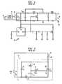
- FIG. 1is a circuit diagram of a prior art current regulator 50 connected to a dimmer switch 75 which provides phase modulation.
- FIG. 2is a circuit diagram of such a prior art dimmer switch 75 .
- the time constant of resistor 76 (R 1 ) and capacitor 77 (C 1 )control the firing angle “ ⁇ ” of the triac 80 (illustrated in FIG. 4 ).
- the diac 85is used to maximize symmetry between the firing angle for the positive and negative half cycles of the input AC line voltage ( 35 ).
- Capacitor 45 (C 2 ) and inductor 40 (L 1 )form a low pass filter to help reduce noise, generated by the dimmer switch 75 .
- a triac 80is a switching device effectively equivalent to reverse parallel Silicon Controlled Rectifiers (SCR), sharing a common gate.
- SCRSilicon Controlled Rectifiers
- the single SCRis a gate controlled semiconductor that behaves like a diode when turned on.
- the gate ( 70 ) signalis used to turn the device on and the load current is used to hold the device on. Thus, the gate signal cannot turn the SCR off and will remain on until the load current goes to zero.
- a triacbehaves like a SCR but conducts in both directions. Triacs are well known to have different turn on thresholds for positive and negative conduction. This difference is usually minimized by using a diac 85 coupled to the triac gate 70 to control the turn on voltage of the triac 80 .
- Triacs 80also have minimum latching and holding currents.
- the latching currentis the minimum current required to turn on the triac 80 when given a sufficient gate pulse.
- the holding currentis the minimum current required to hold the triac 80 in an on state once conducting. When the current drops below this holding current, the triac 80 will turn off.
- the latching currentis typically higher than the holding current.
- the holding and latching currentsare on the order of 10 mA to about 70 mA.
- the firing angle ( ⁇ ) of the triac 80controls the delay from the zero crossing of the AC line, and is limited between 0° and 180°, with 0° equating to full power and 180° to no power delivered to the load, with an exemplary phase-modulated output voltage illustrated in FIG. 4 .
- a typical dimmer switchmay have minimum and maximum ⁇ values of about 25° and 155° respectively, allowing about 98% to 2% of power to flow to the load compared to operation directly from the AC mains (AC line voltage ( 35 )).
- the firing angleis determined by the RC time constant of capacitor 77 (C 1 ), resistor 76 (R 1 ), and the impedance of the load, such as an incandescent bulb or an LED driver circuit (Z LOAD ).
- Z LOADwill be orders of magnitude lower than R 1 and resistive, thus will not affect the firing angle appreciably.
- the loadis comparable to R 1 or is not resistive, however, the firing angle and behavior of the dimmer switch can change dramatically.
- Typical prior art, off-line AC/DC converters that drive LEDs using phase modulation from a dimmer switchhave several problems associated with providing a quality drive to LEDs, such as: (1) such phase modulation from a dimmer switch can produce a low frequency (about 120 Hz) in the optical output, which can be detected by a human eye or otherwise create a reaction in people to the oscillating light; (2) filtering the input voltage may require quite a substantial value of the input capacitor, compromising both the size of the converter and its life; (3) when the triac 80 is turned on, a large inrush current may be created, due to a low impedance of the input filter, which may damage elements of both the dimmer switch 75 and any LED driver; and (4) power management controllers are typically not designed to operate in an environment having phase modulation of input voltage and could malfunction.
- a switching off-line LED driver 90typically includes a full wave rectifier 20 with a capacitive filter 15 , which allows current to flow to the filter capacitor (C FILT ) 15 , when the input voltage is greater than the voltage across the capacitor.
- the inrush current to the capacitoris limited by the resistance in series with the capacitor.
- NTCNegative Temperature Coefficient resistor
- This resistancewill be significantly reduced during operation, allowing for fast capacitor charging.
- This circuitwill continuously peak charge the capacitor to the peak voltage of the input waveform, 169 V DC for standard 120 V AC line voltage.
- the voltage across the filter capacitorcan be approximated to a DC voltage source due to the large difference between C 1 ( 77 ) and C FILT ( 15 ).
- the charging current of the filter capacitoris also the charging current for C 1 , which controls the firing angle of the dimmer.
- the charging current for C 1will be decreased from normal dimmer operation due to the large voltage drop across the filter capacitor 15 . For large values of V C1 , the current into C 1 will be small and thus slowly charge.
- the small charging currentmay not be enough to charge C 1 to the diac 85 breakover voltage during one half cycle. If the breakover voltage is not reached, the triac 80 will not turn on. This will continue through many cycles until the voltage on the filter capacitor is small enough to allow C 1 to charge to the breakover voltage. Once the breakover voltage has been reached, the triac 80 will turn on and the capacitor will charge to the peak value of the remaining half cycle input voltage.
- the triac 80When a dimmer switch is used with a load drawing or sinking a small amount of current, I LOAD ⁇ holding current for all values of the AC input, the triac 80 will provide inconsistent behavior unsuitable for applications with LED drivers.
- the nominal firing anglewill increase due to the increased resistance of Z LOAD 81 .
- the capacitor (C 1 ) voltageexceeds the diac breakover voltage, the diac 85 will discharge the capacitor into the gate of the triac 80 , momentarily turning the triac on. Because the load resistance is too high to allow the necessary holding current, however, the triac 80 will then turn off. When the triac turns off, the capacitor C 1 begins charging again through R 1 and Z LOAD ( 81 ).
- an LED driver circuitwhich can operate consistently with a typical or standard dimmer switch of the existing lighting infrastructure and avoid the problems discussed above, while providing the environmental and energy-saving benefits of LED lighting.
- Such an LED driver circuitshould be able to be controlled by standard switches of the existing lighting infrastructure to provide the same regulated brightness, such as for productivity, flexibility, aesthetics, ambience, and energy savings.
- Such an LED driver circuitshould be able to operate not only alone, but also in parallel with other types of lighting, such as incandescent lighting, and be controllable by the same switches, such as dimmer switches or other adaptive or programmable switches used with such incandescent lighting.
- Such an LED driver circuitshould also be operable within the existing lighting infrastructure, without the need for re-wiring or other retrofitting.
- the exemplary embodiments of the present inventionprovide numerous advantages.
- the exemplary embodimentsallow for solid state lighting, such as LEDs, to be utilized with the currently existing lighting infrastructure and to be controlled by any of a variety of switches, such as phase modulating dimmer switches, which would otherwise cause significant operation problems for conventional switching power supplies or current regulators.
- the exemplary embodimentsfurther allow for sophisticated control of the output brightness or intensity of such solid state lighting, and may be implemented using fewer and comparatively lower cost components.
- the exemplary embodimentsmay be utilized for stand-alone solid state lighting systems, or may be utilized in parallel with other types of existing lighting systems, such as incandescent lamps.
- Exemplary embodiments of the present inventiondisclose a current regulator (power converter) for providing variable power to solid state lighting, such as LEDs, in which the current regulator couplable through a phase-modulating switch to an AC line voltage.
- An exemplary current regulatorcomprises: a rectifier; a switching power supply providing a first current; and an impedance matching circuit coupled to the switching power supply and couplable to the phase-modulating switch or to the AC line voltage, the impedance matching circuit adapted to provide a second current through the phase-modulating switch when a magnitude of the first current is below a first predetermined threshold.
- the impedance matching circuitcomprises: a first resistor coupled to receive the first current from the switching power supply and provide a first voltage level; a second resistor; and a current switch coupled in series to the second resistor, the switch responsive to a control voltage to modulate the second current through the second resistor in response to the first voltage level.
- a controllermay be adapted to provide the control voltage.
- the phase-modulating switchhas a triac
- the first predetermined thresholdis at least a minimum holding current for the triac.
- a controlleris couplable to the phase-modulating switch, and the controller is adapted to determine a root-mean-square (RMS) voltage level provided by the phase-modulating switch from the AC line voltage, and to compare the RMS voltage level to a nominal voltage level.
- the controlleris further adapted to determine a duty cycle for pulse-width current modulation by the switching power supply in response to the comparison of the RMS voltage level to the nominal voltage level.
- RMSroot-mean-square
- the controllermay be further adapted to determine the duty cycle based on a ratio of about a power of 3.4 of the RMS voltage level (V RMS ) to about a power of 3.4 of the nominal voltage level (V N ) (V RMS 3.4 /V N 3.4 ), such as to determine the duty cycle “D” based on
- V RMSis the RMS value of the phase-modulated (or “chopped”) voltage and V N is the nominal voltage level (e.g., from the AC line voltage).
- the controlleris further adapted to determine the nominal voltage level provided by the phase-modulating switch from the AC line voltage when a phase angle of a phase-modulated voltage level is about zero, or to determine the nominal voltage level provided by the AC line voltage, or to determine the nominal voltage level as a predetermined parameter stored in a memory.
- the controllermay be further adapted to determine the RMS value of the phase-modulated (or chopped) voltage by determining an amplitude and a phase angle of a phase-modulated voltage level provided by the phase-modulating switch from the AC line voltage.
- a capacitor of the switching power supplyhas a capacitance sufficient to provide energy to the solid state lighting when the phase-modulating switch is not providing power from the AC line voltage.
- the switching power supplymay further comprises a first stage and a second stage, wherein the first stage is in an off-state when the phase-modulating switch is not providing power from the AC line voltage, and wherein the second stage is in an on-state when the phase-modulating switch is not providing power from the AC line voltage.
- the second stagemay be adapted to provide power to the solid state lighting when the phase-modulating switch is not providing power from the AC line voltage.
- the controllermay be adapted to control a charging of a capacitor in the switching power supply to a first predetermined level during a first time interval, such as when the phase-modulating switch is providing power from the AC line voltage.
- the controllermay be further adapted to determine the first predetermined level based upon a minimum voltage level of the solid state lighting and a voltage drop of the capacitor during a second time interval, such as when the phase-modulating switch is not providing power from the AC line voltage.
- the controlleralso may be further adapted to determine the first predetermined level voltage level as a function of the phase modulation performed by the phase-modulating switch, such as to determine the first predetermined level voltage level “V C ” as
- Another exemplary embodiment of the present inventionimplements a power converter for providing variable brightness levels for solid state lighting, with the power converter couplable to a phase-modulating switch which is couplable to an AC line voltage.
- the exemplary power convertercomprises: a switching power supply providing a first current; and an active impedance matching circuit coupled to the switching power supply, the active impedance matching circuit adapted to provide a variable, second current in response to a magnitude of the first current.
- the current regulatorcomprises: a rectifier; a switching power supply providing a first current; an impedance matching circuit coupled to the switching power supply and couplable to the phase-modulating switch or to the AC line voltage, the impedance matching circuit adapted to provide a second current through the phase-modulating switch when a magnitude of the first current is below a first predetermined threshold; and a controller coupled to the switching power supply and couplable to the phase-modulating switch, the controller adapted to determine a root-mean-square (RMS) voltage level provided by the phase-modulating switch from the AC line voltage and to determine a duty cycle for pulse-width current modulation by the switching power supply in response to the comparison of the RMS voltage level to a nominal voltage level.
- RMSroot-mean-square
- the current regulatorfor providing variable brightness levels for a plurality of light emitting diodes, with the current regulator couplable to a phase-modulating switch which is coupled to an AC line voltage.
- the current regulatorcomprises: a switching power supply providing a first current; and a controller coupled to the switching power supply and couplable to the phase-modulating switch, the controller adapted to provide power to the plurality of light emitting diodes when the phase-modulating switch is not providing power from the AC line voltage.
- FIG. 1is a circuit diagram of a prior art current regulator.
- FIG. 2is a circuit diagram of a prior art dimmer switch.
- FIG. 3is a graphical diagram illustrating premature startup in a prior art current regulator coupled to a dimmer switch which causes perceptible LED flicker.
- FIG. 4is a graphical diagram illustrating the phase modulated output voltage from a standard dimmer switch.
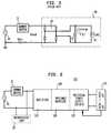
- FIG. 5is a high-level block and circuit diagram of a generalized prior art current regulator (or converter).
- FIG. 6is a block diagram of an exemplary first embodiment of a current regulator (or converter) in accordance with the teachings of the present invention.
- FIG. 7is a block diagram of an exemplary second embodiment of a current regulator (or converter) in accordance with the teachings of the present invention.
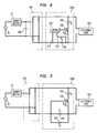
- FIG. 8is a circuit diagram of an exemplary first embodiment of an impedance matching circuit for a current regulator (or converter) in accordance with the teachings of the present invention.
- FIG. 9is a circuit diagram of an exemplary second embodiment of an impedance matching circuit for a current regulator (or converter) in accordance with the teachings of the present invention.
- FIG. 10is a circuit diagram of an exemplary embodiment of a switching power supply for a current regulator (or converter) in accordance with the teachings of the present invention.
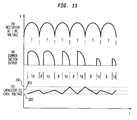
- FIG. 11is a graphical diagram selected voltages which may be found in exemplary embodiments of a current regulator (or converter) in accordance with the teachings of the present invention.
- an LED driver circuitis provided which is compatible for operation with the existing lighting infrastructure, such as dimmer switches, and may be coupled directly to and controlled by such dimmer switches.
- an LED driver circuitis provided which is couplable directly to an AC line voltage while nonetheless adapted to be controlled by a standard dimmer switch.
- LED driver circuits and LEDswill be wired within existing lighting infrastructure, such as replacing an incandescent bulb (placed within an Edison socket) or replacing an incandescent lamp, with wiring to existing switches, such as dimmer switches.
- existing switching connectionsmay be re-wired, allowing LED driver circuits to be co-located in the same junction or wall box as the switches, but wired directly to the AC line voltage, with existing switching (such as dimmers) generating only a control signal to regulate LED brightness.
- LED driver circuits with user interfacesmay completely replace the existing switching and lighting infrastructure, providing the most appropriate form of control for solid state lighting.
- such first phase technologyis based on an LED driver capable of working using the phase modulated (or chopped) AC signal from a standard dimmer switch 75 .
- this LED drivermay operate directly from the phase modulated AC signal under the control of the dimmer circuit, or may include an input circuit for emulating dimmer performance, similar to incandescent lamp requirements.
- very compact and highly efficient LED driversare provided, to meet anticipated size and thermal restrictions.
- Digital controllersmay also be utilized, as discussed below.
- dimmer switchesgenerally and initially will not be changed or rewired, so all of their existing performance characteristics will be maintained, such as power harmonics, inrush currents during initial powering on, electromagnetic interference, and audio harmonics (such as buzzing).
- power harmonicssuch as inrush currents during initial powering on, electromagnetic interference, and audio harmonics (such as buzzing).
- audio harmonicssuch as buzzing
- FIG. 6is a block diagram of an exemplary first embodiment of a current regulator (or converter) 100 in accordance with the teachings of the present invention.
- the current regulator 100provides power to one or more LEDs 140 , which may be an array or multiple arrays of LEDs 140 or any type or color, with the regulator 100 and LEDs 140 forming a system 105 .
- the current regulator 100is compatible with existing lighting infrastructure, and may be coupled directly to a dimmer switch 75 for receiving a phase-modulated AC voltage derived from the AC line voltage (AC Mains) ( 35 ).
- the current regulator 100may operate in parallel with an incandescent lamp 95 , under the common control of the dimmer switch 75 .
- the current regulator 100comprises a rectifier 10 , an impedance matching circuit 120 , and a switching power supply (or driver) 130 .
- the switching power supply 130in exemplary embodiments, may also be adapted to receive feedback from the LEDs 140 .
- FIG. 7is a block diagram of an exemplary second embodiment of a current regulator (or converter) 200 in accordance with the teachings of the present invention.
- the current regulator 200comprises a rectifier 110 , an impedance matching circuit 120 , a switching power supply (or driver) 150 , and further includes a controller 160 coupled to receive an output from the dimmer switch 75 .
- the current regulator 200also provides power to one or more LEDs 140 , which also may be an array or multiple arrays of LEDs 140 or any type or color, with the regulator 200 and LEDs 140 forming a system 180 .
- the current regulator 200may be coupled directly to a dimmer switch 75 (line 202 ) for receiving a phase-modulated AC voltage derived from the AC line voltage ( 35 ), and may operate in parallel with an incandescent lamp 95 , under the common control of the dimmer switch 75 .
- the current regulator 200may be coupled directly to the AC line voltage 35 (illustrated by dashed line 201 ), and also may operate in parallel with an incandescent lamp 95 .
- the controller 160(and 260 , FIG. 10 ) is programmed, adapted or configured to emulate the brightness or intensity control provided by the dimmer switch 75 , to control the switching power supply 150 and correspondingly modify the brightness (or intensity) provided by the LEDs 140 .
- the controller 160is adapted to determine the RMS (root-mean-square) voltage of the phase-modulated signal provided by the dimmer switch 75 (using V RMS sensor 165 ) (i.e., which may or may not be significantly phase-modulated at any given time), to determine the nominal voltage provided by the dimmer switch 75 without dimming (when ⁇ 0) or by the AC line voltage 35 (using V NOMINAL sensor 170 or a V NOMINAL parameter stored memory 155 ) (i.e., the RMS value of the full or non-phase-modulated voltage provided by the AC line voltage 35 or provided by the dimmer switch 75 when ⁇ is zero or close to or about zero ( ⁇ 0)), and to provide a control signal to the switching power supply 150 , using control logic block 175 .
- V RMS sensor 165i.e., which may or may not be significantly phase-modulated at any given time
- the RMS and nominal voltage sensors 165 , 170are utilized to provide emulation of the optical performance of an incandescent lamp 95 .
- the RMS voltage V RMSwill refer to the RMS value of the “chopped” voltage of the phase-modulated signal (e.g., provided by the dimmer switch 75 )
- the nominal voltage V NOMINALor V N
- V Nwill refer the RMS value of the voltage of the full or non-phase-modulated signal provided by the AC line voltage 35 or provided by the dimmer switch 75 when ⁇ is zero or close to or about zero.
- V RMSUnder conditions of dimming (when ⁇ >0), V RMS will be less than V NOMINAL .
- the exemplary embodimentsadvantageously utilize a ratio of V RMS to V NOMINAL to control and provide variable brightness or intensity levels of the optical output of the LEDs 140 . More specifically, the exemplary embodiments provide for emulating the optical output of incandescent lamps utilizing such a ratio of V RMS and V NOMINAL , each raised to a selected power which, in exemplary embodiments, is about 3.4, as discussed below.
- the impedance matching circuit 120provides an appropriate output impedance for a dimmer switch 75 to maintain its minimum holding current, creates a series impedance with the RC network ( 76 , 77 ) of the dimmer switch 75 to ensure a correct firing angle when it is interconnected with a switching LED driver, and provides an appropriate input impedance for a stable operation of the switching LED driver 100 , 200 and systems 105 , 180 .
- the impedance matching circuit 120is a combination of active and passive components adapted to meet the requirements of both the dimmer switch 75 and the regulators (converters or drivers) 100 , 200 .
- the exemplary embodiments of the impedance matching circuit 120(1) provide sufficient holding current for the dimmer switch 75 to remain in an on-state, independently of the load current; (2) provide a path for the gating circuit (capacitor 77 , resistor 76 and diac 85 ) of the dimmer switch 75 to fire correctly (and avoid the premature start up and improper firing illustrated in FIG. 3 ); and (3) reduce the amount of current through the impedance matching circuit 120 when sufficient current is provided by a corresponding load.
- One comparatively inefficient, prior art method to create impedance matchingwould be to simply use a load resistor, R L , across the dimmer switch 75 , thereby providing a load current of at least V TRIAC /R L when the triac 80 is firing.
- R Lload resistor
- the currentcan be made sufficiently high to ensure that it is always above the threshold current (typically in the vicinity of 50 mA ⁇ 100 mA) needed to keep the triac 80 in an on state.
- the power dissipation across the resistor R Lwould be extremely high, i.e., 120 2 /R L when the phase angle (firing angle ⁇ ) is small, further resulting in creation of significant heat.
- Such a load resistanceit typically provided by an incandescent lamp, but is not automatically provided by an electronic or switchable load, such as a switching LED driver system.
- an active circuitis used which is capable of adjusting its impedance according to the needs of the dimmer switch 75 .
- the active loadwould only supplement the current necessary to allow the triac 80 to switch on (fire) and to hold it in an on-state as desired.
- the exemplary embodimentsare also more power efficient, reducing the supplemented current (and therefore I 2 R power loss) when there are other loads providing or sinking currents or when the phase angle ⁇ is small.
- FIG. 8is a circuit diagram of an exemplary first embodiment of an impedance matching circuit 120 A for a current regulator (or converter) 100 , 200 in accordance with the teachings of the present invention.
- the “electronic” load 250for example, is a system 105 , 180 , such as a current regulator (or converter) 100 , 200 coupled to LEDs 140 .
- the impedance matching circuit 120 Ahas small power loss. Using a control signal such as a control voltage from control block 215 , impedance matching circuit 120 A can insert extra or additional current for the dimmer switch 75 to turn on the triac 80 and sustain an on-state when the load current is insufficient.
- the control signalmay be provided from a variety of sources, such as from a controller 160 , 260 (not separately illustrated). Such a control signal, for example, may be derived from a detected voltage across current sense resistor 220 , as an indicator of the load current.
- the control block 215e.g., controller 160 , 260
- the control block 215may be coupled (lines 211 , 212 ) to detect or otherwise receive feedback of the voltage across current sense resistor 220 .
- the impedance matching circuit 120 AWhen the load current, which goes through sensing resistor 220 (R C ), is too small and unable to fire the triac 80 in the dimmer switch 75 , the impedance matching circuit 120 A operates as a linear regulator to insert needed extra current, turning on switch 230 and providing for increased current through resistor 210 .
- the impedance matching circuit 120 Aprovides a regulated impedance based on the condition of the electronic load 250 , and extra power loss is reduced.
- a typical electronic loadfor example and without limitation, would be a current regulator 100 , 200 coupled to LEDs 140 .
- the resistance of resistor 210 (R B )limits the maximum current that can be provided through the switch 230 .
- the switch 230is turned off when load current can create sufficient voltage on resistor 220 (R C ).
- An optional capacitor 260(providing an EMI filter) (e.g., typically 0.47 uF (impedance 5-6 k Ohms)) can be used to provide an extra current (e.g., 20 mA) and further reduce losses. While illustrated as an n-channel enhancement MOSFET, any type of switch 230 may be utilized, including a depletion-mode FET ( 235 ) illustrated in FIG. 9 or any other type of FET, JFET, BJT, hybrid IGBT, etc.
- the impedance matching circuit 120 Acan operate both in a linear mode and a switched mode.
- the gate-to-source voltage of the switchmay be varied throughout the linear operational region, from below the threshold voltage, to the threshold voltage and up to the saturation voltage, to modulate the amount of current through resistor 210 .
- the gate-to-source voltage of the switchmay be either below the threshold voltage or at or above the saturation voltage, to correspondingly provide either no current or a full (saturation) level of current, respectively, such that the amount of supplemented current is limited by the value of the resistance of resistor 210 in the latter case.
- FIG. 9is a circuit diagram of an exemplary second embodiment of an impedance matching circuit 120 B for a current regulator (or converter) 100 , 200 in accordance with the teachings of the present invention.
- the impedance matching circuit 120 Butilizes a MOSFET switch 235 , implemented as a depletion MOSFET (illustrated as n-channel MOSFET), having an on-state (and fully conducting) as a default mode when its gate-to-source voltage is above a threshold voltage (which may be zero volts, for example), and becomes less conducting an ultimately enters an off-state (non-conducting) when its gate-to-source voltage is below the threshold voltage (i.e., more negative than the threshold voltage).
- a threshold voltagewhich may be zero volts, for example
- the switch 235When utilized with a control circuit (e.g., 215 or a controller 160 , 260 , not separately illustrated), rather than the gate connection to the sense resistor 220 , the switch 235 may also be operated in either switched or linear modes as discussed above. As illustrated in FIG. 9 , the switch 235 will operate in a linear mode, with its gate-to-source voltage varying in response to the voltage generated across the current sense resistor 220 .
- resistor 210When conducting, current can be provided through resistor 210 , enabling sufficient current to maintain a holding current for the dimmer switch 75 .
- the voltage generated across the resistor 220is utilized to gate (or modulate) and turn off the switch 235 , as those (negative) voltages approach or become more negative than the threshold voltage of the switch 235 , and thereby reduce the current through resistor 210 .
- Voltage limitation of the gate-to-source voltageis provided by a zener diode 225 , although other types of voltage limiters may be utilized equivalently.
- Resistors 210 and 220are sized appropriately to generate the desired voltages and corresponding levels of current, to provide the corresponding voltages for the selected switching or gating of the MOSFET switch 235 as additional current may or may not be needed.
- the control voltageis the gate-to-source voltage, and is automatically generated by a current through the current sense resistor 220 , with the total voltage being limited by a voltage limiter such as the zener diode 225 .
- a control circuit 215(or controller 160 , 260 ) may be utilized instead, as illustrated in FIG. 8 , and may provide either or both linear and switched modes.
- the impedance matching circuit 120may be located in a wide variety of places in the various systems 105 , 180 .
- the impedance matching circuit 120may be positioned between the rectifier 110 and any applicable load 250 , as illustrated in FIGS. 8 and 9 .
- the impedance matching circuit 120may be placed before or in advance of the rectifier 110 (i.e., across the dimmer switch 75 and the AC line voltage 35 ), as illustrated in FIG. 10 .
- the impedance matching circuit 120may be placed in any circuit position in parallel with the load 250 to provide the novel current sinking of the present invention.
- the operation of the controller 160may be described in greater detail, for controlling the brightness or intensity of the optical output of LEDs 140 , independently or in parallel with an incandescent lamp 95 .
- Optical output of an incandescent lamp or bulbis proportional to the RMS voltage across its filament in about a power of 3.4, namely, F ⁇ V 3.4 , where F is the Flux in Lm, and V is the RMS voltage.
- the dimming of the LEDs 140is controlled through corresponding changes in the duty cycle of a pulse-width modulated (“PWM”) driver, such as the drivers within a switching power supply 150 (or the drivers of FIG.
- PWMpulse-width modulated
- This duty cycleis calculated based on the ratio of the sensed RMS phase modulated voltage signal (V RMS ) to a nominal RMS AC line voltage V NOMINAL (from AC line voltage 35 , from a dimmer switch 75 when ⁇ 0, or from a V NOMINAL parameter stored in memory 155 ). Accordingly, assuming an approximately linear dependence of optical output from LEDs 140 with the duty cycle of providing energy to the LEDs 140 , the novel and inventive approach to duty cycle adjustment for PWM may be expressed as (Equation 1):
- Dis the operational duty cycle for PWM dimming of LEDs 140 ;
- V RMSis the operational RMS voltage during phase-modulation;
- the brightness controlconsists of the following steps: (1) regulating brightness by phase modulation of the input AC voltage, such as through a dimmer switch 75 ; (2) applying the phase modulated voltage to the incandescent lamp 95 ; (3) measuring the RMS value of phase modulated voltage V RMS , such as using V RMS sensor 165 in controller 160 , 260 ; (4) calculating the duty ratio (duty cycle) D for LED 140 dimming as proportional to corresponding changes of RMS voltage (i.e., the change in V RMS compared to V NOMINAL ), thereby emulating the optical output of the incandescent lamps 95 ; and (5) dimming LEDs 140 through pulse width modulation of their current, keeping the amplitude of the current constant and the duty ratio variable to emulate the perceived output of an incandescent lamp.
- this methodologymay be implemented in a controller 160 (or 260 ).
- the dimming of LEDs 140is effectively identical or similar in brightness to the dimming of incandescent lamps or bulbs on the same switch.
- this methodologymay be implemented without supplying the phase-modulated AC voltage from the dimmer switch 75 to the current regulator (or converter) 200 (on line 202 ).
- the current regulator (or converter) 200may be coupled directly to the AC line voltage (line 201 ), with corresponding dimming provided through the operation of the controller 160 by emulation of incandescent dimming.
- the RMS voltage V RMSmay be sensed using a wide variety of methods.
- a first proposed methodutilizes an RMS converter of the phased-modulated signal provided by the dimmer switch 75 .
- a second proposed method of sensing the RMS voltageis based on measurements of the duty ratio of the firing angle ⁇ of the dimmer switch 75 to the half cycle angle ( ⁇ ) and the amplitude of the operational AC voltage, and then calculating the RMS value of the phase modulated signal.
- the nominal RMS voltage V NOMINALmay also be measured or calculated as described above, such as using a voltage measurement directly from the AC line voltage 35 , or measured (sensed) from the phase-modulating dimmer switch 75 when ⁇ 0.
- the nominal RMS voltage V NOMINALmay also be calculated or predetermined, such as using a calculated value assuming typical or standard voltage and frequency levels provided by the AC line voltage 35 , e.g., 115 V, with a V NOMINAL parameter value for the nominal RMS voltage stored in memory 155 .
- V NOMINAL(or, equivalently, V N ) may be calculated and stored as a parameter in a memory circuit 155 , such as a FLASH or other programmable memory, as an expected or anticipated value of the nominal AC voltage.
- the V NOMINAL sensor 170may be implemented similarly to the V RMS sensor 165 , to measure a voltage level under full brightness conditions (no dimming, when a is zero) or measured directly from the AC line voltage 35 .
- FIG. 10is a circuit diagram of an exemplary embodiment of a switching power supply 150 A for a current regulator (or converter) 100 , 200 in accordance with the teachings of the present invention.
- FIG. 11is a graphical diagram selected voltages which may be found in exemplary embodiments of a current regulator (or converter) 100 , 200 or system 105 , 180 in accordance with the teachings of the present invention.
- two modes of operation of the current regulator (or converter) 100 , 200are provided.
- a first modewhen the dimmer switch 75 is not providing any power (is non-conducting), such as in the “ ⁇ ” time intervals illustrated in FIG. 11 , the current regulator (or converter) 100 , 200 is in an off-state and no power is provided to the LEDs 140 .
- Operation in this first modemay be provided through the selection of capacitors having comparatively smaller capacitance values, as discussed below, using virtually any type of switching power supply.
- a second modesuch as for the switching power supply 150 A illustrated in FIG.
- the current regulator (or converter) 100 , 200is still in an on-state and power continues to be provided to the LEDs 140 .
- Operation in this second modemay be provided through the selection of capacitors having comparatively larger capacitance values, as discussed below, using a somewhat more sophisticated switching power supply, such as the two-stage switching power supply 150 A.
- the switching power supply 150 Ais coupled via impedance matching circuit 120 to a phase modulation module/dimmer, such as a dimmer switch 75 , and is intended to operate in the second mode of operation mentioned above.
- the switching power supply 150 Ais implemented in two stages, an AC/DC converter 265 and a buck converter 270 .
- the AC/DC converter 265is utilized to provide a high input impedance, thereby eliminating the high input capacitance that the single stage approaches have (and which can cause triacs of dimmers to misfire, as previously mentioned).
- This first stagewill convert a relatively poor, phased modulated AC voltage into a manageable DC voltage, while the second stage (buck converter 270 ) will perform LED driving using current PWM, through switching transistor 355 (Q 2 ).
- the quadratic AC/DC converter 265 portion of switching power supply 150 Ais connected to the dimmer switch 75 via an impedance matching circuit 120 .
- the AC/DC converter 265comprises major elements such as switch Q 1 ( 300 ), inductors L 2 ( 305 ) and L 3 ( 310 ), capacitors C 4 ( 330 ) and C 5 ( 345 ), diodes D 1 ( 315 ) and D 2 ( 320 ), and current sense resistor R 2 ( 340 ).
- Buck converter 270 portion of switching power supply 150 Agenerally comprises a switching transistor Q 2 ( 355 ) (for dimming), inductor L 4 ( 375 ), capacitor C 3 ( 370 ), and current sense resistor R 4 ( 360 ).
- the switching power supply 150 Aalso comprises controller 260 , which provides the functionality of the controller 160 previously discussed, and the additional functionality discussed below.
- the controller 260may determine V RMS using measurements from connections to the output of dimmer switch 75 on lines 381 and 382 ; may determine V NOMINAL using measurements from connections to the output of dimmer switch 75 on lines 381 and 382 , using measurements from connections to the AC line voltage 35 on lines 382 and 383 (dashed line), or using stored parameter values.
- the controller 260correspondingly adjusts the duty cycle of the pulse-width modulation of current provided to the LEDs 140 through switching transistor 355 (Q 2 ).
- the current regulator (or converter) 100 , 200is in an off-state and no power is provided to the LEDs 140 .
- phase-modulated currentis provided to the impedance matching circuit 120 and the bridge rectifier 110 .
- Switch Q 1 ( 300 )is typically switched on and off at a comparatively high frequency.
- energyis stored in inductor L 2 ( 305 ) and inductor L 3 ( 310 .
- Q 1 ( 300 )is off, the energy stored in inductor L 2 is transferred to capacitor C 4 ( 330 ), and the energy stored in inductor L 3 is transferred to capacitor C 5 ( 345 ).
- energy stored in capacitor C 5 ( 345 )is provided as current to LEDs 140 , using PWM controlled by controller 260 through switch Q 2 ( 355 ), with the duty cycle of PWM determined as discussed above.
- the quadratic AC/DC converter 265When the dimmer switch 75 is not providing any power (is non-conducting) (in the “ ⁇ ” time intervals) the quadratic AC/DC converter 265 is effectively turned off, with the controller 260 turning off switch Q 1 ( 300 ).
- the second stage of the switching power supply 150 , converter 270continues to operate and provide LEDs 140 with a regulated current (i.e., operates continuously, during both Td and ⁇ time intervals).
- capacitor C 5 ( 345 )has a sufficient capacitance value, it has sufficient stored energy to continue to provide PWM current to LEDs 140 , with the PWM also controlled by controller 260 through switch Q 2 ( 355 ), and with the duty cycle of PWM determined as discussed above.
- capacitor C 4 ( 330 )may also be provided with a comparatively large capacitance value.
- the voltage level of capacitor C 5 ( 345 ) “V C ”is always maintained at or above the voltage level required by the LEDs 140 (“V LED ”), illustrated by line 390 in FIG. 11 , part C.
- V LEDthe voltage level required by the LEDs 140
- the capacitor C 5 ( 345 )is charged to a sufficiently high voltage such that, when it is discharged during the “ ⁇ ” time intervals when the dimmer switch 75 is not providing any power, its voltage level V C does not drop below the minimum voltage required to energize the LEDs 140 to provide optical output.
- these intervals Td and “ ⁇ ”may (and typically will) be variable, as illustrated in FIG. 11 .
- these intervals Td and “ ⁇ ”may (and typically will) be variable, as illustrated in FIG. 11 .
- capacitor C 5 ( 345 )is charged to a higher voltage level, illustrated as line 392 in FIG. 11
- capacitor C 5 ( 345 )is charged to a comparatively lower voltage level, illustrated as line 391 in FIG. 11 .
- Control of the charging to these voltage levelsis provided by controller 260 , using the methodology described below.
- ⁇ ⁇ ⁇ V c +I D ⁇ T d C , where I D is the average charging current, and Td is the time period during which the phase-modulated, rectified AC voltage is greater than zero, i.e., 0 ⁇ Td ⁇ T, as illustrated in FIG. 11B and discussed above.
- V cV LED + I m ⁇ ⁇ l ⁇ D ⁇ T C . It should be noted that strict equality of these various relations is not required, and some variation is allowable and expected.
- Equation 5the voltage level V C to which capacitor C 5 ( 345 ) should be allowed to charge during the Td time intervals, under the control of the controller 260 , may be expressed equivalently as (Equation 5):
- the voltage level V Cmay be sensed or measured, such as via the illustrated connection from the capacitor C 5 ( 345 ) to the controller 260 . Accordingly, the controller 260 provides various control signals to the switch 300 , during the Td intervals, to control the charging of capacitor C 5 ( 345 ).
- the voltage across capacitor C 5 ( 345 )should be charged according to Equations 4 and/or 5 to the value V C (illustrated in FIG. 11 , part C, which illustrates two different voltage levels for V C , on lines 391 and 392 , and the minimum voltage level for V C , namely V LED , on line 390 ). Accordingly, the voltage regulator of the phase modulated AC/DC converter will have a variable set value for the capacitor C 5 ( 345 ) voltage, based on Equations 4 and/or 5, given the degree of phase modulation.
- the proposed power stage 265 of the converter 100 , 200has the following features making it compatible with the phase modulated input voltage: (1) a relatively high input impedance (no input filter capacitor) in order to facilitate the design of the impedance matching circuit 120 ; (2) it allows very wide conversion ratios from input to output DC Voltages, avoiding overly-small duty cycles; (3) it uses a relatively small, low filtering capacitor for low frequency ripple, or can allow this ripple to be comparatively high (with filtering in the second stage 270 ), so smaller and/or a non-electrolytic capacitor may be used (such as a film or ceramic capacitor), decreasing costs and extending the life of the driver; (4) it has built-in capability to deliver power factor correction without additional power components; and (5) it has a small size, fewer components, comparatively lower cost, and high efficiency.
- the exemplary embodimentsallow for solid state lighting, such as LEDs, to be utilized with the currently existing lighting infrastructure and to be controlled by any of a variety of switches, such as phase modulating dimmer switches, which would otherwise cause significant operation problems.
- the exemplary embodimentsfurther allow for sophisticated control of the output brightness or intensity of such solid state lighting, and may be implemented using fewer and comparatively lower cost components.
- the exemplary embodimentsmay be utilized for stand-alone solid state lighting systems, or may be utilized in parallel with other types of existing lighting systems, such as incandescent lamps.
- Coupledmeans and includes any direct or indirect electrical, structural or magnetic coupling, connection or attachment, or adaptation or capability for such a direct or indirect electrical, structural or magnetic coupling, connection or attachment, including integrally formed components and components which are coupled via or through another component.
- LEDand its plural form “LEDs” should be understood to include any electroluminescent diode or other type of carrier injection- or junction-based system which is capable of generating radiation in response to an electrical signal, including without limitation, various semiconductor- or carbon-based structures which emit light in response to a current or voltage, light emitting polymers, organic LEDs, and so on, including within the visible spectrum, or other spectra such as ultraviolet or infrared, of any bandwidth, or of any color or color temperature.
- a “controller” or “processor” 160 , 260may be any type of controller or processor, and may be embodied as one or more controllers 160 , 260 , adapted to perform the functionality discussed herein.
- a controller 160 , 260may include use of a single integrated circuit (“IC”), or may include use of a plurality of integrated circuits or other components connected, arranged or grouped together, such as controllers, microprocessors, digital signal processors (“DSPs”), parallel processors, multiple core processors, custom ICs, application specific integrated circuits (“ASICs”), field programmable gate arrays (“FPGAs”), adaptive computing ICs, associated memory (such as RAM, DRAM and ROM), and other ICs and components.
- DSPsdigital signal processors
- ASICsapplication specific integrated circuits
- FPGAsfield programmable gate arrays
- adaptive computing ICsassociated memory (such as RAM, DRAM and ROM), and other ICs and components.
- controllershould be understood to equivalently mean and include a single IC, or arrangement of custom ICs, ASICs, processors, microprocessors, controllers, FPGAs, adaptive computing ICs, or some other grouping of integrated circuits which perform the functions discussed below, with associated memory, such as microprocessor memory or additional RAM, DRAM, SDRAM, SRAM, MRAM, ROM, FLASH, EPROM or E 2 PROM.
- a controller (or processor)(such as controller 160 , 260 ), with its associated memory, may be adapted or configured (via programming, FPGA interconnection, or hard-wiring) to perform the methodology of the invention, as discussed below.
- the methodologymay be programmed and stored, in a controller 160 , 260 with its associated memory (and/or memory 155 ) and other equivalent components, as a set of program instructions or other code (or equivalent configuration or other program) for subsequent execution when the processor is operative (i.e., powered on and functioning).
- the controller 160 , 260may implemented in whole or part as FPGAs, custom ICs and/or ASICs, the FPGAs, custom ICs or ASICs also may be designed, configured and/or hard-wired to implement the methodology of the invention.
- controller 160 , 260may be implemented as an arrangement of controllers, microprocessors, DSPs and/or ASICs, collectively referred to as a “controller”, which are respectively programmed, designed, adapted or configured to implement the methodology of the invention, in conjunction with a memory 155 .
- the memory 155which may include a data repository (or database), may be embodied in any number of forms, including within any computer or other machine-readable data storage medium, memory device or other storage or communication device for storage or communication of information, currently known or which becomes available in the future, including, but not limited to, a memory integrated circuit (“IC”), or memory portion of an integrated circuit (such as the resident memory within a controller 160 , 260 or processor IC), whether volatile or non-volatile, whether removable or non-removable, including without limitation RAM, FLASH, DRAM, SDRAM, SRAM, MRAM, FeRAM, ROM, EPROM or E 2 PROM, or any other form of memory device, such as a magnetic hard drive, an optical drive, a magnetic disk or tape drive, a hard disk drive, other machine-readable storage or memory media such as a floppy disk, a CDROM, a CD-RW, digital versatile disk (DVD) or other optical memory, or any other type of memory, storage medium, or data storage apparatus or circuit, which is
- Such computer readable mediaincludes any form of communication media which embodies computer readable instructions, data structures, program modules or other data in a data signal or modulated signal, such as an electromagnetic or optical carrier wave or other transport mechanism, including any information delivery media, which may encode data or other information in a signal, wired or wirelessly, including electromagnetic, optical, acoustic, RF or infrared signals, and so on.
- the memory 155may be adapted to store various look up tables, parameters, coefficients, other information and data, programs or instructions (of the software of the present invention), and other types of tables such as database tables.
- the controller 160 , 260is programmed, using software and data structures of the invention, for example, to perform the methodology of the present invention.
- the system and method of the present inventionmay be embodied as software which provides such programming or other instructions, such as a set of instructions and/or metadata embodied within a computer readable medium, discussed above.
- metadatamay also be utilized to define the various data structures of a look up table or a database.
- Such softwaremay be in the form of source or object code, by way of example and without limitation. Source code further may be compiled into some form of instructions or object code (including assembly language instructions or configuration information).
- the software, source code or metadata of the present inventionmay be embodied as any type of code, such as C, C++, SystemC, LISA, XML, Java, Brew, SQL and its variations (e.g., SQL 99 or proprietary versions of SQL), DB2, Oracle, or any other type of programming language which performs the functionality discussed herein, including various hardware definition or hardware modeling languages (e.g., Verilog, VHDL, RTL) and resulting database files (e.g., GDSII).
- codesuch as C, C++, SystemC, LISA, XML, Java, Brew, SQL and its variations (e.g., SQL 99 or proprietary versions of SQL), DB2, Oracle, or any other type of programming language which performs the functionality discussed herein, including various hardware definition or hardware modeling languages (e.g., Verilog, VHDL, RTL) and resulting database files (e.g., GDSII).
- a “construct”, “program construct”, “software construct” or “software”, as used equivalently herein,means and refers to any programming language, of any kind, with any syntax or signatures, which provides or can be interpreted to provide the associated functionality or methodology specified (when instantiated or loaded into a processor or computer and executed, including the controller 160 , 260 , for example).
- the software, metadata, or other source code of the present invention and any resulting bit filemay be embodied within any tangible storage medium, such as any of the computer or other machine-readable data storage media, as computer-readable instructions, data structures, program modules or other data, such as discussed above with respect to the memory 155 , e.g., a floppy disk, a CDROM, a CD-RW, a DVD, a magnetic hard drive, an optical drive, or any other type of data storage apparatus or medium, as mentioned above.
- any signal arrows in the drawings/ Figuresshould be considered only exemplary, and not limiting, unless otherwise specifically noted. Combinations of components of steps will also be considered within the scope of the present invention, particularly where the ability to separate or combine is unclear or foreseeable.
- the disjunctive term “or”, as used herein and throughout the claims that follow,is generally intended to mean “and/or”, having both conjunctive and disjunctive meanings (and is not confined to an “exclusive or” meaning), unless otherwise indicated.
- “a”, “an”, and “the”include plural references unless the context clearly dictates otherwise.
- the meaning of “in”includes “in” and “on” unless the context clearly dictates otherwise.
Landscapes
- Circuit Arrangement For Electric Light Sources In General (AREA)
Abstract
Description
in which VRMSis the RMS value of the phase-modulated (or “chopped”) voltage and VNis the nominal voltage level (e.g., from the AC line voltage).
where Imlis an amplitude of current through the solid state lighting, T is a half-cycle time of the AC line voltage, and C is the capacitance of the capacitor, VRMSis an RMS voltage level provided by the phase-modulating switch, and VNis a nominal voltage level of the AC line voltage.
where D is the operational duty cycle for PWM dimming of
where Imlis the amplitude of the LED current, D is the Dimming Duty Cycle, T is the half-cycle time of the input AC Voltage (illustrated in
where IDis the average charging current, and Td is the time period during which the phase-modulated, rectified AC voltage is greater than zero, i.e., 0<Td<T, as illustrated in
It should be noted that strict equality of these various relations is not required, and some variation is allowable and expected.
also illustrating a non-strict equality for the control of the voltage level VC.
Claims (79)
Priority Applications (1)
| Application Number | Priority Date | Filing Date | Title |
|---|---|---|---|
| US11/655,308US7902769B2 (en) | 2006-01-20 | 2007-01-19 | Current regulator for modulating brightness levels of solid state lighting |
Applications Claiming Priority (2)
| Application Number | Priority Date | Filing Date | Title |
|---|---|---|---|
| US76015706P | 2006-01-20 | 2006-01-20 | |
| US11/655,308US7902769B2 (en) | 2006-01-20 | 2007-01-19 | Current regulator for modulating brightness levels of solid state lighting |
Publications (2)
| Publication Number | Publication Date |
|---|---|
| US20070182338A1 US20070182338A1 (en) | 2007-08-09 |
| US7902769B2true US7902769B2 (en) | 2011-03-08 |
Family
ID=38333366
Family Applications (1)
| Application Number | Title | Priority Date | Filing Date |
|---|---|---|---|
| US11/655,308Active2029-10-07US7902769B2 (en) | 2006-01-20 | 2007-01-19 | Current regulator for modulating brightness levels of solid state lighting |
Country Status (1)
| Country | Link |
|---|---|
| US (1) | US7902769B2 (en) |
Cited By (68)
| Publication number | Priority date | Publication date | Assignee | Title |
|---|---|---|---|---|
| US20090160358A1 (en)* | 2007-12-24 | 2009-06-25 | Lightech Electronic Industries Ltd. | Controller and method for controlling an intensity of a light emitting diode (led) using a conventional ac dimmer |
| US20090167207A1 (en)* | 2006-06-22 | 2009-07-02 | Tridonicatco Gmbh Co. Kg | Dimmable Operating Device having Internal Dimming Characteristic |
| US20090179592A1 (en)* | 2008-01-14 | 2009-07-16 | Tai-Her Yang | Uni-directional light emitting diode drive circuit in pulsed power non-resonance |
| US20090179585A1 (en)* | 2008-01-14 | 2009-07-16 | Tai-Her Yang | Uni-directional light emitting diode drvie circuit in bi-directional divided power impedance |
| US20090195168A1 (en)* | 2008-02-05 | 2009-08-06 | Intersil Americas Inc. | Method and system for dimming ac-powered light emitting diode (led) lighting systems using conventional incandescent dimmers |
| US20090200951A1 (en)* | 2008-02-08 | 2009-08-13 | Purespectrum, Inc. | Methods and Apparatus for Dimming Light Sources |
| US20090251068A1 (en)* | 2008-04-07 | 2009-10-08 | Metrospec Technology, Llc | Solid State Lighting Circuit and Controls |
| US20090284182A1 (en)* | 2008-05-15 | 2009-11-19 | Marko Cencur | Method For Dimming Non-Linear Loads Using An AC Phase Control Scheme And A Universal Dimmer Using The Method |
| US20100213870A1 (en)* | 2007-10-22 | 2010-08-26 | Nxp B.V. | Dimmer jitter correction |
| US20100277067A1 (en)* | 2009-04-30 | 2010-11-04 | Lighting Science Group Corporation | Dimmable led luminaire |
| US20110012530A1 (en)* | 2009-07-14 | 2011-01-20 | Iwatt Inc. | Adaptive dimmer detection and control for led lamp |
| US20110109244A1 (en)* | 2009-10-28 | 2011-05-12 | Once Innovations, Inc. | Architecture for high power factor and low harmonic distortion led lighting |
| US20110175543A1 (en)* | 2008-09-25 | 2011-07-21 | Koninklijke Philips Electronics N.V. | Driver for providing variable power to a led array |
| US20110181197A1 (en)* | 2007-08-07 | 2011-07-28 | Rohm Co., Ltd. | Light source turn-on/off controller |
| US20110249069A1 (en)* | 2010-04-12 | 2011-10-13 | Oyama Tadaaki | Light source driving device, and image processing device, image reading device and image forming apparatus using the light source driving device |
| US20110316446A1 (en)* | 2010-06-25 | 2011-12-29 | Power Integrations, Inc. | Power converter with compensation circuit for adjusting output current provided to a constant load |
| US20120146525A1 (en)* | 2009-04-24 | 2012-06-14 | City University Of Hong Kong | Apparatus and methods of operation of passive and active led lighting equipment |
| US20120194091A1 (en)* | 2011-01-31 | 2012-08-02 | Microsemi Corp. - Analog Mixed Signal Group Ltd. | User control of an led luminaire for a phase cut dimmer |
| US20120242238A1 (en)* | 2011-03-22 | 2012-09-27 | Richtek Technology Corporation | Light Emitting Device Power Supply Circuit, and Light Emitting Device Driver Circuit and Control Method Thereof |
| US8283875B2 (en) | 2009-10-26 | 2012-10-09 | Light-Based Technologies Incorporated | Holding current circuits for phase-cut power control |
| US20120319587A1 (en)* | 2011-06-17 | 2012-12-20 | Stevan Pokrajac | Light emitting diode driver circuit |
| US20130015813A1 (en)* | 2011-07-14 | 2013-01-17 | Samsung Electronics Co., Ltd. | Wireless power receiver |
| US8500456B1 (en) | 2008-03-18 | 2013-08-06 | Metrospec Technology, L.L.C. | Interconnectable circuit boards |
| US8508330B1 (en)* | 2009-05-25 | 2013-08-13 | Cypress Semiconductor Corporation | Adaptive filter for lighting assembly control signals |
| US8525193B2 (en) | 2008-03-06 | 2013-09-03 | Metrospec Technology Llc | Layered structure for use with high power light emitting diode systems |
| US20130342122A1 (en)* | 2011-03-07 | 2013-12-26 | Rohm Co., Ltd. | Switching current control circuit, led dimmer system, and led illumination device |
| US8686668B2 (en) | 2009-10-26 | 2014-04-01 | Koninklijke Philips N.V. | Current offset circuits for phase-cut power control |
| US20140117866A1 (en)* | 2012-10-26 | 2014-05-01 | Liteideas, Llc | Apparatus and method of operation of a low-current LED lighting circuit |
| US20140125240A1 (en)* | 2011-05-06 | 2014-05-08 | Luca Bordin | Dimmable LED Driver And Method For Controlling The Same |
| US20140125239A1 (en)* | 2012-11-02 | 2014-05-08 | Texas Instruments Incorporated | Circuits and methods for reducing flicker in an led light source |
| US8851356B1 (en) | 2008-02-14 | 2014-10-07 | Metrospec Technology, L.L.C. | Flexible circuit board interconnection and methods |
| US8860326B2 (en) | 2012-03-21 | 2014-10-14 | Electronic Theatre Controls, Inc. | Dimmable light emitting diode lighting system |
| US20150015153A1 (en)* | 2010-09-02 | 2015-01-15 | Bcd Semiconductor Manufacturing Limited | Circuit and method for driving led lamp with a dimmer |
| US20150098708A1 (en)* | 2013-10-07 | 2015-04-09 | Panasonic Corporation | Visible light communication apparatus |
| US9006987B2 (en) | 2012-05-07 | 2015-04-14 | Lighting Science Group, Inc. | Wall-mountable luminaire and associated systems and methods |
| US20150116026A1 (en)* | 2013-10-31 | 2015-04-30 | General Electric Company | Voltage adapter systems for use in an appliance |
| US20150303694A1 (en)* | 2013-01-30 | 2015-10-22 | Powermetrics International, Inc. | Dynamic High Energy Switch |
| US9185783B2 (en) | 2011-05-15 | 2015-11-10 | Lighting Science Group Corporation | Wireless pairing system and associated methods |
| US20150341999A1 (en)* | 2012-12-13 | 2015-11-26 | Koninklijke Philips N.V. | Dimmer compatible light emitting diode driver |
| US9232590B2 (en) | 2009-08-14 | 2016-01-05 | Once Innovations, Inc. | Driving circuitry for LED lighting with reduced total harmonic distortion |
| US9247603B2 (en) | 2014-02-11 | 2016-01-26 | Once Innovations, Inc. | Shunt regulator for spectral shift controlled light source |
| US9253844B2 (en) | 2009-08-14 | 2016-02-02 | Once Innovations, Inc. | Reduction of harmonic distortion for LED loads |
| US9255674B2 (en) | 2012-10-04 | 2016-02-09 | Once Innovations, Inc. | Method of manufacturing a light emitting diode lighting assembly |
| US9277611B2 (en) | 2014-03-17 | 2016-03-01 | Terralux, Inc. | LED driver with high dimming compatibility without the use of bleeders |
| US9303825B2 (en) | 2013-03-05 | 2016-04-05 | Lighting Science Group, Corporation | High bay luminaire |
| US9374985B2 (en) | 2011-12-14 | 2016-06-28 | Once Innovations, Inc. | Method of manufacturing of a light emitting system with adjustable watt equivalence |
| US9380665B2 (en) | 2009-08-14 | 2016-06-28 | Once Innovations, Inc. | Spectral shift control for dimmable AC LED lighting |
| US9402294B2 (en) | 2012-05-08 | 2016-07-26 | Lighting Science Group Corporation | Self-calibrating multi-directional security luminaire and associated methods |
| US9420240B2 (en) | 2011-05-15 | 2016-08-16 | Lighting Science Group Corporation | Intelligent security light and associated methods |
| RU2595774C2 (en)* | 2011-09-08 | 2016-08-27 | Конинклейке Филипс Н.В. | Layout for led unit control and operation method thereof |
| US9433046B2 (en) | 2011-01-21 | 2016-08-30 | Once Innovations, Inc. | Driving circuitry for LED lighting with reduced total harmonic distortion |
| US9648284B2 (en) | 2011-05-15 | 2017-05-09 | Lighting Science Group Corporation | Occupancy sensor and associated methods |
| US10182481B2 (en) | 2016-04-26 | 2019-01-15 | RAB Lighting Inc. | Bi-level low voltage dimming controller for lighting drivers |
| US10206378B2 (en) | 2014-01-07 | 2019-02-19 | Once Innovations, Inc. | System and method of enhancing swine reproduction |
| US10237956B2 (en) | 2013-08-02 | 2019-03-19 | Once Innovations, Inc. | System and method of illuminating livestock |
| US10314125B2 (en) | 2016-09-30 | 2019-06-04 | Once Innovations, Inc. | Dimmable analog AC circuit |
| US10334735B2 (en) | 2008-02-14 | 2019-06-25 | Metrospec Technology, L.L.C. | LED lighting systems and methods |
| RU2697830C2 (en)* | 2014-11-12 | 2019-08-21 | Филипс Лайтинг Холдинг Б.В. | Driver circuit and excitation method |
| US10470263B2 (en)* | 2013-12-10 | 2019-11-05 | Ideal Industries Lighting Llc | Dimmable lighting systems and methods of dimming lighting systems |
| US10617099B2 (en) | 2010-03-17 | 2020-04-14 | Signify North America Corporation | Light sources adapted to spectral sensitivity of diurnal avians and humans |
| US10772172B2 (en) | 2016-03-29 | 2020-09-08 | Signify North America Corporation | System and method of illuminating livestock |
| US10849200B2 (en) | 2018-09-28 | 2020-11-24 | Metrospec Technology, L.L.C. | Solid state lighting circuit with current bias and method of controlling thereof |
| US11172551B2 (en)* | 2012-06-15 | 2021-11-09 | Aleddra Inc. | Solid-state lighting with a driver controllable by a power-line dimmer |
| US11266014B2 (en) | 2008-02-14 | 2022-03-01 | Metrospec Technology, L.L.C. | LED lighting systems and method |
| US11438507B2 (en)* | 2018-10-18 | 2022-09-06 | Aptiv Technologies Limited | Camera for a vehicle vision system |
| US11824433B2 (en) | 2018-10-26 | 2023-11-21 | Mate. Llc | Inrush current limited AC/DC power converter apparatus |
| US11893868B2 (en)* | 2011-08-31 | 2024-02-06 | Vaxcel International Co., Ltd. | Multi-level LED security light with motion sensor |
| USRE49872E1 (en) | 2008-09-18 | 2024-03-12 | Mate. Llc | Configurable LED driver/dimmer for solid state lighting applications |
Families Citing this family (171)
| Publication number | Priority date | Publication date | Assignee | Title |
|---|---|---|---|---|
| US8742674B2 (en) | 2006-01-20 | 2014-06-03 | Point Somee Limited Liability Company | Adaptive current regulation for solid state lighting |
| US8558470B2 (en)* | 2006-01-20 | 2013-10-15 | Point Somee Limited Liability Company | Adaptive current regulation for solid state lighting |
| US8441210B2 (en) | 2006-01-20 | 2013-05-14 | Point Somee Limited Liability Company | Adaptive current regulation for solid state lighting |
| TW200740300A (en)* | 2006-04-04 | 2007-10-16 | Delta Optoelectronics Inc | Driving circuit and method for fluorescent lamp |
| US7667408B2 (en) | 2007-03-12 | 2010-02-23 | Cirrus Logic, Inc. | Lighting system with lighting dimmer output mapping |
| US7288902B1 (en) | 2007-03-12 | 2007-10-30 | Cirrus Logic, Inc. | Color variations in a dimmable lighting device with stable color temperature light sources |
| WO2008131795A1 (en)* | 2007-04-25 | 2008-11-06 | Osram Gesellschaft mit beschränkter Haftung | Illumination device having inrush current limiting circuit |
| WO2009027355A2 (en)* | 2007-08-27 | 2009-03-05 | Boersting John | Switching modules for use as an anti-burglar system |
| US20090085496A1 (en)* | 2007-09-29 | 2009-04-02 | Ian Osborn | LED controller and lighting system |
| US20090086485A1 (en)* | 2007-09-29 | 2009-04-02 | Ian Osborn | LED louvers and lighting system |
| US7868561B2 (en) | 2007-10-31 | 2011-01-11 | Lutron Electronics Co., Inc. | Two-wire dimmer circuit for a screw-in compact fluorescent lamp |
| US8451627B2 (en)* | 2007-11-16 | 2013-05-28 | Itron, Inc. | Devices and methods for converting alternating current (AC) power to direct current (DC) power |
| US8154221B2 (en)* | 2007-12-21 | 2012-04-10 | Cypress Semiconductor Corporation | Controlling a light emitting diode fixture |
| US8207687B1 (en) | 2008-02-15 | 2012-06-26 | Cooper Technologies Company | Dimmable driver circuits for light emitting diodes |
| US8829812B2 (en)* | 2008-04-04 | 2014-09-09 | Koninklijke Philips N.V. | Dimmable lighting system |
| US8212494B2 (en)* | 2008-04-04 | 2012-07-03 | Lemnis Lighting Patents Holding B.V. | Dimmer triggering circuit, dimmer system and dimmable device |
| EP2277359B1 (en) | 2008-05-07 | 2018-04-18 | Silergy Corp. | Dim range enhancement for led driver connected to phase-cut dimmer |
| US7936132B2 (en)* | 2008-07-16 | 2011-05-03 | Iwatt Inc. | LED lamp |
| US8212491B2 (en) | 2008-07-25 | 2012-07-03 | Cirrus Logic, Inc. | Switching power converter control with triac-based leading edge dimmer compatibility |
| US8441216B2 (en)* | 2008-09-03 | 2013-05-14 | ALVA Systems, Inc. | Power supply system for a building |
| KR101001241B1 (en) | 2008-09-05 | 2010-12-17 | 서울반도체 주식회사 | AC LED dimmer and dimming method |
| JP4943402B2 (en)* | 2008-10-09 | 2012-05-30 | シャープ株式会社 | LED drive circuit, LED illumination lamp, LED illumination device, and LED illumination system |
| US8358056B2 (en) | 2008-10-16 | 2013-01-22 | Kumho Electric Inc. | LED fluorescent lamp |
| US9253830B2 (en) | 2008-10-16 | 2016-02-02 | Kumho Electric, Inc. | LED fluorescent lamp |
| US9078309B2 (en) | 2008-10-16 | 2015-07-07 | Kumho Electric Inc. | LED fluorescent lamp |
| US8901823B2 (en)* | 2008-10-24 | 2014-12-02 | Ilumisys, Inc. | Light and light sensor |
| US8232742B2 (en) | 2008-11-27 | 2012-07-31 | Arkalumen Inc. | Method, apparatus and computer-readable media for controlling lighting devices |
| US8288954B2 (en) | 2008-12-07 | 2012-10-16 | Cirrus Logic, Inc. | Primary-side based control of secondary-side current for a transformer |
| DE102009007503A1 (en)* | 2009-02-05 | 2010-08-12 | E:Cue Control Gmbh | lighting arrangement |
| JP4864994B2 (en)* | 2009-03-06 | 2012-02-01 | シャープ株式会社 | LED drive circuit, LED illumination lamp, LED illumination device, and LED illumination system |
| TW201038141A (en)* | 2009-04-01 | 2010-10-16 | chong-yuan Cai | Non-flickering dimming device for non-resistive light-emitting load |
| CN101861001A (en)* | 2009-04-13 | 2010-10-13 | 蔡崇源 | Flicker-free dimming device for non-resistive light-emitting load |
| EP2249620A1 (en)* | 2009-05-05 | 2010-11-10 | Nxp B.V. | A ballast circuit for a lighting circuit, and a lighting circuit including a ballast circuit |
| TW201043083A (en)* | 2009-05-21 | 2010-12-01 | Everlight Electronics Co Ltd | Light emitting diode circuit |
| US8729729B2 (en)* | 2009-06-18 | 2014-05-20 | Mikhail Fridberg | Method and apparatus for driving low-power loads from AC sources |
| TW201134305A (en) | 2009-07-27 | 2011-10-01 | Koninkl Philips Electronics Nv | Bleeder circuit |
| WO2011016720A1 (en)* | 2009-08-03 | 2011-02-10 | Eldolab Holding B.V. | Led based lighting application |
| US20110068712A1 (en)* | 2009-09-21 | 2011-03-24 | Secure Manufacturing Pty Ltd. | Power supply and method for electric lighting device |
| US8901845B2 (en) | 2009-09-24 | 2014-12-02 | Cree, Inc. | Temperature responsive control for lighting apparatus including light emitting devices providing different chromaticities and related methods |
| US10264637B2 (en)* | 2009-09-24 | 2019-04-16 | Cree, Inc. | Solid state lighting apparatus with compensation bypass circuits and methods of operation thereof |
| US9713211B2 (en) | 2009-09-24 | 2017-07-18 | Cree, Inc. | Solid state lighting apparatus with controllable bypass circuits and methods of operation thereof |
| US9155174B2 (en) | 2009-09-30 | 2015-10-06 | Cirrus Logic, Inc. | Phase control dimming compatible lighting systems |
| TW201112872A (en)* | 2009-09-30 | 2011-04-01 | Hui Yang Technology Co Ltd | LED dimming apparatus, circuit and method thereof |
| TW201129253A (en)* | 2009-10-07 | 2011-08-16 | Lemnis Lighting Patent Holding B V | Dimmable lighting system |
| PT2493723T (en)* | 2009-10-29 | 2021-11-11 | Signify North America Corp | Led lighting for livestock development |
| US8344657B2 (en)* | 2009-11-03 | 2013-01-01 | Intersil Americas Inc. | LED driver with open loop dimming control |
| EP2355618A1 (en)* | 2010-01-29 | 2011-08-10 | Chiu-Min Lin | Brightness adjusting circuit for an led lamp |
| WO2011100803A1 (en)* | 2010-02-18 | 2011-08-25 | Clipsal Australia Pty Ltd | Control signal generator for a dimmer circuit |
| CN102792776A (en)* | 2010-03-12 | 2012-11-21 | 皇家飞利浦电子股份有限公司 | Power interface for a power supply circuit |
| US8773869B2 (en)* | 2010-03-29 | 2014-07-08 | Itron, Inc. | System and method for conversion of high voltage AC to low voltage DC using input voltage gating |
| DE102010048980A1 (en)* | 2010-04-19 | 2011-10-20 | Permundo Gmbh | Control device and method for detecting a type of load |
| US8242766B2 (en)* | 2010-04-20 | 2012-08-14 | Power Integrations, Inc. | Dimming control for a switching power supply |
| US8476836B2 (en) | 2010-05-07 | 2013-07-02 | Cree, Inc. | AC driven solid state lighting apparatus with LED string including switched segments |
| US9086435B2 (en) | 2011-05-10 | 2015-07-21 | Arkalumen Inc. | Circuits for sensing current levels within a lighting apparatus incorporating a voltage converter |
| US9089024B2 (en) | 2010-05-11 | 2015-07-21 | Arkalumen Inc. | Methods and apparatus for changing a DC supply voltage applied to a lighting circuit |
| US8564214B2 (en) | 2010-05-11 | 2013-10-22 | Arkalumen Inc. | Circuits for sensing current levels within lighting apparatus |
| US8624523B2 (en)* | 2010-05-11 | 2014-01-07 | Arkalumen Inc. | Control apparatus with calibration functionality and lighting apparatus incorporating control apparatus |
| JP2011254665A (en)* | 2010-06-03 | 2011-12-15 | On Semiconductor Trading Ltd | Control circuit of light-emitting element |
| EP2405717A1 (en)* | 2010-07-09 | 2012-01-11 | Chiu-Min Lin | LED lamp brightness adjusting circuit connectable to AC power and LED lighting device using the same |
| US8912781B2 (en) | 2010-07-30 | 2014-12-16 | Cirrus Logic, Inc. | Integrated circuit switching power supply controller with selectable buck mode operation |
| US8729811B2 (en)* | 2010-07-30 | 2014-05-20 | Cirrus Logic, Inc. | Dimming multiple lighting devices by alternating energy transfer from a magnetic storage element |
| US8536799B1 (en) | 2010-07-30 | 2013-09-17 | Cirrus Logic, Inc. | Dimmer detection |
| US8569972B2 (en) | 2010-08-17 | 2013-10-29 | Cirrus Logic, Inc. | Dimmer output emulation |
| CN103155387B (en) | 2010-07-30 | 2016-10-19 | 皇家飞利浦有限公司 | Powering Efficient Lighting Fixtures from Triac-Based Dimmers |
| US8598808B2 (en)* | 2010-08-02 | 2013-12-03 | Microsemi Corporation | Flyback with switching frequency responsive to load and input voltage |
| US8847515B2 (en) | 2010-08-24 | 2014-09-30 | Cirrus Logic, Inc. | Multi-mode dimmer interfacing including attach state control |
| US9307601B2 (en) | 2010-08-17 | 2016-04-05 | Koninklijke Philips N.V. | Input voltage sensing for a switching power converter and a triac-based dimmer |
| DE102010039973B4 (en)* | 2010-08-31 | 2012-12-06 | Osram Ag | Circuit arrangement and method for operating at least one LED |
| US9089019B2 (en)* | 2010-10-12 | 2015-07-21 | Microsemi Corp.—Analog Mixed Signal Group, Ltd. | Power saving arrangement for use with a user implementable phase cut dimmer |
| US8653759B2 (en) | 2010-10-29 | 2014-02-18 | General Electric Company | Lighting system electronic ballast or driver with shunt control for lighting control quiescent current |
| WO2012061784A2 (en) | 2010-11-04 | 2012-05-10 | Cirrus Logic, Inc. | Switching power converter input voltage approximate zero crossing determination |
| WO2012061454A2 (en)* | 2010-11-04 | 2012-05-10 | Cirrus Logic, Inc. | Duty factor probing of a triac-based dimmer |
| EP2636139A2 (en)* | 2010-11-04 | 2013-09-11 | Cirrus Logic, Inc. | Controlled energy dissipation in a switching power converter |
| CN103262399B (en)* | 2010-11-04 | 2017-02-15 | 皇家飞利浦有限公司 | Method and device for controlling energy dissipation in switch power converter |
| DK2681969T3 (en) | 2010-11-16 | 2019-03-25 | Signify Holding Bv | REAR EDGE COMPATIBILITY WITH PREVENTION OF HIGH DUMPING RESISTANCE |
| JP5476279B2 (en)* | 2010-11-19 | 2014-04-23 | シャープ株式会社 | LED driving circuit and LED lighting device |
| US9025347B2 (en) | 2010-12-16 | 2015-05-05 | Cirrus Logic, Inc. | Switching parameter based discontinuous mode-critical conduction mode transition |
| BE1019784A3 (en)* | 2011-01-28 | 2012-12-04 | Niko Nv | MEASURING DEVICE FOR MEASURING A MODULATION SIGNAL ON A NON-POLARIZED BUS AND BUS DEVICE CONTAINING SUCH A MEASURING DEVICE. |
| US9192009B2 (en) | 2011-02-14 | 2015-11-17 | Arkalumen Inc. | Lighting apparatus and method for detecting reflected light from local objects |
| US8471501B2 (en) | 2011-02-22 | 2013-06-25 | Solomon Systech Limited | Illumination brightness control apparatus and method |
| US8941308B2 (en) | 2011-03-16 | 2015-01-27 | Arkalumen Inc. | Lighting apparatus and methods for controlling lighting apparatus using ambient light levels |
| JP2012199077A (en)* | 2011-03-22 | 2012-10-18 | Panasonic Corp | Illumination device |
| US8939604B2 (en) | 2011-03-25 | 2015-01-27 | Arkalumen Inc. | Modular LED strip lighting apparatus |
| US9839083B2 (en) | 2011-06-03 | 2017-12-05 | Cree, Inc. | Solid state lighting apparatus and circuits including LED segments configured for targeted spectral power distribution and methods of operating the same |
| WO2012167127A1 (en) | 2011-06-03 | 2012-12-06 | Cirrus Logic, Inc. | Control data determination from primary-side sensing of a secondary-side voltage in a switching power converter |
| WO2012167161A1 (en) | 2011-06-03 | 2012-12-06 | Cirrus Logic, Inc. | Primary-side control of a switching power converter with feed forward delay compensation |
| US8593075B1 (en) | 2011-06-30 | 2013-11-26 | Cirrus Logic, Inc. | Constant current controller with selectable gain |
| WO2013003673A1 (en) | 2011-06-30 | 2013-01-03 | Cirrus Logic, Inc. | Transformer-isolated led lighting circuit with secondary-side dimming control |
| US9060400B2 (en) | 2011-07-12 | 2015-06-16 | Arkalumen Inc. | Control apparatus incorporating a voltage converter for controlling lighting apparatus |
| US9131561B2 (en) | 2011-09-16 | 2015-09-08 | Cree, Inc. | Solid-state lighting apparatus and methods using energy storage |
| US8742671B2 (en) | 2011-07-28 | 2014-06-03 | Cree, Inc. | Solid state lighting apparatus and methods using integrated driver circuitry |
| US9510413B2 (en) | 2011-07-28 | 2016-11-29 | Cree, Inc. | Solid state lighting apparatus and methods of forming |
| US9326362B2 (en) | 2011-08-31 | 2016-04-26 | Chia-Teh Chen | Two-level LED security light with motion sensor |
| US8791641B2 (en) | 2011-09-16 | 2014-07-29 | Cree, Inc. | Solid-state lighting apparatus and methods using energy storage |
| BR112014008524A2 (en)* | 2011-10-14 | 2017-04-18 | Koninklijke Philips Nv | method of determining the amount of light generation from a solid state lighting unit, and, solid state lighting unit configured to connect to a dimmer in a dimmer circuit |
| RU2611427C2 (en)* | 2011-11-04 | 2017-02-22 | Филипс Лайтинг Холдинг Б.В. | Control device and method of load control with polarity-dependent voltage divider circuit |
| EP2590479A1 (en)* | 2011-11-04 | 2013-05-08 | Toshiba Lighting & Technology Corporation | Power supply for lighting and luminaire |
| US9066403B2 (en)* | 2011-11-29 | 2015-06-23 | GE Lighting Solutions, LLC | LED lamp with half wave dimming |
| US10117295B2 (en) | 2013-01-24 | 2018-10-30 | Cree, Inc. | LED lighting apparatus for use with AC-output lighting ballasts |
| EP2792037A2 (en) | 2011-12-14 | 2014-10-22 | Cirrus Logic, Inc. | Multi-mode flyback control for a switching power converter with dimmer |
| US9153732B2 (en)* | 2012-02-23 | 2015-10-06 | Nthdegree Technologies Worldwide Inc. | Active LED module |
| EP2820919A1 (en) | 2012-02-29 | 2015-01-07 | Cirrus Logic, Inc. | Mixed load current compensation for led lighting |
| US20130229124A1 (en)* | 2012-03-05 | 2013-09-05 | Luxera, Inc. | Dimmable Solid State Lighting System, Apparatus, and Article Of Manufacture Having Encoded Operational Parameters |
| US20130229119A1 (en)* | 2012-03-05 | 2013-09-05 | Luxera, Inc. | Dimmable Solid State Lighting System, Apparatus and Method, with Distributed Control and Intelligent Remote Control |
| US20130229120A1 (en)* | 2012-03-05 | 2013-09-05 | Luxera, Inc. | Solid State Lighting System, Apparatus and Method with Flicker Removal |
| USRE50126E1 (en)* | 2012-03-15 | 2024-09-17 | Signify Holding B.V. | Shunt device in lighting control system without neutral wire |
| US20130249437A1 (en)* | 2012-03-22 | 2013-09-26 | Iwatt Inc. | Adaptive filter for led dimmer |
| CN104768285B (en) | 2012-05-17 | 2017-06-13 | 昂宝电子(上海)有限公司 | System and method for carrying out brightness adjustment control using system controller |
| EP3716734B1 (en)* | 2012-05-18 | 2022-01-26 | Silergy Semiconductor (Hong Kong) Limited | A control circuit for a phase-cut dimmer |
| US9520794B2 (en) | 2012-07-25 | 2016-12-13 | Philips Lighting Holding B.V | Acceleration of output energy provision for a load during start-up of a switching power converter |
| US9184661B2 (en) | 2012-08-27 | 2015-11-10 | Cirrus Logic, Inc. | Power conversion with controlled capacitance charging including attach state control |
| US8963438B2 (en)* | 2012-08-28 | 2015-02-24 | Micron Technology, Inc. | Self-identifying solid-state transducer modules and associated systems and methods |
| US9131571B2 (en) | 2012-09-14 | 2015-09-08 | Cree, Inc. | Solid-state lighting apparatus and methods using energy storage with segment control |
| CN103024994B (en) | 2012-11-12 | 2016-06-01 | 昂宝电子(上海)有限公司 | Use dimming control system and the method for TRIAC dimmer |
| AT13793U1 (en)* | 2012-11-16 | 2014-08-15 | Tridonic Gmbh & Co Kg | Operating device for a lamp and method for dimming a lamp |
| CN104871642B (en)* | 2012-12-13 | 2017-07-07 | 飞利浦照明控股有限公司 | Dimmer Compatible LED Driver |
| US9439249B2 (en) | 2013-01-24 | 2016-09-06 | Cree, Inc. | LED lighting apparatus for use with AC-output lighting ballasts |
| US10045406B2 (en) | 2013-01-24 | 2018-08-07 | Cree, Inc. | Solid-state lighting apparatus for use with fluorescent ballasts |
| US10104723B2 (en) | 2013-01-24 | 2018-10-16 | Cree, Inc. | Solid-state lighting apparatus with filament imitation for use with florescent ballasts |
| US9496844B1 (en) | 2013-01-25 | 2016-11-15 | Koninklijke Philips N.V. | Variable bandwidth filter for dimmer phase angle measurements |
| EP2974540B1 (en) | 2013-03-11 | 2019-08-07 | Signify Holding B.V. | Reduction of supply current variations using compensation current control |
| CN105324925B (en) | 2013-03-11 | 2018-05-04 | 飞利浦照明控股有限公司 | Quantization Error Reduction in Constant Output Current Control Drivers |
| WO2014152933A1 (en) | 2013-03-14 | 2014-09-25 | Cirrus Logic, Inc. | Controlled electronic system power dissipation via an auxiliary-power dissipation circuit |
| US9282598B2 (en) | 2013-03-15 | 2016-03-08 | Koninklijke Philips N.V. | System and method for learning dimmer characteristics |
| WO2014179001A1 (en) | 2013-05-03 | 2014-11-06 | Marvell World Trade Ltd | Method and apparatus for dimmable led driver |
| DE102013210581B4 (en)* | 2013-06-06 | 2015-01-08 | Osram Gmbh | Circuit arrangement and method for operating and dimming at least one LED |
| KR101561341B1 (en)* | 2013-09-02 | 2015-10-16 | 엘에스산전 주식회사 | Power factor correction circuit |
| WO2015057774A1 (en)* | 2013-10-16 | 2015-04-23 | Cree, Inc. | Solid-state lighting apparatus used with florescent ballasts |
| US20150123553A1 (en)* | 2013-11-01 | 2015-05-07 | Philio Technology Corporation | Multi-control light regulator |
| US20150208470A1 (en)* | 2014-01-17 | 2015-07-23 | Shang-Kuei Tsai | Led light with triac-ballasted |
| US9621062B2 (en) | 2014-03-07 | 2017-04-11 | Philips Lighting Holding B.V. | Dimmer output emulation with non-zero glue voltage |
| US9215772B2 (en) | 2014-04-17 | 2015-12-15 | Philips International B.V. | Systems and methods for minimizing power dissipation in a low-power lamp coupled to a trailing-edge dimmer |
| CN103957634B (en) | 2014-04-25 | 2017-07-07 | 广州昂宝电子有限公司 | Lighting system and control method thereof |
| EP2955978B1 (en) | 2014-06-09 | 2023-08-09 | Silergy Semiconductor (Hong Kong) Limited | Lighting circuits, luminaries and methods compatible with phase-cut mains supplies |
| CN105794318B (en)* | 2014-06-17 | 2018-01-16 | 飞利浦照明控股有限公司 | Dynamic control circuit |
| CN104066247B (en)* | 2014-06-24 | 2017-02-01 | 浙江生辉照明有限公司 | Drive circuit and dimming control method for LED lighting device |
| CN104066254B (en)* | 2014-07-08 | 2017-01-04 | 昂宝电子(上海)有限公司 | TRIAC dimmer is used to carry out the system and method for intelligent dimming control |
| US10051701B2 (en) | 2014-07-16 | 2018-08-14 | Philips Lighting Holding B.V. | Systems and methods for maintaining dimmer behavior in a low-power lamp assembly |
| EP3172943A1 (en) | 2014-07-23 | 2017-05-31 | Philips Lighting Holding B.V. | Led driver circuit, led circuit and drive method |
| US9936547B2 (en)* | 2014-09-15 | 2018-04-03 | Dialog Semiconductor Inc. | Multi-mode control for solid state lighting |
| US10172211B2 (en)* | 2014-11-04 | 2019-01-01 | Philips Lighting Holding B.V. | LED lighting system |
| CN104507233A (en)* | 2014-12-27 | 2015-04-08 | 欧普照明股份有限公司 | LED driving control circuit |
| US10225904B2 (en) | 2015-05-05 | 2019-03-05 | Arkalumen, Inc. | Method and apparatus for controlling a lighting module based on a constant current level from a power source |
| US9775211B2 (en) | 2015-05-05 | 2017-09-26 | Arkalumen Inc. | Circuit and apparatus for controlling a constant current DC driver output |
| US9992829B2 (en) | 2015-05-05 | 2018-06-05 | Arkalumen Inc. | Control apparatus and system for coupling a lighting module to a constant current DC driver |
| US10568180B2 (en) | 2015-05-05 | 2020-02-18 | Arkalumen Inc. | Method and apparatus for controlling a lighting module having a plurality of LED groups |
| US9992836B2 (en) | 2015-05-05 | 2018-06-05 | Arkawmen Inc. | Method, system and apparatus for activating a lighting module using a buffer load module |
| ITUB20159597A1 (en)* | 2015-12-23 | 2017-06-23 | St Microelectronics Srl | INTEGRATED DEVICE AND METHOD OF PILOTING LIGHTING LOADS WITH BRIGHTNESS COMPENSATION |
| US9629219B1 (en)* | 2016-01-28 | 2017-04-18 | GE Lighting Solutions, LLC | Methods and apparatus of incandescent bulb emulator |
| US20190090324A9 (en)* | 2016-04-15 | 2019-03-21 | Biological Innovation & Optimization Systems, LLC | Systems and methods for limiting inrush current and for dimming led lighting fixtures |
| US9788374B1 (en) | 2016-06-01 | 2017-10-10 | Elemental LED, Inc. | LED driver systems adapted for gang boxes |
| CN106413189B (en) | 2016-10-17 | 2018-12-28 | 广州昂宝电子有限公司 | Use the intelligence control system relevant to TRIAC light modulator and method of modulated signal |
| CN107645804A (en) | 2017-07-10 | 2018-01-30 | 昂宝电子(上海)有限公司 | System for LED switch control |
| CN107682953A (en) | 2017-09-14 | 2018-02-09 | 昂宝电子(上海)有限公司 | LED illumination System and its control method |
| CN107995730B (en)* | 2017-11-30 | 2020-01-07 | 昂宝电子(上海)有限公司 | System and method for phase-based control associated with TRIAC dimmers |
| US10116127B1 (en) | 2017-12-12 | 2018-10-30 | Elemental LED, Inc. | Junction boxes with wrap-around compartments |
| CN112074760B (en)* | 2017-12-27 | 2025-04-08 | ams传感器新加坡私人有限公司 | Photovoltaic module and method of operating the same |
| CN108200685B (en) | 2017-12-28 | 2020-01-07 | 昂宝电子(上海)有限公司 | LED lighting system for thyristor switch control |
| CN208273313U (en)* | 2018-05-17 | 2018-12-21 | 珠海市圣昌电子有限公司 | A kind of single-entry single-out touch phase-cut dimming controller |
| CN112514230B (en) | 2018-07-30 | 2025-07-08 | 路创技术有限责任公司 | Load control device of light-emitting diode light source |
| CN109922564B (en) | 2019-02-19 | 2023-08-29 | 昂宝电子(上海)有限公司 | Voltage conversion system and method for TRIAC drive |
| US10622794B1 (en) | 2019-04-25 | 2020-04-14 | Elemental LED, Inc. | Electrical gang box with integrated driver |
| CN110493913B (en) | 2019-08-06 | 2022-02-01 | 昂宝电子(上海)有限公司 | Control system and method for silicon controlled dimming LED lighting system |
| CN210518944U (en)* | 2019-09-11 | 2020-05-12 | 苏州欧普照明有限公司 | BUCK topology circuit for power supply |
| CN110831295B (en) | 2019-11-20 | 2022-02-25 | 昂宝电子(上海)有限公司 | Dimming control method and system for dimmable LED lighting system |
| US10855065B1 (en) | 2019-12-04 | 2020-12-01 | Elemental LED, Inc. | Weather-resistant junction box |
| CN110831289B (en) | 2019-12-19 | 2022-02-15 | 昂宝电子(上海)有限公司 | LED drive circuit, operation method thereof and power supply control module |
| CN111031635B (en) | 2019-12-27 | 2021-11-30 | 昂宝电子(上海)有限公司 | Dimming system and method for LED lighting system |
| CN111432526B (en) | 2020-04-13 | 2023-02-21 | 昂宝电子(上海)有限公司 | Control system and method for power factor optimization of LED lighting systems |
| US11812526B2 (en)* | 2021-04-26 | 2023-11-07 | Taiwan Oasis Technology Co., Ltd. | Light emitting device and lamp assembly |
| WO2023178681A1 (en)* | 2022-03-25 | 2023-09-28 | 京东方科技集团股份有限公司 | Backlight control method and system, display device, and readable storage medium |
Citations (8)
| Publication number | Priority date | Publication date | Assignee | Title |
|---|---|---|---|---|
| US6011357A (en)* | 1997-04-10 | 2000-01-04 | Philips Electronics North America Corporation | Triac dimmable compact fluorescent lamp with low power factor |
| US6175195B1 (en)* | 1997-04-10 | 2001-01-16 | Philips Electronics North America Corporation | Triac dimmable compact fluorescent lamp with dimming interface |
| US6577512B2 (en)* | 2001-05-25 | 2003-06-10 | Koninklijke Philips Electronics N.V. | Power supply for LEDs |
| US6597127B2 (en)* | 2000-09-29 | 2003-07-22 | Matsushita Electric Industrial Co., Ltd. | Discharge lamp operating apparatus, self-ballasted discharge lamp, dimmer and illumination kit for dimming |
| US6628089B2 (en)* | 2002-02-01 | 2003-09-30 | Electronic Theatre Controls, Inc. | Extraction of accessory power from a signal supplied to a luminaire from a phase angle dimmer |
| US6809498B2 (en)* | 2001-05-18 | 2004-10-26 | Seiko Instruments Inc. | Power supply apparatus and electronic equipment |
| US6870327B2 (en)* | 2002-09-12 | 2005-03-22 | Matsushita Electric Industrial Co., Ltd. | Electrode-less discharge lamp lighting apparatus, bulb-shaped electrode-less fluorescent lamp, and discharge lamp lighting apparatus |
| US6977472B2 (en)* | 2002-06-07 | 2005-12-20 | Matsushita Electric Industrial Co., Ltd. | Electrodeless self-ballasted fluorescent lamp and discharge lamp operating device |
- 2007
- 2007-01-19USUS11/655,308patent/US7902769B2/enactiveActive
Patent Citations (8)
| Publication number | Priority date | Publication date | Assignee | Title |
|---|---|---|---|---|
| US6011357A (en)* | 1997-04-10 | 2000-01-04 | Philips Electronics North America Corporation | Triac dimmable compact fluorescent lamp with low power factor |
| US6175195B1 (en)* | 1997-04-10 | 2001-01-16 | Philips Electronics North America Corporation | Triac dimmable compact fluorescent lamp with dimming interface |
| US6597127B2 (en)* | 2000-09-29 | 2003-07-22 | Matsushita Electric Industrial Co., Ltd. | Discharge lamp operating apparatus, self-ballasted discharge lamp, dimmer and illumination kit for dimming |
| US6809498B2 (en)* | 2001-05-18 | 2004-10-26 | Seiko Instruments Inc. | Power supply apparatus and electronic equipment |
| US6577512B2 (en)* | 2001-05-25 | 2003-06-10 | Koninklijke Philips Electronics N.V. | Power supply for LEDs |
| US6628089B2 (en)* | 2002-02-01 | 2003-09-30 | Electronic Theatre Controls, Inc. | Extraction of accessory power from a signal supplied to a luminaire from a phase angle dimmer |
| US6977472B2 (en)* | 2002-06-07 | 2005-12-20 | Matsushita Electric Industrial Co., Ltd. | Electrodeless self-ballasted fluorescent lamp and discharge lamp operating device |
| US6870327B2 (en)* | 2002-09-12 | 2005-03-22 | Matsushita Electric Industrial Co., Ltd. | Electrode-less discharge lamp lighting apparatus, bulb-shaped electrode-less fluorescent lamp, and discharge lamp lighting apparatus |
Cited By (122)
| Publication number | Priority date | Publication date | Assignee | Title |
|---|---|---|---|---|
| US8111010B2 (en)* | 2006-06-22 | 2012-02-07 | Tridonicatco Gmbh & Co. Kg | Dimmable operating device having internal dimming characteristic |
| US20090167207A1 (en)* | 2006-06-22 | 2009-07-02 | Tridonicatco Gmbh Co. Kg | Dimmable Operating Device having Internal Dimming Characteristic |
| US8575840B2 (en) | 2007-08-07 | 2013-11-05 | Rohm Co., Ltd. | Light source turn-on/off controller |
| US8400062B2 (en) | 2007-08-07 | 2013-03-19 | Rohm Co., Ltd. | Light source turn-on/off controller |
| US8283867B2 (en)* | 2007-08-07 | 2012-10-09 | Rohm Co., Ltd. | Light source turn-on/off controller |
| US20110181197A1 (en)* | 2007-08-07 | 2011-07-28 | Rohm Co., Ltd. | Light source turn-on/off controller |
| US8378593B2 (en)* | 2007-10-22 | 2013-02-19 | Nxp B.V. | Dimmer jitter correction |
| US20100213870A1 (en)* | 2007-10-22 | 2010-08-26 | Nxp B.V. | Dimmer jitter correction |
| US20090160358A1 (en)* | 2007-12-24 | 2009-06-25 | Lightech Electronic Industries Ltd. | Controller and method for controlling an intensity of a light emitting diode (led) using a conventional ac dimmer |
| US8193717B2 (en)* | 2007-12-24 | 2012-06-05 | Lightech Electronic Industries Ltd. | Controller and method for controlling an intensity of a light emitting diode (LED) using a conventional AC dimmer |
| US20090179585A1 (en)* | 2008-01-14 | 2009-07-16 | Tai-Her Yang | Uni-directional light emitting diode drvie circuit in bi-directional divided power impedance |
| US8049440B2 (en)* | 2008-01-14 | 2011-11-01 | Tai-Her Yang | Uni-directional light emitting diode drive circuit in pulsed power non-resonance |
| US20090179592A1 (en)* | 2008-01-14 | 2009-07-16 | Tai-Her Yang | Uni-directional light emitting diode drive circuit in pulsed power non-resonance |
| US8063582B2 (en)* | 2008-01-14 | 2011-11-22 | Tai-Her Yang | Uni-directional light emitting diode drvie circuit in bi-directional divided power impedance |
| US8022634B2 (en)* | 2008-02-05 | 2011-09-20 | Intersil Americas Inc. | Method and system for dimming AC-powered light emitting diode (LED) lighting systems using conventional incandescent dimmers |
| US20090195168A1 (en)* | 2008-02-05 | 2009-08-06 | Intersil Americas Inc. | Method and system for dimming ac-powered light emitting diode (led) lighting systems using conventional incandescent dimmers |
| US20090200951A1 (en)* | 2008-02-08 | 2009-08-13 | Purespectrum, Inc. | Methods and Apparatus for Dimming Light Sources |
| US11304308B2 (en) | 2008-02-14 | 2022-04-12 | Metrospec Technology, L.L.C. | Flexible circuit board interconnection and methods |
| US11266014B2 (en) | 2008-02-14 | 2022-03-01 | Metrospec Technology, L.L.C. | LED lighting systems and method |
| US10334735B2 (en) | 2008-02-14 | 2019-06-25 | Metrospec Technology, L.L.C. | LED lighting systems and methods |
| US8851356B1 (en) | 2008-02-14 | 2014-10-07 | Metrospec Technology, L.L.C. | Flexible circuit board interconnection and methods |
| US9736946B2 (en) | 2008-02-14 | 2017-08-15 | Metrospec Technology, L.L.C. | Flexible circuit board interconnection and methods |
| US10499511B2 (en) | 2008-02-14 | 2019-12-03 | Metrospec Technology, L.L.C. | Flexible circuit board interconnection and methods |
| US11690172B2 (en) | 2008-02-14 | 2023-06-27 | Metrospec Technology, L.L.C. | LED lighting systems and methods |
| US8525193B2 (en) | 2008-03-06 | 2013-09-03 | Metrospec Technology Llc | Layered structure for use with high power light emitting diode systems |
| US9341355B2 (en) | 2008-03-06 | 2016-05-17 | Metrospec Technology, L.L.C. | Layered structure for use with high power light emitting diode systems |
| US8968006B1 (en) | 2008-03-18 | 2015-03-03 | Metrospec Technology, Llc | Circuit board having a plated through hole passing through conductive pads on top and bottom sides of the board and the board |
| US8500456B1 (en) | 2008-03-18 | 2013-08-06 | Metrospec Technology, L.L.C. | Interconnectable circuit boards |
| US9357639B2 (en) | 2008-03-18 | 2016-05-31 | Metrospec Technology, L.L.C. | Circuit board having a plated through hole through a conductive pad |
| US8410720B2 (en) | 2008-04-07 | 2013-04-02 | Metrospec Technology, LLC. | Solid state lighting circuit and controls |
| US8710764B2 (en) | 2008-04-07 | 2014-04-29 | Metrospec Technology Llc | Solid state lighting circuit and controls |
| US20090251068A1 (en)* | 2008-04-07 | 2009-10-08 | Metrospec Technology, Llc | Solid State Lighting Circuit and Controls |
| US20090284182A1 (en)* | 2008-05-15 | 2009-11-19 | Marko Cencur | Method For Dimming Non-Linear Loads Using An AC Phase Control Scheme And A Universal Dimmer Using The Method |
| US8339062B2 (en)* | 2008-05-15 | 2012-12-25 | Marko Cencur | Method for dimming non-linear loads using an AC phase control scheme and a universal dimmer using the method |
| USRE49872E1 (en) | 2008-09-18 | 2024-03-12 | Mate. Llc | Configurable LED driver/dimmer for solid state lighting applications |
| US8552662B2 (en)* | 2008-09-25 | 2013-10-08 | Koninklijke Philips N.V. | Driver for providing variable power to a LED array |
| US20110175543A1 (en)* | 2008-09-25 | 2011-07-21 | Koninklijke Philips Electronics N.V. | Driver for providing variable power to a led array |
| US20120146525A1 (en)* | 2009-04-24 | 2012-06-14 | City University Of Hong Kong | Apparatus and methods of operation of passive and active led lighting equipment |
| US20100277067A1 (en)* | 2009-04-30 | 2010-11-04 | Lighting Science Group Corporation | Dimmable led luminaire |
| US8508330B1 (en)* | 2009-05-25 | 2013-08-13 | Cypress Semiconductor Corporation | Adaptive filter for lighting assembly control signals |
| US8222832B2 (en) | 2009-07-14 | 2012-07-17 | Iwatt Inc. | Adaptive dimmer detection and control for LED lamp |
| US20110012530A1 (en)* | 2009-07-14 | 2011-01-20 | Iwatt Inc. | Adaptive dimmer detection and control for led lamp |
| US8970135B2 (en) | 2009-07-14 | 2015-03-03 | Dialog Semiconductor Inc. | Adaptive dimmer detection and control for LED lamp |
| US9232590B2 (en) | 2009-08-14 | 2016-01-05 | Once Innovations, Inc. | Driving circuitry for LED lighting with reduced total harmonic distortion |
| US9775212B2 (en) | 2009-08-14 | 2017-09-26 | Once Innovations, Inc. | Spectral shift control for dimmable AC LED lighting |
| US9380665B2 (en) | 2009-08-14 | 2016-06-28 | Once Innovations, Inc. | Spectral shift control for dimmable AC LED lighting |
| US9867243B2 (en) | 2009-08-14 | 2018-01-09 | Once, Inc. | Reduction of harmonic distortion for LED loads |
| US9253844B2 (en) | 2009-08-14 | 2016-02-02 | Once Innovations, Inc. | Reduction of harmonic distortion for LED loads |
| US8686668B2 (en) | 2009-10-26 | 2014-04-01 | Koninklijke Philips N.V. | Current offset circuits for phase-cut power control |
| US8283875B2 (en) | 2009-10-26 | 2012-10-09 | Light-Based Technologies Incorporated | Holding current circuits for phase-cut power control |
| US8339066B2 (en) | 2009-10-26 | 2012-12-25 | Light-Based Technologies Incorporated | Energy saving lighting systems and units providing coordinated operation of holding current units |
| US8531136B2 (en)* | 2009-10-28 | 2013-09-10 | Once Innovations, Inc. | Architecture for high power factor and low harmonic distortion LED lighting |
| US20110109244A1 (en)* | 2009-10-28 | 2011-05-12 | Once Innovations, Inc. | Architecture for high power factor and low harmonic distortion led lighting |
| US10617099B2 (en) | 2010-03-17 | 2020-04-14 | Signify North America Corporation | Light sources adapted to spectral sensitivity of diurnal avians and humans |
| US8537431B2 (en)* | 2010-04-12 | 2013-09-17 | Ricoh Company, Ltd. | Light source driving device, and image processing device, image reading device and image forming apparatus using the light source driving device |
| US20110249069A1 (en)* | 2010-04-12 | 2011-10-13 | Oyama Tadaaki | Light source driving device, and image processing device, image reading device and image forming apparatus using the light source driving device |
| US8294377B2 (en)* | 2010-06-25 | 2012-10-23 | Power Integrations, Inc. | Power converter with compensation circuit for adjusting output current provided to a constant load |
| US20110316446A1 (en)* | 2010-06-25 | 2011-12-29 | Power Integrations, Inc. | Power converter with compensation circuit for adjusting output current provided to a constant load |
| US8415890B2 (en) | 2010-06-25 | 2013-04-09 | Power Integrations, Inc. | Power converter with compensation circuit for adjusting output current provided to a constant load |
| US8593069B2 (en) | 2010-06-25 | 2013-11-26 | Power Integrations, Inc. | Power converter with compensation circuit for adjusting output current provided to a constant load |
| US20150015153A1 (en)* | 2010-09-02 | 2015-01-15 | Bcd Semiconductor Manufacturing Limited | Circuit and method for driving led lamp with a dimmer |
| US10462868B2 (en)* | 2010-09-02 | 2019-10-29 | Bcd Semiconductor Manufacturing Limited | Circuit and method for driving LED lamp with a dimmer |
| US9433046B2 (en) | 2011-01-21 | 2016-08-30 | Once Innovations, Inc. | Driving circuitry for LED lighting with reduced total harmonic distortion |
| US8541952B2 (en)* | 2011-01-31 | 2013-09-24 | Microsemi Corp.—Analog Mixed Signal Group Ltd. | User control of an LED luminaire for a phase cut dimmer |
| US20120194091A1 (en)* | 2011-01-31 | 2012-08-02 | Microsemi Corp. - Analog Mixed Signal Group Ltd. | User control of an led luminaire for a phase cut dimmer |
| US20130342122A1 (en)* | 2011-03-07 | 2013-12-26 | Rohm Co., Ltd. | Switching current control circuit, led dimmer system, and led illumination device |
| US9374083B2 (en)* | 2011-03-07 | 2016-06-21 | Rohm Co., Ltd. | Switching current control circuit, LED dimmer system, and LED illumination device |
| US8710755B2 (en)* | 2011-03-22 | 2014-04-29 | Richtek Technology Corporation | Light emitting device power supply circuit, and light emitting device driver circuit and control method thereof |
| US20120242238A1 (en)* | 2011-03-22 | 2012-09-27 | Richtek Technology Corporation | Light Emitting Device Power Supply Circuit, and Light Emitting Device Driver Circuit and Control Method Thereof |
| US20140125240A1 (en)* | 2011-05-06 | 2014-05-08 | Luca Bordin | Dimmable LED Driver And Method For Controlling The Same |
| US9113516B2 (en)* | 2011-05-06 | 2015-08-18 | Osram Gmbh | Dimmable LED driver and method for controlling the same |
| US9681108B2 (en) | 2011-05-15 | 2017-06-13 | Lighting Science Group Corporation | Occupancy sensor and associated methods |
| US9648284B2 (en) | 2011-05-15 | 2017-05-09 | Lighting Science Group Corporation | Occupancy sensor and associated methods |
| US9185783B2 (en) | 2011-05-15 | 2015-11-10 | Lighting Science Group Corporation | Wireless pairing system and associated methods |
| US9420240B2 (en) | 2011-05-15 | 2016-08-16 | Lighting Science Group Corporation | Intelligent security light and associated methods |
| US8723425B2 (en)* | 2011-06-17 | 2014-05-13 | Stevan Pokrajac | Light emitting diode driver circuit |
| US20120319587A1 (en)* | 2011-06-17 | 2012-12-20 | Stevan Pokrajac | Light emitting diode driver circuit |
| US20130015813A1 (en)* | 2011-07-14 | 2013-01-17 | Samsung Electronics Co., Ltd. | Wireless power receiver |
| US9812893B2 (en) | 2011-07-14 | 2017-11-07 | Samsung Electronics Co., Ltd | Wireless power receiver |
| US9425629B2 (en)* | 2011-07-14 | 2016-08-23 | Samsung Electronics Co., Ltd. | Wireless power receiver |
| US11893868B2 (en)* | 2011-08-31 | 2024-02-06 | Vaxcel International Co., Ltd. | Multi-level LED security light with motion sensor |
| RU2595774C2 (en)* | 2011-09-08 | 2016-08-27 | Конинклейке Филипс Н.В. | Layout for led unit control and operation method thereof |
| US9374985B2 (en) | 2011-12-14 | 2016-06-28 | Once Innovations, Inc. | Method of manufacturing of a light emitting system with adjustable watt equivalence |
| US8860326B2 (en) | 2012-03-21 | 2014-10-14 | Electronic Theatre Controls, Inc. | Dimmable light emitting diode lighting system |
| US9253842B2 (en) | 2012-03-21 | 2016-02-02 | Electronic Theatre Controls, Inc. | Dimmable light emitting diode lighting system |
| US9006987B2 (en) | 2012-05-07 | 2015-04-14 | Lighting Science Group, Inc. | Wall-mountable luminaire and associated systems and methods |
| US9402294B2 (en) | 2012-05-08 | 2016-07-26 | Lighting Science Group Corporation | Self-calibrating multi-directional security luminaire and associated methods |
| US11172551B2 (en)* | 2012-06-15 | 2021-11-09 | Aleddra Inc. | Solid-state lighting with a driver controllable by a power-line dimmer |
| US9255674B2 (en) | 2012-10-04 | 2016-02-09 | Once Innovations, Inc. | Method of manufacturing a light emitting diode lighting assembly |
| US9695995B2 (en) | 2012-10-04 | 2017-07-04 | Once Innovations, Inc. | Method of manufacturing a light emitting diode lighting assembly |
| US20140117866A1 (en)* | 2012-10-26 | 2014-05-01 | Liteideas, Llc | Apparatus and method of operation of a low-current LED lighting circuit |
| US8890427B2 (en)* | 2012-10-26 | 2014-11-18 | Liteideas, Llc | Apparatus and method of operation of a low-current LED lighting circuit |
| US9832828B2 (en)* | 2012-11-02 | 2017-11-28 | Texas Instruments Incorporated | Circuits and methods for reducing flicker in an LED light source |
| US9084319B2 (en)* | 2012-11-02 | 2015-07-14 | Texas Instruments Incorporated | Circuits and methods for reducing flicker in an LED light source |
| US20160014863A1 (en)* | 2012-11-02 | 2016-01-14 | Texas Instruments Incorporated | Circuits and methods for reducing flicker in an led light source |
| US9944413B2 (en) | 2012-11-02 | 2018-04-17 | Texas Instruments Incorporated | Circuits and methods for reducing flicker in an LED light source |
| US20140125239A1 (en)* | 2012-11-02 | 2014-05-08 | Texas Instruments Incorporated | Circuits and methods for reducing flicker in an led light source |
| US9351367B2 (en)* | 2012-12-13 | 2016-05-24 | Koninklijke Philips N.V. | Dimmer compatible light emitting diode driver |
| US20150341999A1 (en)* | 2012-12-13 | 2015-11-26 | Koninklijke Philips N.V. | Dimmer compatible light emitting diode driver |
| US9472953B2 (en)* | 2013-01-30 | 2016-10-18 | Hamid Pishdadian | Dynamic high energy switch |
| US20150303694A1 (en)* | 2013-01-30 | 2015-10-22 | Powermetrics International, Inc. | Dynamic High Energy Switch |
| US9303825B2 (en) | 2013-03-05 | 2016-04-05 | Lighting Science Group, Corporation | High bay luminaire |
| US10237956B2 (en) | 2013-08-02 | 2019-03-19 | Once Innovations, Inc. | System and method of illuminating livestock |
| US10537012B2 (en) | 2013-08-02 | 2020-01-14 | Signify North America Corporation | System and method of illuminating livestock |
| US20150098708A1 (en)* | 2013-10-07 | 2015-04-09 | Panasonic Corporation | Visible light communication apparatus |
| US9553667B2 (en)* | 2013-10-07 | 2017-01-24 | Panasonic Intellectual Property Management Co., Ltd. | Visible light communication apparatus |
| US20150116026A1 (en)* | 2013-10-31 | 2015-04-30 | General Electric Company | Voltage adapter systems for use in an appliance |
| US9419533B2 (en)* | 2013-10-31 | 2016-08-16 | Haier Us Appliance Solutions, Inc. | Voltage adapter systems for use in an appliance |
| US10470263B2 (en)* | 2013-12-10 | 2019-11-05 | Ideal Industries Lighting Llc | Dimmable lighting systems and methods of dimming lighting systems |
| US10206378B2 (en) | 2014-01-07 | 2019-02-19 | Once Innovations, Inc. | System and method of enhancing swine reproduction |
| US10506801B2 (en) | 2014-01-07 | 2019-12-17 | Signify North America Corporation | System and method of enhancing swine reproduction |
| US10485072B2 (en) | 2014-02-11 | 2019-11-19 | Signify North America Corporation | Shunt regulator for spectral shift controlled light source |
| US9247603B2 (en) | 2014-02-11 | 2016-01-26 | Once Innovations, Inc. | Shunt regulator for spectral shift controlled light source |
| US10091857B2 (en) | 2014-02-11 | 2018-10-02 | Once Innovations, Inc. | Shunt regulator for spectral shift controlled light source |
| US9277611B2 (en) | 2014-03-17 | 2016-03-01 | Terralux, Inc. | LED driver with high dimming compatibility without the use of bleeders |
| RU2697830C2 (en)* | 2014-11-12 | 2019-08-21 | Филипс Лайтинг Холдинг Б.В. | Driver circuit and excitation method |
| US10772172B2 (en) | 2016-03-29 | 2020-09-08 | Signify North America Corporation | System and method of illuminating livestock |
| US10182481B2 (en) | 2016-04-26 | 2019-01-15 | RAB Lighting Inc. | Bi-level low voltage dimming controller for lighting drivers |
| US10314125B2 (en) | 2016-09-30 | 2019-06-04 | Once Innovations, Inc. | Dimmable analog AC circuit |
| US10849200B2 (en) | 2018-09-28 | 2020-11-24 | Metrospec Technology, L.L.C. | Solid state lighting circuit with current bias and method of controlling thereof |
| US11438507B2 (en)* | 2018-10-18 | 2022-09-06 | Aptiv Technologies Limited | Camera for a vehicle vision system |
| US11824433B2 (en) | 2018-10-26 | 2023-11-21 | Mate. Llc | Inrush current limited AC/DC power converter apparatus |
Also Published As
| Publication number | Publication date |
|---|---|
| US20070182338A1 (en) | 2007-08-09 |
Similar Documents
| Publication | Publication Date | Title |
|---|---|---|
| US7902769B2 (en) | Current regulator for modulating brightness levels of solid state lighting | |
| US7656103B2 (en) | Impedance matching circuit for current regulation of solid state lighting | |
| US8441210B2 (en) | Adaptive current regulation for solid state lighting | |
| US8558470B2 (en) | Adaptive current regulation for solid state lighting | |
| US8742674B2 (en) | Adaptive current regulation for solid state lighting | |
| US12382559B2 (en) | Load control device for a light-emitting diode light source | |
| CA3054568C (en) | Turn-on procedure for a load control device | |
| US9661697B2 (en) | Digital dimmable driver | |
| US9642204B2 (en) | Dimmable multichannel driver for solid state light sources | |
| US8952625B2 (en) | Power control system for current regulated light sources | |
| CN103025337B (en) | Detection and control of LED power supply | |
| US20130229120A1 (en) | Solid State Lighting System, Apparatus and Method with Flicker Removal | |
| US20130229124A1 (en) | Dimmable Solid State Lighting System, Apparatus, and Article Of Manufacture Having Encoded Operational Parameters | |
| TWI479942B (en) | Adaptive current regulation for solid state lighting | |
| TWI555438B (en) | Adaptive current regulation for solid state lighting |
Legal Events
| Date | Code | Title | Description |
|---|---|---|---|
| AS | Assignment | Owner name:EXCLARA INC., CALIFORNIA Free format text:ASSIGNMENT OF ASSIGNORS INTEREST;ASSIGNORS:SHTEYNBERG, ANATOLY;RODRIGUEZ, HARRY;ZHOU, DONGSHENG;REEL/FRAME:019164/0751 Effective date:20070410 | |
| STCF | Information on status: patent grant | Free format text:PATENTED CASE | |
| FEPP | Fee payment procedure | Free format text:PAT HOLDER NO LONGER CLAIMS SMALL ENTITY STATUS, ENTITY STATUS SET TO UNDISCOUNTED (ORIGINAL EVENT CODE: STOL); ENTITY STATUS OF PATENT OWNER: LARGE ENTITY | |
| AS | Assignment | Owner name:POINT SOMEE LIMITED LIABILITY COMPANY, DELAWARE Free format text:ASSIGNMENT OF ASSIGNORS INTEREST;ASSIGNOR:EXCLARA, INC.;REEL/FRAME:027697/0091 Effective date:20111231 | |
| FPAY | Fee payment | Year of fee payment:4 | |
| AS | Assignment | Owner name:CHEMTRON RESEARCH LLC, DELAWARE Free format text:MERGER;ASSIGNOR:POINT SOMEE LIMITED LIABILITY COMPANY;REEL/FRAME:037331/0124 Effective date:20150826 | |
| MAFP | Maintenance fee payment | Free format text:PAYMENT OF MAINTENANCE FEE, 8TH YEAR, LARGE ENTITY (ORIGINAL EVENT CODE: M1552); ENTITY STATUS OF PATENT OWNER: LARGE ENTITY Year of fee payment:8 | |
| MAFP | Maintenance fee payment | Free format text:PAYMENT OF MAINTENANCE FEE, 12TH YEAR, LARGE ENTITY (ORIGINAL EVENT CODE: M1553); ENTITY STATUS OF PATENT OWNER: LARGE ENTITY Year of fee payment:12 |