US7901459B2 - Split spinal device and method - Google Patents
Split spinal device and methodDownload PDFInfo
- Publication number
- US7901459B2 US7901459B2US11/031,780US3178005AUS7901459B2US 7901459 B2US7901459 B2US 7901459B2US 3178005 AUS3178005 AUS 3178005AUS 7901459 B2US7901459 B2US 7901459B2
- Authority
- US
- United States
- Prior art keywords
- component
- joint
- articulating
- posterior
- joint replacement
- Prior art date
- Legal status (The legal status is an assumption and is not a legal conclusion. Google has not performed a legal analysis and makes no representation as to the accuracy of the status listed.)
- Active, expires
Links
Images


Classifications
- A—HUMAN NECESSITIES
- A61—MEDICAL OR VETERINARY SCIENCE; HYGIENE
- A61F—FILTERS IMPLANTABLE INTO BLOOD VESSELS; PROSTHESES; DEVICES PROVIDING PATENCY TO, OR PREVENTING COLLAPSING OF, TUBULAR STRUCTURES OF THE BODY, e.g. STENTS; ORTHOPAEDIC, NURSING OR CONTRACEPTIVE DEVICES; FOMENTATION; TREATMENT OR PROTECTION OF EYES OR EARS; BANDAGES, DRESSINGS OR ABSORBENT PADS; FIRST-AID KITS
- A61F2/00—Filters implantable into blood vessels; Prostheses, i.e. artificial substitutes or replacements for parts of the body; Appliances for connecting them with the body; Devices providing patency to, or preventing collapsing of, tubular structures of the body, e.g. stents
- A61F2/02—Prostheses implantable into the body
- A61F2/30—Joints
- A61F2/44—Joints for the spine, e.g. vertebrae, spinal discs
- A61F2/442—Intervertebral or spinal discs, e.g. resilient
- A61F2/4425—Intervertebral or spinal discs, e.g. resilient made of articulated components
- A—HUMAN NECESSITIES
- A61—MEDICAL OR VETERINARY SCIENCE; HYGIENE
- A61F—FILTERS IMPLANTABLE INTO BLOOD VESSELS; PROSTHESES; DEVICES PROVIDING PATENCY TO, OR PREVENTING COLLAPSING OF, TUBULAR STRUCTURES OF THE BODY, e.g. STENTS; ORTHOPAEDIC, NURSING OR CONTRACEPTIVE DEVICES; FOMENTATION; TREATMENT OR PROTECTION OF EYES OR EARS; BANDAGES, DRESSINGS OR ABSORBENT PADS; FIRST-AID KITS
- A61F2/00—Filters implantable into blood vessels; Prostheses, i.e. artificial substitutes or replacements for parts of the body; Appliances for connecting them with the body; Devices providing patency to, or preventing collapsing of, tubular structures of the body, e.g. stents
- A61F2/02—Prostheses implantable into the body
- A61F2/30—Joints
- A61F2/44—Joints for the spine, e.g. vertebrae, spinal discs
- A61F2/4405—Joints for the spine, e.g. vertebrae, spinal discs for apophyseal or facet joints, i.e. between adjacent spinous or transverse processes
- A—HUMAN NECESSITIES
- A61—MEDICAL OR VETERINARY SCIENCE; HYGIENE
- A61F—FILTERS IMPLANTABLE INTO BLOOD VESSELS; PROSTHESES; DEVICES PROVIDING PATENCY TO, OR PREVENTING COLLAPSING OF, TUBULAR STRUCTURES OF THE BODY, e.g. STENTS; ORTHOPAEDIC, NURSING OR CONTRACEPTIVE DEVICES; FOMENTATION; TREATMENT OR PROTECTION OF EYES OR EARS; BANDAGES, DRESSINGS OR ABSORBENT PADS; FIRST-AID KITS
- A61F2/00—Filters implantable into blood vessels; Prostheses, i.e. artificial substitutes or replacements for parts of the body; Appliances for connecting them with the body; Devices providing patency to, or preventing collapsing of, tubular structures of the body, e.g. stents
- A61F2/02—Prostheses implantable into the body
- A61F2/08—Muscles; Tendons; Ligaments
- A—HUMAN NECESSITIES
- A61—MEDICAL OR VETERINARY SCIENCE; HYGIENE
- A61F—FILTERS IMPLANTABLE INTO BLOOD VESSELS; PROSTHESES; DEVICES PROVIDING PATENCY TO, OR PREVENTING COLLAPSING OF, TUBULAR STRUCTURES OF THE BODY, e.g. STENTS; ORTHOPAEDIC, NURSING OR CONTRACEPTIVE DEVICES; FOMENTATION; TREATMENT OR PROTECTION OF EYES OR EARS; BANDAGES, DRESSINGS OR ABSORBENT PADS; FIRST-AID KITS
- A61F2/00—Filters implantable into blood vessels; Prostheses, i.e. artificial substitutes or replacements for parts of the body; Appliances for connecting them with the body; Devices providing patency to, or preventing collapsing of, tubular structures of the body, e.g. stents
- A61F2/02—Prostheses implantable into the body
- A61F2/30—Joints
- A61F2/3094—Designing or manufacturing processes
- A61F2/30965—Reinforcing the prosthesis by embedding particles or fibres during moulding or dipping
- A—HUMAN NECESSITIES
- A61—MEDICAL OR VETERINARY SCIENCE; HYGIENE
- A61F—FILTERS IMPLANTABLE INTO BLOOD VESSELS; PROSTHESES; DEVICES PROVIDING PATENCY TO, OR PREVENTING COLLAPSING OF, TUBULAR STRUCTURES OF THE BODY, e.g. STENTS; ORTHOPAEDIC, NURSING OR CONTRACEPTIVE DEVICES; FOMENTATION; TREATMENT OR PROTECTION OF EYES OR EARS; BANDAGES, DRESSINGS OR ABSORBENT PADS; FIRST-AID KITS
- A61F2/00—Filters implantable into blood vessels; Prostheses, i.e. artificial substitutes or replacements for parts of the body; Appliances for connecting them with the body; Devices providing patency to, or preventing collapsing of, tubular structures of the body, e.g. stents
- A61F2/02—Prostheses implantable into the body
- A61F2/28—Bones
- A61F2002/2817—Bone stimulation by chemical reactions or by osteogenic or biological products for enhancing ossification, e.g. by bone morphogenetic or morphogenic proteins [BMP] or by transforming growth factors [TGF]
- A—HUMAN NECESSITIES
- A61—MEDICAL OR VETERINARY SCIENCE; HYGIENE
- A61F—FILTERS IMPLANTABLE INTO BLOOD VESSELS; PROSTHESES; DEVICES PROVIDING PATENCY TO, OR PREVENTING COLLAPSING OF, TUBULAR STRUCTURES OF THE BODY, e.g. STENTS; ORTHOPAEDIC, NURSING OR CONTRACEPTIVE DEVICES; FOMENTATION; TREATMENT OR PROTECTION OF EYES OR EARS; BANDAGES, DRESSINGS OR ABSORBENT PADS; FIRST-AID KITS
- A61F2/00—Filters implantable into blood vessels; Prostheses, i.e. artificial substitutes or replacements for parts of the body; Appliances for connecting them with the body; Devices providing patency to, or preventing collapsing of, tubular structures of the body, e.g. stents
- A61F2/02—Prostheses implantable into the body
- A61F2/30—Joints
- A61F2002/30001—Additional features of subject-matter classified in A61F2/28, A61F2/30 and subgroups thereof
- A61F2002/30316—The prosthesis having different structural features at different locations within the same prosthesis; Connections between prosthetic parts; Special structural features of bone or joint prostheses not otherwise provided for
- A61F2002/30329—Connections or couplings between prosthetic parts, e.g. between modular parts; Connecting elements
- A61F2002/30331—Connections or couplings between prosthetic parts, e.g. between modular parts; Connecting elements made by longitudinally pushing a protrusion into a complementarily-shaped recess, e.g. held by friction fit
- A61F2002/30332—Conically- or frustoconically-shaped protrusion and recess
- A—HUMAN NECESSITIES
- A61—MEDICAL OR VETERINARY SCIENCE; HYGIENE
- A61F—FILTERS IMPLANTABLE INTO BLOOD VESSELS; PROSTHESES; DEVICES PROVIDING PATENCY TO, OR PREVENTING COLLAPSING OF, TUBULAR STRUCTURES OF THE BODY, e.g. STENTS; ORTHOPAEDIC, NURSING OR CONTRACEPTIVE DEVICES; FOMENTATION; TREATMENT OR PROTECTION OF EYES OR EARS; BANDAGES, DRESSINGS OR ABSORBENT PADS; FIRST-AID KITS
- A61F2/00—Filters implantable into blood vessels; Prostheses, i.e. artificial substitutes or replacements for parts of the body; Appliances for connecting them with the body; Devices providing patency to, or preventing collapsing of, tubular structures of the body, e.g. stents
- A61F2/02—Prostheses implantable into the body
- A61F2/30—Joints
- A61F2002/30001—Additional features of subject-matter classified in A61F2/28, A61F2/30 and subgroups thereof
- A61F2002/30316—The prosthesis having different structural features at different locations within the same prosthesis; Connections between prosthetic parts; Special structural features of bone or joint prostheses not otherwise provided for
- A61F2002/30329—Connections or couplings between prosthetic parts, e.g. between modular parts; Connecting elements
- A61F2002/30383—Connections or couplings between prosthetic parts, e.g. between modular parts; Connecting elements made by laterally inserting a protrusion, e.g. a rib into a complementarily-shaped groove
- A61F2002/30385—Connections or couplings between prosthetic parts, e.g. between modular parts; Connecting elements made by laterally inserting a protrusion, e.g. a rib into a complementarily-shaped groove the rib and groove having non-parallel, e.g. conically-tapered, cooperating sides, e.g. having a trapezoidal front cross-section
- A—HUMAN NECESSITIES
- A61—MEDICAL OR VETERINARY SCIENCE; HYGIENE
- A61F—FILTERS IMPLANTABLE INTO BLOOD VESSELS; PROSTHESES; DEVICES PROVIDING PATENCY TO, OR PREVENTING COLLAPSING OF, TUBULAR STRUCTURES OF THE BODY, e.g. STENTS; ORTHOPAEDIC, NURSING OR CONTRACEPTIVE DEVICES; FOMENTATION; TREATMENT OR PROTECTION OF EYES OR EARS; BANDAGES, DRESSINGS OR ABSORBENT PADS; FIRST-AID KITS
- A61F2/00—Filters implantable into blood vessels; Prostheses, i.e. artificial substitutes or replacements for parts of the body; Appliances for connecting them with the body; Devices providing patency to, or preventing collapsing of, tubular structures of the body, e.g. stents
- A61F2/02—Prostheses implantable into the body
- A61F2/30—Joints
- A61F2002/30001—Additional features of subject-matter classified in A61F2/28, A61F2/30 and subgroups thereof
- A61F2002/30316—The prosthesis having different structural features at different locations within the same prosthesis; Connections between prosthetic parts; Special structural features of bone or joint prostheses not otherwise provided for
- A61F2002/30329—Connections or couplings between prosthetic parts, e.g. between modular parts; Connecting elements
- A61F2002/30383—Connections or couplings between prosthetic parts, e.g. between modular parts; Connecting elements made by laterally inserting a protrusion, e.g. a rib into a complementarily-shaped groove
- A61F2002/30387—Dovetail connection
- A—HUMAN NECESSITIES
- A61—MEDICAL OR VETERINARY SCIENCE; HYGIENE
- A61F—FILTERS IMPLANTABLE INTO BLOOD VESSELS; PROSTHESES; DEVICES PROVIDING PATENCY TO, OR PREVENTING COLLAPSING OF, TUBULAR STRUCTURES OF THE BODY, e.g. STENTS; ORTHOPAEDIC, NURSING OR CONTRACEPTIVE DEVICES; FOMENTATION; TREATMENT OR PROTECTION OF EYES OR EARS; BANDAGES, DRESSINGS OR ABSORBENT PADS; FIRST-AID KITS
- A61F2/00—Filters implantable into blood vessels; Prostheses, i.e. artificial substitutes or replacements for parts of the body; Appliances for connecting them with the body; Devices providing patency to, or preventing collapsing of, tubular structures of the body, e.g. stents
- A61F2/02—Prostheses implantable into the body
- A61F2/30—Joints
- A61F2002/30001—Additional features of subject-matter classified in A61F2/28, A61F2/30 and subgroups thereof
- A61F2002/30316—The prosthesis having different structural features at different locations within the same prosthesis; Connections between prosthetic parts; Special structural features of bone or joint prostheses not otherwise provided for
- A61F2002/30329—Connections or couplings between prosthetic parts, e.g. between modular parts; Connecting elements
- A61F2002/30462—Connections or couplings between prosthetic parts, e.g. between modular parts; Connecting elements retained or tied with a rope, string, thread, wire or cable
- A—HUMAN NECESSITIES
- A61—MEDICAL OR VETERINARY SCIENCE; HYGIENE
- A61F—FILTERS IMPLANTABLE INTO BLOOD VESSELS; PROSTHESES; DEVICES PROVIDING PATENCY TO, OR PREVENTING COLLAPSING OF, TUBULAR STRUCTURES OF THE BODY, e.g. STENTS; ORTHOPAEDIC, NURSING OR CONTRACEPTIVE DEVICES; FOMENTATION; TREATMENT OR PROTECTION OF EYES OR EARS; BANDAGES, DRESSINGS OR ABSORBENT PADS; FIRST-AID KITS
- A61F2/00—Filters implantable into blood vessels; Prostheses, i.e. artificial substitutes or replacements for parts of the body; Appliances for connecting them with the body; Devices providing patency to, or preventing collapsing of, tubular structures of the body, e.g. stents
- A61F2/02—Prostheses implantable into the body
- A61F2/30—Joints
- A61F2002/30001—Additional features of subject-matter classified in A61F2/28, A61F2/30 and subgroups thereof
- A61F2002/30316—The prosthesis having different structural features at different locations within the same prosthesis; Connections between prosthetic parts; Special structural features of bone or joint prostheses not otherwise provided for
- A61F2002/30535—Special structural features of bone or joint prostheses not otherwise provided for
- A61F2002/30576—Special structural features of bone or joint prostheses not otherwise provided for with extending fixation tabs
- A61F2002/30578—Special structural features of bone or joint prostheses not otherwise provided for with extending fixation tabs having apertures, e.g. for receiving fixation screws
- A—HUMAN NECESSITIES
- A61—MEDICAL OR VETERINARY SCIENCE; HYGIENE
- A61F—FILTERS IMPLANTABLE INTO BLOOD VESSELS; PROSTHESES; DEVICES PROVIDING PATENCY TO, OR PREVENTING COLLAPSING OF, TUBULAR STRUCTURES OF THE BODY, e.g. STENTS; ORTHOPAEDIC, NURSING OR CONTRACEPTIVE DEVICES; FOMENTATION; TREATMENT OR PROTECTION OF EYES OR EARS; BANDAGES, DRESSINGS OR ABSORBENT PADS; FIRST-AID KITS
- A61F2/00—Filters implantable into blood vessels; Prostheses, i.e. artificial substitutes or replacements for parts of the body; Appliances for connecting them with the body; Devices providing patency to, or preventing collapsing of, tubular structures of the body, e.g. stents
- A61F2/02—Prostheses implantable into the body
- A61F2/30—Joints
- A61F2002/30001—Additional features of subject-matter classified in A61F2/28, A61F2/30 and subgroups thereof
- A61F2002/30316—The prosthesis having different structural features at different locations within the same prosthesis; Connections between prosthetic parts; Special structural features of bone or joint prostheses not otherwise provided for
- A61F2002/30535—Special structural features of bone or joint prostheses not otherwise provided for
- A61F2002/30604—Special structural features of bone or joint prostheses not otherwise provided for modular
- A—HUMAN NECESSITIES
- A61—MEDICAL OR VETERINARY SCIENCE; HYGIENE
- A61F—FILTERS IMPLANTABLE INTO BLOOD VESSELS; PROSTHESES; DEVICES PROVIDING PATENCY TO, OR PREVENTING COLLAPSING OF, TUBULAR STRUCTURES OF THE BODY, e.g. STENTS; ORTHOPAEDIC, NURSING OR CONTRACEPTIVE DEVICES; FOMENTATION; TREATMENT OR PROTECTION OF EYES OR EARS; BANDAGES, DRESSINGS OR ABSORBENT PADS; FIRST-AID KITS
- A61F2/00—Filters implantable into blood vessels; Prostheses, i.e. artificial substitutes or replacements for parts of the body; Appliances for connecting them with the body; Devices providing patency to, or preventing collapsing of, tubular structures of the body, e.g. stents
- A61F2/02—Prostheses implantable into the body
- A61F2/30—Joints
- A61F2002/30001—Additional features of subject-matter classified in A61F2/28, A61F2/30 and subgroups thereof
- A61F2002/30621—Features concerning the anatomical functioning or articulation of the prosthetic joint
- A61F2002/30649—Ball-and-socket joints
- A61F2002/3065—Details of the ball-shaped head
- A—HUMAN NECESSITIES
- A61—MEDICAL OR VETERINARY SCIENCE; HYGIENE
- A61F—FILTERS IMPLANTABLE INTO BLOOD VESSELS; PROSTHESES; DEVICES PROVIDING PATENCY TO, OR PREVENTING COLLAPSING OF, TUBULAR STRUCTURES OF THE BODY, e.g. STENTS; ORTHOPAEDIC, NURSING OR CONTRACEPTIVE DEVICES; FOMENTATION; TREATMENT OR PROTECTION OF EYES OR EARS; BANDAGES, DRESSINGS OR ABSORBENT PADS; FIRST-AID KITS
- A61F2/00—Filters implantable into blood vessels; Prostheses, i.e. artificial substitutes or replacements for parts of the body; Appliances for connecting them with the body; Devices providing patency to, or preventing collapsing of, tubular structures of the body, e.g. stents
- A61F2/02—Prostheses implantable into the body
- A61F2/30—Joints
- A61F2002/30001—Additional features of subject-matter classified in A61F2/28, A61F2/30 and subgroups thereof
- A61F2002/30621—Features concerning the anatomical functioning or articulation of the prosthetic joint
- A61F2002/30649—Ball-and-socket joints
- A61F2002/30665—Dual arrangement of two adjacent ball-and-socket joints
- A—HUMAN NECESSITIES
- A61—MEDICAL OR VETERINARY SCIENCE; HYGIENE
- A61F—FILTERS IMPLANTABLE INTO BLOOD VESSELS; PROSTHESES; DEVICES PROVIDING PATENCY TO, OR PREVENTING COLLAPSING OF, TUBULAR STRUCTURES OF THE BODY, e.g. STENTS; ORTHOPAEDIC, NURSING OR CONTRACEPTIVE DEVICES; FOMENTATION; TREATMENT OR PROTECTION OF EYES OR EARS; BANDAGES, DRESSINGS OR ABSORBENT PADS; FIRST-AID KITS
- A61F2/00—Filters implantable into blood vessels; Prostheses, i.e. artificial substitutes or replacements for parts of the body; Appliances for connecting them with the body; Devices providing patency to, or preventing collapsing of, tubular structures of the body, e.g. stents
- A61F2/02—Prostheses implantable into the body
- A61F2/30—Joints
- A61F2002/30001—Additional features of subject-matter classified in A61F2/28, A61F2/30 and subgroups thereof
- A61F2002/30667—Features concerning an interaction with the environment or a particular use of the prosthesis
- A61F2002/30682—Means for preventing migration of particles released by the joint, e.g. wear debris or cement particles
- A61F2002/30685—Means for reducing or preventing the generation of wear particulates
- A—HUMAN NECESSITIES
- A61—MEDICAL OR VETERINARY SCIENCE; HYGIENE
- A61F—FILTERS IMPLANTABLE INTO BLOOD VESSELS; PROSTHESES; DEVICES PROVIDING PATENCY TO, OR PREVENTING COLLAPSING OF, TUBULAR STRUCTURES OF THE BODY, e.g. STENTS; ORTHOPAEDIC, NURSING OR CONTRACEPTIVE DEVICES; FOMENTATION; TREATMENT OR PROTECTION OF EYES OR EARS; BANDAGES, DRESSINGS OR ABSORBENT PADS; FIRST-AID KITS
- A61F2/00—Filters implantable into blood vessels; Prostheses, i.e. artificial substitutes or replacements for parts of the body; Appliances for connecting them with the body; Devices providing patency to, or preventing collapsing of, tubular structures of the body, e.g. stents
- A61F2/02—Prostheses implantable into the body
- A61F2/30—Joints
- A61F2/30767—Special external or bone-contacting surface, e.g. coating for improving bone ingrowth
- A61F2002/30769—Special external or bone-contacting surface, e.g. coating for improving bone ingrowth madreporic
- A—HUMAN NECESSITIES
- A61—MEDICAL OR VETERINARY SCIENCE; HYGIENE
- A61F—FILTERS IMPLANTABLE INTO BLOOD VESSELS; PROSTHESES; DEVICES PROVIDING PATENCY TO, OR PREVENTING COLLAPSING OF, TUBULAR STRUCTURES OF THE BODY, e.g. STENTS; ORTHOPAEDIC, NURSING OR CONTRACEPTIVE DEVICES; FOMENTATION; TREATMENT OR PROTECTION OF EYES OR EARS; BANDAGES, DRESSINGS OR ABSORBENT PADS; FIRST-AID KITS
- A61F2/00—Filters implantable into blood vessels; Prostheses, i.e. artificial substitutes or replacements for parts of the body; Appliances for connecting them with the body; Devices providing patency to, or preventing collapsing of, tubular structures of the body, e.g. stents
- A61F2/02—Prostheses implantable into the body
- A61F2/30—Joints
- A61F2/30767—Special external or bone-contacting surface, e.g. coating for improving bone ingrowth
- A61F2/30771—Special external or bone-contacting surface, e.g. coating for improving bone ingrowth applied in original prostheses, e.g. holes or grooves
- A61F2002/30878—Special external or bone-contacting surface, e.g. coating for improving bone ingrowth applied in original prostheses, e.g. holes or grooves with non-sharp protrusions, for instance contacting the bone for anchoring, e.g. keels, pegs, pins, posts, shanks, stems, struts
- A61F2002/30884—Fins or wings, e.g. longitudinal wings for preventing rotation within the bone cavity
- A—HUMAN NECESSITIES
- A61—MEDICAL OR VETERINARY SCIENCE; HYGIENE
- A61F—FILTERS IMPLANTABLE INTO BLOOD VESSELS; PROSTHESES; DEVICES PROVIDING PATENCY TO, OR PREVENTING COLLAPSING OF, TUBULAR STRUCTURES OF THE BODY, e.g. STENTS; ORTHOPAEDIC, NURSING OR CONTRACEPTIVE DEVICES; FOMENTATION; TREATMENT OR PROTECTION OF EYES OR EARS; BANDAGES, DRESSINGS OR ABSORBENT PADS; FIRST-AID KITS
- A61F2/00—Filters implantable into blood vessels; Prostheses, i.e. artificial substitutes or replacements for parts of the body; Appliances for connecting them with the body; Devices providing patency to, or preventing collapsing of, tubular structures of the body, e.g. stents
- A61F2/02—Prostheses implantable into the body
- A61F2/30—Joints
- A61F2/30767—Special external or bone-contacting surface, e.g. coating for improving bone ingrowth
- A61F2/30907—Nets or sleeves applied to surface of prostheses or in cement
- A61F2002/30909—Nets
- A—HUMAN NECESSITIES
- A61—MEDICAL OR VETERINARY SCIENCE; HYGIENE
- A61F—FILTERS IMPLANTABLE INTO BLOOD VESSELS; PROSTHESES; DEVICES PROVIDING PATENCY TO, OR PREVENTING COLLAPSING OF, TUBULAR STRUCTURES OF THE BODY, e.g. STENTS; ORTHOPAEDIC, NURSING OR CONTRACEPTIVE DEVICES; FOMENTATION; TREATMENT OR PROTECTION OF EYES OR EARS; BANDAGES, DRESSINGS OR ABSORBENT PADS; FIRST-AID KITS
- A61F2/00—Filters implantable into blood vessels; Prostheses, i.e. artificial substitutes or replacements for parts of the body; Appliances for connecting them with the body; Devices providing patency to, or preventing collapsing of, tubular structures of the body, e.g. stents
- A61F2/02—Prostheses implantable into the body
- A61F2/30—Joints
- A61F2/30767—Special external or bone-contacting surface, e.g. coating for improving bone ingrowth
- A61F2002/30929—Special external or bone-contacting surface, e.g. coating for improving bone ingrowth having at least two superposed coatings
- A—HUMAN NECESSITIES
- A61—MEDICAL OR VETERINARY SCIENCE; HYGIENE
- A61F—FILTERS IMPLANTABLE INTO BLOOD VESSELS; PROSTHESES; DEVICES PROVIDING PATENCY TO, OR PREVENTING COLLAPSING OF, TUBULAR STRUCTURES OF THE BODY, e.g. STENTS; ORTHOPAEDIC, NURSING OR CONTRACEPTIVE DEVICES; FOMENTATION; TREATMENT OR PROTECTION OF EYES OR EARS; BANDAGES, DRESSINGS OR ABSORBENT PADS; FIRST-AID KITS
- A61F2/00—Filters implantable into blood vessels; Prostheses, i.e. artificial substitutes or replacements for parts of the body; Appliances for connecting them with the body; Devices providing patency to, or preventing collapsing of, tubular structures of the body, e.g. stents
- A61F2/02—Prostheses implantable into the body
- A61F2/30—Joints
- A61F2/44—Joints for the spine, e.g. vertebrae, spinal discs
- A61F2002/448—Joints for the spine, e.g. vertebrae, spinal discs comprising multiple adjacent spinal implants within the same intervertebral space or within the same vertebra, e.g. comprising two adjacent spinal implants
- A—HUMAN NECESSITIES
- A61—MEDICAL OR VETERINARY SCIENCE; HYGIENE
- A61F—FILTERS IMPLANTABLE INTO BLOOD VESSELS; PROSTHESES; DEVICES PROVIDING PATENCY TO, OR PREVENTING COLLAPSING OF, TUBULAR STRUCTURES OF THE BODY, e.g. STENTS; ORTHOPAEDIC, NURSING OR CONTRACEPTIVE DEVICES; FOMENTATION; TREATMENT OR PROTECTION OF EYES OR EARS; BANDAGES, DRESSINGS OR ABSORBENT PADS; FIRST-AID KITS
- A61F2/00—Filters implantable into blood vessels; Prostheses, i.e. artificial substitutes or replacements for parts of the body; Appliances for connecting them with the body; Devices providing patency to, or preventing collapsing of, tubular structures of the body, e.g. stents
- A61F2/02—Prostheses implantable into the body
- A61F2/30—Joints
- A61F2/46—Special tools for implanting artificial joints
- A61F2002/4631—Special tools for implanting artificial joints the prosthesis being specially adapted for being cemented
- A—HUMAN NECESSITIES
- A61—MEDICAL OR VETERINARY SCIENCE; HYGIENE
- A61F—FILTERS IMPLANTABLE INTO BLOOD VESSELS; PROSTHESES; DEVICES PROVIDING PATENCY TO, OR PREVENTING COLLAPSING OF, TUBULAR STRUCTURES OF THE BODY, e.g. STENTS; ORTHOPAEDIC, NURSING OR CONTRACEPTIVE DEVICES; FOMENTATION; TREATMENT OR PROTECTION OF EYES OR EARS; BANDAGES, DRESSINGS OR ABSORBENT PADS; FIRST-AID KITS
- A61F2220/00—Fixations or connections for prostheses classified in groups A61F2/00 - A61F2/26 or A61F2/82 or A61F9/00 or A61F11/00 or subgroups thereof
- A61F2220/0025—Connections or couplings between prosthetic parts, e.g. between modular parts; Connecting elements
- A61F2220/0033—Connections or couplings between prosthetic parts, e.g. between modular parts; Connecting elements made by longitudinally pushing a protrusion into a complementary-shaped recess, e.g. held by friction fit
- A—HUMAN NECESSITIES
- A61—MEDICAL OR VETERINARY SCIENCE; HYGIENE
- A61F—FILTERS IMPLANTABLE INTO BLOOD VESSELS; PROSTHESES; DEVICES PROVIDING PATENCY TO, OR PREVENTING COLLAPSING OF, TUBULAR STRUCTURES OF THE BODY, e.g. STENTS; ORTHOPAEDIC, NURSING OR CONTRACEPTIVE DEVICES; FOMENTATION; TREATMENT OR PROTECTION OF EYES OR EARS; BANDAGES, DRESSINGS OR ABSORBENT PADS; FIRST-AID KITS
- A61F2220/00—Fixations or connections for prostheses classified in groups A61F2/00 - A61F2/26 or A61F2/82 or A61F9/00 or A61F11/00 or subgroups thereof
- A61F2220/0025—Connections or couplings between prosthetic parts, e.g. between modular parts; Connecting elements
- A61F2220/0075—Connections or couplings between prosthetic parts, e.g. between modular parts; Connecting elements sutured, ligatured or stitched, retained or tied with a rope, string, thread, wire or cable
- A—HUMAN NECESSITIES
- A61—MEDICAL OR VETERINARY SCIENCE; HYGIENE
- A61F—FILTERS IMPLANTABLE INTO BLOOD VESSELS; PROSTHESES; DEVICES PROVIDING PATENCY TO, OR PREVENTING COLLAPSING OF, TUBULAR STRUCTURES OF THE BODY, e.g. STENTS; ORTHOPAEDIC, NURSING OR CONTRACEPTIVE DEVICES; FOMENTATION; TREATMENT OR PROTECTION OF EYES OR EARS; BANDAGES, DRESSINGS OR ABSORBENT PADS; FIRST-AID KITS
- A61F2310/00—Prostheses classified in A61F2/28 or A61F2/30 - A61F2/44 being constructed from or coated with a particular material
- A61F2310/00005—The prosthesis being constructed from a particular material
- A61F2310/00179—Ceramics or ceramic-like structures
- A61F2310/00185—Ceramics or ceramic-like structures based on metal oxides
- A61F2310/00203—Ceramics or ceramic-like structures based on metal oxides containing alumina or aluminium oxide
- A—HUMAN NECESSITIES
- A61—MEDICAL OR VETERINARY SCIENCE; HYGIENE
- A61F—FILTERS IMPLANTABLE INTO BLOOD VESSELS; PROSTHESES; DEVICES PROVIDING PATENCY TO, OR PREVENTING COLLAPSING OF, TUBULAR STRUCTURES OF THE BODY, e.g. STENTS; ORTHOPAEDIC, NURSING OR CONTRACEPTIVE DEVICES; FOMENTATION; TREATMENT OR PROTECTION OF EYES OR EARS; BANDAGES, DRESSINGS OR ABSORBENT PADS; FIRST-AID KITS
- A61F2310/00—Prostheses classified in A61F2/28 or A61F2/30 - A61F2/44 being constructed from or coated with a particular material
- A61F2310/00005—The prosthesis being constructed from a particular material
- A61F2310/00179—Ceramics or ceramic-like structures
- A61F2310/00185—Ceramics or ceramic-like structures based on metal oxides
- A61F2310/00239—Ceramics or ceramic-like structures based on metal oxides containing zirconia or zirconium oxide ZrO2
- A—HUMAN NECESSITIES
- A61—MEDICAL OR VETERINARY SCIENCE; HYGIENE
- A61F—FILTERS IMPLANTABLE INTO BLOOD VESSELS; PROSTHESES; DEVICES PROVIDING PATENCY TO, OR PREVENTING COLLAPSING OF, TUBULAR STRUCTURES OF THE BODY, e.g. STENTS; ORTHOPAEDIC, NURSING OR CONTRACEPTIVE DEVICES; FOMENTATION; TREATMENT OR PROTECTION OF EYES OR EARS; BANDAGES, DRESSINGS OR ABSORBENT PADS; FIRST-AID KITS
- A61F2310/00—Prostheses classified in A61F2/28 or A61F2/30 - A61F2/44 being constructed from or coated with a particular material
- A61F2310/00389—The prosthesis being coated or covered with a particular material
- A61F2310/00395—Coating or prosthesis-covering structure made of metals or of alloys
- A61F2310/00407—Coating made of titanium or of Ti-based alloys
- A—HUMAN NECESSITIES
- A61—MEDICAL OR VETERINARY SCIENCE; HYGIENE
- A61F—FILTERS IMPLANTABLE INTO BLOOD VESSELS; PROSTHESES; DEVICES PROVIDING PATENCY TO, OR PREVENTING COLLAPSING OF, TUBULAR STRUCTURES OF THE BODY, e.g. STENTS; ORTHOPAEDIC, NURSING OR CONTRACEPTIVE DEVICES; FOMENTATION; TREATMENT OR PROTECTION OF EYES OR EARS; BANDAGES, DRESSINGS OR ABSORBENT PADS; FIRST-AID KITS
- A61F2310/00—Prostheses classified in A61F2/28 or A61F2/30 - A61F2/44 being constructed from or coated with a particular material
- A61F2310/00389—The prosthesis being coated or covered with a particular material
- A61F2310/00592—Coating or prosthesis-covering structure made of ceramics or of ceramic-like compounds
- A61F2310/00796—Coating or prosthesis-covering structure made of a phosphorus-containing compound, e.g. hydroxy(l)apatite
- A—HUMAN NECESSITIES
- A61—MEDICAL OR VETERINARY SCIENCE; HYGIENE
- A61F—FILTERS IMPLANTABLE INTO BLOOD VESSELS; PROSTHESES; DEVICES PROVIDING PATENCY TO, OR PREVENTING COLLAPSING OF, TUBULAR STRUCTURES OF THE BODY, e.g. STENTS; ORTHOPAEDIC, NURSING OR CONTRACEPTIVE DEVICES; FOMENTATION; TREATMENT OR PROTECTION OF EYES OR EARS; BANDAGES, DRESSINGS OR ABSORBENT PADS; FIRST-AID KITS
- A61F2310/00—Prostheses classified in A61F2/28 or A61F2/30 - A61F2/44 being constructed from or coated with a particular material
- A61F2310/00389—The prosthesis being coated or covered with a particular material
- A61F2310/00976—Coating or prosthesis-covering structure made of proteins or of polypeptides, e.g. of bone morphogenic proteins BMP or of transforming growth factors TGF
Definitions
- Embodiments of the inventionrelate generally to devices and methods for accomplishing spinal surgery, and more particularly in some embodiments, to spinal arthroplasty devices capable of being placed posteriorally into the vertebral disc space.
- spinal arthroplasty devicescapable of being placed posteriorally into the vertebral disc space.
- Various implementations of the inventionare envisioned, including use in total spine arthroplasty replacing, via a posterior approach, both the disc and facet functions of a natural spinal joint.
- FIG. 1illustrates schematically the lumbar spinal 1 and the sacrum regions 3 of a healthy, human spinal column.
- the sections of the spineare made up of individual bones called vertebrae and the vertebrae are separated by intervertebral discs which are situated therebetween.
- FIG. 2illustrates a portion of the right side of a lumbar spinal region with a healthy intervertebral disc 5 disposed between two adjacent vertebrae 7 , 9 .
- the top vertebramay be referred to as the superior vertebra and the bottom one as the inferior vertebra.
- Each vertebracomprises a generally cylindrical body 7 a , 9 a , which is the primary area of weight bearing, and three bony processes, e.g., 7 b , 7 c , 7 d (two of which are visible in FIG. 2 ).
- FIG. 7Ain which all of the processes are visible, processes 7 b , 7 c , 7 d extend outwardly from vertebrae body 7 at circumferentially spaced locations.
- Neighboring vertebraemay move relative to each other via facet components 7 e ( FIG. 2 ), which extend from the cylindrical body of the vertebrae and are adapted to slide one over the other during bending to guide movement of the spine.
- facet components 7 eFIG. 2
- a healthy intervertebral discis shown in FIG. 3 .
- an intervertebral dischas 4 regions: a nucleus pulposus 11 , a transition zone 13 , an inner annulus fibrosis region 15 and an outer annulus fibrosis 17 .
- the inner annulus fibrosis region 15 and the outer annulus fibrosis region 17are made up of layers of a fibrous gristly material firmly attached to the vertebral bodies above and below it.
- the nucleus pulposus 11is typically more hydrated in nature.
- intervertebral discsfunction as shock absorbers and as joints. They are designed to absorb the compressive and tensile loads to which the spinal column may be subjected while at the same time allowing adjacent vertebral bodies to move relative to each other a limited amount, particularly during bending (flexure) of the spine.
- the intervertebral discsare under constant muscular and/or gravitational pressure and generally are the first parts of the lumbar spine to show signs of “wear and tear”.
- Facet joint degenerationis also common because the facet joints are in almost constant motion with the spine. In fact, facet joint degeneration and disc degeneration frequently occur together. Generally, although one may be the primary problem while the other is a secondary problem resulting from the altered mechanics of the spine, by the time surgical options are considered, both facet joint degeneration and disc degeneration typically have occurred. For example, the altered mechanics of the facet joints and/or intervertebral disc may cause spinal stenosis, degenerative spondylolisthesis, and degenerative scoliosis.
- spinal arthrodesisi.e., spine fusion
- the posterior proceduresinclude in-situ fusion, posterior lateral instrumented fusion, transforaminal lumbar interbody fusion (“TLIF”) and posterior lumbar interbody fusion (“PLIF”).
- TLIFtransforaminal lumbar interbody fusion
- PLIFposterior lumbar interbody fusion
- Solidly fusing a spinal segment to eliminate any motion at that levelmay alleviate the immediate symptoms, but for some patients maintaining motion may be advantageous.
- none of the known devices or methodsprovide the advantages of the embodiments of the present disclosure.
- an artificial spinal jointfor creating at least a portion of a coupling between a superior vertebra and an inferior vertebra.
- the artificial spinal jointcomprises a first arthroplasty half comprising a first articulating joint replacement component for placement in an intervertebral disc space between the superior and inferior vertebrae, a first posterior joint replacement component, and a first bridge component coupled between the first articulating joint replacement component and the first posterior joint replacement component.
- the artificial spinal jointfurther comprises a second arthroplasty half comprising a second articulating joint replacement component for placement in an intervertebral disc space between the superior and inferior vertebrae, a second posterior joint replacement component, and a second bridge component coupled between the second articulating joint replacement component and the second posterior joint replacement component.
- the first articulating joint replacement componentis engaged with the second articulating joint replacement component.
- a method of implanting an artificial spinal jointcomprises creating a first exposure through a patient's back to access an intervertebral space and creating a second exposure through the patient's back to access the intervertebral space.
- the methodfurther comprises delivering a first articulating assembly portion of the artificial spinal joint to the intervertebral space along a first path through the first exposure and delivering a second articulating assembly portion of the artificial spinal joint to the intervertebral space along a second path through the second exposure.
- the methodfurther comprises engaging the first and second articulating assembly portions to form a unitized intervertebral joint centered about an anterior-posterior axis defined through the center of the intervertebral disc space.
- a system for creating a coupling between a superior vertebra and an inferior vertebracomprises a first anterior articulating assembly for implantation through a first approach into an intervertebral disc space between the superior and inferior vertebrae and a first posterior articulating assembly connected to the first anterior articulating assembly and extending posteriorly of the intervertebral disc space.
- the first anterior articulating assemblycomprises a caudal articulating surface engaged with a rostral articulating surface wherein the engagement of the caudal and rostral articulating surfaces defines a lateral half of a ball and socket type joint.
- the lateral half of a ball and socket type jointabuts a central anterior-posterior axis through the intervertebral disc space.
- the embodiments disclosedmay be useful for degenerative changes of the lumbar spine, post-traumatic, discogenic, facet pain or spondylolisthesis, and/or to maintain motion in multiple levels of the lumbar spine.
- FIG. 1is a side elevation schematic view of the lumbar spinal and the sacrum regions of a healthy, human spinal column.
- FIG. 2is a detailed perspective view showing a portion of the right side of the lumbar vertebrae shown in FIG. 1 with a healthy disc disposed between two vertebrae.
- FIG. 3is a top perspective view of the intervertebral disc shown in FIG. 2 illustrating the major portions of the disc.
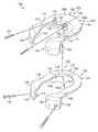
- FIG. 4is a side exploded elevation view of a portion of a lumbar spine showing a first embodiment of an artificial intervertebral joint constructed according to the principles of the disclosure.
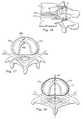
- FIG. 5is an anterior elevation view of a portion of a lumbar spine showing the superior, disc and inferior portions of the left and right halves of an assembled artificial intervertebral joint constructed according to the first embodiment of the disclosure.
- FIG. 6is a side elevation view of the right half of the artificial intervertebral joint shown in FIG. 5 .
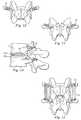
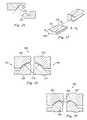
- FIG. 7Ais a transverse, bottom-up-view of a portion of a lumbar spine showing the superior portion of the artificial intervertebral joint illustrated in FIG. 4 .
- FIG. 7Bis a transverse, top-down-view of a portion of a lumbar spine showing the inferior portion of the artificial intervertebral joint illustrated in FIG. 4 .
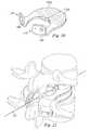
- FIG. 8is a transverse, bottom-up-view of a portion of a lumbar spine showing a second embodiment of a superior portion of an artificial intervertebral joint in which pedicle screws are used to assist in implantation.
- FIG. 9is a transverse, top-down-view of a portion of a lumbar spine showing a second embodiment of an inferior portion of an artificial intervertebral joint in which pedicle screws are used to assist in implantation.
- FIG. 10is a lateral view of a portion of a lumbar spine showing the superior portion of the artificial intervertebral joint shown in FIG. 8 with one of the pedicle screws being visible.
- FIG. 11is a lateral view of a portion of a lumbar spine showing the inferior and integrated disc portions of an artificial integral intervertebral joint shown in FIG. 9 with one of the pedicle screws being visible.
- FIG. 12is a posterior view of a portion of a lumbar spine showing the superior portion of the artificial intervertebral joint shown in FIG. 8 with two pedicle screws being visible.
- FIG. 13is a posterior view of a portion of a lumbar spine showing the inferior portion of the artificial intervertebral joint shown in FIG. 9 with two pedicle screws being visible.
- FIG. 14is a side elevation view of a portion of a lumbar spine showing the second embodiment with pedicle screws in an assembled position.
- FIG. 15is a posterior view of a portion of a lumbar spine showing a third embodiment of the inferior, disc and superior portions of an artificial intervertebral joint in which tension bands are used.
- FIG. 16is a side elevation view of a portion of a lumbar spine showing the third embodiment in which tension bands are used in an assembled position.
- FIG. 17is a transverse, bottom-up-view of a portion of a lumbar spine showing the superior portion of a fourth embodiment of an artificial intervertebral joint constructed according to the principles of the disclosure in which the facet joints are not replaced.
- FIG. 18is a transverse, top-down-view of a portion of a lumbar spine showing the inferior portion of the fourth embodiment of an artificial intervertebral joint.
- FIG. 19is an exploded perspective view of another embodiment of the present disclosure.
- FIG. 20is a second perspective view of the embodiment of FIG. 19 .
- FIG. 21is a third perspective view of the embodiment of FIG. 19 .
- FIG. 22is a top view of another embodiment of the present disclosure.
- FIG. 23is a cross-sectional view of the embodiment of FIG. 22 .
- FIG. 24is a cross sectional view of another embodiment of the present disclosure.
- FIG. 25is a top view of another embodiment of the present disclosure.
- FIG. 26is a cross-sectional view of another embodiment of the present disclosure.
- FIG. 27is a perspective view of another embodiment of the present disclosure.
- FIG. 28is a cross-sectional view of another embodiment of the present disclosure.
- FIG. 29is a cross-sectional view of another embodiment of the present disclosure.
- FIG. 1illustrate various embodiments of an artificial intervertebral joint for replacing an intervertebral disc or the combination of an intervertebral disc and at least one corresponding facet joint.
- Various embodiments of the artificial intervertebral joint according to the principles of the disclosuremay be used for treating any of the problems that lend themselves to joint replacement including particularly, for example, degenerative changes of the lumbar spine, post-traumatic, discogenic, facet pain or spondylolisthesis and/or to maintain motion in multiple levels of the lumbar spine.
- FIGS. 4-7illustrate a first exemplary embodiment of an artificial intervertebral joint.
- each jointis composed of two arthroplasty halves, each of which has a spacer or disc 19 and a retaining portion 21 .
- the retaining portion 21includes a first retaining portion 21 a and a second retaining portion 21 b .
- the first retaining portion 21 ais superior to (above) the second retaining portion 21 b and the disc 19 is situated therebetween.
- the artificial intervertebral jointhas two halves for each of the first retaining portion and the second retaining portion
- alternative embodimentsmay be implemented such that the artificial intervertebral joint has a single first retaining member, a single second retaining member and a single spacer.
- alternative embodimentsmay also be carried out with arthroplasties having a first retaining portion, a second retaining portion, and/or a disc which each consist of unequal sized halves or more than two components.
- the first retaining portion 21 a and the second retaining portion 21 bare situated between two adjacent vertebrae. More particularly, the first retaining portion may be situated along an inferior surface of the upper of the two adjacent vertebrae and the second retaining portion may be situated above a superior surface of the lower of the two adjacent vertebrae.
- the first retaining portion and second retaining portionare not limited to such an arrangement, and may be oriented in different positions and/or shaped differently than what is illustrated herein.
- the surfaces of the retaining portions 21 a , 21 b of the arthroplasty that contact the remaining end plates of the vertebraemay be coated with a beaded material or plasma sprayed to promote bony ingrowth and a firm connection therebetween.
- the surface to promote bone ingrowthmay be a cobalt chromium molybdenum alloy with a titanium/calcium/phosphate double coating, a mesh surface, or any other effective surface finish.
- an adhesive or cementsuch as polymethylmethacrylate (PMMA) may be used to fix all or a portion of the implants to one or both of the endplates.
- PMMApolymethylmethacrylate
- a significant portion of the outer annulus region 17may be retained on the inferior portion of the end plate, which acts as a stop retaining the lower retaining portions in place until bone ingrowth occurs to firmly attach the retaining portions to their respective vertebrae ( FIG. 4 only shows a portion of the outer annulus 17 that is retained).
- FIG. 4only shows a portion of the outer annulus 17 that is retained.
- pedicle screwsmay also be used for immediate fixation as described in more detail in connection with other embodiments discussed below.
- the first retaining portion 21 a and the second retaining portion 21 bare structured so as to retain the disc 19 therebetween.
- each of the first retaining portion 21 a and the second retaining portion 21 bmay have a concave surface 21 c which defines a space within which the disc 19 may be retained.
- FIG. 1In the exemplary embodiment shown in FIG. 1
- the upper convex surface 19 a of the disc 19fits within the concavity defined by the concave surface 21 c of the first retaining portion 21 a and the lower convex surface 19 b of the disc 19 fits within the concavity defined by the concave surface 21 c of the second retaining portion 21 b.
- FIG. 5illustrates an anterior view of an exemplary assembled artificial intervertebral joint with both arthroplasty halves in place
- FIG. 6shows a side view of the assembled artificial intervertebral joint shown in FIG. 5
- the disc 19is retained between the first retaining portion 21 a and the second retaining portion 21 b . It should be understood that although the disc 19 may be held between the first retaining portion 21 a and the second retaining portion 21 b , the disc 19 is free to slidably move within the space defined by the corresponding surfaces 21 a of the first retaining portion 21 a and the second retaining portion 21 b . In this manner, limited movement between the adjacent vertebrae is provided.
- the disc 19is a separate component which is inserted between the first retaining portion 21 a and the second retaining portion 21 b .
- the spacer or disc 19may be integrally formed with or integrated into in one or both of the first retaining portion 21 a and the second retaining portion 21 b.
- each of the retaining portions of the artificial intervertebral jointincludes a first artificial facet component 23 a and a second artificial facet component 23 b .
- the first artificial facet component 23 ahas a face 25 a
- the corresponding second artificial facet component 23 bhas a face 25 b configured such that the face 25 a matingly fits with the face 25 b to stabilize adjacent vertebrae while preserving and guiding the mobility of each vertebrae with respect to the other vertebrae.
- Each set of the upper and lower retaining portions 21 a , 21 bmay have a pair of facet components 23 a , 23 b , which together define a facet joint.
- the left and right arthroplastieswould define two adjacent facet joints when viewed from the posterior.
- the respective upper and lower retaining portions associated with the left and right halves of the arthroplastymay be completely independent from the other. That is, as shown in FIG. 7A , for example, the first retaining portions 21 a associated with each half are not in direct contact with each other. The same is true with respect to the second retaining portions 21 b shown in FIG. 7B .
- the first retaining portions 21 a of each half and/or at least a portion of the second retaining portions 21 b of each halfmay directly contact and/or be connected to each other as described in more detail in connection with the discussion of FIGS. 17-18 .
- the disc 19 , the first retaining portion 21 a and the second retaining portion 21 bmay be made of any appropriate material which will facilitate a connection that transmits compressive and tensile forces while providing for the aforementioned slidable motion in a generally transverse direction between each of the adjacent surfaces.
- the first retaining portion 21 a and the second retaining portion 21 bmay be typically made from any metal or metal alloy suitable for surgical implants such as stainless steel, titanium, and cobalt chromium, or composite materials such as carbon fiber, or a plastic material such as polyetheretherketone (PEEK) or any other suitable materials.
- the discmay be made from plastic such as high molecular weight polyethylene or PEEK, or from ceramics, metal, and natural or synthetic fibers such as, but not limited to, carbon fiber, rubber, or other suitable materials.
- plasticsuch as high molecular weight polyethylene or PEEK
- ceramicssuch as, but not limited to, carbon fiber, rubber, or other suitable materials.
- the surfacesmay be polished and/or coated to provide smooth surfaces.
- the metal surfacesmay be polished metal.
- FIGS. 8-14illustrate a second embodiment of an artificial intervertebral joint. Only features that differ from the first embodiment are discussed in detail herein.
- securing componentssuch as, for example, pedicle screws 27 are provided to provide a more secure and immediate connection between each of the first retaining portion 21 a and/or the second retaining portion 21 b to the corresponding vertebra.
- this embodimentillustrates a disc 19 which is integrated with one of the retaining portions, here lower retaining portion 21 b .
- Disc 19may be integrally formed from the same material as its retaining portion, but also may be separately formed from similar or dissimilar materials and permanently connected thereto to form an integral unit.
- the disc 19 and the retaining portionsmay be all formed from metal.
- FIGS. 15 and 16illustrate a third embodiment of an artificial intervertebral joint.
- additional securing componentssuch as, for example, tension bands 31 are provided to supplement or replace the function of posterior ligaments that limit the mobility between adjacent vertebrae by securing the first retaining portion 21 a to the second retaining portion 21 b .
- posterior tension bands 31may be provided by wrapping them around the corresponding pedicle screws 27 or other convenient attachment points.
- FIGS. 17 and 18illustrate a fourth embodiment of an artificial intervertebral joint.
- the artificial intervertebral jointmay have all of the features discussed above except for artificial facet components.
- the natural facet jointsremain.
- the ligamentous tension bandmay also be left intact in some embodiments.
- this embodimentincludes a specific example of an anterior midline connection between respective upper and lower retaining portions, which assists in maintaining the placement of the first retaining portion 21 a and the second retaining portion 21 b.
- FIGS. 17 and 18illustrate that it is possible to provide a first retaining portion 21 a with a lock and key type pattern which is complemented by the corresponding mating portion provided on the second retaining portion 21 b . More particularly, one half of the first retaining portion 21 a has an outer boundary with a U-shaped portion 35 a while the other half of the corresponding first retaining portion 21 a has an outer boundary with a protruding portion 35 b , which fits into the U-shaped portion 35 a . As a result, each half of the first retaining portion 21 a , 21 b may be maintained in a predetermined position.
- the upper or lower retaining portionsmay fit together and/or be connected in the interbody space, e.g., near their midline anterior portions, in any manner that facilitates implantation and/or assists in providing and/or retaining the joint in a generally stable, symmetrical configuration. It may be even more important to provide such connection between the lower retaining portions due to the inward forces provided by annulus 17 remaining on the inferior end plate as shown in FIG. 18 . A midline connection between the respective lower retaining portions will resist the force of the outer annulus tending to cause migration of the retaining portions toward the midline 37 .
- each half of the artificial intervertebral jointmay be generally symmetrical about the midline 37 of the vertebrae.
- the halves of the artificial intervertebral jointmay be inserted piecewise through the left and right transforaminal openings, respectively. That is, the pieces of the artificial intervertebral joint including the upper and lower retaining portions, with or without facet components, and the artificial disc, if provided separately, fit through the foramina and are placed in the appropriate intervertebral space.
- the pieces of the artificial jointmay be completely separated or two or more of them may be tied or packaged together prior to insertion through the foramina by cloth or other materials known in the art.
- the lower retaining portions of each side of the artificial intervertebral jointare inserted such that they abut a corresponding portion of the annulus. If a midline anterior connection is provided, the left and right halves of the retaining members are fitted together and held in place by the outer annulus. As such, the remaining portion of the annulus may be in substantially the same place as it was prior to the procedure.
- the embodiment of the disclosurewhere the pedicle screws are implemented so as to be assured that the pieces of the artificial intervertebral joint remain in place.
- the artificial jointcould be implanted via an anterior approach or a combined anterior and posterior approach, although the advantages of a posterior procedure would be limited.
- some of the pieces of the artificial intervertebral jointmay be inserted from an anterior approach and others posteriorly.
- the anteriorly and posteriorly placed portionscould be fitted together similar to the embodiment shown in FIGS. 17 and 18 .
- an artificial intervertebral joint 100may include two arthroplasty halves 102 , 104 which may be inserted between the vertebrae 7 , 9 .
- the arthroplasty half 102may be an articulating joint replacement assembly and may include a rostral anterior component 106 , a rostral posterior joint component 108 , and a rostral bridge 110 extending between the anterior component 106 and the posterior component 108 .
- the rostral anterior component 106may further include an interlocking wall 107 .
- the arthroplasty half 102may further include a caudal anterior joint component 112 , a caudal posterior joint component 114 , and a caudal bridge 116 extending between the anterior component 112 and the posterior component 114 .
- the caudal anterior component 112may further include an interlocking wall 115 .
- the rostral anterior joint component 106may include a bone contacting surface 106 a
- the caudal anterior joint component 112may include a bone contacting surface 112 a.
- rostral and caudalare used in some embodiments to describe the position of components of the embodiments. While rostral is typically used in the art to describe positions toward the head and caudal is used to describe positions toward the tail or foot, as used herein, rostral and caudal are used simply as modifiers for the relative locations of components of the illustrated embodiments. For example, rostral components may be on one side of an illustrated joint, and caudal may be on another side of the joint. Components labeled as rostral or caudal to describe an illustrated embodiment are not intended to limit the orientation of a device or application of a method relative to a patient's anatomy, or to limit the scope of claims to any device or method.
- the rostral bridge 110may include a jog 117 to create an exit portal and an artificial foramen for the exiting nerve root. Either of the bridges 110 , 116 , but particularly the caudal bridge 116 , may be a “super” or artificial pedicle which may supplement or replace a natural pedicle.
- the caudal anterior joint component 112may include a caudal articulating surface such as a curved protrusion 118
- the caudal posterior joint component 114may include a posterior articulating portion 120 .
- the rostral anterior joint component 106may include a rostral articulating surface such as an anterior socket 122 configured to receive the curved protrusion 118 .
- a radius of curvature for the curved protrusion 118may closely match the radius of curvature for the anterior socket 122 to create a highly constrained ball and socket type engagement.
- the curved protrusionmay be permitted to translate within the socket.
- the rostral posterior joint component 108may include a posterior socket 124 configured to engage the posterior articulating portion 120 .
- a radius of curvature for the posterior articulating portion 120may be smaller than a radius of curvature for the posterior socket 124 , thereby permitting motion and limiting binding between the posterior joint components 108 , 114 .
- the radii of curvature for the posterior socket 124 and the posterior articulating portion 120may emanate from a common center of rotation for the arthroplasty half 102 .
- the radius of curvature for the posterior socket 124is relatively large, and the resulting joint is loosely constrained.
- a tight radius of curvature for the posterior protrusion of the caudal posterior component matched with a rostral posterior component having a tight radius of curvaturemay create a tightly constrained posterior joint.
- the arthroplasty half 104may be an articulating joint replacement assembly and may include a rostral anterior joint component 146 , a rostral posterior joint component 148 , and a rostral bridge 150 extending between the anterior component 146 and the posterior component 148 .
- the rostral anterior component 146may further include an interlocking wall 147 .
- the arthroplasty half 104may further include a caudal anterior joint component 152 , a caudal posterior joint component 154 , and a caudal bridge 156 extending between the anterior component 152 and the posterior component 154 .
- the caudal anterior component 152may further include an interlocking wall 155 .
- the rostral anterior joint component 146may include a bone contacting surface 146 a and the caudal anterior joint component 152 may include a bone contacting surface 152 a.
- the rostral bridge 150may include a jog 157 to create an exit portal and an artificial foramen for the exiting nerve root.
- the caudal anterior joint component 152may include a caudal articulating surface such as a curved protrusion 158 .
- the rostral anterior joint component 146may include a rostral articulating surface such as an anterior socket 171 configured to receive the curved protrusion 158 .
- a radius of curvature for the curved protrusion 158may closely match the radius of curvature for the anterior socket 171 to create a highly constrained ball and socket type engagement.
- the curved protrusionmay be permitted to translate within the socket.
- the caudal posterior joint component 154may include a posterior articulating portion 160 .
- the rostral posterior joint component 148may include a posterior socket 162 configured to engage the posterior articulating portion 160 .
- a radius of curvature for the posterior articulating portion 160may be smaller than a radius of curvature for the posterior socket 162 , thereby permitting motion and limiting binding between the posterior joint components 148 , 154 .
- the radii of curvature for the posterior socket 162 and the posterior articulating portion 160may emanate from a common center of rotation for the arthroplasty half 104 .
- the radius of curvature for the posterior socket 162is relatively large, and the resulting joint is loosely constrained.
- a tight radius of curvature for the posterior protrusion of the caudal posterior component matched with a rostral posterior component having a tight radius of curvaturemay create a tightly constrained posterior joint.
- the size and shape of the anterior components 106 , 112 , 146 , 152 and the bridge components 110 , 116 , 150 , 156may be limited by the constraints of a posterior or transforaminal surgical approach.
- the anterior components 106 , 112 , 146 , 152may be configured to cover a maximum vertebral endplate area to dissipate loads and reduce subsidence while still fitting through the posterior surgical exposure, Kambin's triangle, and other neural elements.
- the width of the bridge components 110 , 116 , 150 , 156are also minimized to pass through Kambin's triangle and to co-exist with the neural elements.
- the arthroplasty halves 102 , 104may further includes features for securing to the vertebrae 7 , 9 . It is understood, however, that in an alternative embodiment, the fixation features may be eliminated.
- the arthroplasty half 104may include fixation features substantially similar to arthroplasty half 102 and therefore will not be described in detail.
- the arthroplasty half 102may include a connection component 170 extending rostrally from the rostral anterior joint component 106 .
- the connection component 170 in this embodimentincludes an aperture adapted to receive a bone fastener such as a screw 172 .
- the orientation of the connection component 170permits interbody fixation of the screw 172 to the cylindrical vertebral body 7 a.
- Arthroplasty half 102may further include a connection component 174 attached to or integrally formed with the caudal posterior joint component 114 .
- the connection component 174 in this embodimentincludes an aperture adapted to receive a bone fastener such as a screw 176 .
- the orientation of the connection component 174permits the screw 176 to become inserted extrapedicularly such that the screw travels a path angled or skewed away from a central axis defined through a pedicle.
- Extrapedicular fixationmay be any fixation into the pedicle that does not follow a path down a central axis defined generally posterior-anterior through the pedicle.
- the screwpasses through a lateral wall of the pedicle and may achieve strong cortical fixation.
- the screwsmay be recessed so as not to interfere with articulations, soft tissues, and neural structures.
- a connection component extending from the posterior component 114may be oriented to permit the screw to become inserted intrapedicularly such that the screw travels a path generally along the central axis through the pedicle.
- the posterior connection componentmay connect to the generally cylindrical body portion 9 a .
- the connection componentsmay extend at a variety of angles, in a variety of directions from the various components of the arthroplasty half.
- a connection componentmay extend from the rostral bridge rather than the rostral anterior joint component.
- the rostral components 106 , 108 , 110 of the articulating joint replacement assembly 102are integrally formed with rigid connections between the components. It is understood that in a modular alternative embodiment, these components may be removably coupled to one another.
- the rostral anterior joint componentmay be installed separate from the bridge. After the anterior component is in place, the bridge may be attached to the anterior component by any fastening mechanism known in the art, for example a threaded connection, a bolted connection, or a latched connection.
- a modular rostral posterior componentmay then be attached by a similar fastening mechanism to the bridge to complete the rostral portion of the arthroplasty half.
- the caudal componentsmay be modular.
- the arthroplasty halves 102 , 104may be formed of any suitable biocompatible material including metals such as cobalt-chromium alloys, titanium alloys, nickel titanium alloys, and/or stainless steel alloys. Ceramic materials such as aluminum oxide or alumina, zirconium oxide or zirconia, compact of particulate diamond, and/or pyrolytic carbon may also be suitable.
- Polymer materialsmay also be used, including any member of the polyaryletherketone (PAEK) family such as polyetheretherketone (PEEK), carbon-reinforced PEEK, or polyetherketoneketone (PEKK); polysulfone; polyetherimide; polyimide; ultra-high molecular weight polyethylene (UHMWPE); and/or cross-linked UHMWPE.
- PAEKpolyaryletherketone
- PEEKpolyetheretherketone
- PEKKpolyetherketoneketone
- polysulfonepolyetherimide
- polyimidepolyimide
- UHMWPEultra-high molecular weight polyethylene
- UHMWPEultra-high molecular weight polyethylene
- the various components comprising the arthroplasty halves 102 , 104may be formed of different materials thus permitting metal on metal, metal on ceramic, metal on polymer, ceramic on ceramic, ceramic on polymer, or polymer on polymer constructions.
- Bone contacting surfaces of the arthroplasty halves 102 , 104may include features or coatings which enhance the fixation of the implanted prosthesis.
- the surfacesmay be roughened such as by chemical etching, bead-blasting, sanding, grinding, serrating, and/or diamond-cutting. All or a portion of the bone contacting surfaces of the arthroplasty halves 102 , 104 may also be coated with a biocompatible and osteoconductive material such as hydroxyapatite (HA), tricalcium phosphate (TCP), and/or calcium carbonate to promote bone in growth and fixation.
- HAhydroxyapatite
- TCPtricalcium phosphate
- osteoinductive coatingssuch as proteins from transforming growth factor (TGF) beta superfamily, or bone-morphogenic proteins, such as BMP 2 or BMP 7 , may be used.
- TGFtransforming growth factor
- BMP 2 or BMP 7bone-morphogenic proteins
- suitable featuresmay include spikes, ridges, and/or other surface textures.
- the artificial intervertebral joint 100may be installed between the vertebrae 7 , 9 as will be described below using a bilateral delivery.
- the artificial intervertebral joint 100may be implanted into a body using a posterior transforaminal approach similar to the known TLIF or PLIF procedures.
- PLIF approachesare generally more medial and rely on more retraction of the traversing root and dura to access the vertebral interspace. The space between these structures is known as Kambin's triangle.
- TLIF approachesare typically more oblique, requiring less retraction of the exiting root, and less epidural bleeding with less retraction of the traversing structures.
- an incisionsuch as a midline incision, may be made in the patient's back and some or all of the affected disc and surrounding tissue may be removed via the foramina.
- the superior endplate surface of the vertebra 9may be milled, rasped, or otherwise resected to match the profile of the caudal anterior bone contacting surface 112 a , to normalize stress distributions on the superior endplate surface of the vertebra 9 , and/or to provide initial fixation prior to bone ingrowth.
- the preparation of the endplate of vertebra 9may result in a flattened surface or in surface contours such as pockets, grooves, or other contours that may match corresponding features on the bone contacting surface 112 a .
- the inferior endplate of the vertebra 7may be similarly prepared to receive the rostral anterior joint component 106 to the extent allowed by the exiting nerve root and the dorsal root ganglia. Depending on whether any of the facet joints are being replaced, the natural facet joints of vertebrae 7 , 9 may be trimmed to make room for the posterior components 108 , 114 .
- the articulating joint replacement assembly 102 of the artificial intervertebral joint 100may then be inserted piecewise through, for example, the left transforaminal exposure. That is, the pieces of the articulating joint replacement assembly 102 including the rostral and caudal anterior joint components 106 , 112 respectively are fit through the foramina and are placed in the appropriate intervertebral disc space between the generally cylindrical bodies 7 a , 9 a .
- the anterior joint components 106 , 112may be delivered along a curved path similar to that used in a “kidney bean” TLIF graft.
- the anterior joint components 106 , 112may be positioned such that the anterior socket 122 is engaged with the curved protrusion 118 to form one lateral half of a single, unitized ball and socket style joint.
- the joint formed by the anterior socket 122 and the curved protrusion 118may abut a central anterior-posterior axis 127 through the intervertebral disc space.
- the anterior articulation provided by the anterior socket 122 engaged with the curved protrusion 118may be completed with unilateral delivery. If the articulating joint replacement assembly 104 cannot be inserted, the articulating joint replacement assembly 102 may function on its own.
- the pieces of the articulating joint replacement assembly 102may be completely separated or two or more of them may be tied or packaged together prior to insertion through the foramina by cloth or other materials known in the art.
- the caudal anterior joint componentsmay be inserted such that they abut a corresponding portion of the annulus.
- the bridges 110 , 116may extend posteriorly from the anterior joint components 106 , 112 , respectively and posteriorly from the intervertebral disc space.
- the posterior components 108 , 114may be positioned posteriorly of the intervertebral disc space with the posterior socket 124 engaged with the posterior articulating portion 120 .
- These posterior components 108 , 114may replace or supplement the function of the natural facet joints. Similar positioning may be completed for the components of the arthroplasty half 104 .
- the bridges 110 , 116 , 150 , 156may serve to prevent subsidence.
- the articulating joint replacement assembly 104 of the artificial intervertebral joint 100may then be inserted piecewise through a contralateral exposure, for example, a right transforaminal exposure. That is, the pieces of the articulating joint replacement assembly 104 including the rostral and caudal anterior joint components 146 , 152 respectively fit through the contralateral foramina and are placed in the appropriate intervertebral disc space between the generally cylindrical bodies 7 a , 9 a .
- the anterior joint components 146 , 152may also be delivered along a curved path similar to that used in a “kidney bean” TLIF graft or any other path that accommodates the shape of the components.
- the pieces of the articulating joint replacement assembly 104may be completely separated or two or more of them may be tied or packaged together prior to insertion through the foramina by cloth or other materials known in the art.
- the anterior joint components 146 , 152may be positioned such that the anterior socket 171 is engaged with the curved protrusion 158 to form one lateral half of a single, unitized ball and socket style joint.
- the joint formed by the anterior socket 171 and the curved protrusion 158may abut the central anterior-posterior axis 127 through the intervertebral disc space.
- the anterior joint components 146 , 152may be connected to the anterior joint components 106 , 112 , respectively.
- the interlocking wall 115 of the caudal anterior joint component 112may be placed into engagement with the interlocking wall 155 of the caudal anterior joint component 152 .
- Curved protrusion 118may thus become connected to curved protrusion 158 , which in this embodiment may result in the formation of single kidney-shaped protrusion centered about the axis 127 .
- the rostral anterior joint component 106may be similarly positioned with respect to the rostral anterior joint component 146 , with the interlocking wall 122 engaged with the interlocking wall 147 .
- Anterior socket 122may thus become connected to anterior socket 171 , which in this embodiment may result in the formation of a single kidney-shaped recess centered about the axis 127 . All together, the joint formed by the anterior socket 122 with the curved protrusion 118 and the joint formed by the anterior socket 171 with the curved protrusion 158 form a single unitized intervertebral joint centered about the axis 127 .
- This single unitized intervertebral jointmay allow for a common center of rotation for the various components of the artificial joint 100 , including the posterior joints.
- the various articulating surfaces of the joint 100may be formed by concentric spheres, such that motions in both the anterior joint and the posterior joints occur about a common point.
- only the rostral joint componentsmay be connected.
- only the caudal joint componentsmay be connected.
- the contralateral exposuremay be abandoned if problems occur during the surgery.
- the arthroplastymay be completed with the unilateral delivery of only the articulating joint replacement assembly 102 .
- the bridges 150 , 156may extend posteriorly from the anterior joint components 146 , 152 and posteriorly from the intervertebral disc space.
- the posterior components 148 , 154may be positioned posteriorly of the intervertebral disc space with the posterior socket 162 engaged with the posterior articulating portion 160 . These posterior components 148 , 154 may replace or supplement the function of the natural facet joints.
- the articulating joint replacement assembly 102 and the articulating joint replacement assembly 104may be secured to vertebrae 7 , 9 .
- the screw 172may be inserted through the connection component 170 and into the generally cylindrical body 7 a .
- the screw 176may be inserted through the connection component 174 and may be affixed extrapedicularly to the vertebra 9 , for example, the screw 176 may pass through a lateral wall of the pedicle to achieve strong cortical fixation.
- Corresponding fastenersmay be used to secure the articulating joint replacement assembly 104 . It is understood that the screws may be implanted either after the entire arthroplasty half has been implanted or after each of the rostral and caudal component has been implanted.
- the unitized anterior ball and socket type joint created by the anterior joint components 106 , 112 , 146 , 152may be relatively stable and self-centering. Both the anterior and the posterior joints allow the arthroplasty halves 102 , 104 to resist shear forces, particularly anterior-posterior forces. Movement of the rostral anterior joint component 106 relative to the caudal anterior joint component 112 may be limited by the displacement of the posterior articulating portion 120 within the posterior socket 124 . For example, lateral translation of the rostral anterior joint component 106 relative to the caudal anterior joint component 112 may be limited by the posterior joint. Similar constraints may arise in the arthroplasty half 104 .
- Rotational motion about a longitudinal axis defined by the cylindrical bodies 7 a , 9 amay be limited both by the constraint in the posterior joints and by the combined constraint provided by the two arthroplasty halves 102 , 104 . Further, the posterior joints may restrict any true lateral bending degree of freedom.
- Pure freedom of motionmay be limited to flexion-extension motion about an axis defined through the anterior joints of the articulating joint replacement assemblies 102 , 104 .
- the joint 100may overcome these design restrictions to permit limited lateral, rotational, and coupled movements.
- the anterior joint components 106 , 112may become disconnected from each other and experience limited “lift-off,” thereby permitting additional degrees of freedom and coupled motions beyond strict flexion-extension motion.
- the self-centering nature of the anterior jointmay encourage reconnection and alignment after lift-off occurs.
- the limited disconnection of the anterior joint components 106 , 112may be accommodated by the degree of constraint in the posterior joint.
- relatively loose constraint in the posterior jointpermits greater amounts of lift-off.
- Some degree of constraint in the posterior jointmay be useful, however, to encourage reconnection and alignment of the anterior joint.
- a simple, anteriorly located ball and socket jointwhich is tightly constrained with each component having the same or similar radii of curvature may allow flexion-extension, lateral bending, and torsion motions while resisting shear forces and limiting translation.
- an additional degree of freedommay be limited, such as torsion.
- Additional jointsmay further limit degrees of freedom of motion. If the anterior or posterior joints are permitted to disconnect or disarticulate additional degrees of freedom may be permitted as described above. Changing the shape of or clearance between the ball and socket components will also permit additional degrees of motion.
- an artificial intervertebral jointmay be substantially similar to artificial intervertebral joint 100 except for the differences described below.
- a caudal anterior joint component 202may include an interlocking wall 204
- a caudal anterior joint component 206may include an interlocking wall 208 .
- the interlocking wall 204may include a connection mechanism 210
- the interlocking wall 206may include a connection mechanism 212 .
- the connection mechanism 210is a female component of a dove-tail connection
- the connection mechanism 212is a male component of a dove-tail connection.
- a lap joint locking mechanismmay interlock the anterior joint components.
- a female component 214 of a lap joint locking mechanismmay interlock with a male component 216 of the lap joint locking mechanism.
- a connecting mechanism 218may include a curved, interlocking wall 220 and a curved interlocking wall 222 . Similar connections may be provided for rostral anterior components.
- a semi-cylindrical locking mechanismmay interlock the anterior joint components.
- a female component 250 of the semi-cylindrical locking mechanismmay interlock with a male component 252 of the semi-cylindrical locking mechanism.
- a tapered cylindrical locking mechanismmay interlock the anterior joint components.
- a male component 254 of the tapered cylindrical locking mechanismmay have a diameter 256 at a distal end and a diameter 258 at a proximal end, wherein the proximal diameter 258 is larger than the distal diameter 256 and the component 254 tapers from the proximal to the distal end.
- the described connection mechanismsare merely examples, and any other type of mechanical or adhesive connecting mechanisms known in the art may be used as the connecting mechanism.
- a caudal posterior joint componentmay include a connection component such as a round aperture.
- a rostral posterior joint componentmay include a connection component, such as an elongated aperture or slot.
- a bone fastenersuch as a bone screw with a bushing, may be inserted through the elongated aperture and the round aperture and into the vertebra. The fastener may be allowed to translate within the elongated aperture. Accordingly, the anterior articulating joint replacement components may be permitted to articulate in a limited flexion-extension motion as the fastener translates within the elongated aperture.
- an artificial intervertebral joint 260may include arthroplasty halves 262 , 264 .
- the arthroplasty half 262may include a rostal anterior component 266 and a caudal anterior component 268 .
- the arthroplasty half 264may include a rostral anterior component 270 and a caudal anterior component 272 .
- the joint 260may be substantially similar to the joint 100 except that the rostal components 266 , 270 may be unconnected.
- the caudal components 268 , 272may be unconnected and spaced slightly apart.
- the caudal anterior components 268 , 272may have a common center of curvature such that the caudal components behave as a unitized bearing.
- an artificial intervertebral joint 280may be substantially similar to the joint 260 except that rostral components 282 , 284 may include retaining features 286 , 288 , respectively.
- the retaining features 286 , 288may prevent lateral disarticulation of the caudal components.
- any of the artificial intervertebral joints described abovemay further include a rostral keel extending from the rostral anterior component and/or a caudal keel extending from the caudal anterior joint component and along the caudal bridge.
- the rostral keelmay engage the inferior endplate of the vertebral body 7 a
- the caudal keelmay engage the superior endplate of the vertebral body 9 a and a superior face of a pedicle of vertebra 9 . It is understood that the inferior endplate of the body 7 a may be milled or otherwise prepared to receive the rostral keel.
- the superior endplate of the body 9 a and the pedicle of vertebra 9may be milled, chiseled, or otherwise prepared to create a channel for receiving the caudal keel.
- the keelsmay help to connect to the bone and limit movement of the arthroplasty half to the desired degrees to freedom.
- the keelsmay have an angled or semi-cylindrical cross section. It is understood that more than one keel may be used on any given component.
Landscapes
- Health & Medical Sciences (AREA)
- Engineering & Computer Science (AREA)
- Biomedical Technology (AREA)
- Orthopedic Medicine & Surgery (AREA)
- Neurology (AREA)
- Heart & Thoracic Surgery (AREA)
- Oral & Maxillofacial Surgery (AREA)
- Transplantation (AREA)
- Cardiology (AREA)
- Vascular Medicine (AREA)
- Life Sciences & Earth Sciences (AREA)
- Animal Behavior & Ethology (AREA)
- General Health & Medical Sciences (AREA)
- Public Health (AREA)
- Veterinary Medicine (AREA)
- Prostheses (AREA)
Abstract
Description
- U.S. Utility patent application Ser. No. 11/031,602, filed on Jan. 7, 2005 and entitled “Spinal Arthroplasty Device and Method;”
- U.S. Utility patent application Ser. No. 11/031,603, filed on Jan. 7, 2005 and entitled “Dual Articulating Spinal Device and Method;”
- U.S. Utility patent application Ser. No. 11/031,904, filed on Jan. 7, 2005 and entitled “Interconnected Spinal Device and Method;”
- U.S. Utility patent application Ser. No. 11/031,783, filed on Jan. 7, 2005 and entitled “Mobile Bearing Spinal Device and Method;”
- U.S. Utility patent application Ser. No. 11/031,700, filed on Jan. 7, 2005 and entitled “Support Structure Device and Method;”
- U.S. Utility patent application Ser. No. 11/031,781, filed on Jan. 7, 2005 and entitled “Centrally Articulating Spinal Device and Method;” and
- U.S. Utility patent application Ser. No. 11/031,903, filed on Jan. 7, 2005 and entitled “Posterior Spinal Device and Method.”
Claims (46)
Priority Applications (2)
| Application Number | Priority Date | Filing Date | Title |
|---|---|---|---|
| US11/031,780US7901459B2 (en) | 2004-01-09 | 2005-01-07 | Split spinal device and method |
| PCT/US2005/000648WO2005067824A1 (en) | 2004-01-09 | 2005-01-10 | Split spinal device and method |
Applications Claiming Priority (2)
| Application Number | Priority Date | Filing Date | Title |
|---|---|---|---|
| US53496004P | 2004-01-09 | 2004-01-09 | |
| US11/031,780US7901459B2 (en) | 2004-01-09 | 2005-01-07 | Split spinal device and method |
Publications (2)
| Publication Number | Publication Date |
|---|---|
| US20050154465A1 US20050154465A1 (en) | 2005-07-14 |
| US7901459B2true US7901459B2 (en) | 2011-03-08 |
Family
ID=35149045
Family Applications (1)
| Application Number | Title | Priority Date | Filing Date |
|---|---|---|---|
| US11/031,780Active2028-05-11US7901459B2 (en) | 2004-01-09 | 2005-01-07 | Split spinal device and method |
Country Status (2)
| Country | Link |
|---|---|
| US (1) | US7901459B2 (en) |
| WO (1) | WO2005067824A1 (en) |
Cited By (42)
| Publication number | Priority date | Publication date | Assignee | Title |
|---|---|---|---|---|
| US8394129B2 (en) | 2011-03-10 | 2013-03-12 | Interventional Spine, Inc. | Method and apparatus for minimally invasive insertion of intervertebral implants |
| US8518087B2 (en) | 2011-03-10 | 2013-08-27 | Interventional Spine, Inc. | Method and apparatus for minimally invasive insertion of intervertebral implants |
| US9277928B2 (en) | 2013-03-11 | 2016-03-08 | Interventional Spine, Inc. | Method and apparatus for minimally invasive insertion of intervertebral implants |
| USD753306S1 (en)* | 2014-02-10 | 2016-04-05 | Brian D. Burkinshaw | Spinal disc implant with conic protrusions |
| US9408711B2 (en) | 2013-03-14 | 2016-08-09 | Brian D. Burkinshaw | Unitary spinal disc implant |
| USD764666S1 (en)* | 2014-02-10 | 2016-08-23 | Brian D. Burkinshaw | Unitary spinal disc implant |
| US9522070B2 (en) | 2013-03-07 | 2016-12-20 | Interventional Spine, Inc. | Intervertebral implant |
| US9839530B2 (en) | 2007-06-26 | 2017-12-12 | DePuy Synthes Products, Inc. | Highly lordosed fusion cage |
| US9883951B2 (en) | 2012-08-30 | 2018-02-06 | Interventional Spine, Inc. | Artificial disc |
| US9895236B2 (en) | 2010-06-24 | 2018-02-20 | DePuy Synthes Products, Inc. | Enhanced cage insertion assembly |
| USD812227S1 (en)* | 2017-01-25 | 2018-03-06 | Brian D. Burkinshaw | Unitary spinal disc implant with a central core |
| US9913727B2 (en) | 2015-07-02 | 2018-03-13 | Medos International Sarl | Expandable implant |
| US9931223B2 (en) | 2008-04-05 | 2018-04-03 | DePuy Synthes Products, Inc. | Expandable intervertebral implant |
| US9968460B2 (en) | 2013-03-15 | 2018-05-15 | Medsmart Innovation Inc. | Dynamic spinal segment replacement |
| US9993353B2 (en) | 2013-03-14 | 2018-06-12 | DePuy Synthes Products, Inc. | Method and apparatus for minimally invasive insertion of intervertebral implants |
| US9993349B2 (en) | 2002-06-27 | 2018-06-12 | DePuy Synthes Products, Inc. | Intervertebral disc |
| US10058433B2 (en) | 2012-07-26 | 2018-08-28 | DePuy Synthes Products, Inc. | Expandable implant |
| US10335207B2 (en) | 2015-12-29 | 2019-07-02 | Nuvasive, Inc. | Spinous process plate fixation assembly |
| US10369015B2 (en) | 2010-09-23 | 2019-08-06 | DePuy Synthes Products, Inc. | Implant inserter having a laterally-extending dovetail engagement feature |
| USD857200S1 (en)* | 2018-01-19 | 2019-08-20 | Brian D. Burkinshaw | Unitary spinal disc implant |
| US10390963B2 (en) | 2006-12-07 | 2019-08-27 | DePuy Synthes Products, Inc. | Intervertebral implant |
| US10398563B2 (en) | 2017-05-08 | 2019-09-03 | Medos International Sarl | Expandable cage |
| US10433977B2 (en) | 2008-01-17 | 2019-10-08 | DePuy Synthes Products, Inc. | Expandable intervertebral implant and associated method of manufacturing the same |
| US10500062B2 (en) | 2009-12-10 | 2019-12-10 | DePuy Synthes Products, Inc. | Bellows-like expandable interbody fusion cage |
| US10537436B2 (en) | 2016-11-01 | 2020-01-21 | DePuy Synthes Products, Inc. | Curved expandable cage |
| US10548741B2 (en) | 2010-06-29 | 2020-02-04 | DePuy Synthes Products, Inc. | Distractible intervertebral implant |
| US10888433B2 (en) | 2016-12-14 | 2021-01-12 | DePuy Synthes Products, Inc. | Intervertebral implant inserter and related methods |
| US10940016B2 (en) | 2017-07-05 | 2021-03-09 | Medos International Sarl | Expandable intervertebral fusion cage |
| US11344424B2 (en) | 2017-06-14 | 2022-05-31 | Medos International Sarl | Expandable intervertebral implant and related methods |
| US11426286B2 (en) | 2020-03-06 | 2022-08-30 | Eit Emerging Implant Technologies Gmbh | Expandable intervertebral implant |
| US11426290B2 (en) | 2015-03-06 | 2022-08-30 | DePuy Synthes Products, Inc. | Expandable intervertebral implant, system, kit and method |
| US11446156B2 (en) | 2018-10-25 | 2022-09-20 | Medos International Sarl | Expandable intervertebral implant, inserter instrument, and related methods |
| US11452607B2 (en) | 2010-10-11 | 2022-09-27 | DePuy Synthes Products, Inc. | Expandable interspinous process spacer implant |
| US11510788B2 (en) | 2016-06-28 | 2022-11-29 | Eit Emerging Implant Technologies Gmbh | Expandable, angularly adjustable intervertebral cages |
| US11596523B2 (en) | 2016-06-28 | 2023-03-07 | Eit Emerging Implant Technologies Gmbh | Expandable and angularly adjustable articulating intervertebral cages |
| US11612491B2 (en) | 2009-03-30 | 2023-03-28 | DePuy Synthes Products, Inc. | Zero profile spinal fusion cage |
| US11752009B2 (en) | 2021-04-06 | 2023-09-12 | Medos International Sarl | Expandable intervertebral fusion cage |
| US11850160B2 (en) | 2021-03-26 | 2023-12-26 | Medos International Sarl | Expandable lordotic intervertebral fusion cage |
| US11911287B2 (en) | 2010-06-24 | 2024-02-27 | DePuy Synthes Products, Inc. | Lateral spondylolisthesis reduction cage |
| USRE49973E1 (en) | 2013-02-28 | 2024-05-21 | DePuy Synthes Products, Inc. | Expandable intervertebral implant, system, kit and method |
| US12090064B2 (en) | 2022-03-01 | 2024-09-17 | Medos International Sarl | Stabilization members for expandable intervertebral implants, and related systems and methods |
| US12440346B2 (en) | 2023-03-31 | 2025-10-14 | DePuy Synthes Products, Inc. | Expandable intervertebral implant |
Families Citing this family (80)
| Publication number | Priority date | Publication date | Assignee | Title |
|---|---|---|---|---|
| DE60139262D1 (en) | 2000-08-28 | 2009-08-27 | Disc Dynamics Inc | SYSTEM FOR RECONSTRUCTING JOINT SURFACES OF MAMMALS |
| AU2003265597A1 (en)* | 2002-08-23 | 2004-03-11 | Paul C. Mcafee | Metal-backed uhmpe rod sleeve system preserving spinal motion |
| US7753958B2 (en) | 2003-08-05 | 2010-07-13 | Gordon Charles R | Expandable intervertebral implant |
| US7909869B2 (en) | 2003-08-05 | 2011-03-22 | Flexuspine, Inc. | Artificial spinal unit assemblies |
| US7799082B2 (en) | 2003-08-05 | 2010-09-21 | Flexuspine, Inc. | Artificial functional spinal unit system and method for use |
| US7588590B2 (en) | 2003-12-10 | 2009-09-15 | Facet Solutions, Inc | Spinal facet implant with spherical implant apposition surface and bone bed and methods of use |
| US7875077B2 (en)* | 2004-01-09 | 2011-01-25 | Warsaw Orthopedic, Inc. | Support structure device and method |
| US7556651B2 (en)* | 2004-01-09 | 2009-07-07 | Warsaw Orthopedic, Inc. | Posterior spinal device and method |
| US20050171608A1 (en)* | 2004-01-09 | 2005-08-04 | Sdgi Holdings, Inc. | Centrally articulating spinal device and method |
| US20050154467A1 (en)* | 2004-01-09 | 2005-07-14 | Sdgi Holdings, Inc. | Interconnected spinal device and method |
| US7771479B2 (en) | 2004-01-09 | 2010-08-10 | Warsaw Orthopedic, Inc. | Dual articulating spinal device and method |
| US8562649B2 (en) | 2004-02-17 | 2013-10-22 | Gmedelaware 2 Llc | System and method for multiple level facet joint arthroplasty and fusion |
| US8333789B2 (en) | 2007-01-10 | 2012-12-18 | Gmedelaware 2 Llc | Facet joint replacement |
| WO2005117725A2 (en)* | 2004-05-27 | 2005-12-15 | Depuy Spine, Inc. | Tri-joint implant |
| US7507242B2 (en) | 2004-06-02 | 2009-03-24 | Facet Solutions | Surgical measurement and resection framework |
| US7351261B2 (en)* | 2004-06-30 | 2008-04-01 | Depuy Spine, Inc. | Multi-joint implant |
| US7261738B2 (en)* | 2004-06-30 | 2007-08-28 | Depuy Spine, Inc. | C-shaped disc prosthesis |
| WO2006042241A2 (en)* | 2004-10-08 | 2006-04-20 | Nuvasive, Inc. | Surgical access system and related methods |
| US8267969B2 (en) | 2004-10-20 | 2012-09-18 | Exactech, Inc. | Screw systems and methods for use in stabilization of bone structures |
| US8226690B2 (en) | 2005-07-22 | 2012-07-24 | The Board Of Trustees Of The Leland Stanford Junior University | Systems and methods for stabilization of bone structures |
| US8162985B2 (en) | 2004-10-20 | 2012-04-24 | The Board Of Trustees Of The Leland Stanford Junior University | Systems and methods for posterior dynamic stabilization of the spine |
| US8025680B2 (en) | 2004-10-20 | 2011-09-27 | Exactech, Inc. | Systems and methods for posterior dynamic stabilization of the spine |
| US7935134B2 (en) | 2004-10-20 | 2011-05-03 | Exactech, Inc. | Systems and methods for stabilization of bone structures |
| US20060136344A1 (en)* | 2004-12-17 | 2006-06-22 | Netsuite, Inc. | Web-based business application with streamlined integration of upsell features |
| US20060265077A1 (en)* | 2005-02-23 | 2006-11-23 | Zwirkoski Paul A | Spinal repair |
| US7267690B2 (en) | 2005-03-09 | 2007-09-11 | Vertebral Technologies, Inc. | Interlocked modular disc nucleus prosthesis |
| GB0508678D0 (en) | 2005-04-28 | 2005-06-08 | Cope Aiden | Motion segment intervertebral disc prosthesis |
| US8523865B2 (en) | 2005-07-22 | 2013-09-03 | Exactech, Inc. | Tissue splitter |
| US20070244562A1 (en)* | 2005-08-26 | 2007-10-18 | Magellan Spine Technologies, Inc. | Spinal implants and methods of providing dynamic stability to the spine |
| US20070050028A1 (en)* | 2005-08-26 | 2007-03-01 | Conner E S | Spinal implants and methods of providing dynamic stability to the spine |
| US8357181B2 (en) | 2005-10-27 | 2013-01-22 | Warsaw Orthopedic, Inc. | Intervertebral prosthetic device for spinal stabilization and method of implanting same |
| US20070168038A1 (en)* | 2006-01-13 | 2007-07-19 | Sdgi Holdings, Inc. | Materials, devices and methods for treating multiple spinal regions including the interbody region |
| US20070173820A1 (en)* | 2006-01-13 | 2007-07-26 | Sdgi Holdings, Inc. | Materials, devices, and methods for treating multiple spinal regions including the anterior region |
| US7635389B2 (en)* | 2006-01-30 | 2009-12-22 | Warsaw Orthopedic, Inc. | Posterior joint replacement device |
| US7811326B2 (en)* | 2006-01-30 | 2010-10-12 | Warsaw Orthopedic Inc. | Posterior joint replacement device |
| US7520888B2 (en) | 2006-02-14 | 2009-04-21 | Warsaw Orthopedic, Inc. | Treatment of the vertebral column |
| US8118869B2 (en)* | 2006-03-08 | 2012-02-21 | Flexuspine, Inc. | Dynamic interbody device |
| US20070270971A1 (en)* | 2006-03-14 | 2007-11-22 | Sdgi Holdings, Inc. | Intervertebral prosthetic disc with improved wear resistance |
| US20070270970A1 (en)* | 2006-03-14 | 2007-11-22 | Sdgi Holdings, Inc. | Spinal implants with improved wear resistance |
| US20070270862A1 (en)* | 2006-03-30 | 2007-11-22 | Sdgi Holdings, Inc. | Instruments and methods for preparing an intervertebral space |
| US20070233246A1 (en)* | 2006-03-31 | 2007-10-04 | Sdgi Holdings, Inc. | Spinal implants with improved mechanical response |
| US20080071379A1 (en)* | 2006-05-10 | 2008-03-20 | Mark Rydell | Intervertebral disc replacement |
| US20080021557A1 (en)* | 2006-07-24 | 2008-01-24 | Warsaw Orthopedic, Inc. | Spinal motion-preserving implants |
| US20080021462A1 (en)* | 2006-07-24 | 2008-01-24 | Warsaw Orthopedic Inc. | Spinal stabilization implants |
| US8096996B2 (en) | 2007-03-20 | 2012-01-17 | Exactech, Inc. | Rod reducer |
| US9737414B2 (en) | 2006-11-21 | 2017-08-22 | Vertebral Technologies, Inc. | Methods and apparatus for minimally invasive modular interbody fusion devices |
| US8715352B2 (en)* | 2006-12-14 | 2014-05-06 | Depuy Spine, Inc. | Buckling disc replacement |
| US8075596B2 (en) | 2007-01-12 | 2011-12-13 | Warsaw Orthopedic, Inc. | Spinal prosthesis systems |
| US7959677B2 (en) | 2007-01-19 | 2011-06-14 | Flexuspine, Inc. | Artificial functional spinal unit system and method for use |
| US8034081B2 (en) | 2007-02-06 | 2011-10-11 | CollabComl, LLC | Interspinous dynamic stabilization implant and method of implanting |
| DE102007007306B3 (en)* | 2007-02-07 | 2008-09-25 | Aesculap Ag & Co. Kg | Intervertebral implant has two implant parts and joint part; first implant part has two contact elements for contact with vertebrae, second has two joint contact elements; joint part is at least partly in form of textile or knitted fabric |
| US20080228276A1 (en)* | 2007-03-14 | 2008-09-18 | Warsaw Orthopedic, Inc. | Intervertebral Prosthesis, Instruments, and Methods of Implanting |
| US8864832B2 (en) | 2007-06-20 | 2014-10-21 | Hh Spinal Llc | Posterior total joint replacement |
| US10821003B2 (en) | 2007-06-20 | 2020-11-03 | 3Spline Sezc | Spinal osteotomy |
| US8187330B2 (en) | 2007-10-22 | 2012-05-29 | Flexuspine, Inc. | Dampener system for a posterior stabilization system with a variable length elongated member |
| US8267965B2 (en) | 2007-10-22 | 2012-09-18 | Flexuspine, Inc. | Spinal stabilization systems with dynamic interbody devices |
| US8157844B2 (en) | 2007-10-22 | 2012-04-17 | Flexuspine, Inc. | Dampener system for a posterior stabilization system with a variable length elongated member |
| US8523912B2 (en) | 2007-10-22 | 2013-09-03 | Flexuspine, Inc. | Posterior stabilization systems with shared, dual dampener systems |
| US8162994B2 (en) | 2007-10-22 | 2012-04-24 | Flexuspine, Inc. | Posterior stabilization system with isolated, dual dampener systems |
| US8182514B2 (en) | 2007-10-22 | 2012-05-22 | Flexuspine, Inc. | Dampener system for a posterior stabilization system with a fixed length elongated member |
| WO2009067568A1 (en)* | 2007-11-19 | 2009-05-28 | Magellan Spine Technologies, Inc. | Spinal implants and methods |
| US9364338B2 (en) | 2008-07-23 | 2016-06-14 | Resspond Spinal Systems | Modular nucleus pulposus prosthesis |
| EP2303196B1 (en)* | 2008-07-23 | 2018-10-24 | Marc I. Malberg | Modular nucleus pulposus prosthesis |
| US20100256761A1 (en)* | 2009-04-03 | 2010-10-07 | Komistek Richard D | Minimally invasive total spine implant |
| AU2012225575B9 (en) | 2011-03-08 | 2015-08-20 | W. L. Gore & Associates, Inc. | Medical device for use with a stoma |
| US8388687B2 (en) | 2011-03-25 | 2013-03-05 | Flexuspine, Inc. | Interbody device insertion systems and methods |
| FR2980686B1 (en) | 2011-09-30 | 2013-10-04 | Medicrea International | TOTAL PROSTHESIS OF INTERVERTEBRAL JOINT |
| US9526627B2 (en) | 2011-11-17 | 2016-12-27 | Exactech, Inc. | Expandable interbody device system and method |
| US9510953B2 (en) | 2012-03-16 | 2016-12-06 | Vertebral Technologies, Inc. | Modular segmented disc nucleus implant |
| US9968455B2 (en) | 2012-04-27 | 2018-05-15 | Howmedica Osteonics Corp. | Multiple component bone void filling implant |
| US9492288B2 (en) | 2013-02-20 | 2016-11-15 | Flexuspine, Inc. | Expandable fusion device for positioning between adjacent vertebral bodies |
| US9517144B2 (en) | 2014-04-24 | 2016-12-13 | Exactech, Inc. | Limited profile intervertebral implant with incorporated fastening mechanism |
| US10398565B2 (en) | 2014-04-24 | 2019-09-03 | Choice Spine, Llc | Limited profile intervertebral implant with incorporated fastening and locking mechanism |
| US11439396B2 (en) | 2014-05-02 | 2022-09-13 | W. L. Gore & Associates, Inc. | Occluder and anastomosis devices |
| US10363040B2 (en) | 2014-05-02 | 2019-07-30 | W. L. Gore & Associates, Inc. | Anastomosis devices |
| US11712230B2 (en) | 2014-05-02 | 2023-08-01 | W. L. Gore & Associates, Inc. | Occluder and anastomosis devices |
| US11724075B2 (en) | 2017-04-18 | 2023-08-15 | W. L. Gore & Associates, Inc. | Deployment constraining sheath that enables staged deployment by device section |
| CA3119074A1 (en) | 2018-11-09 | 2020-05-14 | Marc Peterman | Intervertebral spinal implant and surgical methods |
| US12347100B2 (en) | 2020-11-19 | 2025-07-01 | Mazor Robotics Ltd. | Systems and methods for generating virtual images |
| US12409046B2 (en) | 2022-04-12 | 2025-09-09 | 3Spine, Inc. | Total spinal joint systems with motion moderators |
Citations (106)
| Publication number | Priority date | Publication date | Assignee | Title |
|---|---|---|---|---|
| US4349921A (en) | 1980-06-13 | 1982-09-21 | Kuntz J David | Intervertebral disc prosthesis |
| US4697582A (en) | 1983-10-28 | 1987-10-06 | Peze William | Appliance for correcting rachidial deformities |
| US4702930A (en) | 1984-12-28 | 1987-10-27 | Battelle-Institute E.V. | Method of producing implantable bone replacement materials |
| US4759769A (en) | 1987-02-12 | 1988-07-26 | Health & Research Services Inc. | Artificial spinal disc |
| US4932975A (en) | 1989-10-16 | 1990-06-12 | Vanderbilt University | Vertebral prosthesis |
| US5092866A (en) | 1989-02-03 | 1992-03-03 | Breard Francis H | Flexible inter-vertebral stabilizer as well as process and apparatus for determining or verifying its tension before installation on the spinal column |
| FR2676911A1 (en) | 1991-05-30 | 1992-12-04 | Psi Ste Civile Particuliere | INTERVERTEBRAL STABILIZATION DEVICE WITH SHOCK ABSORBERS. |
| US5258031A (en) | 1992-01-06 | 1993-11-02 | Danek Medical | Intervertebral disk arthroplasty |
| US5282863A (en) | 1985-06-10 | 1994-02-01 | Charles V. Burton | Flexible stabilization system for a vertebral column |
| US5387213A (en) | 1991-02-05 | 1995-02-07 | Safir S.A.R.L. | Osseous surgical implant particularly for an intervertebral stabilizer |
| US5401269A (en) | 1992-03-13 | 1995-03-28 | Waldemar Link Gmbh & Co. | Intervertebral disc endoprosthesis |
| US5415661A (en) | 1993-03-24 | 1995-05-16 | University Of Miami | Implantable spinal assist device |
| EP0677277A2 (en) | 1994-03-18 | 1995-10-18 | Patrice Moreau | Spinal prosthetic assembly |
| US5507816A (en) | 1991-12-04 | 1996-04-16 | Customflex Limited | Spinal vertebrae implants |
| US5554194A (en)* | 1995-06-07 | 1996-09-10 | United States Surgical Corporation | Modular surgical implant |
| US5556431A (en) | 1992-03-13 | 1996-09-17 | B+E,Uml U+Ee Ttner-Janz; Karin | Intervertebral disc endoprosthesis |
| US5562660A (en) | 1993-02-09 | 1996-10-08 | Plus Endoprothetik Ag | Apparatus for stiffening and/or correcting the vertebral column |
| US5562738A (en) | 1992-01-06 | 1996-10-08 | Danek Medical, Inc. | Intervertebral disk arthroplasty device |
| US5562737A (en) | 1993-11-18 | 1996-10-08 | Henry Graf | Extra-discal intervertebral prosthesis |
| US5672175A (en) | 1993-08-27 | 1997-09-30 | Martin; Jean Raymond | Dynamic implanted spinal orthosis and operative procedure for fitting |
| US5674296A (en) | 1994-11-14 | 1997-10-07 | Spinal Dynamics Corporation | Human spinal disc prosthesis |
| US5676701A (en) | 1993-01-14 | 1997-10-14 | Smith & Nephew, Inc. | Low wear artificial spinal disc |
| US5702450A (en) | 1993-06-28 | 1997-12-30 | Bisserie; Michel | Intervertebral disk prosthesis |
| US5895428A (en) | 1996-11-01 | 1999-04-20 | Berry; Don | Load bearing spinal joint implant |
| US5899941A (en) | 1997-12-09 | 1999-05-04 | Chubu Bearing Kabushiki Kaisha | Artificial intervertebral disk |
| USRE36221E (en) | 1989-02-03 | 1999-06-01 | Breard; Francis Henri | Flexible inter-vertebral stabilizer as well as process and apparatus for determining or verifying its tension before installation on the spinal column |
| US5961516A (en) | 1996-08-01 | 1999-10-05 | Graf; Henry | Device for mechanically connecting and assisting vertebrae with respect to one another |
| US6039763A (en) | 1998-10-27 | 2000-03-21 | Disc Replacement Technologies, Inc. | Articulating spinal disc prosthesis |
| USRE36758E (en) | 1995-03-16 | 2000-06-27 | Fitz; William R. | Artificial facet joint |
| US6113637A (en) | 1998-10-22 | 2000-09-05 | Sofamor Danek Holdings, Inc. | Artificial intervertebral joint permitting translational and rotational motion |
| US6132464A (en) | 1994-06-24 | 2000-10-17 | Paulette Fairant | Vertebral joint facets prostheses |
| US6146421A (en) | 1997-08-04 | 2000-11-14 | Gordon, Maya, Roberts And Thomas, Number 1, Llc | Multiple axis intervertebral prosthesis |
| US6179874B1 (en) | 1998-04-23 | 2001-01-30 | Cauthen Research Group, Inc. | Articulating spinal implant |
| US6179875B1 (en) | 1998-06-17 | 2001-01-30 | Ulrich Gmbh & Co. Kg | Implant for fusing lumbar vertebrae and method of using same |
| US6228118B1 (en) | 1997-08-04 | 2001-05-08 | Gordon, Maya, Roberts And Thomas, Number 1, Llc | Multiple axis intervertebral prosthesis |
| US6325827B1 (en) | 1999-02-01 | 2001-12-04 | Blacksheep Technologies, Inc. | Intervertebral implant |
| US6368350B1 (en) | 1999-03-11 | 2002-04-09 | Sulzer Spine-Tech Inc. | Intervertebral disc prosthesis and method |
| US6387130B1 (en)* | 1999-04-16 | 2002-05-14 | Nuvasive, Inc. | Segmented linked intervertebral implant systems |
| US6402750B1 (en) | 2000-04-04 | 2002-06-11 | Spinlabs, Llc | Devices and methods for the treatment of spinal disorders |
| US6419703B1 (en) | 2001-03-01 | 2002-07-16 | T. Wade Fallin | Prosthesis for the replacement of a posterior element of a vertebra |
| FR2799638B1 (en) | 1999-10-14 | 2002-08-16 | Fred Zacouto | FIXATOR AND VERTEBRAL JOINT |
| US20020123806A1 (en) | 1999-10-22 | 2002-09-05 | Total Facet Technologies, Inc. | Facet arthroplasty devices and methods |
| US20020133155A1 (en) | 2000-02-25 | 2002-09-19 | Ferree Bret A. | Cross-coupled vertebral stabilizers incorporating spinal motion restriction |
| US20020151895A1 (en) | 2001-02-16 | 2002-10-17 | Soboleski Donald A. | Method and device for treating scoliosis |
| US20030004572A1 (en) | 2001-03-02 | 2003-01-02 | Goble E. Marlowe | Method and apparatus for spine joint replacement |
| US20030009226A1 (en) | 1999-12-29 | 2003-01-09 | Henry Graf | Device and assembly for intervertebral stabilisation |
| EP1281361A1 (en) | 2001-08-02 | 2003-02-05 | Lafitt, S.A. | Device to prevent intervertebral disk degeneration |
| US20030028250A1 (en)* | 1999-10-22 | 2003-02-06 | Archus Orthopedics, Inc. | Prostheses, systems and methods for replacement of natural facet joints with artifical facet joint surfaces |
| US6517580B1 (en) | 2000-03-03 | 2003-02-11 | Scient'x Societe A Responsabilite Limited | Disk prosthesis for cervical vertebrae |
| DE10135771A1 (en) | 2001-07-23 | 2003-02-20 | Aesculap Ag & Co Kg | Vertebral facet joint implant comprises at least one fixing element with surfaces which are in full areal contact with at least one facet |
| US6527804B1 (en) | 1998-12-11 | 2003-03-04 | Dimso (Distribution Medicale Du Sud-Quest) | Intervertebral disk prosthesis |
| US20030055427A1 (en) | 1999-12-01 | 2003-03-20 | Henry Graf | Intervertebral stabilising device |
| US6540747B1 (en) | 1999-04-16 | 2003-04-01 | Nuvasive, Inc. | System for securing joints together |
| US6565605B2 (en) | 2000-12-13 | 2003-05-20 | Medicinelodge, Inc. | Multiple facet joint replacement |
| US6565571B1 (en) | 1998-10-19 | 2003-05-20 | Scient'x | Anterior osteosynthesis plate for lumbar vertebrae or sacral lumbar vertebra and instrument for positioning same |
| WO2003041618A2 (en) | 2001-11-15 | 2003-05-22 | Louis Rene | Posterior vertebral joint prosthesis |
| US6572653B1 (en) | 2001-12-07 | 2003-06-03 | Rush E. Simonson | Vertebral implant adapted for posterior insertion |
| WO2003045262A2 (en) | 2001-11-30 | 2003-06-05 | Spine Next | Intervertebral implant with elastically deformable wedge |
| US6579319B2 (en) | 2000-11-29 | 2003-06-17 | Medicinelodge, Inc. | Facet joint replacement |
| US6582468B1 (en) | 1998-12-11 | 2003-06-24 | Spryker Spine | Intervertebral disc prosthesis with compressible body |
| US6582466B1 (en) | 1998-12-11 | 2003-06-24 | Stryker Spine | Intervertebral disc prosthesis with reduced friction |
| US20030139813A1 (en) | 2001-05-03 | 2003-07-24 | Dominique Messerli | Intervertebral implant for transforaminal posterior lumbar interbody fusion procedure |
| US20030139812A1 (en) | 2001-11-09 | 2003-07-24 | Javier Garcia | Spinal implant |
| US6610091B1 (en) | 1999-10-22 | 2003-08-26 | Archus Orthopedics Inc. | Facet arthroplasty devices and methods |
| US6610093B1 (en) | 2000-07-28 | 2003-08-26 | Perumala Corporation | Method and apparatus for stabilizing adjacent vertebrae |
| US20030199981A1 (en) | 2002-04-23 | 2003-10-23 | Ferree Bret A. | Artificial disc replacements with natural kinematics |
| US20030199982A1 (en) | 1998-09-04 | 2003-10-23 | Sdgi Holdings, Inc. | Peanut spectacle multi discoid thoraco-lumbar disc prosthesis |
| US20030204271A1 (en) | 2002-04-24 | 2003-10-30 | Ferree Bret A. | Check reins for artificial disc replacements |
| US20030204260A1 (en) | 2002-04-30 | 2003-10-30 | Ferree Bret A. | Methods and apparatus for preventing the migration of intradiscal devices |
| US20030233146A1 (en) | 2002-06-18 | 2003-12-18 | Alexander Grinberg | Intervertebral disc |
| US6669729B2 (en) | 2002-03-08 | 2003-12-30 | Kingsley Richard Chin | Apparatus and method for the replacement of posterior vertebral elements |
| US20040002761A1 (en) | 2002-06-27 | 2004-01-01 | Christopher Rogers | Intervertebral disc having translation |
| US6679915B1 (en) | 1998-04-23 | 2004-01-20 | Sdgi Holdings, Inc. | Articulating spinal implant |
| US20040024462A1 (en) | 2002-04-12 | 2004-02-05 | Ferree Bret A. | Spacerless artificial disc replacements |
| US20040030391A1 (en) | 2002-04-24 | 2004-02-12 | Bret Ferree | Artificial intervertebral disc spacers |
| US20040030390A1 (en) | 2002-04-23 | 2004-02-12 | Ferree Bret A. | Intradiscal component installation apparatus and methods |
| US20040049190A1 (en) | 2002-08-09 | 2004-03-11 | Biedermann Motech Gmbh | Dynamic stabilization device for bones, in particular for vertebrae |
| US20040049279A1 (en) | 2000-05-25 | 2004-03-11 | Sevrain Lionel C. | Inter-vertebral disc prosthesis for rachis through anterior surgery thereof |
| US20040138749A1 (en) | 2002-10-29 | 2004-07-15 | St. Francis Medical Technologies, Inc. | Artificial vertebral disk replacement implant with translating pivot point and method |
| US20040181285A1 (en) | 2001-12-07 | 2004-09-16 | Simonson Rush E. | Vertebral implants adapted for posterior insertion |
| US20040181284A1 (en) | 2001-12-07 | 2004-09-16 | Simonson Rush E. | Vertebral implant with dampening matrix adapted for posterior insertion |
| DE202004015198U1 (en) | 2004-09-24 | 2004-11-25 | Aesculap Ag & Co. Kg | Intervertebral implant system, includes facette joint implant with two parts for cooperating with adjacent vertebrae bodies |
| US6908484B2 (en) | 2003-03-06 | 2005-06-21 | Spinecore, Inc. | Cervical disc replacement |
| US20050143820A1 (en) | 2003-12-02 | 2005-06-30 | St. Francis Medical Technologies, Inc. | Method of laterally inserting an artificial vertebral disk replacement implant with translating pivot point |
| US20050149196A1 (en) | 2004-01-07 | 2005-07-07 | St. Francis Medical Technologies, Inc. | Artificial spinal disk replacement device with rotation limiter and lateral approach implantation method |
| US20050154467A1 (en) | 2004-01-09 | 2005-07-14 | Sdgi Holdings, Inc. | Interconnected spinal device and method |
| US20050154466A1 (en) | 2004-01-09 | 2005-07-14 | Sdgi Holdings, Inc. | Posterior spinal device and method |
| US20050154461A1 (en) | 2004-01-09 | 2005-07-14 | Sdgi Holdings, Inc. | Dual articulating spinal device and method |
| US20050154464A1 (en) | 2004-01-09 | 2005-07-14 | Sdgi Holdings, Inc. | Support structure device and method |
| US20050171610A1 (en) | 2004-01-09 | 2005-08-04 | Sdgi Holdings, Inc. | Mobile bearing spinal device and method |
| US20050171608A1 (en) | 2004-01-09 | 2005-08-04 | Sdgi Holdings, Inc. | Centrally articulating spinal device and method |
| US20050192671A1 (en) | 2002-05-23 | 2005-09-01 | Pioneer Laboratories, Inc. | Artificial disc device |
| US20050234555A1 (en) | 2004-04-16 | 2005-10-20 | Depuy Spine, Inc. | Intervertebral disc with monitoring and adjusting capabilities |
| US20050256578A1 (en) | 2004-05-11 | 2005-11-17 | Geoffrey Blatt | Artificial spinal disc, insertion tool, and method of insertion |
| US20050261773A1 (en) | 2002-05-15 | 2005-11-24 | Ferree Bret A | Lateral-approach artificial disc replacements |
| US20050277930A1 (en) | 2004-05-27 | 2005-12-15 | Depuy Spine, Inc. | Tri-joint implant |
| US20050283237A1 (en) | 2003-11-24 | 2005-12-22 | St. Francis Medical Technologies, Inc. | Artificial spinal disk replacement device with staggered vertebral body attachments |
| US20060004448A1 (en) | 2004-06-30 | 2006-01-05 | Depuy Spine, Inc. | Multi-joint implant |
| US6994727B2 (en) | 2002-12-17 | 2006-02-07 | Amedica Corporation | Total disc implant |
| US20060036325A1 (en) | 2003-07-31 | 2006-02-16 | Globus Medical Inc. | Anterior prosthetic spinal disc replacement |
| US20060069438A1 (en) | 2004-09-29 | 2006-03-30 | Zucherman James F | Multi-piece artificial spinal disk replacement device with multi-segmented support plates |
| US20060069440A1 (en) | 2004-09-29 | 2006-03-30 | Zucherman James F | Multi-piece artificial spinal disk replacement device with selectably positioning articulating element |
| US20060085076A1 (en) | 2004-10-15 | 2006-04-20 | Manoj Krishna | Posterior spinal arthroplasty-development of a new posteriorly inserted artificial disc and an artificial facet joint |
| US20060178745A1 (en) | 2005-02-10 | 2006-08-10 | Depuy Spine, Inc. | Intervertebral prosthetic disc |
| US7311732B2 (en) | 2002-10-14 | 2007-12-25 | Link Spine Group, Inc. | System of intervertebral prostheses |
| US20080015693A1 (en) | 2004-05-27 | 2008-01-17 | Regis Le Couedic | Spinal Arthroplasty System |
Family Cites Families (2)
| Publication number | Priority date | Publication date | Assignee | Title |
|---|---|---|---|---|
| US5553431A (en)* | 1994-05-25 | 1996-09-10 | Pelosi, Jr.; Frank | Cove base with antimicrobial agent and method for installing the same |
| US6582486B1 (en)* | 1997-12-30 | 2003-06-24 | Pirelli Ambient S.P.A. | Solid combustible composition |
- 2005
- 2005-01-07USUS11/031,780patent/US7901459B2/enactiveActive
- 2005-01-10WOPCT/US2005/000648patent/WO2005067824A1/enactiveApplication Filing
Patent Citations (135)
| Publication number | Priority date | Publication date | Assignee | Title |
|---|---|---|---|---|
| US4349921A (en) | 1980-06-13 | 1982-09-21 | Kuntz J David | Intervertebral disc prosthesis |
| US4697582A (en) | 1983-10-28 | 1987-10-06 | Peze William | Appliance for correcting rachidial deformities |
| US4702930A (en) | 1984-12-28 | 1987-10-27 | Battelle-Institute E.V. | Method of producing implantable bone replacement materials |
| US5282863A (en) | 1985-06-10 | 1994-02-01 | Charles V. Burton | Flexible stabilization system for a vertebral column |
| US4759769A (en) | 1987-02-12 | 1988-07-26 | Health & Research Services Inc. | Artificial spinal disc |
| US5092866A (en) | 1989-02-03 | 1992-03-03 | Breard Francis H | Flexible inter-vertebral stabilizer as well as process and apparatus for determining or verifying its tension before installation on the spinal column |
| USRE36221E (en) | 1989-02-03 | 1999-06-01 | Breard; Francis Henri | Flexible inter-vertebral stabilizer as well as process and apparatus for determining or verifying its tension before installation on the spinal column |
| US4932975A (en) | 1989-10-16 | 1990-06-12 | Vanderbilt University | Vertebral prosthesis |
| US5387213A (en) | 1991-02-05 | 1995-02-07 | Safir S.A.R.L. | Osseous surgical implant particularly for an intervertebral stabilizer |
| FR2676911A1 (en) | 1991-05-30 | 1992-12-04 | Psi Ste Civile Particuliere | INTERVERTEBRAL STABILIZATION DEVICE WITH SHOCK ABSORBERS. |
| US5507816A (en) | 1991-12-04 | 1996-04-16 | Customflex Limited | Spinal vertebrae implants |
| US5258031A (en) | 1992-01-06 | 1993-11-02 | Danek Medical | Intervertebral disk arthroplasty |
| US5562738A (en) | 1992-01-06 | 1996-10-08 | Danek Medical, Inc. | Intervertebral disk arthroplasty device |
| US5556431A (en) | 1992-03-13 | 1996-09-17 | B+E,Uml U+Ee Ttner-Janz; Karin | Intervertebral disc endoprosthesis |
| US5401269A (en) | 1992-03-13 | 1995-03-28 | Waldemar Link Gmbh & Co. | Intervertebral disc endoprosthesis |
| US5676701A (en) | 1993-01-14 | 1997-10-14 | Smith & Nephew, Inc. | Low wear artificial spinal disc |
| US5562660A (en) | 1993-02-09 | 1996-10-08 | Plus Endoprothetik Ag | Apparatus for stiffening and/or correcting the vertebral column |
| US5415661A (en) | 1993-03-24 | 1995-05-16 | University Of Miami | Implantable spinal assist device |
| US5702450A (en) | 1993-06-28 | 1997-12-30 | Bisserie; Michel | Intervertebral disk prosthesis |
| US5672175A (en) | 1993-08-27 | 1997-09-30 | Martin; Jean Raymond | Dynamic implanted spinal orthosis and operative procedure for fitting |
| US5562737A (en) | 1993-11-18 | 1996-10-08 | Henry Graf | Extra-discal intervertebral prosthesis |
| EP0677277A2 (en) | 1994-03-18 | 1995-10-18 | Patrice Moreau | Spinal prosthetic assembly |
| US6132464A (en) | 1994-06-24 | 2000-10-17 | Paulette Fairant | Vertebral joint facets prostheses |
| US5674296A (en) | 1994-11-14 | 1997-10-07 | Spinal Dynamics Corporation | Human spinal disc prosthesis |
| US6156067A (en) | 1994-11-14 | 2000-12-05 | Spinal Dynamics Corporation | Human spinal disc prosthesis |
| USRE36758E (en) | 1995-03-16 | 2000-06-27 | Fitz; William R. | Artificial facet joint |
| US5554194A (en)* | 1995-06-07 | 1996-09-10 | United States Surgical Corporation | Modular surgical implant |
| US5961516A (en) | 1996-08-01 | 1999-10-05 | Graf; Henry | Device for mechanically connecting and assisting vertebrae with respect to one another |
| US5895428A (en) | 1996-11-01 | 1999-04-20 | Berry; Don | Load bearing spinal joint implant |
| US6146421A (en) | 1997-08-04 | 2000-11-14 | Gordon, Maya, Roberts And Thomas, Number 1, Llc | Multiple axis intervertebral prosthesis |
| US6228118B1 (en) | 1997-08-04 | 2001-05-08 | Gordon, Maya, Roberts And Thomas, Number 1, Llc | Multiple axis intervertebral prosthesis |
| US5899941A (en) | 1997-12-09 | 1999-05-04 | Chubu Bearing Kabushiki Kaisha | Artificial intervertebral disk |
| US6179874B1 (en) | 1998-04-23 | 2001-01-30 | Cauthen Research Group, Inc. | Articulating spinal implant |
| US6679915B1 (en) | 1998-04-23 | 2004-01-20 | Sdgi Holdings, Inc. | Articulating spinal implant |
| US6179875B1 (en) | 1998-06-17 | 2001-01-30 | Ulrich Gmbh & Co. Kg | Implant for fusing lumbar vertebrae and method of using same |
| US20030199982A1 (en) | 1998-09-04 | 2003-10-23 | Sdgi Holdings, Inc. | Peanut spectacle multi discoid thoraco-lumbar disc prosthesis |
| US6565571B1 (en) | 1998-10-19 | 2003-05-20 | Scient'x | Anterior osteosynthesis plate for lumbar vertebrae or sacral lumbar vertebra and instrument for positioning same |
| US6540785B1 (en) | 1998-10-22 | 2003-04-01 | Sdgi Holdings, Inc. | Artificial intervertebral joint permitting translational and rotational motion |
| US6113637A (en) | 1998-10-22 | 2000-09-05 | Sofamor Danek Holdings, Inc. | Artificial intervertebral joint permitting translational and rotational motion |
| US6039763A (en) | 1998-10-27 | 2000-03-21 | Disc Replacement Technologies, Inc. | Articulating spinal disc prosthesis |
| US6582468B1 (en) | 1998-12-11 | 2003-06-24 | Spryker Spine | Intervertebral disc prosthesis with compressible body |
| US6527804B1 (en) | 1998-12-11 | 2003-03-04 | Dimso (Distribution Medicale Du Sud-Quest) | Intervertebral disk prosthesis |
| US6582466B1 (en) | 1998-12-11 | 2003-06-24 | Stryker Spine | Intervertebral disc prosthesis with reduced friction |
| US6325827B1 (en) | 1999-02-01 | 2001-12-04 | Blacksheep Technologies, Inc. | Intervertebral implant |
| US6368350B1 (en) | 1999-03-11 | 2002-04-09 | Sulzer Spine-Tech Inc. | Intervertebral disc prosthesis and method |
| US6387130B1 (en)* | 1999-04-16 | 2002-05-14 | Nuvasive, Inc. | Segmented linked intervertebral implant systems |
| US6540747B1 (en) | 1999-04-16 | 2003-04-01 | Nuvasive, Inc. | System for securing joints together |
| FR2799638B1 (en) | 1999-10-14 | 2002-08-16 | Fred Zacouto | FIXATOR AND VERTEBRAL JOINT |
| US6949123B2 (en) | 1999-10-22 | 2005-09-27 | Archus Orthopedics Inc. | Facet arthroplasty devices and methods |
| US6610091B1 (en) | 1999-10-22 | 2003-08-26 | Archus Orthopedics Inc. | Facet arthroplasty devices and methods |
| US20040049278A1 (en) | 1999-10-22 | 2004-03-11 | Archus Orthopedics, Inc. | Facet arthroplasty devices and methods |
| US20040049277A1 (en) | 1999-10-22 | 2004-03-11 | Archus Orthopedics, Inc. | Facet arthroplasty devices and methods |
| US20040049281A1 (en) | 1999-10-22 | 2004-03-11 | Archus Orthopedics, Inc. | Facet arthroplasty devices and methods |
| US20040049274A1 (en) | 1999-10-22 | 2004-03-11 | Archus Orthopedics, Inc. | Facet arthroplasty devices and methods |
| US20040049273A1 (en) | 1999-10-22 | 2004-03-11 | Archus Orthopedics, Inc. | Facet Arthroplasty devices and methods |
| US6811567B2 (en) | 1999-10-22 | 2004-11-02 | Archus Orthopedics Inc. | Facet arthroplasty devices and methods |
| US20040006391A1 (en) | 1999-10-22 | 2004-01-08 | Archus Orthopedics Inc. | Facet arthroplasty devices and methods |
| US20030028250A1 (en)* | 1999-10-22 | 2003-02-06 | Archus Orthopedics, Inc. | Prostheses, systems and methods for replacement of natural facet joints with artifical facet joint surfaces |
| US20040049275A1 (en) | 1999-10-22 | 2004-03-11 | Archus Orthopedics, Inc. | Facet arthroplasty devices and methods |
| US20060009849A1 (en) | 1999-10-22 | 2006-01-12 | Reiley Mark A | Facet arthroplasty devices and methods |
| US20040049276A1 (en) | 1999-10-22 | 2004-03-11 | Archus Orthopedics, Inc. | Facet arthroplasty devices and methods |
| US20040049272A1 (en) | 1999-10-22 | 2004-03-11 | Archus Orthopedics, Inc. | Facet arthroplasty devices and methods |
| US20020123806A1 (en) | 1999-10-22 | 2002-09-05 | Total Facet Technologies, Inc. | Facet arthroplasty devices and methods |
| US20030055427A1 (en) | 1999-12-01 | 2003-03-20 | Henry Graf | Intervertebral stabilising device |
| US7291150B2 (en)* | 1999-12-01 | 2007-11-06 | Sdgi Holdings, Inc. | Intervertebral stabilising device |
| US20030009226A1 (en) | 1999-12-29 | 2003-01-09 | Henry Graf | Device and assembly for intervertebral stabilisation |
| US20020133155A1 (en) | 2000-02-25 | 2002-09-19 | Ferree Bret A. | Cross-coupled vertebral stabilizers incorporating spinal motion restriction |
| US6517580B1 (en) | 2000-03-03 | 2003-02-11 | Scient'x Societe A Responsabilite Limited | Disk prosthesis for cervical vertebrae |
| US20020095154A1 (en) | 2000-04-04 | 2002-07-18 | Atkinson Robert E. | Devices and methods for the treatment of spinal disorders |
| US6402750B1 (en) | 2000-04-04 | 2002-06-11 | Spinlabs, Llc | Devices and methods for the treatment of spinal disorders |
| US20040049279A1 (en) | 2000-05-25 | 2004-03-11 | Sevrain Lionel C. | Inter-vertebral disc prosthesis for rachis through anterior surgery thereof |
| US6610093B1 (en) | 2000-07-28 | 2003-08-26 | Perumala Corporation | Method and apparatus for stabilizing adjacent vertebrae |
| US6579319B2 (en) | 2000-11-29 | 2003-06-17 | Medicinelodge, Inc. | Facet joint replacement |
| US20030191532A1 (en) | 2000-11-29 | 2003-10-09 | Goble E. Marlowe | Facet joint replacement |
| US6565605B2 (en) | 2000-12-13 | 2003-05-20 | Medicinelodge, Inc. | Multiple facet joint replacement |
| US20030204259A1 (en) | 2000-12-13 | 2003-10-30 | Goble E. Marlowe | Multiple facet joint replacement |
| US20020151895A1 (en) | 2001-02-16 | 2002-10-17 | Soboleski Donald A. | Method and device for treating scoliosis |
| US6419703B1 (en) | 2001-03-01 | 2002-07-16 | T. Wade Fallin | Prosthesis for the replacement of a posterior element of a vertebra |
| US20030040797A1 (en) | 2001-03-01 | 2003-02-27 | Fallin T. Wade | Prosthesis for the replacement of a posterior element of a vertebra |
| US20050234551A1 (en) | 2001-03-02 | 2005-10-20 | Facet Solutions, Inc. | Method and apparatus for spine joint replacement |
| US20030004572A1 (en) | 2001-03-02 | 2003-01-02 | Goble E. Marlowe | Method and apparatus for spine joint replacement |
| US7090698B2 (en) | 2001-03-02 | 2006-08-15 | Facet Solutions | Method and apparatus for spine joint replacement |
| US20030139813A1 (en) | 2001-05-03 | 2003-07-24 | Dominique Messerli | Intervertebral implant for transforaminal posterior lumbar interbody fusion procedure |
| DE10135771A1 (en) | 2001-07-23 | 2003-02-20 | Aesculap Ag & Co Kg | Vertebral facet joint implant comprises at least one fixing element with surfaces which are in full areal contact with at least one facet |
| EP1281361A1 (en) | 2001-08-02 | 2003-02-05 | Lafitt, S.A. | Device to prevent intervertebral disk degeneration |
| US20030139812A1 (en) | 2001-11-09 | 2003-07-24 | Javier Garcia | Spinal implant |
| WO2003041618A2 (en) | 2001-11-15 | 2003-05-22 | Louis Rene | Posterior vertebral joint prosthesis |
| WO2003045262A2 (en) | 2001-11-30 | 2003-06-05 | Spine Next | Intervertebral implant with elastically deformable wedge |
| US20040181285A1 (en) | 2001-12-07 | 2004-09-16 | Simonson Rush E. | Vertebral implants adapted for posterior insertion |
| US6572653B1 (en) | 2001-12-07 | 2003-06-03 | Rush E. Simonson | Vertebral implant adapted for posterior insertion |
| US7052515B2 (en) | 2001-12-07 | 2006-05-30 | Simonson Rush E | Vertebral implant with dampening matrix adapted for posterior insertion |
| US20040181284A1 (en) | 2001-12-07 | 2004-09-16 | Simonson Rush E. | Vertebral implant with dampening matrix adapted for posterior insertion |
| US6669729B2 (en) | 2002-03-08 | 2003-12-30 | Kingsley Richard Chin | Apparatus and method for the replacement of posterior vertebral elements |
| US20040024462A1 (en) | 2002-04-12 | 2004-02-05 | Ferree Bret A. | Spacerless artificial disc replacements |
| US20040030390A1 (en) | 2002-04-23 | 2004-02-12 | Ferree Bret A. | Intradiscal component installation apparatus and methods |
| US20030199981A1 (en) | 2002-04-23 | 2003-10-23 | Ferree Bret A. | Artificial disc replacements with natural kinematics |
| US20040030391A1 (en) | 2002-04-24 | 2004-02-12 | Bret Ferree | Artificial intervertebral disc spacers |
| US20030204271A1 (en) | 2002-04-24 | 2003-10-30 | Ferree Bret A. | Check reins for artificial disc replacements |
| US20030204260A1 (en) | 2002-04-30 | 2003-10-30 | Ferree Bret A. | Methods and apparatus for preventing the migration of intradiscal devices |
| US20050261773A1 (en) | 2002-05-15 | 2005-11-24 | Ferree Bret A | Lateral-approach artificial disc replacements |
| US20050192671A1 (en) | 2002-05-23 | 2005-09-01 | Pioneer Laboratories, Inc. | Artificial disc device |
| US20030233146A1 (en) | 2002-06-18 | 2003-12-18 | Alexander Grinberg | Intervertebral disc |
| US20040002762A1 (en) | 2002-06-27 | 2004-01-01 | Hawkins John Riley | Prosthetic intervertebral motion disc having dampening |
| US20040002761A1 (en) | 2002-06-27 | 2004-01-01 | Christopher Rogers | Intervertebral disc having translation |
| US20040049190A1 (en) | 2002-08-09 | 2004-03-11 | Biedermann Motech Gmbh | Dynamic stabilization device for bones, in particular for vertebrae |
| US7311732B2 (en) | 2002-10-14 | 2007-12-25 | Link Spine Group, Inc. | System of intervertebral prostheses |
| US7083649B2 (en)* | 2002-10-29 | 2006-08-01 | St. Francis Medical Technologies, Inc. | Artificial vertebral disk replacement implant with translating pivot point |
| US20040138749A1 (en) | 2002-10-29 | 2004-07-15 | St. Francis Medical Technologies, Inc. | Artificial vertebral disk replacement implant with translating pivot point and method |
| US6994727B2 (en) | 2002-12-17 | 2006-02-07 | Amedica Corporation | Total disc implant |
| US6908484B2 (en) | 2003-03-06 | 2005-06-21 | Spinecore, Inc. | Cervical disc replacement |
| US20050240270A1 (en) | 2003-03-06 | 2005-10-27 | Spinecore, Inc. | Cervical disc replacement |
| US20060036325A1 (en) | 2003-07-31 | 2006-02-16 | Globus Medical Inc. | Anterior prosthetic spinal disc replacement |
| US20050283237A1 (en) | 2003-11-24 | 2005-12-22 | St. Francis Medical Technologies, Inc. | Artificial spinal disk replacement device with staggered vertebral body attachments |
| US20050154462A1 (en) | 2003-12-02 | 2005-07-14 | St. Francis Medical Technologies, Inc. | Laterally insertable artificial vertebral disk replacement implant with translating pivot point |
| US20050143820A1 (en) | 2003-12-02 | 2005-06-30 | St. Francis Medical Technologies, Inc. | Method of laterally inserting an artificial vertebral disk replacement implant with translating pivot point |
| US20050149196A1 (en) | 2004-01-07 | 2005-07-07 | St. Francis Medical Technologies, Inc. | Artificial spinal disk replacement device with rotation limiter and lateral approach implantation method |
| US20050154464A1 (en) | 2004-01-09 | 2005-07-14 | Sdgi Holdings, Inc. | Support structure device and method |
| US20050154461A1 (en) | 2004-01-09 | 2005-07-14 | Sdgi Holdings, Inc. | Dual articulating spinal device and method |
| US20050171609A1 (en) | 2004-01-09 | 2005-08-04 | Sdgi Holdings, Inc. | Spinal arthroplasty device and method |
| US20050154467A1 (en) | 2004-01-09 | 2005-07-14 | Sdgi Holdings, Inc. | Interconnected spinal device and method |
| US20050171610A1 (en) | 2004-01-09 | 2005-08-04 | Sdgi Holdings, Inc. | Mobile bearing spinal device and method |
| US20050154466A1 (en) | 2004-01-09 | 2005-07-14 | Sdgi Holdings, Inc. | Posterior spinal device and method |
| US20050171608A1 (en) | 2004-01-09 | 2005-08-04 | Sdgi Holdings, Inc. | Centrally articulating spinal device and method |
| US20050234555A1 (en) | 2004-04-16 | 2005-10-20 | Depuy Spine, Inc. | Intervertebral disc with monitoring and adjusting capabilities |
| US20050256578A1 (en) | 2004-05-11 | 2005-11-17 | Geoffrey Blatt | Artificial spinal disc, insertion tool, and method of insertion |
| US20050277938A1 (en) | 2004-05-27 | 2005-12-15 | Depuy Spine, Inc. | Tri-joint implant methods |
| US20050277930A1 (en) | 2004-05-27 | 2005-12-15 | Depuy Spine, Inc. | Tri-joint implant |
| US20080015693A1 (en) | 2004-05-27 | 2008-01-17 | Regis Le Couedic | Spinal Arthroplasty System |
| US20060004448A1 (en) | 2004-06-30 | 2006-01-05 | Depuy Spine, Inc. | Multi-joint implant |
| DE202004015198U1 (en) | 2004-09-24 | 2004-11-25 | Aesculap Ag & Co. Kg | Intervertebral implant system, includes facette joint implant with two parts for cooperating with adjacent vertebrae bodies |
| US20060069440A1 (en) | 2004-09-29 | 2006-03-30 | Zucherman James F | Multi-piece artificial spinal disk replacement device with selectably positioning articulating element |
| US20060069438A1 (en) | 2004-09-29 | 2006-03-30 | Zucherman James F | Multi-piece artificial spinal disk replacement device with multi-segmented support plates |
| US20060085076A1 (en) | 2004-10-15 | 2006-04-20 | Manoj Krishna | Posterior spinal arthroplasty-development of a new posteriorly inserted artificial disc and an artificial facet joint |
| US20060089717A1 (en) | 2004-10-15 | 2006-04-27 | Manoj Krishna | Spinal prosthesis and facet joint prosthesis |
| US20060178745A1 (en) | 2005-02-10 | 2006-08-10 | Depuy Spine, Inc. | Intervertebral prosthetic disc |
Non-Patent Citations (16)
| Title |
|---|
| Patent Cooperation Treaty-European Patent Office, "Invitation to Pay Additional Fees/Communication Relating to the Results of the Partial International Search," International Application No. PCT/US2005/000586, Jun. 8, 2005, 5 pages. |
| Patent Cooperation Treaty—European Patent Office, "Invitation to Pay Additional Fees/Communication Relating to the Results of the Partial International Search," International Application No. PCT/US2005/000586, Jun. 8, 2005, 5 pages. |
| Patent Cooperation Treaty-European Patent Office, "Notification of Transmittal of the International Search Report and the Written Opinion of the Internatinal Searching Authority, or the Declaration," International Application No. PCT/US2005/000585, Jun. 8, 2005, 6 pages. |
| Patent Cooperation Treaty—European Patent Office, "Notification of Transmittal of the International Search Report and the Written Opinion of the Internatinal Searching Authority, or the Declaration," International Application No. PCT/US2005/000585, Jun. 8, 2005, 6 pages. |
| Patent Cooperation Treaty-European Patent Office, "Notification of Transmittal of the International Search Report and the Written Opinion of the Internatinal Searching Authority, or the Declaration," International Application No. PCT/US2005/000648, Jun. 6, 2005, 6 pages. |
| Patent Cooperation Treaty—European Patent Office, "Notification of Transmittal of the International Search Report and the Written Opinion of the Internatinal Searching Authority, or the Declaration," International Application No. PCT/US2005/000648, Jun. 6, 2005, 6 pages. |
| Patent Cooperation Treaty-European Patent Office, "Notification of Transmittal of the International Search Report and the Written Opinion of the Internatinal Searching Authority, or the Declaration," International Application No. PCT/US2005/000704, Aug. 23, 2005, 7 pages. |
| Patent Cooperation Treaty—European Patent Office, "Notification of Transmittal of the International Search Report and the Written Opinion of the Internatinal Searching Authority, or the Declaration," International Application No. PCT/US2005/000704, Aug. 23, 2005, 7 pages. |
| Patent Cooperation Treaty-European Patent Office, "Notification of Transmittal of the International Search Report and the Written Opinion of the International Searching Authority, or the Declaration," International Application No. PCT/US2005/000656, Aug. 23, 2005, 8 pages. |
| Patent Cooperation Treaty—European Patent Office, "Notification of Transmittal of the International Search Report and the Written Opinion of the International Searching Authority, or the Declaration," International Application No. PCT/US2005/000656, Aug. 23, 2005, 8 pages. |
| Patent Cooperation Treaty-European Patent Office, "Notification of Transmittal of the International Search Report and the Written Opinion of the International Searching Authority, or the Declaration," International Application No. PCT/US2005/000705, Jun. 6, 2005, 7 pages. |
| Patent Cooperation Treaty—European Patent Office, "Notification of Transmittal of the International Search Report and the Written Opinion of the International Searching Authority, or the Declaration," International Application No. PCT/US2005/000705, Jun. 6, 2005, 7 pages. |
| U.S. Appl. No. 11/342,961, filed Jan. 30, 2006, Yu, et al. |
| U.S. Appl. No. 11/343,159, filed Jan. 30, 2006, Braddock, Jr., et al. |
| U.S. Appl. No. 11/393,488, filed Mar. 30, 2006, Yu, et al. |
| U.S. Appl. No. 11/494,311, filed Jul. 27, 2006, Yu, et al. |
Cited By (115)
| Publication number | Priority date | Publication date | Assignee | Title |
|---|---|---|---|---|
| US9993349B2 (en) | 2002-06-27 | 2018-06-12 | DePuy Synthes Products, Inc. | Intervertebral disc |
| US10398566B2 (en) | 2006-12-07 | 2019-09-03 | DePuy Synthes Products, Inc. | Intervertebral implant |
| US11712345B2 (en) | 2006-12-07 | 2023-08-01 | DePuy Synthes Products, Inc. | Intervertebral implant |
| US11660206B2 (en) | 2006-12-07 | 2023-05-30 | DePuy Synthes Products, Inc. | Intervertebral implant |
| US11642229B2 (en) | 2006-12-07 | 2023-05-09 | DePuy Synthes Products, Inc. | Intervertebral implant |
| US11432942B2 (en) | 2006-12-07 | 2022-09-06 | DePuy Synthes Products, Inc. | Intervertebral implant |
| US10390963B2 (en) | 2006-12-07 | 2019-08-27 | DePuy Synthes Products, Inc. | Intervertebral implant |
| US10583015B2 (en) | 2006-12-07 | 2020-03-10 | DePuy Synthes Products, Inc. | Intervertebral implant |
| US11497618B2 (en) | 2006-12-07 | 2022-11-15 | DePuy Synthes Products, Inc. | Intervertebral implant |
| US11273050B2 (en) | 2006-12-07 | 2022-03-15 | DePuy Synthes Products, Inc. | Intervertebral implant |
| US10973652B2 (en) | 2007-06-26 | 2021-04-13 | DePuy Synthes Products, Inc. | Highly lordosed fusion cage |
| US11622868B2 (en) | 2007-06-26 | 2023-04-11 | DePuy Synthes Products, Inc. | Highly lordosed fusion cage |
| US9839530B2 (en) | 2007-06-26 | 2017-12-12 | DePuy Synthes Products, Inc. | Highly lordosed fusion cage |
| US11737881B2 (en) | 2008-01-17 | 2023-08-29 | DePuy Synthes Products, Inc. | Expandable intervertebral implant and associated method of manufacturing the same |
| US10449058B2 (en) | 2008-01-17 | 2019-10-22 | DePuy Synthes Products, Inc. | Expandable intervertebral implant and associated method of manufacturing the same |
| US10433977B2 (en) | 2008-01-17 | 2019-10-08 | DePuy Synthes Products, Inc. | Expandable intervertebral implant and associated method of manufacturing the same |
| US11617655B2 (en) | 2008-04-05 | 2023-04-04 | DePuy Synthes Products, Inc. | Expandable intervertebral implant |
| US11712341B2 (en) | 2008-04-05 | 2023-08-01 | DePuy Synthes Products, Inc. | Expandable intervertebral implant |
| US10449056B2 (en) | 2008-04-05 | 2019-10-22 | DePuy Synthes Products, Inc. | Expandable intervertebral implant |
| US11701234B2 (en) | 2008-04-05 | 2023-07-18 | DePuy Synthes Products, Inc. | Expandable intervertebral implant |
| US12023255B2 (en) | 2008-04-05 | 2024-07-02 | DePuy Synthes Products, Inc. | Expandable inter vertebral implant |
| US9931223B2 (en) | 2008-04-05 | 2018-04-03 | DePuy Synthes Products, Inc. | Expandable intervertebral implant |
| US12011361B2 (en) | 2008-04-05 | 2024-06-18 | DePuy Synthes Products, Inc. | Expandable intervertebral implant |
| US9993350B2 (en) | 2008-04-05 | 2018-06-12 | DePuy Synthes Products, Inc. | Expandable intervertebral implant |
| US11712342B2 (en) | 2008-04-05 | 2023-08-01 | DePuy Synthes Products, Inc. | Expandable intervertebral implant |
| US11707359B2 (en) | 2008-04-05 | 2023-07-25 | DePuy Synthes Products, Inc. | Expandable intervertebral implant |
| US11602438B2 (en) | 2008-04-05 | 2023-03-14 | DePuy Synthes Products, Inc. | Expandable intervertebral implant |
| US12097124B2 (en) | 2009-03-30 | 2024-09-24 | DePuy Synthes Products, Inc. | Zero profile spinal fusion cage |
| US11612491B2 (en) | 2009-03-30 | 2023-03-28 | DePuy Synthes Products, Inc. | Zero profile spinal fusion cage |
| US11607321B2 (en) | 2009-12-10 | 2023-03-21 | DePuy Synthes Products, Inc. | Bellows-like expandable interbody fusion cage |
| US10500062B2 (en) | 2009-12-10 | 2019-12-10 | DePuy Synthes Products, Inc. | Bellows-like expandable interbody fusion cage |
| US11872139B2 (en) | 2010-06-24 | 2024-01-16 | DePuy Synthes Products, Inc. | Enhanced cage insertion assembly |
| US11911287B2 (en) | 2010-06-24 | 2024-02-27 | DePuy Synthes Products, Inc. | Lateral spondylolisthesis reduction cage |
| US10966840B2 (en) | 2010-06-24 | 2021-04-06 | DePuy Synthes Products, Inc. | Enhanced cage insertion assembly |
| US9895236B2 (en) | 2010-06-24 | 2018-02-20 | DePuy Synthes Products, Inc. | Enhanced cage insertion assembly |
| US12318304B2 (en) | 2010-06-24 | 2025-06-03 | DePuy Synthes Products, Inc. | Lateral spondylolisthesis reduction cage |
| US11654033B2 (en) | 2010-06-29 | 2023-05-23 | DePuy Synthes Products, Inc. | Distractible intervertebral implant |
| US10548741B2 (en) | 2010-06-29 | 2020-02-04 | DePuy Synthes Products, Inc. | Distractible intervertebral implant |
| US10369015B2 (en) | 2010-09-23 | 2019-08-06 | DePuy Synthes Products, Inc. | Implant inserter having a laterally-extending dovetail engagement feature |
| US12109127B2 (en) | 2010-09-23 | 2024-10-08 | DePuy Synthes Products, Inc. | Implant inserter having a laterally-extending dovetail engagement feature |
| US11452607B2 (en) | 2010-10-11 | 2022-09-27 | DePuy Synthes Products, Inc. | Expandable interspinous process spacer implant |
| US10182842B2 (en) | 2011-03-10 | 2019-01-22 | DePuy Synthes Products, Inc. | Method and apparatus for minimally invasive insertion of intervertebral implants |
| US11547443B2 (en) | 2011-03-10 | 2023-01-10 | DePuy Synthes Products, Inc. | Method and apparatus for minimally invasive insertion of intervertebral implants |
| US8394129B2 (en) | 2011-03-10 | 2013-03-12 | Interventional Spine, Inc. | Method and apparatus for minimally invasive insertion of intervertebral implants |
| US10729462B2 (en) | 2011-03-10 | 2020-08-04 | DePuy Synthes Products, Inc. | Method and apparatus for minimally invasive insertion of intervertebral implants |
| US10736661B2 (en) | 2011-03-10 | 2020-08-11 | DePuy Synthes Products, Inc. | Method and apparatus for minimally invasive insertion of intervertebral implants |
| US10743913B2 (en) | 2011-03-10 | 2020-08-18 | DePuy Synthes Products, Inc. | Method and apparatus for minimally invasive insertion of intervertebral implants |
| US10744004B2 (en) | 2011-03-10 | 2020-08-18 | DePuy Synthes Products, Inc. | Method and apparatus for minimally invasive insertion of intervertebral implants |
| US10743915B2 (en) | 2011-03-10 | 2020-08-18 | DePuy Synthes Products, Inc. | Method and apparatus for minimally invasive insertion of intervertebral implants |
| US10743914B2 (en) | 2011-03-10 | 2020-08-18 | DePuy Snythes Products, Inc. | Method and apparatus for minimally invasive insertion of intervertebral implants |
| US8852242B2 (en) | 2011-03-10 | 2014-10-07 | Interventional Spine, Inc. | Method and apparatus for minimally invasive insertion of intervertebral implants |
| US8852243B2 (en) | 2011-03-10 | 2014-10-07 | Interventional Spine, Inc. | Method and apparatus for minimally invasive insertion of intervertebral implants |
| US9492194B2 (en) | 2011-03-10 | 2016-11-15 | Interventional Spine, Inc. | Method and apparatus for minimally invasive insertion of intervertebral implants |
| US11547442B2 (en) | 2011-03-10 | 2023-01-10 | DePuy Synthes Products, Inc. | Method and apparatus for minimally invasive insertion of intervertebral implants |
| US11484420B2 (en) | 2011-03-10 | 2022-11-01 | DePuy Synthes Products, Inc. | Method and apparatus for minimally invasive insertion of intervertebral implants |
| US8518087B2 (en) | 2011-03-10 | 2013-08-27 | Interventional Spine, Inc. | Method and apparatus for minimally invasive insertion of intervertebral implants |
| US10111759B2 (en) | 2011-03-10 | 2018-10-30 | DePuy Synthes Products, Inc. | Method and apparatus for minimally invasive insertion of intervertebral implants |
| US9486149B2 (en) | 2011-03-10 | 2016-11-08 | Interventional Spine, Inc. | Method and apparatus for minimally invasive insertion of intervertebral implants |
| US11484418B2 (en) | 2011-03-10 | 2022-11-01 | DePuy Synthes Products, Inc. | Method and apparatus for minimally invasive insertion of intervertebral implants |
| US11484419B2 (en) | 2011-03-10 | 2022-11-01 | DePuy Synthes Products, Inc. | Method and apparatus for minimally invasive insertion of intervertebral implants |
| US8597333B2 (en) | 2011-03-10 | 2013-12-03 | Interventional Spine, Inc. | Method and apparatus for minimally invasive insertion of intervertebral implants |
| US10058433B2 (en) | 2012-07-26 | 2018-08-28 | DePuy Synthes Products, Inc. | Expandable implant |
| US9883951B2 (en) | 2012-08-30 | 2018-02-06 | Interventional Spine, Inc. | Artificial disc |
| USRE49973E1 (en) | 2013-02-28 | 2024-05-21 | DePuy Synthes Products, Inc. | Expandable intervertebral implant, system, kit and method |
| US11850164B2 (en) | 2013-03-07 | 2023-12-26 | DePuy Synthes Products, Inc. | Intervertebral implant |
| US11497619B2 (en) | 2013-03-07 | 2022-11-15 | DePuy Synthes Products, Inc. | Intervertebral implant |
| US10413422B2 (en) | 2013-03-07 | 2019-09-17 | DePuy Synthes Products, Inc. | Intervertebral implant |
| US9522070B2 (en) | 2013-03-07 | 2016-12-20 | Interventional Spine, Inc. | Intervertebral implant |
| US9277928B2 (en) | 2013-03-11 | 2016-03-08 | Interventional Spine, Inc. | Method and apparatus for minimally invasive insertion of intervertebral implants |
| US10898342B2 (en) | 2013-03-11 | 2021-01-26 | DePuy Synthes Products, Inc. | Method and apparatus for minimally invasive insertion of intervertebral implants |
| US11759329B2 (en) | 2013-03-11 | 2023-09-19 | DePuy Synthes Products, Inc. | Method and apparatus for minimally invasive insertion of intervertebral implants |
| US9855058B2 (en) | 2013-03-11 | 2018-01-02 | DePuy Synthes Products, Inc. | Method and apparatus for minimally invasive insertion of intervertebral implants |
| US12004960B2 (en) | 2013-03-11 | 2024-06-11 | DePuy Synthes Products, Inc. | Method and apparatus for minimally invasive insertion of intervertebral implants |
| US10918495B2 (en) | 2013-03-11 | 2021-02-16 | DePuy Synthes Products, Inc. | Method and apparatus for minimally invasive insertion of intervertebral implants |
| US10898341B2 (en) | 2013-03-11 | 2021-01-26 | DePuy Synthes Products, Inc. | Method and apparatus for minimally invasive insertion of intervertebral implants |
| US10813772B2 (en) | 2013-03-11 | 2020-10-27 | DePuy Synthes Products, Inc. | Method and apparatus for minimally invasive insertion of intervertebral implants |
| US11590002B2 (en) | 2013-03-14 | 2023-02-28 | DePuy Synthes Products, Inc. | Method and apparatus for minimally invasive insertion of intervertebral implants |
| US12285342B2 (en) | 2013-03-14 | 2025-04-29 | DePuy Synthes Products, Inc. | Method and apparatus for minimally invasive insertion of intervertebral implants |
| US9408711B2 (en) | 2013-03-14 | 2016-08-09 | Brian D. Burkinshaw | Unitary spinal disc implant |
| US10537443B2 (en) | 2013-03-14 | 2020-01-21 | DePuy Synthes Products, Inc. | Method and apparatus for minimally invasive insertion of intervertebral implants |
| US9993353B2 (en) | 2013-03-14 | 2018-06-12 | DePuy Synthes Products, Inc. | Method and apparatus for minimally invasive insertion of intervertebral implants |
| US9968460B2 (en) | 2013-03-15 | 2018-05-15 | Medsmart Innovation Inc. | Dynamic spinal segment replacement |
| USD780921S1 (en)* | 2014-02-10 | 2017-03-07 | Brian D. Burkinshaw | Spinal disc implant with conic protrusions |
| USD780314S1 (en)* | 2014-02-10 | 2017-02-28 | Brian D. Burkinshaw | Unitary spinal disc implant |
| USD899597S1 (en)* | 2014-02-10 | 2020-10-20 | Brian D. Burkinshaw | Unitary spinal disc implant with at least one conic protrusion |
| USD753306S1 (en)* | 2014-02-10 | 2016-04-05 | Brian D. Burkinshaw | Spinal disc implant with conic protrusions |
| USD804668S1 (en)* | 2014-02-10 | 2017-12-05 | Brian D. Burkinshaw | Spinal disc implant with conic protrusions |
| USD764666S1 (en)* | 2014-02-10 | 2016-08-23 | Brian D. Burkinshaw | Unitary spinal disc implant |
| US11426290B2 (en) | 2015-03-06 | 2022-08-30 | DePuy Synthes Products, Inc. | Expandable intervertebral implant, system, kit and method |
| US9913727B2 (en) | 2015-07-02 | 2018-03-13 | Medos International Sarl | Expandable implant |
| US12137948B2 (en) | 2015-12-29 | 2024-11-12 | Nuvasive, Inc. | Spinous process plate fixation assembly |
| US10335207B2 (en) | 2015-12-29 | 2019-07-02 | Nuvasive, Inc. | Spinous process plate fixation assembly |
| US11382670B2 (en) | 2015-12-29 | 2022-07-12 | Nuvasive, Inc. | Spinous process plate fixation assembly |
| US11596523B2 (en) | 2016-06-28 | 2023-03-07 | Eit Emerging Implant Technologies Gmbh | Expandable and angularly adjustable articulating intervertebral cages |
| US12390343B2 (en) | 2016-06-28 | 2025-08-19 | Eit Emerging Implant Technologies Gmbh | Expandable, angularly adjustable intervertebral cages |
| US11510788B2 (en) | 2016-06-28 | 2022-11-29 | Eit Emerging Implant Technologies Gmbh | Expandable, angularly adjustable intervertebral cages |
| US11596522B2 (en) | 2016-06-28 | 2023-03-07 | Eit Emerging Implant Technologies Gmbh | Expandable and angularly adjustable intervertebral cages with articulating joint |
| US12433757B2 (en) | 2016-06-28 | 2025-10-07 | Eit Emerging Implant Technologies Gmbh | Expandable, angularly adjustable and articulating intervertebral cages |
| US10537436B2 (en) | 2016-11-01 | 2020-01-21 | DePuy Synthes Products, Inc. | Curved expandable cage |
| US10888433B2 (en) | 2016-12-14 | 2021-01-12 | DePuy Synthes Products, Inc. | Intervertebral implant inserter and related methods |
| USD812227S1 (en)* | 2017-01-25 | 2018-03-06 | Brian D. Burkinshaw | Unitary spinal disc implant with a central core |
| US12427031B2 (en) | 2017-05-08 | 2025-09-30 | Medos International Sarl | Expandable cage |
| US10398563B2 (en) | 2017-05-08 | 2019-09-03 | Medos International Sarl | Expandable cage |
| US11446155B2 (en) | 2017-05-08 | 2022-09-20 | Medos International Sarl | Expandable cage |
| US11344424B2 (en) | 2017-06-14 | 2022-05-31 | Medos International Sarl | Expandable intervertebral implant and related methods |
| US10940016B2 (en) | 2017-07-05 | 2021-03-09 | Medos International Sarl | Expandable intervertebral fusion cage |
| USD857200S1 (en)* | 2018-01-19 | 2019-08-20 | Brian D. Burkinshaw | Unitary spinal disc implant |
| US11446156B2 (en) | 2018-10-25 | 2022-09-20 | Medos International Sarl | Expandable intervertebral implant, inserter instrument, and related methods |
| US11806245B2 (en) | 2020-03-06 | 2023-11-07 | Eit Emerging Implant Technologies Gmbh | Expandable intervertebral implant |
| US11426286B2 (en) | 2020-03-06 | 2022-08-30 | Eit Emerging Implant Technologies Gmbh | Expandable intervertebral implant |
| US11850160B2 (en) | 2021-03-26 | 2023-12-26 | Medos International Sarl | Expandable lordotic intervertebral fusion cage |
| US12023258B2 (en) | 2021-04-06 | 2024-07-02 | Medos International Sarl | Expandable intervertebral fusion cage |
| US11752009B2 (en) | 2021-04-06 | 2023-09-12 | Medos International Sarl | Expandable intervertebral fusion cage |
| US12090064B2 (en) | 2022-03-01 | 2024-09-17 | Medos International Sarl | Stabilization members for expandable intervertebral implants, and related systems and methods |
| US12440346B2 (en) | 2023-03-31 | 2025-10-14 | DePuy Synthes Products, Inc. | Expandable intervertebral implant |
Also Published As
| Publication number | Publication date |
|---|---|
| US20050154465A1 (en) | 2005-07-14 |
| WO2005067824A1 (en) | 2005-07-28 |
Similar Documents
| Publication | Publication Date | Title |
|---|---|---|
| US7901459B2 (en) | Split spinal device and method | |
| US7771479B2 (en) | Dual articulating spinal device and method | |
| US7875077B2 (en) | Support structure device and method | |
| US7556651B2 (en) | Posterior spinal device and method | |
| US20050154467A1 (en) | Interconnected spinal device and method | |
| US20050171608A1 (en) | Centrally articulating spinal device and method | |
| US20050171610A1 (en) | Mobile bearing spinal device and method | |
| AU2005204563B2 (en) | Split spinal device and method |
Legal Events
| Date | Code | Title | Description |
|---|---|---|---|
| AS | Assignment | Owner name:SDGI HOLDINGS, INC., DELAWARE Free format text:ASSIGNMENT OF ASSIGNORS INTEREST;ASSIGNOR:HH SPINAL LLC;REEL/FRAME:016258/0883 Effective date:20050114 Owner name:HH SPINAL LLC, TENNESSEE Free format text:ASSIGNMENT OF ASSIGNORS INTEREST;ASSIGNORS:HUMPHREYS, STEVEN C.;HODGES, SCOTT D.;REEL/FRAME:016258/0891 Effective date:20050114 Owner name:SDGI HOLDINGS, INC., DELAWARE Free format text:ASSIGNMENT OF ASSIGNORS INTEREST;ASSIGNORS:PETERMAN, MARC M.;ALLARD, RANDALL;REEL/FRAME:016258/0894;SIGNING DATES FROM 20050124 TO 20050127 Owner name:SDGI HOLDINGS, INC., DELAWARE Free format text:ASSIGNMENT OF ASSIGNORS INTEREST;ASSIGNORS:PETERMAN, MARC M.;ALLARD, RANDALL;SIGNING DATES FROM 20050124 TO 20050127;REEL/FRAME:016258/0894 | |
| AS | Assignment | Owner name:SDGI HOLDINGS, INC., DELAWARE Free format text:CORRECTIVE ASSIGNMENT TO CORRECT THE ASSIGNEE'S ADDRESS PREVIOUSLY RECORDED ON REEL 016258 FRAME 0883;ASSIGNOR:HH SPINAL LLC;REEL/FRAME:016488/0521 Effective date:20050114 Owner name:SDGI HOLDINGS, INC., DELAWARE Free format text:CORRECTIVE ASSIGNMENT TO CORRECT THE ASSIGNEE'S ADDRESS PREVIOUSLY RECORDED ON REEL 016258 FRAME 0883. ASSIGNOR(S) HEREBY CONFIRMS THE CORRECTION OF THE ASSIGNEE'S ADDRESS FROM SUITE 50 TO SUITE 508;ASSIGNOR:HH SPINAL LLC;REEL/FRAME:016488/0521 Effective date:20050114 | |
| AS | Assignment | Owner name:WARSAW ORTHOPEDIC, INC., INDIANA Free format text:MERGER;ASSIGNOR:SDGI HOLDINGS, INC.;REEL/FRAME:020487/0391 Effective date:20060428 Owner name:WARSAW ORTHOPEDIC, INC.,INDIANA Free format text:MERGER;ASSIGNOR:SDGI HOLDINGS, INC.;REEL/FRAME:020487/0391 Effective date:20060428 | |
| STCF | Information on status: patent grant | Free format text:PATENTED CASE | |
| AS | Assignment | Owner name:HH SPINAL LLC, TENNESSEE Free format text:ASSIGNMENT OF ASSIGNORS INTEREST;ASSIGNOR:WARSAW ORTHOPEDIC, INC.;REEL/FRAME:032618/0401 Effective date:20140401 | |
| FPAY | Fee payment | Year of fee payment:4 | |
| SULP | Surcharge for late payment | ||
| AS | Assignment | Owner name:INTERNATIONAL SURGICAL SEZC, CAYMAN ISLANDS Free format text:ASSIGNMENT OF ASSIGNORS INTEREST;ASSIGNOR:HH SPINAL LLC;REEL/FRAME:044471/0519 Effective date:20170101 | |
| FEPP | Fee payment procedure | Free format text:MAINTENANCE FEE REMINDER MAILED (ORIGINAL EVENT CODE: REM.); ENTITY STATUS OF PATENT OWNER: LARGE ENTITY | |
| FEPP | Fee payment procedure | Free format text:7.5 YR SURCHARGE - LATE PMT W/IN 6 MO, LARGE ENTITY (ORIGINAL EVENT CODE: M1555); ENTITY STATUS OF PATENT OWNER: LARGE ENTITY | |
| MAFP | Maintenance fee payment | Free format text:PAYMENT OF MAINTENANCE FEE, 8TH YEAR, LARGE ENTITY (ORIGINAL EVENT CODE: M1552); ENTITY STATUS OF PATENT OWNER: LARGE ENTITY Year of fee payment:8 | |
| MAFP | Maintenance fee payment | Free format text:PAYMENT OF MAINTENANCE FEE, 12TH YEAR, LARGE ENTITY (ORIGINAL EVENT CODE: M1553); ENTITY STATUS OF PATENT OWNER: LARGE ENTITY Year of fee payment:12 | |
| AS | Assignment | Owner name:3SPINE SEZC, CAYMAN ISLANDS Free format text:CHANGE OF NAME;ASSIGNOR:INTERNATIONAL SURGICAL SECZ;REEL/FRAME:061973/0694 Effective date:20200222 | |
| AS | Assignment | Owner name:3SPINE, INC., TENNESSEE Free format text:CERTIFICATE OF DOMESTICATION WITH NAME CHANGE;ASSIGNOR:3SPINE SEZC;REEL/FRAME:062391/0708 Effective date:20220311 |