US7901444B2 - Embolic coil delivery system with mechanical release mechanism - Google Patents
Embolic coil delivery system with mechanical release mechanismDownload PDFInfo
- Publication number
- US7901444B2 US7901444B2US11/541,022US54102206AUS7901444B2US 7901444 B2US7901444 B2US 7901444B2US 54102206 AUS54102206 AUS 54102206AUS 7901444 B2US7901444 B2US 7901444B2
- Authority
- US
- United States
- Prior art keywords
- embolic device
- embolic
- coil
- lumen
- pusher member
- Prior art date
- Legal status (The legal status is an assumption and is not a legal conclusion. Google has not performed a legal analysis and makes no representation as to the accuracy of the status listed.)
- Active, expires
Links
- 230000003073embolic effectEffects0.000titleclaimsabstractdescription106
- 230000000717retained effectEffects0.000abstractdescription2
- 238000000034methodMethods0.000description11
- 206010002329AneurysmDiseases0.000description10
- 239000000835fiberSubstances0.000description6
- 230000002792vascularEffects0.000description4
- 239000000853adhesiveSubstances0.000description3
- 230000001070adhesive effectEffects0.000description3
- 239000000463materialSubstances0.000description3
- 238000012986modificationMethods0.000description3
- 230000004048modificationEffects0.000description3
- 208000007536ThrombosisDiseases0.000description2
- 239000002184metalSubstances0.000description2
- 229910052751metalInorganic materials0.000description2
- 150000002739metalsChemical class0.000description2
- HLXZNVUGXRDIFK-UHFFFAOYSA-Nnickel titaniumChemical compound[Ti].[Ti].[Ti].[Ti].[Ti].[Ti].[Ti].[Ti].[Ti].[Ti].[Ti].[Ni].[Ni].[Ni].[Ni].[Ni].[Ni].[Ni].[Ni].[Ni].[Ni].[Ni].[Ni].[Ni].[Ni]HLXZNVUGXRDIFK-UHFFFAOYSA-N0.000description2
- 229910001000nickel titaniumInorganic materials0.000description2
- BASFCYQUMIYNBI-UHFFFAOYSA-NplatinumChemical compound[Pt]BASFCYQUMIYNBI-UHFFFAOYSA-N0.000description2
- 229910000679solderInorganic materials0.000description2
- 210000005166vasculatureAnatomy0.000description2
- 206010003226Arteriovenous fistulaDiseases0.000description1
- 239000004677NylonSubstances0.000description1
- 208000009443Vascular MalformationsDiseases0.000description1
- 206010053648Vascular occlusionDiseases0.000description1
- 229910045601alloyInorganic materials0.000description1
- 239000000956alloySubstances0.000description1
- 210000001367arteryAnatomy0.000description1
- 239000011324beadSubstances0.000description1
- 230000015572biosynthetic processEffects0.000description1
- 239000008280bloodSubstances0.000description1
- 210000004369bloodAnatomy0.000description1
- 210000004204blood vesselAnatomy0.000description1
- 210000004556brainAnatomy0.000description1
- 239000000919ceramicSubstances0.000description1
- 239000002131composite materialSubstances0.000description1
- 230000010339dilationEffects0.000description1
- 229940079593drugDrugs0.000description1
- 239000003814drugSubstances0.000description1
- 239000012530fluidSubstances0.000description1
- 239000003365glass fiberSubstances0.000description1
- 239000003292glueSubstances0.000description1
- PCHJSUWPFVWCPO-UHFFFAOYSA-NgoldChemical compound[Au]PCHJSUWPFVWCPO-UHFFFAOYSA-N0.000description1
- 239000010931goldSubstances0.000description1
- 229910052737goldInorganic materials0.000description1
- 239000007788liquidSubstances0.000description1
- 238000002483medicationMethods0.000description1
- 239000007769metal materialSubstances0.000description1
- 229920001778nylonPolymers0.000description1
- 229910052697platinumInorganic materials0.000description1
- 239000004810polytetrafluoroethyleneSubstances0.000description1
- 229920001343polytetrafluoroethylenePolymers0.000description1
- 230000001737promoting effectEffects0.000description1
- 239000010935stainless steelSubstances0.000description1
- 229910001220stainless steelInorganic materials0.000description1
- 230000001225therapeutic effectEffects0.000description1
- 230000000472traumatic effectEffects0.000description1
- WFKWXMTUELFFGS-UHFFFAOYSA-NtungstenChemical compound[W]WFKWXMTUELFFGS-UHFFFAOYSA-N0.000description1
- 239000010937tungstenSubstances0.000description1
- 229910052721tungstenInorganic materials0.000description1
- 208000021331vascular occlusion diseaseDiseases0.000description1
- 210000003462veinAnatomy0.000description1
- 238000012800visualizationMethods0.000description1
- 238000004804windingMethods0.000description1
Images


Classifications
- A—HUMAN NECESSITIES
- A61—MEDICAL OR VETERINARY SCIENCE; HYGIENE
- A61B—DIAGNOSIS; SURGERY; IDENTIFICATION
- A61B17/00—Surgical instruments, devices or methods
- A61B17/12—Surgical instruments, devices or methods for ligaturing or otherwise compressing tubular parts of the body, e.g. blood vessels or umbilical cord
- A61B17/12022—Occluding by internal devices, e.g. balloons or releasable wires
- A61B17/12099—Occluding by internal devices, e.g. balloons or releasable wires characterised by the location of the occluder
- A61B17/12109—Occluding by internal devices, e.g. balloons or releasable wires characterised by the location of the occluder in a blood vessel
- A61B17/12113—Occluding by internal devices, e.g. balloons or releasable wires characterised by the location of the occluder in a blood vessel within an aneurysm
- A—HUMAN NECESSITIES
- A61—MEDICAL OR VETERINARY SCIENCE; HYGIENE
- A61B—DIAGNOSIS; SURGERY; IDENTIFICATION
- A61B17/00—Surgical instruments, devices or methods
- A61B17/12—Surgical instruments, devices or methods for ligaturing or otherwise compressing tubular parts of the body, e.g. blood vessels or umbilical cord
- A61B17/12022—Occluding by internal devices, e.g. balloons or releasable wires
- A61B17/12131—Occluding by internal devices, e.g. balloons or releasable wires characterised by the type of occluding device
- A61B17/1214—Coils or wires
- A—HUMAN NECESSITIES
- A61—MEDICAL OR VETERINARY SCIENCE; HYGIENE
- A61B—DIAGNOSIS; SURGERY; IDENTIFICATION
- A61B17/00—Surgical instruments, devices or methods
- A61B2017/00477—Coupling
- A—HUMAN NECESSITIES
- A61—MEDICAL OR VETERINARY SCIENCE; HYGIENE
- A61B—DIAGNOSIS; SURGERY; IDENTIFICATION
- A61B17/00—Surgical instruments, devices or methods
- A61B17/12—Surgical instruments, devices or methods for ligaturing or otherwise compressing tubular parts of the body, e.g. blood vessels or umbilical cord
- A61B17/12022—Occluding by internal devices, e.g. balloons or releasable wires
- A61B2017/1205—Introduction devices
- A61B2017/12054—Details concerning the detachment of the occluding device from the introduction device
Definitions
- the present inventionrelates to a medical device for placing an embolic device at a predetermined site within a vessel of the human body, and more particularly, relates to a catheter-based deployment system for delivering an embolic device.
- This deviceis particularly suited to transport an embolic device, such as an embolic coil, through the vasculature of the human brain to a selected site within the vessel or within an aneurysm.
- Coils which are placed in vesselsmay take the form of helically wound coils, or alternatively, may take the form of randomly wound coils, coils wound within coils or other such coil configurations. Examples of various coil configurations are disclosed in U.S. Pat. No. 5,334,210, entitled, “Vascular Occlusion Assembly” and U.S. Pat. No. 5,382,259 entitled, “Vasoocclusion Coil with Attached Tubular Woven or Braided Fibrous Covering.” Embolic coils are generally formed of a radiopaque metallic material, such as platinum, gold, tungsten, or alloys of these metals. Often, several coils are placed at a given location to occlude the flow of blood through the vessel, or aneurysm, by promoting thrombus formation at the particular site.
- a radiopaque metallic materialsuch as platinum, gold, tungsten, or alloys of these metals.
- embolic coilshave been placed within the distal end of a catheter. When the distal end of the catheter is properly positioned, the coil may then be pushed out of the end of the catheter with a pusher member to release the coil at the desired location. This procedure for placement of an embolic coil is conducted under fluoroscopic visualization such that the movement of the coil through the vasculature of the body may be monitored and the coil placed at the desired location.
- Still another coil positioning procedureis that of having a catheter with a socket at the distal end of the catheter for retaining a ball which is, in turn, bonded to the proximal end of the coil.
- the ballwhich is generally larger in diameter than the outside diameter of the coil, is placed in the socket within the lumen at the distal end of the catheter and the catheter is then moved into a vessel in order to place the coil at a desired position.
- a pusher wire with a piston at the end thereofis pushed distally from the proximal end of the catheter to push the ball out of the socket in order to release the coil at the desired position.
- Another procedure for placing an embolic coil within a vesselis that of using a heat releasable adhesive bond for retaining the coil at the distal end of the catheter.
- One such systemuses laser energy transmitted through a fiber optic cable to apply heat to the adhesive bond in order to release the coil from the end of the catheter.
- Such a procedureis disclosed in U.S. Pat. No. 5,108,407, entitled “Method and Apparatus for Placement of an Embolic Coil.”
- Yet another coil deployment systemincorporates a catheter having a lumen throughout the length of the catheter and a distal tip for retaining the coil for positioning the coil at a preselected site.
- the distal tip of the catheteris formed of a material which exhibits the characteristic that when the lumen of the catheter is pressurized the distal tip expands radially to release the coil at the preselected site.
- Still another coil deployment systemincorporates an interlocking mechanism on the coil.
- the interlocking end on the embolic coilcouples with a similar interlocking mechanism on a pusher assembly.
- a control wirewhich extends through the locking mechanism secures the coil to the pusher assembly.
- the pusher assembly and embolic coilare initially disposed within the lumen of a catheter. When the embolic coil is pushed out of the end of the catheter for placement, the control wire is retracted and the coil disengages from the pusher assembly.
- Yet another coil deployment systemincorporates an embolic device detachably mounted on the distal portion of a pusher member and held in place with a connector thread or fiber.
- the fiberpasses through a cutter member that may be activated to cut the connector fiber. Once the connector fiber is cut, the embolic device is released.
- Such a deployment systemis disclosed in Published U.S. Patent Application No. 2002/0165569, entitled, “Intravascular Device Deployment Mechanism Incorporating Mechanical Detachment.”
- Still another coil deployment systemincorporates an embolic device with a stretch resistant member therethrough.
- the distal end of the stretch resistant memberattaches to the embolic coil and the proximal end of the stretch resistant member is detachably mounted on the pusher member through various means such as adhesive, or by a connector fiber adhered to or tied to the pusher member, and is detachable by the application of heat.
- Such a deployment systemis disclosed in Published U.S. Patent Application No. 2004/0034363, entitled, “Stretch Resistant Therapeutic Device.”
- Still another coil deployment systemincorporates a pusher wire with a stiff wavy-shaped end segment which is coupled to the embolic coil and is placed in the lumen of the catheter. The coil is advanced through the catheter until it reaches a predetermined site in the vessel at which time the pusher wire is retracted and the embolic coil is released.
- a pusher wirewith a stiff wavy-shaped end segment which is coupled to the embolic coil and is placed in the lumen of the catheter.
- the coilis advanced through the catheter until it reaches a predetermined site in the vessel at which time the pusher wire is retracted and the embolic coil is released.
- a still further embolic device deployment system for placement of a stretch-resistant embolic device, or coilincludes a delivery catheter and a flexible pusher member.
- the embolic deviceis retained by an interlocking mechanism which includes a detachment member which extends through an aperture in an engagement member.
- the engagement memberengages a ring on the embolic device.
- the stretch-resistant embolic deviceis released.
- U.S. patent application Ser. No. 11/143,052entitled, “Stretch Resistant Embolic Coil Delivery System With Mechanical Release Mechanism” which is assigned to a related company of the assignee of the present application.
- Another such coil deployment systemis disclosed in U.S. patent application Ser. No. 11/143,051, entitled, “Embolic Coil Delivery System With Mechanical Release Mechanism” which is also assigned to a related company of the assignee of the present application.
- the present inventionis directed toward a vascular occlusive embolic device deployment system for use in placing an embolic device at a predetermined site within a vessel which includes an elongated flexible catheter, an elongated pusher member having a lumen extending therethrough and being slidably disposed within the lumen of the catheter.
- the embolic deviceis preferably comprised of a helically wound coil having a proximal turn closed upon itself to form a retaining ring.
- An elongated engagement memberextends from the distal end of the pusher member and includes an aperture extending through the distal end thereof. The engagement member extends through the retaining ring of the embolic device.
- the deployment systemincludes an elongated detachment member which extends from the proximal end of the pusher member, through the lumen of the pusher member, through the retaining ring and through the aperture of the engagement member such that when the detachment member is pulled proximally the distal end of the detachment member is withdrawn from the aperture of the engagement member to thereby release the embolic device.
- a deployment systemfor use in placing an embolic device at a predetermined site within a vessel which includes an elongated flexible catheter, an elongated pusher member being slidably disposed within the lumen of the catheter.
- the embolic deviceis preferably comprised of a helically wound coil having a proximal turn closed upon itself to form a retaining ring at the proximal end thereof.
- An elongated engagement memberis integral and extends from the distal end of the pusher member and includes an aperture extending through the distal end thereof. The engagement member extends through the retaining ring of the embolic device.
- the deployment systemincludes an elongated detachment member which extends from the proximal end of the catheter through the lumen of the catheter, through the retaining ring and through the aperture of the engagement member such that when the detachment member is pulled proximally the distal end of the detachment member is withdrawn from the aperture of the engagement member to thereby release the embolic device.
- the embolic devicetakes the form of a helically wound coil formed of a plurality of turns of which the most proximal turn is spaced apart from the more distal turns and is closed upon itself to form the retaining ring.
- the vascular embolic device deployment systempreferably includes a retaining clamp mounted on the proximal end of the pusher member, and the detachment member extends from a position proximal of the retaining clamp and through a lumen in the clamp in order that the detachment member may be clamped in a fixed position prior to the release of the embolic device. Upon release of the clamp, the detachment member may be withdrawn from the aperture of the engagement member to thereby release the embolic device.
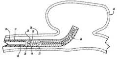
- FIG. 1is an enlarged, partially sectional view of an embodiment of an embolic device deployment system in accordance with the present invention
- FIGS. 2A and 2Bare an enlarged, sectional views, illustrating in more detail the coil deployment system of FIG. 1 ;
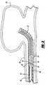
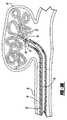
- FIGS. 3 , 3 A, 3 B, and 3 Care enlarged, sectional views of the coil deployment system shown in FIGS. 1 , 2 A and 2 B illustrating the sequential steps in the advancement of the embolic device, removal of a detachment member, and release of the embolic device.
- FIG. 1generally illustrates one embodiment of a vascular occlusive embolic device deployment system 10 which includes a sheath introducer 12 having a lumen 14 extending therethrough and having an elongated pusher member 16 slidably disposed within the lumen 14 of the sheath introducer 12 .
- An elongated engagement member 18is slidably disposed within a lumen of the pusher member 16 and has an aperture 22 extending through the distal end thereof.
- the central axis of the aperture 22extends generally parallel to the axis of the pusher member 16 .
- the engagement member 18is preferably formed of a small diameter resilient wire, such as Nitinol, and includes a flattened distal end having a passageway extending therethrough to form the aperture 22 .
- the deployment system 10also includes an embolic device 23 , which as illustrated, preferably takes the form of a helically wound embolic coil 23 a , which is disposed in the distal section of the sheath introducer 12 . While the embolic device as illustrated is shown as a helically wound coil, various other types of coil configurations could be delivered using this system.
- a weld, or solder, bead 24is formed at the distal end of the embolic device 23 to provide an a traumatic tip for the embolic device.
- the proximal turn 26 of the helically wound coil 23 ais spaced apart from the more distal turns and is closed upon itself to form a retaining ring 28 .
- the retaining ring 28has a central axis which is generally coaxial with the central axis of the delivery catheter 12 and is also coaxial to the central axis of the helically wound embolic coil 23 a .
- One method of forming the retaining ring 28is to simply stretch the proximal turn of the helically wound coil 23 a apart from the more distal turns and then close the proximal turn onto itself.
- the engagement member 18normally extends in a direction parallel to the central axis of the pusher member 16 but is deflected to extend through the retaining ring 28 and is constrained by a detachment member 30 .
- the elongated detachment member 30extends from the proximal end of the deployment system 10 and through a lumen in the pusher member and then through the aperture 22 of the engagement member 18 and serves the function of interlocking the retaining ring 23 a to the pusher member 16 until such time as the detachment member 30 is withdrawn proximally.
- the detachment member 30preferably takes the form of a small diameter elongate filament, however, other forms such as wires or tubular structures are also suitable. While the detachment member 30 is preferably formed of nitinol, other metals and materials such as, stainless steel, PTFE, nylon, ceramic or glass fiber and composites may also be suitable.
- FIGS. 2A and 2Billustrate the interlocking arrangement between the embolic device 23 and the pusher member 16 as shown in FIG. 1 , however, these figures illustrate the operation of the deployment system once the pusher member 16 has been moved to a position so that the distal end of the pusher member 16 extends slightly out of the distal end of the sheath introducer 12 or a delivery catheter thereby exposing the embolic device 23 .
- the detachment member 30may be pulled proximally to withdraw the detachment member from the aperture 22 of the engagement member 18 to thereby cause the engagement member to disengage from the retaining ring 28 of the embolic device thereby releasing the embolic device 23 at a preselected position.
- the detachment sequence described above and illustrated in FIGS. 2A and 2Bmay be executed while the embolic device 23 is still within the lumen of sheath introducer 12 or a delivery catheter.
- the embolic devicemay be placed at a desired location within a vessel, or within an aneurysm, with the configuration of the device deployment system as shown in FIGS. 2A and 2B . If it is determined that the embolic device is improperly positioned the embolic device may then be withdrawn from that location and placed at another location, or even removed from the body by first withdrawing the pusher member 16 and the embolic device totally back into the delivery catheter. Once the embolic device has been entirely withdrawn back into the delivery catheter, the catheter may then be moved to a more desirable location and the embolic device may then be released at the new location.
- FIGS. 3 , 3 A and 3 Bgenerally illustrate the sequence of placing an embolic device, such as a helical wound coil 23 a into an aneurysm 36 which extends from a vessel wall 38 .
- FIG. 3illustrates the vascular occlusive embolic device deployment system 10 in the same configuration as shown in FIG. 1 after the pusher member and associated embolic device have been inserted into a delivery catheter 35 and advanced into a position for deployment of the embolic device 23 , shown as a helical embolic coil, into the aneurysm 36 .
- FIG. 3Aillustrates the deployment device having a configuration similar to FIG.
- the pusher membermay be withdrawn thereby withdrawing the embolic device back into the delivery catheter 35 for repositioning to a different location, or alternatively, to remove the embolic coil entirely from the body.
- FIG. 3Billustrates the deployment device after the detachment member 30 has been removed from the engagement member 18 thereby releasing the embolic device within the aneurysm 36
- FIG. 3Cillustrates the deployment device after the pusher member 16 has been withdrawn back into the delivery catheter 35 at the completion of the procedure or alternatively in order to insert a second coil through the delivery catheter 35 and into the same aneurysm.
Landscapes
- Health & Medical Sciences (AREA)
- Surgery (AREA)
- Life Sciences & Earth Sciences (AREA)
- Heart & Thoracic Surgery (AREA)
- Molecular Biology (AREA)
- Vascular Medicine (AREA)
- Engineering & Computer Science (AREA)
- Biomedical Technology (AREA)
- Reproductive Health (AREA)
- Medical Informatics (AREA)
- Nuclear Medicine, Radiotherapy & Molecular Imaging (AREA)
- Animal Behavior & Ethology (AREA)
- General Health & Medical Sciences (AREA)
- Public Health (AREA)
- Veterinary Medicine (AREA)
- Neurosurgery (AREA)
- Surgical Instruments (AREA)
Abstract
Description
Claims (9)
Priority Applications (1)
| Application Number | Priority Date | Filing Date | Title |
|---|---|---|---|
| US11/541,022US7901444B2 (en) | 2006-09-29 | 2006-09-29 | Embolic coil delivery system with mechanical release mechanism |
Applications Claiming Priority (1)
| Application Number | Priority Date | Filing Date | Title |
|---|---|---|---|
| US11/541,022US7901444B2 (en) | 2006-09-29 | 2006-09-29 | Embolic coil delivery system with mechanical release mechanism |
Publications (2)
| Publication Number | Publication Date |
|---|---|
| US20080082176A1 US20080082176A1 (en) | 2008-04-03 |
| US7901444B2true US7901444B2 (en) | 2011-03-08 |
Family
ID=39262001
Family Applications (1)
| Application Number | Title | Priority Date | Filing Date |
|---|---|---|---|
| US11/541,022Active2028-11-21US7901444B2 (en) | 2006-09-29 | 2006-09-29 | Embolic coil delivery system with mechanical release mechanism |
Country Status (1)
| Country | Link |
|---|---|
| US (1) | US7901444B2 (en) |
Cited By (55)
| Publication number | Priority date | Publication date | Assignee | Title |
|---|---|---|---|---|
| US20090287291A1 (en)* | 2008-04-21 | 2009-11-19 | Becking Frank P | Embolic Device Delivery Systems |
| US8328860B2 (en) | 2007-03-13 | 2012-12-11 | Covidien Lp | Implant including a coil and a stretch-resistant member |
| US8777979B2 (en) | 2006-04-17 | 2014-07-15 | Covidien Lp | System and method for mechanically positioning intravascular implants |
| US8777978B2 (en) | 2006-04-17 | 2014-07-15 | Covidien Lp | System and method for mechanically positioning intravascular implants |
| US8795313B2 (en) | 2011-09-29 | 2014-08-05 | Covidien Lp | Device detachment systems with indicators |
| US8801747B2 (en) | 2007-03-13 | 2014-08-12 | Covidien Lp | Implant, a mandrel, and a method of forming an implant |
| US8945171B2 (en) | 2011-09-29 | 2015-02-03 | Covidien Lp | Delivery system for implantable devices |
| US9011480B2 (en) | 2012-01-20 | 2015-04-21 | Covidien Lp | Aneurysm treatment coils |
| US20150112378A1 (en)* | 2013-10-17 | 2015-04-23 | Cook Medical Technologies Llc | Release mechanism |
| US9050095B2 (en) | 2004-09-22 | 2015-06-09 | Covidien Lp | Medical implant |
| US9149278B2 (en) | 2013-03-13 | 2015-10-06 | DePuy Synthes Products, Inc. | Occlusive device delivery system with mechanical detachment |
| US9198665B2 (en) | 2004-09-22 | 2015-12-01 | Covidien Lp | Micro-spiral implantation device |
| WO2016029228A2 (en) | 2014-08-22 | 2016-02-25 | Parmar Jaywant P | Advanced electromagnetic motion and tracking peripherally inserted central venous catheter system with extended endovascular applications |
| US9282971B2 (en) | 2013-03-14 | 2016-03-15 | Incumedx, Inc. | Implants, methods of manufacturing the same, and devices and methods for delivering the implants to a vascular disorder of a patient |
| US9579104B2 (en) | 2011-11-30 | 2017-02-28 | Covidien Lp | Positioning and detaching implants |
| US9629739B2 (en) | 2013-03-13 | 2017-04-25 | DePuy Synthes Products, LLC | Distal capture device for a self-expanding stent |
| US9687245B2 (en) | 2012-03-23 | 2017-06-27 | Covidien Lp | Occlusive devices and methods of use |
| US9713475B2 (en) | 2014-04-18 | 2017-07-25 | Covidien Lp | Embolic medical devices |
| US9814562B2 (en) | 2009-11-09 | 2017-11-14 | Covidien Lp | Interference-relief type delivery detachment systems |
| US9918718B2 (en) | 2014-08-08 | 2018-03-20 | DePuy Synthes Products, Inc. | Embolic coil delivery system with retractable mechanical release mechanism |
| US9936957B2 (en) | 2011-12-02 | 2018-04-10 | Incumedx, Inc. | Micro-coil assembly |
| US9956100B2 (en) | 2009-09-15 | 2018-05-01 | Brightwater Medical, Inc. | Systems and methods for coupling and decoupling a catheter |
| US9968360B2 (en)* | 2016-05-31 | 2018-05-15 | Spartan Micro, Inc. | Systems and methods for delivering intravascular implants |
| US10052108B2 (en) | 2015-10-30 | 2018-08-21 | Incumedx, Inc. | Devices and methods for delivering an implant to a vascular disorder |
| US10076336B2 (en) | 2013-03-15 | 2018-09-18 | Covidien Lp | Delivery and detachment mechanisms for vascular implants |
| US10159489B2 (en) | 2012-07-30 | 2018-12-25 | Cook Medical Technologies Llc | Systems and methods for delivering multiple embolization coils |
| US10531876B2 (en) | 2016-05-31 | 2020-01-14 | Spartan Micro, Inc. | Systems and methods for delivering intravascular implants |
| US10695161B2 (en) | 2008-09-15 | 2020-06-30 | Merit Medical Systems, Inc. | Convertible nephroureteral catheter |
| US10722391B2 (en) | 2014-08-12 | 2020-07-28 | Merit Medical Systems, Inc. | Systems and methods for coupling and decoupling a catheter |
| EP3490464A4 (en)* | 2016-07-29 | 2020-07-29 | Wallaby Medical, Inc. | Implant delivery systems and methods |
| US11090055B2 (en) | 2015-10-30 | 2021-08-17 | Incumedx Inc. | Devices and methods for delivering an implant to a vascular disorder |
| US11147562B2 (en) | 2018-12-12 | 2021-10-19 | DePuy Synthes Products, Inc. | Systems and methods for embolic implant detachment |
| US11207494B2 (en) | 2019-07-03 | 2021-12-28 | DePuy Synthes Products, Inc. | Medical device delivery member with flexible stretch resistant distal portion |
| US11253265B2 (en) | 2019-06-18 | 2022-02-22 | DePuy Synthes Products, Inc. | Pull wire detachment for intravascular devices |
| US11376013B2 (en) | 2019-11-18 | 2022-07-05 | DePuy Synthes Products, Inc. | Implant delivery system with braid cup formation |
| US11426174B2 (en) | 2019-10-03 | 2022-08-30 | DePuy Synthes Products, Inc. | Medical device delivery member with flexible stretch resistant mechanical release |
| US11432822B2 (en) | 2020-02-14 | 2022-09-06 | DePuy Synthes Products, Inc. | Intravascular implant deployment system |
| US11439403B2 (en) | 2019-09-17 | 2022-09-13 | DePuy Synthes Products, Inc. | Embolic coil proximal connecting element and stretch resistant fiber |
| US11457922B2 (en) | 2020-01-22 | 2022-10-04 | DePuy Synthes Products, Inc. | Medical device delivery member with flexible stretch resistant distal portion |
| WO2023076996A1 (en)* | 2021-10-29 | 2023-05-04 | Spartan Micro, Inc. | Detachment mechanism with a tab for delivering intravascular implants |
| US11701123B2 (en) | 2020-08-21 | 2023-07-18 | Shape Memory Medical, Inc. | Mechanical detachment system for transcatheter devices |
| US11826051B2 (en) | 2017-12-21 | 2023-11-28 | DePuy Synthes Products, Inc. | Implantable medical device detachment system with split tube and cylindrical coupling |
| US11844490B2 (en) | 2021-12-30 | 2023-12-19 | DePuy Synthes Products, Inc. | Suture linkage for inhibiting premature embolic implant deployment |
| US11937824B2 (en) | 2021-12-30 | 2024-03-26 | DePuy Synthes Products, Inc. | Implant detachment systems with a modified pull wire |
| US11937825B2 (en) | 2022-03-02 | 2024-03-26 | DePuy Synthes Products, Inc. | Hook wire for preventing premature embolic implant detachment |
| US11937826B2 (en) | 2022-03-14 | 2024-03-26 | DePuy Synthes Products, Inc. | Proximal link wire for preventing premature implant detachment |
| US11951026B2 (en) | 2020-06-30 | 2024-04-09 | DePuy Synthes Products, Inc. | Implantable medical device detachment system with flexible braid section |
| US11998213B2 (en) | 2021-07-14 | 2024-06-04 | DePuy Synthes Products, Inc. | Implant delivery with modified detachment feature and pull wire engagement |
| US12011171B2 (en) | 2022-01-06 | 2024-06-18 | DePuy Synthes Products, Inc. | Systems and methods for inhibiting premature embolic implant deployment |
| US12053403B2 (en) | 2018-07-12 | 2024-08-06 | Shanghai Wallaby Medical Technologies Co., Inc. | Implant delivery system and method of use |
| US12137915B2 (en) | 2022-03-03 | 2024-11-12 | DePuy Synthes Products, Inc. | Elongating wires for inhibiting premature implant detachment |
| US12226327B2 (en) | 2020-04-15 | 2025-02-18 | Merit Medical Systems, Inc. | Systems and methods for coupling and decoupling a catheter |
| US12376859B2 (en) | 2019-09-17 | 2025-08-05 | DePuy Synthes Products, Inc. | Embolic coil proximal connecting element and stretch resistant fiber |
| US12396730B2 (en) | 2022-09-28 | 2025-08-26 | DePuy Synthes Products, Inc. | Braided implant with detachment mechanism |
| US12402886B2 (en) | 2022-06-23 | 2025-09-02 | DePuy Synthes Products, Inc. | Detachment indicator for implant deployment |
Families Citing this family (30)
| Publication number | Priority date | Publication date | Assignee | Title |
|---|---|---|---|---|
| WO2009140437A1 (en) | 2008-05-13 | 2009-11-19 | Nfocus Neuromedical, Inc. | Braid implant delivery systems |
| WO2010068814A1 (en) | 2008-12-10 | 2010-06-17 | Boston Scientific Scimed, Inc. | Introducer sheath with an embolic coil device and methods for making the same |
| EP2413840B1 (en) | 2009-04-02 | 2016-08-17 | Endoshape, Inc. | Vascular occlusion devices |
| KR20110043799A (en)* | 2009-10-16 | 2011-04-28 | 강호창 | Microcoil assembly |
| AU2010339980C1 (en)* | 2009-12-16 | 2014-07-10 | Endoshape, Inc. | Multi-fiber shape memory device |
| CA2812012C (en) | 2010-09-10 | 2018-01-02 | Medina Medical, Inc. | Devices and methods for the treatment of vascular defects |
| US8998947B2 (en) | 2010-09-10 | 2015-04-07 | Medina Medical, Inc. | Devices and methods for the treatment of vascular defects |
| US10603043B2 (en) | 2012-01-17 | 2020-03-31 | Endoshape, Inc. | Occlusion device for a vascular or biological lumen |
| JP2015512274A (en)* | 2012-03-15 | 2015-04-27 | メディナ メディカル,インコーポレイテッド | Apparatus and method for treating vascular disorder |
| US10327781B2 (en) | 2012-11-13 | 2019-06-25 | Covidien Lp | Occlusive devices |
| CN105073031B (en) | 2013-03-13 | 2017-10-27 | 内形有限公司 | Continuous embolic coil and its carrying method and device |
| US20150327868A1 (en)* | 2014-05-13 | 2015-11-19 | Ndi Tip Teknolojileri Anonim Sirketi | Retractable and rapid disconnect, floating diameter embolic coil product and delivery system |
| CA2972620C (en) | 2015-01-20 | 2023-08-01 | Neurogami Medical, Inc. | Micrograft for the treatment of intracranial aneurysms and method for use |
| US11484319B2 (en) | 2015-01-20 | 2022-11-01 | Neurogami Medical, Inc. | Delivery system for micrograft for treating intracranial aneurysms |
| US10736730B2 (en) | 2015-01-20 | 2020-08-11 | Neurogami Medical, Inc. | Vascular implant |
| US10925611B2 (en) | 2015-01-20 | 2021-02-23 | Neurogami Medical, Inc. | Packaging for surgical implant |
| US10857012B2 (en) | 2015-01-20 | 2020-12-08 | Neurogami Medical, Inc. | Vascular implant |
| US10420563B2 (en)* | 2016-07-08 | 2019-09-24 | Neurogami Medical, Inc. | Delivery system insertable through body lumen |
| CN207721935U (en)* | 2016-07-29 | 2018-08-14 | 上海沃比医疗科技有限公司 | Implantation material transport system |
| US10478195B2 (en) | 2016-08-04 | 2019-11-19 | Covidien Lp | Devices, systems, and methods for the treatment of vascular defects |
| US10576099B2 (en) | 2016-10-21 | 2020-03-03 | Covidien Lp | Injectable scaffold for treatment of intracranial aneurysms and related technology |
| US10675036B2 (en) | 2017-08-22 | 2020-06-09 | Covidien Lp | Devices, systems, and methods for the treatment of vascular defects |
| EP3492024A1 (en)* | 2017-11-29 | 2019-06-05 | Spartan Micro, Inc. | Systems for delivering intravascular implants |
| IT201800010311A1 (en)* | 2018-11-14 | 2020-05-14 | Pfm Medical Ag | SYSTEM FOR THE CONNECTION OF A MEDICAL IMPLANT TO AN INSERTION AID |
| US11730485B2 (en) | 2018-12-17 | 2023-08-22 | Covidien Lp | Devices, systems, and methods for the treatment of vascular defects |
| WO2021092618A1 (en) | 2019-11-04 | 2021-05-14 | Covidien Lp | Devices, systems, and methods for treatment of intracranial aneurysms |
| US11931041B2 (en) | 2020-05-12 | 2024-03-19 | Covidien Lp | Devices, systems, and methods for the treatment of vascular defects |
| CN112773448B (en)* | 2021-02-08 | 2025-09-19 | 北京华脉泰科医疗器械股份有限公司 | Medical instrument implant conveying device |
| US20230277181A1 (en)* | 2022-03-02 | 2023-09-07 | DePuy Synthes Products, Inc. | Flexible feature for embolic implant deployment |
| CN119403497A (en)* | 2022-06-27 | 2025-02-07 | 波士顿科学国际有限公司 | Medical Device Release Systems |
Citations (16)
| Publication number | Priority date | Publication date | Assignee | Title |
|---|---|---|---|---|
| US5108407A (en) | 1990-06-08 | 1992-04-28 | Rush-Presbyterian St. Luke's Medical Center | Method and apparatus for placement of an embolic coil |
| US5122136A (en) | 1990-03-13 | 1992-06-16 | The Regents Of The University Of California | Endovascular electrolytically detachable guidewire tip for the electroformation of thrombus in arteries, veins, aneurysms, vascular malformations and arteriovenous fistulas |
| US5242452A (en) | 1991-10-11 | 1993-09-07 | Kanji Inoue | Device for collapsing an appliance collapsible for insertion into human organs |
| US5263964A (en) | 1992-05-06 | 1993-11-23 | Coil Partners Ltd. | Coaxial traction detachment apparatus and method |
| US5334210A (en) | 1993-04-09 | 1994-08-02 | Cook Incorporated | Vascular occlusion assembly |
| US5350397A (en) | 1992-11-13 | 1994-09-27 | Target Therapeutics, Inc. | Axially detachable embolic coil assembly |
| US5382259A (en) | 1992-10-26 | 1995-01-17 | Target Therapeutics, Inc. | Vasoocclusion coil with attached tubular woven or braided fibrous covering |
| US5911725A (en) | 1997-08-22 | 1999-06-15 | Boury; Harb N. | Intraluminal retrieval catheter |
| US5925059A (en) | 1993-04-19 | 1999-07-20 | Target Therapeutics, Inc. | Detachable embolic coil assembly |
| US6113622A (en) | 1998-03-10 | 2000-09-05 | Cordis Corporation | Embolic coil hydraulic deployment system |
| US6203547B1 (en) | 1997-12-19 | 2001-03-20 | Target Therapeutics, Inc. | Vaso-occlusion apparatus having a manipulable mechanical detachment joint and a method for using the apparatus |
| US20020165569A1 (en) | 1998-12-21 | 2002-11-07 | Kamal Ramzipoor | Intravascular device deployment mechanism incorporating mechanical detachment |
| US20040034363A1 (en)* | 2002-07-23 | 2004-02-19 | Peter Wilson | Stretch resistant therapeutic device |
| US7371251B2 (en)* | 2005-06-02 | 2008-05-13 | Cordis Neurovascular, Inc. | Stretch resistant embolic coil delivery system with mechanical release mechanism |
| US7377932B2 (en)* | 2005-06-02 | 2008-05-27 | Cordis Neurovascular, Inc. | Embolic coil delivery system with mechanical release mechanism |
| US7479155B2 (en)* | 2000-07-28 | 2009-01-20 | Ev3 Endovascular, Inc. | Defect occluder release assembly and method |
- 2006
- 2006-09-29USUS11/541,022patent/US7901444B2/enactiveActive
Patent Citations (16)
| Publication number | Priority date | Publication date | Assignee | Title |
|---|---|---|---|---|
| US5122136A (en) | 1990-03-13 | 1992-06-16 | The Regents Of The University Of California | Endovascular electrolytically detachable guidewire tip for the electroformation of thrombus in arteries, veins, aneurysms, vascular malformations and arteriovenous fistulas |
| US5108407A (en) | 1990-06-08 | 1992-04-28 | Rush-Presbyterian St. Luke's Medical Center | Method and apparatus for placement of an embolic coil |
| US5242452A (en) | 1991-10-11 | 1993-09-07 | Kanji Inoue | Device for collapsing an appliance collapsible for insertion into human organs |
| US5263964A (en) | 1992-05-06 | 1993-11-23 | Coil Partners Ltd. | Coaxial traction detachment apparatus and method |
| US5382259A (en) | 1992-10-26 | 1995-01-17 | Target Therapeutics, Inc. | Vasoocclusion coil with attached tubular woven or braided fibrous covering |
| US5350397A (en) | 1992-11-13 | 1994-09-27 | Target Therapeutics, Inc. | Axially detachable embolic coil assembly |
| US5334210A (en) | 1993-04-09 | 1994-08-02 | Cook Incorporated | Vascular occlusion assembly |
| US5925059A (en) | 1993-04-19 | 1999-07-20 | Target Therapeutics, Inc. | Detachable embolic coil assembly |
| US5911725A (en) | 1997-08-22 | 1999-06-15 | Boury; Harb N. | Intraluminal retrieval catheter |
| US6203547B1 (en) | 1997-12-19 | 2001-03-20 | Target Therapeutics, Inc. | Vaso-occlusion apparatus having a manipulable mechanical detachment joint and a method for using the apparatus |
| US6113622A (en) | 1998-03-10 | 2000-09-05 | Cordis Corporation | Embolic coil hydraulic deployment system |
| US20020165569A1 (en) | 1998-12-21 | 2002-11-07 | Kamal Ramzipoor | Intravascular device deployment mechanism incorporating mechanical detachment |
| US7479155B2 (en)* | 2000-07-28 | 2009-01-20 | Ev3 Endovascular, Inc. | Defect occluder release assembly and method |
| US20040034363A1 (en)* | 2002-07-23 | 2004-02-19 | Peter Wilson | Stretch resistant therapeutic device |
| US7371251B2 (en)* | 2005-06-02 | 2008-05-13 | Cordis Neurovascular, Inc. | Stretch resistant embolic coil delivery system with mechanical release mechanism |
| US7377932B2 (en)* | 2005-06-02 | 2008-05-27 | Cordis Neurovascular, Inc. | Embolic coil delivery system with mechanical release mechanism |
Cited By (77)
| Publication number | Priority date | Publication date | Assignee | Title |
|---|---|---|---|---|
| US9050095B2 (en) | 2004-09-22 | 2015-06-09 | Covidien Lp | Medical implant |
| US9198665B2 (en) | 2004-09-22 | 2015-12-01 | Covidien Lp | Micro-spiral implantation device |
| US8777979B2 (en) | 2006-04-17 | 2014-07-15 | Covidien Lp | System and method for mechanically positioning intravascular implants |
| US8777978B2 (en) | 2006-04-17 | 2014-07-15 | Covidien Lp | System and method for mechanically positioning intravascular implants |
| US8795320B2 (en) | 2006-04-17 | 2014-08-05 | Covidien Lp | System and method for mechanically positioning intravascular implants |
| US8795321B2 (en) | 2006-04-17 | 2014-08-05 | Covidien Lp | System and method for mechanically positioning intravascular implants |
| US8864790B2 (en) | 2006-04-17 | 2014-10-21 | Covidien Lp | System and method for mechanically positioning intravascular implants |
| US8328860B2 (en) | 2007-03-13 | 2012-12-11 | Covidien Lp | Implant including a coil and a stretch-resistant member |
| US8801747B2 (en) | 2007-03-13 | 2014-08-12 | Covidien Lp | Implant, a mandrel, and a method of forming an implant |
| US9289215B2 (en) | 2007-03-13 | 2016-03-22 | Covidien Lp | Implant including a coil and a stretch-resistant member |
| US20090287291A1 (en)* | 2008-04-21 | 2009-11-19 | Becking Frank P | Embolic Device Delivery Systems |
| US11439493B2 (en) | 2008-09-15 | 2022-09-13 | Merit Medical Systems, Inc. | Convertible nephroureteral catheter |
| US10695161B2 (en) | 2008-09-15 | 2020-06-30 | Merit Medical Systems, Inc. | Convertible nephroureteral catheter |
| US9956100B2 (en) | 2009-09-15 | 2018-05-01 | Brightwater Medical, Inc. | Systems and methods for coupling and decoupling a catheter |
| US9814562B2 (en) | 2009-11-09 | 2017-11-14 | Covidien Lp | Interference-relief type delivery detachment systems |
| US8795313B2 (en) | 2011-09-29 | 2014-08-05 | Covidien Lp | Device detachment systems with indicators |
| US8945171B2 (en) | 2011-09-29 | 2015-02-03 | Covidien Lp | Delivery system for implantable devices |
| US10335155B2 (en) | 2011-11-30 | 2019-07-02 | Covidien Lp | Positioning and detaching implants |
| US9579104B2 (en) | 2011-11-30 | 2017-02-28 | Covidien Lp | Positioning and detaching implants |
| US9936957B2 (en) | 2011-12-02 | 2018-04-10 | Incumedx, Inc. | Micro-coil assembly |
| US10893868B2 (en) | 2012-01-20 | 2021-01-19 | Covidien Lp | Aneurysm treatment coils |
| US9011480B2 (en) | 2012-01-20 | 2015-04-21 | Covidien Lp | Aneurysm treatment coils |
| US9687245B2 (en) | 2012-03-23 | 2017-06-27 | Covidien Lp | Occlusive devices and methods of use |
| US10159489B2 (en) | 2012-07-30 | 2018-12-25 | Cook Medical Technologies Llc | Systems and methods for delivering multiple embolization coils |
| US9149278B2 (en) | 2013-03-13 | 2015-10-06 | DePuy Synthes Products, Inc. | Occlusive device delivery system with mechanical detachment |
| US9629739B2 (en) | 2013-03-13 | 2017-04-25 | DePuy Synthes Products, LLC | Distal capture device for a self-expanding stent |
| US10149676B2 (en) | 2013-03-14 | 2018-12-11 | Incumedx, Inc. | Implants, methods of manufacturing the same, and devices and methods for delivering the implants to a vascular disorder of a patient |
| US9282971B2 (en) | 2013-03-14 | 2016-03-15 | Incumedx, Inc. | Implants, methods of manufacturing the same, and devices and methods for delivering the implants to a vascular disorder of a patient |
| US11490896B2 (en) | 2013-03-15 | 2022-11-08 | Covidien Lp | Delivery and detachment mechanisms for vascular implants |
| US10076336B2 (en) | 2013-03-15 | 2018-09-18 | Covidien Lp | Delivery and detachment mechanisms for vascular implants |
| US10743882B2 (en) | 2013-03-15 | 2020-08-18 | Covidien Lp | Delivery and detachment mechanisms for vascular implants |
| US20150112378A1 (en)* | 2013-10-17 | 2015-04-23 | Cook Medical Technologies Llc | Release mechanism |
| US9687246B2 (en)* | 2013-10-17 | 2017-06-27 | Cook Medical Technologies Llc | Release mechanism |
| US9713475B2 (en) | 2014-04-18 | 2017-07-25 | Covidien Lp | Embolic medical devices |
| US10799243B2 (en) | 2014-08-08 | 2020-10-13 | DePuy Synthes Products, Inc. | Embolic coil delivery system with retractable mechanical release mechanism |
| US11871931B2 (en) | 2014-08-08 | 2024-01-16 | DePuy Synthes Products, Inc. | Embolic coil delivery system with retractable mechanical release mechanism |
| US9918718B2 (en) | 2014-08-08 | 2018-03-20 | DePuy Synthes Products, Inc. | Embolic coil delivery system with retractable mechanical release mechanism |
| US10722391B2 (en) | 2014-08-12 | 2020-07-28 | Merit Medical Systems, Inc. | Systems and methods for coupling and decoupling a catheter |
| US11931275B2 (en) | 2014-08-12 | 2024-03-19 | Merit Medical Systems, Inc. | Systems and methods for coupling and decoupling a catheter |
| US10737061B2 (en) | 2014-08-22 | 2020-08-11 | Jaywant P. Parmar | Advanced electromagnetic motion and tracking peripherally inserted central venous catheter system with extended endovascular applications |
| WO2016029228A2 (en) | 2014-08-22 | 2016-02-25 | Parmar Jaywant P | Advanced electromagnetic motion and tracking peripherally inserted central venous catheter system with extended endovascular applications |
| US10052108B2 (en) | 2015-10-30 | 2018-08-21 | Incumedx, Inc. | Devices and methods for delivering an implant to a vascular disorder |
| US11849956B2 (en) | 2015-10-30 | 2023-12-26 | Arissa Medical, Inc. | Devices and methods for delivering an implant to a vascular disorder |
| US10966727B2 (en) | 2015-10-30 | 2021-04-06 | Incumedx, Inc. | Devices and methods for delivering an implant to a vascular disorder |
| US11090055B2 (en) | 2015-10-30 | 2021-08-17 | Incumedx Inc. | Devices and methods for delivering an implant to a vascular disorder |
| US9968360B2 (en)* | 2016-05-31 | 2018-05-15 | Spartan Micro, Inc. | Systems and methods for delivering intravascular implants |
| US10856878B2 (en) | 2016-05-31 | 2020-12-08 | Spartan Micro, Inc. | Systems and methods for delivering intravascular implants |
| US10531876B2 (en) | 2016-05-31 | 2020-01-14 | Spartan Micro, Inc. | Systems and methods for delivering intravascular implants |
| EP3490464A4 (en)* | 2016-07-29 | 2020-07-29 | Wallaby Medical, Inc. | Implant delivery systems and methods |
| US10932933B2 (en) | 2016-07-29 | 2021-03-02 | Shanghai Wallaby Medical Technologies Co., Inc. | Implant delivery systems and methods |
| US11826051B2 (en) | 2017-12-21 | 2023-11-28 | DePuy Synthes Products, Inc. | Implantable medical device detachment system with split tube and cylindrical coupling |
| US12053403B2 (en) | 2018-07-12 | 2024-08-06 | Shanghai Wallaby Medical Technologies Co., Inc. | Implant delivery system and method of use |
| US11147562B2 (en) | 2018-12-12 | 2021-10-19 | DePuy Synthes Products, Inc. | Systems and methods for embolic implant detachment |
| US12419645B2 (en) | 2019-06-18 | 2025-09-23 | DePuy Synthes Products, Inc. | Pull wire detachment for intravascular devices |
| US11253265B2 (en) | 2019-06-18 | 2022-02-22 | DePuy Synthes Products, Inc. | Pull wire detachment for intravascular devices |
| US11207494B2 (en) | 2019-07-03 | 2021-12-28 | DePuy Synthes Products, Inc. | Medical device delivery member with flexible stretch resistant distal portion |
| US11439403B2 (en) | 2019-09-17 | 2022-09-13 | DePuy Synthes Products, Inc. | Embolic coil proximal connecting element and stretch resistant fiber |
| US12127744B2 (en) | 2019-09-17 | 2024-10-29 | DePuy Synthes Products, Inc. | Embolic coil proximal connecting element and stretch resistant fiber |
| US12376859B2 (en) | 2019-09-17 | 2025-08-05 | DePuy Synthes Products, Inc. | Embolic coil proximal connecting element and stretch resistant fiber |
| US11426174B2 (en) | 2019-10-03 | 2022-08-30 | DePuy Synthes Products, Inc. | Medical device delivery member with flexible stretch resistant mechanical release |
| US12419646B2 (en) | 2019-10-03 | 2025-09-23 | DePuy Synthes Products, Inc. | Medical device delivery member with flexible stretch resistant mechanical release |
| US11376013B2 (en) | 2019-11-18 | 2022-07-05 | DePuy Synthes Products, Inc. | Implant delivery system with braid cup formation |
| US11457922B2 (en) | 2020-01-22 | 2022-10-04 | DePuy Synthes Products, Inc. | Medical device delivery member with flexible stretch resistant distal portion |
| US11432822B2 (en) | 2020-02-14 | 2022-09-06 | DePuy Synthes Products, Inc. | Intravascular implant deployment system |
| US12226327B2 (en) | 2020-04-15 | 2025-02-18 | Merit Medical Systems, Inc. | Systems and methods for coupling and decoupling a catheter |
| US11951026B2 (en) | 2020-06-30 | 2024-04-09 | DePuy Synthes Products, Inc. | Implantable medical device detachment system with flexible braid section |
| US11701123B2 (en) | 2020-08-21 | 2023-07-18 | Shape Memory Medical, Inc. | Mechanical detachment system for transcatheter devices |
| US11998213B2 (en) | 2021-07-14 | 2024-06-04 | DePuy Synthes Products, Inc. | Implant delivery with modified detachment feature and pull wire engagement |
| WO2023076996A1 (en)* | 2021-10-29 | 2023-05-04 | Spartan Micro, Inc. | Detachment mechanism with a tab for delivering intravascular implants |
| US11937824B2 (en) | 2021-12-30 | 2024-03-26 | DePuy Synthes Products, Inc. | Implant detachment systems with a modified pull wire |
| US11844490B2 (en) | 2021-12-30 | 2023-12-19 | DePuy Synthes Products, Inc. | Suture linkage for inhibiting premature embolic implant deployment |
| US12011171B2 (en) | 2022-01-06 | 2024-06-18 | DePuy Synthes Products, Inc. | Systems and methods for inhibiting premature embolic implant deployment |
| US11937825B2 (en) | 2022-03-02 | 2024-03-26 | DePuy Synthes Products, Inc. | Hook wire for preventing premature embolic implant detachment |
| US12137915B2 (en) | 2022-03-03 | 2024-11-12 | DePuy Synthes Products, Inc. | Elongating wires for inhibiting premature implant detachment |
| US11937826B2 (en) | 2022-03-14 | 2024-03-26 | DePuy Synthes Products, Inc. | Proximal link wire for preventing premature implant detachment |
| US12402886B2 (en) | 2022-06-23 | 2025-09-02 | DePuy Synthes Products, Inc. | Detachment indicator for implant deployment |
| US12396730B2 (en) | 2022-09-28 | 2025-08-26 | DePuy Synthes Products, Inc. | Braided implant with detachment mechanism |
Also Published As
| Publication number | Publication date |
|---|---|
| US20080082176A1 (en) | 2008-04-03 |
Similar Documents
| Publication | Publication Date | Title |
|---|---|---|
| US7901444B2 (en) | Embolic coil delivery system with mechanical release mechanism | |
| US7377932B2 (en) | Embolic coil delivery system with mechanical release mechanism | |
| CA2551376C (en) | Stretch resistant embolic coil delivery system with mechanical release mechanism | |
| US7371251B2 (en) | Stretch resistant embolic coil delivery system with mechanical release mechanism | |
| US7799052B2 (en) | Stretch resistant embolic coil delivery system with mechanical release mechanism | |
| US7811305B2 (en) | Stretch resistant embolic coil delivery system with spring release mechanism | |
| US7371252B2 (en) | Stretch resistant embolic coil delivery system with mechanical release mechanism | |
| US7819891B2 (en) | Stretch resistant embolic coil delivery system with spring release mechanism | |
| CA2571004C (en) | Stretch resistant embolic coil delivery system with mechanical release mechanism | |
| US7985238B2 (en) | Embolic coil delivery system with spring wire release mechanism | |
| US7367987B2 (en) | Stretch resistant embolic coil delivery system with mechanical release mechanism | |
| US7819892B2 (en) | Embolic coil delivery system with spring wire release mechanism | |
| EP1738697B1 (en) | Stretch resistant embolic coil delivery system with mechanical release mechanism | |
| US7918872B2 (en) | Embolic device delivery system with retractable partially coiled-fiber release | |
| EP1621148B1 (en) | Embolic device deployment system with filament release | |
| US20060276833A1 (en) | Stretch resistant embolic coil delivery system with spring assisted release mechanism | |
| EP1738698A2 (en) | Embolic coil delivery system |
Legal Events
| Date | Code | Title | Description |
|---|---|---|---|
| AS | Assignment | Owner name:CORDIS DEVELOPMENT CORPORATION, FLORIDA Free format text:ASSIGNMENT OF ASSIGNORS INTEREST;ASSIGNOR:SLAZAS, ROBERT R.;REEL/FRAME:019091/0235 Effective date:20070320 | |
| AS | Assignment | Owner name:CORDIS NEUROVASCULAR, INC., FLORIDA Free format text:MERGER;ASSIGNORS:CORDIS DEVELOPMENT CORPORATION;CORDIS NEUROVASCULAR, INC.;REEL/FRAME:023085/0329 Effective date:20081229 Owner name:CODMAN & SHURTLEFF, INC., MASSACHUSETTS Free format text:MERGER;ASSIGNORS:CORDIS DEVELOPMENT CORPORATION;CORDIS NEUROVASCULAR, INC.;REEL/FRAME:023085/0329 Effective date:20081229 Owner name:CORDIS NEUROVASCULAR, INC.,FLORIDA Free format text:MERGER;ASSIGNORS:CORDIS DEVELOPMENT CORPORATION;CORDIS NEUROVASCULAR, INC.;REEL/FRAME:023085/0329 Effective date:20081229 Owner name:CODMAN & SHURTLEFF, INC.,MASSACHUSETTS Free format text:MERGER;ASSIGNORS:CORDIS DEVELOPMENT CORPORATION;CORDIS NEUROVASCULAR, INC.;REEL/FRAME:023085/0329 Effective date:20081229 | |
| AS | Assignment | Owner name:CODMAN & SHURTLEFF, INC., MASSACHUSETTS Free format text:CORRECTIVE ASSIGNMENT TO CORRECT THE RE-RECORDING ASSIGNMENTS TO REMOVE INCORRECT DATA RECORDED ON 08/12/2009. PREVIOUSLY RECORDED ON REEL 023085 FRAME 0329. ASSIGNOR(S) HEREBY CONFIRMS THE MERGER OF CORDIS DEVELOPMENT CORP. AND CORDIS NEUROVASCULAR, INC. INTO CODMAN & SHURTLEFF;ASSIGNORS:CORDIS DEVELOPMENT CORPORATION;CORDIS NEUROVASCULAR, INC.;REEL/FRAME:024776/0472 Effective date:20081229 | |
| STCF | Information on status: patent grant | Free format text:PATENTED CASE | |
| FPAY | Fee payment | Year of fee payment:4 | |
| MAFP | Maintenance fee payment | Free format text:PAYMENT OF MAINTENANCE FEE, 8TH YEAR, LARGE ENTITY (ORIGINAL EVENT CODE: M1552); ENTITY STATUS OF PATENT OWNER: LARGE ENTITY Year of fee payment:8 | |
| MAFP | Maintenance fee payment | Free format text:PAYMENT OF MAINTENANCE FEE, 12TH YEAR, LARGE ENTITY (ORIGINAL EVENT CODE: M1553); ENTITY STATUS OF PATENT OWNER: LARGE ENTITY Year of fee payment:12 |