US7901433B2 - Occipito-cervical stabilization system and method - Google Patents
Occipito-cervical stabilization system and methodDownload PDFInfo
- Publication number
- US7901433B2 US7901433B2US11/542,786US54278606AUS7901433B2US 7901433 B2US7901433 B2US 7901433B2US 54278606 AUS54278606 AUS 54278606AUS 7901433 B2US7901433 B2US 7901433B2
- Authority
- US
- United States
- Prior art keywords
- rod
- plate
- mode
- relative
- transverse
- Prior art date
- Legal status (The legal status is an assumption and is not a legal conclusion. Google has not performed a legal analysis and makes no representation as to the accuracy of the status listed.)
- Expired - Fee Related, expires
Links
Images


Classifications
- A—HUMAN NECESSITIES
- A61—MEDICAL OR VETERINARY SCIENCE; HYGIENE
- A61B—DIAGNOSIS; SURGERY; IDENTIFICATION
- A61B17/00—Surgical instruments, devices or methods
- A61B17/56—Surgical instruments or methods for treatment of bones or joints; Devices specially adapted therefor
- A61B17/58—Surgical instruments or methods for treatment of bones or joints; Devices specially adapted therefor for osteosynthesis, e.g. bone plates, screws or setting implements
- A61B17/68—Internal fixation devices, including fasteners and spinal fixators, even if a part thereof projects from the skin
- A61B17/70—Spinal positioners or stabilisers, e.g. stabilisers comprising fluid filler in an implant
- A61B17/7055—Spinal positioners or stabilisers, e.g. stabilisers comprising fluid filler in an implant connected to sacrum, pelvis or skull
Definitions
- the present inventiongenerally relates to spinal fixation systems and the like, and in more particular applications, to systems that fixate a portion of the skull to the spine, typically the cervical spine, for correction, fixation, and/or stabilization of a human spine.
- Spinal fixationsuch as lumbar sacral fusion and the correction of spinal deformities such as scoliotic curves, is a well known and frequently used medical procedure.
- Pedicle, lateral, and oblique mounting devicesmay be used to secure corrective spinal instrumentation to a portion of the spine that has been selected to be fused by arthrodesis.
- a spinal fixation systemtypically includes corrective spinal instrumentation that is attached to selected vertebra of the spine by screws, hooks, and clamps.
- the corrective spinal instrumentationincludes spinal rods or plates that are generally parallel to the patient's back.
- the corrective spinal instrumentationmay also include transverse connecting rods that extend between neighboring spinal rods.
- Spinal fixation systemsare used to correct problems in the lumbar and thoracic portions of the spine, and are often installed posterior to the spine on opposite sides of the spinous process and adjacent to the transverse process.
- Fixation of the skull to the cervical spinemay be used to treat trauma to the neck, degenerative diseases such as rheumatoid arthritis, and pain that is otherwise unresponsive to treatment.
- Current implantable devices designed to immobilize the skull with respect to the upper cervical spinehave to be individually tailored. Often, such devices are assemblies of several components not designed specifically for fusing the cervical spine to the skull. However, devices specifically designed for fusing the cervical spine to the skull are currently being introduced.
- U.S. Pat. No. 6,146,382issued to John Hurlbert on Nov. 14, 2000, shows one such device and is incorporated herein by reference as if full set forth herein.
- a systemfor mechanically fixating a region of a skull to a portion of a spine.
- the systemincludes a plate configured to contact the region of the skull and be secured thereto, a spinal rod configured to extend from a location adjacent to the plate for connection thereto to a location adjacent at least one vertebra for connection thereto, the rod forming an angle ⁇ with respect to the plate about a transverse axis, and a variable connection configured to secure the rod to the plate.
- variable connectionhas a first mode connecting the rod and the plate wherein the angle ⁇ can be freely varied without requiring deformation of the rod and the plate and a second mode connecting the rod and the plate wherein the rod and the plate are locked at a particular value of the angle ⁇ selected to maintain a desired curvature of the spine.
- connectionis configured to also allow the rod to be adjusted laterally with respect to the plate in the first mode without requiring deformation of the rod and the plate, and to be locked at a lateral position relative to the plate in the second mode.
- connectionis configured to also allow the rod to be adjusted longitudinally with respect to the plate in the first mode without requiring deformation of the rod and the plate, and to be locked at a longitudinal position relative to the plate in the second mode.
- connectionis configured to allow a second angle formed between the rod and the plate to be adjusted in the first mode without requiring deformation of the rod and the plate, and for the rod and the plate to be locked at a particular value of the second angle in the second mode.
- variable connectionincludes a lateral arm integral with the plate and extending laterally along the transverse axis relative to the spine, and a connector including a body having a transverse opening configured to receive the arm and a longitudinal opening configured to receive a proximate portion of the rod adjacent the plate.
- the transverse openingis configured to pivot freely about the transverse axis in the first mode and to lock to the arm in the second mode.
- the lateral arm and the transverse openingare configured to also allow the connector to be adjusted laterally with respect to the plate in the first mode without requiring deformation of the rod and the plate, and to be locked at a lateral position relative to the plate in the second mode.
- the longitudinal openingis configured to also allow the rod to be adjusted longitudinally with respect to the plate in the first mode without requiring deformation of the rod and the plate, and to be locked at a longitudinal position relative to the plate in the second mode.
- the lateral arm and the transverse openingare configured to allow a second angle formed between the rod and the plate to be adjusted in the first mode without requiring deformation of the rod and the plate, and for the rod and the plate to be locked at a particular value of the second angle in the second mode.
- the bodyhas a lock opening connecting the transverse and longitudinal openings and extending normal to the transverse and longitudinal openings.
- the connectorfurther includes a clamp plug configured to be received in the lock opening at a location between the transverse and longitudinal openings, and a lock configured to engage the lock opening and clamp the clamp plug, the lateral arm, and the rod in the second mode.
- the lateral armhas a first set of spline teeth and the plug has a second set of spline teeth, the first and second sets of spline teeth being disengaged in the first mode and engaged in the second mode.
- the lockhas external threads and the locking opening has internal threads that mate with the lock in both the first and second modes.
- the bodyhas first and second lock openings, with the first lock opening extending into the transverse opening, and second lock opening extending into the longitudinal opening.
- the connectorfurther includes first and second locks. The first lock is configured to engage the first lock opening and clamp the lateral arm to the body, and the second lock is configured to engage the second lock opening and clamp the rod to the body.
- each of the lockshave external threads and each of the locking openings has internal threads that mate with the corresponding lock in both the first and second modes.
- the systemfurther includes a second spinal rod and a second variable connection.
- the second spinal rodis configured to extend from a location adjacent to the plate for connection thereto to a location adjacent at least one vertebra for connection thereto.
- the first and second rodsare positioned on laterally opposite sides of the plate from each other.
- the second variable connectionis configured to secure the second rod to the plate, with the second connection having a first mode connecting the second rod and the plate wherein an angle formed between the second rod and the plate can be freely varied without requiring deformation of the second rod and the plate, and a second mode connecting the second rod and the plate wherein the second rod and the plate are locked at a particular value of the angle selected to maintain a desired curvature of the spine.
- a systemfor mechanically fixating a region of a skull to a portion of a spine.
- the systemincludes a plate configured to contact the region of the skull and be secured thereto, a spinal rod configured to extend from a location adjacent to the plate for connection thereto to a location adjacent at least one vertebra for connection thereto, and a variable connection configured to secure the rod to the plate.
- the connectionhas first and second modes connecting the rod and the plate. In the first mode, a relative position of the rod and the plate is adjustable with respect to at least four degrees of freedom of motion without requiring deformation of the rod and the plate. In the second mode, the rod and the plate are locked in a particular relative position with respect to the at least four degrees of freedom of motion to maintain a desired curvature of the spine.
- variable connectionis configured to allow adjustment of the relative position for the rod and the plate with respect to a fifth degree of freedom of motion in the first mode without requiring deformation of the rod and the plate.
- one of the degrees of freedom of motionis a rotation about a laterally extending axis.
- another one of the degrees of freedom of motionis a rotation about an axis that is perpendicular to both a laterally extending axis and a longitudinally extending axis.
- another one of the degrees of freedom of motionis a translation along the laterally extending axis.
- another one of the degrees of freedom of motionis a translation along a longitudinally extending axis.
- another one of the degrees of freedom of motionis a rotation about a longitudinally extending axis.
- variable connectionincludes a lateral arm integral with the plate and extending laterally relative to the spine, and a connector including a body having a transverse opening configured to receive the arm and a longitudinal opening configured to receive a proximate portion of the rod adjacent the plate.
- the transverse openingis configured to pivot about the arm and slide along the arm in the first mode and to lock to the arm in the second mode.
- the longitudinal openingis configured to allow the rod to rotate about a longitudinal axis defined by the rod and to slide along the longitudinal axis in the first mode and to lock to the rod in the second mode.
- the transverse openingis configured to pivot relative to the arm about an axis perpendicular to both the longitudinal axis and a laterally extending axis defined by the arm in the first mode.
- the systemfurther includes a second spinal rod and a second variable connection.
- the second rodis configured to extend from a location adjacent to the plate for connection thereto to a location adjacent at least one vertebra for connection thereto, with the first and second rods positioned on laterally opposite sides of the plate from each other.
- the second variable connectionis configured to secure the second rod to the plate, the second connection having first and second modes connecting the second rod and the plate.
- a relative position of the second rod and the plateis adjustable with respect to at least four degrees of freedom of motion without requiring deformation of the second rod and the plate.
- the second rod and the plateare locked in a particular relative position with respect to the at least four degrees of freedom of motion to maintain a desired curvature of the spine.
- the methodincludes the steps of:
- the methodfurther includes the step of adjusting a lateral position of the rod relative to the plate without requiring deformation of the rod or the plate.
- the methodfurther includes the step of adjusting a longitudinal position of the rod relative to the plate without requiring deformation of the rod or the plate.
- the methodfurther includes the step of adjusting an angular position of the rod relative to the plate about an axis that is perpendicular to both a laterally extending axis and a longitudinally extending axis without requiring deformation of the rod or the plate.
- the methodfurther includes the step of adjusting an angular position of the rod relative to the plate about a longitudinal axis defined by the rod without requiring deformation of the rod or the plate.
- the methodfurther includes at least three of the following steps:
- the methodincludes the steps of:
- one of the degrees of freedom of motionis a rotation about a laterally extending axis.
- another one of the degrees of freedom of motionis a rotation about an axis that is perpendicular to both a laterally extending axis and a longitudinally extending axis.
- another one of the degrees of freedom of motionis a translation along the laterally extending axis.
- another one of the degrees of freedom of motionis a translation along a longitudinally extending axis.
- another one of the degrees of freedom of motionis a rotation about a longitudinally extending axis.
- the adjusting stepis performed after the connecting step and before the locking step.
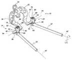
- FIGS. 1 and 2depict an occipito-cervical spinal fixation system embodying the present invention in use, with FIG. 1 being a view looking upward along a portion of a spinal column toward an occiput of a skull, and FIG. 2 being a lateral view;
- FIG. 3is a perspective view showing selected components of the fixation system of FIGS. 1 and 2 ;
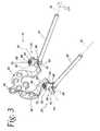
- FIG. 4is a plan or posterior view of the fixation system of FIG. 3 ;
- FIG. 5is a bottom view taken from line 5 - 5 in FIG. 4 ;
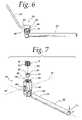
- FIG. 6is a side or lateral view taken from 6 - 6 in FIG. 4 ;
- FIG. 7an exploded, perspective view showing selected components of the fixation system of FIGS. 1-6 ;
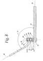
- FIG. 8is a section view taken from line 8 - 8 in FIG. 4 ;
- FIG. 9is a perspective view showing alternate embodiments for selected components of the fixation system.
- FIG. 10is a perspective view showing another alternate embodiment for selected components of the fixation system.
- FIG. 11is a side or lateral section view taken from line 11 - 11 in FIG. 10 .
- an occipito-cervical spinal fixation system 10is shown for mechanically fixating a region of a skull 12 to a portion of a spinal column 14 .
- the system 10includes a plate 20 , at least one spinal rod 22 , (but more typically two of the spinal rods 22 ) and a variable connection, shown generally by arrow 24 , for each spinal rod 22 .
- the plate 20is configured to contact the occiput or occipital bone 16 of the skull and be secured thereto.
- the spinal rod 22is configured to extend from a location adjacent the plate 20 for connection thereto to a location adjacent at least one of the vertebra 30 of the spine 14 for connection thereto.
- the variable connection 24is configured to connect the rod 22 to the plate 20 in first and second modes, with the first mode connecting the plate 20 and rod 22 while allowing the relative position of the rod 22 to the plate 20 to be adjusted without requiring deformation of the rod 22 and the plate 20 , and the second mode locking the plate 20 and the rod 22 at a particular relative position to maintain a desired positioning of the skull 20 and spine 14 .
- the components of the fixation systemare preferably configured to substantially immobilize the skull 12 with respect to the spinal column 14 during use with the connection 24 in the second mode.
- the components of the fixation system 10are preferably made from a suitable biocompatible material, such as titanium or stainless steel.
- the plate 20preferably includes a plurality of openings 36 formed therein for receiving connecting members 38 .
- connecting members 38may be inserted into holes formed in the skull 12 to secure the plate 20 to the occiput 16 such that movement of the skull 12 with respect to a portion of the spine is inhibited.
- connecting members 38preferably are a suitable bone screw, many of which are known.
- the plate 20While any shape may be used for the plate 20 , it is preferred that the plate 20 have a shape that generally conforms to the occiput 16 , with the illustrated horseshoe shape being highly preferred because it offers multiple options for placement of the openings 36 and the associated connecting members 38 and is compatible with the use of two laterally positioned rods 22 , which is typical of most spinal fixation systems. It is also preferred that the plate 20 include a central portion 40 that extends longitudinally to provide multiple possible locations for the openings 36 and the associated connecting members 38 central to the occiput 16 .
- the rod 22supports and preferably immobilizes one or more levels of the spine 14 and can be of any suitable construction, many of which are known.
- the rod 22will be in the form of a straight, cylindrically shaped metallic rod extending along a longitudinal axis 42 and formed of a suitable biocompatible material that can be deformed along its length as required to conform to the patient morphology.
- pre-bent or pre-deformed rods and/or noncylindrical rodscan also be used in the system 10 .
- the rod 22has a proximate end portion 44 that is adjacent the plate 20 for connection thereto, and a length extending to a distal end portion 46 adjacent at least one of the vertebra 30 .
- At least the distal end 46 of the rod 22will be affixed to at least one of the vertebra 30 using a suitable anchoring system, many of which are known and which will typically include a bone screw or bolt and some sort of rod connector that is either integral with the bone screw or otherwise connectable to the bone screw.
- a suitable anchoring systemmany of which are known and which will typically include a bone screw or bolt and some sort of rod connector that is either integral with the bone screw or otherwise connectable to the bone screw.
- the variable connection 24includes a lateral arm 50 and a connector 52 .
- the lateral arm 50is formed integral with the plate 20 and extends laterally along a transverse axis 54 relative to the spine.
- the arm 50 and axis 54are normal to the mid-sagittal plane, shown schematically by dashed line 56 in FIG. 1 and to the longitudinal axis, shown schematically at 58 in FIG. 1 , of the spine 14 lying in the mid-sagittal plane.
- the connector 52connects the arm 50 and the rod 22 and allows for adjustment of the relative position between the arm 50 and the rod 22 while the rod 22 and the arm 50 are connected in the first mode.
- the connector 52includes a body 62 having a transverse opening 64 configured to receive the arm 50 , a longitudinal opening 66 configured to receive the proximate end portion 44 of the rod 22 , and a lock opening 68 , preferably extending along an axis 69 that is aligned with and perpendicular to both the transverse and longitudinal openings 64 , 66 to connect the transverse and longitudinal openings 64 , 66 .
- the transverse opening 64is oversized at each end with respect to the outer surface of the lateral arm 50 in order to allow pivoting of the body 62 on the arm 50 about the axis 69 in the first mode.
- the connector 52further includes a clamp plug 70 and a lock 72 that are received in the lock opening 68 and preferably are configured to operate in the opening 68 to allow free rotational and translational movement of the arm 50 and the rod 22 in the respective openings 64 and 66 in the first mode, and to clamp the arm 50 and the rod 22 against rotational and translational movement in the respective openings 64 and 66 in the second mode.
- the clamp plug 70is configured to be received in the lock opening 68 at a location between the transverse and longitudinal openings 64 , 66 , and the lock 72 is configured to engage the lock opening 68 and clamp the clamp plug 70 , the lateral arm 50 , and the rod 22 in the second mode.
- the lock 72is preferably a threaded fastener, such as set screw, that has external threads 74 which engage internal threads 76 formed in an upper portion of the lock opening 68 , and a drive feature 78 that can be engaged by a tool to rotate the lock 72 relative to the body 62 .
- the clamp plug 70preferably has a surface 80 that abuts the outer surface of the rod 22 in the second mode, and further has a U-shaped surface 82 for receiving the lateral arm 50 , with the surface 82 being shaped to conform to the outer periphery of the lateral arm 50 .
- the surface 82includes a plurality of spline teeth 84 that mate with corresponding spline teeth 86 that are preferably provided on the lateral arm 50 .
- the spline teeth 86can be provided over a limited extent of the circumferential periphery of the arm 50 , or can be provided around the entire circumferential periphery of the arm.
- the spline teeth 86extend parallel to the axis 54 over the length of the arm 50 . It will be appreciated that in the second mode, as shown in FIG. 9 , the mating engagement of the spline teeth 84 , 86 serves to react torsional loading about the axis 54 and maintain the rod 22 in its desired position relative to the plate 20 when the system 10 is in use.
- the lateral arm 50is received in the transverse opening 64 and the proximate end of the rod 22 is received in the longitudinal opening 66 , with the clamp plug 70 received in the lock opening 68 at a position between the arm 50 and the rod 22 .
- the lock 72is engaged in the lock opening 68 at a position wherein the spline teeth 84 , 86 are disengaged to allow the body 62 to freely rotate and translate about and along the arm 50 and to freely pivot about the axis 69 , and wherein the rod 22 can freely rotate and translate about and along the longitudinal axis 42 in the longitudinal opening 66 .
- variable connection 24allows the relative position of the rod 22 to the plate 20 to be adjusted with respect to five degrees of freedom of motion in the first mode if required to fit patient morphology during a surgical procedure.
- One degree of freedom of motionis the rotation or pivoting of the body 62 about the arm 50 and transverse axis 54 , which allows adjustment of an angle ⁇ that is formed between the rod 22 and a plane 90 defined by the plate 20 , as best seen in FIG. 2 .
- the angle ⁇can be said to lie in a sagittal plane, and is critical in positioning the skull 12 relative to the spine 14 and defining the curvature of the spine 14 .
- the angle ⁇will most often be between 100° and 150°, but can be any angle required to provide the desired or natural curvature of the spine 14 .
- Another degree of freedom of motionis the translation of the body 62 along the lateral arm 50 and transverse axis 54 , shown by arrows A in the Figs., which allows for the lateral position of the rod 22 to be adjusted relative to the spine 14 to fit patient morphology. Pivoting of the body 62 about the axis 69 provides another degree of freedom of motion and allows for adjustment of an angle ⁇ formed between the rod 22 and the arm 50 and axis 54 .
- Another degree of freedomis the translation of the rod 22 in the longitudinal opening 66 along the longitudinal axis 42 relative to the body 62 , which allow for adjustment of the longitudinal position of the rod 22 relative to the plate 20 and the spine 14 .
- rotation of the rod 22 about the axis 42provides yet another degree of freedom of motion and allows for adjustment of an angle ⁇ that can be critical if the rod 22 had been deformed along its length to better conform to patient morphology or if the rod 22 requires a particular angle ⁇ so as to more easily mate with a corresponding anchoring system for the rod 22 to the spine 14 .
- variable connection 24is placed in the second mode by further engaging the lock 72 in the lock opening 68 so as to clamp the lateral arm 50 against the clamp plug 70 (with the spline teeth 84 , 86 engaged), the clamping plug 70 against the rod 22 , and the rod 22 against the inner surface of the longitudinal opening 66 , thereby locking the rod 22 and the plate 20 in the desired relative position, as best seen in FIG. 8 .
- the system 10may be used in minimally invasive surgery (MIS) procedures or in non-MIS procedures, as desired, and as persons of ordinary skill in the art who have the benefit of the description of the invention understand.
- MIS proceduresseek to reduce cutting, bleeding, and tissue damage or disturbance associated with implanting a spinal implant in a patient's body.
- Exemplary proceduresmay use a percutaneous technique for implanting longitudinal rods and coupling elements. Examples of MIS procedures and related apparatus are provided in U.S. patent application Ser. No. 10/698,049, filed Oct. 30, 2003, U.S. patent application Ser. No. 10/698,010, filed Oct. 30, 2003, and U.S. patent application Ser. No. 10/697,793, filed Oct. 30, 2003, incorporated herein by reference.
- the system 10 according to the inventionis suitable for use with MIS procedures because the locks 72 are tightened or fastened from above.
- the surgeonmay percutaneously position and place the system 10 using the same technique and through the same wound exposure as with other spinal implants, then tighten or fasten the locks 72 .
- locks 72can be accessible through the wound, one may couple the components 20 , 22 and 24 together by tightening the locks 72 , as described above in detail, without using additional incisions or wounds.
- variable connection 24there are many possible variations for the components of the system 10 .
- variable connection 24 A shown on the left in FIG. 9is similar to the variable connection 24 shown in FIGS. 3-8 , but differs in that its lateral arm 50 A is provided with a square spline, as opposed to having a plurality of spline teeth.
- the longitudinal opening 66 A of the connector 52 Ais offset laterally with respect to the axis 69 A of the lock opening 68 A, and is a so-called “open” type construction wherein the structure of the body 62 A has a hook-shaped configuration that only partially encircles the longitudinal opening 66 A.
- variable connection 24 B shown on the right-hand side of FIG. 9also utilizes a lateral arm 50 B having a square spline, and has a connector 52 B that differs significantly from the connectors 52 and 52 A. More specifically, the longitudinal opening 66 B in the connector 52 B extends along an axis 42 B that intersects the transverse axis 54 B, rather than being offset as in the connectors 52 and 52 A.
- the connector 52 Bhas no clamp plug 70 , but rather utilizes a second locking opening 100 and a second lock 102 that engages in the lock opening 100 to clamp the rod 22 in the longitudinal opening 66 B in the second mode.
- the lock 72 Bengages in the lock opening 64 B to clamp the arm 52 B directly in the lateral opening 64 B.
- the variable connector 24 Brequires manipulation of the additional lock 102 so as to place the connection 24 B in the second mode, it can provide a more compact construction in the anterior-posterior direction in comparison to the variable connections 24 and 24 B because of the alignment of the axis 42 B with the axis 54 B. It will be appreciated that the square splines for the arms 50 A and 50 B shown in FIG.
- the connectors 52are shown so that the longitudinal opening 66 is positioned on the anterior side of the lateral arm 50 , it is possible to modify the connector 52 so that the longitudinal opening 66 is located on the posterior side of the lateral arm 50 . In this regard, it would still be desirable for the lock 72 to be accessible from the posterior side.
- FIGS. 10 and 11show yet another alternate embodiment for the system 10 that differs from the other embodiments in that the body 62 C of the variable connection 24 C has been integrated with the rod 22 C.
- the rod 22 C and body 62 Care an integrated component, there is no longer a need for the body 62 C to have a longitudinal opening 66 , nor is there a need for a clamp plug 70 or any other component to connect the rod 22 C to the body 62 C.
- the body 62 Chas only the transverse opening 64 C, the lock opening 68 C, and the lock 72 C, with the spline teeth 84 C being formed on the body 62 C within the transverse opening 64 C.
- variable connection 24While this simplifies the construction of the variable connection 24 in comparison to the previously discussed variable connections 24 , 24 A and 24 B, it also eliminates the ability to adjust the longitudinal position of the rod 22 C relative to the plate 20 and spine 14 , as well as the rotational position of the rod 22 C about the longitudinal axis 42 C.
- each of the components 20 , 22 and 24are shown in the figures for purposes of illustration only and may be changed as required to render the system 10 suitable for its intended purpose.
- the length of the lateral arms 52may desirably be shorter or longer depending upon how much adjustment of the rods 22 in the lateral direction is desired.
- the length of each of the connecting legs of the horseshoe construction of the plate 20 extending to the lateral arms 52can be shorter or longer as dictated by patient morphology.
Landscapes
- Health & Medical Sciences (AREA)
- Orthopedic Medicine & Surgery (AREA)
- Surgery (AREA)
- Neurology (AREA)
- Life Sciences & Earth Sciences (AREA)
- Biomedical Technology (AREA)
- Nuclear Medicine, Radiotherapy & Molecular Imaging (AREA)
- Engineering & Computer Science (AREA)
- Neurosurgery (AREA)
- Heart & Thoracic Surgery (AREA)
- Medical Informatics (AREA)
- Molecular Biology (AREA)
- Animal Behavior & Ethology (AREA)
- General Health & Medical Sciences (AREA)
- Public Health (AREA)
- Veterinary Medicine (AREA)
- Surgical Instruments (AREA)
- Prostheses (AREA)
Abstract
Description
Claims (26)
Priority Applications (2)
| Application Number | Priority Date | Filing Date | Title |
|---|---|---|---|
| US11/542,786US7901433B2 (en) | 2006-10-04 | 2006-10-04 | Occipito-cervical stabilization system and method |
| PCT/US2007/079295WO2008042633A2 (en) | 2006-10-04 | 2007-09-24 | Occipito-cervical stabilization system and method |
Applications Claiming Priority (1)
| Application Number | Priority Date | Filing Date | Title |
|---|---|---|---|
| US11/542,786US7901433B2 (en) | 2006-10-04 | 2006-10-04 | Occipito-cervical stabilization system and method |
Publications (2)
| Publication Number | Publication Date |
|---|---|
| US20080086124A1 US20080086124A1 (en) | 2008-04-10 |
| US7901433B2true US7901433B2 (en) | 2011-03-08 |
Family
ID=39245250
Family Applications (1)
| Application Number | Title | Priority Date | Filing Date |
|---|---|---|---|
| US11/542,786Expired - Fee RelatedUS7901433B2 (en) | 2006-10-04 | 2006-10-04 | Occipito-cervical stabilization system and method |
Country Status (2)
| Country | Link |
|---|---|
| US (1) | US7901433B2 (en) |
| WO (1) | WO2008042633A2 (en) |
Cited By (23)
| Publication number | Priority date | Publication date | Assignee | Title |
|---|---|---|---|---|
| US20080125781A1 (en)* | 2006-11-28 | 2008-05-29 | Zimmer Spine, Inc. | Adjustable occipital plate |
| US20080177313A1 (en)* | 2006-12-27 | 2008-07-24 | Lemoine Jeremy J | Modular occipital plate |
| US20080177314A1 (en)* | 2006-12-27 | 2008-07-24 | Jeremy Lemoine | Modular occipital plate |
| US20090270924A1 (en)* | 2005-09-30 | 2009-10-29 | Wing Charles A | Occipitocervical Fixation System |
| US20090306787A1 (en)* | 2006-04-04 | 2009-12-10 | Paul Charles Crabtree | Trial coupler systems and methods |
| US20100114177A1 (en)* | 2005-03-21 | 2010-05-06 | Zimmer Spine, Inc. | Variable geometry occipital fixation plate |
| US20100324557A1 (en)* | 2009-06-23 | 2010-12-23 | Aesculap Implant Systems, Inc. | Minimal access occipital plate |
| US20110004250A1 (en)* | 2007-11-29 | 2011-01-06 | Uribe Juan S | Apparatus for Occipital-Cervical Fixation Enabling Supplemental Occipital Bone Fixation |
| US20130090688A1 (en)* | 2011-04-01 | 2013-04-11 | Albert A. Montello | Posterior vertebral plating system |
| US20130172936A1 (en)* | 2011-12-09 | 2013-07-04 | Gregory Berrevoets | Adjustable fixation device |
| US20130238033A1 (en)* | 2012-03-12 | 2013-09-12 | Michael Black | Occipital plate systems |
| US20140214083A1 (en)* | 2011-04-08 | 2014-07-31 | Aesculap Implant Systems, Llc | Articulating rod assembly |
| US20140228891A1 (en)* | 2013-02-14 | 2014-08-14 | Blackstone Medical, Inc. | Rod attachment assembly for occipital plate |
| US9387013B1 (en)* | 2011-03-01 | 2016-07-12 | Nuvasive, Inc. | Posterior cervical fixation system |
| US9468479B2 (en) | 2013-09-06 | 2016-10-18 | Cardinal Health 247, Inc. | Bone plate |
| US9526528B2 (en) | 2013-01-29 | 2016-12-27 | Chester Evan Sutterlin, III | Occipital and bone plate assemblies with mesh portions |
| US20170079691A1 (en)* | 2010-04-08 | 2017-03-23 | Globus Medical, Inc. | Jointed rod |
| US9763703B2 (en) | 2015-05-05 | 2017-09-19 | Degen Medical, Inc. | Cross connectors, kits, and methods |
| US11065038B2 (en)* | 2019-08-08 | 2021-07-20 | Medos International Sarl | Fracture reduction using implant based solution |
| US11123117B1 (en) | 2011-11-01 | 2021-09-21 | Nuvasive, Inc. | Surgical fixation system and related methods |
| US11364055B2 (en) | 2020-09-02 | 2022-06-21 | Zavation, Llc | Occipital plate and hinged rod assembly |
| US11389209B2 (en) | 2019-07-19 | 2022-07-19 | Medos International Sarl | Surgical plating systems, devices, and related methods |
| US11950811B2 (en) | 2020-09-22 | 2024-04-09 | Alphatec Spine, Inc. | Occipital plates and related methods |
Families Citing this family (22)
| Publication number | Priority date | Publication date | Assignee | Title |
|---|---|---|---|---|
| US20070299441A1 (en)* | 2006-06-09 | 2007-12-27 | Zachary M. Hoffman | Adjustable Occipital Plate |
| US8062341B2 (en)* | 2006-10-18 | 2011-11-22 | Globus Medical, Inc. | Rotatable bone plate |
| US20090036894A1 (en)* | 2007-01-29 | 2009-02-05 | Polaris Biotechnology, Inc. | Method of treating a neurological condition through correction and stabilization of the clivo-axial angle |
| US8403965B2 (en) | 2007-01-29 | 2013-03-26 | Polaris Biotechnology, Inc. | Vertebra attachment method and system |
| US9827023B2 (en) | 2007-01-29 | 2017-11-28 | Life Spine, Inc. | Craniospinal fusion method and apparatus |
| US8083743B2 (en) | 2007-01-29 | 2011-12-27 | Polaris Biotechnology, Inc. | Craniospinal fusion method and apparatus |
| US8182511B2 (en) | 2007-01-29 | 2012-05-22 | Polaris Biotechnology, Inc. | Craniospinal fusion method and apparatus |
| US8556939B2 (en)* | 2008-01-08 | 2013-10-15 | Fraser Cummins Henderson | Mathematical relationship of strain, neurological dysfunction and abnormal behavior resulting from neurological dysfunction of the brainstem |
| WO2009089395A2 (en)* | 2008-01-08 | 2009-07-16 | Polaris Biotechnology, Inc. | Osteointegration apparatus |
| US8226695B2 (en) | 2008-10-10 | 2012-07-24 | K2M, Inc. | Occipital plate for cervical fixation |
| US8187277B2 (en)* | 2008-11-17 | 2012-05-29 | Warsaw Orthopedic, Inc. | Translational occipital vertebral fixation system |
| US20110106085A1 (en)* | 2009-10-30 | 2011-05-05 | Warsaw Orthopedic, Inc. | Adjustable occipital vertebral fixation system |
| US8986351B2 (en) | 2010-01-26 | 2015-03-24 | Pioneer Surgical Technology, Inc. | Occipital plate for spinal fusion |
| US9381044B2 (en) | 2010-01-26 | 2016-07-05 | Pioneer Surgical Technology, Inc. | Posterior spinal stabilization plate device |
| US8647369B2 (en) | 2010-05-19 | 2014-02-11 | Josef E. Gorek | Minimal profile anterior bracket for spinal fixation |
| US8771319B2 (en)* | 2012-04-16 | 2014-07-08 | Aesculap Implant Systems, Llc | Rod to rod cross connector |
| CN108697441A (en)* | 2015-10-09 | 2018-10-23 | 脊椎固定公司 | Spinal multilevel intersegmental stabilization system and method for implantation |
| ITUB20155792A1 (en)* | 2015-11-20 | 2017-05-20 | Medacta Int Sa | OCCIPITAL PLATE FOR STATIONARY-CERVICAL FIXING AND SYSTEM FOR STATIONARY-CERVICAL FIXING |
| ITUB20156315A1 (en)* | 2015-12-03 | 2017-06-03 | Medacta Int Sa | DEVICE FOR THE RECONSTRUCTION OF A SPHERICAL PROCESS AND SPINAL FIXING EQUIPMENT INCLUDING SUCH A DEVICE |
| US10736671B2 (en)* | 2016-09-14 | 2020-08-11 | Globus Medical, Inc. | Rod link reducer |
| CN107822747B (en)* | 2017-09-22 | 2023-07-25 | 牛国旗 | 3D prints pillow neck and fuses fixing device |
| DE102017129989A1 (en)* | 2017-12-14 | 2019-06-19 | Heinrich Böhm | occipital |
Citations (86)
| Publication number | Priority date | Publication date | Assignee | Title |
|---|---|---|---|---|
| US4763644A (en) | 1984-02-28 | 1988-08-16 | Webb Peter J | Spinal fixation |
| US4805602A (en) | 1986-11-03 | 1989-02-21 | Danninger Medical Technology | Transpedicular screw and rod system |
| US4836193A (en) | 1986-11-05 | 1989-06-06 | A. W. Showell (Surgicraft) Limited | Skull to spine fixation device |
| US4841959A (en) | 1987-09-15 | 1989-06-27 | A. W. Showell (Surgicraft) Limited | Spinal/skull fixation device |
| US4887596A (en) | 1988-03-02 | 1989-12-19 | Synthes (U.S.A.) | Open backed pedicle screw |
| US4950269A (en) | 1988-06-13 | 1990-08-21 | Acromed Corporation | Spinal column fixation device |
| US5129388A (en) | 1989-02-09 | 1992-07-14 | Vignaud Jean Louis | Device for supporting the spinal column |
| FR2687561A1 (en) | 1992-02-20 | 1993-08-27 | Jbs Sa | Device for straightening, fixing, compressing and elongating cervical vertebrae |
| US5360429A (en) | 1992-02-20 | 1994-11-01 | Jbs Societe Anonyme | Device for straightening, fixing, compressing, and elongating cervical vertebrae |
| WO1995031147A1 (en) | 1994-05-12 | 1995-11-23 | Advanced Spine Fixation Systems, Inc. | Cervical spine rod fixation system |
| US5498264A (en) | 1992-07-21 | 1996-03-12 | Synthes (U.S.A.) | Clamp connection for connecting two construction components for a setting device, particularly an osteosynthetic setting device |
| US5507745A (en) | 1994-02-18 | 1996-04-16 | Sofamor, S.N.C. | Occipito-cervical osteosynthesis instrumentation |
| US5520689A (en) | 1992-06-04 | 1996-05-28 | Synthes (U.S.A.) | Osteosynthetic fastening device |
| US5531745A (en) | 1993-03-11 | 1996-07-02 | Danek Medical, Inc. | System for stabilizing the spine and reducing spondylolisthesis |
| US5542946A (en) | 1994-05-27 | 1996-08-06 | Sofamor S.N.C. | Hook for an occipito-cervical rod or plate of an occipito-cervical osteosynthesis instrumentation |
| US5558674A (en) | 1993-12-17 | 1996-09-24 | Smith & Nephew Richards, Inc. | Devices and methods for posterior spinal fixation |
| EP0737449A1 (en) | 1995-04-11 | 1996-10-16 | Biomat | Osteosynthesis device for setting cervical vertebrae |
| WO1997023170A1 (en) | 1995-12-22 | 1997-07-03 | Ohio Medical Instrument Company, Inc. | Spinal fixation device with laterally attachable connectors |
| US5653708A (en) | 1992-12-28 | 1997-08-05 | Advanced Spine Fixation Systems, Inc. | Cervical spine rod fixation system |
| US5707372A (en) | 1996-07-11 | 1998-01-13 | Third Millennium Engineering, Llc. | Multiple node variable length cross-link device |
| US5713898A (en) | 1993-05-18 | 1998-02-03 | Schafer Micomed Gmbh | Orthopedic surgical holding device |
| FR2760629A1 (en) | 1997-03-17 | 1998-09-18 | Scient X | Occipital-cervical surgical connector |
| WO1998041160A1 (en) | 1997-03-17 | 1998-09-24 | Intellect Medical Limited | Cervical fixation system |
| US5976135A (en) | 1997-12-18 | 1999-11-02 | Sdgi Holdings, Inc. | Lateral connector assembly |
| US6017343A (en) | 1993-10-08 | 2000-01-25 | Rogozinski; Chaim | Apparatus, method and system for the treatment of spinal conditions and fixation of pelvis and long bones |
| US6077262A (en) | 1993-06-04 | 2000-06-20 | Synthes (U.S.A.) | Posterior spinal implant |
| US6146382A (en) | 1998-09-23 | 2000-11-14 | Spinal Concepts, Inc. | Occipito-cervical stabilization system and method |
| US6187005B1 (en) | 1998-09-11 | 2001-02-13 | Synthes (Usa) | Variable angle spinal fixation system |
| US6238396B1 (en) | 1999-10-07 | 2001-05-29 | Blackstone Medical, Inc. | Surgical cross-connecting apparatus and related methods |
| US6296644B1 (en) | 1998-08-26 | 2001-10-02 | Jean Saurat | Spinal instrumentation system with articulated modules |
| US6302883B1 (en) | 1998-10-22 | 2001-10-16 | Depuy Acromed, Inc. | Bone plate-ratcheting compression apparatus |
| US6315779B1 (en) | 1999-04-16 | 2001-11-13 | Sdgi Holdings, Inc. | Multi-axial bone anchor system |
| EP1180348A2 (en) | 2000-08-08 | 2002-02-20 | DePuy Acromed, Inc. | Orthopaedic rod/plate locking mechanism and surgical methods |
| US6368351B1 (en) | 2001-03-27 | 2002-04-09 | Bradley J. Glenn | Intervertebral space implant for use in spinal fusion procedures |
| US20020049446A1 (en) | 2000-08-08 | 2002-04-25 | Harkey Haynes Louis | Orthopaedic rod/plate locking mechanisms and surgical methods |
| US6379358B1 (en) | 2000-11-22 | 2002-04-30 | Robert W. H. Kuo | Cervical correcting brace |
| US6432109B1 (en) | 1998-03-31 | 2002-08-13 | Societe De Genie Medical S.G.M. | Connection device for osteosynthesis |
| US20020120268A1 (en)* | 2001-02-21 | 2002-08-29 | Roger Berger | Occipital plate and system for spinal stabilization |
| US6485491B1 (en) | 2000-09-15 | 2002-11-26 | Sdgi Holdings, Inc. | Posterior fixation system |
| US20030036759A1 (en) | 2001-08-14 | 2003-02-20 | Emilio Musso | Modular spinal plate system |
| US20030153913A1 (en)* | 2002-02-13 | 2003-08-14 | Moti Altarac | Occipital plate and rod system |
| US20030163132A1 (en) | 2002-02-27 | 2003-08-28 | Chin Kingsley Richard | Apparatus and method for spine fixation |
| US6620164B2 (en) | 2000-09-22 | 2003-09-16 | Showa Ika Kohgyo Co., Ltd. | Rod for cervical vertebra and connecting system thereof |
| US6682532B2 (en) | 2002-03-22 | 2004-01-27 | Depuy Acromed, Inc. | Coupling system and method for extending spinal instrumentation |
| US20040122426A1 (en) | 1997-02-11 | 2004-06-24 | Michelson Gary K. | Bone plate having a portion adapted to overlie a fastener |
| US20040127904A1 (en) | 2002-12-31 | 2004-07-01 | Konieczynski David D. | Bone plate and resilient screw system allowing bi-directional assembly |
| US20040153070A1 (en) | 2003-02-03 | 2004-08-05 | Barker B. Thomas | Midline occipital vertebral fixation system |
| US20040172022A1 (en) | 2002-10-30 | 2004-09-02 | Landry Michael E. | Bone fastener assembly for a spinal stabilization system |
| US20040267259A1 (en)* | 2001-09-26 | 2004-12-30 | Keyvan Mazda | Vertebral fixing device |
| US20050010227A1 (en) | 2000-11-28 | 2005-01-13 | Paul Kamaljit S. | Bone support plate assembly |
| US20050080417A1 (en) | 2003-10-14 | 2005-04-14 | Eurosurgical Sa | Occipital fixation device |
| US20050119656A1 (en) | 2002-02-04 | 2005-06-02 | Joseph Ferrante | External fixation system |
| US6949123B2 (en) | 1999-10-22 | 2005-09-27 | Archus Orthopedics Inc. | Facet arthroplasty devices and methods |
| US20050216005A1 (en) | 2001-05-17 | 2005-09-29 | Howland Robert S | Selective axis anchor screw posterior lumbar plating system |
| US20050228382A1 (en) | 2004-04-12 | 2005-10-13 | Marc Richelsoph | Screw and rod fixation assembly and device |
| US20050240185A1 (en) | 2004-04-23 | 2005-10-27 | Depuy Spine Sarl | Spinal fixation plates and plate extensions |
| US20050251141A1 (en) | 2000-08-24 | 2005-11-10 | Synthes Usa | Apparatus for connecting a bone fastener to a longitudinal rod |
| US20050273104A1 (en) | 2004-06-07 | 2005-12-08 | Oepen Randolf V | Polymeric plate bendable without thermal energy and methods of manufacture |
| US20050277939A1 (en) | 2004-05-27 | 2005-12-15 | Miller Archibald S Iii | Surgical device for capturing, positioning and aligning portions of a horizontally severed human sternum |
| US20050283153A1 (en) | 2004-06-17 | 2005-12-22 | Poyner Jeffrey W | Orthopedic fixation system and method of use |
| US20050288669A1 (en)* | 2004-06-14 | 2005-12-29 | Abdou M S | Occipito fixation system and method of use |
| US20060004359A1 (en) | 2002-09-04 | 2006-01-05 | Aesculap Ag & Co. Kg | Orthopedic fixation device |
| US20060004360A1 (en) | 2002-09-04 | 2006-01-05 | Aesculap Ag & Co. Kg | Orthopedic fixation device |
| US20060004363A1 (en) | 2004-05-25 | 2006-01-05 | University Of Utah Research Foundation | Occipitocervical plate |
| WO2006019370A1 (en) | 2004-07-15 | 2006-02-23 | Blackstone Medical, Inc. | Artificial intervertebral disc |
| US7033377B2 (en) | 2004-05-27 | 2006-04-25 | Mavrek Medical, L.L.C. | Surgical device for capturing, positioning and aligning portions of a severed human sternum |
| US7060069B2 (en) | 2000-10-25 | 2006-06-13 | Sdgi Holdings, Inc. | Anterior lumbar plate and method |
| US20060155284A1 (en) | 2005-01-07 | 2006-07-13 | Depuy Spine Sarl | Occipital plate and guide systems |
| US20060184170A1 (en) | 2005-02-14 | 2006-08-17 | Altiva Corporation | Bone fixation apparatus |
| US20060217710A1 (en) | 2005-03-07 | 2006-09-28 | Abdou M S | Occipital fixation system and method of use |
| US20060217724A1 (en) | 2005-03-11 | 2006-09-28 | Suh Sean S | Unidirectional fixation device |
| WO2006102222A2 (en) | 2005-03-21 | 2006-09-28 | Zimmer Spine, Inc. | Variable geometry occipital fixation device |
| US20060217723A1 (en) | 2005-03-11 | 2006-09-28 | Suh Sean S | Translational scissor plate fixation system |
| US20060264932A1 (en) | 2005-05-06 | 2006-11-23 | Bert Jeffrey K | Attachment to bone |
| US20070016189A1 (en) | 2005-06-30 | 2007-01-18 | Depuy Spine Sarl | Orthopedic clamping hook assembly |
| US20070083201A1 (en) | 2005-09-23 | 2007-04-12 | Jones Robert J | Apparatus and methods for spinal implant with variable link mechanism |
| US20070118121A1 (en)* | 2005-10-07 | 2007-05-24 | Alphatec Spine, Inc. | Adjustable occipital plate |
| US20070123872A1 (en) | 2004-05-25 | 2007-05-31 | University Of Utah Research Foundation | Occipitocervical plate |
| US20070299441A1 (en) | 2006-06-09 | 2007-12-27 | Zachary M. Hoffman | Adjustable Occipital Plate |
| US20080051783A1 (en) | 2006-08-02 | 2008-02-28 | Warsaw Orthopedic Inc. | Occipital plating systems and methods |
| US20080125781A1 (en) | 2006-11-28 | 2008-05-29 | Zimmer Spine, Inc. | Adjustable occipital plate |
| US20080147123A1 (en) | 2006-12-14 | 2008-06-19 | Seaspine, Inc. | Occipital plate assembly |
| US20080177313A1 (en) | 2006-12-27 | 2008-07-24 | Lemoine Jeremy J | Modular occipital plate |
| US20080177314A1 (en) | 2006-12-27 | 2008-07-24 | Jeremy Lemoine | Modular occipital plate |
| US20080300635A1 (en) | 2007-06-04 | 2008-12-04 | Lieponis Jonas V | Adjustable spinal system |
| US20090270924A1 (en) | 2005-09-30 | 2009-10-29 | Wing Charles A | Occipitocervical Fixation System |
- 2006
- 2006-10-04USUS11/542,786patent/US7901433B2/ennot_activeExpired - Fee Related
- 2007
- 2007-09-24WOPCT/US2007/079295patent/WO2008042633A2/enactiveApplication Filing
Patent Citations (107)
| Publication number | Priority date | Publication date | Assignee | Title |
|---|---|---|---|---|
| US4763644A (en) | 1984-02-28 | 1988-08-16 | Webb Peter J | Spinal fixation |
| US4805602A (en) | 1986-11-03 | 1989-02-21 | Danninger Medical Technology | Transpedicular screw and rod system |
| US4836193A (en) | 1986-11-05 | 1989-06-06 | A. W. Showell (Surgicraft) Limited | Skull to spine fixation device |
| US4841959A (en) | 1987-09-15 | 1989-06-27 | A. W. Showell (Surgicraft) Limited | Spinal/skull fixation device |
| US4887596A (en) | 1988-03-02 | 1989-12-19 | Synthes (U.S.A.) | Open backed pedicle screw |
| US4950269A (en) | 1988-06-13 | 1990-08-21 | Acromed Corporation | Spinal column fixation device |
| US5129388A (en) | 1989-02-09 | 1992-07-14 | Vignaud Jean Louis | Device for supporting the spinal column |
| FR2687561A1 (en) | 1992-02-20 | 1993-08-27 | Jbs Sa | Device for straightening, fixing, compressing and elongating cervical vertebrae |
| US5360429A (en) | 1992-02-20 | 1994-11-01 | Jbs Societe Anonyme | Device for straightening, fixing, compressing, and elongating cervical vertebrae |
| US5520689A (en) | 1992-06-04 | 1996-05-28 | Synthes (U.S.A.) | Osteosynthetic fastening device |
| US5498264A (en) | 1992-07-21 | 1996-03-12 | Synthes (U.S.A.) | Clamp connection for connecting two construction components for a setting device, particularly an osteosynthetic setting device |
| US5545164A (en) | 1992-12-28 | 1996-08-13 | Advanced Spine Fixation Systems, Incorporated | Occipital clamp assembly for cervical spine rod fixation |
| US5653708A (en) | 1992-12-28 | 1997-08-05 | Advanced Spine Fixation Systems, Inc. | Cervical spine rod fixation system |
| US5531745A (en) | 1993-03-11 | 1996-07-02 | Danek Medical, Inc. | System for stabilizing the spine and reducing spondylolisthesis |
| US5713898A (en) | 1993-05-18 | 1998-02-03 | Schafer Micomed Gmbh | Orthopedic surgical holding device |
| US6077262A (en) | 1993-06-04 | 2000-06-20 | Synthes (U.S.A.) | Posterior spinal implant |
| US6017343A (en) | 1993-10-08 | 2000-01-25 | Rogozinski; Chaim | Apparatus, method and system for the treatment of spinal conditions and fixation of pelvis and long bones |
| US6336927B2 (en) | 1993-10-08 | 2002-01-08 | Chaim Rogozinski | Apparatus, method and system for the treatment of spinal conditions and fixation of pelvis and long bones |
| US5558674A (en) | 1993-12-17 | 1996-09-24 | Smith & Nephew Richards, Inc. | Devices and methods for posterior spinal fixation |
| US5507745A (en) | 1994-02-18 | 1996-04-16 | Sofamor, S.N.C. | Occipito-cervical osteosynthesis instrumentation |
| WO1995031147A1 (en) | 1994-05-12 | 1995-11-23 | Advanced Spine Fixation Systems, Inc. | Cervical spine rod fixation system |
| US5542946A (en) | 1994-05-27 | 1996-08-06 | Sofamor S.N.C. | Hook for an occipito-cervical rod or plate of an occipito-cervical osteosynthesis instrumentation |
| EP0737449A1 (en) | 1995-04-11 | 1996-10-16 | Biomat | Osteosynthesis device for setting cervical vertebrae |
| WO1997023170A1 (en) | 1995-12-22 | 1997-07-03 | Ohio Medical Instrument Company, Inc. | Spinal fixation device with laterally attachable connectors |
| US5928233A (en) | 1995-12-22 | 1999-07-27 | Ohio Medical Instrument Co., Inc. | Spinal fixation device with laterally attachable connectors |
| US5707372A (en) | 1996-07-11 | 1998-01-13 | Third Millennium Engineering, Llc. | Multiple node variable length cross-link device |
| US20040122426A1 (en) | 1997-02-11 | 2004-06-24 | Michelson Gary K. | Bone plate having a portion adapted to overlie a fastener |
| FR2760629A1 (en) | 1997-03-17 | 1998-09-18 | Scient X | Occipital-cervical surgical connector |
| WO1998041160A1 (en) | 1997-03-17 | 1998-09-24 | Intellect Medical Limited | Cervical fixation system |
| US5976135A (en) | 1997-12-18 | 1999-11-02 | Sdgi Holdings, Inc. | Lateral connector assembly |
| US6432109B1 (en) | 1998-03-31 | 2002-08-13 | Societe De Genie Medical S.G.M. | Connection device for osteosynthesis |
| US6296644B1 (en) | 1998-08-26 | 2001-10-02 | Jean Saurat | Spinal instrumentation system with articulated modules |
| US6187005B1 (en) | 1998-09-11 | 2001-02-13 | Synthes (Usa) | Variable angle spinal fixation system |
| US6146382A (en) | 1998-09-23 | 2000-11-14 | Spinal Concepts, Inc. | Occipito-cervical stabilization system and method |
| US6302883B1 (en) | 1998-10-22 | 2001-10-16 | Depuy Acromed, Inc. | Bone plate-ratcheting compression apparatus |
| US6315779B1 (en) | 1999-04-16 | 2001-11-13 | Sdgi Holdings, Inc. | Multi-axial bone anchor system |
| US6238396B1 (en) | 1999-10-07 | 2001-05-29 | Blackstone Medical, Inc. | Surgical cross-connecting apparatus and related methods |
| US6949123B2 (en) | 1999-10-22 | 2005-09-27 | Archus Orthopedics Inc. | Facet arthroplasty devices and methods |
| US6547790B2 (en) | 2000-08-08 | 2003-04-15 | Depuy Acromed, Inc. | Orthopaedic rod/plate locking mechanisms and surgical methods |
| EP1180348A2 (en) | 2000-08-08 | 2002-02-20 | DePuy Acromed, Inc. | Orthopaedic rod/plate locking mechanism and surgical methods |
| US6524315B1 (en) | 2000-08-08 | 2003-02-25 | Depuy Acromed, Inc. | Orthopaedic rod/plate locking mechanism |
| US20020049446A1 (en) | 2000-08-08 | 2002-04-25 | Harkey Haynes Louis | Orthopaedic rod/plate locking mechanisms and surgical methods |
| US20050251141A1 (en) | 2000-08-24 | 2005-11-10 | Synthes Usa | Apparatus for connecting a bone fastener to a longitudinal rod |
| US6485491B1 (en) | 2000-09-15 | 2002-11-26 | Sdgi Holdings, Inc. | Posterior fixation system |
| US20030004512A1 (en) | 2000-09-15 | 2003-01-02 | Farris Robert A. | Posterior fixation system |
| US6958065B2 (en) | 2000-09-22 | 2005-10-25 | Showa Ika Kohgyo Co., Ltd. | Rod for cervical vertebra and connecting system thereof |
| US6620164B2 (en) | 2000-09-22 | 2003-09-16 | Showa Ika Kohgyo Co., Ltd. | Rod for cervical vertebra and connecting system thereof |
| US20030176863A1 (en) | 2000-09-22 | 2003-09-18 | Showa Ika Kohgyo Co., Ltd. | Rod for cervical vertebra and connecting system thereof |
| US6832999B2 (en) | 2000-09-22 | 2004-12-21 | Showa Ika Kohgyo Co., Ltd. | Rod for cervical vertebra and connecting system thereof |
| US7060069B2 (en) | 2000-10-25 | 2006-06-13 | Sdgi Holdings, Inc. | Anterior lumbar plate and method |
| US6379358B1 (en) | 2000-11-22 | 2002-04-30 | Robert W. H. Kuo | Cervical correcting brace |
| US20050010227A1 (en) | 2000-11-28 | 2005-01-13 | Paul Kamaljit S. | Bone support plate assembly |
| US6902565B2 (en) | 2001-02-21 | 2005-06-07 | Synthes (U.S.A.) | Occipital plate and system for spinal stabilization |
| US20020120268A1 (en)* | 2001-02-21 | 2002-08-29 | Roger Berger | Occipital plate and system for spinal stabilization |
| US20050124994A1 (en) | 2001-02-21 | 2005-06-09 | Synthes (Usa) | Occipital plate and system for spinal stabilization |
| US6368351B1 (en) | 2001-03-27 | 2002-04-09 | Bradley J. Glenn | Intervertebral space implant for use in spinal fusion procedures |
| US20050216005A1 (en) | 2001-05-17 | 2005-09-29 | Howland Robert S | Selective axis anchor screw posterior lumbar plating system |
| US20030036759A1 (en) | 2001-08-14 | 2003-02-20 | Emilio Musso | Modular spinal plate system |
| US20040267259A1 (en)* | 2001-09-26 | 2004-12-30 | Keyvan Mazda | Vertebral fixing device |
| US20050119656A1 (en) | 2002-02-04 | 2005-06-02 | Joseph Ferrante | External fixation system |
| US20030153913A1 (en)* | 2002-02-13 | 2003-08-14 | Moti Altarac | Occipital plate and rod system |
| US7232441B2 (en) | 2002-02-13 | 2007-06-19 | Cross Medicalproducts, Inc. | Occipital plate and rod system |
| US20030163132A1 (en) | 2002-02-27 | 2003-08-28 | Chin Kingsley Richard | Apparatus and method for spine fixation |
| US6682532B2 (en) | 2002-03-22 | 2004-01-27 | Depuy Acromed, Inc. | Coupling system and method for extending spinal instrumentation |
| US20060004359A1 (en) | 2002-09-04 | 2006-01-05 | Aesculap Ag & Co. Kg | Orthopedic fixation device |
| US20060004360A1 (en) | 2002-09-04 | 2006-01-05 | Aesculap Ag & Co. Kg | Orthopedic fixation device |
| US7250052B2 (en) | 2002-10-30 | 2007-07-31 | Abbott Spine Inc. | Spinal stabilization systems and methods |
| US20040172022A1 (en) | 2002-10-30 | 2004-09-02 | Landry Michael E. | Bone fastener assembly for a spinal stabilization system |
| US7491218B2 (en) | 2002-10-30 | 2009-02-17 | Abbott Spine, Inc. | Spinal stabilization systems and methods using minimally invasive surgical procedures |
| US20040127904A1 (en) | 2002-12-31 | 2004-07-01 | Konieczynski David D. | Bone plate and resilient screw system allowing bi-directional assembly |
| US20040153070A1 (en) | 2003-02-03 | 2004-08-05 | Barker B. Thomas | Midline occipital vertebral fixation system |
| US20050080417A1 (en) | 2003-10-14 | 2005-04-14 | Eurosurgical Sa | Occipital fixation device |
| US20050228382A1 (en) | 2004-04-12 | 2005-10-13 | Marc Richelsoph | Screw and rod fixation assembly and device |
| US20050240185A1 (en) | 2004-04-23 | 2005-10-27 | Depuy Spine Sarl | Spinal fixation plates and plate extensions |
| US20070123872A1 (en) | 2004-05-25 | 2007-05-31 | University Of Utah Research Foundation | Occipitocervical plate |
| US20060004363A1 (en) | 2004-05-25 | 2006-01-05 | University Of Utah Research Foundation | Occipitocervical plate |
| US20050277939A1 (en) | 2004-05-27 | 2005-12-15 | Miller Archibald S Iii | Surgical device for capturing, positioning and aligning portions of a horizontally severed human sternum |
| US7033377B2 (en) | 2004-05-27 | 2006-04-25 | Mavrek Medical, L.L.C. | Surgical device for capturing, positioning and aligning portions of a severed human sternum |
| US20050273104A1 (en) | 2004-06-07 | 2005-12-08 | Oepen Randolf V | Polymeric plate bendable without thermal energy and methods of manufacture |
| WO2005122922A2 (en) | 2004-06-14 | 2005-12-29 | Abdou M S | Occipital fixation system and method of use |
| US20050288669A1 (en)* | 2004-06-14 | 2005-12-29 | Abdou M S | Occipito fixation system and method of use |
| US7618443B2 (en) | 2004-06-14 | 2009-11-17 | Abdou M Samy | Occipito fixation system and method of use |
| US7303563B2 (en) | 2004-06-17 | 2007-12-04 | Sdgi Holdings, Inc. | Orthopedic fixation system and method of use |
| US20050283153A1 (en) | 2004-06-17 | 2005-12-22 | Poyner Jeffrey W | Orthopedic fixation system and method of use |
| WO2006019370A1 (en) | 2004-07-15 | 2006-02-23 | Blackstone Medical, Inc. | Artificial intervertebral disc |
| US20060155283A1 (en) | 2005-01-07 | 2006-07-13 | Depuy Spine Sarl | Occipital plate and guide systems |
| US20060155284A1 (en) | 2005-01-07 | 2006-07-13 | Depuy Spine Sarl | Occipital plate and guide systems |
| US20060184170A1 (en) | 2005-02-14 | 2006-08-17 | Altiva Corporation | Bone fixation apparatus |
| US20060217710A1 (en) | 2005-03-07 | 2006-09-28 | Abdou M S | Occipital fixation system and method of use |
| US20060217723A1 (en) | 2005-03-11 | 2006-09-28 | Suh Sean S | Translational scissor plate fixation system |
| US20060217724A1 (en) | 2005-03-11 | 2006-09-28 | Suh Sean S | Unidirectional fixation device |
| US20060229610A1 (en) | 2005-03-21 | 2006-10-12 | Zimmer Spine, Inc. | Variable geometry occipital fixation plate |
| WO2006102222A2 (en) | 2005-03-21 | 2006-09-28 | Zimmer Spine, Inc. | Variable geometry occipital fixation device |
| US7621942B2 (en) | 2005-03-21 | 2009-11-24 | Zimmer Spine, Inc. | Variable geometry occipital fixation plate |
| WO2006102222A3 (en) | 2005-03-21 | 2007-09-13 | Zimmer Spine Inc | Variable geometry occipital fixation device |
| US20060264932A1 (en) | 2005-05-06 | 2006-11-23 | Bert Jeffrey K | Attachment to bone |
| US20070016189A1 (en) | 2005-06-30 | 2007-01-18 | Depuy Spine Sarl | Orthopedic clamping hook assembly |
| US20070083201A1 (en) | 2005-09-23 | 2007-04-12 | Jones Robert J | Apparatus and methods for spinal implant with variable link mechanism |
| US20090270924A1 (en) | 2005-09-30 | 2009-10-29 | Wing Charles A | Occipitocervical Fixation System |
| US20070118121A1 (en)* | 2005-10-07 | 2007-05-24 | Alphatec Spine, Inc. | Adjustable occipital plate |
| US20070299441A1 (en) | 2006-06-09 | 2007-12-27 | Zachary M. Hoffman | Adjustable Occipital Plate |
| US20080051783A1 (en) | 2006-08-02 | 2008-02-28 | Warsaw Orthopedic Inc. | Occipital plating systems and methods |
| US20080125781A1 (en) | 2006-11-28 | 2008-05-29 | Zimmer Spine, Inc. | Adjustable occipital plate |
| US20080147123A1 (en) | 2006-12-14 | 2008-06-19 | Seaspine, Inc. | Occipital plate assembly |
| US20080177313A1 (en) | 2006-12-27 | 2008-07-24 | Lemoine Jeremy J | Modular occipital plate |
| US20080177314A1 (en) | 2006-12-27 | 2008-07-24 | Jeremy Lemoine | Modular occipital plate |
| US20080300635A1 (en) | 2007-06-04 | 2008-12-04 | Lieponis Jonas V | Adjustable spinal system |
Non-Patent Citations (41)
| Title |
|---|
| Blackstone Ascent, Production Information Page, undated, 1 page. |
| Blackstone Medical Inc., "Ascent Posterior Occipital Cervico-Thoracic System," Cervical and Thoracolumbar Systems, www.blackstonemedical.com., Copyright 2005, 1 page. |
| Depuy Spine, "Mountaineer OCT Spinal System," Copyright 2006, DePuy Spine, Inc., Raynham, MA, Mar. 2005, 6 pages. |
| Examination Report for European Patent Application No. 06738970.0, dated Oct. 21, 2010, European Patent Office, 7 pgs. |
| Globus Medical, Cervical Webpage, Globus Medical, Copyright 2005, downloaded from http://www.globusmedical.com/products/cervical.php, on Feb. 2, 2006, 1 page. |
| Globus Medical, Protex CT . . . The new standard in OCT Stabilization systems, www.globusmedical.com, 1-866-456-2871, undated, 1 page. |
| International Preliminary Report on Patentability and Written Opinion issued in PCT/US2007/066039, mailed Dec. 10, 2008, Zimmer Spine, Inc., 6 pages. |
| International Preliminary Report on Patentability and Written Opinion issued in PCT/US2007/079295 mailed Apr. 7, 2009, Abbott Laboratories, 7 pages. |
| International Preliminary Report on Patentability issued in PCT/US2006/009996, mailed Sep. 25, 2007, Zimmer Spine, Inc., 8 pages. |
| International Preliminary Report on Patentability, Chapter I, PCT/US2007/085190, mailed Jun. 30, 2009, 8 pages. |
| International Search Report and Written Opinion issued in PCT/US2006/009996 mailed Jul. 19, 2007, Zimmer Spine, Inc., 10 pages. |
| International Search Report and Written Opinion issued in PCT/US2007/066039, mailed Apr. 14, 2008, Zimmer Spine, Inc., 11 pages. |
| International Search Report and Written Opinion, PCT/US2007/085190, mailed Jun. 3, 2008, 13 pages. |
| International Search Report for PCT/US2007/079295 issued Apr. 17, 2008. |
| Interpore Cross International, "Introducing the Altrius OCT System," Biological & Structural Innovation, Interpore Cross Intl, Irvine, CA, Copyright 2003, 2 pages. |
| Office Action issued in U.S. Appl. No. 11/085,672 mailed Apr. 29, 2008, Piehl, 9 pages. |
| Office Action issued in U.S. Appl. No. 11/085,672 mailed May 18, 2007, Piehl, 15 pages. |
| Office Action issued in U.S. Appl. No. 11/085,672 mailed May 7, 2009, Piehl, 12 pages. |
| Office Action issued in U.S. Appl. No. 11/085,672 mailed Nov. 1, 2007, Piehl, 8 pages. |
| Office Action issued in U.S. Appl. No. 11/085,672 mailed Nov. 17, 2006, Piehl, 9 pages. |
| Office Action issued in U.S. Appl. No. 11/085,672 mailed Oct. 31, 2008, Piehl, 9 pages. |
| Office Action issued in U.S. Appl. No. 11/423,201 mailed Dec. 10, 2008, Hoffman, 17 pages. |
| Office Action issued in U.S. Appl. No. 11/423,201 mailed Mar. 5, 2009, 15 pages. |
| Office Action issued in U.S. Appl. No. 11/423,201 mailed Oct. 29, 2009, 11 pgs. |
| Office Action issued in U.S. Appl. No. 11/423,201 mailed Sep. 3, 2008, Hoffman, 15 pages. |
| Office Action issued in U.S. Appl. No. 11/563,902 mailed May 8, 2009, Hoffman, 9 pages. |
| Office Action issued in U.S. Appl. No. 11/563,902 mailed Oct. 27, 2009, 10 pgs. |
| Office Action issued in U.S. Appl. No. 11/616,720 mailed Dec. 24, 2009, 11 pgs. |
| Office Action issued in U.S. Appl. No. 11/616,720 mailed Jun. 10, 2010, 10 pgs. |
| Office Action issued in U.S. Appl. No. 11/616,720 mailed May 27, 2009, Lemoine, 8 pages. |
| Office Action issued in U.S. Appl. No. 11/616,720 mailed Nov. 9, 2010, 11 pages. |
| Office Action issued in U.S. Appl. No. 11/756,106 mailed Aug. 26, 2009, 7 pages. |
| Office Action issued in U.S. Appl. No. 11/756,106 mailed Feb. 19, 2010, 6 pgs. |
| Office Action issued in U.S. Appl. No. 11/756,106 mailed Sep. 1, 2010, 7 pages. |
| Office Action issued in U.S. Appl. No. 12/609,868 mailed Dec. 8, 2010, 16 pgs. |
| Stryker Spine Products, "Products: Cervical OASYS" Webpage, undated, 1 page. |
| Summit SI OCT Spinal Fixation System, undated, 2 pages. |
| U.S. Appl. No. 10/697,793, filed Jul. 15, 2004, Landry. |
| U.S. Appl. No. 10/698,010, filed Jul. 22, 2004, Landry. |
| U.S. Appl. No. 10/698,049, filed Sep. 2, 2004, Landry. |
| U.S. Appl. No. 11/234,706, filed Apr. 12, 2007, Jones, et al. |
Cited By (59)
| Publication number | Priority date | Publication date | Assignee | Title |
|---|---|---|---|---|
| US20100114177A1 (en)* | 2005-03-21 | 2010-05-06 | Zimmer Spine, Inc. | Variable geometry occipital fixation plate |
| US8337496B2 (en) | 2005-03-21 | 2012-12-25 | Zimmer Spine, Inc. | Variable geometry occipital fixation plate |
| US8007499B2 (en) | 2005-03-21 | 2011-08-30 | Zimmer Spine, Inc. | Variable geometry occipital fixation plate |
| US8394131B2 (en)* | 2005-09-30 | 2013-03-12 | Aesculap Implant Systems, Llc | Occipitocervical fixation system |
| US20090270924A1 (en)* | 2005-09-30 | 2009-10-29 | Wing Charles A | Occipitocervical Fixation System |
| US20090306787A1 (en)* | 2006-04-04 | 2009-12-10 | Paul Charles Crabtree | Trial coupler systems and methods |
| US9168156B2 (en)* | 2006-04-04 | 2015-10-27 | Smith & Nephew, Inc. | Trial coupler systems and methods |
| US8147527B2 (en) | 2006-11-28 | 2012-04-03 | Zimmer Spine, Inc. | Adjustable occipital plate |
| US20080125781A1 (en)* | 2006-11-28 | 2008-05-29 | Zimmer Spine, Inc. | Adjustable occipital plate |
| US8740953B2 (en) | 2006-11-28 | 2014-06-03 | Zimmer Spine, Inc. | Adjustable occipital plate |
| US8246662B2 (en) | 2006-12-27 | 2012-08-21 | Zimmer Spine, Inc. | Modular occipital plate |
| US20080177314A1 (en)* | 2006-12-27 | 2008-07-24 | Jeremy Lemoine | Modular occipital plate |
| US20080177313A1 (en)* | 2006-12-27 | 2008-07-24 | Lemoine Jeremy J | Modular occipital plate |
| US9439687B2 (en) | 2006-12-27 | 2016-09-13 | Zimmer Spine, Inc. | Modular occipital plate |
| US8636737B2 (en) | 2006-12-27 | 2014-01-28 | Zimmer Spine, Inc. | Modular occipital plate |
| US20140052188A1 (en)* | 2007-11-29 | 2014-02-20 | University Of South Florida | Apparatus for Occipital-Cervical Fixation Enabling Supplemental Occipital Bone Fixation |
| US9226776B2 (en)* | 2007-11-29 | 2016-01-05 | University Of South Florida | Apparatus for occipital-cervical fixation enabling supplemental occipital bone fixation |
| US20110004250A1 (en)* | 2007-11-29 | 2011-01-06 | Uribe Juan S | Apparatus for Occipital-Cervical Fixation Enabling Supplemental Occipital Bone Fixation |
| US8568459B2 (en)* | 2007-11-29 | 2013-10-29 | University Of South Florida | Apparatus for occipital-cervical fixation enabling supplemental occipital bone fixation |
| US20100324557A1 (en)* | 2009-06-23 | 2010-12-23 | Aesculap Implant Systems, Inc. | Minimal access occipital plate |
| US8348981B2 (en)* | 2009-06-23 | 2013-01-08 | Aesculap Implany Systems, LLC | Minimal access occipital plate |
| US10617450B2 (en)* | 2010-04-08 | 2020-04-14 | Globus Medical, Inc. | Jointed rod |
| US20170079691A1 (en)* | 2010-04-08 | 2017-03-23 | Globus Medical, Inc. | Jointed rod |
| US10368918B2 (en) | 2011-03-01 | 2019-08-06 | Nuvasive, Inc. | Posterior cervical fixation system |
| US9956009B1 (en) | 2011-03-01 | 2018-05-01 | Nuvasive, Inc. | Posterior cervical fixation system |
| US11123110B2 (en) | 2011-03-01 | 2021-09-21 | Nuvasive, Inc. | Posterior cervical fixation system |
| US9387013B1 (en)* | 2011-03-01 | 2016-07-12 | Nuvasive, Inc. | Posterior cervical fixation system |
| US10045799B2 (en) | 2011-04-01 | 2018-08-14 | DePuy Synthes Products, Inc. | Posterior vertebral plating system |
| US20130090688A1 (en)* | 2011-04-01 | 2013-04-11 | Albert A. Montello | Posterior vertebral plating system |
| US8845697B2 (en)* | 2011-04-01 | 2014-09-30 | DePuy Synthes Products, LLC | Posterior vertebral plating system |
| US10959759B2 (en) | 2011-04-01 | 2021-03-30 | Depuy Synthesis Products, Inc. | Posterior vertebral plating system |
| US9433443B2 (en) | 2011-04-01 | 2016-09-06 | DePuy Synthes Products, Inc. | Posterior vertebral plating system |
| US11890035B2 (en) | 2011-04-08 | 2024-02-06 | Refai Technologies, L.L.C. | Articulating rod assembly |
| US9717535B2 (en)* | 2011-04-08 | 2017-08-01 | Refai Technologies, L.L.C. | Articulating rod assembly |
| US10588668B2 (en) | 2011-04-08 | 2020-03-17 | Refai Technologies, L.L.C. | Articulating rod assembly |
| US20140214083A1 (en)* | 2011-04-08 | 2014-07-31 | Aesculap Implant Systems, Llc | Articulating rod assembly |
| US11123117B1 (en) | 2011-11-01 | 2021-09-21 | Nuvasive, Inc. | Surgical fixation system and related methods |
| US11690654B2 (en)* | 2011-12-09 | 2023-07-04 | Pioneer Surgical Technology, Inc. | Adjustable fixation device |
| US9216042B2 (en)* | 2011-12-09 | 2015-12-22 | Pioneer Surgical Technology, Inc. | Adjustable fixation device |
| US20160175015A1 (en)* | 2011-12-09 | 2016-06-23 | Pioneer Surgical Technology, Inc. | Adjustable fixation device |
| US10695104B2 (en) | 2011-12-09 | 2020-06-30 | Pioneer Surgical Technology, Inc. | Adjustable fixation device |
| US20130172936A1 (en)* | 2011-12-09 | 2013-07-04 | Gregory Berrevoets | Adjustable fixation device |
| US10064661B2 (en)* | 2011-12-09 | 2018-09-04 | Pioneer Surgical Technology, Inc. | Adjustable fixation device |
| US20130238033A1 (en)* | 2012-03-12 | 2013-09-12 | Michael Black | Occipital plate systems |
| US9566094B2 (en)* | 2012-03-12 | 2017-02-14 | Globus Medical, Inc. | Occipital plate systems |
| US9526528B2 (en) | 2013-01-29 | 2016-12-27 | Chester Evan Sutterlin, III | Occipital and bone plate assemblies with mesh portions |
| US9549764B2 (en) | 2013-01-29 | 2017-01-24 | Chester E. Sutterlin, III | Occipital plate assemblies with polyaxial head connectors |
| US9486249B2 (en)* | 2013-02-14 | 2016-11-08 | Blackstone Medical, Inc. | Rod attachment assembly for occipital plate |
| US20140228891A1 (en)* | 2013-02-14 | 2014-08-14 | Blackstone Medical, Inc. | Rod attachment assembly for occipital plate |
| US9283004B2 (en)* | 2013-02-14 | 2016-03-15 | Blackstone Medical, Inc. | Rod attachment assembly for occipital plate |
| US9993271B2 (en) | 2013-02-14 | 2018-06-12 | Blackstone Medical, Inc. | Rod attachment assembly for occipital plate |
| US20150052729A1 (en)* | 2013-02-14 | 2015-02-26 | Blackstone Medical, Inc. | Rod attachment assembly for occipital plate |
| US9468479B2 (en) | 2013-09-06 | 2016-10-18 | Cardinal Health 247, Inc. | Bone plate |
| US9763703B2 (en) | 2015-05-05 | 2017-09-19 | Degen Medical, Inc. | Cross connectors, kits, and methods |
| US11389209B2 (en) | 2019-07-19 | 2022-07-19 | Medos International Sarl | Surgical plating systems, devices, and related methods |
| US11065038B2 (en)* | 2019-08-08 | 2021-07-20 | Medos International Sarl | Fracture reduction using implant based solution |
| US11364055B2 (en) | 2020-09-02 | 2022-06-21 | Zavation, Llc | Occipital plate and hinged rod assembly |
| US11950811B2 (en) | 2020-09-22 | 2024-04-09 | Alphatec Spine, Inc. | Occipital plates and related methods |
| US12303172B2 (en) | 2020-09-22 | 2025-05-20 | Alphatec Spine, Inc. | Occipital plates and related methods |
Also Published As
| Publication number | Publication date |
|---|---|
| WO2008042633A3 (en) | 2008-07-31 |
| WO2008042633A2 (en) | 2008-04-10 |
| US20080086124A1 (en) | 2008-04-10 |
Similar Documents
| Publication | Publication Date | Title |
|---|---|---|
| US7901433B2 (en) | Occipito-cervical stabilization system and method | |
| US20210315711A1 (en) | Systems and Methods for Treating Spinal Deformities | |
| US20240173053A1 (en) | Articulating rod assembly | |
| US8226689B2 (en) | Apparatus and methods for spinal implant with variable link mechanism | |
| US7803174B2 (en) | Dorsal adjusting multi-rod connector | |
| USRE39035E1 (en) | Universal coupler for spinal fixation | |
| US8246662B2 (en) | Modular occipital plate | |
| AU2004220647B2 (en) | Posterior pedicle screw and plate system and methods | |
| US8636737B2 (en) | Modular occipital plate | |
| US20090093843A1 (en) | Dynamic spine stabilization system | |
| US20070270805A1 (en) | Spinal rod connector system and method for a bone anchor | |
| US20080021456A1 (en) | Sacral or iliac cross connector | |
| JP2005507704A (en) | Adjustable series connector for spinal column, other bone and joint correction devices | |
| US8591551B2 (en) | Linked spinal stabilization elements for spinal fixation | |
| WO2009061604A1 (en) | In-line occipital plate and method of use | |
| US20160128734A1 (en) | Threaded Setscrew Crosslink |
Legal Events
| Date | Code | Title | Description |
|---|---|---|---|
| AS | Assignment | Owner name:ABBOTT LABORATORIES, ILLINOIS Free format text:ASSIGNMENT OF ASSIGNORS INTEREST;ASSIGNORS:FORTON, CHARLES R.;JONES, ROBERT J.;REEL/FRAME:018988/0904 Effective date:20070302 | |
| AS | Assignment | Owner name:ABBOTT SPINE INC., TEXAS Free format text:ASSIGNMENT OF ASSIGNORS INTEREST;ASSIGNORS:FORTON, CHARLES R.;JONES, ROBERT J.;REEL/FRAME:021875/0438 Effective date:20070302 | |
| AS | Assignment | Owner name:ZIMMER SPINE AUSTIN, INC., TEXAS Free format text:CHANGE OF NAME;ASSIGNOR:ABBOTT SPINE INC.;REEL/FRAME:023281/0449 Effective date:20081215 | |
| AS | Assignment | Owner name:ZIMMER SPINE, INC., MINNESOTA Free format text:MERGER;ASSIGNOR:ZIMMER SPINE AUSTIN, INC.;REEL/FRAME:023299/0489 Effective date:20090828 | |
| STCF | Information on status: patent grant | Free format text:PATENTED CASE | |
| FPAY | Fee payment | Year of fee payment:4 | |
| MAFP | Maintenance fee payment | Free format text:PAYMENT OF MAINTENANCE FEE, 8TH YEAR, LARGE ENTITY (ORIGINAL EVENT CODE: M1552); ENTITY STATUS OF PATENT OWNER: LARGE ENTITY Year of fee payment:8 | |
| AS | Assignment | Owner name:ZIMMER BIOMET SPINE, INC., INDIANA Free format text:MERGER;ASSIGNOR:ZIMMER SPINE, INC.;REEL/FRAME:059232/0356 Effective date:20160930 | |
| AS | Assignment | Owner name:JPMORGAN CHASE BANK, N.A., AS ADMINISTRATIVE AGENT, NEW YORK Free format text:SECURITY INTEREST;ASSIGNORS:BIOMET 3I, LLC;EBI, LLC;ZIMMER BIOMET SPINE, INC.;AND OTHERS;REEL/FRAME:059293/0213 Effective date:20220228 | |
| FEPP | Fee payment procedure | Free format text:MAINTENANCE FEE REMINDER MAILED (ORIGINAL EVENT CODE: REM.); ENTITY STATUS OF PATENT OWNER: LARGE ENTITY | |
| LAPS | Lapse for failure to pay maintenance fees | Free format text:PATENT EXPIRED FOR FAILURE TO PAY MAINTENANCE FEES (ORIGINAL EVENT CODE: EXP.); ENTITY STATUS OF PATENT OWNER: LARGE ENTITY | |
| STCH | Information on status: patent discontinuation | Free format text:PATENT EXPIRED DUE TO NONPAYMENT OF MAINTENANCE FEES UNDER 37 CFR 1.362 | |
| FP | Lapsed due to failure to pay maintenance fee | Effective date:20230308 | |
| AS | Assignment | Owner name:ZIMMER BIOMET SPINE, LLC (F/K/A ZIMMER BIOMET SPINE, INC.), COLORADO Free format text:RELEASE BY SECURED PARTY;ASSIGNOR:JPMORGAN CHASE BANK, N.A.;REEL/FRAME:066973/0833 Effective date:20240401 Owner name:EBI, LLC, NEW JERSEY Free format text:RELEASE BY SECURED PARTY;ASSIGNOR:JPMORGAN CHASE BANK, N.A.;REEL/FRAME:066973/0833 Effective date:20240401 |