US7901399B2 - Interchangeable surgical instrument - Google Patents
Interchangeable surgical instrumentDownload PDFInfo
- Publication number
- US7901399B2 US7901399B2US11/762,758US76275807AUS7901399B2US 7901399 B2US7901399 B2US 7901399B2US 76275807 AUS76275807 AUS 76275807AUS 7901399 B2US7901399 B2US 7901399B2
- Authority
- US
- United States
- Prior art keywords
- instrument
- driver
- chamber
- instruments
- guide tube
- Prior art date
- Legal status (The legal status is an assumption and is not a legal conclusion. Google has not performed a legal analysis and makes no representation as to the accuracy of the status listed.)
- Expired - Fee Related, expires
Links
Images


Classifications
- A—HUMAN NECESSITIES
- A61—MEDICAL OR VETERINARY SCIENCE; HYGIENE
- A61B—DIAGNOSIS; SURGERY; IDENTIFICATION
- A61B34/00—Computer-aided surgery; Manipulators or robots specially adapted for use in surgery
- A61B34/30—Surgical robots
- A—HUMAN NECESSITIES
- A61—MEDICAL OR VETERINARY SCIENCE; HYGIENE
- A61B—DIAGNOSIS; SURGERY; IDENTIFICATION
- A61B34/00—Computer-aided surgery; Manipulators or robots specially adapted for use in surgery
- A61B34/30—Surgical robots
- A61B34/35—Surgical robots for telesurgery
- A—HUMAN NECESSITIES
- A61—MEDICAL OR VETERINARY SCIENCE; HYGIENE
- A61B—DIAGNOSIS; SURGERY; IDENTIFICATION
- A61B34/00—Computer-aided surgery; Manipulators or robots specially adapted for use in surgery
- A61B34/30—Surgical robots
- A61B34/37—Leader-follower robots
- A—HUMAN NECESSITIES
- A61—MEDICAL OR VETERINARY SCIENCE; HYGIENE
- A61B—DIAGNOSIS; SURGERY; IDENTIFICATION
- A61B34/00—Computer-aided surgery; Manipulators or robots specially adapted for use in surgery
- A61B34/70—Manipulators specially adapted for use in surgery
- A61B34/71—Manipulators operated by drive cable mechanisms
- A—HUMAN NECESSITIES
- A61—MEDICAL OR VETERINARY SCIENCE; HYGIENE
- A61B—DIAGNOSIS; SURGERY; IDENTIFICATION
- A61B17/00—Surgical instruments, devices or methods
- A61B17/00234—Surgical instruments, devices or methods for minimally invasive surgery
- A61B2017/00362—Packages or dispensers for MIS instruments
- A—HUMAN NECESSITIES
- A61—MEDICAL OR VETERINARY SCIENCE; HYGIENE
- A61B—DIAGNOSIS; SURGERY; IDENTIFICATION
- A61B17/00—Surgical instruments, devices or methods
- A61B2017/0046—Surgical instruments, devices or methods with a releasable handle; with handle and operating part separable
- A61B2017/00473—Distal part, e.g. tip or head
- A—HUMAN NECESSITIES
- A61—MEDICAL OR VETERINARY SCIENCE; HYGIENE
- A61B—DIAGNOSIS; SURGERY; IDENTIFICATION
- A61B17/00—Surgical instruments, devices or methods
- A61B2017/00477—Coupling
- A—HUMAN NECESSITIES
- A61—MEDICAL OR VETERINARY SCIENCE; HYGIENE
- A61B—DIAGNOSIS; SURGERY; IDENTIFICATION
- A61B34/00—Computer-aided surgery; Manipulators or robots specially adapted for use in surgery
- A61B34/30—Surgical robots
- A61B2034/305—Details of wrist mechanisms at distal ends of robotic arms
- A—HUMAN NECESSITIES
- A61—MEDICAL OR VETERINARY SCIENCE; HYGIENE
- A61B—DIAGNOSIS; SURGERY; IDENTIFICATION
- A61B90/00—Instruments, implements or accessories specially adapted for surgery or diagnosis and not covered by any of the groups A61B1/00 - A61B50/00, e.g. for luxation treatment or for protecting wound edges
- A61B90/36—Image-producing devices or illumination devices not otherwise provided for
- A61B90/361—Image-producing devices, e.g. surgical cameras
Definitions
- the present inventionrelates in general to medical instrumentation. More particularly, the present invention relates to a surgical instrumentation system that enables the interchange of any one of a number of different surgical instruments at an operative site.
- a surgeonuses a variety of different surgical implements with the total number that are used being a function of the particular operation being performed. For the most part these instruments or implements are hand held devices directly held and manipulated by the surgeon through the open incision. Typical surgical instruments include forceps, needle drivers, scissors, scalpels, etc. A number of different instruments or implements may be used during an operation depending upon the complexity of the medical procedure being performed, and even a greater number of instrument exchanges occur. Thus, a great deal of time may be spent during the surgery simply in exchanging between different types of instruments.
- MISminimally invasive surgery
- incision or incisionsare relatively small, typically 5 mm to 10 mm in diameter, in comparison to open surgery.
- MIS instrumentationsuch instruments as forceps, scissors, etc., are inserted into the body at the end of long slender push rods actuated by the surgeon from outside the patient. Due to the size and increased complexity of these instruments it may be even more difficult to carry out an exchange due to the need to extract and re-insert through a relatively small incision.
- Both open and MIS proceduresinvolve control of the instrument directly by the human hand.
- the surgeondirectly holds and manipulates the instrument, while in MIS the operable tool (scalpel, scissors, etc.) is controlled by hand, but through some type of mechanical transmission that intercouples from outside the patient to an internal operative site.
- robotic surgical systemsIn more recent years computer control of instrumentation systems has come into being, typically referred to as robotic surgical systems, in which a surgeon controls an instrument carrying an end effector from a remote site, and through an electronic controller or the like. These robotic systems do provide an improvement in the dexterity with which medical procedures can be performed. However, even in these more advanced systems there is still a need to manually exchange instruments during a procedure.
- a medical instrument assemblycomprises a retainer having a passage, a serial array of instruments disposed in the retainer passage, and a chamber.
- the instrumentsmay have differing functions, and each of the instruments may have an end effector, such as an articulating tool.
- the medical instrument assemblyfurther comprises a first mechanism configured for displacing a selected one of the instruments from the retainer passage into the chamber, and an instrument driver configured for being distally advanced within the chamber to engage the selected instrument.
- the instrument drivermay be configured for interlocking with the selected instrument.
- the retainerhas a lateral port, the chamber is in communication with the lateral port, and the first mechanism is configured for displacing the selected instrument through the lateral port into the chamber.
- the retainermay have a lateral opening opposite to the lateral port, and the second mechanism may be configured for being displaced through the lateral opening to displace the selected instrument through the lateral port into the chamber.
- the chamberhas a proximal opening through which the instrument driver is configured for being introduced.
- the medical instrument assemblyoptionally comprises a second mechanism configured for linearly displacing the array of instruments within the retainer passage.
- the medical instrument assemblymay also comprise an outlet guide tube extending distally from the chamber, and the instrument driver is configured for displacing the engaged instrument from the chamber into the outlet guide tube.
- the chambermay have a distal opening in communication with the outlet guide tube.
- a robotic medical systemcomprises a medical instrument assembly having a retainer, a serial array of instruments disposed in the retainer, a chamber, and an instrument driver.
- the details of the medical instrument assemblymay be the same as those described above.
- the robotic medical systemfurther comprises a user interface configured for generating at least one command signal, a drive unit (e.g., one having a motor array) coupled to the first mechanism, second mechanism, and instrument driver, and an electric controller configured, in response to the command signal(s), for directing the drive unit to linearly displace the array of instruments within the retainer, to displace a selected one of the instruments from the retainer into the chamber, and to distally advance the instrument driver within the chamber to engage the selected instrument.
- a user interfaceconfigured for generating at least one command signal
- a drive unite.g., one having a motor array
- an electric controllerconfigured, in response to the command signal(s), for directing the drive unit to linearly displace the array of instruments within the retainer, to displace a selected one of the instruments from the retainer into the chamber, and to distally advance the instrument driver within the chamber to engage the selected instrument.
- the user interfaceis located remotely from the drive unit, and electrical controller is coupled to the drive unit via external cabling.
- the robotic medical systemfurther comprises a carriage on which the instrument driver is slidably disposed.
- the electrical controllerin response to the command signal(s), is configured for linearly displacing the array of instruments within the retainer. If the medical instrument assembly has an outlet guide tube extending distally from the chamber, the electric controller, in response to the at least one command signal, can be configured for directing the drive unit to distally advance the instrument driver within the chamber to displace the engaged instrument from the chamber into the outlet guide tube.
- FIG. 1is a perspective view of one embodiment of a robotic surgical system in which the interchangeable instrument principles of the present invention are applied;
- FIG. 2is a perspective view showing a portion of the system of FIG. 1 , particularly the storage chamber and the driving mechanism;
- FIG. 3is a cross-sectional view illustrating the storage chamber, the driver and the associated positioning of components, and as taken along line 3 - 3 of FIG. 2 ;
- FIG. 4is a perspective view showing some further detail of the instrument in this first embodiment
- FIG. 5is a partial cross-sectional view showing further details of the driver and instrument in this first embodiment
- FIG. 6is a further cross-sectional view similar to that illustrated in FIG. 5 but showing the driver and instrument in an interlocked position;
- FIG. 7is a schematic cross-sectional perspective view that illustrates details of the instrument of the present invention.
- FIGS. 8A and 8Bare perspective views of the tool component of the surgical instrument illustrating the cabling scheme
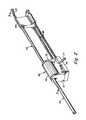
- FIG. 9is a perspective view of an alternate embodiment of the present invention, providing linear registration rather than rotational registration
- FIG. 10is a perspective view of another embodiment of a robotic surgical system in which the interchangeable instrument principles of the present invention are applied;
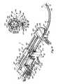
- FIG. 11is a perspective view at the slave station of the system of FIG. 10 illustrating the interchangeable instrument concepts
- FIG. 12is a cross-sectional view through the storage chamber and as taken along line 12 - 12 of FIG. 11 ;
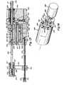
- FIG. 13is a longitudinal cross-sectional view, as taken along line 13 - 13 of FIG. 11 ;
- FIG. 14is a perspective schematic view of the indexing mechanism used in the embodiment illustrated in FIGS. 10-13 ;
- FIG. 15is a block diagram illustrating the steps taken to provide indexing for instrument interchange.
- FIG. 16is a schematic diagram of another alternate embodiment of the invention using a serial storage concept.
- the guide tubepreferably extends to the operative site OS (see FIG. 7 ) so that the instrument can transition safely thereto. Also, the guide tube preferably remains at the operative site even as the instruments are exchanged in the guide tube, so as to avoid any tissue or organ damage during an instrument exchange.
- the operative sitemay be defined as the general area in close proximity to where movement of the tool occurs in performing a surgical procedure, usually in the viewing area of the endoscope and away from the incision.
- instrument interchange principlesare illustrated in association with two separate surgical systems, both of which are robotic systems, sometimes also referred to as telerobotic systems.
- robotic systemssometimes also referred to as telerobotic systems.
- principles of this inventionalso apply to other surgical instrumentation, such as used in minimally invasive surgery (MIS), where a number of instrument exchanges are typical in performing a medical or surgical procedure.
- MISminimally invasive surgery
- FIGS. 1 through 8A and 8 Ba system is disclosed in FIGS. 10-14 .
- FIG. 9A variation of the first system is illustrated in FIG. 9 .
- the driverhas only linear translation while the instrument storage chamber rotates ( FIGS. 1 and 10 ) or slides ( FIG. 9 ).
- the drivermay rotate or otherwise move to different registration positions, as the instrument storage chamber remains stationary, as long as there is relative motion between the instrument driver and instrument storage chamber.
- FIG. 1shows a surgical instrument system 10 that performs surgical procedures.
- the systemmay be used to perform minimally invasive procedures.
- the systemmay also be used to perform open or endoscopic surgical procedures.
- the system 10includes a surgeon interface 11 , computation system 12 , and drive unit 13 .
- the systemcontrols the instrument so as to position the end effector (tool) 18 of the instrument 20 at the very distal end of and extending through the outlet guide tube 24 .
- a surgeonmay manipulate the handles 30 of the surgeon interface 11 , to effect desired motion of the end effector 18 within the patient, at the operative site which is schematically illustrated in FIG. 7 .
- the movement of a handle 30is interpreted by the computation system 12 to control the movement of the end effector (tool) 18 .
- the systemmay also include an endoscope with a camera to remotely view the operative site.
- the cameramay be mounted on the distal end of the instrument, or may be positioned away from the site to provide additional perspective on the surgical operation. In certain situations, it may be desirable to provide the endoscope through an opening other than the one used by the instrument.
- the entire assembly illustrated in FIG. 1is shown supported over the surgical table 27 , and in a position so that the guide tube 24 can be inserted through an incision in the patient and directed to the operative site of the patient.
- the incisionis represented in FIG. 1 by the dashed line L.
- the surgical instrument system 10 of the present inventionis preferably mounted on rigid post 19 which may be movably affixed to the surgical table 27 , at bracket 28 .
- the surgical system 10includes two mechanical cable-in-conduit bundles 21 and 22 . These cable bundles 21 and 22 terminate at one end at the two connection modules (couplers) 23 A and 23 B, which removably attach to the drive unit 13 .
- the drive unit 13is preferably located outside the sterile field, although it may be draped with a sterile barrier so that it may be operated within the sterile field.
- the other end of the bundlesterminate at the surgical system 10 .
- These terminationsare shown in further detail in the description of the second embodiment that is described later.
- cables in the bundle 21may control; the indexing for controlled rotation of the instrument storage chamber 40 ; rotation of the guide tube 24 ; as well as motion of the carriage 54 for control of the linear translation of the driver 50 .
- the bundle 22may control, for example, rotation of the instrument within the guide tube 24 , as well as actuation of the tool 18 .
- the instrument storage chamberis also referred to herein as an instrument retainer.
- FIG. 1also shows the instrument storage chamber 40 that is illustrated as supported over the base piece 51 , which, in turn, is supported from the rigid post 19 .
- the cable bundle 21couples to the base piece 51 and controls motion of the instrument storage chamber 40 , as well as the driver 50 .
- the guide tube 24is supported at the outlet port side of the instrument storage chamber 40 , and is controlled for rotation relative to the instrument storage chamber 40 . Rotation of the guide tube 24 provides a corresponding rotation of the instrument and tool.
- the instrument storage chamber 40has at its inlet side a port for receiving the driver 50 , and for permitting engagement of the driver with the one of the instruments in the instrument storage chamber 40 that is in registration with the driver 50 .
- the driver 50is supported from the carriage 54 which transitions on rails 55 , and is controlled from cable bundle 22 .
- the drivermay also be referred to herein as an instrument transporter.
- the guide tube 24 of the surgical instrument system 10is inserted into the patient usually through an incision. Usually, a cannula is positioned in the incision, is maintained in position and receives the guide tube 24 . This incision is illustrated in FIG. 1 by the dashed line L.
- the systemis then mounted to the rigid post 19 .
- the cable bundles 21 and 22are then coupled to the drive unit 13 .
- the connection modules or couplers 23 A and 23 B at the end of respective cable bundles 21 and 22are then engaged into the drive unit 13 .
- the systemis then ready for use and control from the master station side at surgeon interface 11 .
- the entire slave side of the systemincluding the drive unit, detachability at the drive unit, the cabling and cable couplers, refer to U.S. Ser. Nos. 09/783,637; and 10/014,143, previously mentioned.
- FIG. 7illustrates schematically a cabling scheme that may be used in the instrument.
- FIG. 9illustrates an alterative to the revolving chamber construction, in the form of a linearly translatable housing or chamber arrangement.
- the revolving instrument storage chamber 40includes a base 42 , opposite end walls 43 and a cylindrical chamber or magazine 44 .
- chamber 44has six elongated passages 46 each for receiving an instrument.
- the chamber 44is supported by a centrally disposed support rod 47 , such as illustrated in FIG. 5 .
- the support rod 47may be supported in bearings (not shown) at the opposite end walls 43 .
- the instrument storage chamber 40has its rotation controlled at base piece 51 (see FIG. 1 ) so that when an operator at interface 11 wants to change instruments, a command can be sent from the master to the slave side to rotate the magazine 44 so that a different instrument is in alignment with the driver 50 .
- this exchangeonly occurs when the driver has been withdrawn to its rest (disengaged) position. Specific sequences of the interchange action are described later.
- the command that is sentmay be initiated by any one of several means, some of which are described in some detail later.
- FIGS. 2 and 3also illustrate the outlet guide tube 24 .
- the tube 24is secured to one of the end walls 43 and is essentially fixed in axial position relative to that end wall 43 of the rotating instrument storage chamber 40 , but is capable of rotation on its own axis, and relative to the chamber 40 . Details of this rotational support are described further in connection with the second embodiment described in FIGS. 10-14 .
- the end walls 43 supporting the magazine 44are fixed to the base 42 , which is supported over the base piece 51 which, in turn, is fixed to the rigid post 19 .
- the instrument storage chamber 40rotates but does not have any significant linear movement toward or away from the operative site.
- the instrument controlhas a somewhat limited number of degrees-of-freedom. The degrees-of-freedom can be increased by providing the guide tube with a curved distal end, like that illustrated in the second embodiment of the invention in FIGS. 10-14 .
- FIGS. 1 through 6also illustrates the instrument driver 50 .
- the instrument driver 50is adapted to enter an end inlet port 49 in the wall 43 of the rotating chamber 40 .
- FIG. 3for the inlet port 49 .
- in the base piece 51there is an indexing mechanism that controls the rotation of the rotating storage chamber 44 so that different ones of the passages 46 are adapted to be aligned with the input driver port 49 .
- This registration controlmay be carried out using a detent mechanism so that the proper instrument is aligned and selected from the chamber by the instrument driver 50 .
- FIG. 14for an example of an indexing mechanism.
- an outlet port 48such as illustrated in FIG. 3 , and that aligns with the outlet guide tube 24 .
- the carriage 54that carries the instrument driver 50 and that transitions along the support rails 55 to enable the driver to selectively engage with and drive the instrument forward through the guide tube 24 and toward the operative site.
- FIG. 3illustrates a cross-sectional view of one embodiment of the interchangeable instrument apparatus of the present invention.
- An instrument 20 with its end effector (tool) 18is illustrated disposed in one of the elongated chambers 46 of the rotating chamber 44 .
- each of the other passages 46can contain other types of instruments, with a variety of different tool or end effectors.
- only one of the instrumentsis illustrated in FIG. 3 , it being understood that up to six other instruments of different types may be disposed in other ones of the elongated passages 46 .
- the magazine 44may be constructed with fewer or more instrument-receiving passages.
- FIG. 3also illustrates the driver 50 in a position where the end 56 thereof is positioned just entering the inlet port 49 with the end 56 about to engage the end 25 of the instrument 20 .
- the position of the instrument driver 50is considered as a “rest position” when the end 57 is disposed in wall 43 , but has not yet entered the magazine 44 so that the magazine 44 is free to rotate.
- a post 58(see FIG. 5 ) on the driver 50 and an accommodating recess 26 (see FIG. 5 ) in the instrument end 25 .
- FIG. 1there are mechanical cables extending in bundles 21 and 22 illustrated in FIG. 1 .
- the cables in bundle 22couple by way of pulleys and then extend the length of the driver 50 to the instrument 20 .
- the cabling and control pulley arrangementsare disclosed in further detail in the second embodiment as shown in FIGS. 10-14 .
- This cablingis for operating the end effector 18 illustrated in FIG. 1 .
- both the instrument driver as well as the instrumentcarry interconnecting cable connections. These are illustrated clearly in FIGS. 4 through 6 . Also refer to the schematic perspective view of FIG. 7 showing the manner in which the cables couple about pulleys 29 and extend through the driver to intercouple with cabling of the instrument 20 .
- driver and instrumentmay also be considered as defining a coupling section or coupling interface 59 where the driver and instrument are releasably engageable.
- driver and instrumentsuch as illustrated in FIGS. 1-6 , as collectively being an instrument member including a work section (instrument 20 and tool 18 ), and a driver section (driver 50 ).
- the instrument driver 50has passages 61 (see FIG. 4 ) for receiving a cable 62 (see FIGS. 4 , 5 and 6 ). As illustrated in FIGS. 4 , 5 and 6 the end of cable 62 terminates in a hook 64 .
- the hook 64is adapted to engage with a similar-configuration hook 66 at the end of cable 68 as illustrated in FIG. 6 .
- FIG. 4illustrates a series of slots or passages 61 , which in the illustrated embodiment comprise six such slots 61 . Each of these slots receives a cable 62 with its end hook 64 .
- FIG. 4this illustrates the end 25 of the instrument 20 . Also illustrated are the elongated slots 61 in the driver (transporter) 50 . FIG. 4 illustrates the cables 68 and their associated hooks 66 associated with the instrument 20 . Also shown is the cable 62 with its hook 64 disposed in slot 61 .
- FIG. 5illustrates the end 56 of the instrument driver 50 as the driver 50 is transitioning through the port 49 for engagement with the instrument 20 .
- the driver 50has not yet engaged the instrument 20 , but has just left its rest position.
- the “rest” (disengaged) position for the instrument driver 50is one in which the end 56 of the driver 50 is disposed in the end wall 43 and out of the passage 46 so that the chamber 44 is free to rotate.
- the hook 66 associated with the instrument 20is preferably biased to a somewhat outward deflected position.
- the passage 46has an enlarged section 46 A that permits the hook 66 to deflect outwardly, as illustrated.
- the hooksare essentially spring biased outwardly so as to contact the inner wall surface of enlarged section 46 A. This enables the driver to pass by the hooks 66 for engagement with the instrument 20 .
- the hook 64passes under the hook 66 and as the driver is driven further to the left, as viewed in FIG. 3 , the hooks 64 and 66 become interlocked in the position illustrated in FIG. 6 and there is thus cable continuity from cable 62 to cable 68 .
- the operation of these cablesprovide operation of certain actions of the end effector 18 .
- the driver end 56engages the instrument end 25
- the post 58engages with the recess 26 so as to properly align the driver and instrument.
- the hooks 66are still out of engagement with the hooks 64 .
- the instrumentstarts to transition out of the storage chamber passage 46 , and the hooks 66 transition into the smaller diameter section of the passage 46 , causing them to deflect into engagement with the hooks 64 , such as illustrated in FIG. 6 .
- the coupling interface 59 formed essentially between the hooks 64 and 66is maintained as the instrument transitions out of the instrument storage chamber 40 . Refer to FIG. 7 .
- the driver 50is of a sufficient length so that the selected instrument 20 is driven out of the chamber 44 and into the outlet guide tube 24 .
- the instrumentis then transitioned through the guide tube 24 to the position illustrated in FIG. 1 where the end effector or tool 18 of the instrument extends from the distal end of the guide tube 24 at a position inside the body cavity (operative site). All the while that the instrument is being transitioned to the end of the guide tube 24 , the interconnecting cables are maintained in an interlocked position such as illustrated by the engaged hooks 64 and 66 in FIG. 6 .
- the driver 50When it is desired to change to a different instrument, the driver 50 is withdrawn or in other words is moved in a direction to the right in FIG. 3 .
- Thiscarries the instrument with the instrument driver to the right and when the instrument reaches a position approximately as illustrated in FIG. 5 , because of the increased diameter of the section 46 A illustrated in FIG. 5 , the hooks 66 are biased outwardly and disengage from the hooks 64 .
- Thisessentially disengages the driver from the instrument and the driver is then in a position to be withdrawn through the port 49 , no longer engaging with the instrument. This also leaves the instrument 20 in place in the instrument storage chamber 44 in readiness for a subsequent usage.
- the instrument storage chambercan then be rotated to align a different instrument with the driver.
- the cabling in bundle 21via base piece 51 , controls the position of chamber 40 so as to select a different instrument by rotating the chamber 44 so that a different instrument registers with the driver 50 .
- a different instrumentwould also carry cabling similar to that illustrated in FIG. 5 .
- Tool 18may include a variety of articulated tools, such as jaws, scissors, graspers, needle holders, micro dissectors, staple appliers, tackers, suction irrigation tools, clip appliers, that have end effectors driven by wire links, eccentric cams, push-rods or other mechanisms.
- tool 18may comprise a non-articulated instrument, such as cutting blades, probes, irrigators, catheters or suction orifices.
- tool 18may comprise an electrosurgical probe for ablating, resecting, cutting or coagulating tissue.
- interlocking surfacessuch as a tongue and groove (not shown) between the walls of the chamber passage and the outer surface off the instrument and/or driver.
- Interlocking or guiding surfacesmay also be provided within the guide tube 24 .
- FIG. 7illustrates the driver 50 in a position in which it has entered the guide tube 24 and transitions to a location essentially at the end of the guide tube where the tool 18 is located and at the operative site OS.
- the coupling or interface section 59At the end of the driver where the cable hooks engage, such as illustrated in FIGS. 5 and 6 , there is the coupling or interface section 59 .
- FIG. 7also illustrates the passages 46 and another non-selected tool within the instrument storage chamber.
- FIGS. 8A and 8BThe construction of one form of tool is illustrated in FIGS. 8A and 8B .
- Thisis in the form of a set of jaws or grippers. This tool is shown for the purpose of illustration, it being understood that a variety of other tool may be used.
- FIG. 8Ais a perspective view showing the tool pivoted at the wrist while FIG. 8B is an exploded view of the tool.
- the tool 18is comprised of four members including the base 600 , link 601 , upper grip or jaw 602 and lower grip or jaw 603 .
- the base 600is affixed to the flexible stem section 302 .
- This flexible sectionmay be constructed of a ribbed plastic. This flexible section may be used when a curved end guide tube (see FIG. 11 ) is used so that the instrument will readily bend through the curved actuator tube 24 .
- FIG. 8Billustrates a pivot pin at 620 .
- the upper and lower jaws 602 and 603are rotatably connected to the link about axis 605 , where axis 605 is essentially perpendicular to axis 604 .
- FIG. 8Billustrates another pivot pin at 624 .
- Cable 606 - 611shown schematically in FIG. 8A and FIG. 8B , actuate the four members 600 - 603 of the tool.
- Cable 606travels through the insert stem (section 302 ) and through a hole in the base 600 , wraps around curved surface 626 on link 601 , and then attaches on link 601 at 630 .
- Tension on cable 606rotates the link 601 , and attached upper and lower grips 602 and 603 , about axis 604 (wrist pivot).
- Cable 607provides the opposing action to cable 606 , and goes through the same routing pathway, but on the opposite sides of the insert. Cable 607 may also attach to link 601 generally at 630 . Cables 606 and 607 may be one continuous cable secured at 630 .
- Cables 608 and 610also travel through the stem 302 and though holes in the base 600 .
- the cables 608 and 610then pass between two fixed posts 612 . These posts constrain the cables to pass substantially through the axis 604 , which defines rotation of the link 601 .
- This constructionessentially allows free rotation of the link 601 with minimal length changes in cables 608 - 611 .
- the cables 608 - 611which actuate the grips 602 and 623 , are essentially decoupled from the motion of link 601 .
- Cables 608 and 610pass over rounded sections and terminate on grips 602 and 603 , respectively. Tension on cables 608 and 610 rotate grips 602 and 603 counter-clockwise about axis 605 .
- the cables 609 and 611pass through the same routing pathway as cables 608 and 610 , but on the opposite side of the instrument. These cables 609 and 611 provide the clockwise motion to grips or jaws 602 and 603 , respectively. At the jaws 602 and 603 , as depicted in FIG. 8B , the ends of cables 608 - 611 may be secured at 635 . This securing may occur with the use of an adhesive such as an epoxy glue or the cables could be crimped to the jaw.
- FIG. 9schematically illustrated an alternate embodiment of the present invention.
- the different instrumentsare selected by means of a rotating arrangement.
- the selectionis made on an essentially linear basis.
- a flat array 70also having a series of elongated passages 72 extending therethrough. Each of these passages accommodates an instrument.
- FIG. 9also schematically illustrates, by the same reference characters, the instrument driver 50 and the outlet guide tube 24 such as previously illustrated in FIGS. 1-8 .
- the flat array 70may be driven selectively in the direction of arrow 74 so as to align different ones of the passages 72 with the driver 50 and guide tube 24 .
- Mechanisms for selective linear driveare well known, as are mechanisms for registration so as to provide proper alignment between the instrument and instrument driver.
- the interchange systemis designed preferably to have all cabling maintained in tension. In this way, as an instrument is engaged, all of the cabling running therethrough is in tension and properly operative to control the end effector whether it be a set of jaws as illustrated in FIGS. 8A and 8B or some other type of instrument. If an end effector has less degrees of movement than that illustrated in FIGS. 8A and 8B this is still effectively controlled, but with the use of fewer cable control signals (fewer cables will actually be activated).
- FIGS. 10-14Reference is now made to the second robotic surgical system depicted in FIGS. 10-14 , and that discloses a system having a greater number of degrees-of-freedom than the system described in FIGS. 1-8 .
- FIGS. 10-14the same reference characters are used for similar components as depicted in FIGS. 1-8 .
- FIG. 10illustrates a surgical instrument system 10 that includes a master station M at which a surgeon 2 manipulates an input device, and a slave station S at which is disposed a surgical instrument.
- the input deviceis illustrated at 3 being manipulated by the hand or hands of the surgeon.
- the surgeonis illustrated as seated in a comfortable chair 4 .
- the forearms of the surgeonare typically resting upon armrests 5 .
- FIG. 10illustrates a master assembly 7 associated with the master station M and a slave assembly 8 associated with the slave station S.
- Assembly 8may also be referred to as a drive unit.
- Assemblies 7 and 8are interconnected by means of cabling 6 with a controller 9 .
- controller 9typically has associated therewith one or more displays and a keyboard. Reference is also made to, for example, the aforementioned U.S. Ser. No. 10/014,143, for further detailed descriptions of the robotic controller operation and associated algorithm.
- the drive unit 8is remote from the operative site and is preferably positioned a distance away from the sterile field.
- the drive unit 8is controlled by a computer system, part of the controller 9 .
- the master station Mmay also be referred to as a user interface vis-vis the controller 9 . Commands issued at the user interface are translated by the computer into an electronically driven motion in the drive unit 8 .
- the surgical instrumentwhich is tethered to the drive unit through the cabling connections, produces the desired replicated motion.
- FIG. 10also illustrates an operating table T upon which the patient P is placed.
- the controllercouples between the master station M and the slave station S and is operated in accordance with a computer algorithm.
- the controllerreceives a command from the input device 3 and controls the movement of the surgical instrument so as to replicate the input manipulation.
- the surgical instrument 14which in the illustrated embodiment actually comprises two separate instruments one on either side of an endoscope E.
- the endoscopeincludes a camera to remotely view the operative site.
- the cameramay be mounted on the distal end of the instrument insert, or may be positioned away from the site to provide additional perspective on the surgical operation.
- FIG. 10three separate incisions are shown, two for accommodating the surgical instruments and a centrally disposed incision that accommodates the viewing endoscope.
- a drapeis also shown with a single opening.
- the surgical instrument 14is generally comprised of two basic components including a surgical adaptor or guide 15 and an instrument 14 .
- FIG. 10illustrates the surgical adaptor 15 , which is comprised primarily of the guide tube 24 .
- the instrument 14is not clearly illustrated but extends through the guide tube 24 .
- the instrument 14carries at its distal end the tool 18 . Descriptions of the surgical instrument are found hereinafter in additional drawings, particularly FIG. 11 .
- the surgical adaptor 15is basically a passive mechanical device, driven by the attached cable array.
- FIG. 10there is illustrated cabling 22 coupling from the instrument 14 to the drive unit 18 .
- the cabling 22is preferably detachable from the drive unit 8 .
- the surgical adaptor 15may be of relatively simple construction. It may thus be designed for particular surgical applications such as abdominal, cardiac, spinal, arthroscopic, sinus, neural, etc.
- the instrument 14couples to the adaptor 15 and essentially provides a means for exchanging the instrument tools.
- the toolsmay include, for example, forceps, scissors, needle drivers, electrocautery etc.
- the surgical system 10may preferably be used to perform minimally invasive procedures, although it is to be understood that the system may also be used to perform other procedures, such as open or endoscopic surgical procedures.
- the system 10includes a surgeon's interface 11 , computation system or controller 9 , drive unit 8 and the surgical instrument 14 .
- the surgical system 10is comprised of an adaptor or guide 15 and the instrument 14 .
- the systemis used by positioning a tool 18 of the instrument, which is inserted through the surgical adaptor or guide 15 .
- a surgeonmay manipulate the input device 3 at the surgeon's interface 11 , to effect desired motion of the tool 18 within the patient.
- the movement of the handle or hand assembly at input device 3is interpreted by the controller 9 to control the movement of the guide tube 24 , instrument, and tool 18 .
- the surgical instrument 14along with the guide tube 24 is mounted on a rigid post 19 which is illustrated in FIG. 10 as removably affixed to the surgical table T.
- This mounting arrangementpermits the instrument to remain fixed relative to the patient even if the table is repositioned.
- FIG. 10there are illustrated two such instruments, even a single surgical instrument may be used.
- cablingsAs indicated previously, connecting between the surgical instrument 14 and the drive unit 8 , are cablings. These include two mechanical cable-in-conduit bundles 21 and 22 . These cable bundles 21 and 22 may terminate at two connection modules, not illustrated in FIG. 10 (see FIG. 1 ), which removably attach to the drive unit 8 . Although two cable bundles are described here, it is to be understood that more or fewer cable bundles may be used. Also, the drive unit 8 is preferably located outside the sterile field, although it may be draped with a sterile barrier so that it may be operated within the sterile field.
- the surgical instrument 14is inserted into the patient through an incision or opening.
- the instrument 14is then mounted to the rigid post 19 using a mounting bracket 31 .
- the cable bundles 21 and 22are then passed away from the operative area to the drive unit 8 .
- the connection modules of the cable bundlesare then engaged into the drive unit 8 .
- the separate instrument members of instrument 14are then selectively passed through the guide tube 24 . This action is in accordance with the interchangeable instrument concepts of this invention.
- the instrument 14is controlled by the input device 3 , which is be manipulated by the surgeon. Movement of the hand assembly produces proportional movement of the instrument 14 through the coordinating action of the controller 9 . It is typical for the movement of a single hand control to control movement of a single instrument.
- FIG. 10shows a second input device that is used to control an additional instrument. Accordingly, in FIG. 10 two input devices are illustrated and two corresponding instruments. These input devices are usually for left and right hand control by the surgeon.
- the surgeon's interface 11is in electrical communication with the controller 9 .
- This electrical controlis primarily by way of the cabling 6 illustrated in FIG. 10 coupling from the bottom of the master assembly 7 .
- Cabling 6also couples from the controller 9 to the actuation or drive unit 8 .
- This cabling 6is electrical cabling.
- the actuation or drive unit 8is in mechanical communication with the instrument 14 .
- the mechanical communication with the instrumentallows the electromechanical components to be removed from the operative region, and preferably from the sterile field.
- the surgical instrument 14provides a number of independent motions, or degrees-of-freedom, to the tool 18 . These degrees-of-freedom are provided by both the guide tube 24 and the instrument 14 .
- FIG. 10shows primarily the overall surgical system.
- FIGS. 11-14show further details particularly of the interchangeable instrument concepts as applied to this system.
- FIG. 15illustrates a control algorithm for the system.
- the system of FIG. 10is adapted to provide seven degrees-of-freedom at the tool 18 . Three of the degrees-of-freedom are provided by motions of the adaptor 15 , while four degrees-of-freedom may be provided by motions of the instrument 14 .
- the adaptoris remotely controllable so that it pivots, translates linearly, and has its guide tube rotate. The instrument also rotates (through the instrument driver), pivots at its wrist, and has two jaw motions at the tool.
- FIG. 11is a perspective view at the slave station of the system of FIG. 10 illustrating the interchangeable instrument concepts.
- FIG. 12is a cross-sectional view through the storage chamber and as taken along line 12 - 12 of FIG. 11 .
- FIG. 13is a longitudinal cross-sectional view, as taken along line 13 - 13 of FIG. 11 .
- FIG. 14is a perspective schematic view of the indexing and registration mechanism used in the embodiment illustrated in FIGS. 10-13 .
- FIG. 11is a perspective view illustrating the instrument 14 and the adaptor 15 at the slave station S.
- This instrument systemis secured in the manner illustrated in FIG. 10 to the rigid post 19 that supports the surgical instrument by way of the mounting bracket 31 illustrated in FIG. 10 , but not shown in FIG. 11 .
- FIG. 11also shows several cables that may be separated into five sets for controlling different motions and actions at the slave station. These are individual cables of the aforementioned bundles 21 and 22 referred to in FIG. 10 .
- FIG. 11also illustrates the support yoke 220 that is secured to the mounting bracket 31 , the pivot piece 222 , and support rails 224 for the carriage 226 .
- the railsare supported in end pieces 241 and 262 with the end piece 241 attached to the pivot piece 222 .
- the pivot piece 222pivots relative to the support yoke 220 about pivot pin 225 .
- a base piece 234is supported under the carriage 226 by means of the support post 228 .
- the support post 228in essence supports the entire instrument assembly, including the adaptor 15 and the instrument 14 .
- the support yoke 220is supported in a fixed position from the mounting bracket 31 .
- the support yoke 220may be considered as having an upper leg 236 and a lower leg 238 .
- the pivot piece 222In the opening 239 between these legs 236 and 238 is arranged the pivot piece 222 .
- Cablingextends into the support yoke 220 .
- Thisis illustrated in FIG. 11 by the cable set 501 .
- Associated with the pivot piece 222 and the carriage 226are pulleys (not shown) that receive the cabling for control of two degrees-of-freedom.
- This control from the cable set 501includes pivoting of the entire instrument assembly about the pivot pin 225 . This action pivots the guide tube 24 essentially in a single plane.
- This pivotingis preferably about an incision of the patient which is placed directly under, and in line with, the pivot pin 225 .
- Other cables of set 501control the carriage 226 in a linear path in the direction of the arrow 227 . See also the cables 229 extending between the carriage 226 and the end pieces 241 and 262 .
- the carriagemoves the instrument and guide tube 24 back and forth in the direction of the operative site OS. Incidentally, in FIG. 11 the instrument is in its fully advanced state with the tool at the operative site OS.
- the base piece 234is the main support for the interchangeable instrument apparatus of the invention. Refer to FIGS. 11-14 .
- the base piece 234supports the guide tube 24 , the instrument storage chamber 540 , and the instrument driver 550 .
- the instrument driver 550is supported from another carriage, depicted in FIGS. 11 and 13 as the carriage 552 , and that, in turn, is supported for translation on the carriage rails 554 .
- the rails 554are supported at opposite ends at end pieces 556 and 558 , in a manner similar to the support for the other carriage 226 .
- a support post 560interconnects the carriage 552 with the instrument driver housing 570 .
- FIG. 11depicts four other cable sets 503 , 505 , 507 , and 509 .
- Cable set 503controls rotation of the guide tube 24 .
- Cable set 505controls the carriage 552 , and, in turn, the extending and retracting of the instrument driver for instrument exchange.
- Cable set 507controls rotation of the instrument through rotation of the instrument driver.
- cable set 509controls the tool via the instrument driver and instrument.
- FIG. 13shows a cross-sectional view through the interchangeable instrument portion of the overall instrument system. This clearly illustrates the internal cable and pulley arrangement for the various motion controls. There is a pulley 301 driven from the cable set 503 that controls rotation of the guide tube 24 . There is also a pulley 303 driven from cable set 505 , along with a companion pulley 305 that provides control for the carriage 552 . FIG. 13 also illustrates another pulley 307 driven from cable set 507 , and for controlling the rotation of the instrument driver 550 , and, in turn, the selected instrument.
- FIG. 13illustrates the guide tube 24 supported from the base piece 234 .
- the guide tube 24is hollow and is adapted to receive the individual instruments or work sections 541 disposed in the instrument storage chamber 540 , as well as the instrument driver 550 .
- FIG. 7for an illustration of the instrument and instrument driver positioned in the guide tube 24 .
- FIG. 13shows the instrument driver 550 in its rest or disengaged position.
- the proximal end 24 A of the guide tube 24is supported in the base piece 234 by means of a pair of bearings 235 so that the guide tube 24 is free to rotate in the base piece 234 . This rotation is controlled from the pulley 237 which is secured to the outer surface of the guide tube 24 by means of a set screw 231 .
- the pulley 237is controlled to rotate by means of the cabling 310 that intercouples the pulleys 301 and 237 and that is an extension of the cabling 503 .
- the rotational position of the guide tube 24is controlled from cable set 503 .
- this controlled rotationis effected from the master station via the controller 9 , as depicted in the system view of FIG. 10 , and as a function of the movements made by the surgeon at the user interface 11 .
- the proximal end 24 A of the guide tube 24is supported from the base piece 234 .
- the distal end of the guide tube 24which is adapted to extend through the patient incision, and is disposed at the operative site OS illustrated about the tool 18 in FIG. 11 , and where a medical or surgical procedure is to be performed.
- the distal end of the guide tube 24is curved at 24 B. In this way by rotating the guide tube 24 about its longitudinal axis there is provided a further degree-of-freedom so as to place the end tool at any position in three-dimensional space. The rotation of the guide tube 24 enables an orbiting of the end tool about the axis of the guide tube 24 .
- the guide tube 24is preferably rigid and constructed of a metal such as aluminum.
- the tool 18 illustrated in FIG. 11may be the same tool as illustrated in FIGS. 8A and 8B . Also, when the instrument is fully engaged, as in FIG. 11 , the cabling and cable interface is as illustrated in FIG. 7 .
- FIG. 13also illustrates a cross-section of the instrument storage chamber 540 including the storage magazine 549 , and showing two of the six instrument passages 542 in the storage magazine 549 .
- the instrument storage chambermay also be referred to herein as an instrument retainer.
- one of the instruments 541is about to be engaged by the instrument driver 550 .
- the other instrument 541is in place (storage or rest position) in the instrument storage chamber 540 , and out of the path of the instrument driver 550 .
- One of the instruments 541carries a gripper tool illustrated at 543 , while the other instrument carries a scissors 544 . Because these instruments are adapted to pass to the guide tube 24 and be positioned at the distal end 24 B thereof, the body 548 of the instrument is flexible so as to be able to curve with the curvature of the guide tube 24 .
- instrument driver 550As a “driver section” of the overall one piece instrument member, and the instrument 541 as a “working” section of the instrument member.
- the instrument memberhas also been previously discussed as having a “coupling section” or “interface section”, which is defined between the working section and the driver section where the cables interlock by means of the engaging hook arrangement, such as clearly depicted in FIGS. 5 and 6 . This is shown in FIG. 13 at 559 . This is analogous to the interface 59 illustrated in FIG. 7 .
- the carriage 552 illustrated in FIG. 13is moved linearly by the cables 555 that extend between pulleys 303 and 305 . These cables attach to the carriage 552 .
- the carriage movementis controlled from cable set 505 . It is the movement of the carriage 552 that drives the instrument driver (driver section) 550 .
- the instrument driver 550in its rest or disengaged position, is supported between the instrument driver housing 570 and the wall 562 that is used for support of the instrument storage chamber 540 .
- the instrument magazine 549is rotationally supported by means of the axle or shaft 547 , with the use of bushings or bearings, not shown. This support is between walls 562 and 563 .
- FIG. 13shows the very distal end 525 of the instrument driver (transporter) 550 supported at wall 562 .
- the driverIn the rest position of the instrument driver 550 the driver is out of engagement with the instruments and the magazine 549 , thus permitting rotation of the instrument storage chamber 540 .
- the proximal end 526 of the instrument driver 550is supported at the instrument driver housing 570 . It may be rotationally supported by means of a bushing 527 .
- the instrument driver 550is supported for rotation, but rotation is only enabled once the driver has engaged the instrument and preferably is at the operative site. The rotation of the instrument driver 550 is controlled from cable set 503 by way of the pulley 307 .
- the cable set 509is illustrated as controlling the instrument motions including tool actuation.
- These cablescontrol a series of pulleys shown in FIG. 13 as pulleys 529 .
- these pulleyscontrol cabling that extends through the instrument driver and the instrument for control of instrument and tool motions.
- the cables that are controlled from these pulleysmay control three degrees-of-freedom of the instrument, including pivoting at the wrist and two for gripper action.
- FIGS. 5 and 6For the details of the interlocking of the instrument and instrument driver refer to FIGS. 5 and 6 .
- the same engagement arrangementcan be used in this second embodiment of the invention including the mating hook arrangement, interlocked at interface 559 when the instrument driver and instrument are engaged.
- the indexing motor 565is illustrated in FIG. 11 positioned next to the base piece 234 , and is further illustrated in FIG. 14 located for interaction with the instrument storage chamber 540 .
- the indexing motor 565is controlled from the master station side, and accordingly there is another cable set (not shown) that actuates the indexing motor 565 .
- the indexing motor 565may be a stepper motor having a degree of rotation that corresponds to the desired rotation of the instrument storage chamber 540 .
- the stepper motormay be designed to provide 60 degrees of rotation for each actuation, corresponding to an instrument storage chamber 540 having six passages (360 degrees divided by 6) for receiving instruments.
- the stepper motor 565has an output shaft 566 that supports an indexing disk 567 , shown also in dashed line in FIG. 12 .
- the indexing disk 567is fixed to the shaft 566 and so rotates with the shaft 566 .
- FIG. 12illustrates the disk 567 carrying four pins 568 disposed at the periphery of the disk 567 .
- FIG. 14also shows these pins 568 .
- the pins 568selectively engage in indexing slots 569 in an end wall of the magazine 549 .
- a spring and ball detent arrangementis employed. Refer to FIGS. 11-14 illustrating a standard ball and spring member 575 supported in the wall 563 .
- the ball of member 575is urged against an end wall surface 576 of the magazine 549 .
- This end wallhas a series of detent dimples 577 (see FIG. 14 ) disposed at locations corresponding to the passages in the magazine 549 .
- the stepper motor 565is selectively operated under surgeon control from the master station. Each step rotates the disk 567 through 90 degrees. The engagement of the pins 568 with the slots 569 causes a corresponding rotation of the magazine 549 through 60 degrees. Each subsequent rotation of the stepper motor 565 causes a further 60 degree rotation of the magazine 549 .
- the stepper motor 565is controllable in a manner so that, with proper decoding, there may be multiple step actuations to get from one instrument to the next selected instrument.
- the operation of the slave instrumentis in a robotic manner from the master station, such as illustrated in FIG. 10 .
- the surgeoncan control several degrees-of-freedom of the instrument system.
- thiscan be done directly from the master station from an actuation member and at the proper time in the surgical procedure.
- One type of actuation membermay be by means of a foot switch 410 illustrated in FIG. 10 within access of the surgeon.
- the foot switch 410couples to the controller 9 .
- Appropriate electrical signalsare coupled from the master station to the slave station basically to control the stepper motor 565 for indexing the magazine 549 .
- FIG. 15The sequence of operation for the indexing is demonstrated in the flow chart of FIG. 15 .
- This block diagramindicates the sequence of steps performed commencing with a rest position of the system in which the instruments are all in place in the storage chamber 540 , and the instrument driver is in the position substantially as illustrated in FIG. 13 , just out of contact with the registered instrument and with the driver end 525 disposed in the wall 562 . It is this position that is illustrated in FIG. 15 by box 420 .
- the next stepis to check the registration of the instrument driver with the instrument itself. This is depicted by the box 422 .
- This stepmay involve the use of some known registration system, such as one using an optical sensing arrangement to determine proper registration between the instrument driver 550 and each of the passages in the magazine 549 , along with the instrument 541 . If proper registration is detected then the system proceeds to the next step indicated in FIG. 15 by box 426 , which activates the instrument driver 550 . This starts the process of driving the instrument to the operative site OS. This involves mechanical control signals on the cable set 505 controlling the carriage 552 , and in turn, the instrument driver 550 . If an improper registration is detected then box 424 indicates the step of correcting the registration. This may be carried out in a well known manner with the use of an optical system to provide slight rotation to the instrument storage chamber 540 so as to obtain proper registration. This system may also use some type of a feedback system.
- some known registration systemsuch as one using an optical sensing arrangement to determine proper registration between the instrument driver 550 and each of the passages in the magazine 549 , along with the instrument 541 . If proper registration is detected then the system proceeds to
- the next step in the systemis indicated in FIG. 15 by the box 428 which simply detects the fully engaged position of the instrument driver and instrument. This is the position illustrated in FIG. 11 . Again, this position can be readily detected by optical means.
- the next step illustrated in FIG. 15 by box 430is one that commences the interchange process. The intercoupled instrument and instrument driver are withdrawn. This involved movement of the carriage 552 in the opposite direction.
- Next, indicated by box 432is where the instrument and instrument driver have reached the position illustrated in FIG. 13 previously referred to as the “rest position”. In that position the instrument driver (transporter) 550 is clear of the instrument storage chamber 540 , and thus the instrument storage chamber 540 can be indexed (rotated). This is shown in FIG. 15 by the box 434 .
- a foot switchcan be used, such as the switch 410 illustrated in FIG. 10 .
- the switch 410may be comprised of six separate actuation buttons, each one corresponding to one of the six instruments disposed in the instrument storage chamber 540 .
- Indiciamay be provided associated with the storage chamber to indicate what particular instrument is disposed in what particular instrument passage. In this way the surgeon would know what button to actuate to select the desired instrument.
- the control system for indexingmay also include a decoding scheme so that when the surgeon makes a selection the decoder determines the number of rotations (such as of the stepper motor 565 ) necessary to bring the instrument driver into proper registration with the selected instrument. Because it may not always be clear as to the specific instrument sequence that the surgeon will use, the system has to determine how to index from one instrument to the next one selected. This selection process involves more than just sequencing from one instrument to an adjacent instrument. The process will have to accommodate a selection process in which the next selected instrument is not the adjacent instrument. Thus a simple decoder can be used to determine the number of stepper motor steps necessary to move the storage chamber to the next selected instrument.
- FIG. 10Another aid that can be provided to the surgeon is a visible display illustrated in FIG. 10 , and on which there can be a diagram that matches the storage chamber pattern showing to the surgeon exactly where each instrument is placed including the type of instrument. This could be set up when the instruments are first selected the disposed in the instrument storage chamber 540 . In association with this display one could also provide, in place of the switch 410 , a voice activated system so that the surgeon simply indices by voice which instrument to select. This may be done by simply numbering the instruments, such as one through six. A further variation may use a touch screen so that the surgeon simply touches an area on the screen corresponding to the displayed image of the storage chamber with the stored instruments.
- the activating signals at the slave sidebasically control the stepper motor 565 via a cable set not specifically shown in the drawings but that would couple to the stepper motor 565 illustrated in FIGS. 11 , 12 and 14 .
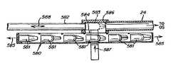
- FIG. 16for a schematic representation of a further alternate embodiment of the invention.
- the instrumentsare contained in a parallel array.
- the instrumentsmay also be disposed in a series array, as depicted in the schematic diagram of FIG. 16 .
- This embodimentincludes a retainer 580 that is adapted to store a series of instruments 581 in a serial array, also referred to herein as a linear chamber or linear retainer. Means are provided to enable the array to move laterally in the directions indicated by arrows 585 . This movement can be of either the retainer or the instruments themselves.
- surgical instrumentit is contemplated that the principles of this invention also apply to other medical instruments, not necessarily for surgery, and including, but not limited to, such other implements as catheters, as well as diagnostic and therapeutic instruments and implements.
- the coupling sections or interface sectionshave been disclosed as intercoupled cables with hook arrangements, such as shown in FIG. 6 .
- a different mechanical coupling schememay be employed using a different interlock between cables.
- other technologiesmay be used for coupling action to the instrument and tool, such as SMA technology.
- SMA technologyRegarding the tool itself, one has been illustrated with a wrist pivot. Instead the tool may include a bendable section at or near its distal end.
- stepper motorother indexing arrangements can be used, such as a ratchet and pawl system.
- encoderscan be used at the rotating storage chamber to detect motions to provide feedback for controlling the overall system.
Landscapes
- Health & Medical Sciences (AREA)
- Engineering & Computer Science (AREA)
- Life Sciences & Earth Sciences (AREA)
- Surgery (AREA)
- Robotics (AREA)
- Biomedical Technology (AREA)
- Nuclear Medicine, Radiotherapy & Molecular Imaging (AREA)
- Heart & Thoracic Surgery (AREA)
- Medical Informatics (AREA)
- Molecular Biology (AREA)
- Animal Behavior & Ethology (AREA)
- General Health & Medical Sciences (AREA)
- Public Health (AREA)
- Veterinary Medicine (AREA)
- Surgical Instruments (AREA)
Abstract
Description
Claims (9)
Priority Applications (2)
| Application Number | Priority Date | Filing Date | Title |
|---|---|---|---|
| US11/762,758US7901399B2 (en) | 1998-02-24 | 2007-06-13 | Interchangeable surgical instrument |
| US13/010,657US8303576B2 (en) | 1998-02-24 | 2011-01-20 | Interchangeable surgical instrument |
Applications Claiming Priority (13)
| Application Number | Priority Date | Filing Date | Title |
|---|---|---|---|
| US2855098A | 1998-02-24 | 1998-02-24 | |
| US13340799P | 1999-05-10 | 1999-05-10 | |
| US09/375,666US6197017B1 (en) | 1998-02-24 | 1999-08-17 | Articulated apparatus for telemanipulator system |
| US52750300A | 2000-03-16 | 2000-03-16 | |
| PCT/US2000/012553WO2000067640A2 (en) | 1999-05-10 | 2000-05-09 | Surgical instrument |
| US09/746,853US6692485B1 (en) | 1998-02-24 | 2000-12-21 | Articulated apparatus for telemanipulator system |
| US09/783,637US20010031983A1 (en) | 1999-05-10 | 2001-02-14 | Surgical instrument |
| US09/827,643US6554844B2 (en) | 1998-02-24 | 2001-04-06 | Surgical instrument |
| US09/827,503US6432112B2 (en) | 1998-02-24 | 2001-04-06 | Articulated apparatus for telemanipulator system |
| PCT/US2001/011376WO2002051329A1 (en) | 2000-12-21 | 2001-04-06 | Tendon actuated articulated members for a telemanipulator system |
| US10/034,871US6810281B2 (en) | 2000-12-21 | 2001-12-21 | Medical mapping system |
| US10/077,233US7297142B2 (en) | 1998-02-24 | 2002-02-15 | Interchangeable surgical instrument |
| US11/762,758US7901399B2 (en) | 1998-02-24 | 2007-06-13 | Interchangeable surgical instrument |
Related Parent Applications (12)
| Application Number | Title | Priority Date | Filing Date |
|---|---|---|---|
| US2855098AContinuation | 1998-02-24 | 1998-02-24 | |
| US09/375,666DivisionUS6197017B1 (en) | 1998-02-24 | 1999-08-17 | Articulated apparatus for telemanipulator system |
| US52750300AContinuation-In-Part | 1998-02-24 | 2000-03-16 | |
| PCT/US2000/012553ContinuationWO2000067640A2 (en) | 1998-02-24 | 2000-05-09 | Surgical instrument |
| US09/746,853Continuation-In-PartUS6692485B1 (en) | 1998-02-24 | 2000-12-21 | Articulated apparatus for telemanipulator system |
| US09/746,853ContinuationUS6692485B1 (en) | 1998-02-24 | 2000-12-21 | Articulated apparatus for telemanipulator system |
| US09/783,637Continuation-In-PartUS20010031983A1 (en) | 1998-02-24 | 2001-02-14 | Surgical instrument |
| PCT/US2001/011376Continuation-In-PartWO2002051329A1 (en) | 1998-02-24 | 2001-04-06 | Tendon actuated articulated members for a telemanipulator system |
| US09/827,503Continuation-In-PartUS6432112B2 (en) | 1998-02-24 | 2001-04-06 | Articulated apparatus for telemanipulator system |
| US09/827,643Continuation-In-PartUS6554844B2 (en) | 1998-02-24 | 2001-04-06 | Surgical instrument |
| US10/034,871Continuation-In-PartUS6810281B2 (en) | 1998-02-24 | 2001-12-21 | Medical mapping system |
| US10/077,233ContinuationUS7297142B2 (en) | 1998-02-24 | 2002-02-15 | Interchangeable surgical instrument |
Related Child Applications (1)
| Application Number | Title | Priority Date | Filing Date |
|---|---|---|---|
| US13/010,657ContinuationUS8303576B2 (en) | 1998-02-24 | 2011-01-20 | Interchangeable surgical instrument |
Publications (2)
| Publication Number | Publication Date |
|---|---|
| US20080033453A1 US20080033453A1 (en) | 2008-02-07 |
| US7901399B2true US7901399B2 (en) | 2011-03-08 |
Family
ID=39030214
Family Applications (1)
| Application Number | Title | Priority Date | Filing Date |
|---|---|---|---|
| US11/762,758Expired - Fee RelatedUS7901399B2 (en) | 1998-02-24 | 2007-06-13 | Interchangeable surgical instrument |
Country Status (1)
| Country | Link |
|---|---|
| US (1) | US7901399B2 (en) |
Cited By (6)
| Publication number | Priority date | Publication date | Assignee | Title |
|---|---|---|---|---|
| US20150173944A1 (en)* | 2013-12-23 | 2015-06-25 | Novartis Ag | Systems and methods for attaching a surgical instrument tip |
| CN110269689A (en)* | 2018-03-14 | 2019-09-24 | 深圳市精锋医疗科技有限公司 | Connection component, motion arm, from operation equipment and operating robot |
| US10653489B2 (en) | 2015-05-11 | 2020-05-19 | Covidien Lp | Coupling instrument drive unit and robotic surgical instrument |
| US10667877B2 (en) | 2015-06-19 | 2020-06-02 | Covidien Lp | Controlling robotic surgical instruments with bidirectional coupling |
| US20210353377A1 (en)* | 2006-06-13 | 2021-11-18 | Intuitive Surgical Operations, Inc. | Side-looking minimally invasive surgery instrument assembly |
| US12232744B2 (en) | 2019-07-15 | 2025-02-25 | Stryker Corporation | Robotic hand-held surgical instrument systems and methods |
Families Citing this family (16)
| Publication number | Priority date | Publication date | Assignee | Title |
|---|---|---|---|---|
| EP2005914B1 (en)* | 2000-07-20 | 2012-04-04 | CareFusion 2200, Inc. | Hand-actuated articulating surgical tool |
| US8353897B2 (en)* | 2004-06-16 | 2013-01-15 | Carefusion 2200, Inc. | Surgical tool kit |
| US7241290B2 (en) | 2004-06-16 | 2007-07-10 | Kinetic Surgical, Llc | Surgical tool kit |
| US20100241136A1 (en)* | 2006-12-05 | 2010-09-23 | Mark Doyle | Instrument positioning/holding devices |
| RU2011102169A (en)* | 2008-06-27 | 2012-08-10 | Эллидженс Корпарейшен (Us) | FLEXIBLE Wrist ELEMENT, METHODS FOR ITS MANUFACTURE AND USE |
| US8784404B2 (en)* | 2009-06-29 | 2014-07-22 | Carefusion 2200, Inc. | Flexible wrist-type element and methods of manufacture and use thereof |
| KR101180665B1 (en)* | 2009-07-03 | 2012-09-07 | 주식회사 이턴 | Hybrid surgical robot system and control method thereof |
| US20110257563A1 (en)* | 2009-10-26 | 2011-10-20 | Vytronus, Inc. | Methods and systems for ablating tissue |
| US9498107B2 (en) | 2010-08-06 | 2016-11-22 | Carefusion 2200, Inc. | Clamping system |
| US8776800B2 (en) | 2010-09-30 | 2014-07-15 | Carefusion 2200, Inc. | Sterile drape having multiple drape interface mechanisms |
| US8740883B2 (en) | 2010-09-30 | 2014-06-03 | Carefusion 2200, Inc. | Detachable handle mechanism for use in instrument positioning |
| US8640706B2 (en) | 2010-09-30 | 2014-02-04 | Carefusion 2200, Inc. | Interface mechanism between a drape and a handle |
| US20120083825A1 (en)* | 2010-09-30 | 2012-04-05 | Carefusion 2200, Inc. | Detachable shaft |
| EP3427903A1 (en)* | 2012-06-07 | 2019-01-16 | Medrobotics Corporation | Articulating surgical instruments |
| US10420583B2 (en) | 2013-05-22 | 2019-09-24 | Covidien Lp | Methods and apparatus for controlling surgical instruments using a port assembly |
| CN108969106B (en)* | 2018-07-27 | 2020-06-16 | 微创(上海)医疗机器人有限公司 | Telescoping device and surgical robot |
Citations (143)
| Publication number | Priority date | Publication date | Assignee | Title |
|---|---|---|---|---|
| US2978118A (en) | 1959-11-03 | 1961-04-04 | Raymond C Goertz | Manipulator for slave robot |
| US3270572A (en) | 1964-10-01 | 1966-09-06 | Gen Motors Corp | Door operating mechanism |
| US3347111A (en) | 1963-05-10 | 1967-10-17 | Commissariat Energie Atomique | Articulation devices with transmission of movements |
| US3866516A (en)* | 1973-07-30 | 1975-02-18 | David M Frisoli | Semi-automatic piston employing a pivotally, slideable member |
| US3923166A (en) | 1973-10-11 | 1975-12-02 | Nasa | Remote manipulator system |
| US4234210A (en) | 1979-08-22 | 1980-11-18 | Ford Motor Company | Passive restraint actuator mechanism system |
| US4283165A (en) | 1978-09-04 | 1981-08-11 | Commissariat A L'energie Atomique | Motorized manipulator of the cable transmission type having an increased field of action |
| US4507044A (en) | 1981-12-08 | 1985-03-26 | Zymark Corporation | Robot and control system |
| US4604016A (en) | 1983-08-03 | 1986-08-05 | Joyce Stephen A | Multi-dimensional force-torque hand controller having force feedback |
| US4750475A (en) | 1985-08-14 | 1988-06-14 | Kabushiki Kaisha Machida Seisakusho | Operating instrument guide mechanism for endoscope apparatus |
| US4853874A (en) | 1986-12-12 | 1989-08-01 | Hitachi, Ltd. | Master-slave manipulators with scaling |
| US4941454A (en) | 1989-10-05 | 1990-07-17 | Welch Allyn, Inc. | Servo actuated steering mechanism for borescope or endoscope |
| US4979949A (en) | 1988-04-26 | 1990-12-25 | The Board Of Regents Of The University Of Washington | Robot-aided system for surgery |
| US5048529A (en) | 1988-09-01 | 1991-09-17 | Elscint Ltd. | Ultrasonic transducer probe |
| US5063334A (en) | 1989-07-24 | 1991-11-05 | Canon Kabushiki Kaisha | Orthogonal two-axis moving apparatus |
| US5078140A (en) | 1986-05-08 | 1992-01-07 | Kwoh Yik S | Imaging device - aided robotic stereotaxis system |
| US5086401A (en) | 1990-05-11 | 1992-02-04 | International Business Machines Corporation | Image-directed robotic system for precise robotic surgery including redundant consistency checking |
| US5184601A (en) | 1991-08-05 | 1993-02-09 | Putman John M | Endoscope stabilizer |
| US5207114A (en) | 1988-04-21 | 1993-05-04 | Massachusetts Institute Of Technology | Compact cable transmission with cable differential |
| US5217003A (en) | 1991-03-18 | 1993-06-08 | Wilk Peter J | Automated surgical system and apparatus |
| US5238005A (en) | 1991-11-18 | 1993-08-24 | Intelliwire, Inc. | Steerable catheter guidewire |
| US5324163A (en) | 1992-05-22 | 1994-06-28 | Costa Larry J | Three-axis Cartesian robot |
| US5339799A (en) | 1991-04-23 | 1994-08-23 | Olympus Optical Co., Ltd. | Medical system for reproducing a state of contact of the treatment section in the operation unit |
| US5350355A (en) | 1992-02-14 | 1994-09-27 | Automated Medical Instruments, Inc. | Automated surgical instrument |
| US5368015A (en) | 1991-03-18 | 1994-11-29 | Wilk; Peter J. | Automated surgical system and apparatus |
| US5372147A (en) | 1992-06-16 | 1994-12-13 | Origin Medsystems, Inc. | Peritoneal distension robotic arm |
| US5382885A (en) | 1993-08-09 | 1995-01-17 | The University Of British Columbia | Motion scaling tele-operating system with force feedback suitable for microsurgery |
| US5397323A (en) | 1992-10-30 | 1995-03-14 | International Business Machines Corporation | Remote center-of-motion robot for surgery |
| US5398691A (en) | 1993-09-03 | 1995-03-21 | University Of Washington | Method and apparatus for three-dimensional translumenal ultrasonic imaging |
| US5402801A (en) | 1991-06-13 | 1995-04-04 | International Business Machines Corporation | System and method for augmentation of surgery |
| US5410638A (en) | 1993-05-03 | 1995-04-25 | Northwestern University | System for positioning a medical instrument within a biotic structure using a micromanipulator |
| US5417210A (en) | 1992-05-27 | 1995-05-23 | International Business Machines Corporation | System and method for augmentation of endoscopic surgery |
| US5441505A (en) | 1993-01-28 | 1995-08-15 | Mitaka Kohki Co., Ltd. | Medical locating apparatus |
| US5447149A (en) | 1993-03-29 | 1995-09-05 | Kabushiki Kaisha Eier | Adjustable position fixing apparatus for instrument and the like |
| US5474057A (en) | 1993-02-22 | 1995-12-12 | Valleylab Inc. | Laparoscopic dissection tension retractor device and method |
| US5515478A (en) | 1992-08-10 | 1996-05-07 | Computer Motion, Inc. | Automated endoscope system for optimal positioning |
| US5524180A (en) | 1992-08-10 | 1996-06-04 | Computer Motion, Inc. | Automated endoscope system for optimal positioning |
| US5528948A (en) | 1992-12-30 | 1996-06-25 | De Gelis; Christian | Actuating device provided with a pull and resilient return jack |
| US5540649A (en) | 1993-10-08 | 1996-07-30 | Leonard Medical, Inc. | Positioner for medical instruments |
| US5553198A (en) | 1993-12-15 | 1996-09-03 | Computer Motion, Inc. | Automated endoscope system for optimal positioning |
| US5601572A (en)* | 1989-08-16 | 1997-02-11 | Raychem Corporation | Device or apparatus for manipulating matter having a elastic ring clip |
| US5611248A (en) | 1995-06-02 | 1997-03-18 | Ats Automation Tooling Systems Inc. | Two-axis robot |
| US5618294A (en) | 1994-05-24 | 1997-04-08 | Aust & Taylor Medical Corporation | Surgical instrument |
| US5624398A (en) | 1996-02-08 | 1997-04-29 | Symbiosis Corporation | Endoscopic robotic surgical tools and methods |
| US5626553A (en) | 1995-06-05 | 1997-05-06 | Vision-Sciences, Inc. | Endoscope articulation system to reduce effort during articulation of an endoscope |
| US5626595A (en) | 1992-02-14 | 1997-05-06 | Automated Medical Instruments, Inc. | Automated surgical instrument |
| US5631973A (en) | 1994-05-05 | 1997-05-20 | Sri International | Method for telemanipulation with telepresence |
| EP0776738A2 (en) | 1992-01-21 | 1997-06-04 | Sri International | An endoscopic surgical instrument |
| US5640883A (en) | 1994-04-21 | 1997-06-24 | Sony Corporation | Industrial robot |
| US5649956A (en) | 1995-06-07 | 1997-07-22 | Sri International | System and method for releasably holding a surgical instrument |
| US5657429A (en) | 1992-08-10 | 1997-08-12 | Computer Motion, Inc. | Automated endoscope system optimal positioning |
| US5722909A (en) | 1995-09-27 | 1998-03-03 | Litens Automotive Partnership | Series type decoupling device |
| US5754741A (en) | 1992-08-10 | 1998-05-19 | Computer Motion, Inc. | Automated endoscope for optimal positioning |
| US5762458A (en) | 1996-02-20 | 1998-06-09 | Computer Motion, Inc. | Method and apparatus for performing minimally invasive cardiac procedures |
| US5784542A (en) | 1995-09-07 | 1998-07-21 | California Institute Of Technology | Decoupled six degree-of-freedom teleoperated robot system |
| US5792135A (en) | 1996-05-20 | 1998-08-11 | Intuitive Surgical, Inc. | Articulated surgical instrument for performing minimally invasive surgery with enhanced dexterity and sensitivity |
| US5799055A (en) | 1996-05-15 | 1998-08-25 | Northwestern University | Apparatus and method for planning a stereotactic surgical procedure using coordinated fluoroscopy |
| US5800423A (en) | 1993-05-14 | 1998-09-01 | Sri International | Remote center positioner with channel shaped linkage element |
| US5800333A (en) | 1996-02-20 | 1998-09-01 | United States Surgical Corporation | Afterloader provided with remote control unit |
| US5807377A (en) | 1996-05-20 | 1998-09-15 | Intuitive Surgical, Inc. | Force-reflecting surgical instrument and positioning mechanism for performing minimally invasive surgery with enhanced dexterity and sensitivity |
| US5807378A (en) | 1995-06-07 | 1998-09-15 | Sri International | Surgical manipulator for a telerobotic system |
| US5810805A (en) | 1996-02-09 | 1998-09-22 | Conmed Corporation | Bipolar surgical devices and surgical methods |
| US5816770A (en) | 1996-01-23 | 1998-10-06 | Itagaki; Yasuhito | Transfer robot |
| US5821920A (en) | 1994-07-14 | 1998-10-13 | Immersion Human Interface Corporation | Control input device for interfacing an elongated flexible object with a computer system |
| US5825982A (en) | 1995-09-15 | 1998-10-20 | Wright; James | Head cursor control interface for an automated endoscope system for optimal positioning |
| US5828197A (en) | 1996-10-25 | 1998-10-27 | Immersion Human Interface Corporation | Mechanical interface having multiple grounded actuators |
| US5855583A (en) | 1996-02-20 | 1999-01-05 | Computer Motion, Inc. | Method and apparatus for performing minimally invasive cardiac procedures |
| US5855553A (en) | 1995-02-16 | 1999-01-05 | Hitchi, Ltd. | Remote surgery support system and method thereof |
| US5876325A (en) | 1993-11-02 | 1999-03-02 | Olympus Optical Co., Ltd. | Surgical manipulation system |
| US5954731A (en) | 1997-07-29 | 1999-09-21 | Yoon; Inbae | Surgical instrument with multiple rotatably mounted spreadable end effectors |
| US5971976A (en) | 1996-02-20 | 1999-10-26 | Computer Motion, Inc. | Motion minimization and compensation system for use in surgical procedures |
| US6036636A (en) | 1996-11-18 | 2000-03-14 | Olympus Optical Co., Ltd. | Endoscope with tip portion disposed on distal side of insertion portion |
| US6063095A (en) | 1996-02-20 | 2000-05-16 | Computer Motion, Inc. | Method and apparatus for performing minimally invasive surgical procedures |
| US6083170A (en) | 1996-05-17 | 2000-07-04 | Biosense, Inc. | Self-aligning catheter |
| US6096004A (en) | 1998-07-10 | 2000-08-01 | Mitsubishi Electric Information Technology Center America, Inc. (Ita) | Master/slave system for the manipulation of tubular medical tools |
| US6120433A (en) | 1994-09-01 | 2000-09-19 | Olympus Optical Co., Ltd. | Surgical manipulator system |
| US6132368A (en) | 1996-12-12 | 2000-10-17 | Intuitive Surgical, Inc. | Multi-component telepresence system and method |
| US6132441A (en) | 1996-11-22 | 2000-10-17 | Computer Motion, Inc. | Rigidly-linked articulating wrist with decoupled motion transmission |
| US6197017B1 (en) | 1998-02-24 | 2001-03-06 | Brock Rogers Surgical, Inc. | Articulated apparatus for telemanipulator system |
| US6206903B1 (en) | 1999-10-08 | 2001-03-27 | Intuitive Surgical, Inc. | Surgical tool with mechanical advantage |
| US6233504B1 (en) | 1998-04-16 | 2001-05-15 | California Institute Of Technology | Tool actuation and force feedback on robot-assisted microsurgery system |
| US6231565B1 (en) | 1997-06-18 | 2001-05-15 | United States Surgical Corporation | Robotic arm DLUs for performing surgical tasks |
| US6246200B1 (en) | 1998-08-04 | 2001-06-12 | Intuitive Surgical, Inc. | Manipulator positioning linkage for robotic surgery |
| US6290675B1 (en) | 1997-01-09 | 2001-09-18 | Endosonics Corporation | Device for withdrawing a catheter |
| US6301526B1 (en) | 1999-03-12 | 2001-10-09 | Institute Of Science And Technology | Master device having force reflection function |
| US6309397B1 (en) | 1999-12-02 | 2001-10-30 | Sri International | Accessories for minimally invasive robotic surgery and methods |
| US6312435B1 (en) | 1999-10-08 | 2001-11-06 | Intuitive Surgical, Inc. | Surgical instrument with extended reach for use in minimally invasive surgery |
| US6325808B1 (en) | 1998-12-08 | 2001-12-04 | Advanced Realtime Control Systems, Inc. | Robotic system, docking station, and surgical tool for collaborative control in minimally invasive surgery |
| US6331181B1 (en) | 1998-12-08 | 2001-12-18 | Intuitive Surgical, Inc. | Surgical robotic tools, data architecture, and use |
| US6341231B1 (en) | 1994-09-15 | 2002-01-22 | Visualization Technology, Inc. | Position tracking and imaging system for use in medical applications |
| US6364888B1 (en) | 1996-09-09 | 2002-04-02 | Intuitive Surgical, Inc. | Alignment of master and slave in a minimally invasive surgical apparatus |
| US6370411B1 (en) | 1998-02-10 | 2002-04-09 | Biosense, Inc. | Catheter calibration |
| US6371907B1 (en) | 1996-11-18 | 2002-04-16 | Olympus Optical Co., Ltd. | Endoscope apparatus driving manipulation wires with drive motor in drum portion |
| US6375471B1 (en) | 1998-07-10 | 2002-04-23 | Mitsubishi Electric Research Laboratories, Inc. | Actuator for independent axial and rotational actuation of a catheter or similar elongated object |
| US6377011B1 (en) | 2000-01-26 | 2002-04-23 | Massachusetts Institute Of Technology | Force feedback user interface for minimally invasive surgical simulator and teleoperator and other similar apparatus |
| US6394998B1 (en) | 1999-01-22 | 2002-05-28 | Intuitive Surgical, Inc. | Surgical tools for use in minimally invasive telesurgical applications |
| US6398726B1 (en) | 1998-11-20 | 2002-06-04 | Intuitive Surgical, Inc. | Stabilizer for robotic beating-heart surgery |
| US6432112B2 (en) | 1998-02-24 | 2002-08-13 | Brock Rogers Surgical, Inc. | Articulated apparatus for telemanipulator system |
| US6436107B1 (en) | 1996-02-20 | 2002-08-20 | Computer Motion, Inc. | Method and apparatus for performing minimally invasive surgical procedures |
| US6451027B1 (en) | 1998-12-16 | 2002-09-17 | Intuitive Surgical, Inc. | Devices and methods for moving an image capture device in telesurgical systems |
| US6459926B1 (en) | 1998-11-20 | 2002-10-01 | Intuitive Surgical, Inc. | Repositioning and reorientation of master/slave relationship in minimally invasive telesurgery |
| US6463361B1 (en) | 1994-09-22 | 2002-10-08 | Computer Motion, Inc. | Speech interface for an automated endoscopic system |
| US6468265B1 (en) | 1998-11-20 | 2002-10-22 | Intuitive Surgical, Inc. | Performing cardiac surgery without cardioplegia |
| US6490490B1 (en) | 1998-11-09 | 2002-12-03 | Olympus Optical Co., Ltd. | Remote operation support system and method |
| US6493608B1 (en) | 1999-04-07 | 2002-12-10 | Intuitive Surgical, Inc. | Aspects of a control system of a minimally invasive surgical apparatus |
| US6491691B1 (en) | 1999-10-08 | 2002-12-10 | Intuitive Surgical, Inc. | Minimally invasive surgical hook apparatus and method for using same |
| US6496099B2 (en) | 1996-06-24 | 2002-12-17 | Computer Motion, Inc. | General purpose distributed operating room control system |
| US6517565B1 (en) | 1999-06-02 | 2003-02-11 | Power Medical Interventions, Inc. | Carriage assembly for controlling a steering wire steering mechanism within a flexible shaft |
| US6522906B1 (en) | 1998-12-08 | 2003-02-18 | Intuitive Surgical, Inc. | Devices and methods for presenting and regulating auxiliary information on an image display of a telesurgical system to assist an operator in performing a surgical procedure |
| US6554844B2 (en) | 1998-02-24 | 2003-04-29 | Endovia Medical, Inc. | Surgical instrument |
| US6565554B1 (en) | 1999-04-07 | 2003-05-20 | Intuitive Surgical, Inc. | Friction compensation in a minimally invasive surgical apparatus |
| US6587750B2 (en) | 2001-09-25 | 2003-07-01 | Intuitive Surgical, Inc. | Removable infinite roll master grip handle and touch sensor for robotic surgery |
| US6594652B1 (en) | 1996-08-02 | 2003-07-15 | Hitachi, Ltd. | Electronic discussion system for exchanging information among users creating opinion indexes in accordance with content of each options |
| US6594552B1 (en) | 1999-04-07 | 2003-07-15 | Intuitive Surgical, Inc. | Grip strength with tactile feedback for robotic surgery |
| US6620173B2 (en) | 1998-12-08 | 2003-09-16 | Intuitive Surgical, Inc. | Method for introducing an end effector to a surgical site in minimally invasive surgery |
| US6645196B1 (en) | 2000-06-16 | 2003-11-11 | Intuitive Surgical, Inc. | Guided tool change |
| US6676684B1 (en) | 2001-09-04 | 2004-01-13 | Intuitive Surgical, Inc. | Roll-pitch-roll-yaw surgical tool |
| US6685698B2 (en) | 2000-07-27 | 2004-02-03 | Intuitive Surgical, Inc. | Roll-pitch-roll surgical tool |
| US6699235B2 (en) | 2001-06-29 | 2004-03-02 | Intuitive Surgical, Inc. | Platform link wrist mechanism |
| US6720988B1 (en) | 1998-12-08 | 2004-04-13 | Intuitive Surgical, Inc. | Stereo imaging system and method for use in telerobotic systems |
| US6728599B2 (en) | 2001-09-07 | 2004-04-27 | Computer Motion, Inc. | Modularity system for computer assisted surgery |
| US6726675B1 (en) | 1998-03-11 | 2004-04-27 | Navicath Ltd. | Remote control catheterization |
| US6726699B1 (en) | 2000-08-15 | 2004-04-27 | Computer Motion, Inc. | Instrument guide |
| US6770081B1 (en) | 2000-01-07 | 2004-08-03 | Intuitive Surgical, Inc. | In vivo accessories for minimally invasive robotic surgery and methods |
| US6783524B2 (en) | 2001-04-19 | 2004-08-31 | Intuitive Surgical, Inc. | Robotic surgical tool with ultrasound cauterizing and cutting instrument |
| US6788018B1 (en) | 1999-08-03 | 2004-09-07 | Intuitive Surgical, Inc. | Ceiling and floor mounted surgical robot set-up arms |
| US6793653B2 (en) | 2001-12-08 | 2004-09-21 | Computer Motion, Inc. | Multifunctional handle for a medical robotic system |
| US6799065B1 (en) | 1998-12-08 | 2004-09-28 | Intuitive Surgical, Inc. | Image shifting apparatus and method for a telerobotic system |
| US6817972B2 (en) | 1999-10-01 | 2004-11-16 | Computer Motion, Inc. | Heart stabilizer |
| US6817974B2 (en) | 2001-06-29 | 2004-11-16 | Intuitive Surgical, Inc. | Surgical tool having positively positionable tendon-actuated multi-disk wrist joint |
| US6837883B2 (en) | 1998-11-20 | 2005-01-04 | Intuitive Surgical, Inc. | Arm cart for telerobotic surgical system |
| US6840938B1 (en) | 2000-12-29 | 2005-01-11 | Intuitive Surgical, Inc. | Bipolar cauterizing instrument |
| US6852107B2 (en) | 2002-01-16 | 2005-02-08 | Computer Motion, Inc. | Minimally invasive surgical training using robotics and tele-collaboration |
| US6860878B2 (en) | 1998-02-24 | 2005-03-01 | Endovia Medical Inc. | Interchangeable instrument |
| US6860877B1 (en) | 2000-09-29 | 2005-03-01 | Computer Motion, Inc. | Heart stabilizer support arm |
| US6911916B1 (en) | 1996-06-24 | 2005-06-28 | The Cleveland Clinic Foundation | Method and apparatus for accessing medical data over a network |
| US6936001B1 (en) | 1999-10-01 | 2005-08-30 | Computer Motion, Inc. | Heart stabilizer |
| US6949106B2 (en) | 1998-02-24 | 2005-09-27 | Endovia Medical, Inc. | Surgical instrument |
| US6951535B2 (en) | 2002-01-16 | 2005-10-04 | Intuitive Surgical, Inc. | Tele-medicine system that transmits an entire state of a subsystem |
| US6963792B1 (en) | 1992-01-21 | 2005-11-08 | Sri International | Surgical method |
| US6994708B2 (en) | 2001-04-19 | 2006-02-07 | Intuitive Surgical | Robotic tool with monopolar electro-surgical scissors |
| US7297142B2 (en) | 1998-02-24 | 2007-11-20 | Hansen Medical, Inc. | Interchangeable surgical instrument |
| US7331967B2 (en) | 2002-09-09 | 2008-02-19 | Hansen Medical, Inc. | Surgical instrument coupling mechanism |
Family Cites Families (1)
| Publication number | Priority date | Publication date | Assignee | Title |
|---|---|---|---|---|
| US5748542A (en)* | 1996-12-13 | 1998-05-05 | Micron Technology, Inc. | Circuit and method for providing a substantially constant time delay over a range of supply voltages |
- 2007
- 2007-06-13USUS11/762,758patent/US7901399B2/ennot_activeExpired - Fee Related
Patent Citations (181)
| Publication number | Priority date | Publication date | Assignee | Title |
|---|---|---|---|---|
| US2978118A (en) | 1959-11-03 | 1961-04-04 | Raymond C Goertz | Manipulator for slave robot |
| US3347111A (en) | 1963-05-10 | 1967-10-17 | Commissariat Energie Atomique | Articulation devices with transmission of movements |
| US3270572A (en) | 1964-10-01 | 1966-09-06 | Gen Motors Corp | Door operating mechanism |
| US3866516A (en)* | 1973-07-30 | 1975-02-18 | David M Frisoli | Semi-automatic piston employing a pivotally, slideable member |
| US3923166A (en) | 1973-10-11 | 1975-12-02 | Nasa | Remote manipulator system |
| US4283165A (en) | 1978-09-04 | 1981-08-11 | Commissariat A L'energie Atomique | Motorized manipulator of the cable transmission type having an increased field of action |
| US4234210A (en) | 1979-08-22 | 1980-11-18 | Ford Motor Company | Passive restraint actuator mechanism system |
| US4507044A (en) | 1981-12-08 | 1985-03-26 | Zymark Corporation | Robot and control system |
| US4604016A (en) | 1983-08-03 | 1986-08-05 | Joyce Stephen A | Multi-dimensional force-torque hand controller having force feedback |
| US4750475A (en) | 1985-08-14 | 1988-06-14 | Kabushiki Kaisha Machida Seisakusho | Operating instrument guide mechanism for endoscope apparatus |
| US5078140A (en) | 1986-05-08 | 1992-01-07 | Kwoh Yik S | Imaging device - aided robotic stereotaxis system |
| US4853874A (en) | 1986-12-12 | 1989-08-01 | Hitachi, Ltd. | Master-slave manipulators with scaling |
| US5207114A (en) | 1988-04-21 | 1993-05-04 | Massachusetts Institute Of Technology | Compact cable transmission with cable differential |
| US5236432A (en) | 1988-04-26 | 1993-08-17 | Board Of Regents Of The University Of Washington | Robot-aided system for surgery |
| US5154717A (en) | 1988-04-26 | 1992-10-13 | The Board Of Regents Of The University Of Washington | Robot-aided system for surgery |
| US4979949A (en) | 1988-04-26 | 1990-12-25 | The Board Of Regents Of The University Of Washington | Robot-aided system for surgery |
| US5048529A (en) | 1988-09-01 | 1991-09-17 | Elscint Ltd. | Ultrasonic transducer probe |
| US5063334A (en) | 1989-07-24 | 1991-11-05 | Canon Kabushiki Kaisha | Orthogonal two-axis moving apparatus |
| US5601572A (en)* | 1989-08-16 | 1997-02-11 | Raychem Corporation | Device or apparatus for manipulating matter having a elastic ring clip |
| US4941454A (en) | 1989-10-05 | 1990-07-17 | Welch Allyn, Inc. | Servo actuated steering mechanism for borescope or endoscope |
| US5299288A (en) | 1990-05-11 | 1994-03-29 | International Business Machines Corporation | Image-directed robotic system for precise robotic surgery including redundant consistency checking |
| US5408409A (en) | 1990-05-11 | 1995-04-18 | International Business Machines Corporation | Image-directed robotic system for precise robotic surgery including redundant consistency checking |
| US5086401A (en) | 1990-05-11 | 1992-02-04 | International Business Machines Corporation | Image-directed robotic system for precise robotic surgery including redundant consistency checking |
| US5217003A (en) | 1991-03-18 | 1993-06-08 | Wilk Peter J | Automated surgical system and apparatus |
| US5368015A (en) | 1991-03-18 | 1994-11-29 | Wilk; Peter J. | Automated surgical system and apparatus |
| US5339799A (en) | 1991-04-23 | 1994-08-23 | Olympus Optical Co., Ltd. | Medical system for reproducing a state of contact of the treatment section in the operation unit |
| US5402801A (en) | 1991-06-13 | 1995-04-04 | International Business Machines Corporation | System and method for augmentation of surgery |
| US6024695A (en) | 1991-06-13 | 2000-02-15 | International Business Machines Corporation | System and method for augmentation of surgery |
| US5950629A (en) | 1991-06-13 | 1999-09-14 | International Business Machines Corporation | System for assisting a surgeon during surgery |
| US5184601A (en) | 1991-08-05 | 1993-02-09 | Putman John M | Endoscope stabilizer |
| US5238005A (en) | 1991-11-18 | 1993-08-24 | Intelliwire, Inc. | Steerable catheter guidewire |
| US5808665A (en) | 1992-01-21 | 1998-09-15 | Sri International | Endoscopic surgical instrument and method for use |
| US6223100B1 (en) | 1992-01-21 | 2001-04-24 | Sri, International | Apparatus and method for performing computer enhanced surgery with articulated instrument |
| US6574355B2 (en) | 1992-01-21 | 2003-06-03 | Intuitive Surigical, Inc. | Method and apparatus for transforming coordinate systems in a telemanipulation system |
| US6963792B1 (en) | 1992-01-21 | 2005-11-08 | Sri International | Surgical method |
| EP0776738A2 (en) | 1992-01-21 | 1997-06-04 | Sri International | An endoscopic surgical instrument |
| US5632758A (en) | 1992-02-14 | 1997-05-27 | Automated Medical Instruments, Inc. | Automated surgical instrument |
| US5626595A (en) | 1992-02-14 | 1997-05-06 | Automated Medical Instruments, Inc. | Automated surgical instrument |
| US5350355A (en) | 1992-02-14 | 1994-09-27 | Automated Medical Instruments, Inc. | Automated surgical instrument |
| US5324163A (en) | 1992-05-22 | 1994-06-28 | Costa Larry J | Three-axis Cartesian robot |
| US5572999A (en) | 1992-05-27 | 1996-11-12 | International Business Machines Corporation | Robotic system for positioning a surgical instrument relative to a patient's body |
| US5417210A (en) | 1992-05-27 | 1995-05-23 | International Business Machines Corporation | System and method for augmentation of endoscopic surgery |
| US5749362A (en) | 1992-05-27 | 1998-05-12 | International Business Machines Corporation | Method of creating an image of an anatomical feature where the feature is within a patient's body |
| US5372147A (en) | 1992-06-16 | 1994-12-13 | Origin Medsystems, Inc. | Peritoneal distension robotic arm |
| US5754741A (en) | 1992-08-10 | 1998-05-19 | Computer Motion, Inc. | Automated endoscope for optimal positioning |
| US5524180A (en) | 1992-08-10 | 1996-06-04 | Computer Motion, Inc. | Automated endoscope system for optimal positioning |
| US5878193A (en) | 1992-08-10 | 1999-03-02 | Computer Motion, Inc. | Automated endoscope system for optimal positioning |
| US5815640A (en) | 1992-08-10 | 1998-09-29 | Computer Motion, Inc. | Automated endoscope system for optimal positioning |
| US5657429A (en) | 1992-08-10 | 1997-08-12 | Computer Motion, Inc. | Automated endoscope system optimal positioning |
| US5907664A (en) | 1992-08-10 | 1999-05-25 | Computer Motion, Inc. | Automated endoscope system for optimal positioning |
| US5515478A (en) | 1992-08-10 | 1996-05-07 | Computer Motion, Inc. | Automated endoscope system for optimal positioning |
| US5397323A (en) | 1992-10-30 | 1995-03-14 | International Business Machines Corporation | Remote center-of-motion robot for surgery |
| US5528948A (en) | 1992-12-30 | 1996-06-25 | De Gelis; Christian | Actuating device provided with a pull and resilient return jack |
| US5441505A (en) | 1993-01-28 | 1995-08-15 | Mitaka Kohki Co., Ltd. | Medical locating apparatus |
| US5474057A (en) | 1993-02-22 | 1995-12-12 | Valleylab Inc. | Laparoscopic dissection tension retractor device and method |
| US5447149A (en) | 1993-03-29 | 1995-09-05 | Kabushiki Kaisha Eier | Adjustable position fixing apparatus for instrument and the like |
| US5410638A (en) | 1993-05-03 | 1995-04-25 | Northwestern University | System for positioning a medical instrument within a biotic structure using a micromanipulator |
| US5931832A (en) | 1993-05-14 | 1999-08-03 | Sri International | Methods for positioning a surgical instrument about a remote spherical center of rotation |
| US6106511A (en) | 1993-05-14 | 2000-08-22 | Sri International | Methods and devices for positioning a surgical instrument at a surgical site |
| US5800423A (en) | 1993-05-14 | 1998-09-01 | Sri International | Remote center positioner with channel shaped linkage element |
| US5817084A (en) | 1993-05-14 | 1998-10-06 | Sri International | Remote center positioning device with flexible drive |
| US5382885A (en) | 1993-08-09 | 1995-01-17 | The University Of British Columbia | Motion scaling tele-operating system with force feedback suitable for microsurgery |
| US5398691A (en) | 1993-09-03 | 1995-03-21 | University Of Washington | Method and apparatus for three-dimensional translumenal ultrasonic imaging |
| US5540649A (en) | 1993-10-08 | 1996-07-30 | Leonard Medical, Inc. | Positioner for medical instruments |
| US5876325A (en) | 1993-11-02 | 1999-03-02 | Olympus Optical Co., Ltd. | Surgical manipulation system |
| US5553198A (en) | 1993-12-15 | 1996-09-03 | Computer Motion, Inc. | Automated endoscope system for optimal positioning |
| US5640883A (en) | 1994-04-21 | 1997-06-24 | Sony Corporation | Industrial robot |
| US5631973A (en) | 1994-05-05 | 1997-05-20 | Sri International | Method for telemanipulation with telepresence |
| US5618294A (en) | 1994-05-24 | 1997-04-08 | Aust & Taylor Medical Corporation | Surgical instrument |
| US5821920A (en) | 1994-07-14 | 1998-10-13 | Immersion Human Interface Corporation | Control input device for interfacing an elongated flexible object with a computer system |
| US6120433A (en) | 1994-09-01 | 2000-09-19 | Olympus Optical Co., Ltd. | Surgical manipulator system |
| US6341231B1 (en) | 1994-09-15 | 2002-01-22 | Visualization Technology, Inc. | Position tracking and imaging system for use in medical applications |
| US6463361B1 (en) | 1994-09-22 | 2002-10-08 | Computer Motion, Inc. | Speech interface for an automated endoscopic system |
| US5855553A (en) | 1995-02-16 | 1999-01-05 | Hitchi, Ltd. | Remote surgery support system and method thereof |
| US5611248A (en) | 1995-06-02 | 1997-03-18 | Ats Automation Tooling Systems Inc. | Two-axis robot |
| US5626553A (en) | 1995-06-05 | 1997-05-06 | Vision-Sciences, Inc. | Endoscope articulation system to reduce effort during articulation of an endoscope |
| US5649956A (en) | 1995-06-07 | 1997-07-22 | Sri International | System and method for releasably holding a surgical instrument |
| US6080181A (en) | 1995-06-07 | 2000-06-27 | Sri International | System and method for releasably holding a surgical instrument |
| US5810880A (en) | 1995-06-07 | 1998-09-22 | Sri International | System and method for releasably holding a surgical instrument |
| US5807378A (en) | 1995-06-07 | 1998-09-15 | Sri International | Surgical manipulator for a telerobotic system |
| US5814038A (en) | 1995-06-07 | 1998-09-29 | Sri International | Surgical manipulator for a telerobotic system |
| US5784542A (en) | 1995-09-07 | 1998-07-21 | California Institute Of Technology | Decoupled six degree-of-freedom teleoperated robot system |
| US5825982A (en) | 1995-09-15 | 1998-10-20 | Wright; James | Head cursor control interface for an automated endoscope system for optimal positioning |
| US5722909A (en) | 1995-09-27 | 1998-03-03 | Litens Automotive Partnership | Series type decoupling device |
| US5816770A (en) | 1996-01-23 | 1998-10-06 | Itagaki; Yasuhito | Transfer robot |
| US5833656A (en) | 1996-02-08 | 1998-11-10 | Symbiosis Corporation | Endoscopic robotic surgical tools and methods |
| US5624398A (en) | 1996-02-08 | 1997-04-29 | Symbiosis Corporation | Endoscopic robotic surgical tools and methods |
| US5954692A (en) | 1996-02-08 | 1999-09-21 | Symbiosis | Endoscopic robotic surgical tools and methods |
| US5810805A (en) | 1996-02-09 | 1998-09-22 | Conmed Corporation | Bipolar surgical devices and surgical methods |
| US6007550A (en) | 1996-02-20 | 1999-12-28 | Computer Motion, Inc. | Method and apparatus for performing minimally invasive cardiac procedures |
| US6102850A (en) | 1996-02-20 | 2000-08-15 | Computer Motion, Inc. | Medical robotic system |
| US6001108A (en) | 1996-02-20 | 1999-12-14 | Computer Motion, Inc. | Method and apparatus for performing minimally invasive cardiac procedures |
| US5971976A (en) | 1996-02-20 | 1999-10-26 | Computer Motion, Inc. | Motion minimization and compensation system for use in surgical procedures |
| US7025064B2 (en) | 1996-02-20 | 2006-04-11 | Intuitive Surgical Inc | Method and apparatus for performing minimally invasive cardiac procedures |
| US6063095A (en) | 1996-02-20 | 2000-05-16 | Computer Motion, Inc. | Method and apparatus for performing minimally invasive surgical procedures |
| US6436107B1 (en) | 1996-02-20 | 2002-08-20 | Computer Motion, Inc. | Method and apparatus for performing minimally invasive surgical procedures |
| US5800333A (en) | 1996-02-20 | 1998-09-01 | United States Surgical Corporation | Afterloader provided with remote control unit |
| US5762458A (en) | 1996-02-20 | 1998-06-09 | Computer Motion, Inc. | Method and apparatus for performing minimally invasive cardiac procedures |
| US6905460B2 (en) | 1996-02-20 | 2005-06-14 | Intuitive Surgical, Inc. | Method and apparatus for performing minimally invasive surgical procedures |
| US5855583A (en) | 1996-02-20 | 1999-01-05 | Computer Motion, Inc. | Method and apparatus for performing minimally invasive cardiac procedures |
| US5799055A (en) | 1996-05-15 | 1998-08-25 | Northwestern University | Apparatus and method for planning a stereotactic surgical procedure using coordinated fluoroscopy |
| US6083170A (en) | 1996-05-17 | 2000-07-04 | Biosense, Inc. | Self-aligning catheter |
| US5792135A (en) | 1996-05-20 | 1998-08-11 | Intuitive Surgical, Inc. | Articulated surgical instrument for performing minimally invasive surgery with enhanced dexterity and sensitivity |
| US6371952B1 (en) | 1996-05-20 | 2002-04-16 | Intuitive Surgical, Inc. | Articulated surgical instrument for performing minimally invasive surgery with enhanced dexterity and sensitivity |
| US5976122A (en) | 1996-05-20 | 1999-11-02 | Integrated Surgical Systems, Inc. | Articulated surgical instrument for performing minimally invasive surgery with enhanced dexterity and sensitivity |
| US5807377A (en) | 1996-05-20 | 1998-09-15 | Intuitive Surgical, Inc. | Force-reflecting surgical instrument and positioning mechanism for performing minimally invasive surgery with enhanced dexterity and sensitivity |
| US6911916B1 (en) | 1996-06-24 | 2005-06-28 | The Cleveland Clinic Foundation | Method and apparatus for accessing medical data over a network |
| US6496099B2 (en) | 1996-06-24 | 2002-12-17 | Computer Motion, Inc. | General purpose distributed operating room control system |
| US6594652B1 (en) | 1996-08-02 | 2003-07-15 | Hitachi, Ltd. | Electronic discussion system for exchanging information among users creating opinion indexes in accordance with content of each options |
| US6364888B1 (en) | 1996-09-09 | 2002-04-02 | Intuitive Surgical, Inc. | Alignment of master and slave in a minimally invasive surgical apparatus |
| US5828197A (en) | 1996-10-25 | 1998-10-27 | Immersion Human Interface Corporation | Mechanical interface having multiple grounded actuators |
| US6036636A (en) | 1996-11-18 | 2000-03-14 | Olympus Optical Co., Ltd. | Endoscope with tip portion disposed on distal side of insertion portion |
| US6371907B1 (en) | 1996-11-18 | 2002-04-16 | Olympus Optical Co., Ltd. | Endoscope apparatus driving manipulation wires with drive motor in drum portion |
| US6132441A (en) | 1996-11-22 | 2000-10-17 | Computer Motion, Inc. | Rigidly-linked articulating wrist with decoupled motion transmission |
| US6346072B1 (en) | 1996-12-12 | 2002-02-12 | Intuitive Surgical, Inc. | Multi-component telepresence system and method |
| US6132368A (en) | 1996-12-12 | 2000-10-17 | Intuitive Surgical, Inc. | Multi-component telepresence system and method |
| US6290675B1 (en) | 1997-01-09 | 2001-09-18 | Endosonics Corporation | Device for withdrawing a catheter |
| US6231565B1 (en) | 1997-06-18 | 2001-05-15 | United States Surgical Corporation | Robotic arm DLUs for performing surgical tasks |
| US5954731A (en) | 1997-07-29 | 1999-09-21 | Yoon; Inbae | Surgical instrument with multiple rotatably mounted spreadable end effectors |
| US6370411B1 (en) | 1998-02-10 | 2002-04-09 | Biosense, Inc. | Catheter calibration |
| US6692485B1 (en) | 1998-02-24 | 2004-02-17 | Endovia Medical, Inc. | Articulated apparatus for telemanipulator system |
| US20050215983A1 (en) | 1998-02-24 | 2005-09-29 | Endo Via Medical, Inc. | Interchangeable instrument |
| US7169141B2 (en) | 1998-02-24 | 2007-01-30 | Hansen Medical, Inc. | Surgical instrument |
| US6949106B2 (en) | 1998-02-24 | 2005-09-27 | Endovia Medical, Inc. | Surgical instrument |
| US6197017B1 (en) | 1998-02-24 | 2001-03-06 | Brock Rogers Surgical, Inc. | Articulated apparatus for telemanipulator system |
| US6860878B2 (en) | 1998-02-24 | 2005-03-01 | Endovia Medical Inc. | Interchangeable instrument |
| US6432112B2 (en) | 1998-02-24 | 2002-08-13 | Brock Rogers Surgical, Inc. | Articulated apparatus for telemanipulator system |
| US7297142B2 (en) | 1998-02-24 | 2007-11-20 | Hansen Medical, Inc. | Interchangeable surgical instrument |
| US6554844B2 (en) | 1998-02-24 | 2003-04-29 | Endovia Medical, Inc. | Surgical instrument |
| US7371210B2 (en) | 1998-02-24 | 2008-05-13 | Hansen Medical, Inc. | Flexible instrument |
| US6726675B1 (en) | 1998-03-11 | 2004-04-27 | Navicath Ltd. | Remote control catheterization |
| US6233504B1 (en) | 1998-04-16 | 2001-05-15 | California Institute Of Technology | Tool actuation and force feedback on robot-assisted microsurgery system |
| US6385509B2 (en) | 1998-04-16 | 2002-05-07 | California Institute Of Technology | Tool actuation and force feedback on robot-assisted microsurgery system |
| US6096004A (en) | 1998-07-10 | 2000-08-01 | Mitsubishi Electric Information Technology Center America, Inc. (Ita) | Master/slave system for the manipulation of tubular medical tools |
| US6375471B1 (en) | 1998-07-10 | 2002-04-23 | Mitsubishi Electric Research Laboratories, Inc. | Actuator for independent axial and rotational actuation of a catheter or similar elongated object |
| US6246200B1 (en) | 1998-08-04 | 2001-06-12 | Intuitive Surgical, Inc. | Manipulator positioning linkage for robotic surgery |
| US6441577B2 (en) | 1998-08-04 | 2002-08-27 | Intuitive Surgical, Inc. | Manipulator positioning linkage for robotic surgery |
| US6490490B1 (en) | 1998-11-09 | 2002-12-03 | Olympus Optical Co., Ltd. | Remote operation support system and method |
| US6398726B1 (en) | 1998-11-20 | 2002-06-04 | Intuitive Surgical, Inc. | Stabilizer for robotic beating-heart surgery |
| US6837883B2 (en) | 1998-11-20 | 2005-01-04 | Intuitive Surgical, Inc. | Arm cart for telerobotic surgical system |
| US6459926B1 (en) | 1998-11-20 | 2002-10-01 | Intuitive Surgical, Inc. | Repositioning and reorientation of master/slave relationship in minimally invasive telesurgery |
| US6468265B1 (en) | 1998-11-20 | 2002-10-22 | Intuitive Surgical, Inc. | Performing cardiac surgery without cardioplegia |
| US6325808B1 (en) | 1998-12-08 | 2001-12-04 | Advanced Realtime Control Systems, Inc. | Robotic system, docking station, and surgical tool for collaborative control in minimally invasive surgery |
| US6491701B2 (en) | 1998-12-08 | 2002-12-10 | Intuitive Surgical, Inc. | Mechanical actuator interface system for robotic surgical tools |
| US6799065B1 (en) | 1998-12-08 | 2004-09-28 | Intuitive Surgical, Inc. | Image shifting apparatus and method for a telerobotic system |
| US6720988B1 (en) | 1998-12-08 | 2004-04-13 | Intuitive Surgical, Inc. | Stereo imaging system and method for use in telerobotic systems |
| US6620173B2 (en) | 1998-12-08 | 2003-09-16 | Intuitive Surgical, Inc. | Method for introducing an end effector to a surgical site in minimally invasive surgery |
| US6522906B1 (en) | 1998-12-08 | 2003-02-18 | Intuitive Surgical, Inc. | Devices and methods for presenting and regulating auxiliary information on an image display of a telesurgical system to assist an operator in performing a surgical procedure |
| US6331181B1 (en) | 1998-12-08 | 2001-12-18 | Intuitive Surgical, Inc. | Surgical robotic tools, data architecture, and use |
| US6451027B1 (en) | 1998-12-16 | 2002-09-17 | Intuitive Surgical, Inc. | Devices and methods for moving an image capture device in telesurgical systems |
| US6394998B1 (en) | 1999-01-22 | 2002-05-28 | Intuitive Surgical, Inc. | Surgical tools for use in minimally invasive telesurgical applications |
| US6301526B1 (en) | 1999-03-12 | 2001-10-09 | Institute Of Science And Technology | Master device having force reflection function |
| US6594552B1 (en) | 1999-04-07 | 2003-07-15 | Intuitive Surgical, Inc. | Grip strength with tactile feedback for robotic surgery |
| US6565554B1 (en) | 1999-04-07 | 2003-05-20 | Intuitive Surgical, Inc. | Friction compensation in a minimally invasive surgical apparatus |
| US6493608B1 (en) | 1999-04-07 | 2002-12-10 | Intuitive Surgical, Inc. | Aspects of a control system of a minimally invasive surgical apparatus |
| US6517565B1 (en) | 1999-06-02 | 2003-02-11 | Power Medical Interventions, Inc. | Carriage assembly for controlling a steering wire steering mechanism within a flexible shaft |
| US6788018B1 (en) | 1999-08-03 | 2004-09-07 | Intuitive Surgical, Inc. | Ceiling and floor mounted surgical robot set-up arms |
| US6936001B1 (en) | 1999-10-01 | 2005-08-30 | Computer Motion, Inc. | Heart stabilizer |
| US6817972B2 (en) | 1999-10-01 | 2004-11-16 | Computer Motion, Inc. | Heart stabilizer |
| US6312435B1 (en) | 1999-10-08 | 2001-11-06 | Intuitive Surgical, Inc. | Surgical instrument with extended reach for use in minimally invasive surgery |
| US6206903B1 (en) | 1999-10-08 | 2001-03-27 | Intuitive Surgical, Inc. | Surgical tool with mechanical advantage |
| US6491691B1 (en) | 1999-10-08 | 2002-12-10 | Intuitive Surgical, Inc. | Minimally invasive surgical hook apparatus and method for using same |
| US6309397B1 (en) | 1999-12-02 | 2001-10-30 | Sri International | Accessories for minimally invasive robotic surgery and methods |
| US6770081B1 (en) | 2000-01-07 | 2004-08-03 | Intuitive Surgical, Inc. | In vivo accessories for minimally invasive robotic surgery and methods |
| US6377011B1 (en) | 2000-01-26 | 2002-04-23 | Massachusetts Institute Of Technology | Force feedback user interface for minimally invasive surgical simulator and teleoperator and other similar apparatus |
| US6645196B1 (en) | 2000-06-16 | 2003-11-11 | Intuitive Surgical, Inc. | Guided tool change |
| US6685698B2 (en) | 2000-07-27 | 2004-02-03 | Intuitive Surgical, Inc. | Roll-pitch-roll surgical tool |
| US6726699B1 (en) | 2000-08-15 | 2004-04-27 | Computer Motion, Inc. | Instrument guide |
| US6860877B1 (en) | 2000-09-29 | 2005-03-01 | Computer Motion, Inc. | Heart stabilizer support arm |
| US6840938B1 (en) | 2000-12-29 | 2005-01-11 | Intuitive Surgical, Inc. | Bipolar cauterizing instrument |
| US6994708B2 (en) | 2001-04-19 | 2006-02-07 | Intuitive Surgical | Robotic tool with monopolar electro-surgical scissors |
| US6783524B2 (en) | 2001-04-19 | 2004-08-31 | Intuitive Surgical, Inc. | Robotic surgical tool with ultrasound cauterizing and cutting instrument |
| US6699235B2 (en) | 2001-06-29 | 2004-03-02 | Intuitive Surgical, Inc. | Platform link wrist mechanism |
| US6817974B2 (en) | 2001-06-29 | 2004-11-16 | Intuitive Surgical, Inc. | Surgical tool having positively positionable tendon-actuated multi-disk wrist joint |
| US6676684B1 (en) | 2001-09-04 | 2004-01-13 | Intuitive Surgical, Inc. | Roll-pitch-roll-yaw surgical tool |
| US6728599B2 (en) | 2001-09-07 | 2004-04-27 | Computer Motion, Inc. | Modularity system for computer assisted surgery |
| US6587750B2 (en) | 2001-09-25 | 2003-07-01 | Intuitive Surgical, Inc. | Removable infinite roll master grip handle and touch sensor for robotic surgery |
| US6793653B2 (en) | 2001-12-08 | 2004-09-21 | Computer Motion, Inc. | Multifunctional handle for a medical robotic system |
| US6951535B2 (en) | 2002-01-16 | 2005-10-04 | Intuitive Surgical, Inc. | Tele-medicine system that transmits an entire state of a subsystem |
| US6852107B2 (en) | 2002-01-16 | 2005-02-08 | Computer Motion, Inc. | Minimally invasive surgical training using robotics and tele-collaboration |
| US7331967B2 (en) | 2002-09-09 | 2008-02-19 | Hansen Medical, Inc. | Surgical instrument coupling mechanism |
Non-Patent Citations (10)
| Title |
|---|
| Amendment and Response to Office Action dated Aug. 26, 2008 for related U.S. Appl. No. 11/014,687, filed Dec. 16, 2004, Inventor David L. Brock, response submitted Nov. 26, 2008 (15 pages). |
| Davies, B.L., et al., "A Surgeon Robot for Prostatectomies". Center for Robotics, Imperial College of Science, IEEE (1991). |
| Dohi, T., "Medical Application of Robotics Mechatronics", International Biomedical Engineering Days, (1992). |
| Final Office Action dated Feb. 9, 2009 for related U.S. Appl. No. 11/014,687, filed Dec. 16, 2004, Inventor David L. Brock, Response (6 pages). |
| Ikuta, et al., "Shape Memory Alloy Servo Actuator System With Electric Resistance Feedback and Application for Active Endoscope", 1988 IEEE, CH2555-1/88/0000/0427-430. |
| Kwoh, Y.S., et al., "A Robot With Improved Absolute Positioning Accuracy for CT Guided Stereotactic Brain Surgery,"IEEE Transactions on Biomedical Engineering, 35 (2) (1998). |
| Non-final Office Action from U.S. Appl. No. 11/014,687, Inventor: David L. Brock, Aug. 26, 2008 (15 pages). |
| Papers from file history for related U.S. Appl. No. 11/014,687, filed Dec. 16, 2004, Inventor David L. Brock, including (23 pages total): Amendment after Notice of Allowance for U.S. Appl. No. 11/014,687, submitted on Sep. 1, 2009; Supplemental Notice of Allowability for U.S. Appl. No. 11/014,687, mailed Aug. 21, 2009; Notice of Allowance for U.S. Appl. No. 11/014,687, mailed Jul. 13, 2009; Advisory Action for U.S. Appl. No. 11/014,687, mailed Jun. 23, 2009; Response to Final Rejection mailed Feb. 9, 2009, for U.S. Appl. No. 11/014,687, submitted on May 11, 2009. |
| Sabatini, A.M., et al., "Force Feedback-Based Telemicromanipulation for Robot Surgery on Soft Tissue", IEEE Engineering in Medicine & Biology Society, (1989). |
| Thring, M.W., "Robots and Telechirs: Manipulators With Memory; Remote Manipulators; Machine Limbs for the Handicapped", First published in 1983 by Ellis Horwood Limited. |
Cited By (9)
| Publication number | Priority date | Publication date | Assignee | Title |
|---|---|---|---|---|
| US20210353377A1 (en)* | 2006-06-13 | 2021-11-18 | Intuitive Surgical Operations, Inc. | Side-looking minimally invasive surgery instrument assembly |
| US20210361369A1 (en)* | 2006-06-13 | 2021-11-25 | Intuitive Surgical Operations, Inc. | Side-looking minimally invasive surgery instrument assembly |
| US11304769B2 (en)* | 2006-06-13 | 2022-04-19 | Intuitive Surgical Operations, Inc. | Side looking minimally invasive surgery instrument assembly |
| US12201264B2 (en)* | 2006-06-13 | 2025-01-21 | Intuitive Surgical Operations, Inc. | Side-looking minimally invasive surgery instrument assembly |
| US20150173944A1 (en)* | 2013-12-23 | 2015-06-25 | Novartis Ag | Systems and methods for attaching a surgical instrument tip |
| US10653489B2 (en) | 2015-05-11 | 2020-05-19 | Covidien Lp | Coupling instrument drive unit and robotic surgical instrument |
| US10667877B2 (en) | 2015-06-19 | 2020-06-02 | Covidien Lp | Controlling robotic surgical instruments with bidirectional coupling |
| CN110269689A (en)* | 2018-03-14 | 2019-09-24 | 深圳市精锋医疗科技有限公司 | Connection component, motion arm, from operation equipment and operating robot |
| US12232744B2 (en) | 2019-07-15 | 2025-02-25 | Stryker Corporation | Robotic hand-held surgical instrument systems and methods |
Also Published As
| Publication number | Publication date |
|---|---|
| US20080033453A1 (en) | 2008-02-07 |
Similar Documents
| Publication | Publication Date | Title |
|---|---|---|
| US8303576B2 (en) | Interchangeable surgical instrument | |
| US7758569B2 (en) | Interchangeable surgical instrument | |
| US7901399B2 (en) | Interchangeable surgical instrument | |
| US7297142B2 (en) | Interchangeable surgical instrument | |
| US6860878B2 (en) | Interchangeable instrument | |
| US8671950B2 (en) | Robotic medical instrument system | |
| US7608083B2 (en) | Robotically controlled medical instrument with a flexible section | |
| US6991627B2 (en) | Articulated surgical instrument for performing minimally invasive surgery with enhanced dexterity and sensitivity | |
| US5797900A (en) | Wrist mechanism for surgical instrument for performing minimally invasive surgery with enhanced dexterity and sensitivity | |
| CA2670800C (en) | Direct drive endoscopy systems and methods | |
| EP1224919B1 (en) | Surgical instrument |
Legal Events
| Date | Code | Title | Description |
|---|---|---|---|
| STCF | Information on status: patent grant | Free format text:PATENTED CASE | |
| FEPP | Fee payment procedure | Free format text:PAYOR NUMBER ASSIGNED (ORIGINAL EVENT CODE: ASPN); ENTITY STATUS OF PATENT OWNER: LARGE ENTITY | |
| FPAY | Fee payment | Year of fee payment:4 | |
| AS | Assignment | Owner name:AURIS HEALTH, INC., CALIFORNIA Free format text:ASSIGNMENT OF ASSIGNORS INTEREST;ASSIGNOR:HANSEN MEDICAL, INC.;REEL/FRAME:047575/0877 Effective date:20180824 | |
| FEPP | Fee payment procedure | Free format text:MAINTENANCE FEE REMINDER MAILED (ORIGINAL EVENT CODE: REM.); ENTITY STATUS OF PATENT OWNER: LARGE ENTITY | |
| AS | Assignment | Owner name:HANSEN MEDICAL, INC., CALIFORNIA Free format text:ASSIGNMENT OF ASSIGNORS INTEREST;ASSIGNOR:ENDOVIA MEDICAL, INC.;REEL/FRAME:047548/0486 Effective date:20050328 Owner name:BROCK ROGERS SURGICAL, INC., MASSACHUSETTS Free format text:ASSIGNMENT OF ASSIGNORS INTEREST;ASSIGNOR:BROCK, DAVID L.;REEL/FRAME:047548/0294 Effective date:20020522 Owner name:ENDOVIA MEDICAL INC., MASSACHUSETTS Free format text:CHANGE OF NAME;ASSIGNOR:BROCK ROGERS SURGICAL, INC.;REEL/FRAME:047602/0984 Effective date:20020621 | |
| AS | Assignment | Owner name:AURIS HEALTH, INC., CALIFORNIA Free format text:ASSIGNMENT OF ASSIGNORS INTEREST;ASSIGNOR:HANSEN MEDICAL, INC.;REEL/FRAME:047558/0074 Effective date:20180824 | |
| LAPS | Lapse for failure to pay maintenance fees | Free format text:PATENT EXPIRED FOR FAILURE TO PAY MAINTENANCE FEES (ORIGINAL EVENT CODE: EXP.); ENTITY STATUS OF PATENT OWNER: LARGE ENTITY | |
| STCH | Information on status: patent discontinuation | Free format text:PATENT EXPIRED DUE TO NONPAYMENT OF MAINTENANCE FEES UNDER 37 CFR 1.362 | |
| FP | Lapsed due to failure to pay maintenance fee | Effective date:20190308 |