US7900725B2 - Vehicle control by pitch modulation - Google Patents
Vehicle control by pitch modulationDownload PDFInfo
- Publication number
- US7900725B2 US7900725B2US11/249,136US24913605AUS7900725B2US 7900725 B2US7900725 B2US 7900725B2US 24913605 AUS24913605 AUS 24913605AUS 7900725 B2US7900725 B2US 7900725B2
- Authority
- US
- United States
- Prior art keywords
- vehicle
- wheel
- aft
- wheels
- pitch
- Prior art date
- Legal status (The legal status is an assumption and is not a legal conclusion. Google has not performed a legal analysis and makes no representation as to the accuracy of the status listed.)
- Active, expires
Links
- 238000000034methodMethods0.000abstractdescription6
- 230000000737periodic effectEffects0.000abstractdescription6
- 230000004044responseEffects0.000abstractdescription6
- 230000006641stabilisationEffects0.000abstractdescription6
- 238000011105stabilizationMethods0.000abstractdescription6
- 230000000087stabilizing effectEffects0.000abstractdescription2
- 230000005484gravityEffects0.000description15
- 238000010586diagramMethods0.000description6
- 230000007246mechanismEffects0.000description5
- 230000009471actionEffects0.000description4
- 230000008878couplingEffects0.000description4
- 238000010168coupling processMethods0.000description4
- 238000005859coupling reactionMethods0.000description4
- 230000001965increasing effectEffects0.000description3
- 230000000284resting effectEffects0.000description3
- 238000012559user support systemMethods0.000description3
- 230000004069differentiationEffects0.000description2
- 238000012986modificationMethods0.000description2
- 230000004048modificationEffects0.000description2
- 238000012545processingMethods0.000description2
- 238000012546transferMethods0.000description2
- 241000083700Ambystoma tigrinum virusSpecies0.000description1
- 230000001133accelerationEffects0.000description1
- 230000009286beneficial effectEffects0.000description1
- 230000008901benefitEffects0.000description1
- 230000000295complement effectEffects0.000description1
- 230000003750conditioning effectEffects0.000description1
- 230000003247decreasing effectEffects0.000description1
- 230000001419dependent effectEffects0.000description1
- 238000009795derivationMethods0.000description1
- 238000013461designMethods0.000description1
- 230000000694effectsEffects0.000description1
- 230000001939inductive effectEffects0.000description1
- 238000012886linear functionMethods0.000description1
- 230000001151other effectEffects0.000description1
- 230000035945sensitivityEffects0.000description1
- 230000003068static effectEffects0.000description1
- 239000000725suspensionSubstances0.000description1
Images


Classifications
- B—PERFORMING OPERATIONS; TRANSPORTING
- B62—LAND VEHICLES FOR TRAVELLING OTHERWISE THAN ON RAILS
- B62D—MOTOR VEHICLES; TRAILERS
- B62D37/00—Stabilising vehicle bodies without controlling suspension arrangements
- B—PERFORMING OPERATIONS; TRANSPORTING
- B60—VEHICLES IN GENERAL
- B60L—PROPULSION OF ELECTRICALLY-PROPELLED VEHICLES; SUPPLYING ELECTRIC POWER FOR AUXILIARY EQUIPMENT OF ELECTRICALLY-PROPELLED VEHICLES; ELECTRODYNAMIC BRAKE SYSTEMS FOR VEHICLES IN GENERAL; MAGNETIC SUSPENSION OR LEVITATION FOR VEHICLES; MONITORING OPERATING VARIABLES OF ELECTRICALLY-PROPELLED VEHICLES; ELECTRIC SAFETY DEVICES FOR ELECTRICALLY-PROPELLED VEHICLES
- B60L15/00—Methods, circuits, or devices for controlling the traction-motor speed of electrically-propelled vehicles
- B60L15/20—Methods, circuits, or devices for controlling the traction-motor speed of electrically-propelled vehicles for control of the vehicle or its driving motor to achieve a desired performance, e.g. speed, torque, programmed variation of speed
- B60L15/2036—Electric differentials, e.g. for supporting steering vehicles
- B—PERFORMING OPERATIONS; TRANSPORTING
- B60—VEHICLES IN GENERAL
- B60L—PROPULSION OF ELECTRICALLY-PROPELLED VEHICLES; SUPPLYING ELECTRIC POWER FOR AUXILIARY EQUIPMENT OF ELECTRICALLY-PROPELLED VEHICLES; ELECTRODYNAMIC BRAKE SYSTEMS FOR VEHICLES IN GENERAL; MAGNETIC SUSPENSION OR LEVITATION FOR VEHICLES; MONITORING OPERATING VARIABLES OF ELECTRICALLY-PROPELLED VEHICLES; ELECTRIC SAFETY DEVICES FOR ELECTRICALLY-PROPELLED VEHICLES
- B60L15/00—Methods, circuits, or devices for controlling the traction-motor speed of electrically-propelled vehicles
- B60L15/20—Methods, circuits, or devices for controlling the traction-motor speed of electrically-propelled vehicles for control of the vehicle or its driving motor to achieve a desired performance, e.g. speed, torque, programmed variation of speed
- B60L15/2045—Methods, circuits, or devices for controlling the traction-motor speed of electrically-propelled vehicles for control of the vehicle or its driving motor to achieve a desired performance, e.g. speed, torque, programmed variation of speed for optimising the use of energy
- B—PERFORMING OPERATIONS; TRANSPORTING
- B60—VEHICLES IN GENERAL
- B60L—PROPULSION OF ELECTRICALLY-PROPELLED VEHICLES; SUPPLYING ELECTRIC POWER FOR AUXILIARY EQUIPMENT OF ELECTRICALLY-PROPELLED VEHICLES; ELECTRODYNAMIC BRAKE SYSTEMS FOR VEHICLES IN GENERAL; MAGNETIC SUSPENSION OR LEVITATION FOR VEHICLES; MONITORING OPERATING VARIABLES OF ELECTRICALLY-PROPELLED VEHICLES; ELECTRIC SAFETY DEVICES FOR ELECTRICALLY-PROPELLED VEHICLES
- B60L50/00—Electric propulsion with power supplied within the vehicle
- B60L50/20—Electric propulsion with power supplied within the vehicle using propulsion power generated by humans or animals
- B—PERFORMING OPERATIONS; TRANSPORTING
- B62—LAND VEHICLES FOR TRAVELLING OTHERWISE THAN ON RAILS
- B62K—CYCLES; CYCLE FRAMES; CYCLE STEERING DEVICES; RIDER-OPERATED TERMINAL CONTROLS SPECIALLY ADAPTED FOR CYCLES; CYCLE AXLE SUSPENSIONS; CYCLE SIDE-CARS, FORECARS, OR THE LIKE
- B62K11/00—Motorcycles, engine-assisted cycles or motor scooters with one or two wheels
- B62K11/007—Automatic balancing machines with single main ground engaging wheel or coaxial wheels supporting a rider
- B—PERFORMING OPERATIONS; TRANSPORTING
- B62—LAND VEHICLES FOR TRAVELLING OTHERWISE THAN ON RAILS
- B62K—CYCLES; CYCLE FRAMES; CYCLE STEERING DEVICES; RIDER-OPERATED TERMINAL CONTROLS SPECIALLY ADAPTED FOR CYCLES; CYCLE AXLE SUSPENSIONS; CYCLE SIDE-CARS, FORECARS, OR THE LIKE
- B62K17/00—Cycles not otherwise provided for
- B—PERFORMING OPERATIONS; TRANSPORTING
- B62—LAND VEHICLES FOR TRAVELLING OTHERWISE THAN ON RAILS
- B62K—CYCLES; CYCLE FRAMES; CYCLE STEERING DEVICES; RIDER-OPERATED TERMINAL CONTROLS SPECIALLY ADAPTED FOR CYCLES; CYCLE AXLE SUSPENSIONS; CYCLE SIDE-CARS, FORECARS, OR THE LIKE
- B62K5/00—Cycles with handlebars, equipped with three or more main road wheels
- B62K5/01—Motorcycles with four or more wheels
- B—PERFORMING OPERATIONS; TRANSPORTING
- B60—VEHICLES IN GENERAL
- B60L—PROPULSION OF ELECTRICALLY-PROPELLED VEHICLES; SUPPLYING ELECTRIC POWER FOR AUXILIARY EQUIPMENT OF ELECTRICALLY-PROPELLED VEHICLES; ELECTRODYNAMIC BRAKE SYSTEMS FOR VEHICLES IN GENERAL; MAGNETIC SUSPENSION OR LEVITATION FOR VEHICLES; MONITORING OPERATING VARIABLES OF ELECTRICALLY-PROPELLED VEHICLES; ELECTRIC SAFETY DEVICES FOR ELECTRICALLY-PROPELLED VEHICLES
- B60L2200/00—Type of vehicles
- B60L2200/24—Personal mobility vehicles
- B—PERFORMING OPERATIONS; TRANSPORTING
- B60—VEHICLES IN GENERAL
- B60L—PROPULSION OF ELECTRICALLY-PROPELLED VEHICLES; SUPPLYING ELECTRIC POWER FOR AUXILIARY EQUIPMENT OF ELECTRICALLY-PROPELLED VEHICLES; ELECTRODYNAMIC BRAKE SYSTEMS FOR VEHICLES IN GENERAL; MAGNETIC SUSPENSION OR LEVITATION FOR VEHICLES; MONITORING OPERATING VARIABLES OF ELECTRICALLY-PROPELLED VEHICLES; ELECTRIC SAFETY DEVICES FOR ELECTRICALLY-PROPELLED VEHICLES
- B60L2200/00—Type of vehicles
- B60L2200/34—Wheel chairs
- B—PERFORMING OPERATIONS; TRANSPORTING
- B60—VEHICLES IN GENERAL
- B60L—PROPULSION OF ELECTRICALLY-PROPELLED VEHICLES; SUPPLYING ELECTRIC POWER FOR AUXILIARY EQUIPMENT OF ELECTRICALLY-PROPELLED VEHICLES; ELECTRODYNAMIC BRAKE SYSTEMS FOR VEHICLES IN GENERAL; MAGNETIC SUSPENSION OR LEVITATION FOR VEHICLES; MONITORING OPERATING VARIABLES OF ELECTRICALLY-PROPELLED VEHICLES; ELECTRIC SAFETY DEVICES FOR ELECTRICALLY-PROPELLED VEHICLES
- B60L2220/00—Electrical machine types; Structures or applications thereof
- B60L2220/40—Electrical machine applications
- B60L2220/44—Wheel Hub motors, i.e. integrated in the wheel hub
- B—PERFORMING OPERATIONS; TRANSPORTING
- B60—VEHICLES IN GENERAL
- B60L—PROPULSION OF ELECTRICALLY-PROPELLED VEHICLES; SUPPLYING ELECTRIC POWER FOR AUXILIARY EQUIPMENT OF ELECTRICALLY-PROPELLED VEHICLES; ELECTRODYNAMIC BRAKE SYSTEMS FOR VEHICLES IN GENERAL; MAGNETIC SUSPENSION OR LEVITATION FOR VEHICLES; MONITORING OPERATING VARIABLES OF ELECTRICALLY-PROPELLED VEHICLES; ELECTRIC SAFETY DEVICES FOR ELECTRICALLY-PROPELLED VEHICLES
- B60L2240/00—Control parameters of input or output; Target parameters
- B60L2240/40—Drive Train control parameters
- B60L2240/42—Drive Train control parameters related to electric machines
- B60L2240/423—Torque
- B—PERFORMING OPERATIONS; TRANSPORTING
- B60—VEHICLES IN GENERAL
- B60L—PROPULSION OF ELECTRICALLY-PROPELLED VEHICLES; SUPPLYING ELECTRIC POWER FOR AUXILIARY EQUIPMENT OF ELECTRICALLY-PROPELLED VEHICLES; ELECTRODYNAMIC BRAKE SYSTEMS FOR VEHICLES IN GENERAL; MAGNETIC SUSPENSION OR LEVITATION FOR VEHICLES; MONITORING OPERATING VARIABLES OF ELECTRICALLY-PROPELLED VEHICLES; ELECTRIC SAFETY DEVICES FOR ELECTRICALLY-PROPELLED VEHICLES
- B60L2240/00—Control parameters of input or output; Target parameters
- B60L2240/40—Drive Train control parameters
- B60L2240/46—Drive Train control parameters related to wheels
- B60L2240/463—Torque
- B—PERFORMING OPERATIONS; TRANSPORTING
- B60—VEHICLES IN GENERAL
- B60L—PROPULSION OF ELECTRICALLY-PROPELLED VEHICLES; SUPPLYING ELECTRIC POWER FOR AUXILIARY EQUIPMENT OF ELECTRICALLY-PROPELLED VEHICLES; ELECTRODYNAMIC BRAKE SYSTEMS FOR VEHICLES IN GENERAL; MAGNETIC SUSPENSION OR LEVITATION FOR VEHICLES; MONITORING OPERATING VARIABLES OF ELECTRICALLY-PROPELLED VEHICLES; ELECTRIC SAFETY DEVICES FOR ELECTRICALLY-PROPELLED VEHICLES
- B60L2260/00—Operating Modes
- B60L2260/20—Drive modes; Transition between modes
- B60L2260/34—Stabilising upright position of vehicles, e.g. of single axle vehicles
- Y—GENERAL TAGGING OF NEW TECHNOLOGICAL DEVELOPMENTS; GENERAL TAGGING OF CROSS-SECTIONAL TECHNOLOGIES SPANNING OVER SEVERAL SECTIONS OF THE IPC; TECHNICAL SUBJECTS COVERED BY FORMER USPC CROSS-REFERENCE ART COLLECTIONS [XRACs] AND DIGESTS
- Y02—TECHNOLOGIES OR APPLICATIONS FOR MITIGATION OR ADAPTATION AGAINST CLIMATE CHANGE
- Y02T—CLIMATE CHANGE MITIGATION TECHNOLOGIES RELATED TO TRANSPORTATION
- Y02T10/00—Road transport of goods or passengers
- Y02T10/60—Other road transportation technologies with climate change mitigation effect
- Y02T10/64—Electric machine technologies in electromobility
- Y—GENERAL TAGGING OF NEW TECHNOLOGICAL DEVELOPMENTS; GENERAL TAGGING OF CROSS-SECTIONAL TECHNOLOGIES SPANNING OVER SEVERAL SECTIONS OF THE IPC; TECHNICAL SUBJECTS COVERED BY FORMER USPC CROSS-REFERENCE ART COLLECTIONS [XRACs] AND DIGESTS
- Y02—TECHNOLOGIES OR APPLICATIONS FOR MITIGATION OR ADAPTATION AGAINST CLIMATE CHANGE
- Y02T—CLIMATE CHANGE MITIGATION TECHNOLOGIES RELATED TO TRANSPORTATION
- Y02T10/00—Road transport of goods or passengers
- Y02T10/60—Other road transportation technologies with climate change mitigation effect
- Y02T10/72—Electric energy management in electromobility
Definitions
- the present inventionpertains to methods for actively maintaining stability and control of the motion of a vehicle equipped with one or more forward wheels and one or more aft wheels, whereby balanced operation may be enabled in case the front wheels lose, or are removed from, contact with the ground.
- Human transport devicesserve to move a person over a surface and may take many different forms.
- a human transport devicemay include, but is not limited to, wheelchairs, motorized carts, all-terrain vehicles, bicycles, motorcycles, cars, hovercrafts, and the like.
- Some types of human transportmay include stabilization mechanisms to help ensure that the device does not fall over and injure the user of the transport device.
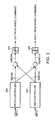
- a typical four-wheeled wheelchaircontacts the ground with all four wheels. If the center of gravity of the combination of the wheelchair and the user remains over the area between the wheels, the wheelchair should not tip over. If the center of gravity is located above and outside of the ground contacting members of the transport device, the transport device may become unstable and tip over.
- the wheelchair 100 and the user 102define a frame.
- the framehas a center of gravity 104 located at a position vertically disposed above the surface 106 .
- the term “surface” as it is used hereinrefers to any surface upon which a human transport device may sit or locomote. Examples of a surface include flat ground, an inclined plane such as a ramp, a gravel covered street, and may include a curb which vertically connects two substantially parallel surfaces vertically displaced from one another (e.g., a street curb).
- the surface 106may be at an incline as compared to the horizontal axis 108 (which is a line in the plane transverse to the local vertical).
- the angle by which the surface 106 is offset from the horizontal axis 108is called the surface pitch and will be represented by an angle denoted as ⁇ s .
- the front wheel 112 and the rear wheel 110 of the wheelchair 100are separated by a distance d.
- the distance d between the two wheelsmay be measured as a linear (e.g., straight line) distance.
- the wheels 110 and 112typically have opposing counterparts (not shown) on the other side of the wheelchair.
- the opposing counterpartsmay each share an axis with wheels 110 and 112 , respectively.
- the area covered by the polygon which connects the points where these four wheels touch the ground (or the outside portions of the ground contacting parts, when the ground contacting part may cover more than a point)provides an area over which the center of gravity 104 may be located while the wheelchair remains stable. This area may be referred to as the footprint of the device.
- the footprint of a deviceis defined by the projection of the area between the wheels as projected onto the horizontal plane. If the center of gravity is above this location, the transport device should remain stable.
- wheelchair 100may tip over. This could happen, for example, when the wheelchair is on a surface that has a steep incline, or, alternatively, if the user ‘pops a wheelie’ in order to surmount a curb, for example.
- the center of gravity 104may shift back and cause the wheelchair 100 to flip over backwards. This is shown in FIG. 1B where the center of gravity 104 is located at a position that is outside the footprint of the wheelchair 100 .
- the center of gravity 104is shown including a gravity acceleration vector (g) which linearly translates the center of gravity 104 in a downward direction.
- the wheelchair 100may rotate about an axis of the rear wheel 110 until the wheelchair 100 contacts the surface being traversed.
- User 102may help to return the center of gravity 104 to a location that is above the area between the wheels 110 and 112 by leaning forward in the wheelchair 100 . Given this limited control of the location of the center of gravity 104 , it is clear that human transport devices such as wheelchairs may encounter great difficulties when traversing uneven surfaces such as a curb or steps.
- ATVall-terrain vehicle
- endoend-over-end
- ATVsmay benefit from stabilization in one or more of the fore-aft or left-right planes, especially under conditions in which fewer than a stable complement of wheels are in contact with the ground.
- Vehicles of this sortmay be more efficiently and safely operated employing control modes supplementary to those described in the prior art.
- a methodfor fore-aft stabilization of a vehicle for motion in a specified direction over an underlying surface, where the vehicle having a plurality of driven wheels including a forward wheel and an aft wheel, and with the forward wheel characterized by a force normal to the instantaneous direction of motion of the vehicle.
- the methodhas the step of applying a torque to the aft wheel based on the force on the forward wheel normal to the direction of motion and/or the instantaneously sensed tilt of the vehicle.
- the methodmay have additional steps of applying a periodic torque to at least one of the wheels for inducing a small pitch modulation, detecting pitch variation of the vehicle in response to the applied periodic torque, and applying a stabilizing torque to the aft wheel on the basis, at least, of any detected pitch variation in response to the applied periodic torque.
- an apparatusfor pitch stabilization of the motion of a vehicle having at least one forward wheel and at least one aft wheel.
- the apparatushas a sensor for sensing a force on the forward wheel normal to an instantaneous direction of motion of the vehicle, a motor actuator for driving the aft wheel, and a controller for applying a torque to the aft wheel on the basis of a control law based at least on the normal force on the forward wheel.
- a stabilized vehiclehas at least one forward wheel and at least one aft wheel. Additionally, the vehicle has a sensor for sensing a force on the forward wheel normal to an instantaneous direction of motion of the vehicle, and/or an instantaneous pitch of the vehicle and/or a function of the instantaneous pitch. The vehicle also has a motor actuator for driving the aft wheel, and a controller for applying a torque to the aft wheel on the basis of a control law based at least on the normal force on the forward wheel.
- the vehiclemay include a pedal-driven bicycle, a motorcycle, or a wheelchair.
- a vehiclewith a plurality of wheels, including at least one forward wheel and at least one aft wheel.
- a motor actuatordrives each aft wheel, and a controller governs the motor actuator or motor actuators in such a manner as to dynamically stabilize the vehicle when the forward wheel is not in contact with the underlying surface.
- a left aft actuatordrives a left aft wheel independently of the right aft wheel, thus the controller can govern differential rotation of the left and right aft wheels for controlling yaw of the vehicle whether a forward wheel is in contact with the ground, or not.
- the controlleris such as to govern the motor actuator according to a control law independent of whether the forward wheel is in contact with the underlying surface.
- the vehiclemay further have a user input device for providing a throttle output signal, and a pitch sensor for providing a pitch signal.
- the controllermay then govern the motor actuator according to a control law based at least upon the throttle output signal or the pitch signal or a pitch rate signal. More particularly, the controller may govern the motor actuator according to a control law based at least upon the pitch signal when the vehicle pitch angle exceeds a specified value.
- a vehiclethat includes a first fore-wheel coupled to a first pivot point by a first strut and a second fore-wheel coupled to the first pivot point by a second strut.
- the vehicle of this embodimentalso includes at least one aft-wheel coupled to the first pivot point.
- the first and second strutsare spaced apart from one another and are arranged and configured to cause the vehicle to vary its direction of motion by causing the first fore-wheel and the second fore-wheel to both pivot about at least their respective vertical or inclined axis.
- a vehiclethat includes a central pivot.
- the vehiclealso includes a first fore-wheel coupled to the central pivot point by a first strut, the first strut being arranged and configured to rotate about the central pivot during operation and a second fore-wheel coupled to the central pivot by a second strut, the second strut being arranged and configured to rotate about the central pivot during operation.
- the vehicle of this embodimentalso includes at least one aft-wheel coupled to the central pivot by a connecting member arranged configured to retain a fixed orientation with respect to the central pivot.
- a vehiclethat includes a plurality of wheels, including at least one forward wheel and at least two aft wheels.
- the vehicle of this embodimentalso includes at least one motor actuator that drives each aft wheel and at least one yaw controller.
- the vehicle of this embodimentalso includes a controller that controls the at least one motor actuator such that a direction imparted on the at least one forward wheel by the yaw controller is replicated by differential rotation of the at least two aft wheels.
- a vehiclethat includes a plurality of wheels, including at least one forward wheel and at least two aft wheels.
- the vehicle of this embodimentalso includes at least one motor actuator that drives each aft wheel and at least one yaw controller.
- the vehicle of this embodimentmay also include a throttle and a controller that, when all of the plurality of wheels is in contact with a surface being traversed, causes the vehicle to accelerate when the throttle is rotated and that, when the at least one forward wheel is not in contact with a surface being traversed, causes an offset from a pitch limit to be adjusted when the throttle is rotated.
- FIGS. 1A and 1Bare schematic side views of a prior art personal vehicle of the type in which an embodiment of the invention may be advantageously employed;
- FIG. 2is a diagram of typical components of a personal vehicle of the type in which an embodiment of the invention may be advantageously employed indicating the variables used in the description of specific embodiments of the present invention
- FIG. 3is a block diagram depicting the coupling of pitch and yaw controller outputs for generation of wheel amplifier commands
- FIG. 4Ais a block diagram showing the constitutive inputs of a pitch command in accordance with an embodiment of the present invention.
- FIG. 4Bis a block diagram showing the constitutive inputs of a pitch command with a unilateral limit in accordance with an embodiment of the present invention
- FIG. 5Ais a block diagram showing the constitutive inputs of a yaw command in accordance with embodiments of the present invention.
- FIGS. 5B and 5Care block diagrams of different embodiments of a yaw controller in accordance with embodiments of the present invention.
- FIG. 6is a side view of an all-terrain vehicle capable of balancing operation in accordance with one embodiment of the present invention.
- FIG. 7is a perspective view from above of the embodiment of the invention of FIG. 6 ;
- FIG. 8is a further side view of the all-terrain vehicle of FIG. 6 showing operation by a standing user;
- FIG. 9is yet a further side view of the all-terrain vehicle of FIG. 6 showing operation by a seated user;
- FIG. 10shows the coupling of the handlebar to the upper pushrods for steering of the front wheels in accordance with a preferred embodiment of the invention.
- FIG. 11shows the coupling of the lower pushrods to steer the forward wheels, in accordance with the embodiment of FIG. 10 .
- a vehiclemay be said to act as “balancing” if it is capable of operation on one or more wheels but would be unable to stand on those wheels alone, but for operation of a control-loop governing operation of the wheels.
- a balancing vehiclewhen operated in a balancing mode, lacks static stability but is dynamically balanced.
- the wheels, or other ground-contacting elements, that provide contact between such a vehicle and the ground or other underlying surface, and minimally support the transporter with respect to tipping during routine operation,are referred to herein as “primary wheels.”
- “Stability” as used in this description and in any appended claimsrefers to the mechanical condition of an operating position with respect to which the system will naturally return if the system is perturbed away from the operating position in any respect.
- the term “system”refers to all mass caused to move due to motion of the wheels with respect to the surface over which the vehicle is moving, and thus includes both the vehicle and the rider.
- leanis often used with respect to a system balanced on a single point of a perfectly rigid member.
- the point (or line) of contact between the member and the underlying surfacehas zero theoretical width.
- leanmay refer to a quantity that expresses the orientation with respect to the vertical (i.e., an imaginary line passing through the center of the earth) of a line from the center of gravity (CG) of the system through the theoretical line of ground contact of the wheel.
- CGcenter of gravity
- FIG. 2One embodiment of a stabilized vehicle in accordance with the present invention is depicted in FIG. 2 and designated generally by numeral 10 .
- User 8as shown in FIG. 2 , is seated position on user support 12 of vehicle 10 , though it is to be understood that user 8 may be supported otherwise than by sitting on a seat, and may, for example, within the scope of the present invention, be standing on a user support in the form of a platform.
- Aft wheels 21are coaxial about an axis defined as the Y axis.
- Each of rear wheels 21is driven by a motor actuator (not shown) disposed within a power base 24 such that steering may be effectuated through differential torque applied to respective rear wheels 21 .
- Compensating, by differential actuation of the rear wheels for the increased rotational travel of the outer wheel on a turnmay be referred to herein as an “active differential.”
- Rider 8may be supported on vehicle 10 in various body positions, thereby controlling the position of the center of mass of the vehicle, as governed by the distribution of weight of the load, namely the user. For example, user 8 may be seated, as shown in FIG. 2 , on seat 12 , with his feet resting on footrest 26 .
- vehicle 10additionally, has two forward wheels 13 (of which one is visible in the side view of FIG. 2 ), typically in contact with the ground during ordinary operation.
- Forward wheel 13 and one or more other forward wheelsmay be mounted on a common axle or otherwise, and pivoting of any of the forward wheels is within the scope of the present invention.
- Personal vehicles designed for enhanced maneuverability and safetymay also include one or more clusters of wheels, with the cluster and the wheels in each cluster capable of being motor-driven independently of each other. Such vehicles are described in U.S. Pat. Nos. 5,701,965, 5,971,091, 6,302,230, 6,311,794, and 6,553,271, all of which patents are incorporated herein by reference.
- Controller 30provides for stability of the vehicle by continuously sensing the orientation of the vehicle and the commanded velocity, as described in detail below, determining the corrective action to maintain stability, and commanding the wheel motors to make any necessary corrective action.
- a user input device 18which may be a joystick, handlebars or by any other user input mechanisms.
- a variety of steering deviceswhich are further examples of user input mechanisms that may be employed within the scope of the present invention are described in U.S. Pat. Nos. 6,581,714 and 6,789,640, which are incorporated herein by reference.
- a sensor unit 28is provided as part of power base 24 for providing one or more sensor signals to controller 30 .
- Sensor unit 28may provide a measure of pitch rate and/or pitch of the vehicle, and may employ inertial sensing of the type described in detail in U.S. Pat. No. 6,332,103, which is incorporated herein by reference.
- sensor unit 28may include a force sensor for measuring the force (designated by arrow 32 ) normal to the underlying surface that is exerted on the underlying surface by wheel 13 (and, reciprocally, on the wheel by the underlying surface).
- Force sensorssuch as those based on piezoresistors, are well-known in the art, and any kind of force sensor is within the scope of the present invention.
- a simplified control algorithm for achieving balance in the embodiment of the invention according to FIG. 2is now described.
- the control algorithmis described for the case of a single driven wheel, as may be employed for stabilization of an in-line bicycle or motorcycle.
- the generalization to the case of multiple driven wheelsis discussed in detail below.
- Eqn. (1)allows for application of a periodic driving component, of period 2 ⁇ / ⁇ and amplitude A (which may be zero, in the case of no applied modulation), to the torque applied to the driven wheel.
- the periodic function f( ⁇ t)may be a sinusoidal function, for example.
- the amplifier controlmay be configured to control motor current (in which case torque T is commanded) or, alternatively, the voltage applied to the motor may be controlled, in which case the commanded parameter is velocity.
- K 3determines the gain of the user input, and may advantageously be a non-linear function, providing, for example, greater sensitivity near zero velocity.
- the K 2 termprovides for control based on the instantaneous pitch rate, ⁇ dot over ( ⁇ ) ⁇ , of the vehicle, as measured by a pitch rate sensor or by differentiation of a measured pitch.
- the response of a normal force 32 measured by sensor 28 in response to the applied pitch modulation Af( ⁇ t),may be used, in accordance with embodiments of the invention, to counteract further backward leaning of the vehicle and maintain contact of the forward wheel with the ground, or, alternatively, impose a limit on rearward tilt.
- separate motorsmay be provided for left and right wheels of the vehicle and the torque desired from the left motor and the torque to be applied by the right motor can be governed in the general manner described above. Additionally, tracking both the left wheel motion and the right wheel motion permits adjustments to be made to prevent unwanted turning of the vehicle and to account for performance variations between the two drive motors.
- differential drive of the two rear wheels tracksturns according to the same yaw input as applied, via mechanical linkages, to the front wheels. This operation is described below, with reference to FIGS. 10 and 11 .
- steering, or yaw control, of the vehiclemay be accomplished by adding a turning command to the wheel amplifiers and have the following form.
- Inputs(described below) corresponding to values of vehicle parameters are used by Pitch Controller 500 and Yaw Controller 502 to derive a balance control signal BalCmd and a yaw control signal YawCmd according to algorithms discussed in the succeeding paragraphs.
- LeftCmdBalCmd+YawCmd (2)
- RightCmdBalCmd ⁇ YawCmd (3)
- the LeftCmd and RightCmdare the command sent by the controllers 500 and 502 to the left and right motor amplifiers, respectively, after differentiation or other conditioning as appropriate.
- the LeftCmd and RightCmd'smay be conditional, respectively, by differentiators 504 and 506 .
- the LeftCmd and RightCmdrepresent voltage if the amplifiers are in voltage control mode, current if the amplifiers are in current control mode, or duty cycle if the amplifiers are in duty cycle control mode.
- BalCmdis the command sent by the Pitch Controller 500 to each amplifier to maintain the transporter in a balanced state while moving or while at rest.
- the YawCmdcauses the transporter to turn by reducing the command to one of the wheels while increasing the command to the other wheel.
- a positive YawCmdincreases the command to the left wheel while decreasing the command to the right wheel thereby causing the transporter to execute a right turn.
- the YawCmdmay be generated by a yaw-input device described above with no feedback loop or in a closed cycle loop to correct yaw position errors as described in U.S. Pat. No. 6,288,505.
- the inputsinclude a desired pitch ⁇ desired , the actual measured pitch ⁇ , the pitch rate ⁇ dot over ( ⁇ ) ⁇ , and the component of the wheel rotation velocity that is common to the two primary wheels, ⁇ com .
- Both ⁇ and ⁇ dot over ( ⁇ ) ⁇may be derived from inertial sensing, as described in U.S. Pat. No. 6,332,103, which is incorporated herein by reference.
- Desired pitch ⁇ desired and current instantaneous pitch ⁇are differenced in summer 520 to produce a pitch error ⁇ err .
- pitch limitingis unilateral, such that a limit is provided on one end of a range of allowed values of pitch. If that pitch is exceeding, a restoring torque moves the vehicle in the direction of the pitch limit.
- the usermay shift her weight backward, thereby ‘popping’ the vehicle into a two-wheeled balancing condition where stability is maintained until she shifts her weight forward to restore operation on all wheels.
- a term quadratic in pitch error ⁇ err(preserving the sign of the actual pitch error) may also be provided, as shown in FIG. 4B , thereby providing more intense response to large deviations in pitch as may result from encountering an obstacle, for example.
- FIG. 5Adepicts the differencing, in summer 522 , of the current yaw value ⁇ with respect to the desired yaw value ⁇ desired to obtain the current yaw error ⁇ err .
- Desired yaw value ⁇ desiredis obtained from a user input such as joystick 18 or other user input device employed for directional input as discussed above.
- the current value of yawis derived from various state estimates, such as the differential wheel velocities, inertial sensing, etc. Derivation of the yaw command from the yaw error is provided by controller 524 according to various processing algorithms.
- FIGS. 5B and 5CTwo examples of yaw control algorithms are shown in FIGS. 5B and 5C .
- FIG. 5Bshows a control law implemented input signal ⁇ err is added, by summer 560 , to the derivative of itself (output of differentiator 562 ) and the intergration of itself (output of integrator 564 ).
- each signalcould have a gain applied to it (for example, by gain blocks 568 , 569 , and 570 ) or other signal processing such as smoother 566 .
- Another possibilityis to simply omit the derivative signal as shown in FIG. 5C .
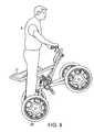
- the present inventionmay also be embodied in a balancing all-terrain vehicle as depicted in FIG. 6 and designated generally by numeral 10 .
- User 8as shown in FIG. 6 , is in a seated position on user support 12 of all-terrain vehicle 10 .
- Aft wheels 21 and 22are shown as coaxial about an axis defined as the Y axis.
- each of rear wheels 21 and 22is driven by a motor actuator 24 such that steering may be effectuated through differential torque applied to of rear wheels 21 and 22 .
- Rider 8may be supported on vehicle 10 in various body positions, thereby controlling the position of the center of mass of the vehicle, as governed by the distribution of weight of the load, namely the user.
- user 8may be seated, as shown in FIG. 6 , on seat 12 , with his feet resting on platform 26 (shown in FIG. 7 ), and may shift his weight relative to the vehicle by positioning himself along the length of seat 12 .
- user 8may stand on platform 26 , with legs athwart seat 12 , as shown in FIG. 8 , or may sit on seat 12 with feet resting on foot rests 28 , as shown in FIG. 9 .
- each forward wheel 13 and 14is mounted on a separate suspension strut 29 such that each forward wheel is suspended independently of one another.
- Controller 30(shown in FIG. 7 ) provides for stability of the vehicle by continuously sensing the orientation of the vehicle and the commanded velocity, as has been described above, determining the corrective action to maintain stability, and commanding the wheel motors to make any necessary corrective action.
- the same control lawmay be applied whether or not forward wheels 13 and 14 of the vehicle 10 are in contact with the ground.
- Steering or other controlmay be provided by the user's rotation of handlebar 18 (shown in FIG. 7 ) about pivot 17 , or by any other user input mechanisms.
- a variety of steering deviceswhich are further examples of user input mechanisms that may be employed within the scope of the present invention are described in U.S. Pat. Nos. 6,581,714 and 6,789,640, which are incorporated herein by reference.
- Handlebar 18may also support user instruments and other user controls such as a throttle, within the scope of the invention.
- a mechanical linkageis provided between the user yaw input and the forward wheels, while the rear wheels are controlled, in synchrony with any turn initiated by the user input, by means of differential rotation of the wheels.
- vehicle steeringis implemented, in accordance with the embodiment shown, by turning handlebar 18 about pivot 17 . This serves two functions: steering the forward wheels, and providing electrical input to cause differential rotation of the aft wheels.
- Bellcrank 80is a lever with two arms forming a fixed angle between them, and a fulcrum at the apex of the angle. This allows rotational motion (of the handlebar pivot) substantially transverse to the ground to be transferred to motion (of the upper push rods) having a significant component parallel to the ground.
- Upper push rods 82in turn, via middle bellcranks 84 , transfer motion to lower pushrods 90 , shown in FIG. 11 , which turn forward wheels 13 and 14 by causing them to pivot about vertical pivot axes 92 . It is to be understood that any other couplings, mechanical or motorized, between the user input and the angle of forward wheels 13 and 14 , may also be employed within the scope of the present invention.
- a signalis generated, by means of a rotational transducer, or otherwise, to serve as the input to yaw controller 502 (shown in FIG. 3 ) to govern differential actuation of the rear wheels.
- yaw controller 502shown in FIG. 3
- the user-intended steeringis accomplished, in accordance with this invention, whether or not the forward wheels are in contact with the ground.
- Various means of converting the mechanical user input (such as handlebar rotation angle) to a yaw signal input to the controller 70are known in the art, such as those described in U.S. Pat. No. 6,581,714, for example, and any such means are encompassed within the scope of the present invention.
Landscapes
- Engineering & Computer Science (AREA)
- Mechanical Engineering (AREA)
- Transportation (AREA)
- Power Engineering (AREA)
- Chemical & Material Sciences (AREA)
- Combustion & Propulsion (AREA)
- Motorcycle And Bicycle Frame (AREA)
- Electric Propulsion And Braking For Vehicles (AREA)
Abstract
Description
T=K1(θ)·(θ−θ0)+K2·{dot over (θ)}+K3·(v−vcommand)+K4·∫(v−vcommand)dt+A·f(ωt), (Eqn. 1)
where:
- T denotes a torque applied to a ground-contacting element about its axis of rotation;
- K1(θ) is a gain function that may depend, as discussed below, on the instantaneous value of lean θ;
- θ is a quantity corresponding to the lean of the entire system about the ground contact region beneath the common axis Y of the rear wheels, with θ0representing the magnitude of a system pitch offset, all as discussed in detail below;
- v identifies the fore-aft velocity along the surface, with vcommandrepresenting the magnitude of a user input such as a throttle constituted by user input (e.g., joystick)18;
- a dot over a character denotes a variable differentiated with respect to time; and
- a subscripted variable denotes a specified offset that may be input into the system as described below; and
- K1, K2, K3and K4are gain functions or coefficients that may be configured, either in design of the system or in real-time, on the basis of a current operating mode and operating conditions as well as preferences of a user. The gain coefficients may be of a positive, negative, or zero magnitude. The gains K1, K2, K3and K4 are dependent upon the physical parameters of the system and other effects such as gravity. The simplified control algorithm of Eqn. 1 maintains balance of the vehicle in the presence of changes to the system's center of mass due to body motion of the rider or features of the underlying terrain.
LeftCmd=BalCmd+YawCmd (2)
RightCmd=BalCmd−YawCmd (3)
The LeftCmd and RightCmd are the command sent by the
Claims (4)
Priority Applications (2)
| Application Number | Priority Date | Filing Date | Title |
|---|---|---|---|
| US11/249,136US7900725B2 (en) | 2002-06-11 | 2005-10-11 | Vehicle control by pitch modulation |
| US12/337,249US7757794B2 (en) | 2002-06-11 | 2008-12-17 | Vehicle control by pitch modulation |
Applications Claiming Priority (7)
| Application Number | Priority Date | Filing Date | Title |
|---|---|---|---|
| US38764102P | 2002-06-11 | 2002-06-11 | |
| US38872302P | 2002-06-14 | 2002-06-14 | |
| US10/459,173US7017686B2 (en) | 2002-06-11 | 2003-06-11 | Hybrid human/electric powered vehicle |
| US10/460,053US6827163B2 (en) | 1994-05-27 | 2003-06-12 | Non-linear control of a balancing vehicle |
| US61724404P | 2004-10-08 | 2004-10-08 | |
| US10/990,715US20050126832A1 (en) | 2002-06-14 | 2004-11-17 | Non-linear control of a balancing vehicle |
| US11/249,136US7900725B2 (en) | 2002-06-11 | 2005-10-11 | Vehicle control by pitch modulation |
Related Parent Applications (2)
| Application Number | Title | Priority Date | Filing Date |
|---|---|---|---|
| US10/459,173Continuation-In-PartUS7017686B2 (en) | 2002-06-11 | 2003-06-11 | Hybrid human/electric powered vehicle |
| US10/990,715Continuation-In-PartUS20050126832A1 (en) | 2002-06-11 | 2004-11-17 | Non-linear control of a balancing vehicle |
Related Child Applications (2)
| Application Number | Title | Priority Date | Filing Date |
|---|---|---|---|
| US10/990,715ContinuationUS20050126832A1 (en) | 2002-06-11 | 2004-11-17 | Non-linear control of a balancing vehicle |
| US12/337,249DivisionUS7757794B2 (en) | 2002-06-11 | 2008-12-17 | Vehicle control by pitch modulation |
Publications (2)
| Publication Number | Publication Date |
|---|---|
| US20060108156A1 US20060108156A1 (en) | 2006-05-25 |
| US7900725B2true US7900725B2 (en) | 2011-03-08 |
Family
ID=46322873
Family Applications (2)
| Application Number | Title | Priority Date | Filing Date |
|---|---|---|---|
| US11/249,136Active2026-02-27US7900725B2 (en) | 2002-06-11 | 2005-10-11 | Vehicle control by pitch modulation |
| US12/337,249Expired - LifetimeUS7757794B2 (en) | 2002-06-11 | 2008-12-17 | Vehicle control by pitch modulation |
Family Applications After (1)
| Application Number | Title | Priority Date | Filing Date |
|---|---|---|---|
| US12/337,249Expired - LifetimeUS7757794B2 (en) | 2002-06-11 | 2008-12-17 | Vehicle control by pitch modulation |
Country Status (1)
| Country | Link |
|---|---|
| US (2) | US7900725B2 (en) |
Cited By (56)
| Publication number | Priority date | Publication date | Assignee | Title |
|---|---|---|---|---|
| US20080223637A1 (en)* | 2006-12-19 | 2008-09-18 | Bradley Wayne Bartilson | Safe, Super-efficient, Four-wheeled Vehicle Employing Large Diameter Wheels with Continuous-Radius Tires, with Leaning Option |
| US20090319124A1 (en)* | 2007-04-27 | 2009-12-24 | Toshio Fuwa | Inverted wheel type moving body and method of controlling the same (as amended) |
| US20100030442A1 (en)* | 2008-07-29 | 2010-02-04 | Yusuke Kosaka | Movable body, travel device, and movable body control method |
| US8403095B1 (en)* | 2011-12-05 | 2013-03-26 | Bryce A. Ecklein | Step on-step off motorized utility vehicle |
| US8694161B2 (en)* | 2010-12-23 | 2014-04-08 | Thales | Collaborative automated mobile platform |
| US20140114559A1 (en)* | 2011-06-28 | 2014-04-24 | Hitachi, Ltd. | Inverted Pendulum Type Moving Body Having Velocity Planning Device |
| US8800697B2 (en) | 2009-09-01 | 2014-08-12 | Ryno Motors, Inc. | Electric-powered self-balancing unicycle with steering linkage between handlebars and wheel forks |
| US9085334B2 (en) | 2012-08-22 | 2015-07-21 | Ryno Motors, Inc. | Electric-powered self-balancing unicycle |
| US9101817B2 (en) | 2013-05-06 | 2015-08-11 | Future Motion, Inc. | Self-stabilizing skateboard |
| USD746928S1 (en) | 2014-10-20 | 2016-01-05 | Future Motion, Inc. | Skateboard |
| US9452345B2 (en) | 2014-11-05 | 2016-09-27 | Future Motion, Inc. | Rider detection system |
| US9598141B1 (en) | 2016-03-07 | 2017-03-21 | Future Motion, Inc. | Thermally enhanced hub motor |
| USD803963S1 (en) | 2016-07-20 | 2017-11-28 | Razor Usa Llc | Two wheeled board |
| USD807457S1 (en) | 2016-07-20 | 2018-01-09 | Razor Usa Llc | Two wheeled board |
| US9908580B2 (en) | 2016-06-02 | 2018-03-06 | Future Motion, Inc. | Vehicle rider detection using strain gauges |
| US9962597B2 (en) | 2016-10-11 | 2018-05-08 | Future Motion, Inc. | Suspension system for one-wheeled vehicle |
| US9999827B2 (en) | 2016-10-25 | 2018-06-19 | Future Motion, Inc. | Self-balancing skateboard with strain-based controls and suspensions |
| USD821517S1 (en) | 2017-01-03 | 2018-06-26 | Future Motion, Inc. | Skateboard |
| US10010784B1 (en) | 2017-12-05 | 2018-07-03 | Future Motion, Inc. | Suspension systems for one-wheeled vehicles |
| US10112680B2 (en) | 2016-03-07 | 2018-10-30 | Future Motion, Inc. | Thermally enhanced hub motor |
| USD837323S1 (en) | 2018-01-03 | 2019-01-01 | Razor Usa Llc | Two wheeled board |
| USD840872S1 (en) | 2016-07-20 | 2019-02-19 | Razor Usa Llc | Two wheeled board |
| US10220843B2 (en) | 2016-02-23 | 2019-03-05 | Deka Products Limited Partnership | Mobility device control system |
| USD843532S1 (en) | 2018-02-23 | 2019-03-19 | Future Motion, Inc. | Skateboard |
| USD846452S1 (en) | 2017-05-20 | 2019-04-23 | Deka Products Limited Partnership | Display housing |
| USD850552S1 (en) | 2018-02-23 | 2019-06-04 | Future Motion, Inc. | Skateboard |
| US10399457B2 (en) | 2017-12-07 | 2019-09-03 | Future Motion, Inc. | Dismount controls for one-wheeled vehicle |
| US10456658B1 (en) | 2019-02-11 | 2019-10-29 | Future Motion, Inc. | Self-stabilizing skateboard |
| USD881308S1 (en) | 2019-03-11 | 2020-04-14 | Future Motion, Inc. | Fender for electric vehicle |
| USD881307S1 (en) | 2019-03-11 | 2020-04-14 | Future Motion, Inc. | Fender for electric vehicle |
| USD886929S1 (en) | 2019-03-11 | 2020-06-09 | Future Motion, Inc. | Rear bumper for electric vehicle |
| USD888175S1 (en) | 2019-03-11 | 2020-06-23 | Future Motion, Inc. | Electric vehicle front |
| US10695656B2 (en) | 2017-12-01 | 2020-06-30 | Future Motion, Inc. | Control system for electric vehicles |
| USD889577S1 (en) | 2019-03-11 | 2020-07-07 | Future Motion, Inc. | Rotatable handle for electric vehicle |
| USD890279S1 (en) | 2019-03-11 | 2020-07-14 | Future Motion, Inc. | Electric vehicle with fender |
| USD890280S1 (en) | 2019-03-11 | 2020-07-14 | Future Motion, Inc. | Rider detection sensor for electric vehicle |
| USD890278S1 (en) | 2019-03-11 | 2020-07-14 | Future Motion, Inc. | Electric vehicle |
| US10772774B2 (en) | 2016-08-10 | 2020-09-15 | Max Mobility, Llc | Self-balancing wheelchair |
| USD897469S1 (en) | 2019-03-11 | 2020-09-29 | Future Motion, Inc. | Foot pad for electric vehicle |
| US10802495B2 (en) | 2016-04-14 | 2020-10-13 | Deka Products Limited Partnership | User control device for a transporter |
| US10908045B2 (en) | 2016-02-23 | 2021-02-02 | Deka Products Limited Partnership | Mobility device |
| US10926756B2 (en) | 2016-02-23 | 2021-02-23 | Deka Products Limited Partnership | Mobility device |
| USD915248S1 (en) | 2017-05-20 | 2021-04-06 | Deka Products Limited Partnership | Set of toggles |
| USD941948S1 (en) | 2016-07-20 | 2022-01-25 | Razor Usa Llc | Two wheeled board |
| US11273364B1 (en) | 2021-06-30 | 2022-03-15 | Future Motion, Inc. | Self-stabilizing skateboard |
| US11299059B1 (en) | 2021-10-20 | 2022-04-12 | Future Motion, Inc. | Self-stabilizing skateboard |
| US11399995B2 (en) | 2016-02-23 | 2022-08-02 | Deka Products Limited Partnership | Mobility device |
| US11479311B2 (en) | 2019-01-07 | 2022-10-25 | Future Motion, Inc. | Self-balancing systems for electric vehicles |
| US11654995B2 (en) | 2017-12-22 | 2023-05-23 | Razor Usa Llc | Electric balance vehicles |
| US11681293B2 (en) | 2018-06-07 | 2023-06-20 | Deka Products Limited Partnership | System and method for distributed utility service execution |
| US11890528B1 (en) | 2022-11-17 | 2024-02-06 | Future Motion, Inc. | Concave side rails for one-wheeled vehicles |
| US12005340B2 (en) | 2020-10-06 | 2024-06-11 | Future Motion, Inc. | Suspension systems for an electric skateboard |
| USD1047785S1 (en) | 2017-05-20 | 2024-10-22 | Deka Products Limited Partnership | Toggle control device |
| US12187373B1 (en) | 2024-02-29 | 2025-01-07 | Future Motion, Inc. | Skateboard footpads having foot engagement structures and traction inserts |
| US12227257B2 (en) | 2017-04-01 | 2025-02-18 | Razor Usa Llc | Electric balance vehicles |
| US12440401B2 (en) | 2024-05-22 | 2025-10-14 | Deka Products Limited Partnership | Mobility device |
Families Citing this family (33)
| Publication number | Priority date | Publication date | Assignee | Title |
|---|---|---|---|---|
| US7740099B2 (en) | 1999-06-04 | 2010-06-22 | Segway Inc. | Enhanced control of a transporter |
| US7726446B1 (en)* | 2005-01-28 | 2010-06-01 | Vernon Roger Buchanan | Mobile hunting blind |
| US7979179B2 (en) | 2006-08-11 | 2011-07-12 | Segway Inc. | Apparatus and method for pitch state estimation for a vehicle |
| CN101501598A (en) | 2006-08-11 | 2009-08-05 | 塞格威股份有限公司 | Speed limitation of electric vehicles |
| US7798264B2 (en)* | 2006-11-02 | 2010-09-21 | Hutcheson Timothy L | Reconfigurable balancing robot and method for dynamically transitioning between statically stable mode and dynamically balanced mode |
| US8900086B2 (en)* | 2007-08-02 | 2014-12-02 | Honda Motor Co., Ltd. | Hydraulic vehicle clutch system, drivetrain for a vehicle including same, and method |
| TW200934684A (en)* | 2007-10-19 | 2009-08-16 | Segway Inc | Apparatus and method for controlling vehicle motion |
| US8146696B2 (en)* | 2008-09-02 | 2012-04-03 | Segway, Inc. | Methods and apparatus for moving a vehicle up or down a sloped surface |
| US20100207564A1 (en) | 2009-02-18 | 2010-08-19 | Segway Inc. | Power Source Estimation Methods and Apparatus |
| US8449430B2 (en)* | 2010-02-05 | 2013-05-28 | Honda Motor Co., Ltd. | Transversely mounted transaxle having a low range gear assembly and powertrain for a vehicle including same |
| US8527160B2 (en)* | 2010-02-05 | 2013-09-03 | Honda Motor Co., Ltd. | Control system and method for automatic selection of a low range gear ratio for a vehicle drivetrain |
| US20110204592A1 (en)* | 2010-02-17 | 2011-08-25 | Johansen N Layne | Mobility and Accessibility Device and Lift |
| US8452504B2 (en) | 2010-07-30 | 2013-05-28 | Honda Motor Co., Ltd. | Control system and method for automatic control of selection of on-demand all-wheel drive assembly for a vehicle drivetrain |
| US8364369B2 (en) | 2010-07-30 | 2013-01-29 | Honda Motor Co., Ltd. | Low range drive ratio transfer changeover anti-rollback system and method |
| US8534409B2 (en) | 2010-07-30 | 2013-09-17 | Honda Motor Co., Ltd. | Drivetrain for a vehicle and method of controlling same |
| US9205869B2 (en) | 2010-08-16 | 2015-12-08 | Honda Motor Co., Ltd. | System and method for determining a steering angle for a vehicle and system and method for controlling a vehicle based on same |
| KR101034814B1 (en)* | 2010-12-22 | 2011-05-16 | 오봉석 | Electric four-wheeled motorcycle |
| NZ593139A (en)* | 2011-05-30 | 2014-04-30 | Spoke House Ltd | Exercise device |
| EP2543552B1 (en)* | 2011-07-04 | 2020-05-06 | Veoneer Sweden AB | A vehicle safety system |
| US9616318B2 (en) | 2013-03-15 | 2017-04-11 | Stealth Electric Longboards | Powered personal transportation systems and methods |
| US9073585B2 (en)* | 2013-12-06 | 2015-07-07 | Blair Douglas Jackson | Light weight electric vehicle |
| US9475193B2 (en)* | 2015-02-09 | 2016-10-25 | Harris Corporation | Unmanned ground vehicle stability control |
| CN105292301A (en)* | 2015-11-06 | 2016-02-03 | 祁刚 | Foldable, combined and multi-functional automobile |
| JP6380485B2 (en)* | 2016-08-12 | 2018-08-29 | トヨタ自動車株式会社 | Traveling device |
| JP6575470B2 (en)* | 2016-09-07 | 2019-09-18 | トヨタ自動車株式会社 | Traveling device |
| JP6497368B2 (en)* | 2016-09-13 | 2019-04-10 | トヨタ自動車株式会社 | Traveling device |
| CN106995027B (en)* | 2017-05-11 | 2022-11-08 | 常州爱尔威智能科技有限公司 | Intelligent electric vehicle |
| JP6949642B2 (en)* | 2017-09-28 | 2021-10-13 | 株式会社クボタ | Mobile |
| US11027786B2 (en) | 2018-11-20 | 2021-06-08 | Harley-Davidson Motor Company Group, LLC | Gyroscopic rider assist device |
| US11591041B2 (en)* | 2019-01-07 | 2023-02-28 | Joel Weiss | Self-balancing, electronically-assisted, rideable devices |
| US11305816B2 (en)* | 2019-04-15 | 2022-04-19 | Honda Motor Co., Ltd. | Deployable quad vehicle |
| CA3096926A1 (en)* | 2019-10-22 | 2021-04-22 | LyteHorse Labs, Inc. | System and method for a standup motorized transport utility vehicle |
| CN111123972B (en)* | 2019-12-04 | 2023-04-14 | 北京航天时代激光导航技术有限责任公司 | Inertial measurement combined rotation modulation method based on course angle tracking |
Citations (125)
| Publication number | Priority date | Publication date | Assignee | Title |
|---|---|---|---|---|
| US584127A (en) | 1897-06-08 | Edmond draullette and ernest catois | ||
| US849270A (en) | 1906-05-15 | 1907-04-02 | Andrew Schafer | Truck. |
| GB152664A (en) | 1919-05-08 | 1922-01-19 | Giuseppe Garanzini | Improved wheels for vehicles intended to move over soft ground |
| FR980237A (en) | 1949-02-07 | 1951-05-09 | Baby carriage or crawler stroller | |
| US2742973A (en) | 1952-02-01 | 1956-04-24 | Johannesen Hans Arne Ingolf | Powered invalid chair and handle control therefor |
| US3145797A (en) | 1960-09-21 | 1964-08-25 | Charles F Taylor | Vehicle |
| US3260324A (en) | 1963-11-12 | 1966-07-12 | Caesar R Suarez | Motorized unicycle |
| US3288234A (en) | 1964-08-17 | 1966-11-29 | Jack M Feliz | Stair climbing conveyance |
| US3348518A (en) | 1965-10-13 | 1967-10-24 | Lockheed Aircraft Corp | Amphibious star-wheeled vehicle |
| US3374845A (en) | 1966-05-05 | 1968-03-26 | Selwyn Donald | Command control system for vehicles |
| US3399742A (en) | 1966-06-23 | 1968-09-03 | Franklin S. Malick | Powered unicycle |
| US3446304A (en) | 1966-08-08 | 1969-05-27 | Constantin Alimanestiand | Portable conveyor |
| US3450219A (en) | 1967-03-13 | 1969-06-17 | John F Fleming | Stair-climbing vehicle |
| US3515401A (en) | 1968-11-06 | 1970-06-02 | Eshcol S Gross | Stair climbing dolly |
| GB1213930A (en) | 1969-05-29 | 1970-11-25 | John Fay Fleming | A vehicle for climbing stairs |
| US3580344A (en) | 1968-12-24 | 1971-05-25 | Johnnie E Floyd | Stair-negotiating wheel chair or an irregular-terrain-negotiating vehicle |
| US3596298A (en) | 1969-05-14 | 1971-08-03 | John A Durst Jr | Lifting device |
| US3860264A (en) | 1973-01-15 | 1975-01-14 | Mattel Inc | Lean velocipede |
| US3872945A (en) | 1974-02-11 | 1975-03-25 | Falcon Research And Dev Co | Motorized walker |
| US3952822A (en) | 1973-03-19 | 1976-04-27 | Stiftelsen Teknisk Hjalp At Handikappade Permobilstiftelsen | Electrically powered wheel-chair for indoor and outdoor use |
| US4018440A (en) | 1975-03-31 | 1977-04-19 | Deutsch Fritz A | Invalid walker with wheel control mechanism |
| US4062558A (en) | 1976-07-19 | 1977-12-13 | David Wasserman | Unicycle |
| US4076270A (en) | 1976-01-19 | 1978-02-28 | General Motors Corporation | Foldable cambering vehicle |
| US4088199A (en) | 1976-02-23 | 1978-05-09 | Wolfgang Trautwein | Stabilized three-wheeled vehicle |
| US4094372A (en) | 1977-02-28 | 1978-06-13 | Notter Michael A | Motorized skateboard with uni-directional rear mounting |
| US4109741A (en) | 1977-07-29 | 1978-08-29 | Gabriel Charles L | Motorized unicycle wheel |
| US4111445A (en) | 1977-06-09 | 1978-09-05 | Kenneth Haibeck | Device for supporting a paraplegic in an upright position |
| US4151892A (en) | 1976-04-28 | 1979-05-01 | Frank Francken | Motorized terrestrial surf-board |
| US4222449A (en) | 1978-06-08 | 1980-09-16 | Feliz Jack M | Step-climbing wheel chair |
| US4264082A (en) | 1979-03-26 | 1981-04-28 | Fouchey Jr Charles J | Stair climbing cart |
| US4266627A (en) | 1978-02-22 | 1981-05-12 | Willy Habegger | Traveling assembly and wheel suspension for a rolling and stepping vehicle |
| US4293052A (en) | 1978-07-17 | 1981-10-06 | Daswick Alexander C | Lightweight two-wheeled vehicle |
| US4325565A (en) | 1980-03-03 | 1982-04-20 | General Motors Corporation | Cambering vehicle |
| FR2502090A1 (en) | 1981-03-17 | 1982-09-24 | Tobex Motivated Chair Cy Ltd | VEHICLE FOR GOING UP AND DOWN FROM STAIRS |
| US4354569A (en) | 1979-04-14 | 1982-10-19 | Heinz Eichholz | Electric vehicle |
| US4363493A (en) | 1980-08-29 | 1982-12-14 | Veneklasen Paul S | Uni-wheel skate |
| DE3128112A1 (en) | 1981-07-16 | 1983-02-03 | Gerhard Dipl.-Ing. 6100 Darmstadt Heid | Small electric vehicle |
| US4373600A (en) | 1980-07-18 | 1983-02-15 | Veda, Inc. | Three wheel drive vehicle |
| US4375840A (en) | 1981-09-23 | 1983-03-08 | Campbell Jack L | Mobile support |
| DE3242880A1 (en) | 1981-11-20 | 1983-06-23 | T.G.R. S.R.L., Ozzano Dell' Emilia | Cart with electrical drive, particularly suitable for transporting heavy and bulky objects on steps |
| DE2048593C2 (en) | 1969-10-04 | 1984-09-06 | Deres Development Corp., Greenwich, Conn. | Mechanical support device, in particular for supporting the human body |
| DE3411489A1 (en) | 1983-03-29 | 1984-10-04 | Aisin Seiki K.K., Kariya, Aichi | DEVICE FOR OPERATING A MEDICAL DEVICE |
| GB2139576A (en) | 1983-05-13 | 1984-11-14 | Mavispace Ltd | Stair climbing devices |
| US4510956A (en) | 1983-08-15 | 1985-04-16 | Lorraine King | Walking aid, particularly for handicapped persons |
| US4560022A (en) | 1983-07-22 | 1985-12-24 | Kassai Kabushikikaisha | Electrically driven children's vehicle |
| US4566707A (en) | 1981-11-05 | 1986-01-28 | Nitzberg Leonard R | Wheel chair |
| US4570078A (en) | 1982-05-27 | 1986-02-11 | Honda Giken Kogyo Kabushiki Kaisha | Switch assembly for a motor vehicle |
| US4571844A (en) | 1982-06-09 | 1986-02-25 | Jeco Co., Ltd. | Angle change detector |
| US4624469A (en) | 1985-12-19 | 1986-11-25 | Bourne Jr Maurice W | Three-wheeled vehicle with controlled wheel and body lean |
| US4657272A (en) | 1985-09-11 | 1987-04-14 | Davenport James M | Wheeled vehicle |
| EP0109927B1 (en) | 1982-10-19 | 1987-06-03 | von Rohr, Martin | Wheel assembly |
| US4685693A (en) | 1986-09-16 | 1987-08-11 | Vadjunec Carl F | Upright wheelchair |
| US4709772A (en) | 1985-01-31 | 1987-12-01 | Pierre Brunet | Motorized moving device |
| US4716980A (en) | 1986-02-14 | 1988-01-05 | The Prime Mover Company | Control system for rider vehicles |
| US4740001A (en) | 1981-09-14 | 1988-04-26 | Torleumke Keith R | Sprag wheel |
| US4746132A (en) | 1987-02-06 | 1988-05-24 | Eagan Robert W | Multi-wheeled cycle |
| US4770410A (en) | 1986-07-03 | 1988-09-13 | Brown Guies L | Walker |
| US4786069A (en) | 1986-06-30 | 1988-11-22 | Tang Chun Yi | Unicycle |
| US4790400A (en) | 1986-07-24 | 1988-12-13 | Eric Sheeter | Stepping vehicle |
| US4790548A (en) | 1987-05-04 | 1988-12-13 | Fabien Decelles | Climbing and descending vehicle |
| US4794999A (en) | 1985-06-25 | 1989-01-03 | Robert Hester | Wheelchair and method of operating same |
| US4798255A (en) | 1987-10-29 | 1989-01-17 | Wu Donald P H | Four-wheeled T-handlebar invalid carriage |
| US4802542A (en) | 1986-08-25 | 1989-02-07 | Falcon Rehabilitation Products, Inc. | Powered walker |
| US4809804A (en) | 1986-08-25 | 1989-03-07 | Falcon Rehabilitation Products, Inc. | Combination wheelchair and walker apparatus |
| US4834200A (en) | 1986-12-15 | 1989-05-30 | Agency Of Industrial Science & Technology | Method and apparatus for dynamic walking control of robot |
| US4863182A (en) | 1988-07-21 | 1989-09-05 | Chern Jiuun F | Skate bike |
| US4867188A (en) | 1986-01-28 | 1989-09-19 | Michael Reid | Orthopaedic trolley |
| US4869279A (en) | 1986-12-22 | 1989-09-26 | Hedges Harry S | Walker |
| US4874055A (en) | 1987-12-16 | 1989-10-17 | Beer Robin F C | Chariot type golf cart |
| US4890853A (en) | 1988-03-07 | 1990-01-02 | Luanne Olson | Wheelchair walker |
| US4919225A (en) | 1988-03-31 | 1990-04-24 | Sturges Daniel D | Platform oriented transportation vehicle |
| US4953851A (en) | 1988-11-07 | 1990-09-04 | Sherlock Lila A | Safety mobilizer walker |
| US4984754A (en) | 1986-07-28 | 1991-01-15 | Arthur Yarrington | Heli-hover amphibious surface effect vehicle |
| US4985947A (en) | 1990-05-14 | 1991-01-22 | Ethridge Kenneth L | Patient assist device |
| US4998596A (en) | 1989-05-03 | 1991-03-12 | Ufi, Inc. | Self-propelled balancing three-wheeled vehicle |
| US5002295A (en) | 1990-04-19 | 1991-03-26 | Pro-China Sporting Goods Industries Inc. | Unicycle having an eccentric wheel |
| US5011171A (en) | 1990-04-20 | 1991-04-30 | Cook Walter R | Self-propelled vehicle |
| US5052237A (en) | 1989-05-17 | 1991-10-01 | Aluweld S.A. | Transmission device |
| US5111899A (en) | 1989-05-17 | 1992-05-12 | Aluweld S.A. | Motorized rolling-chair |
| US5158493A (en) | 1991-05-30 | 1992-10-27 | Richard Morgrey | Remote controlled, multi-legged, walking robot |
| US5168947A (en) | 1991-04-09 | 1992-12-08 | Rodenborn Eugene P | Motorized walker |
| US5171173A (en) | 1990-07-24 | 1992-12-15 | Zebco Corporation | Trolling motor steering and speed control |
| US5186270A (en) | 1991-10-24 | 1993-02-16 | Massachusetts Institute Of Technology | Omnidirectional vehicle |
| EP0537698A1 (en) | 1991-10-18 | 1993-04-21 | T.G.R. S.r.l. | Tracked motor-vehicle, particularly adapted for invalid carriages |
| US5221883A (en) | 1990-11-30 | 1993-06-22 | Honda Giken Kogyo Kabushiki Kaisha | System for controlling locomotion of legged walking robot |
| US5241875A (en) | 1990-09-24 | 1993-09-07 | Uwe Kochanneck | Multiblock-robot |
| US5248007A (en) | 1989-11-21 | 1993-09-28 | Quest Technologies, Inc. | Electronic control system for stair climbing vehicle |
| US5314034A (en) | 1991-11-14 | 1994-05-24 | Chittal Nandan R | Powered monocycle |
| US5350033A (en) | 1993-04-26 | 1994-09-27 | Kraft Brett W | Robotic inspection vehicle |
| US5366036A (en) | 1993-01-21 | 1994-11-22 | Perry Dale E | Power stand-up and reclining wheelchair |
| US5376868A (en) | 1991-04-01 | 1994-12-27 | Aisin Aw Co., Ltd. | Driving force controller for electric motor vehicle |
| US5419624A (en) | 1990-11-24 | 1995-05-30 | Mannesmann Aktiengesellschaft | Arrangement for detecting a critical driving torque in a motor vehicle |
| DE4404594A1 (en) | 1994-02-12 | 1995-08-17 | Dieter Wittelsberger | Vehicle combined steering, acceleration and braking control unit |
| DE19625498C1 (en) | 1996-06-26 | 1997-11-20 | Daimler Benz Ag | Steering device for controlling longitudinal and cross movement of road vehicle |
| US5701965A (en) | 1993-02-24 | 1997-12-30 | Deka Products Limited Partnership | Human transporter |
| US5701968A (en) | 1995-04-03 | 1997-12-30 | Licile Salter Packard Children's Hospital At Stanford | Transitional power mobility aid for physically challenged children |
| US5775452A (en) | 1996-01-31 | 1998-07-07 | Patmont Motor Werks | Electric scooter |
| DE29808091U1 (en) | 1998-05-06 | 1998-08-27 | Brecht, Thomas, 76646 Bruchsal | Screw-on profile part rail brackets |
| DE29808096U1 (en) | 1998-05-06 | 1998-08-27 | Brecht, Thomas, 76646 Bruchsal | Electric motor powered wheelchair suitable for stairs |
| US5973463A (en) | 1996-09-10 | 1999-10-26 | Toyota Jidosha Kabushiki Kaisha | Driving controller for electric vehicle |
| US5971091A (en) | 1993-02-24 | 1999-10-26 | Deka Products Limited Partnership | Transportation vehicles and methods |
| US5975225A (en) | 1993-02-24 | 1999-11-02 | Deka Products Limited Partnership | Transportation vehicles with stability enhancement using CG modification |
| US5986221A (en) | 1996-12-19 | 1999-11-16 | Automotive Systems Laboratory, Inc. | Membrane seat weight sensor |
| US6003624A (en) | 1995-06-06 | 1999-12-21 | University Of Washington | Stabilizing wheeled passenger carrier capable of traversing stairs |
| US6050357A (en) | 1995-05-31 | 2000-04-18 | Empower Corporation | Powered skateboard |
| US6059062A (en) | 1995-05-31 | 2000-05-09 | Empower Corporation | Powered roller skates |
| US6125957A (en) | 1998-02-10 | 2000-10-03 | Kauffmann; Ricardo M. | Prosthetic apparatus for supporting a user in sitting or standing positions |
| US6131057A (en) | 1993-09-17 | 2000-10-10 | Matsushita Electric Industrial Co., Ltd. | Protecting device of electromobile |
| US6223104B1 (en) | 1998-10-21 | 2001-04-24 | Deka Products Limited Partnership | Fault tolerant architecture for a personal vehicle |
| US6225977B1 (en) | 1997-03-25 | 2001-05-01 | John Li | Human balance driven joystick |
| US6288505B1 (en) | 2000-10-13 | 2001-09-11 | Deka Products Limited Partnership | Motor amplifier and control for a personal transporter |
| US6302230B1 (en) | 1999-06-04 | 2001-10-16 | Deka Products Limited Partnership | Personal mobility vehicles and methods |
| US6311794B1 (en) | 1994-05-27 | 2001-11-06 | Deka Products Limited Partneship | System and method for stair climbing in a cluster-wheel vehicle |
| US6332103B1 (en) | 1999-06-30 | 2001-12-18 | Deka Products Limited Partnership | Apparatus and method for a pitch state estimator for a personal vehicle |
| US20020121394A1 (en) | 1999-03-15 | 2002-09-05 | Kamen Dean L. | Control system and method |
| US20030014167A1 (en) | 2000-03-01 | 2003-01-16 | Soren Pedersen | Device for attenuating the pitching of an engine-driven vehicle |
| US6538411B1 (en) | 2000-10-13 | 2003-03-25 | Deka Products Limited Partnership | Deceleration control of a personal transporter |
| US6553271B1 (en) | 1999-05-28 | 2003-04-22 | Deka Products Limited Partnership | System and method for control scheduling |
| US6581714B1 (en) | 1993-02-24 | 2003-06-24 | Deka Products Limited Partnership | Steering control of a personal transporter |
| US20030226698A1 (en) | 2002-06-11 | 2003-12-11 | Kamen Dean L. | Hybrid human/electric powered vehicle |
| US20040064246A1 (en)* | 2000-09-25 | 2004-04-01 | Jianbo Lu | Wheel lift identification for an automotive vehicle using passive and active detection |
| US6789640B1 (en) | 2000-10-13 | 2004-09-14 | Deka Products Limited Partnership | Yaw control for a personal transporter |
| GB2388579B (en) | 2002-05-02 | 2005-10-26 | Ford Global Tech Llc | Vehicle differential control |
| EP0958978B1 (en) | 1998-05-18 | 2007-03-14 | General Motors Corporation | Vehicle yaw control method |
| JP4201793B2 (en) | 2005-11-30 | 2008-12-24 | 大王製紙株式会社 | Cutter equipment |
Family Cites Families (11)
| Publication number | Priority date | Publication date | Assignee | Title |
|---|---|---|---|---|
| US470410A (en)* | 1892-03-08 | pangle | ||
| US399742A (en)* | 1889-03-19 | Bee-hive | ||
| US456022A (en)* | 1891-07-14 | Wire fence | ||
| US395822A (en)* | 1889-01-08 | Steam-engine | ||
| US3348158A (en)* | 1964-11-18 | 1967-10-17 | Avco Corp | Temperature-compensated discriminator providing amplification |
| US3860364A (en)* | 1971-07-09 | 1975-01-14 | Compump System Inc | Pump-compressor system |
| DE8809903U1 (en)* | 1988-08-03 | 1988-09-15 | SKF GmbH, 8720 Schweinfurt | Axial rolling bearings |
| US5602142A (en)* | 1994-12-21 | 1997-02-11 | Evanston Hospital Corporation | DNA-affinic hypoxia selective cytotoxins |
| AU1299097A (en)* | 1996-01-25 | 1997-08-20 | Universite Laval | Marker at the estrogen receptor gene for determination of osteoporosis predisposition |
| US6293052B1 (en)* | 1999-02-24 | 2001-09-25 | Bailey Varnado, Jr. | Multifunctional complex |
| US7210544B2 (en) | 2002-07-12 | 2007-05-01 | Deka Products Limited Partnership | Control of a transporter based on attitude |
- 2005
- 2005-10-11USUS11/249,136patent/US7900725B2/enactiveActive
- 2008
- 2008-12-17USUS12/337,249patent/US7757794B2/ennot_activeExpired - Lifetime
Patent Citations (131)
| Publication number | Priority date | Publication date | Assignee | Title |
|---|---|---|---|---|
| US584127A (en) | 1897-06-08 | Edmond draullette and ernest catois | ||
| US849270A (en) | 1906-05-15 | 1907-04-02 | Andrew Schafer | Truck. |
| GB152664A (en) | 1919-05-08 | 1922-01-19 | Giuseppe Garanzini | Improved wheels for vehicles intended to move over soft ground |
| FR980237A (en) | 1949-02-07 | 1951-05-09 | Baby carriage or crawler stroller | |
| US2742973A (en) | 1952-02-01 | 1956-04-24 | Johannesen Hans Arne Ingolf | Powered invalid chair and handle control therefor |
| US3145797A (en) | 1960-09-21 | 1964-08-25 | Charles F Taylor | Vehicle |
| US3260324A (en) | 1963-11-12 | 1966-07-12 | Caesar R Suarez | Motorized unicycle |
| US3288234A (en) | 1964-08-17 | 1966-11-29 | Jack M Feliz | Stair climbing conveyance |
| US3348518A (en) | 1965-10-13 | 1967-10-24 | Lockheed Aircraft Corp | Amphibious star-wheeled vehicle |
| US3374845A (en) | 1966-05-05 | 1968-03-26 | Selwyn Donald | Command control system for vehicles |
| US3399742A (en) | 1966-06-23 | 1968-09-03 | Franklin S. Malick | Powered unicycle |
| US3446304A (en) | 1966-08-08 | 1969-05-27 | Constantin Alimanestiand | Portable conveyor |
| US3450219A (en) | 1967-03-13 | 1969-06-17 | John F Fleming | Stair-climbing vehicle |
| US3515401A (en) | 1968-11-06 | 1970-06-02 | Eshcol S Gross | Stair climbing dolly |
| US3580344A (en) | 1968-12-24 | 1971-05-25 | Johnnie E Floyd | Stair-negotiating wheel chair or an irregular-terrain-negotiating vehicle |
| US3596298A (en) | 1969-05-14 | 1971-08-03 | John A Durst Jr | Lifting device |
| GB1213930A (en) | 1969-05-29 | 1970-11-25 | John Fay Fleming | A vehicle for climbing stairs |
| DE2048593C2 (en) | 1969-10-04 | 1984-09-06 | Deres Development Corp., Greenwich, Conn. | Mechanical support device, in particular for supporting the human body |
| US3860264A (en) | 1973-01-15 | 1975-01-14 | Mattel Inc | Lean velocipede |
| US3952822A (en) | 1973-03-19 | 1976-04-27 | Stiftelsen Teknisk Hjalp At Handikappade Permobilstiftelsen | Electrically powered wheel-chair for indoor and outdoor use |
| US3872945A (en) | 1974-02-11 | 1975-03-25 | Falcon Research And Dev Co | Motorized walker |
| US4018440A (en) | 1975-03-31 | 1977-04-19 | Deutsch Fritz A | Invalid walker with wheel control mechanism |
| US4076270A (en) | 1976-01-19 | 1978-02-28 | General Motors Corporation | Foldable cambering vehicle |
| US4088199A (en) | 1976-02-23 | 1978-05-09 | Wolfgang Trautwein | Stabilized three-wheeled vehicle |
| US4151892A (en) | 1976-04-28 | 1979-05-01 | Frank Francken | Motorized terrestrial surf-board |
| US4062558A (en) | 1976-07-19 | 1977-12-13 | David Wasserman | Unicycle |
| US4094372A (en) | 1977-02-28 | 1978-06-13 | Notter Michael A | Motorized skateboard with uni-directional rear mounting |
| US4111445A (en) | 1977-06-09 | 1978-09-05 | Kenneth Haibeck | Device for supporting a paraplegic in an upright position |
| US4109741A (en) | 1977-07-29 | 1978-08-29 | Gabriel Charles L | Motorized unicycle wheel |
| US4266627A (en) | 1978-02-22 | 1981-05-12 | Willy Habegger | Traveling assembly and wheel suspension for a rolling and stepping vehicle |
| US4222449A (en) | 1978-06-08 | 1980-09-16 | Feliz Jack M | Step-climbing wheel chair |
| US4293052A (en) | 1978-07-17 | 1981-10-06 | Daswick Alexander C | Lightweight two-wheeled vehicle |
| US4264082A (en) | 1979-03-26 | 1981-04-28 | Fouchey Jr Charles J | Stair climbing cart |
| US4354569A (en) | 1979-04-14 | 1982-10-19 | Heinz Eichholz | Electric vehicle |
| US4325565A (en) | 1980-03-03 | 1982-04-20 | General Motors Corporation | Cambering vehicle |
| US4373600A (en) | 1980-07-18 | 1983-02-15 | Veda, Inc. | Three wheel drive vehicle |
| US4363493A (en) | 1980-08-29 | 1982-12-14 | Veneklasen Paul S | Uni-wheel skate |
| FR2502090A1 (en) | 1981-03-17 | 1982-09-24 | Tobex Motivated Chair Cy Ltd | VEHICLE FOR GOING UP AND DOWN FROM STAIRS |
| DE3128112A1 (en) | 1981-07-16 | 1983-02-03 | Gerhard Dipl.-Ing. 6100 Darmstadt Heid | Small electric vehicle |
| US4740001A (en) | 1981-09-14 | 1988-04-26 | Torleumke Keith R | Sprag wheel |
| US4375840A (en) | 1981-09-23 | 1983-03-08 | Campbell Jack L | Mobile support |
| US4566707A (en) | 1981-11-05 | 1986-01-28 | Nitzberg Leonard R | Wheel chair |
| DE3242880A1 (en) | 1981-11-20 | 1983-06-23 | T.G.R. S.R.L., Ozzano Dell' Emilia | Cart with electrical drive, particularly suitable for transporting heavy and bulky objects on steps |
| US4570078A (en) | 1982-05-27 | 1986-02-11 | Honda Giken Kogyo Kabushiki Kaisha | Switch assembly for a motor vehicle |
| US4571844A (en) | 1982-06-09 | 1986-02-25 | Jeco Co., Ltd. | Angle change detector |
| EP0109927B1 (en) | 1982-10-19 | 1987-06-03 | von Rohr, Martin | Wheel assembly |
| DE3411489A1 (en) | 1983-03-29 | 1984-10-04 | Aisin Seiki K.K., Kariya, Aichi | DEVICE FOR OPERATING A MEDICAL DEVICE |
| GB2139576A (en) | 1983-05-13 | 1984-11-14 | Mavispace Ltd | Stair climbing devices |
| US4560022A (en) | 1983-07-22 | 1985-12-24 | Kassai Kabushikikaisha | Electrically driven children's vehicle |
| US4510956A (en) | 1983-08-15 | 1985-04-16 | Lorraine King | Walking aid, particularly for handicapped persons |
| US4709772A (en) | 1985-01-31 | 1987-12-01 | Pierre Brunet | Motorized moving device |
| EP0193473B1 (en) | 1985-01-31 | 1989-04-05 | Pierre Brunet | Motorized transporting device, for example for climbing and descending stairs |
| US4794999A (en) | 1985-06-25 | 1989-01-03 | Robert Hester | Wheelchair and method of operating same |
| US4657272A (en) | 1985-09-11 | 1987-04-14 | Davenport James M | Wheeled vehicle |
| US4624469A (en) | 1985-12-19 | 1986-11-25 | Bourne Jr Maurice W | Three-wheeled vehicle with controlled wheel and body lean |
| US4867188A (en) | 1986-01-28 | 1989-09-19 | Michael Reid | Orthopaedic trolley |
| US4716980A (en) | 1986-02-14 | 1988-01-05 | The Prime Mover Company | Control system for rider vehicles |
| US4786069A (en) | 1986-06-30 | 1988-11-22 | Tang Chun Yi | Unicycle |
| US4770410A (en) | 1986-07-03 | 1988-09-13 | Brown Guies L | Walker |
| US4790400A (en) | 1986-07-24 | 1988-12-13 | Eric Sheeter | Stepping vehicle |
| US4984754A (en) | 1986-07-28 | 1991-01-15 | Arthur Yarrington | Heli-hover amphibious surface effect vehicle |
| US4809804A (en) | 1986-08-25 | 1989-03-07 | Falcon Rehabilitation Products, Inc. | Combination wheelchair and walker apparatus |
| US4802542A (en) | 1986-08-25 | 1989-02-07 | Falcon Rehabilitation Products, Inc. | Powered walker |
| US4685693A (en) | 1986-09-16 | 1987-08-11 | Vadjunec Carl F | Upright wheelchair |
| US4834200A (en) | 1986-12-15 | 1989-05-30 | Agency Of Industrial Science & Technology | Method and apparatus for dynamic walking control of robot |
| US4869279A (en) | 1986-12-22 | 1989-09-26 | Hedges Harry S | Walker |
| US4746132A (en) | 1987-02-06 | 1988-05-24 | Eagan Robert W | Multi-wheeled cycle |
| US4790548A (en) | 1987-05-04 | 1988-12-13 | Fabien Decelles | Climbing and descending vehicle |
| US4798255A (en) | 1987-10-29 | 1989-01-17 | Wu Donald P H | Four-wheeled T-handlebar invalid carriage |
| US4874055A (en) | 1987-12-16 | 1989-10-17 | Beer Robin F C | Chariot type golf cart |
| US4890853A (en) | 1988-03-07 | 1990-01-02 | Luanne Olson | Wheelchair walker |
| US4919225A (en) | 1988-03-31 | 1990-04-24 | Sturges Daniel D | Platform oriented transportation vehicle |
| US4863182A (en) | 1988-07-21 | 1989-09-05 | Chern Jiuun F | Skate bike |
| US4953851A (en) | 1988-11-07 | 1990-09-04 | Sherlock Lila A | Safety mobilizer walker |
| US4998596A (en) | 1989-05-03 | 1991-03-12 | Ufi, Inc. | Self-propelled balancing three-wheeled vehicle |
| US5052237A (en) | 1989-05-17 | 1991-10-01 | Aluweld S.A. | Transmission device |
| US5111899A (en) | 1989-05-17 | 1992-05-12 | Aluweld S.A. | Motorized rolling-chair |
| US5248007A (en) | 1989-11-21 | 1993-09-28 | Quest Technologies, Inc. | Electronic control system for stair climbing vehicle |
| US5002295A (en) | 1990-04-19 | 1991-03-26 | Pro-China Sporting Goods Industries Inc. | Unicycle having an eccentric wheel |
| US5011171A (en) | 1990-04-20 | 1991-04-30 | Cook Walter R | Self-propelled vehicle |
| US4985947A (en) | 1990-05-14 | 1991-01-22 | Ethridge Kenneth L | Patient assist device |
| US5171173A (en) | 1990-07-24 | 1992-12-15 | Zebco Corporation | Trolling motor steering and speed control |
| US5241875A (en) | 1990-09-24 | 1993-09-07 | Uwe Kochanneck | Multiblock-robot |
| US5419624A (en) | 1990-11-24 | 1995-05-30 | Mannesmann Aktiengesellschaft | Arrangement for detecting a critical driving torque in a motor vehicle |
| US5221883A (en) | 1990-11-30 | 1993-06-22 | Honda Giken Kogyo Kabushiki Kaisha | System for controlling locomotion of legged walking robot |
| US5376868A (en) | 1991-04-01 | 1994-12-27 | Aisin Aw Co., Ltd. | Driving force controller for electric motor vehicle |
| US5168947A (en) | 1991-04-09 | 1992-12-08 | Rodenborn Eugene P | Motorized walker |
| US5158493A (en) | 1991-05-30 | 1992-10-27 | Richard Morgrey | Remote controlled, multi-legged, walking robot |
| EP0537698A1 (en) | 1991-10-18 | 1993-04-21 | T.G.R. S.r.l. | Tracked motor-vehicle, particularly adapted for invalid carriages |
| US5186270A (en) | 1991-10-24 | 1993-02-16 | Massachusetts Institute Of Technology | Omnidirectional vehicle |
| US5314034A (en) | 1991-11-14 | 1994-05-24 | Chittal Nandan R | Powered monocycle |
| US5366036A (en) | 1993-01-21 | 1994-11-22 | Perry Dale E | Power stand-up and reclining wheelchair |
| US5971091A (en) | 1993-02-24 | 1999-10-26 | Deka Products Limited Partnership | Transportation vehicles and methods |
| US6581714B1 (en) | 1993-02-24 | 2003-06-24 | Deka Products Limited Partnership | Steering control of a personal transporter |
| US5701965A (en) | 1993-02-24 | 1997-12-30 | Deka Products Limited Partnership | Human transporter |
| US5791425A (en) | 1993-02-24 | 1998-08-11 | Deka Products Limited Partnership | Control loop for transportation vehicles |
| US5794730A (en) | 1993-02-24 | 1998-08-18 | Deka Products Limited Partnership | Indication system for vehicle |
| US5975225A (en) | 1993-02-24 | 1999-11-02 | Deka Products Limited Partnership | Transportation vehicles with stability enhancement using CG modification |
| US5350033A (en) | 1993-04-26 | 1994-09-27 | Kraft Brett W | Robotic inspection vehicle |
| US6131057A (en) | 1993-09-17 | 2000-10-10 | Matsushita Electric Industrial Co., Ltd. | Protecting device of electromobile |
| DE4404594A1 (en) | 1994-02-12 | 1995-08-17 | Dieter Wittelsberger | Vehicle combined steering, acceleration and braking control unit |
| US6311794B1 (en) | 1994-05-27 | 2001-11-06 | Deka Products Limited Partneship | System and method for stair climbing in a cluster-wheel vehicle |
| US5701968A (en) | 1995-04-03 | 1997-12-30 | Licile Salter Packard Children's Hospital At Stanford | Transitional power mobility aid for physically challenged children |
| US6050357A (en) | 1995-05-31 | 2000-04-18 | Empower Corporation | Powered skateboard |
| US6059062A (en) | 1995-05-31 | 2000-05-09 | Empower Corporation | Powered roller skates |
| US6003624A (en) | 1995-06-06 | 1999-12-21 | University Of Washington | Stabilizing wheeled passenger carrier capable of traversing stairs |
| US5775452A (en) | 1996-01-31 | 1998-07-07 | Patmont Motor Werks | Electric scooter |
| DE19625498C1 (en) | 1996-06-26 | 1997-11-20 | Daimler Benz Ag | Steering device for controlling longitudinal and cross movement of road vehicle |
| US6039142A (en) | 1996-06-26 | 2000-03-21 | Daimlerchrysler Ag | Operating element arrangement with articulated arcuate operating element for controlling motor vehicle longitudinal and transverse movement |
| US5973463A (en) | 1996-09-10 | 1999-10-26 | Toyota Jidosha Kabushiki Kaisha | Driving controller for electric vehicle |
| US5986221A (en) | 1996-12-19 | 1999-11-16 | Automotive Systems Laboratory, Inc. | Membrane seat weight sensor |
| US6225977B1 (en) | 1997-03-25 | 2001-05-01 | John Li | Human balance driven joystick |
| US6125957A (en) | 1998-02-10 | 2000-10-03 | Kauffmann; Ricardo M. | Prosthetic apparatus for supporting a user in sitting or standing positions |
| DE29808091U1 (en) | 1998-05-06 | 1998-08-27 | Brecht, Thomas, 76646 Bruchsal | Screw-on profile part rail brackets |
| DE29808096U1 (en) | 1998-05-06 | 1998-08-27 | Brecht, Thomas, 76646 Bruchsal | Electric motor powered wheelchair suitable for stairs |
| EP0958978B1 (en) | 1998-05-18 | 2007-03-14 | General Motors Corporation | Vehicle yaw control method |
| US6223104B1 (en) | 1998-10-21 | 2001-04-24 | Deka Products Limited Partnership | Fault tolerant architecture for a personal vehicle |
| US20020121394A1 (en) | 1999-03-15 | 2002-09-05 | Kamen Dean L. | Control system and method |
| US6571892B2 (en) | 1999-03-15 | 2003-06-03 | Deka Research And Development Corporation | Control system and method |
| US6553271B1 (en) | 1999-05-28 | 2003-04-22 | Deka Products Limited Partnership | System and method for control scheduling |
| US6302230B1 (en) | 1999-06-04 | 2001-10-16 | Deka Products Limited Partnership | Personal mobility vehicles and methods |
| US20020063006A1 (en) | 1999-06-04 | 2002-05-30 | Kamen Dean L. | Personal mobility vehicles and methods |
| US6332103B1 (en) | 1999-06-30 | 2001-12-18 | Deka Products Limited Partnership | Apparatus and method for a pitch state estimator for a personal vehicle |
| US20030014167A1 (en) | 2000-03-01 | 2003-01-16 | Soren Pedersen | Device for attenuating the pitching of an engine-driven vehicle |
| US20040064246A1 (en)* | 2000-09-25 | 2004-04-01 | Jianbo Lu | Wheel lift identification for an automotive vehicle using passive and active detection |
| US6538411B1 (en) | 2000-10-13 | 2003-03-25 | Deka Products Limited Partnership | Deceleration control of a personal transporter |
| US6789640B1 (en) | 2000-10-13 | 2004-09-14 | Deka Products Limited Partnership | Yaw control for a personal transporter |
| US6288505B1 (en) | 2000-10-13 | 2001-09-11 | Deka Products Limited Partnership | Motor amplifier and control for a personal transporter |
| GB2388579B (en) | 2002-05-02 | 2005-10-26 | Ford Global Tech Llc | Vehicle differential control |
| US20030226698A1 (en) | 2002-06-11 | 2003-12-11 | Kamen Dean L. | Hybrid human/electric powered vehicle |
| JP4201793B2 (en) | 2005-11-30 | 2008-12-24 | 大王製紙株式会社 | Cutter equipment |
Non-Patent Citations (22)
| Title |
|---|
| "Notification of Transmittal of the International Search Report an the Written Opinion of the International Searching Authority," International Searching Authority, pp. 1-14, Mar. 2, 2006. |
| "Stew's Hovercraft Page," http://www.stewcam.com/hovercraft.html, dated at least as early as May 24, 1999, 7 pages. |
| Kanoh, Adaptive Control of Inverted Pendulum, Computrol, vol. 2, (1983), pp. 69-75. |
| Kawaji, S., Stabilization of Unicycle Using Spinning Motion, Denki Gakkai Ronbushi, D, vol. 107, Issue 1, Japan (1987), pp. 21-28. |
| Kawaji, S., Stabilization of Unicycle Using spinning Motion, Denki Gakkai Ronbushi, D, vol. 107, Issue 1, Japan 1987, pp. 21-28 (Abstract Only). |
| Koyanagi et al., A Wheeled Inverse Pendulum Type Self-Contained Mobile Robot and its Posture Control and Vehicle Control, The Society of Instrument and Control Engineers, Special issue of the 31st SICE Annual Conference, Japan 1992, pp. 13-16. |
| Koyanagi et al., A Wheeled Inverse Pendulum Type Self-Contained Mobile Robot and its Two Dimensional Trajectory Control, Proceeding of the Second International Symposium on Measurement and Control in Robotics, Japan 1992, pp. 891-898. |
| Koyanagi et al., A Wheeled Inverse Pendulum Type Self-Contained Mobile Robot, The Society of Instrument and Control Engineers, Special issue of the 31st SICE Annual Conference. Japan 1992, pp. 51-56. |
| Momoi & Yamafuji, Motion Control of the Parallel Bicycle-Type Mobile Robot Composed of a Triple Inverted Pendulum, Paper Read at Meeting of Japan Society of Mechanical Engineering (Series C), vol. 57, No. 541, (Sep. 1991), pp. 154-159. |
| News Article, "Amazing Wheelchair Goes Up & Down Stairs," dated at least as early as Oct. 26, 1999. |
| Osaka et al., Stabilization of unicycle, Systems and Control, vol. 25, No. 3, Japan 1981, pp. 159-166 (Abstract Only). |
| Roy et al., Five-Wheel Unicycle System, Medical & Biological Engineering & Computing, vol. 23, No. 6, United Kingdom 1985, pp. 593-596. |
| Schoonwinkel, A., Design and Test of a Computer-Stabilized Unicycle, Dissertation Abstract International, vol. 49/03-B, Stanford University 1988, pp. 890-1294 (Abstract only). |
| Schoonwinkel, A., Design and Test of a Computer-Stabilized Unicycle, Stanford University (1988), UMI Dissertation Services. |
| Teckniko'S Home Page, "Those Amazing Flying Machines," http://www.swiftsite.com/technico, dated at least as early as May 24, 1999, 4 pages. |
| Vos et al., Dynamics and Nonlinear Adaptive Control of an Autonomous Unicycle-Theory and Experiment, American Institute of Aeronautics and Astronautics, A90-26772 10-39, Washington, D.C. 1990, pp. 487-494 (Abstract only). |
| Vos, D., Dynamics and Nonlinear Adaptive Control of an Autonomous Unicycle, Massachusetts Institute of Technology, 1989. |
| Vos, D., Nonlinear Control of an Autonomous Unicycle Robot: Practical Isues, Massachusetts Institute of Technology, 1992. |
| Watson Industries, Inc., Vertical Reference Manual ADS-C132-IA, 1992, pp. 3-4. |
| Yamafuji & Kawamura, Study of Postural and Driving Control of Coaxial Bicycle, Paper Read at Meeting of Japan Society of Mechanical Engineering (Series C), vol. 54, No. 501, (May 1988), pp. 1114-1121. |
| Yamafuji et al., Synchronous Steering Control of a Parallel Bicycle, Paper Read at Meeting of Japan Society of Mechanical Engineering (Series C), vol. 55, No. 513, (May 1989), pp. 1229-1234. |
| Yamafuji, A Proposal for Modular-Structured Mobile Robots for Work that Principally Involve a Vehicle with Two Parallel Wheels, Automation Technology, vol. 20, pp. 113-118 (1988). |
Cited By (96)
| Publication number | Priority date | Publication date | Assignee | Title |
|---|---|---|---|---|
| US20080223637A1 (en)* | 2006-12-19 | 2008-09-18 | Bradley Wayne Bartilson | Safe, Super-efficient, Four-wheeled Vehicle Employing Large Diameter Wheels with Continuous-Radius Tires, with Leaning Option |
| US8556009B2 (en) | 2006-12-19 | 2013-10-15 | Bradley Wayne Bartilson | Safe, super-efficient, four-wheeled vehicle employing large diameter wheels with continuous-radius tires, with leaning option |
| US20090319124A1 (en)* | 2007-04-27 | 2009-12-24 | Toshio Fuwa | Inverted wheel type moving body and method of controlling the same (as amended) |
| US8170781B2 (en)* | 2007-04-27 | 2012-05-01 | Toyota Jidosha Kabushiki Kaisha | Inverted wheel type moving body and method of controlling the same |
| US20100030442A1 (en)* | 2008-07-29 | 2010-02-04 | Yusuke Kosaka | Movable body, travel device, and movable body control method |
| US8738259B2 (en)* | 2008-07-29 | 2014-05-27 | Toyota Jidosha Kabushiki Kaisha | Movable body, travel device, and movable body control method |
| US8800697B2 (en) | 2009-09-01 | 2014-08-12 | Ryno Motors, Inc. | Electric-powered self-balancing unicycle with steering linkage between handlebars and wheel forks |
| US9611004B2 (en) | 2009-09-01 | 2017-04-04 | Ryno Motors, Inc. | Electric-powered self-balancing unicycle with steering linkage between handlebars and wheel forks |
| US8694161B2 (en)* | 2010-12-23 | 2014-04-08 | Thales | Collaborative automated mobile platform |
| US9180926B2 (en)* | 2011-06-28 | 2015-11-10 | Hitachi, Ltd. | Inverted pendulum type moving body having velocity planning device |
| US20140114559A1 (en)* | 2011-06-28 | 2014-04-24 | Hitachi, Ltd. | Inverted Pendulum Type Moving Body Having Velocity Planning Device |
| US8403095B1 (en)* | 2011-12-05 | 2013-03-26 | Bryce A. Ecklein | Step on-step off motorized utility vehicle |
| US9085334B2 (en) | 2012-08-22 | 2015-07-21 | Ryno Motors, Inc. | Electric-powered self-balancing unicycle |
| US9101817B2 (en) | 2013-05-06 | 2015-08-11 | Future Motion, Inc. | Self-stabilizing skateboard |
| US9968841B2 (en) | 2013-05-06 | 2018-05-15 | Future Motion, Inc. | Self-stabilizing skateboard |
| US9400505B2 (en) | 2013-05-06 | 2016-07-26 | Future Motion, Inc. | Self-stabilizing skateboard |
| US9802109B2 (en) | 2013-05-06 | 2017-10-31 | Future Motion, Inc. | Self-stabilizing skateboard |
| US9597580B2 (en) | 2013-05-06 | 2017-03-21 | Future Motion, Inc. | Self-stabilizing skateboard |
| USD746928S1 (en) | 2014-10-20 | 2016-01-05 | Future Motion, Inc. | Skateboard |
| USD769997S1 (en) | 2014-10-20 | 2016-10-25 | Future Motion, Inc. | Skateboard |
| US10307660B2 (en) | 2014-11-05 | 2019-06-04 | Future Motion, Inc. | Rider detection systems |
| US9717978B2 (en) | 2014-11-05 | 2017-08-01 | Future Motion, Inc. | Rider detection system |
| US9452345B2 (en) | 2014-11-05 | 2016-09-27 | Future Motion, Inc. | Rider detection system |
| US10143910B2 (en) | 2014-11-05 | 2018-12-04 | Future Motion, Inc. | Rider detection system |
| US9861877B2 (en) | 2014-11-05 | 2018-01-09 | Future Motion, Inc. | Rider detection system |
| US10752243B2 (en) | 2016-02-23 | 2020-08-25 | Deka Products Limited Partnership | Mobility device control system |
| US10908045B2 (en) | 2016-02-23 | 2021-02-02 | Deka Products Limited Partnership | Mobility device |
| US10220843B2 (en) | 2016-02-23 | 2019-03-05 | Deka Products Limited Partnership | Mobility device control system |
| US10926756B2 (en) | 2016-02-23 | 2021-02-23 | Deka Products Limited Partnership | Mobility device |
| US11679044B2 (en) | 2016-02-23 | 2023-06-20 | Deka Products Limited Partnership | Mobility device |
| US11794722B2 (en) | 2016-02-23 | 2023-10-24 | Deka Products Limited Partnership | Mobility device |
| US12023285B2 (en) | 2016-02-23 | 2024-07-02 | Deka Products Limited Partnership | Mobility device |
| US11399995B2 (en) | 2016-02-23 | 2022-08-02 | Deka Products Limited Partnership | Mobility device |
| US12240440B2 (en) | 2016-02-23 | 2025-03-04 | Deka Products Limited Partnership | Mobility device |
| US10112680B2 (en) | 2016-03-07 | 2018-10-30 | Future Motion, Inc. | Thermally enhanced hub motor |
| US9755485B1 (en) | 2016-03-07 | 2017-09-05 | Future Motion, Inc. | Thermally enhanced hub motor |
| US9598141B1 (en) | 2016-03-07 | 2017-03-21 | Future Motion, Inc. | Thermally enhanced hub motor |
| US12117842B2 (en) | 2016-04-14 | 2024-10-15 | Deka Products Limited Partnership | User control device for a transporter |
| US10802495B2 (en) | 2016-04-14 | 2020-10-13 | Deka Products Limited Partnership | User control device for a transporter |
| US11720115B2 (en) | 2016-04-14 | 2023-08-08 | Deka Products Limited Partnership | User control device for a transporter |
| US9908580B2 (en) | 2016-06-02 | 2018-03-06 | Future Motion, Inc. | Vehicle rider detection using strain gauges |
| US10308306B2 (en) | 2016-06-02 | 2019-06-04 | Future Motion, Inc. | Vehicle rider detection using strain gauges |
| USD899540S1 (en) | 2016-07-20 | 2020-10-20 | Razor Usa Llc | Two wheeled board |
| USD865095S1 (en) | 2016-07-20 | 2019-10-29 | Razor Usa Llc | Two wheeled board |
| USD807457S1 (en) | 2016-07-20 | 2018-01-09 | Razor Usa Llc | Two wheeled board |
| USD840872S1 (en) | 2016-07-20 | 2019-02-19 | Razor Usa Llc | Two wheeled board |
| USD1068552S1 (en) | 2016-07-20 | 2025-04-01 | Razor Usa Llc | Two wheeled board |
| USD837322S1 (en) | 2016-07-20 | 2019-01-01 | Razor Usa Llc | Two wheeled board |
| USD941948S1 (en) | 2016-07-20 | 2022-01-25 | Razor Usa Llc | Two wheeled board |
| USD1088156S1 (en) | 2016-07-20 | 2025-08-12 | Razor Usa Llc | Two wheeled board |
| USD865890S1 (en) | 2016-07-20 | 2019-11-05 | Razor Usa Llc | Two wheeled board |
| USD899541S1 (en) | 2016-07-20 | 2020-10-20 | Razor Usa Llc | Two wheeled board |
| USD803963S1 (en) | 2016-07-20 | 2017-11-28 | Razor Usa Llc | Two wheeled board |
| USD958278S1 (en) | 2016-07-20 | 2022-07-19 | Razor Usa Llc | Two wheeled board |
| USD960043S1 (en) | 2016-07-20 | 2022-08-09 | Razor Usa Llc | Two wheeled board |
| USD1013080S1 (en) | 2016-07-20 | 2024-01-30 | Razor Usa Llc | Two wheeled board |
| USD1002764S1 (en) | 2016-07-20 | 2023-10-24 | Razor Usa Llc | Two wheeled board |
| US10772774B2 (en) | 2016-08-10 | 2020-09-15 | Max Mobility, Llc | Self-balancing wheelchair |
| US10376772B1 (en) | 2016-10-11 | 2019-08-13 | Future Motion, Inc. | Suspension system for one-wheeled vehicle |
| US9962597B2 (en) | 2016-10-11 | 2018-05-08 | Future Motion, Inc. | Suspension system for one-wheeled vehicle |
| US10272319B2 (en) | 2016-10-11 | 2019-04-30 | Future Motion, Inc. | Suspension system for one-wheeled vehicle |
| US9999827B2 (en) | 2016-10-25 | 2018-06-19 | Future Motion, Inc. | Self-balancing skateboard with strain-based controls and suspensions |
| USD821517S1 (en) | 2017-01-03 | 2018-06-26 | Future Motion, Inc. | Skateboard |
| US12227257B2 (en) | 2017-04-01 | 2025-02-18 | Razor Usa Llc | Electric balance vehicles |
| USD915248S1 (en) | 2017-05-20 | 2021-04-06 | Deka Products Limited Partnership | Set of toggles |
| USD846452S1 (en) | 2017-05-20 | 2019-04-23 | Deka Products Limited Partnership | Display housing |
| USD1047785S1 (en) | 2017-05-20 | 2024-10-22 | Deka Products Limited Partnership | Toggle control device |
| USD876994S1 (en) | 2017-05-20 | 2020-03-03 | Deka Products Limited Partnership | Display housing |
| US10695656B2 (en) | 2017-12-01 | 2020-06-30 | Future Motion, Inc. | Control system for electric vehicles |
| US10343050B2 (en) | 2017-12-05 | 2019-07-09 | Future Motion, Inc. | Suspension systems for one-wheeled vehicles |
| US10343051B2 (en) | 2017-12-05 | 2019-07-09 | Future Motion, Inc. | Suspension systems for one-wheeled vehicles |
| US10010784B1 (en) | 2017-12-05 | 2018-07-03 | Future Motion, Inc. | Suspension systems for one-wheeled vehicles |
| US10399457B2 (en) | 2017-12-07 | 2019-09-03 | Future Motion, Inc. | Dismount controls for one-wheeled vehicle |
| US12214841B2 (en) | 2017-12-22 | 2025-02-04 | Razor Usa Llc | Electric balance vehicles |
| US11654995B2 (en) | 2017-12-22 | 2023-05-23 | Razor Usa Llc | Electric balance vehicles |
| USD837323S1 (en) | 2018-01-03 | 2019-01-01 | Razor Usa Llc | Two wheeled board |
| USD843532S1 (en) | 2018-02-23 | 2019-03-19 | Future Motion, Inc. | Skateboard |
| USD850552S1 (en) | 2018-02-23 | 2019-06-04 | Future Motion, Inc. | Skateboard |
| US11681293B2 (en) | 2018-06-07 | 2023-06-20 | Deka Products Limited Partnership | System and method for distributed utility service execution |
| US11479311B2 (en) | 2019-01-07 | 2022-10-25 | Future Motion, Inc. | Self-balancing systems for electric vehicles |
| US10456658B1 (en) | 2019-02-11 | 2019-10-29 | Future Motion, Inc. | Self-stabilizing skateboard |
| USD888175S1 (en) | 2019-03-11 | 2020-06-23 | Future Motion, Inc. | Electric vehicle front |
| USD890280S1 (en) | 2019-03-11 | 2020-07-14 | Future Motion, Inc. | Rider detection sensor for electric vehicle |
| USD897469S1 (en) | 2019-03-11 | 2020-09-29 | Future Motion, Inc. | Foot pad for electric vehicle |
| USD890278S1 (en) | 2019-03-11 | 2020-07-14 | Future Motion, Inc. | Electric vehicle |
| USD889577S1 (en) | 2019-03-11 | 2020-07-07 | Future Motion, Inc. | Rotatable handle for electric vehicle |
| USD886929S1 (en) | 2019-03-11 | 2020-06-09 | Future Motion, Inc. | Rear bumper for electric vehicle |
| USD881307S1 (en) | 2019-03-11 | 2020-04-14 | Future Motion, Inc. | Fender for electric vehicle |
| USD881308S1 (en) | 2019-03-11 | 2020-04-14 | Future Motion, Inc. | Fender for electric vehicle |
| USD890279S1 (en) | 2019-03-11 | 2020-07-14 | Future Motion, Inc. | Electric vehicle with fender |
| US12005340B2 (en) | 2020-10-06 | 2024-06-11 | Future Motion, Inc. | Suspension systems for an electric skateboard |
| US11273364B1 (en) | 2021-06-30 | 2022-03-15 | Future Motion, Inc. | Self-stabilizing skateboard |
| US11299059B1 (en) | 2021-10-20 | 2022-04-12 | Future Motion, Inc. | Self-stabilizing skateboard |
| US11890528B1 (en) | 2022-11-17 | 2024-02-06 | Future Motion, Inc. | Concave side rails for one-wheeled vehicles |
| US12187373B1 (en) | 2024-02-29 | 2025-01-07 | Future Motion, Inc. | Skateboard footpads having foot engagement structures and traction inserts |
| US12440401B2 (en) | 2024-05-22 | 2025-10-14 | Deka Products Limited Partnership | Mobility device |
Also Published As
| Publication number | Publication date |
|---|---|
| US20090099762A1 (en) | 2009-04-16 |
| US20060108156A1 (en) | 2006-05-25 |
| US7757794B2 (en) | 2010-07-20 |
Similar Documents
| Publication | Publication Date | Title |
|---|---|---|
| US7900725B2 (en) | Vehicle control by pitch modulation | |
| US7938207B2 (en) | Vehicle control by pitch modulation | |
| CA2582463C (en) | Vehicle control by pitch modulation | |
| US7370713B1 (en) | Personal mobility vehicles and methods | |
| US6302230B1 (en) | Personal mobility vehicles and methods | |
| US20050236215A1 (en) | Dynamically stable transporter controlled by lean | |
| JP2002538891A (en) | Wheelchair control system and method | |
| JP2011222029A (en) | Control scheduling system and method | |
| AU2004200265B2 (en) | Personal mobility vehicles and methods |
Legal Events
| Date | Code | Title | Description |
|---|---|---|---|
| AS | Assignment | Owner name:SEGWAY LLC, NEW HAMPSHIRE Free format text:ASSIGNMENT OF ASSIGNORS INTEREST;ASSIGNORS:HEINZMANN, JOHN D.;ROBINSON, DAVID W.;STEVENS, JON M.;AND OTHERS;SIGNING DATES FROM 20060109 TO 20060118;REEL/FRAME:017096/0942 Owner name:SEGWAY LLC, NEW HAMPSHIRE Free format text:ASSIGNMENT OF ASSIGNORS INTEREST;ASSIGNORS:HEINZMANN, JOHN D.;ROBINSON, DAVID W.;STEVENS, JON M.;AND OTHERS;REEL/FRAME:017096/0942;SIGNING DATES FROM 20060109 TO 20060118 | |
| AS | Assignment | Owner name:SEGWAY INC., NEW HAMPSHIRE Free format text:ASSIGNMENT OF ASSIGNORS INTEREST;ASSIGNOR:SEGWAY LLC;REEL/FRAME:018407/0771 Effective date:20061009 | |
| AS | Assignment | Owner name:BRIDGE BANK, NATIONAL ASSOCIATION, CALIFORNIA Free format text:SECURITY AGREEMENT;ASSIGNOR:SEGWAY, INC.;REEL/FRAME:021064/0222 Effective date:20080605 Owner name:BRIDGE BANK, NATIONAL ASSOCIATION,CALIFORNIA Free format text:SECURITY AGREEMENT;ASSIGNOR:SEGWAY, INC.;REEL/FRAME:021064/0222 Effective date:20080605 | |
| AS | Assignment | Owner name:SEGWAY, INC., NEW HAMPSHIRE Free format text:RELEASE OF SECURITY INTEREST;ASSIGNOR:BRIDGE BANK, NATIONAL ASSOCIATION;REEL/FRAME:024915/0185 Effective date:20090619 | |
| STCF | Information on status: patent grant | Free format text:PATENTED CASE | |
| AS | Assignment | Owner name:THE PRIVATEBANK AND TRUST COMPANY, AN ILLINOIS BAN Free format text:SECURITY AGREEMENT;ASSIGNOR:SEGWAY INC.;REEL/FRAME:029900/0301 Effective date:20130228 | |
| FPAY | Fee payment | Year of fee payment:4 | |
| AS | Assignment | Owner name:SEGWAY INC., NEW HAMPSHIRE Free format text:RELEASE BY SECURED PARTY;ASSIGNOR:THE PRIVATEBANK AND TRUST COMPANY;REEL/FRAME:034853/0931 Effective date:20150122 | |
| AS | Assignment | Owner name:SILICON VALLEY BANK, CALIFORNIA Free format text:SECURITY INTEREST;ASSIGNOR:SEGWAY INC.;REEL/FRAME:035302/0917 Effective date:20150331 | |
| MAFP | Maintenance fee payment | Free format text:PAYMENT OF MAINTENANCE FEE, 8TH YEAR, LARGE ENTITY (ORIGINAL EVENT CODE: M1552); ENTITY STATUS OF PATENT OWNER: LARGE ENTITY Year of fee payment:8 | |
| MAFP | Maintenance fee payment | Free format text:PAYMENT OF MAINTENANCE FEE, 12TH YEAR, LARGE ENTITY (ORIGINAL EVENT CODE: M1553); ENTITY STATUS OF PATENT OWNER: LARGE ENTITY Year of fee payment:12 |