US7900658B2 - Automated drug preparation apparatus including drug vial handling, venting, cannula positioning functionality - Google Patents
Automated drug preparation apparatus including drug vial handling, venting, cannula positioning functionalityDownload PDFInfo
- Publication number
- US7900658B2 US7900658B2US11/551,574US55157406AUS7900658B2US 7900658 B2US7900658 B2US 7900658B2US 55157406 AUS55157406 AUS 55157406AUS 7900658 B2US7900658 B2US 7900658B2
- Authority
- US
- United States
- Prior art keywords
- vial
- drug
- septum
- syringe
- medication
- Prior art date
- Legal status (The legal status is an assumption and is not a legal conclusion. Google has not performed a legal analysis and makes no representation as to the accuracy of the status listed.)
- Expired - Fee Related, expires
Links
Images


Classifications
- A—HUMAN NECESSITIES
- A61—MEDICAL OR VETERINARY SCIENCE; HYGIENE
- A61J—CONTAINERS SPECIALLY ADAPTED FOR MEDICAL OR PHARMACEUTICAL PURPOSES; DEVICES OR METHODS SPECIALLY ADAPTED FOR BRINGING PHARMACEUTICAL PRODUCTS INTO PARTICULAR PHYSICAL OR ADMINISTERING FORMS; DEVICES FOR ADMINISTERING FOOD OR MEDICINES ORALLY; BABY COMFORTERS; DEVICES FOR RECEIVING SPITTLE
- A61J1/00—Containers specially adapted for medical or pharmaceutical purposes
- A61J1/14—Details; Accessories therefor
- A61J1/20—Arrangements for transferring or mixing fluids, e.g. from vial to syringe
- B—PERFORMING OPERATIONS; TRANSPORTING
- B01—PHYSICAL OR CHEMICAL PROCESSES OR APPARATUS IN GENERAL
- B01F—MIXING, e.g. DISSOLVING, EMULSIFYING OR DISPERSING
- B01F31/00—Mixers with shaking, oscillating, or vibrating mechanisms
- B01F31/20—Mixing the contents of independent containers, e.g. test tubes
- B01F31/201—Holders therefor
- B—PERFORMING OPERATIONS; TRANSPORTING
- B01—PHYSICAL OR CHEMICAL PROCESSES OR APPARATUS IN GENERAL
- B01F—MIXING, e.g. DISSOLVING, EMULSIFYING OR DISPERSING
- B01F33/00—Other mixers; Mixing plants; Combinations of mixers
- B01F33/80—Mixing plants; Combinations of mixers
- B01F33/85—Mixing plants with mixing receptacles or mixing tools that can be indexed into different working positions
- B—PERFORMING OPERATIONS; TRANSPORTING
- B01—PHYSICAL OR CHEMICAL PROCESSES OR APPARATUS IN GENERAL
- B01F—MIXING, e.g. DISSOLVING, EMULSIFYING OR DISPERSING
- B01F35/00—Accessories for mixers; Auxiliary operations or auxiliary devices; Parts or details of general application
- B01F35/40—Mounting or supporting mixing devices or receptacles; Clamping or holding arrangements therefor
- B01F35/42—Clamping or holding arrangements for mounting receptacles on mixing devices
- B01F35/422—Clamping or holding arrangements for mounting receptacles on mixing devices having a jaw-type or finger-type shape
- B—PERFORMING OPERATIONS; TRANSPORTING
- B65—CONVEYING; PACKING; STORING; HANDLING THIN OR FILAMENTARY MATERIAL
- B65B—MACHINES, APPARATUS OR DEVICES FOR, OR METHODS OF, PACKAGING ARTICLES OR MATERIALS; UNPACKING
- B65B3/00—Packaging plastic material, semiliquids, liquids or mixed solids and liquids, in individual containers or receptacles, e.g. bags, sacks, boxes, cartons, cans, or jars
- B65B3/003—Filling medical containers such as ampoules, vials, syringes or the like
Definitions
- the present inventionrelates generally to medical and pharmaceutical equipment, and more particularly, to an automated system for preparing a drug delivery device, and to an automated system having automated means for positioning a vented cannula with respect to a drug vial and to handling the vial according to stored protocols.
- syringesare in widespread use for a number of different types of applications. For example, syringes are used not only to withdraw a fluid (e.g., blood) from a patient but also to administer a medication to a patient. In the latter, a cap or the like is removed from the syringe and a unit dose of the medication is carefully measured and then injected or otherwise disposed within the syringe.
- a fluide.g., blood
- a cap or the likeis removed from the syringe and a unit dose of the medication is carefully measured and then injected or otherwise disposed within the syringe.
- one type of exemplary automated systemoperates as a syringe filling apparatus that receives user inputted information, such as the type of medication, the volume of the medication and any mixing instructions, etc. The system then uses this inputted information to disperse the correct medication into the syringe up to the inputted volume.
- the medication that is to be delivered to the patientincludes more than one pharmaceutical substance.
- the medicationcan be a mixture of several components, such as several pharmaceutical substances.
- syringesare used often as the carrier means for transporting and delivering the medication to the patient, it is advantageous for these automated systems to be tailored to accept syringes.
- the previous methods of dispersing the medication from the vial and into the syringewere very time consuming and labor intensive. More specifically, medications and the like are typically stored in a vial that is sealed with a safety cap or the like.
- a trained personretrieves the correct vial from a storage cabinet or the like, confirms the contents and then removes the safety cap manually. This is typically done by simply popping the safety cap off with one's hands. Once the safety cap is removed, the trained person inspects the integrity of the membrane and cleans the membrane.
- An instrumente.g., a needle, is then used to pierce the membrane and withdraw the medication contained in the vial. The withdrawn medication is then placed into a syringe to permit subsequent administration of the medication from the syringe.
- the medicationinitially comes in a solid form and is contained in an injectable drug vial and then the proper amount of diluent is added and the vial is agitated to ensure that all of the solid goes into solution, thereby providing a medication having the desired concentration.
- the drug vialis typically stored in a drug cabinet or the like and is then delivered to other stations where it is processed to receive the diluent.
- An automated medication preparation system for preparing a prescribed dosage of medication in a drug delivery deviceincludes a plurality of stations for receiving, handling and processing the drug delivery device so that the prescribed dosage of medication is delivered to the drug delivery device and a transporting device that receives and holds more than one drug delivery device and moves the drug delivery devices in a controlled manner from one station to another station.
- the systemis configured so that two or more separate drug delivery devices can be acted upon at the same time.
- a method of withdrawing a precise amount of drug from a drug vial in an automated mannerincludes the steps of: (a) identifying the type of drug vial being used; (b) accessing a database to retrieve stored vial characteristics that are associated with the identified drug vial; (c) positioning a vented cannula relative to the drug vial based on the stored vial characteristics such that in a first mode of operation, a vent port of the vented cannula is open and the drug vial is vented to atmosphere and in a second mode of operation, the vent port is closed; and (d) drawing the precise amount of drug from the drug vial.
- a method of withdrawing a drawing a prescribed dosage of medication from a drug vialincludes the steps of: (a) identifying the type of drug vial being used; (b) accessing a database to retrieve stored vial identification information that is associated with the identified drug vial, the vial identification information includes dimensions of a septum of the drug vial; (c) retrieving a thickness of the septum from the stored septum dimensions; (d) calculating, based on the thickness of the septum, a first position of a vented cannula in a first mode of operation where both an open tip of the vented cannula and the vent port clear the septum and are located in an interior chamber of the vial; (e) calculating, based on the thickness of the septum, a second position of the vented needle in the second mode of operation where only the open tip end clears the septum and is located in the interior chamber; (f) first positioning the vented needle in the first mode of operation and drawing a first volume of the medication; and (g)
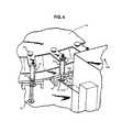
- FIG. 1is a perspective view of a housing that contains an automated drug delivery system that prepares a dosage of medication to be administered to a patient;
- FIG. 2is a diagrammatic plan view of the automated system for preparing a medication to be administered to a patient
- FIG. 3is a local perspective view of an automated device for removing or replacing the safety tip cap from the syringe
- FIG. 4is a local perspective view of a device for extending a plunger of the syringe
- FIG. 5is a local perspective view of fluid transfer and vial preparation equipment in a fluid transfer area of the automated system
- FIG. 6is a local perspective view of first and second fluid delivery devices that form a part of the system of FIG. 2 ;
- FIG. 7is a local perspective view of a multi-use vial holding station and a vial weigh station
- FIG. 8is a top plan view of a drug vial
- FIG. 9is a cross-sectional view of a drug vial with a vented cannula in a first position where the vent is active;
- FIG. 10is a cross-sectional view of a drug vial with the vented cannula in a second position where the vent is inactive;
- FIG. 11is a perspective view of a syringe with its cap removed contained in a sealed package
- FIG. 12is a perspective view of a syringe with it cap attached contained in a sealed package
- FIG. 13is a cross-sectional view of drug delivery directly from a drug vial by extending the plunger of a syringe with an automated mechanism;
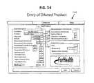
- FIG. 14is a computer screen image of an input page for entering information related to a drug dilution order
- FIG. 15is a graph of the data obtained by a load cell for determining a weight of the contents of the vial to ensure proper reconstitution of the medication
- FIG. 16Ais a side cross-sectional view of laser assembly for determining a liquid volume in a syringe or the like;
- FIG. 16Bis a side cross-sectional view of a camera view of the syringe with an offset laser line that represents the location of the liquid;
- FIG. 17is a side cross-sectional view of an apparatus for measuring fluid level by water absorbance
- FIG. 18is a side cross-sectional view of an apparatus for measuring fluid volume by capacitive sensors
- FIG. 19is a side cross-sectional view of an apparatus for measuring fluid level with a camera
- FIG. 20is a schematic view of a motion control system for controlling movement of a cannula and its interaction with another object;
- FIG. 21is a schematic view of the parts of a cannula
- FIG. 22is a schematic view of the parts of a drug vial
- FIGS. 23 a - gshow various types of cannula interactions with a septum of the vial
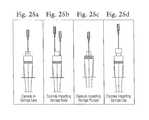
- FIGS. 24 a - eshow various types of cannula interactions with a vial
- FIGS. 25 a - dshow various types of cannula interactions with a syringe.
- FIG. 1is perspective view of a housing 1300 that is constructed to house an automated drug preparation and delivery system 100 in a sealed, controlled environment when the housing structure is closed (sealed).
- a user interface, such as a computer, 1303is provided to permit an operator not only to enter information, such as drug orders, but also to monitor the progress and operation of the system 100 .
- the housing 1300 and its componentsare described in greater detail below.
- FIG. 2is a schematic diagram illustrating one exemplary automated system, generally indicated at 100 , for the preparation of a medication.
- the automated system 100is divided into a number of stations where a specific task is performed based on the automated system 100 receiving user input instructions, processing these instructions and then preparing unit doses of one or more medications in accordance with the instructions.
- the automated system 100includes a station 110 where medications and other substances used in the preparation process are stored.
- the term “medication”refers to a medicinal preparation for administration to a patient. Often, the medication is initially stored as a solid, e.g., a powder, to which a diluent is added to form a medicinal composition.
- the station 110functions as a storage unit for storing one or medications, etc., under proper storage conditions.
- medications and the likeare stored in sealed containers, such as vials, that are labeled to clearly indicate the contents of each vial.
- the vialsare typically stored in columns and further, empty vials can be stored in one column.
- the station 110includes a mechanism that permits the controlled discharge of a selected drug vial 60 .
- a first station 120is a syringe storage station that houses and stores a number of syringes. For example, up to 500 syringes or more can be disposed in the first station 120 for storage and later use.
- the first station 120can be in the form of a bin or the like or any other type of structure than can hold a number of syringes.
- the syringesare provided as a bandolier structure that permits the syringes to be fed into the other components of the system 100 using standard delivery techniques, such as a conveyor belt, etc.
- the system 100also includes an apparatus 130 for advancing the fed syringes to and from various stations of the system 100 .
- the apparatus 130can be a rotary device, as shown, or it can be a linear apparatus, or it can assume some other shape.
- the apparatus 130is discussed and shown as being a rotary device; however, it is not limited to such a configuration and therefore, the present disclosure is not limiting of the scope of the present invention.
- a number of the stationsare arranged circumferentially around the rotary apparatus 130 so that the syringe is first loaded at the first station 120 and then rotated a predetermined distance to a next station, etc., as the medication preparation process advances. At each station, a different operation is performed with the end result being that a unit dose of medication is disposed within the syringe that is then ready to be administered.
- One exemplary type of rotary apparatus 130is a multiple station cam-indexing dial that is adapted to perform material handling operations.
- the indexeris configured to have multiple stations positioned thereabout with individual nests for each station position.
- One syringeis held within one nest using any number of suitable techniques, including opposing spring-loaded fingers that act to clamp the syringe in its respective nest.
- the indexerpermits the rotary apparatus 130 to be advanced at specific intervals.
- the syringesare loaded into one of the nests or the like of the rotary apparatus 130 .
- One syringeis loaded into one nest of the rotary apparatus 130 in which the syringe is securely held in place.
- the system 100preferably includes additional mechanisms for preparing the syringe for use, such as removing a tip cap and extending a plunger of the syringe at a third station 150 as described below. At this point, the syringe is ready for use.
- the system 100also preferably includes a reader 151 that is capable of reading a label disposed on the sealed container containing the medication.
- the labelis read using any number of suitable reader/scanner/camera devices 151 , such as a bar code reader, etc., so as to confirm that the proper medication has been selected from the storage unit of the station 110 .
- Multiple readerscan be employed in the system at various locations to confirm the accuracy of the entire process.
- the vial 60is prepared by removing the safety cap from the sealed container and then cleaning the exposed end of the vial.
- the safety capis removed on a deck of the automated system 100 having a controlled environment. In this manner, the safety cap is removed just-in-time for use.
- Exemplary vial cap removal devicesare disclosed in U.S. Pat. No. 6,604,903, which is hereby expressly incorporated by reference in its entirety.
- the vial capcan be removed by other devices, such as one which has a member with suction (vacuum) capabilities incorporated therein for removing the cap.
- the suction memberis applied to the vial cap and then the suction is activated and then the robotic arm that is gripping and hold the vial body itself is twisted while the drug vial cap is under suction, thus prying the cap from its seal.
- the capis still held by suction on the member until the suction is released at which time the cap falls into a trash bin.
- the system 100also preferably includes a fourth station (fluid transfer station) 170 for injecting or delivering a diluent into the medication contained in the sealed container and then subsequently mixing the medication and the diluent to form the medication composition that is to be disposed into the prepared syringe.
- the station 170can controllably deliver a predetermined dosage of pre-made medication.
- the prepared medication compositionis withdrawn from the container (i.e., vial) and is then delivered into the syringe.
- a cannulacan be inserted into the sealed vial and the medication composition then aspirated into a cannula set.
- the cannulais then withdrawn from the vial and is then rotated relative to the rotary apparatus 130 so that it is in line with (above, below, etc.) the syringe.
- the unit dose of the medication compositionis then delivered to the syringe, as well as additional diluent, if necessary or desired. This is referred to as a vial mode of operation where reconstitution of a drug is performed.
- the tip capis then placed back on the syringe at a station 180 .
- a station 190prints and station 195 applies a label to the syringe and a device, such as a reader, can be used to verify that this label is placed in a correct location and the printing thereon is readable.
- the readercan confirm that the label properly identifies the medication composition that is contained in the syringe and thus performs a safety check.
- the syringeis then unloaded from the rotary apparatus 130 at an unloading station 200 and delivered to a predetermined location, such as a new order bin, a conveyor, a sorting device, or a reject bin.
- a predetermined locationsuch as a new order bin, a conveyor, a sorting device, or a reject bin.
- the delivery of the syringecan be accomplished using a standard conveyor or other type of apparatus. If the syringe is provided as a part of the previously-mentioned syringe bandolier, the bandolier is cut prior at a station 198 located prior to the unloading station 200 .
- an initial labeling station 153 prior to the drug delivery station 170can be provided for applying a label with a unique identifier, such as a barcode, that uniquely identifies the syringe so that it can be tracked at any location as it is advanced from one station to another station.
- a reader 155 downstream of the initial labeling station 153reads the unique identifier and associates the unique identifier with this particular syringe 10 . This permits each drug order to be assigned one particular uniquely identified syringe which is logged into and tracked by the computer.
- a robotic deviceis provided for moving objects relative to the transporter device (dial 130 ) and in particular, the robotic device can deliver and/or remove objects, such as the syringe 10 or the drug vials 60 , relative to the dial 130 .
- the robotic devicethus typically has a gripper mechanism, such as a pair of grippers, for grasping and holding the object.
- FIGS. 2-5illustrate parts of the third station 150 for preparing a syringe 10 , the fluid transfer station 170 , and the station 180 for preparing the syringe for later use.
- a conventional syringe 10includes a barrel 20 into which fluid is injected and contained and at a barrel tip, a cap 40 is provided to close off the barrel 20 .
- a plunger 50is slidingly received within the barrel 20 for both drawing fluid into the barrel and discharging fluid therefrom.
- FIGS. 2-5thus illustrate in more detail the stations and automated devices that are used in removal of the tip cap 40 from the barrel tip, the filling of barrel chamber with medication and the replacement of the tip cap 40 on the barrel tip.
- FIG. 3is a perspective view of an automated device 300 at station 150 that removes the tip cap 40 from the barrel tip as the syringe 10 is prepared for receiving a prescribed dose of medication at station 170 of the automated medication preparation system 100 .
- the device 300is a controllable device that is operatively connected to a control unit, such as a computer, which drives the device 300 to specific locations at selected times.
- the control unitcan be a personal computer that runs one or more programs to ensure coordinated operation of all of the components of the system 100 .
- one exemplary rotary device 130is a multiple station cam-indexing dial that is adapted to perform material handling operations.
- the dial 130has an upper surface 132 and means 134 for securely holding one syringe 10 in a releasable manner and in a spaced relationship.
- Exemplary means 134is disclosed in U.S. Pat. No. 6,915,823, which is incorporated herein by reference in its entirety.
- a post 161is provided for holding the tip cap 40 after its removal to permit the chamber to be filled with medication.
- the post 161can also be formed on the upper surface 132 of the dial 130 .
- the precise location of the post 161can vary so long as the post 161 is located where the tip cap 40 can sit without interfering with the operation of any of the automated devices and also the post 161 should not be unnecessarily too far away from the held syringe 10 since it is desired for the automated devices to travel a minimum distance during their operation to improve the overall efficiency of the system 100 .
- the specific shape of the post 161can likewise vary so long as the post 161 can hold the tip cap 40 so that it remains on the post 161 during the rotation of the dial 130 as the associated syringe 10 is advanced from one station to another station.
- the syringes 10are fed to the rotary device 130 as part of a syringe bandolier (i.e., multiple syringes 10 are disposed in series and interconnected by a web), it will be appreciated that the syringes 10 can be fed to the rotary device 130 in any number of other ways.
- the syringes 10can be fed individually into and held individually on the rotary device 130 from a loose supply of syringes 10 .
- the automated device 300is a robotic device and preferably, the automated device 300 is a linear actuator with a gripper.
- the device 300has first and second positionable gripping arms 340 , 350 which are adjustable in at least one direction and which are coupled to and extend downwardly from the block member 330 .
- each of the gripping arms 340 , 350is movable at least in a direction along the y axis which provide the flexibility and motion control that is desirable in the present system 100 .
- the gripping arms 340 , 350are programmed to work together in tandem so that both arms 340 , 350 are driven to the same location and the same time. This permits an object, such as the cap 40 , to be held and moved to a target holding location.
- the gripper device 300can be any robotic device that can hold and move an object, such as the tip cap 40 , from one location to another location.
- the system 100also includes a device 400 for extending the plunger 50 of one uncapped syringe 10 after it has had its tip cap 40 removed therefrom.
- the device 400as well as the device 300 , are described as being part of the third station 150 of the system 100 .
- the device 400extends the plunger 50 so that the syringe 10 can receive a desired dose based upon the particular syringe 10 being used and the type of application (e.g., patient's needs) that the syringe 10 is to be used for.
- the device 400can have any number of configurations so long as it contains a feature that is designed to make contact with and withdraw the plunger 50 .
- the automated device 400is a robotic device and preferably, the automated device 400 is a linear actuator with a gripper.
- one exemplary device 400is a mechanical device that has a movable gripper 410 that includes a gripping edge 420 that engages the flange 54 of the plunger 50 , as shown in FIG. 4 , and then the gripper 410 is moved in a downward direction causing the plunger 50 to be moved a predetermined amount.
- the gripper 410can be the part of an extendable/retractable arm that includes the gripping edge 420 for engaging the syringe 10 above the plunger flange 54 .
- an actuator or the likee.g., stepper motor
- the gripper 410moves laterally away from the plunger 50 so that the interference between the flange 54 of the plunger 50 and the gripping edge 420 no longer exits.
- the gripper 410is free of engagement with the plunger 50 and can therefore be positioned back into its initial position by being moved laterally and/or in an up/down direction (e.g., the gripper 410 can move upward to its initial position).
- An exemplary plunger extending deviceis described in commonly assigned U.S. patent application Ser. No. 10/457,066, which is hereby incorporated by reference in its entirety.
- the device 400complements the device 300 in getting the syringe 10 ready for the fluid transfer station at which time, a prescribed amount of medication or other medication is dispensed into the chamber 30 of the barrel 20 as will be described in greater detail hereinafter.
- the syringes 10can be provided without caps 40 and thus, the device 300 is not needed to remove caps 40 if the syringes 10 are loaded onto dial 130 without caps 40 .
- the device 400is part of the overall programmable system and therefore, the distance that the gripper 410 moves corresponds to a prescribed movement of the plunger 50 and a corresponding increase in the available volume of the chamber of the barrel 20 .
- the controllerinstructs the device 400 to move the gripper 410 a predetermined distance that corresponds with the plunger 50 moving the necessary distance so that the volume of the barrel chamber is at least 8 ml. This permits the unit dose of 8 ml to be delivered into the barrel chamber.
- the device 400can be operated multiple times with reference to one syringe 10 in that the plunger 50 can be extended a first distance during a first operation of the device 400 and a second distance during a subsequent second operation of the device 400 .
- the syringe 10is then delivered to the fluid transfer station 170 where a fluid transfer device 500 prepare and delivers the desired amount of medication.
- FIG. 5a drug preparation area is illustrated in greater detail to show the individual components thereof. More specifically, a drug transfer area for the vial mode of operation of the system 100 is illustrated and is located proximate the rotary dial 130 so that after one drug vial 60 is prepared (reconstituted), the contents thereof can be easily delivered to one or more syringes 10 that are securely held in nested fashion on the rotary dial 130 .
- drug vials 60are stored typically in the storage cabinet 110 and can be in either liquid form or solid form or even be empty.
- a driven membersuch as a conveyor belt 111 , delivers the drug vial 60 from the cabinet 110 to a first robotic device (e.g., a pivotable vial gripper mechanism) 510 that receives the vial 60 in a horizontal position and after gripping the vial with arms (grippers) or the like, the mechanism 510 is operated so that the vial 60 is moved to a vertical position relative to the ground and is held in an upright manner.
- a first robotic devicee.g., a pivotable vial gripper mechanism
- 510that receives the vial 60 in a horizontal position and after gripping the vial with arms (grippers) or the like, the mechanism 510 is operated so that the vial 60 is moved to a vertical position relative to the ground and is held in an upright manner.
- the mechanism 510is designed to deliver the vial 60 to a rotatable pedestal 520 that receives the vial 60 once the grippers of the mechanism 510 are released.
- the vial 60sits upright on the pedestal 520 near one edge thereof that faces the mechanism 510 and is then rotated so that the vial 60 is moved toward the other side of the pedestal 520 . It will be understood that any number of different robotic mechanisms can be used to handle, move and hold the vial.
- the vial 60is scanned as by a barcode reader 151 or the like and preferably a photoimage thereof is taken and the vial 60 is identified. If the vial 60 is not the correct vial, then the vial 60 is not used and is discarded using a gripper device that can capture and remove the vial 60 from the pedestal before it is delivered to the next processing station.
- the central controlhas a database that stores all the identifying information for the vials 60 and therefore, when a dose is being prepared, the controller knows which vial (by its identifying information) is to be delivered from the cabinet 110 to the pedestal 520 .
- the vialis automatically discarded (e.g., returned to a further inspection station) and the controller will instruct the system to start over and retrieve a new vial.
- the readersuch as a scanner, 151 can also read the vial 60 to ensure that the proper vial 60 has been delivered and gripped by the robotic device. This is another safety check and can be implemented with barcodes or the like.
- the reader 151initially reads the barcode or other identifying information contained on the vial 60 and this read information is compared to a stored database that contains the inputted drug information. If the product identification information does not match, the operator is notified and the vial 60 is not advanced to the next station.
- a vial gripper device (robotic device) 530moves over to the pedestal for retrieving the vial 60 (alternatively, this robotic device can be the same robotic device that delivers the vial 60 to the pedestal).
- the vial gripper device 530is configured to securely grip and carry the vial in a nested manner to the next stations as the drug is prepared for use. Details and operation of the vial gripper device 530 are described in detail in U.S. patent application Ser. No. 11/434,850, which is hereby incorporated by reference in its entirety.
- the robotic device 530includes a pair of grippers or arms 539 (gripper unit) that are positionable between closed and open positions with the vial 60 being captured between the arms in the closed position in such a manner that the vial 60 can be securely moved and even inverted and shaken without concern that the vial 60 will become dislodged and fall from the arms.
- the armsthus have a complementary shape as the vial 60 so that when the arms close, they engage the vial and nest around a portion (e.g., neck portion) of the vial 60 resulting in the vial 60 being securely captured between the arms.
- the armscan be pneumatically operated arms or some other mechanical devices.
- the device 530In order to retrieve the vial 60 from the pedestal 520 , the device 530 is driven forward and then to one side so that it is position proximate the pedestal 520 .
- the gripper unit 539is then moved downward so that the arms, in their open position, are spaced apart with the vial 60 being located between the open arms.
- the gripper unit 539is then actuated so that the arms close and capture the vial 60 between the arms.
- the robotic device 530is moved upward and the device 530 is driven back to the opposite side so as to introduce the vial 60 to the next station.
- the vial 60is also inverted by inversion of the gripper unit 539 so that the vial 60 is disposed upside down.
- the vial 60can then be delivered to a weigh station 540 ( FIG. 7 ) where the weight of the vial with solid medication (or an empty vial or any other object) is measured and stored in the computer system.
- a weigh station 540FIG. 7
- Load cell 542is a transducer for the measurement of force or weight, usually based on a strain gauge bridge or vibrating wire sensor.
- the load cell 542includes a housing or body 544 that contains the working components and electronics of the load cell 542 and a platform 546 on which the item, in this case, the vial, to be weighed is placed.
- the load cell 542is part of an overall automated and integrated system and therefore, it contains software that communicates with the master controller so that the operation of the complete system 100 can be controlled, including the movement of the robotic device 530 that holds and transport the vial 60 from one location to another location. As shown in FIG. 7 , the vial 60 is held by the robotic device about the neck portion and can therefore be delivered onto the load cell platform 546 . In one embodiment, the robotic device moves the vial 60 from the pedestal 520 to the platform 546 .
- the software controlling the robotic deviceis configured so that the vial grippers of the robotic device are first approximately level with the standby pedestal 520 and at this point, the software of the load cell gather a predetermined number, such as 10-15 (e.g., 15) weights from the load cell 542 which are considered the tare weight.
- the vial 60is then shuttled down to a predetermined distance, such as 2.5 mm, above the load cell platform 546 . From this predetermined distance (e.g., 2.5 mm), the load cell software shuttles the vial 60 down towards the load cell platform 546 very slowly, while monitoring the weights returned by the load cell 542 to determine the exact moment the vial makes contact with the platform 546 (i.e., which will register a marked increase in observed weight).
- the softwareinstructs the vial grippers to open and all vertical movement of the vial is stopped.
- a predetermined timesuch as 0.5 seconds, after the vial grippers open, the software collects a predetermined number, such as 10-15 (e.g., 15) of weight measurements from the load cell, which shall be considered the weight of the vial and the load cell platform.
- the data collected by the load cellcan be processed in any number of different ways and in one embodiment, as shown in FIG. 15 , a graph is created where the x axis is the measured amplitude (AtoD counts) and the y axis is the time (ms). The point at which the vial makes contact with the load cell 542 is indicated at line 545 .
- the vial weight (AtoD counts)is equal to the measured weight-tare.
- the vial weight (grams)is equal to (vial weight (AtoD counts)*slope)+intercept.
- datais not displayed but is manipulated inside the master controller and final results are used for system reaction.
- empty child vial weighed and diluentis added and weighed. After that, drug is added to the vial with diluent and weighed. Now the system knows the amount of diluent and drug added to the vial and knows the final composition of the drug in the vial.
- the inverted vial 60is delivered to a station 550 where the vial 60 is prepared by removing the safety cap from vial 60 after vial verification when the vial is introduced into the system 100 but before the tare weight and the filling of diluent and final weighing of the product as described above.
- This station 550can therefore be called a vial decapper station. Any number of devices can be used at station 550 to remove the safety cap from the vial. For example, several exemplary decapper devices are disclosed in commonly-assigned U.S. Pat. No. 6,604,903 which is hereby incorporated by reference in its entirety.
- the vial 60is then delivered, still in the inverted position, to a cleaning station 560 where the exposed end of the vial is cleaned.
- a cleaning station 560can be in the form of a swab station that has a wick saturated with a cleaning solution, such as an alcohol.
- the exposed area of the vial 60is cleaned by making several passes over the saturated wick which contacts and baths the exposed area with cleaning solution.
- the gripper unit 539rotates so that the vial 60 is returned to its upright position and remains held between the gripper arms.
- the device 530then advances forward to the fluid transfer station 170 according to one embodiment.
- the fluid transfer station 170is an automated station where the medication (drug) can be processed so that it is in a proper form for delivery (injection) into one of the syringes 10 that is coupled to the rotary dial 130 .
- the fluid transfer station 170is used during operation of the system, at least partially, in a vial mode of operation.
- a diluente.g., water or other fluid
- the fluid transfer stationis a station where a precise amount of medication is simply aspirated or withdrawn from the vial 60 and delivered to the syringe 10 .
- the reconstitution processis first described.
- the vial 60 containing a prescribed amount of solid medicationis delivered in the upright position to the fluid transfer station 170 by the device 530 .
- the device 530has a wide range of movements in the x, y and z directions and therefore, the vial 60 can easily be moved to a set fluid transfer position.
- the vial 60remains upright and a fluid transfer device 580 is brought into position relative to the vial 60 so that an automated fluid transfer can result therebetween.
- the fluid transfer device 580is the main means for both discharging a precise amount of diluent into the vial 60 to reconstitute the medication and also for aspirating or withdrawing the reconstituted medication from the vial 60 in a precise, prescribed amount.
- the device 580is a controllable device that is operatively connected to a control unit, such as a computer, which drives the device 580 to specific locations at selected times and controls with a high degree of precision the operation and discharge of medication.
- the control unitcan be a personal computer that runs one or more programs to ensure the coordinated operation of all of the components of the system 100 .
- one exemplary fluid transfer device 580is a robotic device having a movable cannula unit 590 that can be moved in a controlled up and down and side-side, etc., manner so to either lower it or raise it relative to the vial 60 in the fluid transfer position and to move it into the proper position.
- the cannula unit 590can be pneumatically operated or operated by an electric motor or some other means to cause the controlled movement of the cannula unit 590 .
- a cannula 610is provided at one end of the cannula unit 590 .
- the cannula 610has one end that serves to pierce the septum of the vial 60 and an opposite end that is connected to a main conduit 620 that serves to both deliver diluent to the cannula 610 and ultimately to the vial 60 and receive aspirated reconstituted medication from the vial 60 .
- the cannula 610is of the type that is known as a vented cannula which can be vented to atmosphere as a means for eliminating any dripping or spattering of the medication during an aspiration process.
- the use of a vented needle to add (and withdraw) the fluid to the vialovercomes a number of shortcoming associated with cannula fluid transfer and in particular, the use of this type of needle prevents backpressure in the vial (which can result in blow out or spitting or spraying of the fluid through the piercing hole of the cannula).
- the ventingtakes place via an atmospheric vent that is located in a clean air space and is formed in a specially designed hub that is disposed over the needle.
- the venting actionis a form of drip control (spitting) that may otherwise take place.
- Drip controlis thus a feature in the system 100 after aspiration where fluid is sucked back into the tube (cannula) to prevent dripping of the drug and then the cannula 610 is transferred to the syringe 10 for dispensing.
- the cannula 610is also preferably of the type that is motorized so that the tip of the cannula 610 can move around within the vial 60 so that cannula 610 can locate and aspirate every last drop of the medication.
- the cannula 610itself is mounted within the cannula unit 590 so that it can move slightly therein such that the tip moves within the vial and can be brought into contact with the medication wherever the medication may lie within the vial 60 .
- the cannula 610is driven so that it can be moved at least laterally within the vial 60 .
- An opposite end of the main conduit 620is connected to a fluid pump system 630 that provides the means for creating a negative pressure in the main conduit 620 to cause a precise amount of fluid to be withdrawn into the cannula 610 and the main conduit 620 , as well as creating a positive pressure in the main conduit 620 to discharge the fluid (either diluent or medication) that is stored in the main conduit 620 proximate the cannula 610 .
- a fluid pump system 630as well as the operation thereof, is described in great detail in the '823 patent, which has been incorporated by reference.
- the net resultis that the prescribed amount of diluent that is needed to properly reconstitute the medication is delivered through the cannula 610 and into the vial 60 . Accordingly, the cannula 610 pierces the septum of the vial and then delivers the diluent to the vial and the vial 60 can be inverted to cause agitation and mixing of the contents of the vial or the vial can be delivered to a separate mixing device to cause the desired mixing of the contents.
- the fluid pump system 630is then operated so that a prescribed amount of medication is aspirated or otherwise drawn from the vial 60 through the cannula 610 and into the main conduit 620 .
- an air bubbleis introduced into the main conduit 620 to serve as a buffer between the diluent contained in the conduit 620 to be discharged into one vial and the aspirated medication that is to be delivered and discharged into one syringe 10 . It will be appreciated that the two fluids (diluent and prepared medication) can not be allowed to mix together in the conduit 620 .
- the air bubbleserves as an air cap in the tubing of the cannula and serves as an air block used between the fluid in the line (diluent) and the pulled medication.
- the air blockis a 1/10 ml air block; however, this volume is merely exemplary and the size of the air block can be varied.
- the fluid transfer device 580is rotated as is described below to position the cannula 610 relative to one syringe 10 that is nested within the rotary dial 130 .
- the pump mechanism 630is actuated to cause the controlled discharge of the prescribed amount (dosage) of medication through the cannula 610 .
- the air blockcontinuously moves within the main conduit 620 toward the cannula 610 .
- the air blockWhen all of the pulled (aspirated) medication is discharged, the air block is positioned at the end of the main conduit signifying that the complete pulled medication dose has been discharged; however, none of the diluent that is stored within the main conduit 620 is discharged into the syringe 10 since the fluid transfer device 580 , and more particularly, drivers or the like of the system, operate with such precision that only the prescribed medication that has been previously pulled into the main conduit 620 is discharged into the vial 60 .
- the fluid transfer device 580may need to make several aspirations and discharges of the medication into the vial 60 in order to inject the complete prescribed medication dosage into the vial 60 .
- the cannula unit 590can operate to first aspirate a prescribed amount of fluid into the main conduit 620 and then is operated so that it rotates over to and above one syringe 10 on the rotary dial 130 , where one incremental dose amount is discharged into the vial 60 . After the first incremental dose amount is completely discharged into the syringe 10 , the cannula unit 590 is brought back the fluid transfer position where the fluid transfer device is operated so that a second incremental dose amount is aspirated into the main conduit 620 in the manner described in detail hereinbefore.
- the cannula unit 590is brought back to the rotary dial 130 above the syringe 10 that contains the first incremental dose amount of medication.
- the cannula 610is then lowered so that the cannula tip is placed within the interior of the syringe 10 and the cannula unit 590 is operated so that the second incremental dose amount is discharged into the syringe 10 .
- the processis repeated until the complete medication dose is transferred into the syringe 10 .
- the cannula unit 590can be configured so that it can be operated at varying speeds of aspiration.
- the software associated with the cannula unit 590can offer the operator a number of different aspiration programs to choose from or the operator can program the unit 590 with a unique aspiration process or program by entering or inputting aspiration instructions.
- the unit 590can operate by first aspirating the medication at a first speed and for a first time period and then aspirating the medication at a second speed for a second time period.
- the first speedis greater than the second speed and the first time period is greater than the second time period; however, the opposite can be equally true and it will further be appreciated that there may be more than 2 distinct aspiration phases.
- the speed of the aspirationcan be varied by simply varying the speed of the pump. In this manner, the initial aspiration of the medication can operate at a higher speed and then when only a small amount of medication remains, the aspiration speed can be reduced so as to controllably withdraw the last portion of the medication that is contained in the container.
- the reconstitution equipmentincluding the cannula unit 590
- can possess various motionsincluding a gentle inversion to “wet” the solid drug in the vial 60 with the diluent that was added to the vial 60 and an agitation motion which causes the drug to go into solution.
- the system 100and in particular, the reconstitution module thereof, is configured to operate in this manner since the reconstitution process uses both motions based upon key drug characteristics.
- a databasecontrols the differences observed from drug to drug.
- the robotic gripperholds the drug vial 60 during the agitation cycle so that is does not become dislodged.
- the associated softwarepreferably possesses a QA function that enables the drug to be tested under various conditions to assure that the settings effect putting the drug into solution, and the ability to have the reconstituted drug manually observed, by the robotic gripper removing the drug from the reconstitution station 170 and presenting the vial 60 to a window (when the system 100 is contained within an enclosed structure as described below) for an operator to look at the vial 60 and enter their observations into a reconstitution QA database. If the drug was not fully in solution, the entry into the QA database can be used to adjust the formulary to require an additional increment of agitation time.
- the softwareis designed so that once the operator enters the drug order, the master controller accesses the reconstitution database that includes detailed instructions as to how to prepare the reconstituted drug of the order and part of these instructions include instructions on the aspiration process as discussed below.
- the aspiration instructionsare determined, including the number, length and characteristics of the agitation phases and motions, and then the controller instructs the equipment to execute these instructions.
- a prescribed dosage of medicationcan be drawn from the vial 60 by mating a syringe 10 with the vial 60 as by inserting the needle (vented cannula) of the syringe into and through the septum of the vial 60 and then extending the plunger a predetermined, precise distance so as to draw a precise amount dosage into the syringe from the drug vial 60 .
- the device and method for controlling the extension of the plungeris described in great detail herein.
- the vial 60 that is positioned at the fluid transfer positioncan either be (1) discarded or (2) it can be delivered to a holding station 700 where it is cataloged and held for additional future use. More specifically, the holding station 700 serves as a parking location where a vial that is not completely used can be used later in the preparation of a downstream syringe 10 .
- the vials 60 that are stored at the holding station 700are labeled as multi-use medications that can be reused. These multi-use vials 60 are fully reconstituted so that at the time of the next use, the medication is only aspirated from the vials 60 as opposed to having to first inject diluent to reconstitute the medication.
- the usercan easily input into the database of the master controller which medications are multi-use medications and thus when the vial 60 is scanned and identified prior to being delivered to the fluid transfer position, the vial 60 is identified and marked as a multi-use medication and thus, once the entire medication dose transfer has been performed, the vial gripper device 530 is instructed to deliver the vial 60 to the holding station 700 .
- multi-use medicationsare those medications that are more expensive than other medications and also are those medications that are used in larger volumes (quantities) or are stored in larger containers and therefore come in large volumes.
- the holding station 700is simply a location where the multi-use vials can be easily stored.
- the holding station 700is preferably a shelf or even a cabinet that contains a flat surface for placing the vials 60 .
- a grid with distinct coordinatescan be created to make it easy to determine where each vial 60 is stored within the holding station 700 .
- the gripper unitis operated so that the arms thereof release the vial 60 at the proper location.
- the device 530then returns back to its default position where it can then next be instructed to retrieve a new vial 60 from the pedestal 520 .
- the vial 60 at the fluid transfer positionis discarded.
- the device 530moves such that the vial 60 is positioned over a waste chute or receptacle and then the gripper unit is actuated to cause the vial 60 to drop therefrom into the waste chute or receptacle.
- the device 530is then ready to go and retrieve a new vial 60 that is positioned at the pedestal 520 for purposes of either reconstituting the medication or simply aspirating an amount of medication therefrom or a vial from the holding station 700 can be retrieved.
- the vial 60can be further agitated using a mixing device or the like 710 .
- the mixing device 710is a vortex type mixer that has a top surface on which the vial 60 is placed and then upon actuation of the mixer, the vial 60 is vibrated or otherwise shaken to cause all of the solid medication to go into solution or cause the medication to be otherwise mixed.
- the mixing deviceis a mechanical shaker device, such as those that are used to hold and shake paint cans.
- the vial 60can be placed on support surface of the shaker and then an adjustable hold down bar is manipulated so that it travels towards the vial and engages the vial at an end opposite the support surface.
- the shaker deviceis actuated resulting in the vial 60 being shaken to agitate the medication and ensure that all of the medication properly goes into solution.
- the mixing device 710can also be configured so that it is in the form of a robotic arm that holds the vial by means of gripper members (fingers) and is operatively connected to a motor or the like which serves to rapidly move the arm in a back and forth manner to cause mixing of the medication.
- reconstitutionis done using a process commonly called “milking”. In this process, diluent is added to the drug vial to be reconstituted and with series of “pull and push” motion of fluid, reconstitution is achieved. In this process, non-venting needle is used.
- the entire system 100is integrated and automated and also utilizes a database for storing identifying data, mixing instructions, and other information to assist in the preparation of the medication. There are also a number of safety features and check locations to make sure that the medication preparation is proceeding as it should.
- the databaseincludes identifying information so that each vial 60 and syringe 10 can be carefully kept track of during each step of the process.
- the reader (e.g., barcode scanner) 151 and the photoimaging equipmentserve to positively identify the vial 60 that is delivered from the drug storage 110 .
- the userwill enter one or more medication preparation orders where the system 100 is instructed to prepare one or more syringes that contain specific medication. Based on this entered information or on a stored medication preparation order that is retrieved from a database, the vial master controller determines at which location in the cabinet the correct vial 60 is located.
- That vial 60is then removed using a robotic gripper device (not shown) and is then placed on the conveyor belt 111 and delivered to the mechanism 510 pivots upright so that the vial 60 is moved a vertical position relative to the ground and is held in an upright manner and is then delivered to the rotatable pedestal 520 .
- the vial 60is scanned to attempt to positively identify the vial 60 and if the scanned identifying information matches the stored information, the vial 60 is permitted to proceed to the next station. Otherwise, the vial 60 is discarded.
- the master controllerserves to precisely calculate how the fluid transfer operation is to be performed and then monitors the fluid transfer operations has it is occurring. More specifically, the master controller first determines the steps necessary to undertake in order to perform the reconstitution operation. Most often during a reconstitution operation, the vial 60 that is retrieved from the drug storage 110 contains a certain amount of medication in the solid form. In order to properly reconstitute the medication, it is necessary to know what the desired concentration of the resulting medication is to be since this determines how much diluent is to be added to the vial 60 .
- one piece of information that the user is initially asked to enteris the concentration of the medication that is to be delivered to the patient as well as the amount that is to be delivered.
- the master controlleris able to calculate how much diluent is to be added to the solid medication in the vial 60 to fully reconstitute the medication.
- the databasealso preferably includes instructions as to the mixing process in that the mixing device is linked to and is in communication with the master controller so that the time that the mixing device is operated is stored in the database such that once the user inputs the medication that is to be prepared and once the vial 60 is scanned and identified, the system (master controller or CPU thereof) determines the correct time that the vial 60 is to be shaken to ensure that all of the medication goes into solution.
- the master controllerdetermines and instructs the working components on how the reconstitution operation should proceed, the master controller also calculates and prepares instructions on how many distinct fluid transfers are necessary to deliver the prescribed amount of medication from the vial 60 to the syringe 10 .
- the cannula unit 590may not be able to fully aspirate the total amount of medication from the vial 60 in one operation and therefore, the master controller determines how many transfer are needed and also the appropriate volume of each aspiration so that the sum of the aspiration amounts is equal to the amount of medication that is to be delivered to the syringe 10 .
- the master controllerinstructs and controls the operation of the pump mechanism so that the precise amounts of medication are aspirated and then discharged into the syringe 10 .
- the pump mechanismoperates to cause the proper dose amount of the medication to be first aspirated from the vial and then discharged into the syringe. This process is repeated as necessary until the correct dose amount is present in the syringe 10 in accordance with the initial inputted instructions of the user.
- multiple dosesare aspirated from the vial and smaller doses are dispensed into multiple syringes.
- the master controllerinstructs the rotary dial to move forward in an indexed manner so that the next empty syringe 10 is brought into the fluid transfer position.
- the cannula 610is also preferably cleaned after each medication dose transfer is completed so as to permit the cannula 610 to be reused.
- the cannula 610is rotated and positioned so that the needle of the cannula 610 is lowered into a bath so that fluid is expelled between the inside hubs of the syringe 10 for cleaning of the interior components of the cannula 610 .
- the cannula 610is then preferably dipped into a bath or reservoir to clean the outside of the cannula 610 . In this manner, the cannula 610 can be fully cleaned and ready for a next use without the need for replacement of the cannula 610 , which can be quite a costly endeavor.
- a medication sourcesuch as a bag that is filled with liquid medication that has already been properly reconstituted, is connected to an input portion of a peristaltic pump by means of a first conduit section.
- a second conduit sectionis connected to an output port of the pump and terminates in a connector.
- the connectoris of the type that is configured to hermetically seal with an open barrel tip of the syringe 10 that is nested within the rotary dial 130 and is marked to receive medication.
- the connectortypically includes a conduit member (tubing) that is surrounded by a skirt member or the like that mates with the outer hub of the syringe barrel.
- a flange or diaphragmcan be provided for hermetically sealing with the syringe barrel (outer hub).
- the medication sourcee.g., an IV bag
- the plunger 50is pulled a precise distance that results in the correct size cavity being opened up in the barrel for receiving the fluid but also the extension of the plunger creates enough negative pressure to cause the medication to be drawn into the syringe barrel.
- Thisis thus an alternative means for withdrawing the proper amount of medication from a member (in this case the source) and transferring the desired, precise amount of medication to the syringe 10 .
- this alternative embodimentcan be referred to as operating the system in reservoir mode and is shown in FIG. 13 .
- One advantage of this embodimentis that multiple syringe drivers or the like or some type of pump mechanism are not needed to pump the medication into the syringe 10 but rather the drawing action is created right at the rotary dial 130 . This design is thus fairly simple; however, it is not suitable for instances where drug reconstitution is necessary.
- the sourcedoes not have to be a medication source in that it does not have to contain an active drug but instead, the source can contain diluent that is to be drawn in a prescribed volume into the syringe, especially for purposes of serial dilution, as described below.
- the fluid sourcein the reservoir mode, can consist of a number of drug delivery bags 750 that are already filled either premixed medication or with only diluent that is later used to dilute medication as described in detail below.
- the filled drug delivery bags (e.g., IV bags) 750can be hung in a select area, with each bag 750 having an outlet conduit through which the fluid contained in the bag is drawn.
- outlet conduits associated with the drug delivery bags 750can be interconnected as by connecting each of the bag outlet conduits to a common line 754 with one or more valves or the like being used to selectively control which bag outlet line is in directly fluid communication with the common line 754 .
- a number of different medicationscan be hung and be ready for use and the user of the system merely has to manipulate the valve (either manually or automatically using a computer, etc.) to connect the selected bag 750 to the common line 754 .
- the computer that operates the entire systemcan be in communication with the valves to permit and to control the flow of the prescribed desired fluid from one bag 750 to the common line 754 .
- the common line 754is thus in communication at a first end with the outlet conduit of the select bag 750 that contains the desired fluid and another end of the common line 754 is configured to mate with a syringe inlet port to permit the fluid in the bag 750 to be drawn into the bag by extending the plunger 50 a predetermined distance as described above to cause a precise, target volume of fluid to be drawn into the barrel of the syringe 10 .
- the free end of the common line (conduit) 754can contain a connector or adapter (e.g., a stopper element) 760 that is configured to mate with the inlet opening (port) of the syringe barrel in a sealed manner. Since it is the extension of the plunger 50 that generates the means of drawing a prescribed volume of fluid into the syringe barrel, the connection between the end of the common line (e.g., the connector thereof) and the syringe barrel is such that the creation of negative pressure in the syringe barrel 20 causes the fluid to be drawn into the barrel. In other words, it is desirable to establish a seal or the like between the end of the common line 754 and the syringe barrel so that negative pressure can be established and maintained in the syringe barrel.
- a connector or adaptere.g., a stopper element
- the delivery of fluid from one source during operation of the reservoir mode to one syringe 10is performed at the reservoir mode fluid delivery station 770 that is arranged relative to the other stations of the system 100 .
- the free end of the common line 754is secured to a controllable, movable device, 765 such as a robotic arm or an automated arm, that can be controllably moved.
- the movable deviceis moved vertically at least along a linear axis so as to drive the free end of the common line 754 (the connector) into a sealed coupling with the syringe barrel when it is driven in one direction or when it is driven in the opposite direction, the common line disengages from the barrel of the syringe 10 to permit the syringe to be advanced to another station, such as the fluid transfer station 170 described above where reconstituted drug can be delivered into a syringe 10 that was previously injected with fluid through the common line 754 from the fluid source when operating in reservoir mode.
- reservoir drug delivery station 770 and the fluid transfer station 170are different stations that are located at different locations, such as adjacent stations along the dial 130 .
- the capped syringe 10can then be transferred to other stations, such as a station where the syringe in bandolier form is cut into individual syringes 10 that are labeled for particular patients.
- the syringes 10can then be unloaded from the dial 130 and then further processed, as for example, by being delivered to a storage receptacle where it is stored or by being delivered to a transporting device for delivery to the patient or the filled syringes 10 can be cataloged and packaged in different boxes or the like for delivery to one more locations.
- a number of syringes 10can be prepared and delivered into a single box or receptacle.
- the system 100includes software that permits the user to enter (input) drug vial information which is then used to calculate and control the movement and position of the vented cannula 610 with respect to a septum 61 of the drug vial 60 .
- the vented cannula 610includes the drug delivery cannula portion and a separate air vent channel that terminates in a vent port proximate the open cannula portion.
- the vent portIn order for the vent portion to be in an active, open position, the vent port must be positioned within the interior chamber of the drug vial 60 below the septum 61 so as to permit atmospheric air to travel into the interior chamber (i.e., the interior is vented), thereby allowing fluid (e.g., diluent) to be injected into the interior chamber or reconstituted medication to be aspirated therefrom. It will be appreciated that if the vent port is not positioned within the interior chamber, then the vent feature is not active and diluent cannot be easily added to the drug vial 60 to reconstitute the medication and reconstituted cannot be easily aspirated from the interior chamber.
- fluide.g., diluent
- the cannula 610in order for the vent feature to be active, the cannula 610 must be positioned so that the vent port clears the septum and is positioned below the septum 61 inside the interior chamber.
- the vial types 60There are a number of different vial types 60 that are commercially available from a number of different manufacturers. Not only do drug vials 60 come in different sizes (e.g., different volume sizes) and shapes, but also, the drug vials 60 have different septum types 61 .
- the thickness of the septum 61can vary from one application to another (e.g., from one vial 60 to another vial 60 ). Thus, if the thickness of septum A is 5 units and the thickness of the septum B is 10 units, the computer control system and positioning system of the drug delivery device and in particular, the cannula control unit, must take this difference into account into to properly position the vent in the correct location where it is active.
- the vent portmay clear the septum A but in the case of septum B, the vent port may not clear the lower surface of the septum 61 but instead is located within the septum 61 itself and thus, be in an inactive or closed position.
- the control and positioning systemit is clearly desirable for the control and positioning system to be able to recognize the type of septum 61 that is being used with the particular drug vial 60 that is being operated on by the system 100 .
- the software of the control and positioning systemincludes a database that stores pertinent information about the drug vial and in particular, pertinent information about the septum 61 .
- the computer screen 1100can include a number of input boxes in which the operator can enter certain vial characteristics, such as the vial width, height, and septum distance (thickness).
- the databasecan store the dimensions of the septum 61 , especially, the thickness of the septum 61 . This stored information is used to control the positioning of the cannula 610 and in particular, to control the precise location of the open tip and vent port of the cannula 610 with respect to the septum contained in the drug vial 60 .
- the usercan enter not only information about the drug product order but also information about the drug vial 60 .
- the usercan enter that the drug vial 60 is a 50 ml vial type X from company Y.
- the type of drug vial 60can be inputted by means of scanning the barcode or the like that is contained on the drug vial 60 .
- the initial scan of the barcodetransfers to the master controller not only information about the contents of the drug vial 60 but also transfers to the master controller information about the drug vial type.
- the master controllersearches the database for this particular vial type and once it is found in the database, the related stored information in the database is retrieved and is used to control the positioning of the cannula unit.
- the dimensions, and particularly, the thickness and diameter of the septum 61are used in the calculation of how far the cannula is lowered with respect to the drug vial 60 so as to ensure that not only the open drug delivery portion of the cannula 610 but also the vent port of the cannula 610 completely clear the septum so that both of these features are positioned within the interior chamber of the drug vial 60 ( FIG. 10 ).
- vent portbeing in an active position to ensure proper venting of the interior chamber of the drug vial 60 to atmospheric air to permit either diluent to be added to the drug vial 60 to reconstitute the medication or the aspiration of the fluid (e.g., reconstituted medication) from the drug vial 60 .
- the computer systemdetermines a precise load location where the vent port is open (active venting) by being located completely within the interior chamber below the septum 61 as in FIG. 10 and a second position where the vent port is closed as in the case where venting of the interior chamber is not desired as in FIG. 9 .
- the computer softwarecan use a coordinate mapping system or other drive technology to position the cannula with preciseness at one of these positions.
- the stored vial characteristic informationcan contain information about the angle draw of the fluid (reconstituted medication) contained in the vial 60 .
- different septum designshave different preferred positions of an angle of drawing the reconstituted medication from the drug vial interior.
- one draw angleis 90 degrees in which the cannula 610 is inserted through the septum 61 at a 90 degree angle and then the medication is drawn through the cannula 610 from the interior chamber. If the draw angle is 45 degrees for a particular vial and septum 61 , then the cannula 610 is inserted through the septum 61 and the vial 60 (with cannula) is rotated to a 45 degree angle relative to a ground surface, etc. The reconstituted medication is then drawn from the vial 60 at this angle.
- the vented needle 610(cannula) is placed in a multitude of positions in order to optimize the amount of drug that is being drawn from the vial 60 .
- the ventis engaged by clearing the septum 61 to permit the medication (e.g., reconstituted medication) to be drawn from the drug vial 60 .
- the computer systemcan be programmed so that once a substantial amount of the drug has been drawn and only a small amount remains in the vial 60 , the vent is not engaged to permit the last small amount of drug to be drawn from the vial 60 .
- the automated positioning systeme.g., coordinate tracking system
- the system 100can include a multi-position septum penetration feature in which software records, stores and controls the location where the piercing object (such as cannula 610 or a needle of the syringe 10 ) pierces the septum 61 .
- a master controllercontrols the movements of the cannula unit 590 and in particular, controls the vertical motion of the cannula unit 590 so that the cannula 610 is delivered to the correct location inside the vial 60 and relative to the septum 61 .
- the master controlleris configured to control the entry point or location of the entry of the piercing object into the septum 61 .
- the same location of the septum 61is not repeatedly pierced by the inserted object but instead, the cannula unit 590 is controlled so that the unit 590 moves laterally relative to the septum 61 to cause the cannula 610 to enter a different location of the septum 61 .
- the software associated with the master controllercan contain a program and a database that keeps track of the prior locations where a particular vial that is uniquely identified has been pierced and it also contains a stored piercing pattern that includes multiple piercing points that have different mapped coordinates so that they do not overlie one another and therefore, successive piercings of the same septum 61 result in the piercing object contacting and entering different locations (coordinates) of the septum 61 as illustrated in FIG. 8 .
- the controlleraccesses the database and retrieves the stored past history of the septum piercing locations for this particular septum 61 and then, it determines the next piercing location and instructs the fluid delivery unit to move the piercing object to that location.
- the septumcan be pierced in a number of randomly scattered locations.
- master controllerusing the information about the material characteristics of the septum of a given vial in the database, adjusts the speed of insertion of cannula through the septum. Say, relatively faster speed to penetrate a hard septum to minimize coring.
- the syringes 10can be initially supplied in a sealed, sterile bag 1400 as shown in FIGS. 11 and 12 .
- the syringe 10includes the cap 40 which can either be attached to the barrel ( FIG. 12 ) or it can be off the barrel ( FIG. 11 ) and supplied next to the barrel and plunger which are coupled together in the sterile bag 1400 .
- the syringe 10 , including the cap 40are thus stored in a sterile environment before being used in the automated drug preparation system 100 .
- the syringes 10can be loaded onto the device at station 120 and the cap 40 can either be manually or automatically put onto the barrel of the syringe prior to or at station 120 .
- an automated devicecan grip and place the cap 40 on the barrel before the syringe 10 is loaded onto the dial 130 or the automated gripper device can grip the cap 40 and place the cap on the post 161 of the dial 130 .
- the system 100is then operated in the manner described herein which results in the cap 40 being placed back onto the syringe 10 at a station after either the drug delivery station 170 or the reservoir mode station 770 .
- the same cap 40 that was present in the sterile bag 1400 at the beginning of the loading processis the same one that is attached to the filled syringe 10 at the end of the process.
- Thisis in contrast to traditional design where a syringe that is contained in the sterile bag 1400 can be capped with a temporary cover or cap-like structure; however, after the bag is opened and the syringe is removed, this cover or cap-like structure is intended to be discarded since it is not intended to function as a cap member that seals the barrel.
- this cover that is contained in the sterile bagis not used later in the automated drug delivery system for covering the syringe.
- the fluid volume of a fluid contained in a receptaclecan be measured using a number of different means.
- a receptaclesuch as a vial or syringe
- U.S. Patent Application Publication No. 2006/01785708which is hereby incorporated by reference in its entirety, discloses a system and method for calculating a volume of liquid that is disposed within a container.
- the fluid volumecan be measured with a laser light source.
- a small laseris used to generate a line source and the light line is projected through the container (e.g., a syringe) parallel to the long axis of the syringe.
- the containere.g., a syringe
- the laser lightpasses through the fluid, which is primarily composed of water and drug, the light bends due to refraction.
- the index of refractionis 1.38 for water verses approximately 1.0 for air.
- the air/fluid boundarycan be easily detected using the difference in index of refraction between water and the fluid. Once the boundary is located, the syringe volume can be calibrated to the pixel location.
- a method based on using a second order polynomialis disclosed in the '578 publication and is also suitable for use in the present method of using a laser light source.
- the light sourceis relatively simple and can be a laser diode with a “line lens” that is used to illuminate the test object. Any light source that produces a line along the syringe can be used, e.g., a backlight with a slit mask.
- the laser imagecan be projected onto a label which wraps most of the cylinder of the vial and this allows volume estimation when the liquid if not visible through the label.
- syringe 10As shown in FIGS. 16A and 16B , syringe 10 , with plunger 50 , is illustrated.
- a laser 1500is provided and is equipped with a line generator lens 1510 , that is arranged so that it is directed toward the syringe 10 .
- a camera 1520is provided on the opposite side of the syringe 10 opposite the laser 1500 .
- the syringe 10contains a fluid solution (e.g., fluid medication) and there is a liquid/air meniscus 1530 and the plunger 50 is also illustrated and its position can be determined. It will be appreciated that below the plunger 50 , there is no liquid.
- the projected laser line 1502passes through the syringe 10 and the line is refracted where there is liquid (the dosage of medication) as opposed to where there is air both above the liquid/air meniscus and below the plunger 50 .
- the camera view of the syringe 10is shown in FIG. 16B with an offset in the laser line due to the index of refraction when the light passes through the liquid.
- one exemplary method of measuring a liquid volume of medication contained in a syringeincludes the steps of: (1) generating a light beam in the form of a laser line from a laser; (2) directing the light line towards the syringe; (3) positioning a camera proximate the container on an opposite side relative to the laser; (4) passing the laser line through the container such the line is refracted where there is liquid as opposed to air both above a liquid/air meniscus and below a plunger of the syringe; (5) calibrating the volume of the medication to pixel locations and map boundary locations of the refracted laser line segment; and (6) calculating the liquid volume based on the calibration and location and boundaries of the refracted laser line segment that represents where the medication is present.
- the fluid levelcan be measured by water absorbance as shown in FIG. 17 . Since the liquid in most drugs is essentially water and the liquid is clear, it is difficult to sense when the liquid level has reached an electronic sensor. Insignificant light is absorbed through water in the visible spectrum but water has an absorbance peak near 970 nanometers (infrared spectrum). When light at that wavelength is passed through a syringe once can measure the attenuation from the following formula:
- FIG. 17shows an exemplary set up to measure the fluid level in this manner and in particular, the syringe 10 with plunger 50 extended contains a liquid medication and an infrared light source 1539 is provided and is directed towards the syringe 10 so that is passes through the liquid contained in the syringe 10 .
- a collimating lens 1540can be used to collect more light through the syringe field of view and then concentrate the light at the local point of the lens 1540 and a detector 1550 , such as a photodiode detector, is used to measure the absorbance signal when there is no liquid verses a syringe filled with a liquid (e.g., the liquid medication).
- a detector 1550such as a photodiode detector
- the fluid volumeis measured by a capacitive sensor, generally indicated at 1560 in FIG. 18 .
- the capacitor sensor 1560is created by using parallel plates 1562 on the sides of the syringe 10 .
- the capacitance measured between the plates 1562is proportional to the dielectric constant of the fluid in the syringe 10 .
- the dielectric constant of wateris approximately 80.
- the dielectric constant of airis 1.
- the capacitancerises and is proportional to the volume of fluid in the syringe 10 .
- C(E 0 *E r *A)/d; where C is the capacitance in Farads; E 0 is the permittivity of free space; E r is the dielectric constant of the insulator (air or water); A is the area of each capacitor plate 1562 ; and d is the separation of the plates 1562 .
- An amplifier or oscillator 1570is used to product an analog signal proportional to the variation in capacitance.
- the fluid levelcan be measured with a camera 1580 at the top of the syringe 10 as illustrated in FIG. 19 .
- a camera 1580at the top of the syringe 10 as illustrated in FIG. 19 .
- the camera 1580that is directed towards the top of the syringe 10 can monitor the change in appearance at the top of the syringe in order to measure the fluid level of the syringe 10 .
- the integrity and accuracy of any of the fluid filling stations of the system 100can be checked by using a laser beam of light in order to detect a fill volume within a syringe or some other container.
- the system 100in this embodiment, is configured to adjust the filling process at the point of filling in the event that the expected amount of fluid was not transferred.
- the controllerwill instruct the automated fluid delivery system to deliver additional fluid (preferably in small increments) until the total fill volume breaks the laser line at which time the fluid delivery is terminated.
- the use of a laser to detect the fill volumecan be used at the point of reconstitution where the reconstituted medication is delivered to the syringe 10 or it can be used at the point of transferring the medication to a syringe at some other location or it can be used at station 770 (in reservoir mode) when diluent or pre-made medication or some other fluid is delivered to the syringe 10 by extending the plunger 50 and in this case, if the expected amount of fluid was not transferred, then the device 400 that extends the plunger 50 is further activated to cause further movement of the plunger 50 to cause an incremental amount of additional fluid to be drawn into the syringe 10 .
- sensorscan be provided at any number of the various stations of the system 100 .
- a sensorcan be provided at the load station 120 where drug delivery devices, such as syringes, are initially loaded into the system for monitoring and indicating when no more syringes 10 are present for loading into the system 100 . For example, if the feed of syringes 10 is interrupted or if the system 100 simply runs out of syringes 10 , the sensor recognizes this event and sends an alert signal to the master controller.
- the senorcan be a weight based sensor that detects the weight of an object (syringe) or it can be a device that visually detects the presence of an object (syringe).
- the fluid sources 750e.g., hanging IV bags
- the fluid sources 750can each includes a sensor that monitors the fluid level of the respective source 750 and in the event that a low fluid level is detected, the sensor sends an alert signal to the master controller identifying that a low fluid level has been detected at one particular source 750 .
- the fluid sources 750typically include diluent for use in reconstituting the drug at station 170 ; however, one or more of the sources 730 can contain other fluids besides diluent.
- sensorsinclude sensors which monitor the condition of the syringe 10 as it is loaded onto the dial 130 and in particular, the sensor monitors whether or not the cap 40 is present on the syringe 10 since if the cap 40 is missing from the syringe 10 , the sterility of the syringe 10 may be compromised and therefore, the syringe 10 is removed for further inspection or is discarded.
- Another type of sensoris a reader that reads the barcode that is part of the label of the syringe 10 to make sure that the label is legible and the act of labeling was completed properly.
- the present system 100includes a system 1600 and method for detecting vial, syringe and cannula features and in particular, the system preferably includes: (1) a feedback motion control system to manipulate the position(s) of the cannula and/or syringe and/or the septum; (2) a method for monitoring motion control actuator performance and/or a method for monitoring dynamic forces, moments, temperature, stress and/or strain on the interacting bodies and/or control system; and (3) a method for analyzing motion control parameters, actuator performance and dynamics of the interacting bodies.
- the system 1600generally provides a robotic platform simultaneous localization and mapping (SLAM) of the vial, syringe, and/or cannula features.
- SLAMrobotic platform simultaneous localization and mapping
- the system 1600eliminates robotic programmed teach positions, thus eliminating the need for a database to store physical characteristics of every vial, septum, and cannula.
- the system 1600also eliminates resources to create and populate the database. If a database is needed, this can provide an automatic means for populating that database.
- the system 1600provides advanced diagnostics and automatic error correction for robotic manipulation of a cannula, syringe and vial.
- simultaneous localization and mappingis a technique used by robots and autonomous vehicles to build up a map within an unknown environment while at the same timekeeping track of its current position.
- FIG. 21illustrates the parts of a cannula 1700 , which is identical to or similar to cannula 610 , and in particular, the cannula 1700 includes a hub 1702 , a hub tip 1704 , a cannula body 1706 and a cannula tip 1708 .
- FIG. 22illustrates the various parts of a standard vial, such as vial 60 .
- the vial 60has a body 61 and includes a vial cap 1710 , a vial septum retention collar 1712 which holds in place a vial septum body 1714 which includes a septum outer wall 1716 .
- the system 1600includes a feedback motion control system 1720 to manipulate the position(s) of the cannula, syringe and/or septum.
- the motion control system 1720can be a single or multi axis system and the motion control system 1620 can be electrically and/or mechanically actuated.
- FIG. 20illustrates one exemplary motion control system 1720 that includes a single or multi axis motion controller 1721 , cannula 1700 that is coupled to a sliding mechanism 1730 that slidingly travels (e.g., in longitudinal direction) along a track 1732 that can be in the form of a ball screw.
- the sliding mechanism 1730is operatively coupled to a motor 1740 the actuation and operation of which causes the sliding mechanism 1730 to travel in a controlled, precise manner.
- the motor 1740is operatively coupled to both a motor controller 1742 that controls operation of the motor 1740 and an optical encoder 1750 which serves to monitor and detect the precise position of the sliding mechanism 1730 and in particular, the location of the cannula 1700 can be tracked with great precision.
- the optical encoder 1750can be any number of different conventional optical encoders that are suitable for this particular application and generally, an optical encoder functions by sending a sensed image or the like to a digital signal processor for analysis and the processor detects the patterns in the images and examines how the patterns have moved since the previous image and based on the change in patterns over a sequence of images, the processor determines how far the sliding mechanism 1730 and the cannula 1700 have moved and sends the corresponding coordinates to a master controller (e.g., computer 1760 ).
- a master controllere.g., computer 1760
- the system 1600provides a method for monitoring one or more of the following: (a) feedback control parameters, such as but not limited to: position error, velocity error, real time position, and real time velocity; (b) motion control actuator performance, such as but not limited to: speed, torque, force, electric current, and hydraulic pressure; and (c) dynamic forces, moments, temperature, stresses and/or strains on one or more of the following: cannula components, vial components, actuators, and system mechanical components.
- the systemalso provides a method for analyzing one or more of the monitored parameters listed above and one or more of the feedback parameters listed above.
- the system 1600 and the components thereof, including the system 1720are configured to detect the precise moment a cannula feature interacts with a vial or syringe feature.
- cannula featuresinclude but are not limited to the hub 1702 , hub tip 1704 , cannula body 1706 , and the cannula tip 1708 .
- vial featuresinclude but are not limited to the septum outer wall 1716 , the septum body 1714 , vial body 61 , retention collar 1712 , vial cap 1710 and free air.
- Examples of syringe featureinclude but are not limited to the syringe lure, the syringe body, syringe plunger, and syringe cap.
- Examples of interactions that are detected by the system 1600include but are not limited to a cannula feature not interacting with a vial feature as shown in FIG. 23 a , the cannula tip 1608 touching the septum outer wall 1616 from outside the septum as shown in FIG. 23 b , the cannula tip 1608 cutting through the septum 1614 as shown in FIG. 23 c , the cannula tip 1608 touching the septum wall 1616 when cutting through the septum 1614 as shown in FIG. 23 d , the cannula body 1606 sliding through the septum body 1614 , with the cannula tip 1608 already pierced through the opposite end of the septum 1614 as shown in FIG.
- the system 1600is also configured so that it is capable of detecting the type of material the cannula tip 1708 touches as it moves by means of the system 1720 .
- the type of material detectedis due to the tip 1708 touching at least one of the following: the septum body 1614 ( FIG. 24 a ), the retention collar 1612 ( FIG. 24 b ), the vial body 61 ( FIG. 24 c ), the vial cap 1610 ( FIG. 24 d ) and free air ( FIG. 24 e ).
- the system 1600(in particular, the system 1720 ) is configured for simultaneous localization and mapping of septum features, syringe features and vial features in one, two, or three dimensions.
- An example of one dimensional mappingis shown in FIG. 23 .
- the cannula and vial featureswere mapped by pushing the cannula through the septum.
- the system 1600is capable of: (a) determining if the vial or cannula are not located properly (e.g., cannula needle is not seated properly); (b) determine septum thickness; differentiate from the cannula impacting soft materials, such as the septum, or hard materials, such as the vial body 61 , vial cap 1710 and retention collar 1712 , and use this information to confirm proper positioning or to react accordingly; (c) provide accurate positioning of cannula into the septum, such as but not limited to (i) positioning of the cannula into the septum at the vent position; (ii) positioning of the cannula into the septum just past the septum bottom allowing maximized withdrawal of fluid from an inverted vial; positioning of the cannula into the septum optimal filling position; (d) detect variance of cannula physical properties; (e) detect variance of septum physical properties; (e) provide advanced diagnostics and automatic error correction for robotic manipulation of a cannula and vial (e.g.,
- the speed at which the cannula 1700 is advanced toward, into and through the septum body 1714is selected in view of at least one material characteristic of the septum body 1714 .
- the databasecan contain information relating to the material of the septum (e.g., the Shore durometer value of the material).
- the cannulacan be advanced at a higher speed as compared to when the septum is formed of a harder material, in which case the cannula is advanced at a slower speed so as to ensure that the cannula enters the septum body in a controlled manner so as not to damage the cannula itself.
- the speed of penetration of the cannulais controlled based on formulary information for each septum so as to prevent coring of the septum.
- the thickness of the septumis not part of the calculation as to the speed of penetration.
- a vial on the pedestal 520is analyzed by the camera 151 and using the master controller, vial dimensional characteristics of height, diameter, neck position etc. can be calculated automatically for vial manipulation by the robot.
Landscapes
- Chemical & Material Sciences (AREA)
- Chemical Kinetics & Catalysis (AREA)
- Health & Medical Sciences (AREA)
- Pharmacology & Pharmacy (AREA)
- Life Sciences & Earth Sciences (AREA)
- Animal Behavior & Ethology (AREA)
- General Health & Medical Sciences (AREA)
- Public Health (AREA)
- Veterinary Medicine (AREA)
- Engineering & Computer Science (AREA)
- Mechanical Engineering (AREA)
- Medical Preparation Storing Or Oral Administration Devices (AREA)
Abstract
Description
Claims (13)
Priority Applications (1)
| Application Number | Priority Date | Filing Date | Title |
|---|---|---|---|
| US11/551,574US7900658B2 (en) | 2006-10-20 | 2006-10-20 | Automated drug preparation apparatus including drug vial handling, venting, cannula positioning functionality |
Applications Claiming Priority (1)
| Application Number | Priority Date | Filing Date | Title |
|---|---|---|---|
| US11/551,574US7900658B2 (en) | 2006-10-20 | 2006-10-20 | Automated drug preparation apparatus including drug vial handling, venting, cannula positioning functionality |
Publications (2)
| Publication Number | Publication Date |
|---|---|
| US20080169043A1 US20080169043A1 (en) | 2008-07-17 |
| US7900658B2true US7900658B2 (en) | 2011-03-08 |
Family
ID=39616855
Family Applications (1)
| Application Number | Title | Priority Date | Filing Date |
|---|---|---|---|
| US11/551,574Expired - Fee RelatedUS7900658B2 (en) | 2006-10-20 | 2006-10-20 | Automated drug preparation apparatus including drug vial handling, venting, cannula positioning functionality |
Country Status (1)
| Country | Link |
|---|---|
| US (1) | US7900658B2 (en) |
Cited By (33)
| Publication number | Priority date | Publication date | Assignee | Title |
|---|---|---|---|---|
| US20090108018A1 (en)* | 2007-10-08 | 2009-04-30 | Ming-Hsin Li | Automated Dispenser for Radiopharmaceuticals |
| US20090126825A1 (en)* | 2007-11-16 | 2009-05-21 | Intelligent Hospital Systems Ltd. | Method and Apparatus for Automated Fluid Transfer Operations |
| US20090177322A1 (en)* | 2008-01-07 | 2009-07-09 | Toyota Motor Engineering & Manufacturing North America, Inc. | Robotic platform for autonomous automotive vehicle development |
| US20100163373A1 (en)* | 2008-12-30 | 2010-07-01 | Scriptpro Llc | Medicament bottle dispenser |
| US20110062703A1 (en)* | 2009-07-29 | 2011-03-17 | Icu Medical, Inc. | Fluid transfer devices and methods of use |
| US20110100501A1 (en)* | 2009-03-31 | 2011-05-05 | Osamu Mizuno | Medication mixing device and medication mixing method |
| US20110154785A1 (en)* | 2008-09-24 | 2011-06-30 | Khs Gmbh | Method and device for combined production and filling of containers made of plastic |
| US20120186201A1 (en)* | 2011-01-26 | 2012-07-26 | Health Care Logistics, Inc. | Device and method for docking a vial with a container |
| US20120330152A1 (en)* | 2009-11-27 | 2012-12-27 | Claus-Peter Reisinger | Fluid management system |
| US8539989B2 (en)* | 2010-08-30 | 2013-09-24 | Health Robotics, S.r.l. | Method for the production of pharmaceutical products |
| US20130255572A1 (en)* | 2012-04-03 | 2013-10-03 | Reinhausen Plasma Gmbh | Container for powder, a method for marking/identification of a powder container and an apparatus for use of powder from the container |
| US20150027083A1 (en)* | 2013-07-23 | 2015-01-29 | G.D S.P.A. | Embossing device and packaging machine comprising the device |
| US20150251781A1 (en)* | 2014-03-05 | 2015-09-10 | Kabushiki Kaisha Yaskawa Denki | Liquid transfer system, liquid transfer control method, liquid transfer controller, and medicine manufacturing method |
| US20150251780A1 (en)* | 2014-03-05 | 2015-09-10 | Kabushiki Kaisha Yaskawa Denki | Fluid transfer apparatus, fluid transfer control method, fluid transfer controller, fluid transfer system, and medicine manufacturing method |
| US20150251778A1 (en)* | 2014-03-05 | 2015-09-10 | Kabushiki Kaisha Yaskawa Denki | Robot system, liquid transfer controller, liquid transfer control method, and medicine manufacturing method |
| US20150251779A1 (en)* | 2014-03-05 | 2015-09-10 | Kabushiki Kaisha Yaskawa Denki | Robot system, liquid transfer controller, liquid transfer control method, and medicine manufacturing method |
| US20150274329A1 (en)* | 2014-03-31 | 2015-10-01 | Aesynt | Systems, methods, apparatuses, and computer program products for providing interim volume verification of a fluid |
| WO2017156597A1 (en)* | 2016-03-14 | 2017-09-21 | Eprep Pty Ltd | Rotating foot for use with robotic sample preparation apparatus |
| US9849236B2 (en) | 2013-11-25 | 2017-12-26 | Icu Medical, Inc. | Methods and systems for filling IV bags with therapeutic fluid |
| US9883987B2 (en) | 2011-12-22 | 2018-02-06 | Icu Medical, Inc. | Fluid transfer devices and methods of use |
| US9930297B2 (en) | 2010-04-30 | 2018-03-27 | Becton, Dickinson And Company | System and method for acquiring images of medication preparations |
| USD837983S1 (en) | 2015-12-04 | 2019-01-08 | Icu Medical, Inc. | Fluid transfer device |
| USD851745S1 (en) | 2016-07-19 | 2019-06-18 | Icu Medical, Inc. | Medical fluid transfer system |
| US10426699B2 (en) | 2015-11-30 | 2019-10-01 | Gary L. Sharp | Device and method for docking a vial with a container |
| US10679342B2 (en) | 2014-09-08 | 2020-06-09 | Becton, Dickinson And Company | Aerodynamically streamlined enclosure for input devices of a medication preparation system |
| US11013857B2 (en) | 2016-07-06 | 2021-05-25 | Bayer Healthcare Llc | Contrast heating system with in-line contrast warmer |
| US11020541B2 (en) | 2016-07-25 | 2021-06-01 | Icu Medical, Inc. | Systems, methods, and components for trapping air bubbles in medical fluid transfer modules and systems |
| US11590057B2 (en) | 2020-04-03 | 2023-02-28 | Icu Medical, Inc. | Systems, methods, and components for transferring medical fluids |
| US20230285237A1 (en)* | 2022-03-08 | 2023-09-14 | Equashield Medical Ltd | Fluid transfer station in a robotic pharmaceutical preparation system |
| US20230339631A1 (en)* | 2022-04-21 | 2023-10-26 | Curium Us Llc | Systems and methods for producing a radioactive drug product using a dispensing unit |
| US20240082110A1 (en)* | 2021-02-03 | 2024-03-14 | Amgen Inc. | Coaxial needle adapter and guide bracket for robotic liquid handling platform |
| US11959867B2 (en) | 2018-04-26 | 2024-04-16 | Diversey, Inc. | Smart vessel and filling station with product quality monitoring and alerts |
| US12329721B1 (en) | 2024-12-20 | 2025-06-17 | Applied Cells Inc. | System and method for aseptically transferring fluid |
Families Citing this family (32)
| Publication number | Priority date | Publication date | Assignee | Title |
|---|---|---|---|---|
| US10688021B2 (en) | 2002-12-03 | 2020-06-23 | Baxter Corporation Englewood | Automated drug preparation apparatus including automated drug reconstitution |
| US7753085B2 (en)* | 2002-12-03 | 2010-07-13 | Forhealth Technologies, Inc. | Automated drug preparation apparatus including automated drug reconstitution |
| US20080169044A1 (en)* | 2006-10-20 | 2008-07-17 | Forhealth Technologies, Inc. | Automated drug preparation apparatus including syringe loading, preparation and filling |
| US20080289973A1 (en)* | 2007-05-24 | 2008-11-27 | Macleod Ronald R | Apparatus, systems and methods for tracking drug administration |
| ES2321154B1 (en)* | 2009-01-19 | 2010-01-25 | Grifols, S.A. | DEVICE FOR AUTOMATIC EXTRACTION OF SAMPLES OF LIQUID FROM COLLECTING CONTAINERS AND PROCEDURE TO PERFORM SUCH EXTRACTION. |
| EP2229928A1 (en)* | 2009-03-20 | 2010-09-22 | Divisys ApS | System and devices for aseptic handling of materials |
| US20150321021A1 (en) | 2009-09-03 | 2015-11-12 | The Johns Hopkins University | Method and device for treating cardiac arrhythmias |
| US20110073534A1 (en)* | 2009-09-28 | 2011-03-31 | Niels Linge | Sorting Installation and Method for Sorting Articles |
| ES2380038T3 (en)* | 2009-11-27 | 2012-05-08 | Psb Intralogistics Gmbh | Device and procedure for order preparation |
| KR101107851B1 (en)* | 2010-11-12 | 2012-02-07 | 삼성엘이디 주식회사 | Phosphor Automatic Mixer and Phosphor Automatic Mixing Method |
| EP2667965B1 (en)* | 2011-01-28 | 2016-07-27 | Aquavit Pharmaceuticals, Inc. | System and method for personalized injection treatment |
| US10106278B2 (en)* | 2011-01-28 | 2018-10-23 | Aquavit Pharmaceuticals, Inc. | System and method for personalized injection treatment |
| JP6014123B2 (en)* | 2011-05-13 | 2016-10-25 | ベックマン コールター, インコーポレイテッド | Laboratory product transport elements and pathway arrays |
| CN102430363B (en)* | 2011-09-20 | 2014-03-26 | 中国科学院深圳先进技术研究院 | Automatic dispensing device and automatic dispensing method |
| FR2983178B1 (en)* | 2011-11-30 | 2013-12-20 | Xpert Automation | POWDER DISPENSING DEVICE, PLUG FOR SUCH A DEVICE AND WORKING STATION COMPRISING SUCH A DEVICE |
| CN104137013B (en)* | 2011-12-02 | 2016-11-09 | 艾森特崇越私人有限公司 | Method for reconstitution of powdered drug |
| JP5939869B2 (en)* | 2012-04-16 | 2016-06-22 | 株式会社岩田レーベル | Drug management system |
| US10980865B2 (en) | 2012-08-10 | 2021-04-20 | Aquavit Pharmaceuticals, Inc. | Direct application system and method for the delivery of bioactive compositions and formulations |
| ES2488365B1 (en) | 2014-02-07 | 2015-02-10 | Grifols Worldwide Operations Limited | Container sampling device |
| US20180085477A1 (en)* | 2015-04-08 | 2018-03-29 | Sonocore, Inc. | Method for manufacturing bubbles |
| IT201600100057A1 (en)* | 2016-10-05 | 2018-04-05 | Cane Spa | Filling device for syringes with automatic restoration of atmospheric pressure |
| IT201600100047A1 (en)* | 2016-10-05 | 2018-04-05 | Cane Spa | Filling device for syringes with automatic air expulsion |
| WO2018065880A1 (en)* | 2016-10-05 | 2018-04-12 | Cane' S.P.A. | Device for filling and priming syringes |
| CA3082770A1 (en)* | 2017-11-13 | 2019-05-16 | Aran Research Development And Prototypes | Fluid transfer device |
| US11348672B2 (en)* | 2017-12-29 | 2022-05-31 | Cerner Innovation, Inc. | Medical order entry integration with automated dispensing systems |
| US11690545B2 (en)* | 2018-03-19 | 2023-07-04 | Board Of Regents, The University Of Texas System | Systems and methods for mixing drawn fluids |
| US11202753B1 (en) | 2020-03-06 | 2021-12-21 | Aquavit Pharmaceuticals, Inc. | Systems and methods for generating immune responses in subjects using microchannel delivery devices |
| CN113665895B (en)* | 2021-10-22 | 2021-12-17 | 依贝伽射线防护设备科技(江苏)有限公司 | Radiopharmaceutical operation protector |
| CN117091893B (en)* | 2023-08-02 | 2025-05-27 | 江苏慈星药业有限公司 | Detection equipment is used in carbamazepine production |
| WO2025173007A1 (en)* | 2024-02-14 | 2025-08-21 | Equashield Medical Ltd | Conveyor for a pharmaceutical preparation system |
| DE102024108758A1 (en)* | 2024-03-27 | 2025-10-02 | Syntegon Technology Gmbh | System for filling goods into containers with level monitoring |
| DE102024108759A1 (en)* | 2024-03-27 | 2025-10-02 | Syntegon Technology Gmbh | System for filling goods into containers with level monitoring |
Citations (138)
| Publication number | Priority date | Publication date | Assignee | Title |
|---|---|---|---|---|
| US2560728A (en) | 1945-04-21 | 1951-07-17 | Lee Foundation For Nutritional | Wave energy apparatus |
| US2627470A (en) | 1945-07-07 | 1953-02-03 | Voss Brothers Mfg Co | Package |
| US2880723A (en) | 1954-02-09 | 1959-04-07 | Becton Dickinson Co | Syringe assembly |
| US2981432A (en) | 1958-04-17 | 1961-04-25 | Dennison Mfg Co | Indicia-applying apparatus |
| US2988984A (en) | 1957-01-24 | 1961-06-20 | Pitney Bowes Inc | Article marking and orienting |
| US3200486A (en) | 1963-09-16 | 1965-08-17 | Walter A Shields | Method of applying a shield to a hypodermic needle |
| US3527017A (en) | 1966-07-05 | 1970-09-08 | American Cyanamid Co | Sterile container filling apparatus |
| US3651615A (en) | 1969-06-25 | 1972-03-28 | C L Band Inc | Method of packaging between laminated webs with heat and ultrasonic seals |
| US3676271A (en) | 1967-10-23 | 1972-07-11 | American Can Co | Apparatus for applying a strip member to a cylindrical container body |
| US3736933A (en) | 1970-12-02 | 1973-06-05 | B Szabo | Burstable seamed hypodermic applicators |
| US3807467A (en) | 1970-04-08 | 1974-04-30 | Sherwood Medical Ind Inc | Medicament filling unit |
| US3823818A (en) | 1972-01-24 | 1974-07-16 | Monsanto Co | Belted preforms |
| US3835897A (en) | 1971-10-18 | 1974-09-17 | L Gess | Apparatus for filling and labeling containers |
| US3848485A (en) | 1973-10-18 | 1974-11-19 | C Grenci | Valving machine |
| US3865236A (en) | 1973-03-16 | 1975-02-11 | Becton Dickinson Co | Needle shield |
| US3878026A (en) | 1973-08-23 | 1975-04-15 | Universal Instruments Corp | Electrical component sequencer and taper |
| US3880211A (en) | 1971-10-18 | 1975-04-29 | Larry C Gess | Apparatus for filling containers |
| US3898861A (en) | 1973-08-20 | 1975-08-12 | Cornelius Co | Beverage dispenser |
| US3935883A (en) | 1974-08-19 | 1976-02-03 | Stach Paul E | Syringe filling apparatus with disposable fluid conducting elements |
| US3965945A (en) | 1974-09-09 | 1976-06-29 | Ross John D | Filling aid for medicant syringe |
| US4058121A (en) | 1976-06-29 | 1977-11-15 | American Hospital Supply Corporation | Vented needle for medical liquids |
| US4195526A (en) | 1978-02-09 | 1980-04-01 | Corning Glass Works | Hand-held pipetter |
| US4472357A (en) | 1981-11-18 | 1984-09-18 | Medical Laboratory Automation, Inc. | Blood bank cuvette cassette and label therefor |
| US4501306A (en) | 1982-11-09 | 1985-02-26 | Collagen Corporation | Automatic syringe filling system |
| US4502616A (en) | 1982-01-04 | 1985-03-05 | Health Care Concepts, Inc. | Single use vial |
| US4512472A (en) | 1982-10-21 | 1985-04-23 | Tetra Pak International Ab | Suction tube package |
| US4512475A (en) | 1983-11-04 | 1985-04-23 | Alberto Federighi | Single or multiple dose container-closure assemblies |
| US4535820A (en) | 1984-05-24 | 1985-08-20 | Burron Medical Inc. | Normally closed check valve |
| US4546901A (en) | 1984-02-02 | 1985-10-15 | Buttarazzi Patrick J | Apparatus for dispensing medication |
| US4586546A (en) | 1984-10-23 | 1986-05-06 | Cetus Corporation | Liquid handling device and method |
| US4624148A (en) | 1985-09-20 | 1986-11-25 | Dynatech Precision Sampling Corporation | Automatic fluid injector |
| US4639250A (en) | 1986-02-20 | 1987-01-27 | Becton, Dickinson And Company | Syringe barrel and hypodermic needle assembly |
| US4674652A (en) | 1985-04-11 | 1987-06-23 | Aten Edward M | Controlled dispensing device |
| US4683916A (en) | 1986-09-25 | 1987-08-04 | Burron Medical Inc. | Normally closed automatic reflux valve |
| US4699186A (en) | 1986-02-26 | 1987-10-13 | Collagen Corporation | Laser fill-level indicator for blank syringes |
| US4702788A (en) | 1983-02-28 | 1987-10-27 | Uzo Tomii | Method of receiving small-sized electronic parts |
| US4758230A (en) | 1986-02-20 | 1988-07-19 | Becton, Dickinson And Company | Syringe barrel assembly |
| US4773285A (en) | 1985-10-29 | 1988-09-27 | Labatt Brewing Company Limited | Automatic decapper |
| US4823982A (en) | 1985-04-11 | 1989-04-25 | Medical Microsystems, Inc. | Multiple cartridge dispensing system |
| US4854355A (en) | 1987-04-09 | 1989-08-08 | Cogema-Compagnie Generale Des Matieres Nucleaires | Stepwise advancing rotary conveyor and installation for taking liquid samples incorporating such a conveyor |
| US4861335A (en) | 1985-07-26 | 1989-08-29 | Duoject Medical Systems Inc. | Syringe |
| US4865592A (en) | 1986-02-20 | 1989-09-12 | Becton, Dickinson And Company | Container and needle assembly |
| US4944736A (en) | 1989-07-05 | 1990-07-31 | Holtz Leonard J | Adaptor cap for centering, sealing, and holding a syringe to a bottle |
| US4974617A (en) | 1987-03-04 | 1990-12-04 | Cogema Compagnie Generale Des Matieres Nucleaires | Process and apparatus for remotely clearing a liquid-filled pipe |
| US5004962A (en) | 1989-12-28 | 1991-04-02 | Arrow Marine, Inc. | Automatic motor synchronizer |
| US5012845A (en) | 1988-08-18 | 1991-05-07 | Dynatech Precision Sampling Corporation | Fluid injector |
| US5019048A (en) | 1990-01-10 | 1991-05-28 | Margolin George D | Unit dose syringe with rotatable needle |
| US5040437A (en) | 1990-09-11 | 1991-08-20 | Mueller John H | Corked bottle opener |
| US5082502A (en) | 1988-09-08 | 1992-01-21 | Cabot Corporation | Cleaning apparatus and process |
| US5124434A (en) | 1989-12-04 | 1992-06-23 | Henkel Corporation | Polyesters for use in blood partitioning compositions |
| US5125748A (en) | 1986-03-26 | 1992-06-30 | Beckman Instruments, Inc. | Optical detection module for use in an automated laboratory work station |
| US5178684A (en) | 1991-06-05 | 1993-01-12 | Hutchins Sr Danny T | Method for cleaning water pipe |
| US5188696A (en) | 1991-07-31 | 1993-02-23 | Good Jr Kenneth W | Wrap around labeling machine |
| US5208762A (en) | 1990-12-06 | 1993-05-04 | Baxter International Inc. | Automated prescription vial filling system |
| US5229074A (en) | 1988-07-25 | 1993-07-20 | Precision Systems, Inc. | Automatic multiple-sample multiple-reagent chemical analyzer |
| US5256154A (en) | 1992-01-31 | 1993-10-26 | Sterling Winthrop, Inc. | Pre-filled plastic syringes and containers and method of terminal sterilization thereof |
| US5288285A (en) | 1993-02-16 | 1994-02-22 | Carter Wade P | Holder for filling syringe with radioactive liquid |
| US5309959A (en) | 1992-08-19 | 1994-05-10 | British Nuclear Fuels Plc | Dispensing apparatus |
| US5337636A (en) | 1993-04-13 | 1994-08-16 | Shea Reeford P | Automatic screw feeder |
| US5337919A (en) | 1993-02-11 | 1994-08-16 | Dispensing Technologies, Inc. | Automatic dispensing system for prescriptions and the like |
| US5341854A (en) | 1989-09-28 | 1994-08-30 | Alberta Research Council | Robotic drug dispensing system |
| US5356393A (en) | 1990-05-10 | 1994-10-18 | Habley Medical Technology Corporation | Plural diameter syringe |
| US5363885A (en) | 1993-06-02 | 1994-11-15 | R. J. Reynolds Tobacco Company | Robotic sample preparation system and method |
| US5380296A (en) | 1990-07-27 | 1995-01-10 | Sterling Winthrop Inc. | Multi-celled safety package, needle guard and safe disposal module for pre-filled medication cartridges |
| US5431201A (en) | 1993-12-03 | 1995-07-11 | Technology 2000 Incororated | Robotic admixture system |
| US5431299A (en) | 1994-01-26 | 1995-07-11 | Andrew E. Brewer | Medication dispensing and storing system with dispensing modules |
| US5451528A (en) | 1992-03-27 | 1995-09-19 | Abbott Laboratories | Methods for providing homogeneous reagents |
| US5453246A (en) | 1992-09-18 | 1995-09-26 | Mitsubishi Yuka Bio-Clinical Laboratories, Inc. | Dispensing apparatus |
| US5479969A (en) | 1992-08-19 | 1996-01-02 | British Nuclear Fuels Plc | Apparatus for dispensing substances which are biologically hazardous |
| US5496288A (en) | 1992-09-23 | 1996-03-05 | Becton, Dickinson And Company | Protective cap for hypodermic syringe |
| US5511594A (en) | 1992-06-23 | 1996-04-30 | Brennan; Eric L. | Modular pharmacy system and pharmacy process |
| US5542935A (en) | 1989-12-22 | 1996-08-06 | Imarx Pharmaceutical Corp. | Therapeutic delivery systems related applications |
| US5593267A (en) | 1990-01-24 | 1997-01-14 | Automated Healthcare, Inc. | Automated system for selecting and delivering packages from a storage area |
| US5597530A (en) | 1994-08-18 | 1997-01-28 | Abbott Laboratories | Process for prefilling and terminally sterilizing syringes |
| US5611430A (en) | 1995-05-15 | 1997-03-18 | American Creative Packaging | Adhesive-striped bandoleer packaging |
| US5647409A (en) | 1995-04-04 | 1997-07-15 | Allergan | On-site syringe filling apparatus for viscoelastic materials, and corresponding method for on-site syringe filling |
| US5651775A (en) | 1995-07-12 | 1997-07-29 | Walker; Richard Bradley | Medication delivery and monitoring system and methods |
| US5669599A (en) | 1995-11-03 | 1997-09-23 | Harris Corporation | Magnetic boats |
| US5704921A (en) | 1995-05-17 | 1998-01-06 | Carilli; Brian D. | Prefilled hypodermic syringe system |
| US5735181A (en) | 1996-03-05 | 1998-04-07 | Anderson; Arthur G. | Apparatus for removing a safety cap from a safety container |
| US5753451A (en) | 1991-05-16 | 1998-05-19 | Chimera Research & Chemical, Inc. | Process for determining specific gravity of adulterants in urine employing an automatic analyzer |
| US5755894A (en) | 1993-02-26 | 1998-05-26 | Minnesota Mining And Manufacturing Company | Endoscopic cannulated instrument flushing apparatus for forcing a cleaning solution through an endoscopic cannulated instrument for removal of gross debris |
| US5769086A (en) | 1995-12-06 | 1998-06-23 | Biopsys Medical, Inc. | Control system and method for automated biopsy device |
| US5782157A (en) | 1997-04-02 | 1998-07-21 | Esco Electronics Company | Chuting assembly for ammunition magazine feed |
| US5805454A (en) | 1995-08-10 | 1998-09-08 | Valerino, Sr.; Fred M. | Parenteral products automation system (PPAS) |
| US5826409A (en) | 1996-06-11 | 1998-10-27 | Blackhawk Molding Co., Inc. | Method and apparatus for removing bottle caps from bottles |
| US5855839A (en) | 1995-05-04 | 1999-01-05 | Sanofi (S.A.) | Process for manufacturing an injection device of the pre-filled type containing a dose of liquid for injection and injection device produced |
| US5883370A (en) | 1995-06-08 | 1999-03-16 | Psc Inc. | Automated method for filling drug prescriptions |
| US5884457A (en) | 1997-02-05 | 1999-03-23 | Smithkline Beecham Corporation | Method and apparatus for automatically producing a plurality of sterile liquid filled delivery devices |
| US5887722A (en) | 1997-06-18 | 1999-03-30 | American Creative Packaging | Bandoleer packaging with edge heat sealed to backing |
| US5893259A (en) | 1995-09-21 | 1999-04-13 | Planet Products Corporation | Method of operating a product filler head system |
| US5899889A (en) | 1995-12-26 | 1999-05-04 | Nissho Corporation | Prefilled syringe |
| US5900557A (en) | 1996-09-30 | 1999-05-04 | Shimadzu Corporation | Automatic sample treatment apparatus |
| US5911252A (en) | 1997-04-29 | 1999-06-15 | Cassel; Douglas | Automated syringe filling system for radiographic contrast agents and other injectable substances |
| US5915089A (en) | 1995-01-13 | 1999-06-22 | Wallace Computer Services, Inc. | Supplemental data processing system for processing ply-matching data generated during multiple-part product printing |
| US5948360A (en) | 1994-07-11 | 1999-09-07 | Tekmar Company | Autosampler with robot arm |
| US5985038A (en) | 1995-04-24 | 1999-11-16 | Dawson; Lawrence Ralph | Method and apparatus for cleaning hollow elements |
| US6027472A (en) | 1992-08-13 | 2000-02-22 | Science Incorporated | Mixing and delivery syringe assembly |
| US6033911A (en) | 1998-02-27 | 2000-03-07 | Hamilton Company | Automated assaying device |
| US6048086A (en) | 1995-08-10 | 2000-04-11 | Valerino, Sr.; Fred M. | Parenteral products automatic system (PPAS) with an oral/solid interface |
| US6068614A (en) | 1994-11-03 | 2000-05-30 | Astra Pharmaceuticals Pty, Ltd. | Plastic syringe with overcap |
| US6142039A (en) | 1999-08-12 | 2000-11-07 | Herring, Sr.; Ralph E. | Bottle cap remover |
| US6200289B1 (en) | 1998-04-10 | 2001-03-13 | Milestone Scientific, Inc. | Pressure/force computer controlled drug delivery system and the like |
| US6202923B1 (en) | 1999-08-23 | 2001-03-20 | Innovation Associates, Inc. | Automated pharmacy |
| US6226745B1 (en) | 1997-03-21 | 2001-05-01 | Gio Wiederhold | Information sharing system and method with requester dependent sharing and security rules |
| US6240952B1 (en) | 1999-08-12 | 2001-06-05 | Lancer Partnership, Ltd. | Aseptic product dispensing system |
| US20010018937A1 (en) | 1998-12-28 | 2001-09-06 | Shigeru Nemoto | Method and device for pre-filling a syringe with a contrast agent |
| US6343690B1 (en) | 1999-10-18 | 2002-02-05 | Coulter International Corp. | Specimen carrier for automated transport system and method and apparatus for identifying same |
| US20020020459A1 (en) | 2000-08-10 | 2002-02-21 | Baldwin Brian Eugene | Method, system, and apparatus for handling, labeling, filling and capping syringes |
| US6360794B1 (en) | 2000-12-19 | 2002-03-26 | Bechtel Bwxt Idaho, Llc | Apparatus and method for delivering a fluid to a container |
| US20020117232A1 (en)* | 2001-02-28 | 2002-08-29 | Gisper-Sauch Enric Martinell | Apparatus for filling containers for pharmaceutical uses and the like |
| US20020188467A1 (en) | 2001-05-02 | 2002-12-12 | Louis Eke | Medical virtual resource network |
| US20030033532A1 (en) | 2001-08-10 | 2003-02-13 | Body Health Resources Corporation | System and method for forming an on-line buyer's club |
| US6599476B1 (en) | 1997-11-27 | 2003-07-29 | A.I. Scientific Pty Ltd. | Sample distribution apparatus/system |
| US6604903B2 (en) | 2001-11-30 | 2003-08-12 | Forhealth Technologies, Inc. | Automated drug vial safety cap removal |
| US6616771B2 (en) | 2001-11-30 | 2003-09-09 | Forhealth Technologies, Inc. | Method and system for cleaning and reusing a cannula |
| US6615881B2 (en) | 2001-09-24 | 2003-09-09 | Imx Labs, Inc. | Apparatus and method for custom cosmetic dispensing |
| US6623455B2 (en) | 1999-07-14 | 2003-09-23 | Mallinckrodt, Inc. | Medical fluid delivery system |
| US20040001906A1 (en) | 2002-06-28 | 2004-01-01 | Carhuff Peter W. | Sanitary manifold system and method for hygienically dispensing fluids |
| US6722404B2 (en) | 2001-11-15 | 2004-04-20 | Forhealth Technologies, Inc. | Syringe bandolier with control feature |
| US20040088187A1 (en) | 2002-10-30 | 2004-05-06 | Chudy Duane S. | System and method for management of pharmacy workflow |
| US20040154690A1 (en)* | 2002-12-03 | 2004-08-12 | Osborne Joel A. | Automated apparatus and process for reconstitution and delivery of medication to an automated syringe preparation apparatus |
| US20040236630A1 (en) | 2003-05-22 | 2004-11-25 | Cecil Kost | Drug sample fulfillment architecture |
| US20040250842A1 (en) | 2003-06-10 | 2004-12-16 | Adams John A. | Device and method for cleaning a tube |
| US20050004706A1 (en)* | 2002-12-03 | 2005-01-06 | Osborne Joel A. | Tamper evident syringe tip cap and automated method for preparing tamper-evident syringes |
| US20050045242A1 (en) | 2002-12-03 | 2005-03-03 | Osborne Joel A. | Automated means of storing, dispensing and orienting injectable drug vials for a robotic application |
| US6877530B2 (en) | 2002-12-03 | 2005-04-12 | Forhealth Technologies, Inc. | Automated means for withdrawing a syringe plunger |
| US20050224137A1 (en) | 2004-04-07 | 2005-10-13 | Dennis Tribble | Device for reconstituting a drug vial and transferring the contents to a syringe in an automated matter |
| US20050252574A1 (en) | 2004-05-13 | 2005-11-17 | Khan Abdul W | Medication dose underfill detection system and application in an automated syringe preparing system |
| US20050252572A1 (en) | 2004-05-13 | 2005-11-17 | Wahid Khan | Automated use of a vision system to detect foreign matter in reconstituted drugs before transfer to a syringe |
| US6986234B2 (en) | 2003-06-27 | 2006-01-17 | Forhealth Technologies, Inc. | System and method for bandoliering syringes |
| US7007443B2 (en) | 2003-06-27 | 2006-03-07 | Forhealth Technologies, Inc. | System and method for bandoliering syringes |
| US7017623B2 (en) | 2004-06-21 | 2006-03-28 | Forhealth Technologies, Inc. | Automated use of a vision system to unroll a label to capture and process drug identifying indicia present on the label |
| US7017622B2 (en) | 2002-12-03 | 2006-03-28 | Forhealth Technologies, Inc. | Automated means for removing, parking and replacing a syringe tip cap from a syringe |
| US20060178578A1 (en) | 2005-02-10 | 2006-08-10 | Dennis Tribble | Vision system to calculate a fluid volume in a container |
| US7096212B2 (en) | 2001-11-21 | 2006-08-22 | Forhealth Technologies, Inc. | Serial data capture and processing |
| US20070125442A1 (en)* | 2002-12-03 | 2007-06-07 | Forhealth Technologies, Inc. | Automated drug preparation apparatus including automated drug reconstitution |
| US20080035234A1 (en)* | 2006-08-10 | 2008-02-14 | Forhealth Technologies, Inc. | Automated system and process for filling drug delivery devices of multiple sizes |
- 2006
- 2006-10-20USUS11/551,574patent/US7900658B2/ennot_activeExpired - Fee Related
Patent Citations (149)
| Publication number | Priority date | Publication date | Assignee | Title |
|---|---|---|---|---|
| US2560728A (en) | 1945-04-21 | 1951-07-17 | Lee Foundation For Nutritional | Wave energy apparatus |
| US2627470A (en) | 1945-07-07 | 1953-02-03 | Voss Brothers Mfg Co | Package |
| US2880723A (en) | 1954-02-09 | 1959-04-07 | Becton Dickinson Co | Syringe assembly |
| US2988984A (en) | 1957-01-24 | 1961-06-20 | Pitney Bowes Inc | Article marking and orienting |
| US2981432A (en) | 1958-04-17 | 1961-04-25 | Dennison Mfg Co | Indicia-applying apparatus |
| US3200486A (en) | 1963-09-16 | 1965-08-17 | Walter A Shields | Method of applying a shield to a hypodermic needle |
| US3527017A (en) | 1966-07-05 | 1970-09-08 | American Cyanamid Co | Sterile container filling apparatus |
| US3676271A (en) | 1967-10-23 | 1972-07-11 | American Can Co | Apparatus for applying a strip member to a cylindrical container body |
| US3651615A (en) | 1969-06-25 | 1972-03-28 | C L Band Inc | Method of packaging between laminated webs with heat and ultrasonic seals |
| US3807467A (en) | 1970-04-08 | 1974-04-30 | Sherwood Medical Ind Inc | Medicament filling unit |
| US3736933A (en) | 1970-12-02 | 1973-06-05 | B Szabo | Burstable seamed hypodermic applicators |
| US3835897A (en) | 1971-10-18 | 1974-09-17 | L Gess | Apparatus for filling and labeling containers |
| US3880211A (en) | 1971-10-18 | 1975-04-29 | Larry C Gess | Apparatus for filling containers |
| US3823818A (en) | 1972-01-24 | 1974-07-16 | Monsanto Co | Belted preforms |
| US3865236A (en) | 1973-03-16 | 1975-02-11 | Becton Dickinson Co | Needle shield |
| US3898861A (en) | 1973-08-20 | 1975-08-12 | Cornelius Co | Beverage dispenser |
| US3878026A (en) | 1973-08-23 | 1975-04-15 | Universal Instruments Corp | Electrical component sequencer and taper |
| US3848485A (en) | 1973-10-18 | 1974-11-19 | C Grenci | Valving machine |
| US3935883A (en) | 1974-08-19 | 1976-02-03 | Stach Paul E | Syringe filling apparatus with disposable fluid conducting elements |
| US3965945A (en) | 1974-09-09 | 1976-06-29 | Ross John D | Filling aid for medicant syringe |
| US4058121A (en) | 1976-06-29 | 1977-11-15 | American Hospital Supply Corporation | Vented needle for medical liquids |
| US4195526A (en) | 1978-02-09 | 1980-04-01 | Corning Glass Works | Hand-held pipetter |
| US4472357A (en) | 1981-11-18 | 1984-09-18 | Medical Laboratory Automation, Inc. | Blood bank cuvette cassette and label therefor |
| US4502616A (en) | 1982-01-04 | 1985-03-05 | Health Care Concepts, Inc. | Single use vial |
| US4512472A (en) | 1982-10-21 | 1985-04-23 | Tetra Pak International Ab | Suction tube package |
| US4501306A (en) | 1982-11-09 | 1985-02-26 | Collagen Corporation | Automatic syringe filling system |
| US4702788A (en) | 1983-02-28 | 1987-10-27 | Uzo Tomii | Method of receiving small-sized electronic parts |
| US4512475A (en) | 1983-11-04 | 1985-04-23 | Alberto Federighi | Single or multiple dose container-closure assemblies |
| US4546901A (en) | 1984-02-02 | 1985-10-15 | Buttarazzi Patrick J | Apparatus for dispensing medication |
| US4535820A (en) | 1984-05-24 | 1985-08-20 | Burron Medical Inc. | Normally closed check valve |
| US4586546A (en) | 1984-10-23 | 1986-05-06 | Cetus Corporation | Liquid handling device and method |
| US4674652A (en) | 1985-04-11 | 1987-06-23 | Aten Edward M | Controlled dispensing device |
| US4823982A (en) | 1985-04-11 | 1989-04-25 | Medical Microsystems, Inc. | Multiple cartridge dispensing system |
| US4861335A (en) | 1985-07-26 | 1989-08-29 | Duoject Medical Systems Inc. | Syringe |
| US4624148A (en) | 1985-09-20 | 1986-11-25 | Dynatech Precision Sampling Corporation | Automatic fluid injector |
| US4773285A (en) | 1985-10-29 | 1988-09-27 | Labatt Brewing Company Limited | Automatic decapper |
| US4865592A (en) | 1986-02-20 | 1989-09-12 | Becton, Dickinson And Company | Container and needle assembly |
| US4639250A (en) | 1986-02-20 | 1987-01-27 | Becton, Dickinson And Company | Syringe barrel and hypodermic needle assembly |
| US4758230A (en) | 1986-02-20 | 1988-07-19 | Becton, Dickinson And Company | Syringe barrel assembly |
| US4699186A (en) | 1986-02-26 | 1987-10-13 | Collagen Corporation | Laser fill-level indicator for blank syringes |
| US5125748A (en) | 1986-03-26 | 1992-06-30 | Beckman Instruments, Inc. | Optical detection module for use in an automated laboratory work station |
| US4683916A (en) | 1986-09-25 | 1987-08-04 | Burron Medical Inc. | Normally closed automatic reflux valve |
| US4974617A (en) | 1987-03-04 | 1990-12-04 | Cogema Compagnie Generale Des Matieres Nucleaires | Process and apparatus for remotely clearing a liquid-filled pipe |
| US4854355A (en) | 1987-04-09 | 1989-08-08 | Cogema-Compagnie Generale Des Matieres Nucleaires | Stepwise advancing rotary conveyor and installation for taking liquid samples incorporating such a conveyor |
| US5229074A (en) | 1988-07-25 | 1993-07-20 | Precision Systems, Inc. | Automatic multiple-sample multiple-reagent chemical analyzer |
| US5012845A (en) | 1988-08-18 | 1991-05-07 | Dynatech Precision Sampling Corporation | Fluid injector |
| US5082502A (en) | 1988-09-08 | 1992-01-21 | Cabot Corporation | Cleaning apparatus and process |
| US4944736A (en) | 1989-07-05 | 1990-07-31 | Holtz Leonard J | Adaptor cap for centering, sealing, and holding a syringe to a bottle |
| US5341854A (en) | 1989-09-28 | 1994-08-30 | Alberta Research Council | Robotic drug dispensing system |
| US5124434A (en) | 1989-12-04 | 1992-06-23 | Henkel Corporation | Polyesters for use in blood partitioning compositions |
| US5542935A (en) | 1989-12-22 | 1996-08-06 | Imarx Pharmaceutical Corp. | Therapeutic delivery systems related applications |
| US5004962A (en) | 1989-12-28 | 1991-04-02 | Arrow Marine, Inc. | Automatic motor synchronizer |
| US5019048A (en) | 1990-01-10 | 1991-05-28 | Margolin George D | Unit dose syringe with rotatable needle |
| US5593267A (en) | 1990-01-24 | 1997-01-14 | Automated Healthcare, Inc. | Automated system for selecting and delivering packages from a storage area |
| US5356393A (en) | 1990-05-10 | 1994-10-18 | Habley Medical Technology Corporation | Plural diameter syringe |
| US5380296A (en) | 1990-07-27 | 1995-01-10 | Sterling Winthrop Inc. | Multi-celled safety package, needle guard and safe disposal module for pre-filled medication cartridges |
| US5040437A (en) | 1990-09-11 | 1991-08-20 | Mueller John H | Corked bottle opener |
| US5208762A (en) | 1990-12-06 | 1993-05-04 | Baxter International Inc. | Automated prescription vial filling system |
| US5753451A (en) | 1991-05-16 | 1998-05-19 | Chimera Research & Chemical, Inc. | Process for determining specific gravity of adulterants in urine employing an automatic analyzer |
| US5178684A (en) | 1991-06-05 | 1993-01-12 | Hutchins Sr Danny T | Method for cleaning water pipe |
| US5188696A (en) | 1991-07-31 | 1993-02-23 | Good Jr Kenneth W | Wrap around labeling machine |
| US5256154A (en) | 1992-01-31 | 1993-10-26 | Sterling Winthrop, Inc. | Pre-filled plastic syringes and containers and method of terminal sterilization thereof |
| US5451528A (en) | 1992-03-27 | 1995-09-19 | Abbott Laboratories | Methods for providing homogeneous reagents |
| US5511594A (en) | 1992-06-23 | 1996-04-30 | Brennan; Eric L. | Modular pharmacy system and pharmacy process |
| US6027472A (en) | 1992-08-13 | 2000-02-22 | Science Incorporated | Mixing and delivery syringe assembly |
| US5309959A (en) | 1992-08-19 | 1994-05-10 | British Nuclear Fuels Plc | Dispensing apparatus |
| US5479969A (en) | 1992-08-19 | 1996-01-02 | British Nuclear Fuels Plc | Apparatus for dispensing substances which are biologically hazardous |
| US5453246A (en) | 1992-09-18 | 1995-09-26 | Mitsubishi Yuka Bio-Clinical Laboratories, Inc. | Dispensing apparatus |
| US5496288A (en) | 1992-09-23 | 1996-03-05 | Becton, Dickinson And Company | Protective cap for hypodermic syringe |
| US5337919A (en) | 1993-02-11 | 1994-08-16 | Dispensing Technologies, Inc. | Automatic dispensing system for prescriptions and the like |
| US5288285A (en) | 1993-02-16 | 1994-02-22 | Carter Wade P | Holder for filling syringe with radioactive liquid |
| US5755894A (en) | 1993-02-26 | 1998-05-26 | Minnesota Mining And Manufacturing Company | Endoscopic cannulated instrument flushing apparatus for forcing a cleaning solution through an endoscopic cannulated instrument for removal of gross debris |
| US5337636A (en) | 1993-04-13 | 1994-08-16 | Shea Reeford P | Automatic screw feeder |
| US5363885A (en) | 1993-06-02 | 1994-11-15 | R. J. Reynolds Tobacco Company | Robotic sample preparation system and method |
| US5431201A (en) | 1993-12-03 | 1995-07-11 | Technology 2000 Incororated | Robotic admixture system |
| US5431299A (en) | 1994-01-26 | 1995-07-11 | Andrew E. Brewer | Medication dispensing and storing system with dispensing modules |
| US5948360A (en) | 1994-07-11 | 1999-09-07 | Tekmar Company | Autosampler with robot arm |
| US5597530A (en) | 1994-08-18 | 1997-01-28 | Abbott Laboratories | Process for prefilling and terminally sterilizing syringes |
| US6068614A (en) | 1994-11-03 | 2000-05-30 | Astra Pharmaceuticals Pty, Ltd. | Plastic syringe with overcap |
| US5915089A (en) | 1995-01-13 | 1999-06-22 | Wallace Computer Services, Inc. | Supplemental data processing system for processing ply-matching data generated during multiple-part product printing |
| US5647409A (en) | 1995-04-04 | 1997-07-15 | Allergan | On-site syringe filling apparatus for viscoelastic materials, and corresponding method for on-site syringe filling |
| US5985038A (en) | 1995-04-24 | 1999-11-16 | Dawson; Lawrence Ralph | Method and apparatus for cleaning hollow elements |
| US5855839A (en) | 1995-05-04 | 1999-01-05 | Sanofi (S.A.) | Process for manufacturing an injection device of the pre-filled type containing a dose of liquid for injection and injection device produced |
| US5611430A (en) | 1995-05-15 | 1997-03-18 | American Creative Packaging | Adhesive-striped bandoleer packaging |
| US5704921A (en) | 1995-05-17 | 1998-01-06 | Carilli; Brian D. | Prefilled hypodermic syringe system |
| US5883370A (en) | 1995-06-08 | 1999-03-16 | Psc Inc. | Automated method for filling drug prescriptions |
| US5651775A (en) | 1995-07-12 | 1997-07-29 | Walker; Richard Bradley | Medication delivery and monitoring system and methods |
| US6048086A (en) | 1995-08-10 | 2000-04-11 | Valerino, Sr.; Fred M. | Parenteral products automatic system (PPAS) with an oral/solid interface |
| US20020198738A1 (en) | 1995-08-10 | 2002-12-26 | Forhealth Technologies, Inc. | Parenteral products automation system (PPAS) |
| US5805454A (en) | 1995-08-10 | 1998-09-08 | Valerino, Sr.; Fred M. | Parenteral products automation system (PPAS) |
| US5893259A (en) | 1995-09-21 | 1999-04-13 | Planet Products Corporation | Method of operating a product filler head system |
| US5669599A (en) | 1995-11-03 | 1997-09-23 | Harris Corporation | Magnetic boats |
| US5769086A (en) | 1995-12-06 | 1998-06-23 | Biopsys Medical, Inc. | Control system and method for automated biopsy device |
| US5899889A (en) | 1995-12-26 | 1999-05-04 | Nissho Corporation | Prefilled syringe |
| US5735181A (en) | 1996-03-05 | 1998-04-07 | Anderson; Arthur G. | Apparatus for removing a safety cap from a safety container |
| US5826409A (en) | 1996-06-11 | 1998-10-27 | Blackhawk Molding Co., Inc. | Method and apparatus for removing bottle caps from bottles |
| US5900557A (en) | 1996-09-30 | 1999-05-04 | Shimadzu Corporation | Automatic sample treatment apparatus |
| US5884457A (en) | 1997-02-05 | 1999-03-23 | Smithkline Beecham Corporation | Method and apparatus for automatically producing a plurality of sterile liquid filled delivery devices |
| US6226745B1 (en) | 1997-03-21 | 2001-05-01 | Gio Wiederhold | Information sharing system and method with requester dependent sharing and security rules |
| US5782157A (en) | 1997-04-02 | 1998-07-21 | Esco Electronics Company | Chuting assembly for ammunition magazine feed |
| US5911252A (en) | 1997-04-29 | 1999-06-15 | Cassel; Douglas | Automated syringe filling system for radiographic contrast agents and other injectable substances |
| US5887722A (en) | 1997-06-18 | 1999-03-30 | American Creative Packaging | Bandoleer packaging with edge heat sealed to backing |
| US6599476B1 (en) | 1997-11-27 | 2003-07-29 | A.I. Scientific Pty Ltd. | Sample distribution apparatus/system |
| US6033911A (en) | 1998-02-27 | 2000-03-07 | Hamilton Company | Automated assaying device |
| US6200289B1 (en) | 1998-04-10 | 2001-03-13 | Milestone Scientific, Inc. | Pressure/force computer controlled drug delivery system and the like |
| US20010018937A1 (en) | 1998-12-28 | 2001-09-06 | Shigeru Nemoto | Method and device for pre-filling a syringe with a contrast agent |
| US6623455B2 (en) | 1999-07-14 | 2003-09-23 | Mallinckrodt, Inc. | Medical fluid delivery system |
| US6142039A (en) | 1999-08-12 | 2000-11-07 | Herring, Sr.; Ralph E. | Bottle cap remover |
| US6240952B1 (en) | 1999-08-12 | 2001-06-05 | Lancer Partnership, Ltd. | Aseptic product dispensing system |
| US6202923B1 (en) | 1999-08-23 | 2001-03-20 | Innovation Associates, Inc. | Automated pharmacy |
| US6343690B1 (en) | 1999-10-18 | 2002-02-05 | Coulter International Corp. | Specimen carrier for automated transport system and method and apparatus for identifying same |
| US6813868B2 (en) | 2000-08-10 | 2004-11-09 | Baxa Corporation | Method, system, and apparatus for handling, labeling, filling and capping syringes |
| US20020020459A1 (en) | 2000-08-10 | 2002-02-21 | Baldwin Brian Eugene | Method, system, and apparatus for handling, labeling, filling and capping syringes |
| US20040088951A1 (en) | 2000-08-10 | 2004-05-13 | Baldwin Brian Eugene | Method, system, and apparatus for handling, labeling, filling, and capping syringes |
| US6360794B1 (en) | 2000-12-19 | 2002-03-26 | Bechtel Bwxt Idaho, Llc | Apparatus and method for delivering a fluid to a container |
| US20020117232A1 (en)* | 2001-02-28 | 2002-08-29 | Gisper-Sauch Enric Martinell | Apparatus for filling containers for pharmaceutical uses and the like |
| US7117901B2 (en)* | 2001-02-28 | 2006-10-10 | Probitas Pharma, S.A. | Apparatus for filling containers for pharmaceutical uses and the like |
| US20020188467A1 (en) | 2001-05-02 | 2002-12-12 | Louis Eke | Medical virtual resource network |
| US20030033532A1 (en) | 2001-08-10 | 2003-02-13 | Body Health Resources Corporation | System and method for forming an on-line buyer's club |
| US6615881B2 (en) | 2001-09-24 | 2003-09-09 | Imx Labs, Inc. | Apparatus and method for custom cosmetic dispensing |
| US6722404B2 (en) | 2001-11-15 | 2004-04-20 | Forhealth Technologies, Inc. | Syringe bandolier with control feature |
| US7025098B2 (en) | 2001-11-15 | 2006-04-11 | Forhealth Technologies, Inc. | Syringe bandoleer with control feature |
| US7096212B2 (en) | 2001-11-21 | 2006-08-22 | Forhealth Technologies, Inc. | Serial data capture and processing |
| US6604903B2 (en) | 2001-11-30 | 2003-08-12 | Forhealth Technologies, Inc. | Automated drug vial safety cap removal |
| US6616771B2 (en) | 2001-11-30 | 2003-09-09 | Forhealth Technologies, Inc. | Method and system for cleaning and reusing a cannula |
| US20040001906A1 (en) | 2002-06-28 | 2004-01-01 | Carhuff Peter W. | Sanitary manifold system and method for hygienically dispensing fluids |
| US20040088187A1 (en) | 2002-10-30 | 2004-05-06 | Chudy Duane S. | System and method for management of pharmacy workflow |
| US20060201575A1 (en)* | 2002-12-03 | 2006-09-14 | Forhealth Technologies, Inc. | Automated means for storing, dispensing and orienting injectable drug vials for a robotic application |
| US7017622B2 (en) | 2002-12-03 | 2006-03-28 | Forhealth Technologies, Inc. | Automated means for removing, parking and replacing a syringe tip cap from a syringe |
| US6877530B2 (en) | 2002-12-03 | 2005-04-12 | Forhealth Technologies, Inc. | Automated means for withdrawing a syringe plunger |
| US6915823B2 (en) | 2002-12-03 | 2005-07-12 | Forhealth Technologies, Inc. | Automated apparatus and process for reconstitution and delivery of medication to an automated syringe preparation apparatus |
| US7240699B2 (en)* | 2002-12-03 | 2007-07-10 | Forhealth Technologies, Inc | Automated means for storing, dispensing and orienting injectable drug vials for a robotic application |
| US20070125442A1 (en)* | 2002-12-03 | 2007-06-07 | Forhealth Technologies, Inc. | Automated drug preparation apparatus including automated drug reconstitution |
| US7117902B2 (en)* | 2002-12-03 | 2006-10-10 | Forhealth Technologies, Inc. | Automated means of storing, dispensing and orienting injectable drug vials for a robotic application |
| US20050045242A1 (en) | 2002-12-03 | 2005-03-03 | Osborne Joel A. | Automated means of storing, dispensing and orienting injectable drug vials for a robotic application |
| US6991002B2 (en) | 2002-12-03 | 2006-01-31 | Forhealth Technologies, Inc. | Tamper evident syringe tip cap and automated method for preparing tamper-evident syringes |
| US20040154690A1 (en)* | 2002-12-03 | 2004-08-12 | Osborne Joel A. | Automated apparatus and process for reconstitution and delivery of medication to an automated syringe preparation apparatus |
| US20050004706A1 (en)* | 2002-12-03 | 2005-01-06 | Osborne Joel A. | Tamper evident syringe tip cap and automated method for preparing tamper-evident syringes |
| US20040236630A1 (en) | 2003-05-22 | 2004-11-25 | Cecil Kost | Drug sample fulfillment architecture |
| US20040250842A1 (en) | 2003-06-10 | 2004-12-16 | Adams John A. | Device and method for cleaning a tube |
| US7007443B2 (en) | 2003-06-27 | 2006-03-07 | Forhealth Technologies, Inc. | System and method for bandoliering syringes |
| US6986234B2 (en) | 2003-06-27 | 2006-01-17 | Forhealth Technologies, Inc. | System and method for bandoliering syringes |
| US7128105B2 (en)* | 2004-04-07 | 2006-10-31 | Forhealth Technologies, Inc. | Device for reconstituting a drug vial and transferring the contents to a syringe in an automated matter |
| US20050224137A1 (en) | 2004-04-07 | 2005-10-13 | Dennis Tribble | Device for reconstituting a drug vial and transferring the contents to a syringe in an automated matter |
| US20050252572A1 (en) | 2004-05-13 | 2005-11-17 | Wahid Khan | Automated use of a vision system to detect foreign matter in reconstituted drugs before transfer to a syringe |
| US20050252574A1 (en) | 2004-05-13 | 2005-11-17 | Khan Abdul W | Medication dose underfill detection system and application in an automated syringe preparing system |
| US7017623B2 (en) | 2004-06-21 | 2006-03-28 | Forhealth Technologies, Inc. | Automated use of a vision system to unroll a label to capture and process drug identifying indicia present on the label |
| US20060178578A1 (en) | 2005-02-10 | 2006-08-10 | Dennis Tribble | Vision system to calculate a fluid volume in a container |
| US20080035234A1 (en)* | 2006-08-10 | 2008-02-14 | Forhealth Technologies, Inc. | Automated system and process for filling drug delivery devices of multiple sizes |
Non-Patent Citations (2)
| Title |
|---|
| U.S. Appl. No. 11/434,850. |
| U.S. Appl. No. 11/466,354. |
Cited By (97)
| Publication number | Priority date | Publication date | Assignee | Title |
|---|---|---|---|---|
| US8181677B2 (en)* | 2007-10-08 | 2012-05-22 | Institute Of Nuclear Energy Research | Automated dispenser for radiopharmaceuticals |
| US20090108018A1 (en)* | 2007-10-08 | 2009-04-30 | Ming-Hsin Li | Automated Dispenser for Radiopharmaceuticals |
| US20090126825A1 (en)* | 2007-11-16 | 2009-05-21 | Intelligent Hospital Systems Ltd. | Method and Apparatus for Automated Fluid Transfer Operations |
| US8225824B2 (en)* | 2007-11-16 | 2012-07-24 | Intelligent Hospital Systems, Ltd. | Method and apparatus for automated fluid transfer operations |
| US20090177322A1 (en)* | 2008-01-07 | 2009-07-09 | Toyota Motor Engineering & Manufacturing North America, Inc. | Robotic platform for autonomous automotive vehicle development |
| US8112178B2 (en)* | 2008-01-07 | 2012-02-07 | Toyota Motor Engineering & Manufacturing North America, Inc. | Robotic platform for autonomous automotive vehicle development |
| US20110154785A1 (en)* | 2008-09-24 | 2011-06-30 | Khs Gmbh | Method and device for combined production and filling of containers made of plastic |
| US20100163373A1 (en)* | 2008-12-30 | 2010-07-01 | Scriptpro Llc | Medicament bottle dispenser |
| US8596309B2 (en)* | 2009-03-31 | 2013-12-03 | Panasonic Corporation | Medication mixing device and medication mixing method |
| US20110100501A1 (en)* | 2009-03-31 | 2011-05-05 | Osamu Mizuno | Medication mixing device and medication mixing method |
| US10314765B2 (en) | 2009-07-29 | 2019-06-11 | Icu Medical, Inc. | Fluid transfer devices and methods of use |
| US8522832B2 (en) | 2009-07-29 | 2013-09-03 | Icu Medical, Inc. | Fluid transfer devices and methods of use |
| US9827163B2 (en) | 2009-07-29 | 2017-11-28 | Icu Medical, Inc. | Fluid transfer devices and methods of use |
| US12186270B2 (en) | 2009-07-29 | 2025-01-07 | Icu Medical, Inc. | Fluid transfer devices and methods of use |
| US11806308B2 (en) | 2009-07-29 | 2023-11-07 | Icu Medical, Inc. | Fluid transfer devices and methods of use |
| US8973622B2 (en) | 2009-07-29 | 2015-03-10 | Icu Medical, Inc. | Fluid transfer devices and methods of use |
| US9511989B2 (en) | 2009-07-29 | 2016-12-06 | Icu Medical, Inc. | Fluid transfer devices and methods of use |
| US11007119B2 (en) | 2009-07-29 | 2021-05-18 | Icu Medical, Inc. | Fluid transfer devices and methods of use |
| US9931276B2 (en) | 2009-07-29 | 2018-04-03 | Icu Medical, Inc. | Fluid transfer devices and methods of use |
| US20110062703A1 (en)* | 2009-07-29 | 2011-03-17 | Icu Medical, Inc. | Fluid transfer devices and methods of use |
| US20120330152A1 (en)* | 2009-11-27 | 2012-12-27 | Claus-Peter Reisinger | Fluid management system |
| US9555189B2 (en)* | 2009-11-27 | 2017-01-31 | Bayer Intellectual Property Gmbh | Fluid management device having rotating carousel with container holders for vertically positioning a container during automated spiking and injection into patient |
| US11838690B2 (en) | 2010-04-30 | 2023-12-05 | Becton, Dickinson And Company | System and method for acquiring images of medication preparations |
| US10412347B2 (en) | 2010-04-30 | 2019-09-10 | Becton, Dickinson And Company | System and method for acquiring images of medication preparation |
| US10554937B2 (en) | 2010-04-30 | 2020-02-04 | Becton, Dickinson And Company | System and method for acquiring images of medication preparations |
| US11516443B2 (en) | 2010-04-30 | 2022-11-29 | Becton, Dickinson And Company | System and method for acquiring images of medication preparations |
| US9930297B2 (en) | 2010-04-30 | 2018-03-27 | Becton, Dickinson And Company | System and method for acquiring images of medication preparations |
| US8539989B2 (en)* | 2010-08-30 | 2013-09-24 | Health Robotics, S.r.l. | Method for the production of pharmaceutical products |
| US9168202B2 (en)* | 2011-01-26 | 2015-10-27 | Gary L. Sharpe | Device and method for docking a vial with a container |
| US20120186201A1 (en)* | 2011-01-26 | 2012-07-26 | Health Care Logistics, Inc. | Device and method for docking a vial with a container |
| US11439571B2 (en) | 2011-12-22 | 2022-09-13 | Icu Medical, Inc. | Fluid transfer devices and methods of use |
| US11439570B2 (en) | 2011-12-22 | 2022-09-13 | Icu Medical, Inc. | Fluid transfer devices and methods of use |
| US12023304B2 (en) | 2011-12-22 | 2024-07-02 | Icu Medical, Inc. | Fluid transfer devices and methods of use |
| US9883987B2 (en) | 2011-12-22 | 2018-02-06 | Icu Medical, Inc. | Fluid transfer devices and methods of use |
| US10314764B2 (en) | 2011-12-22 | 2019-06-11 | Icu Medical, Inc. | Fluid transfer devices and methods of use |
| US9254955B2 (en)* | 2012-04-03 | 2016-02-09 | Maschinenfabrik Reinhausen Gmbh | Container for powder, a method for marking/identification of a powder container and an apparatus for use of powder from the container |
| US20130255572A1 (en)* | 2012-04-03 | 2013-10-03 | Reinhausen Plasma Gmbh | Container for powder, a method for marking/identification of a powder container and an apparatus for use of powder from the container |
| US9925548B2 (en) | 2012-04-03 | 2018-03-27 | Maschinenfabrik Reinhausen Gmbh | Apparatus for use of powder from the container |
| US9751648B2 (en)* | 2013-07-23 | 2017-09-05 | G.D. S.P.A. | Embossing device and packaging machine comprising the device |
| US20150027083A1 (en)* | 2013-07-23 | 2015-01-29 | G.D S.P.A. | Embossing device and packaging machine comprising the device |
| US9849236B2 (en) | 2013-11-25 | 2017-12-26 | Icu Medical, Inc. | Methods and systems for filling IV bags with therapeutic fluid |
| US11541171B2 (en) | 2013-11-25 | 2023-01-03 | Icu Medical, Inc. | Methods and systems for filling IV bags with therapeutic fluid |
| US9840343B2 (en)* | 2014-03-05 | 2017-12-12 | Kabushiki Kaisha Yaskawa Denki | Robot system, liquid transfer controller, liquid transfer control method, and medicine manufacturing method |
| US9868553B2 (en)* | 2014-03-05 | 2018-01-16 | Kabushiki Kaisha Yaskawa Denki | Liquid transfer system, liquid transfer control method, liquid transfer controller, and medicine manufacturing method |
| US20150251779A1 (en)* | 2014-03-05 | 2015-09-10 | Kabushiki Kaisha Yaskawa Denki | Robot system, liquid transfer controller, liquid transfer control method, and medicine manufacturing method |
| US9868552B2 (en)* | 2014-03-05 | 2018-01-16 | Kabushiki Kaisha Yaskawa Denki | Fluid transfer apparatus, fluid transfer control method, fluid transfer controller, fluid transfer system, and medicine manufacturing method |
| US20150251781A1 (en)* | 2014-03-05 | 2015-09-10 | Kabushiki Kaisha Yaskawa Denki | Liquid transfer system, liquid transfer control method, liquid transfer controller, and medicine manufacturing method |
| US20150251778A1 (en)* | 2014-03-05 | 2015-09-10 | Kabushiki Kaisha Yaskawa Denki | Robot system, liquid transfer controller, liquid transfer control method, and medicine manufacturing method |
| US20150251780A1 (en)* | 2014-03-05 | 2015-09-10 | Kabushiki Kaisha Yaskawa Denki | Fluid transfer apparatus, fluid transfer control method, fluid transfer controller, fluid transfer system, and medicine manufacturing method |
| US9750663B2 (en)* | 2014-03-31 | 2017-09-05 | Aesynt | Systems, methods, apparatuses, and computer program products for providing interim volume verification of a fluid |
| US20150274329A1 (en)* | 2014-03-31 | 2015-10-01 | Aesynt | Systems, methods, apparatuses, and computer program products for providing interim volume verification of a fluid |
| US10679342B2 (en) | 2014-09-08 | 2020-06-09 | Becton, Dickinson And Company | Aerodynamically streamlined enclosure for input devices of a medication preparation system |
| US10853938B2 (en) | 2014-09-08 | 2020-12-01 | Becton, Dickinson And Company | Enhanced platen for pharmaceutical compounding |
| US10692207B2 (en) | 2014-09-08 | 2020-06-23 | Becton, Dickinson And Company | System and method for preparing a pharmaceutical compound |
| US11763448B2 (en) | 2014-09-08 | 2023-09-19 | Becton, Dickinson And Company | System and method for preparing a pharmaceutical compound |
| US11568537B2 (en) | 2014-09-08 | 2023-01-31 | Becton, Dickinson And Company | Enhanced platen for pharmaceutical compounding |
| US12315156B2 (en) | 2014-09-08 | 2025-05-27 | Becton, Dickinson And Company | Enhanced platen for pharmaceutical compounding |
| US11341641B2 (en) | 2014-09-08 | 2022-05-24 | Becton, Dickinson And Company | Aerodynamically streamlined enclosure for input devices of a medication preparation system |
| US12283042B2 (en) | 2014-09-08 | 2025-04-22 | Becton, Dickinson And Company | Aerodynamically streamlined enclosure for input devices of a medication preparation system |
| US10426699B2 (en) | 2015-11-30 | 2019-10-01 | Gary L. Sharp | Device and method for docking a vial with a container |
| US10420927B2 (en) | 2015-12-04 | 2019-09-24 | Icu Medical, Inc. | Systems, methods, and components for transferring medical fluids |
| US10188849B2 (en) | 2015-12-04 | 2019-01-29 | Icu Medical, Inc. | Systems, methods, and components for transferring medical fluids |
| USD1018849S1 (en) | 2015-12-04 | 2024-03-19 | Icu Medical, Inc. | Fluid transfer device |
| US11135416B2 (en) | 2015-12-04 | 2021-10-05 | Icu Medical, Inc. | Systems, methods, and components for transferring medical fluids |
| USD948044S1 (en) | 2015-12-04 | 2022-04-05 | Icu Medical, Inc. | Fluid transfer device |
| US11865295B2 (en) | 2015-12-04 | 2024-01-09 | Icu Medical, Inc. | Systems, methods, and components for transferring medical fluids |
| USD837983S1 (en) | 2015-12-04 | 2019-01-08 | Icu Medical, Inc. | Fluid transfer device |
| US11209446B2 (en) | 2016-03-14 | 2021-12-28 | Eprep Pty Ltd | Rotating foot for use with robotic sample preparation apparatus |
| WO2017156597A1 (en)* | 2016-03-14 | 2017-09-21 | Eprep Pty Ltd | Rotating foot for use with robotic sample preparation apparatus |
| US11013857B2 (en) | 2016-07-06 | 2021-05-25 | Bayer Healthcare Llc | Contrast heating system with in-line contrast warmer |
| USD905228S1 (en) | 2016-07-19 | 2020-12-15 | Icu Medical, Inc. | Medical fluid transfer system |
| USD874644S1 (en) | 2016-07-19 | 2020-02-04 | Icu Medical, Inc. | Medical fluid transfer system |
| USD851745S1 (en) | 2016-07-19 | 2019-06-18 | Icu Medical, Inc. | Medical fluid transfer system |
| USD943732S1 (en) | 2016-07-19 | 2022-02-15 | Icu Medical, Inc. | Medical fluid transfer system |
| US11951293B2 (en) | 2016-07-25 | 2024-04-09 | Icu Medical, Inc. | Systems, methods, and components for trapping air bubbles in medical fluid transfer modules and systems |
| US12280249B2 (en) | 2016-07-25 | 2025-04-22 | Icu Medical, Inc. | Systems, methods, and components for trapping air bubbles in medical fluid transfer modules and systems |
| US11583637B2 (en) | 2016-07-25 | 2023-02-21 | Icu Medical, Inc. | Systems, methods, and components for trapping air bubbles in medical fluid transfer modules and systems |
| US11020541B2 (en) | 2016-07-25 | 2021-06-01 | Icu Medical, Inc. | Systems, methods, and components for trapping air bubbles in medical fluid transfer modules and systems |
| US11959867B2 (en) | 2018-04-26 | 2024-04-16 | Diversey, Inc. | Smart vessel and filling station with product quality monitoring and alerts |
| US12303464B2 (en) | 2020-04-03 | 2025-05-20 | Icu Medical, Inc. | Systems, methods, and components for transferring medical fluids |
| US11590057B2 (en) | 2020-04-03 | 2023-02-28 | Icu Medical, Inc. | Systems, methods, and components for transferring medical fluids |
| US20240082110A1 (en)* | 2021-02-03 | 2024-03-14 | Amgen Inc. | Coaxial needle adapter and guide bracket for robotic liquid handling platform |
| US11925600B2 (en) | 2022-03-08 | 2024-03-12 | Equashield Medical Ltd | Fluid transfer station in a robotic pharmaceutical preparation system |
| US11857497B2 (en) | 2022-03-08 | 2024-01-02 | Equashield Medical Ltd | Fluid transfer station in a robotic pharmaceutical preparation system |
| US11931313B2 (en)* | 2022-03-08 | 2024-03-19 | Equashield Medical Ltd | Fluid transfer station in a robotic pharmaceutical preparation system |
| US12414899B2 (en) | 2022-03-08 | 2025-09-16 | Equashield Medical Ltd | Fluid transfer station in a robotic pharmaceutical preparation system |
| US11992462B2 (en) | 2022-03-08 | 2024-05-28 | Equashield Medical Ltd | Fluid transfer station in a robotic pharmaceutical preparation system |
| US11865075B2 (en) | 2022-03-08 | 2024-01-09 | Equashield Medical Ltd | Fluid transfer station in a robotic pharmaceutical preparation system |
| US11865074B2 (en) | 2022-03-08 | 2024-01-09 | Equashield Medical Ltd | Fluid transfer station in a robotic pharmaceutical preparation system |
| US11938091B2 (en) | 2022-03-08 | 2024-03-26 | Equashield Medical Ltd | Fluid transfer station in a robotic pharmaceutical preparation system |
| US12370125B2 (en) | 2022-03-08 | 2025-07-29 | Equashield Medical Ltd | Fluid transfer station in a robotic pharmaceutical preparation system |
| US20230285237A1 (en)* | 2022-03-08 | 2023-09-14 | Equashield Medical Ltd | Fluid transfer station in a robotic pharmaceutical preparation system |
| US20230339631A1 (en)* | 2022-04-21 | 2023-10-26 | Curium Us Llc | Systems and methods for producing a radioactive drug product using a dispensing unit |
| US11851221B2 (en)* | 2022-04-21 | 2023-12-26 | Curium Us Llc | Systems and methods for producing a radioactive drug product using a dispensing unit |
| US20240025579A1 (en)* | 2022-04-21 | 2024-01-25 | Curium Us Llc | Systems and methods for producing a radioactive drug product using a dispensing unit |
| US12428177B2 (en)* | 2022-04-21 | 2025-09-30 | Curium Us Llc | Systems and methods for producing a radioactive drug product using a dispensing unit |
| US12329721B1 (en) | 2024-12-20 | 2025-06-17 | Applied Cells Inc. | System and method for aseptically transferring fluid |
Also Published As
| Publication number | Publication date |
|---|---|
| US20080169043A1 (en) | 2008-07-17 |
Similar Documents
| Publication | Publication Date | Title |
|---|---|---|
| US7900658B2 (en) | Automated drug preparation apparatus including drug vial handling, venting, cannula positioning functionality | |
| US8037659B2 (en) | Automated drug preparation apparatus including syringe loading, preparation and filling | |
| US10688021B2 (en) | Automated drug preparation apparatus including automated drug reconstitution | |
| US10327988B2 (en) | Automated drug preparation apparatus including automated drug reconstitution | |
| US7814731B2 (en) | Automated drug preparation apparatus including a bluetooth communications network | |
| US7913720B2 (en) | Automated drug preparation apparatus including serial dilution functionality | |
| US20090154764A1 (en) | Drug vial detection in an automated drug preparation system | |
| US7240699B2 (en) | Automated means for storing, dispensing and orienting injectable drug vials for a robotic application | |
| US8386070B2 (en) | Automated pharmacy admixture system | |
| US7343943B2 (en) | Medication dose underfill detection system and application in an automated syringe preparing system | |
| US5431201A (en) | Robotic admixture system | |
| US7163035B2 (en) | Automated use of a vision system to detect foreign matter in reconstituted drugs before transfer to a syringe | |
| US6915823B2 (en) | Automated apparatus and process for reconstitution and delivery of medication to an automated syringe preparation apparatus | |
| WO2003048025A1 (en) | Automated drug vial safety cap removal | |
| CA2903444C (en) | Automated oral syringe packaging system for hospital pharmacies | |
| WO2008055194A2 (en) | Automated drug preparation apparatus including drug reconstitution and serial dilution functionality |
Legal Events
| Date | Code | Title | Description |
|---|---|---|---|
| AS | Assignment | Owner name:FORHEALTH TECHNOLOGIES, INC., FLORIDA Free format text:ASSIGNMENT OF ASSIGNORS INTEREST;ASSIGNORS:OSBORNE, JOEL A.;TRIBBLE, DENNIS;KHAN, ABDUL WAHID;AND OTHERS;REEL/FRAME:018732/0869;SIGNING DATES FROM 20061212 TO 20061218 Owner name:FORHEALTH TECHNOLOGIES, INC., FLORIDA Free format text:ASSIGNMENT OF ASSIGNORS INTEREST;ASSIGNORS:OSBORNE, JOEL A.;TRIBBLE, DENNIS;KHAN, ABDUL WAHID;AND OTHERS;SIGNING DATES FROM 20061212 TO 20061218;REEL/FRAME:018732/0869 | |
| AS | Assignment | Owner name:SQUARE 1 BANK, NORTH CAROLINA Free format text:SECURITY AGREEMENT;ASSIGNOR:FORHEALTH TECHNOLOGIES, INC.;REEL/FRAME:021838/0856 Effective date:20081031 Owner name:SQUARE 1 BANK,NORTH CAROLINA Free format text:SECURITY AGREEMENT;ASSIGNOR:FORHEALTH TECHNOLOGIES, INC.;REEL/FRAME:021838/0856 Effective date:20081031 | |
| AS | Assignment | Owner name:BAXA-FHT, INC., COLORADO Free format text:CHANGE OF NAME;ASSIGNOR:FORHEALTH TECHNOLOGIES, INC.;REEL/FRAME:022619/0055 Effective date:20090303 Owner name:FHT, INC., COLORADO Free format text:CHANGE OF NAME;ASSIGNOR:BAXA-FHT, INC.;REEL/FRAME:022619/0213 Effective date:20090414 Owner name:BAXA-FHT, INC.,COLORADO Free format text:CHANGE OF NAME;ASSIGNOR:FORHEALTH TECHNOLOGIES, INC.;REEL/FRAME:022619/0055 Effective date:20090303 Owner name:FHT, INC.,COLORADO Free format text:CHANGE OF NAME;ASSIGNOR:BAXA-FHT, INC.;REEL/FRAME:022619/0213 Effective date:20090414 | |
| AS | Assignment | Owner name:FORHEALTH TECHNOLOGIES, INC., COLORADO Free format text:RELEASE BY SECURED PARTY;ASSIGNOR:SQUARE 1 BANK;REEL/FRAME:022634/0985 Effective date:20090505 Owner name:FORHEALTH TECHNOLOGIES, INC.,COLORADO Free format text:RELEASE BY SECURED PARTY;ASSIGNOR:SQUARE 1 BANK;REEL/FRAME:022634/0985 Effective date:20090505 | |
| AS | Assignment | Owner name:U.S. BANK NATIONAL ASSOCIATION, MISSOURI Free format text:SECURITY AGREEMENT;ASSIGNORS:FHT, INC.;BAXA CORPORATION;REEL/FRAME:022773/0268 Effective date:20090529 Owner name:U.S. BANK NATIONAL ASSOCIATION,MISSOURI Free format text:SECURITY AGREEMENT;ASSIGNORS:FHT, INC.;BAXA CORPORATION;REEL/FRAME:022773/0268 Effective date:20090529 | |
| STCF | Information on status: patent grant | Free format text:PATENTED CASE | |
| AS | Assignment | Owner name:BAXA CORPORATION, COLORADO Free format text:MERGER;ASSIGNOR:FHT, INC.;REEL/FRAME:032197/0586 Effective date:20121214 | |
| AS | Assignment | Owner name:BAXTER CORPORATION ENGLEWOOD, COLORADO Free format text:CHANGE OF NAME;ASSIGNOR:BAXA CORPORATION;REEL/FRAME:032287/0159 Effective date:20130101 | |
| FPAY | Fee payment | Year of fee payment:4 | |
| MAFP | Maintenance fee payment | Free format text:PAYMENT OF MAINTENANCE FEE, 8TH YEAR, LARGE ENTITY (ORIGINAL EVENT CODE: M1552); ENTITY STATUS OF PATENT OWNER: LARGE ENTITY Year of fee payment:8 | |
| FEPP | Fee payment procedure | Free format text:MAINTENANCE FEE REMINDER MAILED (ORIGINAL EVENT CODE: REM.); ENTITY STATUS OF PATENT OWNER: LARGE ENTITY | |
| LAPS | Lapse for failure to pay maintenance fees | Free format text:PATENT EXPIRED FOR FAILURE TO PAY MAINTENANCE FEES (ORIGINAL EVENT CODE: EXP.); ENTITY STATUS OF PATENT OWNER: LARGE ENTITY | |
| STCH | Information on status: patent discontinuation | Free format text:PATENT EXPIRED DUE TO NONPAYMENT OF MAINTENANCE FEES UNDER 37 CFR 1.362 | |
| FP | Lapsed due to failure to pay maintenance fee | Effective date:20230308 |