US7900407B2 - Interconnected solar module design and system - Google Patents
Interconnected solar module design and systemDownload PDFInfo
- Publication number
- US7900407B2 US7900407B2US11/750,948US75094807AUS7900407B2US 7900407 B2US7900407 B2US 7900407B2US 75094807 AUS75094807 AUS 75094807AUS 7900407 B2US7900407 B2US 7900407B2
- Authority
- US
- United States
- Prior art keywords
- frame
- frame members
- solar
- solar module
- assembly
- Prior art date
- Legal status (The legal status is an assumption and is not a legal conclusion. Google has not performed a legal analysis and makes no representation as to the accuracy of the status listed.)
- Expired - Fee Related, expires
Links
Images


Classifications
- H—ELECTRICITY
- H02—GENERATION; CONVERSION OR DISTRIBUTION OF ELECTRIC POWER
- H02S—GENERATION OF ELECTRIC POWER BY CONVERSION OF INFRARED RADIATION, VISIBLE LIGHT OR ULTRAVIOLET LIGHT, e.g. USING PHOTOVOLTAIC [PV] MODULES
- H02S30/00—Structural details of PV modules other than those related to light conversion
- H02S30/10—Frame structures
- F—MECHANICAL ENGINEERING; LIGHTING; HEATING; WEAPONS; BLASTING
- F24—HEATING; RANGES; VENTILATING
- F24S—SOLAR HEAT COLLECTORS; SOLAR HEAT SYSTEMS
- F24S20/00—Solar heat collectors specially adapted for particular uses or environments
- F24S20/60—Solar heat collectors integrated in fixed constructions, e.g. in buildings
- F24S20/67—Solar heat collectors integrated in fixed constructions, e.g. in buildings in the form of roof constructions
- F—MECHANICAL ENGINEERING; LIGHTING; HEATING; WEAPONS; BLASTING
- F24—HEATING; RANGES; VENTILATING
- F24S—SOLAR HEAT COLLECTORS; SOLAR HEAT SYSTEMS
- F24S25/00—Arrangement of stationary mountings or supports for solar heat collector modules
- F24S25/20—Peripheral frames for modules
- F—MECHANICAL ENGINEERING; LIGHTING; HEATING; WEAPONS; BLASTING
- F24—HEATING; RANGES; VENTILATING
- F24S—SOLAR HEAT COLLECTORS; SOLAR HEAT SYSTEMS
- F24S25/00—Arrangement of stationary mountings or supports for solar heat collector modules
- F24S25/30—Arrangement of stationary mountings or supports for solar heat collector modules using elongate rigid mounting elements extending substantially along the supporting surface, e.g. for covering buildings with solar heat collectors
- F24S25/33—Arrangement of stationary mountings or supports for solar heat collector modules using elongate rigid mounting elements extending substantially along the supporting surface, e.g. for covering buildings with solar heat collectors forming substantially planar assemblies, e.g. of coplanar or stacked profiles
- F—MECHANICAL ENGINEERING; LIGHTING; HEATING; WEAPONS; BLASTING
- F24—HEATING; RANGES; VENTILATING
- F24S—SOLAR HEAT COLLECTORS; SOLAR HEAT SYSTEMS
- F24S25/00—Arrangement of stationary mountings or supports for solar heat collector modules
- F24S25/60—Fixation means, e.g. fasteners, specially adapted for supporting solar heat collector modules
- F24S25/67—Fixation means, e.g. fasteners, specially adapted for supporting solar heat collector modules for coupling adjacent modules or their peripheral frames
- H—ELECTRICITY
- H02—GENERATION; CONVERSION OR DISTRIBUTION OF ELECTRIC POWER
- H02S—GENERATION OF ELECTRIC POWER BY CONVERSION OF INFRARED RADIATION, VISIBLE LIGHT OR ULTRAVIOLET LIGHT, e.g. USING PHOTOVOLTAIC [PV] MODULES
- H02S20/00—Supporting structures for PV modules
- H02S20/20—Supporting structures directly fixed to an immovable object
- H02S20/22—Supporting structures directly fixed to an immovable object specially adapted for buildings
- H02S20/23—Supporting structures directly fixed to an immovable object specially adapted for buildings specially adapted for roof structures
- F—MECHANICAL ENGINEERING; LIGHTING; HEATING; WEAPONS; BLASTING
- F24—HEATING; RANGES; VENTILATING
- F24S—SOLAR HEAT COLLECTORS; SOLAR HEAT SYSTEMS
- F24S20/00—Solar heat collectors specially adapted for particular uses or environments
- F24S2020/10—Solar modules layout; Modular arrangements
- F24S2020/12—Coplanar arrangements with frame overlapping portions
- F—MECHANICAL ENGINEERING; LIGHTING; HEATING; WEAPONS; BLASTING
- F24—HEATING; RANGES; VENTILATING
- F24S—SOLAR HEAT COLLECTORS; SOLAR HEAT SYSTEMS
- F24S20/00—Solar heat collectors specially adapted for particular uses or environments
- F24S2020/10—Solar modules layout; Modular arrangements
- F24S2020/17—Arrangements of solar thermal modules combined with solar PV modules
- F—MECHANICAL ENGINEERING; LIGHTING; HEATING; WEAPONS; BLASTING
- F24—HEATING; RANGES; VENTILATING
- F24S—SOLAR HEAT COLLECTORS; SOLAR HEAT SYSTEMS
- F24S25/00—Arrangement of stationary mountings or supports for solar heat collector modules
- F24S25/60—Fixation means, e.g. fasteners, specially adapted for supporting solar heat collector modules
- F24S2025/6007—Fixation means, e.g. fasteners, specially adapted for supporting solar heat collector modules by using form-fitting connection means, e.g. tongue and groove
- F—MECHANICAL ENGINEERING; LIGHTING; HEATING; WEAPONS; BLASTING
- F24—HEATING; RANGES; VENTILATING
- F24S—SOLAR HEAT COLLECTORS; SOLAR HEAT SYSTEMS
- F24S25/00—Arrangement of stationary mountings or supports for solar heat collector modules
- F24S2025/80—Special profiles
- F24S2025/807—Special profiles having undercut grooves
- Y—GENERAL TAGGING OF NEW TECHNOLOGICAL DEVELOPMENTS; GENERAL TAGGING OF CROSS-SECTIONAL TECHNOLOGIES SPANNING OVER SEVERAL SECTIONS OF THE IPC; TECHNICAL SUBJECTS COVERED BY FORMER USPC CROSS-REFERENCE ART COLLECTIONS [XRACs] AND DIGESTS
- Y02—TECHNOLOGIES OR APPLICATIONS FOR MITIGATION OR ADAPTATION AGAINST CLIMATE CHANGE
- Y02B—CLIMATE CHANGE MITIGATION TECHNOLOGIES RELATED TO BUILDINGS, e.g. HOUSING, HOUSE APPLIANCES OR RELATED END-USER APPLICATIONS
- Y02B10/00—Integration of renewable energy sources in buildings
- Y02B10/10—Photovoltaic [PV]
- Y—GENERAL TAGGING OF NEW TECHNOLOGICAL DEVELOPMENTS; GENERAL TAGGING OF CROSS-SECTIONAL TECHNOLOGIES SPANNING OVER SEVERAL SECTIONS OF THE IPC; TECHNICAL SUBJECTS COVERED BY FORMER USPC CROSS-REFERENCE ART COLLECTIONS [XRACs] AND DIGESTS
- Y02—TECHNOLOGIES OR APPLICATIONS FOR MITIGATION OR ADAPTATION AGAINST CLIMATE CHANGE
- Y02B—CLIMATE CHANGE MITIGATION TECHNOLOGIES RELATED TO BUILDINGS, e.g. HOUSING, HOUSE APPLIANCES OR RELATED END-USER APPLICATIONS
- Y02B10/00—Integration of renewable energy sources in buildings
- Y02B10/20—Solar thermal
- Y—GENERAL TAGGING OF NEW TECHNOLOGICAL DEVELOPMENTS; GENERAL TAGGING OF CROSS-SECTIONAL TECHNOLOGIES SPANNING OVER SEVERAL SECTIONS OF THE IPC; TECHNICAL SUBJECTS COVERED BY FORMER USPC CROSS-REFERENCE ART COLLECTIONS [XRACs] AND DIGESTS
- Y02—TECHNOLOGIES OR APPLICATIONS FOR MITIGATION OR ADAPTATION AGAINST CLIMATE CHANGE
- Y02E—REDUCTION OF GREENHOUSE GAS [GHG] EMISSIONS, RELATED TO ENERGY GENERATION, TRANSMISSION OR DISTRIBUTION
- Y02E10/00—Energy generation through renewable energy sources
- Y02E10/40—Solar thermal energy, e.g. solar towers
- Y02E10/44—Heat exchange systems
- Y—GENERAL TAGGING OF NEW TECHNOLOGICAL DEVELOPMENTS; GENERAL TAGGING OF CROSS-SECTIONAL TECHNOLOGIES SPANNING OVER SEVERAL SECTIONS OF THE IPC; TECHNICAL SUBJECTS COVERED BY FORMER USPC CROSS-REFERENCE ART COLLECTIONS [XRACs] AND DIGESTS
- Y02—TECHNOLOGIES OR APPLICATIONS FOR MITIGATION OR ADAPTATION AGAINST CLIMATE CHANGE
- Y02E—REDUCTION OF GREENHOUSE GAS [GHG] EMISSIONS, RELATED TO ENERGY GENERATION, TRANSMISSION OR DISTRIBUTION
- Y02E10/00—Energy generation through renewable energy sources
- Y02E10/40—Solar thermal energy, e.g. solar towers
- Y02E10/47—Mountings or tracking
- Y—GENERAL TAGGING OF NEW TECHNOLOGICAL DEVELOPMENTS; GENERAL TAGGING OF CROSS-SECTIONAL TECHNOLOGIES SPANNING OVER SEVERAL SECTIONS OF THE IPC; TECHNICAL SUBJECTS COVERED BY FORMER USPC CROSS-REFERENCE ART COLLECTIONS [XRACs] AND DIGESTS
- Y02—TECHNOLOGIES OR APPLICATIONS FOR MITIGATION OR ADAPTATION AGAINST CLIMATE CHANGE
- Y02E—REDUCTION OF GREENHOUSE GAS [GHG] EMISSIONS, RELATED TO ENERGY GENERATION, TRANSMISSION OR DISTRIBUTION
- Y02E10/00—Energy generation through renewable energy sources
- Y02E10/50—Photovoltaic [PV] energy
Definitions
- the disclosed embodimentsrelate generally to the field of solar modules.
- the disclosed embodimentsrelate to interconnected solar modules and a system for interconnecting solar modules.
- a thermal solar modulemay consist of a glazing surface and an absorber below the glazing surface.
- a perimeter frameis usually used to fix the glazing surface and absorber in relation to one another and to serve as a structural element for the thermal module.
- the variety of surfaces on which the modules may be mountedrequires a wide range of flexibility and adaptability in the methods of interconnecting the solar modules to form an array.
- PVsolar photovoltaic
- PV laminatesare fabricated from a glass cover, an active layer containing the PV cells, and a back cover. While PV laminates can be directly attached to a mounting structure, it is more common for them to be framed before mounting.
- PV laminate framestypically consist of aluminum extrusions with an upper cavity that receives the laminate when assembled. The frame serves the purpose of increasing the rigidity of the laminate and to protect the fragile glass edge of the laminate from cracking.
- Frames for PV modulesoften include a lower flange with pre-drilled holes for affixing them to mounting structures.
- PV modulesmust be electrically interconnected, they are often mounted in strings where the modules are assembled end to end to form a row of modules. Due to the fact that most mounting surfaces such as roofs are square or rectangular in nature, most PV module installations consist of multiple rows assembled in close proximity to match the general footprint of the surface on which they are mounted. Such arrangements of multiple rows of modules are generally referred to as an array.
- Solar PV modulesare typically constructed of a simple metal frame surrounding the PV laminate sheet that encapsulates the active solar cells.
- the electrical connections representing the positive and negative module outputsare often provided in the form of quick disconnect connections such as those manufactured by Multi-Contact of Santa Rosa Calif. These quick-disconnect fittings are usually provided on the ends of lead wires 2-4′ in length to allow two adjacent PV modules to be connected together.
- module framesthemselves be electrically grounded. This is often achieved by fixing a bare copper conductor to each module frame by means of a screw and washer. The grounding of module frames can be as time consuming as the wiring of the voltage outputs.
- all modulesmust be grounded to an acceptable ground source. Therefore the new module must be grounded to the entire array by connecting it to a separate bare grounding wire that is running through the array.
- the grounding wirewould be attached to the previously installed module and the loose end must be brought close to the mounting position on the new module.
- a wire clampmust be attached to the frame of the new module with a screw. Then the wire must be looped through the wire clamp on the new module and then fastened into the clamp.
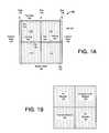
- FIG. 1Ais a simplified illustration of solar panels together with associated frame members assembled into an array and constructed under one or more embodiments of the invention.
- FIG. 1Billustrates an implementation of an embodiment shown by FIG. 1A .
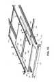
- FIG. 1Cillustrates an assembly for securing a solar module array to an underlying surface, under an embodiment of the invention.
- FIG. 2is a side view of array 100 , as mounted on an underlying surface 210 , according to one or more embodiments of the invention.
- FIG. 3illustrates path flows of water from rain flow, when array is mounted to an inclined surface, under an embodiment of the invention.
- FIG. 4is a top view of a frame assembly formed from a set of frame members and constructed to support a solar panel, according to an embodiment of the invention.
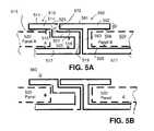
- FIG. 5Ais a side-cross sectional view of a first pair of adjoining interior frame members in an assembly for a solar module array, according to an embodiment of the invention.
- FIG. 5Bis a side-cross sectional view of a second pair of adjoining interior frame members in an assembly for a solar module array, according to an embodiment of the invention.
- FIG. 6is an isometric view of an embodiment such as shown by FIG. 5A and FIG. 5B , without inclusion of solar panels.
- FIG. 7illustrates an alternative embodiment in which an additional component or member is provided to seal or provide flashing between adjoining frame members, according to one or more embodiments of the invention.
- FIG. 8illustrates an alternative embodiment in which a gasket or similar component is fitted or applied into a gap between the horizontal frame members of adjacent solar modules, according to one or more embodiments.
- FIG. 9illustrates an embodiment in which flashing and other structures are used to guide water over the solar modules.
- FIG. 10is a side view of adjacent solar modules having integrated electrical connectivity extending therebetween, under an embodiment of the invention.
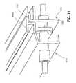
- FIG. 11is an isometric view of an embodiment of FIG. 10 .
- Embodiments described hereinprovide a solar module assembly, and primary support structures for supporting solar modules in an assembly, that prevent or hinder intrusion of water or debris within a gap that is formed by adjacent solar modules.
- An embodimentincludes a frame assembly for a solar module.
- the frame assemblyincludes a plurality of frame members that are structured to collectively support and hold a first solar panel. At least one of the plurality of frame members is structured to adjoin a frame member of a second solar module in forming a joining with the frame member of the second solar module over a length where the frame member of the first and second solar module adjoin.
- a frame assembly for a solar moduleincludes a plurality of frame members that are structured to collectively support and hold a first solar panel.
- the plurality of frame membersincludes a first frame member that provides an overlap frame thickness a distance outward from the first frame member.
- the overlap frame thicknessis extended outward in a lengthwise direction of the first frame member.
- the plurality of frame membersincludes a second frame member that includes a perimeter recessed platform that is extended in a lengthwise direction of the second member, wherein the recessed platform is provided against an exterior surface of the second frame member to define a depth distance between the recessed platform and the exterior surface.
- a solar module assemblyin another embodiment, includes a plurality of solar modules, primary support structures, and a sealing feature.
- the frame assemblyincludes a plurality of frame members, including multiple sets of frame members. Each set of frame members may combine to support a corresponding solar panel in position.
- the plurality of frame membersinclude a pair of adjoining frame members.
- the pair of adjoining frame membersinclude a frame member of a first set of frame members that adjoins a frame member of a second frame member.
- the sealing featureprovided for the pair of adjoining frame members to substantially preclude intrusion of at least one of external air or water into a space underlying a solar module of the first set or of the second set.
- solar modulemeans the combination of a solar collective panel (e.g. photovoltaic laminate containing solar cells, glazed component, or other absorber/generating elements) and frame members that retain the panel.
- a solar modulemay utilize solar energy for any purpose, including generating electricity (i.e. Solar PV) and thermal energy.
- FIG. 1Ais a Simplified Illustration of a Solar Panel Assembly Constructed Under one or more embodiments of the invention.
- an array 100includes a plurality of frame members that assemble to support and hold a collection of solar modules 110 in position over an underlying surface.
- An embodiment of FIG. 1Aillustrates use of four solar modules 110 in a rectangular arrangement, although more or fewer solar modules may be used, and in different configurations.
- the underlying surfacemay correspond to a rooftop or other similar surface. Though not required to be mounted on an inclined surface, one or more embodiments contemplate use of an inclined underlying surface for the mounting of the array of solar modules.
- FIG. 1Amay be described in reference to a vertical and horizontal direction.
- the designation of horizontal and vertical directionsmay be arbitrary, but for purpose of an implementation such as described with FIG. 1A , the vertical direction also coincide with the direction of support structures for the array as a whole.
- the array 100includes rails 135 or other primary support structures that are vertically aligned.
- the frame membersinclude vertical frame members 105 which extend co-linearly with the rails 135 , and horizontal frame members 106 which span between the vertical frame members 105 .
- vertical frame members 105are extended, integrated or coupled with rails 135 or other support structures.
- the rails 135may form a primary securement of the array 100 against an underlying surface.
- the horizontal frame members 106extend between vertical frame members 105 .
- each column of the array 100is separated by a rail 135 , from which one or more vertical frame members 105 are provided.
- adjoining horizontal frame members within a columnare individually or pair-wise structured, or otherwise configured (e.g. through provision of structural or additional features), to form a joining 120 .
- Such adjoining horizontal frame members 106are also interior frame members.
- the joining 120may abut the horizontal frame members 106 in a manner that provides a seal or weather-proofing.
- the array 100may be defined by a perimeter or boundary that includes a top side 102 , a pair of lateral sides 104 , and a bottom side 106 .
- the frame members 105 , 106include or are combined with structures and/or features that seal or weather protect portions of the perimeter to the underlying surface.
- the frame members 105 , 106include and/or are combined with flashing and counter-flash structures that are supported on the underlying surface. Portions of the perimeter that may be sealed include the top side 102 , as well as the lateral sides 104 .
- the perimeter sealingmay form one facet in a design in which water may be directed or moved over or around the solar modules 110 while maintaining weather proofing for the assembly as a whole.
- the watermay result from precipitation, or through the accumulation of water, ice or snow. Additionally, dirt or other unwanted debris may be included in the water.
- horizontal frame members 106 that serve to support adjoining solar modules 110may be constructed or combined so as to create the individual joinings 120 along an edge of each adjoining solar modules 110 .
- the joinings 120 provided by the combination of horizontal frame members 106extending horizontally.
- the joinings 120 in each column of array 100may seal or weatherproof the solar modules 110 against the environment, without need for glazing or glass layers or other additive thicknesses that are applied over the modules or the array 100 as a whole.
- the joinings 120are structural features that create flashing and counter-flashing edges between adjacent interior frames.
- the joiningsinclude or are otherwise provided by additional members and/or features for sealing or flashing. Examples of such additional members and/or features include gaskets, applied sealants such as silicone, or joint members.
- FIG. 1Ashows use of joinings in only one direction (horizontally or spanning between rails 135 )
- one or more variationsprovide for use of joinings 120 of adjacent frame members in both horizontal and vertical directions.
- adjacent columns of array 100may be adjoined and formed from frame members that include features for forming joinings between solar modules of adjacent columns.
- the vertical frame member 105 that supports each columnmay be compressed or otherwise retain each solar module within the larger array so that it is sealed.
- some or all of the vertical frame members 105may coincide in position with a corresponding one of the rails 135 .
- Each rail 135may cause the corresponding vertical frame member to compress the solar module from the edge against the rail 135 , so as to seal that edge of the solar module into the array as a whole.
- one or more embodimentsprovide for one or more of the vertical frame members 105 to use structural or additive features for sealing or weather-guarding individual solar modules in retention.
- joinings 120may provide seals that preclude entrance of water, air, or other elements of the environment. Alternatively, some or all of the joinings 120 may provide flashing by directing fluid without sealing the exterior formed by the solar modules.
- one or more embodimentsprovide for the use of integrated electrical connectors (IEC) 130 , 130 that extend electrical connectivity from one module to another.
- the IEC 130includes electrical connectors embedded or otherwise integrated with vertical frame members 105 and/or horizontal frame members 106 .
- the IEC 130may serve to provide multiple polarities, including ground, and/or carry charge or current produced from any of the solar modules 110 .
- FIG. 1Billustrates an implementation of an embodiment shown by FIG. 1A .
- array 100comprises both solar photovoltaic modules 152 which use solar energy to generate electricity, and thermal modules 154 which use solar energy to generate heat.
- the combinationmay thus enable electricity generation, heating, applications of heating, cooling, and applications of cooling.
- a combinationsuch as shown by an embodiment of FIG. 1B may be combined and used with features and structures described with an embodiment of FIG. 1A .
- a mixed configurationsuch as illustrated by FIG. 1B may be used with any of the embodiments described herein.
- the actual placement and arrangement of solar thermal modules 154 and solar photovoltaic modules 152 within the arraymay vary.
- the IEC 130may serve to connect adjacent photovoltaic modules 152 and pass underneath thermal modules 154 without electrical connectivity.
- Plenums (not shown) for carrying heat or airmay pass underneath thermal modules 154 for effect, while also underlying photovoltaic modules 152 as air is passed or pushed under the array 100 .
- FIG. 1Cillustrates an assembly for securing a solar module array to an underlying surface, under an embodiment of the invention.
- a primary support structure 170includes a plurality of support structure members.
- the support structure membersinclude rails 175 , which secure one or more solar modules 110 to the underlying surface.
- the rails 175may correspond or be equivalent to rails 135 such as shown in FIG. 1A .
- the rails 175may be referenced as aligning vertically, so as to define vertical seams in a solar panel array.
- Each solar panel module 110may include frame members 188 that support and retain individual panels 192 (e.g. PV laminate) from the edge or boundary of the panel.
- frame members 188may extend horizontally between rails 175 and vertically so as to be co-linear with rails.
- the primary support structure 170may be configured to support both incline and flat mountings. With incline mountings, an embodiment of FIG. 1C may be combined with one or more other embodiments described herein to promote or facilitate the movement of water over the solar modules 110 . With flat mountings, an embodiment of FIG. 1C may be combined with other embodiments to inhibit intrusion of water and debris into an interior space between the underlying surface and the solar module array.
- each rail 175includes a base member 180 and a compression member 182 .
- the compression member 182may secure to an edge of a corresponding solar module 110 .
- Bolts 184 or other mechanismsmay be used to compress the member 182 against the base member, thereby securing the corresponding solar module 110 at one edge to the base member 180 .
- the base memberitself may be secured directly or indirectly to the underlying surface.
- struts 190may mount horizontally (to the vertical direction of the rails 175 ) to the underlying surface, and the rails 175 may mount to the struts 190 .
- the solar module arraymay be sealed or weather-proofed at the following locations: (i) between the primary support structure 170 and the underlying surface; (ii) between the vertical frame members 188 and the solar module 110 ; and (iii) between adjacent solar modules in the horizontal direction.
- the rails 175may be provided with flashing and/or a seal to the underlying surface, along a length of the rails 175 .
- a length of the rails 175may correspond to the lateral sides 104 , 104 of the array 100 .
- the primary support structure 170may also include one or more additional perimeter support member 177 that span horizontally between the rails 175 .
- the additional perimeter support member 177may form the top side 102 and may also be flashed or sealed against the underlying surface.
- corner elements 179may be provided that join the spanning perimeter support member 177 and the rails 175 .
- the corner elements 179may also include corner flashing or sealing against the underlying surface.
- U.S. patent application Ser. No. 11/332,000(incorporated by reference herein), for example, provides various techniques for weather-proofing and flashing the primary support structure 170 in a manner described.
- application of the compression member 182 to the base member 180 while gripping or retaining an edge of solar module 110may be used to provide sealing or weather-proofing of the vertical seam formed between the vertical frame member 188 of the solar module 110 and the rail 175 of the primary support structure.
- gaskets or structuresare used to enhance or create a seal or weather-proofing between the primary support structure 170 and the solar module 110 .
- the frame members 188are provided features or structural configurations for effectuating flashing, shingling or sealing. Accordingly, the horizontal frame members 188 (and/or the manner in which the horizontal frame members adjoin one another) may be constructed according to any of the embodiments described below and elsewhere in this application.
- FIG. 1Calso illustrates the passage of electrical connectors 195 from one solar module 120 to another.
- the manner in which the electrical connectors 195 may be combined or integrated with the frame members 188 of the solar modules 120is described below.
- FIG. 2is a side view of array 100 , as mounted on an underlying surface 210 , according to one or more embodiments of the invention.
- Embodiments described hereinenable solar modules 110 to be mounted to either weather-guard or seal interior spaces 220 against intrusions of air, water or other undesirable environmental elements.
- the underlying surface 210is inclined, the manner in which water (e.g. from rain flow) is handled with the presence of a solar array is of concern.
- water flowe.g. from rain
- one or more embodimentsprovide that water flow (e.g. from rain) is directed from the top side 102 downward so as to cascade across the surface of the solar modules 110 .
- Embodimentsallow for the passage of water over the solar modules by including joinings 120 that preclude substantial intrusion of water into the interior space 220 .
- the array 100may be weather-guarded or sealed by a combination of (i) the joining 120 between solar modules 110 , (ii) the force provided by the rails 135 or other support structures through the vertical frame members 105 (which are co-linear with the rails) to effect a seal between them, and (iii) the flashing or sealing of the rails 135 and other perimeter members to the underlying surface,
- FIG. 3illustrates path flows of water from rain flow, when array 100 is mounted to an inclined surface, under an embodiment of the invention.
- one path of water flowis across solar module 110 .
- the joinings 120preclude or inhibit water from entering (substantially or completely) the interior spaces 220 ( FIG. 2 ).
- One or more embodimentsalso facilitate and/or protect water flow around the array 100 .
- vertical frame members 105that are co-linear with lateral sides 104 , 104 of array 100 may be flashed or sealed against the underlying surface 210 to protect water seepage into the perimeter of the underlying space 220 .
- FIG. 4is a top view of a frame assembly formed from a set of frame members and constructed to support a solar panel, according to an embodiment of the invention.
- a frame assembly 400may be rectangular, so as to include frame members that are referenced as horizontal members 412 and vertical members 414 . Reference to a horizontal and vertical direction is arbitrary, but for purpose of an implementation being described, the vertical direction may reflect a direction of water flow as a result of gravity. To this end, the frame assembly 400 may be assumed to be mounted or for mounting on an incline surface, although incline mounting is not necessary.
- vertical members 414are aligned and coupled to support rails 135 ( FIG. 1 ). The rails 135 (see FIG. 1A ) may employ compression to retain the solar modules in place.
- U.S. patent application Ser. No. 11/332,000(which is incorporated by reference herein) describes a rail construction that uses compression to retain a solar module.
- vertical members 414may form a part of the rails and thus compress the solar modules, the vertical members may inherently weather-guard or seal edges where the solar modules are held.
- individual horizontal members 412include one or more sealing features that serve to weather-guard the solar module to solar module transition in the vertical direction.
- the sealing featuresmay include or correspond to a structural feature that is integrated into the frame member 412 .
- each horizontal frame member 412includes one of an overlap frame thickness 422 (e.g. protrusion) or a recess platform 424 for receiving an overlap protrusion.
- frame assembly 400may be configured to position the recess platform 424 adjacent and downhill (in the vertical direction) from an overlap frame thickness of an adjacent frame member that is part of another uphill set of frame members.
- frame assembly 400may be configured to position the overlap frame thickness 422 uphill from a recess platform of an adjacent set of frame members.
- FIG. 5Ais a side-cross sectional view of a first pair of adjoining interior frame members in an assembly for a solar module array, according to an embodiment of the invention.
- the pair of adjoining interior frame membersinclude a first interior frame member 510 and a second interior frame member 560 .
- second interior frame member 560When mounted on an incline, second interior frame member 560 is uphill from the first interior frame member 510 , as shown by an Arrow A.
- Each interior frame member 510 , 560is structured to hold and support a corresponding solar collective panel 520 .
- the panel 520may correspond to, for example, laminate for photovoltaic panels, or a glazing element for thermal modules.
- the various members of the first interior frame member 510form an opening 515 that receives the corresponding solar panel 520 .
- the opening 515may be formed by an underside 513 of an exterior segment 514 , as positioned over a base segment 517 .
- a first height segment 519may extend from base segment 517 partially towards exterior segment 514 .
- the first wall (or height segment) 519may join a platform segment 521 , which may extend parallel or substantially parallel to the base segment 517 .
- a second wall 523may extend from the platform segment 521 to the exterior segment 514 .
- the space defined by the distance between the platform segment 521 and the base segment 517may define an opening 518 which is smaller than a dimension of the cross section of the solar panels 520 .
- the opening 518serves as a buffer space to enable the use of a recess platform surface 525 of the platform segment 521 to receive an extension member from the second interior frame member.
- each interior frame member 510 , 560may extend to and couple to other orthogonally aligned frame members (See FIG. 4 ), and therefore leverage support from one of the corresponding rails 135 to support the solar module.
- a depth distance (d 1 ) of the recess platform surface 525may be measured as corresponding to a height of the second wall 523 (and a distance to an exterior surface 511 provided by the exterior segment 514 ).
- the depth distance d 1may be greater than or substantially equivalent to a thickness dimension of an extension provided by the second interior frame segment 560 .
- the second interior frame member 560includes an opening 568 having an extended exterior segment 562 , a wall segment 563 , and a base segment 565 .
- a space between the base segment 565 and the extended segment member 562defines the opening 568 where the corresponding solar panel 520 is received and supported.
- the wall segment 563extends sufficiently from the base segment 565 so that the extended exterior segment 562 is positioned above the raised platform surface 535 of the adjacent first interior frame segment 510 .
- a thickness (d 2 ) of the extended exterior segment 562is dimensioned to be less than the depth distance (d 1 ) provided by the recess platform surface 525 . In this way, the extended exterior segment 562 may be accommodated over the recessed platform surface 525 .
- the dimension of the depth distance (d 1 ) and the thickness (d 2 ) of the extended exterior segment 562may be such that the exterior surface 511 of the exterior segment 514 of the first interior frame member 510 is substantially flush with the exterior surface 561 of the extended exterior segment 562 of the second interior frame member 560 .
- the combination of the first and second horizontal frame membersresult in a shingle-like or flashing effect in which water is passed over the exterior of the combined structure (with solar modules).
- Watermay pass downhill (as shown by directional Arrow A).
- watermay pass from the second solar module 520 to the first solar module, and any water that falls in a gap 575 formed by the joining of the first and second horizontal frame members will not be inclined to travel uphill on the recessed platform surface 525 .
- An interior space 577may thus be substantially protected from intrusion of water, even when water cascades over the combined surfaces formed by the solar panels 520 and frame members.
- FIG. 5Bis a side-cross sectional view of a second pair of adjoining interior frame members in an assembly for a solar module array, according to an embodiment of the invention.
- FIG. 5Bmay substantially duplicate an embodiment such as shown by FIG. 5A , but illustrate a point that the frame assembly of any one solar panel 520 may include both the recessed platform surface 525 and the extended exterior segment 562 which provides a thickness that is received on a recessed platform surface on the frame assembly of a neighboring solar panel.
- the solar panel (“B”) of the second interior frame memberis shown having the receiving platform surface 525 (as shown and described with FIG. 5A for the first interior frame member 510 ).
- any given solar panel 520may include the recess platform surface 525 on one frame member that is uphill on an inclined array, and the extended exterior segment 562 at the other diametric frame member positioned downhill on the inclined array.
- FIG. 6is an isometric view of an embodiment such as shown by FIG. 5A and FIG. 5B , without inclusion of solar panels 520 .
- the interior frame members 510 , 560may form a joining through structures formed on each respective frame member.
- the first frame 510includes an exterior segment 514 , base segment 517 , first wall 519 which raises to platform segment 521 .
- the recessed platform surface 525may be formed on the platform segment 521 .
- the second wall 523may extend form the recessed platform surface 525 to the exterior segment 514 .
- the second interior frame member 560includes extended exterior segment 562 that overlaps onto the recessed platform surface 525 .
- the opening 568( FIG. 5A ) may be defined by a portion of the extended exterior segment 562 and the base 565 .
- the extended exterior segment 562 of the second interior segment 560provides one form of an overlap frame thickness from which a shingle or flashing affect may be provided.
- gaskets or other materialsmay be used to further seal the joining formed with the overlap frame thickness. With loose fitting, some water may enter the gap 575 (see FIG. 5A ), but the water may be precluded or inhibited from traveling across recessed platform surface 525 , particularly when an incline mount is used. With tight fitting, gaskets or other structures, seal may be formed that substantially precludes water from entering the sealed portion within the gap 575 even when the arrays are mounted level instead of on an inclined surface.
- FIG. 7illustrates an alternative embodiment in which an additional component or member is provided to seal or provide flashing between adjoining frame members, according to one or more embodiments of the invention.
- an embodiment of FIG. 7provides for use of a gap member 710 that extends between rail members or other supports (not shown in FIG. 7 ) that support adjacent solar modules.
- the gap membermay include a T-shape cross section, so that a length of the member fits within a gap formed by adjacent horizontal frame members.
- the surfaces of adjoining interior membersmay be relatively smooth to receive and retain a length segment 712 of gap member 710 .
- a flange 714may extend between the pair of adjacent interior members to block the entrance of water into the gap 720 . Additional weatherproofing may be achieved by placing a gasket between segment 712 or flange 714 and the mating frame members
- FIG. 8illustrates an alternative embodiment in which a gasket or similar component is fitted or applied into a gap between the horizontal frame members of adjacent solar modules, according to one or more embodiments.
- the surfaces of adjoining interior membersmay be relatively smooth to form a gap 820 .
- the gap 820may receive a gasket component 810 , filler or other form of deformable material. The effect is to seal the gap 820 , thereby enabling water to pass from one solar module to another without entering an interior space of the array beneath the solar modules.
- the gasket component 810may flange or spread over adjoining frame members to provide a seal.
- solar module arraysare often mounted on inclines.
- rain water and precipitationcan collect on a top surface.
- a perimeter flashing or seal(such as described in U.S. patent application Ser. No. 11/332,000) may be used to preclude or inhibit rain water from entering the interior of the solar module array from a perimeter surface. But water may pool at the top end of the array, and on structures such as rooftops, the pooling may have undesirable consequences.
- the effects of poolingmay be mitigated or even eliminated by enabling water to cascade downhill over the array of solar modules.
- watermay flow along a directional arrow B.
- embodimentssuch as described with FIG. 4-7 .
- flashing or sealing between frame members that support solar panel modulesenables the water to pass over the adjoining solar modules without intrusion of water into the interior space of the array beneath the solar module.
- FIG. 9illustrates an embodiment in which flashing and other structures are used to guide water over the solar modules.
- a flashing component 930may be installed under a roof covering 905 and extended to overlay the solar module array 900 . This results in water running down the roof to be conveyed from the roof covering 905 up onto the array 900 .
- the flashing componentmay include two sections (i.e. flashing and counter-flashing).
- flashing component 930One benefit provided by flashing component 930 is that it eliminates the pooling of water, snow, ice, or other debris behind (i.e. adjacent top side 102 ) the solar module array 900 .
- One or more embodimentsprovide interlocking solar modules that electrically connect during the assembly of individual modules into the racking structure for a given solar array. Such embodiments may eliminate a secondary step of having to hand-connect the wiring (both module potential and grounding) after the modules are physically placed
- the electrical connectorsare embedded in the frames of the modules, such that when two modules are slid together during assembly, the electrical interconnections between adjacent modules are simultaneously formed.
- FIG. 1Aillustrates one alignment of electrical wiring or lines for an array of solar modules.
- the electrical linemay extend in a direction of the rail 135 or other support structure.
- each solar moduleincludes electrical connectors for extending electrical connectivity to an adjacent solar panel.
- FIG. 10is a side view of adjacent solar modules having integrated electrical connectivity extending therebetween, under an embodiment of the invention.
- a first solar module 1010may include a panel 1012 and a frame member 1014 .
- a second solar module 1060may include a panel 1062 and a frame member 1064 .
- Each of the solar modules 1010 and 1060may include a respective integrated electrical connector 1020 , 1070 .
- the electrical connectors 1020 , 1070may provide respective electrical leads or wiring.
- the connectors 1020 , 1070(as well as conduits for the leads) are integrated through holes 1015 , 1065 formed in the respective frame members 1014 , 1064 .
- the connectors 1020 , 1070may each be secured by a locking nut on the opposite side of the respective frame member 1014 , 1064 to hold them captive. In alternate configurations, the connectors may be press fit, snapped, or otherwise secured into the module frames or the solar panels themselves.
- FIG. 11is an isometric view of an embodiment of FIG. 10 , illustrating use of the integrated electrical connectors 1020 , 1070 (not visible in FIG. 11 ) formed in frame members 1014 , 1064 .
- Each frame member 1014 , 1064may include an inward extension 1034 , 1064 in which the holes 1015 , 1065 may be formed for receiving and retaining the respective electrical connectors 1020 , 1070 .
- An embodiment such as shown and described with FIG. 10 and FIG. 11may incorporate features or components of other embodiments described herein.
- the electrical connectors 1020 , 1070may be integrated into frame members 1014 , 1064 that include structures of an overlap frame thickness 1080 and a recessed platform 1090 for receiving the overlap thickness.
- overlap frame thickness 1080 and recessed platform 1090may seal or hinder intrusion of water or other environmental factors.
- FIG. 10 and FIG. 11assumes that the connections are made during lateral assembly of the modules
- alternate configurationsare possible.
- One such configurationmay have the connectors oriented in a vertical arrangement requiring the modules to be laid in from a vertical direction on their common edge as opposed to laterally sliding the modules together.
- connectorsare oriented to line up with connectors on adjoining modules so that lower modules connect to modules above them.
Landscapes
- Engineering & Computer Science (AREA)
- Chemical & Material Sciences (AREA)
- Mechanical Engineering (AREA)
- Sustainable Development (AREA)
- Sustainable Energy (AREA)
- Thermal Sciences (AREA)
- Physics & Mathematics (AREA)
- Combustion & Propulsion (AREA)
- Life Sciences & Earth Sciences (AREA)
- General Engineering & Computer Science (AREA)
- Architecture (AREA)
- Civil Engineering (AREA)
- Structural Engineering (AREA)
- Photovoltaic Devices (AREA)
- Roof Covering Using Slabs Or Stiff Sheets (AREA)
Abstract
Description
Claims (28)
Priority Applications (2)
| Application Number | Priority Date | Filing Date | Title |
|---|---|---|---|
| US11/750,948US7900407B2 (en) | 2004-02-13 | 2007-05-18 | Interconnected solar module design and system |
| US13/042,266US8656659B2 (en) | 2004-02-13 | 2011-03-07 | Interconnected solar module design and system |
Applications Claiming Priority (7)
| Application Number | Priority Date | Filing Date | Title |
|---|---|---|---|
| US54475304P | 2004-02-13 | 2004-02-13 | |
| US10/855,254US8344239B2 (en) | 2004-02-13 | 2004-05-26 | Mechanism for mounting solar modules |
| US64361905P | 2005-01-13 | 2005-01-13 | |
| US11/332,000US7856769B2 (en) | 2004-02-13 | 2006-01-13 | Rack assembly for mounting solar modules |
| US74759306P | 2006-05-18 | 2006-05-18 | |
| US82474406P | 2006-09-06 | 2006-09-06 | |
| US11/750,948US7900407B2 (en) | 2004-02-13 | 2007-05-18 | Interconnected solar module design and system |
Related Parent Applications (2)
| Application Number | Title | Priority Date | Filing Date |
|---|---|---|---|
| US10/855,254Continuation-In-PartUS8344239B2 (en) | 2004-02-13 | 2004-05-26 | Mechanism for mounting solar modules |
| US11/332,000Continuation-In-PartUS7856769B2 (en) | 2004-02-13 | 2006-01-13 | Rack assembly for mounting solar modules |
Related Child Applications (1)
| Application Number | Title | Priority Date | Filing Date |
|---|---|---|---|
| US13/042,266ContinuationUS8656659B2 (en) | 2004-02-13 | 2011-03-07 | Interconnected solar module design and system |
Publications (2)
| Publication Number | Publication Date |
|---|---|
| US20070251567A1 US20070251567A1 (en) | 2007-11-01 |
| US7900407B2true US7900407B2 (en) | 2011-03-08 |
Family
ID=38724051
Family Applications (2)
| Application Number | Title | Priority Date | Filing Date |
|---|---|---|---|
| US11/750,948Expired - Fee RelatedUS7900407B2 (en) | 2004-02-13 | 2007-05-18 | Interconnected solar module design and system |
| US13/042,266Expired - Fee RelatedUS8656659B2 (en) | 2004-02-13 | 2011-03-07 | Interconnected solar module design and system |
Family Applications After (1)
| Application Number | Title | Priority Date | Filing Date |
|---|---|---|---|
| US13/042,266Expired - Fee RelatedUS8656659B2 (en) | 2004-02-13 | 2011-03-07 | Interconnected solar module design and system |
Country Status (4)
| Country | Link |
|---|---|
| US (2) | US7900407B2 (en) |
| EP (1) | EP2033239A4 (en) |
| CA (1) | CA2654764C (en) |
| WO (1) | WO2007137199A2 (en) |
Cited By (29)
| Publication number | Priority date | Publication date | Assignee | Title |
|---|---|---|---|---|
| US20090025708A1 (en)* | 2007-07-24 | 2009-01-29 | Sunpower Corporation | Rolling Motion Tracking Solar Assembly |
| US20100162641A1 (en)* | 2007-04-20 | 2010-07-01 | Arcelormittal - Stainless And Nickel Alloys | Bearing frame for a panel such as a photoelectric panel and building external wall including such frames |
| US20100288338A1 (en)* | 2008-01-08 | 2010-11-18 | Daiki Yamamoto | Solar cell module |
| US20100313928A1 (en)* | 2009-06-11 | 2010-12-16 | Rose Douglas H | Photovoltaic Array With Array-Roof Integration Member |
| US20110138711A1 (en)* | 2009-12-11 | 2011-06-16 | Grenzone Pte Ltd. | Integrated Photovoltaic Roof Assembly |
| US20110138710A1 (en)* | 2009-07-02 | 2011-06-16 | E. I. Du Pont De Nemours And Company | Building-integrated solar-panel roof element systems |
| US20110209745A1 (en)* | 2010-02-26 | 2011-09-01 | General Electric Company | Photovoltaic framed module array mount utilizing asymmetric rail |
| US20110239546A1 (en)* | 2010-04-01 | 2011-10-06 | Yanegijutsukenkyujo Co., Ltd. | Installation structure of solar cell module |
| US20120023726A1 (en)* | 2010-07-29 | 2012-02-02 | John Bellacicco | Method and apparatus providing simplified installation of a plurality of solar panels |
| US20120096781A1 (en)* | 2010-10-20 | 2012-04-26 | Bruce Romesburg | Structural Insulated Monolithic Photovoltaic Solar-Power Roof and Method of Use Thereof |
| US20130335877A1 (en)* | 2011-03-11 | 2013-12-19 | Mobasolar Sas | Separate connection device for grounding electrical equipment comprising a plurality for separate electrical components |
| US20140150251A1 (en)* | 2011-03-15 | 2014-06-05 | Richard William Erickson | Unitized photovoltaic assembly |
| US8782972B2 (en) | 2011-07-14 | 2014-07-22 | Owens Corning Intellectual Capital, Llc | Solar roofing system |
| US8806816B2 (en)* | 2008-09-03 | 2014-08-19 | Sapa Extrusions, Inc. | Solar module frames having water drain |
| US8875453B2 (en) | 2012-06-15 | 2014-11-04 | Kanzo, Inc. | System for mounting solar modules |
| US9273885B2 (en) | 2013-06-13 | 2016-03-01 | Building Materials Investment Corporation | Roof integrated photovoltaic system |
| US9416992B2 (en) | 2014-02-28 | 2016-08-16 | Sunpower Corporation | End clamps for solar systems |
| US9531319B2 (en) | 2013-12-23 | 2016-12-27 | Sunpower Corporation | Clamps for solar systems |
| US9813015B1 (en) | 2016-06-29 | 2017-11-07 | Sunpower Corporation | End clamp for mounting solar module to rail |
| USD831861S1 (en)* | 2016-02-04 | 2018-10-23 | Solar Century Holdings Limited | Rooftop frame |
| US10256765B2 (en) | 2013-06-13 | 2019-04-09 | Building Materials Investment Corporation | Roof integrated photovoltaic system |
| US10490682B2 (en) | 2018-03-14 | 2019-11-26 | National Mechanical Group Corp. | Frame-less encapsulated photo-voltaic solar panel supporting solar cell modules encapsulated within multiple layers of optically-transparent epoxy-resin materials |
| US11050383B2 (en) | 2019-05-21 | 2021-06-29 | Nextracker Inc | Radial cam helix with 0 degree stow for solar tracker |
| US20210265938A1 (en)* | 2018-07-04 | 2021-08-26 | Sabic Global Technologies B.V. | Solar roof forming element, building, and method of forming a roof |
| US11159120B2 (en) | 2018-03-23 | 2021-10-26 | Nextracker Inc. | Multiple actuator system for solar tracker |
| US11387771B2 (en) | 2018-06-07 | 2022-07-12 | Nextracker Llc | Helical actuator system for solar tracker |
| US11834835B2 (en) | 2020-03-30 | 2023-12-05 | Bmic Llc | Interlocking laminated structural roofing panels |
| US11855580B2 (en) | 2020-11-09 | 2023-12-26 | Bmic Llc | Interlocking structural roofing panels with integrated solar panels |
| US12368404B2 (en) | 2023-01-18 | 2025-07-22 | Imam Abdulrahman Bin Faisal University | Dual-function racking structure for natural cooling of photovoltaic panels |
Families Citing this family (46)
| Publication number | Priority date | Publication date | Assignee | Title |
|---|---|---|---|---|
| US7900407B2 (en)* | 2004-02-13 | 2011-03-08 | Pvt Solar, Inc. | Interconnected solar module design and system |
| US7856769B2 (en) | 2004-02-13 | 2010-12-28 | Pvt Solar, Inc. | Rack assembly for mounting solar modules |
| US8344239B2 (en)* | 2004-02-13 | 2013-01-01 | Pvt Solar, Inc. | Mechanism for mounting solar modules |
| US20090038668A1 (en)* | 2007-08-08 | 2009-02-12 | Joshua Reed Plaisted | Topologies, systems and methods for control of solar energy supply systems |
| WO2008028151A2 (en)* | 2006-08-31 | 2008-03-06 | Pvt Solar, Inc. | Technique for electrically bonding solar modules and mounting assemblies |
| US7721492B2 (en)* | 2006-09-06 | 2010-05-25 | Pvt Solar, Inc. | Strut runner member and assembly using same for mounting arrays on rooftops and other structures |
| US7857269B2 (en)* | 2006-11-29 | 2010-12-28 | Pvt Solar, Inc. | Mounting assembly for arrays and other surface-mounted equipment |
| US20090230265A1 (en) | 2008-03-17 | 2009-09-17 | Michael Newman | Mounting System for Photovoltaic Panels |
| US20100089434A1 (en)* | 2008-10-11 | 2010-04-15 | Fishman Oleg S | Efficient Air-Cooled Solar Photovoltaic Modules and Collectors for High Power Applications |
| EP2187146B1 (en)* | 2008-11-14 | 2019-01-02 | Böcherer, Hans | Support assembly |
| US9103563B1 (en) | 2008-12-30 | 2015-08-11 | Sunedison, Inc. | Integrated thermal module and back plate structure and related methods |
| US20100180933A1 (en)* | 2009-01-19 | 2010-07-22 | Jac Products, Inc. | Grounding system and method for use with solar panel modules |
| US8240109B2 (en)* | 2009-03-20 | 2012-08-14 | Northern States Metals Company | Support system for solar panels |
| US8316590B2 (en) | 2009-03-20 | 2012-11-27 | Northern States Metals Company | Support system for solar panels |
| US20110220596A1 (en)* | 2009-03-20 | 2011-09-15 | Northern States Metals Company | Support system for solar panels |
| US8256169B2 (en) | 2009-03-20 | 2012-09-04 | Northern States Metals Company | Support system for solar panels |
| US8316592B2 (en)* | 2009-03-21 | 2012-11-27 | Carlo John Lanza | Protective covering for roof mounted systems |
| US8869470B2 (en) | 2009-03-21 | 2014-10-28 | Carlo John Lanza | Protective covering for roof device |
| US8413944B2 (en)* | 2009-05-01 | 2013-04-09 | Applied Energy Technologies | Mounting systems for solar panels |
| WO2010144637A1 (en)* | 2009-06-10 | 2010-12-16 | Solar Infra, Inc. | Integrated solar photovoltaic ac module |
| US20110209742A1 (en)* | 2009-06-10 | 2011-09-01 | Pvt Solar, Inc. | Method and Structure for a Cool Roof by Using a Plenum Structure |
| US20110005512A1 (en)* | 2009-07-10 | 2011-01-13 | Ruesswick Scott | Adjustable solar panel support structure |
| WO2011038001A1 (en)* | 2009-09-22 | 2011-03-31 | Stellaris Corporation | Integrated mount for solar panels |
| US8215071B2 (en)* | 2010-02-02 | 2012-07-10 | Sunpower Corporation | Integrated composition shingle PV system |
| US20110138599A1 (en)* | 2010-07-29 | 2011-06-16 | John Bellacicco | Mounting system supporting slidable installation of a plurality of solar panels as a unit |
| US20120111393A1 (en)* | 2010-07-29 | 2012-05-10 | Joshua Conley | Integrated cartridge for adhesive-mounted photovoltaic modules |
| DE102010040124A1 (en)* | 2010-09-01 | 2012-03-01 | Mounting Systems Gmbh | Profile rail, holding element and thus formed solar module assembly, in particular for a transverse mounting of solar modules |
| US8701361B2 (en) | 2011-01-12 | 2014-04-22 | Pierino Ferrara | Rooftop system with integrated photovoltaic modules and method for constructing the same |
| US9422957B2 (en) | 2011-02-01 | 2016-08-23 | Thomas & Betts International Llc | Panel clamp |
| US8839573B2 (en) | 2011-02-11 | 2014-09-23 | Northern States Metals Company | Spring clip |
| US10041693B2 (en)* | 2011-03-30 | 2018-08-07 | Daniel Joseph Rheaume | Solar-powered ridge vent fan unit |
| FR2976007A1 (en)* | 2011-05-31 | 2012-12-07 | All Star Corp Ltd | MODULAR COVER DEVICE |
| EP2530404A3 (en)* | 2011-05-31 | 2014-06-11 | All Star Corporation Limited | Modular cover |
| WO2014006630A1 (en)* | 2012-07-05 | 2014-01-09 | Dow Global Technologies Llc | Flexible building integrated pv device |
| WO2014120272A1 (en)* | 2013-02-04 | 2014-08-07 | Dynoraxx, Inc. | Solar panel grounding system and clip |
| US9303663B2 (en) | 2013-04-11 | 2016-04-05 | Northern States Metals Company | Locking rail alignment system |
| US10432132B2 (en) | 2013-07-01 | 2019-10-01 | RBI Solar, Inc. | Solar mounting system having automatic grounding and associated methods |
| US9231518B2 (en) | 2013-10-21 | 2016-01-05 | Spice Solar, Inc. | Solar panel mechanical connector and frame |
| US9923511B2 (en)* | 2015-08-03 | 2018-03-20 | Jason Sen Xie | Connecting solar modules |
| US10505492B2 (en) | 2016-02-12 | 2019-12-10 | Solarcity Corporation | Building integrated photovoltaic roofing assemblies and associated systems and methods |
| KR102072577B1 (en)* | 2017-12-07 | 2020-02-03 | 엘지이노텍 주식회사 | Thermoelectric device module |
| US11402058B2 (en)* | 2019-05-14 | 2022-08-02 | Field Energy Ops, Inc. | Boltless module support structures and boltless module attachment method |
| NL2023965B1 (en)* | 2019-06-21 | 2021-01-25 | Energy Team B V | SOLAR PANEL ASSEMBLY, SET OF AT LEAST ONE SOLAR PANEL ASSEMBLY AND SOME MOUNTING ELEMENTS, ROOF TO WHICH SUCH A SET IS FITTED, AND PROCEDURE FOR MOUNTING SOLAR PANELS ON A ROOF |
| EP3997393A1 (en)* | 2019-06-21 | 2022-05-18 | Energy Team B.V. | Self-supporting solar panel assembly, set of at least one self- supporting solar panel assembly and a plurality of fastening elements, roof on which such a set is arranged, and method for mounting solar panels on a roof |
| US12088238B1 (en) | 2019-09-23 | 2024-09-10 | Terrasmart, Inc. | Solar panel tracker systems and methods |
| KR102413135B1 (en)* | 2021-12-29 | 2022-06-24 | (주)디케이에너지 | Bracket for fixing the solar module |
Citations (79)
| Publication number | Priority date | Publication date | Assignee | Title |
|---|---|---|---|---|
| US1159372A (en) | 1915-11-09 | Charles W Goff | Shingling-bracket. | |
| US1306434A (en) | 1919-06-10 | Philip p | ||
| US2747166A (en) | 1954-12-13 | 1956-05-22 | Collins Radio Co | Interlocked flexible contact assembly for shaft |
| US3881799A (en) | 1972-09-11 | 1975-05-06 | George H Elliott | Resilient multi-micro point metallic junction |
| US4029080A (en) | 1975-01-27 | 1977-06-14 | Westinghouse Electric Corporation | Thermal collector of solar energy adapted for high temperature operation |
| US4061413A (en) | 1974-10-10 | 1977-12-06 | Siemens Aktiengesellschaft | Gasket for the high-frequency-tight connection of detachable metallic shielding elements |
| US4150660A (en) | 1977-09-15 | 1979-04-24 | Margot Elizabeth Peters | Easy access energy conversion panels for solar heating systems |
| US4239555A (en) | 1979-07-30 | 1980-12-16 | Mobil Tyco Solar Energy Corporation | Encapsulated solar cell array |
| US4336413A (en) | 1979-09-10 | 1982-06-22 | R.T.C. La Radiotechnique Compelec | Solar panels |
| US4372292A (en) | 1981-04-14 | 1983-02-08 | Ort Sterling L | Method and apparatus for construction of a solar collector |
| US4636577A (en) | 1983-08-29 | 1987-01-13 | Thomas & Betts Corporation | Solar panel module and support therefor |
| US4936063A (en) | 1989-05-19 | 1990-06-26 | Humphrey John B | Frame flanges for mounting photovoltaic modules direct to roof structural framing |
| US4961712A (en) | 1988-10-20 | 1990-10-09 | Schroff Gmbh | Mechanical and electrical connection between an extruded metal profile and a cast metal member |
| US4993959A (en) | 1990-01-19 | 1991-02-19 | Amp Incorporated | Grounding clip |
| EP0417303A1 (en) | 1989-03-30 | 1991-03-20 | Hirai Engineering Corporation | Roof collecting solar energy |
| US5180442A (en) | 1992-04-06 | 1993-01-19 | Eric Elias | Integration system for solar modules |
| EP0587348A2 (en) | 1992-09-07 | 1994-03-16 | Hirai Engineering Corporation | Roof apparatus |
| EP0599497A1 (en) | 1992-11-19 | 1994-06-01 | Hirai Engineering Corporation | Roof system utilizing a solar cell |
| US5338369A (en) | 1993-02-16 | 1994-08-16 | Rawlings Lyle K | Roof-integratable photovolatic modules |
| EP0614058A2 (en) | 1993-03-04 | 1994-09-07 | C.M.E. Schwarz Holdinggesellschaft M.B.H. | Device for collecting heat energy |
| US5409549A (en) | 1992-09-03 | 1995-04-25 | Canon Kabushiki Kaisha | Solar cell module panel |
| US5451167A (en) | 1994-07-28 | 1995-09-19 | Illinois Tool Works Inc. | Grounding clip |
| US5524401A (en) | 1993-01-12 | 1996-06-11 | Misawa Homes Co., Ltd. | Roof with solar battery |
| US5571338A (en) | 1993-11-26 | 1996-11-05 | Sanyo Electric Co., Ltd. | Photovoltaic module and a photovoltaic apparatus |
| US5603187A (en) | 1995-07-05 | 1997-02-18 | Merrin; William R. | Watertight system for mounting equipment on roof |
| JPH09184209A (en) | 1996-01-08 | 1997-07-15 | Sekisui Chem Co Ltd | Solar system house |
| US5687453A (en) | 1995-04-17 | 1997-11-18 | Chrysler Corporation | Grounding washer and arrangements for conductive hinge joints |
| US5740996A (en) | 1995-08-09 | 1998-04-21 | Genschorek; Gido | Device for mounting plate-like construction components |
| JPH10159201A (en) | 1996-12-03 | 1998-06-16 | Sekisui Chem Co Ltd | Ventilation structure behind solar cell module juxtaposition body and ventilation structure of building provided with the structure |
| US5788204A (en) | 1996-09-26 | 1998-08-04 | Goodwin; Jeffrey G | Pump jack base |
| US5851309A (en) | 1996-04-26 | 1998-12-22 | Kousa; Paavo | Directing and concentrating solar energy collectors |
| EP0905795A2 (en) | 1997-09-24 | 1999-03-31 | Matsushita Electric Works, Ltd. | Mounting system for installing an array of solar battery modules of a panel-like configuration on a roof |
| JPH11186586A (en) | 1997-12-22 | 1999-07-09 | Canon Inc | Panel fixing member, ground structure of solar cell panel, and grounding method thereof |
| US5924486A (en) | 1997-10-29 | 1999-07-20 | Tecom, Inc. | Environmental condition control and energy management system and method |
| JPH11204819A (en) | 1998-01-07 | 1999-07-30 | Canon Inc | Solar power generator |
| DE19804685A1 (en) | 1998-02-06 | 1999-08-12 | Schaefer Wolfgang | Energy generating solar cell |
| US5986203A (en) | 1996-06-27 | 1999-11-16 | Evergreen Solar, Inc. | Solar cell roof tile and method of forming same |
| JP2000100490A (en) | 1998-09-24 | 2000-04-07 | Matsushita Electric Works Ltd | Grounding structure for solar battery module |
| US6106310A (en) | 1997-11-19 | 2000-08-22 | The Whitaker Corporation | Panel-grounding contact |
| US6195066B1 (en) | 1999-01-19 | 2001-02-27 | Thomas C. Pegues, Jr. | Satellite dish mounting arm |
| US6201179B1 (en) | 1997-10-03 | 2001-03-13 | Nick Dalacu | Array of photovoltaic modules for an integrated solar power collector system |
| US6269596B1 (en) | 1997-02-05 | 2001-08-07 | Canon Kabushiki Kaisha | Roof member and mounting method thereof |
| JP2001214579A (en) | 2000-01-31 | 2001-08-10 | Sanko Metal Ind Co Ltd | Earth structure in flat solar enclosure |
| US6283770B1 (en) | 1998-12-11 | 2001-09-04 | Cisco Technology, Incc. | Minimal intrusion EMI shielding clip to maintain electrical contact between two parallel surfaces |
| JP2001262800A (en) | 2000-03-15 | 2001-09-26 | Kanegafuchi Chem Ind Co Ltd | Photovoltaic power generation device |
| US6320120B1 (en) | 1999-04-15 | 2001-11-20 | Laird Technologies | Low profile clip-on shielding strip |
| US6323478B1 (en) | 1997-10-30 | 2001-11-27 | Canon Kabushiki Kaisha | Photovoltaic power generation roof and installation method thereof |
| US6366304B1 (en) | 1999-10-04 | 2002-04-02 | Fujitsu Limited | Thermal correction for image-forming exposure device and method of manufacturing the device |
| WO2002041407A1 (en) | 2000-11-16 | 2002-05-23 | Kaneka Corporation | Solar battery module, photovoltaic power generation system, support block supporting solar battery module, and photovoltaic power generation system installation method |
| US20020078991A1 (en)* | 2000-10-31 | 2002-06-27 | Yoshitaka Nagao | Solar battery, solar generating apparatus, and building |
| US6465724B1 (en) | 1998-07-28 | 2002-10-15 | Bp Solar International Llc | Photovoltaic module framing system with integral electrical raceways |
| US20030010372A1 (en) | 2001-07-10 | 2003-01-16 | Powerlight Corporation | Multi-position photovoltaic assembly |
| US20030015637A1 (en) | 2001-07-20 | 2003-01-23 | Liebendorfer John E. | Apparatus and method for positioning a module on an object |
| US6521821B2 (en) | 1997-12-27 | 2003-02-18 | Canon Kabushiki Kaisha | Fixing member, a solar cell module array using said fixing member, and a method for installing a solar cell module or a roofing member using said fixing member |
| US20030071177A1 (en) | 2001-10-16 | 2003-04-17 | Aussiker Glen Alan | Cable tray stand |
| US20030094193A1 (en) | 2001-11-16 | 2003-05-22 | First Solar, Llc | Photovoltaic array |
| US20040011354A1 (en) | 2000-04-04 | 2004-01-22 | Erling Peter Stuart | Framing system for solar panels |
| US20040163338A1 (en) | 2003-02-26 | 2004-08-26 | Unirac, Inc., A New Mexico Corporation | Low profile mounting system |
| JP2004251037A (en) | 2003-02-21 | 2004-09-09 | Kyocera Corp | Roof fixing device and fixing structure using the same |
| JP2005194771A (en) | 2004-01-07 | 2005-07-21 | Aaki Yamade Kk | Solar battery module mounting structure |
| US20050161074A1 (en) | 2003-12-16 | 2005-07-28 | Paul Garvison | Photovoltaic module mounting unit and system |
| US20050257453A1 (en)* | 2004-05-18 | 2005-11-24 | Barry Cinnamon | Mounting system for a solar panel |
| US20060032527A1 (en) | 2004-07-27 | 2006-02-16 | Spheral Solar Power Inc. | Solar panel overlay and solar panel overlay assembly |
| US20060042682A1 (en) | 2004-09-02 | 2006-03-02 | Icp Solar Technologies Inc. | Photovoltaic building elements |
| US20060086382A1 (en) | 2004-02-13 | 2006-04-27 | Plaisted Joshua R | Mechanism for mounting solar modules |
| US20060118163A1 (en) | 2004-02-13 | 2006-06-08 | Kineo Design Group, Llc | Rack assembly for mounting solar modules |
| US20060124167A1 (en) | 2004-12-15 | 2006-06-15 | Xuejun Fan | Thermal-efficient power converter enclosure for solar panels |
| JP2007262764A (en) | 2006-03-29 | 2007-10-11 | Yane Gijutsu Kenkyusho:Kk | Grounding structure and ground fixing bracket of solar battery module |
| US7293748B1 (en) | 2005-11-21 | 2007-11-13 | Hoser Kevin R | Paint can support apparatus and method |
| US20070295391A1 (en) | 2006-03-09 | 2007-12-27 | Sunpower Corporation | PV Module Mounting and Support Assembly and Installation |
| EP1873843A2 (en) | 2006-06-26 | 2008-01-02 | Fototherm S.r.l. | Photovoltaic plant |
| US20080053009A1 (en) | 2006-09-06 | 2008-03-06 | Joshua Reed Plaisted | Strut runner member and assembly using same for mounting arrays on rooftops and other structures |
| US20080053517A1 (en) | 2006-08-31 | 2008-03-06 | Joshua Reed Plaisted | Technique for electrically bonding solar modules and mounting assemblies |
| US20080121273A1 (en) | 2006-11-29 | 2008-05-29 | Joshua Reed Plaisted | Mounting assembly for arrays and other surface-mounted equipment |
| US20080169018A1 (en) | 2004-08-12 | 2008-07-17 | Mitsubishi Denki Kabushiki Kaisha | Solar Cell Unit Attaching Apparatus |
| US7419377B1 (en) | 2007-08-20 | 2008-09-02 | Solaria Corporation | Electrical coupling device and method for solar cells |
| US7469508B2 (en) | 2003-12-23 | 2008-12-30 | Isolpack S.P.A. | Insulating panel and photovoltaic module for building purposes |
| US20090038668A1 (en) | 2007-08-08 | 2009-02-12 | Joshua Reed Plaisted | Topologies, systems and methods for control of solar energy supply systems |
| US7592537B1 (en)* | 2004-02-05 | 2009-09-22 | John Raymond West | Method and apparatus for mounting photovoltaic modules |
Family Cites Families (11)
| Publication number | Priority date | Publication date | Assignee | Title |
|---|---|---|---|---|
| JPH06212747A (en)* | 1993-01-12 | 1994-08-02 | Misawa Homes Co Ltd | Roof panel with solar battery |
| JPH11324241A (en)* | 1998-05-20 | 1999-11-26 | Misawa Homes Co Ltd | Ridge cover mounting structure |
| JP2001349019A (en)* | 2000-06-09 | 2001-12-21 | Msk Corp | Roof structure |
| JP4056419B2 (en)* | 2003-03-31 | 2008-03-05 | シャープ株式会社 | Solar cell unit and roof mounting method thereof |
| US6959517B2 (en) | 2003-05-09 | 2005-11-01 | First Solar, Llc | Photovoltaic panel mounting bracket |
| US20050042682A1 (en)* | 2003-07-15 | 2005-02-24 | Geneva Bioinformatics S.A. | System and method for scoring peptide mass fingerprinting |
| US7900407B2 (en) | 2004-02-13 | 2011-03-08 | Pvt Solar, Inc. | Interconnected solar module design and system |
| US7297866B2 (en) | 2004-03-15 | 2007-11-20 | Sunpower Corporation | Ventilated photovoltaic module frame |
| US20060225780A1 (en) | 2005-04-08 | 2006-10-12 | Sharp Manufacturing Company Of America, A Division Of Sharp Electronics Corporation | Rooftop photovoltaic module |
| EP2068374A1 (en) | 2006-09-29 | 2009-06-10 | Mitsubishi Heavy Industries, Ltd. | Solar cell panel |
| JP2010045346A (en) | 2008-07-24 | 2010-02-25 | Bp Corp North America Inc | Adjustable interlocking solar module and method of installation |
- 2007
- 2007-05-18USUS11/750,948patent/US7900407B2/ennot_activeExpired - Fee Related
- 2007-05-18CACA2654764Apatent/CA2654764C/ennot_activeExpired - Fee Related
- 2007-05-18EPEP07783961.1Apatent/EP2033239A4/ennot_activeWithdrawn
- 2007-05-18WOPCT/US2007/069304patent/WO2007137199A2/enactiveApplication Filing
- 2011
- 2011-03-07USUS13/042,266patent/US8656659B2/ennot_activeExpired - Fee Related
Patent Citations (85)
| Publication number | Priority date | Publication date | Assignee | Title |
|---|---|---|---|---|
| US1159372A (en) | 1915-11-09 | Charles W Goff | Shingling-bracket. | |
| US1306434A (en) | 1919-06-10 | Philip p | ||
| US2747166A (en) | 1954-12-13 | 1956-05-22 | Collins Radio Co | Interlocked flexible contact assembly for shaft |
| US3881799A (en) | 1972-09-11 | 1975-05-06 | George H Elliott | Resilient multi-micro point metallic junction |
| US4061413A (en) | 1974-10-10 | 1977-12-06 | Siemens Aktiengesellschaft | Gasket for the high-frequency-tight connection of detachable metallic shielding elements |
| US4029080A (en) | 1975-01-27 | 1977-06-14 | Westinghouse Electric Corporation | Thermal collector of solar energy adapted for high temperature operation |
| US4150660A (en) | 1977-09-15 | 1979-04-24 | Margot Elizabeth Peters | Easy access energy conversion panels for solar heating systems |
| US4239555A (en) | 1979-07-30 | 1980-12-16 | Mobil Tyco Solar Energy Corporation | Encapsulated solar cell array |
| US4336413A (en) | 1979-09-10 | 1982-06-22 | R.T.C. La Radiotechnique Compelec | Solar panels |
| US4372292A (en) | 1981-04-14 | 1983-02-08 | Ort Sterling L | Method and apparatus for construction of a solar collector |
| US4636577A (en) | 1983-08-29 | 1987-01-13 | Thomas & Betts Corporation | Solar panel module and support therefor |
| US4961712A (en) | 1988-10-20 | 1990-10-09 | Schroff Gmbh | Mechanical and electrical connection between an extruded metal profile and a cast metal member |
| EP0417303A1 (en) | 1989-03-30 | 1991-03-20 | Hirai Engineering Corporation | Roof collecting solar energy |
| US4936063A (en) | 1989-05-19 | 1990-06-26 | Humphrey John B | Frame flanges for mounting photovoltaic modules direct to roof structural framing |
| US4993959A (en) | 1990-01-19 | 1991-02-19 | Amp Incorporated | Grounding clip |
| US5180442A (en) | 1992-04-06 | 1993-01-19 | Eric Elias | Integration system for solar modules |
| US5409549A (en) | 1992-09-03 | 1995-04-25 | Canon Kabushiki Kaisha | Solar cell module panel |
| EP0587348A2 (en) | 1992-09-07 | 1994-03-16 | Hirai Engineering Corporation | Roof apparatus |
| EP0599497A1 (en) | 1992-11-19 | 1994-06-01 | Hirai Engineering Corporation | Roof system utilizing a solar cell |
| US5497587A (en) | 1992-11-19 | 1996-03-12 | Hirai Engineering Corporation | Roof system utilizing a solar cell |
| US5524401A (en) | 1993-01-12 | 1996-06-11 | Misawa Homes Co., Ltd. | Roof with solar battery |
| US5338369A (en) | 1993-02-16 | 1994-08-16 | Rawlings Lyle K | Roof-integratable photovolatic modules |
| EP0614058A2 (en) | 1993-03-04 | 1994-09-07 | C.M.E. Schwarz Holdinggesellschaft M.B.H. | Device for collecting heat energy |
| US5571338A (en) | 1993-11-26 | 1996-11-05 | Sanyo Electric Co., Ltd. | Photovoltaic module and a photovoltaic apparatus |
| US5451167A (en) | 1994-07-28 | 1995-09-19 | Illinois Tool Works Inc. | Grounding clip |
| US5687453A (en) | 1995-04-17 | 1997-11-18 | Chrysler Corporation | Grounding washer and arrangements for conductive hinge joints |
| US5603187A (en) | 1995-07-05 | 1997-02-18 | Merrin; William R. | Watertight system for mounting equipment on roof |
| US5740996A (en) | 1995-08-09 | 1998-04-21 | Genschorek; Gido | Device for mounting plate-like construction components |
| JPH09184209A (en) | 1996-01-08 | 1997-07-15 | Sekisui Chem Co Ltd | Solar system house |
| US5851309A (en) | 1996-04-26 | 1998-12-22 | Kousa; Paavo | Directing and concentrating solar energy collectors |
| US5986203A (en) | 1996-06-27 | 1999-11-16 | Evergreen Solar, Inc. | Solar cell roof tile and method of forming same |
| US5788204A (en) | 1996-09-26 | 1998-08-04 | Goodwin; Jeffrey G | Pump jack base |
| JPH10159201A (en) | 1996-12-03 | 1998-06-16 | Sekisui Chem Co Ltd | Ventilation structure behind solar cell module juxtaposition body and ventilation structure of building provided with the structure |
| US6269596B1 (en) | 1997-02-05 | 2001-08-07 | Canon Kabushiki Kaisha | Roof member and mounting method thereof |
| EP0905795A2 (en) | 1997-09-24 | 1999-03-31 | Matsushita Electric Works, Ltd. | Mounting system for installing an array of solar battery modules of a panel-like configuration on a roof |
| US6201179B1 (en) | 1997-10-03 | 2001-03-13 | Nick Dalacu | Array of photovoltaic modules for an integrated solar power collector system |
| US5924486A (en) | 1997-10-29 | 1999-07-20 | Tecom, Inc. | Environmental condition control and energy management system and method |
| US6323478B1 (en) | 1997-10-30 | 2001-11-27 | Canon Kabushiki Kaisha | Photovoltaic power generation roof and installation method thereof |
| US6106310A (en) | 1997-11-19 | 2000-08-22 | The Whitaker Corporation | Panel-grounding contact |
| JPH11186586A (en) | 1997-12-22 | 1999-07-09 | Canon Inc | Panel fixing member, ground structure of solar cell panel, and grounding method thereof |
| US6521821B2 (en) | 1997-12-27 | 2003-02-18 | Canon Kabushiki Kaisha | Fixing member, a solar cell module array using said fixing member, and a method for installing a solar cell module or a roofing member using said fixing member |
| JPH11204819A (en) | 1998-01-07 | 1999-07-30 | Canon Inc | Solar power generator |
| DE19804685A1 (en) | 1998-02-06 | 1999-08-12 | Schaefer Wolfgang | Energy generating solar cell |
| US6465724B1 (en) | 1998-07-28 | 2002-10-15 | Bp Solar International Llc | Photovoltaic module framing system with integral electrical raceways |
| JP2000100490A (en) | 1998-09-24 | 2000-04-07 | Matsushita Electric Works Ltd | Grounding structure for solar battery module |
| US6283770B1 (en) | 1998-12-11 | 2001-09-04 | Cisco Technology, Incc. | Minimal intrusion EMI shielding clip to maintain electrical contact between two parallel surfaces |
| US6195066B1 (en) | 1999-01-19 | 2001-02-27 | Thomas C. Pegues, Jr. | Satellite dish mounting arm |
| US6320120B1 (en) | 1999-04-15 | 2001-11-20 | Laird Technologies | Low profile clip-on shielding strip |
| US6366304B1 (en) | 1999-10-04 | 2002-04-02 | Fujitsu Limited | Thermal correction for image-forming exposure device and method of manufacturing the device |
| JP2001214579A (en) | 2000-01-31 | 2001-08-10 | Sanko Metal Ind Co Ltd | Earth structure in flat solar enclosure |
| JP2001262800A (en) | 2000-03-15 | 2001-09-26 | Kanegafuchi Chem Ind Co Ltd | Photovoltaic power generation device |
| US7012188B2 (en) | 2000-04-04 | 2006-03-14 | Peter Stuart Erling | Framing system for solar panels |
| US20040011354A1 (en) | 2000-04-04 | 2004-01-22 | Erling Peter Stuart | Framing system for solar panels |
| US20020078991A1 (en)* | 2000-10-31 | 2002-06-27 | Yoshitaka Nagao | Solar battery, solar generating apparatus, and building |
| WO2002041407A1 (en) | 2000-11-16 | 2002-05-23 | Kaneka Corporation | Solar battery module, photovoltaic power generation system, support block supporting solar battery module, and photovoltaic power generation system installation method |
| US20030201009A1 (en) | 2000-11-16 | 2003-10-30 | Kaneka Corporation | Photovoltaic module, solar-power generating apparatus, a support member for supporting photovoltaic modules, and method of installing a solar-power generating apparatus |
| US20030010372A1 (en) | 2001-07-10 | 2003-01-16 | Powerlight Corporation | Multi-position photovoltaic assembly |
| US20030015637A1 (en) | 2001-07-20 | 2003-01-23 | Liebendorfer John E. | Apparatus and method for positioning a module on an object |
| US20030071177A1 (en) | 2001-10-16 | 2003-04-17 | Aussiker Glen Alan | Cable tray stand |
| US20030094193A1 (en) | 2001-11-16 | 2003-05-22 | First Solar, Llc | Photovoltaic array |
| JP2004251037A (en) | 2003-02-21 | 2004-09-09 | Kyocera Corp | Roof fixing device and fixing structure using the same |
| US20040163338A1 (en) | 2003-02-26 | 2004-08-26 | Unirac, Inc., A New Mexico Corporation | Low profile mounting system |
| US20090019796A1 (en) | 2003-02-26 | 2009-01-22 | Unirac, Inc. | Low Profile Mounting System |
| US20050161074A1 (en) | 2003-12-16 | 2005-07-28 | Paul Garvison | Photovoltaic module mounting unit and system |
| US7469508B2 (en) | 2003-12-23 | 2008-12-30 | Isolpack S.P.A. | Insulating panel and photovoltaic module for building purposes |
| JP2005194771A (en) | 2004-01-07 | 2005-07-21 | Aaki Yamade Kk | Solar battery module mounting structure |
| US7592537B1 (en)* | 2004-02-05 | 2009-09-22 | John Raymond West | Method and apparatus for mounting photovoltaic modules |
| US20060086382A1 (en) | 2004-02-13 | 2006-04-27 | Plaisted Joshua R | Mechanism for mounting solar modules |
| US20060118163A1 (en) | 2004-02-13 | 2006-06-08 | Kineo Design Group, Llc | Rack assembly for mounting solar modules |
| US20050257453A1 (en)* | 2004-05-18 | 2005-11-24 | Barry Cinnamon | Mounting system for a solar panel |
| US7406800B2 (en)* | 2004-05-18 | 2008-08-05 | Andalay Solar, Inc. | Mounting system for a solar panel |
| US20060032527A1 (en) | 2004-07-27 | 2006-02-16 | Spheral Solar Power Inc. | Solar panel overlay and solar panel overlay assembly |
| US20080169018A1 (en) | 2004-08-12 | 2008-07-17 | Mitsubishi Denki Kabushiki Kaisha | Solar Cell Unit Attaching Apparatus |
| US20060042682A1 (en) | 2004-09-02 | 2006-03-02 | Icp Solar Technologies Inc. | Photovoltaic building elements |
| US20060124167A1 (en) | 2004-12-15 | 2006-06-15 | Xuejun Fan | Thermal-efficient power converter enclosure for solar panels |
| US7293748B1 (en) | 2005-11-21 | 2007-11-13 | Hoser Kevin R | Paint can support apparatus and method |
| US20070295391A1 (en) | 2006-03-09 | 2007-12-27 | Sunpower Corporation | PV Module Mounting and Support Assembly and Installation |
| JP2007262764A (en) | 2006-03-29 | 2007-10-11 | Yane Gijutsu Kenkyusho:Kk | Grounding structure and ground fixing bracket of solar battery module |
| EP1873843A2 (en) | 2006-06-26 | 2008-01-02 | Fototherm S.r.l. | Photovoltaic plant |
| US20080053517A1 (en) | 2006-08-31 | 2008-03-06 | Joshua Reed Plaisted | Technique for electrically bonding solar modules and mounting assemblies |
| US20080053009A1 (en) | 2006-09-06 | 2008-03-06 | Joshua Reed Plaisted | Strut runner member and assembly using same for mounting arrays on rooftops and other structures |
| US7721492B2 (en) | 2006-09-06 | 2010-05-25 | Pvt Solar, Inc. | Strut runner member and assembly using same for mounting arrays on rooftops and other structures |
| US20080121273A1 (en) | 2006-11-29 | 2008-05-29 | Joshua Reed Plaisted | Mounting assembly for arrays and other surface-mounted equipment |
| US20090038668A1 (en) | 2007-08-08 | 2009-02-12 | Joshua Reed Plaisted | Topologies, systems and methods for control of solar energy supply systems |
| US7419377B1 (en) | 2007-08-20 | 2008-09-02 | Solaria Corporation | Electrical coupling device and method for solar cells |
Non-Patent Citations (27)
| Title |
|---|
| Communication Pursuant to Article 94(3) EPC in Application No. 06733720.-1266, European Patent Office, Jul. 16, 2008, 6 pages. |
| Communication Pursuant to Article 94(3) EPC in Application No. 06733720.4-1266, European Patent Office, May 25, 2010. |
| Final Office Action dated Dec. 4, 2009 in U.S. Appl. No. 10/855,254, 18 pgs. |
| Final Office Action dated Dec. 7, 2009 in U.S. Appl. No. 11/332,000, 11 pgs. |
| Final Office Action dated Oct. 6, 2008 in U.S. Appl. 10/855,254, 21 pgs. |
| International Preliminary Report on Patentability in International Application PCT/US2006/001593, World Intellectual Property Organization, Jul. 26, 2007, 11 pages. |
| International Preliminary Report on Patentability in International Application PCT/US2007/075531, World Intellectual Property Organization, Oct. 15, 2009, 8 pages. |
| International Search Report and Written Opinion of Sep. 30, 2009 10 pages. |
| International Search Report and Written Opinion of the International Searching Authority in International Application PCT/US2006/001593, World Intellectual Property Organization, Oct. 27, 2006, 19 pages. |
| International Search Report and Written Opinion of the International Searching Authority in International Application PCT/US2007/69304, World Intellectual Property Organization, Mar. 4, 2008, 12 pages. |
| International Search Report and Written Opinion of the International Searching Authority in International Application PCT/US2007/77433, World Intellectual Property Organization, Mar. 26, 2006, 10 pages. |
| Non-Final Office Action dated Aug. 2, 2010 in U.S. Appl. No. 10/855,254; 28 pgs. |
| Non-Final Office Action dated Jan. 13, 2010 in U.S. Appl. No. 11/947,658 pgs. |
| Non-Final Office Action dated Jul. 12, 2010 in U.S. Appl. No. 11/848,766. |
| Non-Final Office Action Dated Jun. 1, 2009 in U.S. Appl. 10/855,254, 17 pgs. |
| Non-Final Office Action dated Jun. 22, 2009 in U.S. Appl. 11/332,000, 13 pages. |
| Non-Final Office Action dated Mar. 15, 2010 in U.S. Appl. No. 11/750,948; 9 pgs. |
| Non-Final Office Action dated Nov. 13, 2008 in U.S. Appl. 11/851,299, 9 pgs. |
| Non-Final Office Action dated Nov. 9, 2010 in U.S. Appl. No. 11/836,140. |
| Notice of Allowance dated Jul. 12, 2010 in U.S. Appl. No. 11/947,658. |
| Notice of Allowance dated May 6, 2010 in U.S. Appl. No. 11/332,000. |
| Notice of Allowance dated Sep. 27, 2010 in U.S. Appl. No. 11/332,000. |
| Notice of Allowance mailed Jan. 11, 2010 in U.S. Appl. No. 11/851,299; 8 pgs. |
| Telestrut Telescoping Strut; Unistrut; http://web.archive.org/web/20030202040614/http://www.unistrut.com/. |
| U.S. Appl. No.12/761,325, filed Apr. 15, 2010, Plaisted. |
| Unistrut Telespar Telescoping Tubing; Unistrut; http://web.archive.org/web/20030202040614/http://www.unistrut.com/. |
| USPTO Office Action, Jan. 24, 2008. |
Cited By (57)
| Publication number | Priority date | Publication date | Assignee | Title |
|---|---|---|---|---|
| US20100162641A1 (en)* | 2007-04-20 | 2010-07-01 | Arcelormittal - Stainless And Nickel Alloys | Bearing frame for a panel such as a photoelectric panel and building external wall including such frames |
| US8549800B2 (en)* | 2007-04-20 | 2013-10-08 | Aperam Alloys Imphy | Bearing frame for a panel such as a photoelectric panel and building external wall including such frames |
| US20090025708A1 (en)* | 2007-07-24 | 2009-01-29 | Sunpower Corporation | Rolling Motion Tracking Solar Assembly |
| US20100288338A1 (en)* | 2008-01-08 | 2010-11-18 | Daiki Yamamoto | Solar cell module |
| US8806816B2 (en)* | 2008-09-03 | 2014-08-19 | Sapa Extrusions, Inc. | Solar module frames having water drain |
| US20100313928A1 (en)* | 2009-06-11 | 2010-12-16 | Rose Douglas H | Photovoltaic Array With Array-Roof Integration Member |
| US20160079911A1 (en)* | 2009-06-11 | 2016-03-17 | Sunpower Corporation | Photovoltaic array with array-roof integration member |
| US9716465B2 (en)* | 2009-06-11 | 2017-07-25 | Sunpower Corporation | Photovoltaic array with array-roof integration member |
| US8511006B2 (en) | 2009-07-02 | 2013-08-20 | Owens Corning Intellectual Capital, Llc | Building-integrated solar-panel roof element systems |
| US20110138710A1 (en)* | 2009-07-02 | 2011-06-16 | E. I. Du Pont De Nemours And Company | Building-integrated solar-panel roof element systems |
| US20110138711A1 (en)* | 2009-12-11 | 2011-06-16 | Grenzone Pte Ltd. | Integrated Photovoltaic Roof Assembly |
| US8595996B2 (en)* | 2010-02-26 | 2013-12-03 | General Electric Company | Photovoltaic framed module array mount utilizing asymmetric rail |
| US20110209745A1 (en)* | 2010-02-26 | 2011-09-01 | General Electric Company | Photovoltaic framed module array mount utilizing asymmetric rail |
| US8495839B2 (en)* | 2010-04-01 | 2013-07-30 | Yanegijutsukenkyujo Co., Ltd. | Installation structure of solar cell module |
| US20110239546A1 (en)* | 2010-04-01 | 2011-10-06 | Yanegijutsukenkyujo Co., Ltd. | Installation structure of solar cell module |
| US20120023726A1 (en)* | 2010-07-29 | 2012-02-02 | John Bellacicco | Method and apparatus providing simplified installation of a plurality of solar panels |
| US20120096781A1 (en)* | 2010-10-20 | 2012-04-26 | Bruce Romesburg | Structural Insulated Monolithic Photovoltaic Solar-Power Roof and Method of Use Thereof |
| US20130335877A1 (en)* | 2011-03-11 | 2013-12-19 | Mobasolar Sas | Separate connection device for grounding electrical equipment comprising a plurality for separate electrical components |
| US9035176B2 (en)* | 2011-03-11 | 2015-05-19 | Mobasolar S.A.S. | Separate connection device for grounding electrical equipment comprising a plurality of separate electrical components |
| US8919075B2 (en)* | 2011-03-15 | 2014-12-30 | Richard William Erickson | Unitized photovoltaic assembly |
| US20140150251A1 (en)* | 2011-03-15 | 2014-06-05 | Richard William Erickson | Unitized photovoltaic assembly |
| US8782972B2 (en) | 2011-07-14 | 2014-07-22 | Owens Corning Intellectual Capital, Llc | Solar roofing system |
| US8875453B2 (en) | 2012-06-15 | 2014-11-04 | Kanzo, Inc. | System for mounting solar modules |
| US9010043B2 (en) | 2012-06-15 | 2015-04-21 | Kanzo, Inc. | System for mounting solar modules |
| US9032673B2 (en) | 2012-06-15 | 2015-05-19 | Kanzo, Inc. | System for mounting solar modules |
| US9087947B2 (en) | 2012-06-15 | 2015-07-21 | Kanzo, Inc. | Clamp for mounting solar modules |
| US9273885B2 (en) | 2013-06-13 | 2016-03-01 | Building Materials Investment Corporation | Roof integrated photovoltaic system |
| US10256765B2 (en) | 2013-06-13 | 2019-04-09 | Building Materials Investment Corporation | Roof integrated photovoltaic system |
| US9531319B2 (en) | 2013-12-23 | 2016-12-27 | Sunpower Corporation | Clamps for solar systems |
| US10680548B2 (en) | 2013-12-23 | 2020-06-09 | Sunpower Corporation | Clamps for solar system |
| US10432133B2 (en) | 2013-12-23 | 2019-10-01 | Sunpower Corporation | Clamps for solar systems |
| US11121668B2 (en) | 2013-12-23 | 2021-09-14 | Sunpower Corporation | Clamps for solar system |
| US11575344B2 (en) | 2013-12-23 | 2023-02-07 | Sunpower Corporation | Clamps for solar system |
| US12132439B2 (en) | 2013-12-23 | 2024-10-29 | Sunpower Corporation | Clamps for solar system |
| US9416992B2 (en) | 2014-02-28 | 2016-08-16 | Sunpower Corporation | End clamps for solar systems |
| US9777948B2 (en) | 2014-02-28 | 2017-10-03 | Sunpower Corporation | End clamps for solar systems |
| USD831861S1 (en)* | 2016-02-04 | 2018-10-23 | Solar Century Holdings Limited | Rooftop frame |
| US9813015B1 (en) | 2016-06-29 | 2017-11-07 | Sunpower Corporation | End clamp for mounting solar module to rail |
| US10243507B2 (en) | 2016-06-29 | 2019-03-26 | Sunpower Corporation | End clamp for mounting solar module to rail |
| US10490682B2 (en) | 2018-03-14 | 2019-11-26 | National Mechanical Group Corp. | Frame-less encapsulated photo-voltaic solar panel supporting solar cell modules encapsulated within multiple layers of optically-transparent epoxy-resin materials |
| US10529880B2 (en) | 2018-03-14 | 2020-01-07 | National Mechanical Group Corp. | Solar power panel factory and process for manufacturing frame-less encapsulated photo-voltaic (PV) solar power panels by encapsulating solar cell modules on a phenolic sheet beneath a polycarbonate panel using optically transparent epoxy-resin material |
| US10522700B2 (en) | 2018-03-14 | 2019-12-31 | National Mechanical Group Corp. | Frame-less encapsulated photo-voltaic (PV) solar power panel supporting solar cell modules encapsulated within optically-transparent epoxy-resin material coating a phenolic resin support sheet |
| US10522701B2 (en) | 2018-03-14 | 2019-12-31 | National Mechanical Group Corp. | Solar power panel factory and process for manufacturing frame-less encapsulated photo-voltaic (PV) solar power panels by encapsulating solar cell modules within optically-transparent epoxy-resin material coating phenolic resin support sheets |
| US11159120B2 (en) | 2018-03-23 | 2021-10-26 | Nextracker Inc. | Multiple actuator system for solar tracker |
| US11711051B2 (en) | 2018-03-23 | 2023-07-25 | Nextracker Llc | Multiple actuator system for solar tracker |
| US12237804B2 (en) | 2018-03-23 | 2025-02-25 | Nextracker Llc | Multiple actuator system for solar tracker |
| US11283395B2 (en) | 2018-03-23 | 2022-03-22 | Nextracker Inc. | Multiple actuator system for solar tracker |
| US12218626B2 (en) | 2018-03-23 | 2025-02-04 | Nextracker Llc | Multiple actuator system for solar tracker |
| US11387771B2 (en) | 2018-06-07 | 2022-07-12 | Nextracker Llc | Helical actuator system for solar tracker |
| US11594999B2 (en)* | 2018-07-04 | 2023-02-28 | Sabic Global Technologies B.V. | Solar roof forming element, building, and method of forming a roof |
| US20210265938A1 (en)* | 2018-07-04 | 2021-08-26 | Sabic Global Technologies B.V. | Solar roof forming element, building, and method of forming a roof |
| US11050383B2 (en) | 2019-05-21 | 2021-06-29 | Nextracker Inc | Radial cam helix with 0 degree stow for solar tracker |
| US11705859B2 (en) | 2019-05-21 | 2023-07-18 | Nextracker Llc | Radial cam helix with 0 degree stow for solar tracker |
| US12308786B2 (en) | 2019-05-21 | 2025-05-20 | Nextracker Llc | Radial cam helix with 0 degree stow for solar tracker |
| US11834835B2 (en) | 2020-03-30 | 2023-12-05 | Bmic Llc | Interlocking laminated structural roofing panels |
| US11855580B2 (en) | 2020-11-09 | 2023-12-26 | Bmic Llc | Interlocking structural roofing panels with integrated solar panels |
| US12368404B2 (en) | 2023-01-18 | 2025-07-22 | Imam Abdulrahman Bin Faisal University | Dual-function racking structure for natural cooling of photovoltaic panels |
Also Published As
| Publication number | Publication date |
|---|---|
| CA2654764A1 (en) | 2007-11-29 |
| US8656659B2 (en) | 2014-02-25 |
| US20110210085A1 (en) | 2011-09-01 |
| US20070251567A1 (en) | 2007-11-01 |
| WO2007137199A2 (en) | 2007-11-29 |
| EP2033239A4 (en) | 2014-01-08 |
| CA2654764C (en) | 2014-10-21 |
| EP2033239A2 (en) | 2009-03-11 |
| WO2007137199A3 (en) | 2008-05-02 |
Similar Documents
| Publication | Publication Date | Title |
|---|---|---|
| US7900407B2 (en) | Interconnected solar module design and system | |
| US20240120873A1 (en) | Roof integrated solar power system with top mounted electrical components and cables | |
| US8615939B2 (en) | Photovoltaic module mounting system | |
| US6201179B1 (en) | Array of photovoltaic modules for an integrated solar power collector system | |
| CA1248582A (en) | Solar panel module and support therefor | |
| US8397448B2 (en) | Photovoltaic panel clamp | |
| US7592537B1 (en) | Method and apparatus for mounting photovoltaic modules | |
| JP5058402B2 (en) | Solar power plant | |
| US20100147362A1 (en) | Multi-function frame and integrated mounting system for photovoltaic power generating laminates | |
| US8946539B2 (en) | Junction cover for photovoltaic panel modules | |
| US11689147B2 (en) | Photovoltaic module mounting structure | |
| JP6486415B2 (en) | Improved structure of solar cell roof | |
| US20100132305A1 (en) | Method and system for providing and installing photovoltaic material | |
| US20150326177A1 (en) | Integrated Wire Management for Roof-Integrated Solar Panels | |
| US20090308020A1 (en) | Energy conversion system | |
| GB2466003A (en) | Securing A Solar Energy Collection Device As Part Of A Roof | |
| EA032890B1 (en) | PANEL SUPPLYED BY A PHOTO-VALVE DEVICE | |
| US20110162315A1 (en) | Unitized overhead glazing systems | |
| JP2008280839A (en) | Mounting structure and mounting method of solar cell | |
| JP2001152619A (en) | Support structure of solar-cell panel | |
| CN110086412B (en) | Sun tile set | |
| US9425734B2 (en) | Junction cover for photovoltaic panel modules | |
| JPH10317598A (en) | Roof with rooftop equipment such as solar cell modules | |
| JP3398614B2 (en) | Installation method of solar module and building with solar module. | |
| NO20210379A1 (en) | Bifacial solar panel, solar module and method for installation |
Legal Events
| Date | Code | Title | Description |
|---|---|---|---|
| AS | Assignment | Owner name:KINEO DESIGN GROUP, LLC, CALIFORNIA Free format text:ASSIGNMENT OF ASSIGNORS INTEREST;ASSIGNOR:PLAISTED, JOSHUA REED;REEL/FRAME:019585/0364 Effective date:20070704 | |
| AS | Assignment | Owner name:PVT SOLAR, LLC, CALIFORNIA Free format text:ASSIGNMENT OF ASSIGNORS INTEREST;ASSIGNOR:KINEO DESIGN GROUP, LLC;REEL/FRAME:020685/0963 Effective date:20080317 Owner name:PVT SOLAR, LLC,CALIFORNIA Free format text:ASSIGNMENT OF ASSIGNORS INTEREST;ASSIGNOR:KINEO DESIGN GROUP, LLC;REEL/FRAME:020685/0963 Effective date:20080317 | |
| AS | Assignment | Owner name:PVT SOLAR, INC., CALIFORNIA Free format text:STATEMENT OF CONVERSION;ASSIGNOR:PVT SOLAR, LLC;REEL/FRAME:020792/0776 Effective date:20080327 Owner name:PVT SOLAR, INC.,CALIFORNIA Free format text:STATEMENT OF CONVERSION;ASSIGNOR:PVT SOLAR, LLC;REEL/FRAME:020792/0776 Effective date:20080327 | |
| STCF | Information on status: patent grant | Free format text:PATENTED CASE | |
| AS | Assignment | Owner name:TRIPLEPOINT CAPITAL LLC, CALIFORNIA Free format text:SECURITY AGREEMENT;ASSIGNOR:PVT SOLAR, INC.;REEL/FRAME:030036/0707 Effective date:20130227 | |
| FEPP | Fee payment procedure | Free format text:PAT HOLDER NO LONGER CLAIMS SMALL ENTITY STATUS, ENTITY STATUS SET TO UNDISCOUNTED (ORIGINAL EVENT CODE: STOL); ENTITY STATUS OF PATENT OWNER: LARGE ENTITY | |
| FPAY | Fee payment | Year of fee payment:4 | |
| AS | Assignment | Owner name:SUNEDISON, INC., MISSOURI Free format text:ASSIGNMENT OF ASSIGNORS INTEREST;ASSIGNOR:PVT SOLAR, INC.;REEL/FRAME:034040/0730 Effective date:20141024 | |
| AS | Assignment | Owner name:GOLDMAN SACHS BANK USA, AS ADMINISTRATIVE AGENT, N Free format text:SECURITY INTEREST;ASSIGNORS:SUNEDISON, INC.;SUN EDISON LLC;SOLAICX;AND OTHERS;REEL/FRAME:036329/0470 Effective date:20150811 | |
| AS | Assignment | Owner name:WELLS FARGO BANK, NATIONAL ASSOCIATION, AS ADMINIS Free format text:SECURITY INTEREST;ASSIGNORS:SUNEDISON, INC.;SUN EDISON LLC;SOLAICX;REEL/FRAME:037485/0343 Effective date:20160111 | |
| AS | Assignment | Owner name:WILMINGTON TRUST, NATIONAL ASSOCIATION, SOLELY IN Free format text:SECURITY INTEREST;ASSIGNORS:SUNEDISON, INC.;SUN EDISON LLC;SOLAICX;AND OTHERS;REEL/FRAME:037508/0606 Effective date:20160111 Owner name:SOLAICX, OREGON Free format text:RELEASE BY SECURED PARTY;ASSIGNOR:GOLDMAN SACHS BANK USA, AS ADMINISTRATIVE AGENT;REEL/FRAME:037508/0884 Effective date:20160111 Owner name:SUN EDISON LLC, CALIFORNIA Free format text:RELEASE BY SECURED PARTY;ASSIGNOR:GOLDMAN SACHS BANK USA, AS ADMINISTRATIVE AGENT;REEL/FRAME:037508/0884 Effective date:20160111 Owner name:NVT, LLC, MARYLAND Free format text:RELEASE BY SECURED PARTY;ASSIGNOR:GOLDMAN SACHS BANK USA, AS ADMINISTRATIVE AGENT;REEL/FRAME:037508/0884 Effective date:20160111 Owner name:SUNEDISON, INC., MISSOURI Free format text:RELEASE BY SECURED PARTY;ASSIGNOR:GOLDMAN SACHS BANK USA, AS ADMINISTRATIVE AGENT;REEL/FRAME:037508/0884 Effective date:20160111 | |
| AS | Assignment | Owner name:DEUTSCHE BANK AG NEW YORK BRANCH, AS ADMINISTRATIV Free format text:PATENT SECURITY AGREEMENT;ASSIGNOR:SUNEDISON, INC.;REEL/FRAME:038557/0472 Effective date:20160426 | |
| AS | Assignment | Owner name:FTC SOLAR, INC., TEXAS Free format text:ASSIGNMENT OF ASSIGNORS INTEREST;ASSIGNORS:SUNEDISON INC.;SUNEDISON UTILITY HOLDINGS, INC.;PVT SOLAR, INC.;AND OTHERS;REEL/FRAME:043569/0300 Effective date:20170130 | |
| FEPP | Fee payment procedure | Free format text:MAINTENANCE FEE REMINDER MAILED (ORIGINAL EVENT CODE: REM.); ENTITY STATUS OF PATENT OWNER: LARGE ENTITY | |
| LAPS | Lapse for failure to pay maintenance fees | Free format text:PATENT EXPIRED FOR FAILURE TO PAY MAINTENANCE FEES (ORIGINAL EVENT CODE: EXP.); ENTITY STATUS OF PATENT OWNER: LARGE ENTITY | |
| STCH | Information on status: patent discontinuation | Free format text:PATENT EXPIRED DUE TO NONPAYMENT OF MAINTENANCE FEES UNDER 37 CFR 1.362 | |
| FP | Lapsed due to failure to pay maintenance fee | Effective date:20190308 |