US7900201B1 - Automated remedying of problems in software application deployments - Google Patents
Automated remedying of problems in software application deploymentsDownload PDFInfo
- Publication number
- US7900201B1 US7900201B1US11/316,399US31639905AUS7900201B1US 7900201 B1US7900201 B1US 7900201B1US 31639905 AUS31639905 AUS 31639905AUS 7900201 B1US7900201 B1US 7900201B1
- Authority
- US
- United States
- Prior art keywords
- deployment
- application
- meta
- telemetry
- plan
- Prior art date
- Legal status (The legal status is an assumption and is not a legal conclusion. Google has not performed a legal analysis and makes no representation as to the accuracy of the status listed.)
- Active, expires
Links
Images


Classifications
- G—PHYSICS
- G06—COMPUTING OR CALCULATING; COUNTING
- G06N—COMPUTING ARRANGEMENTS BASED ON SPECIFIC COMPUTATIONAL MODELS
- G06N5/00—Computing arrangements using knowledge-based models
- G06N5/04—Inference or reasoning models
- G06N5/048—Fuzzy inferencing
- G—PHYSICS
- G06—COMPUTING OR CALCULATING; COUNTING
- G06F—ELECTRIC DIGITAL DATA PROCESSING
- G06F11/00—Error detection; Error correction; Monitoring
- G06F11/07—Responding to the occurrence of a fault, e.g. fault tolerance
- G06F11/0703—Error or fault processing not based on redundancy, i.e. by taking additional measures to deal with the error or fault not making use of redundancy in operation, in hardware, or in data representation
- G06F11/079—Root cause analysis, i.e. error or fault diagnosis
Definitions
- This applicationrelates generally to software management and more specifically to systems and methods for programmatically monitoring and managing deployments of software applications.
- A1 1 + M ⁇ ⁇ T ⁇ ⁇ T ⁇ ⁇ R M ⁇ ⁇ T ⁇ ⁇ T ⁇ ⁇ F
- MTTFthe Mean Time to Failure
- MTTRthe Mean time to Repair
- the meta-applicationcreates and dynamically updates an application model that includes data about the specific configuration of the deployed software application, the relationships between the various objects thereof, diagnostic troubleshooting procedures for the represented objects, and other useful information.
- the application modelcan preferably be queried by the other components of the meta-application, to assist such other components in performing their respective functions.
- the meta-applicationpreferably includes a knowledge base comprising encoded knowledge about the managed application, the knowledge being stored in a format that the meta-application can use to detect the existence of “problems” with the managed deployment.
- the encoded knowledgepreferably maps known problems to logical combinations of “features” (as used herein, “features” may be anomalous or benign conditions) or other conditions associated with the managed deployment.
- the specific deployment conditions that map to a known problemcan be weighted relative to each other, to reflect their relative importance.
- the knowledge basealso preferably includes, for each problem, one or more high-level remedies for curing the problem.
- the encoded knowledgemay include a variety of different types of knowledge, including, without limitation, knowledge base articles, diagnostic methods, best practices, and the like. Methods are also disclosed for automated encoding of mass amounts of knowledge into a machine-readable format that can be used by the meta-application.
- the meta-applicationgathers information, or “telemetry,” from the managed application, and uses the telemetry to create mathematical models that describe normal behavior of the managed deployment.
- the modelsare used to detect anomalous behavior (which may a type of feature) of the managed deployment, and also to predict possible future problems.
- the meta-applicationincludes a number of problem detection algorithms, one of which (“Problem Logic”) efficiently maps logical combinations of conditions (e.g., features and deployment state information) to known problems, the conditions comprising declarative knowledge stored in the knowledge base.
- the meta-applicationcan preferably report problems that are either fully or partially “matched,” along with a confidence level associated with each matched problem.
- the problem-detection algorithmscan advantageously leverage the deployment information compiled in the application model.
- the meta-applicationdetermines the existence of problems, it preferably ranks the problems by severity and determines an overall resolution strategy comprising high-level remedies.
- the meta-applicationcan report the problems and create low-level, deployment-specific plans (again, preferably by leveraging the deployment information in the application model) that can be manually executed by a human administrator or automatically executed by the meta-application.
- the meta-applicationpreferably notes their success or failure and, optionally, uses such information to adaptively refine the encoded knowledge.
- root cause analysisinvolves correlating the problems to objects of the application model, using pattern recognition techniques to identify objects as root cause candidates, and conducting diagnostic tests associated with the root cause candidate objects.
- meta-applicationFor purposes of summarizing the disclosure and the advantages achieved over the prior art, certain objects and advantages of the meta-application have been described above and are further described below. Of course, it is to be understood that not necessarily all such objects or advantages may be achieved in accordance with any particular embodiment of the meta-application. Thus, for example, those skilled in the art will recognize that the meta-application may be embodied or carried out in a manner that achieves or optimizes one advantage or group of advantages as taught herein without necessarily achieving other objects or advantages as may be taught or suggested herein. Further, it will be recognized that the disclosed meta-application embodies a number of distinct inventions, many of which may be implemented and practiced without others.
- FIG. 1is a schematic illustration of a meta-application that manages a deployed software application, in accordance with one embodiment of the invention.
- FIG. 2is a schematic illustration of an embodiment of a system and method of allowing a plurality of deployment sites to leverage encoded knowledge, each deployment site having a meta-application and a managed application.
- FIG. 3is a schematic illustration of an embodiment in which a meta-application manages a deployment of Microsoft ExchangeTM.
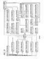
- FIG. 4is a schematic representation of metadata tables for facilitating a schema-neutral storage of information in an application model of one embodiment of a meta-application.
- FIG. 5is a schematic representation of entity data tables for a single entity, for facilitating a schema-neutral storage of information in the application model, in accordance with one embodiment of a meta-application.
- FIG. 6is a schematic representation of link tables that hold information about relationships between entities, for facilitating a schema-neutral storage of information in the application model, in accordance with one embodiment of a meta-application.
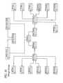
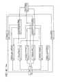
- FIG. 7is a schematic representation of one embodiment of the meta-application, illustrating a particular deployment of monitors for gathering telemetry.
- FIG. 8is a schematic diagram illustrating how a meta-application's analysis subsystem analyzes telemetry, in accordance with one embodiment of the meta-application.
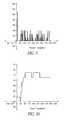
- FIG. 10is a graph of a state metric telemetry signal of a “flat” type of signal category.
- FIG. 11is a graph of a state metric telemetry signal of an “integral” type of signal category.
- FIG. 12Ais a control chart of a telemetry signal of a state metric, in accordance with one embodiment of the meta-application.
- FIG. 12Bis a graph showing an upper portion of a normalcy range of a control chart.
- FIG. 13is a trend chart of a telemetry signal of a state metric, in accordance with one embodiment of the meta-application.
- FIG. 14is a discrete chart for a telemetry signal having discrete values, in accordance with one embodiment of the meta-application.
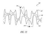
- FIG. 15is a seasonality control chart for a telemetry signal of a state metric, in accordance with one embodiment of the meta-application.
- FIG. 16is a Problem Logic circuit for evaluating a logic rule.
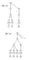
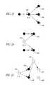
- FIG. 23is a diagram of application model objects and directed links, illustrating a root cause analysis method of investigating incriminating links to find a root cause candidate object, in accordance with one embodiment of the meta-application.
- FIGS. 24 and 25are diagrams of application model objects and directed links, illustrating root cause analysis methods of investigating bystander objects to find a root cause candidate object, in accordance with embodiments of the meta-application.
- FIG. 26is a diagram of application model objects and directed dependency links, illustrating a root cause analysis method of investigating incriminating dependency links to find a root cause candidate object, in accordance with one embodiment of the meta-application.
- FIG. 27is a diagram of application model objects, illustrating a root cause analysis method of finding differences between similar types of objects to find a root cause candidate object, in accordance with one embodiment of the meta-application.
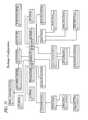
- FIG. 28shows an exemplary application model schema for one embodiment of a meta-application, which manages a deployment of Microsoft ExchangeTM.
- FIGS. 29-40show sub-topological application model schema for specific components of the application model schema shown in FIG. 28 , corresponding to servers, Active Directory, ExchangeTM configuration, WindowsTM services, IIS services, ExchangeTM services, routing, storage groups, public folder hierarchy, databases, third party software, and users associated with the managed deployment.
- FIG. 42is an enlarged view of a portion of FIG. 41 .
- the present inventionincludes systems and methods for programmatically managing deployments of software applications, including those in distributed environments.
- the systems and methods of the present inventionare embodied in a “meta-application,” i.e., an application that at least partially automates the management of one or more other applications.
- these systems and methodsprovide meaningful predictive analysis of deployed software applications, enforce best practices on each deployment, detect the existence of “features” and problem states of the deployment, execute remedial actions associated with the problem states, and/or perform root cause analysis.
- Preferred embodiments of the meta-applicationprovide numerous advantages, including, without limitation, increased deployment uptime, decreased software management costs, reduced need for (potentially erroneous) human intervention, and automatic and continuous leverage of the latest public knowledge about the deployed application.
- Systems and methods of the present inventionare preferably designed to assist system administrators by at least partially automating the entire lifecycle of a managed application, including configuration, provisioning, maintenance, patching, problem diagnosis, healing, and day-to-day operations.
- the meta-applicationimproves and seeks to optimize application stability and performance while also optimizing system resources.
- the meta-applicationis in charge of many of the system administrator activities associated with the managed application(s), including monitoring, updating, configuring, problem pinpointing, repairing, ongoing optimization, and protecting.
- the meta-applicationis preferably configured to quickly pinpoint the cause of a problem and then either automatically repair it or direct manual repair via a human being. Either way, MTTR is significantly reduced.
- the various functions and methods described hereinare preferably embodied within software modules executed by one or more general-purpose computers. These software modules, and the associated databases, may be stored on any appropriate type or types of computer storage device or computer-readable medium. In certain cases, some of the various functions and methods described herein can be embodied within hardware, firmware, or a combination or sub-combination of software, hardware, and firmware.
- FIG. 1illustrates a preferred embodiment of the invention, comprising a meta-application 20 that monitors and manages a deployment 10 (also referred to herein as a “managed application”) of a software application hosted on one or more servers 12 over a computer network 5 , such as a local or wide area network.
- Each server 12may include at least one monitor 14 with one or more probes 16 , and at least one component 18 of the managed application. It is also possible for monitors 14 to reside on the same server(s) as the meta-application 20 , to facilitate “touchless” monitoring (see FIG. 7 ).
- the monitors 14 and probes 16assist the meta-application 20 in obtaining information from, executing actions upon, and executing application analysis in a distributed fashion on, the servers 12 .
- the meta-application 20can be configured to monitor and manage a wide variety of different types of deployments 10 .
- Examples of software applications and hardware environments that the meta-application 20 can monitor and manageinclude, without limitation, servers and storage subsystems, databases such as Oracle Database 10gTM and MSSQLTM, email and/or messaging applications such as Microsoft ExchangeTM, application servers such as WeblogicTM and WebsphereTM, and web servers such as Microsoft IISTM and ApacheTM.
- the meta-application 20is preferably configured to monitor and beneficially manage any application (hardware, software, firmware, or a combination thereof) governed by the equation set forth in the Background of the Invention section of this application.
- the managed application 10is preferably a software application or system that has interfaces or tools for gathering state metrics and for controlling system state.
- the managed application 10may include a number of sub-applications and services.
- the deployment 10can be distributed across servers 12 that are located remotely from one another.
- the meta-application 20can be located remotely from the deployment 10 .
- the meta-application 20can be configured to monitor and manage more than one deployment 10 .
- the meta-application 20is configured to manage only one type of software application or system (e.g., only versions of Microsoft ExchangeTM).
- the meta-application 20can manage different types of software applications.
- the orchestration module 21preferably runs a master algorithm over all other algorithms of the meta-application 20 . All other algorithms are preferably called as subroutines or run in independent threads managed by the orchestration algorithm.
- the orchestration module 21is preferably responsible for starting and stopping major activity threads of the meta-application 20 , such as Problem Logic (described below), when the meta-application as a whole starts and stops, and in between.
- the orchestration module 21establishes the relative priorities of all the major components of the meta-application 20 and evaluates the performance of the system as a whole via an evaluation algorithm.
- the evaluation algorithmapplies group rewards and punishment to continuing tunable system parameter adjustments so as to optimize system performance.
- the orchestration module 21preferably performs scheduling and initiates occasional maintenance, security, backup, and software rejuvenation activities of the meta-application 20 and the managed application deployment 10 .
- the orchestration module 21preferably also communicates and cooperates with orchestration modules 21 of other cohort meta-applications 20 , if any, in a distributed network of meta-applications managing multiple application deployments 10 .
- the knowledge base 22preferably comprises a repository of encoded knowledge about the deployed software application 10 .
- Encoded knowledgecan comprise, without limitation, known problem states or “problems” associated with the deployed application 10 .
- a “problem”is a known problematic condition or behavior of an application or application deployment (portions of Provisional Application No. 60/638,006, to which the present application claims priority, refer to “problems” as “symptoms”).
- the knowledgeis preferably encoded in a form that facilitates automated or computer-implemented analysis of the deployment 10 .
- the task of encoding knowledgecan be performed by human operators (referred to as Knowledge Engineers or “encoders”), but it may also be partially or fully automated within software.
- Knowledgecan be encoded from knowledge base articles of the type commonly used by IT personnel to manually resolve problems.
- a particular knowledge base articlemay describe a problem that occurs when a particular logical combination of conditions or states exist within a deployed software application, and may specify one or more possible remedial actions for addressing this problem.
- the remedial actionsmay similarly be encoded in a format that enables the meta-application 20 to parameterize or configure a remedy for use within the particular deployment 10 of the managed application, and to otherwise control the execution of remedies.
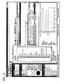
- One example of a source of knowledge that can be encoded and stored in the knowledge base 22is a MicrosoftTM Knowledge Base Article (see FIGS. 22A-B for an example of a MSKB article).
- Knowledgecan also be encoded from other sources, such as documented errors associated with the managed application 10 , best practices that specify recommended configurations of the managed application 10 , existing or customized diagnostic tools, and feedback data collected over time from deployment sites (i.e., knowledge learned from the deployments 10 themselves).
- the knowledge base 22is preferably configured to receive periodic updates as new knowledge becomes available (see FIG. 2 ).
- Knowledgecan be encoded in any suitable format. In a preferred embodiment, knowledge is encoded in XML.
- Knowledge that can be used by the meta-application 20may also comprise algorithms that dynamically detect problems at runtime. Such algorithms can also be stored in the knowledge base 22 .
- the knowledgeis encoded as a plurality of logic rules that describe problems with the deployment 10 and/or deviations from best practices.
- logic rulesare described further below.
- logic rulesare statements that include logical formulae and sub-formulae whose arguments comprise data describing the deployment configuration and behavior.
- a logic rulecan be thought of as a logical combination of conditions; if each condition is met, the rule itself is true.
- a logic rulecan specify the existence of a specific deployment configuration or behavior of the deployment 10 .
- logic rulesmay contain queries for information from the deployment 10 or application model 24 (described below).
- a logic rulecan also specify the existence of “features,” which are described below.
- FIG. 2illustrates a preferred system 50 and method of managing and updating the content of local knowledge bases 22 of a plurality of different meta-applications 20 that monitor and manage a plurality of applications 10 in different deployment sites.
- each deployment siteincludes a managed application 10 , a meta-application 20 , and a local knowledge base 22 .
- the various managed applications 10are the same (e.g., all the applications 10 are versions of Microsoft ExchangeTM). In another embodiment, the various managed applications 10 can be completely different.
- Each managed application 10may comprise a single software application or a set of software applications.
- the methodpreferably involves the encoding 52 of knowledge about the managed applications 10 .
- the knowledge to be encodedcan comprise known problems, remedies, best practices, and other knowledge about the managed applications 10 .
- the encodingcan be done manually, automatically, or a combination of both. Further details about preferred encoding methods are described below.
- the encoded knowledgeis stored in a central knowledge repository 54 . Skilled artisans will appreciate that the central knowledge repository 54 can contain knowledge about all of the different types of applications 10 that are managed by the group of meta-applications 20 . Alternatively, there can be a different central knowledge repository 54 for each different type of managed application 10 . In either case, any number of central knowledge repositories 54 can be provided.
- one or more update servers 56disseminate knowledge updates or patches to various deployment sites of the managed application 10 , via the Internet or another suitable communications network.
- the disseminated updates or patchesmay comprise, for example, updated knowledge or changes to the local knowledge bases 22 , new or updated monitors 14 , revised algorithms, and the like.
- an updatemay be sent to all of the deployment sites to add a newly created logic rule and associated remedies to each of the local knowledge bases 22 .
- the update servers 56can be programmed to send new patches of encoded knowledge to the local knowledge bases 22 according to various different criteria.
- the update servers 56can send knowledge updates according to set periods (e.g., once a day, week, month, etc.) or based upon the amount of new and unsent knowledge stored in the central knowledge repository 54 .
- the update servers 56can also send knowledge updates based upon the importance of the unsent knowledge. For example, logic rules can be rated according to relative importance, so that the most important knowledge rules get sent first. In any case, it will be understood that it is ordinarily preferable to send newly encoded knowledge to the local knowledge bases 22 as soon as possible.
- the update server 56can instruct the meta-applications 20 to remove unneeded knowledge (e.g., older, no longer relevant logic rules) from the knowledge bases 22 , by sending software updates containing removal algorithms.
- each deployment site shown in FIG. 2has a locally installed meta-application 20 , it will be recognized (particularly in view of FIG. 1 ) that the meta-application 20 need not run locally with respect to the managed application 10 . In addition, there need not be a one-to-one correspondence between meta-applications 20 and managed applications 10 . Thus, for example, a single instance of the meta-application 20 could be operated as a hosted application that monitors multiple deployment sites from a remote location.
- the application model 24is preferably a distilled representation of the deployment 10 , augmented with additional information.
- the meta-application 20When the meta-application 20 is first installed or configured for management of the deployment 10 , the meta-application conducts a “discovery” process to populate the application model 24 with useful information about the deployment 10 .
- the meta-application 20preferably runs its discovery process periodically or continuously to dynamically keep the application model 24 up to date.
- the application model 24represents all of the objects of the deployment 10 (like software objects, servers, routers, storage subsystems, etc.) and all of the physical and logical dependencies of these objects.
- the application model 24might store the fact that an ExchangeTM server S 1 has a Storage Group X, which contains a Database Y, which resides on SAN “foo” on Logical Disk D.
- the application model 24also preferably contains metadata for each object, such as data related to the “golden” or most preferred configuration for that object, as well as the object's current configuration.
- the application model 24also preferably contains information about what telemetry “metrics” are relevant to an object, as well as parameterized troubleshooting procedures (“unit tests”), or references to such procedures (which can reside elsewhere), that can be used to measure the health of an object.
- the application model 24can further include information about the relationships between various objects, as well as the normal flow of data and control signals therebetween.
- the application model 24is a “cached” view of the topology of the deployment 10 .
- the meta-application 20would have to always obtain state/configuration information from the deployment 10 , which can overburden the network and the resources of the deployment environment.
- the application model 24is kept in a database and only updated when the deployment state or configuration changes. Note that the application model 24 can advantageously be used by algorithms contained within the problem detector 38 to detect rules-based problems and problems found by conducting encoded diagnostic methodologies, as well as by the root cause analysis module 41 to detect root-causes of problematic conditions. In preferred embodiments, most or all of the components of the meta-application 20 use the application model 24 to perform their associated functions.
- the application model 24can be used by the analysis subsystem 30 and the automation subsystem 32 to dynamically obtain knowledge about the deployment 10 , analyze the deployment 10 for the existence of problems, create deployment-specific plans for remedial actions against the deployment, and perform root cause analysis.
- the application model 24gives the meta-application 20 the context often required for correct analysis. For example, if the meta-application 20 wants to restart an important application service that has failed, the application model 24 can be used to locate the server of that service and to determine all the dependencies of that service, including whether other important services are resident on that particular server. If there are no other important services on the server, then the meta-application 20 can send a restart message to the service. If the restart message does not work, the meta-application 20 can restart the entire server. However, if there are other important services on that server, it may not be desirable to restart the server and disrupt those services. Without this context provided by the application model 24 , the meta-application 20 might mistakenly restart the server and cause additional unwanted problems.
- the analysis subsystem 30is configured to request and receive data from the deployment 10 , analyze the received data, detect “features” (described below) in the data, detect problems with the deployment, select high-level remedies to execute against the deployment, and/or perform root cause analysis (RCA).
- the illustrated analysis subsystem 30comprises a telemetry component 34 , feature detector 36 , problem detector 38 , remedy selector 40 , and root cause analysis (RCA) module 41 .
- the analysis subsystem 30preferably includes a telemetry component 34 that monitors and collects data values of various state metrics associated with the managed deployment 10 .
- state metricrefers to a characteristic, condition, or state than can be measured or tested to generate a data value. State metrics can be time-variant metrics, such as CPU utilization, available disk space, and service availability.
- the collected datais referred to herein as “telemetry” or “telemetry data.”
- telemetryis not intended to imply that data is necessarily collected from a remote source. Rather, the source or sources of the telemetry data may be local to the machine or machines on which the meta-application 20 runs.
- a “telemetry stream”is a data signal for one state metric.
- the telemetry component 34preferably operates with the assistance of the monitors 14 and probes 16 , which reside on the servers 12 of the managed application deployment 10 , on the same server(s) as the meta-application 20 , or on other components.
- the monitors 14 and probes 16provide the infrastructure for the telemetry component 34 to request and gather application state metrics (i.e., telemetry) from the deployment 10 .
- the monitors 14 and probes 16also provide the infrastructure for the automation subsystem 32 to execute remedial actions against the deployment 10 .
- the monitors 14may also be used to distribute execution of analysis tasks that are then communicated back to the analysis subsystem 30 .
- the monitors 14 and probes 16comprise software components. However, hardware components or a combination of hardware and software can be provided for cooperating with the telemetry component 34 and automation subsystem 32 for the purposes described herein.
- the meta-application 20preferably stores collected telemetry data in the telemetry database 26 .
- the analysis subsystem 30uses the stored telemetry data to analyze past (often recent) behavior of the deployment 10 .
- the telemetry database 26manages its own storage and automatically removes aged data.
- the management of the data within the telemetry database 26could alternatively be done by other components, such as the telemetry component 34 .
- the telemetry database 34since many telemetry analyses operate only on recent telemetry data, the telemetry database 34 includes a caching mechanism to more quickly respond to those data queries.
- the meta-application 20preferably also stores features in the telemetry database 26 . Like the telemetry data itself, the features are also preferably automatically removed as they age, albeit preferably at a slower rate than the raw telemetry data.
- the telemetry database 26can form a subcomponent of the telemetry component 34 .
- the meta-application 20runs “best practice plans” that are customized for this deployment 10 . Executing these plans serves to verify that there are no known configuration problems, and that the deployment 10 is in a consistent state and is in conformity with best practices (e.g., the deployment 10 has downloaded and is running the latest patches from the maker of the managed application).
- the feature detector 36continuously analyzes collected telemetry data to detect “features.”
- a featureis a condition or behavior of the managed application 10 that is known to be associated with a potential problem therewith.
- a featurecan be benign, i.e., not in itself being unusual or anomalous. However, a feature often represents an unusual (but not necessarily problematic) condition or behavior of the deployment 10 .
- a featuremight indicate the existence of one or more problems, depending on whether other defined features exist. Examples of features are unusual spikes in CPU utilization, error log entries, loss of network connectivity, failure of a component or subcomponent, storage exhaustion, unusual delays in network transactions, abnormal performance of synthetic transactions, abnormal resource consumption, etc.
- the existence of a featurepreferably causes the problem detector 38 employ algorithms to (1) review the encoded knowledge for problems that are known to possibly cause the detected feature, and (2) possibly initiate more detailed telemetry gathering and direct more extensive troubleshooting of a known problematic component of the deployment 10 .
- One way that the meta-application 20 detects featuresis to create “baselines” of various state metrics associated with the managed application 10 .
- a baselineis a mathematical model that describes the behavior of a state metric during “normal” operation of the managed application 10 , wherein the meta-application 20 determines what is “normal” based on observation of the managed application for a suitable time period.
- the construction of baselines(also referred to herein as “baselining”) can be ongoing and dynamic, to continually reflect the current operation of the managed application 10 .
- a baselinecan be a graph of the normal upper and lower bounds of a state metric as a function of time. If the monitored state metric deviates to a prescribed extent from its baseline, the feature detector 36 registers a new feature in the telemetry database 26 . Baselining methods are described in further detail below.
- the meta-application 20preferably uses baselines in subsequent calculations for optimization, recovery, and root cause analysis.
- the feature detector 36preferably detects features by analyzing telemetry data stored in the telemetry database 26 or telemetry data received directly from the telemetry component 34 .
- the problem detector 38preferably contains algorithms that request and process telemetry and features and identify deployment problems. These algorithms preferably identify proper deployment 10 configuration, procedures to heal the deployment 10 when it has problems, procedures to optimize the deployment when sub-optimal conditions are recognized, and procedures to protect the deployment when it is compromised. These algorithms may also orchestrate other peer algorithms in the problem detector 38 .
- One algorithm, “Problem Logic,”preferably analyzes the logic rules stored in the knowledge base 22 to detect whether any rules are currently “matched” or “true” (i.e., currently exist within the deployment 10 ). As explained above, a logic rule can specify the existence of specific deployment configuration parameters and state metric values. Preferably, logic rules can also specify the existence of one or more features.
- logic rulesmap logical combinations of deployment configuration parameters, state metric values, and/or features to known problems associated with the managed application 10 .
- the problem detector 38only analyzes logic rules that specify features discovered by the feature detector 36 .
- the problem detector 38systematically analyzes some or all of the logic rules in accordance with schedules that are either preprogrammed or set by a system administrator of the managed application 10 .
- the problem detector 38can also be configured to automatically select logic rules to evaluate based on currently identified features and/or problems, thereby troubleshooting the rules in an optimal way.
- the feature detector 36can itself be configured to independently detect problems by dynamically analyzing the deployment 10 based on data gleaned from the application model 24 .
- the knowledge base 22preferably stores information about remedial actions, or “remedies,” that may be performed to eliminate specific problems. Each remedy is stored in the local knowledge base 22 in association with a particular problem. In some cases, a detected problem has more than one remedy, and the remedy selector 40 determines the preferred order in which to execute the remedies (i.e., if the first remedy fails to correct the problem, then the second is executed; if the second remedy fails, then the third is executed; etc.).
- a planis an encoded administrative procedure.
- Each remedycan have one or more plans that contain instructions on how to fix each type of problem.
- a remedycan be thought of as a set of plans and a policy for executing the plans.
- a planis a specific order of steps to address a problem in a specific fashion.
- the plansencode the various actions that the meta-application 20 or the administrator may want to take against the deployment 10 , including management actions like “delete a user from the system,” troubleshooting actions like “restart a non-responding software component,” and remedy actions associated with knowledge base articles.
- the plansare preferably stored in an abstract format that encodes all of the specific actions required and the decision factors that allow the meta-application 20 to customize a plan to a specific deployment 10 . In the illustrated embodiment, the plans are stored in the plan database 28 .
- problemsare detected, they are reported by the meta-application 20 to associated IT personnel, together with associated remedial actions and their plans that may be executed to address the detected problem.
- the meta-application 20may be designed or configured to automatically execute remedial actions associated with detected problems. When a given remedial action is executed, the meta-application 20 preferably evaluates whether the associated problem still persists, and logs the result.
- the automation subsystem 32includes a planning module 42 and an execution engine 44 .
- the planning module 42preferably accepts high-level remedies and converts associated abstract or generalized plans into deployment-specific low-level actions.
- the execution engine 44preferably executes those actions in a consistent and reversible manner against the deployment 10 , and it preferably allows such execution of such actions to be paused and resumed in a consistent manner.
- the automation subsystem 32can preferably also accept high-level management tasks directly from a human administrator of the deployment 10 , convert them into deployment-specific actions, and execute them. In this manner the automation subsystem 32 leverages encoded application knowledge (for example, a plan that encapsulates all the steps required to restore a Microsoft ExchangeTM server to a new machine). Remedies and plans are described in further detail below.
- the meta-application 20may also implement a root cause analysis (RCA) process for resolving less common, or coexisting problems.
- the analysis subsystem 30can include a root cause analysis module 41 that implements the RCA process.
- the RCA processmay be used where, for example, no logic rules exist for mapping a particular problem or set of problems to a corresponding cause or remedy.
- RCAmay also be used in a fault-storm, which is a case where many problems are detected within a short period of time. In this case, the RCA module 41 would determine the most important faults to address first.
- each meta-application 20can be configured to provide feedback 58 that can be used in the knowledge encoding process 52 .
- the feedback 58 provided by a particular deployment sitemay include, for example, some or all of the following information for each problem detection event: the problem detected, the associated logic rule that triggered, the underlying features and/or telemetry data that caused the rule to trigger, the associated configuration state of the managed application 10 at the time the rule triggered, the remedy or remedies executed in response to the problem detection event, and the outcome of each remedy execution event.
- This informationmay be used over time by human personnel and/or automated rules generation and analysis software to adaptively refine the logic rules and remedies stored in the local knowledge bases 22 .
- the meta-application 20is adapted to manage a deployment 10 of Microsoft ExchangeTM.
- the deployment 10is provided on one or more servers 12 , as explained above.
- the meta-application 20preferably runs on a dedicated server 60 , and monitors and manages the Exchange Servers 12 and Active Directory servers 62 over a local area network (LAN) or wide area network (WAN).
- the meta-application 20can also monitor other related components, like a DNS server, SMTP, etc. Skilled artisans will appreciate that the number of servers 12 can be relatively large (e.g., ten to twenty servers 12 ).
- meta-application 20can be employed to manage a wide variety of different types of applications 10 , specific examples of a meta-application are described herein in the context of managing Microsoft ExchangeTM. However, it should be understood that the concepts described herein are not limited to any specific type of application 10 .
- the meta-application 20advantageously increases the availability A of the deployment 10 .
- the meta-application 20seeks to reduce MTTR by providing quick insights to the system administrator on the root causes of problems and providing plans to quickly repair the deployment 10 .
- the meta-application 20reduces unexpected failures, thereby increasing MTTF.
- a reduction in MTTR coupled with an increase in MTTFincreases the overall availability A of the deployment 10 .
- the application model 24( FIG. 1 ) includes detailed knowledge about the application 10 that is managed by the meta-application 20 .
- the application model 24comprises metadata describing the static and dynamic aspects of the environment being managed.
- the application model 24comprises the information listed below. Skilled artisans will appreciate that the application model 24 can consist of more or less than what is listed below.
- the information defined abovecan be captured in the application model 24 , which can be represented as an object graph.
- Gis the abstract graph that describes the complete environment to be managed by the meta-application 20 (it is preferably provided with the uninstalled version of the meta-application), while G* is computed through discovery and populated with actual information. All key components of the meta-application 20 (e.g., monitoring, analysis, automation) can preferably use the application model 24 .
- FIG. 28shows an exemplary application model schema, or object graph, for a meta-application 20 that manages a deployment 10 of Microsoft ExchangeTM.
- FIG. 28shows, at a high level, the topology of the deployment 10 .
- the various boxesrepresent objects of the deployment 10 , and the arrows represent links therebetween.
- the links between the boxescan also be considered as objects of the application model 24 .
- a preferred application model 24stores various metadata, described above, with these objects, including the links. Unit tests can be stored in connection with the illustrated boxes and links.
- FIG. 28One of the boxes shown in FIG. 28 is a box 280 representing servers associated with the deployment 10 .
- FIG. 29shows an object graph for the servers. In other words, FIG. 29 shows all of the instances of servers of the deployment 10 , represented as a sub-topology of the application model schema shown in FIG. 28 .
- FIGS. 30-40show sub-topological object graphs for Active Directory, ExchangeTM configuration, WindowsTM services, IIS services, ExchangeTM services, routing, storage groups, public folder hierarchy, databases, third party software, and users associated with the application model represented in FIG. 28 .
- FIGS. 28-40only illustrate a topology and sub-topologies, and that a preferred application model 24 includes much more information (including metadata about objects, links between objects, data flows between objects, dependences, etc.) than what is shown in these figures.
- the meta-application 20When the meta-application 20 is initially installed, it auto-discovers most or all of the components of the deployment 10 using the abstract application model (G). A description of this set of components is then sent to the application model 24 , which builds a complete context-sensitive model of the deployment (G*).
- the meta-application 20uses information from the application model 24 (if the deployment 10 is ExchangeTM, such information may comprise, e.g., the number of mailboxes, number of servers, network organization of servers, available bandwidth, etc.) to choose a set of monitors 14 to deploy and a set of state metrics to be observed. Then “empirical baselines” for each of these state metrics are chosen.
- the empirical baselinescontain things like the initial set of state metrics important for this deployment, initial values for key system parameters such as CPU utilization, volume of traffic, disk utilization and schedules for maintenance tasks appropriate for this deployment. These empirical baselines are preferably provided with the uninstalled version of the meta-application 20 as part of the abstract application model G. They can be computed by analyses of reference material of the type of software application being managed (e.g., books, websites, knowledge base articles, consultants, etc.) and empirical analyses done on a wide variety of different deployments 10 of the managed application.
- a querying language interfacecan be provided to allow the application model 24 to answer queries received by the analysis subsystem 30 (e.g., by the problem detector 38 , RCA module 41 , remedy selector 40 , or other subcomponents thereof) and/or the automation subsystem 32 (e.g., the planning module 42 , the execution engine 44 , or other subcomponents thereof).
- the querying language interfacepreferably also allows these queries to be indexed and cached to improve querying performance.
- the application model 24preferably allows schema-less storage of its information for seamless upgrading of an installation of the meta-application 20 .
- a software application like the meta-application 20is upgraded, very often the schema (the way in which its data is organized on disk) will change.
- the meta-application 20can upgrade itself and maintain its historical data about the managed application 10 for extended periods of time without restarting.
- a schema-neutral data store moduleis preferably provided, which can accept multiple schemas and query across all of them. This allows data stored in older schemas to still be accessed after a newer version of the meta-application 20 begins using a new schema to store the same type of information.
- a discovery table 64records when discovery (the process responsible for gathering that information stored in the application model 24 ) was conducted. It is used to track which rows in the data tables were discovered at different times. Thus, the discovery table preferably holds all of the known discovery events. In one embodiment, the discovery table has the following columns:
- a schema table 66records all the different versions of the schema that have been installed by the meta-application 20 .
- the schema table 66has the following columns:
- An entity map table 68records the names of the actual tables that hold the data for a given entity. For example, for SQL entities, this table contains the names of all the tables that hold data for different schema versions of an entity. Also, for HDF5 entities, the entity map table 68 holds the names of HDF5 files and the names of the groups. In one embodiment, the entity map table 68 has the following columns:
- An attribute map table 70records the names of the actual columns that hold the data for different schema versions of a given attribute.
- the attribute map table 70has the following columns:
- a link map table 72records the names of the actual tables that hold the links between two specific entities.
- the link map table 72contains the names of all the SQL tables or HDF5 files and groups that hold data for different schema versions of a link.
- the link map table 72has the following columns:
- Entity data tablespreferably hold the actual information for the entities.
- FIG. 5shows features of the entity data tables for a single entity, according to one embodiment.
- each entityhas associated with it a current entity value table 74 , a historic entity value table 76 , and an entity commit table 78 .
- the current entity value table 74holds the most recent information for the entity and preferably has one column per attribute.
- the historic entity value table 76holds all historic values (i.e., a record of previous values) as well as all temporary uncommitted updates. Rows are preferably added to the table 76 each time updates occur to the entity table.
- the entity commit table 78holds an “update sequence number” and a “commit time” for each update.
- the name of the current entity value table 74can have any of a wide variety of forms, such as “entity-name_D schema-id” (e.g. “HOST_D040812 — 1”). As mentioned above, the table 74 preferably records the current information for an entity. In one embodiment, the table 74 has the following columns:
- the name of the historic entity value table 76can have any of a wide variety of forms, such as “entity-name_H schema-id” (e.g. “HOST_H040812 — 1”). As mentioned above, the table 76 records the historic information for an entity and preferably has the following columns:
- the name of the entity commit table 78can have any of a wide variety of forms, such as “entity-name_C schema-id” (e.g. “HOST_C040812 — 1”). As mentioned above, the table 78 records the commit status of the updates to the entities and preferably has the following columns:
- FIG. 6shows two tables that preferably hold the actual information about related entities.
- each linkhas associated with it a link table 80 and a link commit table 82 .
- the link table 80preferably holds recent and historic information for the links, as well as details of a specified type of relationship between two entities.
- the link commit table 82preferably holds an update sequence number and a commit time for each update to its corresponding link table 80 .
- the name of the link table 80can have any of a wide variety of forms, such as “entity1-name_entity2-name_type_L schema-id” (e.g. “DOMAIN_HOST_PC_L040812 — 1”).
- the link table 80preferably records the current and historic information for all links between two entities.
- the link table 80has the following columns:
- the name of the link commit table 82can have any of a wide variety of forms, such as “entity1-name_entity2-name_type_C schema-id” (e.g. “DOMAIN_HOST_PC_C040812 — 1”).
- the link commit table 82records the commit status of the updates to the links.
- the table 82has the following columns:
- the meta-application 20includes functionality for performing efficient querying of static queries.
- the meta-application 20preferably knows beforehand the forms of all possible data queries that the data store is able to perform, but not always the specific data to be queried. Specifically, the meta-application 20 preferably knows what tables will be queried and which columns will be used for query constraints and joins. In this embodiment, the meta-application 20 may sometimes know exactly what values will constrain a query, but generally it will not. Since the data in the data store can change, it may not be useful to cache the results of a known query. However, it is useful to cache the data structures used to perform the query, which allows for quicker responses to queries.
- the meta-application 20preferably includes a persistence system that caches and maintains a known set of queries that the meta-application 20 might execute as well as usage frequency information for each query.
- queries that are completely boundare stored in a first cache (closest to returning the result). These bound queries already know exactly what table (e.g., SQL table) and constraints to use.
- a second cachecontains queries that are not completely bound, such as a query that might lookup a server with a name to be provided when the query is executed. These unbound queries can be though of as prepared statements.
- the persistence system of the meta-application 20preferably also maintains a cache of frequently accessed data in memory, organized for fast lookup and good locality of reference, for the queries that are most frequently executed. So if a specific query looks in table foo for column bar with a specific value, rows in table foo will be split into two cached tables, one for column bar and one for the other columns.
- the meta-application 20uses monitors 14 and probes 16 to collect telemetry data (also referred to herein as “state metrics” or “telemetry metrics”) from the deployment 10 of the managed application.
- a monitor 14encapsulates all the different ways that the meta-application 20 can gather telemetry data from, and control, the deployment 10 .
- Each probe 16preferably runs inside of a monitor 14 and is responsible for gathering data for a specific telemetry metric.
- the analysis subsystem 30is preferably concerned with gathered telemetry metrics, and leaves the details of how to gather them to the monitors 14 .
- the automation subsystem 32preferably just worries about “operators” and lets the monitors 14 deal with how to execute them on the deployment 10 .
- a monitor 14is a piece of code, such as executable program or DLL (dynamic link library) file.
- the application model 24can maintain a mapping of all possible telemetry metrics associated with each application model component/object. This allows algorithms to dynamically create problem identification procedures at runtime without the need for pre-built rules.
- Monitors 14can preferably use both local and remote APIs (application program interfaces) to access the managed application 10 . This simplifies installation of the meta-application 20 , because it is not necessary to modify any deployment 10 components in order for the meta-application to monitor them. In addition, certain components, like routers and firewalls, can typically only be managed via remote APIs. Microsoft WindowsTM has the ability to monitor and remotely control most deployment 10 components via remote APIs. Thus, remote monitors 14 can provide a significant amount of the functionality required to manage the deployment 10 .
- remote APIsapplication program interfaces
- Monitors 14can reside locally with respect to the deployment 10 , or locally with respect to the meta-application 20 .
- one monitor 14is provided on each server 12 of the deployment 10 .
- the monitor 14can preferably use all the remote and/or local APIs (some application-specific APIs are only accessible locally on the server 12 on which the application is installed).
- local monitors 14can minimize the bandwidth they use by sending only “diffs” of telemetry data (differences between two data sets).
- Local monitors 14can preferably also operate when network connectivity to the meta-application 20 server (the meta-application 20 is preferably provided on one server, but could be provided on a plurality of servers) is lost.
- a local monitor 14can preferably batch collected data and send it when connectivity is regained.
- Local monitors 14preferably also have the ability for local analysis of telemetry, as well as identification of features or problems and associated resolutions, thus providing a distributed analysis capability to the meta-application 20 . For example, if the monitor 14 senses that the deployment 10 is about to crash, the monitor can gracefully and immediately shut down services to minimize data loss.
- the meta-application 20preferably analyzes and chooses (e.g., when it is first installed) the set of telemetry required to manage, the application deployment 10 .
- Monitors 14can be categorized by the application component they monitor and control. For example, there may be an ExchangeTM Server monitor, a Microsoft DNS Server monitor, a Cisco PIX FirewallTM monitor, etc.
- the meta-application's knowledge base 22preferably has a mapping of telemetry metrics to monitors 14 . Monitors 14 can register themselves with the telemetry component 34 (discussed below), which then configures each monitor 14 with respect to the type and frequency of telemetry required.
- FIG. 7shows a meta-application 20 that manages two different application platforms 84 and 86 .
- the meta-application 20comprises a controller 88 and an administrative user interface 29 (illustrated as a graphical user interface or GUI).
- the controller 88may be implemented on one or more different servers and includes the analysis subsystem 30 and automation subsystem 32 discussed above.
- monitors 92 and 94are also shown. As shown, the monitors can reside either locally with respect to the managed application (such as the monitor 92 ) or within the controller 88 (such as the monitor 94 ).
- the monitor 92resides locally within the application platform 84 , and sends telemetry to the analysis subsystem 30 , possibly using SOAP (Simple Object Access Protocol).
- SOAPSimple Object Access Protocol
- the automation subsystem 32can send deployment healing commands to the monitor 92 for healing the application platform 84 .
- the monitor 94resides within the controller 88 , and gathers telemetry from application platform 86 via any of a variety of protocols, such as SNMP (Simple Network Management Protocol), RPC (Remote Procedure Call), and the like.
- the automation subsystem 32can send healing commands to the monitor 94 , which remotely executes them against the application platform 86 .
- each monitor 14is implemented as a “container” process with the ability to load new probes 16 at runtime (on WindowsTM platforms, monitors 14 can preferably load new probes 16 as DLL files during runtime using the LoadLibraryTM mechanism).
- the probes 16can be thought of as new telemetry capabilities.
- Monitors 14send telemetry to the meta-application 20 in chunks of data called “telemetry packets.”
- the telemetry component 34can preferably configure the container process to control the frequency with which it sends telemetry packets and the type of telemetry metrics in each packet.
- the container processis preferably also configurable with respect to the protocol it uses to send the telemetry packets. Each packet can be tagged with a “priority” that the meta-application 20 can use to determine the packet's importance.
- the monitor 14can use platform APIs to gather all requested metrics, form a packet, and then send the packet using the negotiated protocol.
- FIG. 8illustrates preferred methodology or process flow of the analysis subsystem 30 , as it pertains to Problem Logic (discussed below).
- the telemetry sent by the monitors 14is received by the telemetry component 34 , which processes the telemetry (discussed below).
- the meta-application 20can be configured to send urgent telemetry (e.g., telemetry that clearly or probably comprises evidence of a problem with the deployment 10 ) directly to the problem detector 38 , while the rest of the telemetry is stored in the telemetry database 26 .
- the feature detector 36analyzes the received telemetry to detect features, which are passed on to the problem detector 38 .
- the feature detector 36may use feature detection algorithms 25 (discussed below) to detect the features.
- the problem detector 38uses the knowledge from the knowledge base 22 to detect problems associated with the detected features.
- the remedy selector 40then analyzes the detected problems to identify appropriate remedies and develop a healing strategy. Information associated with the detected problems and remedies are then sent to the automation subsystem 32 .
- the telemetry component 34 , feature detector 36 , problem detector 38 , and remedy selector 40can advantageously use information received from the application model 24 to perform their associated tasks.
- the analysis subsystem 30is where the meta-application 20 does its telemetry analysis and problem identification.
- the illustrated meta-application 20uses a staged approach to telemetry analysis with analyses getting increasingly complex as the data proceeds to the next stage.
- the analysis subsystem 30is preferably heavily multithreaded to maximize responsiveness. Also, because much of the analyses are not synchronized and their execution run at different rates, the architecture preferably allows related tasks to have disparate execution times while still being able to cooperate with each other.
- Each thread poolpreferably has synchronization data structures that reduce the complexity of global thread management.
- Telemetry gatheringmay require quasi-realtime processing constraints, so that the meta-application 20 can avoid dropping telemetry or overflowing network buffers.
- all telemetry-processing tasksare preferably given a priority and are executed in priority order. If tasks need to be dropped, then preferably only the lowest priority tasks are eliminated.
- the entire telemetry-processing loopis advantageously multithreaded.
- the most time-sensitive taskis performed by the telemetry component 34 , which preferably monitors all of the incoming telemetry and prevents overflow of network buffers.
- a telemetry priority queuecan be provided to decouple the telemetry component 34 from the rest of the analysis subsystem 30 , so that the component 34 can feed telemetry packets to the TPQ without regard for how quickly the processor thread is taking telemetry tasks off of the TPQ.
- the thread pool of the telemetry component 34preferably accepts telemetry from monitors 14 and then labels each packet with a priority.
- the telemetry packetis then inserted into the TPQ that is sorted by telemetry priority.
- a scheduled priority queuecan maintain “scheduled” tasks sorted by task priority.
- the SPQ prioritiesare preferably in the same “units” as the TPQ priorities to facilitate comparison against each other.
- the meta-application 20preferably inserts tasks into the SPQ when it needs to execute an internal task, such as responding to updates from the update server 56 ( FIG. 2 ) or regular configuration synchronization with the application model 24 .
- the priority of a scheduled taskis zero when it is not time for execution, and increases over time after it passes its scheduled time of execution. Tasks also may change in priority as other algorithms measure and record their utility. The highest task in both queues is compared and the higher priority task is chosen.
- the chosen taskis then assigned to a thread from the thread pool of the telemetry component 34 .
- Packetsare first split into their constituent parts.
- Each telemetry partis then processed according to its type.
- Each telemetry typehas a predetermined sequence of tasks that are invoked from the processor thread. These tasks include things like insertion into the telemetry database 26 and feature detection.
- the task of gathering up all relevant information to effect measurementcan be burdensome, especially in systems where many different code points in numerous contexts might want to gather data.
- this taskis simplified by providing an application model 24 , which is a well-structured database representing a distilled view of the environment where things are measured.
- the application model 24advantageously provides a means of extracting metadata relevant for telemetry measurement.
- the application model 24helps to reduce the amount of “work” that the meta-application 20 needs to do in order to gather information about the deployment 10 . In these embodiments, it is more convenient to place the burden of gathering information on the meter itself.
- the general method of data collectionis as follows.
- the measurement “client”e.g., the monitor 14
- the measurement “server,” specifically the meter or piece of infrastructure that creates the metere.g., the meta-application controller 88 of FIG. 7
- the code that acts as a measurement clientbecomes much simpler as a result, and the metering system becomes much more flexible, maintainable, and extensible.
- the network costs of transmitting the duplicate copies of a given meter to the point of data collectionis low compared to the overall cost of transmitting the resulting metrics back to the point of meter creation. It is therefore not too costly to allow these redundant copies of meters to run to the data collection point. It is very costly, however, to effect separate measurement of the same data source for each copy of the meter, to arrive at what is essentially the same set of metrics.
- the monitors 14are preferably configured to prevent redundant measurement of data in distributed systems.
- Each monitor 14preferably recognizes redundancies in the different metering requests arriving at a data collection point, and effects only a single stream of measurements to derive all the metric values to be sent back to those elements in the analysis subsystem 30 requesting the measurements.
- the metric setcan be sent back to each originating host/process separately and “demultiplexed” there to advise each separate requester (typically the meter creators) of the metrics' values.
- filters or aggregatorsare applied to collected telemetry data to lessen the network burden of sending collection metrics from the data collection point (e.g., monitors 14 ) to the data consumer (e.g., analysis subsystem 30 ).
- a set of postprocessorscould be constructed as components separate from the meters, with each postprocessor being widely applicable to a number of different kinds of meters. Effective postprocessing then is a matter of creating the appropriate meter, and then attaching the appropriate postprocessor to the meter.
- metric valuesstate metrics
- those metricsmake their way to the postprocessor, which then applies appropriate filtering, aggregation, and/or transformation to those input metrics to generate a separate stream of output metrics.
- the number, nature, and content of the output metricsneed not correspond tightly to the input metrics.
- the postprocessorusually changes the nature of the output data, sometimes drastically.
- the meter/postprocessor couplingsends back to the data consumer only the output metrics from the postprocessor.
- postprocessorsA variety of different types are possible.
- one type of postprocessoris an IDENTITY postprocessor, which does not change the meter output in any way. In this case, the coupling of the meter and postprocessor generates results identical to what would have been generated by the meter alone.
- Another type of postprocessoris one that filters data according to some static or dynamic criteria, allowing input metrics through as output metrics without modification if they match the filtering criteria, and completely eliminating the input metrics otherwise.
- Yet another type of postprocessoris one that applies some formulaic transformation. For example, such a postprocessor can double the value of each metric, or apply a “lookup” table function to metric values. Skilled artisans will appreciate that other types of postprocessors may be desirable and useful.
- a postprocessorcan also be a composite of several other types of postprocessors.
- Postprocessorsmay also be useful in ways other than limiting network traffic. For example, in some embodiments, postprocessors make the data consumers in the analysis subsystem 30 much easier to construct because some of the data processing burden occurs at the point of data collection (e.g., the monitors 14 ), thus simplifying the content of the telemetry stream.
- the monitors 14can avoid duplicating measurements and generation of redundant metrics at the point of data collection
- similar conceptscan be applied to postprocessing.
- the same raw measurementthe data-source-facing action
- different postprocessorscan be applied to the metrics stream to generate two separate sets of metrics, as desired by the metrics consumers (in the illustrated embodiment, elements of the analysis subsystem 30 ).
- Two different data consumerscan, of course, specify the same (to a sufficient degree) meter/postprocessing coupling, in which case the whole pipeline at the point of data measurement is shared for both (for the data-sink-facing action).
- a meterpreferably has a “source-facing hash” that combines elements relevant to the meta-application controller 88 (e.g., machine name, telemetry name, etc.).
- the source-facing hashis derived from the meter's “significant and source-relevant attributes.”
- a meter/postprocessor couplingpreferably has a “sink-facing hash” that combines elements relevant to the monitoring APIs of a server 12 of the deployment 10 (e.g., which APIs are being used, which components are being monitored, how many hooks are in this server, etc.).
- the sink-facing hashis derived from the coupling's “significant and sink-relevant attributes,” the sink-relevant attributes being a superset of the source-relevant attributes. It is also possible that information present on the meter and/or the postprocessor can be “advisory” or “suggested” and not count as relevant attributes for purposes of this discrimination.
- the systemuses the source-facing hashes and sink-facing hashes to eliminate redundant meter gathering and redundant post processing, respectively.
- Redundancycan also be avoided in transmitting all metrics streams back to data consumers in the analysis subsystem 30 .
- the monitor 14transmits only one copy of the data back to the single process (and/or host) that may host multiple data consumers for identical meter/postprocessor couplings.
- the data-consuming sidecan worry about notifying all consumers of newly arrived metrics data (demultiplexing).
- the meta-application 20is preferably configured to leverage existing data collection infrastructure of the deployment 10 , if any exists.
- the monitors 14are configured to collect metrics through different native APIs on a given platform (e.g., Win32, Linux kernel interface, etc.). Metrics can also be collected through a low-level measurement service provider (e.g., WMI on WindowsTM), or through other products that collect and aggregate such information.
- the meta-application 20can also be configured to employ different methods for measuring the same data according to various criteria.
- the meta-application 20can measure telemetry data based on global system-determined or user-specified preferences for different measurement methods.
- measurement preferencescan be specified on a per-meter basis. For example, a CPU measurement might take fewer resources on a server 12 of the deployment 10 than page faults per second. As another example of per-meter measurement preferences, it might not make sense to measure disk usage more than once a minute.
- the meta-application 20can also collect telemetry data based on the current availability of measurement resources. Also, some data collection API's may not be reliable, in which case the monitor 14 should retry using another API. Skilled artisans will understand that other data measurement preferences can be provided at the same or other granularities. Specific policies for how to measure and cache specific telemetry metrics can be stored in these preferences.
- the meta-application 20can be configured to keep track of which allowable measurement methods are currently available, as well as those that do not work. Also, the meta-application 20 can be configured to dynamically “arbitrate” the measurement of a given meter between different measurement points and measurement methods, based on current availability and preference. In one embodiment, the meta-application 20 always attempts to measure the meter by selecting a currently available method having the highest priority, and switching the method based on varying availability, preference, and prohibitions.
- this sectiondescribes algorithms 25 and structures used by the analysis subsystem 30 to identify features from raw telemetry data, create “baselines” for gathered telemetry signals, and create normalcy bands for the telemetry signals. In the illustrated embodiment, these activities are performed by the feature detector 36 .
- the followingdescribes preferred embodiments of the feature detection algorithms, structures, and methodology of the meta-application 20 . Skilled artisans will appreciate that many variations of these are possible.
- the meta-application 20preferably includes telemetry analysis algorithms 25 ( FIG. 8 ) that identify suspicious or anomalous trends or states from raw telemetry. Streams of telemetry are analyzed differently depending upon the type of telemetry. Numeric telemetry is analyzed using statistical techniques, and when a telemetry value of a particular stream does not match a statistical profile for the stream, a feature is generated. Other types of telemetry are analyzed using pattern-matching techniques. All feature-detection algorithms finish by adding detected features to a “feature list,” which allows different algorithms to synchronize themselves. The feature list is preferably stored in the telemetry database 26 .
- Each featurepreferably has an associated lifetime that the meta-application 20 uses to determine when it is appropriate to remove the feature from the feature list. Removal allows the meta-application 20 to prevent false positives and to clean out features that have not affected application performance or stability. Note that if a feature did have such an effect, it would have triggered a problem (described below), and the meta-application 20 would have changed the feature's lifetime value. Further, if the meta-application 20 resolves the detected problem, then the feature itself should disappear.
- the meta-application 20utilizes telemetry streams from a managed application 10 to determine the health of said application, possibly using metadata about appropriate telemetry for each application component from application model 24 .
- the algorithms 25are preferably configured to detect whether a specific stream of telemetry shows the existence of specific anomalous states in the deployment 10 or a component thereof, such as an unusually slow CPU, a hard disk that is almost full, message queues that are growing at a high rate, or email delivery that is slow.
- the feature detector 36preferably uses the algorithms to mathematically analyze the raw numerical telemetry to determine if certain anomalous conditions are met. This section describes some of the techniques used to analyze non-cyclical and non-linear telemetry signals.
- a preferred methoduses a “classification algorithm,” a “modeling algorithm,” and “control charts.”
- the classification algorithmrecognizes telemetry signals or streams as belonging to one of a plurality of signal categories, each category describing the general type of signal. For example, in one embodiment the classification algorithm uses signal categories entitled “constant,” “flat,” “integral,” “polynomial,” “noise,” “poles,” or “times” (or alternative titles) defined as described below. A different set of predefined signal categories may alternatively be used.
- the modeling algorithmwhich can be recursive with respect to itself and the classification algorithm, computes numerical parameters of a mathematical model of a telemetry signal (e.g. mean and standard deviation of a normal distribution modeling white noise.)
- the mathematical modelsare used for “baselining” and feature detection.
- the classification algorithmdynamically analyzes a stream of numerical data to mathematically determine the signal category to which it belongs.
- the signal categoriesdescribe fundamentally different types of signals.
- a constant streamcontains the same numerical value repeated forever (e.g., 5, 5, 5, 5, 5, 5, 5, 5, 5, . . . ).
- a pole streamtends to have two classes of values. The majority of the pole signal values are in one numerical range (e.g., zero), and a minority of the pole signal values are in another numerical range.
- FIG. 9shows an example of a poles signal.
- a flat streamtends to contain runs of the same numerical value (e.g., 5, 5, 5, 5, 5, 5, 5, 5, 5, 5, 5, 5, 5, 5, 5, 5, 5, 7, 7, 7, 7, 7, . . . ).
- FIG. 10shows an example of a flat signal. An integral stream either constantly increases or decreases in value.
- the meta-application 20preferably identifies each of these signal categories by its specific mathematical properties. Accordingly, the meta-application 20 conducts a test for each category, where each test may be generated as a result of processing knowledge stored in the knowledge base 22 or generated dynamically by a higher-level feature detector. As each telemetry feed is monitored, it is classified into one of these categories by conducting each category's test.
- the integral, poles, and times categoriesare compound or recursive, meaning that they build upon another category, such as polynomial. So a feed might be categorized as a “times” feed combining polynomial and noise streams.
- the modeling algorithmuses these signal category classifications to generate a description of each feed.
- Each mathematical categoryhas its own specific set of statistical measures to describe the values in the feed.
- the constant categoryonly has the value of the numbers in the feed.
- the flat categorymodels both the various values of the feed and the size of the changes in the feed when they occur. So the flat category model is recursive and is composed of a model representing the various y values of the feed and another model representing the size of the non-zero changes in y.
- the integral category modelrecords whether the feed is increasing or decreasing and the recursive model representing the first derivative of the stream.
- the polynomial modelrecords the equation that describes the telemetry stream.
- the noise modelis represented by either a Gaussian or Gamma distribution.
- the poles modelcontains a recursive model representing the height of the “spikes” or “poles” of this telemetry feed.
- the times modelrecords the two recursive models used to represent this telemetry feed. These values are computed and can be used to detect abnormal conditions that are registered in the telemetry database 26 as features.
- These mathematical modelscan be updated periodically (either manually or by the meta-application 20 ) or dynamically (by the meta-application), based upon new telemetry streams and/or modifications of the formulae for computing numerical parameters of the mathematical models. Such modifications may be based upon, for example, knowledge learned by analyzing the historical use of the deployed software application 10 , feedback received from persons that use or control the deployed software application 10 , and/or new publicly available knowledge of the software application 10 . For each component of the model (poles, flats, etc.), a type of “control chart” (described below) can be created to profile that portion of the telemetry signal.
- the classification or assignment of a telemetry signal to a signal categorycan be accomplished dynamically by the meta-application 20 based upon an analysis of a received telemetry signal.
- the classification or assignment of a telemetry signal to a signal categorycan be done prior to monitoring the telemetry signal, based upon knowledge of the particular metric being monitored. For example, it may be known beforehand that, in a given deployment of the software application being managed, a particular metric is always constant (the “constant” signal category) or always oscillating for short periods between different values (“flats”). In such cases, the meta-application 20 can be configured to assign this telemetry signal to the known signal category without executing the classification algorithm for this particular metric.
- the analysis subsystem 30is preferably configured to generate numerical charts for analyzing real-time telemetry streams, for the purpose of detecting features that can be entered into the meta-application's Problem Logic circuitry (described below).
- FIG. 12Ashows an example of a control chart 95 for a given telemetry metric.
- the control chart 95shows a telemetry signal 94 .
- a normalcy range of the telemetry signal 94is characterized by an upper threshold 91 and a lower threshold 93 .
- the upper threshold 91is characterized by an upper zero-confidence level T 0 (feature confidence equals 0), an upper trigger-confidence level Tc (feature confidence equals c), and an upper full-confidence level T 1 (feature confidence equals 1), which are described below.
- control chartscan have several different forms, depending upon the telemetry signal.
- the telemetry signal 94reaches points 106 , which can be considered as anomalous behavior of the measured metric and can be registered as features in the telemetry database 26 .
- the feature detector 36When the real-time telemetry signal 94 crosses above the upper threshold 91 or below the lower threshold 93 (and more preferably the trigger-confidence levels T c thereof), the feature detector 36 preferably generates a corresponding feature. Fine-grained control can be provided by specifying a preprocessing smoothing average window, a required “sustain time” for a deviation, and a trigger confidence level. Thresholds of numerical charts can measure a telemetry signal absolutely or statistically.
- a monitored metric's normalcy rangepreferably has a low threshold and a high threshold (either threshold is optional).
- a thresholdis an interval [T 1 ,T 0 ] or [T 0 ,T 1 ].
- the feature detector 36( FIG. 1 ) preferably initiates feature generation at the “trigger” confidence level T c , and preferably continues generating features until the confidence returns to 0.
- Feature confidencecan ramp up linearly within [T 0 ,T 1 ] (i.e., confidence is 0 at T 0 , c at T c , and 1 at T 1 ).
- the problem detector 38can preferably accept a profusion of features generated with different confidence values.
- FIG. 12Cshows a “confidence curve” 192 mapped to the telemetry value.
- the confidence curve 192is a piecewise linear function clamped to interval [0,1].
- superimposed on the confidence curve 192are vertical dotted lines 194 , 196 , 198 , 200 , 202 , and 204 .
- the dotted lines 200 , 202 , and 204respectively represent a zero-confidence level, a trigger-confidence level, and a full-confidence level associated with an upper threshold of the telemetry signal.
- the feature detector 36generates new features with corresponding confidence values according to the following methodology, it being understood that other methods are also possible.
- Mu ( ⁇ )is the mean of the data added to the chart.
- Sigma ( ⁇ )is the standard deviation of the data added to the chart.
- “Forget Samples” (N F )is the maximum number of samples retained in the memory of the chart. When this limit is reached, adding a new point will push out the oldest point.
- “Forget Time” (T F )is the maximum time that a sample is retained in the memory of the chart. When the time coordinate x of a point is too old compared to the time coordinate x of the most recent point, then the old point is purged.
- “Low”refers to a chart's low threshold, which is specified by a triple [true,L 1 ,L 0 ] or [false,L c ,c].
- “High”refers to a chart's high threshold, which is specified by a triple [true,H 1 ,H 0 ] or [false,H c ,c].
- the thresholdis [H 0 ,H 1 ].
- “Sustain Samples”(N S ) is the minimum number of points required to sustain a positive confidence deviation before a feature is generated. “Sustain Time” (T S ) is the minimum time required to sustain a positive confidence deviation before a feature is generated.
- points (x i c y i )are progressively added to the chart by an incoming signal.
- the x-coordinateis time and the y-coordinate is some measured telemetry metric.
- N F of pointsare remembered, and points are remembered only for a limited duration of time T F , where passage of time is indicated by the most recent point added to the chart.
- the mean ( ⁇ ) and standard deviation ( ⁇ ) of the dataare preferably determined by exponentially weighted moving averages (EWMA):
- zy i - ⁇ ⁇ The z value can be reported when a feature is detected and registered.
- FIG. 13shows a trend chart 106 for a monitored metric.
- the chart 106includes two different bands.
- the top bandshows an incoming telemetry signal 108 for the monitored metric.
- the lower bandshows a waveform 110 , which is the incoming signal 108 processed to detect “rising trends” and “descending trends.”
- the processed signal 110is fed into a control chart 112 , which is similar to the chart 95 shown in FIG. 12A .
- the upper and lower thresholds of the control chart 112are each characterized by a zero-confidence level T o corresponding to feature confidence of zero, a trigger-confidence level T c corresponding to feature confidence of c, and a full-confidence level T 1 corresponding to feature confidence of 1.
- the signal processinggenerates a positive or negative pulse when a rising or descending trend is detected.
- the squares 113are features.
- cyclic behaviorcan be observed in the performance of deployments 10 of infrastructure applications due to the patterns of human users. For example, for a deployment 10 of Microsoft ExchangeTM, every morning at 9 am mail servers might generally experience heavy load because everyone checks their email when they arrive at work. In another case, a large batch of emails may be sent at the end of each quarter to announce results to investors and shareholders of a financial company.
- managed applications 10can have internally scheduled activities, such as daily backups, that can impact performance.
- FIG. 15shows a “seasonal control chart” 146 , which is preferably generated by the analysis subsystem 30 of the meta-application 20 for some or all of the monitored state metrics from the deployment 10 .
- seasonal control chartscan be generated for those state metrics that are known or observed to behave cyclically.
- the chart 146shows an input telemetry signal 148 for a given state metric (shown as a dotted line), and a normalcy band indicated by two lines 152 .
- the normalcy bandrepresents expected norms for a specific time of the, e.g., day, week, month, or year.
- the waveforms of the illustrated seasonal control chart 146are computed according to the following method. However, skilled artisans will understand from the teachings herein that other methods for computing seasonality waveforms can be used.
- the analysis subsystem 30lets a variable P be the period of the seasonal control chart (e.g. the time cycle) C.
- the seasonal control chartcontains points (xi, yi). The distance between two films x and xi is given by the following equation:
- Kernel smoothinguses a nearest neighbor approach to determine the smoothing function.
- a function S(x)is defined as the c closest points of C to x, the c nearest points (x i , y i ) to x as measured by d(x, x i ).
- the weights of the kernel smootherare
- ⁇ ⁇ ( x ) 2⁇ ( x i , y i ) ⁇ S ⁇ ( x ) ⁇ w ⁇ ( x , x i ) ⁇ ( y i - ⁇ ) 2 ⁇ ( x i , y i ) ⁇ S ⁇ ( x ) ⁇ w ⁇ ( x , x i ) Mu and Sigma are finally used to determine if a future data point falls outside of expected norms for a specific time of the day, week, month, year, etc. When a telemetry signal falls outside of these control lines (normalcy bands), a feature is generated, just like the control chart model ( FIGS. 12A-C ).
- Some telemetry signalsare “discrete,” meaning that they are made up of (x i ,y i ) points where y i take on discrete values.
- signals consisting of service state values (stopping, paused, running) or event ID'sare discrete signals. Since discrete values are not necessarily numerically comparable, numerical charts may not apply to discrete signals.
- feature detection methodscan also be employed, such as monitoring application error logs and conducting unit tests (e.g., by using “shims”) on components of the application deployment 10 .
- featuresare shown in the table below, for an embodiment in which the meta-application 20 monitors and manages a deployment 10 of Microsoft ExchangeTM.
- each rowis a specific feature or “feature predicate” (explained below in the Problem Detection section).
- the “Name”is the name of the feature.
- the “Type”describes the method employed to detect the feature.
- the “Telemetry Meter”is the specific state metric from which the feature is detected. It will be appreciated that a feature need not always stem from a particular monitored state metric.
- Predictionis the act of guessing future values for some stream of telemetry data.
- the meta-application 20can use prediction methods for a variety of purposes associated with managing a deployment 10 , such as predicting the exhaustion of fixed resources (e.g., disk space), optimizing resource utilization (together with “provisioning”), and performance optimization. Predictions can be made about specific state metrics, the prediction of which might require multiple streams of telemetry. For example, a potential use of prediction is to predict the amount of free disk space given a list of disk performance metrics such as “disk writes/per second” or “current disk usage.” In this example, several streams of disk-related telemetry would be used as input.
- the analysis subsystem 30predicts the future behavior of a state metric by computing a mathematical model of the metric's telemetry signal as a function of time, as described above in the Feature Detection section of the present application, and then simply computing the metric's value at a given future time t. Skilled artisans will appreciate that other types of prediction methods can be employed.
- Provisioningis the process of determining the ideal way to distribute resource usage across several resource providers (e.g., the CPU is a resource provider). Future resource utilizations are used as the input to the provisioning algorithm instead of the current rates of resource utilization. This allows the meta-application 20 to better predict good distributions of resources for some time in the future, instead of an ideal distribution for the current situation.
- the third caseinvolves optimization of the managed application 10 .
- infrastructural applicationshave a variety of tuning parameters that can be used to improve performance in different hardware and network environments.
- the size of the TCP (Transmission Control Protocol) sending queue in the OS network stackwill have different optimal values in different networks.
- the meta-application 20can use the prediction algorithm to determine the optimal settings for these tuning parameters.
- Problem Logicpreferably uses an advanced “incremental query processor” configured to very quickly match a logical combination of features to problems defined by the Problem Logic rules stored in the knowledge base 22 .
- Problem LogicWhen a feature is triggered, Problem Logic preferably uses a “discrimination network” (described below) to quickly determine which logic rules are potentially affected; however, a discrimination network is not absolutely required.
- Problem Logicmay also evaluate raw telemetry data for purposes of detecting problems. Also, as features are added and removed from the feature list (preferably stored in the telemetry database 26 ), the query processor reconfigures itself to optimize problem detection. Matched problems are added to a “problem queue” (PQ). Each problem is assigned a “severity” and matched problems are sorted by severity in the problem queue.
- PQproblem queue
- the meta-application 20can change problem severity as it rates the impact of problems on the deployment 10 and also as it gets updates from the update server 56 ( FIG. 2 ). Also, the associated feature that caused the problem may bump up the severity of the problem. For example, a feature resulting from a telemetry signal diverging from its baseline normalcy band by six standard deviations might produce a problem with a higher severity than if the signal diverged from its normalcy band by only two standard deviations.
- the Problem Logicis embodied in the logic rules stored in the knowledge base 22 .
- the Problem Logicemploys a language that is a modification of First Order Logic, and which includes temporal, causal, and modal operators. This language is used to encode the known problems' descriptions into the logic rules, which Problem Logic executes to determine if any of the encoded problems are currently present within the deployment 10 .
- the meta-application 20is preferably configured to analyze and quickly respond to large amounts of data. Accordingly, Problem Logic is preferably fast enough to be used in a real-time system. To accomplish this goal, Problem Logic is implemented by logic circuits similar to the hardware logic circuits on the computer chips of modern day computers, which are known to be fast. The Problem Logic circuits are not quite identical to hardware logic circuits because Problem Logic circuits push more than single bits of knowledge at a time along their “wires,” which are preferably virtual.
- a logic rule or simply “rule”is a logical formula composed of predicates, logical operators (such as AND, OR, THEN, etc.), mathematical operators (such as less than, difference, sum, etc.), free variables, and constants.
- the formuladescribes how to recognize problems of the managed application 10 .
- a “predicate”is a rule component that represents the existence of a single concept within the deployment 10 .
- a predicatehas a name and some number of arguments (which can be free variables or constants).
- An example of a predicateis server_version(?server, “6.5”), wherein “server_version” is the predicate's name, and “?server” and “6.5” are the arguments.
- “?server”is a free or “unbound” variable representing a server 12 ( FIG. 1 ) of the deployment 10
- “6.5”is a constant representing version 6.5 of the server.
- a “bound” variableis a free variable in a rule that has been assigned a constant value.
- An “unbound” variableis a free variable in a rule that has not been assigned a value and thus can match any value of the right type.
- a “closed atomic formula”is a predicate whose arguments are all constants (i.e., none of the arguments are free variables.
- the meta-application 20generates closed atomic formulae usually by analyzing the deployment 10 and producing predicates that represent deployment state.
- a “gate”is an internal Problem Logic construct that implements a rule connective (like AND gates or OR gates). Inputs pass through gates as the rule's formula is evaluated. Gates process the inputs according to the gate function (AND, OR, etc.) and then produce a single output (which may be an input to another gate). In some embodiments, rule confidence levels (discussed below) are calculated and propagated within the gates.
- An application model objectis a single entity instance from the schema of the application model 24 .
- Rule triggeringor “matching” refers to the situation in which the problem detector 38 has successfully evaluated a rule's logical formula and the evaluation has returned a value of “True.” This means that the Problem Logic has detected a problem within the deployment 10 . There can also be a confidence value on the rule. “Predicate triggering” refers to the situation in which a predicate is able to determine all possible instances in the deployment 10 that have its current set of arguments and can feed all of these instances into the Problem Logic.
- a predicate's “contribution”is the importance of the predicate in a rule, relative to all of the other predicates in that rule.
- a predicate's “need”can have two states: “required” and “optional”.
- a “required predicate” of a ruleis a predicate that must be true in order for the rule to make sense and be true. Typically, most predicates are required.
- An “optional predicate” of a ruleis a predicate that need not be true for the rule to be true. In other words, the rule will still make sense and match if the optional predicate is false. If the predicate is true then the “true” evaluation of the rule will have higher confidence. The concept of contribution is discussed more fully below.
- a predicate's “significance”is used to calculate whether a non unit confidence rule triggering is a false positive. The concept of significance is discussed more fully below.
- a “constant confidence”is a value attached to a constant, which indicates how strict a match should be. For example, if a predicate contains an argument “2.0” with a low assigned confidence, then a value of 1.9 or 2.1 might still match. If the confidence is high, then perhaps only a value of 2.0 will match.
- a “predicate confidence”is a value attached to a predicate, which indicates the degree of truth or confidence attributed to the predicate.
- a “rule confidence”is a value attached to a rule, which indicates the degree of truth or confidence attributed to a match of the rule. The concept of confidence is discussed more fully below.
- FIG. 16shows a Problem Logic circuit 156 for this formula, comprising gates A-H. The patterns associated with the gates are shown in the following table:
- the logic circuit 156consists of four “atomic gates” A-D (indicated as squares), two AND gates E and F, one OR gate G, and one rule gate H (indicated as a circle).
- the patterns of the atomic gatesare the atomic formulas P(1,?x), Q(2,?x), P(2,?x), and Q(1,?x) that appear as predicates in the formula defining the rule.
- the names of the predicatesare P and Q.
- Each predicatecontains two arguments: a constant (either 1 or 2) and a free variable ?x.
- the pattern of each atomic gateis an “open atomic formula,” because it contains at least one free variable as an argument.
- the Problem Logic circuitryreceives ground instance atomic formulae that represent states of the deployment 10 .
- the predicate P(1, ?x) by definitionrefers to an instance within the deployment 10 of a server 12 (represented by ?x, a free variable argument) running version 1.0 (represented by the constant 1 argument) of a particular software program.
- the deployment 10only includes one server 12 running this version: serverl.
- a ground instance atomic formula P(1, server1)can be fed into the atomic gates of the Problem Logic circuit 156 shown in FIG. 16 .
- Ground instance atomic formulascan be constructed based on input telemetry or information obtained from the application model 24 .
- the ground instance atomic formulasarrive at the atomic gates A-D of the circuit 156 , where there is the possibility that the pattern of an atomic gate may match the input. If the free variables of the rule can be instantiated by a variable substitution in a way that the substituted pattern becomes equal to the input, then there is a match and a “bead” of information is sent on through the Problem Logic circuit along all output wires of the atomic gate.
- the “bead”is preferably stamped with several pieces of information, including a time interval containing the time of arrival of the input, a confidence indicating the degree of truth of the predicate, the contribution of the predicate, the significance of the predicate, and the satisfying variable substitution.
- the first atomic gate Amatches P(1,3) generating a bead of information consisting of substitution [[?x,3]] and a time interval [6:39 PM, 6:39 PM].
- An OR gatee.g., the OR gate G of FIG. 16
- An AND gatee.g., the AND gates E and F
- An AND gatepreferably checks if there are compatible beads (i.e., beads that match the binding variables in common between the two formulae) on all the other input wires. For instance, in the logic circuit 156 of FIG. 16 , if a bead of telemetry input P(1,3) is received at one input wire of gate E, and if a bead of telemetry input Q(2,3) is received at the other input wire of gate E, then the beads are compatible because the variable ?x is bound to 3 in both beads.
- a THEN gatepreferably works similarly to an AND gate, but with the additional condition that the time interval of a bead on the first input wire of the THEN gate must precede the time interval of a bead on the second input wire of the THEN gate in order for the THEN gate to be triggered and generate output beads.
- a rule gatee.g., rule gate H
- Each gatepreferably also takes the confidence, contribution, and significance of all the input beads and calculates the confidence, contribution, and significance of the output bead.
- a confidence, contribution, and significance valueon that bead that represents those values for the entire rule.
- an AND gatecan take the minimum of the confidences of its inputs and assign that as the confidence of its output.
- An OR gatecan take the maximum confidence of its inputs and assign that as the confidence of its output.
- the meta-application 20preferably employs an algorithm for propagation and generation of new beads. Whenever input is read from telemetry or an application model query, the input is applied to all of the atomic gates. Alternatively, a discrimination network can be used (see below) to determine all of the atomic gates of the Problem Logic circuitry that can possibly match the incoming ground instance atomic formulae. In either case, whenever any output bead is generated, by an atomic gate or by a later intermediate gate, a pair consisting of that bead and the wire the bead can be placed on is pushed onto a “to do” list. The “to do” list then looks like this:
- the analysis subsystem 30preferably executes a loop while the “to do” list is not empty. Each iteration of the loop pops a bead/wire pair off the “to do” list. The destination gate of the wire is then notified that the bead has arrived on the wire and the behavior function of the gate is allowed to (possibly) generate new [bead, wire] pairs that are placed on the “to do” list. Eventually, the logic circuitry acquiesces and the propagation loop terminates. Once that happens, the Problem Logic circuit is ready to read the next input.
- the behavior function of a logic gategenerates a finite number of new beads on its output wires in response to the arrival of a bead on an input wire.
- the number of these beads generatedis bounded by the number of output wires times the maximum of 1 and the product of the numbers of beads on the input wires.
- Problem Logic circuitsdo not contain loops. The finite output of logic gates in response to an input and the absence of loops ensure that the propagation loop terminates.
- Problem Logichas a flexible problem logic-encoding format that allows for the most error free and expressive way to represent logic rules.
- the encodingpreferably allows for data to be attached to any component of a rule, in order to increase expressiveness or optimize performance by tagging rule components with hints.
- constraintsare preferably added to the logical formulation of a rule to allow Problem Logic to automatically determine what queries (e.g., AM queries, telemetry queries, queries for the existence of features) to make and what metrics to gather to see if the rule is relevant and capable of being matched by the deployment 10 .
- the components of a ruleare logical connectives (AND, OR, THEN, etc.), constants, free variables, and predicates.
- Each predicatepreferably has a predicate signature (defined by the predicate name and the number and type of arguments it requires) that defines valid uses of the predicate, data describing how the predicate interacts with a rule, and constraints describing when the predicate is most relevant.
- the variableshave names.
- the constantshave values.
- the meta-application 20looks at each predicate and its arguments and checks to see if that predicate is triggerable, meaning that the predicate is able to determine all possible instances in the managed deployment 10 with the predicate's current set of arguments and can feed the Problem Logic circuitry of the problem detector 38 with all of these instances.
- Predicate arguments that are free variablescan be bound or unbound. If a free variable is unbound, the predicate triggering mechanism will bind the free variable when it sends new instances to Problem Logic. The predicate's free variable arguments become bound when a closed atomic formula (an incoming predicate instance with no free variables) is input into the problem detector 38 . In this case, Problem Logic will match the input to a predicate, and any free variables in the predicate will be bound with the corresponding value in the closed atomic formula.
- Predicate argumentscan also be string or real number constants.
- predicate in a rule predicate.[contributionnumber]( Attaches a relative contribution arg1, arg2, . . . ) number to a predicate (relative OR to all other predicates in the rule).
- predicate.[contnumber](arg1, This number can be in any range. arg2, . . . ) Problem Logic will normalize it as it calculates. The default value is 1.0 for all predicates.
- the argscan also be free variables (denoted with a ? ⁇ variable name> construction).
- predicate.[needoptional OR Specifies if the predicate is “required” required](arg1, arg2, . . . ) or “optional” which drives the logic gate calculations. For example, required predicates must exist in order for a bead to proceed through an AND gate but optional predicates can be missing.
- predicate.[significancenumber]( Assigns a significance to the predicate arg1, arg2, . . . ) that is used in rule confidence calculation.
- Each predicatepreferably has data associated with it that indicates whether the predicate can trigger with a particular set of arguments (where each argument is associated with information whether it is allowed to be bound or unbound). There may be multiple sets of arguments that are valid for a predicate. In general, it is preferred to have only one set of arguments so that the knowledge encoder can more precisely dictate which version of a predicate is used to match incoming atomic formulae.
- the meta-application 20When the meta-application 20 analyzes a rule, it scans all atomic inputs to the Problem Logic circuitry and matches them against predicates in rules. Some of these predicates will have only constant arguments and the match is easy, since it is only necessary to determine if the incoming atomic formula exactly matches the predicate. Other predicates will have free variables (like ?server) as arguments, and the problem detector 38 will match those predicates by assigning the value in the atomic formula to the free variable that is in the same argument position. This process will bind free variables.
- Rulesare preferably constructed so that after a first variable is bound, it is easy to bind the other variables because it is possible to find a predicate that links from the bound variable to another variable that the triggered predicate can bind.
- Knowledge base articlestypically also have this natural flow in them.
- Problem Logicis preferably itself responsible for telling the meta-application 20 what inputs to gather. Accordingly, there needs to be a way to “seed” Problem Logic with those initial atomic formulae, and the answer lies in the rules themselves.
- Each ruleis designed such that it has some predicates that can “trigger” in the absence of bound variables in its argument list (i.e., it can trigger without any other context other than the arguments given during rule encoding). This can be a predicate that has some constant arguments and some free variable arguments.
- the predicate triggering procedurewill take the constant arguments and generate all the closed atomic formulae that match the predicate.
- An examplewould be a predicate like “exchange_server_version(?server, “6.5”).
- the predicateis tagged as triggerable with only the second argument bound; thus, the triggering procedure will find all ExchangeTM servers that are of version 6.5, and will produce closed atomic formulae for each one of them, producing input atomic formulae like “exchange_server_version(server1.exchange.com, 6.5).”
- These triggerable predicatestrigger and send in new atomic formulae that then bind the free variables in their arguments.
- Other predicateswhich depend on having those variables bound, can then be triggered, causing more free variables to bind until all free variables are bound and all predicates in a rule can trigger.
- a predicatedoes NOT mean that it will pass an atomic formula into Problem Logic. Triggering means that the predicate has enough data to find out if it is true for the deployment 10 . If it is not true, the predicate will not pass an atomic formula into Problem Logic, and usually this means that the rule will not trigger (depending on the logic of the rule).
- So rule encodingpreferably ensures that a rule has enough “seed” predicates to begin the input gathering for evaluating the rule. Encoding also preferably ensures that there is a valid sequence of triggering that allows all free variables in the rule to be bound. Encoders can be given an XML file that describes all predicates and the set of arguments each predicate needs in order to trigger. Encoders can use this information to choose the right predicates to ensure that the meta-application 20 can automatically match the rule.
- This ruleincludes three predicates: A, B, and C. It is known that A can trigger with its first argument unbound and its second argument bound. B can only trigger when “?srv” is bound and “?disk” is unbound. C can only trigger when “?disk” is bound and its other arguments are bound to values (in this example, “LT” is a logical connective meaning less than).
- Bcan only trigger when “?srv” is bound and “?disk” is unbound.
- Ccan only trigger when “?disk” is bound and its other arguments are bound to values (in this example, “LT” is a logical connective meaning less than).
- the problem detector 38initially evaluates this rule, it determines that B and C cannot trigger. If A also cannot trigger then the rule would be flagged as invalid (a validation tool can be used to prevent such a rule from entering the system in the first place). Assume that A can trigger.
- the triggering procedure for Ais called and then all instances of A that are true for the deployment 10 are passed into the corresponding Problem Logic circuit.
- thiswill bind ?srv to a value.
- Arequires a server 12 ( FIG. 1 ) running Microsoft ExchangeTM version 6.5, and that the deployment 10 includes a server1 running this version. This instance will be fed into the logic circuit, and the ?srv variable will become bound to “server1.”
- Bcan trigger because ?srv is bound, but C cannot because ?disk is not bound.
- Btriggers and all instances of B that match are passed in as closed atomic formulae.
- the order of predicates in a rulecan help the problem detector 38 figure out what predicates to initially attempt to match.
- Predicateshave a cost associated with a particular predicate/argument set pair and the problem detector 38 preferably uses this to determine which predicates to try first (it preferably tries the least costly predicates first).
- the problem detector 38can be configured to use the order in which the predicates appear in the rule to determine which predicate to try first (i.e., the earlier a predicate appears, the more likely it will be tried first). In other embodiments, the problem detector 38 chooses which predicate to try first based on cost, such that encoders of knowledge need not worry about the order of the predicates.
- the cost of a predicateis a dynamic value that may change over time.
- an AM querymay be expensive at the start of operation of the meta-application 20 , but after results are cached it may become cheap.
- a telemetry predicatei.e., a predicate that asks for certain telemetry
- a “discrimination network”can be built from the rules and used to evaluate them simultaneously.
- the problem detector 38preferably uses the discrimination network to determine which rules to evaluate.
- the discrimination networkallows the problem detector 38 to quickly determine which rules might possibly care about a given feature.
- a discrimination networkcan be thought of as an index mapping features to rules. It will be understood that some embodiments of the meta-application 20 do not include or use a discrimination network. It will also be understood that the discrimination network described below is just one embodiment of a discrimination network, and other variants are possible.
- FIG. 17shows an example of a discrimination network 158 .
- the discrimination network 158is an index into a database of key-value pairs, where the keys are open atomic formulae possibly containing free variables. Each key represents any predicate or sub-predicate whose existence indicates that a particular rule may be affected if that predicate is passed into Problem Logic.
- the illustrated discrimination network 158associates values with the following keys: P(1,2), P(1,?y), P(?x,2), Q(?a,?b), P(1,R(?z)), and Q(?x,S(3,4)).
- the illustrated discrimination network 158is a tree with labeled edges and labeled nodes.
- Edge labelscan be (1) a constant or function symbol of the logic, (2) X, representing a variable, and (3) T i , a node label in the discrimination network, representing a subterm.
- a preferred algorithm for creating or locating the discrimination network associated with a particular n-ary term f(t 1 , . . . , t n )is:
- the methodbegins with the term Q(?x,S(3,4)).
- the root nodeis N 0 .
- the child off the root node N 0 connected by edge labeled Qis N 1 .
- the edge label corresponding to variable ?xis special label X.
- the child off node N 1 connected by edge labeled Xis N 2 .
- the edge label corresponding to subterm S(3,4)has to be computed by a recursive call which determines that the node index reached by entering S(3,4) into the discrimination network 158 is T 2 .
- the edge label corresponding to subterm S(3,4)is T 2 .
- the child off node N 2 connected by edge labeled T 2is N 6 .
- the child off node N 6 connected by edge labeled by special label STOPis N 7 . Therefore, the discrimination network node corresponding to Q(?x,S(3,4)) is N 7 .
- the objective of information retrievalis to submit an atomic formula f to the discrimination network and then retrieve all discrimination network nodes corresponding to atomic gate patterns g that could possibly match f.
- Each discrimination network nodestores a list of atomic gates of the Problem Logic circuitry that need to be tested in case the discrimination network node is retrieved.
- the preferred approachis to advance a list of indices through the discrimination network as P(1,R(5)) is consumed. This approach is also recursive, as determining lists of indices for subterms may also be necessary.
- the methodbegins with the list of indices [N 0 ], the singleton list containing the root node of the discrimination network.
- the input formula being consumedis P(1,R(5)). So, for each node N in the list [N 0 ], the method proceeds by looking for a child connected by edge labeled P to form the next list, which is [N 8 ].
- the “1” subterm of P(1,R(5))is consumed. Since the “1” is a constant, for each node N in the list [N 8 ] the method involves looking for a child connected by edge labeled 1 or X to form the next list, which is [N 9 ,N 16 ]. Since variables can match 1, the method fetches nodes led to by edges labeled X.
- the R(5) subterm of P(1,R(5))is consumed. Since R(5) is not an atom, this is less straightforward than the previous step. First, possible edge labels corresponding to R(5) are determined. This is accomplished by a recursive call which returns a list of possible keys [T 1 ,X].
- the methodlooks for a child connected by edge labeled T 1 or X to form the next list which is [N 12 ,N 14 ]. Since the term P(1,R(5)) has now been consumed, the method proceeds by looking, for each node N in [N 12 ,N 14 ], for a child connected by edge labeled STOP to form the next list, which is [N 13 ,N 15 ].
- the candidate matching atomic gates stored at N 13 and N 15are the atomic gates having patterns P(1,?y) and P(1,P(?z)). These patterns are two of the six patterns used to create the discrimination network example in FIG. 17 .
- the discrimination networkfacilitates retrieval of all discrimination network nodes corresponding to atomic gate patterns g that could possibly match input f
- the input fis submitted as input to each of these atomic gates of Problem Logic in turn.
- Each input submission to an atomic gatemay generate a match, a bead of information to be sent out on all output wires, along with further propagation through intermediate logical gates.
- Some third party applicationsprovide numerous methods for instrumentation and monitoring, which can be used by system administrators to maintain a deployment 10 .
- the meta-application 20can preferably utilize these streams of data to monitor the health of the deployment 10 . However, continuously monitoring every stream would place undo strain on the application 10 itself and the network infrastructure in which it is deployed. Thus, the meta-application 20 preferably chooses which streams provide the most value and when to listen to each stream.
- the Problem Logic's active stateis preferably used with other metadata to determine which feeds are currently the most vital.
- Problem Logicembodied within the problem detector 38 and the logic rules within the knowledge base 22 , can take closed atomic formulae and match them against rules. But this means that Problem Logic must be fed all relevant formulae about the deployment 10 before all matching rules for that deployment can be produced. It is desirable to detect all possible rule matches, because a single undetected rule match may correspond to a problem that brings the system down.
- Problem Logicis preferably fed all relevant predicates that the deployment 10 can generate. To do this, Problem Logic evaluates each rule and determines what metric measurements (or functions of metric measurements) need to be enabled and what database queries (e.g., AM queries, queries to the telemetry database 26 ) need to be executed. Each rule is a logical composition of predicates. So by finding all relevant closed atomic formulae for a rule and feeding them into Problem Logic, the problem detector 38 can determine if the deployment 10 has a problem described by a rule.
- Problem Logiccannot detect a problem unless there is a rule for it, and that rule can be analyzed to reveal what metrics and queries can be run to feed all relevant atomic formulae into Problem Logic. This means that the Problem Logic will not be able to take a random series of features and correlate them, unless there is a rule that defines the correlation relationship among them.
- the RCA module 41can correlate rule matches (i.e., “problems”) and random features to application model 24 components that may require attention.
- rules-based algorithmscan take a random series of features and produce a correlation and problem identification. For example, such algorithms can use information from the application model 24 to relate features to components in the application model, using metadata in the application model 24 to direct analysis.
- Predicates in Problem Logicplay dual roles.
- the first roleis to define a matching mechanism for a rule. Closed atomic formulae (which are predicates with no free variables) are fed into Problem Logic and matched against the predicates that comprise a rule. To enable matching, the rule predicate needs to have a name and arity, and its argument terms need to be constants or free variables.
- the second role of a predicateis to define how Problem Logic can automatically generate closed atomic formulae from a predicate in a rule.
- the predicatepreferably has enough metadata associated with it to generate all possible closed atomic formulae relevant to the deployment 10 .
- Problem Logicpreferably creates the closed atomic formulae using metadata associated with the predicate, which indicates how to generate all relevant possibilities.
- predicate argument termsit may be necessary for some of the predicate argument terms to be assigned a specific value before the predicate can generate closed atomic instances of itself that are specific to the deployment 10 . For example, if a “cpu_slow(?srv)” predicate is needed, it cannot be generated until the meta-application 20 knows the deployment server (the “?srv” variable) on which CPU usage should be measured. Once the server 12 ( FIG. 1 ) is known, the meta-application 20 can activate an appropriate CPU feature detector on that server. In some predicates, especially those specifying database queries (e.g., AM queries or telemetry database queries), it may be sufficient if only some of the arguments are specified.
- predicatesespecially those specifying database queries (e.g., AM queries or telemetry database queries)
- the predicatecan then generate all deployment servers 12 (the “?srv” variable) that match that version (e.g., by running an AM query like show_all_servers_of_version(“6.0”) to find all matching servers 12 ). If the version is not specified, then the only viable option is to enumerate all servers of all versions in the deployment 10 , which would be expensive if in turn all feature detectors on all servers are activated.
- a predicate's metadatalists the valid sets of arguments that allow the predicate to generate atomic formulae itself (the process by which predicates generate closed atomic instances of themselves is called “triggering”).
- AM query predicatescan trigger as long as a valid set of arguments is specified. It is ordinarily not necessary for all of the arguments to be specified.
- triggering for feature predicatesis a two-step process.
- Problem Logicspecifies all of the arguments of the feature predicate, which then is able to register a feature request (i.e., a request that the feature detector 36 look for the specified feature).
- the feature predicatemay a request to check whether the CPU of a specific server is slow (e.g., check for “cpu_slow” on server “exmb1.Company.com”). Second, the feature detector 36 then initiates the gathering of metrics necessary to fulfill the request.
- the feature predicatepreferably has enough metadata information to allow the feature detector 36 to do this, which implies a coupling between the feature detector requirements for metric specification and Problem Logic rules and predicates.
- the feature detector 36sends the feature information to the problem detector 38 (e.g., the feature detector 36 can call a callback in the problem detector 38 with the feature information), and the feature information is converted into a closed atomic formula and fed into Problem Logic or sent to any other algorithm in problem detector 38 .
- the problem detector 38e.g., the feature detector 36 can call a callback in the problem detector 38 with the feature information
- the feature informationis converted into a closed atomic formula and fed into Problem Logic or sent to any other algorithm in problem detector 38 .
- registration of a feature detection requestdoes not guarantee that the feature will be true and passed in as a closed atomic formula. That depends on the deployment 10 and its actual telemetry.
- feature predicateshave a potentially significant cost associated with them (monitoring resources, storage for historical data, etc.) and are preferably carefully chosen.
- the same predicate namemay appear many times because there are many combinations of argument states that are valid.
- Argument N stateSimilar to argument 1 state
- Argument N typeSimilar to argument 1 type
- CostA measure of the “cost” of triggering this predicate (normalized to be a number between 0 (no cost) and 1 (very expensive)) with these arguments. This may be a dynamic quantity that changes over time. Severity A number in [0,1] where 1 indicates total failure of all components affected by the rule and a number in (0,1) indicates degradation of service to the components (see discussion on Importance below) and 0 means no impact. Need [per rule] Two states: “required” or “optional”. Used by gates to determine how to deal with the fact the predicate is missing as in input to the gate.
- Problem Logic rulesare preferably logical combinations of various predicates, each with different triggering requirements.
- Each ruleshould have at least one predicate that can trigger without any arguments specified. Otherwise, the rule will not be able to “start” because no atomic formulae relevant to the rule have been passed in and no parts of the rule will match.
- the variables that are bound by the initial “start” predicatesshould allow the other predicates to trigger, which will bind other variables, and allow more predicates to trigger, etc., until all relevant atomic formulae have been fed into Problem Logic and the rule has matched or not.
- the “seeding” approachmerely moves the task from determining how Problem Logic should analyze rules and automatically generate atomic formulae to determining how Problem Logic should figure out which atomic formulae should always be fed into it.
- One approachis to analyze each logic rule to determine how to generate “seed” atomic formulae. Rules are assumed to have a “valid” construction, meaning that the rule has some initial predicates that “start” the rule. These predicates bind values to variables, which then trigger new predicates that needed a single variable to be bound, which the seed predicates provided. Then these secondary predicates bind more variables and more predicates can now trigger, and so on until the rule is matched.
- Problem Logicperforms the following steps when it is initially activated:
- This initial startup phasewill analyze rules and “seed” Problem Logic with deployment-specific atomic formulae that will then bind free variables in rule predicates to specific values and allow Problem Logic to start matching rules.
- the seed predicatesare typically produced by database queries within the rules, which help to restrict the set of devices/circumstances that the rules match against.
- Problem Logicpreferably begins sampling the universe of the deployment 10 and immediately restricts its analysis only to those things that could possibly matter to a rule. It is preferable to properly restrict analysis at this point, because if the analysis is too restrictive, then the meta-application 20 may miss problems. However, if the analysis is too broad, the meta-application 20 may unnecessarily flood the network with useless and expensive telemetry monitoring requests.
- the meta-application 20is preferably able to show a level of “confidence” that it has in a matched logic rule or problem.
- the logic in Problem Logicis a traditional non-fuzzy logic with behavior that depends on either true or false values.
- the confidence of a ruleis a calculation based on the confidence values assigned to each predicate of the rule. Confidence values of the predicates are preferably transformed as the predicates pass through rule gates.
- the gatesthemselves do not change their traditional logic behavior. For example, if a predicate has a non-zero confidence of being true, then an OR gate will trigger because, as far as the OR gate is concerned, that input is true. In other words, confidence is a value that is passed along during Problem Logic operation, but does not otherwise affect Problem Logic calculations.
- a predicatecan only have a true or false value, and a confidence value attached to the predicate is a measure of the probability that the predicate is true. For example, a predicate having a confidence value of 80% means that there is an 80% probability that the predicate is true. Note that since any predicate that shows up in Problem Logic is assumed to be true, and false ones do not show up, this discussion centers on degrees and probabilities of truth.
- predicatesare assigned degrees of truth ranging from 0% (absolutely false) to 100% (absolutely true). For example, a predicate having a confidence of 80% means that the predicate is 80% towards true.
- the type of confidence value (probability or fuzzy logic) of each predicatecan depend upon the nature of the predicate. Predicates like “CPU_slow” (requiring that a certain CPU is currently slow) and “disk_full” (requiring that a certain disk is full) describe concepts that intrinsically have a vagueness that can advantageously be captured in a confidence value. This confidence is more like a fuzzy logic truth value, involving increasing degrees of truth as the confidence value increases, as opposed to a situation where the CPU is either slow or not and the confidence value is a probability that the CPU is indeed slow.
- Predicates involving database queries(e.g., an AM query) often have a definite truth or falsehood associated with them, and in such cases do not need associated confidence values (i.e., confidence will always be 100% or 0%). If there is some kind of constraint in the database query (e.g., count(set)>X), then the query could have an associated confidence indicating how close the query came to the constraint.
- Predicates involving telemetry queries(which are typically features where the telemetry or metric is unchanged) also usually have a definite truth or falsehood. However, if the telemetry query has a constraint, then the meta-application 20 can assign a confidence value describing how close the query came to the constraint.
- the meta-application's GUI 29preferably shows problems that are “partially” matched so that the administrator of the deployment 10 can learn about problems that are “almost triggered.” Problem confidence can advantageously provide a measure of how close the partially matched problem is to triggering. Partial matches can also include those rules/problems for which only some of the predicates have matched.
- a rule evaluated by Problem Logiccontains some predicates that have matched (i.e., are true) and other predicates that have not triggered at all.
- the GUI 29can show the predicates that matched along with their confidence values.
- the GUI 29can show the non-matched predicates as completely unmatched.
- Problem Logicdoes not really have any other information about how close the non-matched predicates are to matching, because false predicates never even show up in Problem Logic processing.
- the meta-application 20provides a measure of how close a partially matched rule is to triggering by simply counting the number of atomic gates in a rule and computing a percentage equal to the amount of those gates that are matched. While this approach may prove useful in many situations, it ignores the fact that logic rules have logical constructions that constrain what atomic formulae will match a rule. For instance, it is possible that a rule with nine of ten atomic gates matched can actually be less matched than a rule with only four atomic gates matched but with the right values to allow the rule to proceed further in the logic evaluation. For example, consider the following two rules R 1 and R 2 :
- the meta-application 20utilizes the confidence of each predicate of a rule and treats missing predicates in a special way, depending upon the types of gates in the rule.
- a missing input predicatemeans that a term is false and the AND gate should not trigger.
- the input predicates to the AND gatemay differ in relative importance. Thus, if an input predicate is false, it may not be appropriate to simply set the confidence of the AND gate to zero.
- Problem Logiccan compensate for the fact that a missing input predicate might be much less important to this particular AND gate. Note that the relative importance of predicates in a rule depends upon the rule. Some rules (or sub-rules) need all the predicates of an AND gate to be true in order for the rule (or sub-rule) to be true.
- relative “contribution” values or designationsare assigned to each predicate within individual logic rules stored in the knowledge base 22 .
- the contributionpreferably defines the relative importance of the predicate with respect to all other predicates in the rule. This allows Problem Logic to process contribution through all gates of the circuit and not just at the atomic gates.
- Problem Logicalso includes a “need” designation that includes the two states “required” and “optional.”
- the contributionscomprise numerical values.
- the contributioncan be a number between 0 and 1, wherein a value of 1 signifies an absolutely essential contribution and a value of 0 signifies no contribution (a value of zero is actually inappropriate, because it would mean that the predicate should not really be an input into the gate).
- Problem Logiccan use these numbers to determine how to adjust the confidence of an AND gate. If the contribution for a missing predicate is tagged as “required,” then the AND gate will preferably produce a confidence of 0 (0% confidence that the AND gate output is true) because the missing predicate is essential to the rule and is interpreted as false (the essential input wire to the AND gate has 0% confidence), which immediately makes the output of the AND gate false.
- the predicate describing that the server is running ExchangeTMis preferably assigned a need value of “required,” because the rule only applies to ExchangeTM servers.
- the AND gate confidencewould be computed to be 0%.
- the need values of all of the missing termsi.e., predicates
- their contributionseach preferably have a floating point value (e.g., a number closer to 0 than to 1).
- Problem Logiccan be configured to sum up the confidence values of the non-missing terms and multiply by the ratio of the sum of contributions of the non-missing terms over the sum of contributions of all terms, essentially normalizing the gate inputs based on contributions.
- the confidence calculations for gatescan be arbitrarily complex and can change dynamically during runtime based upon things like feedback data on the efficacy of previous rule firings (e.g number of false-positives and the number of successful resolutions).
- the meta-application 20is configured to “learn” about the success and failure of executed remedies, and adjust the Problem Logic circuitry accordingly.
- a Problem Logic circuitassociates a confidence between 0 (low confidence) and 1 (high confidence) to every matching problem. The confidence is calculated as if the Problem Logic circuit were a small feed-forward neural network.
- Each type of logic gate(AND, OR, etc.) has its own activation function (f AND , f OR , etc.).
- the activation function for an entire logic circuitis a composition of the activation functions of the constituent gates.
- it is beneficial for the activation functionsto be sigmoidal functions that are multivariate, nonlinear, continuous, smooth, and generally monotonic functions.
- the logic gate activation functionsinput confidences x i fed forward by input features or input logic gates. Additionally, the logic gate activation functions also input tunable connection weights w i , which are the predicate contribution values of Problem Logic. Thus, as the meta-application 20 learns about the success and failure of executed remedies, it can “tune” the predicate contribution values of Problem Logic.
- Problem Logic confidence calculationsare preferably based on well-established neural network theory, so it is possible to train the confidence calculations of Problem Logic circuits via supervised learning, just as it is possible to train neural networks via supervised learning.
- a stochastic back-propagation algorithmamounting to gradient descent, can be repetitively applied to examples in the training set until sufficient convergence of the connection weights of the Problem Logic circuit being trained is achieved. The following is a stochastic back-propagation algorithm:
- xrandomly chosen training pattern
- the above-shown algorithmincludes the following variables:
- the parameter xis the input feature confidences.
- the parameter wis the connection weights.
- the parameter ⁇is the stopping criterion.
- the parameter ⁇is the learning rate.
- the parameter nis the number of connection weights.
- the function E(w,x)is equal to 1/2 (z ⁇ t) 2 .
- the parameter tis the target confidence.
- the parameter zis the calculated confidence, f(x,w).
- the Stochastic Backpropagation Algorithmcan be used to train or improve the confidence calculation connection weights of a Problem Logic circuit.
- Problem LogicWhen Problem Logic matches a rule, it registers a problem and informs other modules of the meta-application 20 . Since, in a preferred embodiment, there can be multiple active problems (i.e., problems flagged as currently existing and for which resolution has not yet been confirmed), the meta-application 20 is preferably configured to determine the relative “severity” of problems and sort the problems by importance.
- most or all of the problemsare encoded with a “severity” and a remedy that contains a list of possible plans.
- Such informationcan be stored in any convenient location, and preferably in the knowledge base 22 and/or plan database 28 .
- the remedy selector 40preferably uses remedy selection algorithms to globally review all active problems and their potential remedies and select remedies for the most severe problems first.
- Each remedycan have a “resolution policy” that indicates how that remedy interacts with other remedies and problems.
- a remedymay be “globally exclusive,” which indicates that all less severe remedies (remedy severity can be defined as the highest severity of all of the problems attached to a particular remedy, it being understood that a given remedy can be selected for a plurality of different problems) and problems should be ignored until the meta-application 20 can first resolve this particular remedy.
- the resolution policypreferably also indicates how to verify whether the remedy actually worked and resolved its associated problem.
- the meta-application 20After reconciling all remedies and their resolution policies with the resolution policies of other currently active problems/remedies, the meta-application 20 preferably submits a list of remedy ID's to execute. Since the meta-application 20 might only have a partial ordering of remedies by “severity,” it may be possible for multiple remedies to be classified as “most important.” In this case, the remedy selector 40 can examine its knowledge base 22 to determine if there are deployment-specific hints (which the meta-application 20 may have generated over time) to select between remedies of otherwise equal severity.
- the RCA module 41can be accessed to determine additional sorting measures to apply to the remedies, based on the causal relationships among the rules that triggered and initiated the resolutions. This may provide an unambiguous ordering of resolutions.
- the meta-application 20can ask an administrator of the deployment 10 to choose among the remedy options.
- the remedy selector 40can be configured to simply randomly choose one of the remedies of substantially equal severity, particularly if they are deemed “non-catastrophic” (if some of the remedies have the potential to bring the system down, then it may be preferred to leave the choice to the administrator).
- the meta-application 20preferably utilizes a health evaluation algorithm to determine how the remedy affected the health of the deployment 10 .
- the remedy selector 40can simply choose another remedy (or ask the administrator to choose another remedy), and possibly attempt to undo the previously executed remedy and record its utility for the current system state. In this way, the remedy selector 40 can use the health evaluation algorithm to track remedy performance so that the next time the same problem (or a related problem) is detected, the remedy selector 40 will have more context to choose among remedies.
- the automation subsystem 32is preferably configured to take a high-level remedy and map it to an “abstract” plan in the plan database 28 .
- the planning module 42preferably then takes the abstract plan and information obtained from the application model 24 to produce a deployment-specific plan composed of low-level actions. This plan can then be displayed to the administrator (via the GUI 29 , an email, a web-page, or sent directly to the administrator's network management system as an SNMP trap, etc.) so that the administrator can execute the plan manually.
- the plancan be sent to the execution engine 44 to be executed in a consistent, reversible manner. Before executing the plan, the execution engine 44 preferably makes sure that other plans do not conflict with this one.
- each plan stepis preferably a sequence of low-level “operators.”
- Operatorsare atomic actions that can be executed against the deployment 10 .
- Each of these actionscan be sent to an appropriate monitor 14 , which preferably executes the actions against the deployment 10 and reports back as to whether the action succeeded in its intended effect.
- the execution engine 44then continues executing plan steps until completion. These actions are intended to change the behavior of the deployment 10 , which may in turn change the telemetry metrics that the meta-application 20 monitors.
- the meta-application 20After a plan has been executed, the meta-application 20 preferably attempts to learn whether the plan/remedy worked. Accordingly, the analysis subsystem 30 continues to analyze new telemetry and, based on the telemetry change, may adjust the predicate weights discussed above in “Problem Logic Learning.” If the remedy worked, the features associated with the problem should now disappear, and consequently the problem will not be matched by the Problem Logic circuitry. At this point, the resolution policy associated with the executed remedy is preferably still active, and asks the remedy selector 40 (or other component of the meta-application 20 ) to determine whether the problem is still active.
- the remedy selector 40preferably runs a “resolution verification” procedure (associated with the remedy) to verify closure of the problem, and then deactivates the resolution policy after positive verification. If the problem still persists, the resolution policy remains active and the remedy selector 40 preferably runs a “remedy did not work” procedure to try alternative methods (there may be multiple remedies associated with the problem or it may be appropriate to retry the remedy). If no alternative works, then the meta-application 20 preferably notifies the administrator of the deployment 10 , and further processing with respect to this problem ceases until the administrator is able to address the issue.
- the meta-application 20can then check to see if the problem for that remedy still exists. If it does not, the meta-application 20 can run a “check if remedy worked” resolution verification procedure of the remedy's resolution policy. This policy may simply indicate that the problem's non-existence is enough to declare success, or there may be additional verification steps required. If a remedy is deemed successful, the meta-application 20 preferably logs the effect of the remedy on global system health and deletes the resolution policy from the list of currently active resolution policies.
- the meta-application 20if a remedy is found to be unsuccessful, the meta-application 20 preferably runs the “remedy did not work” procedure of the resolution policy associated with the remedy. If a remedy associated with a problem has multiple plans, then the resolution policy can try each plan. If none of the plans work, then the meta-application 20 can follow the “remedy did not work” procedure for the last plan.
- This policymay dictate that the meta-application 20 halt all processing on the problem and notify the administrator of the problem. Or it may ask the administrator how to deal with the failure to resolve the problem (ignore the problem forever, ignore for some time, ignore problem until administrator indicates that a manual resolution has been attempted, etc). Or it may simply retry the plan a certain number of times before giving up and then trying one of the other options if the plan simply continues to fail.
- the remedy's resolution policypreferably also indicates how the plan interacts with other running plans.
- the remedy executioncan be “globally exclusive,” which indicates that no other remedies may run on any component of the deployment 10 concurrently with this remedy.
- a “globally exclusive” remedymight be one that fixes an unresponsive DNS server; since so many other components are dependent on DNS service, it is important to resolve this remedy first, and it is likely that most other problems will be resolved as well.
- some remediesmay be very sensitive to other simultaneously running activities, and need global exclusion to ensure safe operation.
- Remediesmay also be “locally exclusive,” which indicates that no other remedy may run on the particular component (e.g., a server 12 , a disk) that the remedy runs on. In one embodiment, most remedies are “locally exclusive,” since this is how good administrators attack problems (by trying one thing at a time on a server 12 ).
- the meta-application 20may force all remedies into global exclusion if it senses that global system health is deteriorating at an unacceptable rate. In this case, there may be multiple remedies running while the deployment 10 is deteriorating, and it may be desirable for the meta-application 20 to isolate the problematic remedy or remedies by running remedies sequentially rather than simultaneously.
- the meta-application 20can direct the automation subsystem 32 to suspend or abort all remedies. If suspending or aborting a remedy is not possible, then the meta-application 20 can wait until the remedy has completely executed and then run remedies in global exclusion mode. Global exclusion will allow the meta-application 20 to clearly determine how each remedy is affecting the deployment 10 .
- the remedy selector 40preferably checks all currently active resolution policies to see if their problems have disappeared. If they have, the “check if remedy worked” procedure can be run. Then the remedy selector 40 can select a new remedy and reconcile its resolution policy with pre-existing, currently active resolution policies. If the new remedy has a resolution policy of global exclusion, then currently executing remedies can be told to suspend or abort themselves. Alternatively, if the new remedy has a resolution policy of global exclusion, then the meta-application may be configured to allow currently executing remedies to be completed before executing the new remedy.
- any remedies running on the component that is affected by the new remedywill be suspended or aborted, or alternatively those running remedies will be permitted to finish before the new remedy is executed on that component.
- remedy selectioncan continue for each component that has not had, a remedy selected yet.
- the new remediesare run. New telemetry comes into the analysis subsystem 30 and generates new features and problems. Then remedy selection begins again. For each new problem, the remedy selector 40 preferably determines whether it is already associated with an active resolution policy and whether the associated remedy is in its waiting period. If it is still waiting, then the remedy selector 40 can ignore the new problem and allow the remedy to complete. If the remedy is past the waiting period and the problem still exists, the remedy did not work, and the aforementioned “remedy did not work” procedure is run. Thus, each cycle of remedy selection is either creating new resolution policies for new problems and remedies or managing currently executing problems and remedies. In this way, the meta-application 20 manages the life-cycle of remedies and is able to manage sets of conflicting problems and remedies by consistently choosing to fix the most important problems first and postponing less important problems.
- remedies achieve closureare preferably rated according to how well they affect local health (on the component) and global health (across the application deployment 10 ). This information is used to inform future remedy selection decisions and may also be used by the “Problem Logic Learning” algorithm to determine predicate weights.
- the following tableshows a few examples of problem-remedy combinations for a meta-application 20 that manages a deployment 10 of Microsoft ExchangeTM.
- the illustrated problemsare based on MicrosoftTM Knowledge Base articles, identified by MSKB identification numbers. It will be understood there will typically be a large number of such combinations in association with a meta-application 20 .
- a plancan be thought of as an abstract remedy that has been converted into a deployment-specific, instantiated sequence of steps and decision factors for executing the remedy.
- a plancan express a possible solution to a problem, a “best” or sanctioned way to configure the deployment 10 , or a commonly performed administrative task. Since a problem can sometimes have more than one possible solution, the meta-application 20 uses remedies, wherein a remedy may comprise a set of plans with a resolution policy, as described above.
- the illustrated automation subsystem 32includes a planning module 42 and an execution engine 44 .
- the planning module 42manages, binds, and evaluates plans, and the execution engine 44 actually performs actions on behalf of the planning module 42 .
- plansare graphically represented in the GUI 29 as object trees, wherein each node in the tree defines a step or decision factor in the plan.
- a plan object treecomprises the following types of nodes:
- a scope nodeis a container-type node, preferably containing data such as arguments, metadata about the problem that the plan attempts to resolve, or the actual Problem Logic formula associated with the problem.
- a condition nodeis a decision factor node (i.e., a point in the tree with multiple possible outcomes based on the results of a queried input or data).
- a condition nodecan define a branch of the tree based on an expression.
- An interface nodeis an action-type node (e.g., a point in the tree in which some action is executed against the deployment 10 ).
- An interface nodecan define an interface to the system, such as an operator or query.
- each tree nodemay contain metadata information that is used to render the tree and describe meaning to an end-user, and dependency and side-effect information used to determine how a plan may conflict with best practices or other currently executing plans.
- plansmay have variables. Variables are, used in expressions, to pass parameters and return results from interfaces, and to keep active plan state.
- Planscan preferably interact with the meta-application 20 through interfaces.
- a number of different types of interfacescan be provided.
- a query interfacecan allow a plan to obtain information from the application model 24 .
- a plancan use an operator interface to a set of operators that define actions to be carried out against the deployment 10 .
- a feedback interfacecan allow a plan to present questions to a human administrator, the answers to which may be required to continue executing the plan.
- Runtime interfaces to the planning module 42can provide general utility functions such as regular expression parsing and notification of plan events.
- planscan use plan interfaces to invoke child plans.
- Planscan preferably be executed and/or rendered. Rendering a plan means generating a set of human-readable instructions for an administrator to follow.
- plan object treesmay be transformed during processing. For example, a plan may record or display resolved application model queries, identify deployment-specific branches, etc. Transformations are preferably serialized (e.g., as XML) and stored as blobs in the database.
- Plan processingcan involve the following processes: Selection refers to the process of selecting a plan to invoke, from problem data or other inputs. Activation refers to the processes of instantiating a plan from an abstract plan, binding runtime parameters, checking prerequisites, making the plan deployment-specific, and building plan metadata. Rendering refers to depicting plans to the end-user in a way that allows the end-user to manage plans. Execution means executing a plan against the deployment 10 . Finally, retirement means retiring plans that have completed, been skipped, failed, etc.
- plan developmentinvolves the following steps: plan instantiation, binding plan parameters, evaluating plan prerequisites, specializing the plan for the deployment 10 , and constructing “aggregate shadows” of the plan. These steps can be performed by the planning module 42 . These steps are now described.
- the planis instantiated from an abstract plan. Instantiation involves generating a unique plan identification or ID.
- the plan parametersare bound to problem attributes. Binding preferably uses name-matching.
- the problemsare preferably processed in the problem list order. If the parameter names cannot be resolved by the problem attributes, or if type conversion fails, the plan is preferably retired and an error is returned.
- the prerequisites component of the plan object treeis preferably evaluated. If the prerequisites are not met, the plan is preferably retired with an appropriate resolution. For example, a specific plan might only be applicable if Microsoft Exchange SP2TM or earlier is installed. In traversing and evaluating the prerequisite component of the plan object tree, application model queries may need to be performed, results tested, etc. If the prerequisites are not met, the plan can invoke a runtime interface (e.g., “Plan.PrerequisitesFailed”), in which a textual reason may be provided (this may be invoked multiple times). The text is then aggregated for auditing. If prerequisites are not met, the plan is retired with an error being returned.
- a runtime interfacee.g., “Plan.PrerequisitesFailed”
- Specializing the plan for the deployment 10preferably involves traversing the solution node of the object tree to identify deployment-specific portions of the plan. For example, a specific plan may contain different solutions depending on the version of the application 10 that is installed. If specialization reduces the plan to an empty set (i.e., the plan has no steps), it is retired and an error is returned.
- the automation subsystem 32preferably aggregates the rendering metadata from each node.
- the rendering metadatacan be HTML.
- the GUI 29can handle “dead branches” (i.e., object tree branches that are inoperable due to inputs received at decision factors of the tree, such as inputs received from the human administrator) by eliminating or identifying them (e.g., “graying out”).
- the method by which the GUI 29 treats dead branchescan be based on user preference.
- plan renderingpreferably comprises presenting all possible paths. For example, suppose a plan fragment reads as follows:
- the automation subsystem 32includes separate “evaluation” and “execution” modes for traversing a plan object tree.
- the modeaffects how the interface nodes are processed.
- Evaluation modeis used during plan activation and rendering. In this mode, query interfaces and runtime interfaces are executed, but operator interfaces are only used to produce rendering and shadow metadata. In other words, when in evaluation mode, the plan is not executed against the deployment 10 . In execution mode, operators are invoked. Also, in execution mode, the queries can be re-invoked and the results can be compared against those obtained during evaluation.
- Plan traversalproduces context (i.e., variables are resolved, queried information is obtained, etc.) that can be serialized with the plan. This allows plans to be queued, awaiting some action, and later dequeued for additional processing.
- a rendering agentwhich can reside in the automation subsystem 32 or elsewhere within the meta-application 20 ) may queue a plan that requires feedback from a user. When the user eventually provides the required feedback, the agent can dequeue the plan, resolve the result variable of the feedback interface, and continue the plan.
- a problemit is possible for a problem to not have an actionable remedy (either because the problem is not linked to a remedy or because all applicable remedies have failed to correct the problem).
- a partially triggered logic rulemay in some cases suggest that something is potentially wrong with the deployment 10 , but a remedy is not available until the rule is fully matched by Problem Logic.
- Another possibilityis that many problems, some with the same severity, might be triggered at once.
- the analysis subsystem 30can be configured to perform root cause analysis to determine the actual cause of these problems (either automatically or when prompted by an administrator).
- the root cause analysis module 41( FIG. 1 ) is preferably configured to test appropriate components of the deployment 10 to attempt to determine which component is the actual root cause of the problem or set of problems, and which problems are caused by this problematic component.
- Root cause analysisis the process of analyzing and testing various components of the deployment 10 to determine (1) which component is actually causing a problem, and (2) what other problems are caused by the same misbehaving component.
- the root cause analysis module 41can include algorithms that rely upon the application model 24 .
- the application model 24preferably represents the various objects of the deployment 10 , directed dependency relationships between the objects, and a set of troubleshooting “unit tests” for each type of object.
- a unit testis a test of one specific feature or element of functionality. For example, one particular unit test might send a simple email to assess whether a specific server is able to forward or store email messages.
- the root cause analysis module 41complements the Problem Logic algorithm by (i) finding causes of problems when Problem Logic lacks the knowledge to find the causes more directly, and (ii) isolating the root causes of problems when Problem Logic finds no causes, finds too many causes, or finds the wrong cause.
- Problem Logicis limited by the knowledge that is encoded into it (i.e., the knowledge in the knowledge base 22 ). Root cause analysis can circumvent insufficient specific knowledge and add to what Problem Logic can do by diagnosing problems using general pattern recognition principles on the application model 24 .
- the root cause analysis module 41partly fills in where Problem Logic knowledge is missing and where Problem Logic can use additional guidance.
- the root cause analysis module 41can preferably detect problems that Problem Logic does not find by marking application model objects associated with partially triggered rules and applying root cause analysis strategies.
- the root cause analysis module 41can preferably determine which problems are causing other problems. For example, in a meta-application 20 that manages a deployment 10 of Microsoft ExchangeTM, suppose the root cause analysis module 41 uses causal link information stored in the application model 24 to detect the following three problems: (1) SMTP service has stopped, (2) email has stopped, and (3) email is slow. Logically, the stoppage of SMTP service has likely caused the stoppage of email, which is the likely cause of the detection of slow email. If the root cause is that SMTP service has stopped, remedies specific to the problem of slow email are not worth trying until remedies for the stopped SMTP service are successful. Therefore, the root cause analysis module's pattern recognition determination of root causes and diagnostic unit testing can narrow sets of Problem Logic problems to be considered for immediate remedy execution and can prioritize remedies.
- the root cause analysis module 41can preferably discover curable root causes.
- the objects associated with the corresponding matched problemcan be marked on the application model 24 and the root cause analysis module 41 can then identify and diagnose the causes of the deployment problem.
- the root cause analysis module 41can preferably discover other possible remedies.
- FIGS. 23 and 24illustrate how root cause analysis can implicate “bystander” problem objects in the application model 24 , which Problem Logic may not have detected ( FIGS. 23 and 24 are described below).
- the root cause analysis module 41preferably conducts diagnostic unit tests and remedies on these objects, the unit tests and remedies being preferably stored in the application model 24 in association with the objects. Therefore, these root cause analysis actions may solve problems that Problem Logic would give up on.
- one operationally useful definition of cause, suitable for investigation,requires that a cause be discoverable, a relatively permanent record (i.e., preferably not an extremely transitory state or human participant), curable, and optionally time-stamped.
- a timestampcan be precise (e.g., file creation date, log file entry time, etc.), coarse (e.g., occurred after a prior WindowsTM registry backup time), or nonexistent.
- a causein the context of a meta-application 20 , typically comprises specific physical data on a specific physical machine.
- a causemight be a bad binary, setting, file, installation, or anomalous data. Less common causes might be a service state (e.g., a service was never started), performance limit, and resource limit.
- causescan arise from software bug/design, installation, permissions/security, other software, data peculiarity, networking configuration, other configuration, Active Directory, service, Metabase/MSIE, Registry, performance limit, files, hardware, and viruses or worms.
- a root causeis a main cause. This means, particularly, that a root cause has no antecedent cause in any chain of causally linked causes. If a root cause is remedied, there is no reason for it to quickly reappear, because such a reason would be an upstream cause (i.e., upstream in the causality chain). On the other hand, remedied ordinary causes could reappear because upstream generating causes remain unremedied.
- a root causeis not necessarily an original cause, for the reason that original causes often are not discoverable. What is desirable is that a root cause be a main cause, which, if cured, leads expeditiously to the cure of a plurality (preferably all) of extant abnormal conditions in the deployment 10 managed by the meta-application 20 .
- the meta-application 20preferably has an internalized description of the application deployment 10 , referred to herein as the application model 24 .
- a preferred approach to root cause analysisdiscerns root causes by examining the state of the application model 24 .
- the application model 24comprises a labeled, directed graph that includes representations of all significant deployment objects that might be implicated or affected by a problem or set of problems, including causes and root causes.
- Classes of objects within the application model 24can provide diagnostic unit tests and remedies as methods that can be applied to the actual objects in the deployment 10 , generally at some cost (e.g., time, space, risk, temporary loss of service, or required human assistance).
- the objects in the application model 24themselves provide history logs, dependencies, and causal links as data members.
- the application model 24provides a number of functionalities to the meta-application 20 , preferably including (i) consistency, (ii) sharing, (iii) transparency, (iv) archival, and (v) database functionalities.
- the application model 24preferably enforces a consistent view among Problem Logic rules, such that the application model reduces the possibility of contradictory assumptions made by the meta-application 20 .
- the Problem Logic rulespreferably “speak the same language.”
- sharingthe application model 24 reduces duplication of deployment 10 information, by maintaining a centralized, dynamically updating repository of such information.
- the application model 24provides a concentrated data structure that permits easier understanding of the application deployment 10 , compared to more diffusely spread out procedural knowledge.
- Other components of the meta-application 20preferably have visibility into the application model 24 and can traverse its data structure.
- the application model 24can preferably be backed up. Recordation of the history of the application deployment state can provide numerous benefits.
- powerful, unpredictable queriescan be run against the application model 24 as a database.
- root cause analysis algorithmsuse the application model 24 as a tool to find causes and root causes.
- an approach to root cause analysisinvolves iterated pattern recognition within the application model 24 to identify potential causes and root causes, and applying diagnostic unit tests to further isolate causes, including root causes, of problems existing in the deployment 10 .
- application model images of root causesare identifiable as characteristic substructures of the application model data structure.
- One particular root cause analysis algorithmis the following:
- a root cause analysis algorithmsuch as the one above, can be called as a subroutine by the overall orchestration module 21 of the meta-application 20 .
- a root cause analysis algorithmsuch as the one above, can be called as a subroutine by the overall orchestration module 21 of the meta-application 20 .
- the overall orchestration module 21 of the meta-application 20For example:
- the orchestration module 21preferably calls Problem Logic first when investigating anomalous events.
- the orchestration module 21preferably calls a suitable root cause analysis algorithm. Since the preferred root cause analysis algorithm relies on very general pattern recognition, search, and diagnostic unit testing, it is advantageously used when Problem Logic is unable to remedy a problem.
- An initial step in the preferred root cause analysis algorithmis to mark anomalous objects on the application model 24 .
- One method of marking anomalous objectsinvolves identifying objects implicated by Problem Logic activities. For example, objects that are bound to variables in either partially or completely triggered rules can be marked.
- Another method of marking anomalous objectsinvolves modeling. For example, mathematical modeling and baselining of deployment 10 objects can identify anomalies even if no Problem Logic rules are actively operating on such objects. Skilled artisans will recognize that a variety of other methods can alternatively or additionally be used to mark anomalous objects of the application model 24 . Marked objects are sometimes referred to herein as “problem objects” or “unhealthy objects.”
- a following step of the preferred root cause analysis algorithmis to use pattern recognition to identify causes and candidate root causes on the marked application model.
- pattern recognitionto identify causes and candidate root causes on the marked application model.
- a variety of different strategiescan be employed to find causes and root causes. Some of these strategies are now described. Skilled artisans will appreciate that the techniques described below are not exhaustive, and other approaches may be available.
- FIG. 27shows four identical application model objects 220 , 222 , 224 , and 226 .
- the object 226is marked as having a problem. Comparing the configuration of the problem object 226 to all three healthy objects 220 , 222 , and 224 , the standout dissimilarity is the small square 228 in the lower right corner.
- This square 228is filled in the problem object 226 and unfilled in the healthy objects 220 , 222 , and 224 .
- the square 228may represent a backed up mail queue or a disk space that is over quota. Therefore, the square 228 can be identified as a root cause candidate.
- cluster analysisinvolves grouping marked objects that are near each other in the application model 24 into clusters, such as by a k-means cluster analysis algorithm (k-means clustering is known in the art).
- k-means clusteringis known in the art.
- a prime suspect for a root cause candidatecan be identified by suitable, plausible criteria, such as by considering causal links, dependencies, temporality, application model topology, and diagnostic unit tests.
- Appropriate cluster analysis dimensionsinclude numerical measurements such as performance counters, math model statistics, link distance in the application model 24 , object similarity measures, and time. Further details concerning this “clustering” approach are disclosed in U.S. Provisional Patent Application No. 60/638,006, particularly on pages 70-73 and Appendix A thereof.
- FIG. 23illustrates an example, involving unhealthy objects 260 , 262 , 264 , and 266 .
- the object 260has directed links to the other three objects. Further, there are no unhealthy objects that have directed links to the object 260 (in FIG. 23 , this condition is represented by showing an unhealthy object with a directed link in a dotted line to the object 260 , and by showing an “X” on the dotted line). Since the object 260 points to other unhealthy objects, but has no unhealthy objects pointing to it, the object 260 is preferably flagged a root cause candidate.
- FIG. 23illustrates an example, involving unhealthy objects 260 , 262 , 264 , and 266 .
- the object 260has directed links to the other three objects. Further, there are no unhealthy objects that have directed links to the object 260 (in FIG. 23 , this condition is represented by showing an unhealthy object with a directed link in a dotted line to the object 260 , and by showing an “X” on the dotted line). Since the
- FIGS. 26illustrates another example, involving application model objects 230 , 232 , 234 , 236 , 238 , and 240 .
- an arrow extending from a first object to a second object with a “d” labelmeans that the first object depends on the second object.
- the first objectmay be a component of the second object, which means that the first object depends on the second object.
- Diagnostic unit testscan be applied to the application model objects in the “neighborhood” (i.e., nearby in the application model 24 representation of the deployment 10 ) of a detected problem.
- the objects 230 and 232fail their unit tests (in FIGS.
- the failure of a unit testis denoted by a darkened circle, and the passing of a unit test is denoted by an unfilled circle), and the objects 234 , 236 , 238 , and 240 pass their unit tests.
- the failed object 230depends on the failed object 232 . Since the failed object 232 does not depend on any other failed object, the object 232 is preferably flagged as a root cause candidate.
- FIG. 27Another pattern-recognition technique, “temporal comparison,” is also exemplified by FIG. 27 . This involves comparing the current state of the application model 24 and a previous state, to ascertain temporal differences.
- FIG. 25shows another example, involving ostensibly healthy objects 248 , 252 , 254 , and 258 , and unhealthy objects 250 and 256 .
- the object 248has directed links to objects 250 and 256 .
- the object 252has directed links to objects 250 , 256 , and 254 .
- the object 258has no links to the other illustrated objects. Observe that multiple ostensibly healthy objects (objects 248 and 252 ) point to the same unhealthy objects 250 and 256 . However, since the object 248 points only to unhealthy objects, it is the preferred root cause candidate, in contrast to the object 252 that points to both unhealthy and healthy objects.
- a following step in the preferred root cause analysis algorithmis to conduct increased diagnostics, troubleshooting, or remedies with respect to objects appearing in or intersecting with root cause candidate structures. Diagnostic unit tests are preferably first attempted on the root causes. If this does not resolve a problem, then diagnostic unit tests are preferably applied on non-root causes. The results are preferably fed back into the application model 24 . For example, test results of the diagnostic unit tests can be cached in the history logs of the application model objects to minimize duplicate testing. Then, the root cause analysis algorithm loop is repeated. This can be done in a well-founded way to guarantee termination if necessary. In other words, the algorithm can contain some criteria for stopping. However, it is also sufficient that the root cause analysis algorithm loop act as a perpetual ongoing process, provided that there is sufficient guarantee that the algorithm can keep up with all the work that is supplied to it (and which it may generate for itself).
- Diagnostic unit tests for candidate root cause objectsare provided as methods of the application model object classes corresponding to the suspect objects.
- the diagnostic unit testscan comprise diagnostic troubleshooting methodologies (as described above in the “Encoding Diagnostic Methodologies” subsection of the “Encoding Knowledge” section) or other appropriate specific diagnostic tests (e.g., executables, tests provided by the maker of the managed application 10 , meta-application shims, etc.) that provide useful output.
- the diagnostic unit testspreferably narrow down suspect object lists, drill down into component objects, chase causes backwards, identify new suspect objects to consider, etc.
- diagnostic unit testscan possibly request additional telemetry that causes new feature information to be fed into Problem Logic for further consideration by the meta-application 20 .
- Root cause analysisidentifies root cause objects in the application deployment 10 through inspection of the marked topology of the application model 24 and drill down unit diagnostic testing of suspect candidate root cause objects.
- Root cause analysiscan lead to a positive outcome in several ways.
- identifying candidate root causesleads directly to the possibility of the RCA module 41 applying problem object class remedies to the problem objects that have been identified as root causes.
- the root cause analysis processingthrough the diagnostic unit testing, may stimulate useful new feature information that will feed into Problem Logic, trigger Problem Logic rules, and resolve problems by the Problem Logic mechanism described above.
- the root cause analysiscan nevertheless provide valuable insight to a human administrator through the GUI 29 . In such an “open loop,” the administrator and the meta-application 20 can cooperate to semi-automatically diagnose and resolve problems by focusing on the menus of possible problem objects that the RCA module 41 reports.
- Remedy outcomescan be stored in the history logs of the application model objects, to prevent repeated execution of remedies that have already been attempted and also to influence future repairs of identical or similar problems.
- aggregate statistical informationis propagated to static data members of the involved problem object classes.
- a preferred knowledge encoding methodologyincludes one or more of a number of advantageous aspects, such as the following:
- the encodingis preferably expressive enough to represent any possible, valid rule.
- the encodingcan preferably naturally represent metadata associated with rule components.
- the encodingis preferably extensible in a backward-compatible way, to avoid having to recode all the logic rules if the encoding format is extended.
- the encodingpreferably facilitates easy validation (preferably directly in an editing tool used to create or modify the encoding), so that an encoder can analyze an encoded rule or set of rules without actually running them through the meta-application 20 (e.g., spelling checks, basic sanity checks, predicate validity, rule triggerability, etc.).
- the encodingcan be done in any suitable language.
- Two possible approaches for encoding the symptom logicare a “prolog-like” format and an XML format.
- the prolog approachhas the advantage that it is easier to translate from an abstract logical understanding of a rule to a prolog rule, but only for encoders familiar with prolog.
- a disadvantage of prologis that it may require a custom language (i.e., an extension of prolog) and custom tools to enter, edit, validate, and parse the language.
- the XML approachhas the advantage that there is already a standard (XML Schema) to describe significant parts of the Problem Logic rule XML format, and excellent pre-existing XML tools can be used to facilitate entry, editing, validation, and parsing. XML also allows for backwardly compatible extension and for adding new data to any rule component.
- a possible disadvantage of XMLis that it takes some extra effort to translate abstract logical understanding into the XML format, unless one is very familiar with XML and the Problem Logic XML format.
- a hybrid approachwould be to enter rules in a prolog-like language which is then translated to the XML format (in which it is easier to do normal editing, metadata editing, validation, and parsing).
- Encoded knowledgesuch as the knowledge stored in the knowledge base 22
- the encodercan find the correct predicate from a predicate list in the XML Schema (see “Application Model” section above).
- the encodershould check the argument types in the XML Schema of the predicate to determine whether it has all the required application model objects. If not, then the encoder can use the application model objects in hand to find the query that will obtain the other correct application model objects (through various relationships, such as parent-child, dependency, and others).
- the encoderassigns “contribution” values to each of the predicates of the rule.
- predicatesgenerally have a contribution of “very high” (or the like), meaning that the predicate is very important and its absence/existence should significantly lower/increase the confidence that the rule is triggered (the exact effect depends on the logic of the rule).
- a predicateis obviously less important, usually because a knowledge base article uses language like “may” or “could be affected by,” or the article is very vague about the importance of a particular component. If the encoder is unclear about the role of a predicate in the rule, it is best to seek clarification from an expert associated with the managed application 10 .
- the rulecan be validated against the XML Schema, which should identify typographical errors and gross syntactic errors.
- the rulecan be validated for logic errors (malformed queries, incorrect triggering sequence, etc.). After these validations, the encoded logic rule is ready to be inserted into the knowledge base 22 of the meta-application 20 .
- XMLis a preferred encoding language for the logic rules in the knowledge base 22 .
- the XML encodingis split into two formats: an entry-optimized “authoring” format and a “native” format.
- the authoring formatallows for the use of macros and shortcuts (like embedding simple child tags as attributes on a parent tag or defaulting entire sections of XML so that the encoder does not need to create them, unless the encoders wants to specialize it) to simplify the encoding and to make the encoding more brief.
- the authoring formatprovides a layer of abstraction above the native XML that can be changed independently of rules and can insulate rules from structural or best practices changes in rule encoding.
- the authoring XMLcan be transformed by XSLT into the native XML, and it is during the transformation process that macros and shortcuts are transformed to the more verbose native format.
- the native formatis preferably optimized to express rules in the most precise way possible to simplify the meta-application's internalization of the rules.
- the native formatmore closely resembles the structure needed by Problem Logic. While the native format can be entered and edited by an encoder, in a preferred process the encoder uses the authoring XML format. The encoder preferably very rarely works on the authoring-to-native XSL transforms. Having a transparent look at the parse tree before it goes into the meta-application 20 should also facilitate debugging, since no “extra” transformations will be done in the meta-application 20 and thus be a black box to encoders.
- encoderswrite the rule in authoring format, which should be a concise and easy format to use. Since an XML Schema that defines the authoring format exists, the XML entry tool can be configured to automatically validate the rule as it is authored.
- the authoring formatis preferably specially built to allow the XML Schema to check as much of the validity of a rule as possible, so that new tags are created for each predicate instead of having a single predicate tag. This allows the XML Schema to properly validate each predicate individually.
- the native XMLis fed into the meta-application 20 , which internalizes the rule.
- an XML Schemaexists to allow the meta-application 20 to validate the native XML at this stage.
- a command line toolcan perform additional validations of the rules.
- the command line toolcan verify that a rule has a proper triggering chain, that the queries are well formed, etc. This tool can be used by encoders to ensure that the rule is optimally formed.
- knowledge base articlesSome sources of knowledge about the managed application 10 , such as knowledge base articles and other reference materials, tend to describe problems in an ad hoc manner. For example, a knowledge base article is only relevant if the particular features described in the article are currently present within the deployment 10 . If the meta-application 20 finds that a particular logical combination of conditions (i.e., a rule) exists, then the problem is matched and an associated remedy can be identified.
- knowledge base articlesrepresent isolated knowledge points, rules obtained from knowledge base articles often do not lend themselves to an intelligent organization or hierarchy within Problem Logic.
- Another limitation of knowledge base articlesis that, since they are generally issued by the maker of the software application 10 , they are typically not comprehensive. The software maker typically only publishes knowledge base articles when enough customers submit questions or complaints about certain problems. Thus, many types of problems are not described by knowledge base articles. Also, many knowledge base articles are relevant only to specific versions of the software, which may be superseded by a new version shortly after the knowledge base article is released.
- a preferred embodiment of the meta-application 20employs diagnostic methods that are encoded as rules within the knowledge base 22 and then used by Problem Logic to detect problems within the deployment 10 .
- One embodimentinvolves constructing separate diagnostic methods that each focus (either exclusively or non-exclusively) on one of the components of the application model 24 . This approach offers a more coherent and natural way to detect problems, and it lends itself to a substantially more intelligent organization or hierarchy of rules within Problem Logic.
- Skilled artisanswill appreciate that encoded diagnostic methods can be utilized in addition to other forms of knowledge, such as knowledge base articles, best practices, and the like.
- a preferred method of encoding diagnostic troubleshooting methodologiesinvolves creating troubleshooting decision trees in the form of computer-implemented flow charts, and then using a tool to programmatically convert the flow charts into encoded knowledge that can be used by the meta-application 20 .
- the followingdescribes a method in accordance with one embodiment.
- a first stepone or more individuals with a high level of expertise about an application 10 to be managed by the meta-application 20 (“troubleshooting experts”) create the knowledge to be leveraged.
- Rules or troubleshooting methodologiesare preferably diagrammatically specified in a flowchart-like structure, such that the rules are made up of a network of “decision factors” that have “yes” and “no” paths.
- this diagrammatic representation of the diagnostic methodis much more intuitive and easy to review, understand, and check for correctness.
- a tool like VisioTMis used with customized plugins to facilitate the knowledge creation and encoding.
- each ruleis a different navigation of a series of decision factors (i.e., a different combination of yes or no paths following decision factors), ending in a set of remedies/plans.
- the troubleshooting expert(s)can create separate trees of rules, such that each tree substantially covers one of a plurality of preferably non-overlapping “critical components” of the application model 24 .
- decision factorscan be shared among trees. Also, in some embodiments decision factors can be specified at a high level for each tree creation step.
- FIG. 41shows an example of a high-level flowchart that describes a diagnostic troubleshooting method for troubleshooting a component (e.g., a set of related objects) of an application model 24 for a deployment 10 of Microsoft ExchangeTM.
- the illustrated flowchartincludes decision factors having “yes” and “no” paths.
- flowcharts such the one shown in FIG. 41can be provided for a plurality of different objects or groups of objects of the application model 24 .
- enough flowcharts like that shown in FIG. 41are provided so that every object in the application model 24 can be diagnosed or troubleshot by at least one of the flowcharts.
- Such flowchartswill typically differ depending upon the specific application 10 that is managed.
- FIG. 42shows a portion of the flowchart of FIG. 41 , magnified for ease of understanding.
- each low-level decision factoris preferably encoded only once, and then a rule generation tool (see next paragraph) preferably plugs them into the various rules as required, or provides links/references from rules to encoded rule-fragments as necessary for each rule.
- a meta-application 20can contain an updatable library of low-level decision factors that are available for use as needed by various rules.
- the encoderscan modify the knowledge flowchart (e.g., the VisioTM diagram) by inserting decision factor optimization information.
- each treeis owned by one knowledge engineer who does this.
- the approachpreferably allows any given decision factor to be worked on by many knowledge engineers.
- the meta-application 20includes a user interface 29 ( FIG. 1 ), which is preferably a graphical user interface (GUI).
- GUI 29provides information to one or more human administrators of the meta-application 20 .
- Such informationcan comprise, without limitation, a snapshot or overview of the deployment 10 (e.g., servers, processes, etc.), application model discovery processes, current status of deployment servers 12 (e.g., whether the servers 12 are healthy or problematic), detected features, detected problems, predicted future problems (so that the administrator can take some corrective action before the problem manifests itself), recommended corrective actions, currently active plans (including plan object trees), reports on the success or failure of plans, detected root-causes, and the like.
- the user interface 29 of the meta-application 20can also or alternatively involve alerting administrators about relevant events through email messages or other notification methods.
- the user interface 29can also be accessible over the Internet, such as by a web browser.
- the meta-application 20can be configured to leverage the output of other third party applications or operating systems that include functionality for monitoring the software application 10 (herein referred to as “third party monitoring tools”).
- third party monitoring toolsinclude functionality for monitoring the software application 10
- the GUI 29can be designed to work seamlessly with MOM (Microsoft Operations ManagerTM).
- MOMMicrosoft Operations ManagerTM
- the meta-application 20can function in two modes: “standalone mode” (without leveraging other monitoring applications) and “leveraging mode.” In standalone mode, the meta-application 20 functions substantially as described above.
- the meta-application 20In a preferred embodiment of the leveraging mode, much of the meta-application 20 functions exactly as it would in standalone mode.
- the meta-application 20collects telemetry from servers 12 across the network and evaluates the telemetry using feature detection algorithms and logic rules in the knowledge base 22 , in order to determine problems and remedies.
- third party monitoring toolscan add some additional dimensions to the solution.
- MOMTMcan act as a source of alerts related to Microsoft ExchangeTM. Through the ExchangeTM management pack, MOMTM can determine problems that ExchangeTM may be experiencing, primarily through event log notifications which can then be read by the meta-application 20 .
- the meta-application 20can synchronize its event state management with that of a third party monitoring tool. For example, as events in MOMTM are marked as “assigned,” “acknowledged,” or “closed,” that state can be automatically replicated or reflected in the meta-application 20 . Similarly, when a change is made to an event in the meta-application 20 , that state change can be replicated in a third party monitoring tool. This allows IT users to work in the application of their preference, and have the relevant event state always present.
- FIG. 20shows a GUI screen display of one embodiment of a meta-application 20 , which manages a deployment 10 of Microsoft ExchangeTM.
- the screenconveys various types of information about the deployment 10 .
- the “Environment” pane of the display screenillustrates the components of the deployment 10 , as represented within the application model 24 .
- the “Server Status” and “Alarm Status” boxesdisplay summary information about problems (referred to in the screen display as “Root Causes”) that exist or have recently been detected. More detailed information about specific problems is displayed in the “Root Cause” pane.
- the user of the meta-application 20is provided with instructions for executing each action step via the GUI 29 , or is given the option to specify whether the meta-application 20 should execute each such action step.
- the meta-application 20can describe actions taken as the result of such action steps in an “Actions Taken” pane, and can also record them in a persistent log.
- FIGS. 22A and 22Btogether show MicrosoftTM Knowledge Base Article ID No. 815759.
- This particular articledescribes a problem in which public folder hierarchy messages are stuck in outgoing queues in an ExchangeTM 2000 server.
- the articleidentifies, under the “SYMPTOMS” heading, two particular warning or information messages that may be logged in the application log.
- the articlesalso indicates, under the “CAUSE” heading, that the issue may occur when the “Everyone” group is explicitly denied permissions on both of two listed objects.
- the Problem Detector 38hosts various analysis algorithms, one of which is Problem Logic.
- Problem Logichas loaded the rule associated with the knowledge base article in FIGS. 22A-B . Once the rule is loaded, Problem Logic analyzes the rule and determines that, in order to evaluate the rule for the given deployment 10 , multiple feature detectors need to be started (using the procedure detailed above). Accordingly, Problem Logic initiates these feature detectors, which then notify the appropriate monitors 14 to look for the events and other features of the rule.
- the managed application 10registers the two warning messages in the ExchangeTM application log. These new log entries and picked up by a monitor 14 ( FIG. 1 ) and sent to the meta-application 20 server 60 ( FIG. 3 ) as telemetry.
- the telemetry databecomes stored in the telemetry database 26 , and the feature detector 36 interprets the two error log entries as features. So two new “event” features are generated with the correct “event IDs” and other appropriate error information.
- the permissions on the public folderare verified as being incorrect, as described in the article.
- two new featurescorresponding to the “denied permissions predicates
- the discrimination networkidentifies problem logic rules to update.
- the problem logic beadsare advanced and more variables are bound.
- the final and more expensive feature predicateis activated. This predicate causes the meta-application 20 to perform a “unit test” to verify that email messages cannot be successfully sent to public folders (i.e., the meta-application tries to send a message).
- the final feature predicatetriggers. This causes another feature to be generated and passed to Problem Logic. Then the discrimination network identifies Problem Logic rules to update. At this point, the rule for the illustrated article has been matched because all five feature predicates have become “true.” Thus, Problem Logic generates a corresponding problem.
- the remedy selector 40may need to “lock” aspects of the deployment 10 to prevent them from interfering with the resolution of this problem.
- the remedy selector 40selects an abstract remedy associated with this problem, and then the planning module 42 instantiates and creates a deployment-specific plan designed to resolve this problem (the remedies and plans are stored as metadata associated with the rule). If this problem appears together with other problems or this problem does not have an associated remedy, the meta-application 20 may activate the root cause analysis module 41 to determine which problems are caused by the same underlying root causes.
- the knowledge base article shown in FIGS. 22A-Bspecifies a resolution involving changing certain Active Directory (AD) settings for the “Everyone” user account.
- a plantakes one argument whose value was set during Problem Logic evaluation.
- the argumentis the object of the application model 24 that represents the server that cannot send messages to the public folder server.
- the logic rulescontains metadata necessary to render and execute the plan, such as information used to organize the order of the plans, the arguments required to correctly execute each plan, query elements for obtaining necessary information from the application model 24 , and/or the actual plan steps.
- the planning module 42constructs a plan including three strings: the name of the AD organization, the name of the AD administrative group, and the name of the AD node that contains the AD objects that need to be fixed. Next, a simple informational model is created for the sub-plans. Finally, the two sub-plans are called to actually change the user permissions on the problematic objects.
- the GUI 29renders the plan for presentation to a human administrator, and the administrator can execute the plan. Alternatively, the execution engine 44 can automatically execute the plan on the administrator's behalf.
- the analysis subsystem 30keeps active the feature predicates of the logic rule used to match this problem, in order to be able to determine when/if the problem gets cured. When all of the features that caused this problem become inactive (no longer are triggered), the problem expires and is considered resolved. If the features remain triggered, this plan is optionally “reversed” and the next possible solution plan is executed. If all possible plans are exhausted, then this fact is reported to the system administrator and he/she notifies the meta-application 20 if/when the problem is ever corrected.
- the root cause analysis (RCA) module 41may be activated to determine which of the problems are caused by the same underlying root causes.
- the meta-application 20can then recommend that the problems be addressed in order of causality, and/or can dynamically create a plan to heal the root cause.
- mail messages bound for public folderscannot be sent, which causes the outbound message queues to grow steadily as more and more messages bound for a public folder accumulate. This can impact performance and trigger other types of problems that are actually caused by the problem described in the illustrated knowledge base article.
- the RCA module 41groups several other problems together with the problem described in the illustrated knowledge base article.
- other problems that might potentially appearinclude those related to excessive storage media use related to growing queues, and/or related to excessive CPU usage as attempts are constantly being made to empty the queues unsuccessfully.
- the RCA module 41creates a multidimensional space in which the problems are plotted, in which the dimensions of the space represent aspects such as independent functional flows, connectivity, frequency of connectivity access, uniqueness of identity, time passage, dependence, statistical confidence, and the like.
- the above-described clustering analysise.g., k-means clustering
- the RCA moduleBy analyzing the common attributes of the clustered problems (e.g., common application model components, temporal closeness or earliness, closeness or earliness in functional or data flows, and/or physical/containment closeness), the RCA module identifies two possibilities for the root-cause candidate: the root public folder object (the object with incorrect permissions causing this problem), or the outbound message queues on some of the ExchangeTM servers.
- the root public folder objectthe object with incorrect permissions causing this problem
- the RCA module 41first considers an outbound message queue object as the root-cause candidate, and tests the objects upon which the outbound message queue object depends. These objects are the network interface of the server and the inbound message queue object of the public folder server.
- the meta-application 20conducts unit tests for the outbound message queue and the inbound message queue. Suppose both unit tests fail.
- the RCA module 41then considers the inbound message queue object as the root-cause candidate and tests the objects upon which the inbound message queue depends. One of these objects is the public folder object. Suppose the public folder's unit test fails.
- the RCA module 41now considers the public folder object as the root-cause candidate. Finally, the RCA module 41 tests the objects upon which the public folder object depends.
- the RCA module 41identifies the public folder object as the component at the root cause of the identified problems.
- the meta-application 20reports the groupings of problems, associated root-cause candidate objects, and unit test results to the administrator, so that the administrator can take an appropriate action.
- meta-applicationhas been disclosed in the context of certain embodiments and examples, it will be understood by those skilled in the art that the invention extends beyond the specifically disclosed embodiments to other alternative embodiments and/or uses and obvious modifications and equivalents thereof. Further, as will be recognized from the foregoing, the disclosed meta-application embodies a multitude of distinct inventions, many of which can be practiced separately and independently of others. Accordingly, the invention is not intended to be limited by the specific disclosures of preferred embodiments herein.
Landscapes
- Engineering & Computer Science (AREA)
- Theoretical Computer Science (AREA)
- Physics & Mathematics (AREA)
- General Physics & Mathematics (AREA)
- Software Systems (AREA)
- General Engineering & Computer Science (AREA)
- Artificial Intelligence (AREA)
- Evolutionary Computation (AREA)
- Data Mining & Analysis (AREA)
- Computing Systems (AREA)
- Computational Linguistics (AREA)
- Fuzzy Systems (AREA)
- Mathematical Physics (AREA)
- Automation & Control Theory (AREA)
- Health & Medical Sciences (AREA)
- Biomedical Technology (AREA)
- Quality & Reliability (AREA)
- Debugging And Monitoring (AREA)
- Stored Programmes (AREA)
Abstract
Description
wherein MTTF is the Mean Time to Failure and MTTR is the Mean time to Repair. Based on this equation, the availability of the system is increased by a decreasing MTTR and an increasing MTTF. Currently available tools provide monitoring capabilities that alert IT staff when problems occur. A single problem can result in multiple problematic events. As a result, IT staff have to manually triage the problems to pinpoint the root-cause problem that caused the set of problems. This manual triage increases MTTR. It also reduces the operational efficiency of the IT staff, because they have to spend a significant portion of their time troubleshooting the problems. Also, currently available tools are extremely limited in their ability to continuously optimize a system or alert the IT staff to possible impending failures (for example due to the possible exhaustion of resources), thereby resulting in a limited MTTF. Therefore, currently available tools have a significant MTTR and limited MTTF, resulting in a relatively low availability A.
It will be appreciated that the meta-
Application Model
- 1) A list of all objects (physical and logical) that define the domain of the managed
application 10, the objects' key attributes (e.g., what is the critical state of the object), and the objects' behavior (e.g., actionable things that the object can do). This includes theapplication 10, various other subcomponents, infrastructure objects (including networking, storage, and security objects), and the current and historical configuration information of each of these objects. - 2) A set of inter- and intra-object dependencies, including the order in which objects (e.g., services) are launched, the order in which various dynamic runtime libraries (or DLL's) are loaded by each of the objects, etc. Also preferably included is the set of valid commands that can be sent to these objects. Any command that is not valid is preferably prevented from being executed.
- 3) The relationships between the objects and metadata about those relationships, including telemetry “metrics” that can be used to determine the health of the relationship. The meta-
application 20 is preferably initially provided with a predefined “abstract” application model that includes all possible allowed configurations and topologies. Once discovery is completed, the meta-application 20 uses this information to validate and instantiate the actual topology and configuration of thedeployment 10. Each relationship can have three types of metadata: arity, directionality, and type. The arity describes the number of objects of a specific type at each end of the relationship. Possible arities are 1-to-1, 1-to-n, n-to-1, and n-to-n. The directionality determines which object type is the “from” side of the relation and which object type is the “to” side of the relation. The “type” of the relationship determines the semantic meaning of the relationship. There are at least five types of relationships: dependency, delegation, containment, policy propagation, and event. For example, in a well designed Exchange™ server there is a one-to-n dependency relationship to an Active Directory from an Exchange™ server. With this a priori defined rule, the discovery module is aware that there will be at least one active directory and one or more Exchange™ servers. If this rule is violated, the event is logged for future analysis and reporting as a violation of best practices to the administrator. - 4) Constraints on the values for properties of each type of object. These constraints represent “sanity checks” on the values detected during discovery. For example, a server IP address must be four positive integers between 0 and 255 separated by periods.
- 5) Flow of data and control signals between objects in the
application model 24. Data flow is the path taken by the data payload between objects. For example, if the managed application is Exchange™, these two objects might be an Outlook™ client and the Exchange™ server. Control flow describes the “signaling” that controls the flow of data. For example, a request to DNS (Domain Name Service) for name resolution is a control flow. - 6) For preferably each object, all telemetry metrics that can be used by various algorithms, including RCA algorithms, to map problems to the object, even when there is a feature detected but no rule is associated with the feature.
- 7) Troubleshooting procedures associated with an object, which can be used by various algorithms, including RCA algorithms, to determine the current health of a object.
- 1) A list of all objects (physical and logical) that define the domain of the managed
- “did”—an integer “discovery ID” column. Each “did” represents a different run of the discovery process.
- discovery_time—the time the corresponding discovery process started.
- schema_id—a character sequence of the form “yymmdd_v”, which represents the installation date and sequence number of the schema. For example, if two different versions of a schema were installed on Aug. 13, 2004, the schema table would have two rows with a schema_id of ‘040813—1’ and ‘040813_2’.
- initialized_by—the login name of the person who installed this schema version.
- xml_definition—a large object column which contains the entire XML schema.
- xml_checksum—the checksum of the xml_definition column. This is used by the database code to determine if the schema that a user specifies has already been installed.
- schema_id—the schema identifier.
- entity_name—the name of the entity.
- table_name—for SQL, the name of the table that holds the data for this version of the entity.
- history_table_name—for SQL, the table that holds the historic data for this version of the entity.
- commit_table_name—for SQL, the table that holds the commit information for this version of the entity.
- hdf_group—for HDF5, the name of the HDF5 file and group that contains the data for this entity.
Two records in the entity map for the same entity can have the same table_name and history_table_name values if the underlying definition of the entity is the same in both versions of the schema.
- schema_id—the schema identifier.
- entity_name—the name of the attribute's entity.
- attribute_name—the name of the attribute.
- attribute_type—the “type” of the attribute (e.g., a string).
- column_name—for SQL or HDF5, the name of the attribute's column.
- sql_column_type—for SQL, the database type of the attribute (e.g. NVARCHAR).
- hdf_column_type—for HDF5, the HDF type of the attribute (e.g. String).
- vector_entity_name—only for “Vector” attributes: the name of the entity that holds the actual set of values for the vector.
In the illustrated embodiment, two records in the attribute map for the same attribute can have the same column_name values if the underlying definition of the attribute is the same in both versions of the schema.
- schema_id—the schema identifier.
- from_entity—the name of the “from” entity in this relationship.
- to_entity—the name of the “to” entity in this relationship.
- link_type—the type of relationship represented by this link.
- table_name—for SQL, the name of the table that holds the link along with its historic data.
- commit_table_name—for SQL, the name of the table that holds the commit data for this version of the link.
- hdf_group—for HDF5, the name of the HDF5 file and group that holds information on the link.
Two records in the link map for a given pair of entities can have the same table_name values if the definition of the link is the same in both versions of the schema.
- oid—the object ID which uniquely identifies the entity in this table. It can optionally be implemented as a simple IDENTITY column that starts with 0 and is incremented by 1 with each new record.
- usn—the update sequence number, which represents the last committed update that was applied to this record.
- did—the discovery ID. This is an integer column which can be used to identify different discovery runs.
- additional columns to hold the most recent attribute values for this entity.
- oid—the object ID which identifies the corresponding entity in the current value table74.
- attr_name—the name of the attribute that corresponds to the attribute value.
- usn—the update sequence number corresponding to the attribute value.
- attr_value—the value of the attribute.
- applied—a boolean flag used during the update process to indicate whether the update represented by this record has been applied to the corresponding record in the current value table74.
- usn—the update sequence number representing the specific update action.
- commit_time—the time at which the update was committed.
- from_oid—the object ID which identifies the “from” entity
- to_oid—the object ID which identifies the “to” entity
- did—the “discovery ID” of the discovery run which identified this link.
- insert_usn—the update sequence number of the update that added this link.
- delete_usn—the update sequence number of the update that deleted this link.
- usn—the update sequence number representing the specific update action.
- commit_time—the time at which the update was committed.
The z value can be reported when a feature is detected and registered.
This is ordinary Euclidean distance reduced modulo P. Kernel smoothing uses a nearest neighbor approach to determine the smoothing function. A function S(x) is defined as the c closest points of C to x, the c nearest points (xi, yi) to x as measured by d(x, xi). The “bandwidth” about x is given by:
Δ(x)=max(d(x,xi),(xi,yi)εS(x))
The weights of the kernel smoother are
where W(t) is an even function that peaks at t=0 and approaches zero as |t|→0. The function W(t) can be chosen as:
W(t)=(1−t2)2
If mu (μ) is the mean of the data in the
If sigma (σ) is the standard deviation of the data in the
Mu and Sigma are finally used to determine if a future data point falls outside of expected norms for a specific time of the day, week, month, year, etc. When a telemetry signal falls outside of these control lines (normalcy bands), a feature is generated, just like the control chart model (
| Name | Type | Telemetry Meter | Description |
| CPU | Control | Machine.CPU | Uses the control |
| Chart | charts to determine | ||
| “abnormal” behavior | |||
| in CPU utilization | |||
| Error | Error Log | N/A | Creates a feature |
| whose properties | |||
| contain the | |||
| information from | |||
| the error message | |||
| in the Exchange log | |||
| Process | Control | Process.ThreadCount | Uses the control charts |
| Thread | Chart | to determine | |
| Count | of threads used | ||
| “abnormal” behavior | |||
| in the number | |||
| by a specific process | |||
| CPU | Trend | Machine.CPU | Determines when |
| Increasing | Chart | the CPU utilization | |
| is consistently | |||
| increasing | |||
| Login | Unit Test / | N/A | Determines if it is |
| Shim | Shim | possible to login | |
| to an Exchange | |||
| mail using OWA | |||
| (Outlook Web | |||
| Access ™) | |||
| Mail Flow | Seasonal | MailMessagesPerSecond | Determines if the |
| Control | current mail flow | ||
| Chart | is not “normal” | ||
OR(AND(P(1,?x),Q(2,?x)),AND(P(2,?x),Q(1,?x)))
| Gate | Pattern |
| A | P(1,?x) |
| B | Q(2,?x) |
| C | P(2,?x) |
| D | Q(1,?x) |
| E | AND(P(1,?x),Q(2,?x)) |
| F | AND(P(2,?x),Q(1,?x)) |
| G | OR(AND(P(1,?x),Q(2,?x)),AND(P(2,?x),Q(1,?x))) |
| H | OR(AND(P(1,?x),Q(2,?x)),AND(P(2,?x),Q(1,?x))) |
- [[bead1, wire1], [bead2, wire2], . . . , [beadn, wiren]]
| RULE CONSTRUCT | DESCRIPTION |
| expr && expr | Logical AND |
| expr || expr | Logical OR |
| expr1 THEN expr2 | Expr2 occurs chronologically |
| after Expr1 | |
| (expr) | Parentheses can group expressions |
| ?<name> | A free variable, which can be used as |
| a predicate argument or on its own | |
| value.[metadata = value] | Generic way to attach metadata to |
| a rule value | |
| value.[confidence = number] | Attaches a confidence to a value. The |
| OR | default confidence is 1.0, signifying |
| value.[conf = number] | absolute confidence that the value is |
| correct and should be matched exactly. | |
| predicate.[metadata_name = data]( | Generic way to attach metadata to a |
| arg1, arg2, . . . ) | predicate in a rule |
| predicate.[contribution = number]( | Attaches a relative contribution |
| arg1, arg2, . . . ) | number to a predicate (relative |
| OR | to all other predicates in the rule). |
| predicate.[cont = number](arg1, | This number can be in any range. |
| arg2, . . . ) | Problem Logic will normalize it as it |
| calculates. The default value is 1.0 for | |
| all predicates. The args are constant | |
| values possibly adorned with a | |
| [confidence = x] tag. The args can also | |
| be free variables (denoted with a | |
| ?<variable name> construction). | |
| predicate.[need = optional OR | Specifies if the predicate is “required” |
| required](arg1, arg2, . . . ) | or “optional” which drives the logic |
| gate calculations. For example, | |
| required predicates must exist in | |
| order for a bead to proceed through | |
| an AND gate but optional predicates | |
| can be missing. The args are constant | |
| values possibly adorned with a | |
| [confidence = x] tag. The args can | |
| also be free variables (denoted with | |
| a ?<variable name> construction). | |
| predicate.[significance = number]( | Assigns a significance to the predicate |
| arg1, arg2, . . . ) | that is used in rule confidence |
| calculation. For example, if | |
| a rule triggers with non unit | |
| confidence and all its predicates | |
| have lower than a threshold | |
| significance then the rule is | |
| deemed a false positive and not | |
| shown to the user. The args are | |
| constant values possibly adorned with | |
| a [confidence = x] tag. The args can | |
| also be free variables (denoted with | |
| a ?<variable name> construction). | |
| Any valid C expression involving | The Problem Logic grammar will use |
| predicates, free variables, values, | the same syntax as C. Note: |
| and C operators (+, −, /, *, << | For most rules and predicates it is |
| (left shift), >> (right shift), <, <=, | far superior to embed a constraint |
| >, >=, ==) | expression into the predicate rather |
| than putting in the logic | |
| (i.e., use “t_metric(METER_ID, | |
| GT, 10)” instead of | |
| “t_ metric(METER_ID, ?value) | |
| && ?<value>10” because then the | |
| irrelevant predicates, whereas in the | |
| second construction the Feature | |
| Detector will send ALL t_metric | |
| predicates (regardless of its relevance) | |
| and Problem Logic needs to filter | |
| out the irrelevant ones. Also, the | |
| Feature Detector can push the | |
| constraint down to the | |
| Component | |
| 34, which can push | |
| it down to the | |
| meta- | |
| optimize its network bandwidth | |
| and not send any telemetry | |
| that does not meet the constraint. | |
- (1) Create or locate the discrimination network node T0that is a child of the root node connected by edge labeled f.
- (2) For i=1 to n, compute edge label kicorresponding to subterm tiand create or locate the discrimination network node Tithat is child of node Ti-1connected by edge labeled ki.
- (3) Create or locate the discrimination network node Tn+1that is child of node Tnconnected by edge labeled with the special label STOP.
A preferred algorithm for computing the edge label corresponding to a term t is: - (1) If t is a constant, the edge label is t.
- (2) If t is a variable, the edge label is the special label X, representing a variable.
- (3) If t is a non-atom, the edge label is the discrimination network node label of the node reached by entering t into the discrimination network.
| Predicate | |
| Metadata | Description |
| Name | Name of the predicate. The same predicate name |
| may appear many times because there are many | |
| combinations of argument states that are valid. | |
| Functionality | Can be either an ID that uniquely identifies a |
| feature detector or a parameterized query string like | |
| “(EXCHANGE[name = %1] and | |
| EXCHANGE[version = %2])”. The | |
| parameters are the | |
| Argument | |
| 1 state | Specified (argument must be bound to a value) or |
| unspecified (argument must be left unbound) | |
| If state = specified, then the type of the argument. | |
| Type could be one of: string, float, integer, | |
| Application Model | |
| Argument | |
| 2 state | Similar to |
| Argument | |
| 2 type | Similar to |
| . . . | . . . |
| Argument N state | Similar to |
| Argument N type | Similar to |
| Cost | A measure of the “cost” of triggering this |
| predicate (normalized to be a number between | |
| 0 (no cost) and 1 (very expensive)) | |
| with these arguments. This may be a | |
| dynamic quantity that changes over time. | |
| Severity | A number in [0,1] where 1 indicates total |
| failure of all components affected by the rule | |
| and a number in (0,1) indicates degradation of | |
| service to the components (see discussion on | |
| Importance below) and 0 means no impact. | |
| Need [per rule] | Two states: “required” or “optional”. Used by |
| gates to determine how to deal with the fact the | |
| predicate is missing as in input to the gate. | |
| Contribution [per | A numerical value in [0,1] where 0 indicates little |
| rule] | importance to the rule and 1 indicates very strong |
| importance to the rule Used by gates to | |
| calculate overall confidence in the rule. | |
| Significance [per | A numerical value in [0,1] where 0 indicates that |
| rule] | the predicate by itself should not allow a |
| non-unit confidence rule to display to the user and 1 | |
| indicates that if the predicate is missing that a | |
| non-unit confidence rule should not display to | |
| the user. Basically a metric to allow Problem | |
| Logic to filter out “false positive” rule triggerings. | |
- 1. Load all rules
- 2. Load predicate metadata
- 3. Identify all predicates in rules
- 4. Identify all seed predicates that can trigger
- 5. Choose seed predicates to trigger (based on minimum cost, maximum problem detection probability, and/or other algorithms)
- 6. Trigger the seed predicates (may be asynchronous) and convert results into closed atomic formulae
- 7. Send formulae into Problem Logic, which will bind new variables and allow additional predicates to potentially trigger
- R1: P1 and P2 and P3 and (P4 or P5 or P6 or P7 or P8 or P9 or P10)
- R2: Q1 and Q2(Q1) and Q3(Q1) and Q4(Q1)
Regarding R1, assume that P4-P10 are true and P1-P3 are false. With seven of the ten predicates true, theGUI 29 could report that R1 is 70% matched. Regarding R2, assume that Q1 and Q2 are true (the notation Q2(Q1) indicates that Q2 is a predicate that depends on Q1) and Q3 and Q4 are false. With two of the four predicates true, theGUI 29 could report that R2 is 50% matched. However, logically R2 is “more true.” R2's logic circuit has an AND gate with four inputs, two of which are true and the other two of which are false (and the false predicates depend on Q1, which is true). In contrast, R1's logic circuit has an AND gate with four inputs, one of which is true (the input involving P4-P10) and three of which are false. Therefore, simply reporting the percentage of predicates that are true is not necessarily the most accurate way to determine how close a partial rule is to triggering.
- R2: Q1 and Q2(Q1) and Q3(Q1) and Q4(Q1)
- R1: P1 and P2 and P3 and (P4 or P5 or P6 or P7 or P8 or P9 or P10)
- 1. Accept incoming closed atomic formulae, each formula having a confidence associated with it. Incoming atomic formulae come from:
- a. AM query callbacks. A callback is associated with each AM query. The
application model 24 will call the callback anytime an application model state changes and the change could potentially affect the query results. The callback will look at the new results and compare it with the old results, and if it sees any changes it will pass those changes into Problem Logic as closed atomic formulae. - b. Feature Detector callbacks. A callback is associated with each feature-detection predicate (i.e., a predicate that requires the existence of a specific feature and asks the
feature detector 36 to look for that feature). The callback will be called when a feature is calculated. The feature will also have a confidence calculated. The callback will convert the feature into a closed atomic formula with a confidence value. - 2. Pass atomic formulae into all rules that could possibly care about them.
- 3. For each rule, use formulae to bind variables, creating beads, and push the beads as far as possible from the atomic gates to the rule gates.
- a. For each gate, calculate the gate confidence of the output wire. These output wires will be the input wires of subsequent gates, so all gate inputs have a confidence value.
- b. Store each new variable binding on the rule.
- a. AM query callbacks. A callback is associated with each AM query. The
- 4. If a rule gate output wire is reached, indicating that a rule has matched, send the match to the
remedy selector 40.- a. The rule gate output wire will also have a confidence, representing a confidence that the rule has matched.
- 5. Propagate the beads of all rules as far as possible within Problem Logic circuitry. For all rules, check to see if any new variable bindings have been added. If so, then:
- a. Generate all possible relevant variable combinations using old variable bindings and the new ones
- b. For each predicate, Problem Logic can calculate the cost of triggering the predicate with each set of variable combinations (each predicate provides this functionality)
- 6. Problem Logic chooses which predicate to trigger
- a. Problem Logic bases its choice on an optimization algorithm that considers the cost of the predicates and the current value of each predicate to the rule (in this context, “value” means the worth of the predicate in resolving the logic of the rule to a trigger state). For example, if there is just one more predicate at a certain gate that is required to trigger a rule with high output confidence, then it makes sense to trigger this predicate, even though it might be expensive, versus a predicate at another gate which will not trigger a rule or trigger it with a low confidence.
- b. This is where Problem Logic sequences predicate requests to fulfill multiple conflicting requirements:
- i. Predicate Request Sequencing: Minimize the cost of rule matching by only turning on expensive predicates when it most matters. Cost is calculated by the predicate itself (based on predicate metadata) and is not necessarily fixed. For AM queries, the
application model 24 may cache queries so that the cost of querying information may decrease dramatically for subsequent queries. For feature-detection queries, if thefeature detector 36 is already looking for a particular feature based on a query from another rule, then the cost for new rules to query for the same feature will be lower. - ii. Partially Matched Problems: Maximize visibility into rule matching by turning on all possible predicates to get the most accurate confidence number (identify those predicates that, if true, would trigger the rule). Because of the logical nature of the rule, not all predicates are equally important in this regard. An administrator of the
deployment 10 can send “hints” to Problem Logic, via theGUI 29, as to which rules need to have complete information on partial rule matching. For example, the administrator can be permitted to inform Problem Logic that something is a problem, by artificially triggering a feature, or that something is not a problem, by turning off a feature predicate. Also, the administrator is preferably able to select a deployment device and ask for all partially or fully matched problems and their confidences. This may disallow short-circuiting AND gates and OR gates and may also disallow other optimizations based on cost or likelihood, because the meta-application 20 is now concerned about the confidence of all predicates, in order to calculate an accurate confidence. - iii. “Volume” control based on confidence: Change predicate sampling frequencies (choosing from a set of standard sampling frequencies to help simplify implementation of telemetry component34) based on confidence that a rule is about to match (using confidence calculation). If Problem Logic is very confident that a rule is close to matching, increase the sampling frequency for those predicates that are missing and would allow the rule to match. This will generate a new predicate request and may replace a previous request.
- iv. “Volume” control based on bandwidth: Change predicate sampling frequencies based on monitored bandwidth usage. Problem Logic rules are not too sensitive to predicate sampling frequencies, so volume control optimizations should not be too disruptive. This will generate a new predicate request and may replace a previous request.
- i. Predicate Request Sequencing: Minimize the cost of rule matching by only turning on expensive predicates when it most matters. Cost is calculated by the predicate itself (based on predicate metadata) and is not necessarily fixed. For AM queries, the
- 7. Run the trigger procedure for all predicates marked for triggering, which will register new callbacks with the
feature detector 36 andapplication model 24. - 8. Old and new callbacks get called when new results are available, which are converted to closed atomic formulae.
- 9. Send closed atomic formulae to Problem Logic and go to
step 1, continuing the normal rule matching process.
- 1. Accept incoming closed atomic formulae, each formula having a confidence associated with it. Incoming atomic formulae come from:
f(a,b,c,d,wa,wb,wc,wd)=fOR(fAND(a,b,wa,wb),fAND(c,d,wc,wd))
The artificial neuron appearing in a typical multilayer neural network may compute its output as
y=f(w1x1+ . . . +wnxn+b),
where f is some universal basis function such as tan h. However, for purposes of Problem Logic, it is preferred that fANDand fORsigmoidal activation more approximately resemble classic boolean AND and OR functions. Accordingly, the following are chosen:
fAND(x,w)=1/2 tanh(w0+x1w1+ . . . xnwn)+1/2
fOR(x,w)=1/2 tanh(w0w1x1. . . wnxn)+1/2
- wi=wi−η∂E(x,w)/∂wi
| REQUIRED | POSSIBLE | ||
| PROBLEM | MSKB ID | FEATURES | PLANS |
| Event ID's 454 | 327065 | Event Feature 454; | MoveFilePlan: |
| and 9518 when | Event Feature 9518; | moves the | |
| attempt to mount | Various AM | streaming file from | |
| the information | queries to locate | backup to correct | |
| store database | the information | directory on the | |
| store streaming file | Exchange server | ||
| Store.exe threads | 267255 | Trend feature: | CustomPlan: |
| use up | Process.VirtualBytes | changes three | |
| available memory | is increasing; | registry values on | |
| Control chart feature: | the misbehaving | ||
| Process.ThreadCount | Exchange server | ||
| is too high; | |||
| Event Feature 12800 | |||
| Messages remain | 884996 | Event Feature 9003; | CustomPlan: |
| in “Messages | Event Feature 9004; | Reset the location | |
| awaiting | Event Feature 9035; | of the archive file; | |
| directory lookup” | Event Feature 6004 | CustomPlan: | |
| SMTP queue in | Turn off message | ||
| Exchange 2003 | archiving | ||
| Server or | |||
| Exchange2000 | |||
| Server | |||
- if (useWorkaround)
- Operator.A( );
- else
- Operator.B( )
If the variable “useWorkaround” is found or resolved to be true, then theGUI 29 preferably only renders Operator.A. On the other hand, if “useWorkaround” is unresolved, then theGUI 29 preferably renders the condition and both branches. Unresolved variables can be rendered using their names (or explicit metadata associated with them). For example, consider the following plan fragment:
- Operator.B( )
- Operator.RestartService (server, “SMTP”)
If the variable “server” resolved to “NYC_PDC,” then this plan fragment can be rendered as “Restart SMTP on NYC_PDC.” If “server” were unresolved, it can be rendered as “Restart SMTP on server.”
- if (useWorkaround)
- Mark anomalous objects on the
application model 24; - Use pattern-recognition to identify causes and candidate root causes on the
marked application model 24; - Apply diagnostic unit tests on candidate root cause objects;
- Report or remedy root cause objects;
- Mark anomalous objects on the
Claims (18)
Priority Applications (1)
| Application Number | Priority Date | Filing Date | Title |
|---|---|---|---|
| US11/316,399US7900201B1 (en) | 2004-12-21 | 2005-12-21 | Automated remedying of problems in software application deployments |
Applications Claiming Priority (2)
| Application Number | Priority Date | Filing Date | Title |
|---|---|---|---|
| US63800604P | 2004-12-21 | 2004-12-21 | |
| US11/316,399US7900201B1 (en) | 2004-12-21 | 2005-12-21 | Automated remedying of problems in software application deployments |
Publications (1)
| Publication Number | Publication Date |
|---|---|
| US7900201B1true US7900201B1 (en) | 2011-03-01 |
Family
ID=40342941
Family Applications (10)
| Application Number | Title | Priority Date | Filing Date |
|---|---|---|---|
| US11/316,399Active2029-08-19US7900201B1 (en) | 2004-12-21 | 2005-12-21 | Automated remedying of problems in software application deployments |
| US11/316,395Active2029-06-30US7788536B1 (en) | 2004-12-21 | 2005-12-21 | Automated detection of problems in software application deployments |
| US11/316,396Active2030-02-25US7954090B1 (en) | 2004-12-21 | 2005-12-21 | Systems and methods for detecting behavioral features of software application deployments for automated deployment management |
| US11/316,696Active2029-07-28US7865888B1 (en) | 2004-12-21 | 2005-12-21 | Systems and methods for gathering deployment state for automated management of software application deployments |
| US11/316,364Expired - Fee RelatedUS7996814B1 (en) | 2004-12-21 | 2005-12-21 | Application model for automated management of software application deployments |
| US11/316,202Active2029-09-10US7870550B1 (en) | 2004-12-21 | 2005-12-21 | Systems and methods for automated management of software application deployments |
| US11/316,214Active2026-09-08US7490073B1 (en) | 2004-12-21 | 2005-12-21 | Systems and methods for encoding knowledge for automated management of software application deployments |
| US11/316,367Expired - Fee RelatedUS8001527B1 (en) | 2004-12-21 | 2005-12-21 | Automated root cause analysis of problems associated with software application deployments |
| US12/239,447Active2028-03-12US8170975B1 (en) | 2004-12-21 | 2008-09-26 | Encoded software management rules having free logical variables for input pattern matching and output binding substitutions to supply information to remedies for problems detected using the rules |
| US12/272,636Active2028-02-07US8180724B1 (en) | 2004-12-21 | 2008-11-17 | Systems and methods for encoding knowledge for automated management of software application deployments |
Family Applications After (9)
| Application Number | Title | Priority Date | Filing Date |
|---|---|---|---|
| US11/316,395Active2029-06-30US7788536B1 (en) | 2004-12-21 | 2005-12-21 | Automated detection of problems in software application deployments |
| US11/316,396Active2030-02-25US7954090B1 (en) | 2004-12-21 | 2005-12-21 | Systems and methods for detecting behavioral features of software application deployments for automated deployment management |
| US11/316,696Active2029-07-28US7865888B1 (en) | 2004-12-21 | 2005-12-21 | Systems and methods for gathering deployment state for automated management of software application deployments |
| US11/316,364Expired - Fee RelatedUS7996814B1 (en) | 2004-12-21 | 2005-12-21 | Application model for automated management of software application deployments |
| US11/316,202Active2029-09-10US7870550B1 (en) | 2004-12-21 | 2005-12-21 | Systems and methods for automated management of software application deployments |
| US11/316,214Active2026-09-08US7490073B1 (en) | 2004-12-21 | 2005-12-21 | Systems and methods for encoding knowledge for automated management of software application deployments |
| US11/316,367Expired - Fee RelatedUS8001527B1 (en) | 2004-12-21 | 2005-12-21 | Automated root cause analysis of problems associated with software application deployments |
| US12/239,447Active2028-03-12US8170975B1 (en) | 2004-12-21 | 2008-09-26 | Encoded software management rules having free logical variables for input pattern matching and output binding substitutions to supply information to remedies for problems detected using the rules |
| US12/272,636Active2028-02-07US8180724B1 (en) | 2004-12-21 | 2008-11-17 | Systems and methods for encoding knowledge for automated management of software application deployments |
Country Status (1)
| Country | Link |
|---|---|
| US (10) | US7900201B1 (en) |
Cited By (66)
| Publication number | Priority date | Publication date | Assignee | Title |
|---|---|---|---|---|
| US20080086719A1 (en)* | 2006-10-06 | 2008-04-10 | Matthieu Clemenceau | Management of data of settings in an operating system of a computer entity |
| US20080155517A1 (en)* | 2006-12-20 | 2008-06-26 | Microsoft Corporation | Generating rule packs for monitoring computer systems |
| US20090064110A1 (en)* | 2007-09-04 | 2009-03-05 | Nec Laboratories America, Inc. | Mining library specifications using inductive learning |
| US20090100407A1 (en)* | 2007-10-15 | 2009-04-16 | Eric Bouillet | Method and system for simplified assembly of information processing applications |
| US20090119649A1 (en)* | 2007-11-02 | 2009-05-07 | Klocwork Corp. | Static analysis defect detection in the presence of virtual function calls |
| US20090138859A1 (en)* | 2007-11-27 | 2009-05-28 | Sun Microsystems, Inc. | Sampling based runtime optimizer for efficient debugging of applications |
| US20090158266A1 (en)* | 2007-12-12 | 2009-06-18 | International Business Machines Corporation | Deployment tool for increasing efficiency in a production computer system |
| US20090177955A1 (en)* | 2008-01-08 | 2009-07-09 | Zhen Liu | Method and system for modeling user requests, applications and components used in dynamic application assembly |
| US20090177910A1 (en)* | 2008-01-08 | 2009-07-09 | Zhen Liu | Method of recovering from software failures using replanning |
| US20090254906A1 (en)* | 2005-07-25 | 2009-10-08 | Liang-Jie Zhang | Method and apparatus for enabling enterprise project management with service oriented resource and using a process profiling frameword |
| US20090276753A1 (en)* | 2008-05-05 | 2009-11-05 | Eric Bouillet | Method and apparatus for simplified assembly of parametric information processing applications |
| US20100017427A1 (en)* | 2008-07-15 | 2010-01-21 | International Business Machines Corporation | Multilevel Hierarchical Associations Between Entities in a Knowledge System |
| US20100031247A1 (en)* | 2008-07-29 | 2010-02-04 | International Business Machines Corporation | Simplified deployment modeling |
| US20100030893A1 (en)* | 2008-07-29 | 2010-02-04 | International Business Machines Corporation | Automated discovery of a topology of a distributed computing environment |
| US20100037217A1 (en)* | 2008-08-07 | 2010-02-11 | International Business Machines Corporation | Computer program product for evaluating the workloads of installation plans in quantity by building a pre-requisite relation knowledge-base |
| US20100070449A1 (en)* | 2008-09-12 | 2010-03-18 | International Business Machines Corporation | Deployment pattern realization with models of computing environments |
| US20100325602A1 (en)* | 2009-06-18 | 2010-12-23 | International Business Machines Corporation | Open systems developer portal |
| US20110016360A1 (en)* | 2009-07-20 | 2011-01-20 | International Business Machines Corporation | Predictive Monitoring With Wavelet Analysis |
| US20110208993A1 (en)* | 2007-06-28 | 2011-08-25 | Apple Inc. | Systems and methods for diagnosing and fixing electronic devices |
| US20110289071A1 (en)* | 2010-05-20 | 2011-11-24 | International Business Machines Corporation | Dynamic self configuring overlays |
| US8161325B2 (en)* | 2010-05-28 | 2012-04-17 | Bank Of America Corporation | Recommendation of relevant information to support problem diagnosis |
| US20120117559A1 (en)* | 2010-05-26 | 2012-05-10 | Tibco Software Inc. | Capability model for deploying componentized applications |
| US8180724B1 (en)* | 2004-12-21 | 2012-05-15 | Zenprise, Inc. | Systems and methods for encoding knowledge for automated management of software application deployments |
| US20120150335A1 (en)* | 2010-12-08 | 2012-06-14 | L'air Liquide Societe Anonyme Pour L'etude Et L'exploitation Des Procedes Georges Claude | Performance Monitoring Of Advanced Process Control Systems |
| US20120222011A1 (en)* | 2008-01-23 | 2012-08-30 | International Business Machines Corporation | Detecting configuration problems in an eclipse-based software application |
| US8312426B2 (en) | 2008-01-07 | 2012-11-13 | International Business Machines Corporation | Method and system for simplified service composition in web environment |
| US8490081B2 (en)* | 2004-11-20 | 2013-07-16 | Samsung Electronics Co., Ltd | Method and apparatus for installing software in mobile communication terminal |
| US8561025B1 (en)* | 2008-03-31 | 2013-10-15 | Apigee Corporation | Flow and module level detecting and debugging with inclusion of generated log statements |
| WO2013165797A1 (en)* | 2012-05-03 | 2013-11-07 | Bank Of America Corporation | Enterprise security manager remediator |
| US8611209B2 (en) | 2011-12-19 | 2013-12-17 | International Business Machines Corporation | Autonomic error recovery for a data breakout appliance at the edge of a mobile data network |
| US8640149B2 (en) | 2008-03-26 | 2014-01-28 | International Business Machines Corporation | Method and apparatus for dynamic web service composition and invocation |
| US8677346B1 (en)* | 2011-09-27 | 2014-03-18 | Symantec Corporation | Providing installer package information to a user |
| US8793652B2 (en) | 2012-06-07 | 2014-07-29 | International Business Machines Corporation | Designing and cross-configuring software |
| US8837318B2 (en) | 2011-09-15 | 2014-09-16 | International Business Machines Corporation | Mobile network services in a mobile data network |
| US8850406B1 (en)* | 2012-04-05 | 2014-09-30 | Google Inc. | Detecting anomalous application access to contact information |
| US20150026117A1 (en)* | 2002-11-12 | 2015-01-22 | Oracle International Corporation | Method and system for reconciling meta-data in a data warehouse |
| US8949140B2 (en) | 2008-04-21 | 2015-02-03 | International Business Machines Corporation | Method and system for dynamic software reconfiguration triggered by component- or system- initiated events |
| WO2015081307A1 (en)* | 2013-11-26 | 2015-06-04 | Anunta Technology Management Services Ltd. | Management of cloud-based application delivery |
| US9280335B2 (en) | 2010-09-30 | 2016-03-08 | International Business Machines Corporation | Semantically rich composable software image bundles |
| US9286032B2 (en) | 2013-03-15 | 2016-03-15 | International Business Machines Corporation | Automated software composition |
| US9569782B1 (en) | 2015-09-28 | 2017-02-14 | International Business Machines Corporation | Automated customer business impact assessment upon problem submission |
| US20180196717A1 (en)* | 2005-08-30 | 2018-07-12 | International Business Machines Corporation | Self-aware and self-healing computing system |
| US10089661B1 (en)* | 2016-12-15 | 2018-10-02 | Amazon Technologies, Inc. | Identifying software products to test |
| US10180869B2 (en)* | 2016-02-16 | 2019-01-15 | Microsoft Technology Licensing, Llc | Automated ordering of computer system repair |
| US20190205242A1 (en)* | 2018-01-01 | 2019-07-04 | Rookout Ltd. | System and method for controlled data extraction in computer networks |
| US10394212B2 (en)* | 2012-06-26 | 2019-08-27 | Inter Control Hermann Kohler Elektrik Gmbh & Co. Kg | Apparatus and method for a security-critical application |
| US10416982B1 (en)* | 2016-06-30 | 2019-09-17 | EMC IP Holding Company LLC | Automated analysis system and method |
| US10541867B2 (en)* | 2005-07-22 | 2020-01-21 | Servicenow, Inc. | Remote management of software with incorporation of profile and compliance rules |
| US10581675B1 (en)* | 2017-05-04 | 2020-03-03 | Amazon Technologies, Inc. | Metadata-based application and infrastructure deployment |
| US10579501B2 (en)* | 2018-04-04 | 2020-03-03 | International Business Machines Corporation | Testing and reproduction of concurrency issues |
| US10628283B2 (en) | 2018-03-12 | 2020-04-21 | Bank Of America Corporation | Deployment tool that corrects deployment errors |
| US10685292B1 (en)* | 2016-05-31 | 2020-06-16 | EMC IP Holding Company LLC | Similarity-based retrieval of software investigation log sets for accelerated software deployment |
| US10902207B2 (en) | 2018-09-13 | 2021-01-26 | International Business Machines Corporation | Identifying application software performance problems using automated content-based semantic monitoring |
| US10936435B2 (en)* | 2018-07-13 | 2021-03-02 | EMC IP Holding Company LLC | Automatically setting a dynamic backup policy in a cloud environment |
| US11163633B2 (en) | 2019-04-24 | 2021-11-02 | Bank Of America Corporation | Application fault detection and forecasting |
| US11176464B1 (en)* | 2017-04-25 | 2021-11-16 | EMC IP Holding Company LLC | Machine learning-based recommendation system for root cause analysis of service issues |
| US11205103B2 (en) | 2016-12-09 | 2021-12-21 | The Research Foundation for the State University | Semisupervised autoencoder for sentiment analysis |
| US11263050B2 (en) | 2019-08-07 | 2022-03-01 | Bank Of America Corporation | System for generating electronic alerts through predictive optimization analysis of resource conversions |
| US11294801B2 (en)* | 2018-04-18 | 2022-04-05 | Palantir Technologies Inc. | Data unit test-based data management system |
| US11513781B2 (en) | 2020-08-07 | 2022-11-29 | International Business Machines Corporation | Simulating container deployment |
| US20220391198A1 (en)* | 2021-06-03 | 2022-12-08 | International Business Machines Corporation | Autonomous contextual software support anomaly detection and playbook automation |
| US11558238B1 (en) | 2022-01-08 | 2023-01-17 | Bank Of America Corporation | Electronic system for dynamic latency reduction through edge computation based on a multi-layered mechanism |
| US20230022050A1 (en)* | 2021-07-20 | 2023-01-26 | EMC IP Holding Company LLC | Aiml-based continuous delivery for networks |
| US20230367992A1 (en)* | 2022-05-12 | 2023-11-16 | Bank Of America Corporation | Systems and methods for determining repairs for failed resource transfers using neural network deep embedded clustering |
| US11954503B2 (en) | 2022-02-14 | 2024-04-09 | Cognizant Technology Solutions India Pvt. Ltd. | System and method for building knowledgebase of dependencies between configuration items |
| US12277049B2 (en) | 2022-03-21 | 2025-04-15 | International Business Machines Corporation | Fault localization in a distributed computing system |
Families Citing this family (562)
| Publication number | Priority date | Publication date | Assignee | Title |
|---|---|---|---|---|
| US7779407B2 (en)* | 2002-05-29 | 2010-08-17 | Adams Phillip M | Computer-hardware, life-extension apparatus and method |
| US7392430B2 (en)* | 2003-03-28 | 2008-06-24 | International Business Machines Corporation | System and program product for checking a health of a computer system |
| KR101053010B1 (en)* | 2003-05-07 | 2011-07-29 | 모사이드 테크놀로지스, 인코포레이티드 | Managing power on integrated circuits using power islands |
| US7953765B2 (en)* | 2003-07-11 | 2011-05-31 | Computer Associates Think, Inc. | System and method for storing metrics in a database |
| US7594015B2 (en)* | 2003-07-28 | 2009-09-22 | Sap Ag | Grid organization |
| US20050071217A1 (en)* | 2003-09-30 | 2005-03-31 | General Electric Company | Method, system and computer product for analyzing business risk using event information extracted from natural language sources |
| IL158309A (en)* | 2003-10-08 | 2011-06-30 | Ammon Yacoby | Centralized network control |
| US7337427B2 (en)* | 2004-01-08 | 2008-02-26 | International Business Machines Corporation | Self-healing cross development environment |
| JP2007528478A (en)* | 2004-03-10 | 2007-10-11 | スワゲロック カンパニー | Fluidic device actuator with manual override |
| US7099753B2 (en)* | 2004-04-27 | 2006-08-29 | The Boeing Company | Automatic generation of telemetry flight software, accompanying specifications, and decode files |
| US7793290B2 (en)* | 2004-12-20 | 2010-09-07 | Sap Ag | Grip application acceleration by executing grid application based on application usage history prior to user request for application execution |
| US20060143126A1 (en)* | 2004-12-23 | 2006-06-29 | Microsoft Corporation | Systems and processes for self-healing an identity store |
| US7607164B2 (en)* | 2004-12-23 | 2009-10-20 | Microsoft Corporation | Systems and processes for managing policy change in a distributed enterprise |
| US20060155716A1 (en)* | 2004-12-23 | 2006-07-13 | Microsoft Corporation | Schema change governance for identity store |
| US8849860B2 (en) | 2005-03-30 | 2014-09-30 | Primal Fusion Inc. | Systems and methods for applying statistical inference techniques to knowledge representations |
| US9378203B2 (en) | 2008-05-01 | 2016-06-28 | Primal Fusion Inc. | Methods and apparatus for providing information of interest to one or more users |
| US10002325B2 (en) | 2005-03-30 | 2018-06-19 | Primal Fusion Inc. | Knowledge representation systems and methods incorporating inference rules |
| US7849090B2 (en)* | 2005-03-30 | 2010-12-07 | Primal Fusion Inc. | System, method and computer program for faceted classification synthesis |
| US9104779B2 (en) | 2005-03-30 | 2015-08-11 | Primal Fusion Inc. | Systems and methods for analyzing and synthesizing complex knowledge representations |
| US9177248B2 (en) | 2005-03-30 | 2015-11-03 | Primal Fusion Inc. | Knowledge representation systems and methods incorporating customization |
| US7640541B2 (en)* | 2005-05-23 | 2009-12-29 | Intel Corporation | In-system reconfiguring of hardware resources |
| US8020110B2 (en)* | 2005-05-26 | 2011-09-13 | Weisermazars Llp | Methods for defining queries, generating query results and displaying same |
| US8379538B2 (en)* | 2005-06-22 | 2013-02-19 | Hewlett-Packard Development Company, L.P. | Model-driven monitoring architecture |
| US9418040B2 (en)* | 2005-07-07 | 2016-08-16 | Sciencelogic, Inc. | Dynamically deployable self configuring distributed network management system |
| US7992132B2 (en)* | 2005-11-10 | 2011-08-02 | Computer Associates Think, Inc. | Server side application integration framework |
| US20070168696A1 (en)* | 2005-11-15 | 2007-07-19 | Aternity Information Systems, Ltd. | System for inventing computer systems and alerting users of faults |
| US8352589B2 (en)* | 2005-11-15 | 2013-01-08 | Aternity Information Systems Ltd. | System for monitoring computer systems and alerting users of faults |
| WO2007073257A2 (en)* | 2005-12-21 | 2007-06-28 | Telefonaktiebolaget Lm Ericsson (Publ) | Network alarm management |
| US8495613B2 (en)* | 2005-12-22 | 2013-07-23 | Microsoft Corporation | Program execution service windows |
| US20070179833A1 (en)* | 2006-01-31 | 2007-08-02 | Infosys Technologies Ltd. | Assisted business process exception management |
| US7739135B2 (en) | 2006-03-30 | 2010-06-15 | Microsoft Corporation | Asynchronous fault handling in process-centric programs |
| US8522341B2 (en)* | 2006-03-31 | 2013-08-27 | Sap Ag | Active intervention in service-to-device mapping for smart items |
| US8171482B1 (en)* | 2006-05-09 | 2012-05-01 | Vmware, Inc. | Application environment specifications for provisioning application specific runtime environments using subsets of resources required for execution |
| US20070263650A1 (en)* | 2006-05-09 | 2007-11-15 | Srivatsa Sivan Subramania | Method for prioritizing web service requests |
| US8296408B2 (en)* | 2006-05-12 | 2012-10-23 | Sap Ag | Distributing relocatable services in middleware for smart items |
| US7984432B2 (en)* | 2006-05-30 | 2011-07-19 | Infineon Technologies Ag | Method for patching a read-only memory and a data processing system comprising a means of patching the read-only memory based on patch contexts |
| US8131838B2 (en) | 2006-05-31 | 2012-03-06 | Sap Ag | Modular monitor service for smart item monitoring |
| US7801712B2 (en)* | 2006-06-15 | 2010-09-21 | Microsoft Corporation | Declaration and consumption of a causality model for probable cause analysis |
| US7418453B2 (en)* | 2006-06-15 | 2008-08-26 | International Business Machines Corporation | Updating a data warehouse schema based on changes in an observation model |
| US7779401B2 (en)* | 2006-06-26 | 2010-08-17 | Research In Motion Limited | Method and system for generating a reverse binary patch for undoing a software update |
| JP2008009715A (en)* | 2006-06-29 | 2008-01-17 | Hitachi Ltd | Program distribution method and computer system |
| US20080016023A1 (en)* | 2006-07-17 | 2008-01-17 | The Mathworks, Inc. | Storing and loading data in an array-based computing environment |
| US8396788B2 (en) | 2006-07-31 | 2013-03-12 | Sap Ag | Cost-based deployment of components in smart item environments |
| US8627402B2 (en)* | 2006-09-19 | 2014-01-07 | The Invention Science Fund I, Llc | Evaluation systems and methods for coordinating software agents |
| US8607336B2 (en)* | 2006-09-19 | 2013-12-10 | The Invention Science Fund I, Llc | Evaluation systems and methods for coordinating software agents |
| US8601530B2 (en)* | 2006-09-19 | 2013-12-03 | The Invention Science Fund I, Llc | Evaluation systems and methods for coordinating software agents |
| US8984579B2 (en)* | 2006-09-19 | 2015-03-17 | The Innovation Science Fund I, LLC | Evaluation systems and methods for coordinating software agents |
| US20080127178A1 (en)* | 2006-09-22 | 2008-05-29 | Virginia Smith | Managing applications associated with an installation |
| US8601467B2 (en) | 2006-10-03 | 2013-12-03 | Salesforce.Com, Inc. | Methods and systems for upgrading and installing application packages to an application platform |
| US8555247B2 (en)* | 2006-10-13 | 2013-10-08 | International Business Machines Corporation | Systems and methods for expressing temporal relationships spanning lifecycle representations |
| US8108836B1 (en)* | 2006-10-13 | 2012-01-31 | Hewlett-Packard Development Company, L.P. | System and method for defining software management |
| US9251498B2 (en)* | 2006-10-23 | 2016-02-02 | Oracle International Corporation | Facilitating deployment of customizations of enterprise applications |
| US8296737B2 (en)* | 2006-11-03 | 2012-10-23 | International Business Machines Corporation | Computer program for tracing impact of errors in software applications |
| US20080113329A1 (en)* | 2006-11-13 | 2008-05-15 | International Business Machines Corporation | Computer-implemented methods, systems, and computer program products for implementing a lessons learned knowledge management system |
| US8813063B2 (en)* | 2006-12-06 | 2014-08-19 | International Business Machines Corporation | Verification of successful installation of computer software |
| US8832639B2 (en)* | 2006-12-06 | 2014-09-09 | Rally Software | Method and system for comparative community based analytics |
| US8271981B2 (en)* | 2006-12-12 | 2012-09-18 | International Business Machines Corporation | Detecting an extraordinary behavior |
| US8271310B2 (en)* | 2006-12-20 | 2012-09-18 | Microsoft Corporation | Virtualizing consumer behavior as a financial instrument |
| US8108855B2 (en)* | 2007-01-02 | 2012-01-31 | International Business Machines Corporation | Method and apparatus for deploying a set of virtual software resource templates to a set of nodes |
| US8327350B2 (en)* | 2007-01-02 | 2012-12-04 | International Business Machines Corporation | Virtual resource templates |
| US7647326B2 (en)* | 2007-01-29 | 2010-01-12 | Sharp Laboratories Of America, Inc. | Method and system for evaluating media-playing sets |
| US20080208958A1 (en)* | 2007-02-28 | 2008-08-28 | Microsoft Corporation | Risk assessment program for a directory service |
| JP5126698B2 (en)* | 2007-03-14 | 2013-01-23 | 日本電気株式会社 | Operation management apparatus, operation management method, and operation management program |
| DE102007029133A1 (en)* | 2007-03-20 | 2008-09-25 | Ludwig-Maximilians-Universität | Method for computer-aided determination of the dependencies of a plurality of modules of a technical system, in particular of a software system |
| WO2008120552A1 (en)* | 2007-03-29 | 2008-10-09 | Nec Corporation | Diagnostic system |
| US7926036B2 (en)* | 2007-04-26 | 2011-04-12 | Microsoft Corporation | Technologies for code failure proneness estimation |
| US7930676B1 (en)* | 2007-04-27 | 2011-04-19 | Intuit Inc. | System and method for adapting software elements based on mood state profiling |
| US20080276221A1 (en)* | 2007-05-02 | 2008-11-06 | Sap Ag. | Method and apparatus for relations planning and validation |
| US8347263B1 (en) | 2007-05-09 | 2013-01-01 | Vmware, Inc. | Repository including installation metadata for executable applications |
| US8577937B1 (en) | 2007-05-09 | 2013-11-05 | Vmware, Inc. | Repository including exclusion list |
| US11262996B2 (en) | 2007-05-09 | 2022-03-01 | Vmware, Inc. | Repository including exclusion list |
| US9015180B1 (en) | 2007-05-09 | 2015-04-21 | Vmware, Inc. | Repository including file identification |
| US8219987B1 (en) | 2007-08-24 | 2012-07-10 | Vmware, Inc. | Optimized virtual machine specification for provisioning application specific runtime environment |
| US9037493B2 (en)* | 2007-05-17 | 2015-05-19 | Oracle International Corporation | Security using EPCIS data and a virtual private database |
| US8196114B2 (en)* | 2007-05-18 | 2012-06-05 | International Business Machines Corporation | System and method for service offering for feedback controller design and implementation for performance management in information technology systems |
| WO2008157505A1 (en)* | 2007-06-15 | 2008-12-24 | Shell Oil Company | Remote monitoring systems and methods |
| CN101076168B (en)* | 2007-06-20 | 2012-11-07 | 华为技术有限公司 | Management method of intelligent terminal system and intelligent terminal |
| US8073806B2 (en)* | 2007-06-22 | 2011-12-06 | Avaya Inc. | Message log analysis for system behavior evaluation |
| CA2637168C (en)* | 2007-07-11 | 2015-12-01 | Jeb Stuart Thorley | Method and system for version independent software release management |
| DE102007033346A1 (en)* | 2007-07-16 | 2009-05-20 | Certon Systems Gmbh | Method and device for administration of computers |
| US8572593B2 (en)* | 2007-07-30 | 2013-10-29 | Oracle International Corporation | Simplifying determination of whether application specific parameters are setup for optimal performance of associated applications |
| US8386999B2 (en)* | 2007-08-09 | 2013-02-26 | Infonovus Technologies, Llc | Method and system for analyzing a software design |
| US8250534B2 (en)* | 2007-08-09 | 2012-08-21 | Infonovus Technologies, Llc | Method and system for constructing a software application from a complete and consistent specification in a software development process |
| US8448130B1 (en)* | 2007-08-20 | 2013-05-21 | The Mathworks, Inc. | Auto-generated code validation |
| US8370802B2 (en) | 2007-09-18 | 2013-02-05 | International Business Machines Corporation | Specifying an order for changing an operational state of software application components |
| US8806472B2 (en)* | 2007-09-27 | 2014-08-12 | Ericsson Ab | In-service software upgrade utilizing metadata-driven state translation |
| US8024772B1 (en)* | 2007-09-28 | 2011-09-20 | Emc Corporation | Application service policy compliance server |
| US8949177B2 (en)* | 2007-10-17 | 2015-02-03 | Avaya Inc. | Method for characterizing system state using message logs |
| US8255182B2 (en)* | 2007-10-19 | 2012-08-28 | Oracle International Corporation | Diagnosability system: flood control |
| US8769346B2 (en)* | 2007-11-21 | 2014-07-01 | Ca, Inc. | Method and apparatus for adaptive declarative monitoring |
| US8095648B2 (en)* | 2007-12-19 | 2012-01-10 | Microsoft Corporation | Network device information collection and analysis |
| US9977721B2 (en) | 2007-12-20 | 2018-05-22 | Netapp, Inc. | Evaluating and predicting computer system performance using kneepoint analysis |
| US8805647B2 (en)* | 2007-12-20 | 2014-08-12 | Netapp, Inc. | Evaluating and predicting computer system performance using kneepoint analysis |
| TWI462011B (en)* | 2007-12-28 | 2014-11-21 | Accton Technology Corp | A thread group management method for a process |
| US8140454B2 (en)* | 2007-12-28 | 2012-03-20 | Software Ag | Systems and/or methods for prediction and/or root cause analysis of events based on business activity monitoring related data |
| US9477462B2 (en)* | 2008-01-16 | 2016-10-25 | Oracle International Corporation | System and method for software product versioning packaging, distribution, and patching |
| US8327331B2 (en)* | 2008-01-23 | 2012-12-04 | International Business Machines Corporation | Verification of input/output hardware configuration |
| JP5125595B2 (en)* | 2008-02-22 | 2013-01-23 | 横河電機株式会社 | Recording medium, installation method, and computer program |
| US8495126B2 (en)* | 2008-02-29 | 2013-07-23 | Dell Products L.P. | System and method for managing the deployment of an information handling system |
| US7987211B2 (en) | 2008-02-29 | 2011-07-26 | Dell Products L.P. | System and method for automated deployment of an information handling system |
| US8924947B2 (en)* | 2008-03-05 | 2014-12-30 | Sap Se | Direct deployment of static content |
| WO2009120030A2 (en)* | 2008-03-28 | 2009-10-01 | 삼성전자 주식회사 | Data receiving method and device for applications providing an iptv communications service |
| US8219983B1 (en)* | 2008-03-31 | 2012-07-10 | Symantec Corporation | Systems and methods for providing guidance on the potential impact of application and operating-system changes on a computing system |
| WO2009122525A1 (en)* | 2008-03-31 | 2009-10-08 | 富士通株式会社 | Trouble handling system, method, and program intended for it |
| US9396171B2 (en)* | 2008-04-02 | 2016-07-19 | International Business Machines Corporation | Adaptive parsing of sparse XML data |
| US8676732B2 (en) | 2008-05-01 | 2014-03-18 | Primal Fusion Inc. | Methods and apparatus for providing information of interest to one or more users |
| US8676722B2 (en) | 2008-05-01 | 2014-03-18 | Primal Fusion Inc. | Method, system, and computer program for user-driven dynamic generation of semantic networks and media synthesis |
| US9361365B2 (en) | 2008-05-01 | 2016-06-07 | Primal Fusion Inc. | Methods and apparatus for searching of content using semantic synthesis |
| US7886046B1 (en)* | 2008-05-16 | 2011-02-08 | Google Inc. | Methods and apparatus for predicting impact of proposed changes and implementations in distributed networks |
| US8151146B2 (en)* | 2008-06-11 | 2012-04-03 | At&T Intellectual Property I, L.P. | Tool for predicting fault-prone software files |
| US9779234B2 (en)* | 2008-06-18 | 2017-10-03 | Symantec Corporation | Software reputation establishment and monitoring system and method |
| US9069599B2 (en)* | 2008-06-19 | 2015-06-30 | Servicemesh, Inc. | System and method for a cloud computing abstraction layer with security zone facilities |
| US20090320021A1 (en)* | 2008-06-19 | 2009-12-24 | Microsoft Corporation | Diagnosis of application performance problems via analysis of thread dependencies |
| US20140201017A1 (en) | 2008-06-19 | 2014-07-17 | Servicemesh, Inc. | Systems and methods for providing repeated use of computing resources |
| US8874491B2 (en) | 2008-06-30 | 2014-10-28 | Nokia Corporation | Task history user interface using a clustering algorithm |
| US20090327953A1 (en)* | 2008-06-30 | 2009-12-31 | Nokia Corporation | Unified navigation model between multiple applications |
| US8595693B2 (en)* | 2008-07-29 | 2013-11-26 | International Business Machines Corporation | Model driven deployment of composite applications |
| EP2157508A1 (en)* | 2008-08-18 | 2010-02-24 | Software AG | SOA-registry, method and platform manager for automatic SOA application deployment |
| EP2329406A1 (en)* | 2008-08-29 | 2011-06-08 | Primal Fusion Inc. | Systems and methods for semantic concept definition and semantic concept relationship synthesis utilizing existing domain definitions |
| US8930930B2 (en)* | 2008-09-04 | 2015-01-06 | International Business Machines Corporation | Updating a computer system |
| FR2935818B1 (en)* | 2008-09-05 | 2010-09-17 | Thales Sa | TASK SCHEDULING SYSTEM FOR CONTROLLING THE EXECUTION OF ALERT PROCEDURES ON AN AIRCRAFT |
| US8799893B2 (en)* | 2008-10-15 | 2014-08-05 | International Business Machines Corporation | Method, system and computer program product for solution replication |
| US8239856B2 (en)* | 2008-10-27 | 2012-08-07 | International Business Machines Corporation | Sharing unresolved information between software components |
| CN101727345B (en)* | 2008-10-29 | 2013-09-04 | 国际商业机器公司 | Method and system for controlling loading state of dynamic link library DLL |
| US8332842B2 (en)* | 2008-11-14 | 2012-12-11 | International Business Machines Corporation | Application restore points |
| US8250561B2 (en)* | 2008-12-19 | 2012-08-21 | Sap Ag | Shipment infrastructure for add-on content |
| EP2382555A4 (en)* | 2008-12-23 | 2013-06-26 | Andrew Wong | System, method and computer program for pattern based intelligent control, monitoring and automation |
| US8239851B2 (en)* | 2008-12-29 | 2012-08-07 | Sap Ag | Business scope dependent add-on content provisioning |
| US8813025B1 (en)* | 2009-01-12 | 2014-08-19 | Bank Of America Corporation | Customer impact predictive model and combinatorial analysis |
| US20100191544A1 (en)* | 2009-01-27 | 2010-07-29 | Adam Bosworth | Protocol Authoring for a Health Coaching Service |
| US8225281B1 (en)* | 2009-02-04 | 2012-07-17 | Sprint Communications Company L.P. | Automated baseline deployment system |
| CN101807167B (en)* | 2009-02-12 | 2015-05-20 | 中兴通讯股份有限公司 | Method and system for realizing software rejuvenation |
| US8533533B2 (en)* | 2009-02-27 | 2013-09-10 | Red Hat, Inc. | Monitoring processes via autocorrelation |
| US8676946B1 (en) | 2009-03-10 | 2014-03-18 | Hewlett-Packard Development Company, L.P. | Warnings for logical-server target hosts |
| US9547455B1 (en) | 2009-03-10 | 2017-01-17 | Hewlett Packard Enterprise Development Lp | Allocating mass storage to a logical server |
| US8028204B2 (en)* | 2009-03-20 | 2011-09-27 | Xerox Corporation | Method and system for maintenance of a data-processing apparatus |
| US8972787B2 (en)* | 2009-03-31 | 2015-03-03 | Microsoft Technology Licensing, Llc | Dynamic collection of instrumentation data |
| US20100280838A1 (en)* | 2009-05-01 | 2010-11-04 | Adam Bosworth | Coaching Engine for a Health Coaching Service |
| US8825613B2 (en)* | 2009-06-01 | 2014-09-02 | Microsoft Corporation | Instance space based management pack infrastructure |
| US8140898B2 (en)* | 2009-06-16 | 2012-03-20 | Oracle International Corporation | Techniques for gathering evidence for performing diagnostics |
| US8417656B2 (en)* | 2009-06-16 | 2013-04-09 | Oracle International Corporation | Techniques for building an aggregate model for performing diagnostics |
| US8171343B2 (en)* | 2009-06-16 | 2012-05-01 | Oracle International Corporation | Techniques for determining models for performing diagnostics |
| US8370934B2 (en) | 2009-06-25 | 2013-02-05 | Check Point Software Technologies Ltd. | Methods for detecting malicious programs using a multilayered heuristics approach |
| US8423967B2 (en)* | 2009-07-01 | 2013-04-16 | International Business Machines Corporation | Automated level-based targeted test configuration |
| EP2455863A4 (en) | 2009-07-16 | 2013-03-27 | Hitachi Ltd | MANAGEMENT SYSTEM FOR PROVIDING INFORMATION DESCRIBING A RECOVERY METHOD CORRESPONDING TO A FUNDAMENTAL CAUSE OF FAILURE |
| US9182964B2 (en) | 2009-07-31 | 2015-11-10 | Hewlett-Packard Development Company, L.P. | System and method for deploying software into a computing environment |
| US8327335B2 (en)* | 2009-09-02 | 2012-12-04 | Compuware Corporation | Performance management tool having unified analysis report |
| US20110060645A1 (en)* | 2009-09-08 | 2011-03-10 | Peter Sweeney | Synthesizing messaging using context provided by consumers |
| US20110060644A1 (en)* | 2009-09-08 | 2011-03-10 | Peter Sweeney | Synthesizing messaging using context provided by consumers |
| US9292855B2 (en)* | 2009-09-08 | 2016-03-22 | Primal Fusion Inc. | Synthesizing messaging using context provided by consumers |
| US8832676B2 (en)* | 2009-09-30 | 2014-09-09 | Zynga Inc. | Apparatuses, methods and systems for a social networking application updater |
| US8108725B2 (en)* | 2009-10-06 | 2012-01-31 | Oracle International Corporation | History-based conflict resolution |
| US8347294B2 (en)* | 2009-10-14 | 2013-01-01 | Oracle International Corporation | Automated administration using composites of atomic operations |
| US9262520B2 (en) | 2009-11-10 | 2016-02-16 | Primal Fusion Inc. | System, method and computer program for creating and manipulating data structures using an interactive graphical interface |
| US9672132B2 (en)* | 2009-11-19 | 2017-06-06 | Qualcomm Incorporated | Methods and apparatus for measuring performance of a multi-thread processor |
| US8560479B2 (en) | 2009-11-23 | 2013-10-15 | Keas, Inc. | Risk factor coaching engine that determines a user health score |
| CN102081631A (en)* | 2009-11-30 | 2011-06-01 | 国际商业机器公司 | Answer support system and method |
| US9842006B2 (en) | 2009-12-01 | 2017-12-12 | International Business Machines Corporation | Application processing allocation in a computing system |
| US8230259B2 (en)* | 2009-12-02 | 2012-07-24 | International Business Machines Corporation | Automatic analysis of log entries through use of clustering |
| US9317267B2 (en)* | 2009-12-15 | 2016-04-19 | International Business Machines Corporation | Deployment and deployment planning as a service |
| US8612377B2 (en) | 2009-12-17 | 2013-12-17 | Oracle International Corporation | Techniques for generating diagnostic results |
| US9886253B2 (en) | 2009-12-29 | 2018-02-06 | Oracle International Corporation | Techniques for managing functional service definitions in an SOA development lifecycle |
| US20110276685A1 (en)* | 2010-01-22 | 2011-11-10 | Brutesoft, Inc. | Cloud computing as a service for enterprise software and data provisioning |
| US8321551B2 (en)* | 2010-02-02 | 2012-11-27 | Symantec Corporation | Using aggregated DNS information originating from multiple sources to detect anomalous DNS name resolutions |
| US9317407B2 (en)* | 2010-03-19 | 2016-04-19 | Novell, Inc. | Techniques for validating services for deployment in an intelligent workload management system |
| US8566428B2 (en) | 2010-03-24 | 2013-10-22 | Accenture Global Services Limited | Cloud-based software eco-system |
| US8086899B2 (en)* | 2010-03-25 | 2011-12-27 | Microsoft Corporation | Diagnosis of problem causes using factorization |
| US8823536B2 (en) | 2010-04-21 | 2014-09-02 | Microsoft Corporation | Automated recovery and escalation in complex distributed applications |
| US8767707B2 (en) | 2010-04-23 | 2014-07-01 | Blackberry Limited | Monitoring a mobile data service associated with a mailbox |
| US8407520B2 (en)* | 2010-04-23 | 2013-03-26 | Ebay Inc. | System and method for definition, creation, management, transmission, and monitoring of errors in SOA environment |
| US8626927B2 (en)* | 2010-05-06 | 2014-01-07 | Verizon Patent And Licensing Inc. | System for and method of distributing files |
| US8499288B2 (en)* | 2010-05-19 | 2013-07-30 | Microsoft Corporation | User interface analysis management |
| US8271837B2 (en)* | 2010-06-07 | 2012-09-18 | Salesforce.Com, Inc. | Performing asynchronous testing of an application occasionally connected to an online services system |
| US8407184B2 (en) | 2010-06-07 | 2013-03-26 | Salesforce.Com, Inc. | Maintaining applications that are occasionally connected to an online services system |
| US8417994B2 (en)* | 2010-06-07 | 2013-04-09 | International Business Machines Corporation | Severity map of change-induced pervasive services outages |
| US10474647B2 (en) | 2010-06-22 | 2019-11-12 | Primal Fusion Inc. | Methods and devices for customizing knowledge representation systems |
| US9235806B2 (en) | 2010-06-22 | 2016-01-12 | Primal Fusion Inc. | Methods and devices for customizing knowledge representation systems |
| US9928105B2 (en)* | 2010-06-28 | 2018-03-27 | Microsoft Technology Licensing, Llc | Stack overflow prevention in parallel execution runtime |
| US9292343B2 (en)* | 2010-06-30 | 2016-03-22 | Oracle International Corporation | Method and system for performing deployment management |
| US8645306B2 (en)* | 2010-07-02 | 2014-02-04 | Idexx Laboratories, Inc. | Automated calibration method and system for a diagnostic analyzer |
| US8479188B2 (en)* | 2010-07-08 | 2013-07-02 | Microsoft Corporation | Binary code change vulnerability prioritization |
| US8635204B1 (en)* | 2010-07-30 | 2014-01-21 | Accenture Global Services Limited | Mining application repositories |
| US8782606B1 (en)* | 2010-08-22 | 2014-07-15 | Panaya Ltd. | Method and system for identifying non-executable human-readable test scenarios to be updated due to code changes |
| US8806475B2 (en)* | 2010-09-13 | 2014-08-12 | Oracle International Corporation | Techniques for conditional deployment of application artifacts |
| US8413132B2 (en)* | 2010-09-13 | 2013-04-02 | Samsung Electronics Co., Ltd. | Techniques for resolving read-after-write (RAW) conflicts using backup area |
| US9092561B2 (en)* | 2010-10-20 | 2015-07-28 | Microsoft Technology Licensing, Llc | Model checking for distributed application validation |
| US8548988B2 (en)* | 2010-11-22 | 2013-10-01 | SRM Institute of Science and Technology | System and method for comparing universities based on their university model graphs |
| KR20120066116A (en)* | 2010-12-14 | 2012-06-22 | 한국전자통신연구원 | Web service information processing method and web service compositing method and apparatus using the same |
| US9354852B2 (en) | 2010-12-23 | 2016-05-31 | Microsoft Technology Licensing, Llc | Satisfying application dependencies |
| US9286037B2 (en)* | 2010-12-29 | 2016-03-15 | Microsoft Technology Licensing, Llc | Platform for distributed applications |
| US11294977B2 (en) | 2011-06-20 | 2022-04-05 | Primal Fusion Inc. | Techniques for presenting content to a user based on the user's preferences |
| ES2707230T3 (en)* | 2011-01-31 | 2019-04-03 | Tata Consultancy Services Ltd | Life cycle test |
| RU2487409C2 (en)* | 2011-02-17 | 2013-07-10 | Федеральное государственное военное образовательное учреждение высшего профессионального образования "Военный авиационный инженерный университет" (г. Воронеж) Министерства обороны Российской Федерации | Method of generating solutions to problems of developing automated control system and system for realising said method |
| US9519600B2 (en) | 2011-03-04 | 2016-12-13 | Microsoft Technology Licensing, Llc | Driver shimming |
| US8606858B1 (en)* | 2011-03-08 | 2013-12-10 | Google Inc. | Remote application control |
| US8990353B2 (en) | 2011-03-18 | 2015-03-24 | Codeius Pty Ltd. | Recommended alteration to a processing system |
| US9003363B2 (en)* | 2011-03-21 | 2015-04-07 | Microsoft Technology Licensing, Llc | Device flags |
| US8660673B2 (en) | 2011-03-23 | 2014-02-25 | Electronic Entertainment Design And Research | In-game contextual telemetry systems and methods |
| US9519476B2 (en) | 2011-03-29 | 2016-12-13 | Hewlett Packard Enterprise Development Lp | Methods, apparatus and articles of manufacture to autocomplete application lifecycle management entities |
| US9385917B1 (en) | 2011-03-31 | 2016-07-05 | Amazon Technologies, Inc. | Monitoring and detecting causes of failures of network paths |
| US9001667B1 (en) | 2011-03-31 | 2015-04-07 | Amazon Technologies, Inc. | Monitoring and detecting causes of failures of network paths |
| US8661295B1 (en)* | 2011-03-31 | 2014-02-25 | Amazon Technologies, Inc. | Monitoring and detecting causes of failures of network paths |
| US8997084B2 (en)* | 2011-04-20 | 2015-03-31 | Hewlett-Packard Development Company, L.P. | Method and apparatus for determining compatible versions of dependent entities in a computer system |
| US9553948B2 (en)* | 2011-05-05 | 2017-01-24 | Vmware, Inc. | User interface for managing monitoring profiles |
| US9201773B1 (en)* | 2011-05-08 | 2015-12-01 | Panaya Ltd. | Generating test scenario templates based on similarity of setup files |
| US9317404B1 (en)* | 2011-05-08 | 2016-04-19 | Panaya Ltd. | Generating test scenario templates from test runs collected from different organizations |
| US9069904B1 (en)* | 2011-05-08 | 2015-06-30 | Panaya Ltd. | Ranking runs of test scenarios based on number of different organizations executing a transaction |
| US9201772B1 (en)* | 2011-05-08 | 2015-12-01 | Panaya Ltd. | Sharing test scenarios among organizations while protecting proprietary data |
| US9201774B1 (en)* | 2011-05-08 | 2015-12-01 | Panaya Ltd. | Generating test scenario templates from testing data of different organizations utilizing similar ERP modules |
| US9348735B1 (en)* | 2011-05-08 | 2016-05-24 | Panaya Ltd. | Selecting transactions based on similarity of profiles of users belonging to different organizations |
| US9170925B1 (en)* | 2011-05-08 | 2015-10-27 | Panaya Ltd. | Generating test scenario templates from subsets of test steps utilized by different organizations |
| US9092579B1 (en)* | 2011-05-08 | 2015-07-28 | Panaya Ltd. | Rating popularity of clusters of runs of test scenarios based on number of different organizations |
| US9170809B1 (en)* | 2011-05-08 | 2015-10-27 | Panaya Ltd. | Identifying transactions likely to be impacted by a configuration change |
| US9134961B1 (en)* | 2011-05-08 | 2015-09-15 | Panaya Ltd. | Selecting a test based on connections between clusters of configuration changes and clusters of test scenario runs |
| US8812659B2 (en)* | 2011-05-26 | 2014-08-19 | Microsoft Corporation | Feedback-based symptom and condition correlation |
| US8572553B2 (en)* | 2011-06-10 | 2013-10-29 | International Business Machines Corporation | Systems and methods for providing feedback for software components |
| US20120324367A1 (en) | 2011-06-20 | 2012-12-20 | Primal Fusion Inc. | System and method for obtaining preferences with a user interface |
| US20120330875A1 (en)* | 2011-06-24 | 2012-12-27 | Angele Juergen | Structure index |
| US8463816B2 (en)* | 2011-06-27 | 2013-06-11 | Siemens Aktiengesellschaft | Method of administering a knowledge repository |
| US8910128B2 (en)* | 2011-07-19 | 2014-12-09 | Salesforce.Com, Inc. | Methods and apparatus for application performance and capacity analysis |
| US8863075B2 (en)* | 2011-08-10 | 2014-10-14 | Sap Ag | Automated support for distributed platform development |
| US9015536B1 (en)* | 2011-08-31 | 2015-04-21 | Amazon Technologies, Inc. | Integration based anomaly detection service |
| US8875157B2 (en) | 2011-09-09 | 2014-10-28 | Microsoft Corporation | Deployment of pre-scheduled tasks in clusters |
| US8671397B2 (en)* | 2011-09-27 | 2014-03-11 | International Business Machines Corporation | Selective data flow analysis of bounded regions of computer software applications |
| US8671389B1 (en)* | 2011-09-27 | 2014-03-11 | Google Inc. | Web application resource manager on the web and localizable components |
| CN102360332B (en)* | 2011-09-28 | 2013-11-13 | 北京航空航天大学 | Software reliability accelerated test and evaluation method and computer-aided tool used in same |
| US20140040979A1 (en) | 2011-10-11 | 2014-02-06 | Citrix Systems, Inc. | Policy-Based Application Management |
| US20140032733A1 (en) | 2011-10-11 | 2014-01-30 | Citrix Systems, Inc. | Policy-Based Application Management |
| US9043480B2 (en) | 2011-10-11 | 2015-05-26 | Citrix Systems, Inc. | Policy-based application management |
| US9280377B2 (en) | 2013-03-29 | 2016-03-08 | Citrix Systems, Inc. | Application with multiple operation modes |
| US9215225B2 (en) | 2013-03-29 | 2015-12-15 | Citrix Systems, Inc. | Mobile device locking with context |
| US9137262B2 (en) | 2011-10-11 | 2015-09-15 | Citrix Systems, Inc. | Providing secure mobile device access to enterprise resources using application tunnels |
| US20130117749A1 (en)* | 2011-11-03 | 2013-05-09 | Microsoft Corporation | Provisioning and Managing an Application Platform |
| US9009183B2 (en)* | 2011-11-03 | 2015-04-14 | Microsoft Technology Licensing, Llc | Transformation of a system change set from machine-consumable form to a form that is readily consumable by a human |
| US8930886B2 (en)* | 2011-12-15 | 2015-01-06 | Microsoft Corporation | Identifying application resources through implicit application models |
| US8898178B2 (en)* | 2011-12-15 | 2014-11-25 | Microsoft Corporation | Solution monitoring system |
| US9612812B2 (en)* | 2011-12-21 | 2017-04-04 | Excalibur Ip, Llc | Method and system for distributed application stack test certification |
| US9152740B1 (en)* | 2012-01-18 | 2015-10-06 | Msc.Software Corporation | Interactive simulation and solver for mechanical, fluid, and electro-mechanical systems |
| US10491650B1 (en) | 2012-02-06 | 2019-11-26 | Amazon Technologies, Inc. | Monitoring performance of computing devices |
| US9172591B2 (en)* | 2012-02-06 | 2015-10-27 | Deepfield Networks | System and method for management of cloud-based systems |
| US8887149B2 (en)* | 2012-02-21 | 2014-11-11 | Microsoft Corporation | Time shift configuration management for software product installation |
| US20130218617A1 (en)* | 2012-02-22 | 2013-08-22 | Sap Ag | Apparatus and method for delivery of org model and best practices |
| US8515904B1 (en)* | 2012-03-29 | 2013-08-20 | Emc Corporation | Providing file sytem quota support for a file system having separated data and metadata |
| US9104543B1 (en) | 2012-04-06 | 2015-08-11 | Amazon Technologies, Inc. | Determining locations of network failures |
| US20130289968A1 (en)* | 2012-04-26 | 2013-10-31 | Jakub Vondrak | Stateful simulation |
| US10445674B2 (en)* | 2012-06-05 | 2019-10-15 | Dimensional Insight Incorporated | Measure factory |
| US9659235B2 (en) | 2012-06-20 | 2017-05-23 | Microsoft Technology Licensing, Llc | Low-dimensional structure from high-dimensional data |
| US8606973B1 (en)* | 2012-07-05 | 2013-12-10 | International Business Machines Corporation | Managing monitored conditions in adaptors in a multi-adaptor system |
| US9336302B1 (en) | 2012-07-20 | 2016-05-10 | Zuci Realty Llc | Insight and algorithmic clustering for automated synthesis |
| US10666533B2 (en)* | 2012-07-20 | 2020-05-26 | Oracle International Corporation | Tag latency monitoring and control system for enhanced web page performance |
| US8805921B2 (en)* | 2012-08-20 | 2014-08-12 | International Business Machines Corporation | System and method supporting application solution composition on cloud |
| US20140067874A1 (en)* | 2012-08-31 | 2014-03-06 | Arindam Bhattacharjee | Performing predictive analysis |
| JP5972121B2 (en)* | 2012-09-07 | 2016-08-17 | キヤノン株式会社 | Application management system, management apparatus, application execution terminal, application management method, application execution terminal control method, and program |
| US8937870B1 (en) | 2012-09-11 | 2015-01-20 | Amazon Technologies, Inc. | Network link monitoring and testing |
| US8935572B2 (en)* | 2012-09-14 | 2015-01-13 | International Business Machines Corporation | Remediating events using behaviors |
| US8990778B1 (en) | 2012-09-14 | 2015-03-24 | Amazon Technologies, Inc. | Shadow test replay service |
| CN108600251B (en) | 2012-09-18 | 2021-09-17 | 思杰系统有限公司 | Mobile device management and security |
| US9465596B2 (en)* | 2012-09-27 | 2016-10-11 | Google Inc. | Cross system installation of web applications |
| CN104823406A (en) | 2012-10-10 | 2015-08-05 | 惠普发展公司,有限责任合伙企业 | Identifying reports to address network issues |
| US20150235562A1 (en)* | 2012-10-12 | 2015-08-20 | Elencee, Inc. | Wellness and weight management system and method |
| US20140108558A1 (en) | 2012-10-12 | 2014-04-17 | Citrix Systems, Inc. | Application Management Framework for Secure Data Sharing in an Orchestration Framework for Connected Devices |
| US9516022B2 (en) | 2012-10-14 | 2016-12-06 | Getgo, Inc. | Automated meeting room |
| US20140109171A1 (en) | 2012-10-15 | 2014-04-17 | Citrix Systems, Inc. | Providing Virtualized Private Network tunnels |
| US8910239B2 (en) | 2012-10-15 | 2014-12-09 | Citrix Systems, Inc. | Providing virtualized private network tunnels |
| US20140109176A1 (en) | 2012-10-15 | 2014-04-17 | Citrix Systems, Inc. | Configuring and providing profiles that manage execution of mobile applications |
| US9971585B2 (en) | 2012-10-16 | 2018-05-15 | Citrix Systems, Inc. | Wrapping unmanaged applications on a mobile device |
| US9606774B2 (en) | 2012-10-16 | 2017-03-28 | Citrix Systems, Inc. | Wrapping an application with field-programmable business logic |
| CN104854561B (en) | 2012-10-16 | 2018-05-11 | 思杰系统有限公司 | Application wrapper for application management framework |
| US9569274B2 (en) | 2012-10-16 | 2017-02-14 | Microsoft Technology Licensing, Llc | Distributed application optimization using service groups |
| US20140108793A1 (en) | 2012-10-16 | 2014-04-17 | Citrix Systems, Inc. | Controlling mobile device access to secure data |
| CN104854558B (en)* | 2012-12-14 | 2018-10-23 | 瑞典爱立信有限公司 | For using compiling and deployment services to carry out system, the method and computer program product of software building and load processing |
| US9164752B2 (en)* | 2012-12-17 | 2015-10-20 | Sap Se | Automatic training proposal based on software update errors |
| US8938730B2 (en)* | 2012-12-17 | 2015-01-20 | Itron, Inc. | Utilizing a multi-system set configuration to update a utility node system set |
| US8924950B2 (en)* | 2012-12-17 | 2014-12-30 | Itron, Inc. | Utility node software/firmware update through a multi-type package |
| US20140173105A1 (en)* | 2012-12-19 | 2014-06-19 | Daniel Sarfati | Management of information-technology services |
| US11475381B2 (en) | 2012-12-24 | 2022-10-18 | International Business Machines Corporation | Graphical user interface for receiving proposed and displaying alternative computer architectures |
| US10182128B1 (en) | 2013-02-07 | 2019-01-15 | Amazon Technologies, Inc. | Optimization of production systems |
| US9197495B1 (en) | 2013-02-11 | 2015-11-24 | Amazon Technologies, Inc. | Determining locations of network failures |
| US9210038B1 (en) | 2013-02-11 | 2015-12-08 | Amazon Technologies, Inc. | Determining locations of network failures |
| US9710525B2 (en)* | 2013-03-15 | 2017-07-18 | Bmc Software, Inc. | Adaptive learning of effective troubleshooting patterns |
| US9430549B2 (en) | 2013-03-15 | 2016-08-30 | BeulahWorks, LLC | Knowledge capture and discovery system |
| US9081680B2 (en)* | 2013-03-15 | 2015-07-14 | Accenture Global Services Limited | System-level issue detection and handling |
| US10284627B2 (en) | 2013-03-29 | 2019-05-07 | Citrix Systems, Inc. | Data management for an application with multiple operation modes |
| US8813179B1 (en) | 2013-03-29 | 2014-08-19 | Citrix Systems, Inc. | Providing mobile device management functionalities |
| US9985850B2 (en) | 2013-03-29 | 2018-05-29 | Citrix Systems, Inc. | Providing mobile device management functionalities |
| US9355223B2 (en) | 2013-03-29 | 2016-05-31 | Citrix Systems, Inc. | Providing a managed browser |
| US9413736B2 (en) | 2013-03-29 | 2016-08-09 | Citrix Systems, Inc. | Providing an enterprise application store |
| US8910264B2 (en) | 2013-03-29 | 2014-12-09 | Citrix Systems, Inc. | Providing mobile device management functionalities |
| US9455886B2 (en) | 2013-03-29 | 2016-09-27 | Citrix Systems, Inc. | Providing mobile device management functionalities |
| KR20140122966A (en)* | 2013-04-11 | 2014-10-21 | 한국전자통신연구원 | Apparatus and method for sharing topic between autonomic computing devices |
| US9230069B2 (en) | 2013-04-16 | 2016-01-05 | International Business Machines Corporation | Execution-based license discovery and optimization |
| US9645809B2 (en)* | 2013-05-29 | 2017-05-09 | Microsoft Technology Licensing, Llc | Updating software components through online stores |
| US8661299B1 (en)* | 2013-05-31 | 2014-02-25 | Linkedin Corporation | Detecting abnormalities in time-series data from an online professional network |
| US10061626B2 (en) | 2013-06-05 | 2018-08-28 | Splunk Inc. | Application framework providing a registry for mapping names to component instances |
| US9594545B2 (en)* | 2013-06-05 | 2017-03-14 | Splunk Inc. | System for displaying notification dependencies between component instances |
| US8756614B2 (en) | 2013-06-05 | 2014-06-17 | Splunk Inc. | Central registry for binding features using dynamic pointers |
| US9235802B1 (en) | 2013-06-27 | 2016-01-12 | Emc Corporation | Automated defect and optimization discovery |
| US9202167B1 (en) | 2013-06-27 | 2015-12-01 | Emc Corporation | Automated defect identification and resolution |
| US9558460B2 (en)* | 2013-06-28 | 2017-01-31 | Lexmark International Technology Sarl | Methods of analyzing software systems having service components |
| US20190079739A1 (en)* | 2016-01-11 | 2019-03-14 | New Sapience, Inc. | Method and system for machine comprehension |
| US9742638B1 (en) | 2013-08-05 | 2017-08-22 | Amazon Technologies, Inc. | Determining impact of network failures |
| KR101720602B1 (en)* | 2013-08-29 | 2017-03-29 | 후아웨이 테크놀러지 컴퍼니 리미티드 | Data storage method and apparatus |
| US9317349B2 (en) | 2013-09-11 | 2016-04-19 | Dell Products, Lp | SAN vulnerability assessment tool |
| US9396200B2 (en)* | 2013-09-11 | 2016-07-19 | Dell Products, Lp | Auto-snapshot manager analysis tool |
| US10223230B2 (en) | 2013-09-11 | 2019-03-05 | Dell Products, Lp | Method and system for predicting storage device failures |
| US9454423B2 (en) | 2013-09-11 | 2016-09-27 | Dell Products, Lp | SAN performance analysis tool |
| US9720758B2 (en) | 2013-09-11 | 2017-08-01 | Dell Products, Lp | Diagnostic analysis tool for disk storage engineering and technical support |
| US9836388B1 (en) | 2013-09-26 | 2017-12-05 | Amazon Technologies, Inc. | Software testing environment that includes a duplicating proxy service |
| US9313091B1 (en) | 2013-09-26 | 2016-04-12 | Emc Corporation | Analytics platform for automated diagnosis, remediation, and proactive supportability |
| US9471594B1 (en) | 2013-09-30 | 2016-10-18 | Emc Corporation | Defect remediation within a system |
| US9274874B1 (en)* | 2013-09-30 | 2016-03-01 | Emc Corporation | Automated defect diagnosis from machine diagnostic data |
| IN2013MU03243A (en) | 2013-10-15 | 2015-07-17 | Tata Consultancy Services Ltd | |
| US10089213B1 (en) | 2013-11-06 | 2018-10-02 | Amazon Technologies, Inc. | Identifying and resolving software issues |
| US9430359B1 (en)* | 2013-11-06 | 2016-08-30 | Amazon Technologies, Inc. | Identifying and resolving software issues |
| US20150149450A1 (en)* | 2013-11-27 | 2015-05-28 | International Business Machines Corporation | Determining problem resolutions within a networked computing environment |
| CN103744688B (en)* | 2013-11-29 | 2017-10-20 | 上海斐讯数据通信技术有限公司 | Wireless chip managing process framework method based on TR069 protocol data models |
| US9117026B1 (en)* | 2013-12-23 | 2015-08-25 | Ca, Inc. | Reporting the presence of hardcoded strings on a user interface (UI) |
| US9760465B2 (en)* | 2014-01-02 | 2017-09-12 | International Business Machines Corporation | Assessment of processor performance metrics by monitoring probes constructed using instruction sequences |
| US9258315B2 (en)* | 2014-01-13 | 2016-02-09 | Cisco Technology, Inc. | Dynamic filtering for SDN API calls across a security boundary |
| US9383984B2 (en) | 2014-01-13 | 2016-07-05 | International Business Machines Corporation | Seal-based regulation for software deployment management |
| US10013655B1 (en)* | 2014-03-11 | 2018-07-03 | Applied Underwriters, Inc. | Artificial intelligence expert system for anomaly detection |
| WO2015148328A1 (en)* | 2014-03-23 | 2015-10-01 | Diagknowlogy, Inc. | System and method for accelerating problem diagnosis in software/hardware deployments |
| US9436411B2 (en) | 2014-03-28 | 2016-09-06 | Dell Products, Lp | SAN IP validation tool |
| US9223558B2 (en) | 2014-06-02 | 2015-12-29 | International Business Machines Corporation | Software installation and configuration |
| US20170124470A1 (en)* | 2014-06-03 | 2017-05-04 | Nec Corporation | Sequence of causes estimation device, sequence of causes estimation method, and recording medium in which sequence of causes estimation program is stored |
| US9904540B2 (en)* | 2014-06-05 | 2018-02-27 | General Electric Company | Method and system to automate the maintenance of data-driven analytic models |
| US9229997B1 (en) | 2014-06-20 | 2016-01-05 | Amazon Technologies, Inc. | Embeddable cloud analytics |
| US10063445B1 (en)* | 2014-06-20 | 2018-08-28 | Amazon Technologies, Inc. | Detecting misconfiguration during software deployment |
| US10769175B1 (en)* | 2014-06-20 | 2020-09-08 | Amazon Technologies, Inc. | Real-time hosted system analytics |
| US11868372B1 (en) | 2014-06-20 | 2024-01-09 | Amazon Technologies, Inc. | Automated hierarchy detection for cloud-based analytics |
| US9442714B2 (en) | 2014-06-28 | 2016-09-13 | Vmware, Inc. | Unified visualization of a plan of operations in a datacenter |
| US9389847B2 (en) | 2014-06-28 | 2016-07-12 | Vmware, Inc. | Selection of relevant software bundles |
| US9389848B2 (en) | 2014-06-28 | 2016-07-12 | Vmware, Inc. | Scheduling a plan of operations in a datacenter |
| US9529980B2 (en) | 2014-06-28 | 2016-12-27 | Vmware, Inc. | Deduplication of end user license agreements |
| US9223767B1 (en)* | 2014-06-28 | 2015-12-29 | Vmware, Inc. | Unified graphical user interface for displaying a plan of operations in a datacenter |
| CN105446985B (en)* | 2014-06-30 | 2018-12-14 | 北京金山安全软件有限公司 | Cache folder identification method and device |
| US9973520B2 (en) | 2014-07-15 | 2018-05-15 | Cisco Technology, Inc. | Explaining causes of network anomalies |
| US10230747B2 (en)* | 2014-07-15 | 2019-03-12 | Cisco Technology, Inc. | Explaining network anomalies using decision trees |
| FR3024567B1 (en)* | 2014-07-31 | 2016-09-02 | Inria Inst Nat De Rech En Informatique Et En Automatique | METHOD FOR THE AUTOMATIC DETERMINATION OF MALFUNCTION CAUSES OF A SYSTEM COMPRISING A PLURALITY OF MATERIAL OR SOFTWARE COMPONENTS |
| US10977224B2 (en)* | 2014-07-31 | 2021-04-13 | Quickbase, Inc. | Dynamic modeling of data in relational databases |
| US9740713B1 (en)* | 2014-07-31 | 2017-08-22 | Quickbase, Inc. | Dynamic modeling of data in relational databases |
| US9779362B1 (en)* | 2014-08-25 | 2017-10-03 | Google Inc. | Ranking video delivery problems |
| US10389697B1 (en) | 2014-08-27 | 2019-08-20 | Amazon Technologies, Inc. | Software container activation and throttling |
| US9483250B2 (en) | 2014-09-15 | 2016-11-01 | International Business Machines Corporation | Systems management based on semantic models and low-level runtime state |
| US9395970B2 (en)* | 2014-09-30 | 2016-07-19 | Sony Interactive Entertainment America Llc | Method and apparatus for providing a time period for starting an application |
| US10198304B2 (en)* | 2014-11-04 | 2019-02-05 | Oath Inc. | Targeted crash fixing on a client device |
| US10534700B2 (en)* | 2014-12-09 | 2020-01-14 | Micro Focus Llc | Separating test verifications from test executions |
| US20160170717A1 (en)* | 2014-12-11 | 2016-06-16 | Daniel Zoch | Association of program code and application features |
| US10089473B2 (en) | 2014-12-24 | 2018-10-02 | Sap Se | Software nomenclature system for security vulnerability management |
| US10360520B2 (en)* | 2015-01-06 | 2019-07-23 | International Business Machines Corporation | Operational data rationalization |
| US9465685B2 (en) | 2015-02-02 | 2016-10-11 | International Business Machines Corporation | Identifying solutions to application execution problems in distributed computing environments |
| US9477454B2 (en)* | 2015-02-12 | 2016-10-25 | Ca, Inc. | Automated software deployment |
| WO2016145653A1 (en)* | 2015-03-19 | 2016-09-22 | 华为技术有限公司 | Fault processing method and device based on network function virtualization |
| US9690549B2 (en)* | 2015-03-25 | 2017-06-27 | Ca, Inc. | Editing software products using text mapping files |
| US9971677B2 (en) | 2015-05-28 | 2018-05-15 | International Business Machines Corporation | Generation of test scenarios based on risk analysis |
| US9594624B2 (en)* | 2015-06-12 | 2017-03-14 | International Business Machines Corporation | Resolving and preventing computer system failures caused by changes to the installed software |
| US10025578B2 (en)* | 2015-06-18 | 2018-07-17 | Ricoh Company, Ltd. | Information processing system and method on a client server environment for software download |
| US9612821B2 (en)* | 2015-07-02 | 2017-04-04 | International Business Machines Corporation | Predicting the success of a continuous software deployment pipeline |
| CA2994257C (en) | 2015-07-02 | 2022-03-15 | Reliaquest Holdings, Llc | Threat intelligence system and method |
| US9697103B2 (en)* | 2015-07-30 | 2017-07-04 | International Business Machines Corporation | Automatic knowledge base generation for root cause in application performance management |
| US9785535B2 (en)* | 2015-08-10 | 2017-10-10 | Accenture Global Services Limited | Multi-data analysis based proactive defect detection and resolution |
| US10073683B2 (en)* | 2015-09-01 | 2018-09-11 | Oracle International Corporation | System and method for providing software build violation detection and self-healing |
| US9710364B2 (en)* | 2015-09-04 | 2017-07-18 | Micron Technology Licensing, Llc | Method of detecting false test alarms using test step failure analysis |
| US10318366B2 (en) | 2015-09-04 | 2019-06-11 | International Business Machines Corporation | System and method for relationship based root cause recommendation |
| US10909018B2 (en) | 2015-09-04 | 2021-02-02 | International Business Machines Corporation | System and method for end-to-end application root cause recommendation |
| US9772898B2 (en)* | 2015-09-11 | 2017-09-26 | International Business Machines Corporation | Identifying root causes of failures in a deployed distributed application using historical fine grained machine state data |
| US10152509B2 (en) | 2015-09-23 | 2018-12-11 | International Business Machines Corporation | Query hint learning in a database management system |
| EP3151152B1 (en)* | 2015-09-30 | 2020-04-08 | Secure-Nok AS | Non-intrusive software agent for monitoring and detection of cyber security events and cyber-attacks in an industrial control system |
| US10291463B2 (en)* | 2015-10-07 | 2019-05-14 | Riverbed Technology, Inc. | Large-scale distributed correlation |
| US9923911B2 (en)* | 2015-10-08 | 2018-03-20 | Cisco Technology, Inc. | Anomaly detection supporting new application deployments |
| US10228996B2 (en)* | 2015-10-08 | 2019-03-12 | Lightbend, Inc. | Context-aware rule engine for anomaly detection |
| CN105183573B (en)* | 2015-10-09 | 2017-12-01 | 北京大学 | The ONLINE RECOGNITION method and system of the continuous failure task of cloud computing system medium-high frequency time |
| CN105278991B (en)* | 2015-10-26 | 2018-08-24 | 中国科学院软件研究所 | A kind of building method of cloud application deployment configuration model |
| US10275775B2 (en) | 2015-12-10 | 2019-04-30 | Microsoft Technology Licensing, Llc | Context generation for routing on-demand services |
| US10223174B2 (en) | 2015-12-10 | 2019-03-05 | Microsoft Technology Licensing, Llc | Tenant engagement signal acquisition and exposure |
| US9686406B1 (en) | 2015-12-10 | 2017-06-20 | Microsoft Technology Licensing, Llc | Issue detection for routing assistance requests |
| US9654639B1 (en) | 2015-12-10 | 2017-05-16 | Microsoft Technology Licensing, Llc | Resource partitioning for routing on-demand services |
| US9823919B2 (en)* | 2015-12-30 | 2017-11-21 | Microsoft Technology Licensing, Llc | Controlled deployment of application feature in mobile environment |
| US10417414B2 (en)* | 2015-12-31 | 2019-09-17 | Cybereason, Inc. | Baseline calculation for firewalling |
| WO2017136695A1 (en)* | 2016-02-05 | 2017-08-10 | Defensestorm, Inc. | Enterprise policy tracking with security incident integration |
| US20220092503A1 (en)* | 2016-02-29 | 2022-03-24 | Dimensional Insight Incorporated | Measure factory |
| KR101906823B1 (en)* | 2016-03-07 | 2018-12-05 | 주식회사 럭스로보 | Multi-module compilation system, multi-module compilation method, and non-transitory computer-readable storage medium |
| US10216509B2 (en)* | 2016-03-18 | 2019-02-26 | TUPL, Inc. | Continuous and automatic application development and deployment |
| US10162698B2 (en) | 2016-03-25 | 2018-12-25 | Dropbox, Inc. | System and method for automated issue remediation for information technology infrastructure |
| US10146524B1 (en)* | 2016-03-28 | 2018-12-04 | Amazon Technologies, Inc. | Preemptive deployment in software deployment pipelines |
| US10187473B2 (en)* | 2016-04-29 | 2019-01-22 | Intuit Inc. | Gateway policy enforcement and service metadata binding |
| US10230743B1 (en) | 2016-05-12 | 2019-03-12 | Wells Fargo Bank, N.A. | Rogue endpoint detection |
| CN106055979B (en)* | 2016-05-24 | 2019-04-09 | 百度在线网络技术(北京)有限公司 | Kernel repair method and device |
| US9946629B2 (en) | 2016-05-24 | 2018-04-17 | International Business Machines Corporation | System, method and apparatus for deriving root cause for software test failure |
| US10225272B2 (en) | 2016-05-31 | 2019-03-05 | Ca, Inc. | Ordered correction of application based on dependency topology |
| US10095504B1 (en) | 2016-06-30 | 2018-10-09 | EMC IP Holding Company LLC | Automated analysis system and method |
| US10404734B2 (en) | 2016-07-07 | 2019-09-03 | International Business Machines Corporation | Root cause analysis in dynamic software testing via probabilistic modeling |
| US9959111B2 (en)* | 2016-07-11 | 2018-05-01 | Sap Se | Prioritization of software patches |
| US10255128B2 (en) | 2016-08-17 | 2019-04-09 | Red Hat, Inc. | Root cause candidate determination in multiple process systems |
| US10503500B2 (en)* | 2016-09-01 | 2019-12-10 | Hitachi, Ltd. | Inquiry response system and inquiry response method |
| US10831641B2 (en) | 2016-09-08 | 2020-11-10 | At&T Intellectual Property I, L.P. | Method and apparatus for determining a performance impact by a software upgrade of a mobile user endpoint device |
| US10530809B1 (en)* | 2016-09-15 | 2020-01-07 | Symantec Corporation | Systems and methods for remediating computer stability issues |
| US10909095B2 (en) | 2016-09-16 | 2021-02-02 | Oracle International Corporation | Method and system for cleansing training data for predictive models |
| GB2556196A (en)* | 2016-09-28 | 2018-05-23 | Zensar Tech Limited | An adaptive methodology framework system and method thereof |
| US10574559B2 (en)* | 2016-11-10 | 2020-02-25 | Bank Of America Corporation | System for defining and implementing performance monitoring requirements for applications and hosted computing environment infrastructure |
| US10339308B1 (en) | 2016-11-10 | 2019-07-02 | Symantec Corporation | Systems and methods for remediating computer reliability issues |
| US10761827B2 (en)* | 2016-11-30 | 2020-09-01 | Vmware, Inc. | WIN32 software distribution architecture |
| US10423917B2 (en) | 2016-12-19 | 2019-09-24 | Sap Se | Modeling internet of things devices in processes |
| US12284192B2 (en)* | 2016-12-23 | 2025-04-22 | Truefort, Inc. | Real-time application state monitoring, white list profile instantiation, behavioral detection and automatic cyber attack defense (bushido) |
| CN108255659B (en)* | 2016-12-28 | 2021-06-29 | 平安科技(深圳)有限公司 | Application program performance monitoring method and system |
| US10545811B2 (en) | 2017-01-11 | 2020-01-28 | International Business Machines Corporation | Automatic root cause analysis for web applications |
| EP3373231A1 (en)* | 2017-03-07 | 2018-09-12 | Siemens Aktiengesellschaft | Operating industrial plant machines preventing collisions |
| WO2018165932A1 (en) | 2017-03-16 | 2018-09-20 | Microsoft Technology Licensing, Llc | Generating responses in automated chatting |
| US10552282B2 (en) | 2017-03-27 | 2020-02-04 | International Business Machines Corporation | On demand monitoring mechanism to identify root cause of operation problems |
| US10275338B2 (en) | 2017-04-04 | 2019-04-30 | Microsoft Technology Licensing, Llc | Automated system for fixing and debugging software deployed to customers |
| US10355912B2 (en) | 2017-04-06 | 2019-07-16 | At&T Intellectual Property I, L.P. | Network trouble shooting digital assistant system |
| US10747520B2 (en) | 2017-04-14 | 2020-08-18 | Microsoft Technology Licensing, Llc | Resource deployment using device analytics |
| US10803411B1 (en) | 2017-04-17 | 2020-10-13 | Microstrategy Incorporated | Enterprise platform deployment |
| US11132620B2 (en) | 2017-04-20 | 2021-09-28 | Cisco Technology, Inc. | Root cause discovery engine |
| US10809989B2 (en) | 2017-05-05 | 2020-10-20 | Servicenow, Inc. | Service release tool |
| US11726822B2 (en) | 2017-06-05 | 2023-08-15 | Umajin Inc. | Systems and methods for providing digital twin-enabled applications |
| WO2018226621A1 (en) | 2017-06-05 | 2018-12-13 | Umajin Inc. | Methods and systems for an application system |
| US11954486B2 (en) | 2017-06-05 | 2024-04-09 | Umajin Inc. | Location tracking system and methods |
| US11922564B2 (en) | 2017-06-05 | 2024-03-05 | Umajin Inc. | Generative content system that supports location-based services and methods therefor |
| US11188390B2 (en)* | 2017-06-05 | 2021-11-30 | Umajin Inc. | Method for configuring a server kit by a server management system |
| US12020354B2 (en) | 2017-06-05 | 2024-06-25 | Umajin Inc. | Hub and spoke classification system |
| US12001917B2 (en) | 2017-06-05 | 2024-06-04 | Umajin Inc. | Hub-and-spoke classification system and methods |
| US10685044B2 (en)* | 2017-06-07 | 2020-06-16 | Accenture Global Solutions Limited | Identification and management system for log entries |
| US10805317B2 (en) | 2017-06-15 | 2020-10-13 | Microsoft Technology Licensing, Llc | Implementing network security measures in response to a detected cyber attack |
| US10922627B2 (en) | 2017-06-15 | 2021-02-16 | Microsoft Technology Licensing, Llc | Determining a course of action based on aggregated data |
| US10503580B2 (en) | 2017-06-15 | 2019-12-10 | Microsoft Technology Licensing, Llc | Determining a likelihood of a resource experiencing a problem based on telemetry data |
| US11062226B2 (en) | 2017-06-15 | 2021-07-13 | Microsoft Technology Licensing, Llc | Determining a likelihood of a user interaction with a content element |
| US11582291B2 (en) | 2017-07-28 | 2023-02-14 | Kong Inc. | Auto-documentation for application program interfaces based on network requests and responses |
| US11171842B2 (en)* | 2019-09-05 | 2021-11-09 | Kong Inc. | Microservices application network control plane |
| US10776246B2 (en) | 2017-08-18 | 2020-09-15 | Vmware, Inc. | Presenting a temporal topology graph of a computing environment at a graphical user interface |
| US10855565B2 (en)* | 2017-09-20 | 2020-12-01 | Bank Of America Corporation | Dynamic event catalyst system for distributed networks |
| US10642677B2 (en) | 2017-11-02 | 2020-05-05 | International Business Machines Corporation | Log-based diagnosis for declarative-deployed applications |
| US10715620B2 (en) | 2017-11-08 | 2020-07-14 | Google Llc | Streaming network monitoring caching infrastructure |
| CN109814861A (en)* | 2017-11-21 | 2019-05-28 | 海云数据 | The open platform of ability is provided for terminal user |
| US10963330B2 (en)* | 2017-11-24 | 2021-03-30 | Microsoft Technology Licensing, Llc | Correlating failures with performance in application telemetry data |
| US10678629B2 (en)* | 2017-11-28 | 2020-06-09 | Bank Of America Corporation | Dynamic failure-resolution computing engine |
| US10972483B2 (en)* | 2017-12-20 | 2021-04-06 | Sophos Limited | Electronic mail security using root cause analysis |
| US10868821B2 (en)* | 2017-12-20 | 2020-12-15 | Sophos Limited | Electronic mail security using a heartbeat |
| CN109947421B (en)* | 2017-12-21 | 2024-01-05 | 上海智臻智能网络科技股份有限公司 | Generation device of question-answering system |
| EP3511834B1 (en)* | 2018-01-10 | 2020-10-21 | Tata Consultancy Services Limited | System and method for tool chain data capture through parser for empirical data analysis |
| US11075925B2 (en) | 2018-01-31 | 2021-07-27 | EMC IP Holding Company LLC | System and method to enable component inventory and compliance in the platform |
| US10691521B2 (en) | 2018-02-15 | 2020-06-23 | Microsoft Technology Licensing, Llc | Using telemetry to drive high impact accessibility issues |
| US10509716B2 (en) | 2018-03-09 | 2019-12-17 | Microsoft Technology Licensing, Llc | Automated recovery of flighted features based on service requests |
| SG11202008741TA (en)* | 2018-03-18 | 2020-10-29 | Valid Network Ltd | Method and system for assessing future execution of a smart contract based on previous executions on a blockchain-based platform |
| WO2019180701A1 (en)* | 2018-03-18 | 2019-09-26 | Valid Network Ltd | A method and system for detecting and preventing issues in smart contracts based on historical behavior analysis |
| US10693722B2 (en) | 2018-03-28 | 2020-06-23 | Dell Products L.P. | Agentless method to bring solution and cluster awareness into infrastructure and support management portals |
| US10754708B2 (en) | 2018-03-28 | 2020-08-25 | EMC IP Holding Company LLC | Orchestrator and console agnostic method to deploy infrastructure through self-describing deployment templates |
| JP6567229B1 (en)* | 2018-03-30 | 2019-08-28 | 三菱電機株式会社 | Learning processing device, data analysis device, analysis method selection method, and analysis method selection program |
| US10795756B2 (en)* | 2018-04-24 | 2020-10-06 | EMC IP Holding Company LLC | System and method to predictively service and support the solution |
| US11086738B2 (en) | 2018-04-24 | 2021-08-10 | EMC IP Holding Company LLC | System and method to automate solution level contextual support |
| US11126964B2 (en)* | 2018-04-26 | 2021-09-21 | Dell Products L.P. | Method and system for dynamic auto-generation of up-to-date deployment and operations guidance for solutions |
| US11106527B2 (en) | 2018-04-30 | 2021-08-31 | Hewlett Packard Enterprise Development Lp | Hardware error corrections based on policies |
| US10990597B2 (en) | 2018-05-03 | 2021-04-27 | Sap Se | Generic analytical application integration based on an analytic integration remote services plug-in |
| US11805003B2 (en)* | 2018-05-18 | 2023-10-31 | Cisco Technology, Inc. | Anomaly detection with root cause learning in a network assurance service |
| US11310125B2 (en)* | 2018-05-25 | 2022-04-19 | At&T Intellectual Property I, L.P. | AI-enabled adaptive TCA thresholding for SLA assurance |
| EP3582050B1 (en)* | 2018-06-12 | 2021-04-28 | Siemens Aktiengesellschaft | Method for analysing a cause of at least one deviation |
| US10922204B2 (en) | 2018-06-13 | 2021-02-16 | Ca, Inc. | Efficient behavioral analysis of time series data |
| US10664256B2 (en) | 2018-06-25 | 2020-05-26 | Microsoft Technology Licensing, Llc | Reducing overhead of software deployment based on existing deployment occurrences |
| CN108984883A (en)* | 2018-07-05 | 2018-12-11 | 北京航空航天大学 | A kind of electrical connector design quality automatic check method based on XML |
| US11188865B2 (en) | 2018-07-13 | 2021-11-30 | Dimensional Insight Incorporated | Assisted analytics |
| GB201813561D0 (en)* | 2018-08-21 | 2018-10-03 | Shapecast Ltd | Machine learning optimisation method |
| US11403161B2 (en) | 2018-08-29 | 2022-08-02 | Walmart Apollo, Llc | Method and apparatus for identifying errors in a data store |
| US12056621B2 (en)* | 2018-09-21 | 2024-08-06 | Jpmorgan Chase Bank, N.A. | Method and system for predicting and preempting patching failures |
| US20200117531A1 (en)* | 2018-10-10 | 2020-04-16 | Microsoft Technology Licensing, Llc | Error source module identification and remedial action |
| US11599422B2 (en) | 2018-10-16 | 2023-03-07 | EMC IP Holding Company LLC | System and method for device independent backup in distributed system |
| US10528454B1 (en)* | 2018-10-23 | 2020-01-07 | Fmr Llc | Intelligent automation of computer software testing log aggregation, analysis, and error remediation |
| US11126493B2 (en)* | 2018-11-25 | 2021-09-21 | Aloke Guha | Methods and systems for autonomous cloud application operations |
| US10956133B2 (en)* | 2018-11-28 | 2021-03-23 | International Business Machines Corporation | Static optimization of production code for dynamic profiling |
| US10915435B2 (en) | 2018-11-28 | 2021-02-09 | International Business Machines Corporation | Deep learning based problem advisor |
| JP7150584B2 (en) | 2018-12-06 | 2022-10-11 | エヌ・ティ・ティ・コミュニケーションズ株式会社 | Edge server and its program |
| JP7175731B2 (en) | 2018-12-06 | 2022-11-21 | エヌ・ティ・ティ・コミュニケーションズ株式会社 | Storage management device, method and program |
| JP7150585B2 (en)* | 2018-12-06 | 2022-10-11 | エヌ・ティ・ティ・コミュニケーションズ株式会社 | Data retrieval device, its data retrieval method and program, edge server and its program |
| RU2739866C2 (en)* | 2018-12-28 | 2020-12-29 | Акционерное общество "Лаборатория Касперского" | Method for detecting compatible means for systems with anomalies |
| US10986213B2 (en)* | 2019-01-30 | 2021-04-20 | GAVS Technologies Pvt. Ltd. | Method and system for streaming management information base data using simple network management protocol |
| US11157394B2 (en)* | 2019-03-05 | 2021-10-26 | International Business Machines Corporation | Exception cause analysis during computer program execution |
| US10862761B2 (en) | 2019-04-29 | 2020-12-08 | EMC IP Holding Company LLC | System and method for management of distributed systems |
| US11442102B2 (en) | 2019-05-17 | 2022-09-13 | Tektronix, Inc. | Test and measurement system for parallel waveform analysis |
| US11082525B2 (en)* | 2019-05-17 | 2021-08-03 | Intel Corporation | Technologies for managing sensor and telemetry data on an edge networking platform |
| US11301232B2 (en) | 2019-05-29 | 2022-04-12 | Microsoft Technology Licensing, Llc | Update management service for enterprise computing environments |
| US20220229716A1 (en)* | 2019-05-30 | 2022-07-21 | Nec Corporation | Evaluation device, system, control method, and program |
| US11431584B2 (en)* | 2019-06-08 | 2022-08-30 | NetBrain Technologies, Inc. | Dynamic golden baseline |
| US11354222B2 (en) | 2019-06-27 | 2022-06-07 | Capital One Services, Llc | Discovery crawler for application dependency discovery, reporting, and management tool |
| US10521235B1 (en) | 2019-06-27 | 2019-12-31 | Capital One Services, Llc | Determining problem dependencies in application dependency discovery, reporting, and management tool |
| US11379292B2 (en) | 2019-06-27 | 2022-07-05 | Capital One Services, Llc | Baseline modeling for application dependency discovery, reporting, and management tool |
| US10915428B2 (en) | 2019-06-27 | 2021-02-09 | Capital One Services, Llc | Intelligent services and training agent for application dependency discovery, reporting, and management tool |
| EP4242850A3 (en)* | 2019-06-27 | 2024-04-17 | Capital One Services, LLC | Determining problem dependencies in application dependency discovery, reporting, and management tool |
| US10642719B1 (en) | 2019-06-27 | 2020-05-05 | Capital One Services, Llc | Intelligent services for application dependency discovery, reporting, and management tool |
| US10747544B1 (en) | 2019-06-27 | 2020-08-18 | Capital One Services, Llc | Dependency analyzer in application dependency discovery, reporting, and management tool |
| US11093378B2 (en) | 2019-06-27 | 2021-08-17 | Capital One Services, Llc | Testing agent for application dependency discovery, reporting, and management tool |
| US11301557B2 (en) | 2019-07-19 | 2022-04-12 | Dell Products L.P. | System and method for data processing device management |
| US11288117B2 (en) | 2019-08-06 | 2022-03-29 | Oracle International Corporation | Predictive system remediation |
| US11216446B2 (en)* | 2019-08-29 | 2022-01-04 | Snowflake Inc. | Identifying software regressions based on query retry attempts in a database environment |
| US11755372B2 (en) | 2019-08-30 | 2023-09-12 | Microstrategy Incorporated | Environment monitoring and management |
| US11714658B2 (en) | 2019-08-30 | 2023-08-01 | Microstrategy Incorporated | Automated idle environment shutdown |
| US11595272B2 (en) | 2019-09-05 | 2023-02-28 | Kong Inc. | Microservices application network control plane |
| US12192273B1 (en)* | 2019-10-07 | 2025-01-07 | Allstate Insurance Company | Systems and methods for automated application deployment |
| US11126492B1 (en) | 2019-11-05 | 2021-09-21 | Express Scripts Stategic Development, Inc. | Systems and methods for anomaly analysis and outage avoidance in enterprise computing systems |
| US11405260B2 (en)* | 2019-11-18 | 2022-08-02 | Juniper Networks, Inc. | Network model aware diagnosis of a network |
| CN111007976B (en)* | 2019-11-26 | 2021-01-26 | 维沃移动通信有限公司 | Application control method and terminal equipment |
| KR20210072504A (en) | 2019-12-09 | 2021-06-17 | 삼성전자주식회사 | Neural network system and operating method of the same |
| US20210182387A1 (en)* | 2019-12-12 | 2021-06-17 | International Business Machines Corporation | Automated semantic modeling of system events |
| US11063842B1 (en)* | 2020-01-10 | 2021-07-13 | Cisco Technology, Inc. | Forecasting network KPIs |
| CN113206749B (en) | 2020-01-31 | 2023-11-17 | 瞻博网络公司 | Programmable diagnostic model of correlation of network events |
| US11533215B2 (en) | 2020-01-31 | 2022-12-20 | Juniper Networks, Inc. | Programmable diagnosis model for correlation of network events |
| US11048497B1 (en)* | 2020-04-03 | 2021-06-29 | Dell Products L.P. | System and method for managing deployments |
| US11650805B2 (en) | 2020-05-01 | 2023-05-16 | Microsoft Technology Licensing, Llc | Reliable feature graduation |
| US11687793B2 (en)* | 2020-05-06 | 2023-06-27 | EMC IP Holding Company LLC | Using machine learning to dynamically determine a protocol for collecting system state information from enterprise devices |
| US11409517B2 (en)* | 2020-06-08 | 2022-08-09 | Microsoft Technology Licensing, Llc | Intelligent prefetching for OS components |
| US11675646B2 (en) | 2020-06-25 | 2023-06-13 | Amazon Technologies, Inc. | Systems, apparatuses, and methods for anomaly detection |
| US12086016B2 (en)* | 2020-06-30 | 2024-09-10 | Salesforce, Inc. | Anomaly detection and root cause analysis in a multi-tenant environment |
| US11340940B2 (en) | 2020-07-02 | 2022-05-24 | Bank Of America Corporation | Workload assessment and configuration simulator |
| US11269711B2 (en) | 2020-07-14 | 2022-03-08 | Juniper Networks, Inc. | Failure impact analysis of network events |
| US11188437B1 (en) | 2020-07-30 | 2021-11-30 | Bank Of America Corporation | Remote deployment of monitoring agents on computing systems |
| US11411811B2 (en)* | 2020-08-24 | 2022-08-09 | International Business Machines Corporation | Fault localization for cloud-native applications |
| US11323306B2 (en)* | 2020-08-27 | 2022-05-03 | Cox Communications, Inc. | Systems and methods for accelerated network impairment mapping |
| EP3985528A1 (en)* | 2020-10-16 | 2022-04-20 | ABB Schweiz AG | Negotiation of information contracts between information providers and consumers |
| US11467947B2 (en) | 2020-10-19 | 2022-10-11 | EMC IP Holding Company LLC | Automated mocking of computer system deployments |
| US11663112B2 (en)* | 2020-10-22 | 2023-05-30 | EMC IP Holding Company LLC | Selection of computer system deployments to mock for testing |
| US11520675B2 (en) | 2020-10-23 | 2022-12-06 | EMC IP Holding Company LLC | Accelerated replay of computer system configuration sequences |
| US11456949B1 (en) | 2020-11-18 | 2022-09-27 | Quickbase, Inc. | Routing networks with asynchronous message backup and replay |
| US11689451B1 (en) | 2020-11-18 | 2023-06-27 | Quickbase, Inc. | Routing networks and methods using dynamic configuration of web services |
| US11455296B1 (en) | 2020-11-19 | 2022-09-27 | Quickbase Inc. | Offline structured data entry and data access on a mobile device |
| US12248458B1 (en) | 2020-11-19 | 2025-03-11 | Quickbase Inc. | Offline structured data navigation on a mobile device |
| US11226858B1 (en) | 2020-12-24 | 2022-01-18 | Salesforce.Com, Inc. | Root cause analysis of logs generated by execution of a system |
| US12240484B1 (en)* | 2021-02-24 | 2025-03-04 | Zoox, Inc. | Vehicle operation and/or simulation decision registry |
| US12124729B2 (en) | 2021-04-13 | 2024-10-22 | Micron Technology, Inc. | Controller to alter systems based on metrics and telemetry |
| KR102513278B1 (en)* | 2021-04-16 | 2023-03-23 | 연세대학교 산학협력단 | Method and apparatus for determining a self-test inserting node for a scan chain |
| EP4080364A1 (en)* | 2021-04-23 | 2022-10-26 | Aptiv Technologies Limited | Method and device for detecting dysfunction of vehicle embedded computer |
| CN113159051B (en)* | 2021-04-27 | 2022-11-25 | 长春理工大学 | A Lightweight Semantic Segmentation Method for Remote Sensing Images Based on Edge Decoupling |
| CN113282884B (en)* | 2021-04-28 | 2023-09-26 | 沈阳航空航天大学 | Universal root cause analysis method |
| US11949571B2 (en)* | 2021-05-24 | 2024-04-02 | Dell Products L.P. | Unified telemetry data |
| US11586528B2 (en)* | 2021-06-18 | 2023-02-21 | Agora Lab, Inc. | Software development kit with independent automatic crash detection |
| US11989204B2 (en)* | 2021-06-22 | 2024-05-21 | International Business Machines Corporation | Datastore aware streams computing |
| US11698797B2 (en)* | 2021-07-01 | 2023-07-11 | Micro Focus Llc | Application tuning based on performance characteristics |
| US11726782B2 (en) | 2021-07-30 | 2023-08-15 | Fmr Llc | Assessing and auditing release readiness for a software application |
| US12417105B2 (en) | 2021-08-10 | 2025-09-16 | Keross Fz-Llc | Extensible platform for orchestration of data with built-in scalability and clustering |
| US12001576B2 (en)* | 2021-08-10 | 2024-06-04 | Keross Fz-Llc | Extensible platform for orchestration of data with enhanced security |
| US12321732B2 (en) | 2021-08-10 | 2025-06-03 | Keross Fz-Llc | Extensible platform for orchestration of data using probes |
| US20230133110A1 (en)* | 2021-11-03 | 2023-05-04 | Nvidia Corporation | Systems and methods for detection of cryptocurrency mining using processor metadata |
| CN116125499B (en)* | 2021-11-12 | 2024-04-09 | 北京六分科技有限公司 | Method, device and system for detecting intermediate frequency data |
| US11861352B2 (en)* | 2021-12-29 | 2024-01-02 | Microsoft Technology Licensing, Llc | Smart deployment using graph optimization |
| US12381774B2 (en) | 2022-03-10 | 2025-08-05 | Cisco Technology, Inc. | Application degradation root causing and rerouting using time series clustering |
| WO2023214955A1 (en)* | 2022-05-02 | 2023-11-09 | Rakuten Mobile, Inc. | Policy-based root-cause analysis system and method of operation |
| US20230370324A1 (en)* | 2022-05-11 | 2023-11-16 | Computer Sciences Corporation | Automating incident response for outage |
| US12362993B2 (en)* | 2022-05-19 | 2025-07-15 | Cisco Technology, Inc. | Intelligent closed-loop device profiling for proactive behavioral expectations |
| US12072769B2 (en)* | 2022-07-14 | 2024-08-27 | Microsoft Technology Licensing, Llc | Automatically halting cloud service deployments based on telemetry and alert data |
| CN114936098B (en)* | 2022-07-22 | 2022-11-04 | 浙江中控技术股份有限公司 | Data transfer method, device, back-end equipment and storage medium |
| US20240028996A1 (en)* | 2022-07-22 | 2024-01-25 | Microsoft Technology Licensing, Llc | Root cause analysis in process mining |
| CN115454689B (en)* | 2022-08-08 | 2025-08-29 | 北京理工大学 | Query method and system for fault location in industrial big data systems |
| US12086409B2 (en) | 2022-08-31 | 2024-09-10 | Pure Storage, Inc. | Optimizing data deletion in a storage system |
| US12210765B2 (en) | 2022-08-31 | 2025-01-28 | Pure Storage, Inc. | Optimizing data deletion settings in a storage system |
| US11868232B1 (en)* | 2022-09-02 | 2024-01-09 | Microsoft Technology Licensing, Llc | Execution-time telemetry reporting using object model |
| CN116132300B (en)* | 2022-09-15 | 2024-04-30 | 电子科技大学 | Link identification method based on gradient lifting decision tree feature combination |
| US20240244011A1 (en)* | 2023-01-18 | 2024-07-18 | Mediatek Inc. | Data Sending Control Method and Data Sending Control System Capable of Dynamically Allocating Log Data |
| US11888708B1 (en)* | 2023-02-02 | 2024-01-30 | Bank Of America Corporation | System and method for auto-determining solutions for dynamic issues in a distributed network |
| US20240289114A1 (en)* | 2023-02-24 | 2024-08-29 | Microsoft Technology Licensing, Llc | Deployment of updates at multiple sites |
| US12175227B2 (en)* | 2023-03-17 | 2024-12-24 | Bank Of America Corporation | System and method for generating and transmitting visualized software code release and deployment functions to a mixed reality environment |
| US20240388496A1 (en)* | 2023-05-15 | 2024-11-21 | Cisco Technology, Inc. | Root causing network issues using chaos engineering |
| US20240385831A1 (en)* | 2023-05-16 | 2024-11-21 | Fmr Llc | Business event augmenter |
| EP4498232A1 (en)* | 2023-07-27 | 2025-01-29 | Nokia Solutions and Networks Oy | Method and apparatus for the deployment of distributed applications in a multi-domains network environment |
| CN118013089B (en)* | 2024-01-26 | 2025-09-16 | 中山大学 | Attribute missing graph learning method and device based on topology driving |
| CN117668166B (en)* | 2024-02-01 | 2024-04-16 | 安徽教育网络出版有限公司 | Rapid construction method and system for intelligent operation learning knowledge base |
Citations (102)
| Publication number | Priority date | Publication date | Assignee | Title |
|---|---|---|---|---|
| US4642782A (en) | 1984-07-31 | 1987-02-10 | Westinghouse Electric Corp. | Rule based diagnostic system with dynamic alteration capability |
| US4815076A (en) | 1987-02-17 | 1989-03-21 | Schlumberger Technology Corporation | Reconfiguration advisor |
| US5063523A (en) | 1989-11-16 | 1991-11-05 | Racal Data Communications Inc. | Network management system with event rule handling |
| US5107497A (en) | 1989-07-28 | 1992-04-21 | At&T Bell Laboratories | Technique for producing an expert system for system fault diagnosis |
| US5109380A (en) | 1988-03-30 | 1992-04-28 | Mitsubishi Denki Kabushiki Kaisha | Testing apparatus |
| US5295230A (en) | 1989-12-06 | 1994-03-15 | Racal-Datacom, Inc. | Knowledge representation for expert system |
| US5309448A (en) | 1992-01-03 | 1994-05-03 | International Business Machines Corporation | Methods and systems for alarm correlation and fault localization in communication networks |
| US5317677A (en) | 1992-04-16 | 1994-05-31 | Hughes Aircraft Company | Matching technique for context sensitive rule application |
| US5335291A (en) | 1991-09-20 | 1994-08-02 | Massachusetts Institute Of Technology | Method and apparatus for pattern mapping system with self-reliability check |
| US5367473A (en) | 1990-06-18 | 1994-11-22 | Bell Communications Research, Inc. | Expert system for computer system resource management |
| US5440742A (en) | 1991-05-10 | 1995-08-08 | Siemens Corporate Research, Inc. | Two-neighborhood method for computing similarity between two groups of objects |
| US5528516A (en) | 1994-05-25 | 1996-06-18 | System Management Arts, Inc. | Apparatus and method for event correlation and problem reporting |
| US5687290A (en) | 1993-09-20 | 1997-11-11 | Cabletron Systems, Inc. | Method and apparatus for monitoring and controlling communications networks |
| US5715386A (en) | 1992-09-30 | 1998-02-03 | Lucent Technologies Inc. | Apparatus and methods for software rejuvenation |
| US5732240A (en) | 1993-06-04 | 1998-03-24 | Digital Equipment Corporation | Real-time data cache size adjustment in a server computer |
| US5778184A (en) | 1996-06-28 | 1998-07-07 | Mci Communications Corporation | System method and computer program product for processing faults in a hierarchial network |
| US5796736A (en) | 1994-07-19 | 1998-08-18 | Nec Corporation | ATM network topology auto discovery method |
| US5799297A (en) | 1995-12-15 | 1998-08-25 | Ncr Corporation | Task workflow management system and method including an external program execution feature |
| US5845258A (en) | 1995-06-16 | 1998-12-01 | I2 Technologies, Inc. | Strategy driven planning system and method of operation |
| US5908383A (en) | 1997-09-17 | 1999-06-01 | Brynjestad; Ulf | Knowledge-based expert interactive system for pain |
| US5949677A (en) | 1997-01-09 | 1999-09-07 | Honeywell Inc. | Control system utilizing fault detection |
| US5950183A (en) | 1994-08-09 | 1999-09-07 | Komatsu Ltd. | Cause inferring device |
| US6012152A (en) | 1996-11-27 | 2000-01-04 | Telefonaktiebolaget Lm Ericsson (Publ) | Software fault management system |
| US6088587A (en) | 1996-12-11 | 2000-07-11 | Hewlett-Packard Company | Network discovery method and apparatus for cellular mobile radio networks |
| US6108700A (en) | 1997-08-01 | 2000-08-22 | International Business Machines Corporation | Application end-to-end response time measurement and decomposition |
| US6119047A (en) | 1996-03-28 | 2000-09-12 | Rosemount Inc. | Transmitter with software for determining when to initiate diagnostics |
| US6170065B1 (en) | 1997-11-14 | 2001-01-02 | E-Parcel, Llc | Automatic system for dynamic diagnosis and repair of computer configurations |
| US6175956B1 (en) | 1998-07-15 | 2001-01-16 | International Business Machines Corporation | Method and computer program product for implementing method calls in a computer system |
| US6216119B1 (en) | 1997-11-19 | 2001-04-10 | Netuitive, Inc. | Multi-kernel neural network concurrent learning, monitoring, and forecasting system |
| US6269099B1 (en) | 1998-07-01 | 2001-07-31 | 3Com Corporation | Protocol and method for peer network device discovery |
| US6289330B1 (en) | 1994-11-02 | 2001-09-11 | Netuitive, Inc. | Concurrent learning and performance information processing system |
| US6353902B1 (en) | 1999-06-08 | 2002-03-05 | Nortel Networks Limited | Network fault prediction and proactive maintenance system |
| US6356885B2 (en) | 1996-10-21 | 2002-03-12 | Nortel Networks Limited | Network model for alarm correlation |
| US6378128B1 (en) | 1998-10-08 | 2002-04-23 | Microsoft Corporation | System and method for dynamically modifying an install-set |
| US6393386B1 (en) | 1998-03-26 | 2002-05-21 | Visual Networks Technologies, Inc. | Dynamic modeling of complex networks and prediction of impacts of faults therein |
| US6418469B1 (en) | 1997-09-30 | 2002-07-09 | Compaq Information Technologies Group, L.P. | Managing conditions in a network |
| US6446136B1 (en) | 1998-12-31 | 2002-09-03 | Computer Associates Think, Inc. | System and method for dynamic correlation of events |
| US6446058B1 (en) | 1999-04-26 | 2002-09-03 | At&T Corp. | Computer platform alarm and control system |
| US6490617B1 (en) | 1998-06-09 | 2002-12-03 | Compaq Information Technologies Group, L.P. | Active self discovery of devices that participate in a network |
| US6490722B1 (en) | 1999-03-30 | 2002-12-03 | Tivo Inc. | Software installation and recovery system |
| US6513129B1 (en) | 1999-06-30 | 2003-01-28 | Objective Systems Integrators, Inc. | System and method for managing faults using a gateway |
| US6550057B1 (en) | 1999-08-31 | 2003-04-15 | Accenture Llp | Piecemeal retrieval in an information services patterns environment |
| US6556983B1 (en) | 2000-01-12 | 2003-04-29 | Microsoft Corporation | Methods and apparatus for finding semantic information, such as usage logs, similar to a query using a pattern lattice data space |
| US20030084379A1 (en) | 2000-08-04 | 2003-05-01 | Bingham Paris E. | Fact collection for product knowledge management |
| US6598033B2 (en) | 1996-10-21 | 2003-07-22 | Nortel Networks Limited | Problem model for alarm correlation |
| US6615367B1 (en) | 1999-10-28 | 2003-09-02 | General Electric Company | Method and apparatus for diagnosing difficult to diagnose faults in a complex system |
| US6622264B1 (en) | 1999-10-28 | 2003-09-16 | General Electric Company | Process and system for analyzing fault log data from a machine so as to identify faults predictive of machine failures |
| US6629106B1 (en) | 1999-02-26 | 2003-09-30 | Computing Services Support Solutions, Inc. | Event monitoring and correlation system |
| US6633835B1 (en) | 2002-01-10 | 2003-10-14 | Networks Associates Technology, Inc. | Prioritized data capture, classification and filtering in a network monitoring environment |
| US6636771B1 (en) | 1999-04-02 | 2003-10-21 | General Electric Company | Method and system for analyzing continuous parameter data for diagnostics and repairs |
| US20030204781A1 (en) | 2002-04-30 | 2003-10-30 | International Business Machines Corporation | Method and apparatus for displaying diagnostic recommendations for monitored processes |
| US6654914B1 (en) | 1999-05-28 | 2003-11-25 | Teradyne, Inc. | Network fault isolation |
| US20030220926A1 (en) | 2001-03-21 | 2003-11-27 | Huelsman David L. | Rule processing system |
| US20030225520A1 (en) | 2000-09-11 | 2003-12-04 | Albert Hoglund | Anomaly detection system and a method of teaching it |
| US6675128B1 (en) | 1999-09-30 | 2004-01-06 | International Business Machines Corporation | Methods and apparatus for performance management using self-adjusting model-based policies |
| US6715097B1 (en) | 2000-05-20 | 2004-03-30 | Equipe Communications Corporation | Hierarchical fault management in computer systems |
| US6735597B1 (en) | 1999-10-12 | 2004-05-11 | Mark W. Paradies | Incident analysis and solution system |
| US6738933B2 (en) | 2001-05-09 | 2004-05-18 | Mercury Interactive Corporation | Root cause analysis of server system performance degradations |
| US6738928B1 (en) | 2000-06-19 | 2004-05-18 | Hewlett-Packard Development Company, L.P. | Method and expert system for analysis of crash dumps |
| US6742141B1 (en) | 1999-05-10 | 2004-05-25 | Handsfree Networks, Inc. | System for automated problem detection, diagnosis, and resolution in a software driven system |
| US20040163079A1 (en)* | 2003-02-13 | 2004-08-19 | Path Communications, Inc. | Software behavior pattern recognition and analysis |
| US6792393B1 (en) | 2001-12-03 | 2004-09-14 | At&T Corp. | System and method for diagnosing computer system operational behavior |
| US20040249914A1 (en) | 2003-05-21 | 2004-12-09 | Flocken Philip A. | Computer service using automated local diagnostic data collection and automated remote analysis |
| US20040249720A1 (en) | 2003-05-12 | 2004-12-09 | Wookey Michael J. | Dynamic rule deployment for a scaleable services rule engine |
| GB2368681B (en) | 2000-05-31 | 2004-12-22 | Ibm | Method, system and program products for managing identifiers of components of a clustered environment |
| EP1498813A2 (en) | 2003-03-06 | 2005-01-19 | Microsoft Corporation | Design time validation of systems |
| US6847970B2 (en) | 2002-09-11 | 2005-01-25 | International Business Machines Corporation | Methods and apparatus for managing dependencies in distributed systems |
| US6856942B2 (en) | 2002-03-09 | 2005-02-15 | Katrina Garnett | System, method and model for autonomic management of enterprise applications |
| US6859893B2 (en) | 2001-08-01 | 2005-02-22 | Sun Microsystems, Inc. | Service guru system and method for automated proactive and reactive computer system analysis |
| US6882271B2 (en) | 2002-11-12 | 2005-04-19 | Koninklijke Philips Electronics N.V. | Automated medical imaging system repair diagnostics |
| US20050091227A1 (en)* | 2003-10-23 | 2005-04-28 | Mccollum Raymond W. | Model-based management of computer systems and distributed applications |
| US6892163B1 (en) | 2002-03-08 | 2005-05-10 | Intellectual Assets Llc | Surveillance system and method having an adaptive sequential probability fault detection test |
| US20050114494A1 (en) | 2003-10-24 | 2005-05-26 | Beck Douglas R. | Scalable synchronous and asynchronous processing of monitoring rules |
| US6931644B2 (en) | 2000-12-21 | 2005-08-16 | International Business Machines Corporation | Hierarchical connected graph model for implementation of event management design |
| US6941557B1 (en) | 2000-05-23 | 2005-09-06 | Verizon Laboratories Inc. | System and method for providing a global real-time advanced correlation environment architecture |
| US6944759B1 (en) | 2000-09-29 | 2005-09-13 | Hewlett-Packard Development Company, L.P. | Automatic system configuration management |
| US20050216793A1 (en) | 2004-03-29 | 2005-09-29 | Gadi Entin | Method and apparatus for detecting abnormal behavior of enterprise software applications |
| US7024476B1 (en) | 2000-09-13 | 2006-04-04 | Canon Kabushiki Kaisha | Directory-enabled device management |
| US7027996B2 (en) | 1997-06-05 | 2006-04-11 | Attention Control Systems, Inc. | Automatic planning and cueing system and method |
| US20060101402A1 (en) | 2004-10-15 | 2006-05-11 | Miller William L | Method and systems for anomaly detection |
| US7051243B2 (en) | 2002-04-30 | 2006-05-23 | Sun Microsystems, Inc. | Rules-based configuration problem detection |
| US7055062B2 (en) | 2002-10-31 | 2006-05-30 | General Electric Company | Method, system and program product for establishing a self-diagnosing and self-repairing automated system |
| US7058617B1 (en) | 1996-05-06 | 2006-06-06 | Pavilion Technologies, Inc. | Method and apparatus for training a system model with gain constraints |
| US7079984B2 (en) | 2004-03-03 | 2006-07-18 | Fisher-Rosemount Systems, Inc. | Abnormal situation prevention in a process plant |
| US7079986B2 (en) | 2003-12-31 | 2006-07-18 | Sieracki Jeffrey M | Greedy adaptive signature discrimination system and method |
| US7082381B1 (en) | 2003-11-12 | 2006-07-25 | Sprint Communications Company L.P. | Method for performance monitoring and modeling |
| US7096459B2 (en) | 2002-09-11 | 2006-08-22 | International Business Machines Corporation | Methods and apparatus for root cause identification and problem determination in distributed systems |
| US7096074B2 (en) | 2002-05-30 | 2006-08-22 | Insyst Ltd. | Methods and apparatus for early fault detection and alert generation in a process |
| US7107187B1 (en) | 2003-11-12 | 2006-09-12 | Sprint Communications Company L.P. | Method for modeling system performance |
| US7137041B2 (en) | 2003-06-20 | 2006-11-14 | International Business Machines Corporation | Methods, systems and computer program products for resolving problems in an application program utilizing a situational representation of component status |
| US7165116B2 (en) | 2000-07-10 | 2007-01-16 | Netli, Inc. | Method for network discovery using name servers |
| US7194445B2 (en) | 2002-09-20 | 2007-03-20 | Lenovo (Singapore) Pte. Ltd. | Adaptive problem determination and recovery in a computer system |
| US7240325B2 (en) | 2002-09-11 | 2007-07-03 | International Business Machines Corporation | Methods and apparatus for topology discovery and representation of distributed applications and services |
| US7260743B2 (en)* | 2004-01-13 | 2007-08-21 | International Business Machines Corporation | System and method for achieving autonomic computing self-healing, utilizing meta level reflection and reasoning |
| US7280988B2 (en) | 2001-12-19 | 2007-10-09 | Netuitive, Inc. | Method and system for analyzing and predicting the performance of computer network using time series measurements |
| US7325030B2 (en) | 2001-01-25 | 2008-01-29 | Yahoo, Inc. | High performance client-server communication system |
| US7334222B2 (en) | 2002-09-11 | 2008-02-19 | International Business Machines Corporation | Methods and apparatus for dependency-based impact simulation and vulnerability analysis |
| US7380172B2 (en) | 2004-12-31 | 2008-05-27 | Microsoft Corporation | Expert software diagnostic tool |
| US7441154B2 (en) | 2003-09-12 | 2008-10-21 | Finisar Corporation | Network analysis tool |
| US7451403B1 (en)* | 2002-12-20 | 2008-11-11 | Rage Frameworks, Inc. | System and method for developing user interfaces purely by modeling as meta data in software application |
| US7484121B2 (en)* | 2005-08-30 | 2009-01-27 | International Business Machines Corporation | Self-aware and self-healing computing system |
| US7505872B2 (en) | 2002-09-11 | 2009-03-17 | International Business Machines Corporation | Methods and apparatus for impact analysis and problem determination |
Family Cites Families (13)
| Publication number | Priority date | Publication date | Assignee | Title |
|---|---|---|---|---|
| US4916612A (en)* | 1987-11-02 | 1990-04-10 | The Boeing Company | Dual channel signal selection and fault detection system |
| DE69522712T2 (en) | 1994-12-23 | 2002-07-04 | British Telecommunications P.L.C., London | ERROR MONITOR |
| US6157955A (en)* | 1998-06-15 | 2000-12-05 | Intel Corporation | Packet processing system including a policy engine having a classification unit |
| GB0011251D0 (en) | 2000-05-11 | 2000-06-28 | Lucas Industries Ltd | Fault monitoring system |
| US7100082B2 (en)* | 2000-08-04 | 2006-08-29 | Sun Microsystems, Inc. | Check creation and maintenance for product knowledge management |
| US20040003266A1 (en)* | 2000-09-22 | 2004-01-01 | Patchlink Corporation | Non-invasive automatic offsite patch fingerprinting and updating system and method |
| US7350207B2 (en)* | 2001-05-25 | 2008-03-25 | Tellabs Operations, Inc. | Rule-based system and method for downloading computer software over a network |
| AU2002329611A1 (en) | 2001-07-20 | 2003-03-03 | Altaworks Corporation | System and method for adaptive threshold determination for performance metrics |
| US6708104B2 (en) | 2001-07-27 | 2004-03-16 | Detroit Diesel Corporation | Engine control based on exhaust back pressure |
| US20030055919A1 (en)* | 2001-08-30 | 2003-03-20 | Fong Ryan Patrick | One-click deployment of data processing systems |
| US6856905B2 (en)* | 2003-04-29 | 2005-02-15 | Garmin At, Inc. | Systems and methods for fault detection and exclusion in navigational systems |
| US7380171B2 (en)* | 2004-12-06 | 2008-05-27 | Microsoft Corporation | Controlling software failure data reporting and responses |
| US7900201B1 (en)* | 2004-12-21 | 2011-03-01 | Zenprise, Inc. | Automated remedying of problems in software application deployments |
- 2005
- 2005-12-21USUS11/316,399patent/US7900201B1/enactiveActive
- 2005-12-21USUS11/316,395patent/US7788536B1/enactiveActive
- 2005-12-21USUS11/316,396patent/US7954090B1/enactiveActive
- 2005-12-21USUS11/316,696patent/US7865888B1/enactiveActive
- 2005-12-21USUS11/316,364patent/US7996814B1/ennot_activeExpired - Fee Related
- 2005-12-21USUS11/316,202patent/US7870550B1/enactiveActive
- 2005-12-21USUS11/316,214patent/US7490073B1/enactiveActive
- 2005-12-21USUS11/316,367patent/US8001527B1/ennot_activeExpired - Fee Related
- 2008
- 2008-09-26USUS12/239,447patent/US8170975B1/enactiveActive
- 2008-11-17USUS12/272,636patent/US8180724B1/enactiveActive
Patent Citations (107)
| Publication number | Priority date | Publication date | Assignee | Title |
|---|---|---|---|---|
| US4642782A (en) | 1984-07-31 | 1987-02-10 | Westinghouse Electric Corp. | Rule based diagnostic system with dynamic alteration capability |
| US4815076A (en) | 1987-02-17 | 1989-03-21 | Schlumberger Technology Corporation | Reconfiguration advisor |
| US5109380A (en) | 1988-03-30 | 1992-04-28 | Mitsubishi Denki Kabushiki Kaisha | Testing apparatus |
| US5107497A (en) | 1989-07-28 | 1992-04-21 | At&T Bell Laboratories | Technique for producing an expert system for system fault diagnosis |
| US5063523A (en) | 1989-11-16 | 1991-11-05 | Racal Data Communications Inc. | Network management system with event rule handling |
| US5295230A (en) | 1989-12-06 | 1994-03-15 | Racal-Datacom, Inc. | Knowledge representation for expert system |
| US5367473A (en) | 1990-06-18 | 1994-11-22 | Bell Communications Research, Inc. | Expert system for computer system resource management |
| US5440742A (en) | 1991-05-10 | 1995-08-08 | Siemens Corporate Research, Inc. | Two-neighborhood method for computing similarity between two groups of objects |
| US5335291A (en) | 1991-09-20 | 1994-08-02 | Massachusetts Institute Of Technology | Method and apparatus for pattern mapping system with self-reliability check |
| US5309448A (en) | 1992-01-03 | 1994-05-03 | International Business Machines Corporation | Methods and systems for alarm correlation and fault localization in communication networks |
| US5317677A (en) | 1992-04-16 | 1994-05-31 | Hughes Aircraft Company | Matching technique for context sensitive rule application |
| US5715386A (en) | 1992-09-30 | 1998-02-03 | Lucent Technologies Inc. | Apparatus and methods for software rejuvenation |
| US5732240A (en) | 1993-06-04 | 1998-03-24 | Digital Equipment Corporation | Real-time data cache size adjustment in a server computer |
| US5687290A (en) | 1993-09-20 | 1997-11-11 | Cabletron Systems, Inc. | Method and apparatus for monitoring and controlling communications networks |
| US5528516A (en) | 1994-05-25 | 1996-06-18 | System Management Arts, Inc. | Apparatus and method for event correlation and problem reporting |
| US5796736A (en) | 1994-07-19 | 1998-08-18 | Nec Corporation | ATM network topology auto discovery method |
| US5950183A (en) | 1994-08-09 | 1999-09-07 | Komatsu Ltd. | Cause inferring device |
| US6289330B1 (en) | 1994-11-02 | 2001-09-11 | Netuitive, Inc. | Concurrent learning and performance information processing system |
| US5845258A (en) | 1995-06-16 | 1998-12-01 | I2 Technologies, Inc. | Strategy driven planning system and method of operation |
| US5799297A (en) | 1995-12-15 | 1998-08-25 | Ncr Corporation | Task workflow management system and method including an external program execution feature |
| US6119047A (en) | 1996-03-28 | 2000-09-12 | Rosemount Inc. | Transmitter with software for determining when to initiate diagnostics |
| US7058617B1 (en) | 1996-05-06 | 2006-06-06 | Pavilion Technologies, Inc. | Method and apparatus for training a system model with gain constraints |
| US5778184A (en) | 1996-06-28 | 1998-07-07 | Mci Communications Corporation | System method and computer program product for processing faults in a hierarchial network |
| US6598033B2 (en) | 1996-10-21 | 2003-07-22 | Nortel Networks Limited | Problem model for alarm correlation |
| US6356885B2 (en) | 1996-10-21 | 2002-03-12 | Nortel Networks Limited | Network model for alarm correlation |
| US6012152A (en) | 1996-11-27 | 2000-01-04 | Telefonaktiebolaget Lm Ericsson (Publ) | Software fault management system |
| US6088587A (en) | 1996-12-11 | 2000-07-11 | Hewlett-Packard Company | Network discovery method and apparatus for cellular mobile radio networks |
| US5949677A (en) | 1997-01-09 | 1999-09-07 | Honeywell Inc. | Control system utilizing fault detection |
| US7027996B2 (en) | 1997-06-05 | 2006-04-11 | Attention Control Systems, Inc. | Automatic planning and cueing system and method |
| US6108700A (en) | 1997-08-01 | 2000-08-22 | International Business Machines Corporation | Application end-to-end response time measurement and decomposition |
| US5908383A (en) | 1997-09-17 | 1999-06-01 | Brynjestad; Ulf | Knowledge-based expert interactive system for pain |
| US6418469B1 (en) | 1997-09-30 | 2002-07-09 | Compaq Information Technologies Group, L.P. | Managing conditions in a network |
| US6170065B1 (en) | 1997-11-14 | 2001-01-02 | E-Parcel, Llc | Automatic system for dynamic diagnosis and repair of computer configurations |
| US6216119B1 (en) | 1997-11-19 | 2001-04-10 | Netuitive, Inc. | Multi-kernel neural network concurrent learning, monitoring, and forecasting system |
| US6393386B1 (en) | 1998-03-26 | 2002-05-21 | Visual Networks Technologies, Inc. | Dynamic modeling of complex networks and prediction of impacts of faults therein |
| US6490617B1 (en) | 1998-06-09 | 2002-12-03 | Compaq Information Technologies Group, L.P. | Active self discovery of devices that participate in a network |
| US6269099B1 (en) | 1998-07-01 | 2001-07-31 | 3Com Corporation | Protocol and method for peer network device discovery |
| US6175956B1 (en) | 1998-07-15 | 2001-01-16 | International Business Machines Corporation | Method and computer program product for implementing method calls in a computer system |
| US6378128B1 (en) | 1998-10-08 | 2002-04-23 | Microsoft Corporation | System and method for dynamically modifying an install-set |
| US6446136B1 (en) | 1998-12-31 | 2002-09-03 | Computer Associates Think, Inc. | System and method for dynamic correlation of events |
| US6629106B1 (en) | 1999-02-26 | 2003-09-30 | Computing Services Support Solutions, Inc. | Event monitoring and correlation system |
| US6490722B1 (en) | 1999-03-30 | 2002-12-03 | Tivo Inc. | Software installation and recovery system |
| US6636771B1 (en) | 1999-04-02 | 2003-10-21 | General Electric Company | Method and system for analyzing continuous parameter data for diagnostics and repairs |
| US6446058B1 (en) | 1999-04-26 | 2002-09-03 | At&T Corp. | Computer platform alarm and control system |
| US7100085B2 (en) | 1999-05-10 | 2006-08-29 | Handsfree Networks, Inc. | System for automated problem detection, diagnosis, and resolution in a software driven system |
| US6742141B1 (en) | 1999-05-10 | 2004-05-25 | Handsfree Networks, Inc. | System for automated problem detection, diagnosis, and resolution in a software driven system |
| US6654914B1 (en) | 1999-05-28 | 2003-11-25 | Teradyne, Inc. | Network fault isolation |
| US6353902B1 (en) | 1999-06-08 | 2002-03-05 | Nortel Networks Limited | Network fault prediction and proactive maintenance system |
| US6513129B1 (en) | 1999-06-30 | 2003-01-28 | Objective Systems Integrators, Inc. | System and method for managing faults using a gateway |
| US6550057B1 (en) | 1999-08-31 | 2003-04-15 | Accenture Llp | Piecemeal retrieval in an information services patterns environment |
| US6675128B1 (en) | 1999-09-30 | 2004-01-06 | International Business Machines Corporation | Methods and apparatus for performance management using self-adjusting model-based policies |
| US6735597B1 (en) | 1999-10-12 | 2004-05-11 | Mark W. Paradies | Incident analysis and solution system |
| US6615367B1 (en) | 1999-10-28 | 2003-09-02 | General Electric Company | Method and apparatus for diagnosing difficult to diagnose faults in a complex system |
| US6622264B1 (en) | 1999-10-28 | 2003-09-16 | General Electric Company | Process and system for analyzing fault log data from a machine so as to identify faults predictive of machine failures |
| US6556983B1 (en) | 2000-01-12 | 2003-04-29 | Microsoft Corporation | Methods and apparatus for finding semantic information, such as usage logs, similar to a query using a pattern lattice data space |
| US6715097B1 (en) | 2000-05-20 | 2004-03-30 | Equipe Communications Corporation | Hierarchical fault management in computer systems |
| US6941557B1 (en) | 2000-05-23 | 2005-09-06 | Verizon Laboratories Inc. | System and method for providing a global real-time advanced correlation environment architecture |
| GB2368681B (en) | 2000-05-31 | 2004-12-22 | Ibm | Method, system and program products for managing identifiers of components of a clustered environment |
| US6738928B1 (en) | 2000-06-19 | 2004-05-18 | Hewlett-Packard Development Company, L.P. | Method and expert system for analysis of crash dumps |
| US7165116B2 (en) | 2000-07-10 | 2007-01-16 | Netli, Inc. | Method for network discovery using name servers |
| US7146536B2 (en) | 2000-08-04 | 2006-12-05 | Sun Microsystems, Inc. | Fact collection for product knowledge management |
| US20030084379A1 (en) | 2000-08-04 | 2003-05-01 | Bingham Paris E. | Fact collection for product knowledge management |
| US20030225520A1 (en) | 2000-09-11 | 2003-12-04 | Albert Hoglund | Anomaly detection system and a method of teaching it |
| US20040039968A1 (en) | 2000-09-11 | 2004-02-26 | Kimmo Hatonen | System, device and method for automatic anomally detection |
| US7024476B1 (en) | 2000-09-13 | 2006-04-04 | Canon Kabushiki Kaisha | Directory-enabled device management |
| US6944759B1 (en) | 2000-09-29 | 2005-09-13 | Hewlett-Packard Development Company, L.P. | Automatic system configuration management |
| US6931644B2 (en) | 2000-12-21 | 2005-08-16 | International Business Machines Corporation | Hierarchical connected graph model for implementation of event management design |
| US7325030B2 (en) | 2001-01-25 | 2008-01-29 | Yahoo, Inc. | High performance client-server communication system |
| US20030220926A1 (en) | 2001-03-21 | 2003-11-27 | Huelsman David L. | Rule processing system |
| US6738933B2 (en) | 2001-05-09 | 2004-05-18 | Mercury Interactive Corporation | Root cause analysis of server system performance degradations |
| US6859893B2 (en) | 2001-08-01 | 2005-02-22 | Sun Microsystems, Inc. | Service guru system and method for automated proactive and reactive computer system analysis |
| US6792393B1 (en) | 2001-12-03 | 2004-09-14 | At&T Corp. | System and method for diagnosing computer system operational behavior |
| US7280988B2 (en) | 2001-12-19 | 2007-10-09 | Netuitive, Inc. | Method and system for analyzing and predicting the performance of computer network using time series measurements |
| US6633835B1 (en) | 2002-01-10 | 2003-10-14 | Networks Associates Technology, Inc. | Prioritized data capture, classification and filtering in a network monitoring environment |
| US6801940B1 (en) | 2002-01-10 | 2004-10-05 | Networks Associates Technology, Inc. | Application performance monitoring expert |
| US6892163B1 (en) | 2002-03-08 | 2005-05-10 | Intellectual Assets Llc | Surveillance system and method having an adaptive sequential probability fault detection test |
| US6856942B2 (en) | 2002-03-09 | 2005-02-15 | Katrina Garnett | System, method and model for autonomic management of enterprise applications |
| US20030204781A1 (en) | 2002-04-30 | 2003-10-30 | International Business Machines Corporation | Method and apparatus for displaying diagnostic recommendations for monitored processes |
| US7051243B2 (en) | 2002-04-30 | 2006-05-23 | Sun Microsystems, Inc. | Rules-based configuration problem detection |
| US7096074B2 (en) | 2002-05-30 | 2006-08-22 | Insyst Ltd. | Methods and apparatus for early fault detection and alert generation in a process |
| US7505872B2 (en) | 2002-09-11 | 2009-03-17 | International Business Machines Corporation | Methods and apparatus for impact analysis and problem determination |
| US7334222B2 (en) | 2002-09-11 | 2008-02-19 | International Business Machines Corporation | Methods and apparatus for dependency-based impact simulation and vulnerability analysis |
| US7240325B2 (en) | 2002-09-11 | 2007-07-03 | International Business Machines Corporation | Methods and apparatus for topology discovery and representation of distributed applications and services |
| US7096459B2 (en) | 2002-09-11 | 2006-08-22 | International Business Machines Corporation | Methods and apparatus for root cause identification and problem determination in distributed systems |
| US6847970B2 (en) | 2002-09-11 | 2005-01-25 | International Business Machines Corporation | Methods and apparatus for managing dependencies in distributed systems |
| US7194445B2 (en) | 2002-09-20 | 2007-03-20 | Lenovo (Singapore) Pte. Ltd. | Adaptive problem determination and recovery in a computer system |
| US7055062B2 (en) | 2002-10-31 | 2006-05-30 | General Electric Company | Method, system and program product for establishing a self-diagnosing and self-repairing automated system |
| US6882271B2 (en) | 2002-11-12 | 2005-04-19 | Koninklijke Philips Electronics N.V. | Automated medical imaging system repair diagnostics |
| US7451403B1 (en)* | 2002-12-20 | 2008-11-11 | Rage Frameworks, Inc. | System and method for developing user interfaces purely by modeling as meta data in software application |
| US20040163079A1 (en)* | 2003-02-13 | 2004-08-19 | Path Communications, Inc. | Software behavior pattern recognition and analysis |
| EP1498813A2 (en) | 2003-03-06 | 2005-01-19 | Microsoft Corporation | Design time validation of systems |
| US20040249720A1 (en) | 2003-05-12 | 2004-12-09 | Wookey Michael J. | Dynamic rule deployment for a scaleable services rule engine |
| US20040249914A1 (en) | 2003-05-21 | 2004-12-09 | Flocken Philip A. | Computer service using automated local diagnostic data collection and automated remote analysis |
| US7137041B2 (en) | 2003-06-20 | 2006-11-14 | International Business Machines Corporation | Methods, systems and computer program products for resolving problems in an application program utilizing a situational representation of component status |
| US7441154B2 (en) | 2003-09-12 | 2008-10-21 | Finisar Corporation | Network analysis tool |
| US7103874B2 (en) | 2003-10-23 | 2006-09-05 | Microsoft Corporation | Model-based management of computer systems and distributed applications |
| US20050091227A1 (en)* | 2003-10-23 | 2005-04-28 | Mccollum Raymond W. | Model-based management of computer systems and distributed applications |
| US20050114494A1 (en) | 2003-10-24 | 2005-05-26 | Beck Douglas R. | Scalable synchronous and asynchronous processing of monitoring rules |
| US7107187B1 (en) | 2003-11-12 | 2006-09-12 | Sprint Communications Company L.P. | Method for modeling system performance |
| US7082381B1 (en) | 2003-11-12 | 2006-07-25 | Sprint Communications Company L.P. | Method for performance monitoring and modeling |
| US7079986B2 (en) | 2003-12-31 | 2006-07-18 | Sieracki Jeffrey M | Greedy adaptive signature discrimination system and method |
| US7260743B2 (en)* | 2004-01-13 | 2007-08-21 | International Business Machines Corporation | System and method for achieving autonomic computing self-healing, utilizing meta level reflection and reasoning |
| US7079984B2 (en) | 2004-03-03 | 2006-07-18 | Fisher-Rosemount Systems, Inc. | Abnormal situation prevention in a process plant |
| US20050216793A1 (en) | 2004-03-29 | 2005-09-29 | Gadi Entin | Method and apparatus for detecting abnormal behavior of enterprise software applications |
| US20060101402A1 (en) | 2004-10-15 | 2006-05-11 | Miller William L | Method and systems for anomaly detection |
| US7380172B2 (en) | 2004-12-31 | 2008-05-27 | Microsoft Corporation | Expert software diagnostic tool |
| US7484121B2 (en)* | 2005-08-30 | 2009-01-27 | International Business Machines Corporation | Self-aware and self-healing computing system |
Non-Patent Citations (7)
| Title |
|---|
| Block et al., Frank, "An Expert System to Teach Troubleshooting of Common Problems Associated with the Automated Anesthesia Recordkeeper", 1995. |
| Gonzalez et al. "Anomaly Detection Using Real-Valued Negative Selection," Apr. 9, 2003, Kluwer Academic Publishers, vol. 4, pp. 383-403. |
| Hangal et al., "Tracking Down Software Bugs," May 2002, ACM, ICSE 2002, pp. 291-301. |
| IBM Technical Disclosure, "User-Sensitive Multimedia Presentation System," Mar. 1, 1996, IBM, vol. 39, Issue 3, pp. 93-94. |
| Liu et al., "An Expert System for Machine Fault Diagnosis", Springer, 2003. |
| Notification of Concurrently-Filed Applications. |
| Notification of Related Applications. |
Cited By (106)
| Publication number | Priority date | Publication date | Assignee | Title |
|---|---|---|---|---|
| US20150026117A1 (en)* | 2002-11-12 | 2015-01-22 | Oracle International Corporation | Method and system for reconciling meta-data in a data warehouse |
| US8490081B2 (en)* | 2004-11-20 | 2013-07-16 | Samsung Electronics Co., Ltd | Method and apparatus for installing software in mobile communication terminal |
| US8180724B1 (en)* | 2004-12-21 | 2012-05-15 | Zenprise, Inc. | Systems and methods for encoding knowledge for automated management of software application deployments |
| US10541867B2 (en)* | 2005-07-22 | 2020-01-21 | Servicenow, Inc. | Remote management of software with incorporation of profile and compliance rules |
| US20090254906A1 (en)* | 2005-07-25 | 2009-10-08 | Liang-Jie Zhang | Method and apparatus for enabling enterprise project management with service oriented resource and using a process profiling frameword |
| US8219967B2 (en)* | 2005-07-25 | 2012-07-10 | International Business Machines Corporation | Method and apparatus for enabling enterprise project management with service oriented resource and using a process profiling framework |
| US20180196717A1 (en)* | 2005-08-30 | 2018-07-12 | International Business Machines Corporation | Self-aware and self-healing computing system |
| US10705916B2 (en)* | 2005-08-30 | 2020-07-07 | International Business Machines Corporation | Self-aware and self-healing computing system |
| US8230394B2 (en)* | 2006-10-06 | 2012-07-24 | Hewlett-Packard Development Company, L.P. | Managing data settings in a computer operating system |
| US20080086719A1 (en)* | 2006-10-06 | 2008-04-10 | Matthieu Clemenceau | Management of data of settings in an operating system of a computer entity |
| US8799448B2 (en)* | 2006-12-20 | 2014-08-05 | Microsoft Corporation | Generating rule packs for monitoring computer systems |
| US20080155517A1 (en)* | 2006-12-20 | 2008-06-26 | Microsoft Corporation | Generating rule packs for monitoring computer systems |
| US20110208993A1 (en)* | 2007-06-28 | 2011-08-25 | Apple Inc. | Systems and methods for diagnosing and fixing electronic devices |
| US8443226B2 (en)* | 2007-06-28 | 2013-05-14 | Apple Inc. | Systems and methods for diagnosing and fixing electronic devices |
| US8191045B2 (en)* | 2007-09-04 | 2012-05-29 | Nec Laboratories America, Inc. | Mining library specifications using inductive learning |
| US20090064110A1 (en)* | 2007-09-04 | 2009-03-05 | Nec Laboratories America, Inc. | Mining library specifications using inductive learning |
| US20090100407A1 (en)* | 2007-10-15 | 2009-04-16 | Eric Bouillet | Method and system for simplified assembly of information processing applications |
| US8484611B2 (en) | 2007-10-15 | 2013-07-09 | International Business Machines Corporation | Method and system for simplified assembly of information processing applications |
| US8352921B2 (en)* | 2007-11-02 | 2013-01-08 | Klocwork Corp. | Static analysis defect detection in the presence of virtual function calls |
| US20090119649A1 (en)* | 2007-11-02 | 2009-05-07 | Klocwork Corp. | Static analysis defect detection in the presence of virtual function calls |
| US20090138859A1 (en)* | 2007-11-27 | 2009-05-28 | Sun Microsystems, Inc. | Sampling based runtime optimizer for efficient debugging of applications |
| US8627302B2 (en)* | 2007-11-27 | 2014-01-07 | Oracle America, Inc. | Sampling based runtime optimizer for efficient debugging of applications |
| US20090158266A1 (en)* | 2007-12-12 | 2009-06-18 | International Business Machines Corporation | Deployment tool for increasing efficiency in a production computer system |
| US8312426B2 (en) | 2008-01-07 | 2012-11-13 | International Business Machines Corporation | Method and system for simplified service composition in web environment |
| US20090177955A1 (en)* | 2008-01-08 | 2009-07-09 | Zhen Liu | Method and system for modeling user requests, applications and components used in dynamic application assembly |
| US20090177910A1 (en)* | 2008-01-08 | 2009-07-09 | Zhen Liu | Method of recovering from software failures using replanning |
| US8239828B2 (en)* | 2008-01-08 | 2012-08-07 | International Business Machines Corporation | Method of recovering from software failures using replanning |
| US8245122B2 (en) | 2008-01-08 | 2012-08-14 | International Business Machines Corporation | Method and system for modeling user requests, applications and components used in dynamic application assembly |
| US8627289B2 (en)* | 2008-01-23 | 2014-01-07 | International Business Machines Corporation | Detecting configuration problems in an eclipse-based software application |
| US20120222011A1 (en)* | 2008-01-23 | 2012-08-30 | International Business Machines Corporation | Detecting configuration problems in an eclipse-based software application |
| US8640149B2 (en) | 2008-03-26 | 2014-01-28 | International Business Machines Corporation | Method and apparatus for dynamic web service composition and invocation |
| US8561025B1 (en)* | 2008-03-31 | 2013-10-15 | Apigee Corporation | Flow and module level detecting and debugging with inclusion of generated log statements |
| US8949140B2 (en) | 2008-04-21 | 2015-02-03 | International Business Machines Corporation | Method and system for dynamic software reconfiguration triggered by component- or system- initiated events |
| US20090276753A1 (en)* | 2008-05-05 | 2009-11-05 | Eric Bouillet | Method and apparatus for simplified assembly of parametric information processing applications |
| US8898624B2 (en) | 2008-05-05 | 2014-11-25 | International Business Machines Corporation | Method and apparatus for simplified assembly of parametric information processing applications |
| US8140578B2 (en)* | 2008-07-15 | 2012-03-20 | International Business Machines Corporation | Multilevel hierarchical associations between entities in a knowledge system |
| US20100017427A1 (en)* | 2008-07-15 | 2010-01-21 | International Business Machines Corporation | Multilevel Hierarchical Associations Between Entities in a Knowledge System |
| US8291378B2 (en)* | 2008-07-29 | 2012-10-16 | International Business Machines Corporation | Simplified deployment modeling |
| US8677317B2 (en) | 2008-07-29 | 2014-03-18 | International Business Machines Corporation | Simplified deployment modeling |
| US8849987B2 (en) | 2008-07-29 | 2014-09-30 | International Business Machines Corporation | Automated discovery of a topology of a distributed computing environment |
| US20100030893A1 (en)* | 2008-07-29 | 2010-02-04 | International Business Machines Corporation | Automated discovery of a topology of a distributed computing environment |
| US20100031247A1 (en)* | 2008-07-29 | 2010-02-04 | International Business Machines Corporation | Simplified deployment modeling |
| US8230418B2 (en)* | 2008-08-07 | 2012-07-24 | International Business Machines Corporation | Computer program product for evaluating the workloads of installation plans in quantity by building a pre-requisite relation knowledge-base |
| US20100037217A1 (en)* | 2008-08-07 | 2010-02-11 | International Business Machines Corporation | Computer program product for evaluating the workloads of installation plans in quantity by building a pre-requisite relation knowledge-base |
| US9223568B2 (en) | 2008-09-12 | 2015-12-29 | International Business Machines Corporation | Designing and cross-configuring software |
| US8417658B2 (en) | 2008-09-12 | 2013-04-09 | International Business Machines Corporation | Deployment pattern realization with models of computing environments |
| US9508039B2 (en) | 2008-09-12 | 2016-11-29 | Globalfoundries Inc. | Deployment pattern realization with models of computing environments |
| US20100070449A1 (en)* | 2008-09-12 | 2010-03-18 | International Business Machines Corporation | Deployment pattern realization with models of computing environments |
| US8438544B2 (en)* | 2009-06-18 | 2013-05-07 | International Business Machines Corporation | Open systems developer portal and managing software development projects |
| US20100325602A1 (en)* | 2009-06-18 | 2010-12-23 | International Business Machines Corporation | Open systems developer portal |
| US8479047B2 (en)* | 2009-07-20 | 2013-07-02 | International Business Machines Corporation | Predictive monitoring with wavelet analysis |
| US8352788B2 (en)* | 2009-07-20 | 2013-01-08 | International Business Machines Corporation | Predictive monitoring with wavelet analysis |
| US20120297252A1 (en)* | 2009-07-20 | 2012-11-22 | International Business Machines Corporation | Predictive Monitoring With Wavelet Analysis |
| US20110016360A1 (en)* | 2009-07-20 | 2011-01-20 | International Business Machines Corporation | Predictive Monitoring With Wavelet Analysis |
| US8650218B2 (en)* | 2010-05-20 | 2014-02-11 | International Business Machines Corporation | Dynamic self configuring overlays |
| US20110289071A1 (en)* | 2010-05-20 | 2011-11-24 | International Business Machines Corporation | Dynamic self configuring overlays |
| US8930941B2 (en)* | 2010-05-26 | 2015-01-06 | Tibco Software Inc. | Capability model for deploying componentized applications |
| US20120117559A1 (en)* | 2010-05-26 | 2012-05-10 | Tibco Software Inc. | Capability model for deploying componentized applications |
| US8161325B2 (en)* | 2010-05-28 | 2012-04-17 | Bank Of America Corporation | Recommendation of relevant information to support problem diagnosis |
| US9280335B2 (en) | 2010-09-30 | 2016-03-08 | International Business Machines Corporation | Semantically rich composable software image bundles |
| US8712560B2 (en)* | 2010-12-08 | 2014-04-29 | L'air Liquide Societe Anonyme Pour L'etude Et L'exploration Des Procedes Georges Claude | Performance monitoring of advanced process control systems |
| US20120150335A1 (en)* | 2010-12-08 | 2012-06-14 | L'air Liquide Societe Anonyme Pour L'etude Et L'exploitation Des Procedes Georges Claude | Performance Monitoring Of Advanced Process Control Systems |
| US9014023B2 (en) | 2011-09-15 | 2015-04-21 | International Business Machines Corporation | Mobile network services in a mobile data network |
| US8837318B2 (en) | 2011-09-15 | 2014-09-16 | International Business Machines Corporation | Mobile network services in a mobile data network |
| US8677346B1 (en)* | 2011-09-27 | 2014-03-18 | Symantec Corporation | Providing installer package information to a user |
| US8611209B2 (en) | 2011-12-19 | 2013-12-17 | International Business Machines Corporation | Autonomic error recovery for a data breakout appliance at the edge of a mobile data network |
| US8611208B2 (en) | 2011-12-19 | 2013-12-17 | International Business Machines Corporation | Autonomic error recovery for a data breakout appliance at the edge of a mobile data network |
| US8850406B1 (en)* | 2012-04-05 | 2014-09-30 | Google Inc. | Detecting anomalous application access to contact information |
| WO2013165797A1 (en)* | 2012-05-03 | 2013-11-07 | Bank Of America Corporation | Enterprise security manager remediator |
| US20130298229A1 (en)* | 2012-05-03 | 2013-11-07 | Bank Of America Corporation | Enterprise security manager remediator |
| US9405529B2 (en) | 2012-06-07 | 2016-08-02 | International Business Machines Corporation | Designing and cross-configuring software |
| US8793652B2 (en) | 2012-06-07 | 2014-07-29 | International Business Machines Corporation | Designing and cross-configuring software |
| US10394212B2 (en)* | 2012-06-26 | 2019-08-27 | Inter Control Hermann Kohler Elektrik Gmbh & Co. Kg | Apparatus and method for a security-critical application |
| US9286032B2 (en) | 2013-03-15 | 2016-03-15 | International Business Machines Corporation | Automated software composition |
| WO2015081307A1 (en)* | 2013-11-26 | 2015-06-04 | Anunta Technology Management Services Ltd. | Management of cloud-based application delivery |
| US10146607B2 (en) | 2013-11-26 | 2018-12-04 | Anunta Technology Management Services Ltd. | Troubleshooting of cloud-based application delivery |
| US9569782B1 (en) | 2015-09-28 | 2017-02-14 | International Business Machines Corporation | Automated customer business impact assessment upon problem submission |
| US10180869B2 (en)* | 2016-02-16 | 2019-01-15 | Microsoft Technology Licensing, Llc | Automated ordering of computer system repair |
| US10685292B1 (en)* | 2016-05-31 | 2020-06-16 | EMC IP Holding Company LLC | Similarity-based retrieval of software investigation log sets for accelerated software deployment |
| US10416982B1 (en)* | 2016-06-30 | 2019-09-17 | EMC IP Holding Company LLC | Automated analysis system and method |
| US11205103B2 (en) | 2016-12-09 | 2021-12-21 | The Research Foundation for the State University | Semisupervised autoencoder for sentiment analysis |
| US10089661B1 (en)* | 2016-12-15 | 2018-10-02 | Amazon Technologies, Inc. | Identifying software products to test |
| US11176464B1 (en)* | 2017-04-25 | 2021-11-16 | EMC IP Holding Company LLC | Machine learning-based recommendation system for root cause analysis of service issues |
| US10581675B1 (en)* | 2017-05-04 | 2020-03-03 | Amazon Technologies, Inc. | Metadata-based application and infrastructure deployment |
| US10929270B2 (en)* | 2018-01-01 | 2021-02-23 | Rookout Ltd. | System and method for controlled data extraction in computer networks |
| US20190205242A1 (en)* | 2018-01-01 | 2019-07-04 | Rookout Ltd. | System and method for controlled data extraction in computer networks |
| US11379345B2 (en) | 2018-01-01 | 2022-07-05 | Rookout Ltd. | System and method for controlled data extraction in computer networks |
| US10628283B2 (en) | 2018-03-12 | 2020-04-21 | Bank Of America Corporation | Deployment tool that corrects deployment errors |
| US11144432B2 (en) | 2018-04-04 | 2021-10-12 | International Business Machines Corporation | Testing and reproduction of concurrency issues |
| US10579501B2 (en)* | 2018-04-04 | 2020-03-03 | International Business Machines Corporation | Testing and reproduction of concurrency issues |
| US12032476B2 (en) | 2018-04-18 | 2024-07-09 | Palantir Technologies Inc. | Data unit test-based data management system |
| US11294801B2 (en)* | 2018-04-18 | 2022-04-05 | Palantir Technologies Inc. | Data unit test-based data management system |
| US10936435B2 (en)* | 2018-07-13 | 2021-03-02 | EMC IP Holding Company LLC | Automatically setting a dynamic backup policy in a cloud environment |
| US10902207B2 (en) | 2018-09-13 | 2021-01-26 | International Business Machines Corporation | Identifying application software performance problems using automated content-based semantic monitoring |
| US11163633B2 (en) | 2019-04-24 | 2021-11-02 | Bank Of America Corporation | Application fault detection and forecasting |
| US11263050B2 (en) | 2019-08-07 | 2022-03-01 | Bank Of America Corporation | System for generating electronic alerts through predictive optimization analysis of resource conversions |
| US11663042B2 (en) | 2019-08-07 | 2023-05-30 | Bank Of America Corporation | System for generating electronic alerts through predictive optimization analysis of resource conversions |
| US11513781B2 (en) | 2020-08-07 | 2022-11-29 | International Business Machines Corporation | Simulating container deployment |
| US20220391198A1 (en)* | 2021-06-03 | 2022-12-08 | International Business Machines Corporation | Autonomous contextual software support anomaly detection and playbook automation |
| US11625237B2 (en)* | 2021-06-03 | 2023-04-11 | International Business Machines Corporation | Autonomous contextual software support anomaly detection and playbook automation |
| US20230022050A1 (en)* | 2021-07-20 | 2023-01-26 | EMC IP Holding Company LLC | Aiml-based continuous delivery for networks |
| US11954468B2 (en)* | 2021-07-20 | 2024-04-09 | EMC IP Holding Company LLC | AIML-based continuous delivery for networks |
| US11558238B1 (en) | 2022-01-08 | 2023-01-17 | Bank Of America Corporation | Electronic system for dynamic latency reduction through edge computation based on a multi-layered mechanism |
| US11954503B2 (en) | 2022-02-14 | 2024-04-09 | Cognizant Technology Solutions India Pvt. Ltd. | System and method for building knowledgebase of dependencies between configuration items |
| US12277049B2 (en) | 2022-03-21 | 2025-04-15 | International Business Machines Corporation | Fault localization in a distributed computing system |
| US20230367992A1 (en)* | 2022-05-12 | 2023-11-16 | Bank Of America Corporation | Systems and methods for determining repairs for failed resource transfers using neural network deep embedded clustering |
Also Published As
| Publication number | Publication date |
|---|---|
| US7996814B1 (en) | 2011-08-09 |
| US7954090B1 (en) | 2011-05-31 |
| US7490073B1 (en) | 2009-02-10 |
| US8180724B1 (en) | 2012-05-15 |
| US8170975B1 (en) | 2012-05-01 |
| US7788536B1 (en) | 2010-08-31 |
| US8001527B1 (en) | 2011-08-16 |
| US7865888B1 (en) | 2011-01-04 |
| US7870550B1 (en) | 2011-01-11 |
Similar Documents
| Publication | Publication Date | Title |
|---|---|---|
| US7900201B1 (en) | Automated remedying of problems in software application deployments | |
| US11422988B2 (en) | Discovery and migration planning techniques optimized by environmental analysis and criticality | |
| CN105144112B (en) | Seasonal trend, forecast, anomaly detection and endpoint prediction for JAVA heap usage | |
| Weyns et al. | ActivFORMS: A formally founded model-based approach to engineer self-adaptive systems | |
| US7194445B2 (en) | Adaptive problem determination and recovery in a computer system | |
| US20210133622A1 (en) | Ml-based event handling | |
| US9448820B1 (en) | Constraint verification for distributed applications | |
| Zhang et al. | Failure diagnosis in microservice systems: A comprehensive survey and analysis | |
| US20250141734A1 (en) | Automatically updating communication maps used to detect and remediate validation failures for network operations | |
| US20250077851A1 (en) | Remediation generation for situation event graphs | |
| Satyanarayanan | Foundational Framework Self-Healing Data Pipelines for AI Engineering: A Framework and Implementation | |
| US9804945B1 (en) | Determinism for distributed applications | |
| CN120085885A (en) | A method for updating an operating system based on cloud services | |
| Nascimento et al. | Designing fault-tolerant SOA based on design diversity | |
| US20250111150A1 (en) | Narrative generation for situation event graphs | |
| Santolucito et al. | Statically verifying continuous integration configurations | |
| US7457791B1 (en) | Using invariants to validate applications states | |
| Khan | Toward an Automated Real-Time Anomaly Detection Engine in Microservice Architectures | |
| JP7470769B1 (en) | How to analyze cloud API changes | |
| Basu | Linux & unix System Administration AI-Augmented Troubleshooting in Multi-OS unix Environments | |
| Menon et al. | Leveraging AI to Optimize Oracle EM Ops Center Operations | |
| Diaconescu | Automatic performance optimisation of component-based enterprise systems via redundancy | |
| Fang | Root Cause Analysis for Distributed Systems | |
| Rahman | Application level fault recovery in distributed real time systems based on an autonomic computing concept | |
| Saadatmand et al. | D4. 4–Data-driven engineering methods and techniques: final version |
Legal Events
| Date | Code | Title | Description |
|---|---|---|---|
| AS | Assignment | Owner name:ZENPRISE, INC., CALIFORNIA Free format text:ASSIGNMENT OF ASSIGNORS INTEREST;ASSIGNORS:QURESHI, WAHEED;HASSAN, TANVIR;ROACH, KELLY;REEL/FRAME:017750/0504 Effective date:20060127 | |
| STCF | Information on status: patent grant | Free format text:PATENTED CASE | |
| FEPP | Fee payment procedure | Free format text:PAYOR NUMBER ASSIGNED (ORIGINAL EVENT CODE: ASPN); ENTITY STATUS OF PATENT OWNER: LARGE ENTITY | |
| AS | Assignment | Owner name:CITRIX SYSTEMS, INC., MASSACHUSETTS Free format text:ASSIGNMENT OF ASSIGNORS INTEREST;ASSIGNOR:ZENPRISE, INC.;REEL/FRAME:029666/0925 Effective date:20130121 | |
| FEPP | Fee payment procedure | Free format text:PAT HOLDER NO LONGER CLAIMS SMALL ENTITY STATUS, ENTITY STATUS SET TO UNDISCOUNTED (ORIGINAL EVENT CODE: STOL); ENTITY STATUS OF PATENT OWNER: LARGE ENTITY | |
| FPAY | Fee payment | Year of fee payment:4 | |
| MAFP | Maintenance fee payment | Free format text:PAYMENT OF MAINTENANCE FEE, 8TH YEAR, LARGE ENTITY (ORIGINAL EVENT CODE: M1552); ENTITY STATUS OF PATENT OWNER: LARGE ENTITY Year of fee payment:8 | |
| MAFP | Maintenance fee payment | Free format text:PAYMENT OF MAINTENANCE FEE, 12TH YEAR, LARGE ENTITY (ORIGINAL EVENT CODE: M1553); ENTITY STATUS OF PATENT OWNER: LARGE ENTITY Year of fee payment:12 | |
| AS | Assignment | Owner name:WILMINGTON TRUST, NATIONAL ASSOCIATION, DELAWARE Free format text:SECURITY INTEREST;ASSIGNOR:CITRIX SYSTEMS, INC.;REEL/FRAME:062079/0001 Effective date:20220930 | |
| AS | Assignment | Owner name:BANK OF AMERICA, N.A., AS COLLATERAL AGENT, NORTH CAROLINA Free format text:PATENT SECURITY AGREEMENT;ASSIGNORS:TIBCO SOFTWARE INC.;CITRIX SYSTEMS, INC.;REEL/FRAME:062112/0262 Effective date:20220930 Owner name:WILMINGTON TRUST, NATIONAL ASSOCIATION, AS NOTES COLLATERAL AGENT, DELAWARE Free format text:PATENT SECURITY AGREEMENT;ASSIGNORS:TIBCO SOFTWARE INC.;CITRIX SYSTEMS, INC.;REEL/FRAME:062113/0470 Effective date:20220930 Owner name:GOLDMAN SACHS BANK USA, AS COLLATERAL AGENT, NEW YORK Free format text:SECOND LIEN PATENT SECURITY AGREEMENT;ASSIGNORS:TIBCO SOFTWARE INC.;CITRIX SYSTEMS, INC.;REEL/FRAME:062113/0001 Effective date:20220930 | |
| AS | Assignment | Owner name:CLOUD SOFTWARE GROUP, INC. (F/K/A TIBCO SOFTWARE INC.), FLORIDA Free format text:RELEASE AND REASSIGNMENT OF SECURITY INTEREST IN PATENT (REEL/FRAME 062113/0001);ASSIGNOR:GOLDMAN SACHS BANK USA, AS COLLATERAL AGENT;REEL/FRAME:063339/0525 Effective date:20230410 Owner name:CITRIX SYSTEMS, INC., FLORIDA Free format text:RELEASE AND REASSIGNMENT OF SECURITY INTEREST IN PATENT (REEL/FRAME 062113/0001);ASSIGNOR:GOLDMAN SACHS BANK USA, AS COLLATERAL AGENT;REEL/FRAME:063339/0525 Effective date:20230410 Owner name:WILMINGTON TRUST, NATIONAL ASSOCIATION, AS NOTES COLLATERAL AGENT, DELAWARE Free format text:PATENT SECURITY AGREEMENT;ASSIGNORS:CLOUD SOFTWARE GROUP, INC. (F/K/A TIBCO SOFTWARE INC.);CITRIX SYSTEMS, INC.;REEL/FRAME:063340/0164 Effective date:20230410 | |
| AS | Assignment | Owner name:WILMINGTON TRUST, NATIONAL ASSOCIATION, AS NOTES COLLATERAL AGENT, DELAWARE Free format text:SECURITY INTEREST;ASSIGNORS:CLOUD SOFTWARE GROUP, INC. (F/K/A TIBCO SOFTWARE INC.);CITRIX SYSTEMS, INC.;REEL/FRAME:067662/0568 Effective date:20240522 |