US7899553B2 - Lead anchor for implantable stimulation devices - Google Patents
Lead anchor for implantable stimulation devicesDownload PDFInfo
- Publication number
- US7899553B2 US7899553B2US11/692,772US69277207AUS7899553B2US 7899553 B2US7899553 B2US 7899553B2US 69277207 AUS69277207 AUS 69277207AUS 7899553 B2US7899553 B2US 7899553B2
- Authority
- US
- United States
- Prior art keywords
- lead
- fasteners
- anchor
- anchors
- electrode array
- Prior art date
- Legal status (The legal status is an assumption and is not a legal conclusion. Google has not performed a legal analysis and makes no representation as to the accuracy of the status listed.)
- Expired - Fee Related, expires
Links
- 230000000638stimulationEffects0.000titleclaimsdescription29
- 239000013536elastomeric materialSubstances0.000claimsabstractdescription7
- 238000002788crimpingMethods0.000claimsdescription28
- 238000000034methodMethods0.000claimsdescription17
- 230000014759maintenance of locationEffects0.000claimsdescription13
- 230000008878couplingEffects0.000claimsdescription6
- 238000010168coupling processMethods0.000claimsdescription6
- 238000005859coupling reactionMethods0.000claimsdescription6
- 229920001296polysiloxanePolymers0.000claimsdescription4
- 229920002635polyurethanePolymers0.000claimsdescription4
- 239000004814polyurethaneSubstances0.000claimsdescription4
- 230000009471actionEffects0.000claimsdescription2
- 238000004873anchoringMethods0.000claimsdescription2
- 210000001519tissueAnatomy0.000description33
- 238000002513implantationMethods0.000description11
- 230000006378damageEffects0.000description8
- 210000000278spinal cordAnatomy0.000description8
- 239000000463materialSubstances0.000description5
- 230000006835compressionEffects0.000description4
- 238000007906compressionMethods0.000description4
- 208000027418Wounds and injuryDiseases0.000description2
- 238000003491arrayMethods0.000description2
- 239000000560biocompatible materialSubstances0.000description2
- 239000004020conductorSubstances0.000description2
- 239000002874hemostatic agentSubstances0.000description2
- 208000014674injuryDiseases0.000description2
- 238000004519manufacturing processMethods0.000description2
- 210000003205muscleAnatomy0.000description2
- 210000005036nerveAnatomy0.000description2
- 230000001537neural effectEffects0.000description2
- 230000008569processEffects0.000description2
- 208000036829Device dislocationDiseases0.000description1
- 239000003990capacitorSubstances0.000description1
- 239000000835fiberSubstances0.000description1
- 239000000446fuelSubstances0.000description1
- 239000007943implantSubstances0.000description1
- 238000003780insertionMethods0.000description1
- 230000037431insertionEffects0.000description1
- 239000002184metalSubstances0.000description1
- 230000005012migrationEffects0.000description1
- 238000013508migrationMethods0.000description1
- 239000000203mixtureSubstances0.000description1
- 238000000465mouldingMethods0.000description1
- 230000003387muscularEffects0.000description1
- 230000003204osmotic effectEffects0.000description1
- 239000004033plasticSubstances0.000description1
- 229920003023plasticPolymers0.000description1
- 238000007920subcutaneous administrationMethods0.000description1
- 238000002560therapeutic procedureMethods0.000description1
- 238000011282treatmentMethods0.000description1
Images


Classifications
- A—HUMAN NECESSITIES
- A61—MEDICAL OR VETERINARY SCIENCE; HYGIENE
- A61N—ELECTROTHERAPY; MAGNETOTHERAPY; RADIATION THERAPY; ULTRASOUND THERAPY
- A61N1/00—Electrotherapy; Circuits therefor
- A61N1/02—Details
- A61N1/04—Electrodes
- A61N1/05—Electrodes for implantation or insertion into the body, e.g. heart electrode
- A61N1/0551—Spinal or peripheral nerve electrodes
- A61N1/0558—Anchoring or fixation means therefor
- A—HUMAN NECESSITIES
- A61—MEDICAL OR VETERINARY SCIENCE; HYGIENE
- A61N—ELECTROTHERAPY; MAGNETOTHERAPY; RADIATION THERAPY; ULTRASOUND THERAPY
- A61N1/00—Electrotherapy; Circuits therefor
- A61N1/02—Details
- A61N1/04—Electrodes
- A61N1/05—Electrodes for implantation or insertion into the body, e.g. heart electrode
- A61N1/056—Transvascular endocardial electrode systems
- A61N1/057—Anchoring means; Means for fixing the head inside the heart
- A61N1/0573—Anchoring means; Means for fixing the head inside the heart chacterised by means penetrating the heart tissue, e.g. helix needle or hook
- A—HUMAN NECESSITIES
- A61—MEDICAL OR VETERINARY SCIENCE; HYGIENE
- A61N—ELECTROTHERAPY; MAGNETOTHERAPY; RADIATION THERAPY; ULTRASOUND THERAPY
- A61N1/00—Electrotherapy; Circuits therefor
- A61N1/02—Details
- A61N1/04—Electrodes
- A61N1/05—Electrodes for implantation or insertion into the body, e.g. heart electrode
- A61N1/056—Transvascular endocardial electrode systems
- A61N1/057—Anchoring means; Means for fixing the head inside the heart
- A61N2001/058—Fixing tools
Definitions
- the inventionis directed to one piece lead anchors for implantable stimulation devices, as well as the implantable stimulation devices, and methods of manufacture and use of the lead anchors and the implantable stimulation devices.
- Tissue (e.g., neural or muscular tissue) stimulationis a well accepted clinical method for reducing pain in certain populations of patients.
- Implantable stimulation deviceshave been developed to provide therapy for a variety of treatments.
- implantable stimulation devicescan be used to stimulate nerves, such as the spinal cord, muscles, or other tissue.
- An implantable stimulation devicetypically includes an implantable control module with a pulse generator (although in some instances the control module or pulse generator may not be implanted), a lead, and an array of stimulator electrodes.
- the stimulator electrodesare implanted in contact with or near the nerves, muscles, or other tissue to be stimulated.
- the pulse generator in the control modulegenerates electrical pulses that are delivered by the electrodes to body tissue.
- electrical pulsescan be provided to the dorsal column fibers, or other neural tissue, within the spinal cord to provide spinal cord stimulation.
- the stimulator electrodesare coupled to the control module by the lead and the control module is implanted elsewhere in the body, for example, in a subcutaneous pocket.
- the leadis often anchored at one or more places in the body to prevent or reduce movement of the lead or stimulator electrodes within the body which could damage tissue, move the stimulator electrodes out of the desired position, or interrupt the connection between the stimulator electrodes and the control module.
- lead anchorsshould be constructed of strong, biocompatible materials and should be small, light-weight and easy to use. Many conventional lead anchors are difficult to use without being overly invasive. Most use sutures to secure the lead anchor to the surrounding tissue in order to keep it in place. One problem suturing an anchor in place is that the sutures should be tight enough to keep the lead anchor from being dislodged, but not so tight as to damage the lead itself, which could result in lead failure. This requires a level of skill on the part of the clinician, which necessitates practice before the clinician is able to consistently install the lead anchor properly. In addition, it often requires substantial surgical time to properly secure the lead anchor.
- Conventional lead anchorsmay not sufficiently grip the lead to keep the lead in place. As a consequence, the lead may migrate away from the intended stimulation site.
- One embodimentis a lead anchor comprising a body made of an elastomeric material and defining a first opening and a second opening through which a lead can pass, one or more fasteners disposed within the body, with the ends of the fasteners protruding from the body, wherein the ends are configured and arranged to be clamped down to secure a lead passing through the body.
- Another embodimentis a method of implanting an implantable stimulation device, the method comprising implanting a lead comprising an electrode array at the distal end of the lead extending from the electrode array, and anchoring the lead to the surrounding tissue using at least one lead anchor, wherein the lead anchor comprises a body made of an elastomeric material defining a first opening and a second opening through which the lead passes and one or more fasteners disposed within the body, with ends of the fasteners protruding from the body to anchor the lead to surrounding tissue.
- the surgical crimping toolincludes at least two gripping elements for squeezing together the protruding ends of a lead anchor; and a retention hook coupled to the gripping elements.
- the retention hookis configured and arranged to position the lead anchor relative to the gripping elements to clear a lead disposed in the lead anchor.
- FIG. 1is a schematic plan view of an implantable stimulator arrangement, including a lead anchor according to the invention
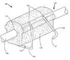
- FIG. 2is a schematic exterior perspective view of one embodiment of a lead anchor, according to the invention.
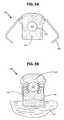
- FIG. 3Ais a schematic cross-sectional view of the lead anchor of FIG. 2 showing a fastener in the “open” position, prior to implantation;
- FIG. 3Bis a schematic cross-sectional view of the lead anchor of FIG. 2 showing a fastener in the “closed” position, after implantation;
- FIG. 4 Ais a schematic perspective view of a surgical crimping tool suitable for use according to the invention; the tool is depicted before implantation, when the fastener legs are open;
- FIG. 4 Bis a schematic perspective view of a surgical crimping tool suitable for use according to the invention; the tool is depicted after implantation, when the fastener legs are closed;
- FIG. 4Cis a blow-up view of the retention hook of the surgical crimping tool of FIGS. 4A and B;
- FIG. 5is a side view of the surgical crimping tool of FIGS. 4A and B.
- the present inventionis directed to the area of lead anchors used with implantable devices such as spinal cord stimulators, as well as methods of using lead anchors and implantable devices.
- the inventionis directed to a surgical crimping tool used to secure a lead anchor to a patients' tissue.
- a lead anchorcan be used in an implantable device, such as an implantable spinal cord stimulator, to anchor a lead connecting a control module to an electrode array.
- the leadpasses through the lead anchor, which is designed to prevent or reduce the likelihood that the lead will move within the lead anchor.
- the lead anchorapplies gentle compression to the lead to hold the lead in place.
- One embodimentis a lead anchor including a body defining a first opening and a second opening through which a lead can pass.
- One or more fastenersare attached to the body.
- the fastenersare used to attach the lead anchor to tissue at the intended stimulation site and may also provide a controlled compressive load against the lead, thereby gripping the lead to keep the lead in place and prevent migration of the lead away from the intended stimulation site.
- the two legs of the fastenersare initially spread apart on either side of the anchor. In a preferred embodiment, the legs have sharpened ends so they are capable of piercing tissue. For insertion, the lead is threaded through one opening of the anchor and out through the other opening.
- the anchoris attached to a patient's tissue by squeezing the exposed fastener ends into the tissue. In addition to locking the anchor in place, squeezing the exposed ends of the fastener together may also generate compression on the lead, gripping the lead to protect against lead migration.
- the anchor bodymay be made of any elastomeric material suitable for implantation into a patient's body.
- the materialis preferably compressible so as to compress against the lead when the fasteners are in the closed position.
- the bodyis made of silicone, polyurethane, or a combination thereof.
- the fastenerscan be any suitable component that can be configured and arranged to facilitate attachment of the lead anchor to surrounding tissue by squeezing ends of the fastener.
- the fasteneris a staple.
- the fastenersmay be made of any material that is suitable for implantation into a patient's body.
- the fastenersare made of any metal suitable for implantation into a patient's body.
- the fastenersare inserted through the anchor body such that the two legs of the fastener are spread apart on either side of the anchor prior to implantation.
- a portion of the fastenersis molded into the body when the body is formed.
- the exposed fastener endsmay be squeezed (i.e., closed) to attach the lead anchor to a patient's tissue with any suitable surgical tool.
- the fastenersare closed with a hemostat.
- the fastenersare closed with a surgical clamp.
- the fastenersare closed by squeezing the exposed ends of the fasteners together with a special surgical crimping tool provided with the lead anchor.
- the surgical crimping toolmay comprise a pair of handles fastened at a hinge element to form squeeze grips, and a retention hook, where the surgical crimping tool can squeeze together the exposed ends of the one or more surgical fasteners of a lead anchor, and the retention hook allows the surgical crimping tool to clear the lead and thus avoid damage to the lead.
- the special surgical crimping toolmay incorporate a travel stop to prevent over-crimping of the fasteners, which could damage the lead and/or the tissue to which the lead anchor is attached.
- the surgical crimping toolalso contains a retention hook upon which the lead anchor sits while attaching the fasteners to the tissue.
- the retention hookfacilitates proper spacing between the crimping tool and the lead anchor, so as to close the fasteners without damage to the lead or possible injury to the patient.
- the lead anchorprovides a constant lateral compression force between the fasteners, anchor body and lead.
- the hole in the anchor body through which the lead is threadedprovides a slight interference fit relative to the lead during the threading process. In other embodiments, the hole in the anchor body through which the lead is threaded is a clearance fit relative to the lead during the threading process.
- kitsthat contain one or more lead anchors and optionally a surgical crimping tool for attaching the lead anchor to a patient's tissue are provided.
- the kitcontains the entire implantable stimulation system or portions thereof, including one or more of a control module, an electrode array, a lead for coupling the control module to the electrode array, one or more lead anchors, and a surgical crimping tool for attaching the lead anchor to a patient's tissue.
- FIG. 1illustrates schematically an implantable stimulation device 100 , such as a spinal cord stimulator.
- the implantable stimulation deviceincludes a control module 102 , an electrode array 104 of stimulator electrodes, a lead 106 coupling the control module to the electrode array, and one or more lead anchors 108 .
- the control module 102typically includes a pulse generator that provides pulses of stimulation current to electrodes of the electrode array 104 .
- the control module 102may also include a power source for generating the stimulation current or may receive power from an external source.
- the power sourcecan be any available power source including batteries, such as primary batteries or rechargeable batteries.
- Examples of other power sourcesinclude, but are not limited to, super capacitors, nuclear or atomic batteries, mechanical resonators, infrared collectors, thermally-powered energy sources, flexural powered energy sources, bioenergy power sources, fuel cells, bioelectric cells, osmotic pressure pumps, and the like including the power sources described in U.S. Patent Application Publication No. 2004/0059392, incorporated herein by reference.
- the control module 102is optionally programmable to allowing programming of one or more functions such as, for example, the selection of electrodes for stimulation, the selection of electrodes as anode or cathode, the amplitude of the stimulation current, the duration of the stimulation current, and the periodicity of the stimulation current.
- the control module 102can be accessed using a programming unit external to the body of the patient to alter or modify these functions.
- the electrode array 104typically includes two or more electrodes. In some embodiments, the electrode array includes four, six, eight, 10, 16, or more electrodes.
- the electrodescan be in a linear array, for example, disposed along an electrode lead, or in a two-dimensional array, for example, forming two or more columns or rows, or any other arrangement. Non-limiting examples of suitable electrode arrays are illustrated in U.S. Pat. No. 6,516,227, incorporated herein by reference.
- Electrodes leads with electrode arraysinclude, for example, percutaneous leads, cuff leads, and paddle leads. Examples of stimulation systems with electrode leads are described in, for example, U.S. Pat. Nos. 6,181,969; 6,516,227; 6,609,029; 6,609,032; and 6,741,892; and U.S. patent application Ser. Nos. 11/238,240; 11/319,291; 11/327,880; 11/375,638; 11/393,991; and 11/396,309, all of which are incorporated herein by reference.
- the lead 106typically includes a set of conductors (for example, one conductor per electrode of the electrode array) within a non-conductive sheathing.
- the sheathingmay be made of a flexible, biocompatible material.
- FIGS. 2-3Billustrate one embodiment of a lead anchor 108 .
- the lead anchorincludes a body 120 that is open at two ends 122 , 124 to allow the lead 106 to pass through the lead anchor.
- the bodyhas one or more fasteners 126 and 128 attached to it.
- the body 120has two fasteners 126 .
- the fasteners 126are each inserted into the body 120 through holes 130 preferably in the top of the body, on the side opposite from where the lead anchor 108 is to be attached to a patient's tissue.
- the fastenercan be placed in other parts of the lead body as well.
- the fastenerscan be inserted so that the exposed legs of the fasteners run along two sides of the lead anchor 108 .
- the fastenerends with a pair of sharpened points 132 to facilitate piercing a patient's tissue.
- the front fastener 126is in the closed position with the exposed legs squeezed together, and the rear fastener 128 is in the open position with legs spread apart.
- FIG. 3Ashows the lead anchor 108 showing a fastener 126 in the “open” position, prior to implantation.
- FIG. 3Bshows the lead anchor 108 with a fastener 126 in the “closed” position, after attachment to a patient's tissue 134 .
- the anchor body 120can be formed using a plastic or elastomeric material.
- this materialis biocompatible, durable, and suitable for implantation in a patient over an expected period of time.
- the materialis preferably elastomeric and compressible. Examples of suitable materials include silicone and polyurethane.
- the anchor body 120can be formed using an available technique including, for example, molding techniques. Portions of the fastener may be molded into the body as illustrated in FIGS. 2 , 3 A, and 3 B.
- the length of the lead anchor 108can be selected for the particular purpose.
- the lead anchormay have a length in the range of 4 to 10 millimeters. This length may be shorter or longer than other available lead anchors, depending on the specific application.
- Lead anchors according to the inventionmay be secured to a subject patient's tissue by squeezing the exposed fastener ends towards each other and into the tissue by using a tool, e.g. a surgical clamp or hemostat.
- the lead anchoris secured by using a surgical crimping tool 136 according to the invention.
- FIGS. 4A-C and 5illustrate one embodiment of a surgical crimping tool 136 .
- the surgical crimping tool 136includes a pair of handles 138 fastened at a hinge element 140 to form squeeze grips 142 .
- the surgical crimping toolpreferably contains a travel stop 144 , to stop the crimping action of the surgical crimping tool 136 when the fastener 126 has been closed sufficiently to secure the lead anchor 108 to the patient's tissue and at the same time prevent damage to the lead 106 or the patient's tissue that may result from over-crimping.
- the surgical crimping tool 136also contains a retention hook 146 upon which the lead anchor can be placed. This positions the squeeze grips 142 relative to the fastener(s) 126 , so as to close the fasteners 126 without damaging the lead 106 and possible injury to the patient.
- the retention hook 146is attached or otherwise coupled to the pair of handles 138 (for example, coupled at the hinge element 140 as illustrated in FIGS. 4C and 5 ) and extends below the squeeze grips 142 to provide a platform upon which the lead anchor 108 can be placed while closing the fasteners, as illustrated in FIGS. 4B and 5 .
- the retention hook 146includes two parallel prongs with an opening between to allow the lead 106 to pass through the opening while the lead anchor 108 is sitting on the retention hook.
- a lead 106 of a stimulation device 100is threaded through a lead anchor 108 and the distal end of the lead incorporates, or is attached to, an array 104 of electrodes 148 located at the desired location within the patient being treated.
- FIG. 1illustrates schematically an implantable stimulation device 100 , such as a spinal cord stimulator.
- the other end of the lead 106is coupled to a control module 102 (or to a lead extension which is in turn coupled to the control module.)
- the medical practitioner or technicianlocates the lead anchor 108 to the desired area of attachment to the tissue 134 and uses a surgical crimping tool 136 or another suitable instrument to crimp the ends of the one or more fasteners 126 and 128 towards each other, thereby attaching the lead anchor 108 to the patient's tissue 134 .
- this entire procedurecan be completed in a fraction of the time needed to implant a stimulation device using conventional lead anchors. This procedure may also be less invasive than implantation procedures requiring the use of sutures and the like.
Landscapes
- Health & Medical Sciences (AREA)
- Neurology (AREA)
- Neurosurgery (AREA)
- Orthopedic Medicine & Surgery (AREA)
- Cardiology (AREA)
- Heart & Thoracic Surgery (AREA)
- Engineering & Computer Science (AREA)
- Biomedical Technology (AREA)
- Nuclear Medicine, Radiotherapy & Molecular Imaging (AREA)
- Radiology & Medical Imaging (AREA)
- Life Sciences & Earth Sciences (AREA)
- Animal Behavior & Ethology (AREA)
- General Health & Medical Sciences (AREA)
- Public Health (AREA)
- Veterinary Medicine (AREA)
- Electrotherapy Devices (AREA)
- Finger-Pressure Massage (AREA)
Abstract
Description
Claims (20)
Priority Applications (5)
| Application Number | Priority Date | Filing Date | Title |
|---|---|---|---|
| US11/692,772US7899553B2 (en) | 2007-03-28 | 2007-03-28 | Lead anchor for implantable stimulation devices |
| PCT/US2008/058426WO2008121708A2 (en) | 2007-03-28 | 2008-03-27 | Lead anchor for implantable stimulation devices |
| EP08744460AEP2139551A2 (en) | 2007-03-28 | 2008-03-27 | Lead anchor for implantable stimulation devices |
| AU2008232809AAU2008232809B2 (en) | 2007-03-28 | 2008-03-27 | Lead anchor for implantable stimulation devices |
| CA002681230ACA2681230A1 (en) | 2007-03-28 | 2008-03-27 | Lead anchor for implantable stimulation devices |
Applications Claiming Priority (1)
| Application Number | Priority Date | Filing Date | Title |
|---|---|---|---|
| US11/692,772US7899553B2 (en) | 2007-03-28 | 2007-03-28 | Lead anchor for implantable stimulation devices |
Publications (2)
| Publication Number | Publication Date |
|---|---|
| US20080243220A1 US20080243220A1 (en) | 2008-10-02 |
| US7899553B2true US7899553B2 (en) | 2011-03-01 |
Family
ID=39563364
Family Applications (1)
| Application Number | Title | Priority Date | Filing Date |
|---|---|---|---|
| US11/692,772Expired - Fee RelatedUS7899553B2 (en) | 2007-03-28 | 2007-03-28 | Lead anchor for implantable stimulation devices |
Country Status (5)
| Country | Link |
|---|---|
| US (1) | US7899553B2 (en) |
| EP (1) | EP2139551A2 (en) |
| AU (1) | AU2008232809B2 (en) |
| CA (1) | CA2681230A1 (en) |
| WO (1) | WO2008121708A2 (en) |
Cited By (7)
| Publication number | Priority date | Publication date | Assignee | Title |
|---|---|---|---|---|
| US20100069941A1 (en)* | 2008-09-15 | 2010-03-18 | Immersion Medical | Systems and Methods For Sensing Hand Motion By Measuring Remote Displacement |
| US8467883B2 (en) | 2009-07-21 | 2013-06-18 | Boston Scientific Neuromodulation Corporation | Spring passive lead anchor and methods and devices using the anchor |
| US8880189B2 (en) | 2011-02-23 | 2014-11-04 | John D. LIPANI | System and method for electrical stimulation of the lumbar vertebral column |
| US9204842B2 (en) | 2010-10-29 | 2015-12-08 | Medtronic, Inc. | Medical device fixation attachment mechanism |
| US9351648B2 (en) | 2012-08-24 | 2016-05-31 | Medtronic, Inc. | Implantable medical device electrode assembly |
| US20160166279A1 (en)* | 2014-12-11 | 2016-06-16 | Medtronic, Inc. | Apparatus and methods for tissue anchoring of medical devices |
| US9630011B2 (en) | 2011-02-23 | 2017-04-25 | John D Lipani | System and methods for diagnosis and treatment of discogenic lower back pain |
Families Citing this family (45)
| Publication number | Priority date | Publication date | Assignee | Title |
|---|---|---|---|---|
| US8019443B2 (en) | 2008-04-01 | 2011-09-13 | Boston Scientific Neuromodulation Corporation | Anchoring units for leads of implantable electric stimulation systems and methods of making and using |
| US9320891B2 (en)* | 2008-04-02 | 2016-04-26 | Boston Scientific Neuromodulation Corporation | Lead anchor for implantable devices and methods of manufacture and use |
| US9492655B2 (en)* | 2008-04-25 | 2016-11-15 | Boston Scientific Neuromodulation Corporation | Stimulation system with percutaneously deliverable paddle lead and methods of making and using |
| US8359107B2 (en)* | 2008-10-09 | 2013-01-22 | Boston Scientific Neuromodulation Corporation | Electrode design for leads of implantable electric stimulation systems and methods of making and using |
| US20100179626A1 (en)* | 2009-01-09 | 2010-07-15 | Medtronic, Inc. | System and method for implanting a paddle lead |
| US9887470B2 (en) | 2009-04-27 | 2018-02-06 | Boston Scienific Neuromodulation Corporation | Torque lock anchor and methods and devices using the anchor |
| US9352147B2 (en)* | 2009-04-27 | 2016-05-31 | Boston Scientific Neuromodulation Corporation | Torque lock anchor and methods and devices using the anchor |
| US8412349B2 (en)* | 2009-06-04 | 2013-04-02 | Boston Scientific Neuromodulation Corporation | Three-piece button anchor and methods and devices using the anchor |
| US8295948B2 (en)* | 2009-07-21 | 2012-10-23 | Boston Scientific Neuromodulation Corporation | Tubular lead anchor and methods and devices using the anchor |
| US8311643B2 (en)* | 2009-07-21 | 2012-11-13 | North Richard B | Spinal cord stimulation lead anchor |
| US20110264181A1 (en)* | 2010-04-27 | 2011-10-27 | Hamilton Dennison R | Spinal Cord Stimulator Lead Anchor |
| WO2012019052A2 (en) | 2010-08-04 | 2012-02-09 | Micardia Corporation | Percutaneous transcatheter repair of heart valves |
| US9402721B2 (en) | 2011-06-01 | 2016-08-02 | Valcare, Inc. | Percutaneous transcatheter repair of heart valves via trans-apical access |
| US9180008B2 (en) | 2012-02-29 | 2015-11-10 | Valcare, Inc. | Methods, devices, and systems for percutaneously anchoring annuloplasty rings |
| WO2013130641A1 (en) | 2012-02-29 | 2013-09-06 | Valcare, Inc. | Percutaneous annuloplasty system with anterior-posterior adjustment |
| US10786235B2 (en) | 2012-10-31 | 2020-09-29 | Anchor Innovation Medical, Inc. | Method and apparatus for closing a fissure in the annulus of an intervertebral disc, and/or for effecting other anatomical repairs and/or fixations |
| US10166100B2 (en) | 2013-03-15 | 2019-01-01 | Valcare, Inc. | Systems and methods for delivery of annuloplasty rings |
| US10813751B2 (en) | 2013-05-22 | 2020-10-27 | Valcare, Inc. | Transcatheter prosthetic valve for mitral or tricuspid valve replacement |
| US20160120642A1 (en) | 2013-05-24 | 2016-05-05 | Valcare, Inc. | Heart and peripheral vascular valve replacement in conjunction with a support ring |
| US11058417B2 (en) | 2013-06-28 | 2021-07-13 | Valcare, Inc. | Device, system, and method to secure an article to a tissue |
| CA2920546A1 (en) | 2013-08-16 | 2015-02-19 | Suture Concepts Inc. | Method and apparatus for closing a fissure in the annulus of an intervertebral disc, and/or for effecting other anatomical repairs and/or fixations |
| US9216563B2 (en) | 2013-08-19 | 2015-12-22 | Boston Scientific Neuromodulation Corporation | Lead anchor with adhesive and systems and methods using the lead anchor |
| US9517334B2 (en) | 2013-08-19 | 2016-12-13 | Boston Scientific Neuromodulation Corporation | Lead anchors and systems and methods employing the lead anchors |
| US9415212B2 (en) | 2014-02-28 | 2016-08-16 | Boston Scientific Neuromodulation Corporation | Side loading lead anchor and methods of making and using thereof |
| US9987482B2 (en) | 2014-05-27 | 2018-06-05 | Boston Scientific Neuromodulation Corporation | Systems and methods for making and using reversible mechanical lead anchors for electrical stimulation systems |
| US9636498B2 (en) | 2015-08-03 | 2017-05-02 | Boston Scientific Neuromodulation Corporation | Lead anchor with a wedge and systems using the lead anchor |
| WO2017151438A1 (en) | 2016-02-29 | 2017-09-08 | Boston Scientific Neuromodulation Corporation | Lead anchor for an electrical stimulation system |
| WO2017201058A1 (en) | 2016-05-17 | 2017-11-23 | Boston Scientific Neuromodulation Corporation | Systems and methods for anchoring a lead for neurostimulation of a target anatomy |
| CN107753153B (en) | 2016-08-15 | 2022-05-31 | 沃卡尔有限公司 | Device and method for treating heart valve insufficiency |
| US10709886B2 (en) | 2017-02-28 | 2020-07-14 | Boston Scientific Neuromodulation Corporation | Electrical stimulation leads and systems with elongate anchoring elements and methods of making and using |
| CN108618871A (en) | 2017-03-17 | 2018-10-09 | 沃卡尔有限公司 | Bicuspid valve with multi-direction anchor portion or tricuspid valve repair system |
| US10835739B2 (en) | 2017-03-24 | 2020-11-17 | Boston Scientific Neuromodulation Corporation | Electrical stimulation leads and systems with elongate anchoring elements and methods of making and using |
| US10857351B2 (en) | 2017-04-28 | 2020-12-08 | Boston Scientific Neuromodulation Corporation | Lead anchors for electrical stimulation leads and systems and methods of making and using |
| US11717674B2 (en) | 2018-07-31 | 2023-08-08 | Manicka Institute Llc | Subcutaneous device for use with remote device |
| US10576291B2 (en) | 2018-07-31 | 2020-03-03 | Manicka Institute Llc | Subcutaneous device |
| US10471251B1 (en) | 2018-07-31 | 2019-11-12 | Manicka Institute Llc | Subcutaneous device for monitoring and/or providing therapies |
| US11660444B2 (en) | 2018-07-31 | 2023-05-30 | Manicka Institute Llc | Resilient body component contact for a subcutaneous device |
| CN112546427B (en)* | 2018-07-31 | 2023-11-03 | 卡利安科技有限公司 | subcutaneous device |
| US10716511B2 (en) | 2018-07-31 | 2020-07-21 | Manicka Institute Llc | Subcutaneous device for monitoring and/or providing therapies |
| US11534300B2 (en) | 2018-12-03 | 2022-12-27 | Valcare, Inc. | Stabilizing and adjusting tool for controlling a minimally invasive mitral / tricuspid valve repair system |
| EP3982881B1 (en) | 2019-06-11 | 2025-04-16 | Valcare Medical, Inc. | Annuloplasty ring with posterior leaflet for minimally invasive treatment |
| US12396853B2 (en) | 2019-06-11 | 2025-08-26 | Valcare Medical, Inc. | Systems and methods for delivery of chordae replacement system |
| US11793628B2 (en) | 2019-07-15 | 2023-10-24 | Valcare, Inc. | Transcatheter bio-prosthesis member and support structure |
| US10987060B1 (en) | 2020-09-14 | 2021-04-27 | Calyan Technologies, Inc. | Clip design for a subcutaneous device |
| EP4333968A1 (en)* | 2021-05-05 | 2024-03-13 | BIOTRONIK SE & Co. KG | Anchoring holding tool |
Citations (36)
| Publication number | Priority date | Publication date | Assignee | Title |
|---|---|---|---|---|
| US4066085A (en)* | 1975-01-14 | 1978-01-03 | Cordis Corporation | Contact device for muscle stimulation |
| US4177818A (en)* | 1976-12-02 | 1979-12-11 | Pedro Francisco L De | Self attachable small-toothed electrode and a forceps for maneuvering it |
| US4553961A (en) | 1984-04-18 | 1985-11-19 | Cordis Corporation | Suture sleeve with structure for enhancing pacing lead gripping |
| US4672979A (en) | 1986-01-30 | 1987-06-16 | Cordis Corporation | Suture sleeve assembly |
| US4683895A (en)* | 1985-07-25 | 1987-08-04 | Cordis Corporation | Suture sleeve anchoring device |
| US4913164A (en)* | 1988-09-27 | 1990-04-03 | Intermedics, Inc. | Extensible passive fixation mechanism for lead assembly of an implantable cardiac stimulator |
| US5107856A (en) | 1991-01-10 | 1992-04-28 | Siemens-Pacesetter, Inc. | Multiple lead suture sleeve |
| US5242431A (en) | 1992-06-11 | 1993-09-07 | Siemens Pacesetter, Inc. | Suture sleeve assembly with slidable compression collar |
| US5525805A (en) | 1993-11-16 | 1996-06-11 | Sandia Corporation | Pulsed ion beam source |
| US5746722A (en) | 1997-02-05 | 1998-05-05 | Medtronic, Inc. | Suture sleeve with circumferential lead locking device |
| US5843146A (en) | 1997-04-30 | 1998-12-01 | Medtronic Incorporated | Adjustable medical lead anchor |
| US5931861A (en) | 1997-04-25 | 1999-08-03 | Medtronic, Inc. | Medical lead adaptor having rotatable locking clip mechanism |
| US5957968A (en) | 1997-09-26 | 1999-09-28 | Medtronic, Inc. | Suture sleeve with lead locking device |
| US6134447A (en) | 1998-05-29 | 2000-10-17 | Ericsson Inc. | System and method for monitoring and barring location applications |
| US6178356B1 (en)* | 1998-02-20 | 2001-01-23 | Cardiac Pacemakers, Inc. | Coronary venous lead having fixation mechanism |
| US6181969B1 (en) | 1998-06-26 | 2001-01-30 | Advanced Bionics Corporation | Programmable current output stimulus stage for implantable device |
| US6308104B1 (en) | 1996-02-20 | 2001-10-23 | Cardiothoracic Systems, Inc. | Method and apparatus for using vagus nerve stimulation in surgery |
| US6473654B1 (en) | 2000-03-08 | 2002-10-29 | Advanced Bionics Corporation | Lead anchor |
| US6516227B1 (en) | 1999-07-27 | 2003-02-04 | Advanced Bionics Corporation | Rechargeable spinal cord stimulator system |
| US6609032B1 (en) | 1999-01-07 | 2003-08-19 | Advanced Bionics Corporation | Fitting process for a neural stimulation system |
| US6609029B1 (en) | 2000-02-04 | 2003-08-19 | Advanced Bionics Corporation | Clip lock mechanism for retaining lead |
| US6610074B2 (en)* | 2000-02-10 | 2003-08-26 | Albert N. Santilli | Aorta cross clamp assembly |
| US20030212435A1 (en)* | 2002-03-26 | 2003-11-13 | Adam Gold | Handleless clamping device |
| US20040059392A1 (en) | 2002-06-28 | 2004-03-25 | Jordi Parramon | Microstimulator having self-contained power source |
| US6741892B1 (en) | 2000-03-10 | 2004-05-25 | Advanced Bionics Corporation | Movable contact locking mechanism for spinal cord stimulator lead connector |
| US20040199122A1 (en)* | 2000-08-03 | 2004-10-07 | Bierman Steven F. | Dialysis catheter anchoring system |
| US20040254623A1 (en)* | 2003-06-12 | 2004-12-16 | Cardiac Pacemakers, Inc. | Star suture sleeve |
| US20050004590A1 (en)* | 2003-07-01 | 2005-01-06 | Waters Amneris C. | Medical device to remove hubs/ends of intravenous tubing |
| US6901287B2 (en) | 2001-02-09 | 2005-05-31 | Medtronic, Inc. | Implantable therapy delivery element adjustable anchor |
| US6951550B2 (en)* | 1998-03-27 | 2005-10-04 | Venetec International, Inc. | Anchoring system for a medical article |
| US20060161237A1 (en)* | 2005-01-14 | 2006-07-20 | Cardiac Pacemakers, Inc. | Fastening device for an epicardial lead |
| US20070150007A1 (en) | 2005-12-27 | 2007-06-28 | Advanced Bionics Corporation | Non-linear electrode array |
| US20070150036A1 (en) | 2005-12-27 | 2007-06-28 | Advanced Bionics Corporation | Stimulator leads and methods for lead fabrication |
| US7244150B1 (en) | 2006-01-09 | 2007-07-17 | Advanced Bionics Corporation | Connector and methods of fabrication |
| US20070219595A1 (en) | 2006-03-14 | 2007-09-20 | Advanced Bionics Corporation | Stimulator system with electrode array and the method of making the same |
| US20070239243A1 (en) | 2006-03-30 | 2007-10-11 | Advanced Bionics Corporation | Electrode contact configurations for cuff leads |
- 2007
- 2007-03-28USUS11/692,772patent/US7899553B2/ennot_activeExpired - Fee Related
- 2008
- 2008-03-27EPEP08744460Apatent/EP2139551A2/ennot_activeWithdrawn
- 2008-03-27AUAU2008232809Apatent/AU2008232809B2/ennot_activeExpired - Fee Related
- 2008-03-27CACA002681230Apatent/CA2681230A1/ennot_activeAbandoned
- 2008-03-27WOPCT/US2008/058426patent/WO2008121708A2/enactiveApplication Filing
Patent Citations (36)
| Publication number | Priority date | Publication date | Assignee | Title |
|---|---|---|---|---|
| US4066085A (en)* | 1975-01-14 | 1978-01-03 | Cordis Corporation | Contact device for muscle stimulation |
| US4177818A (en)* | 1976-12-02 | 1979-12-11 | Pedro Francisco L De | Self attachable small-toothed electrode and a forceps for maneuvering it |
| US4553961A (en) | 1984-04-18 | 1985-11-19 | Cordis Corporation | Suture sleeve with structure for enhancing pacing lead gripping |
| US4683895A (en)* | 1985-07-25 | 1987-08-04 | Cordis Corporation | Suture sleeve anchoring device |
| US4672979A (en) | 1986-01-30 | 1987-06-16 | Cordis Corporation | Suture sleeve assembly |
| US4913164A (en)* | 1988-09-27 | 1990-04-03 | Intermedics, Inc. | Extensible passive fixation mechanism for lead assembly of an implantable cardiac stimulator |
| US5107856A (en) | 1991-01-10 | 1992-04-28 | Siemens-Pacesetter, Inc. | Multiple lead suture sleeve |
| US5242431A (en) | 1992-06-11 | 1993-09-07 | Siemens Pacesetter, Inc. | Suture sleeve assembly with slidable compression collar |
| US5525805A (en) | 1993-11-16 | 1996-06-11 | Sandia Corporation | Pulsed ion beam source |
| US6308104B1 (en) | 1996-02-20 | 2001-10-23 | Cardiothoracic Systems, Inc. | Method and apparatus for using vagus nerve stimulation in surgery |
| US5746722A (en) | 1997-02-05 | 1998-05-05 | Medtronic, Inc. | Suture sleeve with circumferential lead locking device |
| US5931861A (en) | 1997-04-25 | 1999-08-03 | Medtronic, Inc. | Medical lead adaptor having rotatable locking clip mechanism |
| US5843146A (en) | 1997-04-30 | 1998-12-01 | Medtronic Incorporated | Adjustable medical lead anchor |
| US5957968A (en) | 1997-09-26 | 1999-09-28 | Medtronic, Inc. | Suture sleeve with lead locking device |
| US6178356B1 (en)* | 1998-02-20 | 2001-01-23 | Cardiac Pacemakers, Inc. | Coronary venous lead having fixation mechanism |
| US6951550B2 (en)* | 1998-03-27 | 2005-10-04 | Venetec International, Inc. | Anchoring system for a medical article |
| US6134447A (en) | 1998-05-29 | 2000-10-17 | Ericsson Inc. | System and method for monitoring and barring location applications |
| US6181969B1 (en) | 1998-06-26 | 2001-01-30 | Advanced Bionics Corporation | Programmable current output stimulus stage for implantable device |
| US6609032B1 (en) | 1999-01-07 | 2003-08-19 | Advanced Bionics Corporation | Fitting process for a neural stimulation system |
| US6516227B1 (en) | 1999-07-27 | 2003-02-04 | Advanced Bionics Corporation | Rechargeable spinal cord stimulator system |
| US6609029B1 (en) | 2000-02-04 | 2003-08-19 | Advanced Bionics Corporation | Clip lock mechanism for retaining lead |
| US6610074B2 (en)* | 2000-02-10 | 2003-08-26 | Albert N. Santilli | Aorta cross clamp assembly |
| US6473654B1 (en) | 2000-03-08 | 2002-10-29 | Advanced Bionics Corporation | Lead anchor |
| US6741892B1 (en) | 2000-03-10 | 2004-05-25 | Advanced Bionics Corporation | Movable contact locking mechanism for spinal cord stimulator lead connector |
| US20040199122A1 (en)* | 2000-08-03 | 2004-10-07 | Bierman Steven F. | Dialysis catheter anchoring system |
| US6901287B2 (en) | 2001-02-09 | 2005-05-31 | Medtronic, Inc. | Implantable therapy delivery element adjustable anchor |
| US20030212435A1 (en)* | 2002-03-26 | 2003-11-13 | Adam Gold | Handleless clamping device |
| US20040059392A1 (en) | 2002-06-28 | 2004-03-25 | Jordi Parramon | Microstimulator having self-contained power source |
| US20040254623A1 (en)* | 2003-06-12 | 2004-12-16 | Cardiac Pacemakers, Inc. | Star suture sleeve |
| US20050004590A1 (en)* | 2003-07-01 | 2005-01-06 | Waters Amneris C. | Medical device to remove hubs/ends of intravenous tubing |
| US20060161237A1 (en)* | 2005-01-14 | 2006-07-20 | Cardiac Pacemakers, Inc. | Fastening device for an epicardial lead |
| US20070150007A1 (en) | 2005-12-27 | 2007-06-28 | Advanced Bionics Corporation | Non-linear electrode array |
| US20070150036A1 (en) | 2005-12-27 | 2007-06-28 | Advanced Bionics Corporation | Stimulator leads and methods for lead fabrication |
| US7244150B1 (en) | 2006-01-09 | 2007-07-17 | Advanced Bionics Corporation | Connector and methods of fabrication |
| US20070219595A1 (en) | 2006-03-14 | 2007-09-20 | Advanced Bionics Corporation | Stimulator system with electrode array and the method of making the same |
| US20070239243A1 (en) | 2006-03-30 | 2007-10-11 | Advanced Bionics Corporation | Electrode contact configurations for cuff leads |
Non-Patent Citations (2)
| Title |
|---|
| Compact Oxford English Dictionary (Definition: "pin").* |
| U.S. Appl. No. 11/238,240, filed Sep. 29, 2005. |
Cited By (13)
| Publication number | Priority date | Publication date | Assignee | Title |
|---|---|---|---|---|
| US9679499B2 (en)* | 2008-09-15 | 2017-06-13 | Immersion Medical, Inc. | Systems and methods for sensing hand motion by measuring remote displacement |
| US20100069941A1 (en)* | 2008-09-15 | 2010-03-18 | Immersion Medical | Systems and Methods For Sensing Hand Motion By Measuring Remote Displacement |
| US8467883B2 (en) | 2009-07-21 | 2013-06-18 | Boston Scientific Neuromodulation Corporation | Spring passive lead anchor and methods and devices using the anchor |
| US10307601B2 (en) | 2010-10-29 | 2019-06-04 | Medtronic, Inc. | Attachment mechanism for a fixation member of an implantable device |
| US9204842B2 (en) | 2010-10-29 | 2015-12-08 | Medtronic, Inc. | Medical device fixation attachment mechanism |
| US9789313B2 (en) | 2011-02-23 | 2017-10-17 | John D. LIPANI | System and methods for diagnosis and treatment of discogenic lower back pain |
| US9630011B2 (en) | 2011-02-23 | 2017-04-25 | John D Lipani | System and methods for diagnosis and treatment of discogenic lower back pain |
| US8892215B2 (en) | 2011-02-23 | 2014-11-18 | John D. LIPANI | System and method for electrical stimulation of the lumbar vertebral column |
| US9950164B2 (en) | 2011-02-23 | 2018-04-24 | John D Lipani | System and methods for diagnosis and treatment of discogenic lower back pain |
| US8880189B2 (en) | 2011-02-23 | 2014-11-04 | John D. LIPANI | System and method for electrical stimulation of the lumbar vertebral column |
| US9351648B2 (en) | 2012-08-24 | 2016-05-31 | Medtronic, Inc. | Implantable medical device electrode assembly |
| US20160166279A1 (en)* | 2014-12-11 | 2016-06-16 | Medtronic, Inc. | Apparatus and methods for tissue anchoring of medical devices |
| US10112042B2 (en)* | 2014-12-11 | 2018-10-30 | Medtronic, Inc. | Apparatus and methods for tissue anchoring of medical devices |
Also Published As
| Publication number | Publication date |
|---|---|
| CA2681230A1 (en) | 2008-10-09 |
| AU2008232809B2 (en) | 2013-08-15 |
| EP2139551A2 (en) | 2010-01-06 |
| US20080243220A1 (en) | 2008-10-02 |
| WO2008121708A2 (en) | 2008-10-09 |
| AU2008232809A1 (en) | 2008-10-09 |
| WO2008121708A3 (en) | 2008-12-24 |
Similar Documents
| Publication | Publication Date | Title |
|---|---|---|
| US7899553B2 (en) | Lead anchor for implantable stimulation devices | |
| US7831313B2 (en) | Lead anchor for implantable stimulation devices and methods of manufacture and use | |
| EP2429632B1 (en) | Torque lock anchor and methods and devices using the anchor | |
| US10159833B2 (en) | Torque lock anchor and methods and devices using the anchor | |
| US8768488B2 (en) | Systems and methods for electrically stimulating patient tissue on or around one or more bony structures | |
| US20120185027A1 (en) | Torque lock anchor and methods and devices using the anchor | |
| US9517334B2 (en) | Lead anchors and systems and methods employing the lead anchors | |
| EP1048321A2 (en) | Single and multi-polar implantable lead for sacral nerve electrical stimulation | |
| US20120150202A1 (en) | Devices containing a suture sleeve and methods of making and using | |
| CN103889502A (en) | Device for anchoring an electrode lead for use with an implantable neuromuscular electrical stimulator | |
| US20110288618A1 (en) | Neurostimulation lead anchors | |
| US20110264180A1 (en) | Spinal cord stimulator lead anchor | |
| US20110264181A1 (en) | Spinal Cord Stimulator Lead Anchor | |
| AU2016200306B2 (en) | Torque lock anchor and methods and devices using the anchor |
Legal Events
| Date | Code | Title | Description |
|---|---|---|---|
| AS | Assignment | Owner name:ADVANCED BIONICS CORPORATION, CALIFORNIA Free format text:ASSIGNMENT OF ASSIGNORS INTEREST;ASSIGNOR:BARKER, JOHN M.;REEL/FRAME:019103/0343 Effective date:20070327 | |
| AS | Assignment | Owner name:BOSTON SCIENTIFIC NEUROMODULATION CORPORATION, CAL Free format text:CHANGE OF NAME;ASSIGNOR:ADVANCED BIONICS CORPORATION;REEL/FRAME:020296/0477 Effective date:20071116 Owner name:BOSTON SCIENTIFIC NEUROMODULATION CORPORATION, CALIFORNIA Free format text:CHANGE OF NAME;ASSIGNOR:ADVANCED BIONICS CORPORATION;REEL/FRAME:020296/0477 Effective date:20071116 Owner name:BOSTON SCIENTIFIC NEUROMODULATION CORPORATION,CALI Free format text:CHANGE OF NAME;ASSIGNOR:ADVANCED BIONICS CORPORATION;REEL/FRAME:020296/0477 Effective date:20071116 | |
| AS | Assignment | Owner name:BOSTON SCIENTIFIC NEUROMODULATION CORPORATION, CAL Free format text:CHANGE OF NAME;ASSIGNOR:ADVANCED BIONICS CORPORATION;REEL/FRAME:020405/0722 Effective date:20071116 Owner name:BOSTON SCIENTIFIC NEUROMODULATION CORPORATION,CALI Free format text:CHANGE OF NAME;ASSIGNOR:ADVANCED BIONICS CORPORATION;REEL/FRAME:020405/0722 Effective date:20071116 | |
| REMI | Maintenance fee reminder mailed | ||
| LAPS | Lapse for failure to pay maintenance fees | ||
| STCH | Information on status: patent discontinuation | Free format text:PATENT EXPIRED DUE TO NONPAYMENT OF MAINTENANCE FEES UNDER 37 CFR 1.362 | |
| FP | Lapsed due to failure to pay maintenance fee | Effective date:20150301 |