US7896902B2 - Multi-axial double locking bone screw assembly - Google Patents
Multi-axial double locking bone screw assemblyDownload PDFInfo
- Publication number
- US7896902B2 US7896902B2US11/648,983US64898307AUS7896902B2US 7896902 B2US7896902 B2US 7896902B2US 64898307 AUS64898307 AUS 64898307AUS 7896902 B2US7896902 B2US 7896902B2
- Authority
- US
- United States
- Prior art keywords
- bone anchor
- assembly
- polar
- receiver
- opening
- Prior art date
- Legal status (The legal status is an assumption and is not a legal conclusion. Google has not performed a legal analysis and makes no representation as to the accuracy of the status listed.)
- Expired - Fee Related, expires
Links
Images


Classifications
- A—HUMAN NECESSITIES
- A61—MEDICAL OR VETERINARY SCIENCE; HYGIENE
- A61B—DIAGNOSIS; SURGERY; IDENTIFICATION
- A61B17/00—Surgical instruments, devices or methods
- A61B17/56—Surgical instruments or methods for treatment of bones or joints; Devices specially adapted therefor
- A61B17/58—Surgical instruments or methods for treatment of bones or joints; Devices specially adapted therefor for osteosynthesis, e.g. bone plates, screws or setting implements
- A61B17/68—Internal fixation devices, including fasteners and spinal fixators, even if a part thereof projects from the skin
- A61B17/70—Spinal positioners or stabilisers, e.g. stabilisers comprising fluid filler in an implant
- A61B17/7001—Screws or hooks combined with longitudinal elements which do not contact vertebrae
- A61B17/7032—Screws or hooks with U-shaped head or back through which longitudinal rods pass
- A—HUMAN NECESSITIES
- A61—MEDICAL OR VETERINARY SCIENCE; HYGIENE
- A61B—DIAGNOSIS; SURGERY; IDENTIFICATION
- A61B17/00—Surgical instruments, devices or methods
- A61B17/56—Surgical instruments or methods for treatment of bones or joints; Devices specially adapted therefor
- A61B17/58—Surgical instruments or methods for treatment of bones or joints; Devices specially adapted therefor for osteosynthesis, e.g. bone plates, screws or setting implements
- A61B17/68—Internal fixation devices, including fasteners and spinal fixators, even if a part thereof projects from the skin
- A61B17/70—Spinal positioners or stabilisers, e.g. stabilisers comprising fluid filler in an implant
- A61B17/7001—Screws or hooks combined with longitudinal elements which do not contact vertebrae
- A61B17/7035—Screws or hooks, wherein a rod-clamping part and a bone-anchoring part can pivot relative to each other
- A61B17/7037—Screws or hooks, wherein a rod-clamping part and a bone-anchoring part can pivot relative to each other wherein pivoting is blocked when the rod is clamped
Definitions
- the present inventionrelates to devices and implants used in osteosynthesis and other orthopedic surgical procedures such as devices for use in spinal surgery, and, in particular, to an posterior pedicle screw, connector/rod assembly which is implantable within a patient for stabilization of the spine.
- the present inventionrelates to a top loading bone anchor assembly capable of achieving multiple angular axial orientations with respect to an elongated member extending along bone tissue.
- an elongated membersuch as a bendable rod is disposed longitudinally along a length of the bone(s).
- the rodis preferably bent to correspond to the normal curvature of the spine in the particular region being instrumented.
- the rodcan be bent to form a normal kyphotic curvature for the thoracic region of the spine, or a lordotic curvature for the lumbar region.
- the rodis engaged to various vertebrae along a length of the spinal column by way of a number of fixation elements.
- fixation elementscan be provided which are configured to engage specific portions of the vertebra and other bones.
- one such fixation elementis a hook which is configured to engage the laminae of the vertebra.
- Another very prevalent fixation elementis a screw that can be threaded into various parts of the vertebrae or other bones.
- the rodis situated on opposite sides of the spine or spinous processes.
- a plurality of bone screwsare threaded into a portion of several vertebral bodies, very frequently into the pedicles of these vertebrae.
- the rodsare affixed to this plurality of bone screws to apply corrective and stabilizing forces to the spine.
- a rod-type spinal fixation systemincludes elongated rods and a variety of hooks, screws, and bolts, all configured to create a segmental construct throughout the spine.
- the spinal rodis connected to the various vertebral fixation elements using eyebolts.
- the fixation elementsare engaged to the spinal rod laterally adjacent to the rod.
- a variable angle screwmay be engaged to the spinal rod with an eyebolt. The variable angle screw allows pivoting of the bone screw in a single plane parallel to the plane of the spinal rod. Details of this type of system can be found in U.S. Pat. No. 5,261,909 to Sutterlin et al., the disclosure of which is incorporated by reference herein.
- This type of systemallows a surgeon to apply vertebral fixation elements, such as a spinal hook or a bone screw, to the spine in appropriate anatomic positions and also allows the surgeon to easily engage a bent spinal rod to each of the fixation elements for final tightening.
- fixation elementsfor engagement between an elongated rod and the spine.
- the fixation elementsthemselves include a body that defines a slot within which the spinal rod is received.
- the slotincludes a threaded bore into which a threaded plug is engaged to clamp the rod within the body of the fixation element.
- the systemuses hooks and bone screws having this “open-back” configuration. Details of this type of system can be found in U.S. Pat. No. 5,005,562, the disclosure of which is incorporated by reference herein.
- fixation elements of these types of systemsare capable only of pivoting about the spinal rod to achieve variable angular positions relative to the rod. While this limited range of relative angular positioning may be acceptable for many spinal pathologies, many other cases require more creative orientation of a fixation element (such as a bone screw relative) to a spinal rod. While certain aspects of this problem may be addressed by the variable angle screw of the '909 patent type of system, there remains a need for a bone screw capable of angular orientation in multiple planes relative to the spinal rod, as well as multiple spherical head orientations.
- the bone screw axisis capable of various three dimensional orientations with respect to the spinal rod.
- Screws of this type of angular orientation in multiple planes relative to the spinal rodhave been referred to as poly-axial or multi-axial bone screws.
- the use of both angular orientations in multiple planes relative to the spinal rodallows for virtually unlimited axial angulations of the bone engaging screw member within the design parameters as well as an ultra-low profile of the said device utilizing a minimum of components without sacrificing the security of the interfaces of the invention components.
- Conical nuts on opposite sides of the receiver memberare threaded onto a threaded rod passing through the receiver.
- the receiver memberflexibly compresses around the head of the bone screw to clamp the bone screw in its variable angular position.
- One detriment of the systems in the two Harms et al. patentsis that the spinal rod must be threaded in order to accept the compression nuts. It is known that threading rods can tend to weaken the rods in the face of severe spinal loads.
- the design of the bone screws in these patentsrequires a multiplicity of parts, which makes it fairly complicated to achieve complete fixation of the bone screw.
- a further approachis illustrated in U.S. Pat. No. 5,797,911 to Sherman et al., the disclosure of which is incorporated by reference herein.
- a U-shaped holderis provided, through the top of which a bone fastener topped with a crown member is loaded.
- the holderaccommodates a rod in a channel above the crown member and a compression member above the rod.
- the compression memberpresses on the rod and crown member to lock the fastener against the holder in any of a number of angles in three dimensions with respect to the rod.
- This approachhas proven to be quite effective in addressing the above-identified problems. However, it does not permit bottom-loading of the fastener. Additionally, the holder is somewhat bulky in order to accommodate the other structural components.
- the present inventionincludes a top-loading multi-axial, double locking bone anchor system or assembly.
- a receiver memberreceives an internal saddle member, a bi-polar member, and a bone anchor through an open bottom, which are retained by an internal threaded ring member threaded onto the receiver member.
- a double-locking compression retaining memberincludes an external nut-like fastener and an internal setscrew-like fastener. The nut-like fastener attaches to an upper portion of the receiver member and interfaces with the internal saddle member to retain a desired angular position on the bone anchor and the setscrew-like fastener interfaces with an elongated member placed in a channel of the receiver member to retain it to the assembly.
- the apposing forces created by these fastenerscreate a locking force within the double-locking compression retaining member thus reducing the likelihood of involuntary loosening of the double-locking compression retainer member.
- the bone anchoris capable of multi-axial as well as multi-polar positioning with respect to the receiver member.
- FIG. 1is a partial sectional side elevational view of one illustrative embodiment of the multi-axial, double-locking bone screw anchor assembly in accordance with the present invention.
- FIG. 2is an exploded partial sectional view of the assembly depicted in FIG. 1 .
- FIG. 3 ais a side elevational view of an embodiment of the receiver member of the assembly illustrated in FIGS. 1 and 2 .
- FIG. 3 bis a front elevational view of the embodiment of the receiver member illustrated in FIG. 3 a.
- FIG. 3 cis a sectional view, taken along the line 3 c - 3 c in FIG. 3 a , and viewed in the direction of the arrows, of the embodiment of the receiver member illustrated in FIG. 3 a.
- FIG. 3 dis a sectional view, taken along the lines 3 d - 3 d of FIG. 3 b and viewed in the direction of the arrows, of the embodiment of the receiver member illustrated in FIG. 3 a.
- FIG. 4 ais a side elevational view of an embodiment of a bone anchor used in the assembly illustrated in FIGS. 1 and 2 .
- FIG. 4 bis a sectional view, taken along the lines 4 b - 4 b of FIG. 4 a and viewed in the direction of the arrows, of the embodiment of the bone anchor illustrated in FIG. 4 a.
- FIG. 4 cis a magnified view of one embodiment of the head of the bone anchor illustrated in FIG. 4 a.
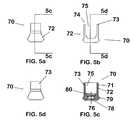
- FIG. 5 ais a side view of one embodiment of an internal saddle member which may be used in the assembly illustrated in FIGS. 1 and 2 .
- FIG. 5 bis a front view of the embodiment of an internal saddle member illustrated in FIG. 5 a.
- FIG. 5 cis a sectional view, taken along the lines 5 c - 5 c in FIG. 5 a and viewed in the direction of the arrows, of the embodiment of the internal saddle member illustrated in FIG. 5 a.
- FIG. 5 dis a sectional view, taken along the lines 5 d - 5 d in FIG. 5 b and viewed in the direction of the arrows, of the embodiment of the internal saddle member illustrated in FIG. 5 a.
- FIG. 6 ais a top view of one embodiment of an internal threaded ring member that fits around the bone anchor and over the outer lower threaded portion in the receiver member to retain the internal saddle member and the bone anchor member used in the assembly illustrated in FIGS. 1 and 2 .
- FIG. 6 bis a sectional view, taken along the lines of 6 b - 6 b in FIG. 6 a and viewed in the direction of the arrows, of the embodiment of the internal threaded ring member illustrated in FIG. 6 a.
- FIG. 7 ais a top view of one embodiment of a retaining member used in the assembly illustrated in FIGS. 1 and 2 .
- FIG. 7 bis a side elevational view of the retaining member illustrated in FIG. 7 a.
- FIG. 7 cis a bottom view of the retaining member illustrated in FIG. 7 a.
- FIG. 7 dis a sectional view of the retaining member illustrated in FIG. 7 a , taken along the lines 7 d - 7 d in FIG. 7 a and viewed in the direction of the arrows.
- FIG. 8 ais a top view of one embodiment of a bi-polar member used in the assembly illustrated in FIGS. 1 and 2 .
- FIG. 8 bis a sectional view, taken along the line 8 b - 8 b in FIG. 8 a and viewed in the direction of the arrows, of the bi-polar member illustrated in FIG. 8 a.
- FIG. 8 cis a sectional view substantially similar to FIG. 8 b of another embodiment of a bi-polar member which may be used with assemblies in accordance with the present invention.
- FIG. 9is an enlarged sectional view of the assembly illustrated in FIGS. 1 and 2 .
- assembly 20includes a receiver member 30 , a bone anchor 50 , an internal saddle member 70 , a bi-polar member 101 , an internal threaded ring member 90 , and a retainer assembly 120 .
- the assembly 20 of the present inventionis designed for use with an elongated member R, such as a spinal rod, bar or other orthopedic construct.
- Receiver member 30is a generally circular member having at least one sidewall 37 surrounding a central aperture 32 .
- Sidewall 33defines an upper portion 31 a and a lower portion 31 b of the receiver 30 .
- Central aperture 32extends through receiver member 30 from an upper aperture 33 in top end 34 of upper portion 31 a to a lower aperture 35 in bottom end 36 of lower portion 31 b .
- Central aperture 32may include, in one specific embodiment, a chamber/void 38 defined by a chamber wall 39 in lower portion of receiver 30 .
- the diameter of the central aperture 32 at chamber/void 38is larger than the diameter of the central aperture 32 in upper portion 31 a .
- the upper and lower portions 31 a , 31 bcan have a variety of configurations, such as each having one or more sections of differing diameter.
- Receiver member 30may have a chamfered or rounded edge 40 a at top end 34 , and may have a surrounding chamfered or rounded edge 40 b at the bottom end 36 .
- the exterior surface of the receive member 30may include threads 41 and an associated ledge 41 a around sidewall 37 .
- threads 41extend around the entire perimeter of lower surface 32 , although it will be appreciated that threads 41 could extend only partially around the perimeter of lower surface 32 .
- Thread 41has a thread depth A ( FIG. 9 ) and a thread diameter B ( FIG. 3 a ).
- Receiver member 30may include one or more pairs of upright branches 42 , 43 in upper portion 31 a , through which central aperture 32 extends. Branches 42 , 43 may further define a generally U-shaped channel 45 transverse to opening 32 that communicates with upper portion 31 a and lower portion 31 b of opening 32 , and that accommodates an elongated member R ( FIG. 9 ).
- external threads 44are formed in branches 42 , 43 , and may be a modified acme buttress thread.
- the width 47 of upper portion 31 a of receiver member 30(which includes branches 42 , 43 ) may be narrower than the width 48 of bottom portion 31 b of receiver member 30 , thereby reducing the bulk and profile of receiver member 30 .
- Bone anchor 50is a bone screw.
- Bone anchor 50includes an anchorage portion 52 and a head portion 54 .
- anchorage portion 52includes at least one thread 56 , which may be a cancellous self-tapping thread, around an elongated shaft.
- Head portion 54is disposed at a proximal end of the shaft and has a curvate cross-sectional shape. As illustrated, this curvate shape may form a portion of a sphere, though alternative curvate and other configurations may be employed.
- Head 54may include structures for improving purchase with the surrounding members of system 20 .
- head 54may feature a series of ridges 58 for improving purchase with the lower inside of internal saddle member 70 (described below), or may have alternative friction-increasing surface configurations, such as roughening or knurling.
- head 54may include a tool-engaging print 60 (not shown) with which a tool (not shown) may be engaged to drive anchorage portion 52 into a bone.
- Tool-engaging print 60may be an interior print or an exterior print, and it may have any of a number of configurations, such as hexagonal, hexalobate, X-shaped, or other known torque-transferring configurations.
- bone anchor 50with a suitable head 54 may be used in systems in accordance with the principles of the present invention.
- bone anchor 50could be a bone-engaging hook rather than a screw.
- anchorage portion 52would be configured with a hook rather than an elongated section with thread 56 .
- Head 54 of bone anchor 50may be shaped and sized to fit within at least interior portion 78 of internal saddle member 70 ( FIG. 1 and FIGS. 5 a - 5 d ) and chamber 38 of receiver member 30 . Specifically, head 54 may have a width that is smaller than the width of lower aperture 35 and chamber 38 of receiver member 30 . As more fully described below, bone anchor 50 may be inserted into receiver member 30 , with anchorage portion 50 entering through opening 80 and interfacing with surface 78 of internal saddle member 70 or 70 A.
- Internal saddle member 70may be generally shaped as a hollow cylinder, having an exterior surface 72 with a beveled top edge 74 surrounding a central channel 76 which runs from top edge 74 to a bottom opening.
- the central channel 76includes an enlarged portion 77 sized to retain at least a portion of head 54 of a bone anchor 50 near the bottom opening.
- the enlarged portion 77may taper from a narrower top to a wider bottom near the bottom opening, generally mirroring the portion of the head 54 of bone anchor 50 .
- the illustrated embodiment of enlarged portion 77has the shape of part of a sphere.
- the interior surface 78 of enlarged portion 77may be provided with a friction or purchase enhancing surface configuration for cooperation with head 54 of bone anchor 50 .
- the interior surface 78has ridges or steps 80 in the enlarged portion 77 .
- the surface 78may be roughened or knurled.
- a screw driving toolcan access the bone anchor 50 through central channel 76 , in order to drive the bone anchor 50 .
- Internal saddle member 70is sized and shaped to fit receiver member 30 by loading through lower aperture 35 and chamber 38 .
- the outer dimension of the lower portion of internal saddle member 70may be slightly smaller than the inner dimension of chamber 38 so the saddle member 70 is slidably movable within chamber 38 and opening 32 .
- the outer dimension of the lower potion of the internal saddle member 70is larger than the inner dimension of central aperture 32 in the upper portion 31 a , so that internal saddle member 70 cannot move into upper portion 31 a . As depicted, this may be accomplished by an external shelf 79 on the outer surface of the lower portion of saddle member 70 .
- sidewall 71defines two or more pairs of branches 72 and 73 , through which central channel 76 extends.
- Branches 72 , 73may further define one or more generally U-shaped transverse channels 75 , which run generally perpendicularly to central channel 76 to accommodate an elongated member R ( FIG. 9 ).
- transverse channel 75may align with U-shaped channel 45 to allow for the top loading of the elongated member R.
- the interior surface of the transverse channel 75may be provided with a friction or purchase enhancing surface configuration for cooperation with an elongated member R. As depicted, the interior surface of transverse channel 75 may have ridges or steps, or it may be roughened or knurled.
- bi-polar member 101is formed as a circular disc, having an exterior surface 102 with a top edge 104 and an interior surface 108 .
- Interior surface 108is configured to accommodate head 54 of bone anchor 50 .
- the illustrated embodiment of interior surface 108 in FIGS. 8A and 8Bhas the shape of part of a sphere. It will be appreciated that in other embodiments, the shape may differ, in order to accommodate other head 54 shapes. For example, see the conical interior surface 108 ′ of FIG. 8C .
- Interior surface 108can be provided with a friction or purchase-enhancing surface configuration (e.g. roughening or knurling) for cooperation with head 54 of bone anchor 50 .
- Bi-polar member 101also includes a hole 110 faced by interior surface 108 .
- Hole 110is provided so that bone anchor 50 may be partially passed therethrough, allowing the bone engaging threads 56 of bone anchor 50 to be available through bi-polar member 101 , while head 54 is retained therein.
- the dimension of hole 110 of the bi-polar member 101is preferably slightly larger than the outer dimension of bone anchor head 54 so that the bone anchor head 54 is slidably and rotatably movable within hole 110 and bipolar member 101 .
- Bi-polar member 101is sized and shaped to fit within at least lower portion 31 b of central aperture 32 and chamber 38 of receiver member 30 .
- the outer dimension of bi-polar member 101is preferably slightly smaller than the inner dimension of chamber 38 and lower portion 31 b of central aperture 32 so that bi-polar member 101 is slidably and rotatably movable within chamber 38 and central aperture 32 . Further, in the illustrated embodiment, the outer dimension of bi-polar member 101 is larger than the inner dimension of upper opening portion 31 a , so that bi-polar member 101 cannot move into upper portion 31 a of receiver member 30 .
- internal threaded ring member 90is a generally ring-shaped member with a central aperture 94 .
- Internal threaded ring member 90includes a top surface 92 and a bottom surface 93 .
- An internal surface 96 of sidewall 98substantially surrounds central aperture 94 .
- internal surface 96forms a portion of a sphere of radius substantially identical to the radius of head 54 of bone anchor 50 near bottom opening 102 of aperture 94 .
- the internal surface 96is conical and angled outward at angle 100 to allow a greater range of angular positioning of bone anchor 50 .
- there may be single or multiple internal angles to the internal surface 96 in the lower portion of aperture 94 near bottom opening 102such that internal surface 96 may have portions with a cylindrical, conical, spherical or of other appropriate configuration.
- the diameter of bottom opening 102is smaller than the diameter of head 54 of bone anchor 50 .
- internal surface 96may include threads 97 allowing for attachment to counterpart threads 41 proximate the lower end of receiver member 30 .
- compression member 120includes a set screw or plug 121 a having external threads and a print 124 for applying torque, and a nut-like cap 121 b having internal threads 122 on an interior surface of an outer sidewall 123 and an inner sidewall 125 forming a threaded central socket 126 with an open bottom 127 for receiving plug 121 b .
- Inner sidewall 125forms a lower surface 129 adjacent open bottom 127 , which may be planar.
- outer sidewall 123may include a tool engaging print 128 , such as slots for receiving a particular driver, or planar facets for interaction with a wrench.
- nut-like cap 120may be externally threaded on outer sidewall 123 .
- assembly 20may be assembled in the following manner: a bone anchor 50 may be inserted through a bi-polar member 101 .
- An internal saddle member 70 , the bone anchor 50 and bipolar member 101may be inserted into a receiver member 30 through lower aperture 35 .
- An internal threaded ring member 90may then be place over bone anchor 50 and the bipolar member 101 and secured to the receiver member 30 .
- This assemblymay be performed as a series of individual steps or substantially in one step.
- internal saddle member 70remains slidably positioned in the interior surface of receiver member 30 and bi-polar member 101 and bone anchor 50 remain multi-axially moveable with respect to internal saddle member 70 and receiver member 30 .
- Bone anchor 50 , bi-polar member 101 and internal saddle member 70are retained in receiver member 30 by internal threaded ring member 90 .
- the head 54 of bone anchor 50is supported between internal saddle member 70 and the bi-polar member 101 , which is supported by internal surface 96 of internal threaded ring member 90 .
- Assembly 20may be assembled to this point prior to use in a surgical procedure, although it will be appreciated that it may be assembled during the procedure.
- the bone anchor 50may be threaded into an appropriately prepared hole in a bone (not shown).
- Threaded anchoring portion 52may be inserted into the hole and an appropriate screwing tool used with tool-engaging print 60 to drive bone anchor 50 into the bone. It will be understood that in alternative embodiments of the invention, for example where bone anchor 50 is a bone hook, drilling a hole in bone and threading the anchor therein may not be necessary.
- receiver member 30When bone anchor 50 is attached to a bone, receiver member 30 may be positioned so that bone anchor 50 forms a desired angle ⁇ with the long axis of receiver member 30 , as depicted in FIG. 1 .
- the angle, ⁇ , between bone anchor 50 and the long axis of receiver member 30may be any value from about 0 to about 57 degrees in any direction up to a total of about 112 degrees total angulation. It will be seen that the maximum angle of bone anchor 50 relative to receiver 30 can be changed, for example by angling bone anchor 50 to its maximum in relation to the long axis of receiver member 30 and by angling bi-polar member 101 with respect to the long axis of receiver member 30 .
- current pedicle screw systemallow for up to approximately 20 to 30 degrees angulation (for a total angle of 40 to 60 degrees).
- similar angulationmay be achieved by bone anchor 50 around a first spherical axis of rotation, with bi-polar member 101 adding from about 27 to about 37 additional degrees of angulation around a second spherical axis of rotation (for a total of approximately about 112 degrees total angulation).
- receiver member 30may be angled as the surgeon desires with respect to bone anchor 50 .
- An elongated member, Rsuch as a spinal rod, connector, or other orthopedic surgical implant, may be coupled to assembly 20 .
- Elongated member Rmay be placed in U-shaped channel 45 of receiver member 30 (and transverse channel 75 of saddle member 70 ) and in contact with the interior surface of transverse channel 75 .
- the nut-like cap 121 b of a compression member 120 assemblymay be threaded into/onto threads 44 of receiver member 30 the lower surface 129 of the inner sidewall 125 contacts the top edge of the internal saddle member 70 .
- the set screw or plug 121 a of a compression member 120 assemblymay be threaded into the threaded central sock 126 of the nutlike component 121 b , passing through the open bottom thereof to contact the elongated member R.
- component 121 a of compression member 120is tightened, elongated member R is forced downward against internal saddle member 70 , which locks the elongated member R in place with respect to assembly 20 independently from the bone anchor 50 .
- each different component 121 a and 121 b of compression member 120is separately tightened to compress different components, they generate apposing forces which lock the assembly, reducing the likelihood of involuntary loosening.
- Preferred materials for constructing the various components of the present inventioninclude stainless steel, titanium, and alloys containing the same. It will be recognized that any sturdy biocompatible material may be used to accomplish the osteosynthesis and other orthopedic surgical goals of the present invention.
Landscapes
- Health & Medical Sciences (AREA)
- Orthopedic Medicine & Surgery (AREA)
- Life Sciences & Earth Sciences (AREA)
- Neurology (AREA)
- Surgery (AREA)
- Heart & Thoracic Surgery (AREA)
- Engineering & Computer Science (AREA)
- Biomedical Technology (AREA)
- Nuclear Medicine, Radiotherapy & Molecular Imaging (AREA)
- Medical Informatics (AREA)
- Molecular Biology (AREA)
- Animal Behavior & Ethology (AREA)
- General Health & Medical Sciences (AREA)
- Public Health (AREA)
- Veterinary Medicine (AREA)
- Surgical Instruments (AREA)
Abstract
Description
This application claims the benefit of U.S. Provisional Application No. 60/789,459, filed Apr. 5, 2006, the disclosure of which is incorporated herein by reference in its entirety.
The present invention relates to devices and implants used in osteosynthesis and other orthopedic surgical procedures such as devices for use in spinal surgery, and, in particular, to an posterior pedicle screw, connector/rod assembly which is implantable within a patient for stabilization of the spine. Specifically, the present invention relates to a top loading bone anchor assembly capable of achieving multiple angular axial orientations with respect to an elongated member extending along bone tissue.
Several techniques and systems have been developed for correcting and stabilizing damage or malformation of bones, especially the long bones and the spine. In one type of system, an elongated member such as a bendable rod is disposed longitudinally along a length of the bone(s). In spinal applications, the rod is preferably bent to correspond to the normal curvature of the spine in the particular region being instrumented. For example, the rod can be bent to form a normal kyphotic curvature for the thoracic region of the spine, or a lordotic curvature for the lumbar region. In accordance with such a system, the rod is engaged to various vertebrae along a length of the spinal column by way of a number of fixation elements. A variety of fixation elements can be provided which are configured to engage specific portions of the vertebra and other bones. For instance, one such fixation element is a hook which is configured to engage the laminae of the vertebra. Another very prevalent fixation element is a screw that can be threaded into various parts of the vertebrae or other bones.
In one typical spinal procedure utilizing a bendable rod, the rod is situated on opposite sides of the spine or spinous processes. A plurality of bone screws are threaded into a portion of several vertebral bodies, very frequently into the pedicles of these vertebrae. The rods are affixed to this plurality of bone screws to apply corrective and stabilizing forces to the spine.
One example of a rod-type spinal fixation system includes elongated rods and a variety of hooks, screws, and bolts, all configured to create a segmental construct throughout the spine. In one aspect of the system, the spinal rod is connected to the various vertebral fixation elements using eyebolts. In this configuration, the fixation elements are engaged to the spinal rod laterally adjacent to the rod. In another aspect of the system, a variable angle screw may be engaged to the spinal rod with an eyebolt. The variable angle screw allows pivoting of the bone screw in a single plane parallel to the plane of the spinal rod. Details of this type of system can be found in U.S. Pat. No. 5,261,909 to Sutterlin et al., the disclosure of which is incorporated by reference herein. This type of system allows a surgeon to apply vertebral fixation elements, such as a spinal hook or a bone screw, to the spine in appropriate anatomic positions and also allows the surgeon to easily engage a bent spinal rod to each of the fixation elements for final tightening.
Another rod-type fixation system provides a variety of fixation elements for engagement between an elongated rod and the spine. In one aspect of the system, the fixation elements themselves include a body that defines a slot within which the spinal rod is received. The slot includes a threaded bore into which a threaded plug is engaged to clamp the rod within the body of the fixation element. The system uses hooks and bone screws having this “open-back” configuration. Details of this type of system can be found in U.S. Pat. No. 5,005,562, the disclosure of which is incorporated by reference herein.
The fixation elements of these types of systems are capable only of pivoting about the spinal rod to achieve variable angular positions relative to the rod. While this limited range of relative angular positioning may be acceptable for many spinal pathologies, many other cases require more creative orientation of a fixation element (such as a bone screw relative) to a spinal rod. While certain aspects of this problem may be addressed by the variable angle screw of the '909 patent type of system, there remains a need for a bone screw capable of angular orientation in multiple planes relative to the spinal rod, as well as multiple spherical head orientations. Preferably, the bone screw axis is capable of various three dimensional orientations with respect to the spinal rod. Screws of this type of angular orientation in multiple planes relative to the spinal rod have been referred to as poly-axial or multi-axial bone screws. The use of both angular orientations in multiple planes relative to the spinal rod allows for virtually unlimited axial angulations of the bone engaging screw member within the design parameters as well as an ultra-low profile of the said device utilizing a minimum of components without sacrificing the security of the interfaces of the invention components.
Others have approached the solution to this problem with various poly-axial screw designs. For example, U.S. Pat. No. 5,466,237 to Byrd et al., the disclosure of which is incorporated by reference herein, describes a bone screw which includes a spherical projection on the top of the bone screw. An externally threaded receiver member supports the bone screw and a spinal rod on top of the spherical projection. An outer nut is tightened onto the receiver member to press the spinal rod against the spherical projection to accommodate various angular orientations of the bone screw relative to the rod. While this particular approach utilizes a minimum of components, the security of the fixation of the bone screw to the rod is lacking. In other words, the engagement or fixation between the small spherical projection on the bone screw and the spinal rod is readily disrupted when the instrumentation is subjected to the high loads of the spine, particularly in the lumbar region.
Another approach is shown in U.S. Pat. No. 4,946,458 to Harms et al., the disclosure of which is incorporated by reference herein. A spherical headed bone screw is supported within separate halves of a receiver member. The bottoms of the halves are held together by a retaining ring. The top of the receiver halves are compressed about the bone screw by nuts threaded onto a threaded spinal rod. In another approach taken by Harms et al., in U.S. Pat. No. 5,207,678, the disclosure of which is incorporated by reference herein, a receiver member is flexibly connected about a partially spherical head of a bone screw. Conical nuts on opposite sides of the receiver member are threaded onto a threaded rod passing through the receiver. As the conical nuts are threaded toward each other, the receiver member flexibly compresses around the head of the bone screw to clamp the bone screw in its variable angular position. One detriment of the systems in the two Harms et al. patents is that the spinal rod must be threaded in order to accept the compression nuts. It is known that threading rods can tend to weaken the rods in the face of severe spinal loads. Moreover, the design of the bone screws in these patents requires a multiplicity of parts, which makes it fairly complicated to achieve complete fixation of the bone screw.
A further approach is illustrated in U.S. Pat. No. 5,797,911 to Sherman et al., the disclosure of which is incorporated by reference herein. A U-shaped holder is provided, through the top of which a bone fastener topped with a crown member is loaded. The holder accommodates a rod in a channel above the crown member and a compression member above the rod. The compression member presses on the rod and crown member to lock the fastener against the holder in any of a number of angles in three dimensions with respect to the rod. This approach has proven to be quite effective in addressing the above-identified problems. However, it does not permit bottom-loading of the fastener. Additionally, the holder is somewhat bulky in order to accommodate the other structural components.
Yet a further approach is shown in U.S. Pat. No. 5,733,285 to Errico et al., the disclosure of which is incorporated by reference herein. In this system, a holder is provided with a tapered and colletted portion at the bottom into which a bone fastener head is inserted. A sleeve is provided that slides down around the colletted portion to crush lock the colletted portion around the head of the bone fastener. This apparatus is believed to be relatively bulky and difficult to manipulate given the external sliding locking mechanism. It is further dependent on the fit of the external sleeve and the relative strength of the collet and its bending and crushing portions for secure locking of the bone fastener head.
There is therefore a need remaining in the industry for an ultra-low profile, multi-axial/double-locking bone anchor that can be readily and securely engaged to an elongated member of any configuration—i.e., smooth, roughened, knurled or even threaded—which achieves greatly improved angulations of the bone anchor, improved strength, and reduced size, including profile and bulk, of the components used to engage the bone anchor to the elongated member in any of a variety of angular orientations.
In one illustrative embodiment, the present invention includes a top-loading multi-axial, double locking bone anchor system or assembly. A receiver member receives an internal saddle member, a bi-polar member, and a bone anchor through an open bottom, which are retained by an internal threaded ring member threaded onto the receiver member. A double-locking compression retaining member includes an external nut-like fastener and an internal setscrew-like fastener. The nut-like fastener attaches to an upper portion of the receiver member and interfaces with the internal saddle member to retain a desired angular position on the bone anchor and the setscrew-like fastener interfaces with an elongated member placed in a channel of the receiver member to retain it to the assembly. The apposing forces created by these fasteners create a locking force within the double-locking compression retaining member thus reducing the likelihood of involuntary loosening of the double-locking compression retainer member. The bone anchor is capable of multi-axial as well as multi-polar positioning with respect to the receiver member.
Additional embodiments, examples, advantages, and objects of the present invention will be apparent to those of ordinary skill in the art from the following specification.
It will be appreciated by those of ordinary skill in the art that the elements depicted in the various drawings are not to scale, but are for illustrative purposes only. The nature of the present invention, as well as other embodiments of the present invention may be more clearly understood by reference to the following detailed description of the invention, to the appended claims, and to the several drawings attached hereto.
For the purposes of promoting an understanding of the principles of the invention, reference will now be made to the embodiment illustrated in the drawings and specific language will be used to describe the same. It will nevertheless be understood that no limitation of the scope of the invention is thereby intended, such alterations and further modifications in the illustrated device, and such further applications of the principles of the invention as illustrated therein, being contemplated as would normally occur to one skilled in the art to which the invention relates.
Referring generally toFIGS. 1 and 2 , there is shown one illustrative embodiment of a multi-axial/double-lockingbone anchor assembly 20 in accordance with the principles of the present invention. In the illustrated embodiment,assembly 20 includes areceiver member 30, abone anchor 50, aninternal saddle member 70, abi-polar member 101, an internal threadedring member 90, and aretainer assembly 120. Theassembly 20 of the present invention is designed for use with an elongated member R, such as a spinal rod, bar or other orthopedic construct.
Referring now generally toFIGS. 3 a-3d, one embodiment of thereceiver member 30 depicted inFIGS. 1 and 2 is shown in more detail.Receiver member 30 is a generally circular member having at least onesidewall 37 surrounding acentral aperture 32. Sidewall33 defines anupper portion 31aand alower portion 31bof thereceiver 30.Central aperture 32 extends throughreceiver member 30 from an upper aperture33 intop end 34 ofupper portion 31ato a lower aperture35 inbottom end 36 oflower portion 31b.Central aperture 32 may include, in one specific embodiment, a chamber/void 38 defined by achamber wall 39 in lower portion ofreceiver 30. The diameter of thecentral aperture 32 at chamber/void 38 is larger than the diameter of thecentral aperture 32 inupper portion 31a. It will be appreciated that in other embodiments, the upper andlower portions
Referring now generally toFIGS. 4 a-4c, one illustrative embodiment of abone anchor 50 which may be used with systems in accordance with the present invention is illustrated. The illustratedbone anchor 50 is a bone screw.Bone anchor 50 includes ananchorage portion 52 and ahead portion 54. As illustrated,anchorage portion 52 includes at least onethread 56, which may be a cancellous self-tapping thread, around an elongated shaft.Head portion 54 is disposed at a proximal end of the shaft and has a curvate cross-sectional shape. As illustrated, this curvate shape may form a portion of a sphere, though alternative curvate and other configurations may be employed.Head 54 may include structures for improving purchase with the surrounding members ofsystem 20. For example,head 54 may feature a series ofridges 58 for improving purchase with the lower inside of internal saddle member70 (described below), or may have alternative friction-increasing surface configurations, such as roughening or knurling. Further,head 54 may include a tool-engaging print60 (not shown) with which a tool (not shown) may be engaged to driveanchorage portion 52 into a bone. Tool-engagingprint 60 may be an interior print or an exterior print, and it may have any of a number of configurations, such as hexagonal, hexalobate, X-shaped, or other known torque-transferring configurations.
Other embodiments ofbone anchor 50 with asuitable head 54 may be used in systems in accordance with the principles of the present invention. For example,bone anchor 50 could be a bone-engaging hook rather than a screw. In such an embodiment,anchorage portion 52 would be configured with a hook rather than an elongated section withthread 56.
Referring now toFIGS. 5 a-5d, there is depicted one illustrative embodiment of aninternal saddle member 70 in accordance with the principles of the present invention.Internal saddle member 70 may be generally shaped as a hollow cylinder, having anexterior surface 72 with a beveledtop edge 74 surrounding acentral channel 76 which runs fromtop edge 74 to a bottom opening. Thecentral channel 76 includes an enlarged portion77 sized to retain at least a portion ofhead 54 of abone anchor 50 near the bottom opening. The enlarged portion77 may taper from a narrower top to a wider bottom near the bottom opening, generally mirroring the portion of thehead 54 ofbone anchor 50. For example, the illustrated embodiment of enlarged portion77 has the shape of part of a sphere. Theinterior surface 78 of enlarged portion77 may be provided with a friction or purchase enhancing surface configuration for cooperation withhead 54 ofbone anchor 50. As depicted, theinterior surface 78 has ridges orsteps 80 in the enlarged portion77. In other embodiments, thesurface 78 may be roughened or knurled.
In the illustrated embodiment ofinternal saddle member 70, a screw driving tool can access thebone anchor 50 throughcentral channel 76, in order to drive thebone anchor 50.Internal saddle member 70 is sized and shaped to fitreceiver member 30 by loading through lower aperture35 andchamber 38. The outer dimension of the lower portion ofinternal saddle member 70 may be slightly smaller than the inner dimension ofchamber 38 so thesaddle member 70 is slidably movable withinchamber 38 andopening 32. Further, in the illustrated embodiment the outer dimension of the lower potion of theinternal saddle member 70 is larger than the inner dimension ofcentral aperture 32 in theupper portion 31a, so thatinternal saddle member 70 cannot move intoupper portion 31a. As depicted, this may be accomplished by anexternal shelf 79 on the outer surface of the lower portion ofsaddle member 70.
In the upper portion ofsaddle member 70,sidewall 71 defines two or more pairs ofbranches central channel 76 extends.Branches transverse channels 75, which run generally perpendicularly tocentral channel 76 to accommodate an elongated member R (FIG. 9 ). Upon assembly,transverse channel 75 may align withU-shaped channel 45 to allow for the top loading of the elongated member R. The interior surface of thetransverse channel 75 may be provided with a friction or purchase enhancing surface configuration for cooperation with an elongated member R. As depicted, the interior surface oftransverse channel 75 may have ridges or steps, or it may be roughened or knurled.
Referring now toFIGS. 8A-8C , there is shown one illustrative embodiment ofbi-polar member 101 in accordance with the principles of the present invention. In the depicted embodiment,bi-polar member 101 is formed as a circular disc, having anexterior surface 102 with atop edge 104 and aninterior surface 108.Interior surface 108 is configured to accommodatehead 54 ofbone anchor 50. Accordingly, the illustrated embodiment ofinterior surface 108 inFIGS. 8A and 8B has the shape of part of a sphere. It will be appreciated that in other embodiments, the shape may differ, in order to accommodateother head 54 shapes. For example, see the conicalinterior surface 108′ ofFIG. 8C .Interior surface 108 can be provided with a friction or purchase-enhancing surface configuration (e.g. roughening or knurling) for cooperation withhead 54 ofbone anchor 50.
Referring now toFIGS. 6 a-6b, there is shown one embodiment of an internal threadedring member 90 in accordance with the teachings of the present invention. In the illustrated embodiment, internal threadedring member 90 is a generally ring-shaped member with acentral aperture 94. Internal threadedring member 90 includes atop surface 92 and abottom surface 93. Aninternal surface 96 ofsidewall 98 substantially surroundscentral aperture 94. In a lower portion ofcentral aperture 94,internal surface 96 forms a portion of a sphere of radius substantially identical to the radius ofhead 54 ofbone anchor 50 near bottom opening102 ofaperture 94. Atbottom opening 102 theinternal surface 96 is conical and angled outward atangle 100 to allow a greater range of angular positioning ofbone anchor 50. In alternative embodiments, there may be single or multiple internal angles to theinternal surface 96 in the lower portion ofaperture 94 nearbottom opening 102, such thatinternal surface 96 may have portions with a cylindrical, conical, spherical or of other appropriate configuration. The diameter ofbottom opening 102 is smaller than the diameter ofhead 54 ofbone anchor 50.
In an upper portion ofcentral aperture 94,internal surface 96 may includethreads 97 allowing for attachment tocounterpart threads 41 proximate the lower end ofreceiver member 30.
Turning toFIG. 7 , there is shown one embodiment of acompression member assembly 120 for use in a system in accordance with the teachings of the present invention. In one embodiment,compression member 120, includes a set screw or plug121 a having external threads and aprint 124 for applying torque, and a nut-like cap 121bhavinginternal threads 122 on an interior surface of anouter sidewall 123 and aninner sidewall 125 forming a threaded central socket126 with anopen bottom 127 for receivingplug 121b.Inner sidewall 125 forms a lower surface129 adjacentopen bottom 127, which may be planar. The outer surface ofouter sidewall 123 may include atool engaging print 128, such as slots for receiving a particular driver, or planar facets for interaction with a wrench. In one alternative embodiment, wherereceiver member 30 is internally threaded, nut-like cap 120 may be externally threaded onouter sidewall 123.
Generally referring toFIGS. 1 ,2 and9,assembly 20 may be assembled in the following manner: abone anchor 50 may be inserted through abi-polar member 101. Aninternal saddle member 70, thebone anchor 50 andbipolar member 101 may be inserted into areceiver member 30 through lower aperture35. An internal threadedring member 90 may then be place overbone anchor 50 and thebipolar member 101 and secured to thereceiver member 30. This assembly may be performed as a series of individual steps or substantially in one step.
At this point,internal saddle member 70 remains slidably positioned in the interior surface ofreceiver member 30 andbi-polar member 101 andbone anchor 50 remain multi-axially moveable with respect tointernal saddle member 70 andreceiver member 30.Bone anchor 50,bi-polar member 101 andinternal saddle member 70 are retained inreceiver member 30 by internal threadedring member 90. Thehead 54 ofbone anchor 50 is supported betweeninternal saddle member 70 and thebi-polar member 101, which is supported byinternal surface 96 of internal threadedring member 90.
Whenbone anchor 50 is attached to a bone,receiver member 30 may be positioned so thatbone anchor 50 forms a desired angle θ with the long axis ofreceiver member 30, as depicted inFIG. 1 . The angle, θ, betweenbone anchor 50 and the long axis ofreceiver member 30 may be any value from about 0 to about 57 degrees in any direction up to a total of about 112 degrees total angulation. It will be seen that the maximum angle ofbone anchor 50 relative toreceiver 30 can be changed, for example by anglingbone anchor 50 to its maximum in relation to the long axis ofreceiver member 30 and by anglingbi-polar member 101 with respect to the long axis ofreceiver member 30. Typically, current pedicle screw system allow for up to approximately 20 to 30 degrees angulation (for a total angle of 40 to 60 degrees). In embodiments of systems in accordance with the present invention, similar angulation may be achieved bybone anchor 50 around a first spherical axis of rotation, withbi-polar member 101 adding from about 27 to about 37 additional degrees of angulation around a second spherical axis of rotation (for a total of approximately about 112 degrees total angulation).
As described above,receiver member 30 may be angled as the surgeon desires with respect tobone anchor 50. An elongated member, R such as a spinal rod, connector, or other orthopedic surgical implant, may be coupled toassembly 20. Elongated member R may be placed inU-shaped channel 45 of receiver member30 (andtransverse channel 75 of saddle member70) and in contact with the interior surface oftransverse channel 75. The nut-like cap 121bof acompression member 120 assembly may be threaded into/ontothreads 44 ofreceiver member 30 the lower surface129 of theinner sidewall 125 contacts the top edge of theinternal saddle member 70.
Ascomponent 121bofcompression member 120 is tightened,internal saddle member 70 is forced downward againstbone anchor 50.Head 54 is thereby clamped between thebi-polar member 101 and the internal threadedring member 90 andinternal saddle member 70. In this way,bone anchor 50 may be locked into a desired angular position with respect to the remainder of assembly20 (and elongated member R).
The set screw or plug121aof acompression member 120 assembly, may be threaded into the threaded central sock126 of thenutlike component 121b, passing through the open bottom thereof to contact the elongated member R. Ascomponent 121aofcompression member 120 is tightened, elongated member R is forced downward againstinternal saddle member 70, which locks the elongated member R in place with respect toassembly 20 independently from thebone anchor 50.
Since eachdifferent component compression member 120 is separately tightened to compress different components, they generate apposing forces which lock the assembly, reducing the likelihood of involuntary loosening.
Preferred materials for constructing the various components of the present invention include stainless steel, titanium, and alloys containing the same. It will be recognized that any sturdy biocompatible material may be used to accomplish the osteosynthesis and other orthopedic surgical goals of the present invention.
While the present invention has been shown and described in terms of preferred embodiments thereof, it will be understood that this invention is not limited to any particular embodiment and that changes and modifications may be made without departing from the true spirit and scope of the invention as defined and desired to be protected.
Claims (28)
1. An assembly for securing an elongated member for surgical stabilization of a bone, the assembly comprising:
a bone anchor comprising a bone engaging portion extending from a curvate head;
a bi-polar member, comprising a circular disc having a beveled exterior and an aperture extending from a top opening to a bottom opening;
a saddle member comprising a sidewall defining a center channel running from an upper edge to a lower opening and at least two paired branches defining an insertion channel running generally perpendicularly to the center channel, the center channel having an enlarged lower portion adjacent the lower opening sized to receive a portion of the head of an inserted bone anchor therein;
a receiver member comprising at least one sidewall defining a central channel passing from a first opening at a top end to a second opening at a bottom end, the central channel having an enlarged lower portion adjacent the bottom end sized to receive the saddle member and the bi-polar member with the head of an inserted bone anchor therein, and at least one transverse channel formed in an upper portion of the receiver member generally perpendicular to the central channel, the at least one transverse channel formed as two opposite slots extending from the top end of the receiver member;
a lower retaining member comprising a generally ring-shaped member having a central aperture with an upper opening at a top surface and a smaller lower opening at a lower surface and an attachment structure for attachment at a lower portion of the receiver member, wherein the lower opening and central aperture of the lower retaining member allow angular positioning of the bi-polar member with respect thereto until compression of the bipolar member between the lower retaining member and the curvate head of the bone anchor; and
an upper retaining member comprising a cap having an outer sidewall and an inner sidewall, the outer sidewall configured for attachment to the upper portion of the receiver member and the inner sidewall forming a central socket with an open bottom.
2. The assembly ofclaim 1 , wherein the bone engaging portion of the bone anchor comprises a threaded shaft.
3. The assembly ofclaim 1 , wherein the curvate head of the bone anchor has a generally spherical shape.
4. The assembly ofclaim 1 , wherein the curvate head of the bone anchor features a series of ridges or grooves.
5. The assembly ofclaim 1 , wherein the enlarged lower portion of the center channel of the saddle member tapers from a narrower top to a wider bottom.
6. The assembly ofclaim 5 , wherein the enlarged lower portion of the center channel of the saddle member has the shape of part of a sphere.
7. The assembly ofclaim 1 , wherein the enlarged lower portion of the center channel of the saddle member has an interior surface with a friction or purchase enhancing surface configuration.
8. The assembly ofclaim 1 , wherein an outer dimension of a lower portion of the internal saddle member is larger than an inner dimension of central channel in the upper portion of the receiver member.
9. The assembly ofclaim 1 , wherein the beveled exterior of the bi-polar member has a generally spherical shape.
10. The assembly ofclaim 1 , wherein the at least one portion of the beveled exterior of the bi-polar member has a roughened or knurled surface.
11. The assembly ofclaim 1 , wherein the top opening of the bi-polar member has a greater diameter than the bottom opening of the bi-polar member such that the bone anchor may be inserted partially therethrough with the bone engaging portion passing out the bottom opening and the head of a bone anchor retained in the aperture adjacent at least open sidewall thereof.
12. The assembly ofclaim 1 , wherein the receiver member further comprises an external threading disposed adjacent a bottom portion thereof for attachment to the lower retaining member.
13. The assembly ofclaim 12 , wherein the attachment structure on the lower retaining member comprises an internal threading on a sidewall of the central aperture for interaction with the external threading on the bottom portion of the receiver member.
14. The assembly ofclaim 1 , wherein the lower opening and central aperture of the lower retaining member allow angular positioning of the bi-polar member with respect thereto until compression of the bipolar member between the lower retaining member and the curvate head of the bone anchor when an elongated member is secured in the transverse channel.
15. The assembly ofclaim 1 wherein the central aperture of the lower retaining member has a concave surface for engaging an external surface of the bi-polar member.
16. The assembly ofclaim 1 , wherein the receiver member further comprises an external threading disposed on the upper portion of the receiver member for attachment to the upper retaining member.
17. The assembly ofclaim 1 , further comprising a set screw configured to attach to the central socket of the upper retaining member, passing out the open bottom to contact an elongated member in the at least one transverse channel.
18. The assembly ofclaim 1 , wherein the bottom of the inner sidewall of the upper retaining member compresses against the upper edge of the saddle member upon installation to force the saddle member against the head of an inserted bone anchor, compressing the head of the inserted bone anchor against the bi-polar member and the bi-polar member against the lower retaining member to retain the bone anchor in a desired angular position.
19. A bone anchor system for securing a rod to a bone, the system comprising:
a receiver having a body with an upper portion and a lower portion, a central channel passing from a first opening at a top end to a second opening at a bottom end, the central channel having a first width in the upper portion and a second width larger than the first width in the lower portion adjacent the bottom end, and a transverse channel formed in an upper portion by opposing slots extending from the top end of the receiver, the transverse channel being generally perpendicular to the central channel and a width sufficient to receive a spinal rod inserted therein;
a receiver saddle comprising a sidewall defining a center channel running from an upper edge to a lower opening and at least two paired branches defining an insertion channel running generally perpendicularly to the center channel, the center channel having an enlarged lower portion adjacent the lower opening;
a bi-polar disc comprising a circular body with a beveled exterior and an aperture extending from a top opening to a bottom opening, the top opening having a greater diameter than the bottom opening;
a bone anchor comprising a bone engaging portion extending from a curvate head, the curvate head having a maximum width smaller than the top opening of the bi-polar disc and larger than the bottom opening of the bi-polar disc; and
a lower retainer comprising a generally ring-shaped body with a central aperture and an attachment structure for attachment to the lower portion of the receiver, wherein the central aperture of the lower retainer allows angular positioning of the bi-polar disc with respect thereto until compression of the bi-polar disc between the lower retainer and the curvate head of the bone anchor.
20. The system ofclaim 19 , further comprising an upper retainer comprising a cap having an outer sidewall and an inner sidewall, the outer sidewall configured for attachment to the upper portion of the receiver and the inner sidewall forming a central socket with an open bottom.
21. The system ofclaim 20 , further comprising a generally cylindrical plug with external threading for attachment to an internal threading in the central socket of the upper retainer to thereby retain an inserted spinal rod in the transverse channel and insertion channel.
22. The system ofclaim 20 , wherein the bottom of the inner sidewall of the upper retainer compresses against the upper edge of the receiver saddle upon installation to force the receiver saddle against the head of an inserted bone anchor, compressing the head of the inserted bone anchor against the bi-polar member and the bi-polar member against the lower retaining member to retain the bone anchor in a desired angular position.
23. The system ofclaim 19 , wherein the beveled exterior of the bi-polar disc has a generally spherical curve corresponding to the generally spherical chamber of the central channel of the receiver.
24. The system ofclaim 19 , wherein the aperture of the bi-polar disc is formed as a curved sidewall.
25. The system ofclaim 19 , wherein the bone engaging portion of the bone anchor comprises a threaded shaft.
26. The system ofclaim 19 , wherein the curvate head of the bone anchor has a generally spherical shape.
27. The system ofclaim 19 , wherein the curvate head of the bone anchor has a series of ridges or grooves.
28. The system ofclaim 19 , wherein a surface of the aperture and the beveled exterior surface of the bi-polar disc are roughened or knurled.
Priority Applications (1)
| Application Number | Priority Date | Filing Date | Title |
|---|---|---|---|
| US11/648,983US7896902B2 (en) | 2006-04-05 | 2007-01-03 | Multi-axial double locking bone screw assembly |
Applications Claiming Priority (3)
| Application Number | Priority Date | Filing Date | Title |
|---|---|---|---|
| US78945906P | 2006-04-05 | 2006-04-05 | |
| PCT/US2006/026559WO2007114834A1 (en) | 2006-04-05 | 2006-07-10 | Multi-axial, double locking bone screw assembly |
| US11/648,983US7896902B2 (en) | 2006-04-05 | 2007-01-03 | Multi-axial double locking bone screw assembly |
Related Parent Applications (1)
| Application Number | Title | Priority Date | Filing Date |
|---|---|---|---|
| PCT/US2006/026559Continuation-In-PartWO2007114834A1 (en) | 2006-04-05 | 2006-07-10 | Multi-axial, double locking bone screw assembly |
Publications (2)
| Publication Number | Publication Date |
|---|---|
| US20070270839A1 US20070270839A1 (en) | 2007-11-22 |
| US7896902B2true US7896902B2 (en) | 2011-03-01 |
Family
ID=38563991
Family Applications (1)
| Application Number | Title | Priority Date | Filing Date |
|---|---|---|---|
| US11/648,983Expired - Fee RelatedUS7896902B2 (en) | 2006-04-05 | 2007-01-03 | Multi-axial double locking bone screw assembly |
Country Status (2)
| Country | Link |
|---|---|
| US (1) | US7896902B2 (en) |
| WO (1) | WO2007114834A1 (en) |
Cited By (43)
| Publication number | Priority date | Publication date | Assignee | Title |
|---|---|---|---|---|
| US20100094354A1 (en)* | 2008-10-14 | 2010-04-15 | Trace Cawley | Monoaxial and polyaxial pedicle screw |
| US20100268279A1 (en)* | 2007-07-19 | 2010-10-21 | Josef Gabelberger | Clamps used for interconnecting a bone anchor to a rod |
| US20110213424A1 (en)* | 2009-08-12 | 2011-09-01 | Lutz Biedermann | receiving part for receiving a rod for coupling the rod to a bone anchoring element |
| US20120303070A1 (en)* | 2005-09-30 | 2012-11-29 | Jackson Roger P | Polyaxial bone anchor assembly with one-piece closure, pressure insert and plastic elongate member |
| US20130053967A1 (en)* | 2010-05-17 | 2013-02-28 | Medicrea International | System for retaining an anchoring member on an implantable part |
| WO2013116150A1 (en)* | 2012-02-03 | 2013-08-08 | Aslie Ardavan | Spinal fusion system for osteoporotic vertebrae |
| US20140135839A1 (en)* | 2012-11-09 | 2014-05-15 | Blackstone Medical, Inc. | Percutaneous modular head-to-head cross connector |
| US8894657B2 (en) | 2004-02-27 | 2014-11-25 | Roger P. Jackson | Tool system for dynamic spinal implants |
| US9034022B2 (en) | 2012-08-09 | 2015-05-19 | Spinecraft, LLC | Locking force augmentation features for surgical screw assembly |
| US9050139B2 (en) | 2004-02-27 | 2015-06-09 | Roger P. Jackson | Orthopedic implant rod reduction tool set and method |
| US20150157365A1 (en)* | 2007-01-12 | 2015-06-11 | Lanx, Inc. | Bone fastener assembly |
| US9055978B2 (en) | 2004-02-27 | 2015-06-16 | Roger P. Jackson | Orthopedic implant rod reduction tool set and method |
| US20150289907A1 (en)* | 2011-03-29 | 2015-10-15 | Alphatec Spine, Inc. | Screw Assembly with Deformable Bushing |
| US9179957B2 (en) | 2012-08-09 | 2015-11-10 | Spinecraft, LLC | Systems, assemblies and methods for spinal derotation |
| US9314274B2 (en) | 2011-05-27 | 2016-04-19 | DePuy Synthes Products, Inc. | Minimally invasive spinal fixation system including vertebral alignment features |
| US9402663B2 (en) | 2010-04-23 | 2016-08-02 | DePuy Synthes Products, Inc. | Minimally invasive instrument set, devices and related methods |
| US9498262B2 (en) | 2006-04-11 | 2016-11-22 | DePuy Synthes Products, Inc. | Minimally invasive fixation system |
| US9532815B2 (en) | 2004-02-27 | 2017-01-03 | Roger P. Jackson | Spinal fixation tool set and method |
| US9603634B1 (en) | 2015-11-13 | 2017-03-28 | Amendia, Inc. | Percutaneous rod-to-rod cross connector |
| US9788828B2 (en) | 2013-03-15 | 2017-10-17 | Smith & Nephew, Inc. | Miniaturized dual drive open architecture suture anchor |
| US9788935B2 (en) | 2010-03-10 | 2017-10-17 | Smith & Nephew, Inc. | Composite interference screws and drivers |
| US9808281B2 (en) | 2009-05-20 | 2017-11-07 | DePuy Synthes Products, Inc. | Patient-mounted retraction |
| US9808298B2 (en) | 2013-04-09 | 2017-11-07 | Smith & Nephew, Inc. | Open-architecture interference screw |
| US9901355B2 (en) | 2011-03-11 | 2018-02-27 | Smith & Nephew, Inc. | Trephine |
| US10039577B2 (en) | 2004-11-23 | 2018-08-07 | Roger P Jackson | Bone anchor receiver with horizontal radiused tool attachment structures and parallel planar outer surfaces |
| US10039573B2 (en) | 2013-07-25 | 2018-08-07 | Amendia, Inc. | Percutaneous pedicle screw revision system |
| US10052136B2 (en) | 2015-03-12 | 2018-08-21 | Amedica Corporation | Spring cage spinal fixation systems |
| US20180317973A1 (en)* | 2017-05-03 | 2018-11-08 | Advance Research System, Llc | Reinforcement caps for spinal support systems |
| US10299839B2 (en) | 2003-12-16 | 2019-05-28 | Medos International Sárl | Percutaneous access devices and bone anchor assemblies |
| US10363073B2 (en) | 2016-07-13 | 2019-07-30 | Medos International Sàrl | Bone anchor assemblies and related instrumentation |
| US10463402B2 (en) | 2016-07-13 | 2019-11-05 | Medos International Sàrl | Bone anchor assemblies and related instrumentation |
| US10485588B2 (en) | 2004-02-27 | 2019-11-26 | Nuvasive, Inc. | Spinal fixation tool attachment structure |
| US10568667B2 (en) | 2016-07-13 | 2020-02-25 | Medos International Sàrl | Bone anchor assemblies and related instrumentation |
| US10874438B2 (en) | 2016-07-13 | 2020-12-29 | Medos International Sarl | Bone anchor assemblies and related instrumentation |
| US11147597B2 (en) | 2004-02-27 | 2021-10-19 | Roger P Jackson | Dynamic spinal stabilization assemblies, tool set and method |
| US11241261B2 (en) | 2005-09-30 | 2022-02-08 | Roger P Jackson | Apparatus and method for soft spinal stabilization using a tensionable cord and releasable end structure |
| US11419642B2 (en) | 2003-12-16 | 2022-08-23 | Medos International Sarl | Percutaneous access devices and bone anchor assemblies |
| US11627995B2 (en) | 2020-12-21 | 2023-04-18 | Warsaw Orthopedic, Inc. | Locking-cap module and connector |
| US11627992B2 (en) | 2020-12-21 | 2023-04-18 | Warsaw Orthopedic, Inc. | Locking-cap module and connector |
| US11648037B2 (en) | 2017-05-03 | 2023-05-16 | Advance Research System, Llc | Extension-ready spinal support system with vascular-safe pedicle screw |
| US11957391B2 (en) | 2021-11-01 | 2024-04-16 | Warsaw Orthopedic, Inc. | Bone screw having an overmold of a shank |
| US20250072939A1 (en)* | 2023-08-29 | 2025-03-06 | Oluwatodimu Richard Raji | Percutaneous Minimally Invasive Cross Connector System |
| US12440248B2 (en) | 2022-06-28 | 2025-10-14 | DePuy Synthes Products, Inc. | Minimally invasive instrument set, devices, and related methods |
Families Citing this family (82)
| Publication number | Priority date | Publication date | Assignee | Title |
|---|---|---|---|---|
| US7833250B2 (en) | 2004-11-10 | 2010-11-16 | Jackson Roger P | Polyaxial bone screw with helically wound capture connection |
| US10258382B2 (en) | 2007-01-18 | 2019-04-16 | Roger P. Jackson | Rod-cord dynamic connection assemblies with slidable bone anchor attachment members along the cord |
| US8292926B2 (en) | 2005-09-30 | 2012-10-23 | Jackson Roger P | Dynamic stabilization connecting member with elastic core and outer sleeve |
| US8876868B2 (en) | 2002-09-06 | 2014-11-04 | Roger P. Jackson | Helical guide and advancement flange with radially loaded lip |
| WO2006052796A2 (en) | 2004-11-10 | 2006-05-18 | Jackson Roger P | Helical guide and advancement flange with break-off extensions |
| US6716214B1 (en) | 2003-06-18 | 2004-04-06 | Roger P. Jackson | Polyaxial bone screw with spline capture connection |
| US7377923B2 (en) | 2003-05-22 | 2008-05-27 | Alphatec Spine, Inc. | Variable angle spinal screw assembly |
| US8377102B2 (en) | 2003-06-18 | 2013-02-19 | Roger P. Jackson | Polyaxial bone anchor with spline capture connection and lower pressure insert |
| US8398682B2 (en) | 2003-06-18 | 2013-03-19 | Roger P. Jackson | Polyaxial bone screw assembly |
| US8366753B2 (en) | 2003-06-18 | 2013-02-05 | Jackson Roger P | Polyaxial bone screw assembly with fixed retaining structure |
| US7766915B2 (en) | 2004-02-27 | 2010-08-03 | Jackson Roger P | Dynamic fixation assemblies with inner core and outer coil-like member |
| US7776067B2 (en) | 2005-05-27 | 2010-08-17 | Jackson Roger P | Polyaxial bone screw with shank articulation pressure insert and method |
| US8926670B2 (en) | 2003-06-18 | 2015-01-06 | Roger P. Jackson | Polyaxial bone screw assembly |
| US7967850B2 (en) | 2003-06-18 | 2011-06-28 | Jackson Roger P | Polyaxial bone anchor with helical capture connection, insert and dual locking assembly |
| US8137386B2 (en) | 2003-08-28 | 2012-03-20 | Jackson Roger P | Polyaxial bone screw apparatus |
| US7527638B2 (en) | 2003-12-16 | 2009-05-05 | Depuy Spine, Inc. | Methods and devices for minimally invasive spinal fixation element placement |
| US7651502B2 (en) | 2004-09-24 | 2010-01-26 | Jackson Roger P | Spinal fixation tool set and method for rod reduction and fastener insertion |
| US8926672B2 (en) | 2004-11-10 | 2015-01-06 | Roger P. Jackson | Splay control closure for open bone anchor |
| US9216041B2 (en) | 2009-06-15 | 2015-12-22 | Roger P. Jackson | Spinal connecting members with tensioned cords and rigid sleeves for engaging compression inserts |
| US9168069B2 (en) | 2009-06-15 | 2015-10-27 | Roger P. Jackson | Polyaxial bone anchor with pop-on shank and winged insert with lower skirt for engaging a friction fit retainer |
| US8444681B2 (en) | 2009-06-15 | 2013-05-21 | Roger P. Jackson | Polyaxial bone anchor with pop-on shank, friction fit retainer and winged insert |
| US9980753B2 (en) | 2009-06-15 | 2018-05-29 | Roger P Jackson | pivotal anchor with snap-in-place insert having rotation blocking extensions |
| US8308782B2 (en) | 2004-11-23 | 2012-11-13 | Jackson Roger P | Bone anchors with longitudinal connecting member engaging inserts and closures for fixation and optional angulation |
| US10076361B2 (en)* | 2005-02-22 | 2018-09-18 | Roger P. Jackson | Polyaxial bone screw with spherical capture, compression and alignment and retention structures |
| US7901437B2 (en) | 2007-01-26 | 2011-03-08 | Jackson Roger P | Dynamic stabilization member with molded connection |
| US11096796B2 (en) | 2005-05-06 | 2021-08-24 | Titan Spine, Llc | Interbody spinal implant having a roughened surface topography on one or more internal surfaces |
| US8105368B2 (en) | 2005-09-30 | 2012-01-31 | Jackson Roger P | Dynamic stabilization connecting member with slitted core and outer sleeve |
| WO2007114834A1 (en) | 2006-04-05 | 2007-10-11 | Dong Myung Jeon | Multi-axial, double locking bone screw assembly |
| US8475498B2 (en) | 2007-01-18 | 2013-07-02 | Roger P. Jackson | Dynamic stabilization connecting member with cord connection |
| US8366745B2 (en) | 2007-05-01 | 2013-02-05 | Jackson Roger P | Dynamic stabilization assembly having pre-compressed spacers with differential displacements |
| US10792074B2 (en) | 2007-01-22 | 2020-10-06 | Roger P. Jackson | Pivotal bone anchor assemly with twist-in-place friction fit insert |
| US10383660B2 (en) | 2007-05-01 | 2019-08-20 | Roger P. Jackson | Soft stabilization assemblies with pretensioned cords |
| US8979904B2 (en) | 2007-05-01 | 2015-03-17 | Roger P Jackson | Connecting member with tensioned cord, low profile rigid sleeve and spacer with torsion control |
| ES2348814T3 (en) | 2007-07-31 | 2010-12-15 | Biedermann Motech Gmbh | ANCHORAGE DEVICE Ã “SEO. |
| WO2009073655A1 (en)* | 2007-12-04 | 2009-06-11 | Cormed Nv/Sa | Spinal fixation assembly |
| WO2009099644A1 (en)* | 2008-02-08 | 2009-08-13 | Heartware, Inc. | Ventricular assist device for intraventricular placement |
| US8157846B2 (en)* | 2008-07-24 | 2012-04-17 | Ingenium S.A. | Locking mechanism with two-piece washer |
| AU2010260521C1 (en) | 2008-08-01 | 2013-08-01 | Roger P. Jackson | Longitudinal connecting member with sleeved tensioned cords |
| ES2375879T3 (en)* | 2008-12-23 | 2012-03-07 | Biedermann Motech Gmbh | RECEPTION AREA OF A ROD FOR COUPLING THE ROD IN AN BONE ANCHORAGE ELEMENT AND BONE ANCHORAGE DEVICE WITH SUCH RECEPTION AREA. |
| US9668771B2 (en) | 2009-06-15 | 2017-06-06 | Roger P Jackson | Soft stabilization assemblies with off-set connector |
| CN103826560A (en) | 2009-06-15 | 2014-05-28 | 罗杰.P.杰克逊 | Polyaxial Bone Anchor with Socket Stem and Winged Inserts with Friction Fit Compression Collars |
| US8998959B2 (en) | 2009-06-15 | 2015-04-07 | Roger P Jackson | Polyaxial bone anchors with pop-on shank, fully constrained friction fit retainer and lock and release insert |
| US11229457B2 (en) | 2009-06-15 | 2022-01-25 | Roger P. Jackson | Pivotal bone anchor assembly with insert tool deployment |
| EP2485654B1 (en) | 2009-10-05 | 2021-05-05 | Jackson P. Roger | Polyaxial bone anchor with non-pivotable retainer and pop-on shank, some with friction fit |
| WO2011059732A1 (en)* | 2009-10-28 | 2011-05-19 | Bonovo Orthopedics, Inc. | Pedicle screws and methods of use |
| US8298275B2 (en)* | 2009-10-30 | 2012-10-30 | Warsaw Orthopedic, Inc. | Direct control spinal implant |
| US20110196430A1 (en)* | 2010-02-10 | 2011-08-11 | Walsh David A | Spinal fixation assembly with intermediate element |
| US12383311B2 (en) | 2010-05-14 | 2025-08-12 | Roger P. Jackson | Pivotal bone anchor assembly and method for use thereof |
| US9592084B2 (en)* | 2010-08-27 | 2017-03-14 | William P. Grant | Foot beam insert |
| AU2011299558A1 (en) | 2010-09-08 | 2013-05-02 | Roger P. Jackson | Dynamic stabilization members with elastic and inelastic sections |
| AU2011324058A1 (en) | 2010-11-02 | 2013-06-20 | Roger P. Jackson | Polyaxial bone anchor with pop-on shank and pivotable retainer |
| US20120203281A1 (en)* | 2011-02-05 | 2012-08-09 | Alphatec Spine, Inc | Semi-rigid screw assembly |
| JP5865479B2 (en) | 2011-03-24 | 2016-02-17 | ロジャー・ピー・ジャクソン | Multiaxial bone anchor with compound joint and pop-mounted shank |
| US8911479B2 (en) | 2012-01-10 | 2014-12-16 | Roger P. Jackson | Multi-start closures for open implants |
| EP2837347B1 (en)* | 2012-01-30 | 2018-10-03 | Biedermann Technologies GmbH & Co. KG | Bone anchoring device |
| US9427260B2 (en)* | 2012-03-01 | 2016-08-30 | Globus Medical, Inc. | Closed-head polyaxial and monaxial screws |
| CA2880825C (en) | 2012-03-20 | 2021-03-16 | Titan Spine, Llc | Friction-fit spinal endplate and endplate-preserving method |
| US8911478B2 (en) | 2012-11-21 | 2014-12-16 | Roger P. Jackson | Splay control closure for open bone anchor |
| US10058354B2 (en) | 2013-01-28 | 2018-08-28 | Roger P. Jackson | Pivotal bone anchor assembly with frictional shank head seating surfaces |
| US8852239B2 (en) | 2013-02-15 | 2014-10-07 | Roger P Jackson | Sagittal angle screw with integral shank and receiver |
| US9427270B2 (en)* | 2013-03-14 | 2016-08-30 | Smith & Nephew, Inc. | Reduced area thread profile for an open architecture anchor |
| US9839492B2 (en)* | 2013-09-05 | 2017-12-12 | Heriberto Bujanda Wong | Ultrasonic ring tip to activate endodontic instruments |
| US9566092B2 (en) | 2013-10-29 | 2017-02-14 | Roger P. Jackson | Cervical bone anchor with collet retainer and outer locking sleeve |
| US12016595B2 (en) | 2013-11-22 | 2024-06-25 | Spinal Balance, Inc. | Poly-axial pedicle screw assembly and packaging therefor |
| US9717533B2 (en) | 2013-12-12 | 2017-08-01 | Roger P. Jackson | Bone anchor closure pivot-splay control flange form guide and advancement structure |
| US9451993B2 (en) | 2014-01-09 | 2016-09-27 | Roger P. Jackson | Bi-radial pop-on cervical bone anchor |
| US9597119B2 (en) | 2014-06-04 | 2017-03-21 | Roger P. Jackson | Polyaxial bone anchor with polymer sleeve |
| US10064658B2 (en) | 2014-06-04 | 2018-09-04 | Roger P. Jackson | Polyaxial bone anchor with insert guides |
| US10617528B2 (en)* | 2015-07-24 | 2020-04-14 | Life Spine, Inc. | Arthroplasty implants |
| US11109895B2 (en) | 2016-10-26 | 2021-09-07 | Warsaw Orthopedic, Inc. | Spinal construct |
| US10368916B2 (en) | 2017-01-11 | 2019-08-06 | Warsaw Orthopedic, Inc. | Spinal implant system and methods of use |
| US10835291B2 (en) | 2017-01-12 | 2020-11-17 | Warsaw Orthopedic, Inc. | Spinal implant system and methods of use |
| US10335201B2 (en) | 2017-01-25 | 2019-07-02 | Warsaw Orthopedic, Inc. | Spinal implant system and methods of use |
| US10736665B2 (en) | 2017-02-24 | 2020-08-11 | Warsaw Orthopedic, Inc. | Spinal implant system and method |
| US10463401B2 (en) | 2017-07-25 | 2019-11-05 | Warsaw Orthopedic, Inc. | Spinal implant system and methods of use |
| US10695102B2 (en) | 2017-12-15 | 2020-06-30 | Warsaw Orthopedic, Inc. | Spinal implant system and methods of use |
| US10695100B2 (en) | 2017-12-15 | 2020-06-30 | Warsaw Orthopedic, Inc. | Spinal implant system and methods of use |
| US10646261B2 (en) | 2018-07-24 | 2020-05-12 | Warsaw Orthopedic, Inc. | Multi-purpose screwdriver and method of use |
| US10687858B2 (en) | 2018-11-08 | 2020-06-23 | Warsaw Orthopedic, Inc. | Spinal implant system and methods of use |
| US11399965B2 (en) | 2019-09-09 | 2022-08-02 | Warsaw Orthopedic, Inc. | Spinal implant system and methods of use |
| US11376046B1 (en) | 2021-02-01 | 2022-07-05 | Warsaw Orthopedic, Inc. | Spinal implant system and method |
| CN114145828A (en)* | 2021-12-09 | 2022-03-08 | 中国医学科学院北京协和医院 | A locking structure for a bone hook system and its assembling method |
Citations (263)
| Publication number | Priority date | Publication date | Assignee | Title |
|---|---|---|---|---|
| US3741205A (en) | 1971-06-14 | 1973-06-26 | K Markolf | Bone fixation plate |
| US4257409A (en) | 1978-04-14 | 1981-03-24 | Kazimierz Bacal | Device for treatment of spinal curvature |
| US4361141A (en) | 1979-07-27 | 1982-11-30 | Zimmer Usa, Inc. | Scoliosis transverse traction assembly |
| US4369770A (en) | 1980-07-30 | 1983-01-25 | Wyzsza Szkola Inzynierska Im. J. Gagarina | Surgical strut for treatment of the back-bone |
| US4433677A (en) | 1981-05-29 | 1984-02-28 | Max Bernhard Ulrich | Implantable splint for correcting lumbosacral spondylodesis |
| US4488543A (en) | 1982-01-19 | 1984-12-18 | Tornier S.A. France | Device for osteosynthesis of fractures of the extremities of the femur |
| US4503848A (en) | 1981-04-08 | 1985-03-12 | Aesculap-Werke Aktiengesellschaft | Osteosynthesis plate |
| US4573454A (en) | 1984-05-17 | 1986-03-04 | Hoffman Gregory A | Spinal fixation apparatus |
| US4611582A (en) | 1983-12-27 | 1986-09-16 | Wisconsin Alumni Research Foundation | Vertebral clamp |
| GB2173104A (en) | 1984-02-28 | 1986-10-08 | Peter John Webb | Spinal fixation apparatus |
| US4696290A (en) | 1983-12-16 | 1987-09-29 | Acromed Corporation | Apparatus for straightening spinal columns |
| DE3219575C2 (en) | 1982-05-25 | 1988-02-18 | Patrick Dr.Med. 3590 Bad Wildungen De Kluger | |
| DE3711013C1 (en) | 1987-04-01 | 1988-06-09 | Harms Juergen | Pedicle screw |
| US4805602A (en) | 1986-11-03 | 1989-02-21 | Danninger Medical Technology | Transpedicular screw and rod system |
| US4815453A (en) | 1983-05-04 | 1989-03-28 | Societe De Fabrication De Materiel Orthopedique (Sofamor) | Device for supporting the rachis |
| US4836196A (en) | 1988-01-11 | 1989-06-06 | Acromed Corporation | Surgically implantable spinal correction system |
| US4946458A (en) | 1986-04-25 | 1990-08-07 | Harms Juergen | Pedicle screw |
| US4955885A (en) | 1988-12-21 | 1990-09-11 | Zimmer, Inc. | Surgical slider instrument and method of using instrument |
| FR2645427A1 (en) | 1989-04-11 | 1990-10-12 | Cotrel Yves | Transverse fixing bar for spinal osteosynthesis device |
| US4998936A (en) | 1987-08-07 | 1991-03-12 | Mehdian Seyed M H | Apparatus for use in the treatment of spinal disorders |
| US5002542A (en) | 1989-10-30 | 1991-03-26 | Synthes U.S.A. | Pedicle screw clamp |
| US5005562A (en) | 1988-06-24 | 1991-04-09 | Societe De Fabrication De Material Orthopedique | Implant for spinal osteosynthesis device, in particular in traumatology |
| US5010879A (en) | 1989-03-31 | 1991-04-30 | Tanaka Medical Instrument Manufacturing Co. | Device for correcting spinal deformities |
| US5030220A (en) | 1990-03-29 | 1991-07-09 | Advanced Spine Fixation Systems Incorporated | Spine fixation system |
| US5057111A (en) | 1987-11-04 | 1991-10-15 | Park Joon B | Non-stress-shielding bone fracture healing device |
| US5084049A (en) | 1989-02-08 | 1992-01-28 | Acromed Corporation | Transverse connector for spinal column corrective devices |
| US5092866A (en) | 1989-02-03 | 1992-03-03 | Breard Francis H | Flexible inter-vertebral stabilizer as well as process and apparatus for determining or verifying its tension before installation on the spinal column |
| US5122131A (en) | 1991-03-14 | 1992-06-16 | Tsou Paul M | Orthopaedic device for mechanical coupling to a surgical rod |
| US5133716A (en) | 1990-11-07 | 1992-07-28 | Codespi Corporation | Device for correction of spinal deformities |
| US5147361A (en) | 1989-11-29 | 1992-09-15 | Asahi Kogaku Kogyo Kabushiki Kaisha | Vertebral connecting plate |
| US5147360A (en) | 1990-02-19 | 1992-09-15 | Societe De Fabrication De Materiel Orthopedique | Osteosynthesis device for the correction of spinal curvatures |
| US5154718A (en) | 1988-12-21 | 1992-10-13 | Zimmer, Inc. | Spinal coupler assembly |
| US5176678A (en) | 1991-03-14 | 1993-01-05 | Tsou Paul M | Orthopaedic device with angularly adjustable anchor attachments to the vertebrae |
| US5207678A (en) | 1989-07-20 | 1993-05-04 | Prufer | Pedicle screw and receiver member therefore |
| US5217497A (en) | 1990-07-04 | 1993-06-08 | Mehdian Seyed M H | Apparatus for use in the treatment of spinal disorders |
| US5222954A (en) | 1991-06-21 | 1993-06-29 | Artifex, Ltd. | Spinal implant system and method for installing the implant |
| US5242445A (en) | 1991-12-05 | 1993-09-07 | Danek Medical, Inc. | Split eyebolt for spinal rod |
| US5246442A (en) | 1991-12-31 | 1993-09-21 | Danek Medical, Inc. | Spinal hook |
| US5261907A (en) | 1991-05-17 | 1993-11-16 | Vignaud Jean L | Interconnecting device able to lock spinal osteosynthesis fasteners |
| US5261910A (en) | 1992-02-19 | 1993-11-16 | Acromed Corporation | Apparatus for maintaining spinal elements in a desired spatial relationship |
| US5261909A (en) | 1992-02-18 | 1993-11-16 | Danek Medical, Inc. | Variable angle screw for spinal implant system |
| US5275600A (en) | 1992-10-05 | 1994-01-04 | Zimmer, Inc. | Telescoping rod to rod coupler for a spinal system |
| US5281222A (en) | 1992-06-30 | 1994-01-25 | Zimmer, Inc. | Spinal implant system |
| US5282862A (en) | 1991-12-03 | 1994-02-01 | Artifex Ltd. | Spinal implant system and a method for installing the implant onto a vertebral column |
| US5282801A (en) | 1993-02-17 | 1994-02-01 | Danek Medical, Inc. | Top tightening clamp assembly for a spinal fixation system |
| US5306275A (en) | 1992-12-31 | 1994-04-26 | Bryan Donald W | Lumbar spine fixation apparatus and method |
| US5312405A (en) | 1992-07-06 | 1994-05-17 | Zimmer, Inc. | Spinal rod coupler |
| US5324290A (en) | 1992-09-24 | 1994-06-28 | Danek Medical, Inc. | Anterior thoracolumbar plate |
| US5330473A (en) | 1993-03-04 | 1994-07-19 | Advanced Spine Fixation Systems, Inc. | Branch connector for spinal fixation systems |
| US5334203A (en) | 1992-09-30 | 1994-08-02 | Amei Technologies Inc. | Spinal fixation system and methods |
| US5344422A (en) | 1989-10-30 | 1994-09-06 | Synthes (U.S.A.) | Pedicular screw clamp |
| US5360431A (en) | 1990-04-26 | 1994-11-01 | Cross Medical Products | Transpedicular screw system and method of use |
| US5366455A (en) | 1988-11-04 | 1994-11-22 | Surgicraft Limited | Pedicle engaging means |
| USD353003S (en) | 1993-04-13 | 1994-11-29 | Acromed Corporation | Transverse connector for a spinal implant |
| US5395370A (en) | 1991-10-18 | 1995-03-07 | Pina Vertriebs Ag | Vertebral compression clamp for surgical repair to damage to the spine |
| US5397363A (en) | 1992-08-11 | 1995-03-14 | Gelbard; Steven D. | Spinal stabilization implant system |
| DE4330837A1 (en) | 1993-09-11 | 1995-03-16 | Michael Hahn | Pedicle screw and internal fixator |
| US5403316A (en) | 1993-12-02 | 1995-04-04 | Danek Medical, Inc. | Triangular construct for spinal fixation |
| US5423818A (en) | 1993-02-17 | 1995-06-13 | Danek Medical, Inc. | Clamp for attaching a vertebral fixation element to a spinal rod |
| FR2714590A1 (en) | 1994-01-05 | 1995-07-07 | Lenfant Jean Pierre | Transverse fixing member for spinal column supporting rods |
| US5437670A (en) | 1993-08-19 | 1995-08-01 | Danek Medical, Inc. | Attachment plate for top-tightening clamp assembly in a spinal fixation system |
| US5437669A (en) | 1993-08-12 | 1995-08-01 | Amei Technologies Inc. | Spinal fixation systems with bifurcated connectors |
| US5437671A (en) | 1992-03-10 | 1995-08-01 | Zimmer, Inc. | Perpendicular rod connector for spinal fixation device |
| US5439463A (en) | 1993-11-12 | 1995-08-08 | Lin; Chih-I | Spinal clamping device |
| US5443467A (en) | 1993-03-10 | 1995-08-22 | Biedermann Motech Gmbh | Bone screw |
| EP0669109A1 (en) | 1994-02-28 | 1995-08-30 | SULZER Medizinaltechnik AG | Stabilizer for adjacent vertebrae |
| US5466237A (en) | 1993-11-19 | 1995-11-14 | Cross Medical Products, Inc. | Variable locking stabilizer anchor seat and screw |
| US5474557A (en) | 1993-09-21 | 1995-12-12 | Mai; Christian | Multibranch osteosynthesis clip with dynamic compression and self-retention |
| US5474551A (en) | 1994-11-18 | 1995-12-12 | Smith & Nephew Richards, Inc. | Universal coupler for spinal fixation |
| US5476464A (en) | 1993-02-25 | 1995-12-19 | Howmedica Gmbh | Device for setting a spine |
| US5486176A (en) | 1991-03-27 | 1996-01-23 | Smith & Nephew Richards, Inc. | Angled bone fixation apparatus |
| US5487742A (en) | 1990-03-08 | 1996-01-30 | Sofamore Danek Group | Transverse fixation device for a spinal osteosynthesis system |
| US5496321A (en) | 1993-11-19 | 1996-03-05 | Cross Medical Products, Inc. | Rod anchor seat having a sliding interlocking rod connector |
| US5498263A (en) | 1994-06-28 | 1996-03-12 | Acromed Corporation | Transverse connector for spinal column corrective devices |
| US5501684A (en) | 1992-06-25 | 1996-03-26 | Synthes (U.S.A.) | Osteosynthetic fixation device |
| US5507746A (en) | 1994-07-27 | 1996-04-16 | Lin; Chih-I | Holding and fixing mechanism for orthopedic surgery |
| US5520690A (en) | 1995-04-13 | 1996-05-28 | Errico; Joseph P. | Anterior spinal polyaxial locking screw plate assembly |
| US5522816A (en) | 1994-03-09 | 1996-06-04 | Acromed Corporation | Transverse connection for spinal column corrective devices |
| US5527314A (en) | 1993-01-04 | 1996-06-18 | Danek Medical, Inc. | Spinal fixation system |
| US5531747A (en) | 1993-03-11 | 1996-07-02 | Danek Medical Inc. | System for stabilizing the spine and reducing spondylolisthesis |
| US5540689A (en) | 1990-05-22 | 1996-07-30 | Sanders; Albert E. | Apparatus for securing a rod adjacent to a bone |
| DE19509332C1 (en) | 1995-03-15 | 1996-08-14 | Harms Juergen | Anchoring element |
| US5549612A (en) | 1992-11-25 | 1996-08-27 | Codman & Shurtleff, Inc. | Osteosynthesis plate system |
| US5549607A (en) | 1993-02-19 | 1996-08-27 | Alphatec Manufacturing, Inc, | Apparatus for spinal fixation system |
| US5549608A (en) | 1995-07-13 | 1996-08-27 | Fastenetix, L.L.C. | Advanced polyaxial locking screw and coupling element device for use with rod fixation apparatus |
| US5554157A (en) | 1995-07-13 | 1996-09-10 | Fastenetix, L.L.C. | Rod securing polyaxial locking screw and coupling element assembly |
| US5562661A (en) | 1995-03-16 | 1996-10-08 | Alphatec Manufacturing Incorporated | Top tightening bone fixation apparatus |
| US5569246A (en) | 1993-12-28 | 1996-10-29 | Asahi Kogaku Kogyo Kabushiki Kaisha | Fixing instrument for spinal fusion members |
| US5575792A (en) | 1995-07-14 | 1996-11-19 | Fastenetix, L.L.C. | Extending hook and polyaxial coupling element device for use with top loading rod fixation devices |
| US5578033A (en) | 1995-07-13 | 1996-11-26 | Fastenetix, L.L.C. | Advanced polyaxial locking hook and coupling element device for use with side loading rod fixation devices |
| US5584834A (en) | 1995-07-13 | 1996-12-17 | Fastenetix, L.L.C. | Polyaxial locking screw and coupling element assembly for use with side loading rod fixation apparatus |
| US5586984A (en) | 1995-07-13 | 1996-12-24 | Fastenetix, L.L.C. | Polyaxial locking screw and coupling element assembly for use with rod fixation apparatus |
| US5601552A (en) | 1994-03-18 | 1997-02-11 | Sofamor, S.N.C. | Fixing device for a rigid transverse connection device between rods of a spinal osteosynthesis system |
| US5609593A (en) | 1995-07-13 | 1997-03-11 | Fastenetix, Llc | Advanced polyaxial locking hook and coupling element device for use with top loading rod fixation devices |
| US5609594A (en) | 1995-07-13 | 1997-03-11 | Fastenetix Llc | Extending hook and polyaxial coupling element device for use with side loading road fixation devices |
| US5620443A (en) | 1995-01-25 | 1997-04-15 | Danek Medical, Inc. | Anterior screw-rod connector |
| US5620444A (en) | 1993-09-03 | 1997-04-15 | Sofamor S.N.C. | Clamp for stabilizing a cervical spine segment |
| US5630816A (en) | 1995-05-01 | 1997-05-20 | Kambin; Parviz | Double barrel spinal fixation system and method |
| US5667507A (en) | 1995-12-04 | 1997-09-16 | Fastenetix, Llc | Compression locking variable length cross-link device for use with dual rod apparatus |
| US5667506A (en) | 1992-10-22 | 1997-09-16 | Danek Medical, Inc. | Spinal rod transverse connector for supporting vertebral fixation elements |
| US5669911A (en) | 1995-04-13 | 1997-09-23 | Fastenetix, L.L.C. | Polyaxial pedicle screw |
| US5669910A (en) | 1996-01-02 | 1997-09-23 | Pioneer Laboratories, Inc. | Crosslink for implantable rods |
| US5676666A (en) | 1994-08-23 | 1997-10-14 | Spinetech, Inc. | Cervical spine stabilization system |
| US5676665A (en) | 1995-06-23 | 1997-10-14 | Bryan; Donald W. | Spinal fixation apparatus and method |
| US5681312A (en) | 1996-05-31 | 1997-10-28 | Acromed Corporation | Spine construct with band clamp |
| US5688273A (en) | 1995-10-23 | 1997-11-18 | Fastenetix, Llc. | Spinal implant apparatus having a single central rod and plow hooks |
| US5688272A (en) | 1995-03-30 | 1997-11-18 | Danek Medical, Inc. | Top-tightening transverse connector for a spinal fixation system |
| US5693053A (en) | 1995-10-19 | 1997-12-02 | Sdgi Holdings, Inc. | Variable angle and transitional linking member |
| EP0811357A1 (en) | 1996-06-03 | 1997-12-10 | Stryker France S.A. | Rigid transverse connector between two spinal osteosynthesis rods |
| US5704936A (en) | 1992-04-10 | 1998-01-06 | Eurosurgical | Spinal osteosynthesis device |
| US5707372A (en) | 1996-07-11 | 1998-01-13 | Third Millennium Engineering, Llc. | Multiple node variable length cross-link device |
| US5709684A (en) | 1995-12-04 | 1998-01-20 | Fastenetix, Llc | Advanced compression locking variable length cross-link device |
| US5713904A (en) | 1997-02-12 | 1998-02-03 | Third Millennium Engineering, Llc | Selectively expandable sacral fixation screw-sleeve device |
| US5716355A (en) | 1995-04-10 | 1998-02-10 | Sofamor Danek Group, Inc. | Transverse connection for spinal rods |
| US5733286A (en) | 1997-02-12 | 1998-03-31 | Third Millennium Engineering, Llc | Rod securing polyaxial locking screw and coupling element assembly |
| US5733285A (en) | 1995-07-13 | 1998-03-31 | Fastenetix, Llc | Polyaxial locking mechanism |
| US5752955A (en) | 1995-10-30 | 1998-05-19 | Fastenetix, L.L.C. | Sliding shaft variable length cross-link device for use with dual rod apparatus |
| US5752957A (en) | 1997-02-12 | 1998-05-19 | Third Millennium Engineering, Llc | Polyaxial mechanism for use with orthopaedic implant devices |
| US5776135A (en) | 1996-12-23 | 1998-07-07 | Third Millennium Engineering, Llc | Side mounted polyaxial pedicle screw |
| US5782833A (en) | 1996-12-20 | 1998-07-21 | Haider; Thomas T. | Pedicle screw system for osteosynthesis |
| US5785711A (en) | 1997-05-15 | 1998-07-28 | Third Millennium Engineering, Llc | Polyaxial pedicle screw having a through bar clamp locking mechanism |
| US5797911A (en) | 1996-09-24 | 1998-08-25 | Sdgi Holdings, Inc. | Multi-axial bone screw assembly |
| US5810818A (en) | 1995-10-23 | 1998-09-22 | Fastenetix, Llc | Spinal hook implant having a low blade and S swivel hook |
| US5810819A (en) | 1997-05-15 | 1998-09-22 | Spinal Concepts, Inc. | Polyaxial pedicle screw having a compression locking rod gripping mechanism |
| US5879350A (en) | 1996-09-24 | 1999-03-09 | Sdgi Holdings, Inc. | Multi-axial bone screw assembly |
| US5882350A (en) | 1995-04-13 | 1999-03-16 | Fastenetix, Llc | Polyaxial pedicle screw having a threaded and tapered compression locking mechanism |
| US5885286A (en) | 1996-09-24 | 1999-03-23 | Sdgi Holdings, Inc. | Multi-axial bone screw assembly |
| US5885284A (en) | 1996-07-11 | 1999-03-23 | Third Millennium Engineering, L.L.C. | Hinged variable length cross-link device |
| US5891145A (en) | 1997-07-14 | 1999-04-06 | Sdgi Holdings, Inc. | Multi-axial screw |
| US5899904A (en) | 1998-10-19 | 1999-05-04 | Third Milennium Engineering, Llc | Compression locking vertebral body screw, staple, and rod assembly |
| US5899905A (en) | 1998-10-19 | 1999-05-04 | Third Millennium Engineering Llc | Expansion locking vertebral body screw, staple, and rod assembly |
| US5910142A (en) | 1998-10-19 | 1999-06-08 | Bones Consulting, Llc | Polyaxial pedicle screw having a rod clamping split ferrule coupling element |
| US5928231A (en) | 1995-05-19 | 1999-07-27 | Klein; Jean-Michel | Implantable osteosynthesis device |
| US5947966A (en) | 1995-06-06 | 1999-09-07 | Sdgi Holdings, Inc. | Device for linking adjacent rods in spinal instrumentation |
| EP0953316A1 (en) | 1998-04-22 | 1999-11-03 | Daniel Fiz | Bone fixation device and transverse linking bridge |
| US5980523A (en) | 1998-01-08 | 1999-11-09 | Jackson; Roger | Transverse connectors for spinal rods |
| US5984923A (en) | 1996-05-09 | 1999-11-16 | Science Et Medecine (Sem) | Anti-shifting system for spinal arthrodesis bar |
| US5989251A (en) | 1998-06-17 | 1999-11-23 | Surgical Dynamics, Inc. | Apparatus for spinal stabilization |
| US5989254A (en) | 1997-05-20 | 1999-11-23 | Katz; Akiva Raphael | Pedicle screw assembly |
| US6017345A (en) | 1997-05-09 | 2000-01-25 | Spinal Innovations, L.L.C. | Spinal fixation plate |
| US6016727A (en) | 1997-02-28 | 2000-01-25 | Sofamor Danek Properties, Inc. | Recess drive bone screw and cooperable driving tool |
| US6063090A (en) | 1996-12-12 | 2000-05-16 | Synthes (U.S.A.) | Device for connecting a longitudinal support to a pedicle screw |
| US6074391A (en) | 1997-06-16 | 2000-06-13 | Howmedica Gmbh | Receiving part for a retaining component of a vertebral column implant |
| US6077262A (en) | 1993-06-04 | 2000-06-20 | Synthes (U.S.A.) | Posterior spinal implant |
| US6096039A (en) | 1998-05-13 | 2000-08-01 | Howmedica Gmbh | Means for interconnecting two spaced elongated rods of a human spine implant |
| US6110173A (en) | 1998-09-15 | 2000-08-29 | Advanced Spine Fixation Systems, Inc. | Transverse connector for spinal fixation systems |
| US6113600A (en) | 1995-06-06 | 2000-09-05 | Denek Medical, Inc. | Device for linking adjacent rods in spinal instrumentation |
| US6113601A (en) | 1998-06-12 | 2000-09-05 | Bones Consulting, Llc | Polyaxial pedicle screw having a loosely coupled locking cap |
| US6132430A (en) | 1996-10-24 | 2000-10-17 | Spinal Concepts, Inc. | Spinal fixation system |
| US6136000A (en) | 1996-01-19 | 2000-10-24 | Louis; Rene | Anchoring device for posterior vertebral osteosynthesis |
| US6159213A (en) | 1998-10-02 | 2000-12-12 | Rogozinski; Chaim | Cervical plate |
| US6171311B1 (en) | 1996-10-18 | 2001-01-09 | Marc Richelsoph | Transverse connector |
| US6217578B1 (en) | 1999-10-19 | 2001-04-17 | Stryker Spine S.A. | Spinal cross connector |
| US6234705B1 (en) | 1999-04-06 | 2001-05-22 | Synthes (Usa) | Transconnector for coupling spinal rods |
| US6235028B1 (en) | 2000-02-14 | 2001-05-22 | Sdgi Holdings, Inc. | Surgical guide rod |
| US6238396B1 (en) | 1999-10-07 | 2001-05-29 | Blackstone Medical, Inc. | Surgical cross-connecting apparatus and related methods |
| US6248105B1 (en) | 1997-05-17 | 2001-06-19 | Synthes (U.S.A.) | Device for connecting a longitudinal support with a pedicle screw |
| US6261288B1 (en) | 2000-02-08 | 2001-07-17 | Roger P. Jackson | Implant stabilization and locking system |
| US6261287B1 (en) | 1992-03-02 | 2001-07-17 | Stryker Trauma Gmbh | Apparatus for bracing vertebrae |
| US6264658B1 (en) | 1998-07-06 | 2001-07-24 | Solco Surgical Instruments Co., Ltd. | Spine fixing apparatus |
| US6267764B1 (en) | 1996-11-15 | 2001-07-31 | Stryker France S.A. | Osteosynthesis system with elastic deformation for spinal column |
| US6280442B1 (en) | 1999-09-01 | 2001-08-28 | Sdgi Holdings, Inc. | Multi-axial bone screw assembly |
| US6283967B1 (en) | 1999-12-17 | 2001-09-04 | Synthes (U.S.A.) | Transconnector for coupling spinal rods |
| US6296643B1 (en) | 1999-04-23 | 2001-10-02 | Sdgi Holdings, Inc. | Device for the correction of spinal deformities through vertebral body tethering without fusion |
| US6296642B1 (en) | 1998-11-09 | 2001-10-02 | Sdgi Holdings, Inc. | Reverse angle thread for preventing splaying in medical devices |
| US6299613B1 (en) | 1999-04-23 | 2001-10-09 | Sdgi Holdings, Inc. | Method for the correction of spinal deformities through vertebral body tethering without fusion |
| US6302882B1 (en) | 1997-05-15 | 2001-10-16 | Surgical Dynamics, Inc. | Transverse rod connector clip |
| US6302888B1 (en) | 1999-03-19 | 2001-10-16 | Interpore Cross International | Locking dovetail and self-limiting set screw assembly for a spinal stabilization member |
| US6325805B1 (en) | 1999-04-23 | 2001-12-04 | Sdgi Holdings, Inc. | Shape memory alloy staple |
| US6329069B1 (en) | 1995-07-26 | 2001-12-11 | Surface Genesis, Inc. | Composite structure and devices made from same and method |
| US6355038B1 (en) | 1998-09-25 | 2002-03-12 | Perumala Corporation | Multi-axis internal spinal fixation |
| US20020035366A1 (en) | 2000-09-18 | 2002-03-21 | Reto Walder | Pedicle screw for intervertebral support elements |
| US6371957B1 (en) | 1997-01-22 | 2002-04-16 | Synthes (Usa) | Device for connecting a longitudinal bar to a pedicle screw |
| US20020045896A1 (en) | 1997-02-11 | 2002-04-18 | Michelson Gary K. | Anterior cervical plating system, instrumentation, and method of installation |
| US20020052603A1 (en) | 1999-03-30 | 2002-05-02 | Surgical Dynamics, Inc. | Apparatus for spinal stabilization |
| US6402749B1 (en) | 1999-04-21 | 2002-06-11 | Sdgi Holdings, Inc. | Variable angle connection assembly for a spinal implant system |
| US20020082599A1 (en) | 2000-03-15 | 2002-06-27 | Dennis Crandall | Multidirectional pivoting bone screw and fixation system |
| US6413258B1 (en) | 1999-08-12 | 2002-07-02 | Osteotech, Inc. | Rod-to-rod coupler |
| US6422010B1 (en) | 2000-06-11 | 2002-07-23 | Nitinol Technologies, Inc. | Manufacturing of Nitinol parts and forms |
| US6432108B1 (en) | 2000-01-24 | 2002-08-13 | Depuy Orthopaedics, Inc. | Transverse connector |
| US6451021B1 (en) | 2001-02-15 | 2002-09-17 | Third Millennium Engineering, Llc | Polyaxial pedicle screw having a rotating locking element |
| US6454773B1 (en) | 1996-11-07 | 2002-09-24 | Sdgi Holdings, Inc. | Multi-angle bone screw assembly using shape-memory technology |
| US20020138077A1 (en) | 2001-03-26 | 2002-09-26 | Ferree Bret A. | Spinal alignment apparatus and methods |
| US20020143327A1 (en) | 2001-03-27 | 2002-10-03 | Endius Incorporated | Transverse connector for use in spinal corrective surgery |
| US6471703B1 (en) | 1999-04-21 | 2002-10-29 | Sdgi Holdings, Inc. | Variable angle connection assembly for a spinal implant system |
| US6471705B1 (en) | 1999-08-02 | 2002-10-29 | Lutz Biedermann | Bone screw |
| EP0813845B1 (en) | 1996-06-20 | 2002-10-30 | Euros | Transverse connector for spinal implant support rods |
| US20020169451A1 (en) | 2001-05-02 | 2002-11-14 | Chung-Chun Yeh | System for fixing and recuperating vertebrae under treatment |
| US20020169448A1 (en) | 1999-07-01 | 2002-11-14 | Vanacker Gerard M. | Connector for an osteosynthesis system intended to provide a connection between two rods of a spinal osteosynthesis system, osteosynthesis system using such a connector, and method of implanting such an osteosynthesis system |
| US20020169450A1 (en) | 2001-04-24 | 2002-11-14 | Co-Ligne Ag | Instrumentation for stabilizing certain vertebrae of the spine |
| US6485491B1 (en) | 2000-09-15 | 2002-11-26 | Sdgi Holdings, Inc. | Posterior fixation system |
| US6488681B2 (en) | 2001-01-05 | 2002-12-03 | Stryker Spine S.A. | Pedicle screw assembly |
| JP2002355252A (en) | 2001-05-31 | 2002-12-10 | Kyocera Corp | Cross-link device for vertebral correction rod |
| US20020193794A1 (en) | 2001-06-18 | 2002-12-19 | Taylor Harold Sparr | Connection assembly for spinal implant systems |
| US20030004511A1 (en) | 2001-06-27 | 2003-01-02 | Ferree Bret A. | Polyaxial pedicle screw system |
| US20030028192A1 (en) | 2000-01-13 | 2003-02-06 | Manuel Schar | Device for releasably clamping a longitudinal member within a surgical implant |
| US6524310B1 (en) | 2000-08-18 | 2003-02-25 | Blackstone Medical, Inc. | Surgical cross-connecting apparatus having locking lever |
| US20030045874A1 (en) | 2001-08-31 | 2003-03-06 | Thomas James C. | Transverse connector assembly for spine fixation system |
| US20030050640A1 (en) | 2001-09-10 | 2003-03-13 | Solco Biomedical Co., Ltd. | Spine fixing apparatus |
| US6551318B1 (en) | 2000-07-26 | 2003-04-22 | Stahurski Consulting Inc. | Spinal column retaining apparatus |
| US6551323B2 (en) | 2000-03-14 | 2003-04-22 | Hammill Manufacturing | Method of making a bonescrew |
| US6554832B2 (en) | 2001-04-02 | 2003-04-29 | Endius Incorporated | Polyaxial transverse connector |
| US6554834B1 (en) | 1999-10-07 | 2003-04-29 | Stryker Spine | Slotted head pedicle screw assembly |
| US6565565B1 (en) | 1998-06-17 | 2003-05-20 | Howmedica Osteonics Corp. | Device for securing spinal rods |
| US20030105460A1 (en) | 2000-03-15 | 2003-06-05 | Dennis Crandall | Multidirectional pivoting bone screw and fixation system |
| US6585740B2 (en) | 1998-11-26 | 2003-07-01 | Synthes (U.S.A.) | Bone screw |
| US20030125741A1 (en) | 2001-12-28 | 2003-07-03 | Biedermann Motech Gmbh | Locking device for securing a rod-shaped element in a holding element connected to a shank |
| US6589243B1 (en) | 1998-09-18 | 2003-07-08 | Guy Viart | Posterior backbone osteosynthesis device |
| US6602253B2 (en) | 2001-02-12 | 2003-08-05 | Marc Richelsoph | Rod to rod connector |
| US20030149431A1 (en) | 2002-02-01 | 2003-08-07 | Varieur Michael S. | Closure system for spinal fixation instrumentation |
| US6616668B2 (en) | 2000-06-09 | 2003-09-09 | Cross Medical Products, Inc. | Adjustable transverse connector for use with a spinal implant system |
| US20030176862A1 (en) | 2000-10-23 | 2003-09-18 | Taylor Harold Sparr | Taper-locked adjustable connector |
| US6626909B2 (en) | 2002-02-27 | 2003-09-30 | Kingsley Richard Chin | Apparatus and method for spine fixation |
| US6626904B1 (en) | 1999-07-27 | 2003-09-30 | Societe Etudes Et Developpements - Sed | Implantable intervertebral connection device |
| US6626908B2 (en) | 2000-07-22 | 2003-09-30 | Corin Spinal Systems Limited | Pedicle attachment assembly |
| US20040002710A1 (en) | 2002-07-01 | 2004-01-01 | Han Ki Suk | Ti-Ni-Mo shape memory alloy biomaterial and fixating device for bone fractures using the same alloy |
| US6673073B1 (en) | 1999-11-29 | 2004-01-06 | Schaefer Bernd | Transverse connector |
| US6676661B1 (en) | 1999-07-23 | 2004-01-13 | Antonio Martin Benlloch | Multiaxial connector for spinal implant |
| US6689133B2 (en) | 1999-04-16 | 2004-02-10 | Sdgi Holdings, Inc. | Multi-axial bone anchor system |
| US6716214B1 (en) | 2003-06-18 | 2004-04-06 | Roger P. Jackson | Polyaxial bone screw with spline capture connection |
| US6723100B2 (en) | 2001-07-27 | 2004-04-20 | Biedermann Motech Gmbh | Bone screw and fastening tool for same |
| US6733502B2 (en) | 2002-05-15 | 2004-05-11 | Cross Medical Products, Inc. | Variable locking spinal screw having a knurled collar |
| US6740086B2 (en) | 2002-04-18 | 2004-05-25 | Spinal Innovations, Llc | Screw and rod fixation assembly and device |
| US20040122425A1 (en) | 2002-09-12 | 2004-06-24 | Showa Ika Kohgyo Co., Ltd. | Rod fixing apparatus for vertebra connecting member |
| US6755830B2 (en) | 2001-07-04 | 2004-06-29 | Sofamor S.N.C. | Connector for a spinal fixation member |
| US20040138662A1 (en) | 2002-10-30 | 2004-07-15 | Landry Michael E. | Spinal stabilization systems and methods |
| US20040153068A1 (en) | 2003-02-05 | 2004-08-05 | Pioneer Laboratories, Inc. | Low profile spinal fixation system |
| US6780186B2 (en) | 1995-04-13 | 2004-08-24 | Third Millennium Engineering Llc | Anterior cervical plate having polyaxial locking screws and sliding coupling elements |
| US6783530B1 (en) | 1999-10-22 | 2004-08-31 | Expanding Orthopedics Inc. | Expandable orthopedic device |
| US20040186474A1 (en) | 2002-12-02 | 2004-09-23 | Biedermann Motech Gmbh | Implant having a shaft and a holding element connected therewith for connecting with a rod |
| US20040236330A1 (en) | 2003-05-22 | 2004-11-25 | Thomas Purcell | Variable angle spinal screw assembly |
| US20040259085A1 (en) | 2000-07-27 | 2004-12-23 | Chawnshang Chang | Methods and compositions for predicting prostate cancer |
| US6835196B2 (en) | 2001-03-27 | 2004-12-28 | Biedermann Motech Gmbh | Anchoring element |
| US20040267264A1 (en) | 2003-06-27 | 2004-12-30 | Konieczynski David D. | Polyaxial bone screw |
| US6843791B2 (en) | 2003-01-10 | 2005-01-18 | Depuy Acromed, Inc. | Locking cap assembly for spinal fixation instrumentation |
| US6869433B2 (en) | 2001-01-12 | 2005-03-22 | Depuy Acromed, Inc. | Polyaxial screw with improved locking |
| US6896677B1 (en) | 2003-12-11 | 2005-05-24 | A-Spine Holding Group Corp. | Rotary device for retrieving spinal column under treatment |
| US20050177154A1 (en) | 2000-09-22 | 2005-08-11 | Missoum Moumene | Locking cap assembly for spinal fixation instrumentation |
| US20050187548A1 (en) | 2004-01-13 | 2005-08-25 | Butler Michael S. | Pedicle screw constructs for spine fixation systems |
| US20050192571A1 (en) | 2004-02-27 | 2005-09-01 | Custom Spine, Inc. | Polyaxial pedicle screw assembly |
| US20050203516A1 (en)* | 2004-03-03 | 2005-09-15 | Biedermann Motech Gmbh | Anchoring element and stabilization device for the dynamic stabilization of vertebrae or bones using such anchoring elements |
| US20050261687A1 (en) | 2004-04-20 | 2005-11-24 | Laszlo Garamszegi | Pedicle screw assembly |
| US20050267472A1 (en) | 2002-03-27 | 2005-12-01 | Biedermann Motech Gmbh | Bone anchoring device for stabilising bone segments and seat part of a bone anchoring device |
| US6974460B2 (en) | 2001-09-14 | 2005-12-13 | Stryker Spine | Biased angulation bone fixation assembly |
| US20050277928A1 (en)* | 2004-06-14 | 2005-12-15 | Boschert Paul F | Spinal implant fixation assembly |
| US20060058788A1 (en) | 2004-08-27 | 2006-03-16 | Hammer Michael A | Multi-axial connection system |
| US20060064090A1 (en) | 2004-09-22 | 2006-03-23 | Kyung-Woo Park | Bio-flexible spinal fixation apparatus with shape memory alloy |
| US7018378B2 (en) | 2000-12-27 | 2006-03-28 | Biedermann Motech Gmbh | Screw |
| US20060100626A1 (en) | 2003-09-03 | 2006-05-11 | Rathbun David S | Bone plate with captive clips |
| US7137985B2 (en) | 2003-09-24 | 2006-11-21 | N Spine, Inc. | Marking and guidance method and system for flexible fixation of a spine |
| US20070016193A1 (en) | 2002-05-08 | 2007-01-18 | Stephen Ritland | Dynamic fixation device and method of use |
| US20070049937A1 (en) | 2005-08-24 | 2007-03-01 | Wilfried Matthis | Rod-shaped implant element for the application in spine surgery or trauma surgery and stabilization device with such a rod-shaped implant element |
| US20070088358A1 (en) | 2005-03-22 | 2007-04-19 | Hansen Yuan | Minimally Invasive Spine Restoration Systems, Devices, Methods and Kits |
| US20070173833A1 (en) | 2006-01-10 | 2007-07-26 | Life Spine, Llc | Pedicle screw constructs and spinal rod attachment assemblies |
| US20070225710A1 (en) | 2003-09-24 | 2007-09-27 | Tae-Ahn Jahng | Spinal stabilization device |
| US20070233087A1 (en) | 2004-07-12 | 2007-10-04 | Fridolin Schlapfer | Device for the dynamic fixation of bones |
| US20070270839A1 (en) | 2006-04-05 | 2007-11-22 | Dong Myung Jeon | Multi-axial double locking bone screw assembly |
| US20070276380A1 (en) | 2003-09-24 | 2007-11-29 | Tae-Ahn Jahng | Spinal stabilization device |
| US7322981B2 (en) | 2003-08-28 | 2008-01-29 | Jackson Roger P | Polyaxial bone screw with split retainer ring |
| US7445627B2 (en)* | 2005-01-31 | 2008-11-04 | Alpinespine, Llc | Polyaxial pedicle screw assembly |
| US7476239B2 (en)* | 2005-05-10 | 2009-01-13 | Jackson Roger P | Polyaxial bone screw with compound articulation |
| US7503924B2 (en)* | 2004-04-08 | 2009-03-17 | Globus Medical, Inc. | Polyaxial screw |
| US7591839B2 (en)* | 2004-03-03 | 2009-09-22 | Biedermann Motech Gmbh | Bone anchoring element for anchoring in a bone or vertebra, and stabilization device with such a bone anchoring element |
- 2006
- 2006-07-10WOPCT/US2006/026559patent/WO2007114834A1/enactiveApplication Filing
- 2007
- 2007-01-03USUS11/648,983patent/US7896902B2/ennot_activeExpired - Fee Related
Patent Citations (310)
| Publication number | Priority date | Publication date | Assignee | Title |
|---|---|---|---|---|
| US3741205A (en) | 1971-06-14 | 1973-06-26 | K Markolf | Bone fixation plate |
| US4257409A (en) | 1978-04-14 | 1981-03-24 | Kazimierz Bacal | Device for treatment of spinal curvature |
| US4361141A (en) | 1979-07-27 | 1982-11-30 | Zimmer Usa, Inc. | Scoliosis transverse traction assembly |
| US4369770A (en) | 1980-07-30 | 1983-01-25 | Wyzsza Szkola Inzynierska Im. J. Gagarina | Surgical strut for treatment of the back-bone |
| US4503848A (en) | 1981-04-08 | 1985-03-12 | Aesculap-Werke Aktiengesellschaft | Osteosynthesis plate |
| US4433677A (en) | 1981-05-29 | 1984-02-28 | Max Bernhard Ulrich | Implantable splint for correcting lumbosacral spondylodesis |
| US4488543A (en) | 1982-01-19 | 1984-12-18 | Tornier S.A. France | Device for osteosynthesis of fractures of the extremities of the femur |
| DE3219575C2 (en) | 1982-05-25 | 1988-02-18 | Patrick Dr.Med. 3590 Bad Wildungen De Kluger | |
| US4815453A (en) | 1983-05-04 | 1989-03-28 | Societe De Fabrication De Materiel Orthopedique (Sofamor) | Device for supporting the rachis |
| US4696290A (en) | 1983-12-16 | 1987-09-29 | Acromed Corporation | Apparatus for straightening spinal columns |
| US4611582A (en) | 1983-12-27 | 1986-09-16 | Wisconsin Alumni Research Foundation | Vertebral clamp |
| US4763644A (en) | 1984-02-28 | 1988-08-16 | Webb Peter J | Spinal fixation |
| GB2173104B (en) | 1984-02-28 | 1987-11-25 | Peter John Webb | Spinal fixation apparatus |
| GB2173104A (en) | 1984-02-28 | 1986-10-08 | Peter John Webb | Spinal fixation apparatus |
| US4573454A (en) | 1984-05-17 | 1986-03-04 | Hoffman Gregory A | Spinal fixation apparatus |
| US4946458A (en) | 1986-04-25 | 1990-08-07 | Harms Juergen | Pedicle screw |
| US4805602A (en) | 1986-11-03 | 1989-02-21 | Danninger Medical Technology | Transpedicular screw and rod system |
| DE3711013C1 (en) | 1987-04-01 | 1988-06-09 | Harms Juergen | Pedicle screw |
| US4998936A (en) | 1987-08-07 | 1991-03-12 | Mehdian Seyed M H | Apparatus for use in the treatment of spinal disorders |
| US5057111A (en) | 1987-11-04 | 1991-10-15 | Park Joon B | Non-stress-shielding bone fracture healing device |
| US4836196A (en) | 1988-01-11 | 1989-06-06 | Acromed Corporation | Surgically implantable spinal correction system |
| US5005562A (en) | 1988-06-24 | 1991-04-09 | Societe De Fabrication De Material Orthopedique | Implant for spinal osteosynthesis device, in particular in traumatology |
| US5366455A (en) | 1988-11-04 | 1994-11-22 | Surgicraft Limited | Pedicle engaging means |
| US4955885A (en) | 1988-12-21 | 1990-09-11 | Zimmer, Inc. | Surgical slider instrument and method of using instrument |
| US5154718A (en) | 1988-12-21 | 1992-10-13 | Zimmer, Inc. | Spinal coupler assembly |
| US5092866A (en) | 1989-02-03 | 1992-03-03 | Breard Francis H | Flexible inter-vertebral stabilizer as well as process and apparatus for determining or verifying its tension before installation on the spinal column |
| US5084049A (en) | 1989-02-08 | 1992-01-28 | Acromed Corporation | Transverse connector for spinal column corrective devices |
| US5010879A (en) | 1989-03-31 | 1991-04-30 | Tanaka Medical Instrument Manufacturing Co. | Device for correcting spinal deformities |
| FR2645427A1 (en) | 1989-04-11 | 1990-10-12 | Cotrel Yves | Transverse fixing bar for spinal osteosynthesis device |
| US5207678A (en) | 1989-07-20 | 1993-05-04 | Prufer | Pedicle screw and receiver member therefore |
| US5344422A (en) | 1989-10-30 | 1994-09-06 | Synthes (U.S.A.) | Pedicular screw clamp |
| US5002542A (en) | 1989-10-30 | 1991-03-26 | Synthes U.S.A. | Pedicle screw clamp |
| US5147361A (en) | 1989-11-29 | 1992-09-15 | Asahi Kogaku Kogyo Kabushiki Kaisha | Vertebral connecting plate |
| US5147360A (en) | 1990-02-19 | 1992-09-15 | Societe De Fabrication De Materiel Orthopedique | Osteosynthesis device for the correction of spinal curvatures |
| US5487742A (en) | 1990-03-08 | 1996-01-30 | Sofamore Danek Group | Transverse fixation device for a spinal osteosynthesis system |
| US5651789A (en) | 1990-03-08 | 1997-07-29 | Sofamor Danek Group | Transverse fixation device for ensuring a rigid transverse connection between two rods of a spinal osteosynthesis system |
| US5030220A (en) | 1990-03-29 | 1991-07-09 | Advanced Spine Fixation Systems Incorporated | Spine fixation system |
| US5474555A (en) | 1990-04-26 | 1995-12-12 | Cross Medical Products | Spinal implant system |
| US5360431A (en) | 1990-04-26 | 1994-11-01 | Cross Medical Products | Transpedicular screw system and method of use |
| US5624442A (en) | 1990-04-26 | 1997-04-29 | Cross Medical Products, Inc. | Transverse link for use with a spinal implant system |
| US5540689A (en) | 1990-05-22 | 1996-07-30 | Sanders; Albert E. | Apparatus for securing a rod adjacent to a bone |
| US5217497A (en) | 1990-07-04 | 1993-06-08 | Mehdian Seyed M H | Apparatus for use in the treatment of spinal disorders |
| US5133716A (en) | 1990-11-07 | 1992-07-28 | Codespi Corporation | Device for correction of spinal deformities |
| US5176678A (en) | 1991-03-14 | 1993-01-05 | Tsou Paul M | Orthopaedic device with angularly adjustable anchor attachments to the vertebrae |
| US5122131A (en) | 1991-03-14 | 1992-06-16 | Tsou Paul M | Orthopaedic device for mechanical coupling to a surgical rod |
| US5486176A (en) | 1991-03-27 | 1996-01-23 | Smith & Nephew Richards, Inc. | Angled bone fixation apparatus |
| US5261907A (en) | 1991-05-17 | 1993-11-16 | Vignaud Jean L | Interconnecting device able to lock spinal osteosynthesis fasteners |
| US5222954A (en) | 1991-06-21 | 1993-06-29 | Artifex, Ltd. | Spinal implant system and method for installing the implant |
| US5395370A (en) | 1991-10-18 | 1995-03-07 | Pina Vertriebs Ag | Vertebral compression clamp for surgical repair to damage to the spine |
| US5282862A (en) | 1991-12-03 | 1994-02-01 | Artifex Ltd. | Spinal implant system and a method for installing the implant onto a vertebral column |
| US5242445A (en) | 1991-12-05 | 1993-09-07 | Danek Medical, Inc. | Split eyebolt for spinal rod |
| US5246442A (en) | 1991-12-31 | 1993-09-21 | Danek Medical, Inc. | Spinal hook |
| US5261909A (en) | 1992-02-18 | 1993-11-16 | Danek Medical, Inc. | Variable angle screw for spinal implant system |
| US5261910A (en) | 1992-02-19 | 1993-11-16 | Acromed Corporation | Apparatus for maintaining spinal elements in a desired spatial relationship |
| US6261287B1 (en) | 1992-03-02 | 2001-07-17 | Stryker Trauma Gmbh | Apparatus for bracing vertebrae |
| US6537276B2 (en) | 1992-03-02 | 2003-03-25 | Stryker Trauma Gmbh | Apparatus for bracing vertebrae |
| US5437671A (en) | 1992-03-10 | 1995-08-01 | Zimmer, Inc. | Perpendicular rod connector for spinal fixation device |
| US5704936A (en) | 1992-04-10 | 1998-01-06 | Eurosurgical | Spinal osteosynthesis device |
| US5501684A (en) | 1992-06-25 | 1996-03-26 | Synthes (U.S.A.) | Osteosynthetic fixation device |
| US5476462A (en) | 1992-06-30 | 1995-12-19 | Zimmer, Inc. | Spinal implant system |
| US5281222A (en) | 1992-06-30 | 1994-01-25 | Zimmer, Inc. | Spinal implant system |
| US5312405A (en) | 1992-07-06 | 1994-05-17 | Zimmer, Inc. | Spinal rod coupler |
| US5397363A (en) | 1992-08-11 | 1995-03-14 | Gelbard; Steven D. | Spinal stabilization implant system |
| US5324290A (en) | 1992-09-24 | 1994-06-28 | Danek Medical, Inc. | Anterior thoracolumbar plate |
| US5334203A (en) | 1992-09-30 | 1994-08-02 | Amei Technologies Inc. | Spinal fixation system and methods |
| US5275600A (en) | 1992-10-05 | 1994-01-04 | Zimmer, Inc. | Telescoping rod to rod coupler for a spinal system |
| US5667506A (en) | 1992-10-22 | 1997-09-16 | Danek Medical, Inc. | Spinal rod transverse connector for supporting vertebral fixation elements |
| US5549612A (en) | 1992-11-25 | 1996-08-27 | Codman & Shurtleff, Inc. | Osteosynthesis plate system |
| US5616144A (en) | 1992-11-25 | 1997-04-01 | Codman & Shurtleff, Inc. | Osteosynthesis plate system |
| US5306275A (en) | 1992-12-31 | 1994-04-26 | Bryan Donald W | Lumbar spine fixation apparatus and method |
| US5534002A (en) | 1993-01-04 | 1996-07-09 | Danek Medical, Inc. | Spinal fixation system |
| US5562662A (en) | 1993-01-04 | 1996-10-08 | Danek Medical Inc. | Spinal fixation system and method |
| US5527314A (en) | 1993-01-04 | 1996-06-18 | Danek Medical, Inc. | Spinal fixation system |
| US5282801A (en) | 1993-02-17 | 1994-02-01 | Danek Medical, Inc. | Top tightening clamp assembly for a spinal fixation system |
| US5423818A (en) | 1993-02-17 | 1995-06-13 | Danek Medical, Inc. | Clamp for attaching a vertebral fixation element to a spinal rod |
| US5549607A (en) | 1993-02-19 | 1996-08-27 | Alphatec Manufacturing, Inc, | Apparatus for spinal fixation system |
| US5476464A (en) | 1993-02-25 | 1995-12-19 | Howmedica Gmbh | Device for setting a spine |
| US5330473A (en) | 1993-03-04 | 1994-07-19 | Advanced Spine Fixation Systems, Inc. | Branch connector for spinal fixation systems |
| US5443467A (en) | 1993-03-10 | 1995-08-22 | Biedermann Motech Gmbh | Bone screw |
| US5531747A (en) | 1993-03-11 | 1996-07-02 | Danek Medical Inc. | System for stabilizing the spine and reducing spondylolisthesis |
| USD353003S (en) | 1993-04-13 | 1994-11-29 | Acromed Corporation | Transverse connector for a spinal implant |
| US6077262A (en) | 1993-06-04 | 2000-06-20 | Synthes (U.S.A.) | Posterior spinal implant |
| US5437669A (en) | 1993-08-12 | 1995-08-01 | Amei Technologies Inc. | Spinal fixation systems with bifurcated connectors |
| US5437670A (en) | 1993-08-19 | 1995-08-01 | Danek Medical, Inc. | Attachment plate for top-tightening clamp assembly in a spinal fixation system |
| US5620444A (en) | 1993-09-03 | 1997-04-15 | Sofamor S.N.C. | Clamp for stabilizing a cervical spine segment |
| DE4330837A1 (en) | 1993-09-11 | 1995-03-16 | Michael Hahn | Pedicle screw and internal fixator |
| US5474557A (en) | 1993-09-21 | 1995-12-12 | Mai; Christian | Multibranch osteosynthesis clip with dynamic compression and self-retention |
| US5439463A (en) | 1993-11-12 | 1995-08-08 | Lin; Chih-I | Spinal clamping device |
| US5466237A (en) | 1993-11-19 | 1995-11-14 | Cross Medical Products, Inc. | Variable locking stabilizer anchor seat and screw |
| US5496321A (en) | 1993-11-19 | 1996-03-05 | Cross Medical Products, Inc. | Rod anchor seat having a sliding interlocking rod connector |
| US5403316A (en) | 1993-12-02 | 1995-04-04 | Danek Medical, Inc. | Triangular construct for spinal fixation |
| US5569246A (en) | 1993-12-28 | 1996-10-29 | Asahi Kogaku Kogyo Kabushiki Kaisha | Fixing instrument for spinal fusion members |
| FR2714590A1 (en) | 1994-01-05 | 1995-07-07 | Lenfant Jean Pierre | Transverse fixing member for spinal column supporting rods |
| EP0669109A1 (en) | 1994-02-28 | 1995-08-30 | SULZER Medizinaltechnik AG | Stabilizer for adjacent vertebrae |
| US5522816A (en) | 1994-03-09 | 1996-06-04 | Acromed Corporation | Transverse connection for spinal column corrective devices |
| US5601552A (en) | 1994-03-18 | 1997-02-11 | Sofamor, S.N.C. | Fixing device for a rigid transverse connection device between rods of a spinal osteosynthesis system |
| US5498263A (en) | 1994-06-28 | 1996-03-12 | Acromed Corporation | Transverse connector for spinal column corrective devices |
| US5507746A (en) | 1994-07-27 | 1996-04-16 | Lin; Chih-I | Holding and fixing mechanism for orthopedic surgery |
| US5676666A (en) | 1994-08-23 | 1997-10-14 | Spinetech, Inc. | Cervical spine stabilization system |
| US5474551A (en) | 1994-11-18 | 1995-12-12 | Smith & Nephew Richards, Inc. | Universal coupler for spinal fixation |
| US5620443A (en) | 1995-01-25 | 1997-04-15 | Danek Medical, Inc. | Anterior screw-rod connector |
| US6602254B2 (en) | 1995-01-25 | 2003-08-05 | Sdgi Holdings, Inc. | Spinal rod transverse connectors |
| DE19509332C1 (en) | 1995-03-15 | 1996-08-14 | Harms Juergen | Anchoring element |
| US5672176A (en) | 1995-03-15 | 1997-09-30 | Biedermann; Lutz | Anchoring member |
| US5562661A (en) | 1995-03-16 | 1996-10-08 | Alphatec Manufacturing Incorporated | Top tightening bone fixation apparatus |
| US5688272A (en) | 1995-03-30 | 1997-11-18 | Danek Medical, Inc. | Top-tightening transverse connector for a spinal fixation system |
| US5716355A (en) | 1995-04-10 | 1998-02-10 | Sofamor Danek Group, Inc. | Transverse connection for spinal rods |
| USRE37665E1 (en) | 1995-04-13 | 2002-04-16 | Fastenetix, Llc | Polyaxial pedicle screw having a threaded and tapered compression locking mechanism |
| US5690630A (en) | 1995-04-13 | 1997-11-25 | Fastenetix, Llc | Polyaxial pedicle screw |
| US5520690A (en) | 1995-04-13 | 1996-05-28 | Errico; Joseph P. | Anterior spinal polyaxial locking screw plate assembly |
| US5817094A (en) | 1995-04-13 | 1998-10-06 | Fastenetix, Llc | Polyaxial locking screw and coupling element |
| US5607426A (en) | 1995-04-13 | 1997-03-04 | Fastenletix, L.L.C. | Threaded polyaxial locking screw plate assembly |
| US5669911A (en) | 1995-04-13 | 1997-09-23 | Fastenetix, L.L.C. | Polyaxial pedicle screw |
| US5882350A (en) | 1995-04-13 | 1999-03-16 | Fastenetix, Llc | Polyaxial pedicle screw having a threaded and tapered compression locking mechanism |
| US5647873A (en) | 1995-04-13 | 1997-07-15 | Fastenetix, L.L.C. | Bicentric polyaxial locking screw and coupling element |
| US5531746A (en) | 1995-04-13 | 1996-07-02 | Fastenetix, L.L.C. | Posterior spinal polyaxial locking lateral mass screw plate assembly |
| US6780186B2 (en) | 1995-04-13 | 2004-08-24 | Third Millennium Engineering Llc | Anterior cervical plate having polyaxial locking screws and sliding coupling elements |
| US5630816A (en) | 1995-05-01 | 1997-05-20 | Kambin; Parviz | Double barrel spinal fixation system and method |
| US5928231A (en) | 1995-05-19 | 1999-07-27 | Klein; Jean-Michel | Implantable osteosynthesis device |
| US6113600A (en) | 1995-06-06 | 2000-09-05 | Denek Medical, Inc. | Device for linking adjacent rods in spinal instrumentation |
| US6402751B1 (en) | 1995-06-06 | 2002-06-11 | Sdgi Holdings, Inc. | Device for linking adjacent rods in spinal instrumentation |
| US6136003A (en) | 1995-06-06 | 2000-10-24 | Sdgi Holdings, Inc. | Device for linking adjacent rods in spinal instrumentation |
| US5947966A (en) | 1995-06-06 | 1999-09-07 | Sdgi Holdings, Inc. | Device for linking adjacent rods in spinal instrumentation |
| US5676665A (en) | 1995-06-23 | 1997-10-14 | Bryan; Donald W. | Spinal fixation apparatus and method |
| US5549608A (en) | 1995-07-13 | 1996-08-27 | Fastenetix, L.L.C. | Advanced polyaxial locking screw and coupling element device for use with rod fixation apparatus |
| US5578033A (en) | 1995-07-13 | 1996-11-26 | Fastenetix, L.L.C. | Advanced polyaxial locking hook and coupling element device for use with side loading rod fixation devices |
| US5554157A (en) | 1995-07-13 | 1996-09-10 | Fastenetix, L.L.C. | Rod securing polyaxial locking screw and coupling element assembly |
| US5584834A (en) | 1995-07-13 | 1996-12-17 | Fastenetix, L.L.C. | Polyaxial locking screw and coupling element assembly for use with side loading rod fixation apparatus |
| US5586984A (en) | 1995-07-13 | 1996-12-24 | Fastenetix, L.L.C. | Polyaxial locking screw and coupling element assembly for use with rod fixation apparatus |
| US5733285A (en) | 1995-07-13 | 1998-03-31 | Fastenetix, Llc | Polyaxial locking mechanism |
| US5609593A (en) | 1995-07-13 | 1997-03-11 | Fastenetix, Llc | Advanced polyaxial locking hook and coupling element device for use with top loading rod fixation devices |
| US5609594A (en) | 1995-07-13 | 1997-03-11 | Fastenetix Llc | Extending hook and polyaxial coupling element device for use with side loading road fixation devices |
| US5575792A (en) | 1995-07-14 | 1996-11-19 | Fastenetix, L.L.C. | Extending hook and polyaxial coupling element device for use with top loading rod fixation devices |
| US6329069B1 (en) | 1995-07-26 | 2001-12-11 | Surface Genesis, Inc. | Composite structure and devices made from same and method |
| US5693053A (en) | 1995-10-19 | 1997-12-02 | Sdgi Holdings, Inc. | Variable angle and transitional linking member |
| US5810818A (en) | 1995-10-23 | 1998-09-22 | Fastenetix, Llc | Spinal hook implant having a low blade and S swivel hook |
| US5688273A (en) | 1995-10-23 | 1997-11-18 | Fastenetix, Llc. | Spinal implant apparatus having a single central rod and plow hooks |
| US5752955A (en) | 1995-10-30 | 1998-05-19 | Fastenetix, L.L.C. | Sliding shaft variable length cross-link device for use with dual rod apparatus |
| US5709684A (en) | 1995-12-04 | 1998-01-20 | Fastenetix, Llc | Advanced compression locking variable length cross-link device |
| US5667507A (en) | 1995-12-04 | 1997-09-16 | Fastenetix, Llc | Compression locking variable length cross-link device for use with dual rod apparatus |
| US5669910A (en) | 1996-01-02 | 1997-09-23 | Pioneer Laboratories, Inc. | Crosslink for implantable rods |
| US6136000A (en) | 1996-01-19 | 2000-10-24 | Louis; Rene | Anchoring device for posterior vertebral osteosynthesis |
| US5984923A (en) | 1996-05-09 | 1999-11-16 | Science Et Medecine (Sem) | Anti-shifting system for spinal arthrodesis bar |
| US5681312A (en) | 1996-05-31 | 1997-10-28 | Acromed Corporation | Spine construct with band clamp |
| AU720999B2 (en) | 1996-06-03 | 2000-06-22 | Stryker France S.A. | A device for making a rigid transverse link between two rods for osteosynthesis of the spine |
| EP0811357A1 (en) | 1996-06-03 | 1997-12-10 | Stryker France S.A. | Rigid transverse connector between two spinal osteosynthesis rods |
| EP0813845B1 (en) | 1996-06-20 | 2002-10-30 | Euros | Transverse connector for spinal implant support rods |
| US5707372A (en) | 1996-07-11 | 1998-01-13 | Third Millennium Engineering, Llc. | Multiple node variable length cross-link device |
| US5885284A (en) | 1996-07-11 | 1999-03-23 | Third Millennium Engineering, L.L.C. | Hinged variable length cross-link device |
| US5879350A (en) | 1996-09-24 | 1999-03-09 | Sdgi Holdings, Inc. | Multi-axial bone screw assembly |
| US6053917A (en) | 1996-09-24 | 2000-04-25 | Sdgi Holdings, Inc. | Multi-axial bone screw assembly |
| US5885286A (en) | 1996-09-24 | 1999-03-23 | Sdgi Holdings, Inc. | Multi-axial bone screw assembly |
| US5797911A (en) | 1996-09-24 | 1998-08-25 | Sdgi Holdings, Inc. | Multi-axial bone screw assembly |
| US6328741B1 (en) | 1996-10-18 | 2001-12-11 | Spinal Innovations, Llc | Transverse connector |
| US6171311B1 (en) | 1996-10-18 | 2001-01-09 | Marc Richelsoph | Transverse connector |
| US6562040B1 (en) | 1996-10-24 | 2003-05-13 | Spinal Concepts, Inc. | Spinal fixation system |
| US6132430A (en) | 1996-10-24 | 2000-10-17 | Spinal Concepts, Inc. | Spinal fixation system |
| US6416515B1 (en) | 1996-10-24 | 2002-07-09 | Spinal Concepts, Inc. | Spinal fixation system |
| US6454773B1 (en) | 1996-11-07 | 2002-09-24 | Sdgi Holdings, Inc. | Multi-angle bone screw assembly using shape-memory technology |
| US6267764B1 (en) | 1996-11-15 | 2001-07-31 | Stryker France S.A. | Osteosynthesis system with elastic deformation for spinal column |
| US6063090A (en) | 1996-12-12 | 2000-05-16 | Synthes (U.S.A.) | Device for connecting a longitudinal support to a pedicle screw |
| US6565567B1 (en) | 1996-12-20 | 2003-05-20 | Thomas T. Haider | Pedicle screw for osteosynthesis |
| US5782833A (en) | 1996-12-20 | 1998-07-21 | Haider; Thomas T. | Pedicle screw system for osteosynthesis |
| US6063089A (en) | 1996-12-23 | 2000-05-16 | Spinal Concepts, Inc. | Side mounted polyaxial pedicle screw |
| US5776135A (en) | 1996-12-23 | 1998-07-07 | Third Millennium Engineering, Llc | Side mounted polyaxial pedicle screw |
| US6371957B1 (en) | 1997-01-22 | 2002-04-16 | Synthes (Usa) | Device for connecting a longitudinal bar to a pedicle screw |
| US7022122B2 (en) | 1997-01-22 | 2006-04-04 | Synthes (U.S.A.) | Device for connecting a longitudinal bar to a pedicle screw |
| US20020045896A1 (en) | 1997-02-11 | 2002-04-18 | Michelson Gary K. | Anterior cervical plating system, instrumentation, and method of installation |
| US5713904A (en) | 1997-02-12 | 1998-02-03 | Third Millennium Engineering, Llc | Selectively expandable sacral fixation screw-sleeve device |
| US5752957A (en) | 1997-02-12 | 1998-05-19 | Third Millennium Engineering, Llc | Polyaxial mechanism for use with orthopaedic implant devices |
| US5733286A (en) | 1997-02-12 | 1998-03-31 | Third Millennium Engineering, Llc | Rod securing polyaxial locking screw and coupling element assembly |
| US6016727A (en) | 1997-02-28 | 2000-01-25 | Sofamor Danek Properties, Inc. | Recess drive bone screw and cooperable driving tool |
| US6017345A (en) | 1997-05-09 | 2000-01-25 | Spinal Innovations, L.L.C. | Spinal fixation plate |
| US5997539A (en) | 1997-05-15 | 1999-12-07 | Spinal Concepts, Inc. | Polyaxial pedicle screw having a compression locking rod gripping mechanism |
| US5785711A (en) | 1997-05-15 | 1998-07-28 | Third Millennium Engineering, Llc | Polyaxial pedicle screw having a through bar clamp locking mechanism |
| US6017344A (en) | 1997-05-15 | 2000-01-25 | Spinal Concepts, Inc. | Polyaxial pedicle screw having a through bar clamp locking mechanism |
| US20030083659A1 (en) | 1997-05-15 | 2003-05-01 | Howmedica Osteonics Corp. | Transverse rod connector clip |
| US5961518A (en) | 1997-05-15 | 1999-10-05 | Spinal Concepts, Inc. | Polyaxial pedicle screw having a through bar clamp locking mechanism |
| US6302882B1 (en) | 1997-05-15 | 2001-10-16 | Surgical Dynamics, Inc. | Transverse rod connector clip |
| US5810819A (en) | 1997-05-15 | 1998-09-22 | Spinal Concepts, Inc. | Polyaxial pedicle screw having a compression locking rod gripping mechanism |
| US6248105B1 (en) | 1997-05-17 | 2001-06-19 | Synthes (U.S.A.) | Device for connecting a longitudinal support with a pedicle screw |
| US5989254A (en) | 1997-05-20 | 1999-11-23 | Katz; Akiva Raphael | Pedicle screw assembly |
| US6074391A (en) | 1997-06-16 | 2000-06-13 | Howmedica Gmbh | Receiving part for a retaining component of a vertebral column implant |
| US5891145A (en) | 1997-07-14 | 1999-04-06 | Sdgi Holdings, Inc. | Multi-axial screw |
| US5980523A (en) | 1998-01-08 | 1999-11-09 | Jackson; Roger | Transverse connectors for spinal rods |
| US6083226A (en) | 1998-04-22 | 2000-07-04 | Fiz; Daniel | Bone fixation device and transverse linking bridge |
| EP0953316A1 (en) | 1998-04-22 | 1999-11-03 | Daniel Fiz | Bone fixation device and transverse linking bridge |
| US6096039A (en) | 1998-05-13 | 2000-08-01 | Howmedica Gmbh | Means for interconnecting two spaced elongated rods of a human spine implant |
| US6113601A (en) | 1998-06-12 | 2000-09-05 | Bones Consulting, Llc | Polyaxial pedicle screw having a loosely coupled locking cap |
| US6565565B1 (en) | 1998-06-17 | 2003-05-20 | Howmedica Osteonics Corp. | Device for securing spinal rods |
| US5989251A (en) | 1998-06-17 | 1999-11-23 | Surgical Dynamics, Inc. | Apparatus for spinal stabilization |
| US6264658B1 (en) | 1998-07-06 | 2001-07-24 | Solco Surgical Instruments Co., Ltd. | Spine fixing apparatus |
| US6110173A (en) | 1998-09-15 | 2000-08-29 | Advanced Spine Fixation Systems, Inc. | Transverse connector for spinal fixation systems |
| US6589243B1 (en) | 1998-09-18 | 2003-07-08 | Guy Viart | Posterior backbone osteosynthesis device |
| US6355038B1 (en) | 1998-09-25 | 2002-03-12 | Perumala Corporation | Multi-axis internal spinal fixation |
| US6159213A (en) | 1998-10-02 | 2000-12-12 | Rogozinski; Chaim | Cervical plate |
| US5899905A (en) | 1998-10-19 | 1999-05-04 | Third Millennium Engineering Llc | Expansion locking vertebral body screw, staple, and rod assembly |
| US5910142A (en) | 1998-10-19 | 1999-06-08 | Bones Consulting, Llc | Polyaxial pedicle screw having a rod clamping split ferrule coupling element |
| US5899904A (en) | 1998-10-19 | 1999-05-04 | Third Milennium Engineering, Llc | Compression locking vertebral body screw, staple, and rod assembly |
| US6296642B1 (en) | 1998-11-09 | 2001-10-02 | Sdgi Holdings, Inc. | Reverse angle thread for preventing splaying in medical devices |
| US6585740B2 (en) | 1998-11-26 | 2003-07-01 | Synthes (U.S.A.) | Bone screw |
| US6302888B1 (en) | 1999-03-19 | 2001-10-16 | Interpore Cross International | Locking dovetail and self-limiting set screw assembly for a spinal stabilization member |
| US20020052603A1 (en) | 1999-03-30 | 2002-05-02 | Surgical Dynamics, Inc. | Apparatus for spinal stabilization |
| US6234705B1 (en) | 1999-04-06 | 2001-05-22 | Synthes (Usa) | Transconnector for coupling spinal rods |
| US6306137B2 (en) | 1999-04-06 | 2001-10-23 | Synthes (U.S.A.) | Transconnector for coupling spinal rods |
| US6689133B2 (en) | 1999-04-16 | 2004-02-10 | Sdgi Holdings, Inc. | Multi-axial bone anchor system |
| US6402749B1 (en) | 1999-04-21 | 2002-06-11 | Sdgi Holdings, Inc. | Variable angle connection assembly for a spinal implant system |
| US6471703B1 (en) | 1999-04-21 | 2002-10-29 | Sdgi Holdings, Inc. | Variable angle connection assembly for a spinal implant system |
| US6299613B1 (en) | 1999-04-23 | 2001-10-09 | Sdgi Holdings, Inc. | Method for the correction of spinal deformities through vertebral body tethering without fusion |
| US6616669B2 (en) | 1999-04-23 | 2003-09-09 | Sdgi Holdings, Inc. | Method for the correction of spinal deformities through vertebral body tethering without fusion |
| US6296643B1 (en) | 1999-04-23 | 2001-10-02 | Sdgi Holdings, Inc. | Device for the correction of spinal deformities through vertebral body tethering without fusion |
| US6325805B1 (en) | 1999-04-23 | 2001-12-04 | Sdgi Holdings, Inc. | Shape memory alloy staple |
| US6773437B2 (en) | 1999-04-23 | 2004-08-10 | Sdgi Holdings, Inc. | Shape memory alloy staple |
| US20020169448A1 (en) | 1999-07-01 | 2002-11-14 | Vanacker Gerard M. | Connector for an osteosynthesis system intended to provide a connection between two rods of a spinal osteosynthesis system, osteosynthesis system using such a connector, and method of implanting such an osteosynthesis system |
| US6676661B1 (en) | 1999-07-23 | 2004-01-13 | Antonio Martin Benlloch | Multiaxial connector for spinal implant |
| US6626904B1 (en) | 1999-07-27 | 2003-09-30 | Societe Etudes Et Developpements - Sed | Implantable intervertebral connection device |
| US6471705B1 (en) | 1999-08-02 | 2002-10-29 | Lutz Biedermann | Bone screw |
| US6413258B1 (en) | 1999-08-12 | 2002-07-02 | Osteotech, Inc. | Rod-to-rod coupler |
| US6280442B1 (en) | 1999-09-01 | 2001-08-28 | Sdgi Holdings, Inc. | Multi-axial bone screw assembly |
| US6660004B2 (en) | 1999-09-01 | 2003-12-09 | Sdgi Holdings, Inc. | Multi-axial bone screw assembly |
| US6554834B1 (en) | 1999-10-07 | 2003-04-29 | Stryker Spine | Slotted head pedicle screw assembly |
| US6238396B1 (en) | 1999-10-07 | 2001-05-29 | Blackstone Medical, Inc. | Surgical cross-connecting apparatus and related methods |
| US6217578B1 (en) | 1999-10-19 | 2001-04-17 | Stryker Spine S.A. | Spinal cross connector |
| US6783530B1 (en) | 1999-10-22 | 2004-08-31 | Expanding Orthopedics Inc. | Expandable orthopedic device |
| US6673073B1 (en) | 1999-11-29 | 2004-01-06 | Schaefer Bernd | Transverse connector |
| US20010047171A1 (en) | 1999-12-17 | 2001-11-29 | Synthes (U.S.A.) | Transconnector for coupling spinal rods |
| US6283967B1 (en) | 1999-12-17 | 2001-09-04 | Synthes (U.S.A.) | Transconnector for coupling spinal rods |
| US6736817B2 (en) | 1999-12-17 | 2004-05-18 | Thomas N. Troxell | Transconnector for coupling spinal rods |
| US20030028192A1 (en) | 2000-01-13 | 2003-02-06 | Manuel Schar | Device for releasably clamping a longitudinal member within a surgical implant |
| US6432108B1 (en) | 2000-01-24 | 2002-08-13 | Depuy Orthopaedics, Inc. | Transverse connector |
| US6261288B1 (en) | 2000-02-08 | 2001-07-17 | Roger P. Jackson | Implant stabilization and locking system |
| US6235028B1 (en) | 2000-02-14 | 2001-05-22 | Sdgi Holdings, Inc. | Surgical guide rod |
| US6551323B2 (en) | 2000-03-14 | 2003-04-22 | Hammill Manufacturing | Method of making a bonescrew |
| US20020082599A1 (en) | 2000-03-15 | 2002-06-27 | Dennis Crandall | Multidirectional pivoting bone screw and fixation system |
| US20030105460A1 (en) | 2000-03-15 | 2003-06-05 | Dennis Crandall | Multidirectional pivoting bone screw and fixation system |
| US6616668B2 (en) | 2000-06-09 | 2003-09-09 | Cross Medical Products, Inc. | Adjustable transverse connector for use with a spinal implant system |
| US6422010B1 (en) | 2000-06-11 | 2002-07-23 | Nitinol Technologies, Inc. | Manufacturing of Nitinol parts and forms |
| US6626908B2 (en) | 2000-07-22 | 2003-09-30 | Corin Spinal Systems Limited | Pedicle attachment assembly |
| US6551318B1 (en) | 2000-07-26 | 2003-04-22 | Stahurski Consulting Inc. | Spinal column retaining apparatus |
| US20040259085A1 (en) | 2000-07-27 | 2004-12-23 | Chawnshang Chang | Methods and compositions for predicting prostate cancer |
| US6524310B1 (en) | 2000-08-18 | 2003-02-25 | Blackstone Medical, Inc. | Surgical cross-connecting apparatus having locking lever |
| US20030004512A1 (en) | 2000-09-15 | 2003-01-02 | Farris Robert A. | Posterior fixation system |
| US6485491B1 (en) | 2000-09-15 | 2002-11-26 | Sdgi Holdings, Inc. | Posterior fixation system |
| US20020035366A1 (en) | 2000-09-18 | 2002-03-21 | Reto Walder | Pedicle screw for intervertebral support elements |
| US20050177154A1 (en) | 2000-09-22 | 2005-08-11 | Missoum Moumene | Locking cap assembly for spinal fixation instrumentation |
| US20030176862A1 (en) | 2000-10-23 | 2003-09-18 | Taylor Harold Sparr | Taper-locked adjustable connector |
| US7018378B2 (en) | 2000-12-27 | 2006-03-28 | Biedermann Motech Gmbh | Screw |
| US6858030B2 (en) | 2001-01-05 | 2005-02-22 | Stryker Spine | Pedicle screw assembly and methods therefor |
| US6488681B2 (en) | 2001-01-05 | 2002-12-03 | Stryker Spine S.A. | Pedicle screw assembly |
| US6869433B2 (en) | 2001-01-12 | 2005-03-22 | Depuy Acromed, Inc. | Polyaxial screw with improved locking |
| US6602253B2 (en) | 2001-02-12 | 2003-08-05 | Marc Richelsoph | Rod to rod connector |
| US6827719B2 (en) | 2001-02-15 | 2004-12-07 | K2 Medical, Llc | Polyaxial pedicle screw having a rotating locking element |
| US6451021B1 (en) | 2001-02-15 | 2002-09-17 | Third Millennium Engineering, Llc | Polyaxial pedicle screw having a rotating locking element |
| US6840940B2 (en) | 2001-02-15 | 2005-01-11 | K2 Medical, Llc | Polyaxial pedicle screw having a rotating locking element |
| US20020138077A1 (en) | 2001-03-26 | 2002-09-26 | Ferree Bret A. | Spinal alignment apparatus and methods |
| US20020143327A1 (en) | 2001-03-27 | 2002-10-03 | Endius Incorporated | Transverse connector for use in spinal corrective surgery |
| US6835196B2 (en) | 2001-03-27 | 2004-12-28 | Biedermann Motech Gmbh | Anchoring element |
| US6554832B2 (en) | 2001-04-02 | 2003-04-29 | Endius Incorporated | Polyaxial transverse connector |
| US20020169450A1 (en) | 2001-04-24 | 2002-11-14 | Co-Ligne Ag | Instrumentation for stabilizing certain vertebrae of the spine |
| US20020169451A1 (en) | 2001-05-02 | 2002-11-14 | Chung-Chun Yeh | System for fixing and recuperating vertebrae under treatment |
| JP2002355252A (en) | 2001-05-31 | 2002-12-10 | Kyocera Corp | Cross-link device for vertebral correction rod |
| US20030191473A1 (en) | 2001-06-18 | 2003-10-09 | Taylor Harold Sparr | Connection assembly for spinal implant systems |
| US20020193794A1 (en) | 2001-06-18 | 2002-12-19 | Taylor Harold Sparr | Connection assembly for spinal implant systems |
| US20030004511A1 (en) | 2001-06-27 | 2003-01-02 | Ferree Bret A. | Polyaxial pedicle screw system |
| US6755830B2 (en) | 2001-07-04 | 2004-06-29 | Sofamor S.N.C. | Connector for a spinal fixation member |
| US6723100B2 (en) | 2001-07-27 | 2004-04-20 | Biedermann Motech Gmbh | Bone screw and fastening tool for same |
| US20030045874A1 (en) | 2001-08-31 | 2003-03-06 | Thomas James C. | Transverse connector assembly for spine fixation system |
| US20030050640A1 (en) | 2001-09-10 | 2003-03-13 | Solco Biomedical Co., Ltd. | Spine fixing apparatus |
| US6974460B2 (en) | 2001-09-14 | 2005-12-13 | Stryker Spine | Biased angulation bone fixation assembly |
| US20030125741A1 (en) | 2001-12-28 | 2003-07-03 | Biedermann Motech Gmbh | Locking device for securing a rod-shaped element in a holding element connected to a shank |
| US20030149431A1 (en) | 2002-02-01 | 2003-08-07 | Varieur Michael S. | Closure system for spinal fixation instrumentation |
| US6626909B2 (en) | 2002-02-27 | 2003-09-30 | Kingsley Richard Chin | Apparatus and method for spine fixation |
| US20050267472A1 (en) | 2002-03-27 | 2005-12-01 | Biedermann Motech Gmbh | Bone anchoring device for stabilising bone segments and seat part of a bone anchoring device |
| US7530992B2 (en)* | 2002-03-27 | 2009-05-12 | Biedermann Motech Gmbh | Bone anchoring device for stabilising bone segments and seat part of a bone anchoring device |
| US6740086B2 (en) | 2002-04-18 | 2004-05-25 | Spinal Innovations, Llc | Screw and rod fixation assembly and device |
| US20070016193A1 (en) | 2002-05-08 | 2007-01-18 | Stephen Ritland | Dynamic fixation device and method of use |
| US6733502B2 (en) | 2002-05-15 | 2004-05-11 | Cross Medical Products, Inc. | Variable locking spinal screw having a knurled collar |
| US20040002710A1 (en) | 2002-07-01 | 2004-01-01 | Han Ki Suk | Ti-Ni-Mo shape memory alloy biomaterial and fixating device for bone fractures using the same alloy |
| US20040122425A1 (en) | 2002-09-12 | 2004-06-24 | Showa Ika Kohgyo Co., Ltd. | Rod fixing apparatus for vertebra connecting member |
| US20040138662A1 (en) | 2002-10-30 | 2004-07-15 | Landry Michael E. | Spinal stabilization systems and methods |
| US7335202B2 (en) | 2002-12-02 | 2008-02-26 | Biedermann Motech Gmbh | Implant having a shaft and a hold element connected therewith for connecting with a rod |
| US20040186474A1 (en) | 2002-12-02 | 2004-09-23 | Biedermann Motech Gmbh | Implant having a shaft and a holding element connected therewith for connecting with a rod |
| US6843791B2 (en) | 2003-01-10 | 2005-01-18 | Depuy Acromed, Inc. | Locking cap assembly for spinal fixation instrumentation |
| US20040153068A1 (en) | 2003-02-05 | 2004-08-05 | Pioneer Laboratories, Inc. | Low profile spinal fixation system |
| US20040236330A1 (en) | 2003-05-22 | 2004-11-25 | Thomas Purcell | Variable angle spinal screw assembly |
| US6716214B1 (en) | 2003-06-18 | 2004-04-06 | Roger P. Jackson | Polyaxial bone screw with spline capture connection |
| US7087057B2 (en) | 2003-06-27 | 2006-08-08 | Depuy Acromed, Inc. | Polyaxial bone screw |
| US20040267264A1 (en) | 2003-06-27 | 2004-12-30 | Konieczynski David D. | Polyaxial bone screw |
| US7322981B2 (en) | 2003-08-28 | 2008-01-29 | Jackson Roger P | Polyaxial bone screw with split retainer ring |
| US20060100626A1 (en) | 2003-09-03 | 2006-05-11 | Rathbun David S | Bone plate with captive clips |
| US20070276380A1 (en) | 2003-09-24 | 2007-11-29 | Tae-Ahn Jahng | Spinal stabilization device |
| US7137985B2 (en) | 2003-09-24 | 2006-11-21 | N Spine, Inc. | Marking and guidance method and system for flexible fixation of a spine |
| US20070225710A1 (en) | 2003-09-24 | 2007-09-27 | Tae-Ahn Jahng | Spinal stabilization device |
| US6896677B1 (en) | 2003-12-11 | 2005-05-24 | A-Spine Holding Group Corp. | Rotary device for retrieving spinal column under treatment |
| US20050187548A1 (en) | 2004-01-13 | 2005-08-25 | Butler Michael S. | Pedicle screw constructs for spine fixation systems |
| US20050192571A1 (en) | 2004-02-27 | 2005-09-01 | Custom Spine, Inc. | Polyaxial pedicle screw assembly |
| US7591839B2 (en)* | 2004-03-03 | 2009-09-22 | Biedermann Motech Gmbh | Bone anchoring element for anchoring in a bone or vertebra, and stabilization device with such a bone anchoring element |
| US20050203516A1 (en)* | 2004-03-03 | 2005-09-15 | Biedermann Motech Gmbh | Anchoring element and stabilization device for the dynamic stabilization of vertebrae or bones using such anchoring elements |
| US7503924B2 (en)* | 2004-04-08 | 2009-03-17 | Globus Medical, Inc. | Polyaxial screw |
| US20050261687A1 (en) | 2004-04-20 | 2005-11-24 | Laszlo Garamszegi | Pedicle screw assembly |
| US20050277928A1 (en)* | 2004-06-14 | 2005-12-15 | Boschert Paul F | Spinal implant fixation assembly |
| US20070233087A1 (en) | 2004-07-12 | 2007-10-04 | Fridolin Schlapfer | Device for the dynamic fixation of bones |
| US20060058788A1 (en) | 2004-08-27 | 2006-03-16 | Hammer Michael A | Multi-axial connection system |
| US20060064090A1 (en) | 2004-09-22 | 2006-03-23 | Kyung-Woo Park | Bio-flexible spinal fixation apparatus with shape memory alloy |
| US7445627B2 (en)* | 2005-01-31 | 2008-11-04 | Alpinespine, Llc | Polyaxial pedicle screw assembly |
| US20070088358A1 (en) | 2005-03-22 | 2007-04-19 | Hansen Yuan | Minimally Invasive Spine Restoration Systems, Devices, Methods and Kits |
| US7476239B2 (en)* | 2005-05-10 | 2009-01-13 | Jackson Roger P | Polyaxial bone screw with compound articulation |
| US20070049937A1 (en) | 2005-08-24 | 2007-03-01 | Wilfried Matthis | Rod-shaped implant element for the application in spine surgery or trauma surgery and stabilization device with such a rod-shaped implant element |
| US20070173833A1 (en) | 2006-01-10 | 2007-07-26 | Life Spine, Llc | Pedicle screw constructs and spinal rod attachment assemblies |
| US20070270839A1 (en) | 2006-04-05 | 2007-11-22 | Dong Myung Jeon | Multi-axial double locking bone screw assembly |
Non-Patent Citations (1)
| Title |
|---|
| S. M. Russell, "Nitinol Melting and Fabrication," SMST-2000 Conference Proceedings, 2001. |
Cited By (88)
| Publication number | Priority date | Publication date | Assignee | Title |
|---|---|---|---|---|
| US11419642B2 (en) | 2003-12-16 | 2022-08-23 | Medos International Sarl | Percutaneous access devices and bone anchor assemblies |
| US10299839B2 (en) | 2003-12-16 | 2019-05-28 | Medos International Sárl | Percutaneous access devices and bone anchor assemblies |
| US9662151B2 (en) | 2004-02-27 | 2017-05-30 | Roger P Jackson | Orthopedic implant rod reduction tool set and method |
| US9918751B2 (en) | 2004-02-27 | 2018-03-20 | Roger P. Jackson | Tool system for dynamic spinal implants |
| US10485588B2 (en) | 2004-02-27 | 2019-11-26 | Nuvasive, Inc. | Spinal fixation tool attachment structure |
| US11648039B2 (en) | 2004-02-27 | 2023-05-16 | Roger P. Jackson | Spinal fixation tool attachment structure |
| US11147597B2 (en) | 2004-02-27 | 2021-10-19 | Roger P Jackson | Dynamic spinal stabilization assemblies, tool set and method |
| US9055978B2 (en) | 2004-02-27 | 2015-06-16 | Roger P. Jackson | Orthopedic implant rod reduction tool set and method |
| US9636151B2 (en) | 2004-02-27 | 2017-05-02 | Roger P Jackson | Orthopedic implant rod reduction tool set and method |
| US9050139B2 (en) | 2004-02-27 | 2015-06-09 | Roger P. Jackson | Orthopedic implant rod reduction tool set and method |
| US9532815B2 (en) | 2004-02-27 | 2017-01-03 | Roger P. Jackson | Spinal fixation tool set and method |
| US8894657B2 (en) | 2004-02-27 | 2014-11-25 | Roger P. Jackson | Tool system for dynamic spinal implants |
| US11291480B2 (en) | 2004-02-27 | 2022-04-05 | Nuvasive, Inc. | Spinal fixation tool attachment structure |
| US11389214B2 (en) | 2004-11-23 | 2022-07-19 | Roger P. Jackson | Spinal fixation tool set and method |
| US10039577B2 (en) | 2004-11-23 | 2018-08-07 | Roger P Jackson | Bone anchor receiver with horizontal radiused tool attachment structures and parallel planar outer surfaces |
| US9629669B2 (en) | 2004-11-23 | 2017-04-25 | Roger P. Jackson | Spinal fixation tool set and method |
| US11241261B2 (en) | 2005-09-30 | 2022-02-08 | Roger P Jackson | Apparatus and method for soft spinal stabilization using a tensionable cord and releasable end structure |
| US8696711B2 (en)* | 2005-09-30 | 2014-04-15 | Roger P. Jackson | Polyaxial bone anchor assembly with one-piece closure, pressure insert and plastic elongate member |
| US20120303070A1 (en)* | 2005-09-30 | 2012-11-29 | Jackson Roger P | Polyaxial bone anchor assembly with one-piece closure, pressure insert and plastic elongate member |
| US8353932B2 (en)* | 2005-09-30 | 2013-01-15 | Jackson Roger P | Polyaxial bone anchor assembly with one-piece closure, pressure insert and plastic elongate member |
| US9498262B2 (en) | 2006-04-11 | 2016-11-22 | DePuy Synthes Products, Inc. | Minimally invasive fixation system |
| US10441325B2 (en) | 2006-04-11 | 2019-10-15 | DePuy Synthes Products, Inc. | Minimally invasive fixation system |
| US10307184B2 (en)* | 2007-01-12 | 2019-06-04 | Zimmer Biomet Spine, Inc. | Bone fastener assembly |
| US20150157365A1 (en)* | 2007-01-12 | 2015-06-11 | Lanx, Inc. | Bone fastener assembly |
| US11350970B2 (en)* | 2007-01-12 | 2022-06-07 | Zimmer Biomet Spine, Inc. | Bone fastener assembly |
| US8585741B2 (en)* | 2007-07-19 | 2013-11-19 | DePuy Synthes Products, LLC | Clamps used for interconnecting a bone anchor to a rod |
| US20100268279A1 (en)* | 2007-07-19 | 2010-10-21 | Josef Gabelberger | Clamps used for interconnecting a bone anchor to a rod |
| US20100094354A1 (en)* | 2008-10-14 | 2010-04-15 | Trace Cawley | Monoaxial and polyaxial pedicle screw |
| US8512382B2 (en)* | 2008-10-14 | 2013-08-20 | Us Spine, Inc. | Monoaxial and polyaxial pedicle screw |
| US10993739B2 (en) | 2009-05-20 | 2021-05-04 | DePuy Synthes Products, Inc. | Patient-mounted retraction |
| US12349936B2 (en) | 2009-05-20 | 2025-07-08 | DePuy Synthes Products, Inc. | Patient-mounted retraction |
| US9808281B2 (en) | 2009-05-20 | 2017-11-07 | DePuy Synthes Products, Inc. | Patient-mounted retraction |
| US20110213424A1 (en)* | 2009-08-12 | 2011-09-01 | Lutz Biedermann | receiving part for receiving a rod for coupling the rod to a bone anchoring element |
| US11931079B2 (en) | 2009-08-12 | 2024-03-19 | Biedermann Technologies Gmbh & Co. Kg | Receiving part for receiving a rod for coupling the rod to a bone anchoring element |
| US12408951B2 (en) | 2009-08-12 | 2025-09-09 | Biedermann Technologies Gmbh & Co. Kg | Receiving part for receiving a rod for coupling the rod to a bone anchoring element |
| US11160582B2 (en) | 2009-08-12 | 2021-11-02 | Biedermann Technologies Gmbh & Co. Kg | Receiving part for receiving a rod for coupling the rod to a bone anchoring element |
| US9283000B2 (en)* | 2009-08-12 | 2016-03-15 | Biedermann Technologies Gmbh & Co. Kg | Receiving part for receiving a rod for coupling the rod to a bone anchoring element |
| US10426522B2 (en) | 2009-08-12 | 2019-10-01 | Biedermann Technologies Gmbh & Co. Kg | Receiving part for receiving a rod for coupling the rod to a bone anchoring element |
| US9895172B2 (en)* | 2009-08-12 | 2018-02-20 | Biedermann Technologies Gmbh & Co. Kg | Receiving part for receiving a rod for coupling the rod to a bone anchoring element |
| US9788935B2 (en) | 2010-03-10 | 2017-10-17 | Smith & Nephew, Inc. | Composite interference screws and drivers |
| US10888360B2 (en) | 2010-04-23 | 2021-01-12 | DePuy Synthes Products, Inc. | Minimally invasive instrument set, devices, and related methods |
| US9402663B2 (en) | 2010-04-23 | 2016-08-02 | DePuy Synthes Products, Inc. | Minimally invasive instrument set, devices and related methods |
| US11389213B2 (en) | 2010-04-23 | 2022-07-19 | DePuy Synthes Products, Inc. | Minimally invasive instrument set, devices, and related methods |
| US20130053967A1 (en)* | 2010-05-17 | 2013-02-28 | Medicrea International | System for retaining an anchoring member on an implantable part |
| US9358051B2 (en)* | 2010-05-17 | 2016-06-07 | Medicrea International | System for retaining an anchoring member on an implantable part |
| US9901355B2 (en) | 2011-03-11 | 2018-02-27 | Smith & Nephew, Inc. | Trephine |
| US20150289907A1 (en)* | 2011-03-29 | 2015-10-15 | Alphatec Spine, Inc. | Screw Assembly with Deformable Bushing |
| US9636147B2 (en)* | 2011-03-29 | 2017-05-02 | Alphatec Spine, Inc. | Screw assembly with deformable bushing |
| US9314274B2 (en) | 2011-05-27 | 2016-04-19 | DePuy Synthes Products, Inc. | Minimally invasive spinal fixation system including vertebral alignment features |
| US10098666B2 (en) | 2011-05-27 | 2018-10-16 | DePuy Synthes Products, Inc. | Minimally invasive spinal fixation system including vertebral alignment features |
| WO2013116150A1 (en)* | 2012-02-03 | 2013-08-08 | Aslie Ardavan | Spinal fusion system for osteoporotic vertebrae |
| US9861393B2 (en) | 2012-08-09 | 2018-01-09 | Spinecraft, LLC | Systems, assemblies and methods for spinal derotation |
| US10213232B2 (en) | 2012-08-09 | 2019-02-26 | Spinecraft, LLC | Systems, assemblies and methods for spinal derotation |
| US9480500B2 (en) | 2012-08-09 | 2016-11-01 | Spinecraft, LLC | Systems, assemblies and methods for spinal derotation |
| US10085773B2 (en) | 2012-08-09 | 2018-10-02 | Spinecraft, LLC | Staged locking of surgical screw assembly |
| US10028773B2 (en) | 2012-08-09 | 2018-07-24 | Spine Craft, LLC | Systems, assemblies and methods for spinal derotation |
| US9179957B2 (en) | 2012-08-09 | 2015-11-10 | Spinecraft, LLC | Systems, assemblies and methods for spinal derotation |
| US9034022B2 (en) | 2012-08-09 | 2015-05-19 | Spinecraft, LLC | Locking force augmentation features for surgical screw assembly |
| US9572598B2 (en) | 2012-08-09 | 2017-02-21 | Spine Craft, LLC | Uniplanar surgical screw assembly |
| US9668776B2 (en) | 2012-08-09 | 2017-06-06 | Spinecraft, LLC | Systems, assemblies and methods for spinal derotation |
| US9155581B2 (en) | 2012-08-09 | 2015-10-13 | Spine Craft, LLC | Staged locking of surgical screw assembly |
| US10945767B2 (en) | 2012-08-09 | 2021-03-16 | Spinecraft, LLC | Systems, assemblies and methods for spinal derotation |
| US9023087B2 (en)* | 2012-11-09 | 2015-05-05 | Blackstone Medical, Inc. | Percutaneous modular head-to-head cross connector |
| US20140135839A1 (en)* | 2012-11-09 | 2014-05-15 | Blackstone Medical, Inc. | Percutaneous modular head-to-head cross connector |
| US9439684B2 (en)* | 2012-11-09 | 2016-09-13 | Amendia, Inc. | Percutaneous modular head-to-head cross connector |
| US20150230830A1 (en)* | 2012-11-09 | 2015-08-20 | Neurovent Llc | Percutaneous modular head-to-head cross connector |
| US9788828B2 (en) | 2013-03-15 | 2017-10-17 | Smith & Nephew, Inc. | Miniaturized dual drive open architecture suture anchor |
| US9808298B2 (en) | 2013-04-09 | 2017-11-07 | Smith & Nephew, Inc. | Open-architecture interference screw |
| US10039573B2 (en) | 2013-07-25 | 2018-08-07 | Amendia, Inc. | Percutaneous pedicle screw revision system |
| US10888355B2 (en) | 2013-07-25 | 2021-01-12 | Spinal Elements, Inc. | Percutaneous pedicle screw revision system |
| US10052136B2 (en) | 2015-03-12 | 2018-08-21 | Amedica Corporation | Spring cage spinal fixation systems |
| US9603634B1 (en) | 2015-11-13 | 2017-03-28 | Amendia, Inc. | Percutaneous rod-to-rod cross connector |
| US10568667B2 (en) | 2016-07-13 | 2020-02-25 | Medos International Sàrl | Bone anchor assemblies and related instrumentation |
| US10463402B2 (en) | 2016-07-13 | 2019-11-05 | Medos International Sàrl | Bone anchor assemblies and related instrumentation |
| US10363073B2 (en) | 2016-07-13 | 2019-07-30 | Medos International Sàrl | Bone anchor assemblies and related instrumentation |
| US10874438B2 (en) | 2016-07-13 | 2020-12-29 | Medos International Sarl | Bone anchor assemblies and related instrumentation |
| US11839411B2 (en) | 2016-07-13 | 2023-12-12 | Medos International Sarl | Bone anchor assemblies and related instrumentation |
| US11648037B2 (en) | 2017-05-03 | 2023-05-16 | Advance Research System, Llc | Extension-ready spinal support system with vascular-safe pedicle screw |
| US11191570B2 (en) | 2017-05-03 | 2021-12-07 | Advance Research System, Llc | Extension ready spinal support systems |
| US10646260B2 (en) | 2017-05-03 | 2020-05-12 | Advance Research System, Llc | Extension ready spinal support systems |
| US12239345B2 (en) | 2017-05-03 | 2025-03-04 | Advance Research Systems, LLC | Extension ready spinal support systems |
| US10966758B2 (en)* | 2017-05-03 | 2021-04-06 | Advance Research System, Llc | Reinforcement caps for spinal support systems |
| US20180317973A1 (en)* | 2017-05-03 | 2018-11-08 | Advance Research System, Llc | Reinforcement caps for spinal support systems |
| US11627992B2 (en) | 2020-12-21 | 2023-04-18 | Warsaw Orthopedic, Inc. | Locking-cap module and connector |
| US11627995B2 (en) | 2020-12-21 | 2023-04-18 | Warsaw Orthopedic, Inc. | Locking-cap module and connector |
| US11957391B2 (en) | 2021-11-01 | 2024-04-16 | Warsaw Orthopedic, Inc. | Bone screw having an overmold of a shank |
| US12440248B2 (en) | 2022-06-28 | 2025-10-14 | DePuy Synthes Products, Inc. | Minimally invasive instrument set, devices, and related methods |
| US20250072939A1 (en)* | 2023-08-29 | 2025-03-06 | Oluwatodimu Richard Raji | Percutaneous Minimally Invasive Cross Connector System |
Also Published As
| Publication number | Publication date |
|---|---|
| US20070270839A1 (en) | 2007-11-22 |
| WO2007114834A1 (en) | 2007-10-11 |
Similar Documents
| Publication | Publication Date | Title |
|---|---|---|
| US7896902B2 (en) | Multi-axial double locking bone screw assembly | |
| US6280442B1 (en) | Multi-axial bone screw assembly | |
| US20070123870A1 (en) | Bi-polar screw assembly | |
| US20080183223A1 (en) | Hybrid jointed bone screw system | |
| US5797911A (en) | Multi-axial bone screw assembly | |
| AU726965B2 (en) | Multi-axial bone screw assembly | |
| US8075599B2 (en) | Adjustable bone anchor assembly | |
| US8439923B2 (en) | Poly-axial pedicle screw assembly | |
| US20110270321A1 (en) | Engaging Member With a Cavity-Base for Engaging a Connecting Element to a Bone Anchor | |
| US20100100136A1 (en) | Poly-axial pedicle scre implements and lock screw therefor | |
| US8740947B2 (en) | Multiple lead bone fixation apparatus | |
| WO2007011407A1 (en) | Universal link bone screw system |
Legal Events
| Date | Code | Title | Description |
|---|---|---|---|
| REMI | Maintenance fee reminder mailed | ||
| LAPS | Lapse for failure to pay maintenance fees | ||
| STCH | Information on status: patent discontinuation | Free format text:PATENT EXPIRED DUE TO NONPAYMENT OF MAINTENANCE FEES UNDER 37 CFR 1.362 | |
| FP | Expired due to failure to pay maintenance fee | Effective date:20150301 |