US7896579B2 - End coupling for a rock bolt - Google Patents
End coupling for a rock boltDownload PDFInfo
- Publication number
- US7896579B2 US7896579B2US12/203,365US20336508AUS7896579B2US 7896579 B2US7896579 B2US 7896579B2US 20336508 AUS20336508 AUS 20336508AUS 7896579 B2US7896579 B2US 7896579B2
- Authority
- US
- United States
- Prior art keywords
- coupling
- shaft
- passage
- thread
- axis
- Prior art date
- Legal status (The legal status is an assumption and is not a legal conclusion. Google has not performed a legal analysis and makes no representation as to the accuracy of the status listed.)
- Active
Links
Images


Classifications
- E—FIXED CONSTRUCTIONS
- E21—EARTH OR ROCK DRILLING; MINING
- E21D—SHAFTS; TUNNELS; GALLERIES; LARGE UNDERGROUND CHAMBERS
- E21D21/00—Anchoring-bolts for roof, floor in galleries or longwall working, or shaft-lining protection
- E21D21/008—Anchoring or tensioning means
- E—FIXED CONSTRUCTIONS
- E21—EARTH OR ROCK DRILLING; MINING
- E21D—SHAFTS; TUNNELS; GALLERIES; LARGE UNDERGROUND CHAMBERS
- E21D21/00—Anchoring-bolts for roof, floor in galleries or longwall working, or shaft-lining protection
- E21D21/0093—Accessories
Definitions
- the present inventionrelates generally to threaded end couplings and more specifically, but not exclusively, to end couplings for rock bolts and rock bolt assemblies incorporating such end couplings.
- a boreis drilled into the rock by a drill rod, which is then removed and a rock bolt is then installed in the drilled hole and secured in place typically using a resin or cement based grout.
- the rock boltis tensioned which allows consolidation of the strata by placing that strata in compression.
- the rock boltis typically formed from a steel rod.
- the end of the boltmay be anchored mechanically to the rock formation by engagement of an expansion assembly on the end of bolt with the rock formation.
- the boltmay be adhesively bonded to the rock formation with a resin bonding material inserted into the bore hole.
- a combination of mechanical anchoring and resin bondingcan be employed by using both an expansion assembly and resin bonding material.
- an end coupling for a shaft having an end portion incorporating an external threadcomprising a body having a lead portion incorporating a leading end, and a tail portion incorporating a trailing end, the tail portion being arranged to be connected to a drive to impart rotation to the coupling about the axis, wherein the body defines a passage extending along the axis between said leading and trailing ends, a first portion of the passage extending from the leading end and having a first diameter, and a second portion of the passage disposed adjacent the first portion and having a second diameter that is larger than said first diameter, and a first thread extending along at least part of the first portion of the passage and being arranged to threadingly engage the external thread on the shaft.
- an end couplingaccording to the above form is arranged to receive the end portion of shaft within the coupling passage.
- the shaftmay be threadingly engaged with the lead portion of the coupling whilst the tail portion of the coupling, on which a drive may be mounted to rotate the shaft, may extend beyond the end of the shaft.
- the tail portionmay be more accessible, particularly in situations where the end of shaft is recessed in a bore such as may occur in some rock bolting applications.
- the lead portionhas a low profile thereby allowing it to locate in a bore containing the shaft without requiring any, or only minimal, enlarging of the bore.
- the lead portionhas a generally cylindrical outer surface having a maximum radial displacement from the axis which is not more than 30% greater than the nominal radius of the shaft.
- this torque transferis provided by incorporation of a polymeric plug in the passage in spaced relation from said leading end.
- the couplingis wound in a first direction onto the shaft until end of the shaft engages with the plug.
- the couplingis able to impart torque up to a threshold level under rotation of the coupling in this first direction as the plug acts as a stop and prevents any further relative rotation between coupling and shaft.
- the plugis caused to fail by disengaging from the coupling body, thereby allowing the coupling to move axially along the shaft under continued rotation in the first direction.
- the plugis injected moulded into the passage.
- the plugis in intimate contact with the first thread to allow for the plug to have sufficient break out strength.
- the torque threshold at which the plug will failis in the range of 40-160 N.m.
- the end couplingfurther comprises an abutment arrangement disposed on the exterior of said tail portion and forming an external abutment surface that faces said leading end.
- the abutment arrangementis integrally formed with said coupling body.
- the abutment arrangementis in the form of a flat washer.
- the abutment arrangementis in the form of a dome washer.
- a second threadextends along at least a part of the second portion of the passage and is arranged to threadedly engage a threaded shaft received in the passage from the trailing end of said coupling.
- a rock bolt assemblyhaving a rock bolt including a shaft, and an end coupling in accordance with any form described above where an end of the shaft is receivable within the passage of the coupling.
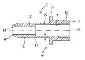
- FIG. 1is a cross-sectional view of one embodiment of an end coupling
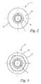
- FIG. 2is a leading end view of the end coupling of FIG. 1 ;
- FIG. 3is a trailing end view of the end coupling of FIG. 1 ;
- FIG. 4is a cross-sectional view of the end coupling of FIG. 1 in use
- FIG. 5is a cross-sectional view of the end coupling of FIG. 1 in use
- FIG. 6is a cross-sectional view of the end coupling of FIG. 1 in use
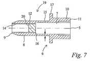
- FIG. 7is a cross-sectional view of a second embodiment of an end coupling
- FIG. 8is a cross-sectional view of the end coupling of FIG. 5 in use
- FIG. 9is a cross-sectional view of the end coupling of FIG. 5 in use.
- FIG. 10is a cross-sectional view of the end coupling of FIG. 5 in use.
- an end coupling 1 for a shaft 2 of a rock boltThe shaft 2 has an end portion 3 which has an external thread 4 .
- the coupling 1is arranged to be coupled to the external thread 4 and is adapted to allow rotation to be imparted to the shaft 2 when it is located in a bore 10 formed in rock 100 with little or no shaft tail protruding from the rock face 102 .
- the end coupling 1has an axis 5 extending longitudinally along the end coupling 1 .
- the end coupling 1is adapted to be rotated about the axis 5 .
- the end coupling 1comprises a body 6 having a lead portion 8 with a leading end 9 .
- the body 6further comprises a tail portion 10 which includes a trailing end 11 .
- the tail portion 10is arranged to be engaged with a drive to impart rotation to the coupling 1 about the axis 5 .
- the tail portion 10has a non-circular outer surface (which in the form shown is hexagonal—see FIG. 3 ).
- the body 6defines a passage 7 extending along the axis 5 between the leading end 9 and the trailing end 11 .
- the passage 7has a first portion 12 extending from and positioned proximal to the leading end 9 .
- the first portion 12 of the passage 7has an internal diameter and at least a portion of the first portion 12 of the passage 7 is internally threaded with first thread 14 .
- This first thread 14allows the first portion 12 of the passage 7 to threadedly engage the external thread 4 on the end portion 3 of the shaft 2 . Hence, this allows the shaft 2 to be threadedly engaged with the end coupling 1 .
- the body 6further includes a second portion 15 of the passage 7 which has an internal diameter greater than the internal diameter of the first portion 12 .
- the difference in diameter between the first portion 12 and the second portion 15 of the passage 7results in an abutment shoulder 16 positioned between the first portion 12 and a second portion 15 and facing the trailing end 11 .
- the end coupling 1further includes an external abutment shoulder 17 disposed on the exterior of the tail portion 10 .
- This external abutment 17is typically in the form of a flat washer or a domed washer.
- end coupling 1allows end portion 3 of the shaft 2 to be threadingly engaged with the lead portion 9 of the end coupling 1 while the tail portion 10 of the coupling 1 extends beyond the end of the shaft 2 .
- the tail portion 10is accessible for engagement with a drive which may be mounted on the tail portion 10 to rotate the shaft 2 .
- Thisallows for the shaft 2 to be positioned within a bore having little to no tail protruding from the rock face but still allows the coupling to input torque to the shaft 2 and tensioning of the rock bolt as will be described in more detail below.
- a rock bolt assemblycomprising the coupling 1 assembled on the shaft 2 .
- the shaft 2includes a stop 13 at its distal end which is arranged to locate in the second portion 15 of the passage 7 .
- the stop 13prevents the end coupling from winding off the shaft end as it is arranged to engage with the internal abutment 16 .
- the coupling 1is mounted to the shaft 2 prior to installation in the bore 101 .
- the shaftis fed into the coupling 1 from the trailing end 11 until the thread 4 on the end portion 3 moves into engagement with the first thread 14 formed on the coupling.
- the couplingis then wound in a first direction up the shaft by engagement of the threads 4 and 14 until the stop 13 moves into engagement with the abutment 16 .
- the assemblyis now in its installation position (as shown in FIG. 4 ) where any further rotation of the coupling 1 in the first direction imparts a corresponding rotation to the shaft 2 by virtue of the engagement of the stop 13 with the abutment 16 .
- the coupling 1 and shaft 2are ready to be installed in the bore 101 as shown in FIG. 4 .
- the coupling 1is able to be rotated in the first direction (typically by engaging the tail portion 10 ) which imparts a corresponding rotation to the shaft which can be used to activate a point anchor of the rock bolt (not shown) which may be either a mechanical anchor and/or a resin cartridge.
- a point anchor of the rock bolt(not shown) which may be either a mechanical anchor and/or a resin cartridge.
- the rock bolt 50is ready to be tensioned.
- Thisis achieved by rotating the coupling 1 in an opposite second direction which causes the coupling to wind down the end portion of the shaft as a result of engagement between the thread 4 on the shaft and the internal first thread 14 in the coupling.
- thiscauses the stop 13 to move out of engagement with the abutment surface and causes the external abutment 17 to move into engagement with the rock face 102 thereby placing the shaft 2 in tension.
- Rock supportis therefore achieved.
- the couplingcan be used to locate attachments 21 as shown in FIG. 6 .
- the tail portion 10 of the coupling 1includes an internal thread 18 which extends to the trailing end 11 .
- a corresponding nut 22 having an external thread 23may be secured to the tail end 11 of the coupling 1 by engagement of the threads 18 and 23 .
- FIGS. 7 to 10illustrate coupling 19 according to a second embodiment.
- the coupling 19includes many of the features of the earlier embodiment like features have been given like reference numerals.
- the primary distinction between the coupling 19 and the coupling 1 of the earlier embodimentis that a polymeric plug is positioned within the passage, specifically within the first portion 12 .
- This polymeric plugis injection moulded into the passage 7 in intimate contact with the first thread 14 of the first portion 12 .
- the coupling 19is arranged to be used with a rock bolt 50 having an end portion 3 incorporating an external thread which extends to the distal end of the shaft 2 .
- the shaft 2does not include the stop 13 as in the earlier embodiment.
- the coupling 19is arranged to be screwed on to the end portion 3 of the shaft until the end of the shaft is in abutment with the plug 20 . This arrangement is shown in FIG. 8 .
- the coupling 19is able to impart torque to the shaft 2 when the shaft is rotated in the second direction (i.e. in a direction which causes the coupling to wind down the shaft end). This torque is able to be imparted by virtue of the engagement of the end of the shaft 2 with the polymeric plug 20 .
- the polymeric plug 20When a threshold level of torque is placed on the end coupling 19 the polymeric plug 20 is arranged to disengage from the first thread 14 . At this point the polymeric plug 20 is expelled from the first portion of the passage through the tailing end 11 . typically the torque threshold at which the plug will fail is in the range of 40-160 N.m. Thereafter the coupling 19 is able to wind down the shaft end so as to cause tensioning of the shaft 2 by moving the external abutment surface 17 into engagement with the rock face 102 as shown in FIG. 9 .
- attachments 21are able to be secured to the end of the coupling by virtue of the internal thread 18 formed within the tail portion 10 of the coupling 19 .
- an end coupling and rock bolt assemblywhich allows for both the transfer of torque and tensioning of rock bolts for use in mining and similar applications.
- the couplingis multifunctional and also provides an arrangement to allow easier fitting of related attachments for use in such operations.
Landscapes
- Engineering & Computer Science (AREA)
- Mining & Mineral Resources (AREA)
- Structural Engineering (AREA)
- Life Sciences & Earth Sciences (AREA)
- General Life Sciences & Earth Sciences (AREA)
- Geochemistry & Mineralogy (AREA)
- Geology (AREA)
- Mutual Connection Of Rods And Tubes (AREA)
- Connection Of Plates (AREA)
Abstract
Description
Claims (15)
Priority Applications (1)
| Application Number | Priority Date | Filing Date | Title |
|---|---|---|---|
| US13/031,412US8172485B2 (en) | 2007-09-04 | 2011-02-21 | End coupling for a rock bolt |
Applications Claiming Priority (2)
| Application Number | Priority Date | Filing Date | Title |
|---|---|---|---|
| AU2007904781 | 2007-09-04 | ||
| AU2007904781AAU2007904781A0 (en) | 2007-09-04 | End coupling for a rock bolt |
Related Child Applications (1)
| Application Number | Title | Priority Date | Filing Date |
|---|---|---|---|
| US13/031,412ContinuationUS8172485B2 (en) | 2007-09-04 | 2011-02-21 | End coupling for a rock bolt |
Publications (2)
| Publication Number | Publication Date |
|---|---|
| US20090074517A1 US20090074517A1 (en) | 2009-03-19 |
| US7896579B2true US7896579B2 (en) | 2011-03-01 |
Family
ID=40410027
Family Applications (2)
| Application Number | Title | Priority Date | Filing Date |
|---|---|---|---|
| US12/203,365ActiveUS7896579B2 (en) | 2007-09-04 | 2008-09-03 | End coupling for a rock bolt |
| US13/031,412ActiveUS8172485B2 (en) | 2007-09-04 | 2011-02-21 | End coupling for a rock bolt |
Family Applications After (1)
| Application Number | Title | Priority Date | Filing Date |
|---|---|---|---|
| US13/031,412ActiveUS8172485B2 (en) | 2007-09-04 | 2011-02-21 | End coupling for a rock bolt |
Country Status (5)
| Country | Link |
|---|---|
| US (2) | US7896579B2 (en) |
| CN (1) | CN101392530B (en) |
| AU (1) | AU2008207662B2 (en) |
| CA (1) | CA2639268A1 (en) |
| ZA (1) | ZA200807536B (en) |
Cited By (4)
| Publication number | Priority date | Publication date | Assignee | Title |
|---|---|---|---|---|
| US20110142548A1 (en)* | 2007-09-04 | 2011-06-16 | Fci Holdings Delaware, Inc. | End Coupling for a Rock Bolt |
| US20120114425A1 (en)* | 2010-11-09 | 2012-05-10 | Hubbell Incorporated | Transition coupling between cylindrical drive shaft and helical pile shaft |
| WO2021089353A1 (en)* | 2019-11-08 | 2021-05-14 | Sandvik Mining And Construction Tools Ab | Visual indicator for correct torsion of a rock bolt |
| US11414867B2 (en)* | 2020-11-20 | 2022-08-16 | Su-I Lim | Rebar anchoring system and method |
Families Citing this family (16)
| Publication number | Priority date | Publication date | Assignee | Title |
|---|---|---|---|---|
| DE202007011491U1 (en)* | 2007-08-16 | 2007-10-18 | Acument Gmbh & Co. Ohg | Device for fastening plastic parts to a motor vehicle body |
| JP5241027B2 (en)* | 2009-06-30 | 2013-07-17 | 岡部株式会社 | Grout filling bracket |
| CN101858225B (en)* | 2010-06-10 | 2011-10-12 | 北京中矿深远能源环境科学研究院 | constant-resistance large-deformation anchor rod |
| CN102371668B (en)* | 2010-08-18 | 2014-03-12 | 邵钦蓉 | Fiber reinforced plastic bolt forming mold head, forming device and corresponding bolt preparation method |
| CN102373934A (en)* | 2010-08-18 | 2012-03-14 | 张一平 | Glass steel anchor rod, production method thereof and anchor rod component |
| DE102010043765B4 (en)* | 2010-11-11 | 2014-08-28 | Hilti Aktiengesellschaft | Armature assembly and method of making an armature assembly |
| US20150308269A1 (en)* | 2013-05-16 | 2015-10-29 | MatLok, Inc. | Mine roof bolt system |
| EP3212889A4 (en)* | 2014-10-28 | 2018-06-06 | DSI Underground IP Holdings Luxembourg S.à.r.l. | End coupling for a rock bolt |
| AU2016228128B2 (en)* | 2015-03-05 | 2021-07-29 | FCI Holdings Delaware, LLC | Fitting for a rock bolt and rock bolt assemblies including same |
| CN106401626B (en)* | 2016-06-02 | 2018-04-20 | 长春天地聚氨酯科技有限公司 | Anchor cable or anchor rod tray with polyurethane coating layer and manufacturing method thereof |
| CN106402054A (en)* | 2016-12-07 | 2017-02-15 | 耒阳市金鑫农业科技发展有限公司 | Hydraulic pressure change joint for oil press |
| EP3673151B1 (en)* | 2017-08-22 | 2023-06-07 | Sandvik Intellectual Property AB | Rock bolt with meshing adapter |
| ES2972644T3 (en)* | 2017-11-27 | 2024-06-13 | Sandvik Intellectual Property | Rock Bolt with Hitch Adapter |
| PT3536894T (en)* | 2018-03-09 | 2020-11-19 | Sandvik Mining And Construction Tools Ab | Coupling for connecting downhole tubulars |
| EP3613943B1 (en)* | 2018-08-23 | 2023-06-07 | Sandvik Mining and Construction Australia (Production/Supply) Pty Ltd | Rock bolt with information display region |
| CN112868318A (en)* | 2021-01-11 | 2021-06-01 | 上海岛茵智能科技有限公司 | Agricultural robot seeder technology |
Citations (11)
| Publication number | Priority date | Publication date | Assignee | Title |
|---|---|---|---|---|
| US4295761A (en)* | 1979-12-10 | 1981-10-20 | Stratabolt Corporation | Post tensionable grouted anchor assembly |
| US4303354A (en)* | 1979-03-28 | 1981-12-01 | Peabody Coal Company | Mine roof bolting |
| US4349299A (en)* | 1980-02-26 | 1982-09-14 | Stephen F. Koval | Roof bolt tension head and method of use |
| US4427326A (en)* | 1982-05-11 | 1984-01-24 | Image Industries, Inc. | Tamper-resistant lug nut |
| US4502825A (en)* | 1981-03-30 | 1985-03-05 | Kyodo Electric Co., Ltd. | Multi-headed screw |
| US4618291A (en)* | 1985-02-22 | 1986-10-21 | The Eastern Company | Nut member and mine roof support system incorporating same |
| US4957401A (en)* | 1982-01-11 | 1990-09-18 | Hi-Shear Corporation | Threaded fastener having minimized length and weight and method to make it |
| US5791823A (en)* | 1996-12-06 | 1998-08-11 | Inco Limited | Yielding head for mine support |
| US5865581A (en)* | 1997-04-16 | 1999-02-02 | Huck International, Inc. | Free running prevailing torque nut |
| US6994496B2 (en)* | 2002-05-10 | 2006-02-07 | Minova International Limited | Roof bolts for use in mines, a method for their production and a method for their installation |
| US7001109B2 (en)* | 2003-12-03 | 2006-02-21 | Rock Mongrain | Apparatus for ground support |
Family Cites Families (3)
| Publication number | Priority date | Publication date | Assignee | Title |
|---|---|---|---|---|
| CN2903182Y (en)* | 2006-05-29 | 2007-05-23 | 上海禧龙建筑科技发展有限公司 | Self drilling type prestressing anchor |
| CN100453743C (en)* | 2006-06-05 | 2009-01-21 | 吴德兴 | Prestress anchor device |
| AU2008207662B2 (en)* | 2007-09-04 | 2015-02-05 | Fci Holdings Delaware, Inc. | End coupling for a rock bolt |
- 2008
- 2008-09-01AUAU2008207662Apatent/AU2008207662B2/ennot_activeCeased
- 2008-09-02ZAZA200807536Apatent/ZA200807536B/enunknown
- 2008-09-03USUS12/203,365patent/US7896579B2/enactiveActive
- 2008-09-03CACA002639268Apatent/CA2639268A1/ennot_activeAbandoned
- 2008-09-04CNCN2008101769468Apatent/CN101392530B/ennot_activeExpired - Fee Related
- 2011
- 2011-02-21USUS13/031,412patent/US8172485B2/enactiveActive
Patent Citations (11)
| Publication number | Priority date | Publication date | Assignee | Title |
|---|---|---|---|---|
| US4303354A (en)* | 1979-03-28 | 1981-12-01 | Peabody Coal Company | Mine roof bolting |
| US4295761A (en)* | 1979-12-10 | 1981-10-20 | Stratabolt Corporation | Post tensionable grouted anchor assembly |
| US4349299A (en)* | 1980-02-26 | 1982-09-14 | Stephen F. Koval | Roof bolt tension head and method of use |
| US4502825A (en)* | 1981-03-30 | 1985-03-05 | Kyodo Electric Co., Ltd. | Multi-headed screw |
| US4957401A (en)* | 1982-01-11 | 1990-09-18 | Hi-Shear Corporation | Threaded fastener having minimized length and weight and method to make it |
| US4427326A (en)* | 1982-05-11 | 1984-01-24 | Image Industries, Inc. | Tamper-resistant lug nut |
| US4618291A (en)* | 1985-02-22 | 1986-10-21 | The Eastern Company | Nut member and mine roof support system incorporating same |
| US5791823A (en)* | 1996-12-06 | 1998-08-11 | Inco Limited | Yielding head for mine support |
| US5865581A (en)* | 1997-04-16 | 1999-02-02 | Huck International, Inc. | Free running prevailing torque nut |
| US6994496B2 (en)* | 2002-05-10 | 2006-02-07 | Minova International Limited | Roof bolts for use in mines, a method for their production and a method for their installation |
| US7001109B2 (en)* | 2003-12-03 | 2006-02-21 | Rock Mongrain | Apparatus for ground support |
Cited By (8)
| Publication number | Priority date | Publication date | Assignee | Title |
|---|---|---|---|---|
| US20110142548A1 (en)* | 2007-09-04 | 2011-06-16 | Fci Holdings Delaware, Inc. | End Coupling for a Rock Bolt |
| US8172485B2 (en)* | 2007-09-04 | 2012-05-08 | Fci Holdings Delaware, Inc. | End coupling for a rock bolt |
| US20120114425A1 (en)* | 2010-11-09 | 2012-05-10 | Hubbell Incorporated | Transition coupling between cylindrical drive shaft and helical pile shaft |
| US8888413B2 (en)* | 2010-11-09 | 2014-11-18 | Hubbell Incorporated | Transition coupling between cylindrical drive shaft and helical pile shaft |
| WO2021089353A1 (en)* | 2019-11-08 | 2021-05-14 | Sandvik Mining And Construction Tools Ab | Visual indicator for correct torsion of a rock bolt |
| US12203372B2 (en) | 2019-11-08 | 2025-01-21 | Sandvik Mining And Construction Tools Ab | Visual indicator for correct torsion of a rock bolt |
| AU2020380573B2 (en)* | 2019-11-08 | 2025-09-25 | Sandvik Mining And Construction Australia Pty Ltd | Visual indicator for correct torsion of a rock bolt |
| US11414867B2 (en)* | 2020-11-20 | 2022-08-16 | Su-I Lim | Rebar anchoring system and method |
Also Published As
| Publication number | Publication date |
|---|---|
| US20110142548A1 (en) | 2011-06-16 |
| ZA200807536B (en) | 2009-04-29 |
| CN101392530A (en) | 2009-03-25 |
| US8172485B2 (en) | 2012-05-08 |
| AU2008207662A1 (en) | 2009-03-19 |
| CN101392530B (en) | 2011-04-06 |
| US20090074517A1 (en) | 2009-03-19 |
| CA2639268A1 (en) | 2009-03-04 |
| AU2008207662B2 (en) | 2015-02-05 |
Similar Documents
| Publication | Publication Date | Title |
|---|---|---|
| US7896579B2 (en) | End coupling for a rock bolt | |
| US10309221B2 (en) | End coupling for a rock bolt | |
| US11131190B2 (en) | Friction rock bolt | |
| US10066483B2 (en) | Friction bolt assembly | |
| US8926230B2 (en) | Tension cable bolt | |
| US4655645A (en) | Method and apparatus for anchoring roof bolts | |
| AU2017219084A1 (en) | Improved torque tensioning system for cable bolts | |
| ZA200801036B (en) | Tensioning assembly for a cable bolt | |
| US5052861A (en) | Roof bolt with plastic sleeve and mechanical anchor | |
| US20100310323A1 (en) | Rock bolt assembly | |
| AU2016228128A1 (en) | Fitting for a rock bolt and rock bolt assemblies including same | |
| AU2015345983B2 (en) | Drive assembly | |
| ZA200902680B (en) | Tension assembly | |
| AU2011101711A4 (en) | Rock Bolt | |
| AU2015202429A1 (en) | A rock bolt installation and method of installing a rock bolt | |
| AU2013100231A4 (en) | Tension indicator | |
| AU2014203600A1 (en) | Rock bolt assembly | |
| AU2015101246B4 (en) | Rock bolt fitting and assembly including same | |
| AU2016202889A1 (en) | Friction bolt assembly | |
| AU2014101221A4 (en) | Tension assembly |
Legal Events
| Date | Code | Title | Description |
|---|---|---|---|
| AS | Assignment | Owner name:JENNMAR CORPORATION, PENNSYLVANIA Free format text:ASSIGNMENT OF ASSIGNORS INTEREST;ASSIGNOR:CRAIG, PETER HAROLD, MR.;REEL/FRAME:021873/0579 Effective date:20081028 | |
| AS | Assignment | Owner name:JENNMAR OF PENNSYLVANIA, LLC,PENNSYLVANIA Free format text:MERGER;ASSIGNOR:JENNMAR CORPORATION;REEL/FRAME:024103/0575 Effective date:20091221 Owner name:FCI HOLDINGS DELAWARE, INC.,PENNSYLVANIA Free format text:PATENT ASSIGNMENT CONFIRMATION;ASSIGNOR:JENNMAR OF PENNSYLVANIA, LLC;REEL/FRAME:024103/0622 Effective date:20100317 Owner name:JENNMAR OF PENNSYLVANIA, LLC, PENNSYLVANIA Free format text:MERGER;ASSIGNOR:JENNMAR CORPORATION;REEL/FRAME:024103/0575 Effective date:20091221 Owner name:FCI HOLDINGS DELAWARE, INC., PENNSYLVANIA Free format text:PATENT ASSIGNMENT CONFIRMATION;ASSIGNOR:JENNMAR OF PENNSYLVANIA, LLC;REEL/FRAME:024103/0622 Effective date:20100317 | |
| STCF | Information on status: patent grant | Free format text:PATENTED CASE | |
| AS | Assignment | Owner name:PNC BANK, NATIONAL ASSOCIATION, AS AGENT, PENNSYLV Free format text:SECURITY AGREEMENT;ASSIGNOR:FCI HOLDINGS DELAWARE, INC.;REEL/FRAME:026205/0001 Effective date:20110427 | |
| FPAY | Fee payment | Year of fee payment:4 | |
| SULP | Surcharge for late payment | ||
| AS | Assignment | Owner name:FCI HOLDINGS DELAWARE, INC., PENNSYLVANIA Free format text:RELEASE OF SECURITY INTEREST IN INTELLECTUAL PROPERTY;ASSIGNOR:PNC BANK, NATIONAL ASSOCIATION;REEL/FRAME:037963/0923 Effective date:20160229 | |
| AS | Assignment | Owner name:WELLS FARGO BANK, NATIONAL ASSOCIATION, NEW YORK Free format text:SECURITY AGREEMENT;ASSIGNORS:DSI UNDERGROUND SYSTEMS, LLC;FCI HOLDINGS DELAWARE, INC., A DELAWARE CORPORATION;J-LOK CO., A PENNSYLVANIA CORPORATION;REEL/FRAME:038179/0591 Effective date:20160229 | |
| FEPP | Fee payment procedure | Free format text:7.5 YR SURCHARGE - LATE PMT W/IN 6 MO, LARGE ENTITY (ORIGINAL EVENT CODE: M1555); ENTITY STATUS OF PATENT OWNER: LARGE ENTITY | |
| MAFP | Maintenance fee payment | Free format text:PAYMENT OF MAINTENANCE FEE, 8TH YEAR, LARGE ENTITY (ORIGINAL EVENT CODE: M1552); ENTITY STATUS OF PATENT OWNER: LARGE ENTITY Year of fee payment:8 | |
| FEPP | Fee payment procedure | Free format text:11.5 YR SURCHARGE- LATE PMT W/IN 6 MO, LARGE ENTITY (ORIGINAL EVENT CODE: M1556); ENTITY STATUS OF PATENT OWNER: LARGE ENTITY | |
| MAFP | Maintenance fee payment | Free format text:PAYMENT OF MAINTENANCE FEE, 12TH YEAR, LARGE ENTITY (ORIGINAL EVENT CODE: M1553); ENTITY STATUS OF PATENT OWNER: LARGE ENTITY Year of fee payment:12 | |
| AS | Assignment | Owner name:FCI HOLDINGS DELAWARE, LLC, DELAWARE Free format text:CHANGE OF NAME;ASSIGNOR:FCI HOLDINGS DELAWARE, INC.;REEL/FRAME:071297/0130 Effective date:20240229 |