US7895927B2 - Power equipment with detection and reaction systems - Google Patents
Power equipment with detection and reaction systemsDownload PDFInfo
- Publication number
- US7895927B2 US7895927B2US12/800,607US80060710AUS7895927B2US 7895927 B2US7895927 B2US 7895927B2US 80060710 AUS80060710 AUS 80060710AUS 7895927 B2US7895927 B2US 7895927B2
- Authority
- US
- United States
- Prior art keywords
- blade
- ser
- filed
- cutting tool
- provisional patent
- Prior art date
- Legal status (The legal status is an assumption and is not a legal conclusion. Google has not performed a legal analysis and makes no representation as to the accuracy of the status listed.)
- Expired - Fee Related
Links
Images


Classifications
- B—PERFORMING OPERATIONS; TRANSPORTING
- B26—HAND CUTTING TOOLS; CUTTING; SEVERING
- B26D—CUTTING; DETAILS COMMON TO MACHINES FOR PERFORATING, PUNCHING, CUTTING-OUT, STAMPING-OUT OR SEVERING
- B26D7/00—Details of apparatus for cutting, cutting-out, stamping-out, punching, perforating, or severing by means other than cutting
- B26D7/22—Safety devices specially adapted for cutting machines
- B26D7/24—Safety devices specially adapted for cutting machines arranged to disable the operating means for the cutting member
- B—PERFORMING OPERATIONS; TRANSPORTING
- B23—MACHINE TOOLS; METAL-WORKING NOT OTHERWISE PROVIDED FOR
- B23D—PLANING; SLOTTING; SHEARING; BROACHING; SAWING; FILING; SCRAPING; LIKE OPERATIONS FOR WORKING METAL BY REMOVING MATERIAL, NOT OTHERWISE PROVIDED FOR
- B23D47/00—Sawing machines or sawing devices working with circular saw blades, characterised only by constructional features of particular parts
- B23D47/02—Sawing machines or sawing devices working with circular saw blades, characterised only by constructional features of particular parts of frames; of guiding arrangements for work-table or saw-carrier
- B23D47/025—Sawing machines or sawing devices working with circular saw blades, characterised only by constructional features of particular parts of frames; of guiding arrangements for work-table or saw-carrier of tables
- B—PERFORMING OPERATIONS; TRANSPORTING
- B23—MACHINE TOOLS; METAL-WORKING NOT OTHERWISE PROVIDED FOR
- B23D—PLANING; SLOTTING; SHEARING; BROACHING; SAWING; FILING; SCRAPING; LIKE OPERATIONS FOR WORKING METAL BY REMOVING MATERIAL, NOT OTHERWISE PROVIDED FOR
- B23D47/00—Sawing machines or sawing devices working with circular saw blades, characterised only by constructional features of particular parts
- B23D47/08—Sawing machines or sawing devices working with circular saw blades, characterised only by constructional features of particular parts of devices for bringing the circular saw blade to the workpiece or removing same therefrom
- B—PERFORMING OPERATIONS; TRANSPORTING
- B23—MACHINE TOOLS; METAL-WORKING NOT OTHERWISE PROVIDED FOR
- B23D—PLANING; SLOTTING; SHEARING; BROACHING; SAWING; FILING; SCRAPING; LIKE OPERATIONS FOR WORKING METAL BY REMOVING MATERIAL, NOT OTHERWISE PROVIDED FOR
- B23D59/00—Accessories specially designed for sawing machines or sawing devices
- B23D59/001—Measuring or control devices, e.g. for automatic control of work feed pressure on band saw blade
- B—PERFORMING OPERATIONS; TRANSPORTING
- B27—WORKING OR PRESERVING WOOD OR SIMILAR MATERIAL; NAILING OR STAPLING MACHINES IN GENERAL
- B27B—SAWS FOR WOOD OR SIMILAR MATERIAL; COMPONENTS OR ACCESSORIES THEREFOR
- B27B13/00—Band or strap sawing machines; Components or equipment therefor
- B27B13/14—Braking devices specially designed for band sawing machines, e.g. acting after damage of the band saw blade
- B—PERFORMING OPERATIONS; TRANSPORTING
- B27—WORKING OR PRESERVING WOOD OR SIMILAR MATERIAL; NAILING OR STAPLING MACHINES IN GENERAL
- B27B—SAWS FOR WOOD OR SIMILAR MATERIAL; COMPONENTS OR ACCESSORIES THEREFOR
- B27B5/00—Sawing machines working with circular or cylindrical saw blades; Components or equipment therefor
- B27B5/29—Details; Component parts; Accessories
- B27B5/38—Devices for braking the circular saw blade or the saw spindle; Devices for damping vibrations of the circular saw blade, e.g. silencing
- B—PERFORMING OPERATIONS; TRANSPORTING
- B27—WORKING OR PRESERVING WOOD OR SIMILAR MATERIAL; NAILING OR STAPLING MACHINES IN GENERAL
- B27G—ACCESSORY MACHINES OR APPARATUS FOR WORKING WOOD OR SIMILAR MATERIALS; TOOLS FOR WORKING WOOD OR SIMILAR MATERIALS; SAFETY DEVICES FOR WOOD WORKING MACHINES OR TOOLS
- B27G19/00—Safety guards or devices specially adapted for wood saws; Auxiliary devices facilitating proper operation of wood saws
- B27G19/02—Safety guards or devices specially adapted for wood saws; Auxiliary devices facilitating proper operation of wood saws for circular saws
- B—PERFORMING OPERATIONS; TRANSPORTING
- B27—WORKING OR PRESERVING WOOD OR SIMILAR MATERIAL; NAILING OR STAPLING MACHINES IN GENERAL
- B27G—ACCESSORY MACHINES OR APPARATUS FOR WORKING WOOD OR SIMILAR MATERIALS; TOOLS FOR WORKING WOOD OR SIMILAR MATERIALS; SAFETY DEVICES FOR WOOD WORKING MACHINES OR TOOLS
- B27G19/00—Safety guards or devices specially adapted for wood saws; Auxiliary devices facilitating proper operation of wood saws
- B27G19/06—Safety guards or devices specially adapted for wood saws; Auxiliary devices facilitating proper operation of wood saws for band or strap saws
- F—MECHANICAL ENGINEERING; LIGHTING; HEATING; WEAPONS; BLASTING
- F16—ENGINEERING ELEMENTS AND UNITS; GENERAL MEASURES FOR PRODUCING AND MAINTAINING EFFECTIVE FUNCTIONING OF MACHINES OR INSTALLATIONS; THERMAL INSULATION IN GENERAL
- F16P—SAFETY DEVICES IN GENERAL; SAFETY DEVICES FOR PRESSES
- F16P3/00—Safety devices acting in conjunction with the control or operation of a machine; Control arrangements requiring the simultaneous use of two or more parts of the body
- F16P3/12—Safety devices acting in conjunction with the control or operation of a machine; Control arrangements requiring the simultaneous use of two or more parts of the body with means, e.g. feelers, which in case of the presence of a body part of a person in or near the danger zone influence the control or operation of the machine
- F16P3/14—Safety devices acting in conjunction with the control or operation of a machine; Control arrangements requiring the simultaneous use of two or more parts of the body with means, e.g. feelers, which in case of the presence of a body part of a person in or near the danger zone influence the control or operation of the machine the means being photocells or other devices sensitive without mechanical contact
- F16P3/148—Safety devices acting in conjunction with the control or operation of a machine; Control arrangements requiring the simultaneous use of two or more parts of the body with means, e.g. feelers, which in case of the presence of a body part of a person in or near the danger zone influence the control or operation of the machine the means being photocells or other devices sensitive without mechanical contact using capacitive technology
- G—PHYSICS
- G05—CONTROLLING; REGULATING
- G05B—CONTROL OR REGULATING SYSTEMS IN GENERAL; FUNCTIONAL ELEMENTS OF SUCH SYSTEMS; MONITORING OR TESTING ARRANGEMENTS FOR SUCH SYSTEMS OR ELEMENTS
- G05B9/00—Safety arrangements
- G05B9/02—Safety arrangements electric
- Y—GENERAL TAGGING OF NEW TECHNOLOGICAL DEVELOPMENTS; GENERAL TAGGING OF CROSS-SECTIONAL TECHNOLOGIES SPANNING OVER SEVERAL SECTIONS OF THE IPC; TECHNICAL SUBJECTS COVERED BY FORMER USPC CROSS-REFERENCE ART COLLECTIONS [XRACs] AND DIGESTS
- Y10—TECHNICAL SUBJECTS COVERED BY FORMER USPC
- Y10S—TECHNICAL SUBJECTS COVERED BY FORMER USPC CROSS-REFERENCE ART COLLECTIONS [XRACs] AND DIGESTS
- Y10S83/00—Cutting
- Y10S83/01—Safety devices
- Y—GENERAL TAGGING OF NEW TECHNOLOGICAL DEVELOPMENTS; GENERAL TAGGING OF CROSS-SECTIONAL TECHNOLOGIES SPANNING OVER SEVERAL SECTIONS OF THE IPC; TECHNICAL SUBJECTS COVERED BY FORMER USPC CROSS-REFERENCE ART COLLECTIONS [XRACs] AND DIGESTS
- Y10—TECHNICAL SUBJECTS COVERED BY FORMER USPC
- Y10T—TECHNICAL SUBJECTS COVERED BY FORMER US CLASSIFICATION
- Y10T83/00—Cutting
- Y10T83/04—Processes
- Y—GENERAL TAGGING OF NEW TECHNOLOGICAL DEVELOPMENTS; GENERAL TAGGING OF CROSS-SECTIONAL TECHNOLOGIES SPANNING OVER SEVERAL SECTIONS OF THE IPC; TECHNICAL SUBJECTS COVERED BY FORMER USPC CROSS-REFERENCE ART COLLECTIONS [XRACs] AND DIGESTS
- Y10—TECHNICAL SUBJECTS COVERED BY FORMER USPC
- Y10T—TECHNICAL SUBJECTS COVERED BY FORMER US CLASSIFICATION
- Y10T83/00—Cutting
- Y10T83/081—With randomly actuated stopping means
- Y10T83/088—Responsive to tool detector or work-feed-means detector
- Y10T83/089—Responsive to tool characteristic
- Y—GENERAL TAGGING OF NEW TECHNOLOGICAL DEVELOPMENTS; GENERAL TAGGING OF CROSS-SECTIONAL TECHNOLOGIES SPANNING OVER SEVERAL SECTIONS OF THE IPC; TECHNICAL SUBJECTS COVERED BY FORMER USPC CROSS-REFERENCE ART COLLECTIONS [XRACs] AND DIGESTS
- Y10—TECHNICAL SUBJECTS COVERED BY FORMER USPC
- Y10T—TECHNICAL SUBJECTS COVERED BY FORMER US CLASSIFICATION
- Y10T83/00—Cutting
- Y10T83/081—With randomly actuated stopping means
- Y10T83/091—Responsive to work sensing means
- Y—GENERAL TAGGING OF NEW TECHNOLOGICAL DEVELOPMENTS; GENERAL TAGGING OF CROSS-SECTIONAL TECHNOLOGIES SPANNING OVER SEVERAL SECTIONS OF THE IPC; TECHNICAL SUBJECTS COVERED BY FORMER USPC CROSS-REFERENCE ART COLLECTIONS [XRACs] AND DIGESTS
- Y10—TECHNICAL SUBJECTS COVERED BY FORMER USPC
- Y10T—TECHNICAL SUBJECTS COVERED BY FORMER US CLASSIFICATION
- Y10T83/00—Cutting
- Y10T83/141—With means to monitor and control operation [e.g., self-regulating means]
- Y—GENERAL TAGGING OF NEW TECHNOLOGICAL DEVELOPMENTS; GENERAL TAGGING OF CROSS-SECTIONAL TECHNOLOGIES SPANNING OVER SEVERAL SECTIONS OF THE IPC; TECHNICAL SUBJECTS COVERED BY FORMER USPC CROSS-REFERENCE ART COLLECTIONS [XRACs] AND DIGESTS
- Y10—TECHNICAL SUBJECTS COVERED BY FORMER USPC
- Y10T—TECHNICAL SUBJECTS COVERED BY FORMER US CLASSIFICATION
- Y10T83/00—Cutting
- Y10T83/162—With control means responsive to replaceable or selectable information program
- Y10T83/173—Arithmetically determined program
- Y10T83/175—With condition sensor
- Y10T83/178—Responsive to work
- Y—GENERAL TAGGING OF NEW TECHNOLOGICAL DEVELOPMENTS; GENERAL TAGGING OF CROSS-SECTIONAL TECHNOLOGIES SPANNING OVER SEVERAL SECTIONS OF THE IPC; TECHNICAL SUBJECTS COVERED BY FORMER USPC CROSS-REFERENCE ART COLLECTIONS [XRACs] AND DIGESTS
- Y10—TECHNICAL SUBJECTS COVERED BY FORMER USPC
- Y10T—TECHNICAL SUBJECTS COVERED BY FORMER US CLASSIFICATION
- Y10T83/00—Cutting
- Y10T83/525—Operation controlled by detector means responsive to work
- Y10T83/541—Actuation of tool controlled in response to work-sensing means
- Y—GENERAL TAGGING OF NEW TECHNOLOGICAL DEVELOPMENTS; GENERAL TAGGING OF CROSS-SECTIONAL TECHNOLOGIES SPANNING OVER SEVERAL SECTIONS OF THE IPC; TECHNICAL SUBJECTS COVERED BY FORMER USPC CROSS-REFERENCE ART COLLECTIONS [XRACs] AND DIGESTS
- Y10—TECHNICAL SUBJECTS COVERED BY FORMER USPC
- Y10T—TECHNICAL SUBJECTS COVERED BY FORMER US CLASSIFICATION
- Y10T83/00—Cutting
- Y10T83/606—Interrelated tool actuating means and guard means
- Y10T83/613—Work guard
- Y—GENERAL TAGGING OF NEW TECHNOLOGICAL DEVELOPMENTS; GENERAL TAGGING OF CROSS-SECTIONAL TECHNOLOGIES SPANNING OVER SEVERAL SECTIONS OF THE IPC; TECHNICAL SUBJECTS COVERED BY FORMER USPC CROSS-REFERENCE ART COLLECTIONS [XRACs] AND DIGESTS
- Y10—TECHNICAL SUBJECTS COVERED BY FORMER USPC
- Y10T—TECHNICAL SUBJECTS COVERED BY FORMER US CLASSIFICATION
- Y10T83/00—Cutting
- Y10T83/768—Rotatable disc tool pair or tool and carrier
- Y10T83/7684—With means to support work relative to tool[s]
- Y10T83/7693—Tool moved relative to work-support during cutting
- Y10T83/7697—Tool angularly adjustable relative to work-support
- Y—GENERAL TAGGING OF NEW TECHNOLOGICAL DEVELOPMENTS; GENERAL TAGGING OF CROSS-SECTIONAL TECHNOLOGIES SPANNING OVER SEVERAL SECTIONS OF THE IPC; TECHNICAL SUBJECTS COVERED BY FORMER USPC CROSS-REFERENCE ART COLLECTIONS [XRACs] AND DIGESTS
- Y10—TECHNICAL SUBJECTS COVERED BY FORMER USPC
- Y10T—TECHNICAL SUBJECTS COVERED BY FORMER US CLASSIFICATION
- Y10T83/00—Cutting
- Y10T83/768—Rotatable disc tool pair or tool and carrier
- Y10T83/7684—With means to support work relative to tool[s]
- Y10T83/7722—Support and tool relatively adjustable
- Y10T83/7726—By movement of the tool
- Y—GENERAL TAGGING OF NEW TECHNOLOGICAL DEVELOPMENTS; GENERAL TAGGING OF CROSS-SECTIONAL TECHNOLOGIES SPANNING OVER SEVERAL SECTIONS OF THE IPC; TECHNICAL SUBJECTS COVERED BY FORMER USPC CROSS-REFERENCE ART COLLECTIONS [XRACs] AND DIGESTS
- Y10—TECHNICAL SUBJECTS COVERED BY FORMER USPC
- Y10T—TECHNICAL SUBJECTS COVERED BY FORMER US CLASSIFICATION
- Y10T83/00—Cutting
- Y10T83/768—Rotatable disc tool pair or tool and carrier
- Y10T83/7734—With guard for tool
- Y—GENERAL TAGGING OF NEW TECHNOLOGICAL DEVELOPMENTS; GENERAL TAGGING OF CROSS-SECTIONAL TECHNOLOGIES SPANNING OVER SEVERAL SECTIONS OF THE IPC; TECHNICAL SUBJECTS COVERED BY FORMER USPC CROSS-REFERENCE ART COLLECTIONS [XRACs] AND DIGESTS
- Y10—TECHNICAL SUBJECTS COVERED BY FORMER USPC
- Y10T—TECHNICAL SUBJECTS COVERED BY FORMER US CLASSIFICATION
- Y10T83/00—Cutting
- Y10T83/768—Rotatable disc tool pair or tool and carrier
- Y10T83/7755—Carrier for rotatable tool movable during cutting
- Y10T83/7788—Tool carrier oscillated or rotated
- Y—GENERAL TAGGING OF NEW TECHNOLOGICAL DEVELOPMENTS; GENERAL TAGGING OF CROSS-SECTIONAL TECHNOLOGIES SPANNING OVER SEVERAL SECTIONS OF THE IPC; TECHNICAL SUBJECTS COVERED BY FORMER USPC CROSS-REFERENCE ART COLLECTIONS [XRACs] AND DIGESTS
- Y10—TECHNICAL SUBJECTS COVERED BY FORMER USPC
- Y10T—TECHNICAL SUBJECTS COVERED BY FORMER US CLASSIFICATION
- Y10T83/00—Cutting
- Y10T83/849—With signal, scale, or indicator
- Y10T83/85—Signal; e.g., alarm
- Y—GENERAL TAGGING OF NEW TECHNOLOGICAL DEVELOPMENTS; GENERAL TAGGING OF CROSS-SECTIONAL TECHNOLOGIES SPANNING OVER SEVERAL SECTIONS OF THE IPC; TECHNICAL SUBJECTS COVERED BY FORMER USPC CROSS-REFERENCE ART COLLECTIONS [XRACs] AND DIGESTS
- Y10—TECHNICAL SUBJECTS COVERED BY FORMER USPC
- Y10T—TECHNICAL SUBJECTS COVERED BY FORMER US CLASSIFICATION
- Y10T83/00—Cutting
- Y10T83/869—Means to drive or to guide tool
- Y10T83/8773—Bevel or miter cut
Definitions
- the present disclosurerelates to safety systems and more particularly to methods for enhancing the safety of power equipment.
- Power equipmentsuch as table saws, miter saws and other woodworking machinery include cutting tools like circular saw blades and knife blades that present a risk of injury to a user of the equipment. Accordingly, safety features or systems are incorporated with power equipment to minimize the risk of injury.
- a guardthat physically blocks an operator from making contact with dangerous components of machinery, such as belts, shafts or blades. In many cases, guards effectively reduce the risk of injury, however, there are many instances where the nature of the operations to be performed precludes using a guard that completely blocks access to hazardous machine parts.
- U.S. Pat. No. 4,117,752which is herein incorporated by reference, discloses a braking system for use with a band saw, where the brake is triggered by actual contact between the user's hand and the blade.
- the system described for detecting blade contactdoes not appear to be functional to accurately and reliably detect contact.
- the systemrelies on standard electromagnetic brakes operating off of line voltage to stop the blade and pulleys of the band saw. It is believed that such brakes would take 50 ms-1 s to stop the blade. Therefore, the system is too slow to stop the blade quickly enough to avoid serious injury.
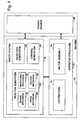
- FIG. 1is a schematic block diagram of a machine with a fast-acting safety system.
- FIG. 2is a schematic diagram of an exemplary safety system in the context of a machine having a circular blade.
- FIG. 3is a schematic side view of a table saw with a retraction system.
- FIG. 4is a schematic side view of a second side of a table saw with a retraction system.
- FIG. 5is a schematic, side view of a saw with another embodiment of a retraction system.
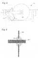
- FIG. 6is a section view of a retraction system using a deformable bushing.
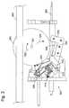
- FIG. 7is a schematic side view of a miter saw with a retraction system.
- FIG. 8is a section view of the miter saw shown in FIG. 7 .
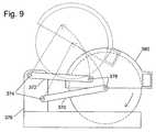
- FIG. 9shows another embodiment of a miter saw with a retraction system.
- FIG. 10shows a schematic drawing of a retraction system using a spring to retract a cutting tool.
- FIG. 11is a sectional view of the retraction system shown in FIG. 10 .
- FIG. 12also is a sectional view of the retraction system shown in FIG. 10 .
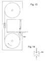
- FIG. 13is a schematic view of a band saw with a retraction system.
- FIG. 14is a top view of a roller used in the system shown in FIG. 13 .
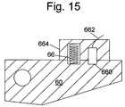
- FIG. 15shows an explosive charge that can be triggered by a firing subsystem.
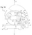
- FIG. 16is a schematic side elevation view of a miter saw having an alternative exemplary safety system configured to stop the miter saw pivot arm as well as the blade.
- FIG. 17is a magnified side view of an exemplary retraction assembly according to the present invention.
- FIG. 18is a magnified cross-sectional view of the retraction assembly of FIG. 17 .
- FIG. 19is a magnified, fragmentary view of the retraction assembly of FIG. 17 , showing the restraining mechanism in detail.
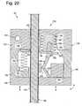
- FIG. 20is similar to FIG. 18 except that the clamping device is shown pivoted to the locked position.
- FIG. 21is similar to FIG. 20 except that the housing is shown pushed upward relative to the brace member. For clarity, the components of the restraining member are not shown.
- Machine 10may be any of a variety of different machines adapted for cutting workpieces, such as wood, including a table saw, miter saw (chop saw), radial arm saw, circular saw, band saw, jointer, planer, etc.
- Machine 10includes an operative structure 12 having a cutting tool 14 and a motor assembly 16 adapted to drive the cutting tool.
- Machine 10also includes a safety system 18 configured to minimize the potential of a serious injury to a person using machine 10 .
- Safety system 18is adapted to detect the occurrence of one or more dangerous conditions during use of machine 10 . If such a dangerous condition is detected, safety system 18 is adapted to engage operative structure 12 to limit any injury to the user caused by the dangerous condition.
- Machine 10also includes a suitable power source 20 to provide power to operative structure 12 and safety system 18 .
- Power source 20may be an external power source such as line current, or an internal power source such as a battery.
- power source 20may include a combination of both external and internal power sources.
- power source 20may include two or more separate power sources, each adapted to power different portions of machine 10 .
- operative structure 12may take any one of many different forms, depending on the type of machine 10 .
- operative structure 12may include a stationary housing configured to support motor assembly 16 in driving engagement with cutting tool 14 .
- operative structure 12may include a movable structure configured to carry cutting tool 14 between multiple operating positions.
- operative structure 12may include one or more transport mechanisms adapted to convey a workpiece toward and/or away from cutting tool 14 .
- Motor assembly 16includes one or more motors adapted to drive cutting tool 14 .
- the motorsmay be either directly or indirectly coupled to the cutting tool, and may also be adapted to drive workpiece transport mechanisms.
- Cutting tool 14typically includes one or more blades or other suitable cutting implements that are adapted to cut or remove portions from the workpieces.
- the particular form of cutting tool 14will vary depending upon the various embodiments of machine 10 .
- cutting tool 14will typically include one or more circular rotating blades having a plurality of teeth disposed along the perimetrical edge of the blade.
- the cutting tooltypically includes a plurality of radially spaced-apart blades.
- the cutting toolincludes an elongate, circuitous tooth-edged band.
- Safety system 18includes a detection subsystem 22 , a reaction subsystem 24 and a control subsystem 26 .
- Control subsystem 26may be adapted to receive inputs from a variety of sources including detection subsystem 22 , reaction subsystem 24 , operative structure 12 and motor assembly 16 .
- the control subsystemmay also include one or more sensors adapted to monitor selected parameters of machine 10 .
- control subsystem 26typically includes one or more instruments operable by a user to control the machine.
- the control subsystemis configured to control machine 10 in response to the inputs it receives.
- Detection subsystem 22is configured to detect one or more dangerous, or triggering, conditions during use of machine 10 .
- the detection subsystemmay be configured to detect that a portion of the user's body is dangerously close to, or in contact with, a portion of cutting tool 14 .
- the detection subsystemmay be configured to detect the rapid movement of a workpiece due to kickback by the cutting tool, as is described in U.S. Provisional Patent Application Ser. No. 60/182,866, the disclosure of which is herein incorporated by reference.
- detection subsystem 22may inform control subsystem 26 of the dangerous condition, which then activates reaction subsystem 24 .
- the detection subsystemmay be adapted to activate the reaction subsystem directly.
- reaction subsystem 24is configured to engage operative structure 12 quickly to prevent serious injury to the user. It will be appreciated that the particular action to be taken by reaction subsystem 24 will vary depending on the type of machine 10 and/or the dangerous condition that is detected. For example, reaction subsystem 24 may be configured to do one or more of the following: stop the movement of cutting tool 14 , disconnect motor assembly 16 from power source 20 , place a barrier between the cutting tool and the user, or retract the cutting tool from its operating position, etc. The reaction subsystem may be configured to take a combination of steps to protect the user from serious injury. Placement of a barrier between the cutting tool and teeth is described in more detail in U.S. Provisional Patent Application Ser. No. 60/225,206, entitled “Cutting Tool Safety System,” filed Aug. 14, 2000 by SD3, LLC, the disclosure of which is herein incorporated by reference.
- reaction subsystem 24typically will vary depending on which action(s) are taken.
- reaction subsystem 24is configured to stop the movement of cutting tool 14 and includes a brake mechanism 28 , a biasing mechanism 30 , a restraining mechanism 32 , and a release mechanism 34 .
- Brake mechanism 28is adapted to engage operative structure 12 under the urging of biasing mechanism 30 .
- restraining mechanism 32holds the brake mechanism out of engagement with the operative structure.
- the brake mechanismupon receipt of an activation signal by reaction subsystem 24 , the brake mechanism is released from the restraining mechanism by release mechanism 34 , whereupon, the brake mechanism quickly engages at least a portion of the operative structure to bring the cutting tool to a stop.
- FIG. 2one example of the many possible implementations of safety system 18 is shown.
- System 18is configured to engage an operative structure having a cutting tool in the form of a circular blade 40 mounted on a rotating shaft or arbor 42 .
- Blade 40includes a plurality of cutting teeth (not shown) disposed around the outer edge of the blade.
- braking mechanism 28is adapted to engage the teeth of blade 40 and stop the rotation of the blade.
- detection subsystem 22is adapted to detect the dangerous condition of the user coming into contact with blade 40 .
- the detection subsystemincludes a sensor assembly, such as contact detection plates 44 and 46 , capacitively coupled to blade 40 to detect any contact between the user's body and the blade.
- the blade, or some larger portion of cutting tool 14is electrically isolated from the remainder of machine 10 .
- detection subsystem 22may include a different sensor assembly configured to detect contact in other ways, such as optically, resistively, etc.
- the detection subsystemis adapted to transmit a signal to control subsystem 26 when contact between the user and the blade is detected.
- Various exemplary embodiments and implementations of detection subsystem 22are described in more detail in U.S. Provisional Patent Application Ser. No.
- 60/225,200entitled “Contact Detection System For Power Equipment,” filed Aug. 14, 2000 by SD3, LLC, and U.S. Provisional Patent Application Ser. No. 60/225,211, entitled “Apparatus And Method For Detecting Dangerous Conditions In Power Equipment,” filed Aug. 14, 2000 by SD3, LLC, the disclosures of which are herein incorporated by reference.
- Control subsystem 26includes one or more instruments 48 that are operable by a user to control the motion of blade 40 .
- Instruments 48may include start/stop switches, speed controls, direction controls, etc.
- Control subsystem 26also includes a logic controller 50 connected to receive the user's inputs via instruments 48 .
- Logic controller 50is also connected to receive a contact detection signal from detection subsystem 22 . Further, the logic controller may be configured to receive inputs from other sources (not shown) such as blade motion sensors, workpiece sensors, etc. In any event, the logic controller is configured to control operative structure 12 in response to the user's inputs through instruments 48 .
- control subsystem 26Various exemplary embodiments and implementations of control subsystem 26 are described in more detail in U.S. Provisional Patent Application Ser. No. 60/225,059, entitled “Logic Control For Fast Acting Safety System,” filed Aug. 14, 2000 by SD3, LLC, and U.S. Provisional Patent Application Ser. No. 60/225,094, entitled “Motion Detecting System For Use In Safety System For Power Equipment,” filed Aug. 14, 2000 by SD3, LLC, the disclosures of which are herein incorporated by reference.
- brake mechanism 28includes a pawl 60 mounted adjacent the edge of blade 40 and selectively moveable to engage and grip the teeth of the blade.
- Pawl 60may be constructed of any suitable material adapted to engage and stop the blade.
- the pawlmay be constructed of a relatively high strength thermoplastic material such as polycarbonate, ultrahigh molecular weight polyethylene (UHMW) or Acrylonitrile Butadiene Styrene (ABS), etc., or a metal such as aluminum, etc. It will be appreciated that the construction of pawl 60 will vary depending on the configuration of blade 40 . In any event, the pawl is urged into the blade by a biasing mechanism in the form of a spring 66 .
- pawl 60is pivoted into the teeth of blade 40 . It should be understood that sliding or rotary movement of pawl 60 might also be used.
- the springis adapted to urge pawl 60 into the teeth of the blade with sufficient force to grip the blade and quickly bring it to a stop.
- the pawlis held away from the edge of the blade by a restraining mechanism in the form of a fusible member 70 .
- the fusible memberis constructed of a suitable material adapted to restrain the pawl against the bias of spring 66 , and also adapted to melt under a determined electrical current density. Examples of suitable materials for fusible member 70 include NiChrome wire, stainless steel wire, etc.
- the fusible memberis connected between the pawl and a contact mount 72 .
- fusible member 70holds the pawl relatively close to the edge of the blade to reduce the distance the pawl must travel to engage the blade. Positioning the pawl relatively close to the edge of the blade reduces the time required for the pawl to engage and stop the blade.
- the pawlis held approximately 1/32-inch to 1 ⁇ 4-inch from the edge of the blade by fusible member 70 , however other pawl-to-blade spacings may also be used within the scope of the invention.
- Pawl 60is released from its unactuated, or cocked, position to engage blade 40 by a release mechanism in the form of a firing subsystem 76 .
- the firing subsystemis coupled to contact mount 72 , and is configured to melt fusible member 70 by passing a surge of electrical current through the fusible member.
- Firing subsystem 76is coupled to logic controller 50 and activated by a signal from the logic controller. When the logic controller receives a contact detection signal from detection subsystem 22 , the logic controller sends an activation signal to firing subsystem 76 , which melts fusible member 70 , thereby releasing the pawl to stop the blade.
- reaction subsystem 24are described in more detail in U.S. Provisional Patent Application Ser. No.
- firing system 76may also be used to trigger some action other than burning a fusible member.
- firing system 76can fire a small explosive charge to move a pawl.
- FIG. 15shows a relatively small, self-contained explosive charge 660 in the form of a squib or detonator that can be used to drive pawl 60 against a blade.
- An example of a suitable explosive chargeis an M-100 detonator available, for example, from Stresau Laboratory, Inc., of Spooner, Wis.
- a trigger line 662extends from the charge, and it may be connected to firing system 76 to trigger detonation.
- Explosive charge 660can be used to move pawl 60 by inserting the charge between the pawl and a stationary block 664 adjacent the charge. When the charge detonates, the pawl is pushed away from the block. A compression spring 66 is placed between the block and pawl to ensure the pawl does not bounce back from the blade when the charge is detonated. Prior to detonation, the pawl is held away from the blade by the friction-fit of the charge in both the block and pawl. However, the force created upon detonation of the charge is more than sufficient to overcome the friction fit. Alternatively, the pawl may be held away from the blade by other mechanisms such as a frangible member, gravity, a spring between the pawl and block, etc.
- Firing system 76may also trigger a DC solenoid, which can be over-driven with a current surge to create a rapid displacement, a pressurized air or gas cylinder to supply the pressure in place of the spring or charge, or an electromagnet to either repel the pawl against the blade or to release a spring-loaded pawl toward the blade.
- a DC solenoidwhich can be over-driven with a current surge to create a rapid displacement
- a pressurized air or gas cylinderto supply the pressure in place of the spring or charge
- an electromagnetto either repel the pawl against the blade or to release a spring-loaded pawl toward the blade.
- safety system 18includes a replaceable cartridge 80 having a housing 82 .
- Pawl 60 , spring 66 , fusible member 70 and contact mount 72are all mounted within housing 82 .
- other portions of safety system 18may be mounted within the housing.
- safety system 18may be replaced separately or reused as appropriate.
- Various exemplary embodiments and implementations of a safety system using a replaceable cartridgeare described in more detail in U.S. Provisional Patent Application Ser. No. 60/225,201, entitled “Replaceable Brake Mechanism For Power Equipment,” filed Aug. 14, 2000 by SD3, LLC, and U.S. Provisional Patent Application Ser. No. 60/225,212, entitled “Brake Positioning System,” filed Aug. 14, 2000 by SD3, LLC, the disclosures of which are herein incorporated by reference.
- safety system 18While one particular implementation of safety system 18 has been described, it will be appreciated that many variations and modifications are possible within the scope of the invention. Many such variations and modifications are described in U.S. Provisional Patent Application Ser. Nos. 60/182,866 and 60/157,340, the disclosures of which are herein incorporated by reference.
- reaction subsystem 24can be configured with a retraction system to retract or move a cutting tool away from the point of accidental contact with a user.
- Moving away from the point of accidental contactreduces the time the cutting tool is in contact with the user, thereby minimizing any injury to the user.
- Moving the cutting tool away from the point of accidental contactalso prevents the cutting tool from moving toward the user, which could increase any injury to the user.
- a spinning blade in a miter sawhas substantial angular momentum, and that angular momentum could cause the blade to move downward toward a user when a brake pawl hits the blade.
- the spinning blade in a table sawalso has substantial angular momentum that could cause the blade to move upward toward a user when a brake pawl hits the blade, depending on the position of the brake, the weight of the blade and the amount of play in the structure supporting the blade. Preventing any such movement lessens the potential injury to the user.
- a retraction systemmay be used in addition to or instead of other safety mechanisms.
- FIGS. 3 and 4show side views of a table saw configured with both a retraction system and a braking mechanism.
- a blade 300is mounted on an arbor 301 to spin in the direction of arrow 302 .
- a table 303(not shown in FIG. 4 ), which defines the work surface or cutting region for the table saw, is adjacent the blade and the blade extends above the table.
- a support structure 304may support blade 300 and arbor 301 in any known way, or as described in more detail in U.S. Provisional Patent Application Ser. No. 60/225,058, titled “Table Saw with Improved Safety System,” filed Aug. 14, 2000.
- Blade 300is configured to pivot up and down so that a user can position the blade to extend above the table as needed.
- the bladepivots around a pin 305 .
- a usermay pivot the blade to adjust its position by turning a shaft 306 on which a worm gear 307 is mounted.
- the worm gearis mounted on the shaft so that it turns with the shaft, but so that it may slide on the shaft when necessary, as explained below.
- Worm gear 307is mounted on shaft 306 like a collar, with the shaft extending through a longitudinal hole in the worm gear.
- the worm gearis held in place during normal operation of the saw by a spring clip 308 , which is positioned in a groove or channel 309 on the worm gear and which also engages a detent or shoulder on shaft 306 to hold the worm gear in place.
- the worm gearengages an arcuate rack 310 that supports an arbor block 311 , which in turn supports arbor 301 and blade 300 .
- shaft 306such as by turning a knob attached to the shaft (not shown)
- worm gear 307moves arbor block 311 and the blade up or down, depending on the direction that the worm gear is turned.
- a brake cartridge 312is mounted in the saw adjacent blade 300 .
- the brake cartridgeincludes a pawl 314 biased toward blade 300 by a spring 316 .
- the pawlis held away from blade 300 by a release mechanism 318 , as described generally above and as described in more detail in U.S. Provisional Patent Application Ser. No. 60/225,170, entitled “Spring-Biased Brake Mechanism for Power Equipment,” U.S. Provisional Patent Application Ser. No. 60/225,169, entitled “Brake Mechanism for Power Equipment,” U.S. Provisional Patent Application Ser. No. 60/225,201, entitled “Replaceable Brake Mechanism for Power Equipment,” and U.S. Provisional Patent Application Ser. No. 60/225,212, entitled “Brake Positioning System,” all filed Aug.
- the cartridgeis configured so that the release mechanism releases the pawl into the blade upon the receipt of a detection signal, as explained generally above and as explained in more detail in U.S. Provisional Patent Application Ser. No. 60/225,056, titled “Firing Subsystem for use in a Fast-Acting Safety System,” filed Aug. 14, 2000.
- Brake cartridge 312is positioned on the blade's pivot axis so that pawl 314 can move around pin 305 .
- the cartridgemay be positioned on a pin different from pin 305 , but that still pivots with the blade.
- the bladewill move down to the extent permitted by the contact between rack 310 and worm gear 307 . If the worm gear is fixed in place, the downward movement of the blade may strip teeth on the rack and/or worm gear, and may prevent the blade from moving down as far as desired. In the embodiment shown in FIGS. 3 and 4 , the worm gear is adapted to snap free and move on shaft 306 when the pawl hits the blade.
- the resultant angular momentum impulsecauses spring clip 308 to snap loose, allowing the worm gear to slide down the shaft toward an end 322 of the shaft.
- the spring clipsnaps loose because the rack moves down when the blade is stopped, and the rack contacts the worm gear and forces the worm gear to move.
- the force of the rack against the worm gearcauses the spring clip to snap loose.
- the worm gearis put back in place by moving it back along shaft 306 until the spring clip snaps into place on the shaft.
- the table saw shown in FIGS. 3 and 4also includes a support 326 configured with a seat or region 328 in which is placed an impact-absorbing material 330 .
- the supportis positioned under the arbor and arbor block so that when the blade retracts, the arbor block strikes impact-absorbing material 330 .
- Support 326 and impact absorbing material 330act as a barrier to stop the downward movement of the blade.
- the supportis positioned so that blade 300 may retract a sufficient distance.
- the impact-absorbing materialcan be any one of a number of cushioning materials, such as rubber, dense foam, plastic, etc. One material found to be suitable is available under the part number C-1002-06 from AearoEAR, of Indianapolis, Ind.
- impact-absorbing material 330may be attached to the undersurface of the arbor block instead of on support 326 .
- support 326may take many forms.
- shaft 306may be configured and positioned so that it provides a surface to stop the downward movement of the blade.
- FIG. 4also shows a splitter 335 that extends above table 303 behind blade 300 to prevent kickback.
- a blade guardmay also substantially enclose blade 300 .
- FIG. 4further shows a housing 337 for electronic components relating to the safety system, and a motor mount 339 , which are not shown in FIG. 3 .
- the angular momentum of the bladecauses the blade, arbor block and cartridge to all pivot down away from the cutting region when the pawl strikes the blade.
- the angular momentum of the bladecauses the retraction.
- Blade 300is permitted to move downward a sufficient distance so that the blade is completely retracted.
- the safety system depicted in FIGS. 3 and 4 and described abovehas been shown to retract the blade completely below table 303 within approximately 14 milliseconds after contact is detected. Indeed the downward motion of the blade during retraction is too fast to detect with the human eye, i.e., the blade disappears below table 303 with no discernable transition or downward motion. The ability of the blade to retract minimizes any injury from accidental contact with the blade.
- FIG. 5shows another embodiment of a retraction system used with a brake pawl.
- a saw 331includes a blade 300 and a brake cartridge 312 housing a brake pawl 314 .
- the cartridge and pawlare mounted to the frame of the saw by a pin 332 .
- the pinis mounted to the saw in such a way that it may not pivot up and down with the blade.
- the bladehits the pawl, the blade climbs down the pawl, or in other words, moves generally around the point of contact with the pawl.
- the pawl and bladedo not pivot downward together, as in the embodiment shown in FIGS. 3 and 4 , because the pawl is fixed to the frame of the saw. In this embodiment, the blade retracts by “climbing” down the pawl.
- a retraction systemcomprises a compressible bushing.
- a blade 300 in a table saw, miter saw or other machineis mounted to an arbor over a bushing 333 , as shown in FIG. 6 .
- a locking nut, washers and an arbor flangeare used to secure the blade to the arbor.
- Bushing 333may be constructed from a material that is soft enough to deform when the blade is stopped suddenly. For example, depending on the type of braking system used, a substantial radial impact load may be transmitted to the arbor when the brake is actuated.
- a deformable bushingcan be used to absorb some of this impact and reduce the chance of damage to the arbor.
- proper positioning of the brake in combination with a deformable bushingmay be employed to cause the blade to move away from the user upon activation of the brake.
- a plastic bushingis placed between the blade and the arbor, the substantial force created by stopping the blade almost instantly may cause the bushing to deform.
- the edge of the mounting hole of the bladewill bite into the bushing as the blade attempts to rotate about the pawl. Therefore, if the pawl is mounted at the back of the blade, then the blade will tend to move downward into the bushing and away from the user when the pawl engages the blade.
- FIGS. 7 and 8show a miter saw equipped with both a brake and a retraction system.
- the miter sawis configured with a pivotal motor assembly to allow the blade to move upward into the housing upon engagement with a brake pawl 348 .
- Motor assembly 350is connected to housing 352 via pivot bolt 354 , allowing the motor assembly to pivot about bolt 354 in the direction of blade rotation.
- a spring 356is compressed between the motor assembly and an anchor 358 to bias the motor assembly against the direction of blade rotation.
- the motor assemblymay include a lip 360 , which slides against a flange 362 on the housing to hold the end of the motor assembly opposite the pivot bolt against the housing.
- spring 356holds the motor assembly in a normal position rotated fully counter to the direction of blade rotation. However, once the pawl is released to engage the blade, the motor assembly and blade pivot upward against the bias of the spring.
- the pawlis positioned at the front of the blade so that the pivot bolt 354 is between the pawl and the arbor. This arrangement encourages the blade to move upward into the housing when stopped.
- the springis selected to be sufficiently strong to hold the motor assembly down when cutting through a workpiece, but sufficiently compressible to allow the blade and motor assembly to move upward when the blade is stopped.
- the blade and motor assemblymay be configured in any of a variety of ways to at least partially absorb the angular momentum of the blade.
- FIG. 9shows an alternative configuration of a miter saw adapted to move away from an accidental contact with a user by absorbing the angular momentum of the blade.
- the miter sawincludes two swing arms 370 and 372 .
- One end 374 of each swing arm 370 , 372is connected to base 376
- the opposite end 378 of each swing armis connected to housing 380 , the blade, and/or the motor assembly (not shown).
- the position of the swing arms relative to each othermay vary depending on the swing arm motion desired.
- swing arm 370is connected to base 376 somewhat below and forward of swing arm 372 .
- the motor assemblyis rigidly attached to end 378 of swing arm 370 , while housing 380 is connected to rotate about end 378 of swing arm 370 .
- End 378 of swing arm 372is connected only to the housing.
- the motor assemblymay be connected to rotate about end 378 of swing arm 370 along with the housing.
- the geometry of the configuration shown in FIG. 9causes the housing and/or motor assembly to rotate as the swing arms pivot.
- the housing and/or motor assemblyrotate in the same direction in which the blade rotates during cutting.
- the housing and/or motor assemblytend to rotate in the same direction as the blade. This causes the swing arms to pivot upward, drawing the blade away from the workpiece and the user's body.
- the miter saw configuration illustrated in FIG. 9is adapted to absorb the angular momentum of the blade and translate that angular momentum into an upward force on the swing arms.
- FIGS. 10-12show how a spring may be used to retract a blade in a table saw.
- FIG. 10is a top view and FIGS. 11 and 12 are side views of an arbor block 381 holding an arbor 382 used to drive a blade (not shown).
- Arbor block 381is pivotally mounted to pin 383 so that the arbor block and blade may pivot up and down to adjust the position of the blade in the saw.
- a segment gear 384like rack 310 described above in connection with FIGS. 3 and 4 , is also mounted on pin 383 , and is connected to arbor block 381 in the manner described below, to raise and lower the arbor.
- Segment gear 384includes a side portion 385 positioned substantially perpendicularly to the plane of arbor block 381 , and a top portion 386 positioned over arbor block 381 .
- the side portion 385includes gear teeth 387 to engage a worm gear to raise and lower the arbor block.
- Side portion 385 and top portion 386are connected to each other and move together. Top portion 386 extends over the top of the entire arbor block, as shown.
- the arbor blockis constructed with a region to accommodate top portion 386 so that top portion 386 does not extend substantially above the arbor block, which could limit the ability of the arbor block and blade to pivot upward when desired, such as by contacting the underside of a table in a table saw.
- a pocket 388is formed in arbor block 381 to house a spring 389 .
- spring 389is compressed between top portion 386 of segment gear 384 and arbor block 381 because the segment gear and arbor block are coupled together.
- the segment gear and arbor blockare coupled by a compound linkage having, as shown in FIG. 12 , a first arm 390 attached at one end to the arbor block and at its other end to a second arm 391 .
- the second armis attached to top portion 386 of segment gear 384 , as shown.
- First and second arms 390 and 391are hingedly connected to each other, and to the arbor block and segment gear.
- the armsare configured so that the force of the spring pushing apart the arbor block and the top portion of the segment gear biases the first and second arms in such a way that the arms want to move.
- a fusible member 392which may take the form of a wire as described above, restrains the arms from movement.
- linkagesmay be used, and numerous types and configurations of fusible members or other release mechanisms may be used.
- the linkagemay be selected to provide a sufficient mechanical advantage so that the arbor block and top portion of the segment gear may be held together with as thin a fusible member as possible, so that the fusible member may be burned as easily as possible.
- Various analogous compound linkagesare described in U.S. Provisional Patent Application Ser. No. 60/225,170, entitled “Spring-Biased Brake Mechanism for Power Equipment,” filed Aug. 14, 2000.
- the fusible membermay be burned by a system as described above, or as described in more detail in U.S. Provisional Patent Application Ser. No.
- the compound linkage and the fusible memberare preferably configured so that they accommodate spring forces of 100 to 500 pounds or more.
- the restraining membermay include various mechanical linkages, or may be part of various actuators, and those linkages and/or actuators may be released or fired by solenoids, gas cylinders, electromagnets, and/or explosives, as explained in U.S. Provisional Patent Application Ser. No. 60/302,916, entitled “Actuators for Use in Fast-Acting Safety Systems,” filed Jul. 3, 2001, the disclosure of which is hereby incorporated by reference.
- Retracting a blade by a spring or some other forcemay be thought of as direct retraction.
- a spring or other forcemay be used with some other retraction system to increase the speed that a cutting tool retracts, or a spring or other force may be used as the sole means of retraction.
- the systems for direct retraction described abovemay be used on various pieces of equipment, including table saws, miter saws and band saws.
- FIG. 13is a schematic diagram of a system to retract the blade of a band saw.
- a band sawtypically includes a main housing enclosing a pair of vertically spaced-apart wheels. The perimeter of each wheel is coated or covered in a high-friction material such as rubber, etc.
- a relatively thin, continuous loop bladetightly encircles both wheels.
- a workpieceis cut by passing it toward the blade in a cutting zone between the wheels. The workpiece is passed toward the blade on a table, which forms the bottom of the cutting zone.
- the band saw shown in FIG. 13includes roller 393 positioned adjacent the blade.
- the rolleris configured to contact the blade and push the blade away from the point of accidental contact with a user.
- the rollermay be configured to push the blade off the wheels, thereby stopping the motion of the blade.
- a top view of the rolleris shown in FIG. 14 pushing against a blade in the direction of the arrow.
- the rollermay be part of a cartridge, and may be released into the blade just as the pawls described above are released.
- the rollershould have a diameter large enough so that the roller can roll over the teeth of the blade.
- the systems for direct retraction of a cutting toolmay also be implemented on hand-held circular saws.
- Such sawstypically include a base plate that contacts a workpiece during sawing.
- the base platesupports the saw on the workpiece.
- the base platemay be configured so that it is pushed down when the blade contacts a user. The result of that action is to effectively retract the blade because the base plate would push the user away from the blade.
- FIG. 16illustrates an exemplary miter saw 89 having an alternative embodiment of safety system 18 configured to at least partially retract the pivot arm in the event of contact between the blade and the user's body.
- Exemplary miter saw 89includes a base assembly 90 adapted to support a workpiece (not shown) during cutting.
- one or more fences 92are mounted on base assembly 90 and adapted to prevent the workpiece from shifting across the base assembly during cutting.
- Operative structure 12is coupled to base assembly 90 and includes a platen 94 , a tilt mechanism 96 , and a pivot arm 98 .
- Platen 94is coupled to base assembly 90 and rotatable, relative to the base assembly, about the axis indicated at A.
- Tilt mechanism 96is coupled to platen 94 . At least a portion of the tilt mechanism is rotatable, relative to base assembly 90 , about the axis indicated at B.
- Pivot arm 98is coupled to tilt mechanism 96 and selectively pivotal toward and away from base assembly 90 , as illustrated in FIG. 16 .
- the pivot armis biased upward away from base assembly 90 by a spring or other suitable mechanism.
- Motor assembly 16is mounted on pivot arm 98 and includes at least one motor 100 and a control handle 102 .
- Blade 40is coupled to an arbor shaft (not shown) that is rotatably driven by motor 100 .
- Control handle 102includes one or more controls (not shown) that are operable by a user to control motor 100 .
- a userbrings blade 40 into contact with a workpiece by grasping control handle 102 and pulling pivot arm 98 downward against the upward bias from a nominal position (indicated generally by dash lines in FIG. 16 ), toward base assembly 90 . Once the cutting operation is completed, the user allows the pivot arm to pivot upward toward the nominal position.
- miter saw configuration depicted in FIG. 16 and described aboveis one commonly referred to as a “compound miter saw,” which allows a user to make a compound (i.e., both mitered and beveled) cut in a workpiece by adjusting the position of platen 94 and/or tilt mechanism 96 .
- compound miter sawwhich allows a user to make a compound (i.e., both mitered and beveled) cut in a workpiece by adjusting the position of platen 94 and/or tilt mechanism 96 .
- miter saw configurations depicted and described hereinare provided to illustrate exemplary embodiments of the invention, and should not be interpreted to limit the scope or application of the present invention.
- detection subsystem 22 and control subsystem 26may be mounted at any desired location on miter saw 89 and configured to detect contact between blade 40 and a user's body as described above and in the references incorporated herein. Alternatively, the detection and control subsystems may be configured to detect contact between the user's body and some other portion of the miter saw such as a guard, etc.
- a first portion 104 of reaction subsystem 24is configured to stop the rotation of blade 40
- a second portion 106 of the reaction subsystemis configured to move pivot arm 98 upward away from the base assembly.
- first portion 104includes a brake pawl 60 mounted in a cartridge 80 , such as described above and in the incorporated references.
- Brake pawl 60is selectively pivotal into blade 40 to stop the rotation of the blade.
- the first portionmay employ other brake mechanisms such as described in the incorporated references.
- first portion 104may be omitted so that the rotation of blade 40 is not stopped in response to the occurrence of a dangerous condition.
- second portion 106retracts the pivot arm upward far enough to remove the blade from contact with the user's body.
- the second portionis configured to move the pivot arm upward at least 1 ⁇ 8-inch, more preferably at least 1 ⁇ 4-inch, and most preferably at least 1 ⁇ 2-inch or more.
- the reaction subsystemis configured to stop the rotation of blade 40
- the second portionpreferably retracts the pivot arm before or at the same time the blade is stopped. This prevents the pivot arm from moving downward as a result of angular momentum transferred to the pivot arm from the blade.
- the second portion of the reaction subsystemmay be triggered prior to the first portion, or the second portion may be configured to engage the pivot arm more quickly than the brake pawl engages the blade.
- Second portion 106 of exemplary reaction subsystem 24includes a brace member 108 and a retraction assembly 110 .
- Brace member 108is pivotally coupled to tilt mechanism 96 at 105 .
- Retraction assembly 110is pivotally coupled to pivot arm 98 at 107 and configured to slidably receive at least a portion of brace member 108 .
- the retraction assemblyis configured to quickly grip or lock onto the brace member and urge the pivot arm upward upon receipt of an actuation signal from control subsystem 26 . Once the retraction assembly has been triggered, pivot arm 98 is prevented from further downward movement toward base assembly 90 .
- second portion 106is illustrated as having a single brace member and a single retraction assembly on one side of miter saw 89 , it will be appreciated that the reaction subsystem may alternatively include a plurality of brace members and/or retraction assemblies positioned at selected locations on miter saw 89 .
- Brace member 108may take any of a variety of different forms.
- the brace memberis an elongate bar or shaft pivotally coupled to tilt mechanism 96 .
- Brace member 108may be constructed of any suitably rigid material such as steel, aluminum, plastic, ceramic, etc.
- the pivotal coupling between the brace member and the tilt mechanismallows the brace member to pivot as necessary to follow the retraction assembly as the pivot arm moves toward and away from the base assembly.
- the brace memberis coupled to the tilt mechanism by a ball-joint-rod-end-bearing coupling 105 , such as are available from a variety of sources including MSC Industrial Supply Company of Melville, N.Y.
- other types of couplingsmay be used, such as universal couplings, etc.
- brace member 108is coupled to an arm portion 112 of tilt mechanism 96 that extends outward from the tilt mechanism toward the base assembly. While arm 112 is depicted as an integral, unitary portion of the tilt mechanism, the arm portion may alternatively take the form of a separate bracket attached to the tilt mechanism. Alternatively, the arm may be omitted and brace member 108 may be coupled to another portion of the tilt mechanism. As further alternatives, the brace member may be coupled to a different portion of miter saw 10 such as platen 94 , fence 92 , or base assembly 90 , etc. In any event, the brace member should be relatively rigidly supported to ensure that pivot arm 98 is moved upward when retraction assembly 110 is triggered.
- Retraction assembly 110may be coupled to pivot arm 98 in any of a variety of different places.
- the retraction assembly and pivot point 107are disposed to position brace member 108 spaced apart from pivot point 114 of arm 98 to increase the moment of the upward force applied by reaction subsystem 24 to pivot arm 98 .
- the further brace member 108is positioned from pivot point 114 , the greater the moment of force provided by the retraction assembly.
- pivot point 105 of the brace memberis disposed, relative to the retraction assembly, to orient the brace member generally perpendicular to the direction in which the pivot arm moves. This arrangement ensures that the downward force on the brace member is substantially a compression force rather than torque.
- retraction assembly 110 and pivot point 105may be disposed at any selected positions suitable for stopping downward movement of pivot arm 98 .
- brace member 108is coupled to tilt mechanism 96 , the brace member will rotate along with pivot arm 98 about axis A when the miter saw is adjusted for mitered cuts. Similarly, the brace member will tilt about axis B when the miter saw is adjusted for beveled cuts.
- reaction subsystem 24 depicted in FIG. 16allows a user to adjust miter saw 89 throughout its full range of movement.
- reaction subsystem 24may include one or more positioning mechanisms configured to remove any play or looseness in the couplings between brace member 108 and tilt mechanism 96 , and/or the couplings between retraction assembly 110 and pivot arm 98 . In situations where play or looseness may be present, the positioning mechanism ensures that the brace member and retraction assembly do not shift when the reaction subsystem is triggered.
- retraction assembly 110is configured to grip and push downward on brace member 108 to move pivot arm 98 upward in response to an activation signal from control subsystem 26 .
- Retraction assembly 110includes a housing 118 configured to slidably receive brace member 108 .
- Housing 118includes a lower wall 120 , and an upper wall 122 spaced apart from the lower wall.
- Housing 118also includes a first end wall 124 and a second end wall 126 extending between opposite ends of lower wall 120 and upper wall 122 .
- the lower, upper and end wallsare connected together by any suitable mechanism such as bolts 127 .
- a pair of side walls 128(shown in FIG. 16 ) cover the sides of the lower, upper and end walls to enclose the housing.
- Housing 118is connected to the side of pivot arm 98 by a pivotal coupling 107 that allows the housing to move relative to the pivot arm as needed.
- a pivotal coupling 107Any of a variety of different couplings may be used which are known to those of skill in the art, such as a shoulder screw, etc.
- the pivotal couplingallows housing 118 to move as necessary to maintain a constant orientation or alignment with the brace member.
- coupling 107may be configured to allow the housing to both pivot parallel to the side of the pivot arm and tilt away from the pivot arm as needed.
- housing 118is configured to slide along brace member 108 .
- Lower wall portion 120includes an orifice 130 configured to slide over the brace member.
- upper wall portion 122includes an orifice 132 configured to slide over the brace member.
- Orifices 130 and 132are generally axially aligned and sized to closely fit around the brace member, thereby maintaining the housing in a uniform orientation relative to the brace member as pivot arm 98 is moved toward and away from the workpiece.
- Retraction assembly 110also includes an actuator 134 configured to selectively grip brace member 108 and push the housing upward.
- Actuator 134may be any one or a combination of elements, devices or mechanisms configured to quickly and securely grip the brace member.
- actuator 134includes a clamping device 136 adapted to selectively grip the brace member, and a drive mechanism 138 adapted to urge the housing upward relative to the clamping device.
- Clamping device 136is formed to define an orifice 140 adapted to closely fit and slide along the brace member.
- the clamping deviceis pivotal between a nominal or unactuated position (as shown in FIGS. 17 and 18 ), and an actuated or locked position (as shown in FIG. 20 ).
- the sides of orifice 140are substantially aligned with the sides of brace member 108 so that the clamping device slides relatively freely along the brace member.
- Clamping device 136may be constructed of any suitable material adapted to grip the brace member and support the force exerted by drive mechanism 138 .
- the clamping deviceis constructed of a material which does not cause damage to brace member 108 when the retraction assembly is triggered.
- the clamping device and brace membermay each be formed from a relatively rigid material such as hardened steel.
- the clamping device and/or brace membermay be formed of any of a variety of other suitable materials known to those of skill in the art.
- clamping device 136When in the nominal position, clamping device 136 is disposed adjacent the lower surface of upper wall 122 between end walls 124 and 126 .
- the end wallsare spaced to align the clamping device and orifice 140 end-to-end with the upper wall and orifice 132 .
- Each end wallis inwardly tapered adjacent the upper wall so as not to obstruct the movement of the clamping device.
- Upper wall 122includes a pair of alignment structures 142 adapted to align the clamping device and orifice 140 side-to-side with the upper wall and orifice 132 .
- orifice 140When clamping device 136 is in the nominal position, orifice 140 is generally axially aligned with orifice 132 and orifice 130 to slidably receive the brace member.
- Clamping device 136is held in the nominal position by a yieldable support element such as spring 144 that engages the clamping device adjacent a first end 146 , as well as a releasable restraining mechanism 148 that engages the clamping device adjacent a second end 150 .
- First end wall 124includes a recessed region adapted to hold a portion of spring 144 and align the spring with the clamping device.
- spring 144is depicted as a compression spring, it will be appreciated that spring 144 may be any type of spring or other mechanism adapted to yieldably hold first end 146 adjacent the lower surface of upper wall 122 .
- Restraining mechanism 148may take any of a variety of different configurations adapted to releasably support second end 150 of the clamping device.
- drive mechanism 138(which will be discussed in more detail below) exerts a constant downward force on the clamping device adjacent second end 150 .
- Restraining mechanism 148is configured to support the clamping device against the force exerted by the drive mechanism.
- the restraining mechanismis generally aligned with the drive mechanism to reduce any bending stress to the clamping device.
- Exemplary restraining mechanism 148is selectively collapsible to release the second end of the clamping device.
- the restraining mechanismincludes an elongate collapsible base 154 adapted to support an elongate brace 156 .
- a lower end 158 of base 154rests on the upper surface of lower wall 120 .
- the baseextends upward from the lower wall toward the clamping device.
- a lower end 160 of brace 156rests on an upper end 162 of base 154 .
- the braceextends upward from the base to support the clamping device. When the base collapses, the brace is dislodged, thereby releasing the clamping device as shown in FIGS. 20-21 .
- base 154When in the uncollapsed, upright position, one side of base 154 is disposed against a buttress structure 164 .
- One side of lower end 160 of the braceis also disposed against the buttress structure, while an upper end 166 of the brace is disposed against a shoulder structure 168 on the clamping device.
- Shoulder structure 168is configured to position the brace in upright alignment on top of the base.
- Base 154 and brace 156are clamped against the buttress structure by a stabilizer member 170 .
- the stabilizer memberis held in clamping engagement with the base and the brace by a fusible member 70 such as described above and in the incorporated references. Fusible member 70 extends from the stabilizer member, over a contact mount 72 to an anchor point 172 .
- Contact mount 72is coupled to a firing subsystem (not shown) adapted to supply sufficient electrical current to melt the fusible member.
- contact mount 72is anchored to buttress structure 164 , which is constructed of an electrically non-conducting material such as plastic, etc.
- Lower end 158 of the baseincludes a beveled region 174 opposite the buttress structure. As shown in FIG. 19 , beveled region 174 extends through more than half the thickness of the base. Lower end 160 of the brace includes a beveled region 176 adjacent the buttress structure. As a result, a portion of the downward pressure exerted on the clamping device by the drive mechanism is translated onto upper end 162 as a pivoting force away from the buttress structure. The remainder of the downward force is translated into a downward force on lower wall 128 . The upper end of the base is prevented from pivoting outward so long as stabilizer structure 170 remains in place.
- restraining mechanism 148provides a mechanical advantage for supporting second end 150 of the clamping device under the downward force of the drive mechanism.
- the proportion of downward force translated into pivoting force on the basewill vary with the depth of beveled regions 174 and 176 .
- Beveled regions 174 and 176typically are configured so that much of the downward force applied by the drive mechanism is translated into downward force on base 154 rather than pivoting force.
- fusible member 70is only required to support a portion of the force exerted by the drive mechanism. Indeed, several hundred pounds of downward force may be translated into only 10-20 pounds of outward pivoting force on stabilizer structure 170 . This allows the fusible member to have a smaller diameter, thereby requiring less energy to melt. Nevertheless, the outward pivoting force should be sufficient to ensure the base collapses within 5-10 milliseconds, and preferably within 1-5 milliseconds.
- clamping device 136pivots about brace member 108 into the locked position where the edges of orifice 140 bind against the sides of the brace member as shown in FIG. 20 .
- the angle through which the clamping device must pivot before binding against the brace memberwill vary based at least partially on the size differential between orifice 140 and brace member 108 . It is believed that the binding force generated by the clamping device against the brace member is increased where the pivot angle between the nominal position and the locked position is relatively small. Therefore, orifice 140 typically is sized to fit relatively closely around the brace member.
- brace member 108takes the form of a rod having a circular cross-section with a diameter of approximately 0.375-inch
- one suitable diameter for orifice 140would be approximately 0.376-inch.
- other diametersmay also be used within the scope of the invention.
- the size difference between orifice 140 and brace member 108is shown substantially exaggerated in FIGS. 18 , 20 and 21 .
- drive mechanism 138is disposed between upper wall 122 and second end 150 of the clamping device.
- the drive mechanismis configured to urge the second end and upper wall apart when the clamping device is released from restraining mechanism 148 .
- clamping device 136pivots to the locked position, further downward movement of second end 150 is prevented because the clamping device is locked against the brace member.
- the additional drive force exerted by the drive mechanismforces upper wall 122 and housing 118 upward relative to the clamping device and brace member, as illustrated in FIG. 21 . Since the housing is coupled to pivot arm 98 , the pivot arm is forced upward as well.
- Drive mechanism 138should be configured to overcome the downward momentum of the pivot arm as well as any transferred angular momentum caused by stopping blade 40 .
- the upward force exerted by the drive mechanism on the housingshould be substantially larger than any downward force exerted by spring 144 .
- the drive mechanismis configured to provide 100-500 pounds of upward force on the pivot arm. The length of upward travel of the pivot arm will depend on the length of translation, or ‘throw,’ of the drive mechanism as well as the distance second end 150 pivots downward before locking against the brace member.
- drive mechanism 138includes a plurality of Belleville springs 180 stacked in series.
- the number of springs in the seriesis selected to provide a desired throw.
- each spring in the seriesmay alternatively be plural springs stacked in parallel to provide a desired amount of driving force.
- Springs 180are disposed in a recessed region 182 of upper wall 122 .
- the recessed regionis sized to maintain the springs in general axial alignment.
- clamping device 136includes a spindle structure 183 , adapted to fit within the central bores of at least a portion of the springs to maintain alignment between the springs. The spindle structure also serves to maintain alignment between the springs and the clamping device.
- drive mechanism 138may alternatively take any of a variety of other configurations adapted to lock the clamping device against the brace member and force the pivot arm upward.
- the drive mechanismmay include a coil compression spring, explosive device, etc.
- the retraction assemblymay be uncoupled from the pivot arm and slid off the brace member.
- a new, untriggered retraction assemblymay then be installed to place miter saw 89 and safety system 18 back in operation.
- the triggered retraction assemblymay be reset using a new fusible member.
- retraction assembly 110While one particular implementation of retraction assembly 110 has been described, it will be appreciated that numerous alterations and modifications are possible within the scope of the invention. Additionally, while the retraction assembly has been described in the context of retracting the pivot arm of a miter saw, it will be appreciated that the retraction assembly may also be adapted for use in other ways and on other machines.
- a cutting machinecomprising a cutter; a brake adapted to stop the cutter, where the brake has an idle position and a braking position; and an actuation system adapted to selectively move the brake from the idle position to the braking position, where at least a portion of the actuation system must be replaced after moving the brake from the idle position to the braking position; wherein the actuation system includes an explosive device.
- a cutting machinecomprising a support structure; a cutting tool adapted to cut a workpiece, where the cutting tool is supported by the support structure; a detection system adapted to detect a dangerous condition between the cutting tool and a person; a reaction system adapted to perform a specified action upon detection of the dangerous condition; an explosive to trigger the reaction system to perform the specified action upon firing of the explosive; and a firing subsystem to fire the explosive upon detection of the dangerous condition.
- the present inventionis applicable to power equipment, and specifically to woodworking equipment such as table saws, miter saws, band saws, circular saws, jointers, etc.
- the present inventionprovides a safety system or reaction system wherein a cutting tool or other dangerous item is retracted upon the occurrence of a specified event, such as when accidental contact between a user and a blade is detected. Retraction of a cutting tool, for example, can minimize any injury from accidental contact with the cutting tool by reducing the amount of time the cutting tool is in contact with a user or by moving the cutting tool to a position where the user cannot contact it.
- a retraction systemmay be used in combination with other safety features to maximize the performance of an overall safety system.
- a retraction systemmay be used with a system that quickly stops a cutting tool so that the cutting tool simultaneously stops and moves away from a user.
- a fusible member or explosivemay be used to trigger the reaction system to perform the specified action.
- a firing subsystemmay be used to fuse the fusible member or fire the explosive upon detection of the dangerous condition.
Landscapes
- Engineering & Computer Science (AREA)
- Mechanical Engineering (AREA)
- Life Sciences & Earth Sciences (AREA)
- Forests & Forestry (AREA)
- Wood Science & Technology (AREA)
- General Engineering & Computer Science (AREA)
- Automation & Control Theory (AREA)
- General Physics & Mathematics (AREA)
- Physics & Mathematics (AREA)
- Dicing (AREA)
- Pharmaceuticals Containing Other Organic And Inorganic Compounds (AREA)
- Auxiliary Devices For Machine Tools (AREA)
- Sawing (AREA)
- Semiconductor Lasers (AREA)
- Medicines Containing Antibodies Or Antigens For Use As Internal Diagnostic Agents (AREA)
- Crushing And Pulverization Processes (AREA)
- Nitrogen And Oxygen Or Sulfur-Condensed Heterocyclic Ring Systems (AREA)
- Solid-Sorbent Or Filter-Aiding Compositions (AREA)
Abstract
Description
Claims (12)
Priority Applications (11)
| Application Number | Priority Date | Filing Date | Title |
|---|---|---|---|
| US12/800,607US7895927B2 (en) | 1999-10-01 | 2010-05-19 | Power equipment with detection and reaction systems |
| US12/806,829US9522476B2 (en) | 1999-10-01 | 2010-08-20 | Power equipment with detection and reaction systems |
| US12/806,830US8191450B2 (en) | 2000-08-14 | 2010-08-20 | Power equipment with detection and reaction systems |
| US12/806,836US8196499B2 (en) | 1999-10-01 | 2010-08-20 | Power equipment with detection and reaction systems |
| US13/442,290US8408106B2 (en) | 1999-10-01 | 2012-04-09 | Method of operating power equipment with detection and reaction systems |
| US13/854,270US20170190012A9 (en) | 1999-10-01 | 2013-04-01 | Power equipment with detection and reaction systems |
| US14/720,552US20150273725A1 (en) | 1999-10-01 | 2015-05-22 | Table saws with detection and reaction systems |
| US14/862,571US9925683B2 (en) | 1999-10-01 | 2015-09-23 | Table saws |
| US15/357,928US9969014B2 (en) | 1999-10-01 | 2016-11-21 | Power equipment with detection and reaction systems |
| US15/362,388US9878380B2 (en) | 1999-10-01 | 2016-11-28 | Table saw throat plates and table saws including the same |
| US15/935,395US10335972B2 (en) | 1999-10-01 | 2018-03-26 | Table Saws |
Applications Claiming Priority (151)
| Application Number | Priority Date | Filing Date | Title |
|---|---|---|---|
| US15734099P | 1999-10-01 | 1999-10-01 | |
| US18286600P | 2000-02-16 | 2000-02-16 | |
| US22509400P | 2000-08-14 | 2000-08-14 | |
| US22505700P | 2000-08-14 | 2000-08-14 | |
| US22508900P | 2000-08-14 | 2000-08-14 | |
| US22505800P | 2000-08-14 | 2000-08-14 | |
| US22520600P | 2000-08-14 | 2000-08-14 | |
| US22517000P | 2000-08-14 | 2000-08-14 | |
| US22521100P | 2000-08-14 | 2000-08-14 | |
| US22520100P | 2000-08-14 | 2000-08-14 | |
| US22505600P | 2000-08-14 | 2000-08-14 | |
| US22505900P | 2000-08-14 | 2000-08-14 | |
| US22520000P | 2000-08-14 | 2000-08-14 | |
| US22521000P | 2000-08-14 | 2000-08-14 | |
| US22521200P | 2000-08-14 | 2000-08-14 | |
| US22516900P | 2000-08-14 | 2000-08-14 | |
| US23345900P | 2000-09-18 | 2000-09-18 | |
| US09/676,190US7055417B1 (en) | 1999-10-01 | 2000-09-29 | Safety system for power equipment |
| US27001101P | 2001-02-20 | 2001-02-20 | |
| US27094201P | 2001-02-22 | 2001-02-22 | |
| US27094101P | 2001-02-22 | 2001-02-22 | |
| US27317701P | 2001-03-02 | 2001-03-02 | |
| US27317801P | 2001-03-02 | 2001-03-02 | |
| US27390201P | 2001-03-06 | 2001-03-06 | |
| US27559501P | 2001-03-13 | 2001-03-13 | |
| US27559401P | 2001-03-13 | 2001-03-13 | |
| US27931301P | 2001-03-27 | 2001-03-27 | |
| US29210001P | 2001-05-17 | 2001-05-17 | |
| US29208101P | 2001-05-17 | 2001-05-17 | |
| US29820701P | 2001-06-13 | 2001-06-13 | |
| US30293701P | 2001-07-02 | 2001-07-02 | |
| US30291601P | 2001-07-03 | 2001-07-03 | |
| US30620201P | 2001-07-18 | 2001-07-18 | |
| US30775601P | 2001-07-25 | 2001-07-25 | |
| US30765701 | 2001-07-26 | ||
| US30849201P | 2001-07-27 | 2001-07-27 | |
| US31214101P | 2001-08-13 | 2001-08-13 | |
| US09/929,235US7350444B2 (en) | 2000-08-14 | 2001-08-13 | Table saw with improved safety system |
| US09/929,241US7024975B2 (en) | 2000-08-14 | 2001-08-13 | Brake mechanism for power equipment |
| US09/929,425US7137326B2 (en) | 2000-08-14 | 2001-08-13 | Translation stop for use in power equipment |
| US09/929,426US7210383B2 (en) | 2000-08-14 | 2001-08-13 | Detection system for power equipment |
| US09/929,236US7610836B2 (en) | 2000-08-14 | 2001-08-13 | Replaceable brake mechanism for power equipment |
| US09/929,244US6857345B2 (en) | 2000-08-14 | 2001-08-13 | Brake positioning system |
| US09/929,227US7308843B2 (en) | 2000-08-14 | 2001-08-13 | Spring-biased brake mechanism for power equipment |
| US09/929,240US7100483B2 (en) | 2000-08-14 | 2001-08-13 | Firing subsystem for use in a fast-acting safety system |
| US09/929,237US7600455B2 (en) | 2000-08-14 | 2001-08-13 | Logic control for fast-acting safety system |
| US09/929,234US7225712B2 (en) | 2000-08-14 | 2001-08-13 | Motion detecting system for use in a safety system for power equipment |
| US09/929,226US6920814B2 (en) | 2000-08-14 | 2001-08-13 | Cutting tool safety system |
| US09/929,221US7284467B2 (en) | 2000-08-14 | 2001-08-13 | Apparatus and method for detecting dangerous conditions in power equipment |
| US09/929,238US20020017179A1 (en) | 2000-08-14 | 2001-08-13 | Miter saw with improved safety system |
| US09/929,242US7509899B2 (en) | 2000-08-14 | 2001-08-13 | Retraction system for use in power equipment |
| US09/955,418US6957601B2 (en) | 2000-08-14 | 2001-09-17 | Translation stop for use in power equipment |
| US32397501P | 2001-09-21 | 2001-09-21 | |
| US32472901P | 2001-09-24 | 2001-09-24 | |
| US33597001P | 2001-11-13 | 2001-11-13 | |
| US10/047,066US6945148B2 (en) | 2000-09-29 | 2002-01-14 | Miter saw with improved safety system |
| US10/050,085US20020056349A1 (en) | 2000-09-29 | 2002-01-14 | Miter saw with improved safety system |
| US10/051,782US6877410B2 (en) | 2000-09-29 | 2002-01-15 | Miter saw with improved safety system |
| US34998902P | 2002-01-16 | 2002-01-16 | |
| US10/053,390US7377199B2 (en) | 2000-09-29 | 2002-01-16 | Contact detection system for power equipment |
| US10/052,806US6880440B2 (en) | 2000-09-29 | 2002-01-16 | Miter saw with improved safety system |
| US10/052,705US6994004B2 (en) | 2000-09-29 | 2002-01-16 | Table saw with improved safety system |
| US35179702P | 2002-01-25 | 2002-01-25 | |
| US10/146,527US9927796B2 (en) | 2001-05-17 | 2002-05-15 | Band saw with improved safety system |
| US10/172,553US7231856B2 (en) | 2001-06-13 | 2002-06-13 | Apparatus and method for detecting dangerous conditions in power equipment |
| US10/189,031US7171879B2 (en) | 2001-07-02 | 2002-07-02 | Discrete proximity detection system |
| US10/189,027US7712403B2 (en) | 2001-07-03 | 2002-07-02 | Actuators for use in fast-acting safety systems |
| US10/197,975US20030015253A1 (en) | 2001-07-18 | 2002-07-18 | Router with improved safety system |
| US10/205,164US6945149B2 (en) | 2001-07-25 | 2002-07-25 | Actuators for use in fast-acting safety systems |
| US10/202,928US7000514B2 (en) | 2001-07-27 | 2002-07-25 | Safety systems for band saws |
| US10/215,929US20030037651A1 (en) | 2001-08-13 | 2002-08-09 | Safety systems for power equipment |
| US40613802P | 2002-08-27 | 2002-08-27 | |
| US10/243,042US7197969B2 (en) | 2001-09-24 | 2002-09-13 | Logic control with test mode for fast-acting safety system |
| US10/251,576US20030056853A1 (en) | 2001-09-21 | 2002-09-20 | Router with improved safety system |
| US10/292,607US7077039B2 (en) | 2001-11-13 | 2002-11-12 | Detection system for power equipment |
| US10/341,260US20030140749A1 (en) | 2002-01-25 | 2003-01-13 | Brake Pawls for power equipment |
| US10/345,630US20030131703A1 (en) | 2002-01-16 | 2003-01-15 | Apparatus and method for detecting dangerous conditions in power equipment |
| US45215903P | 2003-03-05 | 2003-03-05 | |
| US10/643,296US20040040426A1 (en) | 2002-08-27 | 2003-08-18 | Miter saw with improved safety system |
| US49657403P | 2003-08-20 | 2003-08-20 | |
| US49655003P | 2003-08-20 | 2003-08-20 | |
| US49656803P | 2003-08-20 | 2003-08-20 | |
| US53379103P | 2003-12-31 | 2003-12-31 | |
| US53385203P | 2003-12-31 | 2003-12-31 | |
| US53381103P | 2003-12-31 | 2003-12-31 | |
| US53357503P | 2003-12-31 | 2003-12-31 | |
| US53359803P | 2003-12-31 | 2003-12-31 | |
| US54037704P | 2004-01-29 | 2004-01-29 | |
| US10/785,361US6997090B2 (en) | 2001-08-13 | 2004-02-23 | Safety systems for power equipment |
| US10/794,161US7098800B2 (en) | 2003-03-05 | 2004-03-04 | Retraction system and motor position for use with safety systems for power equipment |
| US10/923,273US7350445B2 (en) | 2003-08-20 | 2004-08-20 | Brake cartridge for power equipment |
| US10/923,290US7472634B2 (en) | 2003-08-20 | 2004-08-20 | Woodworking machines with overmolded arbors |
| US10/923,282US20050041359A1 (en) | 2003-08-20 | 2004-08-20 | Motion detecting system for use in a safety system for power equipment |
| US10/932,339US7290472B2 (en) | 2002-01-14 | 2004-09-01 | Miter saw with improved safety system |
| US10/984,643US8061245B2 (en) | 2000-09-29 | 2004-11-08 | Safety methods for use in power equipment |
| US11/027,600US7536238B2 (en) | 2003-12-31 | 2004-12-31 | Detection systems for power equipment |
| US11/026,006US8459157B2 (en) | 2003-12-31 | 2004-12-31 | Brake cartridges and mounting systems for brake cartridges |
| US11/026,114US7707920B2 (en) | 2003-12-31 | 2004-12-31 | Table saws with safety systems |
| US11/027,254US20050139056A1 (en) | 2003-12-31 | 2004-12-31 | Fences for table saws |
| US11/027,322US20050139459A1 (en) | 2003-12-31 | 2004-12-31 | Switch box for power tools with safety systems |
| US11/045,972US7827890B2 (en) | 2004-01-29 | 2005-01-28 | Table saws with safety systems and systems to mount and index attachments |
| US11/061,162US7228772B2 (en) | 2000-08-14 | 2005-02-18 | Brake positioning system |
| US66748505P | 2005-03-31 | 2005-03-31 | |
| US11/098,984US7353737B2 (en) | 2001-08-13 | 2005-04-04 | Miter saw with improved safety system |
| US11/107,499US7481140B2 (en) | 2005-04-15 | 2005-04-15 | Detection systems for power equipment |
| US11/208,214US7784507B2 (en) | 2000-09-29 | 2005-08-19 | Router with improved safety system |
| US11/256,757US8065943B2 (en) | 2000-09-18 | 2005-10-24 | Translation stop for use in power equipment |
| US11/348,580US20060123964A1 (en) | 2000-09-29 | 2006-02-06 | Table saw with improved safety system |
| US11/395,502US20060219076A1 (en) | 2005-03-31 | 2006-03-31 | Table saw throat plates and table saws including the same |
| US11/401,050US7788999B2 (en) | 1999-10-01 | 2006-04-10 | Brake mechanism for power equipment |
| US11/401,774US7525055B2 (en) | 1999-10-01 | 2006-04-11 | Switch box for power tools with safety systems |
| US11/445,548US7347131B2 (en) | 1999-10-01 | 2006-06-02 | Miter saw with improved safety system |
| US11/447,449US20060225551A1 (en) | 1999-10-01 | 2006-06-05 | Safety system for power equipment |
| US11/487,717US7421315B2 (en) | 2001-11-13 | 2006-07-17 | Detection system for power equipment |
| US11/506,260US7359174B2 (en) | 2000-08-14 | 2006-08-18 | Motion detecting system for use in a safety system for power equipment |
| US11/542,938US20070028733A1 (en) | 1999-10-01 | 2006-10-02 | Safety methods for use in power equipment |
| US11/647,676US7836804B2 (en) | 2003-08-20 | 2006-12-29 | Woodworking machines with overmolded arbors |
| US11/702,330US7591210B2 (en) | 2001-07-02 | 2007-02-05 | Discrete proximity detection system |
| US11/787,471US7661343B2 (en) | 1999-10-01 | 2007-04-17 | Brake mechanism for power equipment |
| US11/796,819US8079292B2 (en) | 2000-08-14 | 2007-04-30 | Detection system for power equipment |
| US11/810,196US7681479B2 (en) | 2000-08-14 | 2007-06-04 | Motion detecting system for use in a safety system for power equipment |
| US11/811,719US7832314B2 (en) | 2000-08-14 | 2007-06-11 | Brake positioning system |
| US11/975,985US7640835B2 (en) | 2000-08-14 | 2007-10-22 | Apparatus and method for detecting dangerous conditions in power equipment |
| US11/982,972US7685912B2 (en) | 2002-01-14 | 2007-11-05 | Miter saw with improved safety system |
| US12/002,388US8011279B2 (en) | 2000-08-14 | 2007-12-17 | Power equipment with systems to mitigate or prevent injury |
| US12/077,576US20080236355A1 (en) | 2003-12-31 | 2008-03-19 | Fences for table saws |
| US12/079,820US7845258B2 (en) | 2003-08-20 | 2008-03-27 | Brake cartridges for power equipment |
| US12/079,836US7640837B2 (en) | 2000-08-14 | 2008-03-27 | Table saw with improved safety system |
| US12/154,675US7617752B2 (en) | 2000-09-29 | 2008-05-23 | Contact detection system for power equipment |
| US12/220,946US7698976B2 (en) | 2000-08-14 | 2008-07-29 | Miter saw with improved safety system |
| US12/231,080US7900541B2 (en) | 2001-11-13 | 2008-08-29 | Detection system for power equipment |
| US12/288,578US20090114070A1 (en) | 1999-10-01 | 2008-10-21 | Safety system for power equipment |
| US12/313,162US7789002B2 (en) | 2000-09-29 | 2008-11-17 | Table saw with improved safety system |
| US12/313,277US7644645B2 (en) | 2002-01-16 | 2008-11-17 | Apparatus and method for detecting dangerous conditions in power equipment |
| US12/322,069US7707918B2 (en) | 2005-04-15 | 2009-01-26 | Detection systems for power equipment |
| US12/454,569US7991503B2 (en) | 2003-12-31 | 2009-05-18 | Detection systems for power equipment |
| US12/454,730US7997176B2 (en) | 2005-03-31 | 2009-05-20 | Table saw throat plates and table saws including the same |
| US12/586,469US20100083804A1 (en) | 2001-07-02 | 2009-09-21 | Discrete proximity detection system |
| US12/587,695US7921754B2 (en) | 2000-08-14 | 2009-10-09 | Logic control for fast-acting safety system |
| US12/590,094US7958806B2 (en) | 2000-08-14 | 2009-11-02 | Replaceable brake mechanism for power equipment |
| US12/590,924US8186255B2 (en) | 2000-09-29 | 2009-11-16 | Contact detection system for power equipment |
| US12/655,694US7908950B2 (en) | 2000-08-14 | 2010-01-04 | Table saw with improved safety system |
| US12/655,695US8006595B2 (en) | 2000-08-14 | 2010-01-04 | Apparatus and method for detecting dangerous conditions in power equipment |
| US12/655,962US20100180741A1 (en) | 2002-01-16 | 2010-01-11 | Apparatus and method for detecting dangerous conditions in power equipment |
| US12/658,759US20100213018A1 (en) | 1999-10-01 | 2010-02-12 | Brake mechanism for power equipment |
| US12/661,766US8051759B2 (en) | 2000-08-14 | 2010-03-22 | Motion detecting system for use in a safety system for power equipment |
| US12/661,993US8061246B2 (en) | 2002-01-14 | 2010-03-26 | Miter saw with improved safety system |
| US12/799,211US8100039B2 (en) | 2000-08-14 | 2010-04-19 | Miter saw with safety system |
| US12/799,915US8087438B2 (en) | 2003-12-31 | 2010-05-03 | Detection systems for power equipment |
| US12/799,920US8122807B2 (en) | 2003-12-31 | 2010-05-03 | Table saws with safety systems |
| US12/800,607US7895927B2 (en) | 1999-10-01 | 2010-05-19 | Power equipment with detection and reaction systems |
Related Parent Applications (52)
| Application Number | Title | Priority Date | Filing Date |
|---|---|---|---|
| US09/929,241ContinuationUS7024975B2 (en) | 1999-10-01 | 2001-08-13 | Brake mechanism for power equipment |
| US09/929,425ContinuationUS7137326B2 (en) | 1999-10-01 | 2001-08-13 | Translation stop for use in power equipment |
| US09/929,240ContinuationUS7100483B2 (en) | 1999-10-01 | 2001-08-13 | Firing subsystem for use in a fast-acting safety system |
| US09/929,242ContinuationUS7509899B2 (en) | 1999-10-01 | 2001-08-13 | Retraction system for use in power equipment |
| US10/051,782ContinuationUS6877410B2 (en) | 1999-10-01 | 2002-01-15 | Miter saw with improved safety system |
| US10/052,806ContinuationUS6880440B2 (en) | 1999-10-01 | 2002-01-16 | Miter saw with improved safety system |
| US10/053,390ContinuationUS7377199B2 (en) | 1999-10-01 | 2002-01-16 | Contact detection system for power equipment |
| US10/100,211ContinuationUS9724840B2 (en) | 1999-10-01 | 2002-03-13 | Safety systems for power equipment |
| US10/146,527ContinuationUS9927796B2 (en) | 1999-10-01 | 2002-05-15 | Band saw with improved safety system |
| US10/172,553ContinuationUS7231856B2 (en) | 1999-10-01 | 2002-06-13 | Apparatus and method for detecting dangerous conditions in power equipment |
| US10/189,027ContinuationUS7712403B2 (en) | 1999-10-01 | 2002-07-02 | Actuators for use in fast-acting safety systems |
| US10/205,164ContinuationUS6945149B2 (en) | 1999-10-01 | 2002-07-25 | Actuators for use in fast-acting safety systems |
| US10/202,928ContinuationUS7000514B2 (en) | 1999-10-01 | 2002-07-25 | Safety systems for band saws |
| US10/243,042ContinuationUS7197969B2 (en) | 1999-10-01 | 2002-09-13 | Logic control with test mode for fast-acting safety system |
| US10/643,296ContinuationUS20040040426A1 (en) | 1999-10-01 | 2003-08-18 | Miter saw with improved safety system |
| US10/785,361ContinuationUS6997090B2 (en) | 1999-10-01 | 2004-02-23 | Safety systems for power equipment |
| US10/794,161ContinuationUS7098800B2 (en) | 1999-10-01 | 2004-03-04 | Retraction system and motor position for use with safety systems for power equipment |
| US10/932,339ContinuationUS7290472B2 (en) | 1999-10-01 | 2004-09-01 | Miter saw with improved safety system |
| US10/984,643ContinuationUS8061245B2 (en) | 1999-10-01 | 2004-11-08 | Safety methods for use in power equipment |
| US11/026,006ContinuationUS8459157B2 (en) | 1999-10-01 | 2004-12-31 | Brake cartridges and mounting systems for brake cartridges |
| US11/045,972ContinuationUS7827890B2 (en) | 1999-10-01 | 2005-01-28 | Table saws with safety systems and systems to mount and index attachments |
| US11/208,214ContinuationUS7784507B2 (en) | 1999-10-01 | 2005-08-19 | Router with improved safety system |
| US11/256,757ContinuationUS8065943B2 (en) | 1999-10-01 | 2005-10-24 | Translation stop for use in power equipment |
| US11/401,050ContinuationUS7788999B2 (en) | 1999-10-01 | 2006-04-10 | Brake mechanism for power equipment |
| US11/401,774ContinuationUS7525055B2 (en) | 1999-10-01 | 2006-04-11 | Switch box for power tools with safety systems |
| US11/445,548ContinuationUS7347131B2 (en) | 1999-10-01 | 2006-06-02 | Miter saw with improved safety system |
| US11/542,938ContinuationUS20070028733A1 (en) | 1999-10-01 | 2006-10-02 | Safety methods for use in power equipment |
| US11/647,676ContinuationUS7836804B2 (en) | 1999-10-01 | 2006-12-29 | Woodworking machines with overmolded arbors |
| US11/796,819ContinuationUS8079292B2 (en) | 1999-10-01 | 2007-04-30 | Detection system for power equipment |
| US11/811,719ContinuationUS7832314B2 (en) | 1999-10-01 | 2007-06-11 | Brake positioning system |
| US12/002,388ContinuationUS8011279B2 (en) | 1999-10-01 | 2007-12-17 | Power equipment with systems to mitigate or prevent injury |
| US12/077,576ContinuationUS20080236355A1 (en) | 1999-10-01 | 2008-03-19 | Fences for table saws |
| US12/079,820ContinuationUS7845258B2 (en) | 1999-10-01 | 2008-03-27 | Brake cartridges for power equipment |
| US12/231,080ContinuationUS7900541B2 (en) | 1999-10-01 | 2008-08-29 | Detection system for power equipment |
| US12/288,578ContinuationUS20090114070A1 (en) | 1999-10-01 | 2008-10-21 | Safety system for power equipment |
| US12/313,162ContinuationUS7789002B2 (en) | 1999-10-01 | 2008-11-17 | Table saw with improved safety system |
| US12/454,569ContinuationUS7991503B2 (en) | 1999-10-01 | 2009-05-18 | Detection systems for power equipment |
| US12/454,730ContinuationUS7997176B2 (en) | 1999-10-01 | 2009-05-20 | Table saw throat plates and table saws including the same |
| US12/586,469ContinuationUS20100083804A1 (en) | 1999-10-01 | 2009-09-21 | Discrete proximity detection system |
| US12/587,695ContinuationUS7921754B2 (en) | 1999-10-01 | 2009-10-09 | Logic control for fast-acting safety system |
| US12/590,094ContinuationUS7958806B2 (en) | 1999-10-01 | 2009-11-02 | Replaceable brake mechanism for power equipment |
| US12/590,924ContinuationUS8186255B2 (en) | 1999-10-01 | 2009-11-16 | Contact detection system for power equipment |
| US12/655,695ContinuationUS8006595B2 (en) | 1999-10-01 | 2010-01-04 | Apparatus and method for detecting dangerous conditions in power equipment |
| US12/655,694ContinuationUS7908950B2 (en) | 1999-10-01 | 2010-01-04 | Table saw with improved safety system |
| US12/655,962ContinuationUS20100180741A1 (en) | 1999-10-01 | 2010-01-11 | Apparatus and method for detecting dangerous conditions in power equipment |
| US12/658,759ContinuationUS20100213018A1 (en) | 1999-10-01 | 2010-02-12 | Brake mechanism for power equipment |
| US12/661,766ContinuationUS8051759B2 (en) | 1999-10-01 | 2010-03-22 | Motion detecting system for use in a safety system for power equipment |
| US12/661,993ContinuationUS8061246B2 (en) | 1999-10-01 | 2010-03-26 | Miter saw with improved safety system |
| US12/799,211ContinuationUS8100039B2 (en) | 1999-10-01 | 2010-04-19 | Miter saw with safety system |
| US12/799,920ContinuationUS8122807B2 (en) | 1999-10-01 | 2010-05-03 | Table saws with safety systems |
| US12/799,915ContinuationUS8087438B2 (en) | 1999-10-01 | 2010-05-03 | Detection systems for power equipment |
| US12/800,607ContinuationUS7895927B2 (en) | 1999-10-01 | 2010-05-19 | Power equipment with detection and reaction systems |
Related Child Applications (35)
| Application Number | Title | Priority Date | Filing Date |
|---|---|---|---|
| US10/047,066ContinuationUS6945148B2 (en) | 1999-10-01 | 2002-01-14 | Miter saw with improved safety system |
| US10/053,390Continuation-In-PartUS7377199B2 (en) | 1999-10-01 | 2002-01-16 | Contact detection system for power equipment |
| US10/215,929ContinuationUS20030037651A1 (en) | 1999-10-01 | 2002-08-09 | Safety systems for power equipment |
| US10/785,361ContinuationUS6997090B2 (en) | 1999-10-01 | 2004-02-23 | Safety systems for power equipment |
| US10/794,161ContinuationUS7098800B2 (en) | 1999-10-01 | 2004-03-04 | Retraction system and motor position for use with safety systems for power equipment |
| US10/932,339ContinuationUS7290472B2 (en) | 1999-10-01 | 2004-09-01 | Miter saw with improved safety system |
| US10/974,161ContinuationUS7097821B1 (en) | 1997-08-04 | 2004-10-27 | Process for producing single wall nanotubes using unsupported metal catalysts and single wall nanotubes produced according to this method |
| US10/984,643ContinuationUS8061245B2 (en) | 1999-10-01 | 2004-11-08 | Safety methods for use in power equipment |
| US11/061,162ContinuationUS7228772B2 (en) | 1999-10-01 | 2005-02-18 | Brake positioning system |
| US11/208,214ContinuationUS7784507B2 (en) | 1999-10-01 | 2005-08-19 | Router with improved safety system |
| US11/256,757ContinuationUS8065943B2 (en) | 1999-10-01 | 2005-10-24 | Translation stop for use in power equipment |
| US11/401,050ContinuationUS7788999B2 (en) | 1999-10-01 | 2006-04-10 | Brake mechanism for power equipment |
| US11/447,449ContinuationUS20060225551A1 (en) | 1999-10-01 | 2006-06-05 | Safety system for power equipment |
| US11/487,717ContinuationUS7421315B2 (en) | 1999-10-01 | 2006-07-17 | Detection system for power equipment |
| US11/506,260ContinuationUS7359174B2 (en) | 1999-10-01 | 2006-08-18 | Motion detecting system for use in a safety system for power equipment |
| US11/647,676ContinuationUS7836804B2 (en) | 1999-10-01 | 2006-12-29 | Woodworking machines with overmolded arbors |
| US11/702,330ContinuationUS7591210B2 (en) | 1999-10-01 | 2007-02-05 | Discrete proximity detection system |
| US11/787,471ContinuationUS7661343B2 (en) | 1999-10-01 | 2007-04-17 | Brake mechanism for power equipment |
| US11/796,819ContinuationUS8079292B2 (en) | 1999-10-01 | 2007-04-30 | Detection system for power equipment |
| US11/810,196ContinuationUS7681479B2 (en) | 1999-10-01 | 2007-06-04 | Motion detecting system for use in a safety system for power equipment |
| US11/975,985ContinuationUS7640835B2 (en) | 1999-10-01 | 2007-10-22 | Apparatus and method for detecting dangerous conditions in power equipment |
| US12/002,388ContinuationUS8011279B2 (en) | 1999-10-01 | 2007-12-17 | Power equipment with systems to mitigate or prevent injury |
| US12/077,576ContinuationUS20080236355A1 (en) | 1999-10-01 | 2008-03-19 | Fences for table saws |
| US12/079,820ContinuationUS7845258B2 (en) | 1999-10-01 | 2008-03-27 | Brake cartridges for power equipment |
| US12/220,946ContinuationUS7698976B2 (en) | 1999-10-01 | 2008-07-29 | Miter saw with improved safety system |
| US12/313,277ContinuationUS7644645B2 (en) | 1999-10-01 | 2008-11-17 | Apparatus and method for detecting dangerous conditions in power equipment |
| US12/322,069ContinuationUS7707918B2 (en) | 1999-10-01 | 2009-01-26 | Detection systems for power equipment |
| US12/454,569ContinuationUS7991503B2 (en) | 1999-10-01 | 2009-05-18 | Detection systems for power equipment |
| US12/587,695ContinuationUS7921754B2 (en) | 1999-10-01 | 2009-10-09 | Logic control for fast-acting safety system |
| US12/590,094ContinuationUS7958806B2 (en) | 1999-10-01 | 2009-11-02 | Replaceable brake mechanism for power equipment |
| US12/799,920ContinuationUS8122807B2 (en) | 1999-10-01 | 2010-05-03 | Table saws with safety systems |
| US12/800,607ContinuationUS7895927B2 (en) | 1999-10-01 | 2010-05-19 | Power equipment with detection and reaction systems |
| US12/806,830ContinuationUS8191450B2 (en) | 1999-10-01 | 2010-08-20 | Power equipment with detection and reaction systems |
| US12/806,829ContinuationUS9522476B2 (en) | 1999-10-01 | 2010-08-20 | Power equipment with detection and reaction systems |
| US12/806,836ContinuationUS8196499B2 (en) | 1999-10-01 | 2010-08-20 | Power equipment with detection and reaction systems |
Publications (2)
| Publication Number | Publication Date |
|---|---|
| US20100236663A1 US20100236663A1 (en) | 2010-09-23 |
| US7895927B2true US7895927B2 (en) | 2011-03-01 |
Family
ID=27585540
Family Applications (16)
| Application Number | Title | Priority Date | Filing Date |
|---|---|---|---|
| US09/929,426Expired - LifetimeUS7210383B2 (en) | 1999-10-01 | 2001-08-13 | Detection system for power equipment |
| US11/445,548Expired - LifetimeUS7347131B2 (en) | 1999-10-01 | 2006-06-02 | Miter saw with improved safety system |
| US11/542,938AbandonedUS20070028733A1 (en) | 1999-10-01 | 2006-10-02 | Safety methods for use in power equipment |
| US11/796,819Expired - Fee RelatedUS8079292B2 (en) | 1999-10-01 | 2007-04-30 | Detection system for power equipment |
| US12/800,607Expired - Fee RelatedUS7895927B2 (en) | 1999-10-01 | 2010-05-19 | Power equipment with detection and reaction systems |
| US12/806,830Expired - Fee RelatedUS8191450B2 (en) | 1999-10-01 | 2010-08-20 | Power equipment with detection and reaction systems |
| US12/806,829Expired - Fee RelatedUS9522476B2 (en) | 1999-10-01 | 2010-08-20 | Power equipment with detection and reaction systems |
| US12/806,836Expired - Fee RelatedUS8196499B2 (en) | 1999-10-01 | 2010-08-20 | Power equipment with detection and reaction systems |
| US12/807,147Expired - Fee RelatedUS8402869B2 (en) | 1999-10-01 | 2010-08-27 | Brake mechanism for power equipment |
| US12/807,146Expired - Fee RelatedUS8291797B2 (en) | 1999-10-01 | 2010-08-27 | Table saw with improved safety system |
| US13/374,290Expired - Fee RelatedUS8438958B2 (en) | 1999-10-01 | 2011-12-19 | Detection system for power equipment |
| US13/442,290Expired - Fee RelatedUS8408106B2 (en) | 1999-10-01 | 2012-04-09 | Method of operating power equipment with detection and reaction systems |
| US14/862,571Expired - Fee RelatedUS9925683B2 (en) | 1999-10-01 | 2015-09-23 | Table saws |
| US15/357,928Expired - Fee RelatedUS9969014B2 (en) | 1999-10-01 | 2016-11-21 | Power equipment with detection and reaction systems |
| US15/362,388Expired - Fee RelatedUS9878380B2 (en) | 1999-10-01 | 2016-11-28 | Table saw throat plates and table saws including the same |
| US15/935,395Expired - Fee RelatedUS10335972B2 (en) | 1999-10-01 | 2018-03-26 | Table Saws |
Family Applications Before (4)
| Application Number | Title | Priority Date | Filing Date |
|---|---|---|---|
| US09/929,426Expired - LifetimeUS7210383B2 (en) | 1999-10-01 | 2001-08-13 | Detection system for power equipment |
| US11/445,548Expired - LifetimeUS7347131B2 (en) | 1999-10-01 | 2006-06-02 | Miter saw with improved safety system |
| US11/542,938AbandonedUS20070028733A1 (en) | 1999-10-01 | 2006-10-02 | Safety methods for use in power equipment |
| US11/796,819Expired - Fee RelatedUS8079292B2 (en) | 1999-10-01 | 2007-04-30 | Detection system for power equipment |
Family Applications After (11)
| Application Number | Title | Priority Date | Filing Date |
|---|---|---|---|
| US12/806,830Expired - Fee RelatedUS8191450B2 (en) | 1999-10-01 | 2010-08-20 | Power equipment with detection and reaction systems |
| US12/806,829Expired - Fee RelatedUS9522476B2 (en) | 1999-10-01 | 2010-08-20 | Power equipment with detection and reaction systems |
| US12/806,836Expired - Fee RelatedUS8196499B2 (en) | 1999-10-01 | 2010-08-20 | Power equipment with detection and reaction systems |
| US12/807,147Expired - Fee RelatedUS8402869B2 (en) | 1999-10-01 | 2010-08-27 | Brake mechanism for power equipment |
| US12/807,146Expired - Fee RelatedUS8291797B2 (en) | 1999-10-01 | 2010-08-27 | Table saw with improved safety system |
| US13/374,290Expired - Fee RelatedUS8438958B2 (en) | 1999-10-01 | 2011-12-19 | Detection system for power equipment |
| US13/442,290Expired - Fee RelatedUS8408106B2 (en) | 1999-10-01 | 2012-04-09 | Method of operating power equipment with detection and reaction systems |
| US14/862,571Expired - Fee RelatedUS9925683B2 (en) | 1999-10-01 | 2015-09-23 | Table saws |
| US15/357,928Expired - Fee RelatedUS9969014B2 (en) | 1999-10-01 | 2016-11-21 | Power equipment with detection and reaction systems |
| US15/362,388Expired - Fee RelatedUS9878380B2 (en) | 1999-10-01 | 2016-11-28 | Table saw throat plates and table saws including the same |
| US15/935,395Expired - Fee RelatedUS10335972B2 (en) | 1999-10-01 | 2018-03-26 | Table Saws |
Country Status (1)
| Country | Link |
|---|---|
| US (16) | US7210383B2 (en) |
Cited By (10)
| Publication number | Priority date | Publication date | Assignee | Title |
|---|---|---|---|---|
| US20070199622A1 (en)* | 2000-08-14 | 2007-08-30 | Gass Stephen F | Detection system for power equipment |
| US20110022188A1 (en)* | 2008-01-11 | 2011-01-27 | Reiner Krapf | Device, particularly protective sensor system, for a machine tool |
| US20140290799A1 (en)* | 1999-10-01 | 2014-10-02 | Stephen F. Gass | Power equipment with detection and reaction systems |
| US8919231B2 (en) | 2008-11-19 | 2014-12-30 | Power Tool Institute | Safety mechanisms for power tools |
| US8950305B1 (en)* | 2011-08-09 | 2015-02-10 | Innovative Engineering Solutions, Inc. | Saw brake |
| US9724840B2 (en) | 1999-10-01 | 2017-08-08 | Sd3, Llc | Safety systems for power equipment |
| US9927796B2 (en) | 2001-05-17 | 2018-03-27 | Sawstop Holding Llc | Band saw with improved safety system |
| US20180085918A1 (en)* | 2011-06-27 | 2018-03-29 | Delaware Capital Formation, Inc. | Electric Motor Based Holding Control Systems And Methods |
| US10865941B2 (en) | 2018-11-20 | 2020-12-15 | Dennis E. Lewis | Safety system and method for power tools |
| US11085582B2 (en) | 2017-08-30 | 2021-08-10 | Milwaukee Electric Tool Corporation | Power tool having object detection |
Families Citing this family (138)
| Publication number | Priority date | Publication date | Assignee | Title |
|---|---|---|---|---|
| US7077039B2 (en) | 2001-11-13 | 2006-07-18 | Sd3, Llc | Detection system for power equipment |
| US7055417B1 (en)* | 1999-10-01 | 2006-06-06 | Sd3, Llc | Safety system for power equipment |
| US7024975B2 (en)* | 2000-08-14 | 2006-04-11 | Sd3, Llc | Brake mechanism for power equipment |
| US8065943B2 (en) | 2000-09-18 | 2011-11-29 | Sd3, Llc | Translation stop for use in power equipment |
| US7171879B2 (en)* | 2001-07-02 | 2007-02-06 | Sd3, Llc | Discrete proximity detection system |
| US7350445B2 (en) | 2003-08-20 | 2008-04-01 | Sd3, Llc | Brake cartridge for power equipment |
| US8061245B2 (en) | 2000-09-29 | 2011-11-22 | Sd3, Llc | Safety methods for use in power equipment |
| US20030037651A1 (en) | 2001-08-13 | 2003-02-27 | Gass Stephen F. | Safety systems for power equipment |
| US6877410B2 (en) | 2000-09-29 | 2005-04-12 | Sd3, Llc | Miter saw with improved safety system |
| US6994004B2 (en) | 2000-09-29 | 2006-02-07 | Sd3, Llc | Table saw with improved safety system |
| US7353737B2 (en) | 2001-08-13 | 2008-04-08 | Sd3, Llc | Miter saw with improved safety system |
| US6945149B2 (en) | 2001-07-25 | 2005-09-20 | Sd3, Llc | Actuators for use in fast-acting safety systems |
| US7707920B2 (en)* | 2003-12-31 | 2010-05-04 | Sd3, Llc | Table saws with safety systems |
| US6880440B2 (en) | 2000-09-29 | 2005-04-19 | Sd3, Llc | Miter saw with improved safety system |
| US7197969B2 (en) | 2001-09-24 | 2007-04-03 | Sd3, Llc | Logic control with test mode for fast-acting safety system |
| US8459157B2 (en) | 2003-12-31 | 2013-06-11 | Sd3, Llc | Brake cartridges and mounting systems for brake cartridges |
| US7610836B2 (en)* | 2000-08-14 | 2009-11-03 | Sd3, Llc | Replaceable brake mechanism for power equipment |
| US7509899B2 (en)* | 2000-08-14 | 2009-03-31 | Sd3, Llc | Retraction system for use in power equipment |
| US7290472B2 (en) | 2002-01-14 | 2007-11-06 | Sd3, Llc | Miter saw with improved safety system |
| US7481140B2 (en) | 2005-04-15 | 2009-01-27 | Sd3, Llc | Detection systems for power equipment |
| US20050139056A1 (en)* | 2003-12-31 | 2005-06-30 | Gass Stephen F. | Fences for table saws |
| US6857345B2 (en) | 2000-08-14 | 2005-02-22 | Sd3, Llc | Brake positioning system |
| US20050041359A1 (en)* | 2003-08-20 | 2005-02-24 | Gass Stephen F. | Motion detecting system for use in a safety system for power equipment |
| US7827890B2 (en)* | 2004-01-29 | 2010-11-09 | Sd3, Llc | Table saws with safety systems and systems to mount and index attachments |
| US7350444B2 (en)* | 2000-08-14 | 2008-04-01 | Sd3, Llc | Table saw with improved safety system |
| US7231856B2 (en)* | 2001-06-13 | 2007-06-19 | Sd3, Llc | Apparatus and method for detecting dangerous conditions in power equipment |
| US6945148B2 (en) | 2000-09-29 | 2005-09-20 | Sd3, Llc | Miter saw with improved safety system |
| US6957601B2 (en) | 2000-08-14 | 2005-10-25 | Sd3, Llc | Translation stop for use in power equipment |
| US7000514B2 (en) | 2001-07-27 | 2006-02-21 | Sd3, Llc | Safety systems for band saws |
| US7536238B2 (en) | 2003-12-31 | 2009-05-19 | Sd3, Llc | Detection systems for power equipment |
| US7472634B2 (en)* | 2003-08-20 | 2009-01-06 | Sd3, Llc | Woodworking machines with overmolded arbors |
| US7836804B2 (en)* | 2003-08-20 | 2010-11-23 | Sd3, Llc | Woodworking machines with overmolded arbors |
| US7377199B2 (en) | 2000-09-29 | 2008-05-27 | Sd3, Llc | Contact detection system for power equipment |
| US20030056853A1 (en) | 2001-09-21 | 2003-03-27 | Gass Stephen F. | Router with improved safety system |
| US20020017179A1 (en)* | 2000-08-14 | 2002-02-14 | Gass Stephen F. | Miter saw with improved safety system |
| US7712403B2 (en) | 2001-07-03 | 2010-05-11 | Sd3, Llc | Actuators for use in fast-acting safety systems |
| US6826988B2 (en) | 2000-09-29 | 2004-12-07 | Sd3, Llc | Miter saw with improved safety system |
| US6813983B2 (en) | 2000-09-29 | 2004-11-09 | Sd3, Llc | Power saw with improved safety system |
| CN1547521A (en)* | 2001-07-11 | 2004-11-17 | �����˺ʹ��˹�˾ | Power Tool Safety Agency |
| US6900728B2 (en)* | 2002-07-29 | 2005-05-31 | Home Depot U.S.A., Inc. | System to detect user entry into a defined danger zone |
| US20040060404A1 (en)* | 2002-09-30 | 2004-04-01 | Emerson Electric Co. | Breakaway hub for saw |
| CA2448479C (en)* | 2002-11-12 | 2009-05-05 | Makita Corporation | Power tools |
| US20040123709A1 (en)* | 2002-12-30 | 2004-07-01 | Emerson Electric Co. | System for sensing user contact with a saw blade |
| US20040194594A1 (en)* | 2003-01-31 | 2004-10-07 | Dils Jeffrey M. | Machine safety protection system |
| US6922153B2 (en) | 2003-05-13 | 2005-07-26 | Credo Technology Corporation | Safety detection and protection system for power tools |
| JP2005088248A (en)* | 2003-09-12 | 2005-04-07 | Makita Corp | Power tool |
| US7311276B2 (en)* | 2004-09-10 | 2007-12-25 | Fellowes Inc. | Shredder with proximity sensing system |
| US7661614B2 (en)* | 2004-09-10 | 2010-02-16 | Fellowes Inc. | Shredder throat safety system |
| US7631822B2 (en) | 2004-09-10 | 2009-12-15 | Fellowes Inc. | Shredder with thickness detector |
| US7628101B1 (en) | 2006-03-13 | 2009-12-08 | Power Tool Institute | Pyrotechnic drop mechanism for power tools |
| US7421932B1 (en) | 2005-05-19 | 2008-09-09 | Power Tool Institute | Power cutting tool comprising a radar sensing system |
| US7804204B1 (en) | 2005-05-19 | 2010-09-28 | Power Tool Institute | Capacitive sensing system for power cutting tool |
| US20100037739A1 (en)* | 2005-06-01 | 2010-02-18 | Anderson Will H | Power cutting tool with overhead sensing system |
| WO2007009172A1 (en)* | 2005-07-18 | 2007-01-25 | Bladestop Pty Limited | Electric saw with operator protection system |
| GB2437594B (en)* | 2006-04-24 | 2010-08-11 | Acco Uk Ltd | A shredding machine |
| CN2915259Y (en) | 2006-07-14 | 2007-06-27 | 上海震旦办公设备有限公司 | Paper shredder touch safety device |
| US8008812B2 (en) | 2006-07-14 | 2011-08-30 | Aurora Office Equipment Co., Ltd. | Paper shredder control system responsive to touch-sensitive element |
| US20080053994A1 (en)* | 2006-08-30 | 2008-03-06 | Aurora Office Equipment Co., Ltd. Shanghai | Paper-Breaker Wastebin Structure |
| US7757982B2 (en)* | 2006-09-28 | 2010-07-20 | Fellowes, Inc. | Shredder with intelligent activation switch |
| US8844696B2 (en)* | 2007-02-20 | 2014-09-30 | Robert Bosch Gmbh | Clutch for injury mitigation system for power tools |
| GB2451513B (en) | 2007-08-02 | 2012-04-18 | Acco Uk Ltd | A shredding machine |
| DE102007044800A1 (en)* | 2007-09-20 | 2009-04-02 | Robert Bosch Gmbh | machine tool |
| CN201239643Y (en) | 2008-08-06 | 2009-05-20 | 上海震旦办公设备有限公司 | Full automatic paper crusher without selecting paper |
| CN201244502Y (en) | 2008-08-19 | 2009-05-27 | 上海震旦办公设备有限公司 | Structure capable of removing nail of automatic paper crusher |
| US7739934B2 (en) | 2008-09-08 | 2010-06-22 | Power Tool Institute | Detection system for power tool |
| US8122798B1 (en) | 2008-11-19 | 2012-02-28 | Power Tool Institute | Power cutting tool with proximity sensing system |
| TWI365730B (en)* | 2009-01-13 | 2012-06-11 | Weistech Technology Co Ltd | An apparatus for fingernail scissors with a warning module |
| US20120128439A1 (en)* | 2009-04-28 | 2012-05-24 | Georgia Tech Research Corporation | Smart Conductive Tool-Part Registration System |
| CN101543799B (en)* | 2009-04-28 | 2012-10-10 | 上海震旦办公设备有限公司 | Novel protector for paper crusher |
| CN101543800A (en)* | 2009-05-07 | 2009-09-30 | 上海震旦办公设备有限公司 | Paper jamming prevention protective device of paper shredder |
| US8082825B2 (en) | 2009-06-09 | 2011-12-27 | Butler David J | Health and safety system for a table saw |
| US8316748B2 (en)* | 2009-08-26 | 2012-11-27 | Robert Bosch Gmbh | Table saw with alignment plate |
| US10076796B2 (en)* | 2009-08-26 | 2018-09-18 | Robert Bosch Tool Corporation | Table saw with dust shield |
| US8297159B2 (en)* | 2009-08-26 | 2012-10-30 | Robert Bosch Gmbh | Table saw with dropping blade |
| US8327744B2 (en) | 2009-08-26 | 2012-12-11 | Robert Bosch Gmbh | Table saw with reset mechanism |
| US9969013B2 (en)* | 2009-08-26 | 2018-05-15 | Robert Bosch Tool Corporation | Table saw with actuator module |
| US8245612B2 (en)* | 2009-08-26 | 2012-08-21 | Robert Bosch Gmbh | Table saw with swing arm support |
| US8291801B2 (en)* | 2009-08-26 | 2012-10-23 | Robert Bosch Gmbh | Table saw with ratchet mechanism |
| US8210076B2 (en) | 2009-08-26 | 2012-07-03 | Robert Bosch Gmbh | Table saw with mechanical fuse |
| US9079258B2 (en)* | 2009-08-26 | 2015-07-14 | Robert Bosch Gmbh | Table saw with belt stop |
| US8186258B2 (en)* | 2009-08-26 | 2012-05-29 | Robert Bosch Gmbh | Table saw with actuator reset mechanism |
| US10029386B2 (en)* | 2009-08-26 | 2018-07-24 | Robert Bosch Tool Corporation | Table saw with positive locking mechanism |
| US8250957B2 (en)* | 2009-08-26 | 2012-08-28 | Robert Bosch Gmbh | Table saw with linkage drop system |
| US8286537B2 (en)* | 2009-08-26 | 2012-10-16 | Robert Bosch Gmbh | Table saw with pressure operated actuator |
| US10384281B2 (en)* | 2012-03-02 | 2019-08-20 | Sawstop Holding Llc | Actuators for power tool safety systems |
| ES2709072T3 (en) | 2009-10-02 | 2019-04-15 | Sawstop Holding Llc | Electrical tool comprising a safety actuator |
| US9919369B2 (en)* | 2013-10-17 | 2018-03-20 | Sawstop Holding Llc | Inserts for table saws |
| DE102010034299A1 (en) | 2010-08-13 | 2012-02-16 | Bizerba Gmbh & Co. Kg | cutting machine |
| US8534174B2 (en) | 2010-09-27 | 2013-09-17 | Power Tool Institute | Pyrotechnic actuator and power cutting tool with safety reaction system having such pyrotechnic actuator |
| US8723468B2 (en) | 2011-04-28 | 2014-05-13 | Aurora Office Equipment Co., Ltd. | Cooled motor |
| US8708260B2 (en) | 2011-08-08 | 2014-04-29 | Aurora Office Equipment Co., Ltd. | Depowered standby paper shredder and method |
| JP2013071194A (en)* | 2011-09-27 | 2013-04-22 | Hitachi Koki Co Ltd | Cutting machine, and emergency stop method of motor |
| US10684601B2 (en)* | 2011-12-26 | 2020-06-16 | David J Butler | Machine control and data logging station |
| US9517516B2 (en) | 2013-03-14 | 2016-12-13 | Robert Bosch Tool Corporation | Blade drop power tool with dust management |
| US9511429B2 (en) | 2013-03-15 | 2016-12-06 | Robert BoschTool Corporation | Blade drop for power device and method of manufacturing thereof |
| US20140331833A1 (en)* | 2013-05-13 | 2014-11-13 | Stephen F. Gass | Detection system for power equipment |
| JP6181450B2 (en)* | 2013-07-24 | 2017-08-16 | 株式会社マキタ | Reciprocating power tool |
| US10118308B2 (en) | 2013-10-17 | 2018-11-06 | Sawstop Holding Llc | Systems to mount and index riving knives and spreaders in table saws |
| JP6149684B2 (en)* | 2013-10-21 | 2017-06-21 | ブラザー工業株式会社 | Portable terminal, image processing apparatus, and program |
| WO2015088963A1 (en)* | 2013-12-11 | 2015-06-18 | Robert Bosch Gmbh | Miter saw including a chain drive |
| US11097393B2 (en)* | 2014-05-02 | 2021-08-24 | Chih-Hui Chiu | Protective apparatus for a machine tool |
| DE102014210362A1 (en)* | 2014-06-02 | 2015-12-03 | Kuka Systems Gmbh | MRK workstation with a jig |
| US10799964B2 (en) | 2015-03-12 | 2020-10-13 | Robert Bosch Tool Corporation | Table saw with pulley alignment mechanism |
| US10786854B2 (en) | 2015-03-12 | 2020-09-29 | Robert Bosch Tool Corporation | Table saw with electrically isolated arbor shaft |
| US10071432B2 (en) | 2015-03-12 | 2018-09-11 | Robert Bosch Tool Corporation | Power tool with arbor lock |
| US10213853B2 (en) | 2015-03-12 | 2019-02-26 | Robert Bosch Tool Corporation | Power tool drop arm with offset ribbing |
| US10099399B2 (en) | 2015-03-12 | 2018-10-16 | Robert Bosch Tool Corporation | Object proximity detection in a saw |
| US10821529B2 (en) | 2015-03-12 | 2020-11-03 | Robert Bosch Tool Corporation | Power tool with improved belt tensioning |
| US9849527B2 (en) | 2015-03-12 | 2017-12-26 | Robert Bosch Tool Corporation | Power tool with lightweight actuator housing |
| US9687922B2 (en) | 2015-03-12 | 2017-06-27 | Robert Bosch Tool Corporation | Power tool with cammed throat plate |
| US9914239B2 (en) | 2015-03-12 | 2018-03-13 | Robert Bosch Tool Corporation | User interface system in a table saw |
| US10105863B2 (en) | 2015-03-12 | 2018-10-23 | Robert Bosch Tool Corporation | System and method for object and operator profiling in an object detection system in a saw |
| US10493543B2 (en) | 2015-03-12 | 2019-12-03 | Robert Bosch Tool Corporation | Power tool motor with reduced electrical noise |
| US9868167B2 (en) | 2015-03-12 | 2018-01-16 | Robert Bosch Tool Corporation | Power tool with drop arm orbit bracket |
| US10369642B2 (en) | 2015-03-12 | 2019-08-06 | Robert Bosch Tool Corporation | Power tool with protected circuit board orientation |
| US10322522B2 (en) | 2015-03-12 | 2019-06-18 | Robert Bosch Tool Corporation | Electrical configuration for object detection system in a saw |
| US9969015B2 (en) | 2015-03-12 | 2018-05-15 | Robert Bosch Tool Corporation | Power tool with protected coupling plate |
| US9868166B2 (en) | 2015-03-12 | 2018-01-16 | Robert Bosch Tool Corporation | Power tool with pyrotechnic lockout |
| US10189098B2 (en) | 2015-03-12 | 2019-01-29 | Robert Bosch Tool Corporation | Diagnostic and maintenance operation for a saw |
| US10427227B2 (en) | 2015-03-12 | 2019-10-01 | Robert Bosch Tool Corporation | Drop arm reset method |
| US10758989B2 (en) | 2015-03-12 | 2020-09-01 | Robert Bosch Tool Corporation | System and method for sensing cable fault detection in a saw |
| US10352955B2 (en) | 2016-04-20 | 2019-07-16 | Hamilton Sundstrand Corporation | Rotary speed sensors |
| ES2896892T5 (en) | 2016-04-28 | 2025-02-12 | Felder Kg | Method for detecting a substance |
| WO2017210091A1 (en) | 2016-05-31 | 2017-12-07 | Sd3, Llc | Detection systems for power tools with active injury mitigation technology |
| DE102017210244A1 (en)* | 2016-06-24 | 2017-12-28 | Robert Bosch Engineering And Business Solutions Private Limited | DEVICE AND METHOD FOR IMPROVING SAFETY IN A SNOW SAWING DEVICE |
| US20180036906A1 (en) | 2016-08-05 | 2018-02-08 | Robert Bosch Tool Corporation | Blade Guard Having a Safety Feature |
| CA3034346A1 (en)* | 2016-08-18 | 2018-02-22 | Safety Cut Ltd | Electric bandsaw device |
| USD826671S1 (en)* | 2017-01-03 | 2018-08-28 | Kreg Enterprises, Inc. | Track for use with a guided circular saw |
| US10565964B2 (en)* | 2017-04-24 | 2020-02-18 | Intel Corporation | Display bandwidth reduction with multiple resolutions |
| FR3073773B1 (en)* | 2017-11-23 | 2019-10-25 | Pellenc | ELECTRIC CUTTING TOOL WITH AUTOMATIC EMERGENCY STOP |
| US10993859B2 (en)* | 2017-12-14 | 2021-05-04 | Matthew Aaron Halanski | Cast saw protective system |
| US10837599B2 (en)* | 2018-02-08 | 2020-11-17 | Alken Inc. | Safety system for machinery |
| DE102018216572A1 (en)* | 2018-09-27 | 2020-04-02 | Robert Bosch Gmbh | Safety brake device |
| US11383401B2 (en)* | 2019-06-13 | 2022-07-12 | Techtronic Cordless Gp | Table saw |
| TWI736951B (en)* | 2019-08-14 | 2021-08-21 | 飛虹高科股份有限公司 | Buck integrated circuit |
| CN116897101A (en)* | 2021-02-19 | 2023-10-17 | 费斯托工具有限责任公司 | Circular saw having a blade that moves relative to a fixed base structure during operational use of the circular saw to cut a workpiece and method of detecting a backlash condition of such a circular saw |
| US20230166343A1 (en)* | 2021-11-30 | 2023-06-01 | Nanjing Chervon Industry Co., Ltd. | Table tool and control method therefor |
| US11731306B1 (en)* | 2022-11-08 | 2023-08-22 | Henry Wang | Push block safe index scale |
Citations (630)
| Publication number | Priority date | Publication date | Assignee | Title |
|---|---|---|---|---|
| US15262A (en) | 1856-07-01 | wa ward | ||
| US146886A (en) | 1874-01-27 | Improvement in sawing-machines | ||
| US162814A (en) | 1875-05-04 | Improvement in saw-guards | ||
| US261090A (en) | 1882-07-11 | Circular-saw guard | ||
| US264412A (en) | 1882-09-12 | Half to john h | ||
| US299480A (en) | 1884-05-27 | Saw-guard | ||
| US302041A (en) | 1884-07-15 | Saw-guard | ||
| US307112A (en) | 1884-10-28 | Saw-guard | ||
| US509253A (en) | 1893-11-21 | Safety-guard for rip-saws | ||
| US545504A (en) | 1895-09-03 | Saw-guard | ||
| US869513A (en) | 1907-06-17 | 1907-10-29 | Frederick C Pfeil | Saw-guard. |
| US941726A (en) | 1907-10-15 | 1909-11-30 | Charles F Pfalzgraf | Safety trip device for power-operated machines. |
| US982312A (en) | 1910-02-04 | 1911-01-24 | Edmond O Swafford | Wood-sawing machine. |
| US997720A (en) | 1909-08-07 | 1911-07-11 | Othon Troupenat | Safety device for saws. |
| US1037843A (en) | 1911-10-30 | 1912-09-10 | David S Ackley | Saw-guard |
| US1050649A (en) | 1910-05-28 | 1913-01-14 | Crescent Machine Company | Saw-guard. |
| US1054558A (en) | 1912-07-29 | 1913-02-25 | Nye Company | Self-adjusting support for circular-saw and shaper guards. |
| US1074198A (en) | 1913-03-21 | 1913-09-30 | Francis Vosburgh Phillips | Saw-guard. |
| US1082870A (en) | 1912-11-20 | 1913-12-30 | John W Humason | Saw-guard. |
| US1101515A (en) | 1913-06-27 | 1914-06-30 | George H Adam | Safety saw-guard. |
| US1126970A (en) | 1913-02-10 | 1915-02-02 | Eastman Kodak Co | Saw-guard. |
| US1132129A (en) | 1914-06-15 | 1915-03-16 | Fred M Stevens | Safety-grip for circular saws. |
| US1148169A (en) | 1913-01-06 | 1915-07-27 | Andrew F Howe | Saw-guard. |
| US1154209A (en) | 1914-08-11 | 1915-09-21 | John L Rushton | Saw-guard. |
| US1205246A (en) | 1913-10-27 | 1916-11-21 | Int Harvester Canada | Shipping-package. |
| US1228047A (en) | 1916-12-18 | 1917-05-29 | Darwin O Reinhold | Self-adjusting spreader for saws. |
| US1240430A (en) | 1916-07-22 | 1917-09-18 | Peter Erickson | Cutter-guard. |
| US1244187A (en) | 1917-02-17 | 1917-10-23 | Warren M Frisbie | Circular-saw guard. |
| US1255886A (en) | 1915-11-23 | 1918-02-12 | Emerald E Jones | Saw-guard. |
| US1258961A (en) | 1916-03-09 | 1918-03-12 | James G Tattersall | Saw-guard and splitter. |
| US1311508A (en) | 1919-07-29 | Planooraph co | ||
| US1324136A (en) | 1919-12-09 | Tool-operating machine | ||
| US1381612A (en) | 1919-10-24 | 1921-06-14 | George A Anderson | Saw-guard |
| US1397606A (en) | 1918-07-29 | 1921-11-22 | Christian N Smith | Safety-shield for circular saws |
| US1427005A (en) | 1919-12-26 | 1922-08-22 | James D Mcmichael | Saw guard |
| US1430983A (en) | 1921-10-05 | 1922-10-03 | Granberg Wilhelm | Guard for sawing machines |
| US1450906A (en) | 1919-07-28 | 1923-04-10 | Charles W Anderson | Power control for saw tables and the like |
| US1465224A (en) | 1921-07-22 | 1923-08-14 | Lantz Joseph Edward | Automatic shield for circular saws |
| US1464924A (en) | 1922-06-20 | 1923-08-14 | William D Drummond | Saw guard |
| US1492145A (en) | 1922-12-29 | 1924-04-29 | Randal E Talley | Composite gear wheel |
| US1496212A (en) | 1923-02-06 | 1924-06-03 | James F Sullivan | Circular-saw guard |
| US1511797A (en) | 1924-02-15 | 1924-10-14 | Frank E Berghold | Saw guard |
| US1526128A (en) | 1923-10-20 | 1925-02-10 | Flohr Andrew | Saw guard |
| US1527587A (en) | 1923-12-07 | 1925-02-24 | Hutchinson Frank | Saw guard |
| US1551900A (en) | 1924-12-05 | 1925-09-01 | Robert L Morrow | Safety device |
| US1553996A (en) | 1924-04-19 | 1925-09-15 | Federer Joseph | Safety saw guard |
| US1582483A (en) | 1925-01-13 | 1926-04-27 | Geniah B Runyan | Meat cutter |
| US1584086A (en) | 1922-12-11 | 1926-05-11 | Lester T Fonda | Sawing machine |
| US1590988A (en) | 1924-09-24 | 1926-06-29 | Wheland Company | Combined setwork and recede for sawmill carriages |
| US1600604A (en) | 1926-03-06 | 1926-09-21 | Sorlien Andrew | Board holder for sawing machines |
| US1616478A (en) | 1926-01-19 | 1927-02-08 | Julius C Reiche | Guard for circular saws |
| US1640517A (en) | 1924-04-17 | 1927-08-30 | Paine Lumber Company Ltd | Saw guard |
| US1662372A (en) | 1926-04-26 | 1928-03-13 | Abraham D Ward | Saw guard |
| US1668061A (en) | 1926-08-11 | 1928-05-01 | Fred B Falkins | Universal woodworking machine |
| US1701948A (en) | 1925-04-02 | 1929-02-12 | Crowe Mfg Corp | Portable saw |
| US1711490A (en) | 1927-09-12 | 1929-05-07 | William D Drummond | Saw guard |
| US1712828A (en) | 1927-02-14 | 1929-05-14 | Henry J Klehm | Saw guard |
| US1774521A (en) | 1928-10-31 | 1930-09-02 | Wilbur S Neighbour | Saw guard |
| US1807120A (en) | 1929-03-11 | 1931-05-26 | Hall & Brown Wood Working Mach | Saw |
| US1811066A (en) | 1929-02-23 | 1931-06-23 | Carl E Tannewitz | Sawing machine |
| US1879280A (en) | 1930-08-30 | 1932-09-27 | George V James | Guard for circular saws |
| US1896924A (en) | 1933-02-07 | Table fob saws ob the like | ||
| US1902270A (en) | 1932-06-02 | 1933-03-21 | Delta Mfg Co | Miter gauge |
| US1904005A (en) | 1932-02-03 | 1933-04-18 | Masset Edward | Saw guard |
| US1910651A (en) | 1932-12-05 | 1933-05-23 | Delta Mfg Co | Trunnion table mounting |
| US1938549A (en) | 1933-07-22 | 1933-12-05 | Delta Mfg Co | Machine table |
| US1938548A (en) | 1933-02-04 | 1933-12-05 | Delts Mfg Company | Machine table extension |
| US1963688A (en) | 1933-02-15 | 1934-06-19 | Delta Mfg Co | Hollow fence bar and process of making the same |
| US1988102A (en) | 1932-04-02 | 1935-01-15 | William H Woodward | Circular saw machine |
| US1993219A (en) | 1933-07-12 | 1935-03-05 | Herberts Machinery Company Ltd | Circular saw |
| US2007887A (en) | 1933-09-20 | 1935-07-09 | Delta Mfg Co | Saw guard |
| US2010851A (en) | 1934-07-02 | 1935-08-13 | William D Drummond | Automatic hood guard |
| US2020222A (en) | 1935-04-08 | 1935-11-05 | Delta Mfg Co | Machine table insert |
| US2038810A (en) | 1934-09-06 | 1936-04-28 | Delta Mfg Co | Circular-saw machine |
| US2044481A (en) | 1934-12-08 | 1936-06-16 | Western Electric Co | Material working machine |
| US2075282A (en) | 1935-05-27 | 1937-03-30 | Duro Metal Prod Co | Bench saw |
| US2095330A (en) | 1936-07-25 | 1937-10-12 | Duro Metal Prod Co | Bench saw |
| US2106321A (en) | 1937-02-16 | 1938-01-25 | Guertin Gilles | Saw guard |
| US2106288A (en) | 1934-09-27 | 1938-01-25 | Herbert E Tautz | Circular saw apparatus |
| US2121069A (en) | 1937-06-14 | 1938-06-21 | Atlas Press Company | Circular saw |
| US2131492A (en) | 1936-11-28 | 1938-09-27 | Walker Turner Company Inc | Tilting arbor table saw |
| US2163320A (en) | 1937-05-01 | 1939-06-20 | William P Morgan | Sawing appliance |
| US2168282A (en) | 1936-12-18 | 1939-08-01 | Delta Mfg Co | Circular saw |
| US2241556A (en) | 1938-06-20 | 1941-05-13 | Hydraulic Dev Corp Inc | Photoelectrically controlled press |
| US2261696A (en) | 1939-03-15 | 1941-11-04 | Walker Turner Co Inc | Tilting saw |
| US2265407A (en) | 1939-01-25 | 1941-12-09 | Delta Mfg Co | Tilting arbor saw |
| US2286589A (en) | 1940-10-28 | 1942-06-16 | Carl E Tannewitz | Blade grabber for band saws |
| US2292872A (en) | 1940-07-10 | 1942-08-11 | Elwyn A Eastman | Double hinge tilting arbor saw |
| US2299262A (en) | 1940-04-29 | 1942-10-20 | Uremovich Mark | Power-driven bench saw |
| US2312118A (en) | 1940-07-31 | 1943-02-23 | Ray H Neisewander | Adjustable woodworking machine |
| US2313686A (en) | 1941-03-17 | 1943-03-09 | Uremovich Mark | Saw guard |
| US2328244A (en) | 1941-02-24 | 1943-08-31 | William H Woodward | Circular saw machine |
| US2352235A (en) | 1941-09-10 | 1944-06-27 | Delta Mfg Co | Saw guard |
| US2377265A (en) | 1942-01-09 | 1945-05-29 | Gen Motors Corp | Sealed-in regulator |
| US2392486A (en) | 1943-10-20 | 1946-01-08 | Melvin J Larsen | Machine tool |
| US2402232A (en) | 1942-04-20 | 1946-06-18 | Automatic Elect Lab | Automatic telephone system |
| US2425331A (en) | 1945-12-13 | 1947-08-12 | Linzie F Kramer | Guard device for circular-saw table sawing machines |
| US2434174A (en) | 1944-06-19 | 1948-01-06 | Joseph P Morgan | Safety brake for band-saw blades |
| GB598204A (en) | 1943-03-25 | 1948-02-12 | Citroen Sa Andre | Improvements in the protective control of the operations of machine tools |
| US2452589A (en) | 1943-01-22 | 1948-11-02 | Standard Telephones Cables Ltd | Electric remote control and indication system |
| US2466325A (en) | 1945-07-18 | 1949-04-05 | Kearney & Trecker Corp | Saw guard for adjustable-saw saw tables |
| US2496613A (en) | 1944-05-30 | 1950-02-07 | William H Woodward | Guard for rotary disks |
| US2501134A (en) | 1944-07-20 | 1950-03-21 | Meckoski | Universal machine tool |
| US2509813A (en) | 1947-09-29 | 1950-05-30 | Stratos Corp | Emergency disconnect means for auxiliaries |
| US2517649A (en) | 1949-04-09 | 1950-08-08 | Frechtmann Jean | Blade guard |
| US2518684A (en) | 1949-04-21 | 1950-08-15 | Hyman M Harris | Duplex bench saw |
| US2530290A (en) | 1946-12-12 | 1950-11-14 | Atlas Press Company | Table saw with tiltable and vertically adjustable arbor |
| US2554124A (en) | 1946-03-05 | 1951-05-22 | Zita Wallace Salmont | Means for automatic control of machinery or other devices |
| US2562396A (en) | 1947-03-15 | 1951-07-31 | Walt Inc De | Safety device for saws |
| US2572326A (en) | 1948-07-12 | 1951-10-23 | Evans Mervyn Camille | Circular saw guard |
| US2590035A (en) | 1947-09-10 | 1952-03-18 | Pollak Abraham | Tilting-arbor saw and cradle suspension therefor |
| US2593596A (en) | 1949-03-24 | 1952-04-22 | George V Olson | Circular saw guard |
| US2601878A (en) | 1946-03-08 | 1952-07-01 | St Paul Foundry & Mfg Co | Table saw with part of the table swingably and laterally adjustable |
| US2623555A (en) | 1948-07-14 | 1952-12-30 | Rockwell Mfg Co | Saw guard |
| US2625966A (en) | 1951-06-01 | 1953-01-20 | Callender Foundry & Mfg Compan | Motor and belt drive for tilt arbor saws |
| US2626639A (en) | 1950-11-04 | 1953-01-27 | Duro Metal Products Co | Belt and pulley drive means for tiltable saws and the like |
| US2661780A (en) | 1950-08-02 | 1953-12-08 | Harry Crisci | Automatic magnetic brake for band saws |
| US2661777A (en) | 1952-09-15 | 1953-12-08 | Edgar J Hitchcock | Self-adjusting motor mounting for vertically adjusted saws |
| CH297525A (en) | 1950-05-02 | 1954-03-31 | Gardette Gabriel | Working machine provided with a safety device. |
| US2675707A (en) | 1954-04-20 | brown | ||
| US2678071A (en) | 1953-02-06 | 1954-05-11 | Duro Metal Products Co | Motor mounting and drive means for power tools |
| US2690084A (en) | 1950-08-01 | 1954-09-28 | Atlas Press Company | Spring belt tension equalizer for machine tools |
| US2695638A (en) | 1949-02-17 | 1954-11-30 | King Seeley Corp | Tilting arbor circular wood saw |
| US2704560A (en) | 1953-02-12 | 1955-03-22 | Gibraltar Mfg Co Inc | Tilt arbor bench saw |
| US2711762A (en) | 1951-12-08 | 1955-06-28 | King Seeley Corp | Arbor saw |
| US2719547A (en) | 1952-03-01 | 1955-10-04 | Gjerde Arne | Universally adjustable underbench saw |
| US2722246A (en) | 1953-05-22 | 1955-11-01 | Arnoldy Leo | Safety guards for power saws |
| US2731049A (en) | 1954-06-10 | 1956-01-17 | Orville C Akin | Saw guard assembly for rotary table saws |
| US2736348A (en) | 1954-04-23 | 1956-02-28 | Kropp Forge Company | Band saw blade trap |
| US2737213A (en) | 1950-02-02 | 1956-03-06 | Syntron Co | Belt-driven hand saw with increased belt friction |
| US2758615A (en) | 1954-03-11 | 1956-08-14 | Hampden Brass And Aluminum Com | Mounting for tilting arbor rotary miter saws |
| US2785710A (en) | 1954-05-03 | 1957-03-19 | Walt Inc De | Automatic brake for power tools |
| US2786496A (en) | 1955-12-06 | 1957-03-26 | Yates American Machine Co | Safety guard for circular saw |
| US2804890A (en) | 1955-09-26 | 1957-09-03 | Elijah C Fink | Adjustable power saw mounting |
| US2810408A (en) | 1954-06-11 | 1957-10-22 | Boice Crane Company | Adjustable mounting and drive mechanism for table saws |
| US2839943A (en) | 1954-05-28 | 1958-06-24 | Westinghouse Electric Corp | Molded article of manufacture and method of making the same |
| US2844173A (en) | 1954-09-13 | 1958-07-22 | King Seely Corp | Arbor saw with single handle control of tilt and elevation |
| US2850054A (en) | 1956-07-09 | 1958-09-02 | Yates American Machine Co | Tilting arbor saw |
| US2852047A (en) | 1956-04-16 | 1958-09-16 | Duro Metal Products Co | Tilting and elevating mechanism for a disc type table saw |
| US2873773A (en) | 1954-06-14 | 1959-02-17 | King Seeley Corp | Shiftable motor drive for tilting arbor saw |
| US2876809A (en) | 1956-06-29 | 1959-03-10 | Rentsch Walter | Low blade-tension band saw constructions |
| US2883486A (en) | 1954-03-09 | 1959-04-21 | Bell Telephone Labor Inc | Piezoelectric switching device |
| US2894546A (en) | 1955-11-23 | 1959-07-14 | Yates American Machine Co | Combination saw, jointer, and sander tool |
| US2913581A (en) | 1953-09-25 | 1959-11-17 | Bernard R Katshen | Method and apparatus for controlling production machines |
| US2937672A (en) | 1957-10-17 | 1960-05-24 | Gjerde Arne | Adjustable motor-driven saw |
| US2945516A (en) | 1956-12-31 | 1960-07-19 | Yuba Cons Ind Inc | Tilting arbor table saw with coaxial control of elevation and tilt |
| US2954118A (en) | 1958-06-23 | 1960-09-27 | Doall Co | Guard for protecting the cutting edges of saw blades |
| US2957166A (en) | 1956-12-28 | 1960-10-18 | Burroughs Corp | Signal pulse converter |
| US2978084A (en) | 1958-10-21 | 1961-04-04 | Safeguard Mfg Company | Safety interlock |
| US2984268A (en) | 1958-07-07 | 1961-05-16 | George E Vuichard | Manually-actuated saw brake |
| US2991593A (en) | 1959-08-17 | 1961-07-11 | Cohen Murray | Abrading and cutting tool |
| US3005477A (en) | 1957-12-23 | 1961-10-24 | Horstmann & Sherwen Ltd | Rotary tool wood working machines |
| US3007501A (en) | 1959-06-11 | 1961-11-07 | Handman Inc | Combination woodworking machine |
| US3011610A (en) | 1959-10-09 | 1961-12-05 | Rockwell Standard Co | Safety device for power presses |
| US3011529A (en) | 1959-09-08 | 1961-12-05 | Rockwell Mfg Co | Tilt and elevating mechanism for tilting arbor saws |
| US3013592A (en) | 1959-03-23 | 1961-12-19 | Theodore G Ambrosio | Tilting table saw |
| US3021881A (en) | 1956-12-31 | 1962-02-20 | Yuba Cons Ind Inc | Power saw |
| US3035995A (en) | 1958-08-11 | 1962-05-22 | North American Aviation Inc | Electronic reactor safety control device |
| US3047116A (en) | 1958-08-27 | 1962-07-31 | Rockwell Standard Co | Safety device for power presses |
| US3085602A (en) | 1954-06-14 | 1963-04-16 | King Seeley Thermos Co | Tilting arbor saw |
| US3105530A (en) | 1961-10-23 | 1963-10-01 | Russell E Peterson | Guard for a circular table saw |
| US3129731A (en) | 1960-10-17 | 1964-04-21 | Mc Culloch Corp | Chain saw protector |
| US3163732A (en) | 1961-11-20 | 1964-12-29 | Gray & Huleguard Inc | Electrically fused spring package |
| US3184001A (en) | 1962-08-16 | 1965-05-18 | Gen Motors Corp | Brake drum and lining |
| US3186256A (en) | 1963-07-22 | 1965-06-01 | Reznick Louis | Safety guards for brakes, punch presses and similar machines |
| US3207273A (en) | 1962-07-20 | 1965-09-21 | Garcy Corp | Closure release device |
| US3213731A (en) | 1964-08-04 | 1965-10-26 | John J Renard | Paper log cutting apparatus |
| US3224474A (en) | 1964-12-17 | 1965-12-21 | Black & Decker Mfg Co | Automatically-applied friction braking means for a portable electric tool |
| US3232326A (en) | 1962-10-04 | 1966-02-01 | Rockwell Mfg Co | Blade guard and splitter assembly for table saws |
| US3246205A (en) | 1962-07-19 | 1966-04-12 | Imrich M Miller | Capacitor protective device |
| US3249134A (en) | 1964-01-30 | 1966-05-03 | Wilton Corp | Saw and dado guard |
| US3274876A (en) | 1963-10-15 | 1966-09-27 | Linotype Gmbh | Apparatus for symmetrically cutting a cast line |
| US3276497A (en) | 1964-01-25 | 1966-10-04 | Paul Kg Alfred | Slicing machine having adjustable article support means |
| US3280861A (en) | 1963-05-31 | 1966-10-25 | Gjerde Arne | Adjustable motor-driven underbench saw |
| US3306149A (en) | 1964-02-12 | 1967-02-28 | Dienes Werke | Rotary cutter |
| US3313185A (en) | 1962-10-29 | 1967-04-11 | Drake Corp | Automatic grinders |
| US3315715A (en) | 1965-05-17 | 1967-04-25 | Moak Machine And Foundry Compa | Tilting arbor saw |
| US3323814A (en) | 1964-12-24 | 1967-06-06 | Gray & Huleguard Inc | Electromechanical actuator package |
| US3337008A (en) | 1964-05-02 | 1967-08-22 | Daimler Benz Ag | Disk brake construction |
| US3356111A (en) | 1961-10-31 | 1967-12-05 | Rockwell Mfg Co | Power tool improvements |
| US3368596A (en) | 1965-07-09 | 1968-02-13 | John A. Comer | Multi-purpose table saw |
| US3386322A (en) | 1966-03-21 | 1968-06-04 | Stone Machinery Company Inc | Cut-off machine |
| GB1132708A (en) | 1965-10-15 | 1968-11-06 | Wilmot Breeden Ltd | Improvements in or relating to object detection systems |
| US3439183A (en) | 1966-03-16 | 1969-04-15 | Intern Electric Fence Co Inc | Solid state fence controller |
| US3445835A (en) | 1965-11-09 | 1969-05-20 | R F Controls Inc | Capacitive proximity sensor |
| US3454286A (en) | 1967-03-01 | 1969-07-08 | Us Navy | Thermally operated release mechanism |
| US3456696A (en) | 1966-07-13 | 1969-07-22 | Rockwell Mfg Co | Portable circular saw |
| US3512440A (en) | 1966-11-15 | 1970-05-19 | Chr Eisele Mas Fab | Braking device for the load-controlled braking of a driven,rotating component |
| US3538964A (en) | 1967-11-20 | 1970-11-10 | Rockwell Mfg Co | Motor driven table saw |
| US3540338A (en) | 1968-11-21 | 1970-11-17 | James Mcewan Inc | Cutoff machine |
| US3547232A (en) | 1968-07-10 | 1970-12-15 | Eaton Yale & Towne | Explosive actuated brake |
| US3554067A (en) | 1969-02-26 | 1971-01-12 | Joseph Scutella | Fail-safe double-action safety guard |
| US3566996A (en) | 1969-03-21 | 1971-03-02 | Richard L Crossman | Automatic brake adjuster |
| US3566934A (en) | 1968-10-28 | 1971-03-02 | Masonite Corp | Saw guided splitter |
| US3580376A (en) | 1969-01-02 | 1971-05-25 | Reliance Electric Co | Escalator system having fault indicator |
| US3581784A (en) | 1969-11-21 | 1971-06-01 | Rockwell Mfg Co | Saw table insert |
| US3593266A (en) | 1969-10-16 | 1971-07-13 | Gen Motors Corp | Disc brake wear monitor system |
| US3613748A (en) | 1969-09-11 | 1971-10-19 | Dolen A De Pue | Safety guard arrangement for circular saw |
| US3621894A (en) | 1969-10-30 | 1971-11-23 | Us Plywood Champ Papers Inc | Spiral band saw |
| US3648126A (en) | 1970-12-28 | 1972-03-07 | Standard Oil Co Ohio | Electrical capacitor employing paste electrodes |
| US3670788A (en) | 1970-05-22 | 1972-06-20 | Henry M Pollak | Arbor saw |
| US3675444A (en) | 1970-11-03 | 1972-07-11 | Gen Electric | High speed shaft disconnect utilizing a fusible element |
| US3680609A (en) | 1970-12-28 | 1972-08-01 | Troy Steel Corp | Cutting apparatus |
| US3688815A (en) | 1971-04-30 | 1972-09-05 | Charles A Ridenour | Radial arm saw depth gauge |
| US3695116A (en) | 1970-09-30 | 1972-10-03 | Bunker Ramo | Non-explosive electrically initiated heat-ignitable actuator |
| US3696844A (en) | 1968-11-05 | 1972-10-10 | Adolf Oswald Bernatschek | Braking shuttle box |
| US3716113A (en) | 1969-11-01 | 1973-02-13 | Aisin Seiki | Warning device for indicating wear of friction pads in disk brake |
| US3719103A (en) | 1971-10-07 | 1973-03-06 | Design Systems | Laminated gear construction |
| US3740000A (en) | 1971-07-12 | 1973-06-19 | Takata Kojyo Co | Safety belt mechanism |
| US3745546A (en) | 1971-06-07 | 1973-07-10 | Allen Bradley Co | Controller output circuit |
| US3749933A (en) | 1971-12-02 | 1973-07-31 | W Davidson | Underwater release device |
| US3754493A (en) | 1971-12-10 | 1973-08-28 | Rockwell Mfg Co | Circular saw blade guard |
| US3772590A (en) | 1972-05-24 | 1973-11-13 | Mc Graw Edison Co | Method of production testing fuses and circuit for accomplishing such testing |
| US3785230A (en) | 1972-11-08 | 1974-01-15 | Lokey Tool Inc | Automatic safety brake for rotary blade equipment |
| US3793915A (en) | 1970-09-30 | 1974-02-26 | Agfa Gevaert Ag | Film cutting apparatus |
| US3805658A (en) | 1972-07-24 | 1974-04-23 | Whitney Corp W | Punch press with safety door |
| US3805639A (en) | 1972-11-21 | 1974-04-23 | Best & Donovan | Safety guard for a breaking saw |
| US3808932A (en) | 1973-02-23 | 1974-05-07 | Stanley Fixture Mfg Co Inc | Saw guard |
| US3829850A (en) | 1971-12-17 | 1974-08-13 | Tyco Laboratories Inc | Proximity detector |
| US3829970A (en) | 1973-09-20 | 1974-08-20 | Milwaukee Electric Tool Corp | Compression spring tensioner for the blade of portable electric band saw |
| US3858095A (en) | 1973-08-28 | 1974-12-31 | Riedl Ohg Adolf | Protective circuit arrangement for band cutter machines |
| US3861016A (en) | 1973-11-19 | 1975-01-21 | Usm Corp | Electric safety control mechanism |
| US3863208A (en) | 1973-02-14 | 1975-01-28 | Eaton Corp | Vehicle safety system control circuit having a malfunction indicator |
| US3874747A (en) | 1973-10-03 | 1975-04-01 | Walter Case | Fluid actuated brake locking mechanism |
| US3880032A (en) | 1973-08-22 | 1975-04-29 | Dwight C Green | Feeler operated saw guard |
| US3882744A (en) | 1973-08-24 | 1975-05-13 | Xerox Corp | Electrostatographic web feeding apparatus |
| US3886413A (en) | 1973-01-29 | 1975-05-27 | Xenex Corp | Presence sensing and self-checking control system |
| US3889567A (en) | 1971-07-06 | 1975-06-17 | Amada Co Ltd | Horizontal band saw machine |
| US3905263A (en) | 1974-08-09 | 1975-09-16 | Roger W Smith | Table mounting for portable power saw |
| US3922785A (en) | 1973-11-15 | 1975-12-02 | Makita Electric Works Ltd | Safety devices for electric circular saws |
| US3924688A (en) | 1974-04-05 | 1975-12-09 | G & H Technology | Fire fighting system |
| US3931727A (en) | 1974-09-09 | 1976-01-13 | Verson Allsteel Press Company | Method and system for detecting brake wear in a metal forming machine |
| US3935777A (en) | 1974-06-13 | 1976-02-03 | Alvin Lee Bassett | Portable cutting device |
| US3942607A (en) | 1974-09-06 | 1976-03-09 | Dane Sobat | Elevator safety brake |
| US3945286A (en) | 1974-11-08 | 1976-03-23 | Smith Roger W | Portable radial arm saw |
| US3947734A (en) | 1974-09-06 | 1976-03-30 | The Stanley Works | Electronic personnel safety sensor |
| US3946631A (en) | 1974-03-04 | 1976-03-30 | Malm John A | Undercut saw |
| US3949636A (en) | 1975-02-21 | 1976-04-13 | Armstrong Cork Company | Saw guard |
| US3953770A (en) | 1974-07-11 | 1976-04-27 | Jinnosuke Hayashi | Safety equipment for machinery used in processing plates, etc. |
| US3960310A (en) | 1974-05-20 | 1976-06-01 | Lucian Nussbaum | Apparatus for brazing hardened tips to surfaces |
| US3967161A (en) | 1972-06-14 | 1976-06-29 | Lichtblau G J | A multi-frequency resonant tag circuit for use with an electronic security system having improved noise discrimination |
| US3975600A (en) | 1975-06-06 | 1976-08-17 | Marston Harvey J | Telephone line splicing apparatus |
| US3974565A (en) | 1975-02-07 | 1976-08-17 | Simplex Cutting Machine Company, Inc. | Adjustable cutting machine |
| US3978624A (en) | 1974-05-11 | 1976-09-07 | Werkzeugmaschinenfabrik Adolf Waldrich Coburg | Device for ending the feed movement of a grinding wheel |
| US3994192A (en) | 1974-06-14 | 1976-11-30 | Chr. Eisele Maschinenfabrik | Circular saw apparatus including safety locking means |
| US4007679A (en) | 1975-09-22 | 1977-02-15 | Cincinnati Milacron, Inc. | Press and safety latch therefor |
| US4016490A (en) | 1974-12-19 | 1977-04-05 | Robert Bosch G.M.B.H. | Capacitative proximity sensing system |
| US4026174A (en) | 1974-12-18 | 1977-05-31 | Justo Vidaller Fierro | Guard for circular saw |
| US4026177A (en) | 1976-07-21 | 1977-05-31 | Lokey Tool, Inc. | Rotary insulated saw blade |
| US4029159A (en) | 1974-06-05 | 1977-06-14 | Svend Nymann | Brake control for rotary electric tools |
| US4047156A (en) | 1976-04-12 | 1977-09-06 | Wagner Electric Corporation | Reactively decoupled dual channel keying circuit for wide-band frequency modulated keyable control circuit |
| US4048886A (en) | 1976-09-16 | 1977-09-20 | Xenex Corporation | Brake monitor with self-checking |
| US4060160A (en) | 1975-11-17 | 1977-11-29 | Raymond Stanley Lieber | Safety guard for power operated machine |
| US4063777A (en) | 1975-04-19 | 1977-12-20 | Takata Kojyo Co., Ltd. | Shoulder safety belt retractor |
| US4070940A (en) | 1977-02-01 | 1978-01-31 | Caterpillar Tractor Co. | Machine tool with protective light curtain and work stock holding mechanism |
| US4075961A (en) | 1976-05-07 | 1978-02-28 | Burlington Industries, Inc. | Injury protection device for machinery |
| US4077161A (en) | 1976-07-23 | 1978-03-07 | Wyle Laboratories | Cut-off machine |
| US4085303A (en) | 1976-03-08 | 1978-04-18 | Ametek, Inc. | Safety double protection device for machines having plural circuit breaker assemblies associated with doffer roller and hand guard |
| US4090345A (en) | 1976-03-17 | 1978-05-23 | Briggs & Stratton Corporation | Brake safety system for a power driven rotary mower |
| US4091698A (en) | 1975-09-08 | 1978-05-30 | Western Gear Corporation | Rotary cutting blade control system |
| US4106378A (en) | 1976-09-15 | 1978-08-15 | Gustav Wagner Maschinenfabrik | Apparatus for avoiding play in the drive of a circular saw |
| US4117752A (en) | 1976-05-25 | 1978-10-03 | Kichi Yoneda | Emergency system for stopping a band blade of a cutting apparatus |
| US4145940A (en) | 1978-01-26 | 1979-03-27 | Woloveke Eugene L | Brake apparatus for a motor driven saw blade |
| US4152833A (en) | 1977-06-22 | 1979-05-08 | Crow, Lytle, Gilwee, Donoghue, Adler And Weineger | Chain saw braking mechanism |
| US4161649A (en) | 1977-12-21 | 1979-07-17 | American Motors Corporation | Multimode electronic brake monitor system |
| DE2800403A1 (en) | 1978-01-05 | 1979-07-19 | Bosch Gmbh Robert | Operator protection on press or drilling machine tool - has probe which, on operator contact, causes tool feed to reverse |
| US4175452A (en) | 1976-03-30 | 1979-11-27 | Mukachevsky Stankostroitelny Zavod Imeni S.M. Kirova | Machine for the mechanical working of band saws |
| US4184394A (en) | 1977-04-01 | 1980-01-22 | A/S Norcem | Motor-driven saw having a circular saw blade |
| US4190000A (en) | 1962-10-23 | 1980-02-26 | The United States Of America As Represented By The Secretary Of The Army | Mine proximity fuse |
| US4195722A (en) | 1978-04-19 | 1980-04-01 | Outboard Marine Corporation | Circuit for a power operated machine |
| US4199930A (en) | 1978-01-19 | 1980-04-29 | The Gillette Company | Alarm switch for an alarm circuit in a horological device |
| US4200002A (en) | 1976-07-28 | 1980-04-29 | Nissan Motor Company, Limited | Parking brake mechanism for motor vehicle equipped with power transmission with torque converter |
| US4206666A (en) | 1978-11-16 | 1980-06-10 | James Joseph Morrison Management Ltd. | Press control system |
| US4206910A (en) | 1978-06-28 | 1980-06-10 | Biesemeyer William M | Table saw fence system |
| DE2917497A1 (en) | 1979-04-30 | 1980-11-13 | Eduard Righi | Brake for circular saw blade - is mounted on saw guide wedge to protect it from sawdust |
| US4249117A (en) | 1979-05-01 | 1981-02-03 | Black And Decker, Inc. | Anti-kickback power tool control |
| US4249442A (en) | 1979-07-25 | 1981-02-10 | Black & Decker Inc. | Elevation setting mechanism for a table saw and the like |
| US4251599A (en) | 1979-08-23 | 1981-02-17 | Ramsey Corporation | Ferrous metal body coated with an alloy formed by an iron/silicon extended molybdenum plasma spray powder |
| US4255995A (en) | 1980-01-24 | 1981-03-17 | Connor J Franklin | Dust confining and collection housing for power table saws and the like |
| US4262278A (en) | 1979-10-10 | 1981-04-14 | The Bendix Corporation | Diagnostic brake system warning circuit |
| US4267914A (en) | 1979-04-26 | 1981-05-19 | Black & Decker Inc. | Anti-kickback power tool control |
| US4270427A (en) | 1980-02-04 | 1981-06-02 | Black & Decker Inc. | Bevel angle setting means for a power tool apparatus |
| US4276459A (en) | 1980-06-16 | 1981-06-30 | Ingersoll-Rand Company | Paddle switch safety button |
| US4276799A (en) | 1979-04-18 | 1981-07-07 | Black & Decker Inc. | Power tool apparatus |
| US4291794A (en) | 1979-10-10 | 1981-09-29 | The B. F. Goodrich Company | Power transmission and energy absorbing systems |
| US4305442A (en) | 1979-03-29 | 1981-12-15 | Bruce Currie | Saw including resiliently mounted flexible guard means |
| US4319146A (en) | 1980-05-23 | 1982-03-09 | The Will-Burt Company | Power driven equipment safety device |
| US4321841A (en) | 1980-04-10 | 1982-03-30 | Steelcase Inc. | Press safety device |
| US4334450A (en) | 1979-06-20 | 1982-06-15 | Giben Impianti S.P.A. | Sawing machines |
| US4351423A (en) | 1979-11-14 | 1982-09-28 | Valeo | Method for limited, gradual disengagement of a brake, and such a brake |
| GB2096844A (en) | 1981-04-10 | 1982-10-20 | Beswick Kenneth E Ltd | Electrical fuse |
| US4372427A (en) | 1979-09-21 | 1983-02-08 | Valeo | Industrial emergency brake |
| US4372202A (en) | 1980-11-20 | 1983-02-08 | Ross Operating Valve Company | Emergency brake for presses |
| US4374552A (en) | 1979-06-29 | 1983-02-22 | Horton Manufacturing Co., Inc. | Pivoted lever caliper brake |
| US4385539A (en) | 1981-08-14 | 1983-05-31 | Black & Decker Inc. | Articulated dust cover means for table saw or other power-driven apparatus |
| US4391358A (en) | 1980-11-05 | 1983-07-05 | Haeger Virgil J | Hardware press and punch apparatus |
| US4418597A (en) | 1982-01-18 | 1983-12-06 | Emerson Electric Co. | Anti-kickback device |
| US4427042A (en) | 1981-05-13 | 1984-01-24 | Emerson Electric Co. | Power tool |
| US4453112A (en) | 1981-03-25 | 1984-06-05 | Saint-Gobain Vitrage | Electronic safety device for controlling the drive motor attached to a sliding window |
| US4466170A (en) | 1979-08-06 | 1984-08-21 | Davis Harry C | Adjustable circular insulation saw system |
| US4466233A (en) | 1982-09-30 | 1984-08-21 | Thesman Industries, Inc. | Mower drive assembly |
| US4470046A (en) | 1982-02-02 | 1984-09-04 | E. I. Du Pont De Nemours And Company | Capacitively coupled machine tool safety system having a digital quantizer |
| US4492291A (en) | 1981-02-13 | 1985-01-08 | Commissariat A L'energie Atomique | Device for damping shocks caused by _moving heavy objects |
| US4503739A (en) | 1982-01-22 | 1985-03-12 | Konieczka Edmund T | Table saw with multiple blade turret |
| US4510489A (en) | 1982-04-29 | 1985-04-09 | Allied Corporation | Surveillance system having magnetomechanical marker |
| US4512224A (en) | 1982-04-01 | 1985-04-23 | Kabushiki Kaisha Kindai | Slitter device |
| US4518043A (en) | 1982-08-09 | 1985-05-21 | Jack F. Anderson | Tool apparatus with control to move tool when object approached |
| FR2556643A1 (en) | 1983-12-20 | 1985-06-21 | Stempniakowski Tonny | Safety electronic contact detector |
| US4532501A (en) | 1982-02-02 | 1985-07-30 | E. I. Du Pont De Nemours And Company | Capacitively coupled machine tool safety system |
| US4532844A (en) | 1983-09-16 | 1985-08-06 | Chang Jen W | Device for supporting a circular saw of sawing machine |
| US4557168A (en) | 1982-03-30 | 1985-12-10 | Amada Company, Limited | Method and apparatus for detecting the cutting resistance in bandsaw machines |
| US4560033A (en) | 1980-01-21 | 1985-12-24 | Julian C. Renfro | Multifunction wheelchair handbrake especially adapted for ramp climbing |
| US4559858A (en) | 1982-12-20 | 1985-12-24 | Laskowski Enterprises, Incorporated | Portable band saw saw mill apparatus |
| US4566512A (en) | 1985-03-11 | 1986-01-28 | Wilson Basil L R | Router attachment |
| DE3427733A1 (en) | 1984-07-27 | 1986-01-30 | Karl M. Reich Maschinenfabrik GmbH, 7440 Nürtingen | Circular saw with a run-down brake |
| US4573556A (en) | 1983-05-20 | 1986-03-04 | Aktiebolaget Electrolux | Actuator for the release of an automatic emergency brake of a hand-operated powered tool |
| FR2570017A2 (en) | 1983-12-20 | 1986-03-14 | Tony Stempniakowski | Electronic safety contact detector |
| US4576073A (en) | 1983-07-01 | 1986-03-18 | Stinson Robert J | Saw blade guard |
| US4589047A (en) | 1982-03-06 | 1986-05-13 | Gaues Harry | Protective mechanism in electrically operated devices |
| US4589860A (en) | 1983-06-25 | 1986-05-20 | Skf Kugellagerfabriken Gmbh | Gear and method for making the same |
| US4599597A (en) | 1983-10-20 | 1986-07-08 | Societe d'Exploitation Soremec-Chess | Circuit protection devices |
| US4599927A (en) | 1985-05-08 | 1986-07-15 | Emerson Electric Co. | Tool elevation and bevel adjustment for direct drive power tool |
| US4606251A (en) | 1985-07-31 | 1986-08-19 | Cae Machinery Ltd. | Adjustable sawdust shear for bandmills |
| GB2142571B (en) | 1983-06-27 | 1986-08-28 | Herluf Kallesoe | Circular saws |
| US4615247A (en) | 1985-09-13 | 1986-10-07 | Shopsmith, Inc. | Anti-kickback system |
| US4621300A (en) | 1984-07-05 | 1986-11-04 | Summerer Ray E | Safety monitoring system for punch press operators |
| US4625604A (en) | 1985-06-10 | 1986-12-02 | Hirsh Company | Splitter and blade guard assembly |
| US4637289A (en) | 1984-11-02 | 1987-01-20 | Whirlwind, Inc. | Work presence controller |
| US4637188A (en) | 1986-02-28 | 1987-01-20 | Owens-Corning Fiberglas Corporation | Splicing means for faced insulation batts |
| US4644832A (en) | 1985-03-21 | 1987-02-24 | Smith H Reid | Method for monitoring saw blade stability and controlling work feed rate on circular saw and bandsaw machines |
| US4653189A (en) | 1984-06-19 | 1987-03-31 | Ab Electrolux | Arrangement in a motor saw |
| US4657428A (en) | 1985-09-10 | 1987-04-14 | Wiley Edward R | Quick change mechanism for circular saw blades and other spinning disc devices |
| US4661797A (en) | 1984-04-09 | 1987-04-28 | Get Gesellschaft Fur Elektroniktechnologie Mbh | Electronic warning and monitoring apparatus and electrode arrangement therefor |
| US4672500A (en) | 1983-09-14 | 1987-06-09 | Sames S.A. | Protective device for electrostatic sprayer equipment |
| US4675664A (en) | 1983-10-26 | 1987-06-23 | Hydro-Quebec | Alarm system and method for detecting proximity of an object to electrical power lines |
| US4679719A (en) | 1985-12-27 | 1987-07-14 | Senco Products, Inc. | Electronic control for a pneumatic fastener driving tool |
| US4694721A (en) | 1986-04-08 | 1987-09-22 | Delta International Machinery Corp. | Motor pack for circular saw |
| US4718229A (en) | 1985-10-30 | 1988-01-12 | Rolls-Royce Plc | Failsafe electronic control systems |
| US4722021A (en) | 1982-09-23 | 1988-01-26 | Robert Bosch Gmbh | Safety circuit for hand tools, and method for safe operation thereof |
| US4721023A (en) | 1986-06-20 | 1988-01-26 | Shopsmith, Inc. | Saw guard system |
| US4751603A (en) | 1986-07-07 | 1988-06-14 | Simatelex Manufactory Company Limited | Safety devices |
| US4756220A (en) | 1985-12-18 | 1988-07-12 | Engineering Consulting Services | Safety mechanism for saws |
| US4757881A (en) | 1985-05-31 | 1988-07-19 | Aktiebolaget Electrolux | Motor saw brake |
| US4774866A (en) | 1987-01-12 | 1988-10-04 | Ryobi Ltd. | Blade guard arrangement in motor-driven chop saw |
| US4792965A (en) | 1987-01-29 | 1988-12-20 | Morgan Harvey L | Oscillator system for detecting a selected one of a plurality of tuned circuits |
| US4805504A (en) | 1986-12-29 | 1989-02-21 | Makita Electric Works, Ltd. | Safety cover for miter saw |
| US4805505A (en) | 1988-03-02 | 1989-02-21 | John Cantlin | Multi-stop |
| US4831279A (en) | 1986-09-29 | 1989-05-16 | Nartron Corporation | Capacity responsive control circuit |
| US4840135A (en) | 1985-12-03 | 1989-06-20 | Mitsubishi Denki Kabushiki Kaisha | Sewing machine controller inhibiting sewing in unsafe conditions |
| US4845476A (en) | 1986-12-17 | 1989-07-04 | Societe D'assistance Technique Aux Industries Electroniques, Pneumatiques, Hydrauliqes | Proximity detector between a metallic mass and an element to which is applied an electric voltage |
| US4864455A (en) | 1988-02-16 | 1989-09-05 | Mitsubishi Denki Kabushiki Kaisha | Arrester disconnecting device |
| US4875398A (en) | 1988-01-15 | 1989-10-24 | Atlantic Richfield Company | Retractable dust control hood and guard for rotary table saw |
| US4888869A (en) | 1986-04-17 | 1989-12-26 | Leatherman Tool Group, Inc. | Lock-bar foldable tool |
| US4896607A (en) | 1987-10-01 | 1990-01-30 | Hall James C | Boosted kinetic energy penetrator fuze |
| US4906962A (en) | 1989-01-05 | 1990-03-06 | Babcock, Inc. | Fuse wire switch |
| US4907679A (en) | 1989-01-10 | 1990-03-13 | Wilhelm Menke | Catch device for a roll-up door, grate, grill or the like |
| US4934233A (en) | 1988-06-29 | 1990-06-19 | Emerson Electric Co. | Compound miter saw |
| US4937554A (en) | 1989-05-22 | 1990-06-26 | Paccar Inc. | Electronic brake monitoring system and method |
| US4936876A (en) | 1986-11-19 | 1990-06-26 | F. L. Smidth & Co. A/S | Method and apparatus for detecting back corona in an electrostatic filter with ordinary or intermittent DC-voltage supply |
| US4962685A (en) | 1988-10-27 | 1990-10-16 | Hagstrom Oscar E | Production table saw |
| US4964450A (en) | 1989-12-15 | 1990-10-23 | Hughes James D | Extension for table saw |
| US4965909A (en) | 1988-10-04 | 1990-10-30 | Mccullough Timothy J | Safety control for power operated equipment |
| US4969063A (en) | 1989-05-16 | 1990-11-06 | Square D Company | Circuit breaker with status indicating lights |
| US4975798A (en) | 1989-09-05 | 1990-12-04 | Motorola Inc. | Voltage-clamped integrated circuit |
| US5020406A (en) | 1989-07-07 | 1991-06-04 | Makita Electric Works, Ltd. | Miter saw |
| US5025175A (en) | 1989-10-10 | 1991-06-18 | Townsend Engineering Company | Safety means for powered machinery |
| US5046426A (en) | 1989-10-31 | 1991-09-10 | The Boeing Company | Sequential structural separation system |
| US5052255A (en) | 1989-06-12 | 1991-10-01 | Gaines Robert C | Speed brake |
| US5074047A (en) | 1990-09-10 | 1991-12-24 | Tuscarora Designs, Inc. | Anti-pinch device for chain saw |
| US5081406A (en) | 1990-06-26 | 1992-01-14 | Saf-T-Margin, Inc. | Proximity responsive capacitance sensitive method, system, and associated electrical circuitry for use in controlling mechanical and electro-mechanical equipment |
| US5082316A (en) | 1989-12-01 | 1992-01-21 | The Cookson Company | Release mechanism and method with alarm circuit |
| US5083973A (en) | 1989-10-26 | 1992-01-28 | Townsend Engineering Company | Safety method and means for stopping meat skinning machines |
| US5086890A (en) | 1990-03-14 | 1992-02-11 | Briggs & Stratton Corporation | Engine braking system |
| US5094000A (en) | 1990-03-02 | 1992-03-10 | Black & Decker Inc. | Hand-held power tool with a rotary driven tool |
| US5116249A (en) | 1989-08-11 | 1992-05-26 | Ryobi Limited | Table saw |
| US5119555A (en) | 1988-09-19 | 1992-06-09 | Tini Alloy Company | Non-explosive separation device |
| US5122091A (en) | 1990-09-20 | 1992-06-16 | Townsend Engineering Company | Safety mechanism for meat skinning machines |
| US5123317A (en) | 1991-03-20 | 1992-06-23 | Ryobi Motor Products Corp. | Support structure for a table saw blade assembly |
| US5146714A (en) | 1988-03-09 | 1992-09-15 | Lueber Werner | Process and arrangement for removing excess material from castings |
| US5156508A (en) | 1989-12-27 | 1992-10-20 | Grisley Kenneth M | Cam action clamp |
| US5174349A (en) | 1991-08-09 | 1992-12-29 | Skil Corporation | Power table saw assemblies having integral spare part storage |
| US5184534A (en) | 1990-11-16 | 1993-02-09 | Samsung Electronics Co., Ltd. | Operation safety device for a portable power tool |
| US5198702A (en) | 1990-03-07 | 1993-03-30 | Mccullough Timothy J | Control and safety system for electrically operated devices |
| US5199343A (en) | 1991-10-09 | 1993-04-06 | Black & Decker Inc. | Power saw with louvered blade guard |
| US5201684A (en) | 1989-10-10 | 1993-04-13 | Townsend Engineering Company | Safety means for powered machinery |
| US5201863A (en) | 1992-03-02 | 1993-04-13 | Ryobi Motor Products Corporation | Miter table assembly for a table saw |
| US5201110A (en) | 1986-08-22 | 1993-04-13 | Bane Marvin L | Pallet dismantler |
| US5206625A (en) | 1991-06-27 | 1993-04-27 | Davis William E | Brake wear indicator |
| US5207253A (en) | 1992-03-20 | 1993-05-04 | Ryobi Motor Products, Corp | Plunge router |
| US5212621A (en) | 1990-04-26 | 1993-05-18 | Cnc Retrofits, Inc. | Proximity switched machine control method and apparatus |
| DE4235161A1 (en) | 1991-11-25 | 1993-05-27 | Intecma Konstruktions Und Hand | DEVICE FOR SECURING A LIMITED WORKING AREA |
| US5218189A (en) | 1991-09-09 | 1993-06-08 | Checkpoint Systems, Inc. | Binary encoded multiple frequency rf indentification tag |
| DE4205965C1 (en) | 1992-02-27 | 1993-07-08 | Fried Kunststofftechnik Gmbh, 7068 Urbach, De | Protective hood for circular saw or combined circular cross-cut saw - has guide walls forming flow channels, which extend over top end of splitting wedge above table |
| US5231359A (en) | 1989-05-19 | 1993-07-27 | Murata Mfg. Co., Ltd. | Ceramic resonance type electrostatic sensor apparatus |
| US5230269A (en) | 1988-12-30 | 1993-07-27 | Ryobi Limited | Table saw |
| US5231906A (en) | 1992-09-30 | 1993-08-03 | Julien Kogej | Table saw guard |
| US5239978A (en) | 1992-09-30 | 1993-08-31 | The United States Of America As Represented By The Secretary Of The Navy | Oscillatory abrasive cable power saw |
| US5245879A (en) | 1992-05-07 | 1993-09-21 | Mckeon Rolling Steel Door Co., Inc. | Fail-safe fire door release mechanism having automatic reset |
| US5257570A (en) | 1990-07-16 | 1993-11-02 | Ryobi Limited | Circular saw unit |
| US5265510A (en) | 1992-01-13 | 1993-11-30 | Hoyer Ellefsen Sigurd | Material working and tool control system |
| US5272946A (en) | 1992-03-20 | 1993-12-28 | Food Industry Equipment International, Inc. | Safety control system for power operated equipment |
| US5276431A (en) | 1992-04-29 | 1994-01-04 | Checkpoint Systems, Inc. | Security tag for use with article having inherent capacitance |
| US5285708A (en) | 1992-05-18 | 1994-02-15 | Porter-Cable Corporation | Miter saw alignment system |
| US5293802A (en) | 1989-08-11 | 1994-03-15 | Ryobi Limited | Table saw |
| US5320382A (en) | 1991-05-31 | 1994-06-14 | Gt-Devices | Pulsed pressure source particularly adapted for vehicle occupant air bag restraint systems |
| US5321230A (en) | 1993-06-02 | 1994-06-14 | Shanklin Corporation | Seal wire heat control system |
| US5331875A (en) | 1990-06-28 | 1994-07-26 | Ryobi America Corporation | Anti-kick forward device for power driven saws |
| US5353670A (en) | 1993-03-15 | 1994-10-11 | Emerson Electric Co. | Independently and jointly operable radial saw guards |
| US5377554A (en) | 1989-09-16 | 1995-01-03 | Autoflug Gmbh & Co. Fahrzeugtechnik | Release device for a mechanical energy storage means |
| US5377571A (en) | 1993-10-19 | 1995-01-03 | Josephs; Harold | Safety guard system for band saws and similar equipment |
| DE4326313A1 (en) | 1993-08-05 | 1995-02-09 | Rolf Neusel | Method and arrangement for the electrical release of mechanically stored power for unlocking |
| US5392568A (en) | 1993-12-22 | 1995-02-28 | Black & Decker Inc. | Random orbit sander having braking member |
| US5392678A (en) | 1992-08-27 | 1995-02-28 | Makita Corporation | Miter saw |
| US5401928A (en) | 1993-06-07 | 1995-03-28 | Kelley; William J. | Safety control for power tool |
| EP0362937B1 (en) | 1988-10-04 | 1995-04-12 | Giorgio Grasselli | Safety control system for power operated equipment |
| US5411221A (en) | 1993-05-24 | 1995-05-02 | Allied-Signal Inc. | Seat belt retractor with tension relief mechanism |
| US5423232A (en) | 1993-10-22 | 1995-06-13 | Imo Industries Inc., Boston Gear Division | Self-lubricating gear system |
| US5436613A (en) | 1993-05-03 | 1995-07-25 | Institut De Recherche En Sante Et En Securite Du Travail | System for detecting human presence in hazardous situations |
| US5447085A (en) | 1994-03-10 | 1995-09-05 | Gochnauer; Marshall | Table saw accessories for improved operability |
| US5451750A (en) | 1992-02-14 | 1995-09-19 | Samsung Electronics Co., Ltd. | Microwave output stabilizing apparatus of a microwave oven and a method thereof |
| CA2140991A1 (en) | 1994-03-22 | 1995-09-23 | Eberhard Kirbach | Apparatus for predicting the cutting performance of saws |
| US5453903A (en) | 1993-08-18 | 1995-09-26 | Abb Power T&D Company, Inc. | Sub-cycle digital distance relay |
| US5471888A (en) | 1994-04-12 | 1995-12-05 | G & H Technology, Inc. | Motion initiator |
| US5480009A (en) | 1993-09-11 | 1996-01-02 | Andreas Stihl | Brake system with two independent mechanical brakes |
| US5503059A (en) | 1995-01-03 | 1996-04-02 | Pacholok; David R. | Vehicle disabling device and method |
| US5510685A (en) | 1993-07-29 | 1996-04-23 | Grasselli; Giorgio | Electric motor control based on conductive contact of machine component with operator for injury prevention |
| US5510587A (en) | 1994-10-19 | 1996-04-23 | Reitech Corporation | Electric circuit actuating mechanism |
| US5513548A (en) | 1993-07-08 | 1996-05-07 | Black & Decker Inc. | Chop/table saw with parallelogram arrangement |
| US5531147A (en) | 1993-11-23 | 1996-07-02 | Alpine Engineered Products, Inc. | Saw guard |
| US5534836A (en) | 1994-11-28 | 1996-07-09 | Sensormatic Electronics Corporation | Deactivator for theft-deterrent markers |
| US5572916A (en) | 1994-10-20 | 1996-11-12 | Hitachi Koki Haramachi Co., Ltd. | Desk-top cutting machine |
| US5587618A (en) | 1993-04-15 | 1996-12-24 | Hathaway; George D. | Direct current homopolar machine |
| US5592353A (en) | 1994-04-18 | 1997-01-07 | Fujitsu Limited | Power supply system |
| US5606889A (en) | 1995-09-19 | 1997-03-04 | G & H Technology, Inc. | Reusable initiator for use in triggering high-load actuators |
| US5619896A (en) | 1995-06-27 | 1997-04-15 | Chen; Ruey Z. | Base of a sawing machine |
| US5623860A (en) | 1994-12-15 | 1997-04-29 | Emerson Electric Co. | Adjustable/bypassable bevel stop for compound miter saw |
| US5648644A (en) | 1993-10-18 | 1997-07-15 | Inventio Ag | Brake regulating apparatus for an elevator car |
| US5647258A (en) | 1994-03-30 | 1997-07-15 | Ryobi Outdoor Products | Fence adjustment mechanism |
| US5659454A (en) | 1993-12-01 | 1997-08-19 | Neopost Industrie | Thermal protection apparatus for a secure electronic appliance, in particular a postage meter |
| US5667152A (en) | 1995-05-30 | 1997-09-16 | Mooring; Jonathan E. | Safety system for a wood chipper |
| US5671633A (en) | 1996-02-12 | 1997-09-30 | Wagner Electronic Products, Inc. | Plate array for moisture sensor with reduced sensitivity to loading effects |
| US5695306A (en) | 1996-05-08 | 1997-12-09 | Lockheed Martin Corp. | Fusible member connection apparatus and method |
| US5700165A (en) | 1995-12-11 | 1997-12-23 | General Motors Corporation | Fused high ampacity electrical quick disconnect |
| US5720213A (en) | 1994-12-12 | 1998-02-24 | Black & Decker Inc. | Bevel table saw adjustment |
| US5722308A (en) | 1995-10-10 | 1998-03-03 | Black & Decker Inc. | Movable fence for a machine tool |
| US5724875A (en) | 1995-10-10 | 1998-03-10 | Black & Decker Inc. | Guard and control apparatuses for sliding compound miter saw |
| US5730165A (en) | 1995-12-26 | 1998-03-24 | Philipp; Harald | Time domain capacitive field detector |
| US5741048A (en) | 1989-08-07 | 1998-04-21 | Tekonsha Engineering Company | Controller for electric braking system |
| US5755148A (en) | 1995-07-07 | 1998-05-26 | Black & Decker Inc. | Adjustable fence for a compound miter saw |
| DE19609771A1 (en) | 1996-03-13 | 1998-06-04 | Jan Nieberle | Active safety device for table-mounted circular saws |
| US5768786A (en) | 1997-03-10 | 1998-06-23 | Kane; Steven F. | Hand-held motor or engine powered rigid blade brush cutting device having fail-safe design |
| US5771742A (en) | 1995-09-11 | 1998-06-30 | Tini Alloy Company | Release device for retaining pin |
| US5782001A (en) | 1996-08-27 | 1998-07-21 | Gray; John W. | Circular saw guard hold and release device |
| US5787779A (en) | 1993-07-08 | 1998-08-04 | Black & Decker Inc. | Chop/table saw arrangement |
| US5791224A (en) | 1994-03-24 | 1998-08-11 | Ryobi Limited | Circular sawing machine |
| US5791441A (en) | 1996-11-25 | 1998-08-11 | Matos; Anthony | Brake failure monitoring system |
| US5791223A (en) | 1995-07-13 | 1998-08-11 | Midwest Rail Inc. | Angled power saw for railroad rails |
| US5791057A (en) | 1995-09-04 | 1998-08-11 | Makita Corporation | Electromotive chain saw |
| US5797307A (en) | 1996-12-10 | 1998-08-25 | Horton; Edward H. | Portable combination table, cross-cut, rip-cut, and miter saw |
| US5819625A (en) | 1994-12-12 | 1998-10-13 | Black & Decker Inc. | Double bevel table saw |
| US5819619A (en) | 1991-10-09 | 1998-10-13 | Black & Decker Inc. | Dust collection system for compound miter saw |
| US5852951A (en) | 1994-10-04 | 1998-12-29 | Briggs & Stratton Corporation | Composite gear and method of making same |
| US5857507A (en) | 1996-09-20 | 1999-01-12 | Black & Decker Inc. | Table saw |
| US5861809A (en) | 1997-09-22 | 1999-01-19 | Checkpoint Systems, Inc. | Deactivateable resonant circuit |
| US5875698A (en) | 1996-06-17 | 1999-03-02 | Black & Decker Inc. | Blade and motor carrier with height/angle adjustment mechanism |
| US5880954A (en) | 1995-12-04 | 1999-03-09 | Thomson; Robert | Continous real time safety-related control system |
| US5921367A (en) | 1996-03-01 | 1999-07-13 | Mitsubishi Cable Industries, Ltd. | Safety device for a kneading machine using rolls |
| US5930096A (en) | 1997-06-03 | 1999-07-27 | Samsung Electronics Co., Ltd. | Overvoltage and surge protection circuit in a hard disk drive |
| US5937720A (en) | 1995-08-10 | 1999-08-17 | Milwaukee Electric Tool Corporation | Lower blade guard actuating mechanism for a slide compound miter saw |
| US5942975A (en) | 1995-09-25 | 1999-08-24 | Soerensen; Joern | Method and a device for sensing the distance between a first object and a second object |
| US5950514A (en) | 1997-02-28 | 1999-09-14 | Benedict Engineering Company | Miter saw blade guards |
| US5963173A (en) | 1997-12-05 | 1999-10-05 | Sensormatic Electronics Corporation | Antenna and transmitter arrangement for EAS system |
| US5974927A (en) | 1996-07-12 | 1999-11-02 | Tsune Seiki Co., Ltd. | Circular saw cutting machine |
| US5989116A (en) | 1998-02-03 | 1999-11-23 | Swift & Company, Inc. | High-speed bone-in loin slicer |
| US6009782A (en) | 1997-06-19 | 2000-01-04 | Makita Corporation | Table saw |
| US6018284A (en) | 1998-07-29 | 2000-01-25 | Schneider Electric Industries Sa | Circuit breaker with high electrodynamic strength and breaking capacity |
| US6037729A (en) | 1997-02-06 | 2000-03-14 | Black & Decker Inc. | Apparatus and method for braking electric motors |
| USD422290S (en) | 1999-04-13 | 2000-04-04 | Black & Decker Inc. | Table saw |
| US6050174A (en) | 1995-06-24 | 2000-04-18 | Itt Manufacturing Enterprises, Inc. | Vacuum servo brake for motor vehicles |
| US6052884A (en) | 1997-06-30 | 2000-04-25 | National Railroad Passenger Corporation | Conveyorized system for rebuilding tread and disc brake actuator units for use in railway cars |
| US6070484A (en) | 1997-04-03 | 2000-06-06 | Enplas Corporation | Mold type plastic gear |
| US6095092A (en) | 1999-02-18 | 2000-08-01 | Chou; Wayne W. | Apparatus and method for confining an animal within a boundary |
| US6109157A (en) | 1999-06-09 | 2000-08-29 | S-B Power Tool Company | Arbor locking mechanism |
| US6112785A (en) | 1999-10-12 | 2000-09-05 | Yu; Ben | Work table having auxiliary sliding table |
| US6119984A (en) | 1999-07-16 | 2000-09-19 | Swales Aerospace | Low shock anti-friction release device |
| US6133818A (en) | 1999-08-11 | 2000-10-17 | Space Systems/Loral, Inc. | Redundant fuse wire release device |
| US6141192A (en) | 1997-11-19 | 2000-10-31 | Square D Company | Arcing fault protection system for a switchgear enclosure |
| US6150826A (en) | 1997-12-26 | 2000-11-21 | Mitsubishi Denki Kabushiki Kaisha | Distance detector for focus control in laser beam machine |
| US6148504A (en) | 1996-12-23 | 2000-11-21 | Eastlex Machine Corporation | Operator safety device for attaching apparatus |
| US6148526A (en) | 1996-11-29 | 2000-11-21 | Robert Bosch Gmbh | Manually driven machine |
| US6170370B1 (en) | 1998-08-19 | 2001-01-09 | Sommerville Design & Manufacturing Inc. | Circular saw splitter device with integral anti-kick back |
| DE20102704U1 (en) | 2001-02-16 | 2001-06-28 | Feldmann, Christian, 33604 Bielefeld | Circular saw with sensor protection |
| US6257061B1 (en) | 1998-06-30 | 2001-07-10 | Denso Corporation | Capacitive physical-quantity detection apparatus |
| ES2152184B1 (en) | 1999-04-26 | 2001-08-16 | Sanchez Jose Maria Martinez | PREVENTIVE APPLIANCE FOR LABOR, HOME AND CIRCULATION ACCIDENTS. |
| US6283002B1 (en) | 2000-01-28 | 2001-09-04 | Pei-Lieh Chiang | Table saw apparatus |
| US6295910B1 (en) | 1999-08-13 | 2001-10-02 | S-B Power Tool Company | Clutch assembly for use with a circular saw |
| US20010032534A1 (en) | 1996-06-17 | 2001-10-25 | Warren A. Ceroll | Table saw with switched reluctance motor |
| US6312028B1 (en) | 1999-12-04 | 2001-11-06 | Ford Global Technologies, Inc. | Motor vehicle energy absorbing member |
| US6325195B1 (en) | 1996-03-19 | 2001-12-04 | Steven G. Doherty | Machine safety guard |
| US6330848B1 (en) | 1998-05-30 | 2001-12-18 | Kanefusa Kabushiki Kaisha | Circular saw cutting machine |
| US6336273B1 (en) | 1997-06-25 | 2002-01-08 | Aktiebolaget Electrolux (Publ) | Device to hold and guide an annular shaped saw blade |
| US20020017175A1 (en) | 2000-08-14 | 2002-02-14 | Gass Stephen F. | Translation stop for use in power equipment |
| US20020017181A1 (en) | 2000-08-14 | 2002-02-14 | Gass Stephen F. | Retraction system for use in power equipment |
| US20020017178A1 (en) | 2000-08-14 | 2002-02-14 | Gass Stephen F. | Motion detecting system for use in a safety system for power equipment |
| US20020017183A1 (en) | 2000-08-14 | 2002-02-14 | Gass Stephen F. | Cutting tool safety system |
| US20020017180A1 (en) | 2000-08-14 | 2002-02-14 | Gass Stephen F. | Brake mechanism for power equipment |
| US20020017179A1 (en) | 2000-08-14 | 2002-02-14 | Gass Stephen F. | Miter saw with improved safety system |
| US20020017184A1 (en) | 2000-08-14 | 2002-02-14 | Gass Stephen F. | Table saw with improved safety system |
| US20020017336A1 (en) | 2000-08-14 | 2002-02-14 | Gass Stephen F. | Apparatus and method for detecting dangerous conditions in power equipment |
| US20020017176A1 (en) | 2000-08-14 | 2002-02-14 | Gass Stephen F. | Detection system for power equipment |
| US20020017182A1 (en) | 2000-08-14 | 2002-02-14 | Gass Stephen F. | Brake positioning system |
| US20020020263A1 (en) | 2000-08-14 | 2002-02-21 | Gass Stephen F. | Firing subsystem for use in a fast-acting safety system |
| US20020020261A1 (en) | 2000-08-14 | 2002-02-21 | Gass Stephen F. | Replaceable brake mechanism for power equipment |
| US20020020262A1 (en) | 2000-08-14 | 2002-02-21 | Gass Stephen F. | Logic control for fast-acting safety system |
| US20020020265A1 (en) | 2000-08-14 | 2002-02-21 | Gass Stephen F. | Translation stop for use in power equipment |
| US20020020271A1 (en) | 2000-08-14 | 2002-02-21 | Gass Stephen F. | Spring-biased brake mechanism for power equipment |
| US6352137B1 (en) | 2000-03-22 | 2002-03-05 | Indian Head Industries, Inc. | Brake monitoring system |
| US6361092B1 (en) | 2000-11-13 | 2002-03-26 | Daimlerchrysler Corporation | Automotive frame bumper interface for discriminated deceleration response |
| US6366099B1 (en) | 1999-12-21 | 2002-04-02 | Conrad Technologies, Inc. | Differential capacitance sampler |
| US20020043776A1 (en) | 2001-11-21 | 2002-04-18 | Chuang Bor Yann | Mobile machinary base |
| US6376939B1 (en) | 1999-04-02 | 2002-04-23 | Sumitomo Chemical Company, Limited | Sensor apparatus and safety apparatus for protecting approach to machines |
| US20020050201A1 (en) | 1997-05-09 | 2002-05-02 | William Lane | Table saw |
| US20020056350A1 (en) | 2000-09-29 | 2002-05-16 | Gass Stephen F. | Table saw with improved safety system |
| US20020056348A1 (en) | 2000-09-29 | 2002-05-16 | Gass Stephen F. | Miter saw with improved safety system |
| US20020056349A1 (en) | 2000-09-29 | 2002-05-16 | Gass Stephen F. | Miter saw with improved safety system |
| US20020059854A1 (en) | 2000-09-29 | 2002-05-23 | Gass Stephen F. | Miter saw with improved safety system |
| US20020059853A1 (en) | 2000-09-29 | 2002-05-23 | Gass Stephen F. | Power saw with improved safety system |
| US6404098B1 (en) | 1999-04-15 | 2002-06-11 | Sony Corporation | Drive unit using shape memory alloy |
| US20020069734A1 (en) | 2000-09-29 | 2002-06-13 | Gass Stephen F. | Contact detection system for power equipment |
| US6405624B2 (en) | 1998-07-08 | 2002-06-18 | Delta International Machinery Corp. | Splitter and cutting member guard assembly |
| US20020088325A1 (en) | 1999-06-09 | 2002-07-11 | Talesky Mark S. | Rip fence with dual locking mechanism |
| US6418829B1 (en) | 1994-05-06 | 2002-07-16 | Thomas Stanley Pilchowski | Power tool safety device |
| US6420814B1 (en) | 1999-05-18 | 2002-07-16 | Stephen M. Bobbio | Spiral wound transducer |
| US20020096591A1 (en) | 2001-01-22 | 2002-07-25 | Takata Corporation | Seatbelt retractor |
| US20020096030A1 (en) | 2001-01-25 | 2002-07-25 | Wang Tian Wang | Saw blade adjusting device for table saw |
| US6427570B1 (en) | 1991-10-09 | 2002-08-06 | Black & Decker Inc. | Dust collection system for compound miter saw |
| US6430007B1 (en) | 1999-07-15 | 2002-08-06 | International Business Machines Corporation | Air-activated spindle/disk pack locking system |
| US6431425B1 (en) | 1994-10-21 | 2002-08-13 | Senco Products, Inc. | Pneumatic fastener driving tool and an electronic control system therefore |
| US20020109036A1 (en) | 2001-02-09 | 2002-08-15 | Denen Dennis Joseph | Minimizing paper waste carousel-style dispenser apparatus, sensor, method and system with proximity sensor |
| US6471106B1 (en) | 2001-11-15 | 2002-10-29 | Intellectual Property Llc | Apparatus and method for restricting the discharge of fasteners from a tool |
| US6479958B1 (en) | 1995-01-06 | 2002-11-12 | Black & Decker Inc. | Anti-kickback and breakthrough torque control for power tool |
| US20020170400A1 (en) | 2001-05-17 | 2002-11-21 | Gass Stephen F. | Band saw with improved safety system |
| US20020170399A1 (en) | 1999-10-01 | 2002-11-21 | Gass Stephen F. | Safety systems for power equipment |
| US6484614B1 (en) | 2001-05-08 | 2002-11-26 | Durq Machinery Corp. | Worktable of workpiece processing machine |
| US20020174755A1 (en) | 2001-03-01 | 2002-11-28 | Behne Rocken Wade | Work piece guiding system for a table saw |
| USD466913S1 (en) | 1996-03-01 | 2002-12-10 | Black & Decker Inc. | Base portions of a table saw |
| US6492802B1 (en) | 2000-07-14 | 2002-12-10 | Ge Medical Technology Services, Inc. | Apparatus and method for detecting defects in a multi-channel scan driver |
| US20020190581A1 (en) | 2001-06-13 | 2002-12-19 | Gass Stephen F. | Apparatus and method for detecting dangerous conditions in power equipment |
| US20030000359A1 (en) | 2001-06-27 | 2003-01-02 | Eccardt Curtis J. | Table saw blade heel adjuster |
| US20030002942A1 (en) | 2001-07-02 | 2003-01-02 | Gass Stephen F. | Discrete proximity detection system |
| US20030005588A1 (en) | 2001-07-03 | 2003-01-09 | Gass Stephen F. | Actuators for use in fast-acting safety systems |
| US20030015253A1 (en) | 2001-07-18 | 2003-01-23 | Gass Stephen F. | Router with improved safety system |
| USD469354S1 (en) | 2001-12-14 | 2003-01-28 | Black & Decker Inc. | Shrink ring protector for circular saw blades |
| US20030019341A1 (en) | 2001-07-27 | 2003-01-30 | Gass Stephen F. | Safety systems for band saws |
| US20030020336A1 (en) | 2001-07-25 | 2003-01-30 | Gass Stephen F. | Actuators for use in fast-acting safety systems |
| US20030037651A1 (en) | 2001-08-13 | 2003-02-27 | Gass Stephen F. | Safety systems for power equipment |
| US20030037655A1 (en) | 2001-08-21 | 2003-02-27 | Chang Chin-Chin | Catch structure of rotary cover plate of circular sawing machine |
| US6530303B1 (en) | 1999-06-10 | 2003-03-11 | Black & Decker Inc. | Table saw |
| US6536536B1 (en) | 1999-04-29 | 2003-03-25 | Stephen F. Gass | Power tools |
| US20030056853A1 (en) | 2001-09-21 | 2003-03-27 | Gass Stephen F. | Router with improved safety system |
| US20030058121A1 (en) | 2001-09-24 | 2003-03-27 | Gass Stephen F. | Logic control with test mode for fast-acting safety system |
| US6543324B2 (en) | 1999-02-12 | 2003-04-08 | One World Technologies, Inc. | Table saw throat plate with blade height scale |
| US20030074873A1 (en) | 2001-09-19 | 2003-04-24 | Freiberg Scott E. | Brush cutter emergency stop system |
| US20030090224A1 (en) | 2001-11-13 | 2003-05-15 | Gass Stephen F. | Detection system for power equipment |
| US6564909B1 (en) | 1999-05-14 | 2003-05-20 | I.C.P. S.R.L. | Wear detector for a vehicle braking member |
| US20030101857A1 (en) | 2001-12-05 | 2003-06-05 | Chuang Bor Yann | Transmission device of a table saw |
| US6575067B2 (en) | 1998-02-13 | 2003-06-10 | Black & Decker Inc. | Table saw |
| US20030109798A1 (en) | 2001-12-12 | 2003-06-12 | Kermani Mahyar Zardoshti | Biosensor apparatus and method with sample type and volume detection |
| US6578856B2 (en) | 2000-01-10 | 2003-06-17 | W. Scott Kahle | Collapsible portable saw stand |
| US6578460B2 (en) | 2000-12-26 | 2003-06-17 | James A. Sartori | Blade guard assembly |
| US6581655B2 (en) | 2001-06-25 | 2003-06-24 | Duro Machinery Corp. | Work bench of process machinery |
| US20030131703A1 (en) | 2002-01-16 | 2003-07-17 | Gass Stephen F. | Apparatus and method for detecting dangerous conditions in power equipment |
| US20030140749A1 (en) | 2002-01-25 | 2003-07-31 | Gass Stephen F. | Brake Pawls for power equipment |
| US6601493B1 (en) | 2000-10-19 | 2003-08-05 | Grizzly Industrial, Inc. | Band saw fence systems and methods |
| US6607015B1 (en) | 2002-05-09 | 2003-08-19 | Rexon Industrial Corp., Ltd. | Foldable worktable |
| US6617720B1 (en) | 1998-04-08 | 2003-09-09 | Kadant Black Clawson Inc. | Integrated paper pulp and process machinery having integrated drive and control and methods of use thereof |
| US6619348B2 (en) | 2002-01-25 | 2003-09-16 | Tian Wang Wang | Adjustable and extendible platform for working table |
| US6640683B2 (en) | 2001-10-25 | 2003-11-04 | P&F Brother Industrial Corporation | Apparatus for clamping a workpiece-blocking plate of a table saw |
| US6644157B2 (en) | 2001-10-11 | 2003-11-11 | Durq Machinery Corp. | Table saw having adjustable worktable |
| US6647847B2 (en) | 2001-02-15 | 2003-11-18 | Htc Products, Inc. | Fence |
| US20030213349A1 (en) | 2002-05-16 | 2003-11-20 | Chin-Chin Chang | Table saw having a workpiece positioning and push cutting device |
| US6659233B2 (en) | 2001-12-04 | 2003-12-09 | Hydro-Aire, Inc. | System and method for aircraft braking system usage monitoring |
| US20040011177A1 (en) | 2002-07-17 | 2004-01-22 | Durq Machinery Corp. | Quick-detachable blade guard mounting structure |
| US6684750B2 (en) | 2002-04-29 | 2004-02-03 | Shi-Hui Yu | Structure of a connection seat and a suspension seat of the connection seat for a suspension round saw |
| US20040040426A1 (en) | 2002-08-27 | 2004-03-04 | Gass Stephen F. | Miter saw with improved safety system |
| US20040060404A1 (en) | 2002-09-30 | 2004-04-01 | Emerson Electric Co. | Breakaway hub for saw |
| US6734581B1 (en) | 1998-10-28 | 2004-05-11 | Eigenpoint Company | Programmable emergency-stop circuit with testing |
| US6742430B2 (en) | 2002-03-18 | 2004-06-01 | Rexon Co., Ltd. | Circular sawing machine having a hidden-type infrared guide device |
| US20040103544A1 (en) | 2000-08-17 | 2004-06-03 | Hilti Aktiengesellschaft | Electrical power tool with a rotatable working tool |
| US20040104085A1 (en) | 1999-03-02 | 2004-06-03 | Lang Joseph A. | Golf car having disk brakes and single point latching brake |
| US20040118261A1 (en) | 2002-10-31 | 2004-06-24 | Garcia Jaime E. | Dual bevel table saw |
| US20040159198A1 (en) | 2003-01-31 | 2004-08-19 | Peot David G. | Table saw with cutting tool retraction system |
| US6796208B1 (en) | 1999-02-19 | 2004-09-28 | Matthew Roy Jorgensen | Sawdust collection hood for table saw |
| US6800819B2 (en) | 2002-06-07 | 2004-10-05 | Japan Aviation Electronics Industry Limited | Tactile switch unit |
| US20040194594A1 (en) | 2003-01-31 | 2004-10-07 | Dils Jeffrey M. | Machine safety protection system |
| US20040200329A1 (en) | 2002-11-12 | 2004-10-14 | Makita Corporation | Power tools |
| US20040226424A1 (en) | 2001-07-11 | 2004-11-18 | O'banion Michael | Power tool safety mechanisms |
| US20040226800A1 (en) | 2003-05-13 | 2004-11-18 | Credo Technology Corporation. | Safety detection and protection system for power tools |
| US6826992B1 (en) | 2003-10-21 | 2004-12-07 | Durq Machinery Corp. | Detachable saw blade guard mounting structure for bench saw |
| US20040255745A1 (en) | 2003-06-23 | 2004-12-23 | One World Technologies Limited | Table saw guard assembly |
| US6854371B2 (en) | 2002-12-09 | 2005-02-15 | Shi-Whi Yu | Device for smooth sliding of a positioning rod of a sawing device platform |
| US20050057206A1 (en) | 2003-09-12 | 2005-03-17 | Makita Corporation | Power tool |
| US20050066784A1 (en) | 2000-09-29 | 2005-03-31 | Gass Stephen F. | Safety methods for use in power equipment |
| US6874399B2 (en) | 2002-09-18 | 2005-04-05 | Wy Peron Lee | Cutting machine with built-in miter cutting feature |
| US6874397B2 (en) | 2003-05-08 | 2005-04-05 | P&F Brother Industrial Corporation | Circular cutter with a friction-provided plate |
| US6877410B2 (en) | 2000-09-29 | 2005-04-12 | Sd3, Llc | Miter saw with improved safety system |
| US6880440B2 (en) | 2000-09-29 | 2005-04-19 | Sd3, Llc | Miter saw with improved safety system |
| US6883397B2 (en) | 2000-07-06 | 2005-04-26 | Enplas Corporation | Gear made of resin, and mold structure |
| US20050087049A1 (en) | 1998-08-14 | 2005-04-28 | David Miller | Sawing apparatus and saw fence system |
| US20050092149A1 (en) | 2000-08-17 | 2005-05-05 | Hilti Aktiengesellschaft | Electric power tool with locking mechanism |
| US6889585B1 (en) | 2000-01-04 | 2005-05-10 | International Business Machines Corporation | Cutter blade position detection mechanism and method of reporting cutter malfunction |
| US20050139056A1 (en) | 2003-12-31 | 2005-06-30 | Gass Stephen F. | Fences for table saws |
| US20050139057A1 (en) | 2003-12-31 | 2005-06-30 | Gass Stephen F. | Table saws with safety systems |
| US20050139459A1 (en) | 2003-12-31 | 2005-06-30 | Gass Stephen F. | Switch box for power tools with safety systems |
| US20050139058A1 (en) | 2003-12-31 | 2005-06-30 | Gass Stephen F. | Brake cartridges and mounting systems for brake cartridges |
| US20050155473A1 (en) | 2003-12-31 | 2005-07-21 | Gass Stephen F. | Dectection systems for power equipment |
| US20050166736A1 (en) | 2004-01-29 | 2005-08-04 | Gass Stephen F. | Table saws with safety systems and systems to mount and index attachments |
| US20050178259A1 (en) | 2001-08-13 | 2005-08-18 | Gass Stephen F. | Miter saw with improved safety system |
| US20050204885A1 (en) | 2002-01-14 | 2005-09-22 | Gass Stephen F | Miter saw with improved safety system |
| US20050211034A1 (en) | 2004-03-12 | 2005-09-29 | Makita Corporation | Mountings for riving knives of table saws |
| US20050235793A1 (en) | 2004-04-22 | 2005-10-27 | O'banion Michael L | Table saw guard |
| US6968767B2 (en) | 2003-08-20 | 2005-11-29 | Hsi Hui Yu | Saw machine having two saw blades |
| US6986370B1 (en) | 2000-02-01 | 2006-01-17 | Home Depot U.S.A., Inc. | Table saw |
| US20060032352A1 (en) | 2000-09-18 | 2006-02-16 | Gass Stephen F | Translation stop for use in power equipment |
| US20060096425A1 (en) | 2003-04-29 | 2006-05-11 | Keller David V | System and method for rapidly stopping a spinning table saw blade |
| US7055417B1 (en) | 1999-10-01 | 2006-06-06 | Sd3, Llc | Safety system for power equipment |
| US7098800B2 (en) | 2003-03-05 | 2006-08-29 | Sd3, Llc | Retraction system and motor position for use with safety systems for power equipment |
| US20060219076A1 (en) | 2005-03-31 | 2006-10-05 | Gass Stephen F | Table saw throat plates and table saws including the same |
| US20060247795A1 (en) | 2005-04-15 | 2006-11-02 | Gass Stephen F | Detection systems for power equipment |
| US20060272463A1 (en) | 2000-08-14 | 2006-12-07 | Gass Stephen F | Motion detecting system for use in a safety system for power equipment |
Family Cites Families (118)
| Publication number | Priority date | Publication date | Assignee | Title |
|---|---|---|---|---|
| USRE15262E (en) | 1922-01-10 | Sawdust-conveying attachment | ||
| DE76186C (en) | H. BROCK-LEHURST in London, 24 Cheyne Court Mansions, Chelsea, und H. CONSTIEN in London, Queen Victoria Street | Bang signal device | ||
| USRE20687E (en) | 1938-04-05 | For cutting paper and other fibrous materials | ||
| US1552665A (en) | 1923-07-13 | 1925-09-08 | Authenrieth Herschel | Chip box |
| US1816069A (en) | 1928-11-02 | 1931-07-28 | Ernest W Bennett | Woodworking machine |
| US2008673A (en) | 1934-03-07 | 1935-07-23 | Walker Turner Company Inc | Power-driven tool |
| US2054932A (en) | 1935-04-03 | 1936-09-22 | Fleming Isaac | Dust collecting apparatus |
| US2236232A (en) | 1938-09-03 | 1941-03-25 | Western Electric Co | Exhausting apparatus |
| US2711061A (en) | 1954-07-29 | 1955-06-21 | Gallagher Kaiser Corp | Dust collector |
| US2839942A (en) | 1955-05-25 | 1958-06-24 | American Machine & Metals | Instruments |
| US3289713A (en) | 1964-10-26 | 1966-12-06 | Emerson Electric Co | Machinery table insert |
| US3444670A (en) | 1965-06-21 | 1969-05-20 | Ernest C Hungate | Apparatus for treating gas |
| US3739475A (en)* | 1971-10-19 | 1973-06-19 | Mc Culloch Corp | Chain saw safety method and apparatus |
| US3865493A (en)* | 1972-02-09 | 1975-02-11 | Bausch & Lomb | Apparatus for direct electronic measurement of images |
| US3793727A (en)* | 1972-10-04 | 1974-02-26 | Mcculloch Corp | Chain saw safety method and apparatus |
| US3970178A (en) | 1973-09-04 | 1976-07-20 | Outboard Marine Corporation | Chain saw clutch with engaging and releasing centrifugal weights |
| US4033218A (en)* | 1976-06-04 | 1977-07-05 | Spanjer Brothers, Inc. | Table-saw guard |
| US4119864A (en)* | 1976-08-23 | 1978-10-10 | Rca Corporation | Touch switch circuits |
| US4063478A (en) | 1976-10-20 | 1977-12-20 | Diebold Incorporated | Saw enclosure construction |
| JPS592653B2 (en)* | 1977-01-25 | 1984-01-19 | トヨタ自動車株式会社 | Parking brake operating device |
| US4302879A (en) | 1978-09-18 | 1981-12-01 | Beaird-Poulan Division Emerson Electric Co. | Safety braking apparatus for portable chain saw |
| AT359307B (en)* | 1979-03-06 | 1980-11-10 | Philips Nv | CASSETTE |
| US4241505A (en) | 1979-05-21 | 1980-12-30 | Johns-Manville Corporation | Dust shroud for portable circular saw |
| DE2922573A1 (en) | 1979-06-02 | 1980-12-11 | Stihl Maschf Andreas | PORTABLE MOTOR CHAINSAW |
| US4326864A (en) | 1980-08-08 | 1982-04-27 | Sittler Werner G | Apparatus for and method of collecting sawdust particles |
| US4367665A (en) | 1980-12-19 | 1983-01-11 | Emerson Electric Co. | Sawdust collection system |
| DE3219901A1 (en)* | 1981-10-07 | 1983-04-21 | Rolf 6380 Bad Homburg Susemihl | SAFETY DRIVE FOR AN ELECTRICALLY OPERATED WORKING MACHINE WITH DANGEROUS, MOVING TOOL |
| US4576072A (en) | 1981-10-16 | 1986-03-18 | Emerson Electric Co. | Sawdust collection apparatus for a table saw |
| DE3209162A1 (en) | 1982-03-13 | 1983-09-15 | Fa. Andreas Stihl, 7050 Waiblingen | BRAKE DEVICE |
| JPS5942676A (en)* | 1982-09-02 | 1984-03-09 | Fuji Photo Film Co Ltd | Magnetic tape cassette |
| US4572556A (en)* | 1983-10-24 | 1986-02-25 | Best Lock Corporation | Mortise lock |
| FR2556074B1 (en) | 1983-12-06 | 1987-03-06 | Ereis Exploit | METHOD AND DEVICE FOR PROTECTING, BY MEANS OF A LASER BEAM, A MACHINE FOR WORKING A SHEET |
| DE3409957A1 (en) | 1984-03-17 | 1985-09-19 | Felten & Guilleaume Energietechnik GmbH, 5000 Köln | HIGH VOLTAGE HIGH PERFORMANCE FUSE |
| JPS60152406U (en) | 1984-03-21 | 1985-10-11 | 株式会社 マキタ電機製作所 | Safety devices on chainsaws |
| DE3430840A1 (en) | 1984-08-22 | 1986-03-06 | Fa. Andreas Stihl, 7050 Waiblingen | MOTOR CHAIN SAW |
| DK215385D0 (en)* | 1985-05-15 | 1985-05-15 | Northern Food Line Machines K | SAFETY SYSTEM FOR USE IN WORKING MACHINES |
| US4742743A (en) | 1986-04-24 | 1988-05-10 | Scarpone William J | Radial saw accessory for preventing sawdust buildup |
| US4819501A (en)* | 1988-04-12 | 1989-04-11 | Handy & Harman Automotive Group, Inc. | Self-adjusting brake mechanism |
| FR2646485B1 (en)* | 1989-04-28 | 1991-08-23 | Sime Ind | SELF-ADJUSTABLE OPENING BRAKE AND WEAR COMPENSATOR |
| DE3921778A1 (en) | 1989-07-01 | 1991-01-10 | Hilti Ag | HAND DEVICE WITH CUTTING OR GRINDING DISC |
| IT1233066B (en)* | 1989-07-28 | 1992-03-14 | Fiat Auto Spa | SERVO-ASSISTED CONTROL DEVICE FOR A VEHICLE PARKING BRAKE |
| US5606534A (en)* | 1989-09-01 | 1997-02-25 | Quantronix, Inc. | Laser-based dimensioning system |
| US5148053A (en)* | 1989-10-10 | 1992-09-15 | Townsend Engineering Company | Safety device for powered machinery |
| IT1239090B (en) | 1990-01-17 | 1993-09-21 | Alfa Costr Mecc Spa | BOTTLE SOCKET AND SUPPORT DEVICE FOR A READING SYSTEM FOR CENTRALIZING BOTTLES, IN A LABELING MACHINE. |
| US5239879A (en) | 1990-05-24 | 1993-08-31 | Economou Demitri G | Simple stepless variables transmission |
| DE4107110C2 (en) | 1991-03-06 | 1999-06-02 | Stihl Maschf Andreas | Chain saw with a lubricating oil pump |
| US5181447A (en) | 1991-03-25 | 1993-01-26 | Timothy Hewitt | Adjustable protecting guard apparatus for a blade of a table saw |
| US5341133A (en)* | 1991-05-09 | 1994-08-23 | The Rowland Institute For Science, Inc. | Keyboard having touch sensor keys for conveying information electronically |
| US5125160A (en) | 1991-05-15 | 1992-06-30 | Textron Inc. | Power tool inertia brake |
| US5537748A (en) | 1991-07-09 | 1996-07-23 | Ryobi Limited | Cover structure for electric circular saw |
| US5158001A (en) | 1991-08-09 | 1992-10-27 | Skil Corporation | Power table tool assemblies with dust collection system |
| US5159864A (en)* | 1991-09-23 | 1992-11-03 | Wedemeyer Arlan B | Insert for a table saw |
| US5205069A (en)* | 1991-10-02 | 1993-04-27 | The United States Of America As Represented By The United States Department Of Energy | High speed door assembly |
| US5377544A (en)* | 1991-12-19 | 1995-01-03 | Motorola, Inc. | Rotational vibration gyroscope |
| US6757602B2 (en)* | 1997-02-06 | 2004-06-29 | Automotive Technologies International, Inc. | System for determining the occupancy state of a seat in a vehicle and controlling a component based thereon |
| JPH06328359A (en) | 1993-05-21 | 1994-11-29 | Hitachi Koki Co Ltd | Wheel axis of portable grinder |
| US5398740A (en) | 1993-11-12 | 1995-03-21 | Miller; Manford B. | Power tool table with adjustable tool mounting plate insert and related method |
| DE4424615B4 (en) | 1994-07-13 | 2008-03-20 | Elumatec Gmbh & Co. Kg | Under-table miter saw |
| US5602734A (en)* | 1994-09-23 | 1997-02-11 | Advanced Safety Concepts, Inc. | Automobile air bag systems |
| US5588213A (en) | 1995-03-07 | 1996-12-31 | Swanberg; Alan M. | Circular saw with dust trapper |
| WO1996035540A1 (en) | 1995-05-12 | 1996-11-14 | Reich Spezialmaschinen Gmbh | Vertical panel saw |
| JP3214295B2 (en) | 1995-05-12 | 2001-10-02 | 日立工機株式会社 | Portable dust collection circular saw |
| DE19525197A1 (en)* | 1995-07-11 | 1997-01-16 | Hoechst Ag | Granular detergent builder |
| JP3616223B2 (en)* | 1996-12-27 | 2005-02-02 | 株式会社ボッシュオートモーティブシステム | Solenoid valve drive |
| NO304822B1 (en)* | 1997-03-20 | 1999-02-22 | Ernex As | Liner for a saw blade |
| EP0988126B1 (en) | 1997-06-09 | 2002-01-09 | Elektra Beckum Aktiengesellschaft | Transportable bench circular saw |
| US6139411A (en) | 1998-03-03 | 2000-10-31 | Ryobi North America, Inc. | Disc sander |
| US6470778B1 (en) | 1998-05-20 | 2002-10-29 | Black & Decker Inc. | Dust collector for a power tool |
| US5970835A (en) | 1998-09-10 | 1999-10-26 | Black & Decker Inc. | Throat plate for a tool |
| CA2280378C (en)* | 1999-04-29 | 2009-05-26 | S&C Electric Company | Arrangements to detect and respond to disturbances in electrical power systems |
| US6227563B1 (en)* | 1999-04-30 | 2001-05-08 | Rueben Talisman | Airbag responsive seat release safety system |
| CA2285638A1 (en) | 1999-07-26 | 2001-01-26 | Louis C. Brickner, Jr. | Improved dust collection system |
| US7114494B2 (en) | 1999-09-17 | 2006-10-03 | Husqvarna Professional Outdoor Products Inc. | Fluid pickup assembly and blade guard for a pavement treatment apparatus |
| US7836804B2 (en)* | 2003-08-20 | 2010-11-23 | Sd3, Llc | Woodworking machines with overmolded arbors |
| US8646369B2 (en)* | 2007-10-01 | 2014-02-11 | Sd3, Llc | Table saw guards, splitter assemblies, accessories, and table saws including the same |
| CA2389596C (en)* | 1999-10-01 | 2009-06-09 | Sd3, Llc | Safety systems for power equipment |
| US20150283630A1 (en)* | 2003-12-31 | 2015-10-08 | Sd3, Llc | Table saws with elevation mechanisms |
| US9586335B2 (en) | 2010-01-27 | 2017-03-07 | Sd3, Llc | Blade guard with dust collection |
| US7472634B2 (en)* | 2003-08-20 | 2009-01-06 | Sd3, Llc | Woodworking machines with overmolded arbors |
| US7971613B2 (en)* | 2007-12-31 | 2011-07-05 | Sd3, Llc | Detection systems for power equipment |
| US9981326B2 (en)* | 2008-08-18 | 2018-05-29 | Sawstop Holding Llc | Table saw |
| US7789002B2 (en)* | 2000-09-29 | 2010-09-07 | Sd3, Llc | Table saw with improved safety system |
| JP2001348014A (en)* | 2000-06-02 | 2001-12-18 | Sankyo Seiki Mfg Co Ltd | Original display preparing apparatus, and hot stamp unit |
| JP3937765B2 (en)* | 2001-07-25 | 2007-06-27 | ティアック株式会社 | Switch device with indicator |
| US6966350B1 (en) | 2002-09-25 | 2005-11-22 | Delta International Machinery Corp. | Power tool supporting cabinet with a detachable dust bin |
| US7137327B2 (en) | 2002-10-31 | 2006-11-21 | Black & Decker Inc. | Riving knife assembly for a dual bevel table saw |
| AU2003277738A1 (en) | 2002-11-18 | 2004-06-15 | Young-Suok Lee | Apparatus for cutting lumber |
| DE10261791A1 (en)* | 2002-12-23 | 2004-07-15 | Robert Bosch Gmbh | Device for protection against accidental contact and method for protecting against contact with a moving part |
| US7249549B2 (en) | 2003-02-18 | 2007-07-31 | Thomas Stoffel | Zero-clearance table saw insert |
| US6942229B2 (en) | 2003-10-31 | 2005-09-13 | One World Technologies Limited | Collapsible stand for a bench-top power tool |
| US7134373B1 (en)* | 2004-02-23 | 2006-11-14 | James Perry Vice | Throat insert for a table saw |
| DE202004004463U1 (en) | 2004-03-22 | 2004-08-12 | Durq Machinery Corp., Shen Kang | Saw bench with circular saw unit, has dust guard with tubular extension movable along curved opening in table side wall |
| TWM251667U (en) | 2004-03-22 | 2004-12-01 | Durq Machinery Corp | Table saw |
| JP2006026283A (en)* | 2004-07-21 | 2006-02-02 | Konica Minolta Medical & Graphic Inc | Radiography system |
| US7400239B2 (en)* | 2004-09-03 | 2008-07-15 | Simply Automated, Incorporated | Universal control apparatus and methods |
| US7421932B1 (en)* | 2005-05-19 | 2008-09-09 | Power Tool Institute | Power cutting tool comprising a radar sensing system |
| US7210386B1 (en) | 2005-11-02 | 2007-05-01 | Kingsand Machinery Ltd. | Quickly detachable protective cover unit of a table sawing machine |
| US20080055836A1 (en)* | 2006-08-25 | 2008-03-06 | The Boeing Company | System and method for compartment control |
| US7721633B2 (en) | 2006-10-24 | 2010-05-25 | Gaw Stanley E | Dual bevel table and slide miter saw |
| DE102006058749A1 (en)* | 2006-12-12 | 2008-06-19 | Robert Bosch Gmbh | Hand tool protective device |
| DE602008001000D1 (en)* | 2007-02-20 | 2010-06-02 | Bosch Gmbh Robert | Decoupling mechanism for power tools |
| US8844696B2 (en)* | 2007-02-20 | 2014-09-30 | Robert Bosch Gmbh | Clutch for injury mitigation system for power tools |
| US8082826B2 (en) | 2008-03-25 | 2011-12-27 | Power Tool Institute | Saw accessories and clamp for use therewith |
| US7980163B2 (en) | 2008-05-20 | 2011-07-19 | Black & Decker Inc. | Air deflector assemblies for miter saws |
| US8274233B2 (en)* | 2008-11-25 | 2012-09-25 | Lutron Electronics Co., Inc. | Load control device having a visual indication of energy savings and usage information |
| DE102008054698A1 (en)* | 2008-12-16 | 2010-06-17 | Robert Bosch Gmbh | machine tool |
| US20100307308A1 (en) | 2009-06-09 | 2010-12-09 | Butler David J | Blade enclosure for a table saw |
| US8418591B2 (en) | 2009-07-24 | 2013-04-16 | Robert Bosch Gmbh | Power table saw with extension table |
| US20110057374A1 (en) | 2009-09-10 | 2011-03-10 | James Liu | Worktable and Its Mounting Structure |
| US8752462B2 (en) | 2010-08-13 | 2014-06-17 | Robert Bosch Gmbh | Dust management system in a table saw |
| US8726773B2 (en) | 2010-10-19 | 2014-05-20 | Robert Bosch Gmbh | Table saw having airflow apparatus |
| US20130299325A1 (en)* | 2011-06-06 | 2013-11-14 | Andrew (Andrzej) Lewicki | "On - on master switch" |
| US8587147B2 (en)* | 2012-02-17 | 2013-11-19 | Johnson Industries, Inc. | Safety system |
| US9261234B2 (en)* | 2012-02-17 | 2016-02-16 | Johnson Industries, Inc. | Safety system |
| CA2905853A1 (en)* | 2013-03-12 | 2014-10-09 | Robotica, Inc. | Automated container cutting apparatus and method |
| EP2969433B1 (en)* | 2013-03-12 | 2018-11-28 | Robert Bosch GmbH | Power tool comprising a workpiece material detector |
| US10092968B2 (en)* | 2013-11-01 | 2018-10-09 | Sawstop Holding Llc | Table saws |
| US20150277431A1 (en)* | 2014-04-01 | 2015-10-01 | The M. K. Morse Company | Saw data acquisition system and method of operating a saw |
- 2001
- 2001-08-13USUS09/929,426patent/US7210383B2/ennot_activeExpired - Lifetime
- 2006
- 2006-06-02USUS11/445,548patent/US7347131B2/ennot_activeExpired - Lifetime
- 2006-10-02USUS11/542,938patent/US20070028733A1/ennot_activeAbandoned
- 2007
- 2007-04-30USUS11/796,819patent/US8079292B2/ennot_activeExpired - Fee Related
- 2010
- 2010-05-19USUS12/800,607patent/US7895927B2/ennot_activeExpired - Fee Related
- 2010-08-20USUS12/806,830patent/US8191450B2/ennot_activeExpired - Fee Related
- 2010-08-20USUS12/806,829patent/US9522476B2/ennot_activeExpired - Fee Related
- 2010-08-20USUS12/806,836patent/US8196499B2/ennot_activeExpired - Fee Related
- 2010-08-27USUS12/807,147patent/US8402869B2/ennot_activeExpired - Fee Related
- 2010-08-27USUS12/807,146patent/US8291797B2/ennot_activeExpired - Fee Related
- 2011
- 2011-12-19USUS13/374,290patent/US8438958B2/ennot_activeExpired - Fee Related
- 2012
- 2012-04-09USUS13/442,290patent/US8408106B2/ennot_activeExpired - Fee Related
- 2015
- 2015-09-23USUS14/862,571patent/US9925683B2/ennot_activeExpired - Fee Related
- 2016
- 2016-11-21USUS15/357,928patent/US9969014B2/ennot_activeExpired - Fee Related
- 2016-11-28USUS15/362,388patent/US9878380B2/ennot_activeExpired - Fee Related
- 2018
- 2018-03-26USUS15/935,395patent/US10335972B2/ennot_activeExpired - Fee Related
Patent Citations (691)
| Publication number | Priority date | Publication date | Assignee | Title |
|---|---|---|---|---|
| US509253A (en) | 1893-11-21 | Safety-guard for rip-saws | ||
| US545504A (en) | 1895-09-03 | Saw-guard | ||
| US162814A (en) | 1875-05-04 | Improvement in saw-guards | ||
| US261090A (en) | 1882-07-11 | Circular-saw guard | ||
| US264412A (en) | 1882-09-12 | Half to john h | ||
| US299480A (en) | 1884-05-27 | Saw-guard | ||
| US302041A (en) | 1884-07-15 | Saw-guard | ||
| US307112A (en) | 1884-10-28 | Saw-guard | ||
| US146886A (en) | 1874-01-27 | Improvement in sawing-machines | ||
| US15262A (en) | 1856-07-01 | wa ward | ||
| US1896924A (en) | 1933-02-07 | Table fob saws ob the like | ||
| US2675707A (en) | 1954-04-20 | brown | ||
| US1311508A (en) | 1919-07-29 | Planooraph co | ||
| US1324136A (en) | 1919-12-09 | Tool-operating machine | ||
| US869513A (en) | 1907-06-17 | 1907-10-29 | Frederick C Pfeil | Saw-guard. |
| US941726A (en) | 1907-10-15 | 1909-11-30 | Charles F Pfalzgraf | Safety trip device for power-operated machines. |
| US997720A (en) | 1909-08-07 | 1911-07-11 | Othon Troupenat | Safety device for saws. |
| US982312A (en) | 1910-02-04 | 1911-01-24 | Edmond O Swafford | Wood-sawing machine. |
| US1050649A (en) | 1910-05-28 | 1913-01-14 | Crescent Machine Company | Saw-guard. |
| US1037843A (en) | 1911-10-30 | 1912-09-10 | David S Ackley | Saw-guard |
| US1054558A (en) | 1912-07-29 | 1913-02-25 | Nye Company | Self-adjusting support for circular-saw and shaper guards. |
| US1082870A (en) | 1912-11-20 | 1913-12-30 | John W Humason | Saw-guard. |
| US1148169A (en) | 1913-01-06 | 1915-07-27 | Andrew F Howe | Saw-guard. |
| US1126970A (en) | 1913-02-10 | 1915-02-02 | Eastman Kodak Co | Saw-guard. |
| US1074198A (en) | 1913-03-21 | 1913-09-30 | Francis Vosburgh Phillips | Saw-guard. |
| US1101515A (en) | 1913-06-27 | 1914-06-30 | George H Adam | Safety saw-guard. |
| US1205246A (en) | 1913-10-27 | 1916-11-21 | Int Harvester Canada | Shipping-package. |
| US1132129A (en) | 1914-06-15 | 1915-03-16 | Fred M Stevens | Safety-grip for circular saws. |
| US1154209A (en) | 1914-08-11 | 1915-09-21 | John L Rushton | Saw-guard. |
| US1255886A (en) | 1915-11-23 | 1918-02-12 | Emerald E Jones | Saw-guard. |
| US1258961A (en) | 1916-03-09 | 1918-03-12 | James G Tattersall | Saw-guard and splitter. |
| US1240430A (en) | 1916-07-22 | 1917-09-18 | Peter Erickson | Cutter-guard. |
| US1228047A (en) | 1916-12-18 | 1917-05-29 | Darwin O Reinhold | Self-adjusting spreader for saws. |
| US1244187A (en) | 1917-02-17 | 1917-10-23 | Warren M Frisbie | Circular-saw guard. |
| US1397606A (en) | 1918-07-29 | 1921-11-22 | Christian N Smith | Safety-shield for circular saws |
| US1450906A (en) | 1919-07-28 | 1923-04-10 | Charles W Anderson | Power control for saw tables and the like |
| US1381612A (en) | 1919-10-24 | 1921-06-14 | George A Anderson | Saw-guard |
| US1427005A (en) | 1919-12-26 | 1922-08-22 | James D Mcmichael | Saw guard |
| US1465224A (en) | 1921-07-22 | 1923-08-14 | Lantz Joseph Edward | Automatic shield for circular saws |
| US1430983A (en) | 1921-10-05 | 1922-10-03 | Granberg Wilhelm | Guard for sawing machines |
| US1464924A (en) | 1922-06-20 | 1923-08-14 | William D Drummond | Saw guard |
| US1584086A (en) | 1922-12-11 | 1926-05-11 | Lester T Fonda | Sawing machine |
| US1492145A (en) | 1922-12-29 | 1924-04-29 | Randal E Talley | Composite gear wheel |
| US1496212A (en) | 1923-02-06 | 1924-06-03 | James F Sullivan | Circular-saw guard |
| US1526128A (en) | 1923-10-20 | 1925-02-10 | Flohr Andrew | Saw guard |
| US1527587A (en) | 1923-12-07 | 1925-02-24 | Hutchinson Frank | Saw guard |
| US1511797A (en) | 1924-02-15 | 1924-10-14 | Frank E Berghold | Saw guard |
| US1640517A (en) | 1924-04-17 | 1927-08-30 | Paine Lumber Company Ltd | Saw guard |
| US1553996A (en) | 1924-04-19 | 1925-09-15 | Federer Joseph | Safety saw guard |
| US1590988A (en) | 1924-09-24 | 1926-06-29 | Wheland Company | Combined setwork and recede for sawmill carriages |
| US1551900A (en) | 1924-12-05 | 1925-09-01 | Robert L Morrow | Safety device |
| US1582483A (en) | 1925-01-13 | 1926-04-27 | Geniah B Runyan | Meat cutter |
| US1701948A (en) | 1925-04-02 | 1929-02-12 | Crowe Mfg Corp | Portable saw |
| US1616478A (en) | 1926-01-19 | 1927-02-08 | Julius C Reiche | Guard for circular saws |
| US1600604A (en) | 1926-03-06 | 1926-09-21 | Sorlien Andrew | Board holder for sawing machines |
| US1662372A (en) | 1926-04-26 | 1928-03-13 | Abraham D Ward | Saw guard |
| US1668061A (en) | 1926-08-11 | 1928-05-01 | Fred B Falkins | Universal woodworking machine |
| US1712828A (en) | 1927-02-14 | 1929-05-14 | Henry J Klehm | Saw guard |
| US1711490A (en) | 1927-09-12 | 1929-05-07 | William D Drummond | Saw guard |
| US1774521A (en) | 1928-10-31 | 1930-09-02 | Wilbur S Neighbour | Saw guard |
| US1811066A (en) | 1929-02-23 | 1931-06-23 | Carl E Tannewitz | Sawing machine |
| US1807120A (en) | 1929-03-11 | 1931-05-26 | Hall & Brown Wood Working Mach | Saw |
| US1879280A (en) | 1930-08-30 | 1932-09-27 | George V James | Guard for circular saws |
| US1904005A (en) | 1932-02-03 | 1933-04-18 | Masset Edward | Saw guard |
| US1988102A (en) | 1932-04-02 | 1935-01-15 | William H Woodward | Circular saw machine |
| US1902270A (en) | 1932-06-02 | 1933-03-21 | Delta Mfg Co | Miter gauge |
| US1910651A (en) | 1932-12-05 | 1933-05-23 | Delta Mfg Co | Trunnion table mounting |
| US1938548A (en) | 1933-02-04 | 1933-12-05 | Delts Mfg Company | Machine table extension |
| US1963688A (en) | 1933-02-15 | 1934-06-19 | Delta Mfg Co | Hollow fence bar and process of making the same |
| US1993219A (en) | 1933-07-12 | 1935-03-05 | Herberts Machinery Company Ltd | Circular saw |
| US1938549A (en) | 1933-07-22 | 1933-12-05 | Delta Mfg Co | Machine table |
| US2007887A (en) | 1933-09-20 | 1935-07-09 | Delta Mfg Co | Saw guard |
| US2010851A (en) | 1934-07-02 | 1935-08-13 | William D Drummond | Automatic hood guard |
| US2038810A (en) | 1934-09-06 | 1936-04-28 | Delta Mfg Co | Circular-saw machine |
| US2106288A (en) | 1934-09-27 | 1938-01-25 | Herbert E Tautz | Circular saw apparatus |
| US2044481A (en) | 1934-12-08 | 1936-06-16 | Western Electric Co | Material working machine |
| US2020222A (en) | 1935-04-08 | 1935-11-05 | Delta Mfg Co | Machine table insert |
| US2075282A (en) | 1935-05-27 | 1937-03-30 | Duro Metal Prod Co | Bench saw |
| US2095330A (en) | 1936-07-25 | 1937-10-12 | Duro Metal Prod Co | Bench saw |
| US2131492A (en) | 1936-11-28 | 1938-09-27 | Walker Turner Company Inc | Tilting arbor table saw |
| US2168282A (en) | 1936-12-18 | 1939-08-01 | Delta Mfg Co | Circular saw |
| US2106321A (en) | 1937-02-16 | 1938-01-25 | Guertin Gilles | Saw guard |
| US2163320A (en) | 1937-05-01 | 1939-06-20 | William P Morgan | Sawing appliance |
| US2121069A (en) | 1937-06-14 | 1938-06-21 | Atlas Press Company | Circular saw |
| US2241556A (en) | 1938-06-20 | 1941-05-13 | Hydraulic Dev Corp Inc | Photoelectrically controlled press |
| US2265407A (en) | 1939-01-25 | 1941-12-09 | Delta Mfg Co | Tilting arbor saw |
| US2261696A (en) | 1939-03-15 | 1941-11-04 | Walker Turner Co Inc | Tilting saw |
| US2299262A (en) | 1940-04-29 | 1942-10-20 | Uremovich Mark | Power-driven bench saw |
| US2292872A (en) | 1940-07-10 | 1942-08-11 | Elwyn A Eastman | Double hinge tilting arbor saw |
| US2312118A (en) | 1940-07-31 | 1943-02-23 | Ray H Neisewander | Adjustable woodworking machine |
| US2286589A (en) | 1940-10-28 | 1942-06-16 | Carl E Tannewitz | Blade grabber for band saws |
| US2328244A (en) | 1941-02-24 | 1943-08-31 | William H Woodward | Circular saw machine |
| US2313686A (en) | 1941-03-17 | 1943-03-09 | Uremovich Mark | Saw guard |
| US2352235A (en) | 1941-09-10 | 1944-06-27 | Delta Mfg Co | Saw guard |
| US2377265A (en) | 1942-01-09 | 1945-05-29 | Gen Motors Corp | Sealed-in regulator |
| US2402232A (en) | 1942-04-20 | 1946-06-18 | Automatic Elect Lab | Automatic telephone system |
| US2452589A (en) | 1943-01-22 | 1948-11-02 | Standard Telephones Cables Ltd | Electric remote control and indication system |
| GB598204A (en) | 1943-03-25 | 1948-02-12 | Citroen Sa Andre | Improvements in the protective control of the operations of machine tools |
| US2392486A (en) | 1943-10-20 | 1946-01-08 | Melvin J Larsen | Machine tool |
| US2496613A (en) | 1944-05-30 | 1950-02-07 | William H Woodward | Guard for rotary disks |
| US2434174A (en) | 1944-06-19 | 1948-01-06 | Joseph P Morgan | Safety brake for band-saw blades |
| US2501134A (en) | 1944-07-20 | 1950-03-21 | Meckoski | Universal machine tool |
| US2466325A (en) | 1945-07-18 | 1949-04-05 | Kearney & Trecker Corp | Saw guard for adjustable-saw saw tables |
| US2425331A (en) | 1945-12-13 | 1947-08-12 | Linzie F Kramer | Guard device for circular-saw table sawing machines |
| US2554124A (en) | 1946-03-05 | 1951-05-22 | Zita Wallace Salmont | Means for automatic control of machinery or other devices |
| US2601878A (en) | 1946-03-08 | 1952-07-01 | St Paul Foundry & Mfg Co | Table saw with part of the table swingably and laterally adjustable |
| US2530290A (en) | 1946-12-12 | 1950-11-14 | Atlas Press Company | Table saw with tiltable and vertically adjustable arbor |
| US2562396A (en) | 1947-03-15 | 1951-07-31 | Walt Inc De | Safety device for saws |
| US2590035A (en) | 1947-09-10 | 1952-03-18 | Pollak Abraham | Tilting-arbor saw and cradle suspension therefor |
| US2509813A (en) | 1947-09-29 | 1950-05-30 | Stratos Corp | Emergency disconnect means for auxiliaries |
| US2572326A (en) | 1948-07-12 | 1951-10-23 | Evans Mervyn Camille | Circular saw guard |
| US2623555A (en) | 1948-07-14 | 1952-12-30 | Rockwell Mfg Co | Saw guard |
| US2695638A (en) | 1949-02-17 | 1954-11-30 | King Seeley Corp | Tilting arbor circular wood saw |
| US2593596A (en) | 1949-03-24 | 1952-04-22 | George V Olson | Circular saw guard |
| US2517649A (en) | 1949-04-09 | 1950-08-08 | Frechtmann Jean | Blade guard |
| US2518684A (en) | 1949-04-21 | 1950-08-15 | Hyman M Harris | Duplex bench saw |
| US2737213A (en) | 1950-02-02 | 1956-03-06 | Syntron Co | Belt-driven hand saw with increased belt friction |
| CH297525A (en) | 1950-05-02 | 1954-03-31 | Gardette Gabriel | Working machine provided with a safety device. |
| US2690084A (en) | 1950-08-01 | 1954-09-28 | Atlas Press Company | Spring belt tension equalizer for machine tools |
| US2661780A (en) | 1950-08-02 | 1953-12-08 | Harry Crisci | Automatic magnetic brake for band saws |
| US2626639A (en) | 1950-11-04 | 1953-01-27 | Duro Metal Products Co | Belt and pulley drive means for tiltable saws and the like |
| US2625966A (en) | 1951-06-01 | 1953-01-20 | Callender Foundry & Mfg Compan | Motor and belt drive for tilt arbor saws |
| US2711762A (en) | 1951-12-08 | 1955-06-28 | King Seeley Corp | Arbor saw |
| US2719547A (en) | 1952-03-01 | 1955-10-04 | Gjerde Arne | Universally adjustable underbench saw |
| US2661777A (en) | 1952-09-15 | 1953-12-08 | Edgar J Hitchcock | Self-adjusting motor mounting for vertically adjusted saws |
| US2678071A (en) | 1953-02-06 | 1954-05-11 | Duro Metal Products Co | Motor mounting and drive means for power tools |
| US2704560A (en) | 1953-02-12 | 1955-03-22 | Gibraltar Mfg Co Inc | Tilt arbor bench saw |
| US2722246A (en) | 1953-05-22 | 1955-11-01 | Arnoldy Leo | Safety guards for power saws |
| US2913581A (en) | 1953-09-25 | 1959-11-17 | Bernard R Katshen | Method and apparatus for controlling production machines |
| US2883486A (en) | 1954-03-09 | 1959-04-21 | Bell Telephone Labor Inc | Piezoelectric switching device |
| US2758615A (en) | 1954-03-11 | 1956-08-14 | Hampden Brass And Aluminum Com | Mounting for tilting arbor rotary miter saws |
| US2736348A (en) | 1954-04-23 | 1956-02-28 | Kropp Forge Company | Band saw blade trap |
| US2785710A (en) | 1954-05-03 | 1957-03-19 | Walt Inc De | Automatic brake for power tools |
| US2839943A (en) | 1954-05-28 | 1958-06-24 | Westinghouse Electric Corp | Molded article of manufacture and method of making the same |
| US2731049A (en) | 1954-06-10 | 1956-01-17 | Orville C Akin | Saw guard assembly for rotary table saws |
| US2810408A (en) | 1954-06-11 | 1957-10-22 | Boice Crane Company | Adjustable mounting and drive mechanism for table saws |
| US3085602A (en) | 1954-06-14 | 1963-04-16 | King Seeley Thermos Co | Tilting arbor saw |
| US2873773A (en) | 1954-06-14 | 1959-02-17 | King Seeley Corp | Shiftable motor drive for tilting arbor saw |
| US2844173A (en) | 1954-09-13 | 1958-07-22 | King Seely Corp | Arbor saw with single handle control of tilt and elevation |
| US2804890A (en) | 1955-09-26 | 1957-09-03 | Elijah C Fink | Adjustable power saw mounting |
| US2913025A (en) | 1955-11-23 | 1959-11-17 | Yates American Machine Co | Combination saw, jointer and sander tool |
| US2894546A (en) | 1955-11-23 | 1959-07-14 | Yates American Machine Co | Combination saw, jointer, and sander tool |
| US2786496A (en) | 1955-12-06 | 1957-03-26 | Yates American Machine Co | Safety guard for circular saw |
| US2852047A (en) | 1956-04-16 | 1958-09-16 | Duro Metal Products Co | Tilting and elevating mechanism for a disc type table saw |
| US2876809A (en) | 1956-06-29 | 1959-03-10 | Rentsch Walter | Low blade-tension band saw constructions |
| US2850054A (en) | 1956-07-09 | 1958-09-02 | Yates American Machine Co | Tilting arbor saw |
| US2957166A (en) | 1956-12-28 | 1960-10-18 | Burroughs Corp | Signal pulse converter |
| US2945516A (en) | 1956-12-31 | 1960-07-19 | Yuba Cons Ind Inc | Tilting arbor table saw with coaxial control of elevation and tilt |
| US3021881A (en) | 1956-12-31 | 1962-02-20 | Yuba Cons Ind Inc | Power saw |
| US2937672A (en) | 1957-10-17 | 1960-05-24 | Gjerde Arne | Adjustable motor-driven saw |
| US3005477A (en) | 1957-12-23 | 1961-10-24 | Horstmann & Sherwen Ltd | Rotary tool wood working machines |
| US2954118A (en) | 1958-06-23 | 1960-09-27 | Doall Co | Guard for protecting the cutting edges of saw blades |
| US2984268A (en) | 1958-07-07 | 1961-05-16 | George E Vuichard | Manually-actuated saw brake |
| US3035995A (en) | 1958-08-11 | 1962-05-22 | North American Aviation Inc | Electronic reactor safety control device |
| US3047116A (en) | 1958-08-27 | 1962-07-31 | Rockwell Standard Co | Safety device for power presses |
| US2978084A (en) | 1958-10-21 | 1961-04-04 | Safeguard Mfg Company | Safety interlock |
| US3013592A (en) | 1959-03-23 | 1961-12-19 | Theodore G Ambrosio | Tilting table saw |
| US3007501A (en) | 1959-06-11 | 1961-11-07 | Handman Inc | Combination woodworking machine |
| US2991593A (en) | 1959-08-17 | 1961-07-11 | Cohen Murray | Abrading and cutting tool |
| US3011529A (en) | 1959-09-08 | 1961-12-05 | Rockwell Mfg Co | Tilt and elevating mechanism for tilting arbor saws |
| US3011610A (en) | 1959-10-09 | 1961-12-05 | Rockwell Standard Co | Safety device for power presses |
| US3129731A (en) | 1960-10-17 | 1964-04-21 | Mc Culloch Corp | Chain saw protector |
| US3105530A (en) | 1961-10-23 | 1963-10-01 | Russell E Peterson | Guard for a circular table saw |
| US3356111A (en) | 1961-10-31 | 1967-12-05 | Rockwell Mfg Co | Power tool improvements |
| US3163732A (en) | 1961-11-20 | 1964-12-29 | Gray & Huleguard Inc | Electrically fused spring package |
| US3246205A (en) | 1962-07-19 | 1966-04-12 | Imrich M Miller | Capacitor protective device |
| US3207273A (en) | 1962-07-20 | 1965-09-21 | Garcy Corp | Closure release device |
| US3184001A (en) | 1962-08-16 | 1965-05-18 | Gen Motors Corp | Brake drum and lining |
| US3232326A (en) | 1962-10-04 | 1966-02-01 | Rockwell Mfg Co | Blade guard and splitter assembly for table saws |
| US4190000A (en) | 1962-10-23 | 1980-02-26 | The United States Of America As Represented By The Secretary Of The Army | Mine proximity fuse |
| US3313185A (en) | 1962-10-29 | 1967-04-11 | Drake Corp | Automatic grinders |
| US3280861A (en) | 1963-05-31 | 1966-10-25 | Gjerde Arne | Adjustable motor-driven underbench saw |
| US3186256A (en) | 1963-07-22 | 1965-06-01 | Reznick Louis | Safety guards for brakes, punch presses and similar machines |
| US3274876A (en) | 1963-10-15 | 1966-09-27 | Linotype Gmbh | Apparatus for symmetrically cutting a cast line |
| US3276497A (en) | 1964-01-25 | 1966-10-04 | Paul Kg Alfred | Slicing machine having adjustable article support means |
| US3249134A (en) | 1964-01-30 | 1966-05-03 | Wilton Corp | Saw and dado guard |
| US3306149A (en) | 1964-02-12 | 1967-02-28 | Dienes Werke | Rotary cutter |
| US3337008A (en) | 1964-05-02 | 1967-08-22 | Daimler Benz Ag | Disk brake construction |
| US3213731A (en) | 1964-08-04 | 1965-10-26 | John J Renard | Paper log cutting apparatus |
| US3224474A (en) | 1964-12-17 | 1965-12-21 | Black & Decker Mfg Co | Automatically-applied friction braking means for a portable electric tool |
| US3323814A (en) | 1964-12-24 | 1967-06-06 | Gray & Huleguard Inc | Electromechanical actuator package |
| US3315715A (en) | 1965-05-17 | 1967-04-25 | Moak Machine And Foundry Compa | Tilting arbor saw |
| US3368596A (en) | 1965-07-09 | 1968-02-13 | John A. Comer | Multi-purpose table saw |
| GB1132708A (en) | 1965-10-15 | 1968-11-06 | Wilmot Breeden Ltd | Improvements in or relating to object detection systems |
| US3445835A (en) | 1965-11-09 | 1969-05-20 | R F Controls Inc | Capacitive proximity sensor |
| US3439183A (en) | 1966-03-16 | 1969-04-15 | Intern Electric Fence Co Inc | Solid state fence controller |
| US3386322A (en) | 1966-03-21 | 1968-06-04 | Stone Machinery Company Inc | Cut-off machine |
| US3456696A (en) | 1966-07-13 | 1969-07-22 | Rockwell Mfg Co | Portable circular saw |
| US3512440A (en) | 1966-11-15 | 1970-05-19 | Chr Eisele Mas Fab | Braking device for the load-controlled braking of a driven,rotating component |
| US3454286A (en) | 1967-03-01 | 1969-07-08 | Us Navy | Thermally operated release mechanism |
| US3538964A (en) | 1967-11-20 | 1970-11-10 | Rockwell Mfg Co | Motor driven table saw |
| US3547232A (en) | 1968-07-10 | 1970-12-15 | Eaton Yale & Towne | Explosive actuated brake |
| US3566934A (en) | 1968-10-28 | 1971-03-02 | Masonite Corp | Saw guided splitter |
| US3696844A (en) | 1968-11-05 | 1972-10-10 | Adolf Oswald Bernatschek | Braking shuttle box |
| US3540338A (en) | 1968-11-21 | 1970-11-17 | James Mcewan Inc | Cutoff machine |
| US3580376A (en) | 1969-01-02 | 1971-05-25 | Reliance Electric Co | Escalator system having fault indicator |
| US3554067A (en) | 1969-02-26 | 1971-01-12 | Joseph Scutella | Fail-safe double-action safety guard |
| US3566996A (en) | 1969-03-21 | 1971-03-02 | Richard L Crossman | Automatic brake adjuster |
| US3613748A (en) | 1969-09-11 | 1971-10-19 | Dolen A De Pue | Safety guard arrangement for circular saw |
| US3593266A (en) | 1969-10-16 | 1971-07-13 | Gen Motors Corp | Disc brake wear monitor system |
| US3621894A (en) | 1969-10-30 | 1971-11-23 | Us Plywood Champ Papers Inc | Spiral band saw |
| US3716113A (en) | 1969-11-01 | 1973-02-13 | Aisin Seiki | Warning device for indicating wear of friction pads in disk brake |
| US3581784A (en) | 1969-11-21 | 1971-06-01 | Rockwell Mfg Co | Saw table insert |
| US3670788A (en) | 1970-05-22 | 1972-06-20 | Henry M Pollak | Arbor saw |
| US3793915A (en) | 1970-09-30 | 1974-02-26 | Agfa Gevaert Ag | Film cutting apparatus |
| US3695116A (en) | 1970-09-30 | 1972-10-03 | Bunker Ramo | Non-explosive electrically initiated heat-ignitable actuator |
| US3675444A (en) | 1970-11-03 | 1972-07-11 | Gen Electric | High speed shaft disconnect utilizing a fusible element |
| US3680609A (en) | 1970-12-28 | 1972-08-01 | Troy Steel Corp | Cutting apparatus |
| US3648126A (en) | 1970-12-28 | 1972-03-07 | Standard Oil Co Ohio | Electrical capacitor employing paste electrodes |
| US3688815A (en) | 1971-04-30 | 1972-09-05 | Charles A Ridenour | Radial arm saw depth gauge |
| US3745546A (en) | 1971-06-07 | 1973-07-10 | Allen Bradley Co | Controller output circuit |
| US3889567A (en) | 1971-07-06 | 1975-06-17 | Amada Co Ltd | Horizontal band saw machine |
| US3740000A (en) | 1971-07-12 | 1973-06-19 | Takata Kojyo Co | Safety belt mechanism |
| US3719103A (en) | 1971-10-07 | 1973-03-06 | Design Systems | Laminated gear construction |
| US3749933A (en) | 1971-12-02 | 1973-07-31 | W Davidson | Underwater release device |
| US3754493A (en) | 1971-12-10 | 1973-08-28 | Rockwell Mfg Co | Circular saw blade guard |
| US3829850A (en) | 1971-12-17 | 1974-08-13 | Tyco Laboratories Inc | Proximity detector |
| US3772590A (en) | 1972-05-24 | 1973-11-13 | Mc Graw Edison Co | Method of production testing fuses and circuit for accomplishing such testing |
| US3967161A (en) | 1972-06-14 | 1976-06-29 | Lichtblau G J | A multi-frequency resonant tag circuit for use with an electronic security system having improved noise discrimination |
| US3805658A (en) | 1972-07-24 | 1974-04-23 | Whitney Corp W | Punch press with safety door |
| US3785230A (en) | 1972-11-08 | 1974-01-15 | Lokey Tool Inc | Automatic safety brake for rotary blade equipment |
| US3805639A (en) | 1972-11-21 | 1974-04-23 | Best & Donovan | Safety guard for a breaking saw |
| US3886413A (en) | 1973-01-29 | 1975-05-27 | Xenex Corp | Presence sensing and self-checking control system |
| US3863208A (en) | 1973-02-14 | 1975-01-28 | Eaton Corp | Vehicle safety system control circuit having a malfunction indicator |
| US3808932A (en) | 1973-02-23 | 1974-05-07 | Stanley Fixture Mfg Co Inc | Saw guard |
| US3880032A (en) | 1973-08-22 | 1975-04-29 | Dwight C Green | Feeler operated saw guard |
| US3882744A (en) | 1973-08-24 | 1975-05-13 | Xerox Corp | Electrostatographic web feeding apparatus |
| US3858095A (en) | 1973-08-28 | 1974-12-31 | Riedl Ohg Adolf | Protective circuit arrangement for band cutter machines |
| US3829970A (en) | 1973-09-20 | 1974-08-20 | Milwaukee Electric Tool Corp | Compression spring tensioner for the blade of portable electric band saw |
| US3874747A (en) | 1973-10-03 | 1975-04-01 | Walter Case | Fluid actuated brake locking mechanism |
| US3922785A (en) | 1973-11-15 | 1975-12-02 | Makita Electric Works Ltd | Safety devices for electric circular saws |
| US3861016A (en) | 1973-11-19 | 1975-01-21 | Usm Corp | Electric safety control mechanism |
| US3946631A (en) | 1974-03-04 | 1976-03-30 | Malm John A | Undercut saw |
| US3924688A (en) | 1974-04-05 | 1975-12-09 | G & H Technology | Fire fighting system |
| US3978624A (en) | 1974-05-11 | 1976-09-07 | Werkzeugmaschinenfabrik Adolf Waldrich Coburg | Device for ending the feed movement of a grinding wheel |
| US3960310A (en) | 1974-05-20 | 1976-06-01 | Lucian Nussbaum | Apparatus for brazing hardened tips to surfaces |
| US4029159A (en) | 1974-06-05 | 1977-06-14 | Svend Nymann | Brake control for rotary electric tools |
| US3935777A (en) | 1974-06-13 | 1976-02-03 | Alvin Lee Bassett | Portable cutting device |
| US3994192A (en) | 1974-06-14 | 1976-11-30 | Chr. Eisele Maschinenfabrik | Circular saw apparatus including safety locking means |
| US3953770A (en) | 1974-07-11 | 1976-04-27 | Jinnosuke Hayashi | Safety equipment for machinery used in processing plates, etc. |
| US3905263A (en) | 1974-08-09 | 1975-09-16 | Roger W Smith | Table mounting for portable power saw |
| US3947734A (en) | 1974-09-06 | 1976-03-30 | The Stanley Works | Electronic personnel safety sensor |
| US3942607A (en) | 1974-09-06 | 1976-03-09 | Dane Sobat | Elevator safety brake |
| US3931727A (en) | 1974-09-09 | 1976-01-13 | Verson Allsteel Press Company | Method and system for detecting brake wear in a metal forming machine |
| US3945286A (en) | 1974-11-08 | 1976-03-23 | Smith Roger W | Portable radial arm saw |
| US4026174A (en) | 1974-12-18 | 1977-05-31 | Justo Vidaller Fierro | Guard for circular saw |
| US4016490A (en) | 1974-12-19 | 1977-04-05 | Robert Bosch G.M.B.H. | Capacitative proximity sensing system |
| US3974565A (en) | 1975-02-07 | 1976-08-17 | Simplex Cutting Machine Company, Inc. | Adjustable cutting machine |
| US3949636A (en) | 1975-02-21 | 1976-04-13 | Armstrong Cork Company | Saw guard |
| US4063777A (en) | 1975-04-19 | 1977-12-20 | Takata Kojyo Co., Ltd. | Shoulder safety belt retractor |
| US3975600A (en) | 1975-06-06 | 1976-08-17 | Marston Harvey J | Telephone line splicing apparatus |
| US4091698A (en) | 1975-09-08 | 1978-05-30 | Western Gear Corporation | Rotary cutting blade control system |
| US4007679A (en) | 1975-09-22 | 1977-02-15 | Cincinnati Milacron, Inc. | Press and safety latch therefor |
| US4060160A (en) | 1975-11-17 | 1977-11-29 | Raymond Stanley Lieber | Safety guard for power operated machine |
| US4085303A (en) | 1976-03-08 | 1978-04-18 | Ametek, Inc. | Safety double protection device for machines having plural circuit breaker assemblies associated with doffer roller and hand guard |
| US4090345A (en) | 1976-03-17 | 1978-05-23 | Briggs & Stratton Corporation | Brake safety system for a power driven rotary mower |
| US4175452A (en) | 1976-03-30 | 1979-11-27 | Mukachevsky Stankostroitelny Zavod Imeni S.M. Kirova | Machine for the mechanical working of band saws |
| US4047156A (en) | 1976-04-12 | 1977-09-06 | Wagner Electric Corporation | Reactively decoupled dual channel keying circuit for wide-band frequency modulated keyable control circuit |
| US4075961A (en) | 1976-05-07 | 1978-02-28 | Burlington Industries, Inc. | Injury protection device for machinery |
| US4117752A (en) | 1976-05-25 | 1978-10-03 | Kichi Yoneda | Emergency system for stopping a band blade of a cutting apparatus |
| US4026177A (en) | 1976-07-21 | 1977-05-31 | Lokey Tool, Inc. | Rotary insulated saw blade |
| US4077161A (en) | 1976-07-23 | 1978-03-07 | Wyle Laboratories | Cut-off machine |
| US4200002A (en) | 1976-07-28 | 1980-04-29 | Nissan Motor Company, Limited | Parking brake mechanism for motor vehicle equipped with power transmission with torque converter |
| US4106378A (en) | 1976-09-15 | 1978-08-15 | Gustav Wagner Maschinenfabrik | Apparatus for avoiding play in the drive of a circular saw |
| US4048886A (en) | 1976-09-16 | 1977-09-20 | Xenex Corporation | Brake monitor with self-checking |
| US4070940A (en) | 1977-02-01 | 1978-01-31 | Caterpillar Tractor Co. | Machine tool with protective light curtain and work stock holding mechanism |
| US4184394A (en) | 1977-04-01 | 1980-01-22 | A/S Norcem | Motor-driven saw having a circular saw blade |
| US4152833A (en) | 1977-06-22 | 1979-05-08 | Crow, Lytle, Gilwee, Donoghue, Adler And Weineger | Chain saw braking mechanism |
| US4161649A (en) | 1977-12-21 | 1979-07-17 | American Motors Corporation | Multimode electronic brake monitor system |
| DE2800403A1 (en) | 1978-01-05 | 1979-07-19 | Bosch Gmbh Robert | Operator protection on press or drilling machine tool - has probe which, on operator contact, causes tool feed to reverse |
| US4199930A (en) | 1978-01-19 | 1980-04-29 | The Gillette Company | Alarm switch for an alarm circuit in a horological device |
| US4145940A (en) | 1978-01-26 | 1979-03-27 | Woloveke Eugene L | Brake apparatus for a motor driven saw blade |
| US4195722A (en) | 1978-04-19 | 1980-04-01 | Outboard Marine Corporation | Circuit for a power operated machine |
| US4206910A (en) | 1978-06-28 | 1980-06-10 | Biesemeyer William M | Table saw fence system |
| US4206666A (en) | 1978-11-16 | 1980-06-10 | James Joseph Morrison Management Ltd. | Press control system |
| US4305442A (en) | 1979-03-29 | 1981-12-15 | Bruce Currie | Saw including resiliently mounted flexible guard means |
| US4276799A (en) | 1979-04-18 | 1981-07-07 | Black & Decker Inc. | Power tool apparatus |
| US4267914A (en) | 1979-04-26 | 1981-05-19 | Black & Decker Inc. | Anti-kickback power tool control |
| DE2917497A1 (en) | 1979-04-30 | 1980-11-13 | Eduard Righi | Brake for circular saw blade - is mounted on saw guide wedge to protect it from sawdust |
| US4249117A (en) | 1979-05-01 | 1981-02-03 | Black And Decker, Inc. | Anti-kickback power tool control |
| US4334450A (en) | 1979-06-20 | 1982-06-15 | Giben Impianti S.P.A. | Sawing machines |
| US4374552A (en) | 1979-06-29 | 1983-02-22 | Horton Manufacturing Co., Inc. | Pivoted lever caliper brake |
| US4249442A (en) | 1979-07-25 | 1981-02-10 | Black & Decker Inc. | Elevation setting mechanism for a table saw and the like |
| US4466170A (en) | 1979-08-06 | 1984-08-21 | Davis Harry C | Adjustable circular insulation saw system |
| US4251599A (en) | 1979-08-23 | 1981-02-17 | Ramsey Corporation | Ferrous metal body coated with an alloy formed by an iron/silicon extended molybdenum plasma spray powder |
| US4372427A (en) | 1979-09-21 | 1983-02-08 | Valeo | Industrial emergency brake |
| US4291794A (en) | 1979-10-10 | 1981-09-29 | The B. F. Goodrich Company | Power transmission and energy absorbing systems |
| US4262278A (en) | 1979-10-10 | 1981-04-14 | The Bendix Corporation | Diagnostic brake system warning circuit |
| US4351423A (en) | 1979-11-14 | 1982-09-28 | Valeo | Method for limited, gradual disengagement of a brake, and such a brake |
| US4560033A (en) | 1980-01-21 | 1985-12-24 | Julian C. Renfro | Multifunction wheelchair handbrake especially adapted for ramp climbing |
| US4255995A (en) | 1980-01-24 | 1981-03-17 | Connor J Franklin | Dust confining and collection housing for power table saws and the like |
| US4270427A (en) | 1980-02-04 | 1981-06-02 | Black & Decker Inc. | Bevel angle setting means for a power tool apparatus |
| US4321841A (en) | 1980-04-10 | 1982-03-30 | Steelcase Inc. | Press safety device |
| US4319146A (en) | 1980-05-23 | 1982-03-09 | The Will-Burt Company | Power driven equipment safety device |
| US4276459A (en) | 1980-06-16 | 1981-06-30 | Ingersoll-Rand Company | Paddle switch safety button |
| US4391358A (en) | 1980-11-05 | 1983-07-05 | Haeger Virgil J | Hardware press and punch apparatus |
| US4372202A (en) | 1980-11-20 | 1983-02-08 | Ross Operating Valve Company | Emergency brake for presses |
| US4492291A (en) | 1981-02-13 | 1985-01-08 | Commissariat A L'energie Atomique | Device for damping shocks caused by _moving heavy objects |
| US4453112A (en) | 1981-03-25 | 1984-06-05 | Saint-Gobain Vitrage | Electronic safety device for controlling the drive motor attached to a sliding window |
| GB2096844A (en) | 1981-04-10 | 1982-10-20 | Beswick Kenneth E Ltd | Electrical fuse |
| US4427042A (en) | 1981-05-13 | 1984-01-24 | Emerson Electric Co. | Power tool |
| US4385539A (en) | 1981-08-14 | 1983-05-31 | Black & Decker Inc. | Articulated dust cover means for table saw or other power-driven apparatus |
| US4418597A (en) | 1982-01-18 | 1983-12-06 | Emerson Electric Co. | Anti-kickback device |
| US4503739A (en) | 1982-01-22 | 1985-03-12 | Konieczka Edmund T | Table saw with multiple blade turret |
| US4532501A (en) | 1982-02-02 | 1985-07-30 | E. I. Du Pont De Nemours And Company | Capacitively coupled machine tool safety system |
| US4470046A (en) | 1982-02-02 | 1984-09-04 | E. I. Du Pont De Nemours And Company | Capacitively coupled machine tool safety system having a digital quantizer |
| US4589047A (en) | 1982-03-06 | 1986-05-13 | Gaues Harry | Protective mechanism in electrically operated devices |
| US4557168A (en) | 1982-03-30 | 1985-12-10 | Amada Company, Limited | Method and apparatus for detecting the cutting resistance in bandsaw machines |
| US4512224A (en) | 1982-04-01 | 1985-04-23 | Kabushiki Kaisha Kindai | Slitter device |
| US4510489A (en) | 1982-04-29 | 1985-04-09 | Allied Corporation | Surveillance system having magnetomechanical marker |
| US4518043A (en) | 1982-08-09 | 1985-05-21 | Jack F. Anderson | Tool apparatus with control to move tool when object approached |
| US4722021A (en) | 1982-09-23 | 1988-01-26 | Robert Bosch Gmbh | Safety circuit for hand tools, and method for safe operation thereof |
| US4466233A (en) | 1982-09-30 | 1984-08-21 | Thesman Industries, Inc. | Mower drive assembly |
| US4559858A (en) | 1982-12-20 | 1985-12-24 | Laskowski Enterprises, Incorporated | Portable band saw saw mill apparatus |
| US4573556A (en) | 1983-05-20 | 1986-03-04 | Aktiebolaget Electrolux | Actuator for the release of an automatic emergency brake of a hand-operated powered tool |
| US4589860A (en) | 1983-06-25 | 1986-05-20 | Skf Kugellagerfabriken Gmbh | Gear and method for making the same |
| GB2142571B (en) | 1983-06-27 | 1986-08-28 | Herluf Kallesoe | Circular saws |
| US4576073A (en) | 1983-07-01 | 1986-03-18 | Stinson Robert J | Saw blade guard |
| US4672500A (en) | 1983-09-14 | 1987-06-09 | Sames S.A. | Protective device for electrostatic sprayer equipment |
| US4532844A (en) | 1983-09-16 | 1985-08-06 | Chang Jen W | Device for supporting a circular saw of sawing machine |
| US4599597A (en) | 1983-10-20 | 1986-07-08 | Societe d'Exploitation Soremec-Chess | Circuit protection devices |
| US4675664A (en) | 1983-10-26 | 1987-06-23 | Hydro-Quebec | Alarm system and method for detecting proximity of an object to electrical power lines |
| FR2570017A2 (en) | 1983-12-20 | 1986-03-14 | Tony Stempniakowski | Electronic safety contact detector |
| FR2556643A1 (en) | 1983-12-20 | 1985-06-21 | Stempniakowski Tonny | Safety electronic contact detector |
| US4661797A (en) | 1984-04-09 | 1987-04-28 | Get Gesellschaft Fur Elektroniktechnologie Mbh | Electronic warning and monitoring apparatus and electrode arrangement therefor |
| US4653189A (en) | 1984-06-19 | 1987-03-31 | Ab Electrolux | Arrangement in a motor saw |
| US4621300A (en) | 1984-07-05 | 1986-11-04 | Summerer Ray E | Safety monitoring system for punch press operators |
| DE3427733A1 (en) | 1984-07-27 | 1986-01-30 | Karl M. Reich Maschinenfabrik GmbH, 7440 Nürtingen | Circular saw with a run-down brake |
| US4637289A (en) | 1984-11-02 | 1987-01-20 | Whirlwind, Inc. | Work presence controller |
| US4566512A (en) | 1985-03-11 | 1986-01-28 | Wilson Basil L R | Router attachment |
| US4644832A (en) | 1985-03-21 | 1987-02-24 | Smith H Reid | Method for monitoring saw blade stability and controlling work feed rate on circular saw and bandsaw machines |
| US4599927A (en) | 1985-05-08 | 1986-07-15 | Emerson Electric Co. | Tool elevation and bevel adjustment for direct drive power tool |
| US4757881A (en) | 1985-05-31 | 1988-07-19 | Aktiebolaget Electrolux | Motor saw brake |
| US4625604A (en) | 1985-06-10 | 1986-12-02 | Hirsh Company | Splitter and blade guard assembly |
| US4606251A (en) | 1985-07-31 | 1986-08-19 | Cae Machinery Ltd. | Adjustable sawdust shear for bandmills |
| US4657428A (en) | 1985-09-10 | 1987-04-14 | Wiley Edward R | Quick change mechanism for circular saw blades and other spinning disc devices |
| US4615247A (en) | 1985-09-13 | 1986-10-07 | Shopsmith, Inc. | Anti-kickback system |
| US4718229A (en) | 1985-10-30 | 1988-01-12 | Rolls-Royce Plc | Failsafe electronic control systems |
| US4840135A (en) | 1985-12-03 | 1989-06-20 | Mitsubishi Denki Kabushiki Kaisha | Sewing machine controller inhibiting sewing in unsafe conditions |
| US4756220A (en) | 1985-12-18 | 1988-07-12 | Engineering Consulting Services | Safety mechanism for saws |
| US4679719A (en) | 1985-12-27 | 1987-07-14 | Senco Products, Inc. | Electronic control for a pneumatic fastener driving tool |
| US4637188A (en) | 1986-02-28 | 1987-01-20 | Owens-Corning Fiberglas Corporation | Splicing means for faced insulation batts |
| US4694721A (en) | 1986-04-08 | 1987-09-22 | Delta International Machinery Corp. | Motor pack for circular saw |
| US4888869A (en) | 1986-04-17 | 1989-12-26 | Leatherman Tool Group, Inc. | Lock-bar foldable tool |
| US4721023A (en) | 1986-06-20 | 1988-01-26 | Shopsmith, Inc. | Saw guard system |
| US4751603A (en) | 1986-07-07 | 1988-06-14 | Simatelex Manufactory Company Limited | Safety devices |
| US5201110A (en) | 1986-08-22 | 1993-04-13 | Bane Marvin L | Pallet dismantler |
| US4831279A (en) | 1986-09-29 | 1989-05-16 | Nartron Corporation | Capacity responsive control circuit |
| US4936876A (en) | 1986-11-19 | 1990-06-26 | F. L. Smidth & Co. A/S | Method and apparatus for detecting back corona in an electrostatic filter with ordinary or intermittent DC-voltage supply |
| US4845476A (en) | 1986-12-17 | 1989-07-04 | Societe D'assistance Technique Aux Industries Electroniques, Pneumatiques, Hydrauliqes | Proximity detector between a metallic mass and an element to which is applied an electric voltage |
| US4805504A (en) | 1986-12-29 | 1989-02-21 | Makita Electric Works, Ltd. | Safety cover for miter saw |
| US4774866A (en) | 1987-01-12 | 1988-10-04 | Ryobi Ltd. | Blade guard arrangement in motor-driven chop saw |
| US4792965A (en) | 1987-01-29 | 1988-12-20 | Morgan Harvey L | Oscillator system for detecting a selected one of a plurality of tuned circuits |
| US4896607A (en) | 1987-10-01 | 1990-01-30 | Hall James C | Boosted kinetic energy penetrator fuze |
| US4875398A (en) | 1988-01-15 | 1989-10-24 | Atlantic Richfield Company | Retractable dust control hood and guard for rotary table saw |
| US4864455A (en) | 1988-02-16 | 1989-09-05 | Mitsubishi Denki Kabushiki Kaisha | Arrester disconnecting device |
| US4805505A (en) | 1988-03-02 | 1989-02-21 | John Cantlin | Multi-stop |
| US5146714A (en) | 1988-03-09 | 1992-09-15 | Lueber Werner | Process and arrangement for removing excess material from castings |
| US5042348A (en) | 1988-06-29 | 1991-08-27 | Emerson Electric Co. | Compound miter saw |
| US4934233B1 (en) | 1988-06-29 | 1994-08-23 | Emerson Electric Co | Compound miter saw |
| US5042348B1 (en) | 1988-06-29 | 1994-08-23 | Richard B Brundage | Compound miter saw |
| US4934233A (en) | 1988-06-29 | 1990-06-19 | Emerson Electric Co. | Compound miter saw |
| US5119555A (en) | 1988-09-19 | 1992-06-09 | Tini Alloy Company | Non-explosive separation device |
| US4965909A (en) | 1988-10-04 | 1990-10-30 | Mccullough Timothy J | Safety control for power operated equipment |
| EP0362937B1 (en) | 1988-10-04 | 1995-04-12 | Giorgio Grasselli | Safety control system for power operated equipment |
| US4962685A (en) | 1988-10-27 | 1990-10-16 | Hagstrom Oscar E | Production table saw |
| US5230269A (en) | 1988-12-30 | 1993-07-27 | Ryobi Limited | Table saw |
| US4906962A (en) | 1989-01-05 | 1990-03-06 | Babcock, Inc. | Fuse wire switch |
| US4907679A (en) | 1989-01-10 | 1990-03-13 | Wilhelm Menke | Catch device for a roll-up door, grate, grill or the like |
| US4969063A (en) | 1989-05-16 | 1990-11-06 | Square D Company | Circuit breaker with status indicating lights |
| US5231359A (en) | 1989-05-19 | 1993-07-27 | Murata Mfg. Co., Ltd. | Ceramic resonance type electrostatic sensor apparatus |
| US4937554A (en) | 1989-05-22 | 1990-06-26 | Paccar Inc. | Electronic brake monitoring system and method |
| US5052255A (en) | 1989-06-12 | 1991-10-01 | Gaines Robert C | Speed brake |
| US5020406A (en) | 1989-07-07 | 1991-06-04 | Makita Electric Works, Ltd. | Miter saw |
| US5741048A (en) | 1989-08-07 | 1998-04-21 | Tekonsha Engineering Company | Controller for electric braking system |
| US5116249A (en) | 1989-08-11 | 1992-05-26 | Ryobi Limited | Table saw |
| US5293802A (en) | 1989-08-11 | 1994-03-15 | Ryobi Limited | Table saw |
| US4975798A (en) | 1989-09-05 | 1990-12-04 | Motorola Inc. | Voltage-clamped integrated circuit |
| US5377554A (en) | 1989-09-16 | 1995-01-03 | Autoflug Gmbh & Co. Fahrzeugtechnik | Release device for a mechanical energy storage means |
| US5025175A (en) | 1989-10-10 | 1991-06-18 | Townsend Engineering Company | Safety means for powered machinery |
| US5201684A (en) | 1989-10-10 | 1993-04-13 | Townsend Engineering Company | Safety means for powered machinery |
| US5083973A (en) | 1989-10-26 | 1992-01-28 | Townsend Engineering Company | Safety method and means for stopping meat skinning machines |
| US5046426A (en) | 1989-10-31 | 1991-09-10 | The Boeing Company | Sequential structural separation system |
| US5082316A (en) | 1989-12-01 | 1992-01-21 | The Cookson Company | Release mechanism and method with alarm circuit |
| US4964450A (en) | 1989-12-15 | 1990-10-23 | Hughes James D | Extension for table saw |
| US5156508A (en) | 1989-12-27 | 1992-10-20 | Grisley Kenneth M | Cam action clamp |
| US5094000A (en) | 1990-03-02 | 1992-03-10 | Black & Decker Inc. | Hand-held power tool with a rotary driven tool |
| US5198702A (en) | 1990-03-07 | 1993-03-30 | Mccullough Timothy J | Control and safety system for electrically operated devices |
| US5086890A (en) | 1990-03-14 | 1992-02-11 | Briggs & Stratton Corporation | Engine braking system |
| US5212621A (en) | 1990-04-26 | 1993-05-18 | Cnc Retrofits, Inc. | Proximity switched machine control method and apparatus |
| US5081406A (en) | 1990-06-26 | 1992-01-14 | Saf-T-Margin, Inc. | Proximity responsive capacitance sensitive method, system, and associated electrical circuitry for use in controlling mechanical and electro-mechanical equipment |
| US5331875A (en) | 1990-06-28 | 1994-07-26 | Ryobi America Corporation | Anti-kick forward device for power driven saws |
| US5257570A (en) | 1990-07-16 | 1993-11-02 | Ryobi Limited | Circular saw unit |
| US5074047A (en) | 1990-09-10 | 1991-12-24 | Tuscarora Designs, Inc. | Anti-pinch device for chain saw |
| US5122091A (en) | 1990-09-20 | 1992-06-16 | Townsend Engineering Company | Safety mechanism for meat skinning machines |
| US5184534A (en) | 1990-11-16 | 1993-02-09 | Samsung Electronics Co., Ltd. | Operation safety device for a portable power tool |
| US5123317A (en) | 1991-03-20 | 1992-06-23 | Ryobi Motor Products Corp. | Support structure for a table saw blade assembly |
| US5320382A (en) | 1991-05-31 | 1994-06-14 | Gt-Devices | Pulsed pressure source particularly adapted for vehicle occupant air bag restraint systems |
| US5206625A (en) | 1991-06-27 | 1993-04-27 | Davis William E | Brake wear indicator |
| US5174349A (en) | 1991-08-09 | 1992-12-29 | Skil Corporation | Power table saw assemblies having integral spare part storage |
| US5218189A (en) | 1991-09-09 | 1993-06-08 | Checkpoint Systems, Inc. | Binary encoded multiple frequency rf indentification tag |
| US5199343A (en) | 1991-10-09 | 1993-04-06 | Black & Decker Inc. | Power saw with louvered blade guard |
| US6427570B1 (en) | 1991-10-09 | 2002-08-06 | Black & Decker Inc. | Dust collection system for compound miter saw |
| US5819619A (en) | 1991-10-09 | 1998-10-13 | Black & Decker Inc. | Dust collection system for compound miter saw |
| DE4235161A1 (en) | 1991-11-25 | 1993-05-27 | Intecma Konstruktions Und Hand | DEVICE FOR SECURING A LIMITED WORKING AREA |
| US5265510A (en) | 1992-01-13 | 1993-11-30 | Hoyer Ellefsen Sigurd | Material working and tool control system |
| US5451750A (en) | 1992-02-14 | 1995-09-19 | Samsung Electronics Co., Ltd. | Microwave output stabilizing apparatus of a microwave oven and a method thereof |
| DE4205965C1 (en) | 1992-02-27 | 1993-07-08 | Fried Kunststofftechnik Gmbh, 7068 Urbach, De | Protective hood for circular saw or combined circular cross-cut saw - has guide walls forming flow channels, which extend over top end of splitting wedge above table |
| US5201863A (en) | 1992-03-02 | 1993-04-13 | Ryobi Motor Products Corporation | Miter table assembly for a table saw |
| US5207253A (en) | 1992-03-20 | 1993-05-04 | Ryobi Motor Products, Corp | Plunge router |
| US5272946A (en) | 1992-03-20 | 1993-12-28 | Food Industry Equipment International, Inc. | Safety control system for power operated equipment |
| US5276431A (en) | 1992-04-29 | 1994-01-04 | Checkpoint Systems, Inc. | Security tag for use with article having inherent capacitance |
| US5245879A (en) | 1992-05-07 | 1993-09-21 | Mckeon Rolling Steel Door Co., Inc. | Fail-safe fire door release mechanism having automatic reset |
| US5285708A (en) | 1992-05-18 | 1994-02-15 | Porter-Cable Corporation | Miter saw alignment system |
| US5392678A (en) | 1992-08-27 | 1995-02-28 | Makita Corporation | Miter saw |
| US5231906A (en) | 1992-09-30 | 1993-08-03 | Julien Kogej | Table saw guard |
| US5239978A (en) | 1992-09-30 | 1993-08-31 | The United States Of America As Represented By The Secretary Of The Navy | Oscillatory abrasive cable power saw |
| US5353670A (en) | 1993-03-15 | 1994-10-11 | Emerson Electric Co. | Independently and jointly operable radial saw guards |
| US5587618A (en) | 1993-04-15 | 1996-12-24 | Hathaway; George D. | Direct current homopolar machine |
| US5436613A (en) | 1993-05-03 | 1995-07-25 | Institut De Recherche En Sante Et En Securite Du Travail | System for detecting human presence in hazardous situations |
| US5411221A (en) | 1993-05-24 | 1995-05-02 | Allied-Signal Inc. | Seat belt retractor with tension relief mechanism |
| US5321230A (en) | 1993-06-02 | 1994-06-14 | Shanklin Corporation | Seal wire heat control system |
| US5401928A (en) | 1993-06-07 | 1995-03-28 | Kelley; William J. | Safety control for power tool |
| US5513548A (en) | 1993-07-08 | 1996-05-07 | Black & Decker Inc. | Chop/table saw with parallelogram arrangement |
| US5787779A (en) | 1993-07-08 | 1998-08-04 | Black & Decker Inc. | Chop/table saw arrangement |
| US5510685A (en) | 1993-07-29 | 1996-04-23 | Grasselli; Giorgio | Electric motor control based on conductive contact of machine component with operator for injury prevention |
| DE4326313A1 (en) | 1993-08-05 | 1995-02-09 | Rolf Neusel | Method and arrangement for the electrical release of mechanically stored power for unlocking |
| US5453903A (en) | 1993-08-18 | 1995-09-26 | Abb Power T&D Company, Inc. | Sub-cycle digital distance relay |
| US5480009A (en) | 1993-09-11 | 1996-01-02 | Andreas Stihl | Brake system with two independent mechanical brakes |
| US5648644A (en) | 1993-10-18 | 1997-07-15 | Inventio Ag | Brake regulating apparatus for an elevator car |
| US5377571A (en) | 1993-10-19 | 1995-01-03 | Josephs; Harold | Safety guard system for band saws and similar equipment |
| US5423232A (en) | 1993-10-22 | 1995-06-13 | Imo Industries Inc., Boston Gear Division | Self-lubricating gear system |
| US5531147A (en) | 1993-11-23 | 1996-07-02 | Alpine Engineered Products, Inc. | Saw guard |
| US5659454A (en) | 1993-12-01 | 1997-08-19 | Neopost Industrie | Thermal protection apparatus for a secure electronic appliance, in particular a postage meter |
| US5392568A (en) | 1993-12-22 | 1995-02-28 | Black & Decker Inc. | Random orbit sander having braking member |
| US5447085A (en) | 1994-03-10 | 1995-09-05 | Gochnauer; Marshall | Table saw accessories for improved operability |
| CA2140991A1 (en) | 1994-03-22 | 1995-09-23 | Eberhard Kirbach | Apparatus for predicting the cutting performance of saws |
| US5791224A (en) | 1994-03-24 | 1998-08-11 | Ryobi Limited | Circular sawing machine |
| US5647258A (en) | 1994-03-30 | 1997-07-15 | Ryobi Outdoor Products | Fence adjustment mechanism |
| US5471888A (en) | 1994-04-12 | 1995-12-05 | G & H Technology, Inc. | Motion initiator |
| US5592353A (en) | 1994-04-18 | 1997-01-07 | Fujitsu Limited | Power supply system |
| US6418829B1 (en) | 1994-05-06 | 2002-07-16 | Thomas Stanley Pilchowski | Power tool safety device |
| US5852951A (en) | 1994-10-04 | 1998-12-29 | Briggs & Stratton Corporation | Composite gear and method of making same |
| US5510587A (en) | 1994-10-19 | 1996-04-23 | Reitech Corporation | Electric circuit actuating mechanism |
| US5572916A (en) | 1994-10-20 | 1996-11-12 | Hitachi Koki Haramachi Co., Ltd. | Desk-top cutting machine |
| US6431425B1 (en) | 1994-10-21 | 2002-08-13 | Senco Products, Inc. | Pneumatic fastener driving tool and an electronic control system therefore |
| US5534836A (en) | 1994-11-28 | 1996-07-09 | Sensormatic Electronics Corporation | Deactivator for theft-deterrent markers |
| US5720213A (en) | 1994-12-12 | 1998-02-24 | Black & Decker Inc. | Bevel table saw adjustment |
| US5819625A (en) | 1994-12-12 | 1998-10-13 | Black & Decker Inc. | Double bevel table saw |
| US5943932A (en) | 1994-12-12 | 1999-08-31 | Black & Decker, Inc. | Bevel table saw adjustment |
| US5623860A (en) | 1994-12-15 | 1997-04-29 | Emerson Electric Co. | Adjustable/bypassable bevel stop for compound miter saw |
| US5503059A (en) | 1995-01-03 | 1996-04-02 | Pacholok; David R. | Vehicle disabling device and method |
| US6479958B1 (en) | 1995-01-06 | 2002-11-12 | Black & Decker Inc. | Anti-kickback and breakthrough torque control for power tool |
| US5667152A (en) | 1995-05-30 | 1997-09-16 | Mooring; Jonathan E. | Safety system for a wood chipper |
| US6050174A (en) | 1995-06-24 | 2000-04-18 | Itt Manufacturing Enterprises, Inc. | Vacuum servo brake for motor vehicles |
| US5619896A (en) | 1995-06-27 | 1997-04-15 | Chen; Ruey Z. | Base of a sawing machine |
| US5755148A (en) | 1995-07-07 | 1998-05-26 | Black & Decker Inc. | Adjustable fence for a compound miter saw |
| US5791223A (en) | 1995-07-13 | 1998-08-11 | Midwest Rail Inc. | Angled power saw for railroad rails |
| US5937720A (en) | 1995-08-10 | 1999-08-17 | Milwaukee Electric Tool Corporation | Lower blade guard actuating mechanism for a slide compound miter saw |
| US5791057A (en) | 1995-09-04 | 1998-08-11 | Makita Corporation | Electromotive chain saw |
| US5771742A (en) | 1995-09-11 | 1998-06-30 | Tini Alloy Company | Release device for retaining pin |
| US5606889A (en) | 1995-09-19 | 1997-03-04 | G & H Technology, Inc. | Reusable initiator for use in triggering high-load actuators |
| US5942975A (en) | 1995-09-25 | 1999-08-24 | Soerensen; Joern | Method and a device for sensing the distance between a first object and a second object |
| US6357328B1 (en) | 1995-10-10 | 2002-03-19 | Black & Decker Inc. | Movable fence for a machine tool |
| US6250190B1 (en) | 1995-10-10 | 2001-06-26 | Black & Decker Inc. | Movable fence for a machine tool |
| US6062121A (en) | 1995-10-10 | 2000-05-16 | Black & Decker Inc. | Movable fence for a machine tool |
| US20020134212A1 (en) | 1995-10-10 | 2002-09-26 | Ceroll Warren A. | Movable fence for a machine tool |
| US6148703A (en) | 1995-10-10 | 2000-11-21 | Black & Decker Inc. | Movable fence for a machine tool |
| US6161459A (en) | 1995-10-10 | 2000-12-19 | Black & Decker Inc. | Movable fence for a machine tool |
| US5722308A (en) | 1995-10-10 | 1998-03-03 | Black & Decker Inc. | Movable fence for a machine tool |
| US6450077B1 (en) | 1995-10-10 | 2002-09-17 | Black & Decker Inc. | Movable fence for a machine tool |
| US5724875A (en) | 1995-10-10 | 1998-03-10 | Black & Decker Inc. | Guard and control apparatuses for sliding compound miter saw |
| US5927857A (en) | 1995-10-10 | 1999-07-27 | Black & Decker, Inc. | Movable fence for a machine tool |
| US5880954A (en) | 1995-12-04 | 1999-03-09 | Thomson; Robert | Continous real time safety-related control system |
| US5700165A (en) | 1995-12-11 | 1997-12-23 | General Motors Corporation | Fused high ampacity electrical quick disconnect |
| US5730165A (en) | 1995-12-26 | 1998-03-24 | Philipp; Harald | Time domain capacitive field detector |
| US5671633A (en) | 1996-02-12 | 1997-09-30 | Wagner Electronic Products, Inc. | Plate array for moisture sensor with reduced sensitivity to loading effects |
| US5921367A (en) | 1996-03-01 | 1999-07-13 | Mitsubishi Cable Industries, Ltd. | Safety device for a kneading machine using rolls |
| USD466913S1 (en) | 1996-03-01 | 2002-12-10 | Black & Decker Inc. | Base portions of a table saw |
| USD478917S1 (en) | 1996-03-01 | 2003-08-26 | Black & Decker Inc. | Portions of a table saw |
| DE19609771A1 (en) | 1996-03-13 | 1998-06-04 | Jan Nieberle | Active safety device for table-mounted circular saws |
| US6325195B1 (en) | 1996-03-19 | 2001-12-04 | Steven G. Doherty | Machine safety guard |
| US5695306A (en) | 1996-05-08 | 1997-12-09 | Lockheed Martin Corp. | Fusible member connection apparatus and method |
| US6595096B2 (en) | 1996-06-17 | 2003-07-22 | Black & Decker Inc. | Blade and motor carrier with height/angle adjustment mechanism |
| US20010032534A1 (en) | 1996-06-17 | 2001-10-25 | Warren A. Ceroll | Table saw with switched reluctance motor |
| US5875698A (en) | 1996-06-17 | 1999-03-02 | Black & Decker Inc. | Blade and motor carrier with height/angle adjustment mechanism |
| US6244149B1 (en) | 1996-06-17 | 2001-06-12 | Black & Decker Inc. | Blade and motor carrier with height/angle adjustment mechanism |
| US6453786B1 (en) | 1996-06-17 | 2002-09-24 | Black & Decker Inc. | Blade and motor carrier with height/angle adjustment mechanism |
| US5974927A (en) | 1996-07-12 | 1999-11-02 | Tsune Seiki Co., Ltd. | Circular saw cutting machine |
| US5782001A (en) | 1996-08-27 | 1998-07-21 | Gray; John W. | Circular saw guard hold and release device |
| US5857507A (en) | 1996-09-20 | 1999-01-12 | Black & Decker Inc. | Table saw |
| US6131629A (en) | 1996-09-20 | 2000-10-17 | Black & Decker Inc. | Table saw |
| US5791441A (en) | 1996-11-25 | 1998-08-11 | Matos; Anthony | Brake failure monitoring system |
| US6148526A (en) | 1996-11-29 | 2000-11-21 | Robert Bosch Gmbh | Manually driven machine |
| US5797307A (en) | 1996-12-10 | 1998-08-25 | Horton; Edward H. | Portable combination table, cross-cut, rip-cut, and miter saw |
| US6148504A (en) | 1996-12-23 | 2000-11-21 | Eastlex Machine Corporation | Operator safety device for attaching apparatus |
| US6037729A (en) | 1997-02-06 | 2000-03-14 | Black & Decker Inc. | Apparatus and method for braking electric motors |
| US5950514A (en) | 1997-02-28 | 1999-09-14 | Benedict Engineering Company | Miter saw blade guards |
| US5768786A (en) | 1997-03-10 | 1998-06-23 | Kane; Steven F. | Hand-held motor or engine powered rigid blade brush cutting device having fail-safe design |
| US6070484A (en) | 1997-04-03 | 2000-06-06 | Enplas Corporation | Mold type plastic gear |
| US20020050201A1 (en) | 1997-05-09 | 2002-05-02 | William Lane | Table saw |
| US5930096A (en) | 1997-06-03 | 1999-07-27 | Samsung Electronics Co., Ltd. | Overvoltage and surge protection circuit in a hard disk drive |
| US6009782A (en) | 1997-06-19 | 2000-01-04 | Makita Corporation | Table saw |
| US6336273B1 (en) | 1997-06-25 | 2002-01-08 | Aktiebolaget Electrolux (Publ) | Device to hold and guide an annular shaped saw blade |
| US6052884A (en) | 1997-06-30 | 2000-04-25 | National Railroad Passenger Corporation | Conveyorized system for rebuilding tread and disc brake actuator units for use in railway cars |
| US5861809A (en) | 1997-09-22 | 1999-01-19 | Checkpoint Systems, Inc. | Deactivateable resonant circuit |
| US6141192A (en) | 1997-11-19 | 2000-10-31 | Square D Company | Arcing fault protection system for a switchgear enclosure |
| US5963173A (en) | 1997-12-05 | 1999-10-05 | Sensormatic Electronics Corporation | Antenna and transmitter arrangement for EAS system |
| US6150826A (en) | 1997-12-26 | 2000-11-21 | Mitsubishi Denki Kabushiki Kaisha | Distance detector for focus control in laser beam machine |
| US5989116A (en) | 1998-02-03 | 1999-11-23 | Swift & Company, Inc. | High-speed bone-in loin slicer |
| US6575067B2 (en) | 1998-02-13 | 2003-06-10 | Black & Decker Inc. | Table saw |
| US6617720B1 (en) | 1998-04-08 | 2003-09-09 | Kadant Black Clawson Inc. | Integrated paper pulp and process machinery having integrated drive and control and methods of use thereof |
| US6330848B1 (en) | 1998-05-30 | 2001-12-18 | Kanefusa Kabushiki Kaisha | Circular saw cutting machine |
| US6257061B1 (en) | 1998-06-30 | 2001-07-10 | Denso Corporation | Capacitive physical-quantity detection apparatus |
| US6405624B2 (en) | 1998-07-08 | 2002-06-18 | Delta International Machinery Corp. | Splitter and cutting member guard assembly |
| US6018284A (en) | 1998-07-29 | 2000-01-25 | Schneider Electric Industries Sa | Circuit breaker with high electrodynamic strength and breaking capacity |
| US20050087049A1 (en) | 1998-08-14 | 2005-04-28 | David Miller | Sawing apparatus and saw fence system |
| US6170370B1 (en) | 1998-08-19 | 2001-01-09 | Sommerville Design & Manufacturing Inc. | Circular saw splitter device with integral anti-kick back |
| US6734581B1 (en) | 1998-10-28 | 2004-05-11 | Eigenpoint Company | Programmable emergency-stop circuit with testing |
| US6543324B2 (en) | 1999-02-12 | 2003-04-08 | One World Technologies, Inc. | Table saw throat plate with blade height scale |
| US6095092A (en) | 1999-02-18 | 2000-08-01 | Chou; Wayne W. | Apparatus and method for confining an animal within a boundary |
| US6796208B1 (en) | 1999-02-19 | 2004-09-28 | Matthew Roy Jorgensen | Sawdust collection hood for table saw |
| US20040104085A1 (en) | 1999-03-02 | 2004-06-03 | Lang Joseph A. | Golf car having disk brakes and single point latching brake |
| US6376939B1 (en) | 1999-04-02 | 2002-04-23 | Sumitomo Chemical Company, Limited | Sensor apparatus and safety apparatus for protecting approach to machines |
| USD479538S1 (en) | 1999-04-13 | 2003-09-09 | Black & Decker Inc. | Portions of table saw |
| USD422290S (en) | 1999-04-13 | 2000-04-04 | Black & Decker Inc. | Table saw |
| US6404098B1 (en) | 1999-04-15 | 2002-06-11 | Sony Corporation | Drive unit using shape memory alloy |
| ES2152184B1 (en) | 1999-04-26 | 2001-08-16 | Sanchez Jose Maria Martinez | PREVENTIVE APPLIANCE FOR LABOR, HOME AND CIRCULATION ACCIDENTS. |
| US6536536B1 (en) | 1999-04-29 | 2003-03-25 | Stephen F. Gass | Power tools |
| US6564909B1 (en) | 1999-05-14 | 2003-05-20 | I.C.P. S.R.L. | Wear detector for a vehicle braking member |
| US6420814B1 (en) | 1999-05-18 | 2002-07-16 | Stephen M. Bobbio | Spiral wound transducer |
| US6109157A (en) | 1999-06-09 | 2000-08-29 | S-B Power Tool Company | Arbor locking mechanism |
| US6460442B2 (en) | 1999-06-09 | 2002-10-08 | S-B Power Tool Company | Rip fence with dual locking mechanism |
| US20020088325A1 (en) | 1999-06-09 | 2002-07-11 | Talesky Mark S. | Rip fence with dual locking mechanism |
| US6530303B1 (en) | 1999-06-10 | 2003-03-11 | Black & Decker Inc. | Table saw |
| US20030089212A1 (en) | 1999-06-10 | 2003-05-15 | Parks James R. | Table saw |
| US6430007B1 (en) | 1999-07-15 | 2002-08-06 | International Business Machines Corporation | Air-activated spindle/disk pack locking system |
| US6119984A (en) | 1999-07-16 | 2000-09-19 | Swales Aerospace | Low shock anti-friction release device |
| US6133818A (en) | 1999-08-11 | 2000-10-17 | Space Systems/Loral, Inc. | Redundant fuse wire release device |
| US6295910B1 (en) | 1999-08-13 | 2001-10-02 | S-B Power Tool Company | Clutch assembly for use with a circular saw |
| US20060225551A1 (en) | 1999-10-01 | 2006-10-12 | Gass Stephen F | Safety system for power equipment |
| US20060230896A1 (en) | 1999-10-01 | 2006-10-19 | Gass Stephen F | Miter saw with improved safety system |
| US20060179983A1 (en) | 1999-10-01 | 2006-08-17 | Gass Stephen F | Brake mechanism for power equipment |
| US7055417B1 (en) | 1999-10-01 | 2006-06-06 | Sd3, Llc | Safety system for power equipment |
| US20060000337A1 (en) | 1999-10-01 | 2006-01-05 | Gass Stephen F | Band saw with safety system |
| US20020170399A1 (en) | 1999-10-01 | 2002-11-21 | Gass Stephen F. | Safety systems for power equipment |
| US20070028733A1 (en) | 1999-10-01 | 2007-02-08 | Gass Stephen F | Safety methods for use in power equipment |
| US6112785A (en) | 1999-10-12 | 2000-09-05 | Yu; Ben | Work table having auxiliary sliding table |
| US6312028B1 (en) | 1999-12-04 | 2001-11-06 | Ford Global Technologies, Inc. | Motor vehicle energy absorbing member |
| US6366099B1 (en) | 1999-12-21 | 2002-04-02 | Conrad Technologies, Inc. | Differential capacitance sampler |
| US6889585B1 (en) | 2000-01-04 | 2005-05-10 | International Business Machines Corporation | Cutter blade position detection mechanism and method of reporting cutter malfunction |
| US6578856B2 (en) | 2000-01-10 | 2003-06-17 | W. Scott Kahle | Collapsible portable saw stand |
| US6283002B1 (en) | 2000-01-28 | 2001-09-04 | Pei-Lieh Chiang | Table saw apparatus |
| US6986370B1 (en) | 2000-02-01 | 2006-01-17 | Home Depot U.S.A., Inc. | Table saw |
| US6352137B1 (en) | 2000-03-22 | 2002-03-05 | Indian Head Industries, Inc. | Brake monitoring system |
| US6883397B2 (en) | 2000-07-06 | 2005-04-26 | Enplas Corporation | Gear made of resin, and mold structure |
| US6492802B1 (en) | 2000-07-14 | 2002-12-10 | Ge Medical Technology Services, Inc. | Apparatus and method for detecting defects in a multi-channel scan driver |
| US20020017336A1 (en) | 2000-08-14 | 2002-02-14 | Gass Stephen F. | Apparatus and method for detecting dangerous conditions in power equipment |
| US7210383B2 (en) | 2000-08-14 | 2007-05-01 | Sd3, Llc | Detection system for power equipment |
| US20020017183A1 (en) | 2000-08-14 | 2002-02-14 | Gass Stephen F. | Cutting tool safety system |
| US7024975B2 (en) | 2000-08-14 | 2006-04-11 | Sd3, Llc | Brake mechanism for power equipment |
| US20020020263A1 (en) | 2000-08-14 | 2002-02-21 | Gass Stephen F. | Firing subsystem for use in a fast-acting safety system |
| US20020017178A1 (en) | 2000-08-14 | 2002-02-14 | Gass Stephen F. | Motion detecting system for use in a safety system for power equipment |
| US7100483B2 (en) | 2000-08-14 | 2006-09-05 | Sd3, Llc | Firing subsystem for use in a fast-acting safety system |
| US20020020261A1 (en) | 2000-08-14 | 2002-02-21 | Gass Stephen F. | Replaceable brake mechanism for power equipment |
| US7509899B2 (en)* | 2000-08-14 | 2009-03-31 | Sd3, Llc | Retraction system for use in power equipment |
| US20020017181A1 (en) | 2000-08-14 | 2002-02-14 | Gass Stephen F. | Retraction system for use in power equipment |
| US20020020262A1 (en) | 2000-08-14 | 2002-02-21 | Gass Stephen F. | Logic control for fast-acting safety system |
| US20020017175A1 (en) | 2000-08-14 | 2002-02-14 | Gass Stephen F. | Translation stop for use in power equipment |
| US6957601B2 (en) | 2000-08-14 | 2005-10-25 | Sd3, Llc | Translation stop for use in power equipment |
| US7137326B2 (en) | 2000-08-14 | 2006-11-21 | Sd3, Llc | Translation stop for use in power equipment |
| US20050139051A1 (en) | 2000-08-14 | 2005-06-30 | Gass Stephen F. | Brake positioning system |
| US20020017184A1 (en) | 2000-08-14 | 2002-02-14 | Gass Stephen F. | Table saw with improved safety system |
| US6920814B2 (en) | 2000-08-14 | 2005-07-26 | Sd3, Llc | Cutting tool safety system |
| US20020017176A1 (en) | 2000-08-14 | 2002-02-14 | Gass Stephen F. | Detection system for power equipment |
| US20060272463A1 (en) | 2000-08-14 | 2006-12-07 | Gass Stephen F | Motion detecting system for use in a safety system for power equipment |
| US20020017179A1 (en) | 2000-08-14 | 2002-02-14 | Gass Stephen F. | Miter saw with improved safety system |
| US20020017182A1 (en) | 2000-08-14 | 2002-02-14 | Gass Stephen F. | Brake positioning system |
| US6857345B2 (en) | 2000-08-14 | 2005-02-22 | Sd3, Llc | Brake positioning system |
| US20020017180A1 (en) | 2000-08-14 | 2002-02-14 | Gass Stephen F. | Brake mechanism for power equipment |
| US20020020265A1 (en) | 2000-08-14 | 2002-02-21 | Gass Stephen F. | Translation stop for use in power equipment |
| US20020020271A1 (en) | 2000-08-14 | 2002-02-21 | Gass Stephen F. | Spring-biased brake mechanism for power equipment |
| US20070199622A1 (en)* | 2000-08-14 | 2007-08-30 | Gass Stephen F | Detection system for power equipment |
| US20050092149A1 (en) | 2000-08-17 | 2005-05-05 | Hilti Aktiengesellschaft | Electric power tool with locking mechanism |
| US20040103544A1 (en) | 2000-08-17 | 2004-06-03 | Hilti Aktiengesellschaft | Electrical power tool with a rotatable working tool |
| US20060032352A1 (en) | 2000-09-18 | 2006-02-16 | Gass Stephen F | Translation stop for use in power equipment |
| US20020056350A1 (en) | 2000-09-29 | 2002-05-16 | Gass Stephen F. | Table saw with improved safety system |
| US20020069734A1 (en) | 2000-09-29 | 2002-06-13 | Gass Stephen F. | Contact detection system for power equipment |
| US20020056349A1 (en) | 2000-09-29 | 2002-05-16 | Gass Stephen F. | Miter saw with improved safety system |
| US6945148B2 (en) | 2000-09-29 | 2005-09-20 | Sd3, Llc | Miter saw with improved safety system |
| US20060123964A1 (en) | 2000-09-29 | 2006-06-15 | Gass Stephen F | Table saw with improved safety system |
| US7357056B2 (en) | 2000-09-29 | 2008-04-15 | Sd3, Llc | Cutting tool safety system |
| US6826988B2 (en) | 2000-09-29 | 2004-12-07 | Sd3, Llc | Miter saw with improved safety system |
| US20050066784A1 (en) | 2000-09-29 | 2005-03-31 | Gass Stephen F. | Safety methods for use in power equipment |
| US20050274432A1 (en) | 2000-09-29 | 2005-12-15 | Gass Stephen F | Router with improved safety system |
| US20020059854A1 (en) | 2000-09-29 | 2002-05-23 | Gass Stephen F. | Miter saw with improved safety system |
| US20020056348A1 (en) | 2000-09-29 | 2002-05-16 | Gass Stephen F. | Miter saw with improved safety system |
| US6877410B2 (en) | 2000-09-29 | 2005-04-12 | Sd3, Llc | Miter saw with improved safety system |
| US6880440B2 (en) | 2000-09-29 | 2005-04-19 | Sd3, Llc | Miter saw with improved safety system |
| US20020059853A1 (en) | 2000-09-29 | 2002-05-23 | Gass Stephen F. | Power saw with improved safety system |
| US6994004B2 (en) | 2000-09-29 | 2006-02-07 | Sd3, Llc | Table saw with improved safety system |
| US6601493B1 (en) | 2000-10-19 | 2003-08-05 | Grizzly Industrial, Inc. | Band saw fence systems and methods |
| US6361092B1 (en) | 2000-11-13 | 2002-03-26 | Daimlerchrysler Corporation | Automotive frame bumper interface for discriminated deceleration response |
| US6578460B2 (en) | 2000-12-26 | 2003-06-17 | James A. Sartori | Blade guard assembly |
| US20020096591A1 (en) | 2001-01-22 | 2002-07-25 | Takata Corporation | Seatbelt retractor |
| US6546835B2 (en) | 2001-01-25 | 2003-04-15 | Tian Wang Wang | Saw blade adjusting device for table saw |
| US20020096030A1 (en) | 2001-01-25 | 2002-07-25 | Wang Tian Wang | Saw blade adjusting device for table saw |
| US20020109036A1 (en) | 2001-02-09 | 2002-08-15 | Denen Dennis Joseph | Minimizing paper waste carousel-style dispenser apparatus, sensor, method and system with proximity sensor |
| US6647847B2 (en) | 2001-02-15 | 2003-11-18 | Htc Products, Inc. | Fence |
| DE20102704U1 (en) | 2001-02-16 | 2001-06-28 | Feldmann, Christian, 33604 Bielefeld | Circular saw with sensor protection |
| US20020174755A1 (en) | 2001-03-01 | 2002-11-28 | Behne Rocken Wade | Work piece guiding system for a table saw |
| US6736042B2 (en) | 2001-03-01 | 2004-05-18 | Porter-Cable Corporation | Work piece guiding system for a table saw |
| US6484614B1 (en) | 2001-05-08 | 2002-11-26 | Durq Machinery Corp. | Worktable of workpiece processing machine |
| US20020170400A1 (en) | 2001-05-17 | 2002-11-21 | Gass Stephen F. | Band saw with improved safety system |
| US20020190581A1 (en) | 2001-06-13 | 2002-12-19 | Gass Stephen F. | Apparatus and method for detecting dangerous conditions in power equipment |
| US6581655B2 (en) | 2001-06-25 | 2003-06-24 | Duro Machinery Corp. | Work bench of process machinery |
| US20030000359A1 (en) | 2001-06-27 | 2003-01-02 | Eccardt Curtis J. | Table saw blade heel adjuster |
| US6502493B1 (en) | 2001-06-27 | 2003-01-07 | Emerson Electric Co. | Table saw blade heel adjuster |
| US20030002942A1 (en) | 2001-07-02 | 2003-01-02 | Gass Stephen F. | Discrete proximity detection system |
| US7171879B2 (en) | 2001-07-02 | 2007-02-06 | Sd3, Llc | Discrete proximity detection system |
| US20030005588A1 (en) | 2001-07-03 | 2003-01-09 | Gass Stephen F. | Actuators for use in fast-acting safety systems |
| US20040226424A1 (en) | 2001-07-11 | 2004-11-18 | O'banion Michael | Power tool safety mechanisms |
| US20080078470A1 (en)* | 2001-07-11 | 2008-04-03 | O'branion Michael | Power tool safety mechanisms |
| US7827889B2 (en)* | 2001-07-11 | 2010-11-09 | Black & Decker, Inc. | Power tool safety mechanisms |
| US7373863B2 (en) | 2001-07-11 | 2008-05-20 | Black & Decker Inc. | Power tool safety mechanisms |
| US20030015253A1 (en) | 2001-07-18 | 2003-01-23 | Gass Stephen F. | Router with improved safety system |
| US6945149B2 (en) | 2001-07-25 | 2005-09-20 | Sd3, Llc | Actuators for use in fast-acting safety systems |
| US20030020336A1 (en) | 2001-07-25 | 2003-01-30 | Gass Stephen F. | Actuators for use in fast-acting safety systems |
| US7000514B2 (en) | 2001-07-27 | 2006-02-21 | Sd3, Llc | Safety systems for band saws |
| US20030019341A1 (en) | 2001-07-27 | 2003-01-30 | Gass Stephen F. | Safety systems for band saws |
| US20030037651A1 (en) | 2001-08-13 | 2003-02-27 | Gass Stephen F. | Safety systems for power equipment |
| US20060123960A1 (en) | 2001-08-13 | 2006-06-15 | Gass Stephen F | Safety systems for power equipment |
| US20050178259A1 (en) | 2001-08-13 | 2005-08-18 | Gass Stephen F. | Miter saw with improved safety system |
| US6997090B2 (en) | 2001-08-13 | 2006-02-14 | Sd3, Llc | Safety systems for power equipment |
| US20030037655A1 (en) | 2001-08-21 | 2003-02-27 | Chang Chin-Chin | Catch structure of rotary cover plate of circular sawing machine |
| US20030074873A1 (en) | 2001-09-19 | 2003-04-24 | Freiberg Scott E. | Brush cutter emergency stop system |
| US20030056853A1 (en) | 2001-09-21 | 2003-03-27 | Gass Stephen F. | Router with improved safety system |
| US20030058121A1 (en) | 2001-09-24 | 2003-03-27 | Gass Stephen F. | Logic control with test mode for fast-acting safety system |
| US7197969B2 (en) | 2001-09-24 | 2007-04-03 | Sd3, Llc | Logic control with test mode for fast-acting safety system |
| US6644157B2 (en) | 2001-10-11 | 2003-11-11 | Durq Machinery Corp. | Table saw having adjustable worktable |
| US6640683B2 (en) | 2001-10-25 | 2003-11-04 | P&F Brother Industrial Corporation | Apparatus for clamping a workpiece-blocking plate of a table saw |
| US20060254401A1 (en) | 2001-11-13 | 2006-11-16 | Gass Stephen F | Detection system for power equipment |
| US7077039B2 (en) | 2001-11-13 | 2006-07-18 | Sd3, Llc | Detection system for power equipment |
| US20030090224A1 (en) | 2001-11-13 | 2003-05-15 | Gass Stephen F. | Detection system for power equipment |
| US6471106B1 (en) | 2001-11-15 | 2002-10-29 | Intellectual Property Llc | Apparatus and method for restricting the discharge of fasteners from a tool |
| US20020043776A1 (en) | 2001-11-21 | 2002-04-18 | Chuang Bor Yann | Mobile machinary base |
| US6659233B2 (en) | 2001-12-04 | 2003-12-09 | Hydro-Aire, Inc. | System and method for aircraft braking system usage monitoring |
| US20030101857A1 (en) | 2001-12-05 | 2003-06-05 | Chuang Bor Yann | Transmission device of a table saw |
| US6722242B2 (en) | 2001-12-05 | 2004-04-20 | Bor Yann Chuang | Transmission device of a table saw |
| US20030109798A1 (en) | 2001-12-12 | 2003-06-12 | Kermani Mahyar Zardoshti | Biosensor apparatus and method with sample type and volume detection |
| USD469354S1 (en) | 2001-12-14 | 2003-01-28 | Black & Decker Inc. | Shrink ring protector for circular saw blades |
| US20050204885A1 (en) | 2002-01-14 | 2005-09-22 | Gass Stephen F | Miter saw with improved safety system |
| US20030131703A1 (en) | 2002-01-16 | 2003-07-17 | Gass Stephen F. | Apparatus and method for detecting dangerous conditions in power equipment |
| US6619348B2 (en) | 2002-01-25 | 2003-09-16 | Tian Wang Wang | Adjustable and extendible platform for working table |
| US20030140749A1 (en) | 2002-01-25 | 2003-07-31 | Gass Stephen F. | Brake Pawls for power equipment |
| US6742430B2 (en) | 2002-03-18 | 2004-06-01 | Rexon Co., Ltd. | Circular sawing machine having a hidden-type infrared guide device |
| US6684750B2 (en) | 2002-04-29 | 2004-02-03 | Shi-Hui Yu | Structure of a connection seat and a suspension seat of the connection seat for a suspension round saw |
| US6607015B1 (en) | 2002-05-09 | 2003-08-19 | Rexon Industrial Corp., Ltd. | Foldable worktable |
| US20030213349A1 (en) | 2002-05-16 | 2003-11-20 | Chin-Chin Chang | Table saw having a workpiece positioning and push cutting device |
| US6800819B2 (en) | 2002-06-07 | 2004-10-05 | Japan Aviation Electronics Industry Limited | Tactile switch unit |
| US6840144B2 (en) | 2002-07-17 | 2005-01-11 | Durq Machinery Corp. | Quick-detachable blade guard mounting structure |
| US20040011177A1 (en) | 2002-07-17 | 2004-01-22 | Durq Machinery Corp. | Quick-detachable blade guard mounting structure |
| US20040040426A1 (en) | 2002-08-27 | 2004-03-04 | Gass Stephen F. | Miter saw with improved safety system |
| US6874399B2 (en) | 2002-09-18 | 2005-04-05 | Wy Peron Lee | Cutting machine with built-in miter cutting feature |
| US20040060404A1 (en) | 2002-09-30 | 2004-04-01 | Emerson Electric Co. | Breakaway hub for saw |
| US20040118261A1 (en) | 2002-10-31 | 2004-06-24 | Garcia Jaime E. | Dual bevel table saw |
| US20040200329A1 (en) | 2002-11-12 | 2004-10-14 | Makita Corporation | Power tools |
| US6854371B2 (en) | 2002-12-09 | 2005-02-15 | Shi-Whi Yu | Device for smooth sliding of a positioning rod of a sawing device platform |
| US20040194594A1 (en) | 2003-01-31 | 2004-10-07 | Dils Jeffrey M. | Machine safety protection system |
| US20040159198A1 (en) | 2003-01-31 | 2004-08-19 | Peot David G. | Table saw with cutting tool retraction system |
| US7098800B2 (en) | 2003-03-05 | 2006-08-29 | Sd3, Llc | Retraction system and motor position for use with safety systems for power equipment |
| US20060096425A1 (en) | 2003-04-29 | 2006-05-11 | Keller David V | System and method for rapidly stopping a spinning table saw blade |
| US20080016998A1 (en) | 2003-04-29 | 2008-01-24 | Keller David V | System and Method for Rapidly Stopping a Spinning Table Saw Blade |
| US6874397B2 (en) | 2003-05-08 | 2005-04-05 | P&F Brother Industrial Corporation | Circular cutter with a friction-provided plate |
| US6922153B2 (en) | 2003-05-13 | 2005-07-26 | Credo Technology Corporation | Safety detection and protection system for power tools |
| US20040226800A1 (en) | 2003-05-13 | 2004-11-18 | Credo Technology Corporation. | Safety detection and protection system for power tools |
| US20050268767A1 (en) | 2003-05-13 | 2005-12-08 | Credo Technology Corporation | Safety detection and protection system for power tools |
| US20040255745A1 (en) | 2003-06-23 | 2004-12-23 | One World Technologies Limited | Table saw guard assembly |
| US6968767B2 (en) | 2003-08-20 | 2005-11-29 | Hsi Hui Yu | Saw machine having two saw blades |
| US20050057206A1 (en) | 2003-09-12 | 2005-03-17 | Makita Corporation | Power tool |
| US6826992B1 (en) | 2003-10-21 | 2004-12-07 | Durq Machinery Corp. | Detachable saw blade guard mounting structure for bench saw |
| US20050139056A1 (en) | 2003-12-31 | 2005-06-30 | Gass Stephen F. | Fences for table saws |
| US20050139057A1 (en) | 2003-12-31 | 2005-06-30 | Gass Stephen F. | Table saws with safety systems |
| US20050139459A1 (en) | 2003-12-31 | 2005-06-30 | Gass Stephen F. | Switch box for power tools with safety systems |
| US20050139058A1 (en) | 2003-12-31 | 2005-06-30 | Gass Stephen F. | Brake cartridges and mounting systems for brake cartridges |
| US20050155473A1 (en) | 2003-12-31 | 2005-07-21 | Gass Stephen F. | Dectection systems for power equipment |
| US20050166736A1 (en) | 2004-01-29 | 2005-08-04 | Gass Stephen F. | Table saws with safety systems and systems to mount and index attachments |
| US20050211034A1 (en) | 2004-03-12 | 2005-09-29 | Makita Corporation | Mountings for riving knives of table saws |
| US20050235793A1 (en) | 2004-04-22 | 2005-10-27 | O'banion Michael L | Table saw guard |
| US20060219076A1 (en) | 2005-03-31 | 2006-10-05 | Gass Stephen F | Table saw throat plates and table saws including the same |
| US20060247795A1 (en) | 2005-04-15 | 2006-11-02 | Gass Stephen F | Detection systems for power equipment |
Non-Patent Citations (39)
| Title |
|---|
| ACCU-FENCE® 64A Fence and Rail System Owner's Manual, WMH Tool Group, Sep. 2004. |
| Analog Devices, Inc., 3-Axis Capacitive Sensor-Preliminary Technical Data AD7103, pp. 1-40, © 1998. |
| Analog Devices, Inc., 3-Axis Capacitive Sensor—Preliminary Technical Data AD7103, pp. 1-40, © 1998. |
| Biesemeyer® T-Square® Commercial Fence System Instruction Manual, Delta Machinery, May 2, 2005. |
| Biesemeyer® T-Square® Universal Home Shop Fence system Instruction Manual, Delta Machinery, Jun. 1, 2001. |
| Bosch 10'' Table Saw Model 0601476139 Parts List and Technical Bulletin, S-B Power Tool Company, Apr. 2001. |
| Bosch 10″ Table Saw Model 0601476139 Parts List and Technical Bulletin, S-B Power Tool Company, Apr. 2001. |
| Bosch Model 4000 Worksite Table Saw Operating/Safety Instructions, S-B Power Tool Company, Jul. 2000. |
| Craftsman® Power and Hand Tools, pp. 142-143, 2003. |
| Decision on Appeal No. 2007-002769 for U.S. Appl. No. 09/929,242, decided Aug. 29, 2007. |
| Decision on Appeal No. 2009-004424 for U.S. Appl. No. 10/984,643, decided Mar. 25, 2010. |
| Excaliber T-Slot Precision Saw Fence Model TT45 Owner's Manual, Sommerville Design & Manufacturing, Inc., May 2000. |
| Gordon Engineering Corp., Product Catalog, pp. cover, 1, 3 and back, Brookfield, Connecticut, US, Oct. 1997. |
| Grizzly Industrial, Inc. Model G0605X/G0606X Extreme Series 12'' Table Saw Owner's Manual, Grizzly Industrial, Inc., Oct. 2006. |
| Grizzly Industrial, Inc. Model G0605X/G0606X Extreme Series 12″ Table Saw Owner's Manual, Grizzly Industrial, Inc., Oct. 2006. |
| INCRA Incremental Micro Precision Table Saw Fence Owner's Manual, Taylor Design Group, Inc., 2003. |
| IWF 2000 Challengers Award Official Entry Form, submitted Apr. 26, 2000, 6 pages plus CD (the portions of U.S. patent applications referenced in the form are from U.S. Appl. No. 60/157,340, filed Oct. 1, 1999 and U.S. Appl. No. 60/182,866, filed Feb. 16, 2000). |
| Laguna Tools table saw owner's manual, date unknown. |
| Operator Injury Mitigation Using Electronic Sensing and Mechanical Braking and Decoupling Devices in Handheld Circular Saws, Erin F. Eppard, date unknown. |
| Powermatic 10'' Tilting Arbor Saw Model 66 Instruction Manual & Parts List, JET Equipment & Tools, Jun. 2001. |
| Powermatic 10″ Tilting Arbor Saw Model 66 Instruction Manual & Parts List, JET Equipment & Tools, Jun. 2001. |
| Provisional U.S. Appl. No. 60/157,340, filed Oct. 1, 1999, entitled "Fast-Acting Safety Stop." |
| Shop Fox® Fence Operating Manual, Woodstock International, Inc., 1996, revised May 1997. |
| Shop Fox® Models W2005, W2006, W2007 Classic Fence Instruction Manual, Woodstock International, Jan. 2000, revised Mar. 2004. |
| Sink Drain Plug Lifter, circa 1974. |
| Skil Model 3400 Table Saw Operating/Safety Instructions, S-B Power Tool Co., Sep. 2001. |
| Skil Model 3400-Type 1 10'' Table Saw Parts List and Technical Bulletin, S-B Power Tool Company, Jun. 1993. |
| Skil Model 3400-Type 1 10″ Table Saw Parts List and Technical Bulletin, S-B Power Tool Company, Jun. 1993. |
| Tablesaw Splitters and Blade Covers, Fine Woodworking, pp. 77-81, Dec. 2001. |
| The Merlin Splitter by Excalibur a Sommerville Design Product Overview & Generic Installation Notes, Sommerville Design & Manufacturing Inc., at least as early as 2002. |
| U.S. Appl. No. 60/182,866, filed Feb. 16, 2000, entitled "Fast-Acting Safety Stop." |
| Unifence(TM) Saw Guide Instruction Manual, Delta Machinery, Feb. 22, 2005. |
| Unifence™ Saw Guide Instruction Manual, Delta Machinery, Feb. 22, 2005. |
| XACTA Fence II(TM) Commercial 30/50 Owner's Manual, JET Equipment & Tools, Mar. 2001. |
| XACTA Fence II(TM) Homeshop 30/52 Owner's Manual, JET Equipment & Tools, Mar. 2001. |
| XACTA Fence II™ Commercial 30/50 Owner's Manual, JET Equipment & Tools, Mar. 2001. |
| XACTA Fence II™ Homeshop 30/52 Owner's Manual, JET Equipment & Tools, Mar. 2001. |
| You Should Have Invented It, French television show video/DVD. |
| Young Inventor: Teen's Device Earns Her Trip to Science Fair, The Arizona Republic, May 5, 2006. |
Cited By (26)
| Publication number | Priority date | Publication date | Assignee | Title |
|---|---|---|---|---|
| US20160008997A1 (en)* | 1999-10-01 | 2016-01-14 | Sd3, Llc | Table saws |
| US20140290799A1 (en)* | 1999-10-01 | 2014-10-02 | Stephen F. Gass | Power equipment with detection and reaction systems |
| US20110072942A1 (en)* | 1999-10-01 | 2011-03-31 | Gass Stephen F | Power equipment with detection and reaction systems |
| US9724840B2 (en) | 1999-10-01 | 2017-08-08 | Sd3, Llc | Safety systems for power equipment |
| US10335972B2 (en) | 1999-10-01 | 2019-07-02 | Sawstop Holding Llc | Table Saws |
| US8196499B2 (en)* | 1999-10-01 | 2012-06-12 | Sd3, Llc | Power equipment with detection and reaction systems |
| US8408106B2 (en) | 1999-10-01 | 2013-04-02 | Sd3, Llc | Method of operating power equipment with detection and reaction systems |
| US9925683B2 (en)* | 1999-10-01 | 2018-03-27 | Sawstop Holding Llc | Table saws |
| US9969014B2 (en) | 1999-10-01 | 2018-05-15 | Sawstop Holding Llc | Power equipment with detection and reaction systems |
| US9522476B2 (en)* | 1999-10-01 | 2016-12-20 | Sd3, Llc | Power equipment with detection and reaction systems |
| US20070199622A1 (en)* | 2000-08-14 | 2007-08-30 | Gass Stephen F | Detection system for power equipment |
| US8438958B2 (en) | 2000-08-14 | 2013-05-14 | Sd3, Llc | Detection system for power equipment |
| US8191450B2 (en)* | 2000-08-14 | 2012-06-05 | Sd3, Llc | Power equipment with detection and reaction systems |
| US8079292B2 (en)* | 2000-08-14 | 2011-12-20 | Sd3, Llc | Detection system for power equipment |
| US9927796B2 (en) | 2001-05-17 | 2018-03-27 | Sawstop Holding Llc | Band saw with improved safety system |
| US20110022188A1 (en)* | 2008-01-11 | 2011-01-27 | Reiner Krapf | Device, particularly protective sensor system, for a machine tool |
| US8670844B2 (en)* | 2008-01-11 | 2014-03-11 | Robert Bosch Gmbh | Device, particularly protective sensor system, for a machine tool |
| US8919231B2 (en) | 2008-11-19 | 2014-12-30 | Power Tool Institute | Safety mechanisms for power tools |
| US10632642B2 (en) | 2008-11-19 | 2020-04-28 | Power Tool Institute | Table saw with table sensor for sensing characteristic of workpiece |
| US10265849B2 (en)* | 2011-06-27 | 2019-04-23 | Delaware Capital Formation, Inc. | Electric motor based holding control systems and methods |
| US20180085918A1 (en)* | 2011-06-27 | 2018-03-29 | Delaware Capital Formation, Inc. | Electric Motor Based Holding Control Systems And Methods |
| US8950305B1 (en)* | 2011-08-09 | 2015-02-10 | Innovative Engineering Solutions, Inc. | Saw brake |
| US11085582B2 (en) | 2017-08-30 | 2021-08-10 | Milwaukee Electric Tool Corporation | Power tool having object detection |
| US11674642B2 (en) | 2017-08-30 | 2023-06-13 | Milwaukee Electric Tool Corporation | Power tool having object detection |
| US12025271B2 (en) | 2017-08-30 | 2024-07-02 | Milwaukee Electric Tool Corporation | Power tool having object detection |
| US10865941B2 (en) | 2018-11-20 | 2020-12-15 | Dennis E. Lewis | Safety system and method for power tools |
Also Published As
| Publication number | Publication date |
|---|---|
| US9925683B2 (en) | 2018-03-27 |
| US10335972B2 (en) | 2019-07-02 |
| US8291797B2 (en) | 2012-10-23 |
| US20100236663A1 (en) | 2010-09-23 |
| US9969014B2 (en) | 2018-05-15 |
| US7210383B2 (en) | 2007-05-01 |
| US20020017176A1 (en) | 2002-02-14 |
| US8196499B2 (en) | 2012-06-12 |
| US9878380B2 (en) | 2018-01-30 |
| US9522476B2 (en) | 2016-12-20 |
| US8408106B2 (en) | 2013-04-02 |
| US8438958B2 (en) | 2013-05-14 |
| US8079292B2 (en) | 2011-12-20 |
| US20170072582A1 (en) | 2017-03-16 |
| US20180215064A1 (en) | 2018-08-02 |
| US20070028733A1 (en) | 2007-02-08 |
| US20110023670A1 (en) | 2011-02-03 |
| US20120167732A1 (en) | 2012-07-05 |
| US8191450B2 (en) | 2012-06-05 |
| US20120260782A1 (en) | 2012-10-18 |
| US20110061768A1 (en) | 2011-03-17 |
| US7347131B2 (en) | 2008-03-25 |
| US8402869B2 (en) | 2013-03-26 |
| US20110023673A1 (en) | 2011-02-03 |
| US20160008997A1 (en) | 2016-01-14 |
| US20070199622A1 (en) | 2007-08-30 |
| US20170072481A1 (en) | 2017-03-16 |
| US20110072942A1 (en) | 2011-03-31 |
| US20060230896A1 (en) | 2006-10-19 |
| US20110056351A1 (en) | 2011-03-10 |
Similar Documents
| Publication | Publication Date | Title |
|---|---|---|
| US8408106B2 (en) | Method of operating power equipment with detection and reaction systems | |
| US8011279B2 (en) | Power equipment with systems to mitigate or prevent injury | |
| US10442108B2 (en) | Table saws | |
| US6813983B2 (en) | Power saw with improved safety system | |
| US7509899B2 (en) | Retraction system for use in power equipment | |
| US8061245B2 (en) | Safety methods for use in power equipment | |
| US7908950B2 (en) | Table saw with improved safety system | |
| US7098800B2 (en) | Retraction system and motor position for use with safety systems for power equipment | |
| US7290472B2 (en) | Miter saw with improved safety system | |
| US6945148B2 (en) | Miter saw with improved safety system | |
| US20030140749A1 (en) | Brake Pawls for power equipment | |
| US20150273725A1 (en) | Table saws with detection and reaction systems | |
| US20170190012A9 (en) | Power equipment with detection and reaction systems |
Legal Events
| Date | Code | Title | Description |
|---|---|---|---|
| AS | Assignment | Owner name:SD3, LLC, OREGON Free format text:ASSIGNMENT OF ASSIGNORS INTEREST;ASSIGNOR:GASS, STEPHEN F.;REEL/FRAME:024621/0403 Effective date:20100625 | |
| STCF | Information on status: patent grant | Free format text:PATENTED CASE | |
| FPAY | Fee payment | Year of fee payment:4 | |
| IPR | Aia trial proceeding filed before the patent and appeal board: inter partes review | Free format text:TRIAL NO: IPR2016-01753 Opponent name:ROBERT BOSCH TOOL CORPORATION Effective date:20160914 | |
| AS | Assignment | Owner name:SAWSTOP HOLDING LLC, OREGON Free format text:CHANGE OF NAME;ASSIGNOR:SD3, LLC;REEL/FRAME:044298/0806 Effective date:20170703 | |
| FEPP | Fee payment procedure | Free format text:ENTITY STATUS SET TO UNDISCOUNTED (ORIGINAL EVENT CODE: BIG.); ENTITY STATUS OF PATENT OWNER: LARGE ENTITY | |
| MAFP | Maintenance fee payment | Free format text:PAYMENT OF MAINTENANCE FEE, 8TH YEAR, LARGE ENTITY (ORIGINAL EVENT CODE: M1552); ENTITY STATUS OF PATENT OWNER: LARGE ENTITY Year of fee payment:8 | |
| FEPP | Fee payment procedure | Free format text:MAINTENANCE FEE REMINDER MAILED (ORIGINAL EVENT CODE: REM.); ENTITY STATUS OF PATENT OWNER: LARGE ENTITY | |
| LAPS | Lapse for failure to pay maintenance fees | Free format text:PATENT EXPIRED FOR FAILURE TO PAY MAINTENANCE FEES (ORIGINAL EVENT CODE: EXP.); ENTITY STATUS OF PATENT OWNER: LARGE ENTITY | |
| STCH | Information on status: patent discontinuation | Free format text:PATENT EXPIRED DUE TO NONPAYMENT OF MAINTENANCE FEES UNDER 37 CFR 1.362 | |
| FP | Lapsed due to failure to pay maintenance fee | Effective date:20230301 |