US7895777B2 - Shopping cart device - Google Patents
Shopping cart deviceDownload PDFInfo
- Publication number
- US7895777B2 US7895777B2US11/458,524US45852406AUS7895777B2US 7895777 B2US7895777 B2US 7895777B2US 45852406 AUS45852406 AUS 45852406AUS 7895777 B2US7895777 B2US 7895777B2
- Authority
- US
- United States
- Prior art keywords
- shopping cart
- backplate
- magazine
- lip
- visual information
- Prior art date
- Legal status (The legal status is an assumption and is not a legal conclusion. Google has not performed a legal analysis and makes no representation as to the accuracy of the status listed.)
- Expired - Fee Related, expires
Links
Images


Classifications
- G—PHYSICS
- G09—EDUCATION; CRYPTOGRAPHY; DISPLAY; ADVERTISING; SEALS
- G09F—DISPLAYING; ADVERTISING; SIGNS; LABELS OR NAME-PLATES; SEALS
- G09F23/00—Advertising on or in specific articles, e.g. ashtrays, letter-boxes
- G09F23/06—Advertising on or in specific articles, e.g. ashtrays, letter-boxes the advertising matter being combined with articles for restaurants, shops or offices
- B—PERFORMING OPERATIONS; TRANSPORTING
- B62—LAND VEHICLES FOR TRAVELLING OTHERWISE THAN ON RAILS
- B62B—HAND-PROPELLED VEHICLES, e.g. HAND CARTS OR PERAMBULATORS; SLEDGES
- B62B3/00—Hand carts having more than one axis carrying transport wheels; Steering devices therefor; Equipment therefor
- B62B3/14—Hand carts having more than one axis carrying transport wheels; Steering devices therefor; Equipment therefor characterised by provisions for nesting or stacking, e.g. shopping trolleys
- B62B3/1408—Display devices mounted on it, e.g. advertisement displays
- B62B3/1416—Display devices mounted on it, e.g. advertisement displays mounted on the handle
- B—PERFORMING OPERATIONS; TRANSPORTING
- B62—LAND VEHICLES FOR TRAVELLING OTHERWISE THAN ON RAILS
- B62B—HAND-PROPELLED VEHICLES, e.g. HAND CARTS OR PERAMBULATORS; SLEDGES
- B62B3/00—Hand carts having more than one axis carrying transport wheels; Steering devices therefor; Equipment therefor
- B62B3/14—Hand carts having more than one axis carrying transport wheels; Steering devices therefor; Equipment therefor characterised by provisions for nesting or stacking, e.g. shopping trolleys
- B62B3/1428—Adaptations for calculators, memory aids or reading aids
- B—PERFORMING OPERATIONS; TRANSPORTING
- B62—LAND VEHICLES FOR TRAVELLING OTHERWISE THAN ON RAILS
- B62B—HAND-PROPELLED VEHICLES, e.g. HAND CARTS OR PERAMBULATORS; SLEDGES
- B62B5/00—Accessories or details specially adapted for hand carts
- B62B5/06—Hand moving equipment, e.g. handle bars
Definitions
- the present inventionrelates to a device that can be mounted on a shopping cart.
- the deviceprovides a way to display print advertising or other visual materials to shoppers while they are shopping in a store.
- the devicehas a display area which may receive a card, a magazine, or a sheet dispenser for dispensing sheet materials such as coupons.
- the magazinemay have several “flip-up” pages that may contain information such as advertisements, in-store specials, store directories, recipes, schedules of in-store TV or radio programs, and the like.
- the sheet dispensermay include recipes, coupons for products described in the magazine, or other visual materials that the shopper might want to take. Other types of display materials may also be received on the device.
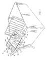
- FIG. 1shows one embodiment of a device made in accordance with the present invention mounted on the handlebar of a shopping cart
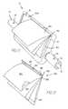
- FIG. 2is a front perspective view of the device of FIG. 1 ;
- FIG. 3is a view taken along the line 3 - 3 of FIG. 2 ;
- FIG. 4is a view taken along the line 4 - 4 of FIG. 2 ;
- FIG. 5is a view taken along the line 5 - 5 of FIG. 2 ;
- FIG. 6is a view taken along the line 6 - 6 of FIG. 2 ;
- FIG. 7is a view taken along the line 7 - 7 of FIG. 2 ;
- FIG. 8is a rear view of the device of FIG. 2 ;
- FIG. 9is a broken-away side perspective view of the device of FIG. 2 ;
- FIG. 10is a broken-away front perspective view of the device of FIG. 2 ;
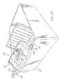
- FIG. 11is a side perspective view of the device of FIG. 2 with a magazine mounted on the device;
- FIG. 12shows a single “flip-up” page of the magazine of FIG. 11 ;
- FIG. 13is a side perspective view of the magazine of FIG. 11 ;
- FIG. 14shows the sheet dispenser of FIG. 1 ;
- FIG. 15shows one of the sheets of FIG. 14 ;
- FIG. 16shows the sheet dispenser of FIG. 14 in the open position
- FIG. 17shows an alternative embodiment of a sheet dispenser for use on the device of FIG. 2 ;
- FIG. 18shows a sheet being removed from the sheet dispenser of FIG. 17 ;
- FIG. 19shows an embodiment of one of the sheets of FIG. 17 ;
- FIG. 20shows an alternate embodiment of a device mounted on a shopping cart
- FIG. 21is a side sectional view showing the device of FIG. 20 .
- FIGS. 1-10show an example of a device 10 for providing visual information on a shopping cart.
- This device 10is mounted on the shopping cart handlebar, and, in this particular embodiment, it holds a coupon dispenser 140 (shown in FIGS. 14 and 17 ), and a magazine 180 (shown in FIG. 13 ). It could alternatively hold other items, such as a display card 221 , shown in FIG. 20 .
- the device 10includes a main body 11 , which defines a central display area 20 , and a right handle 16 and a left handle 18 rigidly attached to and projecting outwardly from the main body 11 .
- the display area 20includes a flat, rectangular backplate 12 and a rectangular frame 14 , which surrounds the periphery of the backplate 12 .
- the frame 14includes a lip 22 , which is spaced above the backplate 12 and extends around the periphery of the backplate 12 .
- the lip 22allows an advertising or display card, magazine, or coupon dispenser to be tucked between the backplate 12 and frame 14 and to be securely held in place.
- the frame 14can also have advertising material or other print adhered to it or printed on it.
- the handles 16 , 18are textured, having a rougher surface than the frame 14 in order to facilitate gripping the handles.
- the body 11could also be textured.
- the handles 16 , 18could also have advertising material printed or adhered on them.
- the handles 16 , 18will be gripped by the shopper in order to push the shopping cart, putting the display area in a good position for being viewed by the shopper.
- the lip 22generally extends around the entire periphery of the backplate 12 .
- there are several pairs of opposed discontinuities 24 in the frame 14which facilitate the insertion of advertising materials onto the backplate 12 .
- the discontinuities 24 Aare located in from the left side of the frame 14 about one-fourth of the width of the entire backplate 12 .
- the discontinuities 24 Bare located in from the right side about one-fourth of the width of the entire backplate 12 .
- the discontinuities in the front and rear frame 14be located in from their respective sides a distance between one-eighth and one-third of the width of the entire backplate. There is no lip (or only a very shallow lip) 22 at the discontinuities 24 .
- the frame 14is connected to the backplate 12 at tabs 28 , and between the tabs 28 there are gaps 26 between the frame 14 and the backplate 12 , where there is no connection between the frame 14 and the backplate 12 .
- the tabs 28are located at some of the discontinuities 24 , but the tabs could be located at other places instead of or in addition to being located at the discontinuities. (See FIGS. 4 and 6 for more detail of the tabs and discontinuities.)
- the discontinuities 24make it easier to install items such as a sheet dispenser, magazine page(s), display cards, etc, and the gaps 26 allow for water drainage, as will be discussed in detail later.
- the backplate 12 and frame 14are connected together only by the tabs 28 that extend outwardly from the backplate 12 in the same plane as the backplate 12 , and that merge with the bottom of the outer edge of the frame 14 at some of the discontinuities 24 A, 24 B.
- a pair of opposed small discontinuities 24 Ctoward the top of the right and left sides of the frame 14 .
- These particular discontinuities 24 Cmake it easier to install a display card 221 (shown in FIG. 20 ), which covers the entire backplate 12 .
- a display card(or other object to be installed) is slid downwardly through the small discontinuities 24 C and beneath the lip 22 .
- FIG. 3is a section through the left side of the body 11 , showing the frame 14 , the backplate 12 , the lip 22 , and a gap 26 .
- FIG. 4is a section through the rear discontinuity 24 A showing the tab 28 which connects the backplate 12 to the frame 14 . This view also shows the discontinuity 24 C and the lip 22 .
- FIG. 5is a section through the rear part of the frame 14 , showing the lip 22 , the discontinuity 24 C, the backplate 12 , and a gap 26 .
- FIG. 6is a section through the front discontinuity 24 B, showing the lip 22 , the tab 28 , the frame 14 , and the backplate 12 .
- FIG. 7is a section view through the front part of the frame 14 , showing the lip 22 , the gap 26 , the frame 14 , and the backplate 12 . It should be noted that the gaps 26 in the forward part of the frame as shown in this figure provide a place for water to drain so that when the shopping cart is exposed to the rain, the water will flow down over the backplate 12 and drain out through the front gaps 26 .
- the handles 16 , 18are rigidly attached to and project outwardly from the right and left sides of the body 11 .
- Both handles 16 , 18have a C-shaped cross section defining an opening 19 that allows them to wrap partially around the handlebar of a standard shopping cart when installed.
- the distance between the ends of the C-shaped opening 19is slightly smaller than the diameter of the shopping cart handlebar 17
- the inside diameter of the cross sectionis slightly larger than the diameter of the shopping cart handlebar 17 so that the handles 16 , 18 open up slightly and then snap into place over the cart handlebar 17 .
- the installerremoves the old handle (if there is one), aligns the handles 16 , 18 with the handlebar 17 of the shopping cart, and simply presses the handles 16 , 18 , downwardly onto the shopping cart handlebar 17 .
- the handles 16 , 18flex sufficiently that the opening 19 opens wide enough to allow the handles 16 , 18 , to snap into place over the handlebar 17 , with the opening 19 returning to its original size once the handles 16 , 18 , have snapped into place.
- the handles 16 , 18need not necessarily snap around the handlebar; alternatively, they could be designed so they would simply rest on top of the handlebar and be secured via screws, clasps, or any other known mounting means.
- the device 10may be installed directly over the existing handle on the shopping cart, without having to remove it to expose the handlebar 17 . Once the device 10 is snapped into place, it may then be screwed onto or otherwise secured to the handlebar 17 , if desired.
- the device 10has holes or partial holes (indentations) 30 , shown in FIGS. 1 , 2 and 8 .
- the holes or indentations 30may be through the handles 16 , 18 or through the backplate 12 or both. Holes or indentations 30 are countersunk to ensure that the screws (or other fasteners) do not project above the backplate 12 or above the handle surface. Partial holes or indentations 30 could be used instead of through holes in order to guide self-tapping screws into the shopping cart handlebar 17 .
- the screws (or other fasteners)secure the device 10 to the handlebar 17 .
- the display area 20 of the device 10is preferably at an acute angle to the horizontal to make it easy for the shopper to see the visual materials mounted on the display area 20 .
- the handles 16 , 18define an imaginary horizontal plane which intersects the edges of the opening 19 , and the display area 20 is at an acute angle to that plane.
- the anglepreferably is between 5 and 70 degrees, and most preferably at approximately 20 degrees to the horizontal as shown in FIG. 1 .
- each platform 32has a concave arcuate bottom surface, which allows it to wrap partially around the handlebar 17 .
- FIGS. 20 and 21show another embodiment of a device 210 made in accordance with the present invention.
- This embodimentdiffers from the previous embodiment in the manner in which it mounts on the shopping cart handlebar 217 .
- the shopping cart handlebardefines two small bars 217 A, 217 B, and the device's handlebars connect in a “clamshell” fashion, clamping over the small bars 217 A, 217 B, which again defines a horizontal plane.
- FIG. 21shows the right handle 216 . It has a top piece 216 A, and a bottom piece 216 B.
- each half of the handle 216contains two concave arcuate surfaces which fit around the handlebars 217 A, 217 B.
- a screw 215is fitted through the hole or indentation 30 to rigidly connect upper and lower halves of the handle 216 .
- other fastening devicesmay be used in place of the screw 215 .
- the left handle 218mounts in the same manner.
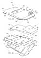
- FIGS. 14 and 16show one embodiment of a sheet dispenser 140 made in accordance with the present invention.
- the sheet dispenser 140includes a housing 142 defining a top wall 144 and a bottom wall 146 .
- the top wall 144has a top surface 145 at a first elevation and a side surface 148 extending downwardly from the top surface 145 and defines a cavity 150 between the top wall 144 and the bottom wall 146 , which houses a plurality of sheets 158 , which have the same shape and are stacked directly on top of each other.
- the top wall 144has a flange 152 projecting outwardly from the side surface 148 at a substantially lower elevation than the first elevation; the flange 152 extends in a direction generally parallel to the top surface 145 and to the bottom wall 146 , and generally perpendicular to the side surface 148 .
- the flange 152projects outwardly from the side surface 148 along front, rear, left and right side portions, surrounds the periphery of the cavity, and forms the outermost edge of the housing 142 .
- the flange 152fits beneath the lip 22 , while the bottom wall 146 rests on the backplate 12 , as will be explained in more detail later.
- the entire housingis made as one piece of clear plastic material which flexes on the right side to form a hinge 160 .
- the flange portion 152 and the edge of the bottom wall 146have flexible flaps 156 , which interlock as shown in FIG. 14 to hold the housing in the closed position.
- the dispenser 140may open (as in FIG. 14 ) and close (as in FIG. 16 ). When in the closed position (as in FIG. 14 ), these flaps 156 act as a locking mechanism.
- the opening 154 in the top surface 145for the removal of sheets 158 stored in the cavity 150 .
- the openingis large enough to permit a human finger to fit into it and wide enough to permit the full width of the sheets to pass through without buckling.
- the sheets 158may be coupons, recipes, or any other visual or textual information that the shopper may want to take from the cart.
- These sheets 158are made of polypropylene or some other synthetic polymeric material that is both flexible and waterproof. Water can escape the cavity 150 through the space between the flange 152 of the top wall 144 and the bottom wall 146 , and can continue through the gap 26 out of the device 10 altogether.
- each sheet 158 in the stackis an elongated, rectangular member, having an elongated direction and being folded back on itself twice along folds 159 that are perpendicular to the elongated direction.
- the lower layers 158 B and 158 Cextend substantially the full length of the cavity 150 , while the top layer 158 A extends only part of the length of the cavity, terminating at an end 155 , which is aligned with the opening 154 .
- the userneed only reach into the cavity end 150 through the opening 154 and pull on the sheet 158 until the sheet slides out of the cavity 150 through the opening 154 .
- the sheet 158will unfold as it is pulled out.
- the next sheet 158 in the stackis left in proper position to be similarly removed.
- the sheets 158may be provided pre-packaged in the sheet dispenser.
- the usersimply disposes of the sheet dispenser 140 and installs a new sheet dispenser full of sheets. This saves the trouble of installing additional sheets into the empty dispenser.
- thiscould be done by separating the interlocking flaps 156 by pulling up on the flange portion 152 of the top wall 144 and pulling down on the corresponding edge of the bottom wall 146 , inserting sheets 158 into the cavity 150 , and re-closing by re-interlocking the flaps as is best shown in FIG. 14 .
- FIG. 17shows another embodiment of a sheet dispenser 240 .
- this sheet dispenser 240includes a bottom wall 246 as well as a top wall 244 having a top surface 245 , a side surface 248 , and a flange portion 252 . It also includes a sheet removal opening 254 .
- the opening 254is “T”-shaped. (Obviously, other shapes of openings could be used instead.)
- the T-slotis wide enough to receive a human finger.
- the userinserts a finger into the central leg of the “T” and slides the sheet 258 forward, causing the sheet 258 to buckle enough in the width-wise direction to be gripped between thumb and forefinger, and thereby be removed.
- This embodimentunlike the previous sheet dispenser 140 , does not have flaps 156 for potential interlocking and closure; however it is also made of one piece of flexible, strong material (preferably plastic, though other materials could be used) and includes a live hinge 260 as in the previous embodiment.
- the flange 252 of the top wall 244is adhered to the bottom wall 246 using a heat-sealing process, which retains the housing in the closed position.
- Alternatively, other forms of adhesivescould be used.
- the heat sealwould not necessarily have to extend around the entire periphery of the dispenser 240 ; preferably the lower edge would be left unsealed to allow for water to drain out as in the previous embodiment.
- This embodimentis better suited to be used as a disposable, pre-packaged sheet dispenser than to being refilled.
- FIG. 11shows the device 10 prior to installation of the sheet dispenser.
- a magazine 180(which will be described in detail later) has already been installed on the right side of the device 10 , and the sheet dispenser 140 should be aligned for installation on the left side of the device. Such placement can be seen in FIG. 1 .
- the magazine 180could be placed on the left, and the sheet dispenser 140 could be installed on the right, and other combinations, such as a dispenser and a card could be used as well.
- the top edge of the flange 152is slid leftwardly under the upper lip 22 through the discontinuity 24 A at the rear of the device, and the bottom edge of the flange 152 is slid leftwardly under the lower lip 22 through the discontinuity 24 A at the front of the device and is pushed to the left until the left edge of the flange 152 is under the left lip 22 .
- the right edge of the flange 152may be tucked underneath the magazine 180 . Even if it is not tucked, however, the sheet dispenser 140 will not slide rightwardly out of device 10 , because its top right corner will abut the edge of the discontinuity 24 A. Thus, the sheet dispenser 140 is secured on all four sides.
- the sheet dispenser 140 or 240is not easily dislodged in normal use, but it can be removed from the device whenever necessary to insert a new dispenser containing a new pack of sheets.
- the back of the sheet dispenser 140could be adhered to the device 10 with adhesive (not shown), if desired.
- the top page of the magazine 180is advertising a particular product
- the sheets 158are coupons which provide a discount for the same product.
- this devicepermits the store to provide fixed, in-store advertising and removable coupons for the same product on the shopping cart, which is very convenient for the shopper.
- the sheets 158do not necessarily have to be coupons which match the magazine 180 .
- the sheets 158could also be announcements, recipes, schedules of in-store TV or radio, or any other graphics or text.
- FIG. 13shows one embodiment of a magazine 180 designed to be inserted into the device 10 , as shown in FIGS. 1 and 11 .
- the basic components of the magazine 180are a rear sheet 182 , a spine 186 , a live hinge 188 , and a top page or plurality of pages 184 .
- the rear sheet 182is flat and bendable and extends slightly beyond the pages 184 on its bottom edge so that its bottom edge may be tucked under the bottom lip 22 in the device 10 while the edges of the pages 184 are free of the lip 22 and can be opened and closed freely.
- the pages 184are made of paper or card stock that has been laminated.
- the paper or card stockmay be made of wood fibers, but it preferably is made of a synthetic polymeric material, such as polypropylene, that is waterproof so it is not necessary to have a complete seal around it.
- the pages 184are bound to the rear sheet 182 at the spine 186 , as shown in FIG. 13 .
- the pages 184 and rear sheet 182are stapled together with staples 190 .
- the pagescould alternatively be glued, stitched, clamped, or bound by other known means to the rear sheet 182 .
- the bindingis thin enough that it can fit under the top lip 22 to help secure the magazine 180 to the device 10 .
- the pages 184 shown in FIGS. 11-13are blank, but the magazine actually contains pages of printed information, which may include text and pictures, as shown in FIG. 1 .
- the information in the magazinecould include advertisements, shopping tips, in-store specials, a store directory, a schedule of in-store TV or radio programs, recipes, and the like.
- each pageincludes a live hinge 188 , as described above.
- the pagesbend at the thinner, more flexible laminate strip portion 188 rather than at the thicker, more rigid card portions.
- the spine 186itself contains cardstock, paper, or other stiffening material to create a solid surface to attach staples (or other fastening devices) 186 , and to create a stronger grip when the spine 186 is installed under the top lip 22 of the device 10 .
- the live hinge 188is firmly secured to the printed portion of the page, and it provides a place for the pages to bend or fold easily.
- the rear page 182further contains an extended flap of the cardstock above the stapled spine 186 .
- the cardstock(and the whole back page) may or may not be laminated. If it is not laminated, it should be made of a waterproof material.
- This flap 192folds back over the top of the spine 186 , creating extra thickness to facilitate a strong connection between the magazine 180 and the device 10 as the spine 186 is tucked under the rear lip 22 .
- the laminatemay be vinyl, polyester, polypropylene, nylon, or the like, and it is preferable for the laminate to be clear in order to readily view the material on the paper or cardstock.
- the magazine 180 , the sheet dispenser 140 , the sheets 158 , and the device 10are waterproof, as shopping carts are frequently exposed to the various weather elements.
- FIG. 11shows the magazine 180 after it is inserted into the device 10 .
- the flap 192has been folded over the spine 186 , and the spine 186 , covered with the flap 192 , has been inserted under the rear lip 22 .
- Making the spine 186 the correct size and shape so it can be inserted under the rear lip 22 and inserting the spine 186 under the rear lip 22provides one means of fixing the magazine relative to the back plate 12 .
- the bottom edge of the rear sheet 182has been inserted under the front lip 22 . This provides another means of fixing the magazine relative to the back plate 12 .
- the bottom edges of the pages 184terminate short of the front lip 22 , so that the pages 184 can be flipped up to view.
- Fixing the magazine relative to the backplate with the pages terminating short of the lip 22 so the pages are not trapped under the lip 22provides a means for opening the magazine and accessing the full surface area of the pages up to the spine from the front of the body while the magazine is fixed relative to the backplate.
- the pages 184fit neatly into the recessed central display area 20 defined by the frame 14 and backplate 12 .
- the magazinedoes not fill the entire width of the backplate 12 in order to leave room for additional advertising materials.
- the additional space to the left of the magazine 180is being used for the sheet dispenser 140 as shown in FIG. 1 .
- the magazinecould extend across the entire width of the frame, if desired.
- one or more adhesive stripsmay be used to secure the rear of the magazine 180 and/or coupon dispenser 140 to the device 10 .
- Thisprovides another means for fixing the magazine 180 relative to the back plate.
- the adhesive stripcan be placed on the central portion of the rear face of the rear sheet 182 of the magazine or on the back surface of the sheet dispenser 140 , adhering it to the backplate 12 .
- the adhesive stripmay conveniently be provided on the back of the magazine 180 or sheet dispenser 140 with a peel-off cover strip that can simply be removed when one is installing the magazine 180 or sheet dispenser onto the device 10 .
- each page 184is free to be flipped open, and the full surface area of each page up to the spine can be accessed from the front of the device 10 while the magazine is fixed on the backplate.
- FIG. 1shows the magazine 180 inserted alongside a sheet dispenser 140 .
- the sheet dispenser 140is mounted with its right flange beneath the rear page of the magazine.
- a major advantage of this deviceis that it allows for interactivity between advertisers and customers. For example, shoppers can see an advertisement for an item on a magazine or card mounted on the device 10 and then pick up a corresponding coupon from the sheet dispenser also mounted on the device 10 . Shoppers can use store directories and maps on a magazine or card mounted on the device 10 to locate goods (or services) more conveniently. Additionally, this product offers the opportunity for interactivity between the display on the shopping cart and other materials in the store, such as in-store TV or radio programs. For example, an in-store TV may have a program on cooking a particular recipe every hour at ten minutes after the hour.
- Shopperscan learn about this segment and when to watch it by reading an in-store TV schedule printed in the magazine portion of the display 10 , then watch the corresponding program, and, if interested, take the recipe from the sheet dispenser and purchase the required ingredients all in one trip to the store.
- an in-store radio or television programmay refer the shopper to his on-cart display device 10 for recipes, coupons, in-store specials, instructions, or other types of information.
Landscapes
- Engineering & Computer Science (AREA)
- Chemical & Material Sciences (AREA)
- Combustion & Propulsion (AREA)
- Transportation (AREA)
- Mechanical Engineering (AREA)
- Physics & Mathematics (AREA)
- General Physics & Mathematics (AREA)
- Theoretical Computer Science (AREA)
- Handcart (AREA)
- Cash Registers Or Receiving Machines (AREA)
- Management, Administration, Business Operations System, And Electronic Commerce (AREA)
Abstract
Description
Claims (15)
Priority Applications (4)
| Application Number | Priority Date | Filing Date | Title |
|---|---|---|---|
| US11/458,524US7895777B2 (en) | 2005-07-29 | 2006-07-19 | Shopping cart device |
| US11/773,783US7681344B2 (en) | 2005-07-29 | 2007-07-05 | Shopping cart device |
| US13/006,028US20110131846A1 (en) | 2005-07-29 | 2011-01-13 | Shopping cart device |
| US13/112,644US20110221149A1 (en) | 2005-07-29 | 2011-05-20 | Shopping cart device |
Applications Claiming Priority (4)
| Application Number | Priority Date | Filing Date | Title |
|---|---|---|---|
| US59571405P | 2005-07-29 | 2005-07-29 | |
| US59587705P | 2005-08-12 | 2005-08-12 | |
| US74463406P | 2006-04-11 | 2006-04-11 | |
| US11/458,524US7895777B2 (en) | 2005-07-29 | 2006-07-19 | Shopping cart device |
Related Child Applications (3)
| Application Number | Title | Priority Date | Filing Date |
|---|---|---|---|
| US11/773,783Continuation-In-PartUS7681344B2 (en) | 2005-07-29 | 2007-07-05 | Shopping cart device |
| US13/006,028ContinuationUS20110131846A1 (en) | 2005-07-29 | 2011-01-13 | Shopping cart device |
| US13/006,028Continuation-In-PartUS20110131846A1 (en) | 2005-07-29 | 2011-01-13 | Shopping cart device |
Publications (2)
| Publication Number | Publication Date |
|---|---|
| US20060266904A1 US20060266904A1 (en) | 2006-11-30 |
| US7895777B2true US7895777B2 (en) | 2011-03-01 |
Family
ID=37635747
Family Applications (1)
| Application Number | Title | Priority Date | Filing Date |
|---|---|---|---|
| US11/458,524Expired - Fee RelatedUS7895777B2 (en) | 2005-07-29 | 2006-07-19 | Shopping cart device |
Country Status (5)
| Country | Link |
|---|---|
| US (1) | US7895777B2 (en) |
| EP (1) | EP1911012B1 (en) |
| AT (1) | ATE511175T1 (en) |
| ES (1) | ES2363440T3 (en) |
| WO (1) | WO2007015874A2 (en) |
Cited By (12)
| Publication number | Priority date | Publication date | Assignee | Title |
|---|---|---|---|---|
| US20110131846A1 (en)* | 2005-07-29 | 2011-06-09 | Cart-Tv, Llc | Shopping cart device |
| US20110221149A1 (en)* | 2005-07-29 | 2011-09-15 | Bryan Eugene Crum | Shopping cart device |
| USD701862S1 (en)* | 2011-02-18 | 2014-04-01 | Lg Electronics Inc. | Cart barcode scanner |
| US9126616B2 (en) | 2013-10-18 | 2015-09-08 | Bryan E. Crum | Shopping cart attachment |
| US20160207557A1 (en)* | 2012-10-11 | 2016-07-21 | Gals Shopper Llc | Shopping list attachment and holder for a shopping cart or basket |
| US10179599B1 (en) | 2017-08-09 | 2019-01-15 | Russell Lee Lambrecht | Paper and/or phone holder accessory for a shopping cart |
| US10286939B2 (en) | 2017-05-18 | 2019-05-14 | Walmart Apollo, Llc | Shopping cart with scanner system |
| US10308269B2 (en) | 2017-06-08 | 2019-06-04 | Walmart Apollo, Llc | Shopping cart with sensor system |
| US10438271B2 (en) | 2007-03-26 | 2019-10-08 | Media Cart Holdings, Inc. | Integration of customer-stored information with media enabled shopping systems |
| USD905370S1 (en)* | 2019-02-07 | 2020-12-15 | Target Brands, Inc. | Cart handle |
| US10949910B2 (en) | 2007-03-26 | 2021-03-16 | Media Cart Holdings, Inc. | Media enhanced shopping systems with data mining functionalities |
| US11046346B2 (en)* | 2017-03-02 | 2021-06-29 | Wanzl GmbH & Co. KGaA | Push handle unit |
Families Citing this family (18)
| Publication number | Priority date | Publication date | Assignee | Title |
|---|---|---|---|---|
| US7660747B2 (en) | 2005-06-28 | 2010-02-09 | Media Cart Holdings, Inc. | Media enabled shopping cart system with point of sale identification and method |
| US7443295B2 (en) | 2005-06-28 | 2008-10-28 | Media Cart Holdings, Inc. | Media enabled advertising shopping cart system |
| US7679522B2 (en) | 2007-03-26 | 2010-03-16 | Media Cart Holdings, Inc. | Media enhanced shopping systems with electronic queuing |
| US7762458B2 (en) | 2007-03-25 | 2010-07-27 | Media Cart Holdings, Inc. | Media enabled shopping system user interface |
| US7714723B2 (en) | 2007-03-25 | 2010-05-11 | Media Cart Holdings, Inc. | RFID dense reader/automatic gain control |
| US7741808B2 (en) | 2007-03-25 | 2010-06-22 | Media Cart Holdings, Inc. | Bi-directional charging/integrated power management unit |
| US7782194B2 (en) | 2007-03-25 | 2010-08-24 | Media Cart Holdings, Inc. | Cart coordinator/deployment manager |
| US20120123826A1 (en)* | 2007-09-13 | 2012-05-17 | French John R | Shopping Cart Accountability Using Coupon Incentives with Participation Option |
| US20090076895A1 (en)* | 2007-09-13 | 2009-03-19 | French John R | Shopping cart accountability using coupon incentives |
| SE0702388L (en)* | 2007-10-29 | 2009-02-24 | Memonote Ab | exposure device |
| US20090199360A1 (en)* | 2008-02-07 | 2009-08-13 | Madanat Azmie K | Cart Handle Dispenser |
| WO2010033680A1 (en)* | 2008-09-19 | 2010-03-25 | Engage In-Store, LLC | Electronic device for shopping cart |
| US20110258897A1 (en)* | 2010-04-23 | 2011-10-27 | B2B Media, LLC | Frame Systems for Signage and Methods Relating Thereto |
| CN102339504B (en)* | 2011-04-14 | 2014-08-20 | 盛骏 | Commodity wireless data acquisition, verification and settlement cart device and verification and settlement method thereof |
| CN203713943U (en)* | 2014-02-18 | 2014-07-16 | 无锡知谷网络科技有限公司 | Handcart |
| CN108665795A (en)* | 2017-03-31 | 2018-10-16 | 北京微泊科技有限公司 | It is a kind of to show knob ad system for subway and the smart electronics of public transport |
| CN111267933A (en)* | 2020-02-29 | 2020-06-12 | 胡夏妹 | Intelligent shopping cart robot |
| US12246894B1 (en)* | 2021-05-26 | 2025-03-11 | Raul Rodriguez, Jr. | Container having lid with outwardly facing display panel |
Citations (51)
| Publication number | Priority date | Publication date | Assignee | Title |
|---|---|---|---|---|
| US2864189A (en) | 1957-06-28 | 1958-12-16 | Owen Morgan And Niland | Shopping aid sheet holders for pushcarts |
| US2888761A (en) | 1958-04-21 | 1959-06-02 | James G Miller | Directory and clip board combination |
| US3082557A (en) | 1962-01-02 | 1963-03-26 | Cart Ads Corp | Advertising display board |
| US3251543A (en) | 1965-05-03 | 1966-05-17 | Fred L Bush | Shopping cart attachment |
| US3964134A (en) | 1975-03-10 | 1976-06-22 | Newtson Gary L | Grocery cart clip attachment |
| US3982659A (en)* | 1975-12-24 | 1976-09-28 | Scott Paper Company | Bulk package for substantially wet sheets and dispensing device therefor |
| US4292749A (en) | 1980-05-19 | 1981-10-06 | Thomas Claude E | Display device for coupon clip |
| US4496058A (en) | 1983-06-01 | 1985-01-29 | Harris Garrett R | Shopping organizer |
| US4535912A (en)* | 1973-10-11 | 1985-08-20 | Colgate-Palmolive Company | Pre-moistened towelette dispenser |
| US4583753A (en) | 1984-07-19 | 1986-04-22 | Economy Charles G | Desk attachment for shopping cart |
| GB2176332A (en) | 1985-06-04 | 1986-12-17 | Calcumate | Shopping aids |
| US4685701A (en) | 1986-07-16 | 1987-08-11 | Amundson Anita L | Shopping cart caddy |
| BR6602284U (en) | 1986-11-20 | 1988-06-28 | Luiz Paulo Bendl | DIRECT ADVERTISING VEHICLE |
| US4848117A (en) | 1987-05-08 | 1989-07-18 | Welborn Woodrow W | Shopping cart list holder |
| US4901901A (en) | 1989-02-13 | 1990-02-20 | Reitenour Peggy B | Shopping cart desk |
| US4988025A (en) | 1989-12-14 | 1991-01-29 | R. J. Reynolds Tobacco Company | Shopping cart attachment |
| US5002215A (en) | 1990-03-09 | 1991-03-26 | Gregoire Joseph R | Portable shopping cart coupon file and method of utilizing same for shopping |
| US5004252A (en) | 1989-07-24 | 1991-04-02 | Wayne Kraper | Shopping basket accessory |
| US5038986A (en) | 1990-03-23 | 1991-08-13 | Beauchesne Dorothy A | Coupon organizer |
| US5048736A (en) | 1990-06-26 | 1991-09-17 | Anatra Enterprises, Inc. | Coupon holder |
| WO1992000560A1 (en) | 1990-06-29 | 1992-01-09 | Luminis Pty. Ltd. | A generalised systolic array serial floating point adder and accumulator |
| US5086960A (en) | 1990-12-31 | 1992-02-11 | Janet Schwietzer | Grocery cart attachment |
| US5263578A (en) | 1992-08-24 | 1993-11-23 | Narvey Diane M | Coupon holder container |
| US5305935A (en) | 1992-09-29 | 1994-04-26 | Weiner Andrea L | Coupon organizer |
| FR2713004A1 (en) | 1993-11-26 | 1995-06-02 | Collet Pierre | Advertisement holder for handle of supermarket trolley |
| US5424524A (en) | 1993-06-24 | 1995-06-13 | Ruppert; Jonathan P. | Personal scanner/computer for displaying shopping lists and scanning barcodes to aid shoppers |
| US5429377A (en) | 1993-04-15 | 1995-07-04 | Duer; Sandra D. | Sanitary protective covers for shopping cart use |
| US5489120A (en) | 1994-12-05 | 1996-02-06 | Thornsburg; Bettie A. | Coupon organizer |
| WO1996011130A1 (en) | 1994-10-07 | 1996-04-18 | Myers, Lorraine, Patricia | Trolley handle unit |
| US5566609A (en) | 1995-11-24 | 1996-10-22 | Kirschner; Suzanne | Shopping cart clipboard and coupon holder |
| US5597104A (en) | 1995-09-15 | 1997-01-28 | Charles Domen | Disposable coupon holder for a shopping cart |
| US5617982A (en) | 1993-12-14 | 1997-04-08 | Wilson; Paul A. | Coupon holder and dispensing apparatus |
| WO1997021207A1 (en) | 1995-12-07 | 1997-06-12 | Ramos Pinera Pascual | Support for publicity and shopping lists, applicable to supermarket trolleys |
| AT1523U2 (en) | 1996-09-13 | 1997-06-25 | Schwimmer Viktor Mag | DEVICE FOR ATTACHING INFORMATION OR ADVERTISING MATERIAL TO A SHOPPING CART |
| US5848723A (en)* | 1996-09-26 | 1998-12-15 | Krautsack; Richard G. | Foldable coupon dispenser |
| EP0895920A1 (en) | 1997-08-06 | 1999-02-10 | Oechsle Kunststofftechnik GmbH | Advisory display board removably mounted on the handle bar of a shopping trolley |
| USD405820S (en)* | 1991-10-18 | 1999-02-16 | Larson Karen L | Shopper's mate |
| US6000610A (en)* | 1993-02-26 | 1999-12-14 | Talbott; Theresa G. | Store specific shopping system and method including a map/shopping list |
| US6158640A (en) | 1998-11-25 | 2000-12-12 | Hands-On-Media L.L.C. | Elongated shopping cart attachment having opposing tongues |
| US6177880B1 (en) | 1992-01-16 | 2001-01-23 | Klever-Kart, Inc. | Automated shopping cart handle |
| DE19955074A1 (en) | 1999-11-15 | 2001-05-17 | Systec Pos Technology Gmbh | Shopping trolley has push bar with advertising surface carrying hologram etc. visible from different angles |
| US6284177B1 (en)* | 1996-10-15 | 2001-09-04 | William D. Ewing | Recyclable printable media |
| US6299119B1 (en) | 1999-12-22 | 2001-10-09 | David J. Dunning | Notepad attachment apparatus |
| US20020070141A1 (en)* | 2000-12-08 | 2002-06-13 | Uni-Charm Corporation | Sheet package |
| US6453588B1 (en)* | 2000-03-27 | 2002-09-24 | Thomas B. Lykens | Magnetically receptive shopping cart carrier plate |
| US6584712B2 (en) | 2001-01-02 | 2003-07-01 | Floorgraphics, Inc. | Shopping cart display device |
| GB2386354A (en) | 2002-03-15 | 2003-09-17 | Myers Lorraine Patricia | Trolley handle |
| US20040069918A1 (en) | 2002-10-08 | 2004-04-15 | Realaid, Inc. | Shopping display an writing surface assistant |
| CA2459153A1 (en) | 2003-04-28 | 2004-10-28 | Dennis Garberg & Associates, Inc. | Mobile dispensing display, method for conversion of shopping cart into dispensing display and method of advertising and dispensing products |
| US6898884B1 (en)* | 2002-10-25 | 2005-05-31 | Darko, Inc. | Point of purchase display system |
| WO2006117627A1 (en) | 2005-04-29 | 2006-11-09 | Springboard Retail Networks Licensing Srl | Electronic shopping cart handle |
Family Cites Families (1)
| Publication number | Priority date | Publication date | Assignee | Title |
|---|---|---|---|---|
| US5306935A (en)* | 1988-12-21 | 1994-04-26 | Texas Instruments Incorporated | Method of forming a nonvolatile stacked memory |
- 2006
- 2006-07-19EPEP06787738Apatent/EP1911012B1/ennot_activeNot-in-force
- 2006-07-19ATAT06787738Tpatent/ATE511175T1/ennot_activeIP Right Cessation
- 2006-07-19WOPCT/US2006/027887patent/WO2007015874A2/enactiveApplication Filing
- 2006-07-19ESES06787738Tpatent/ES2363440T3/enactiveActive
- 2006-07-19USUS11/458,524patent/US7895777B2/ennot_activeExpired - Fee Related
Patent Citations (52)
| Publication number | Priority date | Publication date | Assignee | Title |
|---|---|---|---|---|
| US2864189A (en) | 1957-06-28 | 1958-12-16 | Owen Morgan And Niland | Shopping aid sheet holders for pushcarts |
| US2888761A (en) | 1958-04-21 | 1959-06-02 | James G Miller | Directory and clip board combination |
| US3082557A (en) | 1962-01-02 | 1963-03-26 | Cart Ads Corp | Advertising display board |
| US3251543A (en) | 1965-05-03 | 1966-05-17 | Fred L Bush | Shopping cart attachment |
| US4535912A (en)* | 1973-10-11 | 1985-08-20 | Colgate-Palmolive Company | Pre-moistened towelette dispenser |
| US3964134A (en) | 1975-03-10 | 1976-06-22 | Newtson Gary L | Grocery cart clip attachment |
| US3982659A (en)* | 1975-12-24 | 1976-09-28 | Scott Paper Company | Bulk package for substantially wet sheets and dispensing device therefor |
| US4292749A (en) | 1980-05-19 | 1981-10-06 | Thomas Claude E | Display device for coupon clip |
| US4496058A (en) | 1983-06-01 | 1985-01-29 | Harris Garrett R | Shopping organizer |
| US4583753A (en) | 1984-07-19 | 1986-04-22 | Economy Charles G | Desk attachment for shopping cart |
| GB2176332A (en) | 1985-06-04 | 1986-12-17 | Calcumate | Shopping aids |
| US4685701A (en) | 1986-07-16 | 1987-08-11 | Amundson Anita L | Shopping cart caddy |
| BR6602284U (en) | 1986-11-20 | 1988-06-28 | Luiz Paulo Bendl | DIRECT ADVERTISING VEHICLE |
| US4848117A (en) | 1987-05-08 | 1989-07-18 | Welborn Woodrow W | Shopping cart list holder |
| US4901901A (en) | 1989-02-13 | 1990-02-20 | Reitenour Peggy B | Shopping cart desk |
| US5004252A (en) | 1989-07-24 | 1991-04-02 | Wayne Kraper | Shopping basket accessory |
| US4988025A (en) | 1989-12-14 | 1991-01-29 | R. J. Reynolds Tobacco Company | Shopping cart attachment |
| US5002215A (en) | 1990-03-09 | 1991-03-26 | Gregoire Joseph R | Portable shopping cart coupon file and method of utilizing same for shopping |
| US5038986A (en) | 1990-03-23 | 1991-08-13 | Beauchesne Dorothy A | Coupon organizer |
| US5048736A (en) | 1990-06-26 | 1991-09-17 | Anatra Enterprises, Inc. | Coupon holder |
| WO1992000560A1 (en) | 1990-06-29 | 1992-01-09 | Luminis Pty. Ltd. | A generalised systolic array serial floating point adder and accumulator |
| US5086960A (en) | 1990-12-31 | 1992-02-11 | Janet Schwietzer | Grocery cart attachment |
| USD405820S (en)* | 1991-10-18 | 1999-02-16 | Larson Karen L | Shopper's mate |
| US6177880B1 (en) | 1992-01-16 | 2001-01-23 | Klever-Kart, Inc. | Automated shopping cart handle |
| US5263578A (en) | 1992-08-24 | 1993-11-23 | Narvey Diane M | Coupon holder container |
| US5305935A (en) | 1992-09-29 | 1994-04-26 | Weiner Andrea L | Coupon organizer |
| US6000610A (en)* | 1993-02-26 | 1999-12-14 | Talbott; Theresa G. | Store specific shopping system and method including a map/shopping list |
| US5429377A (en) | 1993-04-15 | 1995-07-04 | Duer; Sandra D. | Sanitary protective covers for shopping cart use |
| US5424524A (en) | 1993-06-24 | 1995-06-13 | Ruppert; Jonathan P. | Personal scanner/computer for displaying shopping lists and scanning barcodes to aid shoppers |
| FR2713004A1 (en) | 1993-11-26 | 1995-06-02 | Collet Pierre | Advertisement holder for handle of supermarket trolley |
| US5617982A (en) | 1993-12-14 | 1997-04-08 | Wilson; Paul A. | Coupon holder and dispensing apparatus |
| WO1996011130A1 (en) | 1994-10-07 | 1996-04-18 | Myers, Lorraine, Patricia | Trolley handle unit |
| US5836051A (en)* | 1994-10-07 | 1998-11-17 | Myers; Robert | Trolley handle unit |
| US5489120A (en) | 1994-12-05 | 1996-02-06 | Thornsburg; Bettie A. | Coupon organizer |
| US5597104A (en) | 1995-09-15 | 1997-01-28 | Charles Domen | Disposable coupon holder for a shopping cart |
| US5566609A (en) | 1995-11-24 | 1996-10-22 | Kirschner; Suzanne | Shopping cart clipboard and coupon holder |
| WO1997021207A1 (en) | 1995-12-07 | 1997-06-12 | Ramos Pinera Pascual | Support for publicity and shopping lists, applicable to supermarket trolleys |
| AT1523U2 (en) | 1996-09-13 | 1997-06-25 | Schwimmer Viktor Mag | DEVICE FOR ATTACHING INFORMATION OR ADVERTISING MATERIAL TO A SHOPPING CART |
| US5848723A (en)* | 1996-09-26 | 1998-12-15 | Krautsack; Richard G. | Foldable coupon dispenser |
| US6284177B1 (en)* | 1996-10-15 | 2001-09-04 | William D. Ewing | Recyclable printable media |
| EP0895920A1 (en) | 1997-08-06 | 1999-02-10 | Oechsle Kunststofftechnik GmbH | Advisory display board removably mounted on the handle bar of a shopping trolley |
| US6158640A (en) | 1998-11-25 | 2000-12-12 | Hands-On-Media L.L.C. | Elongated shopping cart attachment having opposing tongues |
| DE19955074A1 (en) | 1999-11-15 | 2001-05-17 | Systec Pos Technology Gmbh | Shopping trolley has push bar with advertising surface carrying hologram etc. visible from different angles |
| US6299119B1 (en) | 1999-12-22 | 2001-10-09 | David J. Dunning | Notepad attachment apparatus |
| US6453588B1 (en)* | 2000-03-27 | 2002-09-24 | Thomas B. Lykens | Magnetically receptive shopping cart carrier plate |
| US20020070141A1 (en)* | 2000-12-08 | 2002-06-13 | Uni-Charm Corporation | Sheet package |
| US6584712B2 (en) | 2001-01-02 | 2003-07-01 | Floorgraphics, Inc. | Shopping cart display device |
| GB2386354A (en) | 2002-03-15 | 2003-09-17 | Myers Lorraine Patricia | Trolley handle |
| US20040069918A1 (en) | 2002-10-08 | 2004-04-15 | Realaid, Inc. | Shopping display an writing surface assistant |
| US6898884B1 (en)* | 2002-10-25 | 2005-05-31 | Darko, Inc. | Point of purchase display system |
| CA2459153A1 (en) | 2003-04-28 | 2004-10-28 | Dennis Garberg & Associates, Inc. | Mobile dispensing display, method for conversion of shopping cart into dispensing display and method of advertising and dispensing products |
| WO2006117627A1 (en) | 2005-04-29 | 2006-11-09 | Springboard Retail Networks Licensing Srl | Electronic shopping cart handle |
Cited By (16)
| Publication number | Priority date | Publication date | Assignee | Title |
|---|---|---|---|---|
| US20110221149A1 (en)* | 2005-07-29 | 2011-09-15 | Bryan Eugene Crum | Shopping cart device |
| US20110131846A1 (en)* | 2005-07-29 | 2011-06-09 | Cart-Tv, Llc | Shopping cart device |
| US10949910B2 (en) | 2007-03-26 | 2021-03-16 | Media Cart Holdings, Inc. | Media enhanced shopping systems with data mining functionalities |
| US12229819B2 (en) | 2007-03-26 | 2025-02-18 | Media Cart Holdings, Inc. | Integration of customer-stored information with media enabled shopping systems |
| US11983760B2 (en) | 2007-03-26 | 2024-05-14 | Media Cart Holdings, Inc. | Media enhanced shopping systems with data mining functionalities |
| US11538090B2 (en) | 2007-03-26 | 2022-12-27 | Media Cart Holdings, Inc. | Media enhanced shopping systems with data mining functionalities |
| US10438271B2 (en) | 2007-03-26 | 2019-10-08 | Media Cart Holdings, Inc. | Integration of customer-stored information with media enabled shopping systems |
| USD701862S1 (en)* | 2011-02-18 | 2014-04-01 | Lg Electronics Inc. | Cart barcode scanner |
| US20160207557A1 (en)* | 2012-10-11 | 2016-07-21 | Gals Shopper Llc | Shopping list attachment and holder for a shopping cart or basket |
| US9771094B2 (en)* | 2012-10-11 | 2017-09-26 | Gals Shopper Llc | Shopping list attachment and holder for a shopping cart or basket |
| US9126616B2 (en) | 2013-10-18 | 2015-09-08 | Bryan E. Crum | Shopping cart attachment |
| US11046346B2 (en)* | 2017-03-02 | 2021-06-29 | Wanzl GmbH & Co. KGaA | Push handle unit |
| US10286939B2 (en) | 2017-05-18 | 2019-05-14 | Walmart Apollo, Llc | Shopping cart with scanner system |
| US10308269B2 (en) | 2017-06-08 | 2019-06-04 | Walmart Apollo, Llc | Shopping cart with sensor system |
| US10179599B1 (en) | 2017-08-09 | 2019-01-15 | Russell Lee Lambrecht | Paper and/or phone holder accessory for a shopping cart |
| USD905370S1 (en)* | 2019-02-07 | 2020-12-15 | Target Brands, Inc. | Cart handle |
Also Published As
| Publication number | Publication date |
|---|---|
| ATE511175T1 (en) | 2011-06-15 |
| WO2007015874A3 (en) | 2007-04-05 |
| EP1911012B1 (en) | 2011-05-25 |
| WO2007015874A2 (en) | 2007-02-08 |
| ES2363440T3 (en) | 2011-08-04 |
| US20060266904A1 (en) | 2006-11-30 |
| EP1911012A2 (en) | 2008-04-16 |
Similar Documents
| Publication | Publication Date | Title |
|---|---|---|
| US7895777B2 (en) | Shopping cart device | |
| US7681344B2 (en) | Shopping cart device | |
| US20110221149A1 (en) | Shopping cart device | |
| US5608949A (en) | Fastenable bag closure | |
| JP3899382B2 (en) | Compressible sheet dispenser | |
| US7823927B2 (en) | Media binder systems with datum stops for registering physical media sheets | |
| RU2176413C2 (en) | Self-adhesive label | |
| US5282534A (en) | Combined product package and coupon delivery system | |
| US20050022437A1 (en) | Movable advertising display system and method | |
| EP0469116A1 (en) | Recyclable package. | |
| US6669392B2 (en) | Device for binding sheets and bound sheets | |
| US6745509B1 (en) | Integrated coupon dispenser and promotional signage product | |
| US20110131846A1 (en) | Shopping cart device | |
| US20050103659A1 (en) | Means of attaching rigid pages to a book-like cover | |
| US6851572B2 (en) | Dispenser box | |
| US20110259507A1 (en) | Personalizable Calendar Assemblies and Methods | |
| US5568898A (en) | Wrap around label | |
| JPH0712315Y2 (en) | cover | |
| JPH074053U (en) | Book | |
| JP3098980U (en) | Paper dispenser | |
| JP2521586Y2 (en) | Exhibition equipment | |
| JP3376324B2 (en) | Video case for rental shop | |
| JPH0710760U (en) | Exhibit | |
| JPH0642773U (en) | cover | |
| JPH0657849U (en) | cover |
Legal Events
| Date | Code | Title | Description |
|---|---|---|---|
| AS | Assignment | Owner name:CMR INVESTMENTS, LLC, KENTUCKY Free format text:ASSIGNMENT OF ASSIGNORS INTEREST;ASSIGNOR:CRUM, BRIAN;REEL/FRAME:017960/0804 Effective date:20060719 | |
| AS | Assignment | Owner name:CART-TV, LLC, KENTUCKY Free format text:ASSIGNMENT OF ASSIGNORS INTEREST;ASSIGNOR:CMR INVESTMENTS, LLC;REEL/FRAME:018189/0382 Effective date:20060824 | |
| AS | Assignment | Owner name:ENGAGE IN-STORE, LLC, KENTUCKY Free format text:ASSIGNMENT OF ASSIGNORS INTEREST;ASSIGNOR:AST/ACME, INC;REEL/FRAME:025747/0243 Effective date:20090617 Owner name:CTV HOLDINGS, LLC, KENTUCKY Free format text:CHANGE OF NAME;ASSIGNOR:CART-TV, LLC;REEL/FRAME:025747/0120 Effective date:20090422 Owner name:AST/ACME, INC., KENTUCKY Free format text:ASSIGNMENT OF ASSIGNORS INTEREST;ASSIGNOR:CTV HOLDINGS, LLC;REEL/FRAME:025747/0168 Effective date:20090422 | |
| STCF | Information on status: patent grant | Free format text:PATENTED CASE | |
| FPAY | Fee payment | Year of fee payment:4 | |
| FEPP | Fee payment procedure | Free format text:MAINTENANCE FEE REMINDER MAILED (ORIGINAL EVENT CODE: REM.); ENTITY STATUS OF PATENT OWNER: SMALL ENTITY | |
| LAPS | Lapse for failure to pay maintenance fees | Free format text:PATENT EXPIRED FOR FAILURE TO PAY MAINTENANCE FEES (ORIGINAL EVENT CODE: EXP.); ENTITY STATUS OF PATENT OWNER: SMALL ENTITY | |
| STCH | Information on status: patent discontinuation | Free format text:PATENT EXPIRED DUE TO NONPAYMENT OF MAINTENANCE FEES UNDER 37 CFR 1.362 | |
| FP | Lapsed due to failure to pay maintenance fee | Effective date:20190301 |