US7895131B2 - Cargo tracking apparatus, system and method - Google Patents
Cargo tracking apparatus, system and methodDownload PDFInfo
- Publication number
- US7895131B2 US7895131B2US11/969,667US96966708AUS7895131B2US 7895131 B2US7895131 B2US 7895131B2US 96966708 AUS96966708 AUS 96966708AUS 7895131 B2US7895131 B2US 7895131B2
- Authority
- US
- United States
- Prior art keywords
- master unit
- tag
- shipping
- information
- radio
- Prior art date
- Legal status (The legal status is an assumption and is not a legal conclusion. Google has not performed a legal analysis and makes no representation as to the accuracy of the status listed.)
- Active - Reinstated, expires
Links
Images


Classifications
- G—PHYSICS
- G06—COMPUTING OR CALCULATING; COUNTING
- G06K—GRAPHICAL DATA READING; PRESENTATION OF DATA; RECORD CARRIERS; HANDLING RECORD CARRIERS
- G06K17/00—Methods or arrangements for effecting co-operative working between equipments covered by two or more of main groups G06K1/00 - G06K15/00, e.g. automatic card files incorporating conveying and reading operations
- G06K17/0022—Methods or arrangements for effecting co-operative working between equipments covered by two or more of main groups G06K1/00 - G06K15/00, e.g. automatic card files incorporating conveying and reading operations arrangements or provisions for transferring data to distant stations, e.g. from a sensing device
- G—PHYSICS
- G06—COMPUTING OR CALCULATING; COUNTING
- G06K—GRAPHICAL DATA READING; PRESENTATION OF DATA; RECORD CARRIERS; HANDLING RECORD CARRIERS
- G06K19/00—Record carriers for use with machines and with at least a part designed to carry digital markings
- G06K19/06—Record carriers for use with machines and with at least a part designed to carry digital markings characterised by the kind of the digital marking, e.g. shape, nature, code
- G06K19/067—Record carriers with conductive marks, printed circuits or semiconductor circuit elements, e.g. credit or identity cards also with resonating or responding marks without active components
- G06K19/07—Record carriers with conductive marks, printed circuits or semiconductor circuit elements, e.g. credit or identity cards also with resonating or responding marks without active components with integrated circuit chips
- G06K19/0716—Record carriers with conductive marks, printed circuits or semiconductor circuit elements, e.g. credit or identity cards also with resonating or responding marks without active components with integrated circuit chips at least one of the integrated circuit chips comprising a sensor or an interface to a sensor
- G06K19/0717—Record carriers with conductive marks, printed circuits or semiconductor circuit elements, e.g. credit or identity cards also with resonating or responding marks without active components with integrated circuit chips at least one of the integrated circuit chips comprising a sensor or an interface to a sensor the sensor being capable of sensing environmental conditions such as temperature history or pressure
- G—PHYSICS
- G06—COMPUTING OR CALCULATING; COUNTING
- G06K—GRAPHICAL DATA READING; PRESENTATION OF DATA; RECORD CARRIERS; HANDLING RECORD CARRIERS
- G06K19/00—Record carriers for use with machines and with at least a part designed to carry digital markings
- G06K19/06—Record carriers for use with machines and with at least a part designed to carry digital markings characterised by the kind of the digital marking, e.g. shape, nature, code
- G06K19/067—Record carriers with conductive marks, printed circuits or semiconductor circuit elements, e.g. credit or identity cards also with resonating or responding marks without active components
- G06K19/07—Record carriers with conductive marks, printed circuits or semiconductor circuit elements, e.g. credit or identity cards also with resonating or responding marks without active components with integrated circuit chips
- G06K19/0723—Record carriers with conductive marks, printed circuits or semiconductor circuit elements, e.g. credit or identity cards also with resonating or responding marks without active components with integrated circuit chips the record carrier comprising an arrangement for non-contact communication, e.g. wireless communication circuits on transponder cards, non-contact smart cards or RFIDs
- G—PHYSICS
- G06—COMPUTING OR CALCULATING; COUNTING
- G06Q—INFORMATION AND COMMUNICATION TECHNOLOGY [ICT] SPECIALLY ADAPTED FOR ADMINISTRATIVE, COMMERCIAL, FINANCIAL, MANAGERIAL OR SUPERVISORY PURPOSES; SYSTEMS OR METHODS SPECIALLY ADAPTED FOR ADMINISTRATIVE, COMMERCIAL, FINANCIAL, MANAGERIAL OR SUPERVISORY PURPOSES, NOT OTHERWISE PROVIDED FOR
- G06Q10/00—Administration; Management
- G06Q10/08—Logistics, e.g. warehousing, loading or distribution; Inventory or stock management
- G06Q10/083—Shipping
- G06Q10/0833—Tracking
- G—PHYSICS
- G06—COMPUTING OR CALCULATING; COUNTING
- G06Q—INFORMATION AND COMMUNICATION TECHNOLOGY [ICT] SPECIALLY ADAPTED FOR ADMINISTRATIVE, COMMERCIAL, FINANCIAL, MANAGERIAL OR SUPERVISORY PURPOSES; SYSTEMS OR METHODS SPECIALLY ADAPTED FOR ADMINISTRATIVE, COMMERCIAL, FINANCIAL, MANAGERIAL OR SUPERVISORY PURPOSES, NOT OTHERWISE PROVIDED FOR
- G06Q10/00—Administration; Management
- G06Q10/08—Logistics, e.g. warehousing, loading or distribution; Inventory or stock management
- G06Q10/087—Inventory or stock management, e.g. order filling, procurement or balancing against orders
Definitions
- the inventionconcerns an apparatus, system, and method for automatically tracking the worldwide location of letters, packages, parcels, cargo, and any other shipped item(s).
- a shipperIn the prior art, to track the location of a letter, package, or parcel, a shipper relies on bar code scanning at predetermined locations from the shipment origin to the destination. In many cases, the bar code associated with the letter, package, or parcel will be scanned at least four times: (1) at the shipment point, (2) at the shipment airport, (3) at the destination airport, and (4) at the final destination. As should be readily apparent, there may be additional scanning options, such as when the parcel is placed on a truck, removed from a truck, or when it is sorted.
- misinformationmay be generated.
- a parcelis scanned at an airport. The shipper concludes that the parcel has been placed on an airplane and that the parcel is in transit to the destination airport. As it turns out, however, the parcel has been placed on the wrong aircraft. This error will not be discovered until the parcel is scanned at its incorrect destination.
- the inventionaddresses several failings in the prior art by combining interactive hardware and software that provides real time information about the location of a parcel without the need for scanning a barcode or entering information about the parcel into a computer database.
- the inventionincludes a tag.
- the tagis an active transmitter and receiver and, as detailed below, may provide a variety of different types of information including information to permit identification of a location of the tag.
- the signal provided by the tagmay not include location information, but may be processed by the system to determine the location of the parcel.
- the systemincludes a master unit (“MU”) that is associated with one or more tags.
- MUmaster unit
- the master unitcommunicates with the tags and a central processor so that the location of the master unit and the associated tags may be determined.
- the signal from the master unitmay be processed by any of a number of different receivers.
- the inventioncontemplates reliance on at least three networks to assist in determining the location of a parcel.
- the three networks that may be usedare: (1) a wireless local area network (“WLAN”), commonly referred to as a “WiFi” network, (2) a cellular network, such as a GPRS network, and (3) a satellite communications network. It is contemplated that any one (or more) of these three networks will receive information from the master unit at any given time.
- WLANwireless local area network
- GPRSGPRS network
- the system of the inventionalso incorporates a GPS receiver in the master unit so that terrestrial coordinate information may be received by the master unit.
- the GPS informationis used by the central processor to determine the location of the master unit and, thereby, the tags and parcels associated with the master unit.
- the GPS networkis used to provide terrestrial coordinates for the parcel.
- the cellular networkis used for local triangulation within a specific geographic region.
- the WiFi networkis used to determine if the parcel is within the WiFi network and, therefore, will be able to provide a location within a local region (i.e., within 100 feet or so) of the actual location of the master unit, tag(s), and parcel(s).
- the systemrecognizes that more than any one of these three networks may be employed at any given time to provide information about the location of a parcel.
- the systemis designed to use the most cost-effective option of the three, in a particular instance. For example, if the parcel is within a WiFi network, the WiFi location is probably the cheapest network to rely upon for location information. Accordingly, the system will default to a WiFi mode. If outside of a WiFi network, the system will rely on cellular network triangulation. If outside of a cellular network, the system will default to the GPS network.
- a single tagmay be applied to each parcel or a single tag may be associated with a plurality of parcels. Where a single tag is associated with a plurality of parcels, an additional cost savings is realized. It is expected that a single tag will be associated with a plurality of parcels in instances where groups of parcels are being shipped to the same location. Also, a single tag may be associated with groups of small parcels, such as letters or small boxes, especially in the instance where association of a single tag to the small parcels may not be economically feasible or justifiable.
- the master unitneed not transmit solely information that may be interpreted to determine the location of the package. There are a number of additional types of information that may be provided by the master unit and the tag.
- a shipperto add a key tag to a parcel that provides some indication of shock, humidity, temperature, etc., with respect to a shipping condition of the parcel during transit.
- temperature tagsfor example, detect if a predetermined temperature is exceeded during transit. The tag provides an indication if the parcel exceeded the temperature by changing color. Similar indicators are used for shock and for humidity.
- the transmitting tag associated with the parcel and the master unit associated with a plurality of tagsmay include one or more sensors that detect one or more of these parameters. The master unit and the tag may then transmit information regarding one or more of these parameters during transit.
- Master units and tagsIn connection with these specialized master units and tags, it is contemplated that temperature, acceleration, shock, and humidity will encompass at least some of the measured parameters. Master units and tags, therefore, in addition to providing location information, will provide one or more of these four additional types of information. Other information types also may be transmitted.
- a geofenceis a virtual fence around a predefined area. For example, at an airport, the geofence may be established around the shipper's area on the tarmac. If the parcel leaves the geofence area, an alarm may be triggered to highlight that the parcel has been removed from a properly-designated area.
- the geofencemay be quite useful, especially in airport, where a pallet containing a number of parcels might be picked up by accident and transported to the wrong airplane.
- information from the master unit and the tagsmay be provided to software accessible through the Internet. If so, it is contemplated that a shipper will have the ability to track the location of a parcel in real time, thereby determining if the parcel has been routed properly to its destination.
- the tagmay be programmed to sent a transmission once every 15 minutes or so. Of course, other time periods are also possible. The same parameters may apply to the master unit.
- the master unitmay transmit data at different time intervals depending upon the network in which the master unit is operating. For example, at the WiFi level, the master unit may send information more frequently. At this granular level, more frequent information may be a benefit. At the GPS level, however, frequent transmission may not be needed. At the GPS level, one transmission per hour may be sufficient.
- the systemautomatically will deactivate the master unit and the tags after the parcels have been placed onto an aircraft.
- the systemwill track the aircraft beacon, thereby acquiring location information during transit from one airport to another. Once the aircraft lands at its destination, the master unit and the tags may be reactivated to resume functionality as discussed above.
- one contemplated embodiment of the inventionprovides the master unit with an accelerometer.
- the master unitsenses an acceleration that is consistent with an aircraft take off, the master unit will disable communication with the central processor and the tags.
- the master unitwill send signals to the tags to disable transmissions from the tags.
- the master unitUpon sensing a deceleration consistent with an aircraft landing, the master unit will re-enable communication for itself and for the tags.
- the master unitmay function in much the same fashion as a CPU-based (a personal computer (“PC”)) unit or a personal data assistant (“PDA”)).
- PCpersonal computer
- PDApersonal data assistant
- the master unitmay have up to 100 tags associated with it.
- the number “ 100 ”may be more or less, but is provided merely as an example.
- the master unitis a communication hub in this embodiment.
- the master unitwill accompany the freight from the point of origin to the destination.
- the tagstransmit their respective information to the master unit, and the master unit transmits the data for all of the associated tags and any additional information to the central database.
- the tagsdo not need to produce strong transmission signals.
- the signalsmay be quite “weak” since the maser unit is expected to remain in close proximity to the parcels and the individual tags.
- the tagsmay be simplified, because they do not need to include large capacity batteries.
- an external processormay be provided.
- the external processormay be a portable unit.
- the external processormay be a hand-held PDA.
- the user of the PDAmay be able to access the information from the master unit by accessing functions on the PDA.
- the transfer of information from the master unit to the PDAmay be via a wired or a wireless connection. If the connection is wireless, the communication may be via a Bluetooth signal, infrared signal, or other.
- the external processoralso may include a barcode scanner.
- the external processormight request information be transmitted from the master unit to the external processor regarding the particular parcel.
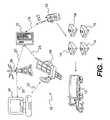
- FIG. 1is a an overview of the tracking system according to the present invention
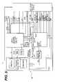
- FIG. 2is a block diagram illustrating three components of the tracking system of the invention illustrated in FIG. 1 ;
- FIG. 3is a block diagram of one embodiment of a GPS receiver contemplated for incorporation into the master unit that forms a part of the tracking system of the invention
- FIG. 4is a block diagram of one embodiment of a WiFi module contemplated for incorporation into the master unit that forms a part of the tracking system of the invention
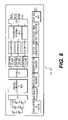
- FIG. 5is a block diagram of one embodiment of a GPRS modem contemplated for incorporation into the master unit that forms a part of the tracking system of the invention
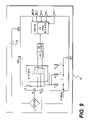
- FIG. 6is a block diagram of one embodiment of a radio contemplated for incorporation into the master unit and the tag that form parts of the tracking system of the invention
- FIG. 7is a block diagram of one embodiment of a signal microcontroller contemplated for incorporation into the master unit and the tag that form parts of the tracking system of the invention
- FIG. 8is a block diagram of one embodiment of an accelerometer contemplated for incorporation into the master unit and the tag that form parts of the tracking system of the invention
- FIG. 9is a block diagram of one embodiment of an altimeter contemplated for incorporation into the master unit that forms a part of the tracking system of the invention.
- FIG. 10is a block diagram of one embodiment of a temperature sensor contemplated for incorporation into the master unit and the tag that form a part of the tracking system of the invention
- FIG. 11is a block diagram of one embodiment of a shock sensor contemplated for incorporation into the tag that forms a part of the tracking system of the invention.
- FIG. 12is a block diagram illustrating the design of the master unit illustrated in FIG. 2 ;
- FIG. 13is a block diagram illustrating an alternative contemplated embodiment of the master unit that forms a part of the tracking system of the invention
- FIG. 14is a block diagram illustrating another variation of the master unit that forms a part of the tracking system of the invention.
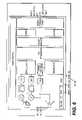
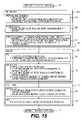
- FIG. 15is a flow chart illustrating one contemplated method associated with operation of the tracking system of the invention.
- FIG. 16is a first part of a flow chart illustrating another method contemplated for use in association, with the tracking system of the invention.
- FIG. 17is the second part of a flow chart illustrating another method contemplated for use in association, with the tracking system of the invention.
- the tracking system 10 of the inventionis broadly illustrated in FIG. 1 .
- the tracking systemincludes a transportation vehicle 12 .
- the transportation vehicle 12may include a truck (as shown), a railway car, an ocean-going ship, an airplane, or any other suitable alternative. While a truck is illustrated in FIG. 1 , the invention is not meant to be limited solely to transportation of parcels via highways. As will be made apparent from the discussion herein, international shipping is intended to fall within the scope of the invention. Accordingly, cargo ships and airplanes also are intended to fall within the scope of the term “transportation vehicle” 12 . Other transportation vehicles are intended to fall within the scope of this term, although these other transportation vehicles are not specifically enumerated herein.
- the transportation vehicle 12is expected to contain one or more parcels 14 .
- this termis intended to broadly encompass any item selected for shipment from a start location to a final location. These items may include, but are not limited to letters, packages, boxes, crates, parcels, shipping containers, pallets, equipment, etc.
- the term “parcel”is intended to encompass any item that is shipped from a point of origin to a destination. While it is expected in most instances that more than one parcel 14 will be placed within one transportation vehicle 12 , it is possible that only one parcel 14 may be placed into one transportation vehicle 12 , especially in cases where the parcel is a large object. For example, if an industrial bulldozer was to be shipped, it may constitute the only parcel 14 in or on the shipping vehicle 12 .
- a tag 16is associated with the group of parcels 14 .
- One tag 16may be affixed to each of the parcels individually or the tag 16 may be associated with a plurality of parcels 14 .
- the tag 16is a receiver and transmitter of electromagnetic signals, including radio signals.
- the tag 16may be a transmitter only, as may be appropriate for a given shipping environment.
- the tag 16transmits and/or receives signals, via a one-way or a two-way communication link 18 to a master unit (“MU”) 20 .
- the master unit 20transmits and receives signals via one or more communication links 22 , 24 to at least one of a tower 26 and/or a satellite 28 .
- the tower 26 and/or the satellite 28transmit and receive signals via communication links 30 , 32 to a central processor 34 . Details concerning each of these components are provided in greater detail below. However, as an overview, the following generalizations are presented.
- the tag 16transmits at least one from several possible signals concerning the parcel or parcels 14 with which the tag 16 is associated.
- the tag 16may transmit identifying information about the parcels 14 .
- the identifying informationmay include content information, point of origin, destination information, and name and contact information for the shipper and the recipient, for example.
- the identifying informationalso may encompass a broad range of additional invoice information that may be applicable for inspection by customs officials.
- Other identifying informationalso may be included, and the invention is not intended to be limited to the small number of examples provided herein.
- the tag 16also may include various sensors. For example, the tag 16 may detect specific shipping-related parameters including, but not limited to, humidity, temperature, acceleration rate(s), shocks, and/or other types of information germane to a particular shipping environment. These shipping parameters are broadly referred to as “shipping information” herein. Once detected, the shipping information may be stored by the tag 16 and transmitted to the master unit 20 on a continuous or an intermitted basis. It is contemplated that, to conserve battery power, the shipping information will be transmitted by the tag 16 on an intermittent basis, e.g., every 5 minutes, 10 minutes, 15 minutes, half hour, hour, etc. The tag 16 is contemplated to act as a mini-“flight recorder” during transit of the parcel from the point of origin to the destination.
- shipment informationmay be stored by the tag 16 and transmitted to the master unit 20 on a continuous or an intermitted basis. It is contemplated that, to conserve battery power, the shipping information will be transmitted by the tag 16 on an intermittent basis, e.g., every 5 minutes, 10
- the tag 16is contemplated to provide a continuous record of the parcel's journey from start to finish. While the tag 16 will include nonvolatile memory, that memory may not be sufficiently large to save all of the shipping information generated for the parcels 14 . As such, the tag 16 is expected to transmit its shipping information to the master unit 20 to clear memory space for additional information during transit. Of course, if the shipment distance is short (and the time associated with the shipment is short), the tag 16 may have sufficient memory space to retain all of the shipping information generated for the parcels 14 .
- the master unit 20is contemplated to be local to a group of the tags 16 .
- one master unit 20may be positioned in the transportation vehicle 12 .
- the master unit 20will then receive transmissions from each of the tags 16 located within the transportation vehicle 12 and transmit shipping information to the central processor 34 .
- the master unit 20may be in continuous communication with the central processor 34 or may be in intermittent contact therewith.
- intermittent contactwill be relied upon to conserve power consumed by the master unit 20 .
- the master unit 20is less likely to be constrained by power limitations because of its placement on the transportation vehicle 12 .
- the transportation vehicle 12may supply power to the master unit 20 on a continuous or an intermittent basis to assure proper functioning of the master unit 20 .
- the battery capacity of the master unit 20will be sufficient for recording shipping information for several days, thereby capturing shipping information for long duration shipping instances.
- the master unit 20is contemplated to be the repository for information generated by the individual tags 16 . In this context, therefore, the master unit 20 is contemplated to act as the “flight recorder” for the plurality of parcels with which it is associated. The master unit 20 will, therefore, receive and store a complete history of the transit conditions for each of the parcels 14 within its monitoring purview.
- the master unit 20may be associated with a group of parcels 14 without being positioned within the transportation vehicle 12 .
- the master unit 20may be associated with a pallet of parcels 14 that are placed within the transportation vehicle 12 .
- the master unit 20will operate in the same fashion as discussed above.
- the tower 26which receives shipping information from and sends signals to the master unit 16 , may be any type of electromagnetic signal receiver/transmitter.
- the tower 26is a terrestrial radio tower or equivalent.
- the tower 26is a terrestrial microwave tower or equivalent.
- the type of signal transmissionmay be analog or digital, as should be appreciated by those skilled in the art.
- the actual type of electromagnetic signals being usedis not important to the operation of the invention. To the contrary, the invention is intended to encompass any type of electromagnetic signals.
- the satellite 28is contemplated to one in Earth orbit. Like the tower 26 , the satellite 28 may receive and transmit any type of electromagnetic signals.
- the central processor 34is contemplated to be positioned at a location where coordination of shipping occurs. Of course, as should be appreciated by those skilled in the art, the central processor 34 may be physically positioned in any suitable location without departing from the scope of the invention.
- the central processor 34may be a personal computer, a main frame computer, a personal data assistant, or any other alternative or variation thereof. As may be appreciated by those skilled in the art, the central processor 34 need not be of any particular type. In addition, it is noted that the central processor 34 need not be a single processor but may include a plurality of processors networked together, via wired or wireless communication links.
- any suitable linkmay be employed without departing from the scope of the invention.
- the different types of linksmay include, but are not limited to, wired or wireless links, radio links, electromagnetic links, cellular network links, global positioning system (“GPS”) links, Bluetooth links, personal area network (“PAN”) links, WiFi links, local area network links, or any variation(s) thereon. It is contemplated that the tracking system 10 of the invention will operate in the general manner discussed below. Of course, there are an unlimited number of variations that may be employed without departing from the scope of the invention.
- this link 18is expected to be of a geographically-limited nature.
- the tags 16are not expected to exceed a distance of 100 feet or so from the master unit 20 . Accordingly, the tags 16 do not need exceptionally strong transmitters and/or receivers to communicate with the master unit 20 .
- the tags 16may communicate with the master unit 20 via a suitable local transmission like a WiFi network (“WiFi” is a term used for wireless technology based on IEEE 802.11 standards, which encompass wireless local area networks (“WLANs”)), a generic wireless local area network (“WLAN”), a local area network (“LAN”), and/or a Bluetooth connection (or a suitable equivalent).
- WiFiis a term used for wireless technology based on IEEE 802.11 standards, which encompass wireless local area networks (“WLANs”)
- WLANwireless local area network
- LANlocal area network
- Bluetooth connectionor a suitable equivalent
- Bluetoothis a term understood in the art and is intended to be generic to wireless personal area networks (“PANs”) and their equivalents. Signals to and from master units 20 via the communication links 22 , 24 , on the other hand, are required to traverse much larger distances. As a result, these signals are contemplated to occur over communication lines including cellular networks and satellite networks, or the like. Signals passing from the tower 26 and/or the satellite 28 are contemplated to be made across similar transmission channels.
- the master unit 20may include some of the functionality described above with respect to the tags 16 , at least in certain configurations.
- the master unit 20may include one or more sensors to detect parameters such as humidity, temperature, acceleration, shock, etc.
- the tags 16need not include sensors to detect one or more of the shipping parameters.
- both the master unit 20 and the tags 16may include sensors to detect shipping parameters associated with the parcels 14 . In such an arrangement, both the master unit 20 and the tags 16 will collect information concerning the shipping parameters, providing redundancy and, therefore, greater reliability in the data.
- the tracking system 10 of the inventionwill be employed on a global scale, it is possible that the tracking system 10 may be employed only on a local scale.
- the tracking system 10may be employed at a warehouse. In such a case, only tags 16 and master units 20 may be employed without the need for one or more towers 26 and/or satellites 28 .
- FIG. 2provides a high-level electrical schematic for the tracking system 10 of the invention. This electrical schematic illustrates features of the master unit 20 , an external processor 78 , and one tag 16 .
- the unitincludes a battery compartment 36 . While FIG. 2 indicates that the battery compartment may contain 2 “AA”-style batteries, the invention is intended to encompass any other suitable battery arrangements, whether disposable or rechargeable.
- the battery(ies)supply power to the signal microcontroller 38 and other components.
- the microcontroller/processor 38is connected to debug indicator 40 .
- the debug indicator 40may include a small display screen or one or more light emitting diodes (“LEDs”) that provide an indication of the status of the tag 16 .
- the debug indicator 40may include several LEDs to display the level of the battery charge.
- a display or one or more LEDsmay be employed to indicate a malfunction or other error.
- Other indicationsalso may be provided for, as should be appreciated by those skilled in the art.
- the microcontroller 38also is connected to a radio 42 , which prepares the data from the processor 38 for transmission to the master unit 20 .
- the radio 42is connected to an antenna 44 .
- the antenna 44may be internal to the tag 16 or may be external, as should be appreciated by those skilled in the art.
- the radio 42 and antenna 44generate signals at a 2.4 GHz frequency. While this particular frequency is contemplated for the invention, those skilled in the art should appreciate that any other frequency may be employed without departing from the scope of the invention.
- the sensorsmay include a humidity sensor 46 , an accelerometer 48 , and a temperature sensor 50 , among others.
- the temperature sensor 50is illustrated as a part of the processor 38 . However, as should be appreciated by those skilled in the art, this arrangement is not required.
- the temperature sensor 50may be included as a part of the sensor suite 52 .
- the sensor suite 52also includes three additional items, a peak hold circuit 54 , a shock sensor 56 (also referred to as a peak detector), and an Electrically Erasable Programmable Read-Only Memory (“EEPROM”) 58 , which is a non-volitile, storage chip used in computers and other devices to store small amounts of volatile data, e.g., calibration tables or device configurations.
- EEPROMElectrically Erasable Programmable Read-Only Memory
- other suitable memory typesmay be used including, but not limited to a flash memory.
- the shock sensor 56is provided to detect unfavorable impacts experienced by the tag 16 . With respect to the peak hold circuit 54 , this circuit is intended to retain the peak read by the shock sensor 56 until the microcontroller 38 reads that information.
- the master unit 20includes a battery charge circuit 60 .
- the battery charge circuit 60is connectable to an external power supply 62 .
- the external power supply 62may be connected to the battery charge circuit 60 to charge the battery 64 .
- the master unit 20may be powered by disposable batteries, as may be required by the tracking system 10 . Since the master unit 20 is intended to operate independently of a continuous power source, the power supply 62 is intended to be separable from the master unit 20 .
- the batteryprovides power to any of a number of electronic components in the master unit 20 including, among them, a power distributor 66 .
- the power distributor 66may be connected to a input/output circuit 68 .
- the input/output circuit 68may include a number of input connectors including a power input port 70 for the external power supply 62 .
- the input/output circuitalso may include a manual power switch 72 to provide manual control over the master unit 20 .
- the input/output circuit 68also includes a universal serial bus (“USB”) port 74 . As may be appreciated by those skilled in the art, more than one USB port 74 may be provided depending on the requirements of the tracking system 10 .
- a power indicator 76may include a display or a series of LEDs that indicate the current status of the power level of the battery (or batteries) 64 in the master unit 20 .
- the USB port 74may be provided to interface with an external processor 78 .
- the external processor 78may be a personal computer, a personal data assistant (“PDA”) or other suitable alternative, whether portable or not.
- the external processor 78includes two USB ports 80 , 82 .
- the USB port 80is connected to the USB port 74 to permit the external processor 78 to communicate directly with the master unit 20 via a wired communication link 84 .
- This communication link 84may be used to supply data to the master unit 20 or retrieve data from the master unit 20 , as necessary.
- the communication link 84may be used to program the master unit 20 with information specific to a particular shipment.
- the external processor 78also includes components to communicate wirelessly with the central processor 34 , the master unit 20 , or other devices including the tags 16 .
- the external processormay include a USB port 86 into which a radio dongle 88 is inserted.
- the radio dongle 88includes an antenna 90 for wireless communication.
- the external processor 78also includes a WiFi port 92 to which a WiFi antenna 94 is connected.
- the WiFi antenna 94 and the radio antenna 90may be incorporated alternatively into the external processor 78 without departing from the scope of the invention.
- the external processor 78also may include a barcode scanner. If included, the barcode scanner may read one or more barcodes on the parcels 14 in conjunction with communicating with the master unit 20 . In addition, the external processor 78 may be configured to communicate with one or more of the tags 16 .
- the master unit 20also includes a single board computer (“SBC”) 94 , which controls and coordinates the operation of the master unit 20 . While an SBC may be employed for the master unit 20 , other variations and equivalents may be employed without departing from the scope of the invention. Several components may be associated with the SBC 94 . In connection with FIGS. 12-14 , three contemplated arrangements for the master unit 20 are discussed. The arrangement illustrated in FIG. 2 is but one of the contemplated variations for the master unit 20 .
- SBCsingle board computer
- the master unit 20may include one or more sensors to detect shipping parameters and generate data associated therewith.
- the master unit 20includes a temperature sensor 96 , an altimeter 98 , and an accelerometer 100 . These may be the same types of sensors included in the tags 16 or they may differ from the sensors included in the tags 16 . Data generated by the sensors is stored for transmission by the master unit 20 .
- an altimetermay be included only in those master units 20 that are adapted for use on aircraft. If the master unit 20 is to be used only for parcels 14 being shipped via ground transportation, an altimeter 98 may be excluded without departing from the scope of the invention. It is noted that an altimeter 98 may not be used when the parcels 14 are placed in a pressurized cargo hold of an aircraft, as should be appreciated by those skilled in the art.
- the master unit 20 in FIG. 2also includes a GPS receiver 102 connected to an antenna 104 . Accordingly, GPS information may be received and stored by the master unit 20 . As should be appreciated by those skilled in the art, the GPS receiver 102 only receives GPS data. Information wirelessly transmitted by the master unit 20 may be routed via one of several different routes within the master unit 20 .
- the master unit 20includes a general packet radio service (“GPRS”) modem 106 , connected to an antenna 108 , and a satellite communication modem 110 connected to an antenna 112 .
- a switch 114is provided so that the SBC may select between the GPRS modem 106 and the satellite communication modem 110 depending on the communication link required for a particular shipping environment.
- the master unit 20When the master unit 20 is located within a cellular network, for example, the master unit 20 will access the GPRS modem 106 . When the master unit 20 is outside of a cellular network, the master unit 20 will access the satellite communication modem 110 . Alternatively, the master unit 20 will access either one of the modems 106 , 110 if communication strength with one of the communication networks is stronger than the other.
- a GPRS modem 106is but one of several different modems that may be selected for use with the invention. Other systems relying on CDMA, TDMA, UMTS, EDGE, 3G, and 4G formats, etc., may also be employed without departing from the scope of the invention. Moreover, the GPRS modem 106 may incorporate functionality to interface with the local cellular network regardless of the data transmission format.
- the master unit 20includes a WiFi module 114 , a radio 116 , a mixed signal controller 118 , an antenna switch 120 , and an antenna 122 .
- the WiFi module 114permits communication with a local WiFi network as opposed to a GPRS network or a satellite communications network.
- the radio 116 and the mixed signal controller 118permit communication between the master unit 20 and one or more of the tags 16 . It is noted that the radio 116 and the mixed signal controller 118 are the same as the radio 42 and the mixed signal controller 38 in the tag 16 that is illustrated in FIG. 2 . Of course, the components need not be the same to practice the invention.
- the switch 120permits access to the antenna 122 by either the WiFi module 114 or the radio 116 , as may be required for operation of the master unit 20 .
- Antennas 108 , 112 , and 122are provided in the master unit 20 to communicate with the central processor 34 via one or more communication protocols 124 .
- FIG. 3is a block diagram of the GPS receiver 102 that is illustrated in FIG. 2 .
- the GPS receiver 102 that is illustratedis commercially available from u-blox (u-blox America, Inc., 1902 Campus Commons Drive, Suite 310, Reston, Va. 20191, USA) under the identifying number LEA-4H. It should be noted that this particular GPS receiver 102 is not required to practice the invention. This is but one possible embodiment contemplated for use with the invention. Since the circuitry of the GPS receiver 102 is not important to the tracking system 10 of the invention, a discussion is not presented here. With respect to the GPS receiver 102 , it is contemplated that the GPS receiver 102 will be sensitive enough to pick up even a weak GPS signal (i.e., ⁇ 155 dBm), thereby assuring capture of location information even in remote locations.
- a weak GPS signali.e., ⁇ 155 dBm
- FIG. 4is a block diagram for the WiFi module 114 .
- the illustrated WiFi module 114is commercially available from DPAC (Quatech, Inc., A DPAC Technologies Company, 5675 Hudson Industrial Parkway, Hudson, Ohio 44236, USA) under the identifying number WLNB-AN-DP102. It should be noted that this particular WiFi module 114 is not required to practice the invention as any alternative may be employed without departing from the scope of the invention. The illustration of this particular model for the WiFi module 114 is intended to be exemplary only. Since the circuitry of the WiFi module 114 is not important to the operation of the invention, it is not discussed herein.
- the master unit 20will communicate with a wireless LAN when the master unit 20 is within range of the wireless LAN. Since the invention is intended for international use, the WiFi module 114 should be selected to comply with international standards. Of course, master units 20 for local shipping environments (i.e., the United States only) are also contemplated and are intended to fall within the scope of the invention.
- the satellite communication module 110may be selected from any one of a number of different, commercially-available products.
- the master unit 10may incorporate the 9601 SBD model available from Iridium Satellite LLC, 6707 Economics Boulevard, Suite 300, Bethesda, Md. 20817, USA. Of course, this particular model is not required to practice the invention, as should be apparent to those skilled in the art.
- the master unit 20will communicate via the satellite communication module 110 when the master unit 20 is within range of a satellite network. As will be discussed in greater detail below, the master unit 20 will communicate with the satellite network when either the GPRS network or the wireless LAN is not available. For shipping purposes, the master unit 20 will not interface with any of the satellite network, the GPRS network, or the wireless LAN when the master unit 20 is placed on board an aircraft. At present, wireless communications on board aircraft are not permitted. Should these regulations change, however, the master unit 20 may remain active during flight.
- the tracking system 10 of the inventionmay be designed to access the flight beacon for the aircraft and to track the location of the aircraft, rather than the mater unit 20 .
- FIG. 5is a block diagram of the GPRS modem 106 shown in FIG. 2 .
- the block diagram provided in FIG. 5is specifically for a product made by Siemens (Siemens AG, Wittelsbacherplatz 2, D-80333 Kunststoff, Germany) under the product identifier TC63.
- SiemensSiemens AG, Wittelsbacherplatz 2, D-80333 Kunststoff, Germany
- this particular model for the GPRS modem 106is merely exemplary. It is not required to practice the invention and any of a number of other suitable alternatives may be employed without departing from the scope of the invention. As a result, the specific details of the circuitry provided in FIG. 5 are not discussed herein.
- the GPRS modem 106is intended to communicate via a GPRS cellular to wireless network at least with quadband capability. As noted above, the GPRS modem 106 may include functionality to interface with other networks. Moreover, equivalents to the GPRS modem 106 may be used without departing from the scope of the invention.
- FIG. 6is a block diagram of the radio module 42 , 116 .
- This particular block diagrampresents a circuit overview for a radio available from Texas Instruments (Texas Instruments, 12500 TI Boulevard, Dallas, Tex. 75243, USA) under the product code CC2500.
- This particular model of radiois not required to practice the invention but is merely presented as one contemplated embodiment for the invention. Since the details of the circuitry are not required to practice the invention, details are not discussed herein. As should be apparent to those skilled in the art, any other radio may be employed without departing from the scope of the invention.
- the radio module 42 , 116 in the illustrated embodimentis a 2.4 GHz radio that permits communication between the master unit 20 and the tags 16 .
- the radio module 42 , 116will operate one four separate frequencies so that if a link is lost between one of the tags 16 and the master unit 20 , the wireless link may be reestablished via another of the frequencies available to the tag 16 and the master unit 20 .
- the master unit 20 and the tag 16are contemplated to include functionality so that if communication between a master unit 20 and a tag 16 is lost, the master unit 20 will generate an alarm.
- This functionmay be used to generate a “geofence” in association with the master unit 20 .
- the master unit 20will keep track of the tags 16 that are within the transmission distance of the radio module 116 . If a tag 16 is removed from the transmission area associated with the master unit 20 , the master unit 20 will trigger an alarm.
- the master unit 20is used to prevent parcels 14 from being moved to an incorrect transportation vehicle 12 , for example.
- the master unit 20also may prevent theft of parcels 14 , as may be appreciated by those skilled in the art.
- FIG. 7is a block diagram of the radio microcontroller 38 , 118 illustrated in FIG. 2 .
- This particular radio microcontroller 38 , 118is commercially available from Texas Instruments under the product identifier MSP430F2232, as indicated in the drawing.
- This particular microcontrolleris not required to practice the invention but is presented merely as one contemplated embodiment. As such, the specifics of the circuitry are note discussed herein. Moreover, as should be clear, other microcontrollers may be employed without departing from the scope of the invention.
- the microcontroller 118provides an interface between the SBC 94 and the radio module 116 in the master unit 20 .
- the microcontroller 38also provides an interface with the radio module 42 in the tag 16 .
- the microcontroller 38 , 118provides an algorithm to control the 2.4 GHz radio module 42 , 116 so that the master unit 20 and the tag 16 may communicate periodically with one another.
- FIG. 8is a block diagram of an accelerometer 48 , 100 contemplated for use with the master unit 20 and the tag 16 .
- FIG. 8is a block diagram of an accelerometer available from VTI Technologies (VTI Technologies Oy, Myllynkivenkuja 6, 01620 Vantaa, Finland) under the product code SCA3000-D01. This particular accelerometer is detailed to illustrate one contemplated embodiment of the invention and is, therefore, not meant to be limiting of the invention. Since the illustrated accelerometer 48 , 100 is exemplary only, a detailed discussion of the circuit diagram is omitted. Those skilled in the art should readily recognize that any of a number of different accelerometers may be employed without departing from the scope of the invention.
- the accelerometer 48 , 100is contemplated to detect acceleration of the master unit 20 and the tag 16 . Acceleration measurements may be made during takeoff and landing of an aircraft, for example.
- the accelerometer 48 , 100may detect acceleration in three dimensions.
- the accelerometer 48 , 100is expected to interface with the master unit 20 .
- the master unit 20Upon detecting a takeoff, the master unit 20 will cease transmission functions until a landing deceleration is detected. Once the landing deceleration is detected, the master unit 20 will resume it normal function. In connection with this function, the master unit 20 will disable and enable transmissions to and from the tags 16 during flight. In this way, the master unit 20 and the tags 16 will not transmit signals while in flight, thereby complying with applicable flight regulations.
- FIG. 9is a block diagram of one altimeter 98 contemplated for use with the master unit 20 .
- the altimeter 98 diagrammedis commercially from Hope Microelectronics (a.k.a., HopeRF Microelectronics) (Hope Microelectronics Co., Ltd, also doing business as Shenzhen Huiyee Hope Electronics Co., Ltd, Rm. T2-8B, Emperor Regency Bldg., 6012 ShenNan Rd., Futian, ShenZhen, GuangDong 518034, China).
- the altimeter 98 shownis merely exemplary of one commercially-available altimeter 98 that is contemplated for incorporation into the master unit 20 of the invention.
- altimeter 98Since the exact details of the altimeter 98 are not required to practice the invention, an exhaustive description of the altimeter 98 is not provided herein. As should be apparent to those skilled in the art, any suitable alternative altimeter 98 may be employed without departing from the scope of the invention.
- FIG. 10presents one contemplated embodiment for the temperature sensor 50 , 96 incorporated into the tag 16 or the master unit 20 .
- the circuit diagram providedis for a temperature sensor 50 , 96 that is commercially available from National Semiconductor Corporation (2900 Semiconductor Dr., P.O. Box 58090, Santa Clara, Calif. 95052-8090, USA) under the product descriptor code LM92. Since the exact details of the temperature sensor 50 , 96 are unimportant to the operation of the tag 16 or the master unit 20 , further discussion of the diagram is not made herein. As should be apparent to those skilled in the art, any other temperature sensor 50 , 96 may be employed without departing from the scope of the invention.
- FIG. 11is a block diagram of a shock sensor 56 contemplated for use with the tag 16 .
- the shock sensor 56is commercially available from Freescale Semiconductor, Inc. (Freescale Semiconductor, Inc., 6501 W William Cannon Dr, Austin, Tex. 78735-8523, USA) under the product code MMA7261QT.
- This particular shock sensoris not required to practice the present invention. Accordingly, a detailed discussion of the specifics of the components is not included in this discussion. As noted with respect to others of the components provided as examples, this particular shock sensor 56 is not required to practice the present invention.
- the shock sensor 56detects shocks experienced during transit, thereby permitting evaluation if the parcels 14 have been dropped, for example, during transit.
- FIGS. 12-14provide three alternative approaches to the design of the master controller.
- FIG. 12illustrates a master controller based on an SBC. This is the same design provided in FIG. 2 .
- FIG. 13illustrates a microcontroller approach to the design of the master unit.
- FIG. 14offers a computer on module approach to the master unit.
- FIG. 12is a block diagram outlining the design of the master unit 20 , which is illustrated in great detail in FIG. 2 .
- the master unit 20is based on an SBC approach, as discussed above.
- the SBCincludes two parts: (1) a processor board, which contains all of the functionality of the serial interfaces (i.e., UART, SBI, USB, etc.), and (2) a carrier board, which brings connectors to the periphery of the processor board.
- These connectorsinclude, but are not limited to, USB, VGA, Ethernet, PS/2, and others.
- FIG. 13is a block diagram outlining the design of a master unit 130 using a microcontroller-based architecture.
- a printed circuit boardcontains all of the peripheral modules and a host microcontroller 132 .
- the microcontrollermay be provided by Atmel (Atmel Corporation, 2325 Orchard Parkway, San Jose, Calif. 95131, USA) under the product descriptor AT91SAM9260. Of course, any other microcontroller may be employed without departing from the scope of the invention.
- the microcontroller 132communicates with the sensors and the communication modules and includes memory for data storage. Flash and SDRAM memories may be provided, as would be appreciated by those skilled in the art.
- FIG. 14is a block diagram that illustrates the third contemplated embodiment for the master unit 134 .
- This embodimentis based on a Computer-on-Module (“CoM”) architecture.
- the master unit 134includes a board connector 136 and a CoM board 138 .
- cabling between the CoM and the peripheralsmay be largely eliminated, unlike in the master unit 20 based on the SBC.
- FIG. 15provides a high-level flow chart outlining one contemplated method associated with the operation of the tracking system 10 of the invention.
- the tracking method 136begins at 138 and includes three primary sections, a pre-transit portion 140 , a transit portion 142 , and a post-transit portion 144 .
- the methodends at 146 .
- the pre-transit portion 140 of the tracking method 136includes three sub-portions: (1) the master units 20 are prepared at 148 , (2) the tags 16 are prepared at 150 , and (3) the tags 16 are checked at 152 .
- the master units 20are prepared in the pre-transit portion 140 by charging the batteries 64 and downloading configuration parameters and IDs for the associated tags 16 via the external processor 78 .
- the configuration parametersit is noted that the master unit 20 may be configured for each shipment. For example, some shipments may include collection of humidity information while others do not. As a result, the master units 20 for each of these shipments may be configured differently for each of the shipments. In the alternative, both shipments may be configured in the same manner. At the conclusion of the shipment where humidity information is not required, the information may be deleted altogether.
- the tags 16are prepared for shipment. To prepare the tags 16 , batteries are installed in the battery compartment 36 to assure that the tags 16 have a sufficiently large charge to operate for the entire duration of the shipment. Once the batteries are installed, the tags 16 may initiate communication with the master unit 20 . Since the configuration parameters have been loaded into the master unit 20 at 148 , relevant instructions may be forwarded to the tags 16 from the master unit 20 .
- tag communicationsare checked and a pre-transit report is generated. Once the tags 16 become active, the master unit 20 will communicate with each of the tags to assure that a communication link 18 may be established between them. If all of the communication links 18 are successful, then the master unit 20 and the tags 16 may proceed to the transit portion 142 of the method 136 .
- the transit portion 142 of the method 136includes two sub-parts: (1) a tag operational portion 154 , and (2) a master unit operational portion 156 .
- the tag operational portion 154involves two operations. First, the tag 16 collects and stores sensor data. Second, the tag uploads information to the master unit 20 upon receiving a request from the master unit 20 to do so. After uploading information to the master unit 20 , the tag 16 will clear its internal memory so that there is sufficient space for additional data.
- the master unit operational portion 156includes four operations. First, the master unit 20 checks for GPS data when the master unit 20 is not on board an aircraft.
- the master unit 20will have already provided notice to the central processor 34 or the tracking server so that the tracking system 10 will track the aircraft beacon rather than searching for signals from the master unit 20 .
- the master unit 20will initiate periodic requests for shipping information from the associated tags 16 .
- the tags 16provide the shipping information in response to such a request. This request is made if the master unit 20 and the tags 16 are not on board an aircraft. If the master unit 20 and the tags 16 are on board an aircraft, this function is disabled until after the aircraft lands.
- the master unit 20will initiate periodic contact with the central processor 34 or the tracking server if the master unit 20 is not on board an aircraft.
- the master unit 20will disable this function until after the aircraft lands. Fourth, in connection with initiating contact with the central processor 34 or tracking server, the master unit will upload shipping information from its memory to the central processor 34 , thereby clearing memory space for additional shipping information.
- the post-transit portion 144 of the method 136includes two sub-parts: (1) a master unit shut-down phase 158 , and (2) a tag shut-down phase 160 .
- the master unit shut-down phase 158the master unit 20 is recovered from the group of parcels 14 and is connected to the external processor 78 .
- the external processor 78may recover any additional information from the master unit 20 that was not previously transmitted to the central processor 34 .
- the external processor 78may provide instructions for the master unit 20 to cease operation.
- the external processor 78may execute a diagnostic program to analyze the current condition of the master unit 20 and provide a report. The report may indicate, for example, if the master unit 20 is functional and ready for a subsequent shipment.
- Concerning the tag shout-down phase 160the tag 16 is recovered from the parcels 14 and the batteries are removed so that the tag 16 ceases operation.
- FIG. 16provides a flow diagram for a method of operation of the invention.
- the method 162begins at 164 .
- the method 162includes tagging at least one item, such as a parcel 14 , with a tag 16 .
- a shipping parameteris measured by the tag 16 for the parcel 14 .
- the tag 16generates tag shipping data based upon the shipping parameter.
- the tag 16transmits the tag shipping data to the master unit 20 .
- the master unit 20receives the tag shipping data from the tag 16 .
- the master unit 20stores the tag shipping data in memory associated with the master unit 20 .
- Reference number 178indicates that the method 162 continued to FIG. 17 .
- the method 162continues at 180 , where the master unit 20 measures shipping information.
- the master unit 20then generates master unit shipping data that is also stored in the memory of the master unit together with the tag shipping data at 184 .
- the master unittransmits the shipping data to the central processor 34 , which step is identified at 186 .
- the central processor 34determines wither a location of the parcel 14 or a condition of the parcel 14 . This may be repeated at several points during the shipping journey.
- the master unit 20also receives GPS data via the GPS receiver 102 .
- the data from the GPS receiver 102becomes a part of the master unit shipping data that is transmitted to the central processor 34 .
- This datapermits the central processor to determine, in real time, the location of the parcels 14 .
- the central processor 34will calculate the location of the master unit 20 and the tags 16 (and associated parcels 14 ) based on one or more of the various inputs discussed above. While this functionality is contemplated to be dedicated to the central processor 34 , the master unit 16 also may include this functionality.
- the central processor 34is contemplated to be connected with the Internet. As a result, the central processor 34 may be accessed by a shipper and/or a recipient to track the location of the parcels 14 during shipment. Since the master unit 20 provides periodic shipping information during transit, the central processor 34 may provide this information to the shipper and/or the recipient. As a result, it is possible for the shipper and/or the recipient to locate one or more parcels 14 at any point during transit from the shipping origin to the destination.
Landscapes
- Engineering & Computer Science (AREA)
- Business, Economics & Management (AREA)
- Economics (AREA)
- Physics & Mathematics (AREA)
- General Physics & Mathematics (AREA)
- Theoretical Computer Science (AREA)
- Entrepreneurship & Innovation (AREA)
- Strategic Management (AREA)
- Development Economics (AREA)
- Microelectronics & Electronic Packaging (AREA)
- Computer Hardware Design (AREA)
- Human Resources & Organizations (AREA)
- Marketing (AREA)
- Operations Research (AREA)
- Quality & Reliability (AREA)
- General Business, Economics & Management (AREA)
- Tourism & Hospitality (AREA)
- Computer Networks & Wireless Communication (AREA)
- Accounting & Taxation (AREA)
- Finance (AREA)
- General Engineering & Computer Science (AREA)
- Management, Administration, Business Operations System, And Electronic Commerce (AREA)
- Position Fixing By Use Of Radio Waves (AREA)
Abstract
Description
Claims (41)
Priority Applications (6)
| Application Number | Priority Date | Filing Date | Title |
|---|---|---|---|
| US11/969,667US7895131B2 (en) | 2008-01-04 | 2008-01-04 | Cargo tracking apparatus, system and method |
| CA2710916ACA2710916A1 (en) | 2008-01-04 | 2008-09-17 | Cargo tracking apparatus, system, and method |
| BRPI0822231-2ABRPI0822231A2 (en) | 2008-01-04 | 2008-09-17 | Cargo tracking apparatus, system and method. |
| EP08870309AEP2243040A4 (en) | 2008-01-04 | 2008-09-17 | Cargo tracking apparatus, system, and method |
| PCT/US2008/076676WO2009088538A1 (en) | 2008-01-04 | 2008-09-17 | Cargo tracking apparatus, system, and method |
| US13/017,413US8392339B2 (en) | 2008-01-04 | 2011-01-31 | Cargo tracking apparatus, system and method |
Applications Claiming Priority (1)
| Application Number | Priority Date | Filing Date | Title |
|---|---|---|---|
| US11/969,667US7895131B2 (en) | 2008-01-04 | 2008-01-04 | Cargo tracking apparatus, system and method |
Related Child Applications (1)
| Application Number | Title | Priority Date | Filing Date |
|---|---|---|---|
| US13/017,413ContinuationUS8392339B2 (en) | 2008-01-04 | 2011-01-31 | Cargo tracking apparatus, system and method |
Publications (2)
| Publication Number | Publication Date |
|---|---|
| US20100076902A1 US20100076902A1 (en) | 2010-03-25 |
| US7895131B2true US7895131B2 (en) | 2011-02-22 |
Family
ID=40853355
Family Applications (2)
| Application Number | Title | Priority Date | Filing Date |
|---|---|---|---|
| US11/969,667Active - Reinstated2029-04-18US7895131B2 (en) | 2008-01-04 | 2008-01-04 | Cargo tracking apparatus, system and method |
| US13/017,413Active - Reinstated2028-01-19US8392339B2 (en) | 2008-01-04 | 2011-01-31 | Cargo tracking apparatus, system and method |
Family Applications After (1)
| Application Number | Title | Priority Date | Filing Date |
|---|---|---|---|
| US13/017,413Active - Reinstated2028-01-19US8392339B2 (en) | 2008-01-04 | 2011-01-31 | Cargo tracking apparatus, system and method |
Country Status (5)
| Country | Link |
|---|---|
| US (2) | US7895131B2 (en) |
| EP (1) | EP2243040A4 (en) |
| BR (1) | BRPI0822231A2 (en) |
| CA (1) | CA2710916A1 (en) |
| WO (1) | WO2009088538A1 (en) |
Cited By (21)
| Publication number | Priority date | Publication date | Assignee | Title |
|---|---|---|---|---|
| US20110125663A1 (en)* | 2008-01-04 | 2011-05-26 | Tracking Innovations, Inc. | Cargo tracking apparatus, system and method |
| US20130265155A1 (en)* | 2012-04-10 | 2013-10-10 | Geoforce, Inc. | Location tracking with integrated identification of cargo carrier contents and related system and method |
| US8967469B2 (en)* | 2013-02-25 | 2015-03-03 | Ideal Innovations Incorporated | System and method for tracking items by means of longwave, magnetic signal tagging |
| US20150145650A1 (en)* | 2013-11-27 | 2015-05-28 | Michael Adam Levan | Method, software application, and system for tracking packages by global positioning system (gps) |
| US9049641B2 (en) | 2012-04-10 | 2015-06-02 | Geoforce, Inc. | Apparatus and method for radio frequency silencing in oil and gas operations, excavation sites, and other environments |
| US9082102B2 (en) | 2012-04-10 | 2015-07-14 | Geoforce, Inc. | System and method for remote equipment data management |
| US9225383B2 (en) | 2012-03-14 | 2015-12-29 | Geoforce, Inc. | System and method for implementation of a direct sequence spread spectrum transmitter |
| US9547079B2 (en) | 2014-02-06 | 2017-01-17 | Fedex Corporate Services, Inc. | Object tracking method and system |
| US9633326B2 (en) | 2015-06-10 | 2017-04-25 | Smart Catch Inc. | Load distribution and consolidation tracking system |
| US9658310B2 (en)* | 2015-06-16 | 2017-05-23 | United Parcel Service Of America, Inc. | Concepts for identifying an asset sort location |
| US10146214B2 (en) | 2012-07-05 | 2018-12-04 | Flextronics Ap, Llc | Method and system for collecting supply chain performance information |
| WO2019010450A1 (en) | 2017-07-07 | 2019-01-10 | Apptricity Corporation | Network edge controller and remote field service system |
| US10471478B2 (en) | 2017-04-28 | 2019-11-12 | United Parcel Service Of America, Inc. | Conveyor belt assembly for identifying an asset sort location and methods of utilizing the same |
| US10495723B2 (en) | 2015-06-16 | 2019-12-03 | United Parcel Service Of America, Inc. | Identifying an asset sort location |
| US10737827B2 (en) | 2018-11-07 | 2020-08-11 | International Business Machines Corporation | Tracking device enclosure |
| WO2021206744A1 (en) | 2020-04-07 | 2021-10-14 | Apptricity Corporation | Radio frequency (rf) location beacon with tunable antennas and cloud integration |
| WO2021206753A1 (en) | 2020-04-07 | 2021-10-14 | Apptricity Corporation | Flexible radio beacons and flexible delivery structures and system and method for using |
| US11209553B2 (en) | 2016-05-24 | 2021-12-28 | Flex Ltd. | Systems and methods for active supply chain monitoring |
| US11468755B2 (en) | 2018-06-01 | 2022-10-11 | Stress Engineering Services, Inc. | Systems and methods for monitoring, tracking and tracing logistics |
| US11773626B2 (en) | 2022-02-15 | 2023-10-03 | Stress Engineering Services, Inc. | Systems and methods for facilitating logistics |
| US12008840B2 (en) | 2011-03-07 | 2024-06-11 | Drivewyze Ltd. | Vehicle traffic and vehicle related transaction control system |
Families Citing this family (62)
| Publication number | Priority date | Publication date | Assignee | Title |
|---|---|---|---|---|
| TW200732980A (en)* | 2006-02-21 | 2007-09-01 | Guo Yuan Heng | Intelligent display control device, system and operation method for the same |
| US7974637B1 (en)* | 2007-09-24 | 2011-07-05 | Mikael Bror Taveniku | Passive mode tracking through existing and future wireless networks |
| US20100141445A1 (en)* | 2008-12-08 | 2010-06-10 | Savi Networks Inc. | Multi-Mode Commissioning/Decommissioning of Tags for Managing Assets |
| KR20120126059A (en)* | 2009-07-14 | 2012-11-20 | 엔보테크 네트워크 에스디엔 비에치디(657306-더블유) | Security seal |
| US8456302B2 (en)* | 2009-07-14 | 2013-06-04 | Savi Technology, Inc. | Wireless tracking and monitoring electronic seal |
| US8432274B2 (en) | 2009-07-31 | 2013-04-30 | Deal Magic, Inc. | Contextual based determination of accuracy of position fixes |
| EP2284563A1 (en)* | 2009-08-13 | 2011-02-16 | Deutsche Telekom AG | Method for detecting air plane flight events, mobile communication device, and computational unit therefor |
| CA2770755A1 (en)* | 2009-08-17 | 2011-02-24 | Deal Magic, Inc. | Contextually aware monitoring of assets |
| US8314704B2 (en) | 2009-08-28 | 2012-11-20 | Deal Magic, Inc. | Asset tracking using alternative sources of position fix data |
| US20110050397A1 (en)* | 2009-08-28 | 2011-03-03 | Cova Nicholas D | System for generating supply chain management statistics from asset tracking data |
| US8334773B2 (en) | 2009-08-28 | 2012-12-18 | Deal Magic, Inc. | Asset monitoring and tracking system |
| US20110054979A1 (en)* | 2009-08-31 | 2011-03-03 | Savi Networks Llc | Physical Event Management During Asset Tracking |
| US20110082812A1 (en)* | 2009-10-01 | 2011-04-07 | Abdul Hamid Salemizadeh | Package transport monitoring and analysis |
| US20110289013A1 (en)* | 2010-05-24 | 2011-11-24 | R&L Carriers, Inc. | Methods and Systems for Facilitating Movement of Articles of Freight |
| US20110291828A1 (en)* | 2010-06-01 | 2011-12-01 | Walker Timothy A | Embedded communication system for refrigerated transportation containers |
| US20110321055A1 (en)* | 2010-06-04 | 2011-12-29 | Enfora, Inc. | Transportation asset manager |
| US9357328B1 (en) | 2010-06-15 | 2016-05-31 | Thales Avionics, Inc. | Systems and methods for distributing content using attributes |
| DE102010033084A1 (en)* | 2010-08-02 | 2012-02-02 | Airbus Operations Gmbh | Freight evaluation for an aircraft |
| US8326359B2 (en)* | 2010-08-03 | 2012-12-04 | Honeywell International Inc. | Reconfigurable wireless modem adapter |
| US20120246091A1 (en)* | 2011-03-22 | 2012-09-27 | Deutsche Post Ag | Air shipment tracking process |
| EP2710530A4 (en)* | 2011-05-18 | 2015-01-28 | Axios Mobile Assets Corp | Systems and methods for tracking the usage of environmnetally efficient shipping equipment and for providing environmental credits based on such usage |
| US8626568B2 (en) | 2011-06-30 | 2014-01-07 | Xrs Corporation | Fleet vehicle management systems and methods |
| GB2494890B (en)* | 2011-09-21 | 2015-09-30 | Friendly Technologies Ltd | Inventorying transponders |
| EP2584505B1 (en)* | 2011-10-20 | 2017-08-02 | Deutsche Post AG | Comparison of position information |
| US20130162402A1 (en)* | 2011-12-27 | 2013-06-27 | Mathias Amann | Apparatus and Method for Providing Product Information |
| US20140379605A1 (en)* | 2012-01-30 | 2014-12-25 | Controlant Ehf. | Automatic supply-chain monitoring |
| US10783481B2 (en)* | 2012-03-22 | 2020-09-22 | Fedex Corporate Services, Inc. | Systems and methods for trip management |
| EP2856201A1 (en)* | 2012-06-01 | 2015-04-08 | Petari Usa, Inc. | Method and system for airplane container tracking |
| US9014943B2 (en) | 2012-08-10 | 2015-04-21 | Xrs Corporation | Transportation management techniques |
| FI123560B (en)* | 2012-08-16 | 2013-07-15 | Waertsilae Finland Oy | Integrated follow-up system and procedure |
| US9633576B2 (en) | 2012-12-13 | 2017-04-25 | Alliance Wireless Technologies, Inc. | Vehicle activity information system |
| US20140195455A1 (en)* | 2013-01-09 | 2014-07-10 | Position Logic Llc | Asset delivery visualization system and method |
| US20140365328A1 (en)* | 2013-06-06 | 2014-12-11 | VeriTread, LLC | Logistics-aware shipping estimation system and method |
| US20140365394A1 (en)* | 2013-06-06 | 2014-12-11 | VeriTread, LLC | Heavy equipment shipping estimation system and method |
| US20140365392A1 (en)* | 2013-06-06 | 2014-12-11 | VeriTread, LLC | Weighted-characteristics shipping estimation system and method |
| US20140365391A1 (en)* | 2013-06-06 | 2014-12-11 | VeriTread, LLC | Equipment-definable shipping estimation system and method |
| GB2518010A (en) | 2013-09-09 | 2015-03-11 | Crfs Ltd | Frequency discriminator |
| US8989053B1 (en) | 2013-11-29 | 2015-03-24 | Fedex Corporate Services, Inc. | Association management in a wireless node network |
| US10453023B2 (en) | 2014-05-28 | 2019-10-22 | Fedex Corporate Services, Inc. | Methods and node apparatus for adaptive node communication within a wireless node network |
| US11238397B2 (en) | 2015-02-09 | 2022-02-01 | Fedex Corporate Services, Inc. | Methods, apparatus, and systems for generating a corrective pickup notification for a shipped item using a mobile master node |
| MX388130B (en) | 2015-03-02 | 2025-03-19 | Locus Solutions Llc | SYSTEMS AND METHODS FOR MONITORING TRANSPORTED ITEMS. |
| US9674963B1 (en)* | 2015-06-03 | 2017-06-06 | Eric Sari | Multilevel machine to process coatings |
| US10057133B2 (en) | 2015-07-08 | 2018-08-21 | Fedex Corporate Services, Inc. | Systems, apparatus, and methods of enhanced monitoring for an event candidate associated with cycling power of an ID node within a wireless node network |
| EP3196837A1 (en)* | 2016-01-19 | 2017-07-26 | Danfoss A/S | A method for managing temperature data in a retail distribution chain |
| FR3049096B1 (en)* | 2016-03-16 | 2022-08-05 | Pa Cotte Sa | METHOD FOR MANAGING TRANSPORT OF AN OBJECT |
| FR3049099B1 (en)* | 2016-03-16 | 2018-03-30 | Pa.Cotte Sa | SYSTEM FOR DELIVERY OF OBJECTS BY INDIVIDUALS OF A COMMUNITY, IMPLEMENTING A SPATIO-TEMPORAL TRACEABILITY SYSTEM |
| EP3433809A4 (en) | 2016-03-23 | 2019-10-02 | Fedex Corporate Services, Inc. | SYSTEMS, APPARATUS AND METHODS FOR AUTOMATIC ADJUSTMENT OF BROADCAST ADJUSTMENT OF A NODE IN A WIRELESS NODE NETWORK |
| US20170372262A1 (en)* | 2016-06-28 | 2017-12-28 | Robert Ray Haney | System and Method for In-Transit Cargo Monitoring Utilizing Sensor Device and Telematics |
| CN109791210B (en)* | 2016-07-20 | 2023-07-21 | 统一包裹服务美国有限公司 | Location Tracking Using Beacons |
| FR3059452A1 (en)* | 2016-11-25 | 2018-06-01 | Universite De Montpellier | DEVICE COMPRISING RFID LABELS FOR FOLLOWING CONDITIONS FOR STORING AND / OR TRANSPORTING ARTICLES AND ASSOCIATED METHODS |
| US11037095B2 (en)* | 2017-09-11 | 2021-06-15 | Accenture Global Solutions Limited | Distributed ledger technology for freight system |
| US11558601B2 (en)* | 2017-11-06 | 2023-01-17 | Symbol Technologies, Llc | Methods and apparatus for initializing object dimensioning systems |
| JP6939463B2 (en)* | 2017-11-20 | 2021-09-22 | トヨタ自動車株式会社 | Server equipment and management system |
| US11418923B2 (en) | 2018-11-09 | 2022-08-16 | Amosense Co., Ltd | Asset tracking communication device |
| CA3121592A1 (en)* | 2018-12-03 | 2020-06-11 | Bayer Aktiengesellschaft | Tracking a collective of objects |
| US11170386B2 (en) | 2019-02-28 | 2021-11-09 | Accenture Global Solutions Limited | Environmental telemetry supply chain system |
| US11622234B2 (en) | 2019-09-13 | 2023-04-04 | Troverlo, Inc. | Passive asset tracking using observations of Wi-Fi access points |
| US11917488B2 (en) | 2019-09-13 | 2024-02-27 | Troverlo, Inc. | Passive asset tracking using observations of pseudo Wi-Fi access points |
| US11589187B2 (en) | 2019-09-13 | 2023-02-21 | Troverlo, Inc. | Passive sensor tracking using observations of Wi-Fi access points |
| CN112687066A (en)* | 2020-12-21 | 2021-04-20 | 山东产研信息与人工智能融合研究院有限公司 | Cotton bale anti-theft device and method for cotton warehouse |
| US20250252834A1 (en)* | 2023-09-27 | 2025-08-07 | Industrial Networks Llc | Dynamic communication methods for tag systems |
| US20250173631A1 (en)* | 2023-11-29 | 2025-05-29 | Honeywell International Inc. | Multi-entity adaptive trip activity and data security management system |
Citations (44)
| Publication number | Priority date | Publication date | Assignee | Title |
|---|---|---|---|---|
| US5815407A (en) | 1995-12-14 | 1998-09-29 | Motorola Inc. | Method and device for inhibiting the operation of an electronic device during take-off and landing of an aircraft |
| US6208910B1 (en) | 1999-04-23 | 2001-03-27 | Pitney Bowes Inc. | System and method for determining the location of a mail piece |
| US20020104013A1 (en) | 2001-02-01 | 2002-08-01 | Ohanes Ghazarian | Electronic vehicle product and personal monitoring |
| US6480108B2 (en) | 1999-05-24 | 2002-11-12 | The United States Of America As Represented By The United States Postal Service | Method and apparatus for tracking and locating a moveable article |
| US20030137968A1 (en) | 2002-01-18 | 2003-07-24 | Lareau Neil William | Monitoring and tracking of assets by utilizing wireless communications |
| US20040078151A1 (en)* | 2002-10-18 | 2004-04-22 | Daniel Aljadeff | Wireless local area network (WLAN) channel radio-frequency identification (RFID) tag system and method therefor |
| US20040127208A1 (en) | 2002-08-02 | 2004-07-01 | Biju Nair | Systems and methods for seamless roaming between wireless networks |
| US20050080566A1 (en) | 2000-12-15 | 2005-04-14 | Vock Curtis A. | Product integrity systems and associated methods |
| US20050222933A1 (en)* | 2002-05-21 | 2005-10-06 | Wesby Philip B | System and method for monitoring and control of wireless modules linked to assets |
| US20050219039A1 (en) | 1998-10-26 | 2005-10-06 | Barry Allen | Interrogation, monitoring and data exchange using RFID tags |
| US20050218233A1 (en) | 2002-04-23 | 2005-10-06 | Intelligent Devices, Inc. | Recording tag and reading system |
| US20050236478A1 (en) | 2004-04-27 | 2005-10-27 | St Clair John A | Port and cargo security |
| US6975224B2 (en) | 2002-06-05 | 2005-12-13 | Navitag Technologies, Inc. | Reusable self contained electronic device providing in-transit cargo visibility |
| US20060033616A1 (en) | 2004-05-27 | 2006-02-16 | Navitag Technologies, Inc. | Smart container gateway |
| US20060077041A1 (en)* | 2001-04-24 | 2006-04-13 | Savi Technology, Inc. | Method and apparatus for varying signals transmitted by a tag |
| US20060109106A1 (en) | 2004-11-22 | 2006-05-25 | Maersk Logistics Usa, Inc. | Shipping container monitoring and tracking system |
| US20060187026A1 (en)* | 2002-05-07 | 2006-08-24 | Gary Kochis | Tracking system and associated method |
| US20060208087A1 (en) | 2004-07-26 | 2006-09-21 | Advermotion, Inc. | Moveable object accountability system |
| US20060219601A1 (en) | 2005-03-09 | 2006-10-05 | Imaging Business Machines, Llc | Method and system for digitally imaging and processing mail |
| US7136832B2 (en) | 2000-12-07 | 2006-11-14 | Savi Technology, Inc. | Supply chain visibility for real-time tracking of goods |
| US20070000989A1 (en) | 2005-07-01 | 2007-01-04 | United Parcel Service Of America, Inc. | Mail sorting systems and methods |
| US20070038494A1 (en)* | 2005-08-15 | 2007-02-15 | Cognetics Corporation | Team management system and method |
| US20070043698A1 (en) | 1997-04-09 | 2007-02-22 | Short Charles F Iii | Database method and system for conducting integrated dispatching |
| US20070118536A1 (en)* | 2001-06-26 | 2007-05-24 | Mcintyre Dale F | System and method for managing images over a communication network |
| US20070164863A1 (en) | 2006-01-17 | 2007-07-19 | International Business Machines Corporation | System and method to track inventory using RFID tags |
| US7248160B2 (en) | 2005-04-22 | 2007-07-24 | Pinpoint Logistics Systems, Inc. | Computerized indelible tracking system |
| US20070171859A1 (en) | 2006-01-20 | 2007-07-26 | Cisco Technology Inc. | Intelligent Association of Nodes with PAN Coordinator |
| US7260553B2 (en) | 2002-01-11 | 2007-08-21 | Sap Aktiengesellschaft | Context-aware and real-time tracking |
| US7258276B2 (en) | 2000-10-20 | 2007-08-21 | Promega Corporation | Radio frequency identification method and system of distributing products |
| US7262792B2 (en) | 2002-01-18 | 2007-08-28 | Imageid | System and methodology for tracking objects using visually sensible indicators |
| US20070239840A1 (en) | 2005-04-01 | 2007-10-11 | Baytsp, Inc. | System and method for distributing and tracking media |
| US20080004994A1 (en)* | 2006-06-16 | 2008-01-03 | Federal Express Corporation | Methods and systems for providing sensor data using a sensor web |
| US20080046258A1 (en)* | 2006-08-17 | 2008-02-21 | Eagle River Holdings Llc | System and method for wireless transactions |
| US7357317B2 (en) | 2002-05-16 | 2008-04-15 | United Parcel Service Of America, Inc. | Systems and methods for package sortation and delivery using radio frequency identification technology |
| US20080092068A1 (en)* | 2006-02-06 | 2008-04-17 | Michael Norring | Method for automating construction of the flow of data driven applications in an entity model |
| US7411921B2 (en) | 1999-10-21 | 2008-08-12 | Rf Technologies, Inc. | Method and apparatus for integrating wireless communication and asset location |
| US7411506B2 (en) | 2003-03-03 | 2008-08-12 | Veroscan, Inc. | Interrogator and interrogation system employing the same |
| US7423535B2 (en) | 2004-08-26 | 2008-09-09 | Avante International Technology, Inc. | Object monitoring, locating, and tracking method employing RFID devices |
| US20080240062A1 (en)* | 2007-03-30 | 2008-10-02 | Livetv, Llc | Aircraft communications system with network selection controller and associated methods |
| US7432802B2 (en) | 2005-04-04 | 2008-10-07 | Xlink Enterprises, Inc. | Autonomous interrogating transponder for direct communications with other transponders |
| US7450024B2 (en) | 2001-05-08 | 2008-11-11 | Hill-Rom Services, Inc. | Article locating and tracking apparatus and method |
| US7454315B2 (en) | 2004-02-02 | 2008-11-18 | United Parcel Service Of America, Inc. | System and method for automatic redirection of a product under transport using an environmental sensor |
| US7460866B2 (en)* | 2005-08-18 | 2008-12-02 | Tecore, Inc. | Position location for airborne networks |
| US20100090822A1 (en)* | 2005-05-03 | 2010-04-15 | Palomar Technology, Llc | Trusted monitoring system and method |
Family Cites Families (11)
| Publication number | Priority date | Publication date | Assignee | Title |
|---|---|---|---|---|
| US5774876A (en)* | 1996-06-26 | 1998-06-30 | Par Government Systems Corporation | Managing assets with active electronic tags |
| US6281797B1 (en)* | 2000-04-04 | 2001-08-28 | Marconi Data Systems Inc. | Method and apparatus for detecting a container proximate to a transportation vessel hold |
| JP2003196360A (en)* | 2001-12-28 | 2003-07-11 | Open Interface Inc | Writing apparatus, reading apparatus and examination method |
| AU2003201792A1 (en)* | 2003-01-08 | 2004-08-10 | Envirotainer Ab | Activation of tracking device |
| US7672677B2 (en)* | 2004-01-16 | 2010-03-02 | Compasscom Software Corporation | Method and system to transfer and to display location information about an object |
| US7138913B2 (en)* | 2004-03-12 | 2006-11-21 | Transport International Pool, Inc. | Selective reporting of events in asset tracking system |
| US7088229B2 (en)* | 2004-06-14 | 2006-08-08 | Oracle International Corporation | Methods and systems for verifying the position and status of hierarchically arranged objects |
| EP1958172B1 (en)* | 2005-12-09 | 2014-11-12 | Tego Inc. | Multiple radio frequency network node rfid tag |
| US7916022B2 (en)* | 2006-11-21 | 2011-03-29 | Deere & Company | Agricultural information gathering system |
| US7791455B1 (en)* | 2006-12-29 | 2010-09-07 | Onasset Intelligence, Inc. | Method and apparatus for autonomous detection of a given location or situation |
| US7895131B2 (en)* | 2008-01-04 | 2011-02-22 | Tracking Innovations, Inc. | Cargo tracking apparatus, system and method |
- 2008
- 2008-01-04USUS11/969,667patent/US7895131B2/enactiveActive - Reinstated
- 2008-09-17EPEP08870309Apatent/EP2243040A4/ennot_activeWithdrawn
- 2008-09-17BRBRPI0822231-2Apatent/BRPI0822231A2/ennot_activeIP Right Cessation
- 2008-09-17CACA2710916Apatent/CA2710916A1/ennot_activeAbandoned
- 2008-09-17WOPCT/US2008/076676patent/WO2009088538A1/enactiveApplication Filing
- 2011
- 2011-01-31USUS13/017,413patent/US8392339B2/enactiveActive - Reinstated
Patent Citations (45)
| Publication number | Priority date | Publication date | Assignee | Title |
|---|---|---|---|---|
| US5815407A (en) | 1995-12-14 | 1998-09-29 | Motorola Inc. | Method and device for inhibiting the operation of an electronic device during take-off and landing of an aircraft |
| US20070043698A1 (en) | 1997-04-09 | 2007-02-22 | Short Charles F Iii | Database method and system for conducting integrated dispatching |
| US20050219039A1 (en) | 1998-10-26 | 2005-10-06 | Barry Allen | Interrogation, monitoring and data exchange using RFID tags |
| US6208910B1 (en) | 1999-04-23 | 2001-03-27 | Pitney Bowes Inc. | System and method for determining the location of a mail piece |
| US6480108B2 (en) | 1999-05-24 | 2002-11-12 | The United States Of America As Represented By The United States Postal Service | Method and apparatus for tracking and locating a moveable article |
| US7411921B2 (en) | 1999-10-21 | 2008-08-12 | Rf Technologies, Inc. | Method and apparatus for integrating wireless communication and asset location |
| US7258276B2 (en) | 2000-10-20 | 2007-08-21 | Promega Corporation | Radio frequency identification method and system of distributing products |
| US7136832B2 (en) | 2000-12-07 | 2006-11-14 | Savi Technology, Inc. | Supply chain visibility for real-time tracking of goods |
| US20050080566A1 (en) | 2000-12-15 | 2005-04-14 | Vock Curtis A. | Product integrity systems and associated methods |
| US20020104013A1 (en) | 2001-02-01 | 2002-08-01 | Ohanes Ghazarian | Electronic vehicle product and personal monitoring |
| US20060077041A1 (en)* | 2001-04-24 | 2006-04-13 | Savi Technology, Inc. | Method and apparatus for varying signals transmitted by a tag |
| US7450024B2 (en) | 2001-05-08 | 2008-11-11 | Hill-Rom Services, Inc. | Article locating and tracking apparatus and method |
| US20070118536A1 (en)* | 2001-06-26 | 2007-05-24 | Mcintyre Dale F | System and method for managing images over a communication network |
| US7260553B2 (en) | 2002-01-11 | 2007-08-21 | Sap Aktiengesellschaft | Context-aware and real-time tracking |
| US7262792B2 (en) | 2002-01-18 | 2007-08-28 | Imageid | System and methodology for tracking objects using visually sensible indicators |
| US20040174260A1 (en) | 2002-01-18 | 2004-09-09 | Wagner Ronald E. | Monitoring and tracking of assets by utilizing wireless commuications |
| US20030137968A1 (en) | 2002-01-18 | 2003-07-24 | Lareau Neil William | Monitoring and tracking of assets by utilizing wireless communications |
| US20050218233A1 (en) | 2002-04-23 | 2005-10-06 | Intelligent Devices, Inc. | Recording tag and reading system |
| US20060187026A1 (en)* | 2002-05-07 | 2006-08-24 | Gary Kochis | Tracking system and associated method |
| US7357317B2 (en) | 2002-05-16 | 2008-04-15 | United Parcel Service Of America, Inc. | Systems and methods for package sortation and delivery using radio frequency identification technology |
| US20050222933A1 (en)* | 2002-05-21 | 2005-10-06 | Wesby Philip B | System and method for monitoring and control of wireless modules linked to assets |
| US6975224B2 (en) | 2002-06-05 | 2005-12-13 | Navitag Technologies, Inc. | Reusable self contained electronic device providing in-transit cargo visibility |
| US20040127208A1 (en) | 2002-08-02 | 2004-07-01 | Biju Nair | Systems and methods for seamless roaming between wireless networks |
| US20040078151A1 (en)* | 2002-10-18 | 2004-04-22 | Daniel Aljadeff | Wireless local area network (WLAN) channel radio-frequency identification (RFID) tag system and method therefor |
| US7411506B2 (en) | 2003-03-03 | 2008-08-12 | Veroscan, Inc. | Interrogator and interrogation system employing the same |
| US7454315B2 (en) | 2004-02-02 | 2008-11-18 | United Parcel Service Of America, Inc. | System and method for automatic redirection of a product under transport using an environmental sensor |
| US20050236478A1 (en) | 2004-04-27 | 2005-10-27 | St Clair John A | Port and cargo security |
| US20060033616A1 (en) | 2004-05-27 | 2006-02-16 | Navitag Technologies, Inc. | Smart container gateway |
| US20060208087A1 (en) | 2004-07-26 | 2006-09-21 | Advermotion, Inc. | Moveable object accountability system |
| US7423535B2 (en) | 2004-08-26 | 2008-09-09 | Avante International Technology, Inc. | Object monitoring, locating, and tracking method employing RFID devices |
| US20060109106A1 (en) | 2004-11-22 | 2006-05-25 | Maersk Logistics Usa, Inc. | Shipping container monitoring and tracking system |
| US20060219601A1 (en) | 2005-03-09 | 2006-10-05 | Imaging Business Machines, Llc | Method and system for digitally imaging and processing mail |
| US20070239840A1 (en) | 2005-04-01 | 2007-10-11 | Baytsp, Inc. | System and method for distributing and tracking media |
| US7432802B2 (en) | 2005-04-04 | 2008-10-07 | Xlink Enterprises, Inc. | Autonomous interrogating transponder for direct communications with other transponders |
| US7248160B2 (en) | 2005-04-22 | 2007-07-24 | Pinpoint Logistics Systems, Inc. | Computerized indelible tracking system |
| US20100090822A1 (en)* | 2005-05-03 | 2010-04-15 | Palomar Technology, Llc | Trusted monitoring system and method |
| US20070000989A1 (en) | 2005-07-01 | 2007-01-04 | United Parcel Service Of America, Inc. | Mail sorting systems and methods |
| US20070038494A1 (en)* | 2005-08-15 | 2007-02-15 | Cognetics Corporation | Team management system and method |
| US7460866B2 (en)* | 2005-08-18 | 2008-12-02 | Tecore, Inc. | Position location for airborne networks |
| US20070164863A1 (en) | 2006-01-17 | 2007-07-19 | International Business Machines Corporation | System and method to track inventory using RFID tags |
| US20070171859A1 (en) | 2006-01-20 | 2007-07-26 | Cisco Technology Inc. | Intelligent Association of Nodes with PAN Coordinator |
| US20080092068A1 (en)* | 2006-02-06 | 2008-04-17 | Michael Norring | Method for automating construction of the flow of data driven applications in an entity model |
| US20080004994A1 (en)* | 2006-06-16 | 2008-01-03 | Federal Express Corporation | Methods and systems for providing sensor data using a sensor web |
| US20080046258A1 (en)* | 2006-08-17 | 2008-02-21 | Eagle River Holdings Llc | System and method for wireless transactions |
| US20080240062A1 (en)* | 2007-03-30 | 2008-10-02 | Livetv, Llc | Aircraft communications system with network selection controller and associated methods |
Non-Patent Citations (3)
| Title |
|---|
| "Proven Wireless Tracking System Ready for the Airlines", Airline Financial News, Potomac: Nov. 3, 2003, vol. 21, Iss. 42; p. 1.* |
| Notification of Transmittal of the International Search Report and the Written Opinion of the International Searching Authority, or the Declaration for PCT/US2008/076676, Filed Sep. 17, 2008. |
| Written Opinion of the International Searching Authority for PCT/US2008/076676, Filed Sep. 17, 2008. |
Cited By (44)
| Publication number | Priority date | Publication date | Assignee | Title |
|---|---|---|---|---|
| US8392339B2 (en) | 2008-01-04 | 2013-03-05 | Tracking Innovations, Inc. | Cargo tracking apparatus, system and method |
| US20110125663A1 (en)* | 2008-01-04 | 2011-05-26 | Tracking Innovations, Inc. | Cargo tracking apparatus, system and method |
| US12008840B2 (en) | 2011-03-07 | 2024-06-11 | Drivewyze Ltd. | Vehicle traffic and vehicle related transaction control system |
| US12327434B2 (en) | 2011-03-07 | 2025-06-10 | Drivewyze Ltd. | Vehicle traffic and vehicle related transaction control system |
| US9225383B2 (en) | 2012-03-14 | 2015-12-29 | Geoforce, Inc. | System and method for implementation of a direct sequence spread spectrum transmitter |
| US9713116B2 (en) | 2012-04-10 | 2017-07-18 | Geoforce, Inc. | Apparatus and method for radio frequency silencing in oil and gas operations, excavation sites, and other environments |
| US20130265155A1 (en)* | 2012-04-10 | 2013-10-10 | Geoforce, Inc. | Location tracking with integrated identification of cargo carrier contents and related system and method |
| US9049641B2 (en) | 2012-04-10 | 2015-06-02 | Geoforce, Inc. | Apparatus and method for radio frequency silencing in oil and gas operations, excavation sites, and other environments |
| US9082102B2 (en) | 2012-04-10 | 2015-07-14 | Geoforce, Inc. | System and method for remote equipment data management |
| US9916555B2 (en)* | 2012-04-10 | 2018-03-13 | Geoforce, Inc. | Location tracking with integrated identification of cargo carrier contents and related system and method |
| US10146214B2 (en) | 2012-07-05 | 2018-12-04 | Flextronics Ap, Llc | Method and system for collecting supply chain performance information |
| US8967469B2 (en)* | 2013-02-25 | 2015-03-03 | Ideal Innovations Incorporated | System and method for tracking items by means of longwave, magnetic signal tagging |
| US20150145650A1 (en)* | 2013-11-27 | 2015-05-28 | Michael Adam Levan | Method, software application, and system for tracking packages by global positioning system (gps) |
| US9547079B2 (en) | 2014-02-06 | 2017-01-17 | Fedex Corporate Services, Inc. | Object tracking method and system |
| US11747432B2 (en) | 2014-02-06 | 2023-09-05 | Fedex Corporate Servics, Inc. | Object tracking method and system |
| US12360199B2 (en) | 2014-02-06 | 2025-07-15 | Federal Express Corporation | Object tracking method and system |
| US11002823B2 (en) | 2014-02-06 | 2021-05-11 | FedEx Corporate Services, Inc | Object tracking method and system |
| US10401471B2 (en) | 2014-02-06 | 2019-09-03 | Fedex Corporate Services, Inc. | Object tracking method and system |
| US9633326B2 (en) | 2015-06-10 | 2017-04-25 | Smart Catch Inc. | Load distribution and consolidation tracking system |
| US10281555B2 (en) | 2015-06-16 | 2019-05-07 | United Parcel Service Of America, Inc. | Concepts for identifying an asset sort location |
| US10495723B2 (en) | 2015-06-16 | 2019-12-03 | United Parcel Service Of America, Inc. | Identifying an asset sort location |
| US10859665B2 (en) | 2015-06-16 | 2020-12-08 | United Parcel Service Of America, Inc. | Concepts for identifying an asset sort location |
| US9658310B2 (en)* | 2015-06-16 | 2017-05-23 | United Parcel Service Of America, Inc. | Concepts for identifying an asset sort location |
| US11105887B2 (en) | 2015-06-16 | 2021-08-31 | United Parcel Service Of America, Inc. | Identifying an asset sort location |
| US10126403B2 (en) | 2015-06-16 | 2018-11-13 | United Parcel Service Of America, Inc. | Concepts for identifying an asset sort location |
| US11841452B2 (en) | 2015-06-16 | 2023-12-12 | United Parcel Service Of America, Inc. | Identifying an asset sort location |
| US11686808B2 (en) | 2015-06-16 | 2023-06-27 | United Parcel Service Of America, Inc. | Concepts for identifying an asset sort location |
| US11209553B2 (en) | 2016-05-24 | 2021-12-28 | Flex Ltd. | Systems and methods for active supply chain monitoring |
| US10471478B2 (en) | 2017-04-28 | 2019-11-12 | United Parcel Service Of America, Inc. | Conveyor belt assembly for identifying an asset sort location and methods of utilizing the same |
| US11090689B2 (en) | 2017-04-28 | 2021-08-17 | United Parcel Service Of America, Inc. | Conveyor belt assembly for identifying an asset sort location and methods of utilizing the same |
| US11858010B2 (en) | 2017-04-28 | 2024-01-02 | United Parcel Service Of America, Inc. | Conveyor belt assembly for identifying an asset sort location and methods of utilizing the same |
| US10979971B2 (en) | 2017-07-07 | 2021-04-13 | Apptricity Corporation | Network edge controller and remote field service system |
| US11690003B2 (en) | 2017-07-07 | 2023-06-27 | Apptricity Corporation | Network edge controller and remote field service system |
| US11917535B2 (en) | 2017-07-07 | 2024-02-27 | Apptricity Corporation | Network edge controller and remote field service system |
| US12262311B2 (en) | 2017-07-07 | 2025-03-25 | Apptricity Corporation | Network edge controller and remote field service system |
| WO2019010450A1 (en) | 2017-07-07 | 2019-01-10 | Apptricity Corporation | Network edge controller and remote field service system |
| US11468755B2 (en) | 2018-06-01 | 2022-10-11 | Stress Engineering Services, Inc. | Systems and methods for monitoring, tracking and tracing logistics |
| US10737827B2 (en) | 2018-11-07 | 2020-08-11 | International Business Machines Corporation | Tracking device enclosure |
| US11770152B2 (en) | 2020-04-07 | 2023-09-26 | Apptricity Corporation | Radio frequency (RF) location beacon with tunable antennas and cloud integration |
| WO2021206753A1 (en) | 2020-04-07 | 2021-10-14 | Apptricity Corporation | Flexible radio beacons and flexible delivery structures and system and method for using |
| US11915081B2 (en) | 2020-04-07 | 2024-02-27 | Apptricity Corporation | Flexible radio beacons and flexible delivery structures and system and method for using |
| WO2021206744A1 (en) | 2020-04-07 | 2021-10-14 | Apptricity Corporation | Radio frequency (rf) location beacon with tunable antennas and cloud integration |
| US12175315B2 (en) | 2020-04-07 | 2024-12-24 | Apptricity Corporation | Flexible radio beacons and flexible delivery structures and system and method for using |
| US11773626B2 (en) | 2022-02-15 | 2023-10-03 | Stress Engineering Services, Inc. | Systems and methods for facilitating logistics |
Also Published As
| Publication number | Publication date |
|---|---|
| US20110125663A1 (en) | 2011-05-26 |
| EP2243040A1 (en) | 2010-10-27 |
| EP2243040A4 (en) | 2012-08-22 |
| CA2710916A1 (en) | 2009-07-16 |
| WO2009088538A1 (en) | 2009-07-16 |
| US8392339B2 (en) | 2013-03-05 |
| BRPI0822231A2 (en) | 2015-06-23 |
| US20100076902A1 (en) | 2010-03-25 |
Similar Documents
| Publication | Publication Date | Title |
|---|---|---|
| US7895131B2 (en) | Cargo tracking apparatus, system and method | |
| US8368511B2 (en) | Method for monitoring a package, sentinel indicator system and logistics system | |
| EP1745416B1 (en) | Recording of location event information in rfid tags | |
| US8622298B2 (en) | Loading system and method for loading a cargo hold of an aircraft | |
| US10990922B1 (en) | Continuous inventory management | |
| US20170372262A1 (en) | System and Method for In-Transit Cargo Monitoring Utilizing Sensor Device and Telematics | |
| US9349270B1 (en) | Method and apparatus for confirming an asset is associated with a given transportation structure | |
| US7728727B2 (en) | Dynamic inventory during transit | |
| US20040233041A1 (en) | Container surveillance system and related method | |
| CN101099182A (en) | Method for the securing and monitoring of containers and container with securing and monitoring means | |
| EP3262855A1 (en) | A monitoring device and systems and methods related thereto | |
| US20220076192A1 (en) | Logistics system, unmanned aerial vehicle, and cargo management method | |
| JP2007334901A (en) | Physical distribution management method, physical distribution management system, and tag | |
| US8531290B2 (en) | Electronic device and procedure for locating pieces of luggage gone astray | |
| EP3837567B1 (en) | Enclosure with uwb sensor | |
| US20250165734A1 (en) | Passive Reader and Active Receiver/Transmitter Devices For Logistics Tracking | |
| WO2002007014A1 (en) | Data logger for monitoring a consignment of goods | |
| JP7020817B2 (en) | On-board unit and luggage management system | |
| RU2732678C1 (en) | Temperature and humidity monitoring and control system during storage and transportation of perishable cargoes | |
| US20120246091A1 (en) | Air shipment tracking process | |
| EP4502897A1 (en) | Parcel tracking system | |
| KR20200005180A (en) | SYSTEM AND METHOD FOR TRACKING LOGISTICS BASED ON IoT | |
| US12229710B2 (en) | Data logger for acquiring and recording sensor data associated with a transport container | |
| HK1058985B (en) | Method and apparatus for tracking devices using tags |
Legal Events
| Date | Code | Title | Description |
|---|---|---|---|
| AS | Assignment | Owner name:NATIONAL AIR CARGO,NEW YORK Free format text:ASSIGNMENT OF ASSIGNORS INTEREST;ASSIGNOR:KRAFT, RANDY ALLEN;REEL/FRAME:020320/0625 Effective date:20080104 | |
| AS | Assignment | Owner name:TRACKING INNOVATIONS, INC.,FLORIDA Free format text:ASSIGNMENT OF ASSIGNORS INTEREST;ASSIGNOR:NATIONAL AIR CARGO, INC.;REEL/FRAME:021162/0286 Effective date:20080625 | |
| ZAAA | Notice of allowance and fees due | Free format text:ORIGINAL CODE: NOA | |
| ZAAB | Notice of allowance mailed | Free format text:ORIGINAL CODE: MN/=. | |
| REMI | Maintenance fee reminder mailed | ||
| LAPS | Lapse for failure to pay maintenance fees | ||
| STCH | Information on status: patent discontinuation | Free format text:PATENT EXPIRED DUE TO NONPAYMENT OF MAINTENANCE FEES UNDER 37 CFR 1.362 | |
| FP | Lapsed due to failure to pay maintenance fee | Effective date:20150222 | |
| FEPP | Fee payment procedure | Free format text:SURCHARGE, PETITION TO ACCEPT PYMT AFTER EXP, UNINTENTIONAL. (ORIGINAL EVENT CODE: M2558); ENTITY STATUS OF PATENT OWNER: SMALL ENTITY Free format text:PETITION RELATED TO MAINTENANCE FEES FILED (ORIGINAL EVENT CODE: PMFP); ENTITY STATUS OF PATENT OWNER: SMALL ENTITY | |
| MAFP | Maintenance fee payment | Free format text:PAYMENT OF MAINTENANCE FEE, 12TH YR, SMALL ENTITY (ORIGINAL EVENT CODE: M2553); ENTITY STATUS OF PATENT OWNER: SMALL ENTITY Year of fee payment:12 Free format text:PAYMENT OF MAINTENANCE FEE, 8TH YR, SMALL ENTITY (ORIGINAL EVENT CODE: M2552); ENTITY STATUS OF PATENT OWNER: SMALL ENTITY Year of fee payment:8 Free format text:PAYMENT OF MAINTENANCE FEE, 4TH YR, SMALL ENTITY (ORIGINAL EVENT CODE: M2551); ENTITY STATUS OF PATENT OWNER: SMALL ENTITY Year of fee payment:4 | |
| FEPP | Fee payment procedure | Free format text:PETITION RELATED TO MAINTENANCE FEES GRANTED (ORIGINAL EVENT CODE: PTGR); ENTITY STATUS OF PATENT OWNER: SMALL ENTITY Free format text:PETITION RELATED TO MAINTENANCE FEES DISMISSED (ORIGINAL EVENT CODE: PMFS); ENTITY STATUS OF PATENT OWNER: SMALL ENTITY | |
| FEPP | Fee payment procedure | Free format text:SURCHARGE, PETITION TO ACCEPT PYMT AFTER EXP, UNINTENTIONAL. (ORIGINAL EVENT CODE: M2558); ENTITY STATUS OF PATENT OWNER: SMALL ENTITY Free format text:PETITION RELATED TO MAINTENANCE FEES FILED (ORIGINAL EVENT CODE: PMFP); ENTITY STATUS OF PATENT OWNER: SMALL ENTITY | |
| PRDP | Patent reinstated due to the acceptance of a late maintenance fee | Effective date:20240910 | |
| FEPP | Fee payment procedure | Free format text:PETITION RELATED TO MAINTENANCE FEES GRANTED (ORIGINAL EVENT CODE: PMFG); ENTITY STATUS OF PATENT OWNER: SMALL ENTITY | |
| STCF | Information on status: patent grant | Free format text:PATENTED CASE | |
| AS | Assignment | Owner name:TRACKING INNOVATIONS, INC., FLORIDA Free format text:ASSIGNEE ADDRESS CHANGE FROM 1235 MARBLE WAY BOCA RATON, FL 33432 TO 327 PLAZA REAL, SUITE 201 BOCA RATON, FL 33432;ASSIGNOR:TRACKING INNOVATIONS, INC;REEL/FRAME:068999/0325 Effective date:20240919 |