US7894649B2 - Target tracking using direct target registration - Google Patents
Target tracking using direct target registrationDownload PDFInfo
- Publication number
- US7894649B2 US7894649B2US11/592,789US59278906AUS7894649B2US 7894649 B2US7894649 B2US 7894649B2US 59278906 AUS59278906 AUS 59278906AUS 7894649 B2US7894649 B2US 7894649B2
- Authority
- US
- United States
- Prior art keywords
- treatment
- target
- image
- roi
- patient
- Prior art date
- Legal status (The legal status is an assumption and is not a legal conclusion. Google has not performed a legal analysis and makes no representation as to the accuracy of the status listed.)
- Active, expires
Links
Images


Classifications
- A—HUMAN NECESSITIES
- A61—MEDICAL OR VETERINARY SCIENCE; HYGIENE
- A61N—ELECTROTHERAPY; MAGNETOTHERAPY; RADIATION THERAPY; ULTRASOUND THERAPY
- A61N5/00—Radiation therapy
- A61N5/10—X-ray therapy; Gamma-ray therapy; Particle-irradiation therapy
- A61N5/1048—Monitoring, verifying, controlling systems and methods
- A61N5/1049—Monitoring, verifying, controlling systems and methods for verifying the position of the patient with respect to the radiation beam
- G—PHYSICS
- G06—COMPUTING OR CALCULATING; COUNTING
- G06T—IMAGE DATA PROCESSING OR GENERATION, IN GENERAL
- G06T7/00—Image analysis
- G06T7/20—Analysis of motion
- G06T7/246—Analysis of motion using feature-based methods, e.g. the tracking of corners or segments
- G06T7/248—Analysis of motion using feature-based methods, e.g. the tracking of corners or segments involving reference images or patches
- A—HUMAN NECESSITIES
- A61—MEDICAL OR VETERINARY SCIENCE; HYGIENE
- A61B—DIAGNOSIS; SURGERY; IDENTIFICATION
- A61B6/00—Apparatus or devices for radiation diagnosis; Apparatus or devices for radiation diagnosis combined with radiation therapy equipment
- A61B6/44—Constructional features of apparatus for radiation diagnosis
- A61B6/4429—Constructional features of apparatus for radiation diagnosis related to the mounting of source units and detector units
- A61B6/4458—Constructional features of apparatus for radiation diagnosis related to the mounting of source units and detector units the source unit or the detector unit being attached to robotic arms
- A—HUMAN NECESSITIES
- A61—MEDICAL OR VETERINARY SCIENCE; HYGIENE
- A61N—ELECTROTHERAPY; MAGNETOTHERAPY; RADIATION THERAPY; ULTRASOUND THERAPY
- A61N5/00—Radiation therapy
- A61N5/10—X-ray therapy; Gamma-ray therapy; Particle-irradiation therapy
- A61N5/1048—Monitoring, verifying, controlling systems and methods
- A61N5/1049—Monitoring, verifying, controlling systems and methods for verifying the position of the patient with respect to the radiation beam
- A61N2005/1061—Monitoring, verifying, controlling systems and methods for verifying the position of the patient with respect to the radiation beam using an x-ray imaging system having a separate imaging source
- A61N2005/1062—Monitoring, verifying, controlling systems and methods for verifying the position of the patient with respect to the radiation beam using an x-ray imaging system having a separate imaging source using virtual X-ray images, e.g. digitally reconstructed radiographs [DRR]
- A—HUMAN NECESSITIES
- A61—MEDICAL OR VETERINARY SCIENCE; HYGIENE
- A61N—ELECTROTHERAPY; MAGNETOTHERAPY; RADIATION THERAPY; ULTRASOUND THERAPY
- A61N5/00—Radiation therapy
- A61N5/10—X-ray therapy; Gamma-ray therapy; Particle-irradiation therapy
- A61N5/1048—Monitoring, verifying, controlling systems and methods
- A61N5/1064—Monitoring, verifying, controlling systems and methods for adjusting radiation treatment in response to monitoring
- A61N5/1065—Beam adjustment
- A61N5/1067—Beam adjustment in real time, i.e. during treatment
- G—PHYSICS
- G06—COMPUTING OR CALCULATING; COUNTING
- G06T—IMAGE DATA PROCESSING OR GENERATION, IN GENERAL
- G06T2207/00—Indexing scheme for image analysis or image enhancement
- G06T2207/10—Image acquisition modality
- G06T2207/10116—X-ray image
- G06T2207/10124—Digitally reconstructed radiograph [DRR]
Definitions
- Embodiments of the inventionare related to image-guided radiation treatment systems and, in particular, to tracking moving radiation targets during radiation treatment.
- Pathological anatomiessuch as tumors and lesions can be treated with an invasive procedure, such as surgery, which can be harmful and full of risks for the patient.
- a non-invasive method to treat a pathological anatomye.g., tumor, lesion, vascular malformation, nerve disorder, etc.
- an external radiation sourceis used to direct a sequence of x-ray beams at a tumor site from multiple angles, with the patient positioned so the tumor is at the center of rotation (isocenter) of the beam. As the angle of the radiation source changes, every beam passes through the tumor site, but passes through a different area of healthy tissue on its way to the tumor. As a result, the cumulative radiation dose at the tumor is high and the average radiation dose to healthy tissue is low.
- radiotherapyrefers to a procedure in which radiation is applied to a target region for therapeutic, rather than necrotic, purposes.
- the amount of radiation utilized in radiotherapy treatment sessionsis typically about an order of magnitude smaller, as compared to the amount used in a radiosurgery session.
- Radiotherapyis typically characterized by a low dose per treatment (e.g., 100-200 centiGray (cGy)), short treatment times (e.g., 10 to 30 minutes per treatment) and hyperfractionation (e.g., 30 to 45 days of treatment).
- cGycentiGray
- short treatment timese.g. 10 to 30 minutes per treatment
- hyperfractionatione.g., 30 to 45 days of treatment.
- Image-guided radiotherapy and radiosurgery systemsinclude gantry-based systems and robotic-based systems.
- a radiation sourceis attached to a gantry that moves around a center of rotation (isocenter) in a single plane.
- the radiation sourcemay be rigidly attached to the gantry or attached by a gimbaled mechanism.
- Each time a radiation beam is delivered during treatmentthe axis of the beam passes through the isocenter. Treatment angles are therefore limited by the rotation range of the radiation source and the degrees of freedom of a patient positioning system.
- robotic-based systemssuch as the CYBERKNIFE® Stereotactic Radiosurgery System manufactured by Accuray Incorporated of California, the radiation source is not constrained to a single plane of rotation and has five or more degrees of freedom.
- patient tracking during treatmentis accomplished by comparing two-dimensional (2D) in-treatment x-ray images of the patient to 2D digitally reconstructed radiographs (DRRs) derived from the three dimensional (3D) pre-treatment imaging data that is used for diagnosis and treatment planning.
- the pre-treatment imaging datamay be computed tomography (CT) data, magnetic resonance imaging (MRI) data, positron emission tomography (PET) data or 3D rotational angiography (3DRA), for example.
- CTcomputed tomography
- MRImagnetic resonance imaging
- PETpositron emission tomography
- 3DRA3D rotational angiography
- the in-treatment x-ray imaging systemis stereoscopic, producing images of the patient from two or more different points of view (e.g., orthogonal).
- a DRRis a synthetic x-ray image generated by casting (mathematically projecting) rays through the 3D imaging data, simulating the geometry of the in-treatment x-ray imaging system.
- the resulting DRRthen has the same scale and point of view as the in-treatment x-ray imaging system, and can be compared with the in-treatment x-ray imaging system to determine the location of the patient.
- the 3D imaging datais divided into voxels (volume elements) and each voxel is assigned an attenuation (loss) value derived from the 3D imaging data.
- the relative intensity of each pixel in a DRRis then the summation of the voxel losses for each ray projected through the 3D image.
- Different patient posesare simulated by performing 3D transformations (rotations and translations) on the 3D imaging data before the DRR is generated.
- the 3D transformations and DRR generationare performed iteratively in real time, during treatment.
- a set of DRRs (in each projection) corresponding to an expected range of patient posesmay be pre-computed before treatment begins.
- Each comparison of an in-treatment x-ray image with a DRRproduces a similarity measure or, equivalently, a difference measure (e.g., cross correlation, entropy, mutual information, gradient correlation, pattern intensity, gradient difference, image intensity gradients) that can be used to search for a 3D transformation that produces a DRR with a higher similarity measure to the in-treatment x-ray image (or to search directly for a pre-computed DRR as described above).
- the similarity measureis sufficiently maximized (or equivalently, a difference measure is minimized)
- the 3D transformation corresponding to the DRRcan be used to align the 3D coordinate system of the treatment plan with the 3D coordinate system of the treatment delivery system, to conform the relative positions of the radiation source and the patient to the treatment plan.
- the maximum similarity measuremay be used to compute a differential 3D transformation between the two closest DRRs.
- Image-guided radiation treatment systemsprovide an effective and non-invasive solution to the treatment of a wide variety of pathological anatomies (pathologies).
- pathologiesmay include relatively small tumors in relatively large organs such as the lungs, liver and pancreas, where the density of the tumor is very close to the density of the surrounding healthy tissue and the tumor is difficult to visualize using standard imaging technologies (e.g., x-ray imaging).
- standard imaging technologiese.g., x-ray imaging
- these tumorsare approximately 15 millimeters or less in diameter, but larger tumors may present the same or similar problems depending on the type of tumor and the specific organ.
- the challengeis particularly difficult when the tumor is in motion due to patient breathing during treatment, and the tumor must be tracked in real time or near real time.
- One conventional method of dealing with the motion of a target region during radiation treatmentinvolves the image tracking of fiducial markers that are placed in or near the target region.
- the position and motion of the fiducial markersis correlated with the position and motion of the target region so that real-time correction of the position of the treatment beam to follow the motion of the target region may be realized.
- This approachhas the disadvantage of requiring an invasive surgical procedure to place the fiducial markers.
- FIG. 1Ais a flowchart illustrating an overview of treatment planning and treatment delivery processes in which embodiments of the invention may be implemented;
- FIG. 1Bis a flowchart illustrating radiation target detection in one embodiment
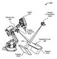
- FIG. 2illustrates an image-guided robotic radiosurgery system in one embodiment
- FIG. 3Aillustrates imaging and treatment delivery coordinate systems in one embodiment
- FIGS. 3B-3Eillustrate 2D-2D registration of x-ray images and DRRs in one embodiment
- FIG. 4is a flowchart illustrating global patient alignment in one embodiment
- FIGS. 5A and 5Billustrate spine segmentation and removal in one embodiment
- FIGS. 6A-6Cillustrate tumor visualization and segmentation in one embodiment
- FIG. 6Dillustrates a segmentation tool in one embodiment
- FIG. 7illustrates segmentation of a lung tumor in a treatment planning system in one embodiment
- FIGS. 8A and 8Billustrate regions of interest surrounding a radiation target in one embodiment
- FIG. 9illustrates the generation of multiple ROIs in one embodiment
- FIG. 10Aillustrates a 2D contoured lung tumor and a region of interest in the first projection of FIG. 8A in one embodiment
- FIG. 10Billustrates a search window in an in-treatment x-ray image in the first projection of the volume of interest of FIG. 10A ;
- FIG. 10Cillustrates the value of a similarity measure as a function of the location of a region of interest within a search window in one embodiment
- FIG. 10Dillustrates multi-level matching in one embodiment.
- FIGS. 11A and 11Billustrate shift correlation windows corresponding to correct tumor detection in one embodiment
- FIGS. 12A and 12Bare graphs illustrating a quality measure for correct target detection in one embodiment
- FIGS. 13A and 13Bare graphs illustrating a quality measure for incorrect target detection in one embodiment
- FIGS. 14A and 14Billustrate shift correlation windows corresponding to incorrect target detection in one embodiment
- FIGS. 15A and 15Billustrate search window reduction in one embodiment
- FIG. 16is a flowchart illustrating a method for target detection in one embodiment.
- FIG. 17is a block diagram illustrating a system in which embodiments of the invention may be implemented.
- x-ray imagemay mean a visible x-ray image (e.g., displayed on a video screen) or a digital representation of an x-ray image (e.g., a file corresponding to the pixel output of an x-ray detector).
- in-treatment x-ray imagemay refer to images captured at any point in time during a treatment delivery phase of a radiosurgery or radiotherapy procedure, which may include times when the radiation source is either on or off.
- CT imaging datamay be used herein as an exemplary 3D imaging modality. It will be appreciated that data from any type of 3D imaging modality such as CT data, MRI data, PET data, 3DRA data or the like may also be used in various embodiments of the invention.
- Embodiments of the present inventionmake use of pre-treatment image enhancement techniques, known as 2-dimensional (2D) contouring, to define limited regions of interest around the contour of a radiation target (e.g., a lung tumor). These regions of interest are expressed in regions in DRRs of limited size which are matched to search windows of limited size in in-treatment x-ray images in order to locate the radiation target.
- 2D contouring2-dimensional (2D) contouring
- regions of interestare expressed in regions in DRRs of limited size which are matched to search windows of limited size in in-treatment x-ray images in order to locate the radiation target.
- the limited sizes of the regions of interest in the DRRs and the search windows in the in-treatment x-ray imagesmay reduce the computational task of image registration and increase the speed of target detection.
- the reduced computation timemay also free processing time for the computation of detection quality measures, which provide a quality assurance step for the detection of low contrast targets.
- Embodiments of the inventionmay be described with respect to a particular type of pathological anatomy such as a lung tumor, for ease of discussion. In alternative embodiments, the techniques described herein may be used to detect and track other types of pathological anatomies in other organs (e.g., liver, pancreas, etc.).
- FIG. 1Ais a flowchart illustrating an overview of treatment planning and treatment delivery processes, in one embodiment, which will be described in greater detail below.
- treatment planning 100begins with the acquisition of 3D imaging data (operation 110 ) from a 3D imaging system such as a CT scanner, MRI scanner, etc. Segmentation of the 3D imaging data (operation 120 ) is performed to define and identify the boundaries of the radiation target, critical structures to avoid during treatment and/or bony structures such as the spine or cranium that may be used for patient alignment during treatment.
- the next operationis the generation of contours of the radiation target in 2D projections of the 3D imaging data that correspond to the projections of DRRs used during treatment delivery.
- Two-dimensional contouring methodsare known in the art, and generally employ gray level edge detection with different types of spatial operators such as the Sobel operator and the Frei-Chen operator.
- Treatment planningis next performed by a medical physicist or other clinician to achieve a specified radiation dose to the radiation target, with a specified level of homogeneity and conformality, while keeping the radiation dose to healthy tissue and critical structures below specified levels.
- DRRsmay be generated in real time during radiation treatment.
- sets of DRRsmay be generated from 3D imaging data having the spine and/or other bony structures removed to increase the visibility/contrast of the radiation target, if such structures would otherwise occlude or obscure the radiation target. Removal of these structures may be performed by manipulating voxel masks in the 3D imaging data as is known in the art.
- sets of DRRsmay be generated from the 3D imaging data with only the spine and, optionally, some surrounding tissue retained and with motion artifacts (e.g., breathing artifacts) removed, which may be used to enhance patient alignment as described below.
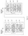
- the treatment delivery process 200begins with global patient alignment (pre-alignment) in the treatment system (operation 210 ), followed by target detection (operation 220 ), correlation of target motion with external markers (operation 240 ) and the delivery of radiation treatment in conformance with the treatment plan. These steps are expanded in FIG. 1B , and discussed below.
- Global patient alignmentmay be performed in six dimensions including three translations and three rotations, using DRRs and x-ray images of a large volume of interest, which may include identifiable landmarks such as fiducial markers and/or bony structures (e.g., the spine, the cranium) and/or pattern intensity variations that can be used for global alignment.
- the alignmentmay be performed using enhanced DRRs, such as those described above, containing segmented spine or other data.
- global positioningmay be performed by matching DRRs and x-ray images in one projection, two projections, or three or more projections depending on the geometry of the in-treatment imaging system
- radiation target detection(operation 220 ) may be performed.
- target detectionmay include the following steps, which are described in greater detail hereafter:
- the treatment delivery processcontinues at operation 240 by correlating the location of the target with external markers on the patient (which may be visually tracked by an independent optical tracking system (e.g., a laser tracking system) and initiating the capture of another set of live images.
- Operations 220 and 240may be repeated, tracking the radiation target until a correlation model is developed between the movement of the external markers and the detected locations of the radiation target.
- Operations 220 and 240may also be repeated to update the correlation model.
- FIG. 2illustrates the configuration of an image-guided, robotic-based radiation treatment system 200 , such as the CYBERKNIFE® Stereotactic Radiosurgery System manufactured by Accuray Incorporated of Sunnyvale, Calif., that may be used to implement embodiments of the invention.
- the radiation treatment sourceis a linear accelerator (LINAC) 201 mounted on the end of a robotic arm 202 having multiple (e.g., 5 or more) degrees of freedom in order to position the LINAC 201 to irradiate a pathological anatomy (target region or volume) with beams delivered from many angles, in many planes, in an operating volume around the patient. Treatment may involve beam paths with a single isocenter, multiple isocenters, or with a non-isocentric approach.
- LINAClinear accelerator
- the treatment delivery system of FIG. 2includes an in-treatment imaging system, which may include x-ray sources 203 A and 203 B and x-ray detectors (imagers) 204 A and 204 B.
- the two x-ray sources 203 A and 203 Bmay be mounted in fixed positions on the ceiling of an operating room and may be aligned to project imaging x-ray beams from two different angular positions (e.g., separated by 90 degrees) to intersect at a machine isocenter 205 (which provides a reference point for positioning the patient on a treatment couch 206 during treatment) and to illuminate imaging planes of respective detectors 204 A and 204 B after passing through the patient.
- a machine isocenter 205which provides a reference point for positioning the patient on a treatment couch 206 during treatment
- system 200may include more or less than two x-ray sources and more or less than two detectors, and any of the detectors may be movable rather than fixed and/or mounted below floor level. In yet other embodiments, the positions of the x-ray sources and the detectors may be interchanged.
- the first step in treatment planning 100after acquisition of the 3D imaging data is segmentation (operation 120 ).
- Medical image segmentationis the process of partitioning a 3D medical image (such as a CT, MRI, PET or 3DRA image) into regions that are homogeneous with respect to one or more characteristics or features (e.g., tissue type, density).
- segmentationis a step in treatment planning where the boundaries and volumes of a targeted pathological anatomy (e.g., a tumor or lesion) and critical anatomical structures (e.g., spinal chord) are defined and mapped into the treatment plan.
- the precision of the segmentationmay be critical to obtaining a high degree of conformality and homogeneity in the radiation dose during treatment of the pathological anatomy while sparing healthy tissue from unnecessary radiation.
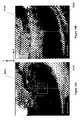
- FIGS. 5A and 5Billustrate one example.
- FIG. 5Aillustrates a DRR in one projection that is generated from an unmodified 3D image file.
- FIG. 5Billustrates a DRR generated from the same 3D image file after spine segmentation and elimination of non-spinal features.
- this type of DRRmay be used to enhance the initial global alignment of a patient within a treatment system (e.g., when fiducial markers have not been used).
- FIGS. 6A and 6Billustrate a different use of segmentation.
- FIG. 6Aillustrates a DRR from unmodified 3D scan data, where features of the spine 607 overlap the boundaries of a lung tumor 608 , making it difficult to define the tumor contour.
- FIG. 6Bthe spine has been segmented and deleted from the 3D scan data to produce a DRR with the tumor better visualized.
- FIG. 6Cillustrates how the tumor may also be segmented for 2D contour generation, as described below.
- the processes described abovemay be automated by a segmentation tool, such as the tool provided in the MultiPlanTM treatment planning system available from Accuray Incorporated of Sunnyvale, Calif.
- the segmentation toolmay be used to manipulate a patient's medical image (e.g., CT or other image volume such as MRI, PET, etc.). Alternatively, other tools may be used.
- FIG. 6Dis a screenshot 600 illustrating how the segmentation tool allows a user to delineate a spine in the volume of interest simultaneously from three cutting planes of the medical image: the axial plane 601 , the sagittal plane 602 and the coronal plane 603 .
- the contourcan be a solid contour when it is defined by a user, or it can be a dashed-line contour interpolated from adjacent contours by a computer.
- a usercan modify the contour by resizing it, scaling it or moving it.
- a projected silhouette contour 605 of the spine volume of interestis displayed on the sagittal plane 602 and coronal plane 603 .
- the centers of all user defined contours(such as contour 604 , for example) are connected as the central axis of the spine 606 .
- a usercan move, add or remove contours by moving or dragging the centers of the contours.
- the center of a contouris moved on the sagittal or coronal planes, the actual contour defined on the axial image slice is moved accordingly.
- a new contouris added at that position, with the contour automatically set to the interpolation of the two adjacent axial contours.
- the contouris removed from the volume of interest.
- the spineis delineated and stored in the geometrical format, it is converted to the volume format as a three-dimensional image volume containing only the voxels associated with the spine.
- FIG. 7is a screenshot 700 of a CT image illustrating a lung tumor 701 in the aforementioned axial, sagittal and coronal planes (MRI or another non-x-ray imaging modality may be used in conjunction with CT data to visualize a tumor when the x-ray density of the tumor is very close to that of its surrounding tissue, as in the case of lung tumors).
- MRIaxial, sagittal and coronal planes
- the same contouring tools described in respect to spine segmentation abovemay be used to segment the tumor in the 3D image and to provide data inputs to automatic 2D contour generation processes that may be used to create and overlay 2D tumor contours on DRRs during treatment delivery.
- the treatment planning processconcludes with the development of the actual treatment plan, generating DRRs and saving (e.g., digitally) the plan, DRRs and 2D target contours for subsequent use in treatment delivery (operations 140 and 150 ).
- the details of operations 140 and 150are known in the art and, accordingly are not described in detail.
- the first step in treatment deliveryis global patient alignment within the treatment delivery system (operation 210 ).
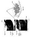
- FIG. 3Aillustrates the relationships among the 3D coordinate system of a treatment delivery system (such as treatment delivery system 200 ), the 2D coordinate system of an in-treatment imaging system (such as the in-treatment imaging system in treatment delivery system 200 ) and the 3D coordinate system of a 3D image (e.g., CT, MRI, PET, etc.).
- the coordinate system xyzwhere x is normal to, and pointing into, the plane of FIG.
- the projections A and Bare associated with the in-treatment imaging system where S A and S B represent x-ray sources (such as x-ray sources 103 A and 103 B) and O A and O B are the centers of the imaging planes of x-ray detectors (such as x-ray detectors 104 A and 104 B).
- S A and S Brepresent x-ray sources (such as x-ray sources 103 A and 103 B) and O A and O B are the centers of the imaging planes of x-ray detectors (such as x-ray detectors 104 A and 104 B).
- the projections A and Bare viewed from the directions O A S A and O B S B , respectively. It is these two 2D image projections which are compared against DRRs to achieve image registration and alignment, both for global patient positioning and for embodiments of radiation target tracking described herein.
- a 3D transformationmay be defined from coordinate system xyz to coordinate system x′y′z′ in FIG. 3A in terms of three translations ( ⁇ x, ⁇ y, ⁇ z) and three rotations ( ⁇ x , ⁇ y , ⁇ z ).
- a 3D rigid transformation between the two 3D coordinate systemscan be derived from basic trigonometry as:
- the 3D rigid transformationmay be decomposed into the in-plane transformation ( ⁇ x A , ⁇ y A , ⁇ A ) and two out-of-plane rotations ( ⁇ x A , ⁇ y′ ).
- the decompositionconsists of the in-plane transformation ( ⁇ x B , ⁇ y B , ⁇ B ) and two out-of-plane rotations ( ⁇ x B , ⁇ z′ ).
- 3B through 3Eillustrate the in-plane transformations and out-of-plane rotations described herein, where a 2D x-ray image is represented by plane 301 and the 2D DRR is represented by plane 302 .
- the 3D rigid transformation of equation (1)may be simplified by noting that the use of two projections over-constrains the solution to the six parameters of the 3D rigid transformation.
- the translation x A in projection Ais the same parameter as x B in projection B
- the out-of-plane rotation ⁇ x A in projection Ais the same as ⁇ x B in projection B.
- ⁇ A and ⁇ Bare geometric amplification factors (e.g., scale factors related to source-to-patient and patient-to-detector distances) for projections A and B, respectively.
- ⁇ x ′( ⁇ B ⁇ x B ⁇ A ⁇ x A )/2
- ⁇ y′⁇ A ⁇ y A
- ⁇ z′⁇ B ⁇ y B .
- the 2D in-plane transformation ( ⁇ x A , ⁇ y A , ⁇ A )may be estimated by a 2D to 2D image comparison, and the two out-of-plane rotations ( ⁇ x A , ⁇ y′ ) may be calculated by matching the x-ray image to the set of DRR images as described below, using similarity measures.
- the same processmay be used to solve the 2D in-plane transformation ( ⁇ x B , ⁇ y B , ⁇ B ) and the out-of-plane rotations ( ⁇ x B , ⁇ z′ ) for the projection B.
- the in-plane transformation and out-of-plane rotationsmay be obtained by registration between the x-ray image and the set of DRR images, independently for both projection A and projection B.
- the in-plane transformationcan be approximately described by ⁇ (x A , ⁇ Y A , ⁇ A ) when ⁇ y′ is small (e.g., less than 5°).
- These methodsgenerally employ the calculation of a similarity measure, followed by the application of a gradient search algorithm to maximize the similarity between the in-treatment x-ray images and selected DRRs.
- similarity measuresinclude (but are not limited to) normalized cross-section, entropy of the difference image, mutual information, gradient correlation, pattern intensity and gradient difference.
- a corresponding simplificationmay be made for projection B.
- ⁇ ⁇ ⁇ x( - ⁇ A ⁇ ⁇ ⁇ ⁇ x A + ⁇ B ⁇ ⁇ ⁇ ⁇ x B ) / 2
- ⁇ ⁇ ⁇ y( ⁇ A ⁇ ⁇ ⁇ ⁇ y A - ⁇ B ⁇ ⁇ ⁇ ⁇ y B ) / 2
- ⁇ ⁇ ⁇ ⁇ z( ⁇ A ⁇ ⁇ ⁇ ⁇ y A + ⁇ B ⁇ ⁇ ⁇ ⁇ y B ) / 2
- ⁇ x( ⁇ x A + ⁇ x B ) / 2
- ⁇ ⁇ y( ⁇ B - ⁇ A ) / 2
- ⁇ z( ⁇ B + ⁇ A ) / 2 . ( 4 )
- the 3D transformation required to align the 3D coordinate system of the patient in the treatment delivery system with the coordinate system of a 3D treatment planmay be completely defined by the two sets of four parameters ( ⁇ x A , ⁇ y A , ⁇ A , ⁇ x A ) and ( ⁇ x B , ⁇ y B , ⁇ B , ⁇ x B ).
- the process of global alignmentis illustrated schematically in FIG. 4 .
- the processbegins with the acquisition of in-treatment x-ray images (operation 401 ).
- operation 402the x-ray images are compared and registered, as described above, with DRR sets created from 3D scan data and imported from a treatment planning system.
- the results of the registrationare the 2 sets of 2D transformation parameters that are used in operation 403 to calculate the 3D transformation required in operation 404 to bring the patient into alignment.
- target detectionbegins with operation 221 , the definition of multiple regions of interest (ROIs), in multiple projections corresponding to the in-treatment imaging system, around the 2D contours of the radiation target created during treatment planning.
- ROIsregions of interest
- FIGS. 8A , 8 B and 9for the exemplary case of a lung tumor.
- FIGS. 8A and 8Billustrate, respectively, DRRs 800 A and 800 B in two projections (e.g., projections A and B) selected for direct target registration after the global patient alignment described above.
- the DRRshave been synthesized from 3D image data with spine removed to enhance the contrast of the tumor.
- a 2D tumor contour 801 Ahas been overlaid on DRR 800 A and an initial ROI 802 A in projection A has been generated around tumor contour 801 A.
- a 2D tumor contourhas been overlaid on DRR 800 B and an initial ROI 802 B in projection B has been generated around tumor contour 801 B.
- These initial ROIsmay be selected to conform closely to the dimensions of the tumor contours in the horizontal and vertical dimensions of their respective DRRs, such that the ROIs include the tumor contour and some tissue outside of the tumor contour.
- additional ROIsmay be defined that include more area than the initial ROI and less area than the initial ROI, in order to provide the opportunity for better tumor detection. For example, if the borders of the tumor are ill-defined and/or difficult to image using any of the normal 3D imaging techniques, then the 2D contour of the tumor generated in the treatment planning stage may include either more or less than all of the tumor. As a result, different sized ROIs may produce better tumor detection and/or treatment. These different sized ROIs are illustrated in FIG. 9 , where in addition to a contour-based ROI 802 , a larger ROI 803 and a smaller ROI 804 have been defined. In other embodiments, more or less than three ROIs may be used at the discretion of a clinician. In one embodiment, the step sizes between ROIs may vary from approximately 1 mm to approximately 5 mm, depending on the size of the tumor. However, any step size may be selected at the discretion of a clinician.
- a live image of the patientis captured in the multiple projections of the in-treatment imaging system.
- one of the projectionsis selected.
- one of the ROIsis selected for target detection.
- target registrationis performed to detect the target location by overlaying the selected ROI (containing the DRR image of the target) on the corresponding in-treatment x-ray image (which reflects the globally pre-aligned patient as described above) and performing a search within a search window in the in-treatment x-ray image.
- the search algorithmmay be the same as that used for global alignment (e.g., computation of a similarity measure and gradient searches to maximize the similarity), but constrained to the area of the search window.
- the searchmay be a deterministic search (e.g., a raster search) within the search window for a maximum similarity measure.
- the searchmay utilize multi-level matching, as described below, to speed up the registration process.
- FIGS. 10A-10Cillustrate the process.
- FIG. 10Ais a reproduction of the segmented DRR 800 A of FIG. 8A showing the 2D contour 801 A and region of interest 802 A.
- FIG. 10Billustrates the corresponding in-treatment x-ray image 810 A in projection A having a search window 803 A.
- the area of the search window 803 Amay be selected to be in the range of two to four times the area of the region of interest 802 A. In other embodiments, the area of the search window may be larger or smaller, as determined by a clinician based on experience and/or clinical data.
- Target detectionmay be performed by overlaying the region of interest 802 A in the search window 803 A of the in-treatment x-ray image 810 A, moving the region of interest 802 A within the search window 803 A (as shown by the several example locations of region of interest 802 A in search window 803 A in FIG. 10B ) and searching for a location that maximizes a similarity measure between the region of interest 802 A and the portion of the search window 803 A that the region of interest 802 A overlaps.
- the movement of the region of interest within the search windowdescribes a similarity measure surface 804 A which has a maximum value 805 A when the region of interest 802 A is properly aligned with the tumor in the in-treatment x-ray image.
- a multi-level searchmay be used to reduce the probability that a search will get stuck at a local maximum of the similarity surface 804 A, and not find the global maximum in the search window.
- an exemplary multi-level searchbegins at a low resolution search level 809 and proceeds to higher resolution levels 808 , 807 and 806 .
- the lowest resolution level, 809the dimensions of the selected ROI and the search window are reduced by a scale factor by sub-sampling.
- the similarity measureis maximized at the lowest resolution, the results are passed to the next higher resolution level where the similarity measure is again maximized, and so on until the similarity measure is maximized at the highest resolution level.
- FIG. 10Dillustrates one embodiment with four resolution levels where the resolution is doubled at each successive level. Other embodiments may use more or less than four levels and different resolution factors at each level.
- a quality measuremay be determined.
- a first set of shift correlation windowsis defined around the nominal location of the target as determined by the preceding search algorithm in operation 225 .
- Each shift correlation windowis offset from the nominal target location in different amounts, so that each shift correlation window contains different portions of the target and surrounding tissue.
- each shift correlation windowis registered in the in-treatment x-ray image (e.g., as in operation 225 ) to find a second, matching set of shift correlation windows in the corresponding in-treatment x-ray image.
- FIG. 11Aillustrates a first group of shift correlation windows 815 A defined within the DRR 800 A. The same group of shift correlation windows 815 A is overlaid in the in-treatment x-ray image 810 A in FIG. 11B .
- the set of matching shift correlation windows in the in-treatment x-ray imagewill match the locations of the first set of shift correlation windows with little or no movement. That is, the final locations of each matching shift correlation window will be close to the initial locations of the first set of shift correlation windows when the best match has been achieved. Conversely, if the initial target detection was incorrect, then the final locations of the matching shift correlation windows may be significantly different from the initial locations of the first set of shift correlation windows when the best match has been achieved.
- the difference between initial locations and final locationsmay be characterized as displacements in the x and y coordinates of the in-treatment x-ray image between the first set of shift correlation windows and the matching set of shift correlation windows.
- a quality measuremay be calculated, for example, as an average displacement in the x and y directions, as illustrated in FIGS. 12A and 12B , for the example of 25 different shift correlation windows.
- the displacements of the shift correlation windowsfall within a range with an average value approximately equal to zero.
- the choice of the number of shift correlation windows to use, and the displacement of each windowis based on the experience of a clinician and/or clinical data. In other embodiments, different quality measures may be used (e.g., sum of absolute or squared distances).
- the processasks, at operation 229 if all ROIs in the selected projected have been tested, and if not, then operations 224 - 228 are repeated. If all of the ROIs in the selected projection have been tested, then the process asks, at operation 230 , if all projections have been tested. If not, then operations 223 through 229 are repeated until all projections have been tested.
- the quality of the in-treatment x-ray imagesmay not be the same in every projection of a volume of interest because the x-rays travel through different paths with different anatomical structures.
- the quality of tumor detection in each projectionmay be higher in one projection.
- operations 227 and 228may include additional steps.
- a high quality target detection in one projectionmay be used to improve target detection in another projection by constraining a search window in the other projection.
- FIG. 15Aillustrates an in-treatment x-ray image 850 A in a first projection of a volume of interest where a tumor 851 A has been located within a search window 852 A with correct tumor detection as determined by a shift correlation quality measure as described above.
- FIG. 15Billustrates an in-treatment x-ray of the volume of interest in a second projection where it is assumed that an initial search has incorrectly detected tumor 851 B (the projection of tumor 851 A in the second projection) and produced a low quality measure.
- images 850 A and 850 Bshare the same x-axis (see FIG. 3A and discussion above)
- the x-coordinates of tumor 851 Bare defined by the x-coordinates of tumor 851 A and a constrained search window 852 B may be defined in image 850 B that limits the search in the x-axis and allows the search in the y-axis of image 850 B to be optimized.
- FIG. 16is a flowchart illustrating one embodiment of a method 500 for target detection.
- operation 501one or more ROIs are generated in the DRRs in the projections corresponding to a patient's global pre-alignment (i.e., operation 210 ), where each ROI is defined relative to a 2D contour of the radiation target.
- operation 502the ROIs in the DRRs are matched with corresponding in-treatment x-ray images in each projection of the treatment delivery system.
- Operation 502includes operations 503 and 504 .
- operation 503the ROI is moved within a search window in the in-treatment x-ray image in each projection according to a search algorithm to maximize a similarity measure.
- operation 504a quality measure for target detection in each projection is determined.
- Operation 504includes operations 505 through 509 .
- Operation 505generates a first set of shift correlation windows in a selected DRR.
- operation 506the first set of shift correlation windows is registered in the corresponding in-treatment x-ray image to find a second set of shift correlation windows in the corresponding in-treatment x-ray image that matches the first set of shift correlation windows, such that the first and second sets of shift correlation windows form matching pairs of shift correlation windows.
- Operation 507determines displacements between the matching pairs of shift correlation windows from the first set of shift correlation windows and the second set of shift correlation windows.
- Operation 508assigns a quality measure for tumor detection in each projection of the VOI.
- operation 509selects a ROI in a first projection having a highest quality measure in order to limit the search window in a second projection.
- operation 510searches within a limited search window in the second projection to maximize the quality of the tumor detection in the second projection.
- operation 511the next ROI in each projection is selected and the method repeats at operation 501 .
- a methodincludes segmenting and removing bony structures from 3D imaging data of a volume of interest (VOI) to visualize a radiation target in DRRs generated from the 3D imaging data; matching the DRRs with in-treatment x-ray images; selecting a region of interest in a DRR including a 2D contour of the radiation target; and searching within a search window in a matching in-treatment x-ray image to match the ROI to a corresponding ROI in the matching in-treatment x-ray image.
- VTIvolume of interest
- FIG. 17illustrates one embodiment of systems 1300 that may be used in performing radiation treatment in which embodiments of the present invention may be implemented.
- system 1300may include a diagnostic imaging system 1000 , a treatment planning system 2000 and a treatment delivery system 3000 .
- Diagnostic imaging system 1000may be any system capable of producing medical diagnostic images of a patient that may be used for subsequent medical diagnosis, treatment planning and/or treatment delivery.
- diagnostic imaging system 1000may be a computed tomography (CT) system, a magnetic resonance imaging (MRI) system, a positron emission tomography (PET) system, an ultrasound system or the like.
- CTcomputed tomography
- MRImagnetic resonance imaging
- PETpositron emission tomography
- ultrasound systemor the like.
- diagnostic imaging system 1000is discussed at times in relation to a CT imaging modality. However, other imaging modalities such as those above may also be used.
- Diagnostic imaging system 1000includes an imaging source 1010 to generate an imaging beam (e.g., x-rays, ultrasonic waves, radio frequency waves, etc.) and an imaging detector 1020 to detect and receive the beam generated by imaging source 1010 , or a secondary beam or emission stimulated by the beam from the imaging source (e.g., in an MRI or PET scan).
- diagnostic imaging system 1000may include two or more diagnostic X-ray sources and two or more corresponding imaging detectors.
- two x-ray sourcesmay be disposed around a patient to be imaged, fixed at an angular separation from each other (e.g., 90 degrees, 45 degrees, etc.) and aimed through the patient toward (an) imaging detector(s) which may be diametrically opposed to the x-ray sources.
- an imaging detector(s)which may be diametrically opposed to the x-ray sources.
- a single large imaging detector, or multiple imaging detectors,may also be used that would be illuminated by each x-ray imaging source.
- other numbers and configurations of imaging sources and imaging detectorsmay be used.
- the imaging source 1010 and the imaging detector 1020may be coupled to a digital processing system 1030 to control the imaging operation and process image data.
- Diagnostic imaging system 1000includes a bus or other means 1035 for transferring data and commands among digital processing system 1030 , imaging source 1010 and imaging detector 1020 .
- Digital processing system 1030may include one or more general-purpose processors (e.g., a microprocessor), special purpose processor such as a digital signal processor (DSP) or other type of device such as a controller or field programmable gate array (FPGA).
- DSPdigital signal processor
- FPGAfield programmable gate array
- Digital processing system 1030may also include other components (not shown) such as memory, storage devices, network adapters and the like.
- Digital processing system 1030may be configured to generate digital diagnostic images in a standard format, such as the DICOM (Digital Imaging and Communications in Medicine) format, for example. In other embodiments, digital processing system 1030 may generate other standard or non-standard digital image formats. Digital processing system 1030 may transmit diagnostic image files (e.g., the aforementioned DICOM formatted files) to treatment planning system 2000 over a data link 1500 , which may be, for example, a direct link, a local area network (LAN) link or a wide area network (WAN) link such as the Internet. In addition, the information transferred between systems may either be pulled or pushed across the communication medium connecting the systems, such as in a remote diagnosis or treatment planning configuration. In remote diagnosis or treatment planning, a user may utilize embodiments of the present invention to diagnose or treatment plan despite the existence of a physical separation between the system user and the patient.
- DICOMDigital Imaging and Communications in Medicine
- Treatment planning system 2000includes a processing device 2010 to receive and process image data.
- Processing device 2010may represent one or more general-purpose processors (e.g., a microprocessor), special purpose processor such as a digital signal processor (DSP) or other type of device such as a controller or field programmable gate array (FPGA).
- DSPdigital signal processor
- FPGAfield programmable gate array
- Processing device 2010may be configured to execute instructions for performing treatment planning and/or image processing operations discussed herein, such as the spine segmentation tool described herein.
- Treatment planning system 2000may also include system memory 2020 that may include a random access memory (RAM), or other dynamic storage devices, coupled to processing device 2010 by bus 2055 , for storing information and instructions to be executed by processing device 2010 .
- System memory 2020also may be used for storing temporary variables or other intermediate information during execution of instructions by processing device 2010 .
- System memory 2020may also include a read only memory (ROM) and/or other static storage device coupled to bus 2055 for storing static information and instructions for processing device 2010 .
- ROMread only memory
- Treatment planning system 2000may also include storage device 2030 , representing one or more storage devices (e.g., a magnetic disk drive or optical disk drive) coupled to bus 2055 for storing information and instructions.
- Storage device 2030may be used for storing instructions for performing the treatment planning steps discussed herein and/or for storing 3D imaging data and DRRs as discussed herein.
- Processing device 2010may also be coupled to a display device 2040 , such as a cathode ray tube (CRT) or liquid crystal display (LCD), for displaying information (e.g., a 2D or 3D representation of the VOI) to the user.
- a display device 2040such as a cathode ray tube (CRT) or liquid crystal display (LCD)
- An input device 2050such as a keyboard, may be coupled to processing device 2010 for communicating information and/or command selections to processing device 2010 .
- One or more other user input devicese.g., a mouse, a trackball or cursor direction keys
- treatment planning system 2000represents only one example of a treatment planning system, which may have many different configurations and architectures, which may include more components or fewer components than treatment planning system 2000 and which may be employed with the present invention. For example, some systems often have multiple buses, such as a peripheral bus, a dedicated cache bus, etc.
- the treatment planning system 2000may also include MIRIT (Medical Image Review and Import Tool) to support DICOM import (so images can be fused and targets delineated on different systems and then imported into the treatment planning system for planning and dose calculations), expanded image fusion capabilities that allow the user to treatment plan and view dose distributions on any one of various imaging modalities (e.g., MRI, CT, PET, etc.).
- MIRITMedical Image Review and Import Tool
- DICOM importso images can be fused and targets delineated on different systems and then imported into the treatment planning system for planning and dose calculations
- expanded image fusion capabilitiesthat allow the user to treatment plan and view dose distributions on any one of various imaging modalities (e.g., MRI,
- Treatment planning system 2000may share its database (e.g., data stored in storage device 2030 ) with a treatment delivery system, such as treatment delivery system 3000 , so that it may not be necessary to export from the treatment planning system prior to treatment delivery.
- Treatment planning system 2000may be linked to treatment delivery system 3000 via a data link 2500 , which may be a direct link, a LAN link or a WAN link as discussed above with respect to data link 1500 .
- data links 1500 and 2500are implemented as LAN or WAN connections, any of diagnostic imaging system 1000 , treatment planning system 2000 and/or treatment delivery system 3000 may be in decentralized locations such that the systems may be physically remote from each other.
- any of diagnostic imaging system 1000 , treatment planning system 2000 and/or treatment delivery system 3000may be integrated with each other in one or more systems.
- Treatment delivery system 3000includes a therapeutic and/or surgical radiation source 3010 to administer a prescribed radiation dose to a target volume in conformance with a treatment plan.
- Treatment delivery system 3000may also include an imaging system 3020 to capture intra-treatment images of a patient volume (including the target volume) for registration or correlation with the diagnostic images described above in order to position the patient with respect to the radiation source.
- Imaging system 3020may include any of the imaging systems described above.
- Treatment delivery system 3000may also include a digital processing system 3030 to control radiation source 3010 , imaging system 3020 and a patient support device such as a treatment couch 3040 .
- Digital processing system 3030may be configured to register 2D radiographic images from imaging system 3020 , from two or more stereoscopic projections, with digitally reconstructed radiographs (e.g., DRRs from segmented 3D imaging data) generated by digital processing system 1030 in diagnostic imaging system 1000 and/or DRRs generated by processing device 2010 in treatment planning system 2000 .
- Digital processing system 3030may include one or more general-purpose processors (e.g., a microprocessor), special purpose processor such as a digital signal processor (DSP) or other type of device such as a controller or field programmable gate array (FPGA).
- Digital processing system 3030may also include other components (not shown) such as memory, storage devices, network adapters and the like.
- Digital processing system 3030may be coupled to radiation source 3010 , imaging system 3020 and treatment couch 3040 by a bus 3045 or other type of control and communication interface.
- Digital processing system 3030may implement methods (e.g., such as method 1200 described above) to register images obtained from imaging system 3020 with pre-operative treatment planning images in order to align the patient on the treatment couch 3040 within the treatment delivery system 3000 , and to precisely position the radiation source with respect to the target volume.
- methodse.g., such as method 1200 described above
- the treatment couch 3040may be coupled to another robotic arm (not illustrated) having multiple (e.g., 5 or more) degrees of freedom.
- the couch armmay have five rotational degrees of freedom and one substantially vertical, linear degree of freedom.
- the couch armmay have six rotational degrees of freedom and one substantially vertical, linear degree of freedom or at least four rotational degrees of freedom.
- the couch armmay be vertically mounted to a column or wall, or horizontally mounted to pedestal, floor, or ceiling.
- the treatment couch 3040may be a component of another mechanical mechanism, such as the Axum® treatment couch developed by Accuray Incorporated of California, or be another type of conventional treatment table known to those of ordinary skill in the art.
- treatment delivery system 3000may be another type of treatment delivery system, for example, a gantry based (isocentric) intensity modulated radiotherapy (IMRT) system.
- a radiation sourcee.g., a LINAC
- LINACa radiation source
- Radiationis then delivered from several positions on the circular plane of rotation.
- the shape of the radiation beamis defined by a multi-leaf collimator that allows portions of the beam to be blocked, so that the remaining beam incident on the patient has a pre-defined shape.
- the resulting systemgenerates arbitrarily shaped radiation beams that intersect each other at the isocenter to deliver a dose distribution to the target region.
- the optimization algorithmselects subsets of the main beam and determines the amount of time that the patient should be exposed to each subset, so that the prescribed dose constraints are best met.
- the gantry based systemmay have a gimbaled radiation source head assembly.
- treatmentmay refer generally to the effectuation of an operation controlled by the treatment planning system, such as the application of a beam (e.g., radiation, acoustic, etc.) and “target” may refer to a non-anatomical object or area.
- a beame.g., radiation, acoustic, etc.
- targetmay refer to a non-anatomical object or area.
- Embodiments of the present inventioninclude various operations, which are described herein. These operations may be performed by hardware components, software, firmware or a combination thereof. Any of the signals provided over various buses described herein may be time multiplexed with other signals and provided over one or more common buses. Additionally, the interconnection between circuit components or blocks may be shown as buses or as single signal lines. Each of the buses may alternatively be one or more single signal lines and each of the single signal lines may alternatively be buses.
- Certain embodimentsmay be implemented as a computer program product that may include instructions stored on a machine-readable medium. These instructions may be used to program a general-purpose or special-purpose processor to perform the described operations.
- a machine-readable mediumincludes any mechanism for storing or transmitting information in a form (e.g., software, processing application) readable by a machine (e.g., a computer).
- the machine-readable mediummay include, but is not limited to, magnetic storage medium (e.g., floppy diskette); optical storage medium (e.g., CD-ROM); magneto-optical storage medium; read-only memory (ROM); random-access memory (RAM); erasable programmable memory (e.g., EPROM and EEPROM); flash memory; electrical, optical, acoustical, or other form of propagated signal (e.g., carrier waves, infrared signals, digital signals, etc.); or another type of medium suitable for storing electronic instructions.
- magnetic storage mediume.g., floppy diskette
- optical storage mediume.g., CD-ROM
- magneto-optical storage mediume.g., magneto-optical storage medium
- ROMread-only memory
- RAMrandom-access memory
- EPROM and EEPROMerasable programmable memory
- flash memoryelectrical, optical, acoustical, or other form of propagated signal (e.g., carrier waves, in
- some embodimentsmay be practiced in distributed computing environments where the machine-readable medium is stored on and/or executed by more than one computer system.
- the information transferred between computer systemsmay either be pulled or pushed across the communication medium connecting the computer systems such as in a remote diagnosis or monitoring system.
- remote diagnosis or monitoringa user may diagnose or monitor a patient despite the existence of a physical separation between the user and the patient.
- the treatment delivery systemmay be remote from the treatment planning system.
Landscapes
- Engineering & Computer Science (AREA)
- Health & Medical Sciences (AREA)
- Biomedical Technology (AREA)
- General Health & Medical Sciences (AREA)
- Veterinary Medicine (AREA)
- Radiology & Medical Imaging (AREA)
- Life Sciences & Earth Sciences (AREA)
- Animal Behavior & Ethology (AREA)
- Pathology (AREA)
- Public Health (AREA)
- Nuclear Medicine, Radiotherapy & Molecular Imaging (AREA)
- Multimedia (AREA)
- Computer Vision & Pattern Recognition (AREA)
- Physics & Mathematics (AREA)
- General Physics & Mathematics (AREA)
- Theoretical Computer Science (AREA)
- Apparatus For Radiation Diagnosis (AREA)
- Radiation-Therapy Devices (AREA)
Abstract
Description
Δx′=(αBΔxB−αAΔxA)/2, Δy′=αAΔyA, Δz′=αBΔyB. (2)
Δθy′=ΔθB, Δθz′=ΔθA. (3)
Claims (42)
Priority Applications (7)
| Application Number | Priority Date | Filing Date | Title |
|---|---|---|---|
| US11/592,789US7894649B2 (en) | 2006-11-02 | 2006-11-02 | Target tracking using direct target registration |
| PCT/US2007/021884WO2008057166A2 (en) | 2006-11-02 | 2007-10-11 | Target tracking using direct target registration |
| JP2009535265AJP2010508895A (en) | 2006-11-02 | 2007-10-11 | Target tracking using direct target registration |
| CN200780040628.2ACN101553281B (en) | 2006-11-02 | 2007-10-11 | Use the target following of direct target registration |
| EP18194330.9AEP3467773A1 (en) | 2006-11-02 | 2007-10-11 | Target tracking using direct target registration |
| EP07852723.1AEP2061559B1 (en) | 2006-11-02 | 2007-10-11 | Target tracking using direct target registration |
| US13/010,631US8090175B2 (en) | 2006-11-02 | 2011-01-20 | Target tracking using direct target registration |
Applications Claiming Priority (1)
| Application Number | Priority Date | Filing Date | Title |
|---|---|---|---|
| US11/592,789US7894649B2 (en) | 2006-11-02 | 2006-11-02 | Target tracking using direct target registration |
Related Child Applications (1)
| Application Number | Title | Priority Date | Filing Date |
|---|---|---|---|
| US13/010,631ContinuationUS8090175B2 (en) | 2006-11-02 | 2011-01-20 | Target tracking using direct target registration |
Publications (2)
| Publication Number | Publication Date |
|---|---|
| US20080130825A1 US20080130825A1 (en) | 2008-06-05 |
| US7894649B2true US7894649B2 (en) | 2011-02-22 |
Family
ID=39364964
Family Applications (2)
| Application Number | Title | Priority Date | Filing Date |
|---|---|---|---|
| US11/592,789Active2029-12-23US7894649B2 (en) | 2006-11-02 | 2006-11-02 | Target tracking using direct target registration |
| US13/010,631ActiveUS8090175B2 (en) | 2006-11-02 | 2011-01-20 | Target tracking using direct target registration |
Family Applications After (1)
| Application Number | Title | Priority Date | Filing Date |
|---|---|---|---|
| US13/010,631ActiveUS8090175B2 (en) | 2006-11-02 | 2011-01-20 | Target tracking using direct target registration |
Country Status (5)
| Country | Link |
|---|---|
| US (2) | US7894649B2 (en) |
| EP (2) | EP3467773A1 (en) |
| JP (1) | JP2010508895A (en) |
| CN (1) | CN101553281B (en) |
| WO (1) | WO2008057166A2 (en) |
Cited By (61)
| Publication number | Priority date | Publication date | Assignee | Title |
|---|---|---|---|---|
| US20090182311A1 (en)* | 2008-01-11 | 2009-07-16 | Oraya Therapeutics, Inc. | System and method for positioning and stabilizing an eye |
| US20100067657A1 (en)* | 2006-12-13 | 2010-03-18 | Oraya Therapeutics, Inc. | Orthovoltage radiotherapy |
| US20100080415A1 (en)* | 2008-09-29 | 2010-04-01 | Restoration Robotics, Inc. | Object-tracking systems and methods |
| US20100215149A1 (en)* | 2009-02-23 | 2010-08-26 | Kabushiki Kaisha Toshiba | X-ray diagnosis apparatus |
| US20110081001A1 (en)* | 2007-12-23 | 2011-04-07 | Oraya Therapeutics, Inc. | Methods and devices for orthovoltage ocular radiotherapy and treatment planning |
| US20120069968A1 (en)* | 2010-09-17 | 2012-03-22 | Accuray Incorporated | Image alignment |
| US20120116224A1 (en)* | 2010-11-08 | 2012-05-10 | General Electric Company | System and method for ultrasound imaging |
| US8320524B2 (en) | 2006-10-16 | 2012-11-27 | Oraya Therapeutics, Inc. | Orthovoltage radiotherapy |
| US20130010924A1 (en)* | 2011-06-06 | 2013-01-10 | Toshiba Medical Systems Corporation | Medical image processing apparatus |
| US8363783B2 (en) | 2007-06-04 | 2013-01-29 | Oraya Therapeutics, Inc. | Method and device for ocular alignment and coupling of ocular structures |
| US8503609B2 (en) | 2007-12-23 | 2013-08-06 | Oraya Therapeutics, Inc. | Methods and devices for detecting, controlling, and predicting radiation delivery |
| US20130216026A1 (en)* | 2010-02-18 | 2013-08-22 | Varian Medical Systems International Ag | Method and system for treating moving target |
| US20140222391A1 (en)* | 2010-03-19 | 2014-08-07 | Hologic, Inc. | System and Method for Generating Enhanced Density Distribution in a three Dimensional Model of a Structure for Use in Skeletal Assessment Using a Limited Number of Two Dimensional Views |
| US8818105B2 (en) | 2011-07-14 | 2014-08-26 | Accuray Incorporated | Image registration for image-guided surgery |
| US8911453B2 (en) | 2010-12-21 | 2014-12-16 | Restoration Robotics, Inc. | Methods and systems for directing movement of a tool in hair transplantation procedures |
| US20150131780A1 (en)* | 2012-07-13 | 2015-05-14 | Mitsubishi Electric Corporation | X-ray positioning apparatus, x-ray positioning method, and attentional image photographing method |
| US20150250442A1 (en)* | 2014-03-10 | 2015-09-10 | Kabushiki Kaisha Toshiba | X-ray image diagnostic apparatus |
| US20150283697A1 (en)* | 2014-04-07 | 2015-10-08 | Daegu Gyeongbuk Institute Of Science And Technology | Robot |
| US9230322B2 (en) | 2014-04-04 | 2016-01-05 | Kabushiki Kaisha Toshiba | Image processor, treatment system, and image processing method |
| US20160023019A1 (en)* | 2014-07-25 | 2016-01-28 | Varian Medical Systems, Inc | Imaging based calibration systems, devices, and methods |
| US9275302B1 (en)* | 2012-08-24 | 2016-03-01 | Amazon Technologies, Inc. | Object detection and identification |
| WO2016061142A1 (en) | 2014-10-14 | 2016-04-21 | Novartis Ag | Antibody molecules to pd-l1 and uses thereof |
| US9392965B2 (en) | 2013-03-14 | 2016-07-19 | Restoration Robotics, Inc. | Method and apparatus for determining a change in tension of a body surface |
| US9408691B2 (en) | 2013-03-14 | 2016-08-09 | Restoration Robotics, Inc. | Locator device for medical procedures on the body surface and method of its use |
| KR101661901B1 (en) | 2015-11-10 | 2016-10-05 | 한국원자력연구원 | Apparatus for compensating weight of linac for radiotherapy |
| KR101673931B1 (en) | 2015-11-10 | 2016-11-08 | 한국원자력연구원 | Apparatus for radiotherapy |
| US9498289B2 (en) | 2010-12-21 | 2016-11-22 | Restoration Robotics, Inc. | Methods and systems for directing movement of a tool in hair transplantation procedures |
| CN106422088A (en)* | 2015-08-11 | 2017-02-22 | 株式会社东芝 | Radiation therapy device and radiation therapy method |
| US20170291042A1 (en)* | 2016-04-12 | 2017-10-12 | Shimadzu Corporation | Positioning apparatus and method of positioning |
| US9895559B2 (en)* | 2014-04-07 | 2018-02-20 | Daegu Gyeongbuk Institute Of Science And Technology | Robot |
| US20180280727A1 (en)* | 2017-03-30 | 2018-10-04 | Shimadzu Corporation | Positioning apparatus and method of positioning |
| US20190060674A1 (en)* | 2017-08-29 | 2019-02-28 | Sensus Healthcare, Inc. | Robotic iort x-ray radiation system with calibration well |
| US10607802B2 (en) | 2017-03-31 | 2020-03-31 | Sensus Healthcare, Inc. | Three-dimensional beam forming X-ray source |
| US10646726B2 (en) | 2016-07-13 | 2020-05-12 | Sensus Healthcare, Inc. | Robotic intraoperative radiation therapy |
| AU2016228944B2 (en)* | 2015-03-12 | 2020-07-16 | Leo Cancer Care, Inc. | Method and system for in situ targeting of objects |
| US10940334B2 (en) | 2018-10-19 | 2021-03-09 | Sensus Healthcare, Inc. | Systems and methods for real time beam sculpting intra-operative-radiation-therapy treatment planning |
| US11040221B2 (en) | 2019-08-13 | 2021-06-22 | Elekta Ltd. | Adaptive radiation therapy using composite imaging slices |
| US11045667B2 (en) | 2017-07-18 | 2021-06-29 | Sensus Healthcare, Inc. | Real-time x-ray dosimetry in intraoperative radiation therapy |
| US11135449B2 (en) | 2017-05-04 | 2021-10-05 | Intraop Medical Corporation | Machine vision alignment and positioning system for electron beam treatment systems |
| US11141225B2 (en) | 2017-02-21 | 2021-10-12 | Koh Young Technology Inc. | Image matching device and image matching method |
| US11295449B2 (en) | 2016-11-21 | 2022-04-05 | Asto CT, Inc. | Three-dimensional tracking of a target in a body |
| US20220189080A1 (en)* | 2016-02-16 | 2022-06-16 | Brainlab Ag | Determination of Dynamic DRRs |
| US11504548B2 (en) | 2018-08-02 | 2022-11-22 | Mayo Foundation For Medical Education And Research | Systems and methods for quality control in image-guided radiotherapy |
| US20230097277A1 (en)* | 2021-09-29 | 2023-03-30 | Siemens Heal Thineers International Ag | On-line adaptive deep inspiration breath-hold treatment |
| US11672491B2 (en) | 2018-03-30 | 2023-06-13 | Empyrean Medical Systems, Inc. | Validation of therapeutic radiation treatment |
| US11712584B1 (en)* | 2022-05-24 | 2023-08-01 | Accuray Incorporated | Prospective and retrospective on-line adaptive radiotherapy |
| US11750794B2 (en) | 2015-03-24 | 2023-09-05 | Augmedics Ltd. | Combining video-based and optic-based augmented reality in a near eye display |
| US11766296B2 (en) | 2018-11-26 | 2023-09-26 | Augmedics Ltd. | Tracking system for image-guided surgery |
| US11801115B2 (en) | 2019-12-22 | 2023-10-31 | Augmedics Ltd. | Mirroring in image guided surgery |
| US11896445B2 (en) | 2021-07-07 | 2024-02-13 | Augmedics Ltd. | Iliac pin and adapter |
| US11974887B2 (en) | 2018-05-02 | 2024-05-07 | Augmedics Ltd. | Registration marker for an augmented reality system |
| US11980506B2 (en) | 2019-07-29 | 2024-05-14 | Augmedics Ltd. | Fiducial marker |
| US12044856B2 (en) | 2022-09-13 | 2024-07-23 | Augmedics Ltd. | Configurable augmented reality eyewear for image-guided medical intervention |
| US12150821B2 (en) | 2021-07-29 | 2024-11-26 | Augmedics Ltd. | Rotating marker and adapter for image-guided surgery |
| US12178666B2 (en) | 2019-07-29 | 2024-12-31 | Augmedics Ltd. | Fiducial marker |
| US12186028B2 (en) | 2020-06-15 | 2025-01-07 | Augmedics Ltd. | Rotating marker for image guided surgery |
| US12239385B2 (en) | 2020-09-09 | 2025-03-04 | Augmedics Ltd. | Universal tool adapter |
| US12354227B2 (en) | 2022-04-21 | 2025-07-08 | Augmedics Ltd. | Systems for medical image visualization |
| US12417595B2 (en) | 2021-08-18 | 2025-09-16 | Augmedics Ltd. | Augmented-reality surgical system using depth sensing |
| US12420116B2 (en) | 2019-09-14 | 2025-09-23 | Intraop Medical Corporation | Methods and systems for using and controlling higher dose rate ionizing radiation in short time intervals |
| US12440702B2 (en)* | 2022-04-26 | 2025-10-14 | Anzal Medical Co., Ltd. | Radiation treatment system comprising a CT apparatus, a treatment planning apparatus, and a radiation control apparatus, radiation control method, and storage medium |
Families Citing this family (75)
| Publication number | Priority date | Publication date | Assignee | Title |
|---|---|---|---|---|
| EP1720173A1 (en)* | 2005-05-06 | 2006-11-08 | Deutsches Krebsforschungszentrum Stiftung des öffentlichen Rechts | Collimator for collimating a beam of high energy rays |
| EP1892668B1 (en)* | 2006-08-22 | 2012-10-03 | BrainLAB AG | Registration of imaging data |
| US8193508B2 (en)* | 2007-12-05 | 2012-06-05 | Navotek Medical Ltd. | Detecting photons in the presence of a pulsed radiation beam |
| US8086004B2 (en)* | 2008-01-15 | 2011-12-27 | Accuray Incorporated | Use of a single X-ray image for quality assurance of tracking |
| US8017915B2 (en) | 2008-03-14 | 2011-09-13 | Reflexion Medical, Inc. | Method and apparatus for emission guided radiation therapy |
| WO2010009264A1 (en)* | 2008-07-16 | 2010-01-21 | Boris Oreper | Irradiation system including an electron-beam scanner |
| JP2010069086A (en)* | 2008-09-19 | 2010-04-02 | Toshiba Corp | Radiation therapy system and image display method |
| US8457372B2 (en)* | 2008-09-30 | 2013-06-04 | Accuray Incorporated | Subtraction of a segmented anatomical feature from an acquired image |
| WO2010044852A2 (en)* | 2008-10-14 | 2010-04-22 | University Of Florida Research Foundation, Inc. | Imaging platform to provide integrated navigation capabilities for surgical guidance |
| RU2564079C2 (en)* | 2008-12-11 | 2015-09-27 | Конинклейке Филипс Электроникс Н.В. | System and method for formation of image of patient's internal and external areas |
| US8792614B2 (en) | 2009-03-31 | 2014-07-29 | Matthew R. Witten | System and method for radiation therapy treatment planning using a memetic optimization algorithm |
| US20110050692A1 (en)* | 2009-09-01 | 2011-03-03 | Accuray Incorporated | Interpolating and rendering sub-phases of a 4d dataset |
| US8934605B2 (en) | 2010-02-24 | 2015-01-13 | Accuray Incorporated | Gantry image guided radiotherapy system and related treatment delivery methods |
| US9687200B2 (en) | 2010-06-08 | 2017-06-27 | Accuray Incorporated | Radiation treatment delivery system with translatable ring gantry |
| WO2011156526A2 (en) | 2010-06-08 | 2011-12-15 | Accuray, Inc. | Imaging methods and target tracking for image-guided radiation treatment |
| WO2012019162A1 (en) | 2010-08-06 | 2012-02-09 | Accuray, Inc. | Systems and methods for real-time tumor tracking during radiation treatment using ultrasound imaging |
| US8824630B2 (en) | 2010-10-29 | 2014-09-02 | Accuray Incorporated | Method and apparatus for treating a target's partial motion range |
| US8849633B2 (en)* | 2010-10-29 | 2014-09-30 | Accuray Incorporated | Method and apparatus for selecting a tracking method to use in image guided treatment |
| US8951266B2 (en) | 2011-01-07 | 2015-02-10 | Restoration Robotics, Inc. | Methods and systems for modifying a parameter of an automated procedure |
| US8536547B2 (en) | 2011-01-20 | 2013-09-17 | Accuray Incorporated | Ring gantry radiation treatment delivery system with dynamically controllable inward extension of treatment head |
| US9364687B2 (en) | 2011-01-21 | 2016-06-14 | Headwater Partners Ii Llc | Imaging observation timing based on radiation treatment system element delay |
| WO2012100270A2 (en) | 2011-01-21 | 2012-07-26 | Headwater Partners Ii Llc | Tracking of tumor location for targeted radiation treatment |
| US9283404B2 (en)* | 2011-01-21 | 2016-03-15 | Headwater Partners Ii Llc | Imaging observation timing for assisting radiation treatment |
| US9406411B2 (en) | 2011-02-08 | 2016-08-02 | Accuray Incorporated | Automatic calibration for device with controlled motion range |
| WO2012120405A1 (en)* | 2011-03-04 | 2012-09-13 | Koninklijke Philips Electronics N.V. | 2d/3d image registration |
| TWI419078B (en)* | 2011-03-25 | 2013-12-11 | Univ Chung Hua | Instant stereo image generating device and method |
| US9283403B2 (en) | 2011-03-31 | 2016-03-15 | Reflexion Medical, Inc. | Systems and methods for use in emission guided radiation therapy |
| US9014454B2 (en)* | 2011-05-20 | 2015-04-21 | Varian Medical Systems, Inc. | Method and apparatus pertaining to images used for radiation-treatment planning |
| US9886552B2 (en) | 2011-08-12 | 2018-02-06 | Help Lighting, Inc. | System and method for image registration of multiple video streams |
| CN102440789B (en)* | 2011-09-08 | 2014-07-09 | 付东山 | Method and system for positioning soft tissue lesion based on dual-energy X-ray images |
| US9020203B2 (en) | 2012-05-21 | 2015-04-28 | Vipaar, Llc | System and method for managing spatiotemporal uncertainty |
| US8942445B2 (en) | 2012-09-14 | 2015-01-27 | General Electric Company | Method and system for correction of lung density variation in positron emission tomography using magnetic resonance imaging |
| KR102094502B1 (en)* | 2013-02-21 | 2020-03-30 | 삼성전자주식회사 | Method and Apparatus for performing registraton of medical images |
| US10092251B2 (en)* | 2013-03-15 | 2018-10-09 | Varian Medical Systems, Inc. | Prospective evaluation of tumor visibility for IGRT using templates generated from planning CT and contours |
| US20140343344A1 (en)* | 2013-04-08 | 2014-11-20 | Cubresa Inc. | Radiation Therapy Guided Using Gamma Imaging |
| US9424639B2 (en)* | 2013-04-10 | 2016-08-23 | Battelle Memorial Institute | Method of assessing heterogeneity in images |
| US9940750B2 (en) | 2013-06-27 | 2018-04-10 | Help Lighting, Inc. | System and method for role negotiation in multi-reality environments |
| CN104599257B (en)* | 2013-10-30 | 2018-11-13 | 重庆伟踱医疗设备股份有限公司 | A kind of image co-registration display methods |
| CN105094725B (en)* | 2014-05-14 | 2019-02-19 | 同方威视技术股份有限公司 | Image display method |
| US9878177B2 (en) | 2015-01-28 | 2018-01-30 | Elekta Ab (Publ) | Three dimensional localization and tracking for adaptive radiation therapy |
| US9652871B2 (en) | 2015-01-28 | 2017-05-16 | Impac Medical Systems, Inc. | Three dimensional localization of a moving target for adaptive radiation therapy |
| EP3308381A4 (en) | 2015-06-10 | 2019-04-17 | RefleXion Medical Inc. | DESIGN OF BINARY MULTILAYER COLLATORS WITH HIGH BANDWIDTH |
| CN107851297A (en)* | 2015-07-24 | 2018-03-27 | 三菱电机株式会社 | Therapy planning device |
| EP3376987B1 (en)* | 2015-11-19 | 2020-10-28 | EOS Imaging | Method of preoperative planning to correct spine misalignment of a patient |
| JP6876065B2 (en)* | 2015-12-14 | 2021-05-26 | ニューヴェイジヴ,インコーポレイテッド | 3D visualization during surgery with reduced radiation |
| US20190046813A1 (en)* | 2016-02-02 | 2019-02-14 | Suzhou Evidance Medical Technologies Inc. | Systems and Methods for Radiation Treatment Planning |
| EP3231481A1 (en)* | 2016-04-15 | 2017-10-18 | Kabushiki Kaisha Toshiba | Processing device for a radiation therapy system |
| JP2017189526A (en)* | 2016-04-15 | 2017-10-19 | 株式会社東芝 | Information processing apparatus and radiation therapy system |
| DE102016214061A1 (en)* | 2016-07-29 | 2018-02-01 | Siemens Healthcare Gmbh | Method for determining two-dimensional image data of at least one sectional area of a detection volume in the context of magnetic resonance imaging |
| US11253210B2 (en) | 2016-07-29 | 2022-02-22 | The Regents Of The University Of Colorado, A Body Corporate | Automated tracking of fiducial marker clusters in x-ray images |
| US10532224B2 (en)* | 2016-08-29 | 2020-01-14 | Accuray Incorporated | Offline angle selection in rotational imaging and tracking systems |
| WO2018093849A1 (en) | 2016-11-15 | 2018-05-24 | Reflexion Medical, Inc. | Methods for radiation delivery in emission-guided radiotherapy |
| EP4464251A3 (en) | 2016-11-15 | 2025-02-19 | RefleXion Medical, Inc. | Radiation therapy patient platform |
| US10695586B2 (en) | 2016-11-15 | 2020-06-30 | Reflexion Medical, Inc. | System for emission-guided high-energy photon delivery |
| JP6849966B2 (en)* | 2016-11-21 | 2021-03-31 | 東芝エネルギーシステムズ株式会社 | Medical image processing equipment, medical image processing methods, medical image processing programs, motion tracking equipment and radiation therapy systems |
| US12128252B2 (en) | 2017-01-06 | 2024-10-29 | Accuray Incorporated | No-view interfraction treatment target motion management using volumetric imaging |
| US20180235573A1 (en)* | 2017-02-21 | 2018-08-23 | General Electric Company | Systems and methods for intervention guidance using a combination of ultrasound and x-ray imaging |
| US20180235701A1 (en)* | 2017-02-21 | 2018-08-23 | General Electric Company | Systems and methods for intervention guidance using pre-operative planning with ultrasound |
| FI20175244L (en)* | 2017-03-17 | 2018-09-18 | Planmeca Oy | Self-calibrating medical imaging device |
| WO2018183748A1 (en) | 2017-03-30 | 2018-10-04 | Reflexion Medical, Inc. | Radiation therapy systems and methods with tumor tracking |
| US11478662B2 (en)* | 2017-04-05 | 2022-10-25 | Accuray Incorporated | Sequential monoscopic tracking |
| WO2018219609A1 (en)* | 2017-05-30 | 2018-12-06 | Brainlab Ag | Soft tissue tracking using physiologic volume rendering |
| CN110678224B (en)* | 2017-06-19 | 2022-05-13 | 深圳市奥沃医学新技术发展有限公司 | Device for tracking and irradiating target spot by using radiotherapy equipment and radiotherapy equipment |
| EP4342521A3 (en) | 2017-07-11 | 2024-05-08 | RefleXion Medical Inc. | Methods for pet detector afterglow management |
| EP4592713A2 (en) | 2017-08-09 | 2025-07-30 | RefleXion Medical, Inc. | Systems and methods for fault detection in emission-guided radiotherapy |
| WO2019099551A1 (en) | 2017-11-14 | 2019-05-23 | Reflexion Medical, Inc. | Systems and methods for patient monitoring for radiotherapy |
| WO2019160958A1 (en) | 2018-02-13 | 2019-08-22 | Reflexion Medical, Inc. | Beam station treatment planning and radiation delivery methods |
| CN110163834B (en)* | 2018-05-14 | 2023-08-25 | 腾讯科技(深圳)有限公司 | Object recognition method and device and storage medium |
| CN108764343B (en)* | 2018-05-29 | 2022-04-22 | 西安电子科技大学 | Method for positioning tracking target frame in tracking algorithm |
| CN109106395B (en)* | 2018-09-26 | 2024-02-13 | 四川大学华西医院 | Radiation protection equipment for patient in coronary intervention operation |
| EP3639892B1 (en)* | 2018-10-15 | 2021-08-04 | Elekta Limited | Radiotherapy system and operating method |
| CN113573776B (en) | 2020-02-14 | 2024-08-06 | 西安大医集团股份有限公司 | Image-guided method, device, radiotherapy equipment and computer storage medium |
| EP3910589A4 (en)* | 2020-03-19 | 2022-01-05 | Our United Corporation | Image registration method and apparatus, radiotherapy device and computer readable storage medium |
| CN111388880B (en)* | 2020-03-20 | 2022-06-14 | 上海联影医疗科技股份有限公司 | Arc radiotherapy calibration method, device, equipment and storage medium |
| US11941814B2 (en) | 2020-11-04 | 2024-03-26 | Globus Medical Inc. | Auto segmentation using 2-D images taken during 3-D imaging spin |
Citations (9)
| Publication number | Priority date | Publication date | Assignee | Title |
|---|---|---|---|---|
| US6307914B1 (en)* | 1998-03-12 | 2001-10-23 | Mitsubishi Denki Kabushiki Kaisha | Moving body pursuit irradiating device and positioning method using this device |
| US6501981B1 (en)* | 1999-03-16 | 2002-12-31 | Accuray, Inc. | Apparatus and method for compensating for respiratory and patient motions during treatment |
| US6621889B1 (en)* | 1998-10-23 | 2003-09-16 | Varian Medical Systems, Inc. | Method and system for predictive physiological gating of radiation therapy |
| US20040042583A1 (en) | 2002-07-12 | 2004-03-04 | Andreas Wackerle | Patient positioning system for radiotherapy/radiosurgery based on stereoscopic X-ray unit |
| US20050075563A1 (en) | 2003-10-03 | 2005-04-07 | Predrag Sukovic | CT imaging system for robotic intervention |
| US6889695B2 (en)* | 2003-01-08 | 2005-05-10 | Cyberheart, Inc. | Method for non-invasive heart treatment |
| US7194120B2 (en)* | 2003-05-29 | 2007-03-20 | Board Of Regents, The University Of Texas System | Methods and systems for image-guided placement of implants |
| US7438685B2 (en)* | 2001-11-05 | 2008-10-21 | Computerized Medical Systems, Inc. | Apparatus and method for registration, guidance and targeting of external beam radiation therapy |
| US7609810B2 (en)* | 2006-12-14 | 2009-10-27 | Byong Yong Yi | Treatment-speed regulated tumor-tracking |
Family Cites Families (11)
| Publication number | Priority date | Publication date | Assignee | Title |
|---|---|---|---|---|
| ATE265253T1 (en)* | 1998-10-23 | 2004-05-15 | Varian Med Sys Inc | METHOD AND SYSTEM FOR PHYSIOLOGICAL CONTROL OF RADIOTHERAPY |
| US6144875A (en)* | 1999-03-16 | 2000-11-07 | Accuray Incorporated | Apparatus and method for compensating for respiratory and patient motion during treatment |
| JP2002165894A (en)* | 2000-12-04 | 2002-06-11 | Mitsubishi Electric Corp | Radiation therapy system |
| US7260426B2 (en)* | 2002-11-12 | 2007-08-21 | Accuray Incorporated | Method and apparatus for tracking an internal target region without an implanted fiducial |
| US7853308B2 (en)* | 2004-02-17 | 2010-12-14 | Siemens Medical Solutions Usa, Inc. | System and method for patient positioning for radiotherapy in the presence of respiratory motion |
| JP4387889B2 (en)* | 2004-07-15 | 2009-12-24 | 日本電信電話株式会社 | Template collation apparatus and method |
| US8265354B2 (en)* | 2004-08-24 | 2012-09-11 | Siemens Medical Solutions Usa, Inc. | Feature-based composing for 3D MR angiography images |
| US8989349B2 (en)* | 2004-09-30 | 2015-03-24 | Accuray, Inc. | Dynamic tracking of moving targets |
| US7818771B2 (en)* | 2004-11-23 | 2010-10-19 | Palo Alto Research Center Incorporated | Methods, apparatus, and program products for controlling presentation of an experiential data stream responsive to conversations in a shared social space |
| US7453983B2 (en)* | 2005-01-20 | 2008-11-18 | Carestream Health, Inc. | Radiation therapy method with target detection |
| US7711087B2 (en)* | 2006-04-07 | 2010-05-04 | Varian Medical Systems, Inc. | Patient setup using tomosynthesis techniques |
- 2006
- 2006-11-02USUS11/592,789patent/US7894649B2/enactiveActive
- 2007
- 2007-10-11CNCN200780040628.2Apatent/CN101553281B/enactiveActive
- 2007-10-11EPEP18194330.9Apatent/EP3467773A1/ennot_activeCeased
- 2007-10-11WOPCT/US2007/021884patent/WO2008057166A2/enactiveApplication Filing
- 2007-10-11EPEP07852723.1Apatent/EP2061559B1/enactiveActive
- 2007-10-11JPJP2009535265Apatent/JP2010508895A/enactivePending
- 2011
- 2011-01-20USUS13/010,631patent/US8090175B2/enactiveActive
Patent Citations (9)
| Publication number | Priority date | Publication date | Assignee | Title |
|---|---|---|---|---|
| US6307914B1 (en)* | 1998-03-12 | 2001-10-23 | Mitsubishi Denki Kabushiki Kaisha | Moving body pursuit irradiating device and positioning method using this device |
| US6621889B1 (en)* | 1998-10-23 | 2003-09-16 | Varian Medical Systems, Inc. | Method and system for predictive physiological gating of radiation therapy |
| US6501981B1 (en)* | 1999-03-16 | 2002-12-31 | Accuray, Inc. | Apparatus and method for compensating for respiratory and patient motions during treatment |
| US7438685B2 (en)* | 2001-11-05 | 2008-10-21 | Computerized Medical Systems, Inc. | Apparatus and method for registration, guidance and targeting of external beam radiation therapy |
| US20040042583A1 (en) | 2002-07-12 | 2004-03-04 | Andreas Wackerle | Patient positioning system for radiotherapy/radiosurgery based on stereoscopic X-ray unit |
| US6889695B2 (en)* | 2003-01-08 | 2005-05-10 | Cyberheart, Inc. | Method for non-invasive heart treatment |
| US7194120B2 (en)* | 2003-05-29 | 2007-03-20 | Board Of Regents, The University Of Texas System | Methods and systems for image-guided placement of implants |
| US20050075563A1 (en) | 2003-10-03 | 2005-04-07 | Predrag Sukovic | CT imaging system for robotic intervention |
| US7609810B2 (en)* | 2006-12-14 | 2009-10-27 | Byong Yong Yi | Treatment-speed regulated tumor-tracking |
Non-Patent Citations (8)
| Title |
|---|
| "A Comparison of 2D-3D Intensity-Based Registration and Feature-Based Registration for Neurointerventions", Robert A. McLaughlin, et al., MICCAI 2002, LNCS 2489, pp. 517-524. |
| "Automated Skull Tracking for the CyberKnife® Image-guided Radiosurgery System", Dongshan Fu et al., Medical Imaging 2005: Visualization, Image-Guided Procedures, and Display, Proc. Of SPIE vol. 5744, pp. 366-377. |
| "Edge Detection Using Contour Tracing", Delp & Chu, 47 (Center for Robotics and Integrated Manufacturing), Jul. 1983, 49 pages. |
| A Comparison of Similarity Measures for Use in 2-D-3-D Medical Image Registration, Graeme P. Penney et al., IEEE Transactions on Medical Imaging, vol. 17, No. 4, Aug. 1998, pp. 586-595. |
| Coste-Manière, È., "Robotic whole body stereotactic radiosurgery: clinical advantages of the CyberKnife® integrated system", The International Journal of Medical Robotics +Computer Assisted Surgery, 2005, www.roboticpublications.com, pp. 28-39. |
| PCT International Preliminary Report on Patentability, PCT/US2007/021884 filed Oct. 11, 2007, mailed May 14, 2009. |
| PCT, International Search Report , International Application No. PCT/US 07/21884, filed Oct. 11, 2007, Mailed Apr. 2, 2008, 4 Pages. |
| PCT, Written Opinion of the International Searching Authority, International Application No. PCT/US 07/21884, filed Oct. 11, 2007, Mailed Apr. 2, 2008, 8 Pages. |
Cited By (136)
| Publication number | Priority date | Publication date | Assignee | Title |
|---|---|---|---|---|
| US8320524B2 (en) | 2006-10-16 | 2012-11-27 | Oraya Therapeutics, Inc. | Orthovoltage radiotherapy |
| US8995618B2 (en) | 2006-10-16 | 2015-03-31 | Oraya Therapeutics, Inc. | Portable orthovoltage radiotherapy |
| US8855267B2 (en) | 2006-10-16 | 2014-10-07 | Oraya Therapeutics, Inc. | Orthovoltage radiosurgery |
| US8837675B2 (en) | 2006-10-16 | 2014-09-16 | Oraya Therapeutics, Inc. | Ocular radiosurgery |
| US8761336B2 (en) | 2006-10-16 | 2014-06-24 | Oraya Therapeutics, Inc. | Orthovoltage radiotherapy |
| US8611497B2 (en) | 2006-10-16 | 2013-12-17 | Oraya Therapeutics, Inc. | Portable orthovoltage radiotherapy |
| US8442185B2 (en) | 2006-10-16 | 2013-05-14 | Oraya Therapeutics, Inc. | Orthovoltage radiosurgery |
| US8787524B2 (en) | 2006-12-13 | 2014-07-22 | Oraya Therapeutics, Inc. | Orthovoltage radiotherapy |
| US20100067657A1 (en)* | 2006-12-13 | 2010-03-18 | Oraya Therapeutics, Inc. | Orthovoltage radiotherapy |
| US20100067658A1 (en)* | 2006-12-13 | 2010-03-18 | Oraya Therapeutics, Inc. | Orthovoltage radiotherapy |
| US8229069B2 (en) | 2006-12-13 | 2012-07-24 | Oraya Therapeutics, Inc. | Orthovoltage radiotherapy |
| US8229073B2 (en) | 2006-12-13 | 2012-07-24 | Oraya Therapeutics, Inc. | Orthovoltage radiotherapy |
| US8238517B2 (en)* | 2006-12-13 | 2012-08-07 | Oraya Therapeutics, Inc. | Orthovoltage radiotherapy |
| US8295437B2 (en) | 2006-12-13 | 2012-10-23 | Oraya Therapeutics, Inc. | Orthovoltage radiotherapy |
| US8306186B2 (en) | 2006-12-13 | 2012-11-06 | Oraya Therapeutics, Inc. | Orthovoltage radiotherapy |
| US9272161B2 (en) | 2006-12-13 | 2016-03-01 | Oraya Therapeutics, Inc. | Orthovoltage radiotherapy |
| US8457277B2 (en) | 2007-04-09 | 2013-06-04 | Oraya Therapeutics, Inc. | Orthovoltage radiosurgery |
| US20100239067A1 (en)* | 2007-04-09 | 2010-09-23 | Oraya Therapeutics, Inc. | Orthovoltage radiosurgery |
| US8630388B2 (en) | 2007-06-04 | 2014-01-14 | Oraya Therapeutics, Inc. | Method and device for ocular alignment and coupling of ocular structures |
| US8923479B2 (en) | 2007-06-04 | 2014-12-30 | Oraya Therapeutics, Inc. | Method and device for ocular alignment and coupling of ocular structures |
| US8363783B2 (en) | 2007-06-04 | 2013-01-29 | Oraya Therapeutics, Inc. | Method and device for ocular alignment and coupling of ocular structures |
| US8494116B2 (en) | 2007-12-23 | 2013-07-23 | Oraya Therapeutics, Inc. | Methods and devices for orthovoltage ocular radiotherapy and treatment planning |
| US20110081001A1 (en)* | 2007-12-23 | 2011-04-07 | Oraya Therapeutics, Inc. | Methods and devices for orthovoltage ocular radiotherapy and treatment planning |
| US8503609B2 (en) | 2007-12-23 | 2013-08-06 | Oraya Therapeutics, Inc. | Methods and devices for detecting, controlling, and predicting radiation delivery |
| US8848869B2 (en) | 2007-12-23 | 2014-09-30 | Oraya Therapeutics, Inc. | Methods and devices for detecting, controlling, and predicting radiation delivery |
| US9025727B2 (en) | 2007-12-23 | 2015-05-05 | Oraya Therapeutics, Inc. | Methods and devices for orthovoltage ocular radiotherapy and treatment planning |
| US8506558B2 (en) | 2008-01-11 | 2013-08-13 | Oraya Therapeutics, Inc. | System and method for performing an ocular irradiation procedure |
| US8512236B2 (en) | 2008-01-11 | 2013-08-20 | Oraya Therapeutics, Inc. | System and method for positioning and stabilizing an eye |
| US8920406B2 (en) | 2008-01-11 | 2014-12-30 | Oraya Therapeutics, Inc. | Device and assembly for positioning and stabilizing an eye |
| US20090182311A1 (en)* | 2008-01-11 | 2009-07-16 | Oraya Therapeutics, Inc. | System and method for positioning and stabilizing an eye |
| US20100080415A1 (en)* | 2008-09-29 | 2010-04-01 | Restoration Robotics, Inc. | Object-tracking systems and methods |
| US8811660B2 (en) | 2008-09-29 | 2014-08-19 | Restoration Robotics, Inc. | Object-tracking systems and methods |
| US9405971B2 (en) | 2008-09-29 | 2016-08-02 | Restoration Robotics, Inc. | Object-Tracking systems and methods |
| US20100080417A1 (en)* | 2008-09-29 | 2010-04-01 | Qureshi Shehrzad A | Object-Tracking Systems and Methods |
| US8848974B2 (en) | 2008-09-29 | 2014-09-30 | Restoration Robotics, Inc. | Object-tracking systems and methods |
| US9589368B2 (en) | 2008-09-29 | 2017-03-07 | Restoration Robotics, Inc. | Object-tracking systems and methods |
| US8351574B2 (en)* | 2009-02-23 | 2013-01-08 | Kabushiki Kaisha Toshiba | X-ray diagnosis apparatus for creating a display image from three-dimensional medical image data |
| US20100215149A1 (en)* | 2009-02-23 | 2010-08-26 | Kabushiki Kaisha Toshiba | X-ray diagnosis apparatus |
| US8744045B2 (en)* | 2010-02-18 | 2014-06-03 | Varian Medical Systems International Ag | Method and system for treating moving target |
| US20130216026A1 (en)* | 2010-02-18 | 2013-08-22 | Varian Medical Systems International Ag | Method and system for treating moving target |
| US20140222391A1 (en)* | 2010-03-19 | 2014-08-07 | Hologic, Inc. | System and Method for Generating Enhanced Density Distribution in a three Dimensional Model of a Structure for Use in Skeletal Assessment Using a Limited Number of Two Dimensional Views |
| US9384325B2 (en)* | 2010-03-19 | 2016-07-05 | Hologic Inc | System and method for generating enhanced density distribution in a three dimensional model of a structure for use in skeletal assessment using a limited number of two dimensional views |
| US8315356B2 (en)* | 2010-09-17 | 2012-11-20 | Accuray Incorporated | Image alignment |
| US20120069968A1 (en)* | 2010-09-17 | 2012-03-22 | Accuray Incorporated | Image alignment |
| US9179892B2 (en)* | 2010-11-08 | 2015-11-10 | General Electric Company | System and method for ultrasound imaging |
| US20120116224A1 (en)* | 2010-11-08 | 2012-05-10 | General Electric Company | System and method for ultrasound imaging |
| US9743988B2 (en) | 2010-12-21 | 2017-08-29 | Restoration Robotics, Inc. | Methods and systems for directing movement of a tool in hair transplantation procedures |
| US11510744B2 (en) | 2010-12-21 | 2022-11-29 | Venus Concept Inc. | Methods and systems for directing movement of a tool in hair transplantation procedures |
| US12178513B2 (en) | 2010-12-21 | 2024-12-31 | Venus Concept Inc. | Methods and systems for directing movement of a tool in hair transplantation procedures |
| US10188466B2 (en) | 2010-12-21 | 2019-01-29 | Restoration Robotics, Inc. | Methods and systems for directing movement of a tool in hair transplantation procedures |
| US8911453B2 (en) | 2010-12-21 | 2014-12-16 | Restoration Robotics, Inc. | Methods and systems for directing movement of a tool in hair transplantation procedures |
| US9498289B2 (en) | 2010-12-21 | 2016-11-22 | Restoration Robotics, Inc. | Methods and systems for directing movement of a tool in hair transplantation procedures |
| US9036777B2 (en)* | 2011-06-06 | 2015-05-19 | Kabushiki Kaisha Toshiba | Medical image processing apparatus |
| US20130010924A1 (en)* | 2011-06-06 | 2013-01-10 | Toshiba Medical Systems Corporation | Medical image processing apparatus |
| US8818105B2 (en) | 2011-07-14 | 2014-08-26 | Accuray Incorporated | Image registration for image-guided surgery |
| US20150131780A1 (en)* | 2012-07-13 | 2015-05-14 | Mitsubishi Electric Corporation | X-ray positioning apparatus, x-ray positioning method, and attentional image photographing method |
| US9873003B2 (en)* | 2012-07-13 | 2018-01-23 | Mitsubishi Electric Corporation | X-ray positioning apparatus, X-ray positioning method, and attentional image photographing method |
| US9275302B1 (en)* | 2012-08-24 | 2016-03-01 | Amazon Technologies, Inc. | Object detection and identification |
| US10262230B1 (en)* | 2012-08-24 | 2019-04-16 | Amazon Technologies, Inc. | Object detection and identification |
| US9408691B2 (en) | 2013-03-14 | 2016-08-09 | Restoration Robotics, Inc. | Locator device for medical procedures on the body surface and method of its use |
| US9392965B2 (en) | 2013-03-14 | 2016-07-19 | Restoration Robotics, Inc. | Method and apparatus for determining a change in tension of a body surface |
| US10028802B2 (en) | 2013-03-14 | 2018-07-24 | Restoration Robotics, Inc. | Locator device for medical procedures on the body surface and method of its use |
| US9962139B2 (en)* | 2014-03-10 | 2018-05-08 | Toshiba Medical Systems Corporation | X-ray image diagnostic apparatus that acquires position information associated with a table top |
| US20150250442A1 (en)* | 2014-03-10 | 2015-09-10 | Kabushiki Kaisha Toshiba | X-ray image diagnostic apparatus |
| US9230322B2 (en) | 2014-04-04 | 2016-01-05 | Kabushiki Kaisha Toshiba | Image processor, treatment system, and image processing method |
| US9895559B2 (en)* | 2014-04-07 | 2018-02-20 | Daegu Gyeongbuk Institute Of Science And Technology | Robot |
| US20150283697A1 (en)* | 2014-04-07 | 2015-10-08 | Daegu Gyeongbuk Institute Of Science And Technology | Robot |
| US9855446B2 (en)* | 2014-04-07 | 2018-01-02 | Daegu Gyeongbuk Institute Of Science And Technology | Robot |
| US11324970B2 (en) | 2014-07-25 | 2022-05-10 | Varian Medical Systems International Ag | Imaging based calibration systems, devices, and methods |
| US20160023019A1 (en)* | 2014-07-25 | 2016-01-28 | Varian Medical Systems, Inc | Imaging based calibration systems, devices, and methods |
| US9616251B2 (en)* | 2014-07-25 | 2017-04-11 | Varian Medical Systems, Inc. | Imaging based calibration systems, devices, and methods |
| US10507339B2 (en) | 2014-07-25 | 2019-12-17 | Varian Medical Systems, Inc. | Imaging based calibration systems, devices, and methods |
| US12042670B2 (en) | 2014-07-25 | 2024-07-23 | Varian Medical Systems, Inc. | Imaging based calibration systems, devices, and methods |
| WO2016061142A1 (en) | 2014-10-14 | 2016-04-21 | Novartis Ag | Antibody molecules to pd-l1 and uses thereof |
| EP4245376A2 (en) | 2014-10-14 | 2023-09-20 | Novartis AG | Antibody molecules to pd-l1 and uses thereof |
| US11040220B2 (en)* | 2015-03-12 | 2021-06-22 | Asto Ct, Inc | Method and system for in situ targeting of objects |
| AU2016228944B2 (en)* | 2015-03-12 | 2020-07-16 | Leo Cancer Care, Inc. | Method and system for in situ targeting of objects |
| US11750794B2 (en) | 2015-03-24 | 2023-09-05 | Augmedics Ltd. | Combining video-based and optic-based augmented reality in a near eye display |
| US12206837B2 (en) | 2015-03-24 | 2025-01-21 | Augmedics Ltd. | Combining video-based and optic-based augmented reality in a near eye display |
| US12069233B2 (en) | 2015-03-24 | 2024-08-20 | Augmedics Ltd. | Head-mounted augmented reality near eye display device |
| US12063345B2 (en) | 2015-03-24 | 2024-08-13 | Augmedics Ltd. | Systems for facilitating augmented reality-assisted medical procedures |
| CN106422088B (en)* | 2015-08-11 | 2019-05-14 | 东芝能源系统株式会社 | Radiation therapy device and radiation therapy method |
| CN106422088A (en)* | 2015-08-11 | 2017-02-22 | 株式会社东芝 | Radiation therapy device and radiation therapy method |
| KR101661901B1 (en) | 2015-11-10 | 2016-10-05 | 한국원자력연구원 | Apparatus for compensating weight of linac for radiotherapy |
| KR101673931B1 (en) | 2015-11-10 | 2016-11-08 | 한국원자력연구원 | Apparatus for radiotherapy |
| US12118648B2 (en) | 2016-02-16 | 2024-10-15 | Brainlab Ag | Determination of dynamic DRRs |
| US11663755B2 (en)* | 2016-02-16 | 2023-05-30 | Brainlab Ag | Determination of dynamic DRRs |
| US20220189080A1 (en)* | 2016-02-16 | 2022-06-16 | Brainlab Ag | Determination of Dynamic DRRs |
| US10722733B2 (en)* | 2016-04-12 | 2020-07-28 | Shimadzu Corporation | Positioning apparatus and method of positioning |
| US20170291042A1 (en)* | 2016-04-12 | 2017-10-12 | Shimadzu Corporation | Positioning apparatus and method of positioning |
| US10646726B2 (en) | 2016-07-13 | 2020-05-12 | Sensus Healthcare, Inc. | Robotic intraoperative radiation therapy |
| US11295449B2 (en) | 2016-11-21 | 2022-04-05 | Asto CT, Inc. | Three-dimensional tracking of a target in a body |
| US11141225B2 (en) | 2017-02-21 | 2021-10-12 | Koh Young Technology Inc. | Image matching device and image matching method |
| US10434335B2 (en)* | 2017-03-30 | 2019-10-08 | Shimadzu Corporation | Positioning apparatus and method of positioning by generation of DRR image from X-ray CT image data |
| US20180280727A1 (en)* | 2017-03-30 | 2018-10-04 | Shimadzu Corporation | Positioning apparatus and method of positioning |
| US11521820B2 (en) | 2017-03-31 | 2022-12-06 | Empyrean Medical Systems, Inc. | Three-dimensional beam forming x-ray source |
| US12340968B2 (en) | 2017-03-31 | 2025-06-24 | Empyrean Medical Systems, Inc. | Three-dimensional beam forming X-ray source |
| US10607802B2 (en) | 2017-03-31 | 2020-03-31 | Sensus Healthcare, Inc. | Three-dimensional beam forming X-ray source |
| US12027341B2 (en) | 2017-03-31 | 2024-07-02 | Empyrean Medical Systems, Inc. | Three-dimensional beam forming X-ray source |
| US11135449B2 (en) | 2017-05-04 | 2021-10-05 | Intraop Medical Corporation | Machine vision alignment and positioning system for electron beam treatment systems |
| US11045667B2 (en) | 2017-07-18 | 2021-06-29 | Sensus Healthcare, Inc. | Real-time x-ray dosimetry in intraoperative radiation therapy |
| US20190060674A1 (en)* | 2017-08-29 | 2019-02-28 | Sensus Healthcare, Inc. | Robotic iort x-ray radiation system with calibration well |
| US10350437B2 (en)* | 2017-08-29 | 2019-07-16 | Sensus Healthcare, Inc. | Robotic IORT x-ray radiation system with calibration well |
| US11672491B2 (en) | 2018-03-30 | 2023-06-13 | Empyrean Medical Systems, Inc. | Validation of therapeutic radiation treatment |
| US11980508B2 (en) | 2018-05-02 | 2024-05-14 | Augmedics Ltd. | Registration of a fiducial marker for an augmented reality system |
| US11980507B2 (en) | 2018-05-02 | 2024-05-14 | Augmedics Ltd. | Registration of a fiducial marker for an augmented reality system |
| US11974887B2 (en) | 2018-05-02 | 2024-05-07 | Augmedics Ltd. | Registration marker for an augmented reality system |
| US12290416B2 (en) | 2018-05-02 | 2025-05-06 | Augmedics Ltd. | Registration of a fiducial marker for an augmented reality system |
| US11504548B2 (en) | 2018-08-02 | 2022-11-22 | Mayo Foundation For Medical Education And Research | Systems and methods for quality control in image-guided radiotherapy |
| US10940334B2 (en) | 2018-10-19 | 2021-03-09 | Sensus Healthcare, Inc. | Systems and methods for real time beam sculpting intra-operative-radiation-therapy treatment planning |
| US11980429B2 (en) | 2018-11-26 | 2024-05-14 | Augmedics Ltd. | Tracking methods for image-guided surgery |
| US11766296B2 (en) | 2018-11-26 | 2023-09-26 | Augmedics Ltd. | Tracking system for image-guided surgery |
| US12201384B2 (en) | 2018-11-26 | 2025-01-21 | Augmedics Ltd. | Tracking systems and methods for image-guided surgery |
| US11980506B2 (en) | 2019-07-29 | 2024-05-14 | Augmedics Ltd. | Fiducial marker |
| US12178666B2 (en) | 2019-07-29 | 2024-12-31 | Augmedics Ltd. | Fiducial marker |
| US11602646B2 (en) | 2019-08-13 | 2023-03-14 | Elekta, LTD | Automatic gating with an MR linac |
| US11103729B2 (en) | 2019-08-13 | 2021-08-31 | Elekta ltd | Automatic gating with an MR linac |
| US11040221B2 (en) | 2019-08-13 | 2021-06-22 | Elekta Ltd. | Adaptive radiation therapy using composite imaging slices |
| US12420116B2 (en) | 2019-09-14 | 2025-09-23 | Intraop Medical Corporation | Methods and systems for using and controlling higher dose rate ionizing radiation in short time intervals |
| US12076196B2 (en) | 2019-12-22 | 2024-09-03 | Augmedics Ltd. | Mirroring in image guided surgery |
| US12383369B2 (en) | 2019-12-22 | 2025-08-12 | Augmedics Ltd. | Mirroring in image guided surgery |
| US11801115B2 (en) | 2019-12-22 | 2023-10-31 | Augmedics Ltd. | Mirroring in image guided surgery |
| US12186028B2 (en) | 2020-06-15 | 2025-01-07 | Augmedics Ltd. | Rotating marker for image guided surgery |
| US12239385B2 (en) | 2020-09-09 | 2025-03-04 | Augmedics Ltd. | Universal tool adapter |
| US11896445B2 (en) | 2021-07-07 | 2024-02-13 | Augmedics Ltd. | Iliac pin and adapter |
| US12150821B2 (en) | 2021-07-29 | 2024-11-26 | Augmedics Ltd. | Rotating marker and adapter for image-guided surgery |
| US12417595B2 (en) | 2021-08-18 | 2025-09-16 | Augmedics Ltd. | Augmented-reality surgical system using depth sensing |
| US11992705B2 (en)* | 2021-09-29 | 2024-05-28 | Siemens Healthineers International Ag | On-line adaptive deep inspiration breath-hold treatment |
| US20230097277A1 (en)* | 2021-09-29 | 2023-03-30 | Siemens Heal Thineers International Ag | On-line adaptive deep inspiration breath-hold treatment |
| US12354227B2 (en) | 2022-04-21 | 2025-07-08 | Augmedics Ltd. | Systems for medical image visualization |
| US12412346B2 (en) | 2022-04-21 | 2025-09-09 | Augmedics Ltd. | Methods for medical image visualization |
| US12440702B2 (en)* | 2022-04-26 | 2025-10-14 | Anzal Medical Co., Ltd. | Radiation treatment system comprising a CT apparatus, a treatment planning apparatus, and a radiation control apparatus, radiation control method, and storage medium |
| US11712584B1 (en)* | 2022-05-24 | 2023-08-01 | Accuray Incorporated | Prospective and retrospective on-line adaptive radiotherapy |
| US12420117B2 (en) | 2022-05-24 | 2025-09-23 | Accuray Incorporated | Prospective and retrospective on-line adaptive radiotherapy |
| US12044858B2 (en) | 2022-09-13 | 2024-07-23 | Augmedics Ltd. | Adjustable augmented reality eyewear for image-guided medical intervention |
| US12044856B2 (en) | 2022-09-13 | 2024-07-23 | Augmedics Ltd. | Configurable augmented reality eyewear for image-guided medical intervention |
Also Published As
| Publication number | Publication date |
|---|---|
| CN101553281B (en) | 2016-02-24 |
| EP2061559A4 (en) | 2015-06-10 |
| US20080130825A1 (en) | 2008-06-05 |
| EP2061559B1 (en) | 2018-11-21 |
| EP2061559A2 (en) | 2009-05-27 |
| WO2008057166A2 (en) | 2008-05-15 |
| JP2010508895A (en) | 2010-03-25 |
| EP3467773A1 (en) | 2019-04-10 |
| US20110116703A1 (en) | 2011-05-19 |
| US8090175B2 (en) | 2012-01-03 |
| CN101553281A (en) | 2009-10-07 |
| WO2008057166A3 (en) | 2008-08-28 |
Similar Documents
| Publication | Publication Date | Title |
|---|---|---|
| US7894649B2 (en) | Target tracking using direct target registration | |
| US11382588B2 (en) | Non-invasive method for using 2D angiographic images for radiosurgical target definition | |
| US8086004B2 (en) | Use of a single X-ray image for quality assurance of tracking | |
| US7623623B2 (en) | Non-collocated imaging and treatment in image-guided radiation treatment systems | |
| US20080037843A1 (en) | Image segmentation for DRR generation and image registration | |
| EP2032039B1 (en) | Parallel stereovision geometry in image-guided radiosurgery | |
| US8406851B2 (en) | Patient tracking using a virtual image | |
| US8457372B2 (en) | Subtraction of a segmented anatomical feature from an acquired image | |
| US7330578B2 (en) | DRR generation and enhancement using a dedicated graphics device | |
| US8315356B2 (en) | Image alignment | |
| US20080144903A1 (en) | Real-time hardware accelerated contour generation based on VOI mask |
Legal Events
| Date | Code | Title | Description |
|---|---|---|---|
| AS | Assignment | Owner name:ACCURAY INCORPORATED, CALIFORNIA Free format text:ASSIGNMENT OF ASSIGNORS INTEREST;ASSIGNORS:FU, DONGSHAN;KHAN, ROBERT D.;WANG, HONGWU;AND OTHERS;REEL/FRAME:018548/0953 Effective date:20061102 | |
| AS | Assignment | Owner name:ACCURAY INCORPORATED, CALIFORNIA Free format text:ASSIGNMENT OF ASSIGNORS INTEREST;ASSIGNOR:KAHN, ROBERT D.;REEL/FRAME:018690/0914 Effective date:20061207 | |
| STCF | Information on status: patent grant | Free format text:PATENTED CASE | |
| FPAY | Fee payment | Year of fee payment:4 | |
| AS | Assignment | Owner name:MIDCAP FUNDING X TRUST (AS SUCCESSOR BY ASSIGNMENT FROM MIDCAP FUNDING IV TRUST, AS SUCCESSOR BY ASSIGNMENT FROM MIDCAP FINANCIAL TRUST), MARYLAND Free format text:SECURITY INTEREST;ASSIGNORS:ACCURAY INCORPORATED;TOMOTHERAPY INCORPORATED;REEL/FRAME:046336/0932 Effective date:20180501 Owner name:MIDCAP FUNDING X TRUST (AS SUCCESSOR BY ASSIGNMENT Free format text:SECURITY INTEREST;ASSIGNORS:ACCURAY INCORPORATED;TOMOTHERAPY INCORPORATED;REEL/FRAME:046336/0932 Effective date:20180501 Owner name:MIDCAP FINANCIAL TRUST, MARYLAND Free format text:SECURITY INTEREST;ASSIGNORS:ACCURAY INCORPORATED;TOMOTHERAPY INCORPORATED;REEL/FRAME:046337/0107 Effective date:20180501 | |
| MAFP | Maintenance fee payment | Free format text:PAYMENT OF MAINTENANCE FEE, 8TH YEAR, LARGE ENTITY (ORIGINAL EVENT CODE: M1552) Year of fee payment:8 | |
| AS | Assignment | Owner name:MIDCAP FUNDING IV TRUST, AS SUCCESSOR TO EXISTING Free format text:ASSIGNMENT OF SECURITY AGREEMENTS;ASSIGNOR:MIDCAP FUNDING X TRUST (AS SUCCESSOR BY ASSIGNMENT FROM MIDCAP FUNDING IV TRUST, AS SUCCESSOR BY ASSIGNMENT FROM MIDCAP FINANCIAL TRUST), AS EXISTING ADMINISTRATIVE AGENT;REEL/FRAME:048481/0804 Effective date:20190221 Owner name:MIDCAP FUNDING IV TRUST, AS SUCCESSOR TO EXISTING ADMINISTRATIVE AGENT, MARYLAND Free format text:ASSIGNMENT OF SECURITY AGREEMENTS;ASSIGNOR:MIDCAP FUNDING X TRUST (AS SUCCESSOR BY ASSIGNMENT FROM MIDCAP FUNDING IV TRUST, AS SUCCESSOR BY ASSIGNMENT FROM MIDCAP FINANCIAL TRUST), AS EXISTING ADMINISTRATIVE AGENT;REEL/FRAME:048481/0804 Effective date:20190221 | |
| AS | Assignment | Owner name:SILICON VALLEY BANK, AS ADMINISTRATIVE AND COLLATERAL AGENT, CALIFORNIA Free format text:SECURITY INTEREST;ASSIGNORS:ACCURAY INCORPORATED;TOMOTHERAPY INCORPORATED;REEL/FRAME:056247/0001 Effective date:20210514 | |
| AS | Assignment | Owner name:ACCURAY INCORPORATED, CALIFORNIA Free format text:RELEASE BY SECURED PARTY;ASSIGNOR:MIDCAP FUNDING IV TRUST (AS SUCCESSOR BY ASSIGNMENT FROM MIDCAP FUNDING X TRUST, AS SUCCESSOR BY ASSIGNMENT FROM MIDCAP FUNDING IV TRUST, AS SUCCESSOR BY ASSIGNMENT FROM MIDCAP FINANCIAL TRUST);REEL/FRAME:056301/0432 Effective date:20210514 Owner name:TOMOTHERAPY INCORPORATED, CALIFORNIA Free format text:RELEASE BY SECURED PARTY;ASSIGNOR:MIDCAP FUNDING IV TRUST (AS SUCCESSOR BY ASSIGNMENT FROM MIDCAP FUNDING X TRUST, AS SUCCESSOR BY ASSIGNMENT FROM MIDCAP FUNDING IV TRUST, AS SUCCESSOR BY ASSIGNMENT FROM MIDCAP FINANCIAL TRUST);REEL/FRAME:056301/0432 Effective date:20210514 Owner name:ACCURAY INCORPORATED, CALIFORNIA Free format text:RELEASE BY SECURED PARTY;ASSIGNOR:MIDCAP FINANCIAL TRUST;REEL/FRAME:056301/0491 Effective date:20210514 Owner name:TOMOTHERAPY INCORPORATED, CALIFORNIA Free format text:RELEASE BY SECURED PARTY;ASSIGNOR:MIDCAP FINANCIAL TRUST;REEL/FRAME:056301/0491 Effective date:20210514 | |
| MAFP | Maintenance fee payment | Free format text:PAYMENT OF MAINTENANCE FEE, 12TH YEAR, LARGE ENTITY (ORIGINAL EVENT CODE: M1553); ENTITY STATUS OF PATENT OWNER: LARGE ENTITY Year of fee payment:12 | |
| AS | Assignment | Owner name:ACCURAY INCORPORATED, WISCONSIN Free format text:RELEASE BY SECURED PARTY;ASSIGNOR:FIRST-CITIZENS BANK & TRUST COMPANY;REEL/FRAME:071638/0034 Effective date:20250606 | |
| AS | Assignment | Owner name:ACCURAY LLC, WISCONSIN Free format text:ASSIGNMENT OF ASSIGNORS INTEREST;ASSIGNOR:ACCURAY INCORPORATED;REEL/FRAME:072421/0584 Effective date:20250805 |