US7893957B2 - Retinal array compound camera system - Google Patents
Retinal array compound camera systemDownload PDFInfo
- Publication number
- US7893957B2 US7893957B2US10/229,626US22962602AUS7893957B2US 7893957 B2US7893957 B2US 7893957B2US 22962602 AUS22962602 AUS 22962602AUS 7893957 B2US7893957 B2US 7893957B2
- Authority
- US
- United States
- Prior art keywords
- housing
- imaging
- sensors
- array
- aperture
- Prior art date
- Legal status (The legal status is an assumption and is not a legal conclusion. Google has not performed a legal analysis and makes no representation as to the accuracy of the status listed.)
- Expired - Lifetime, expires
Links
- 150000001875compoundsChemical class0.000titleclaimsabstractdescription11
- 230000002207retinal effectEffects0.000titleclaimsabstractdescription9
- 238000003384imaging methodMethods0.000claimsabstractdescription132
- 238000003491arrayMethods0.000claimsdescription15
- 230000003287optical effectEffects0.000claimsdescription11
- 239000011800void materialSubstances0.000claimsdescription4
- 230000000694effectsEffects0.000description5
- 238000004891communicationMethods0.000description4
- 238000010276constructionMethods0.000description4
- 238000006073displacement reactionMethods0.000description4
- 238000000034methodMethods0.000description4
- 239000000203mixtureSubstances0.000description4
- 238000012545processingMethods0.000description4
- RZVHIXYEVGDQDX-UHFFFAOYSA-N9,10-anthraquinoneChemical compoundC1=CC=C2C(=O)C3=CC=CC=C3C(=O)C2=C1RZVHIXYEVGDQDX-UHFFFAOYSA-N0.000description3
- 230000000712assemblyEffects0.000description3
- 238000000429assemblyMethods0.000description3
- 238000013507mappingMethods0.000description3
- 239000002131composite materialSubstances0.000description2
- 238000005516engineering processMethods0.000description2
- 238000012986modificationMethods0.000description2
- 230000004048modificationEffects0.000description2
- 238000012544monitoring processMethods0.000description2
- 230000001681protective effectEffects0.000description2
- 238000004458analytical methodMethods0.000description1
- 238000013459approachMethods0.000description1
- 239000000470constituentSubstances0.000description1
- 230000003247decreasing effectEffects0.000description1
- 230000000593degrading effectEffects0.000description1
- 238000011161developmentMethods0.000description1
- 230000002708enhancing effectEffects0.000description1
- 230000007613environmental effectEffects0.000description1
- 239000000383hazardous chemicalSubstances0.000description1
- 238000007689inspectionMethods0.000description1
- 238000004519manufacturing processMethods0.000description1
- 239000011435rockSubstances0.000description1
Images


Classifications
- H—ELECTRICITY
- H04—ELECTRIC COMMUNICATION TECHNIQUE
- H04N—PICTORIAL COMMUNICATION, e.g. TELEVISION
- H04N7/00—Television systems
- H04N7/18—Closed-circuit television [CCTV] systems, i.e. systems in which the video signal is not broadcast
- G—PHYSICS
- G01—MEASURING; TESTING
- G01C—MEASURING DISTANCES, LEVELS OR BEARINGS; SURVEYING; NAVIGATION; GYROSCOPIC INSTRUMENTS; PHOTOGRAMMETRY OR VIDEOGRAMMETRY
- G01C11/00—Photogrammetry or videogrammetry, e.g. stereogrammetry; Photographic surveying
- G01C11/02—Picture taking arrangements specially adapted for photogrammetry or photographic surveying, e.g. controlling overlapping of pictures
- G01C11/025—Picture taking arrangements specially adapted for photogrammetry or photographic surveying, e.g. controlling overlapping of pictures by scanning the object
- H—ELECTRICITY
- H04—ELECTRIC COMMUNICATION TECHNIQUE
- H04N—PICTORIAL COMMUNICATION, e.g. TELEVISION
- H04N23/00—Cameras or camera modules comprising electronic image sensors; Control thereof
- H—ELECTRICITY
- H04—ELECTRIC COMMUNICATION TECHNIQUE
- H04N—PICTORIAL COMMUNICATION, e.g. TELEVISION
- H04N23/00—Cameras or camera modules comprising electronic image sensors; Control thereof
- H04N23/50—Constructional details
- H—ELECTRICITY
- H04—ELECTRIC COMMUNICATION TECHNIQUE
- H04N—PICTORIAL COMMUNICATION, e.g. TELEVISION
- H04N23/00—Cameras or camera modules comprising electronic image sensors; Control thereof
- H04N23/60—Control of cameras or camera modules
- H04N23/66—Remote control of cameras or camera parts, e.g. by remote control devices
- H04N23/661—Transmitting camera control signals through networks, e.g. control via the Internet
- H—ELECTRICITY
- H04—ELECTRIC COMMUNICATION TECHNIQUE
- H04N—PICTORIAL COMMUNICATION, e.g. TELEVISION
- H04N23/00—Cameras or camera modules comprising electronic image sensors; Control thereof
- H04N23/60—Control of cameras or camera modules
- H04N23/698—Control of cameras or camera modules for achieving an enlarged field of view, e.g. panoramic image capture
Definitions
- the present inventionrelates, generally, to the field of remote imaging techniques and, more particularly, to an imaging system providing high-resolution digital imaging over very large fields of view.
- Remote imagingis a broad-based technology having a number of diverse and extremely important practical applications—such as geological mapping and analysis, military surveillance and planning, and meteorological forecasting.
- Aerial and satellite-based photography and imagingare especially useful remote imaging techniques that have, over recent years, become heavily reliant on the collection and processing of digital image data.
- Spatial datacharacterizing real estate improvements and locations, roads and highways, environmental hazards and conditions, utilities infrastructures (e.g., phone lines, pipelines), and geophysical features—can now be collected, processed, and communicated in a digital format to conveniently provide highly accurate mapping and surveillance data for various civilian and military applications (e.g., dynamic GPS mapping).
- a major challenge facing some such remote imaging applicationsis one of image resolution. Certain applications require very high image resolution—often with tolerances of inches. Depending upon the particular system used (e.g., aircraft, satellite, or space vehicle), an actual digital imaging device may be located anywhere from several hundred feet to several miles above its target, resulting in a very large scale factor. Providing images with very large scale factors, that also have resolution tolerances of inches, poses a challenge to even the most robust imaging system.
- Orthophotographyis one approach that has been used in an attempt to address this problem.
- orthophotographyrenders an image of a target by compiling varying images of the target.
- a digital imaging devicethat has a finite range and resolution records images of fixed subsections of a target area sequentially. Those images are then aligned according to sequence to render a composite of a target area.
- conventional systemsmust make some trade-off between resolution quality and the size of area that can be imaged. If the system is designed to provide high-resolution digital images, then the field of view (FOV) of the imaging device is typically small. Numerous imaging iterations must be performed in order to orthographically render an image of a large area. If the system provides a larger FOV, then usually the resolution of the digital image is decreased and the distortion is increased.
- FOVfield of view
- Some conventional digital imaging systemshave attempted to address these issues with large-scale single lens cameras. These cameras typically comprise a very large primary optical lens, behind which a number of optical sensors are embedded. The characteristics of these configurations, especially the optical properties of the primary lens, tend to render images of very small cross sectional area. Generally, sensors in these systems have either identical or coinciding lines of sight. Such systems are generally inefficient when images with wide FOV are desired. Furthermore, such systems are usually very costly. Rapid development of new sensor technologies renders these systems obsolete or requires that the systems have cumbersome and costly upgrades or modifications.
- the present inventionprovides an imaging system having a compound array of imaging sensors disposed such that their focal axes converge, intersect, and thereafter diverge.
- Individual imaging sensorscan be disposed within a housing or a host craft in a concave or retinal configuration, with non-coinciding lines of sight.
- a small aperture, portal or irismay be formed in the housing, and the array positioned in relation to the aperture, portal or iris, such that the point of intersection of the focal axes coincides with the aperture, portal or iris—the size of which can thus be minimized.
- a small aperture in the housing or craftmay provide optical access to the target area for a large number of sensors.
- the individual sensorsare disposed, and may be selectively adjusted, to have adjoining or overlapping lines of sight within the target area, resulting in a wide collective FOV of the target area.
- the imaging array of the present inventionthus provides images with very little image distortion.
- the present inventionfurther eliminates the need for cumbersome, expensive primary lenses.
- the present inventionprovides a remote imaging system for producing an image of a target that has a housing; a first imaging sensor, coupled to the housing having a first focal axis; and at least one secondary imaging sensor, coupled to the housing and offset from the first imaging sensor, each having a focal axis.
- the present inventionprovides a system for producing an image of a target viewed through an aperture.
- the systempreferably comprises a housing, having preferably three or more imaging sensors coupled to the housing. Each imaging sensor produces a portion of the image.
- Each imaging sensorhas a focal axis passing through the aperture, such that the focal axes of all imaging sensors intersect within in an intersection area.
- the present inventionalso provides a system for producing an image of a target viewed through an aperture that includes a housing, having a first imaging sensor centrally coupled to the housing.
- the first imaging sensorhas a first focal axis passing through the aperture.
- a second imaging sensoris coupled to the housing and offset from the first imaging sensor along an axis, and has a second focal axis passing through the aperture and intersecting the first focal axis within an intersection area.
- a third imaging sensoris coupled to the housing and offset from the first imaging sensor along the axis, opposite the second imaging sensor.
- the third imaging sensorhas a third focal axis passing through the aperture and intersecting the first focal axis within the intersection area.
- the present inventionalso provides a method of producing a remote imaging array.
- a camera housing having a curvilinear housing axisis provided.
- a primary imaging sensoris coupled to the housing along the curvilinear housing axis, with the sensor's focal axis projecting outwardly from the housing.
- Secondary imaging sensorsare coupled to the housing along the curvilinear housing axis on alternate sides of the primary imaging sensor, and aligned such that their focal axes intersect the focal axis of the primary sensor at an intersection area and their fields of view align with target areas opposite their respective positions in the housing.
- the present inventionprovides a compound camera system that comprises a first support member, that is preferably concave, having an apex of curvature at its top.
- a second support memberis angularly displaced with respect to the first support member. The second support member is adapted to intersect the apex of the first support member.
- a primary imaging sensoris centrally disposed along the concave surface of the first support member, having a primary focal axis projecting orthogonally from the first support member.
- a plurality of secondary imaging sensorsare disposed along the concave surfaces of the first and second supports, at alternating angular intervals from the primary imaging sensor to create two arrays of sensors. The secondary imaging sensors are aligned such that their focal axes intersect with the primary focal axis in a defined intersection area.
- a remote imaging system for producing an image of a targetcomprising a housing; an imaging sensor, coupled to the housing by electro-mechanically adjustable attachments; and an actuator that moves the imaging sensor to multiple imaging positions.
- a remote imaging system for producing an image of a targetis provided with a housing; an imaging sensor, coupled to the housing; a moveably attached mirror system coordinated with the imaging sensor; and an actuator to move the mirror system to multiple positions to permit imaging of the terrain.
- FIG. 1Aillustrates a cross-sectional view of one embodiment of an imaging array according to the present invention
- FIG. 1Bis an illustration of a bottom view of the array of FIG. 1A , taken along line 1 B- 1 B of FIG. 1A ;
- FIG. 2illustrates one embodiment of a remote imaging system according to the present invention
- FIG. 3illustrates a cross-sectional view of one embodiment of an imaging array according to the present invention
- FIG. 4Aillustrates a bottom view of one embodiment of an imaging array according to the present invention
- FIG. 4Billustrates a perspective view of the imaging array of FIG. 4A ;
- FIG. 5illustrates a cross-sectional view of one embodiment of an imaging array according to the present invention
- FIG. 6illustrates a bottom view of one embodiment of an imaging array according to the present invention.
- FIG. 7illustrates one embodiment of a remote imaging system according to the present invention.
- the preferred embodiment of the present inventionprovides an imaging system having a compound array of imaging sensors disposed such that their focal axes converge, intersect, and thereafter diverge.
- Individual imaging sensorscan be disposed within a host craft in a concave or retinal configuration, with non-coinciding lines of sight.
- a small aperture, portal or irismay be formed in the craft, and the array positioned in relation to the aperture, portal or iris, such that the point of intersection of the focal axes coincides with the aperture, portal or iris—the size of which can thus be minimized.
- a small aperture in the craftmay provide optical access to the target area for a large number of sensors.
- the individual sensorsare disposed, and may be selectively adjusted, to have adjoining or overlapping lines of sight within the target area, resulting in a wide collective FOV of the target area.
- the imaging array of the present inventionthus provides high-resolution images with very little image distortion.
- the present inventionfurther eliminates the need for cumbersome, expensive primary lenses.
- the present inventionis applicable for use in a number of photographic and imaging applications, and is particularly applicable to aerial photography and imaging. Therefore, for purposes of explanation and illustration, the present invention is hereafter described within the context of an aerial imaging application. It should be understood, however, that those of skill in the art will, upon reference to this description, be able to apply the principles and teachings of the present invention in a wide variety of imaging systems—from personal digital cameras to manufacturing conveyor inspection systems, satellites and other spacecraft-based surveillance systems.
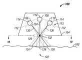
- FIG. 1Adepicts a camera array assembly 100 airborne over target 102 (e.g., terrain).
- target 102e.g., terrain
- Assembly 100comprises a housing 104 within which imaging sensors 106 , 108 , and 110 are disposed along a concave curvilinear array axis 112 , forming an array 113 .
- the radius of curvature of array axis 112may be altered dramatically, providing the ability to effect very subtle or very drastic degrees of concavity in axis 112 .
- array axis 112may be completely linear—having no curvature at all.
- Imaging sensors 106 , 108 , and 110couple to housing 104 , either directly or indirectly, by attachment members 114 .
- Attachment members 114may comprise a number of fixed or dynamic, permanent or temporary, connective apparatus.
- members 114may comprise simple welds, removable clamping devices, or electro-mechanically controlled universal joints.
- housing 104comprises a simple enclosure inside of which sensors 106 , 108 , and 110 are disposed. Sensors 106 , 108 , and 110 couple, via members 114 , either collectively to a single transverse cross member 116 , or individually to lateral cross members 118 , disposed between opposing walls of housing 104 .
- housing 104may itself comprise only a supporting cross member of concave curvature to which sensors 106 , 108 , and 110 couple, via members 114 .
- housing 104may comprise a hybrid combination of enclosure and supporting cross member.
- housing 104has an aperture 120 formed in its surface, between the sensors 106 , 108 , 110 and target 102 .
- the housing 104 structuremay be varied significantly, including being a minimal structure that is open on the lower side, such that no aperture 120 is formed.
- aperture 120may comprise only a void, or it may comprise a protective screen or window to maintain environmental integrity within housing 104 .
- aperture 120may comprise a lens or other optical device to enhance or alter the nature of the images recorded by the sensors.
- Aperture 120is formed with a size and shape sufficient to provide sensors 106 , 108 , and 110 with proper lines of sight to a target region 122 on terrain 102 .
- Sensors 106 , 108 and 110are disposed within or along housing 104 such that the focal axes of all sensors converge and intersect each other within an intersection area 132 bounded by aperture 120 . Depending upon the type of image data being collected, the specific sensors used, and other optics or equipment employed, it may be necessary or desirable to offset the intersection area 132 or point of convergence above or below aperture 120 . Sensors 106 , 108 and 110 are separated from each other at angular intervals, which are preferably equal. The exact angle of displacement between the sensors may vary widely depending upon the number of sensors utilized and on the type of imaging data being collected. In alternative embodiments, the angular displacement between sensors may be unequal—so as to provide a desired image offset or alignment.
- the focal axes 124 , 130 , 136 of all sensorsmay intersect at exactly the same point, or may intersect at a plurality of points, all within close proximity to each other and within the intersection area 132 defined by aperture 120 .
- the precise alignment necessary to yield only a single intersection point 132may be very difficult, if not impossible, to maintain. It is not necessary to maintain a single intersection point 132 , as long as all axes converge and intersect in close proximity to one another such that the size and shape of aperture 120 need not be altered to provide a proper line of sight to the sensors 106 , 108 , 110 .
- sensor 108is centrally disposed within housing 104 along array axis 112 .
- Sensor 108has a focal axis 124 , directed orthogonally from housing 104 to align the sensor's line of sight with image area 126 of region 122 .
- Sensor 106is disposed within housing 104 along array axis 112 , adjacent to sensor 108 .
- Sensor 106is aligned such that its line of sight coincides with image area 128 of region 122 , and such that its focal axis 130 converges with and intersects axis 124 at intersection point 132 .
- Sensor 110is disposed within housing 104 adjacent to sensor 108 , on the opposite side of array axis 112 from sensor 106 .
- Sensor 108is aligned such that its line of sight coincides with image area 134 of region 122 , and such that its focal axis 136 converges with and intersects axes 124 and 130 at intersection point 132 .
- Sensors 106 , 108 and 110may comprise a number of imaging devices including individual cameras, infrared sensors, seismic sensors, photo detectors and photocells. Further, the infrared sensors may be multispectral or hyperspectral. Each sensor may comprise an individual imaging device, a group of sensors. Sensors 106 , 108 and 110 are preferably of a homogenous nature, but may comprise a combination of varied imaging devices.
- sensors 106 and 110are alternately disposed within housing 104 along array axis 112 such that each sensor's focal axis converges upon point 132 , crosses focal axis 124 , and aligns its field of view with a target area opposite its respective position in the array 113 —resulting in a “cross-eyed”, retinal relationship between the sensors and the imaging target(s).
- members 114are of a permanent and fixed nature (e.g., welds), then the spatial relationship between aperture 120 , the sensors, and their lines of sight remain fixed—as will the spatial relationship between image areas 126 , 128 and 134 .
- Such a configurationmay be desirable in, for example, a satellite surveillance application where assembly 100 will remain at an essentially fixed distance from region 122 .
- the position and alignment of the sensorsis set such that areas 126 , 128 and 134 provide full imaging coverage of region 122 .
- An airborne imaging system 200is depicted, and comprises an array assembly 100 in addition to a flight control system 202 , a camera control system 204 , and an image processing system 206 .
- System 206receives imaging data from the imaging sensors within assembly 100 via communicative links 208 .
- Links 208may comprise direct, physical connectors (e.g., wires, cables) between assembly 100 and system 206 , or they may comprise communications connections (e.g., wireless transceivers).
- System 206may be located within the same host craft (e.g., airplane) as assembly 100 , or may be remotely located apart from the host craft (e.g., satellite monitoring station). Imaging data from assembly 100 is transmitted to system 206 , where it may be monitored, analyzed, processed or stored. If a change is desired in the imaging data being collected by assembly 100 , system 206 may initiate changes in the position of the host craft, assembly 100 , the individual sensors within assembly 100 , or any combination thereof.
- system 206provides notification of the desired change to flight control system 202 via communicative link 210 (e.g., change altitude).
- Link 210may comprise a direct, physical connector (e.g., wire, cable) or an indirect communications connection (e.g., wireless transceivers).
- System 202may comprise a number of collocated or remote navigation systems or combinations thereof—from a pilot onboard an aircraft to a remote flight control system on a satellite.
- Link 212may comprise a communicative link (e.g., cable, wireless transceivers) that notifies assembly 100 of the desired change (e.g., raise, lower, rotate), leaving assembly 100 to actuate the change via internal or externally associated mechanical systems (e.g., hydraulics).
- link 212may comprise a mechanical link that directly effects the desired change itself.
- Link 210may comprise a direct, physical connector (e.g., wire, cable) or an indirect communications connection (e.g., wireless transceivers).
- system 206provides notification of the desired change to camera control system 204 via communicative link 214 (e.g., change position of focal intersection point 132 ).
- Link 214may comprise a direct, physical connector (e.g., wire, cable), or an indirect communications connection (e.g., wireless transceivers).
- Individual sensors within assembly 100receive notification of desired changes (e.g., change position, change angle) via links 216 , which communicate the necessary adjustments to members 114 .
- Links 216may comprise communicative links (e.g., cables, wireless transceivers) that notify members 114 of changes desired (e.g., raise, lower, rotate), leaving members 114 to actuate the changes via internal or externally associated mechanical systems (e.g., hydraulics).
- links 216may comprise mechanical links that directly effect the desired changes.
- System 204may comprise a number of control devices and systems, disposed within assembly 100 , located externally but proximal to assembly 100 , or remote from assembly 100 , or combinations thereof.
- systems 202 , 204 , and 206may, depending upon the application and host craft or housing 104 configuration, comprise separate functionalities of a single control system deployed within the host craft.
- a computer-based, self-contained, electro-mechanical control system on board a manned surveillance aircrafte.g., a surveillance satellite
- certain elementse.g., system 202 and 204
- the host crafte.g., the satellite
- other elementse.g., system 206
- Other combinations of the systems described aboveare also comprehended by the present invention.
- FIG. 3depicts a camera array assembly 300 , comprising a housing 302 within which a plurality of imaging sensors 304 are disposed along a concave curvilinear array axis 306 .
- Assembly 300is essentially identical in composition, construction, and operation to assembly 100 , with the exception of having a greater number of imaging sensors 304 disposed therein.
- the sensors 304couple to housing 302 , either directly or indirectly, by attachment members (not shown).
- the sensors 304may couple collectively to a single transverse cross member 116 , individually to lateral cross members 118 , or directly to housing 302 .
- Housing 302comprises an aperture 308 formed in its surface, between the sensors 304 and a target below (not shown).
- aperture 308may comprise a void, a protective screen or window, or a lens or other optical device.
- Aperture 308is formed with a size and shape sufficient to provide sensors 304 proper line of sight to a target region.
- Sensors 304are disposed within or along housing 302 such that the focal axes 310 of all sensors 304 converge and intersect each other within the area defined by aperture 308 .
- the focal axes 310 of all sensors 304may intersect at exactly one intersection point 312 , or may intersect at a plurality of intersection points all within close proximity to each other and within the area defined by aperture 308 .
- the sensors 304are disposed within housing 302 along array axis 306 in a “cross-eyed” fashion.
- One sensoris centrally disposed, with focal axis 310 directed orthogonally from housing 302 .
- the other sensors 304are alternately disposed within housing 302 along axis 306 such that the focal axis 310 of each sensor 304 converges upon point 312 , crosses the focal axis of the central sensor, and aligns its field of view with a target area opposite its respective position in the array.
- the sensors 304may comprise a number of imaging devices including individual cameras, infrared sensors, seismic sensors, photo detectors and photocells—either as individual devices or as a group.
- sensors 304are all of a homogenous nature, but they may comprise a combination of varied imaging devices.
- the relative positions and angles of the sensors 304may be fixed, or may be manually or mechanically adjustable.
- the embodiments described thus farare particularly useful for collecting and processing imaging data from extremely wide, rectilinear strips.
- the rectilinear imagecan be combined with subsequent images taken along the host craft's flight path to create a composite image having an extremely large FOV.
- the present inventionprovides further embodiments that may lessen or eliminate the need for orthophotographic techniques, depending upon the application.
- FIGS. 4A and 4Bdepict a camera array assembly 400 . Except for the differences described hereafter, assembly 400 is similar in composition, construction, and operation to assemblies 100 and 300 .
- assembly 400comprises first imaging element or array 402 and second array 404 .
- Arrays 402 and 404are configured as parallel sub-arrays of imaging sensors, longitudinally offset by a desired margin.
- Array 402comprises housing 406 , within which imaging sensors 408 , 410 , 412 , and 414 are disposed in accordance with the present invention along concave curvilinear array axis 416 .
- Array 404comprises housing 418 , within which imaging sensors 420 , 422 , and 424 are disposed in accordance with the present invention along concave curvilinear array axis 426 .
- Elements 402 and 404are disposed within a host craft in close longitudinal proximity to each other, having axes 416 and 426 , preferably in parallel alignment, to collect and provide imaging data for a common target region (not shown).
- Sensors 408 , 410 , 412 , 414 , 420 , 422 , and 424are preferably similar in shape and size, but may be of differing shapes and sizes, providing the ability to retrieve an image of the target region having a desired shape or size.
- Individual sensors having specific shapes and sizescan be disposed and manipulated to focus on image areas that adjoin or overlap in desired patterns.
- sensor 422is centrally disposed within housing 418 along array axis 426 such that its focal axis is directed from housing 418 through intersection area 428 .
- Area 428is a point or small region through which the focal axes of all the imaging sensors within 418 align.
- Arrays 402 and 404may be disposed within assembly 400 such that area 428 is orthogonally centered with respect to sensor 422 , whereas the array 402 is orthogonal centered on area 429 (as depicted in FIG. 4A ).
- Sensors 420 and 424are alternately disposed within housing 418 along array axis 426 such that the focal axis of each converges upon area 428 , crosses the focal axis of sensor 422 , and aligns its field of view with a target area opposite its respective position in the array 404 .
- Sensors 410 and 412are alternately disposed within housing 406 along array axis 416 such that the focal axis of each converges upon area 429 and align their field of view with a target area opposite their respective position in the array 404 .
- Sensors 410 and 412are disposed within housing 406 such that their fields of view align with the gaps between sensors 420 , 422 , and 424 .
- Sensors 408 and 414are alternately disposed within housing 406 along array axis 416 such that the focal axis of each converges upon area 429 .
- Sensors 410 and 412are disposed within housing 406 , outside sensors 410 and 412 , such that their fields of view align outside all sensors in element 404 .
- the slight offset in the sensors of elements 402 and 404provide assembly 400 with the ability to produce images having customizable FOVs.
- any number of arrays, containing any number of sensors having various shapes and sizesmay be combined to provide imaging data on any desired target region.
- the resulting offset in images collected by the sub-arrays of assembly 400may be resolved with one another, using a variety of image processing techniques, to provide a single high-resolution image.
- FIG. 5a cross-sectional view of a camera array assembly 500 is illustrated. Except for the differences described hereafter, assembly 500 is similar in composition, construction, and operation to assemblies 100 , 300 and 400 .
- Assembly 500comprises a first compound member 502 , shown in side view, and a second compound member 504 , shown in cross-sectional view.
- Member 502comprises a curvilinear support member or array, to which a number of imaging sensors 508 are disposed along its concave side.
- a primary imaging sensor 506is centrally disposed along the concave side of member 502 , with its focal axis directed orthogonally downward from assembly 500 .
- a number of imaging sensors 508are also disposed along the concave side of member 502 , in a “cross-eyed” fashion.
- the cross-eyed sensors 508are alternately disposed along member 502 such that the focal axis of each sensor 508 converges upon and crosses the focal axis of sensor 506 at a single intersection area (not shown), and aligns its field of view with a target area opposite its respective position in the array.
- Member 504also comprises a curvilinear support member or array, to which a number of imaging sensors 510 are disposed along its concave side.
- Member 504is preferably formed orthogonal to 502 and is of a size and curvature sufficient to match the arch of member 502 .
- Member 504may be formed or disposed such that its concave surface contacts, or even couples to, the convex surface of member 502 at its apex. Alternatively, member 504 may bridge over member 502 , clearing its apex within proximal distance thereto. Imaging sensors 510 are disposed along the concave side of member 504 , in a “cross-eyed” fashion.
- the cross-eyed sensors 510are alternately disposed along member 502 such that the focal axis of each sensor 510 converges upon and crosses the focal axis of sensor 506 at the single intersection area, and aligns its field of view with a target area opposite its respective position in the array.
- assembly 500with the ability to produce images having customizable FOVs.
- assembly 500may be deployed to produce stereoscopic images.
- any number of elements, containing any number of sensors having various shapes and sizes,may be combined to provide imaging data on any desired target region.
- FIG. 6depicts a camera array assembly 600 from a bottom view.
- Assembly 600comprises a primary compound curvilinear member or array 602 , and a plurality of compound curvilinear members 604 that are formed of size and curvature sufficient to offset and arch over or contact member 602 at various angular intervals. Any number of members 604 may be employed, and may be so numerous as to form a dome structure for mounting sensors.
- the angular displacement between the members 604varies depending upon the size of the members and the desired imaging characteristics.
- assembly 600may comprise two support members in an orthogonal (i.e. 90°) relationship with one another.
- Another assembly, having three support membersmay be configured such that the angular displacement between members is 60°.
- a primary imaging sensor 606is centrally disposed along the concave side of member 602 , with its focal axis directed orthogonally downward from assembly 600 .
- a number of imaging sensors 608are disposed, in accordance with the teachings of the present invention, along the concave sides of members 602 and 604 in a “cross-eyed” fashion.
- the cross-eyed sensors 608are alternately disposed along members 602 and 604 such that the focal axis of each sensor preferably converges upon and crosses the focal axis of sensor 606 at a single intersection area (not shown), and aligns its field of view with a target area opposite its respective position in the array.
- assembly 600provides the ability to produce images having customizable FOVs, of a generally circular nature. Depending upon the elements and sensors utilized, assembly 600 may be deployed to produce stereoscopic images. In alternative embodiments, any number of elements, containing any number of sensors having various shapes and sizes, may be combined to provide imaging data on any desired target region.
- Assembly 700is similar in composition, construction, and operation to assemblies 100 , 300 and 400 .
- Assembly 700comprises first imaging element or array 702 , second imaging array 704 , and third imaging array 706 .
- Array 704is configured as a primary sensor array, disposed within assembly 700 such that the focal axis 708 of its primary sensor 710 is directed downwardly from assembly 700 , orthogonal to target area 712 along terrain 714 .
- Assembly 700is disposed within a host craft that moves, with respect to terrain 714 , along flight path 716 .
- Elements 702 , 704 and 706are configured within assembly 700 as sub-arrays of imaging sensors.
- Element 702is offset, with respect to flight path 716 , ahead of element 704 and offset there from by angular offset 718 .
- element 706is offset, with respect to flight path 716 , behind element 704 and offset there from by angular offset 720 .
- Angular offset 718is selected such that the focal axis 722 of primary sensor 724 on element 702 is directed downward to target area 712 , forming angle 732 .
- Angular offset 720is selected such that the focal axis 728 of primary sensor 730 on element 706 is directed downward to target area 712 , forming angle 726 .
- Angular offsets 718 and 720are preferably equal, although they may be skewed to provide a desired imaging effect.
- Imaging datais characterized, on a pixel-by-pixel basis, in terms of the positional and angular relationships described above.
- imaging data collected by assembly 700are processed to provide high-resolution orthographic images.
- the elements and sensorsare configured, and the data collected is processed, to provide high-resolution stereographic images.
- the size and resolution of the imaging arraymay be altered in accordance with the present as described above.
- the camera assembly 700is modified and comprises one imaging element or array 702 , configured as a primary sensor array, as described above, and having an actuator or motor (not shown) that rocks or moves the array 402 back and forth.
- the actuatormay flip or rotate the array 702 .
- the array 702is directed to forward, downward, and backward positions.
- the array 702is stationary, and a moving mirror system is used in conjunction with the mirror system to collect sensor data from multiple positions of the terrain 714 .
Landscapes
- Engineering & Computer Science (AREA)
- Multimedia (AREA)
- Signal Processing (AREA)
- Physics & Mathematics (AREA)
- General Physics & Mathematics (AREA)
- Radar, Positioning & Navigation (AREA)
- Remote Sensing (AREA)
- Studio Devices (AREA)
- Stereoscopic And Panoramic Photography (AREA)
- Eye Examination Apparatus (AREA)
- Accessories Of Cameras (AREA)
- Prostheses (AREA)
Abstract
Description
Claims (14)
Priority Applications (14)
| Application Number | Priority Date | Filing Date | Title |
|---|---|---|---|
| US10/229,626US7893957B2 (en) | 2002-08-28 | 2002-08-28 | Retinal array compound camera system |
| KR1020057003544AKR20050043925A (en) | 2002-08-28 | 2003-08-28 | Retinal array compound camera system |
| PCT/US2003/026950WO2004021692A2 (en) | 2002-08-28 | 2003-08-28 | Retinal array compound camera system |
| CA002534978ACA2534978A1 (en) | 2002-08-28 | 2003-08-28 | Retinal array compound camera system |
| AU2003262941AAU2003262941A1 (en) | 2002-08-28 | 2003-08-28 | Retinal array compound camera system |
| BR0313900-0ABR0313900A (en) | 2002-08-28 | 2003-08-28 | Retinal Array Camera System |
| EP03791891AEP1543678A4 (en) | 2002-08-28 | 2003-08-28 | Retinal array compound camera system |
| EA200500412AEA007248B1 (en) | 2002-08-28 | 2003-08-28 | Retinal array compound camera system |
| JP2004531627AJP2005538394A (en) | 2002-08-28 | 2003-08-28 | Compound camera system arranged in retinal form |
| CNA038204630ACN1679337A (en) | 2002-08-28 | 2003-08-28 | Retinal array compound camera system |
| US11/805,109US8334903B2 (en) | 2002-08-28 | 2007-05-22 | Retinal array compound camera system having at least three imaging sensors |
| US12/462,533US8896695B2 (en) | 2002-08-28 | 2009-08-05 | Retinal concave array compound camera system |
| US12/583,815US8471907B2 (en) | 2002-08-28 | 2009-08-26 | Method of producing a remote imaging array |
| US13/590,735US8994822B2 (en) | 2002-08-28 | 2012-08-21 | Infrastructure mapping system and method |
Applications Claiming Priority (1)
| Application Number | Priority Date | Filing Date | Title |
|---|---|---|---|
| US10/229,626US7893957B2 (en) | 2002-08-28 | 2002-08-28 | Retinal array compound camera system |
Related Parent Applications (1)
| Application Number | Title | Priority Date | Filing Date |
|---|---|---|---|
| US12/798,899Continuation-In-PartUS8483960B2 (en) | 2002-08-28 | 2010-04-13 | Self-calibrated, remote imaging and data processing system |
Related Child Applications (3)
| Application Number | Title | Priority Date | Filing Date |
|---|---|---|---|
| US11/805,109DivisionUS8334903B2 (en) | 2002-08-28 | 2007-05-22 | Retinal array compound camera system having at least three imaging sensors |
| US12/462,533DivisionUS8896695B2 (en) | 2002-08-28 | 2009-08-05 | Retinal concave array compound camera system |
| US12/583,815DivisionUS8471907B2 (en) | 2002-08-28 | 2009-08-26 | Method of producing a remote imaging array |
Publications (2)
| Publication Number | Publication Date |
|---|---|
| US20040041914A1 US20040041914A1 (en) | 2004-03-04 |
| US7893957B2true US7893957B2 (en) | 2011-02-22 |
Family
ID=31976277
Family Applications (4)
| Application Number | Title | Priority Date | Filing Date |
|---|---|---|---|
| US10/229,626Expired - LifetimeUS7893957B2 (en) | 2002-08-28 | 2002-08-28 | Retinal array compound camera system |
| US11/805,109Expired - Fee RelatedUS8334903B2 (en) | 2002-08-28 | 2007-05-22 | Retinal array compound camera system having at least three imaging sensors |
| US12/462,533Active2026-01-20US8896695B2 (en) | 2002-08-28 | 2009-08-05 | Retinal concave array compound camera system |
| US12/583,815Expired - Fee RelatedUS8471907B2 (en) | 2002-08-28 | 2009-08-26 | Method of producing a remote imaging array |
Family Applications After (3)
| Application Number | Title | Priority Date | Filing Date |
|---|---|---|---|
| US11/805,109Expired - Fee RelatedUS8334903B2 (en) | 2002-08-28 | 2007-05-22 | Retinal array compound camera system having at least three imaging sensors |
| US12/462,533Active2026-01-20US8896695B2 (en) | 2002-08-28 | 2009-08-05 | Retinal concave array compound camera system |
| US12/583,815Expired - Fee RelatedUS8471907B2 (en) | 2002-08-28 | 2009-08-26 | Method of producing a remote imaging array |
Country Status (10)
| Country | Link |
|---|---|
| US (4) | US7893957B2 (en) |
| EP (1) | EP1543678A4 (en) |
| JP (1) | JP2005538394A (en) |
| KR (1) | KR20050043925A (en) |
| CN (1) | CN1679337A (en) |
| AU (1) | AU2003262941A1 (en) |
| BR (1) | BR0313900A (en) |
| CA (1) | CA2534978A1 (en) |
| EA (1) | EA007248B1 (en) |
| WO (1) | WO2004021692A2 (en) |
Cited By (23)
| Publication number | Priority date | Publication date | Assignee | Title |
|---|---|---|---|---|
| US20120075427A1 (en)* | 2010-09-24 | 2012-03-29 | Microsoft Corporation | Wide angle field of view active illumination imaging system |
| WO2013033495A1 (en)* | 2011-08-31 | 2013-03-07 | Cablecam, Llc. | Aerial movement system having multiple payloads |
| US9294672B2 (en) | 2014-06-20 | 2016-03-22 | Qualcomm Incorporated | Multi-camera system using folded optics free from parallax and tilt artifacts |
| US9337949B2 (en) | 2011-08-31 | 2016-05-10 | Cablecam, Llc | Control system for an aerially moved payload |
| US9374516B2 (en) | 2014-04-04 | 2016-06-21 | Qualcomm Incorporated | Auto-focus in low-profile folded optics multi-camera system |
| US9383550B2 (en) | 2014-04-04 | 2016-07-05 | Qualcomm Incorporated | Auto-focus in low-profile folded optics multi-camera system |
| US9386222B2 (en) | 2014-06-20 | 2016-07-05 | Qualcomm Incorporated | Multi-camera system using folded optics free from parallax artifacts |
| US9398264B2 (en) | 2012-10-19 | 2016-07-19 | Qualcomm Incorporated | Multi-camera system using folded optics |
| US9438889B2 (en) | 2011-09-21 | 2016-09-06 | Qualcomm Incorporated | System and method for improving methods of manufacturing stereoscopic image sensors |
| US9440750B2 (en)* | 2014-06-20 | 2016-09-13 | nearmap australia pty ltd. | Wide-area aerial camera systems |
| US9477141B2 (en) | 2011-08-31 | 2016-10-25 | Cablecam, Llc | Aerial movement system having multiple payloads |
| US9485495B2 (en) | 2010-08-09 | 2016-11-01 | Qualcomm Incorporated | Autofocus for stereo images |
| US9541740B2 (en) | 2014-06-20 | 2017-01-10 | Qualcomm Incorporated | Folded optic array camera using refractive prisms |
| US9549107B2 (en) | 2014-06-20 | 2017-01-17 | Qualcomm Incorporated | Autofocus for folded optic array cameras |
| US20170195569A1 (en)* | 2014-06-20 | 2017-07-06 | nearmap australia pty ltd. | Wide-area aerial camera systems |
| US9819863B2 (en) | 2014-06-20 | 2017-11-14 | Qualcomm Incorporated | Wide field of view array camera for hemispheric and spherical imaging |
| US9832381B2 (en) | 2014-10-31 | 2017-11-28 | Qualcomm Incorporated | Optical image stabilization for thin cameras |
| US10013764B2 (en) | 2014-06-19 | 2018-07-03 | Qualcomm Incorporated | Local adaptive histogram equalization |
| US10178373B2 (en) | 2013-08-16 | 2019-01-08 | Qualcomm Incorporated | Stereo yaw correction using autofocus feedback |
| US10684362B2 (en) | 2011-06-30 | 2020-06-16 | The Regents Of The University Of Colorado | Remote measurement of shallow depths in semi-transparent media |
| US11231502B2 (en) | 2011-06-30 | 2022-01-25 | The Regents Of The University Of Colorado | Remote measurement of shallow depths in semi-transparent media |
| US11313678B2 (en) | 2011-06-30 | 2022-04-26 | The Regents Of The University Of Colorado | Remote measurement of shallow depths in semi-transparent media |
| US11933899B2 (en) | 2011-06-30 | 2024-03-19 | The Regents Of The University Of Colorado | Remote measurement of shallow depths in semi-transparent media |
Families Citing this family (43)
| Publication number | Priority date | Publication date | Assignee | Title |
|---|---|---|---|---|
| US7893957B2 (en) | 2002-08-28 | 2011-02-22 | Visual Intelligence, LP | Retinal array compound camera system |
| US8483960B2 (en) | 2002-09-20 | 2013-07-09 | Visual Intelligence, LP | Self-calibrated, remote imaging and data processing system |
| US8994822B2 (en) | 2002-08-28 | 2015-03-31 | Visual Intelligence Lp | Infrastructure mapping system and method |
| USRE49105E1 (en) | 2002-09-20 | 2022-06-14 | Vi Technologies, Llc | Self-calibrated, remote imaging and data processing system |
| TW200634801A (en)* | 2004-11-17 | 2006-10-01 | Hitachi Maxell | Optical information-recording medium |
| JP2006203448A (en)* | 2005-01-19 | 2006-08-03 | Hitachi Ltd | In-vehicle stereo camera device |
| US9182228B2 (en)* | 2006-02-13 | 2015-11-10 | Sony Corporation | Multi-lens array system and method |
| US7773121B1 (en)* | 2006-05-03 | 2010-08-10 | The United States Of America As Represented By The Administrator Of The National Aeronautics And Space Administration | High-resolution, continuous field-of-view (FOV), non-rotating imaging system |
| US20080084478A1 (en)* | 2006-09-28 | 2008-04-10 | Zvika Gilad | System and method for an in-vivo imaging device with an angled field of view |
| US20080100711A1 (en)* | 2006-10-26 | 2008-05-01 | Wisted Jeffrey M | Integrated Multiple Imaging Device |
| US7742090B2 (en)* | 2006-12-22 | 2010-06-22 | Palo Alto Research Center Incorporated | Flexible segmented image sensor |
| US20150189140A1 (en)* | 2009-02-23 | 2015-07-02 | Gary Edwin Sutton | Curved sensor array camera |
| WO2010134502A1 (en)* | 2009-05-18 | 2010-11-25 | 小平アソシエイツ株式会社 | Image information output method |
| CA2796162A1 (en)* | 2010-04-13 | 2012-10-04 | Visual Intelligence, LP | Self-calibrated, remote imaging and data processing system |
| CN101825840A (en)* | 2010-05-06 | 2010-09-08 | 浙江大学 | Multi-camera real-time omnidirectional imaging system |
| CN102170571A (en)* | 2010-06-22 | 2011-08-31 | 上海盈方微电子有限公司 | Digital still camera framework for supporting two-channel CMOS (Complementary Metal Oxide Semiconductor) sensor |
| US20120056987A1 (en)* | 2010-09-03 | 2012-03-08 | Luke Fedoroff | 3d camera system and method |
| US9118833B2 (en)* | 2010-11-29 | 2015-08-25 | Fotonation Limited | Portrait image synthesis from multiple images captured on a handheld device |
| US9007432B2 (en) | 2010-12-16 | 2015-04-14 | The Massachusetts Institute Of Technology | Imaging systems and methods for immersive surveillance |
| US9036001B2 (en) | 2010-12-16 | 2015-05-19 | Massachusetts Institute Of Technology | Imaging system for immersive surveillance |
| JP2014511155A (en)* | 2011-03-31 | 2014-05-12 | ビジュアル インテリジェンス,エルピー | Self-calibrating remote imaging and data processing system |
| GB2494850B (en)* | 2011-04-21 | 2013-09-11 | Cp Electronics Ltd | Passive infra red detector |
| JP6282275B2 (en)* | 2012-08-21 | 2018-03-07 | ビジュアル インテリジェンス, エルピーVisual Intelligence, Lp | Infrastructure mapping system and method |
| RU2518365C1 (en)* | 2012-11-22 | 2014-06-10 | Александр Николаевич Барышников | Optical-electronic photodetector (versions) |
| CN104580869B (en)* | 2013-10-10 | 2018-06-05 | 华为技术有限公司 | A kind of light-field camera |
| US9733344B2 (en)* | 2013-11-25 | 2017-08-15 | Electronics And Telecommunications Research Institute | Laser radar apparatus and method for operating thereof |
| DE102013226789B4 (en)* | 2013-12-19 | 2017-02-09 | Fraunhofer-Gesellschaft zur Förderung der angewandten Forschung e.V. | Multi-channel optical image pickup device and multi-channel optical image pickup method |
| US9262801B2 (en)* | 2014-04-01 | 2016-02-16 | Gopro, Inc. | Image taping in a multi-camera array |
| EP3026652A1 (en)* | 2014-11-27 | 2016-06-01 | Kapsch TrafficCom AB | Double stereoscopic sensor |
| WO2016119065A1 (en)* | 2015-01-29 | 2016-08-04 | Rocky Mountain Equipment Canada Ltd. | Uav navigation and sensor system configuration |
| US10012723B2 (en)* | 2015-03-31 | 2018-07-03 | Amazon Technologies, Inc. | Modular LIDAR system |
| GB2544970B (en)* | 2015-11-27 | 2018-01-24 | Sony Interactive Entertainment Inc | Image capture apparatus |
| JP7334881B2 (en)* | 2017-05-10 | 2023-08-29 | モービルアイ ビジョン テクノロジーズ リミテッド | Cross-field of view for autonomous vehicle systems |
| DE102017114962B4 (en) | 2017-07-05 | 2019-08-29 | Dallmeier Electronic Gmbh & Co. Kg | Multi-sensor camera |
| EP3857867A4 (en)* | 2018-09-28 | 2022-09-14 | Brainbaby Inc | Self-contained low profile cross shooting video apparatus |
| US10956694B2 (en) | 2019-04-05 | 2021-03-23 | Zebra Technologies Corporation | Device and method for data capture aiming assistance |
| US11592598B1 (en)* | 2019-05-20 | 2023-02-28 | Perry J. Sheppard | Virtual lens optical system |
| CN110296689B (en)* | 2019-05-31 | 2020-06-26 | 中国科学院西安光学精密机械研究所 | A device and method for testing the overlap ratio of swept images in an aerial imaging camera |
| US11394955B2 (en)* | 2020-01-17 | 2022-07-19 | Aptiv Technologies Limited | Optics device for testing cameras useful on vehicles |
| DE102020125064A1 (en) | 2020-09-25 | 2022-03-31 | Trioptics Gmbh | MTF test device and its use |
| WO2023149963A1 (en) | 2022-02-01 | 2023-08-10 | Landscan Llc | Systems and methods for multispectral landscape mapping |
| US12366447B2 (en)* | 2022-03-07 | 2025-07-22 | Stuart NIXON | Airborne and spaceborne imaging survey platform |
| IL310995A (en)* | 2024-02-21 | 2025-09-01 | Israel Aerospace Ind Ltd | Improved imaging platform |
Citations (39)
| Publication number | Priority date | Publication date | Assignee | Title |
|---|---|---|---|---|
| US1699136A (en) | 1929-01-15 | eliel | ||
| US2104976A (en) | 1936-02-29 | 1938-01-11 | Leon T Eliel | Apparatus for aerial photography |
| US2433534A (en) | 1944-04-14 | 1947-12-30 | Chicago Aerial Survey Company | Stereoscopic camera |
| US2747012A (en) | 1953-04-10 | 1956-05-22 | Vitarama Corp | Closed link electronic camera chain |
| US2955518A (en) | 1958-07-03 | 1960-10-11 | Texas Instruments Inc | Aerial camera |
| US3518929A (en) | 1967-03-06 | 1970-07-07 | Gen Electric | Three dimensional camera |
| US4322741A (en) | 1980-08-26 | 1982-03-30 | Jun Kawabayashi | Image dividing system for use in television |
| US4504914A (en) | 1980-11-19 | 1985-03-12 | Messerschmitt-Bolkow-Blohm Gesellschaft Mit Beschrankter Haftung | Photogrammetric device for aircraft and spacecraft for producing a digital terrain representation |
| US4650305A (en) | 1985-12-19 | 1987-03-17 | Hineslab | Camera mounting apparatus |
| US4689748A (en) | 1979-10-09 | 1987-08-25 | Messerschmitt-Bolkow-Blohm Gesellschaft Mit Beschrankter Haftung | Device for aircraft and spacecraft for producing a digital terrain representation |
| US4708472A (en) | 1982-05-19 | 1987-11-24 | Messerschmitt-Bolkow-Blohm Gmbh | Stereophotogrammetric surveying and evaluation method |
| US4724449A (en) | 1986-03-25 | 1988-02-09 | Douglas Wright | Method and apparatus for stereoscopic photography |
| US4750810A (en) | 1985-11-08 | 1988-06-14 | British Telecommunications Plc | Camera optics for producing a composite image from two scenes |
| US4757378A (en) | 1986-09-30 | 1988-07-12 | The Boeing Company | Monocular scene generator for biocular wide field of view display system |
| US4764008A (en)* | 1987-11-19 | 1988-08-16 | Wren Clifford T | Surveillance housing assembly |
| US4887779A (en)* | 1987-12-01 | 1989-12-19 | The Boeing Company | Roll drum sensor housing having sliding window |
| US4956705A (en) | 1989-03-10 | 1990-09-11 | Dimensional Visions Group | Electronic method and apparatus for stereoscopic photography |
| US5027199A (en)* | 1988-09-20 | 1991-06-25 | Nec Corporation | Image pickup system capable of obtaining a plurality of stereo images with different base height ratios |
| US5029009A (en) | 1989-05-08 | 1991-07-02 | Kaman Aerospace Corporation | Imaging camera with adaptive range gating |
| US5104217A (en) | 1986-03-17 | 1992-04-14 | Geospectra Corporation | System for determining and controlling the attitude of a moving airborne or spaceborne platform or the like |
| US5138444A (en) | 1991-09-05 | 1992-08-11 | Nec Corporation | Image pickup system capable of producing correct image signals of an object zone |
| US5193124A (en) | 1989-06-29 | 1993-03-09 | The Research Foundation Of State University Of New York | Computational methods and electronic camera apparatus for determining distance of objects, rapid autofocusing, and obtaining improved focus images |
| US5249034A (en)* | 1991-01-29 | 1993-09-28 | Toyo Glass Co., Ltd. | Method of and apparatus for inspecting end of object for defect |
| US5276321A (en) | 1991-04-15 | 1994-01-04 | Geophysical & Environmental Research Corp. | Airborne multiband imaging spectrometer |
| US5426476A (en)* | 1994-11-16 | 1995-06-20 | Fussell; James C. | Aircraft video camera mount |
| US5471056A (en) | 1992-09-25 | 1995-11-28 | Texaco Inc. | Airborne scanner image spectrometer |
| US5721611A (en) | 1993-02-15 | 1998-02-24 | E.M.S. Technik, Gmbh | Photogrammetric camera, in particular for photogrammetric measurements of technical objects |
| US5734507A (en) | 1993-11-29 | 1998-03-31 | Hadland Photonics Limited | Optical beam splitter and electronic high speed camera incorporating such a beam splitter |
| US5815314A (en)* | 1993-12-27 | 1998-09-29 | Canon Kabushiki Kaisha | Image display apparatus and image display method |
| US5872590A (en)* | 1996-11-11 | 1999-02-16 | Fujitsu Ltd. | Image display apparatus and method for allowing stereoscopic video image to be observed |
| US5894323A (en) | 1996-03-22 | 1999-04-13 | Tasc, Inc, | Airborne imaging system using global positioning system (GPS) and inertial measurement unit (IMU) data |
| US6002815A (en)* | 1997-07-16 | 1999-12-14 | Kinetic Sciences, Inc. | Linear sensor imaging method and apparatus |
| US6055012A (en)* | 1995-12-29 | 2000-04-25 | Lucent Technologies Inc. | Digital multi-view video compression with complexity and compatibility constraints |
| US6422508B1 (en) | 2000-04-05 | 2002-07-23 | Galileo Group, Inc. | System for robotic control of imaging data having a steerable gimbal mounted spectral sensor and methods |
| US6473119B1 (en)* | 1997-04-08 | 2002-10-29 | Carl-Zeiss-Stiftung | Photogrammetic camera |
| US6747686B1 (en) | 2001-10-05 | 2004-06-08 | Recon/Optical, Inc. | High aspect stereoscopic mode camera and method |
| US6834163B2 (en) | 2000-07-14 | 2004-12-21 | Z/I Imaging Gmbh | Camera system having at least two first cameras and two second cameras |
| US6954310B2 (en) | 2003-09-25 | 2005-10-11 | University Of Florida Research Foundation, Inc. | High resolution multi-lens imaging device |
| US7006709B2 (en) | 2002-06-15 | 2006-02-28 | Microsoft Corporation | System and method deghosting mosaics using multiperspective plane sweep |
Family Cites Families (113)
| Publication number | Priority date | Publication date | Assignee | Title |
|---|---|---|---|---|
| US1910425A (en)* | 1928-07-26 | 1933-05-23 | Brock & Weymouth Inc | Method of making maps |
| US2036062A (en)* | 1935-07-19 | 1936-03-31 | Fairchild Aerial Camera Corp | Camera positioning device |
| US2720029A (en) | 1952-09-22 | 1955-10-11 | Fairchild Aerial Surveys Inc | Photogrammetric apparatus |
| US2896501A (en)* | 1953-05-28 | 1959-07-28 | Faximile Inc | Apparatus for outlining contours |
| US2988953A (en)* | 1957-11-29 | 1961-06-20 | Photographic Analysis Inc | Apparatus for contour plotting |
| US3109057A (en) | 1960-12-08 | 1963-10-29 | Singer Inc H R B | Stereo scanning unit and system |
| US3527880A (en)* | 1967-01-25 | 1970-09-08 | Mc Donnell Douglas Corp | Pseudo stereo-optical observation means |
| US4217607A (en)* | 1974-05-07 | 1980-08-12 | Societe Anonyme De Telecommunications | Process and device for the instantaneous display of a countryside scanned by a camera of the single line scanning type |
| DE2811428A1 (en) | 1978-03-16 | 1979-09-20 | Bosch Gmbh Robert | Headlights unit for motor vehicle - has moulded plastics vibration damping sealing ring between lens and body |
| US4398195A (en)* | 1979-07-02 | 1983-08-09 | Del Norte Technology, Inc. | Method of and apparatus for guiding agricultural aircraft |
| US4313678A (en) | 1979-09-24 | 1982-02-02 | The United States Of America As Represented By The Secretary Of The Interior | Automated satellite mapping system (MAPSAT) |
| US6204799B1 (en)* | 1980-05-27 | 2001-03-20 | William J. Caputi, Jr. | Three dimensional bistatic imaging radar processing for independent transmitter and receiver flightpaths |
| US4699748A (en)* | 1982-08-03 | 1987-10-13 | Automatic Liquid Packaging, Inc. | Container with insert having a fully or partially encapsulating seal with a frangible web formed against said insert |
| US4583703A (en)* | 1982-03-17 | 1986-04-22 | The United States Of America As Represented By The Secretary Of The Army | One fin orientation and stabilization device |
| US5308022A (en)* | 1982-04-30 | 1994-05-03 | Cubic Corporation | Method of generating a dynamic display of an aircraft from the viewpoint of a pseudo chase aircraft |
| FR2536851B1 (en)* | 1982-11-30 | 1985-06-14 | Aerospatiale | RECOGNITION SYSTEM COMPRISING AN AIR VEHICLE TURNING AROUND ITS LONGITUDINAL AXIS |
| US4814711A (en)* | 1984-04-05 | 1989-03-21 | Deseret Research, Inc. | Survey system and method for real time collection and processing of geophysicals data using signals from a global positioning satellite network |
| US4686474A (en)* | 1984-04-05 | 1987-08-11 | Deseret Research, Inc. | Survey system for collection and real time processing of geophysical data |
| US4712010A (en) | 1986-01-30 | 1987-12-08 | Hughes Aircraft Company | Radiator scanning with image enhancement and noise reduction |
| US4754327A (en)* | 1987-03-20 | 1988-06-28 | Honeywell, Inc. | Single sensor three dimensional imaging |
| US4767008A (en)* | 1987-11-02 | 1988-08-30 | Warnecke Armand E | Injection monitor appliance |
| DE3802219A1 (en)* | 1988-01-26 | 1989-08-03 | Deutsche Forsch Luft Raumfahrt | METHOD AND DEVICE FOR REMOTE DETECTION OF THE EARTH |
| US4965572A (en) | 1988-06-10 | 1990-10-23 | Turbulence Prediction Systems | Method for producing a warning of the existence of low-level wind shear and aircraftborne system for performing same |
| US5013917A (en)* | 1988-07-07 | 1991-05-07 | Kaman Aerospace Corporation | Imaging lidar system using non-visible light |
| US4935629A (en)* | 1988-10-24 | 1990-06-19 | Honeywell Inc. | Detector array for high V/H infrared linescanners |
| US5045937A (en) | 1989-08-25 | 1991-09-03 | Space Island Products & Services, Inc. | Geographical surveying using multiple cameras to obtain split-screen images with overlaid geographical coordinates |
| US5166789A (en) | 1989-08-25 | 1992-11-24 | Space Island Products & Services, Inc. | Geographical surveying using cameras in combination with flight computers to obtain images with overlaid geographical coordinates |
| IL91659A (en) | 1989-09-15 | 1995-05-26 | Israel Min Of Energy & Inf | Geophysical survey system |
| US4964721A (en) | 1989-10-12 | 1990-10-23 | Kaman Aerospace Corporation | Imaging lidar system |
| FR2653918B1 (en) | 1989-10-31 | 1992-02-14 | Europ Agence Spatiale | METHOD FOR REAL-TIME RECTIFICATION OF IMAGES OF GEOSTATIONARY METEOROLOGICAL SATELLITES. |
| US5231401A (en)* | 1990-08-10 | 1993-07-27 | Kaman Aerospace Corporation | Imaging lidar system |
| US5259037A (en) | 1991-02-07 | 1993-11-02 | Hughes Training, Inc. | Automated video imagery database generation using photogrammetry |
| US5214637A (en) | 1991-04-15 | 1993-05-25 | Codex Corporation | High speed two wire modem |
| US5371358A (en) | 1991-04-15 | 1994-12-06 | Geophysical & Environmental Research Corp. | Method and apparatus for radiometric calibration of airborne multiband imaging spectrometer |
| US5257085A (en) | 1991-04-24 | 1993-10-26 | Kaman Aerospace Corporation | Spectrally dispersive imaging lidar system |
| US5555018A (en)* | 1991-04-25 | 1996-09-10 | Von Braun; Heiko S. | Large-scale mapping of parameters of multi-dimensional structures in natural environments |
| US5187754A (en)* | 1991-04-30 | 1993-02-16 | General Electric Company | Forming, with the aid of an overview image, a composite image from a mosaic of images |
| US5457639A (en) | 1991-10-11 | 1995-10-10 | Kaman Aerospace Corporation | Imaging lidar system for shallow and coastal water |
| US5198657A (en)* | 1992-02-05 | 1993-03-30 | General Atomics | Integrated imaging and ranging lidar receiver |
| US5247356A (en) | 1992-02-14 | 1993-09-21 | Ciampa John A | Method and apparatus for mapping and measuring land |
| US5332968A (en)* | 1992-04-21 | 1994-07-26 | University Of South Florida | Magnetic resonance imaging color composites |
| US5317394A (en)* | 1992-04-30 | 1994-05-31 | Westinghouse Electric Corp. | Distributed aperture imaging and tracking system |
| US5379065A (en)* | 1992-06-22 | 1995-01-03 | The United States Of America As Represented By The Administrator Of The National Aeronautics And Space Administration | Programmable hyperspectral image mapper with on-array processing |
| FR2696843B1 (en)* | 1992-10-14 | 1994-12-09 | Matra Sep Imagerie Inf | High resolution remote camera for aerial carrier. |
| US5414462A (en)* | 1993-02-11 | 1995-05-09 | Veatch; John W. | Method and apparatus for generating a comprehensive survey map |
| JPH0728400A (en) | 1993-06-25 | 1995-01-31 | Dainippon Printing Co Ltd | Map display |
| US5517419A (en)* | 1993-07-22 | 1996-05-14 | Synectics Corporation | Advanced terrain mapping system |
| JP2807622B2 (en)* | 1993-12-13 | 1998-10-08 | 株式会社コア | Aircraft integrated photography system |
| US5467271A (en)* | 1993-12-17 | 1995-11-14 | Trw, Inc. | Mapping and analysis system for precision farming applications |
| AU690693B2 (en)* | 1994-05-19 | 1998-04-30 | Geospan Corporation | Method for collecting and processing visual and spatial position information |
| JP3490774B2 (en) | 1994-07-11 | 2004-01-26 | 三菱プレシジョン株式会社 | How to generate geospecific textures |
| US5448936A (en) | 1994-08-23 | 1995-09-12 | Hughes Aircraft Company | Destruction of underwater objects |
| US5557397A (en) | 1994-09-21 | 1996-09-17 | Airborne Remote Mapping, Inc. | Aircraft-based topographical data collection and processing system |
| US5639964A (en)* | 1994-10-24 | 1997-06-17 | Djorup; Robert S. | Thermal anemometer airstream turbulent energy detector |
| US5649032A (en)* | 1994-11-14 | 1997-07-15 | David Sarnoff Research Center, Inc. | System for automatically aligning images to form a mosaic image |
| US5596494A (en)* | 1994-11-14 | 1997-01-21 | Kuo; Shihjong | Method and apparatus for acquiring digital maps |
| US5604534A (en)* | 1995-05-24 | 1997-02-18 | Omni Solutions International, Ltd. | Direct digital airborne panoramic camera system and method |
| US5668593A (en)* | 1995-06-07 | 1997-09-16 | Recon/Optical, Inc. | Method and camera system for step frame reconnaissance with motion compensation |
| JP3488319B2 (en) | 1995-06-08 | 2004-01-19 | 三菱電機株式会社 | Driving support device for vehicles |
| US5878356A (en)* | 1995-06-14 | 1999-03-02 | Agrometrics, Inc. | Aircraft based infrared mapping system for earth based resources |
| US5963664A (en) | 1995-06-22 | 1999-10-05 | Sarnoff Corporation | Method and system for image combination using a parallax-based technique |
| US6211906B1 (en)* | 1995-09-07 | 2001-04-03 | Flight Landata, Inc. | Computerized component variable interference filter imaging spectrometer system method and apparatus |
| US5790188A (en)* | 1995-09-07 | 1998-08-04 | Flight Landata, Inc. | Computer controlled, 3-CCD camera, airborne, variable interference filter imaging spectrometer system |
| US5982951A (en) | 1996-05-28 | 1999-11-09 | Canon Kabushiki Kaisha | Apparatus and method for combining a plurality of images |
| US5953054A (en) | 1996-05-31 | 1999-09-14 | Geo-3D Inc. | Method and system for producing stereoscopic 3-dimensional images |
| US6075905A (en)* | 1996-07-17 | 2000-06-13 | Sarnoff Corporation | Method and apparatus for mosaic image construction |
| JPH10178564A (en) | 1996-10-17 | 1998-06-30 | Sharp Corp | Panoramic image creation device and recording medium |
| US6173087B1 (en)* | 1996-11-13 | 2001-01-09 | Sarnoff Corporation | Multi-view image registration with application to mosaicing and lens distortion correction |
| US5937212A (en)* | 1996-11-15 | 1999-08-10 | Canon Kabushiki Kaisha | Image pickup apparatus |
| US6597818B2 (en)* | 1997-05-09 | 2003-07-22 | Sarnoff Corporation | Method and apparatus for performing geo-spatial registration of imagery |
| US6078701A (en)* | 1997-08-01 | 2000-06-20 | Sarnoff Corporation | Method and apparatus for performing local to global multiframe alignment to construct mosaic images |
| WO1999018732A1 (en) | 1997-10-06 | 1999-04-15 | Ciampa John A | Digital-image mapping |
| US6434280B1 (en)* | 1997-11-10 | 2002-08-13 | Gentech Corporation | System and method for generating super-resolution-enhanced mosaic images |
| JPH11184375A (en) | 1997-12-25 | 1999-07-09 | Toyota Motor Corp | Digital map data processing device and digital map data processing method |
| US7006132B2 (en)* | 1998-02-25 | 2006-02-28 | California Institute Of Technology | Aperture coded camera for three dimensional imaging |
| US6281970B1 (en)* | 1998-03-12 | 2001-08-28 | Synergistix Llc | Airborne IR fire surveillance system providing firespot geopositioning |
| US6087984A (en)* | 1998-05-04 | 2000-07-11 | Trimble Navigation Limited | GPS guidance system for use with circular cultivated agricultural fields |
| US6323858B1 (en) | 1998-05-13 | 2001-11-27 | Imove Inc. | System for digitally capturing and recording panoramic movies |
| US6125329A (en)* | 1998-06-17 | 2000-09-26 | Earth Satellite Corporation | Method, system and programmed medium for massive geodetic block triangulation in satellite imaging |
| US6130705A (en) | 1998-07-10 | 2000-10-10 | Recon/Optical, Inc. | Autonomous electro-optical framing camera system with constant ground resolution, unmanned airborne vehicle therefor, and methods of use |
| US6570612B1 (en)* | 1998-09-21 | 2003-05-27 | Bank One, Na, As Administrative Agent | System and method for color normalization of board images |
| US6611289B1 (en)* | 1999-01-15 | 2003-08-26 | Yanbin Yu | Digital cameras using multiple sensors with multiple lenses |
| US6282301B1 (en)* | 1999-04-08 | 2001-08-28 | The United States Of America As Represented By The Secretary Of The Army | Ares method of sub-pixel target detection |
| US6456938B1 (en)* | 1999-07-23 | 2002-09-24 | Kent Deon Barnard | Personal dGPS golf course cartographer, navigator and internet web site with map exchange and tutor |
| CA2400975C (en)* | 2000-03-16 | 2008-11-04 | The Johns Hopkins University | Light detection and ranging (lidar) mapping system |
| US7019777B2 (en)* | 2000-04-21 | 2006-03-28 | Flight Landata, Inc. | Multispectral imaging system with spatial resolution enhancement |
| US7184072B1 (en)* | 2000-06-15 | 2007-02-27 | Power View Company, L.L.C. | Airborne inventory and inspection system and apparatus |
| US6664529B2 (en)* | 2000-07-19 | 2003-12-16 | Utah State University | 3D multispectral lidar |
| EP1178283A1 (en) | 2000-07-31 | 2002-02-06 | CO.RI.AL. Consorzio Ricerche Alimentari S.C.p.A. | Airborne spectroscopic digital camera imaging system |
| US6477326B1 (en) | 2000-08-31 | 2002-11-05 | Recon/Optical, Inc. | Dual band framing reconnaissance camera |
| GB2368219A (en) | 2000-09-13 | 2002-04-24 | Roke Manor Research | Camera system with GPS |
| US6553311B2 (en)* | 2000-12-08 | 2003-04-22 | Trimble Navigation Limited | Navigational off- line and off-heading indication system and method |
| US6707464B2 (en)* | 2001-01-31 | 2004-03-16 | Harris Corporation | System and method for identifying tie point collections used in imagery |
| AUPR301601A0 (en) | 2001-02-09 | 2001-03-08 | Commonwealth Scientific And Industrial Research Organisation | Lidar system and method |
| US6597991B1 (en)* | 2001-03-28 | 2003-07-22 | Agrosense Ltd. | System and method for remote monitoring of water stress status of growing crops |
| US6542831B1 (en)* | 2001-04-18 | 2003-04-01 | Desert Research Institute | Vehicle particulate sensor system |
| US7009638B2 (en)* | 2001-05-04 | 2006-03-07 | Vexcel Imaging Gmbh | Self-calibrating, digital, large format camera with single or multiple detector arrays and single or multiple optical systems |
| US20030210336A1 (en) | 2001-05-09 | 2003-11-13 | Sal Khan | Secure access camera and method for camera control |
| US20030048357A1 (en)* | 2001-08-29 | 2003-03-13 | Geovantage, Inc. | Digital imaging system for airborne applications |
| US6987877B2 (en)* | 2001-10-30 | 2006-01-17 | Itt Manufacturing Enterprises, Inc. | Superimposing graphic representations of ground locations onto ground location images after detection of failures |
| US6864892B2 (en) | 2002-03-08 | 2005-03-08 | Sun Microsystems, Inc. | Graphics data synchronization with multiple data paths in a graphics accelerator |
| US6781707B2 (en)* | 2002-03-22 | 2004-08-24 | Orasee Corp. | Multi-spectral display |
| US6771208B2 (en)* | 2002-04-24 | 2004-08-03 | Medius, Inc. | Multi-sensor system |
| CA2386651A1 (en)* | 2002-05-16 | 2003-11-16 | Dan Keith Andersen | Method of monitoring utility lines with aircraft |
| US7725258B2 (en)* | 2002-09-20 | 2010-05-25 | M7 Visual Intelligence, L.P. | Vehicle based data collection and processing system and imaging sensor system and methods thereof |
| US8483960B2 (en) | 2002-09-20 | 2013-07-09 | Visual Intelligence, LP | Self-calibrated, remote imaging and data processing system |
| US7893957B2 (en) | 2002-08-28 | 2011-02-22 | Visual Intelligence, LP | Retinal array compound camera system |
| EP1540937A4 (en)* | 2002-09-20 | 2008-11-12 | M7 Visual Intelligence Lp | Vehicule based data collection and porcessing system |
| US7424133B2 (en)* | 2002-11-08 | 2008-09-09 | Pictometry International Corporation | Method and apparatus for capturing, geolocating and measuring oblique images |
| US7365774B2 (en)* | 2002-12-13 | 2008-04-29 | Pierre Louis | Device with camera modules and flying apparatus provided with such a device |
| DE10341822A1 (en) | 2003-09-09 | 2005-09-29 | Clauß, Ulrich, Dr.-Ing. | Three dimensional object photogrammetry recording method, e.g. for use in geological survey, involves storing picture information in polar coordinate system, where information allows eventual turning or tilting of camera |
| KR101428817B1 (en) | 2005-07-14 | 2014-08-08 | 칼 짜이스 에스엠테 게엠베하 | Device for damping vibrations of optical element, objective lens, projection exposure machine and method using the same |
| US7437062B2 (en)* | 2005-11-10 | 2008-10-14 | Eradas, Inc. | Remote sensing system capable of coregistering data from sensors potentially having unique perspectives |
- 2002
- 2002-08-28USUS10/229,626patent/US7893957B2/ennot_activeExpired - Lifetime
- 2003
- 2003-08-28BRBR0313900-0Apatent/BR0313900A/ennot_activeIP Right Cessation
- 2003-08-28JPJP2004531627Apatent/JP2005538394A/ennot_activeWithdrawn
- 2003-08-28CNCNA038204630Apatent/CN1679337A/enactivePending
- 2003-08-28EAEA200500412Apatent/EA007248B1/ennot_activeIP Right Cessation
- 2003-08-28CACA002534978Apatent/CA2534978A1/ennot_activeAbandoned
- 2003-08-28AUAU2003262941Apatent/AU2003262941A1/ennot_activeAbandoned
- 2003-08-28WOPCT/US2003/026950patent/WO2004021692A2/enactiveApplication Filing
- 2003-08-28KRKR1020057003544Apatent/KR20050043925A/ennot_activeWithdrawn
- 2003-08-28EPEP03791891Apatent/EP1543678A4/ennot_activeWithdrawn
- 2007
- 2007-05-22USUS11/805,109patent/US8334903B2/ennot_activeExpired - Fee Related
- 2009
- 2009-08-05USUS12/462,533patent/US8896695B2/enactiveActive
- 2009-08-26USUS12/583,815patent/US8471907B2/ennot_activeExpired - Fee Related
Patent Citations (39)
| Publication number | Priority date | Publication date | Assignee | Title |
|---|---|---|---|---|
| US1699136A (en) | 1929-01-15 | eliel | ||
| US2104976A (en) | 1936-02-29 | 1938-01-11 | Leon T Eliel | Apparatus for aerial photography |
| US2433534A (en) | 1944-04-14 | 1947-12-30 | Chicago Aerial Survey Company | Stereoscopic camera |
| US2747012A (en) | 1953-04-10 | 1956-05-22 | Vitarama Corp | Closed link electronic camera chain |
| US2955518A (en) | 1958-07-03 | 1960-10-11 | Texas Instruments Inc | Aerial camera |
| US3518929A (en) | 1967-03-06 | 1970-07-07 | Gen Electric | Three dimensional camera |
| US4689748A (en) | 1979-10-09 | 1987-08-25 | Messerschmitt-Bolkow-Blohm Gesellschaft Mit Beschrankter Haftung | Device for aircraft and spacecraft for producing a digital terrain representation |
| US4322741A (en) | 1980-08-26 | 1982-03-30 | Jun Kawabayashi | Image dividing system for use in television |
| US4504914A (en) | 1980-11-19 | 1985-03-12 | Messerschmitt-Bolkow-Blohm Gesellschaft Mit Beschrankter Haftung | Photogrammetric device for aircraft and spacecraft for producing a digital terrain representation |
| US4708472A (en) | 1982-05-19 | 1987-11-24 | Messerschmitt-Bolkow-Blohm Gmbh | Stereophotogrammetric surveying and evaluation method |
| US4750810A (en) | 1985-11-08 | 1988-06-14 | British Telecommunications Plc | Camera optics for producing a composite image from two scenes |
| US4650305A (en) | 1985-12-19 | 1987-03-17 | Hineslab | Camera mounting apparatus |
| US5104217A (en) | 1986-03-17 | 1992-04-14 | Geospectra Corporation | System for determining and controlling the attitude of a moving airborne or spaceborne platform or the like |
| US4724449A (en) | 1986-03-25 | 1988-02-09 | Douglas Wright | Method and apparatus for stereoscopic photography |
| US4757378A (en) | 1986-09-30 | 1988-07-12 | The Boeing Company | Monocular scene generator for biocular wide field of view display system |
| US4764008A (en)* | 1987-11-19 | 1988-08-16 | Wren Clifford T | Surveillance housing assembly |
| US4887779A (en)* | 1987-12-01 | 1989-12-19 | The Boeing Company | Roll drum sensor housing having sliding window |
| US5027199A (en)* | 1988-09-20 | 1991-06-25 | Nec Corporation | Image pickup system capable of obtaining a plurality of stereo images with different base height ratios |
| US4956705A (en) | 1989-03-10 | 1990-09-11 | Dimensional Visions Group | Electronic method and apparatus for stereoscopic photography |
| US5029009A (en) | 1989-05-08 | 1991-07-02 | Kaman Aerospace Corporation | Imaging camera with adaptive range gating |
| US5193124A (en) | 1989-06-29 | 1993-03-09 | The Research Foundation Of State University Of New York | Computational methods and electronic camera apparatus for determining distance of objects, rapid autofocusing, and obtaining improved focus images |
| US5249034A (en)* | 1991-01-29 | 1993-09-28 | Toyo Glass Co., Ltd. | Method of and apparatus for inspecting end of object for defect |
| US5276321A (en) | 1991-04-15 | 1994-01-04 | Geophysical & Environmental Research Corp. | Airborne multiband imaging spectrometer |
| US5138444A (en) | 1991-09-05 | 1992-08-11 | Nec Corporation | Image pickup system capable of producing correct image signals of an object zone |
| US5471056A (en) | 1992-09-25 | 1995-11-28 | Texaco Inc. | Airborne scanner image spectrometer |
| US5721611A (en) | 1993-02-15 | 1998-02-24 | E.M.S. Technik, Gmbh | Photogrammetric camera, in particular for photogrammetric measurements of technical objects |
| US5734507A (en) | 1993-11-29 | 1998-03-31 | Hadland Photonics Limited | Optical beam splitter and electronic high speed camera incorporating such a beam splitter |
| US5815314A (en)* | 1993-12-27 | 1998-09-29 | Canon Kabushiki Kaisha | Image display apparatus and image display method |
| US5426476A (en)* | 1994-11-16 | 1995-06-20 | Fussell; James C. | Aircraft video camera mount |
| US6055012A (en)* | 1995-12-29 | 2000-04-25 | Lucent Technologies Inc. | Digital multi-view video compression with complexity and compatibility constraints |
| US5894323A (en) | 1996-03-22 | 1999-04-13 | Tasc, Inc, | Airborne imaging system using global positioning system (GPS) and inertial measurement unit (IMU) data |
| US5872590A (en)* | 1996-11-11 | 1999-02-16 | Fujitsu Ltd. | Image display apparatus and method for allowing stereoscopic video image to be observed |
| US6473119B1 (en)* | 1997-04-08 | 2002-10-29 | Carl-Zeiss-Stiftung | Photogrammetic camera |
| US6002815A (en)* | 1997-07-16 | 1999-12-14 | Kinetic Sciences, Inc. | Linear sensor imaging method and apparatus |
| US6422508B1 (en) | 2000-04-05 | 2002-07-23 | Galileo Group, Inc. | System for robotic control of imaging data having a steerable gimbal mounted spectral sensor and methods |
| US6834163B2 (en) | 2000-07-14 | 2004-12-21 | Z/I Imaging Gmbh | Camera system having at least two first cameras and two second cameras |
| US6747686B1 (en) | 2001-10-05 | 2004-06-08 | Recon/Optical, Inc. | High aspect stereoscopic mode camera and method |
| US7006709B2 (en) | 2002-06-15 | 2006-02-28 | Microsoft Corporation | System and method deghosting mosaics using multiperspective plane sweep |
| US6954310B2 (en) | 2003-09-25 | 2005-10-11 | University Of Florida Research Foundation, Inc. | High resolution multi-lens imaging device |
Non-Patent Citations (3)
| Title |
|---|
| Mohamed M.R. Mostafa, Joe Hutton; Emerge DSS: A Fully Integrated Digital System for Airborne Mapping; Sep. 22-23, 2003; http://www.isprs.org/commission1/theory-tech-realities/. |
| Mohamed M.R. Mostafa, Joe Hutton; Emerge DSS: A Fully Integrated Digital System for Airborne Mapping; Sep. 22-23, 2003; http://www.isprs.org/commission1/theory—tech—realities/. |
| Richard D. Sanchez; Airborne Digital Sensor System and GPS-aided Inertial Technology for Direct Geopositioning in Rough Terrain; Open-File Report 2004-1391; USGS; Reston, VA. |
Cited By (37)
| Publication number | Priority date | Publication date | Assignee | Title |
|---|---|---|---|---|
| US9485495B2 (en) | 2010-08-09 | 2016-11-01 | Qualcomm Incorporated | Autofocus for stereo images |
| US20120075427A1 (en)* | 2010-09-24 | 2012-03-29 | Microsoft Corporation | Wide angle field of view active illumination imaging system |
| US8988508B2 (en)* | 2010-09-24 | 2015-03-24 | Microsoft Technology Licensing, Llc. | Wide angle field of view active illumination imaging system |
| US11624814B2 (en) | 2011-06-30 | 2023-04-11 | The Regents Of The University Of Colorado | Remote measurement of shallow depths in semi-transparent media |
| US12135212B2 (en) | 2011-06-30 | 2024-11-05 | The Regents Of The University Of Colorado, A Body Corporate | Remote measurement of shallow depths in semi-transparent media |
| US11933899B2 (en) | 2011-06-30 | 2024-03-19 | The Regents Of The University Of Colorado | Remote measurement of shallow depths in semi-transparent media |
| US11725937B2 (en) | 2011-06-30 | 2023-08-15 | The Regents Of The University Of Colorado, A Body Corporate | Remote measurement of shallow depths in semitransparent media |
| US11313678B2 (en) | 2011-06-30 | 2022-04-26 | The Regents Of The University Of Colorado | Remote measurement of shallow depths in semi-transparent media |
| US12248105B2 (en) | 2011-06-30 | 2025-03-11 | The Regents Of The University Of Colorado, A Body Corporate | Remote measurement of shallow depths in semi-transparent media |
| US11231502B2 (en) | 2011-06-30 | 2022-01-25 | The Regents Of The University Of Colorado | Remote measurement of shallow depths in semi-transparent media |
| US10684362B2 (en) | 2011-06-30 | 2020-06-16 | The Regents Of The University Of Colorado | Remote measurement of shallow depths in semi-transparent media |
| US9337949B2 (en) | 2011-08-31 | 2016-05-10 | Cablecam, Llc | Control system for an aerially moved payload |
| US10103813B2 (en) | 2011-08-31 | 2018-10-16 | Cablecam, Llc | Control system for an aerially moved payload |
| US9477141B2 (en) | 2011-08-31 | 2016-10-25 | Cablecam, Llc | Aerial movement system having multiple payloads |
| WO2013033495A1 (en)* | 2011-08-31 | 2013-03-07 | Cablecam, Llc. | Aerial movement system having multiple payloads |
| US9438889B2 (en) | 2011-09-21 | 2016-09-06 | Qualcomm Incorporated | System and method for improving methods of manufacturing stereoscopic image sensors |
| US10165183B2 (en) | 2012-10-19 | 2018-12-25 | Qualcomm Incorporated | Multi-camera system using folded optics |
| US9398264B2 (en) | 2012-10-19 | 2016-07-19 | Qualcomm Incorporated | Multi-camera system using folded optics |
| US9838601B2 (en) | 2012-10-19 | 2017-12-05 | Qualcomm Incorporated | Multi-camera system using folded optics |
| US10178373B2 (en) | 2013-08-16 | 2019-01-08 | Qualcomm Incorporated | Stereo yaw correction using autofocus feedback |
| US9860434B2 (en) | 2014-04-04 | 2018-01-02 | Qualcomm Incorporated | Auto-focus in low-profile folded optics multi-camera system |
| US9383550B2 (en) | 2014-04-04 | 2016-07-05 | Qualcomm Incorporated | Auto-focus in low-profile folded optics multi-camera system |
| US9374516B2 (en) | 2014-04-04 | 2016-06-21 | Qualcomm Incorporated | Auto-focus in low-profile folded optics multi-camera system |
| US9973680B2 (en) | 2014-04-04 | 2018-05-15 | Qualcomm Incorporated | Auto-focus in low-profile folded optics multi-camera system |
| US10013764B2 (en) | 2014-06-19 | 2018-07-03 | Qualcomm Incorporated | Local adaptive histogram equalization |
| US9549107B2 (en) | 2014-06-20 | 2017-01-17 | Qualcomm Incorporated | Autofocus for folded optic array cameras |
| US9733458B2 (en) | 2014-06-20 | 2017-08-15 | Qualcomm Incorporated | Multi-camera system using folded optics free from parallax artifacts |
| US20170195569A1 (en)* | 2014-06-20 | 2017-07-06 | nearmap australia pty ltd. | Wide-area aerial camera systems |
| US9843723B2 (en) | 2014-06-20 | 2017-12-12 | Qualcomm Incorporated | Parallax free multi-camera system capable of capturing full spherical images |
| US9854182B2 (en) | 2014-06-20 | 2017-12-26 | Qualcomm Incorporated | Folded optic array camera using refractive prisms |
| US9541740B2 (en) | 2014-06-20 | 2017-01-10 | Qualcomm Incorporated | Folded optic array camera using refractive prisms |
| US9440750B2 (en)* | 2014-06-20 | 2016-09-13 | nearmap australia pty ltd. | Wide-area aerial camera systems |
| US9386222B2 (en) | 2014-06-20 | 2016-07-05 | Qualcomm Incorporated | Multi-camera system using folded optics free from parallax artifacts |
| US10084958B2 (en) | 2014-06-20 | 2018-09-25 | Qualcomm Incorporated | Multi-camera system using folded optics free from parallax and tilt artifacts |
| US9819863B2 (en) | 2014-06-20 | 2017-11-14 | Qualcomm Incorporated | Wide field of view array camera for hemispheric and spherical imaging |
| US9294672B2 (en) | 2014-06-20 | 2016-03-22 | Qualcomm Incorporated | Multi-camera system using folded optics free from parallax and tilt artifacts |
| US9832381B2 (en) | 2014-10-31 | 2017-11-28 | Qualcomm Incorporated | Optical image stabilization for thin cameras |
Also Published As
| Publication number | Publication date |
|---|---|
| US20090322883A1 (en) | 2009-12-31 |
| BR0313900A (en) | 2005-07-19 |
| EP1543678A4 (en) | 2007-06-20 |
| AU2003262941A1 (en) | 2004-03-19 |
| US8334903B2 (en) | 2012-12-18 |
| CA2534978A1 (en) | 2004-03-11 |
| KR20050043925A (en) | 2005-05-11 |
| CN1679337A (en) | 2005-10-05 |
| US8471907B2 (en) | 2013-06-25 |
| US8896695B2 (en) | 2014-11-25 |
| JP2005538394A (en) | 2005-12-15 |
| EA200500412A1 (en) | 2005-08-25 |
| US20080291280A1 (en) | 2008-11-27 |
| US20090295924A1 (en) | 2009-12-03 |
| EP1543678A2 (en) | 2005-06-22 |
| WO2004021692A3 (en) | 2004-12-23 |
| WO2004021692A2 (en) | 2004-03-11 |
| US20040041914A1 (en) | 2004-03-04 |
| EA007248B1 (en) | 2006-08-25 |
Similar Documents
| Publication | Publication Date | Title |
|---|---|---|
| US7893957B2 (en) | Retinal array compound camera system | |
| US8994822B2 (en) | Infrastructure mapping system and method | |
| US7725258B2 (en) | Vehicle based data collection and processing system and imaging sensor system and methods thereof | |
| JP6282275B2 (en) | Infrastructure mapping system and method | |
| US7127348B2 (en) | Vehicle based data collection and processing system | |
| US9389298B2 (en) | Self-calibrated, remote imaging and data processing system | |
| CN103038761B (en) | Self-alignment long-range imaging and data handling system | |
| WO2000060870A9 (en) | Remote controlled platform for camera | |
| US20120307003A1 (en) | Image searching and capturing system and control method thereof | |
| Iyengar et al. | The Goodrich 3rd generation DB-110 system: operational on tactical and unmanned aircraft | |
| US7949241B2 (en) | Anamorphic focal array | |
| TW201502572A (en) | System architecture for a constant footprint, constant gsd, constant spatial resolution linescanner | |
| CN110770649A (en) | Multi-camera system for tracking one or more objects through a scene | |
| WO1995014948A1 (en) | Infrared scanner apparatus | |
| AU676779B2 (en) | Infrared scanner apparatus | |
| ES2711004B2 (en) | FLIGHT INSPECTION SYSTEM AND PROCEDURE FOR SUCH SYSTEM | |
| JP2014511155A (en) | Self-calibrating remote imaging and data processing system | |
| HK1182192B (en) | Self-calibrated, remote imaging and data processing system | |
| HK1182192A (en) | Self-calibrated, remote imaging and data processing system |
Legal Events
| Date | Code | Title | Description |
|---|---|---|---|
| AS | Assignment | Owner name:VISUAL INTELLIGENCE SYSTEMS, INC., TEXAS Free format text:ASSIGNMENT OF ASSIGNORS INTEREST;ASSIGNOR:PETERS, LEO J. III;REEL/FRAME:013243/0567 Effective date:20020828 | |
| AS | Assignment | Owner name:M7 VISUAL INTELLIGENCE, LP, TEXAS Free format text:ASSIGNMENT OF ASSIGNORS INTEREST;ASSIGNOR:VISI TECHNOLOGY, LTD.;REEL/FRAME:014436/0551 Effective date:20030827 Owner name:VISI TECHNOLOGY, LTD., TEXAS Free format text:ASSIGNMENT OF ASSIGNORS INTEREST;ASSIGNOR:VISUAL INTELLIGENCE SYSTEMS, INC.;REEL/FRAME:014436/0519 Effective date:20030827 | |
| AS | Assignment | Owner name:M7 VISUAL INTELLIGENCE, LP, TEXAS Free format text:ASSIGNMENT OF ASSIGNORS INTEREST;ASSIGNOR:SMITHERMAN, CHESTER L.;REEL/FRAME:015626/0674 Effective date:20040729 | |
| AS | Assignment | Owner name:WELLS FARGO BANK, TEXAS Free format text:SECURITY AGREEMENT;ASSIGNOR:M7 VISUAL INTELLIGENCE LP;REEL/FRAME:018711/0682 Effective date:20061031 | |
| AS | Assignment | Owner name:M7 VISUAL INTELLIGENCE LP, TEXAS Free format text:ASSIGNMENT OF ASSIGNORS INTEREST;ASSIGNOR:VISI TECHNOLOGY, LTD.;REEL/FRAME:025018/0393 Effective date:20030827 Owner name:VISI TECHNOLOGY, LTD., TEXAS Free format text:ASSIGNMENT OF ASSIGNORS INTEREST;ASSIGNOR:VISUAL INTELLIGENCE SYSTEMS, INC.;REEL/FRAME:025018/0668 Effective date:20030827 Owner name:VISUAL INTELLIGENCE LP, TEXAS Free format text:CHANGE OF NAME;ASSIGNOR:M7 VISUAL INTELLIGENCE LP;REEL/FRAME:025018/0803 Effective date:20100902 Owner name:M7 VISUAL INTELLIGENCE LP, TEXAS Free format text:ASSIGNMENT OF ASSIGNORS INTEREST;ASSIGNOR:SMITHERMAN, CHESTER L.;REEL/FRAME:025059/0156 Effective date:20040729 Owner name:VISI TECHNOLOGY, LTD., TEXAS Free format text:ASSIGNMENT OF ASSIGNORS INTEREST;ASSIGNOR:VISUAL INTELLIGENCE SYSTEMS, INC.;REEL/FRAME:025163/0092 Effective date:20030827 Owner name:M7 VISUAL INTELLIGENCE LP, TEXAS Free format text:ASSIGNMENT OF ASSIGNORS INTEREST;ASSIGNOR:VISI TECHNOLOGY, LTD.;REEL/FRAME:025166/0603 Effective date:20030827 Owner name:VISUAL INTELLIGENCE LP, TEXAS Free format text:CHANGE OF NAME;ASSIGNOR:M7 VISUAL INTELLIGENCE LP;REEL/FRAME:025166/0609 Effective date:20100902 | |
| STCF | Information on status: patent grant | Free format text:PATENTED CASE | |
| FEPP | Fee payment procedure | Free format text:PAYOR NUMBER ASSIGNED (ORIGINAL EVENT CODE: ASPN); ENTITY STATUS OF PATENT OWNER: SMALL ENTITY | |
| FPAY | Fee payment | Year of fee payment:4 | |
| AS | Assignment | Owner name:M7 VISUAL INTELLIGENCE LP, TEXAS Free format text:RELEASE BY SECURED PARTY;ASSIGNOR:WELLS FARGO BANK, NATIONAL ASSOCIATION;REEL/FRAME:035371/0177 Effective date:20070523 | |
| MAFP | Maintenance fee payment | Free format text:PAYMENT OF MAINTENANCE FEE, 8TH YR, SMALL ENTITY (ORIGINAL EVENT CODE: M2552) Year of fee payment:8 | |
| AS | Assignment | Owner name:VI TECHNOLOGIES, LLC, TEXAS Free format text:ASSIGNMENT OF ASSIGNORS INTEREST;ASSIGNOR:VISUAL INTELLIGENCE, LP;REEL/FRAME:054600/0663 Effective date:20201124 | |
| AS | Assignment | Owner name:VI TECHNOLOGIES, LLC, TEXAS Free format text:ASSIGNMENT OF ASSIGNORS INTEREST;ASSIGNOR:VISUAL INTELLIGENCE, LP;REEL/FRAME:055646/0409 Effective date:20210312 | |
| MAFP | Maintenance fee payment | Free format text:PAYMENT OF MAINTENANCE FEE, 12TH YR, SMALL ENTITY (ORIGINAL EVENT CODE: M2553); ENTITY STATUS OF PATENT OWNER: SMALL ENTITY Year of fee payment:12 |