US7893953B2 - Video conferencing lighting system - Google Patents
Video conferencing lighting systemDownload PDFInfo
- Publication number
- US7893953B2 US7893953B2US11/424,967US42496706AUS7893953B2US 7893953 B2US7893953 B2US 7893953B2US 42496706 AUS42496706 AUS 42496706AUS 7893953 B2US7893953 B2US 7893953B2
- Authority
- US
- United States
- Prior art keywords
- light
- individual
- work surface
- furniture
- piece
- Prior art date
- Legal status (The legal status is an assumption and is not a legal conclusion. Google has not performed a legal analysis and makes no representation as to the accuracy of the status listed.)
- Active, expires
Links
- 238000000034methodMethods0.000claimsabstractdescription40
- 241001310793PodiumSpecies0.000claimsdescription12
- 230000002093peripheral effectEffects0.000claims5
- 238000000149argon plasma sinteringMethods0.000claims1
- 230000000007visual effectEffects0.000description9
- 239000000463materialSubstances0.000description7
- 239000006185dispersionSubstances0.000description3
- 238000002360preparation methodMethods0.000description3
- 210000000887faceAnatomy0.000description2
- 230000002452interceptive effectEffects0.000description2
- 208000004350StrabismusDiseases0.000description1
- 230000002411adverseEffects0.000description1
- 230000000903blocking effectEffects0.000description1
- 230000000295complement effectEffects0.000description1
- 239000011521glassSubstances0.000description1
- 229920003023plasticPolymers0.000description1
- 239000004033plasticSubstances0.000description1
- 230000000284resting effectEffects0.000description1
- 238000001228spectrumMethods0.000description1
Images


Classifications
- H—ELECTRICITY
- H04—ELECTRIC COMMUNICATION TECHNIQUE
- H04N—PICTORIAL COMMUNICATION, e.g. TELEVISION
- H04N7/00—Television systems
- H04N7/14—Systems for two-way working
- H04N7/141—Systems for two-way working between two video terminals, e.g. videophone
- H04N7/142—Constructional details of the terminal equipment, e.g. arrangements of the camera and the display
- H—ELECTRICITY
- H04—ELECTRIC COMMUNICATION TECHNIQUE
- H04N—PICTORIAL COMMUNICATION, e.g. TELEVISION
- H04N7/00—Television systems
- H04N7/14—Systems for two-way working
- H04N7/15—Conference systems
Definitions
- the present inventionis related to a system and method for lighting individuals during video or filming applications and, more particularly, to a lighting system that includes a light designed and positioned to improve lighting of an object during video conference.
- Video recording proceduresare being implemented in a variety of non-traditional environments (i.e. outside of television and film studios). For example, offices often employ video conference systems and the like. Whenever video recording procedures are performed outside of studios or other environments that have been specifically designed for video recording, optimally lighting the object of the video recording process can be a rather arduous and time consuming process that is often foregone.
- a video conferencemay be held where individuals partaking in the video conference or objects used during the video conference are incorrectly lighted.
- individuals partaking in the video conference or objects used during the video conferenceare incorrectly lighted.
- the majority of light shown on a given individualmay be provided by over-head lights.
- shadowsare typically cast by the hair or formed under the eyes, nose, and chin, resulting in poor image quality.
- a lighting sourcemust be positioned in front of the person(s) being imaged and, preferably, aligned to shine up onto each persons face to adequately light the areas of the face cast into shadow by the over-heard lights.
- frontally positioned lightingis often impractical for a number of reasons.
- frontally positioned lightingmust be located in front of the face of a person being imaged, which would often interfere with or obscure the recording process, or, otherwise, require significant preparations.
- each person seated at the conference tablewould require an associated lighting source that is correctly positioned for the seating position of each person as well as the location of the camera with respect to the individual, which is impractical.
- the lightingwould be focused into the eyes of each person, which would result in squinting and generally uncomfortable working conditions.
- the present inventionovercomes the aforementioned drawbacks by providing a lighting source that emits light outside of the visual range to light an object being imaged via a video process.
- the lighting sourceemits light that is readily detectable by traditional, commercially available, video recording systems, but that is undetectable by individuals lighted by the light source.
- the light sourcemay project light to correctly light an individual positioned before the video recording system without causing the individual discomfort.
- the light sourcemay be pre-positioned to correctly light individuals positioned before the video system by integrating the light source with the surrounding environment.
- a system for lighting at least one individual positioned about a piece of furniture during a video recording processincludes a piece of furniture having a work surface and at least one non-work surface.
- a lighting sourceis arranged along either the work surface or the non-work surface of the piece of furniture to project non-visible light away from the piece of furniture toward an individual positioned proximate to the piece of furniture to light the individual for recording during a video recording process.
- a system for lighting at least one individual positioned about a piece of furniture during a video recordingincludes a piece of furniture having at least one substantially planar surface.
- a light sourceis arranged along the substantially planar surface of the piece of furniture and is configured to emit non-visible light.
- the non-visible lightis directed away from the piece of furniture toward an individual positioned proximate to the piece of furniture to light the individual for recording in a video recording process.
- a video teleconferencing systemin accordance with yet another aspect of the invention, includes a piece of furniture configured to present a work surface for an individual positioned proximate thereto.
- a video conferencing deviceis partially supported by the piece of furniture.
- An infrared lighting sourceis supported by either the piece of furniture or the video conferencing device and is configured to project infrared light onto the individual to light the individual during a video teleconferencing process.
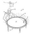
- FIG. 1 ais a perspective view of a traditional work environment including a video recording lighting system in accordance with at least one embodiment of the present invention
- FIG. 1 bis a perspective view of a rectangular conference table having a clustered lighting system in accordance with one embodiment of the present invention
- FIG. 2is a cross-sectional view of a portion of a desk incorporating a video recording lighting system in accordance with another embodiment of the present invention
- FIG. 3is a cross-sectional view of another desk incorporating a video recording lighting system in accordance with another embodiment of the present invention.
- FIG. 4is a perspective view of a podium incorporating a video recording lighting system in accordance with yet another embodiment of the present invention.
- FIG. 5is a perspective view of a portable video conferencing lighting system in accordance with still another embodiment of the present invention.
- FIG. 6is a perspective view of a personal computer incorporating a video recording lighting system in accordance with one other embodiment of the present invention.
- a traditional work or office environment 10 including over-head lighting 12projects a beam of light 14 downward onto an individual 16 positioned for recording by a video recording system 18 and, in particular, a video teleconferencing system.
- the individual 16is seated at a desk or table 20 .
- a beam of light 14 projected by the over-head light 12is ideal for lighting a work surface 22 of the desk 20 .
- the beam of light 14 projected downward from the over-head lighting source 12will create numerous shadowed areas in and about the face and upper body of the individual 16 .
- an undesirable image having numerous shadows that obscure the individualwill be captured for video teleconferencing using the video recording system 18 .
- the present inventionprovides a lighting source 24 designed to correctly light the individual 16 for video recording.
- the lighting source 24is designed to compensate for the beam of light 14 projected downward onto the individual 16 by the over-head light 12 . Specifically, by positioning the lighting source 24 below the face of the individual 16 when seated at the table 20 , the individual 16 is lit from below to project a beam of light 26 onto the areas that would otherwise be cast into shadow by the over-head light 12 .
- the lighting source 24may form a ring encircling a parameter of the table 20 to project the beam of light 26 radially from the table 20 toward individuals seated thereabouts.
- the lighting source 24may be formed using a plurality of individual lights.
- the lighting source 24may be formed from a plurality of light emitting diodes (LEDs).
- the individual lights in the lighting source 24may be arranged in the ring encircling the parameter of the table 20 at substantially even intervals.
- the lighting source 24may be clustered about specific areas around a table 20 .
- the lighting source 24 ′may be clustered along the central areas of each side, where individuals are more likely to be seated.
- the beam of light 26 projected by the lighting source 24is outside the visual range of the individual 16 . That is, it is contemplated that the beam of light 26 may be outside of the visual spectrum of light extending from approximately 380 nanometers (nm) to approximately 750 nm. For example, it is contemplated that the beam of light 26 may be in the near infrared range, approximately 700 or 750 nm to approximately 780 or 800 nm, or in the infrared range, greater than approximately 780 nm.
- the beam of light 26will not be detectable by the individual 16 , but will serve to adequately light the individual 16 with respect to the video recording system 18 . That is, since most traditional video recording cameras are capable of capturing light outside of the visual range, for example, infrared light, and do not distinguish between these light types, the viewable video provided from the video recording system 18 will show the individual 16 as being lighted (with visible light) by both beams of light 14 , 26 .
- the beam of non-visible light 26 emitted by the light source 24 positioned below the individual 16is undetectable by the individual 16 , the beam of light 26 does not interfere with the individual 16 by shining into the eyes, obscuring the individual's view, or otherwise providing the individual 16 with an uncomfortable work environment 10 .
- the lighting source 24emits light that is readily detectable by traditional, commercially available, video recording systems, it is widely useable and does not require any specially designed video conferencing systems. Rather, it can be readily used with most traditional video recording systems 18 .
- the light source 24may be pre-positioned to correctly light the individual 16 positioned before the video recording system 18 by integrating the light source 24 with the surrounding environment 10 .
- the light source 24may be integrated into the table 20 .
- the light source 24may be integrated into the top work surface 22 of the table 20 or other areas about the work environment 10 so as to project the beam of light 26 along a trajectory designed to correctly light the individual 16 for video recording.
- the light source 24may be configured to operate in concert with the video recording system 18 .
- the light source 24may be configured to turn “on” or “off” based on whether the camera is currently recording or on standby.
- the intensity of the light source 24may be controlled based on the focus or results of the video recording process. For example, by providing feedback regarding the current focus and white-balance of the video recording system 18 specific lights in the lighting system 24 may be turn “on” or “off” or the intensity of such lights may be adjusted to improve the lighting conditions and the resulting recordings.
- feedbackmay be provided to individuals using the lighting system 24 to indicate when light is being emitted and whether the user is optimally positioned for lighting.
- the light source 24may be integrated into a planar surface 28 such as are commonly found in tabletops, chairs, or other pieces of furniture.
- a planar surface 28it is contemplated that the light source 24 may be disposed below the planar surface 28 and encased under a cover 30 so that the planar surface 28 is unbroken by the light source 24 .
- the light source 24can be pre-positioned to correctly light an individual seated to work at the planar surface 28 , but will not interfere with the field of view positioned to record the individual during a video teleconferencing or other video recording process.
- the light source 24may be angled below the planar surface 28 so that the beam of light 26 emitted by the light source 24 is projected away form the planar surface 28 at an angle designed to adequately light an individual seated proximate to the planar surface 28 .
- the angled arrangement extending below the planar surface 28can be configured to emit the beam of light 26 at an angle designed to compensate for overhead lights and the shadows created by such lighting arrangements. Accordingly, the light source 24 may project a beam of light 26 to correctly light an individual positioned before a video recording system even when over-head lights are the dominate light source in the area.
- reflectors, refractors, filters, or dispersion layersmay be coupled with the light source 24 .
- a reflector 32may be positioned proximate to the light source 24 to reflect the beam of light 26 emitted by the light source 24 along the trajectory desired to adequately light an individual seated at the planar work surface 28 .
- the angled mounting described abovemay be foregone in favor of reflectors 32 positioned to reflect the beam of light radially toward an edge 34 of the work surface 28 , where individuals would be seated.
- a filter or dispersion layer 36may be formed over the cover 30 such that the beam of light 26 is substantially evenly distributed around the edge 34 of the work surface 28 .
- lighting source 24emits a beam of light 26 outside of the visual range, the beam of light 26 will not be perceived by an individual and; hence, will not cause the individual to squint or be otherwise uncomfortable. Accordingly, the light source 24 emits a beam of light 26 that is readily detectable by traditional, commercially available, video recording systems to improve the quality of image gathered by the video recording systems without adversely affecting the individuals lighted by the light source.
- one or more sensors 35may be arranged about the light source 24 to detect an overall intensity of the light emitted by the light source 24 .
- the feedback received from the sensor 35may be used to coordinate portions of the light system 24 with operation of a camera used in the video recording process.
- feedback from the sensor 35may be used to determine when the beam of light 26 emitted by the light source 24 is being reflected, such as by work materials resting on the work surface 28 .
- one or more visual or audio indicatorsmay be included to indicate to a user that the light source 24 is being blocked or impeded. That is, since it is preferable that the light source 24 emit light that is outside of the visual range, such visual or audio indicators may be included to alert a user to conditions that might interfere with proper lightings.
- the light source 24may also be integrated into a beveled edge 37 extending from a planar work surface 28 of a piece of furniture.
- the beveled edgemay be configured to extend from the planar work surface 28 at an angle designed to cast the beam of light 24 at an angle pre-configured to light an individual seated proximate to the planar work surface 28 . That is, in a manner similar to the angled mounting described with respect to FIG. 2 , the light source 24 can be mounted at an angle by being disposed along the planar surface forming beveled edge 37 .
- the light source 24may project a beam of light 26 to correctly light an individual positioned before a video recording system even when over-head lights are the dominate light source in the area.
- reflectors 32 , refractors filters, or dispersion layers 36may be coupled with the light source 24 .
- the lighting systems described with respect to FIGS. 2 and 3may be incorporated into a wide variety of furniture or devices.
- the light source 24may be incorporated into a podium 38 so as to project the beam of light 26 to light an individual standing at the podium 38 .
- the light source 24may be aligned along an upper end 40 of a planar surface 42 of the podium 38 .
- the light source 24may project a beam of light 26 to correctly light an individual standing at the podium 38 and being recorded by a video recording system, even when over-head lights are the dominate light source in the area.
- the light source 24may be positioned along a front edge of the podium 38 or along one or both lateral edges and aligned to project light along trajectories toward the location at which a podium user would stand. That is, the light source 24 may be positioned at any of a wide variety of positions so long as the locations for the light source(s) are select so that when a podium user places presentation materials on a top surface of the podium 38 , the materials are unlikely to block or impede the projected light.
- the light source 24may be incorporated within a portable device or part of a component of a video conferencing system.
- the portable devicemay be a speakerphone unit 44 or any other device, standalone or otherwise.
- the light source 24will be naturally positioned proximate to an individual desiring to use the speakerphone 44 .
- the speakerphone 44will be positioned in the center of the conference table 46 . Accordingly, the speakerphone is positioned to receive audio projected from individuals seated about the conference table and the light source 24 is positioned to project the beam of light 26 from the speakerphone 44 radially toward the individuals seated about the conference table 46 .
- the lighting systems described abovemay be incorporated into other devices such as a computer 48 .
- the computer 48may be a laptop computer, but the present invention is equally applicable with non-laptop computer designs.
- the computer 48includes a computer housing 50 at the top of which is a keyboard 52 surrounded by a bezel or housing 54 . Extending up from the housing 54 is a display 56 that is also surrounded by a bezel or housing 58 .
- the light source 24may be incorporated directly into the computer 48 so as to adequately light an individual seated before the computer 48 when using the computer 48 as a video conferencing system that includes a camera 60 .
- the light source 24may be disposed in the housing 54 surrounding the keyboard 52 proximate to the display 56 so that the light source 24 is not obscured when the keyboard 52 is used. It is contemplated that the light source 24 may be disposed within the housing 54 surrounding the keyboard 52 and angled, as described with respect to FIGS. 2 and 3 , to project a beam of light 26 to correctly light an individual positioned before the computer 48 even when over-head lights are the dominate light source in the area. Additionally or alternatively, it is contemplated that the light source 24 may be disposed in the housing 58 surrounding the display 56 near the camera 60 .
- the light source 24may be housed in any of a variety of materials.
- various plastics and glassesmay be used to house the light source 24 .
- the housing materialsmay be selected to match or complement the materials forming the device or furniture within which the light source 24 has been integrated.
- the light sourcemay be seamlessly integrated or may appear as a decorative inlay formed in the device or furniture.
- the light emitted by the light source 24is preferably outside of the range, individuals using the device or seated at the furniture, will not be drawn to distinguish the light source 24 from the device or furniture.
- various forms of feedbackmay be provided to the user to indicate that light is being emitted or that materials are blocking or impeding the light being emitted by the light source 24 so that a user can make adjustments as necessary.
- the above-described inventionprovides a system and method for quickly and easily lighting the focus of a video process when recording is conducted in non-traditional recording environments (i.e. recording studios) employing lighting, such as over-head lighting, that is undesirable for video recording.
- a system and methodis provided for correctly lighting individuals during a video conferencing process without requiring undue preparation, interfering with the field of view shown during the video conference, or creating uncomfortable working environments due to lights directed into the faces of those positioned on camera.
- the present inventionovercomes the drawbacks present in prior art systems by providing a lighting source that emits light outside of the visual range to light the focus of a video process.
- the lighting sourceemits light that is readily detectable by traditional, commercially available, video recording systems, but that is undetectable by individuals lighted by the light source.
- the light sourcemay project light to correctly light an individual positioned before the video recording system without causing the individual discomfort.
- the light sourcemay be pre-positioned to correctly light individuals (for example, to correct for over-head lights) positioned before the video system by integrating the light source with the surrounding environment, such as furniture pieces, portions of the video conferencing system, or portable devices like computers and speakerphones.
Landscapes
- Engineering & Computer Science (AREA)
- Multimedia (AREA)
- Signal Processing (AREA)
- Studio Devices (AREA)
Abstract
Description
Claims (30)
Priority Applications (1)
| Application Number | Priority Date | Filing Date | Title |
|---|---|---|---|
| US11/424,967US7893953B2 (en) | 2006-06-19 | 2006-06-19 | Video conferencing lighting system |
Applications Claiming Priority (1)
| Application Number | Priority Date | Filing Date | Title |
|---|---|---|---|
| US11/424,967US7893953B2 (en) | 2006-06-19 | 2006-06-19 | Video conferencing lighting system |
Publications (2)
| Publication Number | Publication Date |
|---|---|
| US20070291466A1 US20070291466A1 (en) | 2007-12-20 |
| US7893953B2true US7893953B2 (en) | 2011-02-22 |
Family
ID=38861326
Family Applications (1)
| Application Number | Title | Priority Date | Filing Date |
|---|---|---|---|
| US11/424,967Active2029-12-23US7893953B2 (en) | 2006-06-19 | 2006-06-19 | Video conferencing lighting system |
Country Status (1)
| Country | Link |
|---|---|
| US (1) | US7893953B2 (en) |
Cited By (26)
| Publication number | Priority date | Publication date | Assignee | Title |
|---|---|---|---|---|
| US9041865B2 (en) | 2012-06-08 | 2015-05-26 | Haworth, Inc. | Video switch |
| US9086610B2 (en) | 2012-02-03 | 2015-07-21 | Glow Enterprises, Llc | Illumination device |
| USD754797S1 (en) | 2015-07-09 | 2016-04-26 | Fissell Enterprises, Inc. | Gaming table |
| US9464796B2 (en) | 2012-02-03 | 2016-10-11 | Lumee, Llc | Illumination device |
| USD776849S1 (en)* | 2012-08-07 | 2017-01-17 | Jeremy J. Fissell | Table with illuminating perimeter |
| US9593842B2 (en) | 2012-02-03 | 2017-03-14 | Lumee Llc | Illumination device |
| US9642219B2 (en) | 2014-06-05 | 2017-05-02 | Steelcase Inc. | Environment optimization for space based on presence and activities |
| US9852388B1 (en) | 2014-10-03 | 2017-12-26 | Steelcase, Inc. | Method and system for locating resources and communicating within an enterprise |
| USD809070S1 (en) | 2016-11-03 | 2018-01-30 | Fissell Bros, Inc. | Back-illuminated translucent gaming table |
| US9921726B1 (en) | 2016-06-03 | 2018-03-20 | Steelcase Inc. | Smart workstation method and system |
| US9955318B1 (en) | 2014-06-05 | 2018-04-24 | Steelcase Inc. | Space guidance and management system and method |
| USD828829S1 (en) | 2015-01-13 | 2018-09-18 | Lumee Llc | Illumination case for electronic communications device |
| US10161752B1 (en) | 2014-10-03 | 2018-12-25 | Steelcase Inc. | Method and system for locating resources and communicating within an enterprise |
| US10264213B1 (en) | 2016-12-15 | 2019-04-16 | Steelcase Inc. | Content amplification system and method |
| US10353664B2 (en) | 2014-03-07 | 2019-07-16 | Steelcase Inc. | Method and system for facilitating collaboration sessions |
| USD854622S1 (en) | 2016-10-24 | 2019-07-23 | Fissell Bros, Inc. | Gaming table |
| US10433646B1 (en) | 2014-06-06 | 2019-10-08 | Steelcaase Inc. | Microclimate control systems and methods |
| US10495946B2 (en) | 2012-02-03 | 2019-12-03 | Case-Mate, Inc. | Illumination device |
| US10672221B2 (en)* | 2013-03-12 | 2020-06-02 | Tcs John Huxley Europe Limited | Gaming table |
| US10733371B1 (en) | 2015-06-02 | 2020-08-04 | Steelcase Inc. | Template based content preparation system for use with a plurality of space types |
| US11037394B2 (en)* | 2019-10-01 | 2021-06-15 | Igt | Tabletop/furniture game screen methods |
| US11073274B2 (en) | 2017-06-30 | 2021-07-27 | Arya Creations, Llc | Illumination devices |
| US11321643B1 (en) | 2014-03-07 | 2022-05-03 | Steelcase Inc. | Method and system for facilitating collaboration sessions |
| US11744376B2 (en) | 2014-06-06 | 2023-09-05 | Steelcase Inc. | Microclimate control systems and methods |
| US11984739B1 (en) | 2020-07-31 | 2024-05-14 | Steelcase Inc. | Remote power systems, apparatus and methods |
| US12118178B1 (en) | 2020-04-08 | 2024-10-15 | Steelcase Inc. | Wayfinding services method and apparatus |
Families Citing this family (14)
| Publication number | Priority date | Publication date | Assignee | Title |
|---|---|---|---|---|
| US20090095906A1 (en)* | 2007-10-11 | 2009-04-16 | Sony Ericsson Mobile Communications Ab | Image capturing |
| TWM342066U (en)* | 2007-12-24 | 2008-10-11 | Prodisc Technology Inc | Tabular body structure with light source |
| CA2787266C (en)* | 2010-01-14 | 2016-03-08 | Infection Prevention Technologies | Systems and methods for emitting radiant energy |
| US8780161B2 (en) | 2011-03-01 | 2014-07-15 | Hewlett-Packard Development Company, L.P. | System and method for modifying images |
| US9344673B1 (en)* | 2014-03-14 | 2016-05-17 | Brian K. Buchheit | Enhancing a camera oriented user interface via an eye focus guide |
| US9930290B2 (en)* | 2014-09-25 | 2018-03-27 | Steve H. McNelley | Communication stage and integrated systems |
| US11750772B2 (en) | 2014-09-25 | 2023-09-05 | Steve H. McNelley | Rear illuminated transparent communication terminals |
| US11099465B2 (en) | 2014-09-25 | 2021-08-24 | Steve H. McNelley | Communication stage and display systems |
| US10298877B2 (en)* | 2014-09-25 | 2019-05-21 | Steve H. McNelley | Communication stage and display systems |
| US11258983B2 (en) | 2014-09-25 | 2022-02-22 | Steve H. McNelley | Immersive communication terminals |
| US10841535B2 (en) | 2014-09-25 | 2020-11-17 | Steve H. McNelley | Configured transparent communication terminals |
| US10129506B2 (en) | 2014-09-25 | 2018-11-13 | Steve H. McNelley | Advanced transparent projection communication terminals |
| US10636317B2 (en) | 2016-05-26 | 2020-04-28 | University Of South Carolina | Automated remote learning device and system for using same |
| US20220070409A1 (en)* | 2020-09-01 | 2022-03-03 | Under Silver Lining Industries LLC | Lighting system for video conference participants |
Citations (9)
| Publication number | Priority date | Publication date | Assignee | Title |
|---|---|---|---|---|
| US20020110376A1 (en)* | 2001-02-08 | 2002-08-15 | Maclean Steven D. | Method and apparatus for calibrating a sensor for highlights and for processing highlights |
| US20030219237A1 (en)* | 2002-05-23 | 2003-11-27 | Image Premastering Services, Ltd. | Apparatus and method for digital recording of a film image |
| US20040070149A1 (en) | 2002-09-18 | 2004-04-15 | Lipscomb Steven Roy | Game table with integral lighting system |
| US20050024484A1 (en)* | 2003-07-31 | 2005-02-03 | Leonard Edwin R. | Virtual conference room |
| US20050248651A1 (en)* | 2004-05-10 | 2005-11-10 | Fuji Xerox Co., Ltd. | Conference recording device, conference recording method, and design method and storage media storing programs |
| US20060017805A1 (en)* | 2004-07-21 | 2006-01-26 | Polycom, Inc. | Conference unit controlling room functions |
| US20060109199A1 (en)* | 2004-11-24 | 2006-05-25 | Microsoft Corporation | Edge lighting system for interactive display surface |
| US20070173394A1 (en)* | 2006-01-24 | 2007-07-26 | Chia-Shun Lee | Paper cutting device with a cutting blade unit and a folding line maker |
| US20070274700A1 (en)* | 2006-05-24 | 2007-11-29 | Nokia Corporation | Handheld electronic device |
- 2006
- 2006-06-19USUS11/424,967patent/US7893953B2/enactiveActive
Patent Citations (10)
| Publication number | Priority date | Publication date | Assignee | Title |
|---|---|---|---|---|
| US20020110376A1 (en)* | 2001-02-08 | 2002-08-15 | Maclean Steven D. | Method and apparatus for calibrating a sensor for highlights and for processing highlights |
| US20030219237A1 (en)* | 2002-05-23 | 2003-11-27 | Image Premastering Services, Ltd. | Apparatus and method for digital recording of a film image |
| US20040070149A1 (en) | 2002-09-18 | 2004-04-15 | Lipscomb Steven Roy | Game table with integral lighting system |
| US20050093241A1 (en)* | 2002-09-18 | 2005-05-05 | World Poker Tour | Game table with integral lighting system and method for providing lighting of a game tournament suitable for television |
| US20050024484A1 (en)* | 2003-07-31 | 2005-02-03 | Leonard Edwin R. | Virtual conference room |
| US20050248651A1 (en)* | 2004-05-10 | 2005-11-10 | Fuji Xerox Co., Ltd. | Conference recording device, conference recording method, and design method and storage media storing programs |
| US20060017805A1 (en)* | 2004-07-21 | 2006-01-26 | Polycom, Inc. | Conference unit controlling room functions |
| US20060109199A1 (en)* | 2004-11-24 | 2006-05-25 | Microsoft Corporation | Edge lighting system for interactive display surface |
| US20070173394A1 (en)* | 2006-01-24 | 2007-07-26 | Chia-Shun Lee | Paper cutting device with a cutting blade unit and a folding line maker |
| US20070274700A1 (en)* | 2006-05-24 | 2007-11-29 | Nokia Corporation | Handheld electronic device |
Cited By (60)
| Publication number | Priority date | Publication date | Assignee | Title |
|---|---|---|---|---|
| US9593842B2 (en) | 2012-02-03 | 2017-03-14 | Lumee Llc | Illumination device |
| US9086610B2 (en) | 2012-02-03 | 2015-07-21 | Glow Enterprises, Llc | Illumination device |
| US9464796B2 (en) | 2012-02-03 | 2016-10-11 | Lumee, Llc | Illumination device |
| US10495946B2 (en) | 2012-02-03 | 2019-12-03 | Case-Mate, Inc. | Illumination device |
| US9485463B2 (en) | 2012-06-08 | 2016-11-01 | Haworth, Inc. | Video switch |
| US9041865B2 (en) | 2012-06-08 | 2015-05-26 | Haworth, Inc. | Video switch |
| USD776849S1 (en)* | 2012-08-07 | 2017-01-17 | Jeremy J. Fissell | Table with illuminating perimeter |
| US11049361B2 (en)* | 2013-03-12 | 2021-06-29 | Tcs John Huxley Europe Limited | Gaming table |
| US10672221B2 (en)* | 2013-03-12 | 2020-06-02 | Tcs John Huxley Europe Limited | Gaming table |
| US11150859B2 (en) | 2014-03-07 | 2021-10-19 | Steelcase Inc. | Method and system for facilitating collaboration sessions |
| US12001976B1 (en) | 2014-03-07 | 2024-06-04 | Steelcase Inc. | Method and system for facilitating collaboration sessions |
| US11321643B1 (en) | 2014-03-07 | 2022-05-03 | Steelcase Inc. | Method and system for facilitating collaboration sessions |
| US10353664B2 (en) | 2014-03-07 | 2019-07-16 | Steelcase Inc. | Method and system for facilitating collaboration sessions |
| US12324072B2 (en) | 2014-06-05 | 2025-06-03 | Steelcase Inc. | Environment optimization for space based on presence and activities |
| US9642219B2 (en) | 2014-06-05 | 2017-05-02 | Steelcase Inc. | Environment optimization for space based on presence and activities |
| US11307037B1 (en) | 2014-06-05 | 2022-04-19 | Steelcase Inc. | Space guidance and management system and method |
| US10225707B1 (en) | 2014-06-05 | 2019-03-05 | Steelcase Inc. | Space guidance and management system and method |
| US11280619B1 (en) | 2014-06-05 | 2022-03-22 | Steelcase Inc. | Space guidance and management system and method |
| US10057963B2 (en) | 2014-06-05 | 2018-08-21 | Steelcase Inc. | Environment optimization for space based on presence and activities |
| US11979959B1 (en) | 2014-06-05 | 2024-05-07 | Steelcase Inc. | Environment optimization for space based on presence and activities |
| US11212898B2 (en) | 2014-06-05 | 2021-12-28 | Steelcase Inc. | Environment optimization for space based on presence and activities |
| US11402216B1 (en) | 2014-06-05 | 2022-08-02 | Steelcase Inc. | Space guidance and management system and method |
| US9955318B1 (en) | 2014-06-05 | 2018-04-24 | Steelcase Inc. | Space guidance and management system and method |
| US10561006B2 (en) | 2014-06-05 | 2020-02-11 | Steelcase Inc. | Environment optimization for space based on presence and activities |
| US11085771B1 (en) | 2014-06-05 | 2021-08-10 | Steelcase Inc. | Space guidance and management system and method |
| US12375874B1 (en) | 2014-06-05 | 2025-07-29 | Steelcase Inc. | Space guidance and management system and method |
| US11402217B1 (en) | 2014-06-05 | 2022-08-02 | Steelcase Inc. | Space guidance and management system and method |
| US10433646B1 (en) | 2014-06-06 | 2019-10-08 | Steelcaase Inc. | Microclimate control systems and methods |
| US11744376B2 (en) | 2014-06-06 | 2023-09-05 | Steelcase Inc. | Microclimate control systems and methods |
| US11143510B1 (en) | 2014-10-03 | 2021-10-12 | Steelcase Inc. | Method and system for locating resources and communicating within an enterprise |
| US11687854B1 (en) | 2014-10-03 | 2023-06-27 | Steelcase Inc. | Method and system for locating resources and communicating within an enterprise |
| US11713969B1 (en) | 2014-10-03 | 2023-08-01 | Steelcase Inc. | Method and system for locating resources and communicating within an enterprise |
| US10970662B2 (en) | 2014-10-03 | 2021-04-06 | Steelcase Inc. | Method and system for locating resources and communicating within an enterprise |
| US11168987B2 (en) | 2014-10-03 | 2021-11-09 | Steelcase Inc. | Method and system for locating resources and communicating within an enterprise |
| US9852388B1 (en) | 2014-10-03 | 2017-12-26 | Steelcase, Inc. | Method and system for locating resources and communicating within an enterprise |
| US10121113B1 (en) | 2014-10-03 | 2018-11-06 | Steelcase Inc. | Method and system for locating resources and communicating within an enterprise |
| US10161752B1 (en) | 2014-10-03 | 2018-12-25 | Steelcase Inc. | Method and system for locating resources and communicating within an enterprise |
| USD828829S1 (en) | 2015-01-13 | 2018-09-18 | Lumee Llc | Illumination case for electronic communications device |
| US10733371B1 (en) | 2015-06-02 | 2020-08-04 | Steelcase Inc. | Template based content preparation system for use with a plurality of space types |
| US11100282B1 (en) | 2015-06-02 | 2021-08-24 | Steelcase Inc. | Template based content preparation system for use with a plurality of space types |
| USD754797S1 (en) | 2015-07-09 | 2016-04-26 | Fissell Enterprises, Inc. | Gaming table |
| US11690111B1 (en) | 2016-06-03 | 2023-06-27 | Steelcase Inc. | Smart workstation method and system |
| US10459611B1 (en) | 2016-06-03 | 2019-10-29 | Steelcase Inc. | Smart workstation method and system |
| US12213191B1 (en) | 2016-06-03 | 2025-01-28 | Steelcase Inc. | Smart workstation method and system |
| US9921726B1 (en) | 2016-06-03 | 2018-03-20 | Steelcase Inc. | Smart workstation method and system |
| US11330647B2 (en) | 2016-06-03 | 2022-05-10 | Steelcase Inc. | Smart workstation method and system |
| US11956838B1 (en) | 2016-06-03 | 2024-04-09 | Steelcase Inc. | Smart workstation method and system |
| USD854622S1 (en) | 2016-10-24 | 2019-07-23 | Fissell Bros, Inc. | Gaming table |
| USD809070S1 (en) | 2016-11-03 | 2018-01-30 | Fissell Bros, Inc. | Back-illuminated translucent gaming table |
| US11652957B1 (en) | 2016-12-15 | 2023-05-16 | Steelcase Inc. | Content amplification system and method |
| US10638090B1 (en) | 2016-12-15 | 2020-04-28 | Steelcase Inc. | Content amplification system and method |
| US10897598B1 (en) | 2016-12-15 | 2021-01-19 | Steelcase Inc. | Content amplification system and method |
| US12231810B1 (en) | 2016-12-15 | 2025-02-18 | Steelcase Inc. | Content amplification system and method |
| US10264213B1 (en) | 2016-12-15 | 2019-04-16 | Steelcase Inc. | Content amplification system and method |
| US11190731B1 (en) | 2016-12-15 | 2021-11-30 | Steelcase Inc. | Content amplification system and method |
| US11073274B2 (en) | 2017-06-30 | 2021-07-27 | Arya Creations, Llc | Illumination devices |
| US11037394B2 (en)* | 2019-10-01 | 2021-06-15 | Igt | Tabletop/furniture game screen methods |
| US12118178B1 (en) | 2020-04-08 | 2024-10-15 | Steelcase Inc. | Wayfinding services method and apparatus |
| US12341360B1 (en) | 2020-07-31 | 2025-06-24 | Steelcase Inc. | Remote power systems, apparatus and methods |
| US11984739B1 (en) | 2020-07-31 | 2024-05-14 | Steelcase Inc. | Remote power systems, apparatus and methods |
Also Published As
| Publication number | Publication date |
|---|---|
| US20070291466A1 (en) | 2007-12-20 |
Similar Documents
| Publication | Publication Date | Title |
|---|---|---|
| US7893953B2 (en) | Video conferencing lighting system | |
| US11849252B2 (en) | Method and system for filming | |
| US11442339B2 (en) | Method and system for filming | |
| US9641796B2 (en) | Flattened light reflection for telepresence | |
| US7619366B2 (en) | System for and method of controlling a light source and lighting arrangement | |
| US8228371B2 (en) | Projection screen and camera array | |
| US7677746B2 (en) | Illumination device | |
| US7841729B2 (en) | Webcam illuminator device | |
| CN1918532A (en) | Interactive video window display system | |
| TW200500784A (en) | Reflection type screen | |
| US12078305B2 (en) | Integrated light-reflecting mirror system and method | |
| US20170099426A1 (en) | Led speaker identifier system | |
| US20150362148A1 (en) | Personal Video Conference Lighting Assembly | |
| JPH057320A (en) | Intercom slave machine provided with camera | |
| JP6114774B2 (en) | Imaging method and system | |
| KR101793656B1 (en) | Platform apparatus equipped with light | |
| JP2501139B2 (en) | Doorphone with camera | |
| FI86130C (en) | BILDTELEFONTERMINAL ELLER MOTSVARANDE. | |
| JPH0234121B2 (en) | ||
| JPS6336564Y2 (en) | ||
| CN120538004A (en) | Lamp and electronic equipment | |
| EA047966B1 (en) | METHOD AND DEVICE FOR CAPTURED IMAGE OF A PERSON PROJECTED AS "PEPPER'S GHOST" | |
| Winckler | SMPTE Tutorial Paper: The Objectives of Lighting | |
| JPS61126702A (en) | Lighting apparatus for tv conference room |
Legal Events
| Date | Code | Title | Description |
|---|---|---|---|
| AS | Assignment | Owner name:STEELCASE DEVELOPMENT CORPORATION, MICHIGAN Free format text:ASSIGNMENT OF ASSIGNORS INTEREST;ASSIGNORS:KRESTAKOS, ROBERT G.;MEAD, MATTHEW A.;STANFIELD, JOEL;AND OTHERS;REEL/FRAME:018080/0810;SIGNING DATES FROM 20060613 TO 20060619 | |
| AS | Assignment | Owner name:STEELCASE INC., MICHIGAN Free format text:MERGER;ASSIGNOR:STEELCASE DEVELOPMENT CORPORATION;REEL/FRAME:020360/0944 Effective date:20071017 Owner name:STEELCASE INC.,MICHIGAN Free format text:MERGER;ASSIGNOR:STEELCASE DEVELOPMENT CORPORATION;REEL/FRAME:020360/0944 Effective date:20071017 | |
| STCF | Information on status: patent grant | Free format text:PATENTED CASE | |
| CC | Certificate of correction | ||
| FPAY | Fee payment | Year of fee payment:4 | |
| MAFP | Maintenance fee payment | Free format text:PAYMENT OF MAINTENANCE FEE, 8TH YEAR, LARGE ENTITY (ORIGINAL EVENT CODE: M1552); ENTITY STATUS OF PATENT OWNER: LARGE ENTITY Year of fee payment:8 | |
| MAFP | Maintenance fee payment | Free format text:PAYMENT OF MAINTENANCE FEE, 12TH YEAR, LARGE ENTITY (ORIGINAL EVENT CODE: M1553); ENTITY STATUS OF PATENT OWNER: LARGE ENTITY Year of fee payment:12 |