US7893882B2 - Pattern shaping of RF emission patterns - Google Patents
Pattern shaping of RF emission patternsDownload PDFInfo
- Publication number
- US7893882B2 US7893882B2US11/971,210US97121008AUS7893882B2US 7893882 B2US7893882 B2US 7893882B2US 97121008 AUS97121008 AUS 97121008AUS 7893882 B2US7893882 B2US 7893882B2
- Authority
- US
- United States
- Prior art keywords
- shaping plate
- antenna array
- radiation pattern
- metallic
- wireless device
- Prior art date
- Legal status (The legal status is an assumption and is not a legal conclusion. Google has not performed a legal analysis and makes no representation as to the accuracy of the status listed.)
- Expired - Fee Related, expires
Links
Images


Classifications
- H—ELECTRICITY
- H01—ELECTRIC ELEMENTS
- H01Q—ANTENNAS, i.e. RADIO AERIALS
- H01Q9/00—Electrically-short antennas having dimensions not more than twice the operating wavelength and consisting of conductive active radiating elements
- H01Q9/04—Resonant antennas
- H01Q9/16—Resonant antennas with feed intermediate between the extremities of the antenna, e.g. centre-fed dipole
- H—ELECTRICITY
- H01—ELECTRIC ELEMENTS
- H01Q—ANTENNAS, i.e. RADIO AERIALS
- H01Q1/00—Details of, or arrangements associated with, antennas
- H01Q1/12—Supports; Mounting means
- H01Q1/22—Supports; Mounting means by structural association with other equipment or articles
- H01Q1/24—Supports; Mounting means by structural association with other equipment or articles with receiving set
- H01Q1/241—Supports; Mounting means by structural association with other equipment or articles with receiving set used in mobile communications, e.g. GSM
- H01Q1/242—Supports; Mounting means by structural association with other equipment or articles with receiving set used in mobile communications, e.g. GSM specially adapted for hand-held use
- H01Q1/243—Supports; Mounting means by structural association with other equipment or articles with receiving set used in mobile communications, e.g. GSM specially adapted for hand-held use with built-in antennas
- H—ELECTRICITY
- H01—ELECTRIC ELEMENTS
- H01Q—ANTENNAS, i.e. RADIO AERIALS
- H01Q1/00—Details of, or arrangements associated with, antennas
- H01Q1/36—Structural form of radiating elements, e.g. cone, spiral, umbrella; Particular materials used therewith
- H01Q1/38—Structural form of radiating elements, e.g. cone, spiral, umbrella; Particular materials used therewith formed by a conductive layer on an insulating support
- H—ELECTRICITY
- H01—ELECTRIC ELEMENTS
- H01Q—ANTENNAS, i.e. RADIO AERIALS
- H01Q1/00—Details of, or arrangements associated with, antennas
- H01Q1/42—Housings not intimately mechanically associated with radiating elements, e.g. radome
- H—ELECTRICITY
- H01—ELECTRIC ELEMENTS
- H01Q—ANTENNAS, i.e. RADIO AERIALS
- H01Q19/00—Combinations of primary active antenna elements and units with secondary devices, e.g. with quasi-optical devices, for giving the antenna a desired directional characteristic
- H—ELECTRICITY
- H01—ELECTRIC ELEMENTS
- H01Q—ANTENNAS, i.e. RADIO AERIALS
- H01Q19/00—Combinations of primary active antenna elements and units with secondary devices, e.g. with quasi-optical devices, for giving the antenna a desired directional characteristic
- H01Q19/02—Details
- H01Q19/021—Means for reducing undesirable effects
- H—ELECTRICITY
- H01—ELECTRIC ELEMENTS
- H01Q—ANTENNAS, i.e. RADIO AERIALS
- H01Q21/00—Antenna arrays or systems
- H01Q21/24—Combinations of antenna units polarised in different directions for transmitting or receiving circularly and elliptically polarised waves or waves linearly polarised in any direction
- H01Q21/26—Turnstile or like antennas comprising arrangements of three or more elongated elements disposed radially and symmetrically in a horizontal plane about a common centre
- H—ELECTRICITY
- H01—ELECTRIC ELEMENTS
- H01Q—ANTENNAS, i.e. RADIO AERIALS
- H01Q9/00—Electrically-short antennas having dimensions not more than twice the operating wavelength and consisting of conductive active radiating elements
- H01Q9/04—Resonant antennas
- H01Q9/16—Resonant antennas with feed intermediate between the extremities of the antenna, e.g. centre-fed dipole
- H01Q9/28—Conical, cylindrical, cage, strip, gauze, or like elements having an extended radiating surface; Elements comprising two conical surfaces having collinear axes and adjacent apices and fed by two-conductor transmission lines
- H01Q9/285—Planar dipole
Definitions
- the present inventiongenerally relates to wireless communications and more particularly to changing radio frequency (RF) emission patterns with respect to one or more antenna arrays.
- RFradio frequency
- a wireless link in an Institute of Electrical and Electronic Engineers (IEEE) 802.11 networkmay be susceptible to interference from other access points and stations, other radio transmitting devices, and changes or disturbances in the wireless link environment between an access point and remote receiving node.
- the interferencemay degrade the wireless link thereby forcing communication at a lower data rate.
- the interferencemay, however, be sufficiently strong as to disrupt the wireless link altogether.
- a data sourceis coupled to two or more physically separated omnidirectional antennas.
- An access pointmay select one of the omnidirectional antennas by which to maintain a wireless link. Because of the separation between the omnidirectional antennas, each antenna experiences a different signal environment and corresponding interference level with respect to the wireless link.
- a switching networkcouples the data source to whichever of the omnidirectional antennas experiences the least interference in the wireless link.
- EMIelectromagnetic interference
- This interferencemay be encountered (or created) with respect to another nearby wireless environments (e.g., between the floors of an office building or hot spots scattered amongst a single room).
- EMIelectromagnetic interference
- shieldingin or proximate an antenna enclosure.
- Shielding a metallic enclosureis imperfect, however, because the conductivity of all metals is finite. Because metallic shields have less than infinite conductivity, part of the field is transmitted across the boundary and supports a current in the metal. The amount of current flow at any depth in the shield and the rate of decay are governed by the conductivity of the metal, its permeability, and the frequency and amplitude of the field source.
- a gap or seam in a shieldwill allow electromagnetic fields to radiate through the shield unless the current continuity can be preserved across the gaps.
- An EMI gasketis, therefore, often used to preserve continuity or current flow in the shield. If a gasket is made of material identical to the walls of the shielded enclosure, the current density in the gasket will be the same.
- An EMI gasketfails to allow for shaping of RF patterns and gain control as the gasket is implemented to seal openings in an enclosure as to prevent transmission of EMI.
- a metallic shaping plateis located in or on the interior housing of a wireless device.
- An antenna array located in the housingmay generate a radiation pattern when elements of the array are coupled to a radio frequency feed port.
- the metallic shaping platemay, as a result of its proximity to the array, influence the pattern being generated by the array. The result may be an increase in the gain of the array while reducing effects of EMI.
- a wireless devicein one claimed embodiment, includes a horizontal antenna array, a housing enclosing the horizontal antenna array, and a metallic shaping plate.
- the horizontal antenna arrayincludes antenna elements, the selectively coupling of which to a radio frequency feed port generates a substantially omnidirectional radiation pattern having less directionality than the directional radiation pattern of a single antenna element.
- the substantially omnidirectional radiation patternis substantially in the plane of the horizontal antenna array.
- the metallic shaping plateis coupled to the interior of the housing and is substantially centered with respect to the central, vertical axis of the horizontal antenna array.
- the placement of the metallic shaping platecauses a change in the substantially omnidirectional radiation pattern generated by the horizontal antenna array.
- a metallic shaping plateis configured to be coupled to the interior of a housing for a horizontal antenna array.
- the shaping plateis further configured to be substantially centered with respect to the central, vertical axis of the horizontal antenna array. The placement of the shaping plate causes a change in a radiation pattern generated by the horizontal antenna array.
- FIG. 1illustrates a wireless device including a horizontal antenna array and a substantially circular metallic shaping plate effectuating a change in a radiation pattern emitted by the horizontal antenna array.
- FIG. 2Aillustrates a horizontally polarized antenna array with selectable elements as may be may be implemented in a wireless device like that described in FIG. 1 .
- FIG. 2Billustrates an alternative embodiment of a horizontally polarized antenna array with selectable elements as may be implemented in a wireless device like that described in FIG. 1 .
- FIG. 3illustrates a wireless multiple-input-multiple-output (MIMO) antenna system having multiple antennas and multiple radios as may be implemented in a wireless device like that described in FIG. 1 .
- MIMOmultiple-input-multiple-output
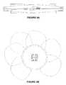
- FIG. 4Aillustrates a horizontally narrow embodiment of a MIMO antenna apparatus as may be implemented in a wireless device like that described in FIG. 1 .
- FIG. 4Billustrates a corresponding radiation pattern as may be generated by the embodiment illustrated in FIG. 4A .
- FIG. 5illustrates an alternative embodiment of FIG. 1 , wherein the metallic shaping plate is a metallic ring situated in a plastic or other non-metallic enclosure.
- FIG. 6illustrates a further embodiment of the present invention wherein the metallic shaping plate corresponds, in part, to the element layout design of the antenna array.
- FIG. 1illustrates a wireless device 100 including a horizontal antenna array 110 and a substantially circular metallic shaping plate 120 for effectuating a change in a radiation pattern emitted by the horizontal antenna array 110 .
- the horizontal array 110 of FIG. 1may include a plurality of antenna elements coupled to a radio frequency feed port. Selectively coupling two or more of the antenna elements to the radio frequency feed port may generate a substantially omnidirectional radiation pattern having less directionality than the directional radiation pattern of a single antenna element.
- the substantially omnidirectional radiation patternmay be substantially in the plane of the horizontal antenna array.
- the horizontal antenna arraymay include multiple selectively coupled directors configured to cause a change in the substantially omnidirectional radiation pattern generated by the horizontal antenna array.
- the antenna elementsmay be permanently coupled to a radio frequency feed port.
- the directorsmay be configured such that the effective length of the directors may change through selective coupling of one or more directors to one another.
- a series of interrupted and individual directors that are 0.1 cm in lengthmay be selectively coupled in a manner similar to the selective coupling of the aforementioned antenna elements.
- the directorsmay effectively become reflectors that reflect and otherwise shape the RF pattern emitted by the active antenna elements.
- RF energy emitted by an antenna arraymay be focused through these reflectors (and/or directors) to address particular nuances of a given wireless environment.
- Similar selectively coupled directorsmay operate with respect to a metallic shaping plate as is further discussed below.
- a horizontal antenna array110
- vertical or off-axis antenna arraysmay also be implemented in the practice of the present invention.
- multiple polarization antennase.g., an antenna system comprising a two horizontal and a single vertical antenna array
- the horizontal antenna array 110is enclosed within housing 130 .
- the size and configuration of the housing 130may vary depending on the exact nature of the wireless device the housing 130 encompasses.
- the housing 130may correspond to that of a wireless router that creates a wireless network via a broadband connection in a home or office.
- the housing 130may, alternatively, correspond to a wireless access point like that of U.S. design patent application Ser. No. 29/292,091.
- the physical housing of these devicesmay be a light-weight plastic that offer protection and ventilation to components located inside.
- the housing of the wireless devicemay, however, be constructed of any material subject to the whims of the particular manufacturer.
- FIG. 1also illustrates a metallic shaping plate 120 coupled to the interior of the housing 130 .
- the metallic shaping plate 120is substantially centered with respect to the central, vertical axis of the horizontal antenna array 110 .
- the static position of the metallic shaping plate 120causes a change in the substantially omnidirectional radiation pattern generated by the horizontal antenna array 110 .
- the metallic shaping plate 120effectuates such a change in the radiation pattern by ‘flattening’ the radiation pattern emitted by the antenna array 110 . By flattening the pattern, the gain of the generated radiation pattern is increased.
- the tilt of the radiation patternmay also be influenced by, for example, the specific composition, thickness or shape of the plate 120 .
- the plate 120is substantially circular and uniform in thickness and manufacture. In other embodiments, the shape, thickness and material used in manufacture may differ throughout the plate.
- the metallic shaping plate 120may be coupled to or operate in conjunction with a series of selectively coupled directors.
- the metallic shaping plate 120 and selectively coupled directorsmay be collectively configured to cause a change in the radiation pattern generated by the horizontal antenna array 110 .
- the selective coupling of the directorsmay be similar to the coupling utilized with respect to directors located on the array 110 .
- the metallic shaping plate 120may be coupled to the interior of the housing 130 using a permanent adhesive. In such an embodiment, removal of the plate 120 —be it intentional or accidental—may require reapplication of an adhesive to the plate 120 and the housing 130 interior.
- the plate 120may also be coupled using a reusable adhesive or other fastener (e.g., Velcro®) such that the plate 120 may be easily removed and reapplied.
- FIG. 2Aillustrates the antenna array 110 of FIG. 1 in one embodiment of the present invention.
- the antenna array 110 of this embodimentincludes a substrate (considered as the plane of FIG. 2A ) having a first side (depicted as solid lines 205 ) and a second side (depicted as dashed lines 225 ) substantially parallel to the first side.
- the substrateincludes a printed circuit board (PCB) such as FR4, Rogers 4003, or other dielectric material.
- PCBprinted circuit board
- the antenna array 110 of FIG. 2Aincludes a radio frequency feed port 220 and four antenna elements 205 a - 205 d . Although four modified dipoles (i.e., antenna elements) are depicted, more or fewer antenna elements may be implemented. Although the antenna elements 205 a - 205 d of FIG. 2A are oriented substantially to edges of a square shaped substrate so as to minimize the size of the antenna array 110 , other configurations may be implemented.
- the antenna elements 205 a - 205 dform a radially symmetrical layout about the radio frequency feed port 220 , a number of non-symmetrical layouts, rectangular layouts, and layouts symmetrical in only one axis may be implemented. Furthermore, the antenna elements 205 a - 205 d need not be of identical dimension, although depicted as such in FIG. 2A .
- the antenna array 110includes a ground component 225 .
- a portione.g., the portion 225 a
- the ground component 225is configured to form a modified dipole in conjunction with the antenna element 205 a .
- the dipoleis completed for each of the antenna elements 205 a - 205 d by respective conductive traces 225 a - 225 d extending in mutually-opposite directions.
- the resultant modified dipoleprovides a horizontally polarized directional radiation pattern (i.e., substantially in the plane of the antenna array 110 ).
- each of the modified dipolesmay incorporate one or more loading structures 210 .
- the loading structure 210is configured to slow down electrons, changing the resonance of each modified dipole, thereby making the modified dipole electrically shorter. At a given operating frequency, providing the loading structures 210 allows the dimension of the modified dipole to be reduced. Providing the loading structures 210 for all of the modified dipoles of the antenna array 110 minimizes the size of the antenna array 110 .
- FIG. 2Billustrates an alternative embodiment of the antenna array 110 of FIG. 1 .
- the antenna array 110 of this embodimentincludes one or more directors 230 .
- the directors 230include passive elements that constrain the directional radiation pattern of the modified dipoles formed by antenna elements 206 a - 206 d in conjunction with portions 226 a - 226 d of the ground component (for clarity, only 206 a and 226 a labeled). Because of the directors 230 , the antenna elements 206 and the portions 226 are slightly different in configuration than the antenna elements 205 and portions 225 of FIG. 2A .
- Directors 230may be placed on either side of the substrate. Additional directors (not shown) may also be included to further constrain the directional radiation pattern of one or more of the modified dipoles.
- the radio frequency feed port 220 of FIGS. 2A and 2Bis configured to receive an RF signal from an RF generating device such as a radio.
- An antenna element selector(not shown) may be used to couple the radio frequency feed port 220 to one or more of the antenna elements 205 .
- the antenna element selectormay comprise an RF switch such as a PIN diode, a GaAs FET, or virtually any RF switching device.
- An antenna element selectormay includes four PIN diodes, each PIN diode connecting one of the antenna elements 205 a - 205 d to the radio frequency feed port 220 .
- the PIN diodemay include a single-pole single-throw switch to switch each antenna element either on or off (i.e., couple or decouple each of the antenna elements 205 a - 205 d to the radio frequency feed port 220 ).
- a series of control signalsmay be used to bias each PIN diode. With the PIN diode forward biased and conducting a DC current, the PIN diode switch is on, and the corresponding antenna element is selected. With the diode reverse biased, the PIN diode switch is off.
- the radio frequency feed port 220 and the PIN diodes of the antenna element selectormay both be on the side of the substrate with the antenna elements 205 a - 205 d .
- One or more light emitting diodesmay be coupled to the antenna element selector as a visual indicator of which of the antenna elements 205 a - 205 d is on or off.
- a light emitting diodemay be placed in circuit with the PIN diode so that the light emitting diode is lit when the corresponding antenna element 205 is selected.
- the antenna componentsmay be formed from RF conductive material.
- the antenna elements 205 a - 205 d and the ground component 225may be formed from metal or other RF conducting material.
- each antenna element 205 a - 205 dis coplanar with the ground component 225 .
- the antenna componentsmay also be conformally mounted to the housing of the system 100 .
- the antenna element selectormay comprise a separate structure (not shown) from the antenna elements 205 a - 205 d .
- the antenna element selectormay be mounted on a relatively small PCB and the PCB may be electrically coupled to the antenna elements 205 a - 205 d .
- the switch PCBis soldered directly to the antenna elements 205 a - 205 d.
- FIG. 3illustrates a wireless MIMO antenna system having multiple antennas and multiple radios.
- a MIMO antenna systemmay be used as (or part of) the horizontal array 110 of FIG. 1 .
- the wireless MIMO antenna system 300 illustrated in FIG. 3may be representative of a transmitter and/or a receiver such as an 802.11 access point or an 802.11 receiver.
- System 300may also be representative of a set-top box, a laptop computer, television, Personal Computer Memory Card International Association (PCMCIA) card, Voice over Internet Protocol (VoIP) telephone, or handheld gaming device.
- PCMCIAPersonal Computer Memory Card International Association
- VoIPVoice over Internet Protocol
- Wireless MIMO antenna system 300may include a communication device for generating a radio frequency signal (e.g., in the case of transmitting node). Wireless MIMO antenna system 300 may also or alternatively receive data from a router connected to the Internet. Wireless MIMO antenna system 300 may then transmit that data to one or more of the remote receiving nodes. For example, the data may be video data transmitted to a set-top box for display on a television or video display.
- the wireless MIMO antenna system 300may form a part of a wireless local area network (e.g., a mesh network) by enabling communications among several transmission and/or receiving nodes. Although generally described as transmitting to a remote receiving node, the wireless MIMO antenna system 300 of FIG. 3 may also receive data subject to the presence of appropriate circuitry. Such circuitry may include but is not limited to a decoder, downconversion circuitry, samplers, digital-to-analog converters, filters, and so forth.
- Wireless MIMO antenna system 300includes a data encoder 301 for encoding data into a format appropriate for transmission to the remote receiving node via parallel radios 320 and 321 . While two radios are illustrated in FIG. 3 , additional radios or RF chains may be utilized.
- Data encoder 301may include data encoding elements such as direct sequence spread-spectrum (DSSS) or Orthogonal Frequency Division Multiplex (OFDM) encoding mechanisms to generate baseband data streams in an appropriate format.
- Data encoder 301may include hardware and/or software elements for converting data received into the wireless MIMO antenna system 300 into data packets compliant with the IEEE 802.11 format.
- Radios 320 and 321include transmitter or transceiver elements configured to upconvert the baseband data streams from the data encoder 301 to radio signals. Radios 320 and 321 thereby establish and maintain the wireless link. Radios 320 and 321 may include direct-to-RF upconverters or heterodyne upconverters for generating a first RF signal and a second RF signal, respectively. Generally, the first and second RF signals are at the same center frequency and bandwidth but may be offset in time or otherwise space-time coded.
- Wireless MIMO antenna system 300further includes a circuit (e.g., switching network) 330 for selectively coupling the first and second RF signals from the parallel radios 320 and 321 to an antenna apparatus 340 having multiple antenna elements 340 A-F.
- Antenna elements 340 A-Fmay include individually selectable antenna elements such that each antenna element 340 A-F may be electrically selected (e.g., switched on or off). By selecting various combinations of the antenna elements 340 A-F, the antenna apparatus 340 may form a “pattern agile” or reconfigurable radiation pattern. If certain or substantially all of the antenna elements 340 A-F are switched on, for example, the antenna apparatus 340 may form an omnidirectional radiation pattern.
- the patternmay include both vertically and horizontally polarized energy, which may also be referred to as diagonally polarized radiation.
- the antenna apparatus 340may form various directional radiation patterns, depending upon which of the antenna elements 340 A-F are turned on.
- Wireless MIMO antenna system 300may also include a controller 350 coupled to the data encoder 301 , the radios 320 and 321 , and the circuit 330 via a control bus 355 .
- the controller 350may include hardware (e.g., a microprocessor and logic) and/or software elements to control the operation of the wireless MIMO antenna system 300 .
- the controller 350may select a particular configuration of antenna elements 340 A-F that minimizes interference over the wireless link to the remote receiving device. If the wireless link experiences interference, for example due to other radio transmitting devices, or changes or disturbances in the wireless link between the wireless MIMO antenna system 300 and the remote receiving device, the controller 350 may select a different configuration of selected antenna elements 340 A-F via the circuit 330 to change the resulting radiation pattern and minimize the interference. For example, the controller 350 may select a configuration of selected antenna elements 340 A-F corresponding to a maximum gain between the wireless system 300 and the remote receiving device. Alternatively, the controller 350 may select a configuration of selected antenna elements 340 A-F corresponding to less than maximal gain, but corresponding to reduced interference in the wireless link.
- Controller 350may also transmit a data packet using a first subgroup of antenna elements 340 A-F coupled to the radio 320 and simultaneously send the data packet using a second group of antenna elements 340 A-F coupled to the radio 321 . Controller 350 may change the group of antenna elements 340 A-F coupled to the radios 320 and 321 on a packet-by-packet basis. Methods performed by the controller 350 with respect to a single radio having access to multiple antenna elements are further described in U.S. patent publication number US 2006-0040707 A1. These methods are also applicable to the controller 350 having control over multiple antenna elements and multiple radios.
- a MIMO antenna apparatusmay include a number of modified slot antennas and/or modified dipoles configured to transmit and/or receive horizontal polarization.
- the MIMO antenna apparatusmay further include a number of modified dipoles to provide vertical polarization. Examples of such antennas include those disclosed in U.S. patent application Ser. No. 11/413,461.
- Each dipole and each slotprovides gain (with respect to isotropic) and a polarized directional radiation pattern.
- the slots and the dipolesmay be arranged with respect to each other to provide offset radiation patterns.
- the antenna apparatusmay form a substantially omnidirectional radiation pattern with vertical polarization.
- the antenna apparatusmay form a substantially omnidirectional radiation pattern with horizontal polarization. Diagonally polarized radiation patterns may also be generated.
- the antenna apparatusmay easily be manufactured from common planar substrates such as an FR4 PCB.
- the PCBmay be partitioned into portions including one or more elements of the antenna apparatus, which portions may then be arranged and coupled (e.g., by soldering) to form a non-planar antenna apparatus having a number of antenna elements.
- the slotsmay be integrated into or conformably mounted to a housing of the system, to minimize cost and size of the system, and to provide support for the antenna apparatus.
- FIG. 4Aillustrates a horizontally narrow embodiment of a MIMO antenna apparatus (as generally described in FIG. 3 ) and as may be implemented in a wireless device like that described in FIG. 1 .
- FIG. 4Billustrates a corresponding radiation pattern as may be generated by the embodiment illustrated in FIG. 4A .
- horizontally polarized parasitic elementsmay be positioned about a central omnidirectional antenna. All elements (i.e., the parasitic elements and central omni) may be etched on the same PCB to simplify manufacturability. Switching elements may change the length of parasitic thereby making them transparent to radiation. Alternatively, switching elements may cause the parasitic elements to reflect energy back towards the driven dipole resulting in higher gain in that direction. An opposite parasitic element may be configured to function as a direction to increase gain.
- Other details as to the manufacture and construction of a horizontally narrow MIMO antenna apparatusmay be found in U.S.
- FIG. 5illustrates an alternative embodiment of FIG. 1 .
- the metallic shaping plate 510is situated in a plastic enclosure 520 .
- the plastic enclosuremay fully encapsulate the metallic shaping plate 510 such that no portion of the plate is directly exposed to the interior environment 530 of the wireless device 540 .
- the plasticmay encase only the edges of the metallic shaping plate 510 .
- at least a portion of the metallic shaping plate 510is directly exposed to the interior environment of the wireless device 540 .
- the metallic shaping plate 410may be more easily removed from the casing 520 and replaced in the wireless device 540 . Removal and replacement of the metallic shaping plate 510 may allow for different shaping plates with different shaping properties to be used in a single wireless device 540 .
- the wireless device 540may be implemented in various and changing wireless environments.
- the casingin such an embodiment, may be permanently adhered to the interior of the device 540 housing although temporary adhesives may also be utilized.
- a series of metallic shaping platesmay be utilized.
- One plate of particular configuratione.g., shape, size, thickness, material
- a series of ringsmay surround a single metallic shaping plate. The plate in such an embodiment may have one configuration and each of the surrounding rings may represent a different configuration each with their own shaping properties.
- Platesmay also be used, each with their own shaping properties. Plates may be located on the interior top and bottom of a housing apparatus, along the sides, or at any other point or points therein. In such an embodiment, the positioning of the plates need not necessarily be centered with respect to an antenna array.
- FIG. 6illustrates a further embodiment of the present invention wherein the metallic shaping plate 610 corresponds, in part, to the element layout design of the antenna array 620 .
- the shaping platein such an embodiment, may correspond to any particular shape and/or configuration.
- Various portions of the shaping platemay be made of different materials, be of different thicknesses, and/or be located in various locales of the housing with respect to various elements of the antenna array.
- Various encasingsmay be utilized as described in the context of FIG. 5 .
- Other platesmay be used in conjunction with the plate of FIG. 6 ; said plates need not correspond to the shape of the array.
Landscapes
- Engineering & Computer Science (AREA)
- Computer Networks & Wireless Communication (AREA)
- Variable-Direction Aerials And Aerial Arrays (AREA)
- Aerials With Secondary Devices (AREA)
Abstract
Description
Claims (12)
Priority Applications (6)
| Application Number | Priority Date | Filing Date | Title |
|---|---|---|---|
| US11/971,210US7893882B2 (en) | 2007-01-08 | 2008-01-08 | Pattern shaping of RF emission patterns |
| US12/953,324US8085206B2 (en) | 2007-01-08 | 2010-11-23 | Pattern shaping of RF emission patterns |
| US13/305,609US8358248B2 (en) | 2007-01-08 | 2011-11-28 | Pattern shaping of RF emission patterns |
| US13/731,273US8686905B2 (en) | 2007-01-08 | 2012-12-31 | Pattern shaping of RF emission patterns |
| US14/242,689US9270029B2 (en) | 2005-01-21 | 2014-04-01 | Pattern shaping of RF emission patterns |
| US15/050,233US10056693B2 (en) | 2005-01-21 | 2016-02-22 | Pattern shaping of RF emission patterns |
Applications Claiming Priority (2)
| Application Number | Priority Date | Filing Date | Title |
|---|---|---|---|
| US88396207P | 2007-01-08 | 2007-01-08 | |
| US11/971,210US7893882B2 (en) | 2007-01-08 | 2008-01-08 | Pattern shaping of RF emission patterns |
Related Child Applications (1)
| Application Number | Title | Priority Date | Filing Date |
|---|---|---|---|
| US12/953,324ContinuationUS8085206B2 (en) | 2005-01-21 | 2010-11-23 | Pattern shaping of RF emission patterns |
Publications (2)
| Publication Number | Publication Date |
|---|---|
| US20080204331A1 US20080204331A1 (en) | 2008-08-28 |
| US7893882B2true US7893882B2 (en) | 2011-02-22 |
Family
ID=39715291
Family Applications (6)
| Application Number | Title | Priority Date | Filing Date |
|---|---|---|---|
| US11/971,210Expired - Fee RelatedUS7893882B2 (en) | 2005-01-21 | 2008-01-08 | Pattern shaping of RF emission patterns |
| US12/953,324Expired - Fee RelatedUS8085206B2 (en) | 2005-01-21 | 2010-11-23 | Pattern shaping of RF emission patterns |
| US13/305,609Expired - Fee RelatedUS8358248B2 (en) | 2005-01-21 | 2011-11-28 | Pattern shaping of RF emission patterns |
| US13/731,273Expired - Fee RelatedUS8686905B2 (en) | 2005-01-21 | 2012-12-31 | Pattern shaping of RF emission patterns |
| US14/242,689Expired - Fee RelatedUS9270029B2 (en) | 2005-01-21 | 2014-04-01 | Pattern shaping of RF emission patterns |
| US15/050,233ActiveUS10056693B2 (en) | 2005-01-21 | 2016-02-22 | Pattern shaping of RF emission patterns |
Family Applications After (5)
| Application Number | Title | Priority Date | Filing Date |
|---|---|---|---|
| US12/953,324Expired - Fee RelatedUS8085206B2 (en) | 2005-01-21 | 2010-11-23 | Pattern shaping of RF emission patterns |
| US13/305,609Expired - Fee RelatedUS8358248B2 (en) | 2005-01-21 | 2011-11-28 | Pattern shaping of RF emission patterns |
| US13/731,273Expired - Fee RelatedUS8686905B2 (en) | 2005-01-21 | 2012-12-31 | Pattern shaping of RF emission patterns |
| US14/242,689Expired - Fee RelatedUS9270029B2 (en) | 2005-01-21 | 2014-04-01 | Pattern shaping of RF emission patterns |
| US15/050,233ActiveUS10056693B2 (en) | 2005-01-21 | 2016-02-22 | Pattern shaping of RF emission patterns |
Country Status (1)
| Country | Link |
|---|---|
| US (6) | US7893882B2 (en) |
Cited By (20)
| Publication number | Priority date | Publication date | Assignee | Title |
|---|---|---|---|---|
| US20080136715A1 (en)* | 2004-08-18 | 2008-06-12 | Victor Shtrom | Antenna with Selectable Elements for Use in Wireless Communications |
| US20110133996A1 (en)* | 2009-12-08 | 2011-06-09 | Motorola, Inc. | Antenna feeding mechanism |
| US20110228870A1 (en)* | 2006-02-28 | 2011-09-22 | Rotani, Inc. | Method and Apparatus for Overlapping MIMO Physical Sectors |
| US8422540B1 (en) | 2012-06-21 | 2013-04-16 | CBF Networks, Inc. | Intelligent backhaul radio with zero division duplexing |
| US8467363B2 (en) | 2011-08-17 | 2013-06-18 | CBF Networks, Inc. | Intelligent backhaul radio and antenna system |
| US8686905B2 (en) | 2007-01-08 | 2014-04-01 | Ruckus Wireless, Inc. | Pattern shaping of RF emission patterns |
| US8704720B2 (en) | 2005-06-24 | 2014-04-22 | Ruckus Wireless, Inc. | Coverage antenna apparatus with selectable horizontal and vertical polarization elements |
| US8723741B2 (en) | 2009-03-13 | 2014-05-13 | Ruckus Wireless, Inc. | Adjustment of radiation patterns utilizing a position sensor |
| US8756668B2 (en) | 2012-02-09 | 2014-06-17 | Ruckus Wireless, Inc. | Dynamic PSK for hotspots |
| US9092610B2 (en) | 2012-04-04 | 2015-07-28 | Ruckus Wireless, Inc. | Key assignment for a brand |
| US9100974B2 (en) | 2012-04-12 | 2015-08-04 | Fidelity Comtech, Inc. | System for continuously improving the performance of wireless networks with mobile users |
| US9379456B2 (en) | 2004-11-22 | 2016-06-28 | Ruckus Wireless, Inc. | Antenna array |
| US9450304B1 (en) | 2013-02-25 | 2016-09-20 | Arezou Edalati | Beam switching antenna based on frequency selective surfaces |
| US9559422B2 (en) | 2014-04-23 | 2017-01-31 | Industrial Technology Research Institute | Communication device and method for designing multi-antenna system thereof |
| US9634403B2 (en) | 2012-02-14 | 2017-04-25 | Ruckus Wireless, Inc. | Radio frequency emission pattern shaping |
| US9645222B2 (en) | 2011-08-08 | 2017-05-09 | Trimble Navigation Limited | Apparatus for direction finding of wireless signals |
| US9648502B2 (en) | 2012-08-15 | 2017-05-09 | Trimble Navigation Limited | System for tailoring wireless coverage to a geographic area |
| US10186750B2 (en) | 2012-02-14 | 2019-01-22 | Arris Enterprises Llc | Radio frequency antenna array with spacing element |
| US11355857B2 (en) | 2017-03-17 | 2022-06-07 | Ellumen, Inc. | Directable antenna system and method for improved communications quality |
| US11575215B2 (en) | 2017-01-12 | 2023-02-07 | Arris Enterprises Llc | Antenna with enhanced azimuth gain |
Families Citing this family (93)
| Publication number | Priority date | Publication date | Assignee | Title |
|---|---|---|---|---|
| JP4817340B2 (en)* | 2009-05-26 | 2011-11-16 | 株式会社日本自動車部品総合研究所 | In-vehicle wireless communication device |
| CN102104204B (en)* | 2009-12-22 | 2017-04-05 | 光宝电子(广州)有限公司 | Multi-input/output antenna device |
| US8666450B2 (en)* | 2010-05-09 | 2014-03-04 | Ralink Technology Corp. | Antenna and multi-input multi-output communication device using the same |
| US10129929B2 (en)* | 2011-07-24 | 2018-11-13 | Ethertronics, Inc. | Antennas configured for self-learning algorithms and related methods |
| US9231669B2 (en)* | 2012-01-24 | 2016-01-05 | Ethertronics, Inc. | Modal cognitive diversity for mobile communication MIMO systems |
| WO2013173250A1 (en) | 2012-05-13 | 2013-11-21 | Invention Mine Llc | Full duplex wireless transmission with self-interference cancellation |
| US9997830B2 (en) | 2012-05-13 | 2018-06-12 | Amir Keyvan Khandani | Antenna system and method for full duplex wireless transmission with channel phase-based encryption |
| US11502551B2 (en) | 2012-07-06 | 2022-11-15 | Energous Corporation | Wirelessly charging multiple wireless-power receivers using different subsets of an antenna array to focus energy at different locations |
| US10256657B2 (en) | 2015-12-24 | 2019-04-09 | Energous Corporation | Antenna having coaxial structure for near field wireless power charging |
| US9871398B1 (en) | 2013-07-01 | 2018-01-16 | Energous Corporation | Hybrid charging method for wireless power transmission based on pocket-forming |
| US10063105B2 (en) | 2013-07-11 | 2018-08-28 | Energous Corporation | Proximity transmitters for wireless power charging systems |
| US10381880B2 (en) | 2014-07-21 | 2019-08-13 | Energous Corporation | Integrated antenna structure arrays for wireless power transmission |
| US10992187B2 (en) | 2012-07-06 | 2021-04-27 | Energous Corporation | System and methods of using electromagnetic waves to wirelessly deliver power to electronic devices |
| US10965164B2 (en) | 2012-07-06 | 2021-03-30 | Energous Corporation | Systems and methods of wirelessly delivering power to a receiver device |
| US9867062B1 (en) | 2014-07-21 | 2018-01-09 | Energous Corporation | System and methods for using a remote server to authorize a receiving device that has requested wireless power and to determine whether another receiving device should request wireless power in a wireless power transmission system |
| US10439448B2 (en) | 2014-08-21 | 2019-10-08 | Energous Corporation | Systems and methods for automatically testing the communication between wireless power transmitter and wireless power receiver |
| US9787103B1 (en) | 2013-08-06 | 2017-10-10 | Energous Corporation | Systems and methods for wirelessly delivering power to electronic devices that are unable to communicate with a transmitter |
| US9876394B1 (en) | 2014-05-07 | 2018-01-23 | Energous Corporation | Boost-charger-boost system for enhanced power delivery |
| US12057715B2 (en) | 2012-07-06 | 2024-08-06 | Energous Corporation | Systems and methods of wirelessly delivering power to a wireless-power receiver device in response to a change of orientation of the wireless-power receiver device |
| US10992185B2 (en) | 2012-07-06 | 2021-04-27 | Energous Corporation | Systems and methods of using electromagnetic waves to wirelessly deliver power to game controllers |
| US9425497B2 (en) | 2012-11-11 | 2016-08-23 | Ethertronics, Inc. | State prediction process and methodology |
| US10038240B2 (en)* | 2012-12-21 | 2018-07-31 | Drexel University | Wide band reconfigurable planar antenna with omnidirectional and directional radiation patterns |
| US10177896B2 (en) | 2013-05-13 | 2019-01-08 | Amir Keyvan Khandani | Methods for training of full-duplex wireless systems |
| EP3058770A4 (en) | 2013-10-20 | 2017-06-14 | Arbinder Singh Pabla | Wireless system with configurable radio and antenna resources |
| US9236996B2 (en) | 2013-11-30 | 2016-01-12 | Amir Keyvan Khandani | Wireless full-duplex system and method using sideband test signals |
| US9820311B2 (en) | 2014-01-30 | 2017-11-14 | Amir Keyvan Khandani | Adapter and associated method for full-duplex wireless communication |
| US10158257B2 (en) | 2014-05-01 | 2018-12-18 | Energous Corporation | System and methods for using sound waves to wirelessly deliver power to electronic devices |
| US10068703B1 (en) | 2014-07-21 | 2018-09-04 | Energous Corporation | Integrated miniature PIFA with artificial magnetic conductor metamaterials |
| US10523033B2 (en) | 2015-09-15 | 2019-12-31 | Energous Corporation | Receiver devices configured to determine location within a transmission field |
| US12283828B2 (en) | 2015-09-15 | 2025-04-22 | Energous Corporation | Receiver devices configured to determine location within a transmission field |
| US10778041B2 (en) | 2015-09-16 | 2020-09-15 | Energous Corporation | Systems and methods for generating power waves in a wireless power transmission system |
| US9871387B1 (en) | 2015-09-16 | 2018-01-16 | Energous Corporation | Systems and methods of object detection using one or more video cameras in wireless power charging systems |
| US10734717B2 (en) | 2015-10-13 | 2020-08-04 | Energous Corporation | 3D ceramic mold antenna |
| US10333332B1 (en)* | 2015-10-13 | 2019-06-25 | Energous Corporation | Cross-polarized dipole antenna |
| TWI593166B (en) | 2015-10-27 | 2017-07-21 | 合勤科技股份有限公司 | Wireless network device |
| US10063108B1 (en) | 2015-11-02 | 2018-08-28 | Energous Corporation | Stamped three-dimensional antenna |
| US10027180B1 (en) | 2015-11-02 | 2018-07-17 | Energous Corporation | 3D triple linear antenna that acts as heat sink |
| US10079515B2 (en) | 2016-12-12 | 2018-09-18 | Energous Corporation | Near-field RF charging pad with multi-band antenna element with adaptive loading to efficiently charge an electronic device at any position on the pad |
| US10027159B2 (en) | 2015-12-24 | 2018-07-17 | Energous Corporation | Antenna for transmitting wireless power signals |
| US11863001B2 (en) | 2015-12-24 | 2024-01-02 | Energous Corporation | Near-field antenna for wireless power transmission with antenna elements that follow meandering patterns |
| US10038332B1 (en) | 2015-12-24 | 2018-07-31 | Energous Corporation | Systems and methods of wireless power charging through multiple receiving devices |
| GB2547917B (en)* | 2016-03-02 | 2018-11-28 | Nat Chung Shan Inst Science & Tech | Antenna reconfigurable circuit |
| TWI713517B (en) | 2016-04-20 | 2020-12-21 | 智邦科技股份有限公司 | Antenna system |
| US10333593B2 (en) | 2016-05-02 | 2019-06-25 | Amir Keyvan Khandani | Systems and methods of antenna design for full-duplex line of sight transmission |
| US10186756B2 (en)* | 2016-08-01 | 2019-01-22 | Intel IP Corporation | Antennas in electronic devices |
| CN106299664B (en)* | 2016-09-21 | 2019-09-27 | 深圳大学 | A Polarized Reconfigurable Magnetoelectric Dipole Antenna |
| US10923954B2 (en) | 2016-11-03 | 2021-02-16 | Energous Corporation | Wireless power receiver with a synchronous rectifier |
| KR102185600B1 (en) | 2016-12-12 | 2020-12-03 | 에너저스 코포레이션 | A method of selectively activating antenna zones of a near field charging pad to maximize transmitted wireless power |
| US10680319B2 (en) | 2017-01-06 | 2020-06-09 | Energous Corporation | Devices and methods for reducing mutual coupling effects in wireless power transmission systems |
| US10389161B2 (en) | 2017-03-15 | 2019-08-20 | Energous Corporation | Surface mount dielectric antennas for wireless power transmitters |
| US10439442B2 (en) | 2017-01-24 | 2019-10-08 | Energous Corporation | Microstrip antennas for wireless power transmitters |
| US11011942B2 (en) | 2017-03-30 | 2021-05-18 | Energous Corporation | Flat antennas having two or more resonant frequencies for use in wireless power transmission systems |
| US10700766B2 (en) | 2017-04-19 | 2020-06-30 | Amir Keyvan Khandani | Noise cancelling amplify-and-forward (in-band) relay with self-interference cancellation |
| US10511097B2 (en) | 2017-05-12 | 2019-12-17 | Energous Corporation | Near-field antennas for accumulating energy at a near-field distance with minimal far-field gain |
| US12074452B2 (en) | 2017-05-16 | 2024-08-27 | Wireless Electrical Grid Lan, Wigl Inc. | Networked wireless charging system |
| US12074460B2 (en) | 2017-05-16 | 2024-08-27 | Wireless Electrical Grid Lan, Wigl Inc. | Rechargeable wireless power bank and method of using |
| US11462949B2 (en) | 2017-05-16 | 2022-10-04 | Wireless electrical Grid LAN, WiGL Inc | Wireless charging method and system |
| US11038272B2 (en)* | 2017-05-29 | 2021-06-15 | Huawei Technologies Co., Ltd. | Configurable antenna array with diverse polarizations |
| US11191126B2 (en) | 2017-06-05 | 2021-11-30 | Everest Networks, Inc. | Antenna systems for multi-radio communications |
| US10848853B2 (en) | 2017-06-23 | 2020-11-24 | Energous Corporation | Systems, methods, and devices for utilizing a wire of a sound-producing device as an antenna for receipt of wirelessly delivered power |
| USD824887S1 (en)* | 2017-07-21 | 2018-08-07 | Airgain Incorporated | Antenna |
| CN107634324B (en)* | 2017-08-22 | 2024-05-24 | 中天宽带技术有限公司 | Directional diagram electrically-tuned circularly-polarized dipole antenna |
| CN107482310B (en)* | 2017-08-22 | 2024-04-05 | 中天宽带技术有限公司 | Directional diagram electric tuning linear polarization dipole antenna |
| US11057204B2 (en) | 2017-10-04 | 2021-07-06 | Amir Keyvan Khandani | Methods for encrypted data communications |
| US10122219B1 (en) | 2017-10-10 | 2018-11-06 | Energous Corporation | Systems, methods, and devices for using a battery as a antenna for receiving wirelessly delivered power from radio frequency power waves |
| US11342798B2 (en) | 2017-10-30 | 2022-05-24 | Energous Corporation | Systems and methods for managing coexistence of wireless-power signals and data signals operating in a same frequency band |
| US11012144B2 (en) | 2018-01-16 | 2021-05-18 | Amir Keyvan Khandani | System and methods for in-band relaying |
| US10615647B2 (en) | 2018-02-02 | 2020-04-07 | Energous Corporation | Systems and methods for detecting wireless power receivers and other objects at a near-field charging pad |
| US11159057B2 (en) | 2018-03-14 | 2021-10-26 | Energous Corporation | Loop antennas with selectively-activated feeds to control propagation patterns of wireless power signals |
| US11005194B1 (en) | 2018-04-25 | 2021-05-11 | Everest Networks, Inc. | Radio services providing with multi-radio wireless network devices with multi-segment multi-port antenna system |
| US10879627B1 (en) | 2018-04-25 | 2020-12-29 | Everest Networks, Inc. | Power recycling and output decoupling selectable RF signal divider and combiner |
| US11050470B1 (en) | 2018-04-25 | 2021-06-29 | Everest Networks, Inc. | Radio using spatial streams expansion with directional antennas |
| US11089595B1 (en) | 2018-04-26 | 2021-08-10 | Everest Networks, Inc. | Interface matrix arrangement for multi-beam, multi-port antenna |
| US11515732B2 (en) | 2018-06-25 | 2022-11-29 | Energous Corporation | Power wave transmission techniques to focus wirelessly delivered power at a receiving device |
| US11437735B2 (en) | 2018-11-14 | 2022-09-06 | Energous Corporation | Systems for receiving electromagnetic energy using antennas that are minimally affected by the presence of the human body |
| US11539243B2 (en) | 2019-01-28 | 2022-12-27 | Energous Corporation | Systems and methods for miniaturized antenna for wireless power transmissions |
| EP3921945A1 (en) | 2019-02-06 | 2021-12-15 | Energous Corporation | Systems and methods of estimating optimal phases to use for individual antennas in an antenna array |
| US12155231B2 (en) | 2019-04-09 | 2024-11-26 | Energous Corporation | Asymmetric spiral antennas for wireless power transmission and reception |
| WO2021055901A1 (en) | 2019-09-20 | 2021-03-25 | Energous Corporation | Asymmetric spiral antennas with parasitic elements for wireless power transmission |
| WO2021055898A1 (en) | 2019-09-20 | 2021-03-25 | Energous Corporation | Systems and methods for machine learning based foreign object detection for wireless power transmission |
| US11381118B2 (en) | 2019-09-20 | 2022-07-05 | Energous Corporation | Systems and methods for machine learning based foreign object detection for wireless power transmission |
| WO2021055899A1 (en) | 2019-09-20 | 2021-03-25 | Energous Corporation | Systems and methods of protecting wireless power receivers using multiple rectifiers and establishing in-band communications using multiple rectifiers |
| CN114731061A (en) | 2019-09-20 | 2022-07-08 | 艾诺格思公司 | Classifying and detecting foreign objects using a power amplifier controller integrated circuit in a wireless power transmission system |
| US11355966B2 (en) | 2019-12-13 | 2022-06-07 | Energous Corporation | Charging pad with guiding contours to align an electronic device on the charging pad and efficiently transfer near-field radio-frequency energy to the electronic device |
| US10985617B1 (en) | 2019-12-31 | 2021-04-20 | Energous Corporation | System for wirelessly transmitting energy at a near-field distance without using beam-forming control |
| US11799324B2 (en) | 2020-04-13 | 2023-10-24 | Energous Corporation | Wireless-power transmitting device for creating a uniform near-field charging area |
| EP4133552A4 (en) | 2020-05-09 | 2023-06-07 | Huawei Technologies Co., Ltd. | Antenna for a wireless communication device and such a device |
| US11469629B2 (en) | 2020-08-12 | 2022-10-11 | Energous Corporation | Systems and methods for secure wireless transmission of power using unidirectional communication signals from a wireless-power-receiving device |
| US12306285B2 (en) | 2020-12-01 | 2025-05-20 | Energous Corporation | Systems and methods for using one or more sensors to detect and classify objects in a keep-out zone of a wireless-power transmission field, and antennas with integrated sensor arrangements |
| US12431618B2 (en)* | 2021-11-12 | 2025-09-30 | Samsung Electronics Co., Ltd. | Wide scanning patch antenna array |
| WO2023083462A1 (en)* | 2021-11-12 | 2023-05-19 | Telefonaktiebolaget Lm Ericsson (Publ) | Radiator unit for cross-band suppression |
| US11916398B2 (en) | 2021-12-29 | 2024-02-27 | Energous Corporation | Small form-factor devices with integrated and modular harvesting receivers, and shelving-mounted wireless-power transmitters for use therewith |
| US12142939B2 (en) | 2022-05-13 | 2024-11-12 | Energous Corporation | Integrated wireless-power-transmission platform designed to operate in multiple bands, and multi-band antennas for use therewith |
Citations (96)
| Publication number | Priority date | Publication date | Assignee | Title |
|---|---|---|---|---|
| US3568105A (en) | 1969-03-03 | 1971-03-02 | Itt | Microstrip phase shifter having switchable path lengths |
| US3887925A (en) | 1973-07-31 | 1975-06-03 | Itt | Linearly polarized phased antenna array |
| US3982214A (en) | 1975-10-23 | 1976-09-21 | Hughes Aircraft Company | 180° phase shifting apparatus |
| US4001734A (en) | 1975-10-23 | 1977-01-04 | Hughes Aircraft Company | π-Loop phase bit apparatus |
| US4027307A (en) | 1972-12-22 | 1977-05-31 | Litchstreet Co. | Collision avoidance/proximity warning system using secondary radar |
| US4203118A (en)* | 1978-04-10 | 1980-05-13 | Andrew Alford | Antenna for cross polarized waves |
| US4253193A (en) | 1977-11-05 | 1981-02-24 | The Marconi Company Limited | Tropospheric scatter radio communication systems |
| US4513412A (en) | 1983-04-25 | 1985-04-23 | At&T Bell Laboratories | Time division adaptive retransmission technique for portable radio telephones |
| US4554554A (en) | 1983-09-02 | 1985-11-19 | The United States Of America As Represented By The Secretary Of The Navy | Quadrifilar helix antenna tuning using pin diodes |
| US4821040A (en)* | 1986-12-23 | 1989-04-11 | Ball Corporation | Circular microstrip vehicular rf antenna |
| EP0352787A2 (en) | 1988-07-28 | 1990-01-31 | Motorola, Inc. | High bit rate communication system for overcoming multipath |
| JPH0338933A (en) | 1989-07-06 | 1991-02-20 | Oki Electric Ind Co Ltd | Space diversity system |
| US5097484A (en) | 1988-10-12 | 1992-03-17 | Sumitomo Electric Industries, Ltd. | Diversity transmission and reception method and equipment |
| US5203010A (en) | 1990-11-13 | 1993-04-13 | Motorola, Inc. | Radio telephone system incorporating multiple time periods for communication transfer |
| US5208564A (en) | 1991-12-19 | 1993-05-04 | Hughes Aircraft Company | Electronic phase shifting circuit for use in a phased radar antenna array |
| US5373548A (en) | 1991-01-04 | 1994-12-13 | Thomson Consumer Electronics, Inc. | Out-of-range warning system for cordless telephone |
| US5434575A (en) | 1994-01-28 | 1995-07-18 | California Microwave, Inc. | Phased array antenna system using polarization phase shifting |
| US5479176A (en) | 1994-10-21 | 1995-12-26 | Metricom, Inc. | Multiple-element driven array antenna and phasing method |
| US5507035A (en) | 1993-04-30 | 1996-04-09 | International Business Machines Corporation | Diversity transmission strategy in mobile/indoor cellula radio communications |
| US5532708A (en) | 1995-03-03 | 1996-07-02 | Motorola, Inc. | Single compact dual mode antenna |
| EP0756381A2 (en) | 1995-07-24 | 1997-01-29 | Murata Manufacturing Co., Ltd. | High-frequency switch |
| US5726666A (en)* | 1996-04-02 | 1998-03-10 | Ems Technologies, Inc. | Omnidirectional antenna with single feedpoint |
| US5754145A (en) | 1995-08-23 | 1998-05-19 | U.S. Philips Corporation | Printed antenna |
| US5767807A (en) | 1996-06-05 | 1998-06-16 | International Business Machines Corporation | Communication system and methods utilizing a reactively controlled directive array |
| US5767755A (en) | 1995-10-25 | 1998-06-16 | Samsung Electronics Co., Ltd. | Radio frequency power combiner |
| US5786793A (en) | 1996-03-13 | 1998-07-28 | Matsushita Electric Works, Ltd. | Compact antenna for circular polarization |
| US5828346A (en) | 1996-05-28 | 1998-10-27 | Samsung Electro-Mechanics Co., Ltd. | Card antenna |
| EP0883206A2 (en) | 1997-06-07 | 1998-12-09 | Fraunhofer-Gesellschaft Zur Förderung Der Angewandten Forschung E.V. | Transmitting/Receiving apparatus for high frequencies and usage of the apparatus |
| US5936595A (en) | 1997-05-15 | 1999-08-10 | Wang Electro-Opto Corporation | Integrated antenna phase shifter |
| WO1999055012A2 (en) | 1998-04-22 | 1999-10-28 | Koninklijke Philips Electronics N.V. | Antenna diversity system |
| US5990838A (en) | 1996-06-12 | 1999-11-23 | 3Com Corporation | Dual orthogonal monopole antenna system |
| US6005525A (en) | 1997-04-11 | 1999-12-21 | Nokia Mobile Phones Limited | Antenna arrangement for small-sized radio communication devices |
| US6011450A (en) | 1996-10-11 | 2000-01-04 | Nec Corporation | Semiconductor switch having plural resonance circuits therewith |
| US6031503A (en) | 1997-02-20 | 2000-02-29 | Raytheon Company | Polarization diverse antenna for portable communication devices |
| US6052093A (en) | 1996-12-18 | 2000-04-18 | Savi Technology, Inc. | Small omni-directional, slot antenna |
| US6091364A (en) | 1996-06-28 | 2000-07-18 | Kabushiki Kaisha Toshiba | Antenna capable of tilting beams in a desired direction by a single feeder circuit, connection device therefor, coupler, and substrate laminating method |
| US6097347A (en) | 1997-01-29 | 2000-08-01 | Intermec Ip Corp. | Wire antenna with stubs to optimize impedance for connecting to a circuit |
| US6104356A (en) | 1995-08-25 | 2000-08-15 | Uniden Corporation | Diversity antenna circuit |
| US6169523B1 (en) | 1999-01-13 | 2001-01-02 | George Ploussios | Electronically tuned helix radiator choke |
| US6288682B1 (en) | 1996-03-14 | 2001-09-11 | Griffith University | Directional antenna assembly |
| EP1152542A1 (en) | 2000-05-03 | 2001-11-07 | Mitsubishi Denki Kabushiki Kaisha | Turbodecoding method with re-encoding of erroneous information and feedback |
| US6323810B1 (en) | 2001-03-06 | 2001-11-27 | Ethertronics, Inc. | Multimode grounded finger patch antenna |
| US20010046848A1 (en) | 1999-05-04 | 2001-11-29 | Kenkel Mark A. | Method and apparatus for predictably switching diversity antennas on signal dropout |
| US6339404B1 (en) | 1999-08-13 | 2002-01-15 | Rangestar Wirless, Inc. | Diversity antenna system for lan communication system |
| US6414647B1 (en) | 2001-06-20 | 2002-07-02 | Massachusetts Institute Of Technology | Slender omni-directional, broad-band, high efficiency, dual-polarized slot/dipole antenna element |
| US20020084942A1 (en) | 2001-01-03 | 2002-07-04 | Szu-Nan Tsai | Pcb dipole antenna |
| US6424311B1 (en) | 2000-12-30 | 2002-07-23 | Hon Ia Precision Ind. Co., Ltd. | Dual-fed coupled stripline PCB dipole antenna |
| US20020101377A1 (en) | 2000-12-13 | 2002-08-01 | Magis Networks, Inc. | Card-based diversity antenna structure for wireless communications |
| US6456242B1 (en) | 2001-03-05 | 2002-09-24 | Magis Networks, Inc. | Conformal box antenna |
| US6521422B1 (en) | 1999-08-04 | 2003-02-18 | Amgen Inc. | Fhm, a novel member of the TNF ligand supergene family |
| US6531985B1 (en) | 2000-08-14 | 2003-03-11 | 3Com Corporation | Integrated laptop antenna using two or more antennas |
| US6583765B1 (en) | 2001-12-21 | 2003-06-24 | Motorola, Inc. | Slot antenna having independent antenna elements and associated circuitry |
| US6606059B1 (en) | 2000-08-28 | 2003-08-12 | Intel Corporation | Antenna for nomadic wireless modems |
| US6611230B2 (en) | 2000-12-11 | 2003-08-26 | Harris Corporation | Phased array antenna having phase shifters with laterally spaced phase shift bodies |
| US6621029B2 (en) | 2001-01-26 | 2003-09-16 | Faurecia Industries | Switch with capacitive control member and pictogram |
| US6642890B1 (en)* | 2002-07-19 | 2003-11-04 | Paratek Microwave Inc. | Apparatus for coupling electromagnetic signals |
| US6642889B1 (en) | 2002-05-03 | 2003-11-04 | Raytheon Company | Asymmetric-element reflect array antenna |
| US6724346B2 (en) | 2001-05-23 | 2004-04-20 | Thomson Licensing S.A. | Device for receiving/transmitting electromagnetic waves with omnidirectional radiation |
| US6741219B2 (en) | 2001-07-25 | 2004-05-25 | Atheros Communications, Inc. | Parallel-feed planar high-frequency antenna |
| US6747605B2 (en) | 2001-05-07 | 2004-06-08 | Atheros Communications, Inc. | Planar high-frequency antenna |
| WO2004051798A1 (en) | 2002-12-02 | 2004-06-17 | Obschestvo S Ogranichennoy Otvetstvennostju 'algoritm' | Steerable-beam antenna device and a planar directional antenna |
| US20040145528A1 (en) | 2003-01-23 | 2004-07-29 | Kouichi Mukai | Electronic equipment and antenna mounting printed-circuit board |
| US20040160376A1 (en) | 2003-02-10 | 2004-08-19 | California Amplifier, Inc. | Compact bidirectional repeaters for wireless communication systems |
| US20040227669A1 (en) | 2003-04-11 | 2004-11-18 | Hironori Okado | Diversity antenna apparatus |
| US6839038B2 (en) | 2002-06-17 | 2005-01-04 | Lockheed Martin Corporation | Dual-band directional/omnidirectional antenna |
| US6859176B2 (en) | 2003-03-14 | 2005-02-22 | Sunwoo Communication Co., Ltd. | Dual-band omnidirectional antenna for wireless local area network |
| US6859182B2 (en) | 1999-03-18 | 2005-02-22 | Dx Antenna Company, Limited | Antenna system |
| US20050048934A1 (en) | 2003-08-27 | 2005-03-03 | Rawnick James J. | Shaped ground plane for dynamically reconfigurable aperture coupled antenna |
| US6876836B2 (en) | 2002-07-25 | 2005-04-05 | Integrated Programmable Communications, Inc. | Layout of wireless communication circuit on a printed circuit board |
| US6888504B2 (en) | 2002-02-01 | 2005-05-03 | Ipr Licensing, Inc. | Aperiodic array antenna |
| US6894653B2 (en) | 2002-09-17 | 2005-05-17 | Ipr Licensing, Inc. | Low cost multiple pattern antenna for use with multiple receiver systems |
| US6903686B2 (en) | 2002-12-17 | 2005-06-07 | Sony Ericsson Mobile Communications Ab | Multi-branch planar antennas having multiple resonant frequency bands and wireless terminals incorporating the same |
| US6914581B1 (en) | 2001-10-31 | 2005-07-05 | Venture Partners | Focused wave antenna |
| US20050146475A1 (en) | 2003-12-31 | 2005-07-07 | Bettner Allen W. | Slot antenna configuration |
| US6943749B2 (en) | 2003-01-31 | 2005-09-13 | M&Fc Holding, Llc | Printed circuit board dipole antenna structure with impedance matching trace |
| US6950069B2 (en) | 2002-12-13 | 2005-09-27 | International Business Machines Corporation | Integrated tri-band antenna for laptop applications |
| US6965353B2 (en) | 2003-09-18 | 2005-11-15 | Dx Antenna Company, Limited | Multiple frequency band antenna and signal receiving system using such antenna |
| US6980782B1 (en) | 1999-10-29 | 2005-12-27 | Amc Centurion Ab | Antenna device and method for transmitting and receiving radio waves |
| US7023909B1 (en) | 2001-02-21 | 2006-04-04 | Novatel Wireless, Inc. | Systems and methods for a wireless modem assembly |
| US7034769B2 (en) | 2003-11-24 | 2006-04-25 | Sandbridge Technologies, Inc. | Modified printed dipole antennas for wireless multi-band communication systems |
| US7053844B2 (en) | 2004-03-05 | 2006-05-30 | Lenovo (Singapore) Pte. Ltd. | Integrated multiband antennas for computing devices |
| US7088299B2 (en) | 2003-10-28 | 2006-08-08 | Dsp Group Inc. | Multi-band antenna structure |
| GB2423191A (en) | 2005-02-02 | 2006-08-16 | Toshiba Res Europ Ltd | Antenna using orientation detector to control transmission/reception characteristics |
| USD530325S1 (en) | 2005-06-30 | 2006-10-17 | Netgear, Inc. | Peripheral device |
| US20060262015A1 (en) | 2003-04-24 | 2006-11-23 | Amc Centurion Ab | Antenna device and portable radio communication device comprising such an antenna device |
| GB2426870A (en) | 2005-06-03 | 2006-12-06 | Lenovo | Antenna selection system for a mobile device used in various configurations |
| US7164380B2 (en) | 2001-05-22 | 2007-01-16 | Hitachi, Ltd. | Interrogator and goods management system adopting the same |
| US7193562B2 (en) | 2004-11-22 | 2007-03-20 | Ruckus Wireless, Inc. | Circuit board having a peripheral antenna apparatus with selectable antenna elements |
| US7277063B2 (en) | 2003-04-02 | 2007-10-02 | Dx Antenna Company, Limited | Variable directivity antenna and variable directivity antenna system using the antennas |
| US7298228B2 (en) | 2002-05-15 | 2007-11-20 | Hrl Laboratories, Llc | Single-pole multi-throw switch having low parasitic reactance, and an antenna incorporating the same |
| US7312762B2 (en) | 2001-10-16 | 2007-12-25 | Fractus, S.A. | Loaded antenna |
| US7319432B2 (en) | 2002-03-14 | 2008-01-15 | Sony Ericsson Mobile Communications Ab | Multiband planar built-in radio antenna with inverted-L main and parasitic radiators |
| US20080062058A1 (en)* | 2006-09-11 | 2008-03-13 | Tyco Electronics Corporation | Multiple antenna array with high isolation |
| US7522569B2 (en) | 2005-06-30 | 2009-04-21 | Netgear, Inc. | Peripheral device with visual indicators to show utilization of radio component |
| US20090315794A1 (en)* | 2006-05-23 | 2009-12-24 | Alamouti Siavash M | Millimeter-wave chip-lens array antenna systems for wireless networks |
| US7697550B2 (en) | 2005-06-30 | 2010-04-13 | Netgear, Inc. | Peripheral device with visual indicators |
Family Cites Families (258)
| Publication number | Priority date | Publication date | Assignee | Title |
|---|---|---|---|---|
| US553270A (en)* | 1896-01-21 | Of same place | ||
| US725605A (en) | 1900-07-16 | 1903-04-14 | Nikola Tesla | System of signaling. |
| BE373894A (en) | 1929-10-12 | |||
| US2292387A (en) | 1941-06-10 | 1942-08-11 | Markey Hedy Kiesler | Secret communication system |
| US3967067A (en) | 1941-09-24 | 1976-06-29 | Bell Telephone Laboratories, Incorporated | Secret telephony |
| US3991273A (en) | 1943-10-04 | 1976-11-09 | Bell Telephone Laboratories, Incorporated | Speech component coded multiplex carrier wave transmission |
| US3488445A (en) | 1966-11-14 | 1970-01-06 | Bell Telephone Labor Inc | Orthogonal frequency multiplex data transmission system |
| US3721990A (en) | 1971-12-27 | 1973-03-20 | Rca Corp | Physically small combined loop and dipole all channel television antenna system |
| US3969730A (en) | 1975-02-12 | 1976-07-13 | The United States Of America As Represented By The Secretary Of Transportation | Cross slot omnidirectional antenna |
| US4176356A (en) | 1977-06-27 | 1979-11-27 | Motorola, Inc. | Directional antenna system including pattern control |
| US4193077A (en) | 1977-10-11 | 1980-03-11 | Avnet, Inc. | Directional antenna system with end loaded crossed dipoles |
| FR2445036A1 (en) | 1978-12-22 | 1980-07-18 | Thomson Csf | ELECTRONIC SCANNING MICROWAVE DEPHASER AND ANTENNA HAVING SUCH A PHASER |
| JPS6074458U (en) | 1983-10-27 | 1985-05-25 | 株式会社東芝 | Image tube |
| US4733203A (en) | 1984-03-12 | 1988-03-22 | Raytheon Company | Passive phase shifter having switchable filter paths to provide selectable phase shift |
| US4764773A (en)* | 1985-07-30 | 1988-08-16 | Larsen Electronics, Inc. | Mobile antenna and through-the-glass impedance matched feed system |
| US4814777A (en) | 1987-07-31 | 1989-03-21 | Raytheon Company | Dual-polarization, omni-directional antenna system |
| US4800393A (en) | 1987-08-03 | 1989-01-24 | General Electric Company | Microstrip fed printed dipole with an integral balun and 180 degree phase shift bit |
| US4937585A (en) | 1987-09-09 | 1990-06-26 | Phasar Corporation | Microwave circuit module, such as an antenna, and method of making same |
| EP0439539B1 (en) | 1988-10-21 | 1994-07-20 | Thomson-Csf | Transmitter, transmission method and receiver |
| US4920285A (en) | 1988-11-21 | 1990-04-24 | Motorola, Inc. | Gallium arsenide antenna switch |
| US5241693A (en) | 1989-10-27 | 1993-08-31 | Motorola, Inc. | Single-block filter for antenna duplexing and antenna-switched diversity |
| US5173711A (en) | 1989-11-27 | 1992-12-22 | Kokusai Denshin Denwa Kabushiki Kaisha | Microstrip antenna for two-frequency separate-feeding type for circularly polarized waves |
| US5063574A (en) | 1990-03-06 | 1991-11-05 | Moose Paul H | Multi-frequency differentially encoded digital communication for high data rate transmission through unequalized channels |
| US5291289A (en) | 1990-11-16 | 1994-03-01 | North American Philips Corporation | Method and apparatus for transmission and reception of a digital television signal using multicarrier modulation |
| US5453752A (en)* | 1991-05-03 | 1995-09-26 | Georgia Tech Research Corporation | Compact broadband microstrip antenna |
| AU638379B2 (en) | 1991-08-28 | 1993-06-24 | Motorola, Inc. | Cellular system sharing of logical channels |
| JP3278871B2 (en) | 1991-09-13 | 2002-04-30 | 株式会社デンソー | Antenna device |
| US5282222A (en) | 1992-03-31 | 1994-01-25 | Michel Fattouche | Method and apparatus for multiple access between transceivers in wireless communications using OFDM spread spectrum |
| USRE37802E1 (en) | 1992-03-31 | 2002-07-23 | Wi-Lan Inc. | Multicode direct sequence spread spectrum |
| US5220340A (en) | 1992-04-29 | 1993-06-15 | Lotfollah Shafai | Directional switched beam antenna |
| US6034638A (en) | 1993-05-27 | 2000-03-07 | Griffith University | Antennas for use in portable communications devices |
| US5559800A (en) | 1994-01-19 | 1996-09-24 | Research In Motion Limited | Remote control of gateway functions in a wireless data communication network |
| US5541927A (en) | 1994-08-24 | 1996-07-30 | At&T Corp. | Method of multicasting |
| US5802312A (en) | 1994-09-27 | 1998-09-01 | Research In Motion Limited | System for transmitting data files between computers in a wireless environment utilizing a file transfer agent executing on host system |
| US5973601A (en) | 1995-12-06 | 1999-10-26 | Campana, Jr.; Thomas J. | Method of radio transmission between a radio transmitter and radio receiver |
| US5964830A (en) | 1995-08-22 | 1999-10-12 | Durrett; Charles M. | User portal device for the world wide web to communicate with a website server |
| US6061025A (en) | 1995-12-07 | 2000-05-09 | Atlantic Aerospace Electronics Corporation | Tunable microstrip patch antenna and control system therefor |
| US5966102A (en) | 1995-12-14 | 1999-10-12 | Ems Technologies, Inc. | Dual polarized array antenna with central polarization control |
| US5767809A (en) | 1996-03-07 | 1998-06-16 | Industrial Technology Research Institute | OMNI-directional horizontally polarized Alford loop strip antenna |
| US6249216B1 (en) | 1996-08-22 | 2001-06-19 | Kenneth E. Flick | Vehicle security system including adaptor for data communications bus and related methods |
| US6005519A (en) | 1996-09-04 | 1999-12-21 | 3 Com Corporation | Tunable microstrip antenna and method for tuning the same |
| JP3220679B2 (en) | 1997-06-03 | 2001-10-22 | 松下電器産業株式会社 | Dual-frequency switch, dual-frequency antenna duplexer, and dual-frequency band mobile communication device using the same |
| US6091374A (en) | 1997-09-09 | 2000-07-18 | Time Domain Corporation | Ultra-wideband magnetic antenna |
| JPH11163621A (en) | 1997-11-27 | 1999-06-18 | Kiyoshi Yamamoto | Plane radiation element and omnidirectional antenna utilizing the element |
| US6326924B1 (en) | 1998-05-19 | 2001-12-04 | Kokusai Electric Co., Ltd. | Polarization diversity antenna system for cellular telephone |
| US6023250A (en) | 1998-06-18 | 2000-02-08 | The United States Of America As Represented By The Secretary Of The Navy | Compact, phasable, multioctave, planar, high efficiency, spiral mode antenna |
| US6345043B1 (en) | 1998-07-06 | 2002-02-05 | National Datacomm Corporation | Access scheme for a wireless LAN station to connect an access point |
| US20020170064A1 (en) | 2001-05-11 | 2002-11-14 | Monroe David A. | Portable, wireless monitoring and control station for use in connection with a multi-media surveillance system having enhanced notification functions |
| US6404386B1 (en) | 1998-09-21 | 2002-06-11 | Tantivy Communications, Inc. | Adaptive antenna for use in same frequency networks |
| US6100843A (en) | 1998-09-21 | 2000-08-08 | Tantivy Communications Inc. | Adaptive antenna for use in same frequency networks |
| JP2000114950A (en) | 1998-10-07 | 2000-04-21 | Murata Mfg Co Ltd | Spst switch, spdt switch and communication equipment using them |
| US6046703A (en) | 1998-11-10 | 2000-04-04 | Nutex Communication Corp. | Compact wireless transceiver board with directional printed circuit antenna |
| US6266528B1 (en) | 1998-12-23 | 2001-07-24 | Arraycomm, Inc. | Performance monitor for antenna arrays |
| US6442507B1 (en) | 1998-12-29 | 2002-08-27 | Wireless Communications, Inc. | System for creating a computer model and measurement database of a wireless communication network |
| JP3675210B2 (en) | 1999-01-27 | 2005-07-27 | 株式会社村田製作所 | High frequency switch |
| EP1152452B1 (en) | 1999-01-28 | 2011-03-23 | Canon Kabushiki Kaisha | Electron beam device |
| US6356905B1 (en) | 1999-03-05 | 2002-03-12 | Accenture Llp | System, method and article of manufacture for mobile communication utilizing an interface support framework |
| JP2001036337A (en) | 1999-03-05 | 2001-02-09 | Matsushita Electric Ind Co Ltd | Antenna device |
| US6498589B1 (en) | 1999-03-18 | 2002-12-24 | Dx Antenna Company, Limited | Antenna system |
| CA2270302A1 (en) | 1999-04-28 | 2000-10-28 | Superpass Company Inc. | High efficiency printed antennas |
| US6317599B1 (en) | 1999-05-26 | 2001-11-13 | Wireless Valley Communications, Inc. | Method and system for automated optimization of antenna positioning in 3-D |
| US6493679B1 (en) | 1999-05-26 | 2002-12-10 | Wireless Valley Communications, Inc. | Method and system for managing a real time bill of materials |
| ATE294480T1 (en) | 1999-06-11 | 2005-05-15 | Microsoft Corp | GENERAL API FOR DEVICE REMOTE CONTROL |
| US6910068B2 (en) | 1999-06-11 | 2005-06-21 | Microsoft Corporation | XML-based template language for devices and services |
| US6725281B1 (en) | 1999-06-11 | 2004-04-20 | Microsoft Corporation | Synchronization of controlled device state using state table and eventing in data-driven remote device control model |
| US6892230B1 (en) | 1999-06-11 | 2005-05-10 | Microsoft Corporation | Dynamic self-configuration for ad hoc peer networking using mark-up language formated description messages |
| JP3672770B2 (en) | 1999-07-08 | 2005-07-20 | 株式会社国際電気通信基礎技術研究所 | Array antenna device |
| US6499006B1 (en) | 1999-07-14 | 2002-12-24 | Wireless Valley Communications, Inc. | System for the three-dimensional display of wireless communication system performance |
| JP2001057560A (en) | 1999-08-18 | 2001-02-27 | Hitachi Kokusai Electric Inc | Wireless LAN system |
| US6292153B1 (en)* | 1999-08-27 | 2001-09-18 | Fantasma Network, Inc. | Antenna comprising two wideband notch regions on one coplanar substrate |
| US6864853B2 (en)* | 1999-10-15 | 2005-03-08 | Andrew Corporation | Combination directional/omnidirectional antenna |
| SE0002617D0 (en) | 1999-10-29 | 2000-07-11 | Allgon Ab | An antenna device for transmitting and / or receiving RF waves |
| WO2001045285A1 (en) | 1999-12-14 | 2001-06-21 | Matsushita Electric Industrial Co. Ltd. | High-frequency composite switch component |
| FR2803482B1 (en) | 2000-01-05 | 2002-02-15 | Diffusion Vente Internationale | ELECTRONIC KEY READER |
| US6307524B1 (en) | 2000-01-18 | 2001-10-23 | Core Technology, Inc. | Yagi antenna having matching coaxial cable and driven element impedances |
| US6356242B1 (en) | 2000-01-27 | 2002-03-12 | George Ploussios | Crossed bent monopole doublets |
| US6351240B1 (en) | 2000-02-25 | 2002-02-26 | Hughes Electronics Corporation | Circularly polarized reflect array using 2-bit phase shifter having initial phase perturbation |
| US6366254B1 (en) | 2000-03-15 | 2002-04-02 | Hrl Laboratories, Llc | Planar antenna with switched beam diversity for interference reduction in a mobile environment |
| GB0006955D0 (en) | 2000-03-23 | 2000-05-10 | Koninkl Philips Electronics Nv | Antenna diversity arrangement |
| US6762728B2 (en) | 2000-03-29 | 2004-07-13 | Seiko Epson Corporation | Antenna device for high-frequency radio apparatus and wrist watch-type radio apparatus |
| US6701522B1 (en) | 2000-04-07 | 2004-03-02 | Danger, Inc. | Apparatus and method for portal device authentication |
| US8355912B1 (en) | 2000-05-04 | 2013-01-15 | International Business Machines Corporation | Technique for providing continuous speech recognition as an alternate input device to limited processing power devices |
| JP3386439B2 (en) | 2000-05-24 | 2003-03-17 | 松下電器産業株式会社 | Directivity switching antenna device |
| EP1158605B1 (en) | 2000-05-26 | 2004-04-14 | Sony International (Europe) GmbH | V-Slot antenna for circular polarization |
| JP4501230B2 (en) | 2000-05-30 | 2010-07-14 | 株式会社日立製作所 | IPv4-IPv6 multicast communication method and apparatus |
| US6326922B1 (en) | 2000-06-29 | 2001-12-04 | Worldspace Corporation | Yagi antenna coupled with a low noise amplifier on the same printed circuit board |
| US6356243B1 (en) | 2000-07-19 | 2002-03-12 | Logitech Europe S.A. | Three-dimensional geometric space loop antenna |
| US6625454B1 (en) | 2000-08-04 | 2003-09-23 | Wireless Valley Communications, Inc. | Method and system for designing or deploying a communications network which considers frequency dependent effects |
| DE60037465T2 (en) | 2000-08-10 | 2008-12-04 | Fujitsu Ltd., Kawasaki | Device for communicating with diversity |
| US6476773B2 (en) | 2000-08-18 | 2002-11-05 | Tantivy Communications, Inc. | Printed or etched, folding, directional antenna |
| US6445688B1 (en) | 2000-08-31 | 2002-09-03 | Ricochet Networks, Inc. | Method and apparatus for selecting a directional antenna in a wireless communication system |
| US6545643B1 (en) | 2000-09-08 | 2003-04-08 | 3Com Corporation | Extendable planar diversity antenna |
| US20020036586A1 (en) | 2000-09-22 | 2002-03-28 | Tantivy Communications, Inc. | Adaptive antenna for use in wireless communication systems |
| AU2001288934A1 (en) | 2000-09-22 | 2002-04-02 | Widcomm Inc. | Wireless network and method for providing improved handoff performance |
| US6973622B1 (en) | 2000-09-25 | 2005-12-06 | Wireless Valley Communications, Inc. | System and method for design, tracking, measurement, prediction and optimization of data communication networks |
| US6975834B1 (en) | 2000-10-03 | 2005-12-13 | Mineral Lassen Llc | Multi-band wireless communication device and method |
| US7162273B1 (en) | 2000-11-10 | 2007-01-09 | Airgain, Inc. | Dynamically optimized smart antenna system |
| DE20019677U1 (en) | 2000-11-20 | 2001-02-15 | Hirschmann Electronics GmbH & Co. KG, 72654 Neckartenzlingen | Antenna system |
| JP4102018B2 (en) | 2000-11-30 | 2008-06-18 | 株式会社東芝 | Wireless communication card and system |
| US7171475B2 (en) | 2000-12-01 | 2007-01-30 | Microsoft Corporation | Peer networking host framework and hosting API |
| AU2001225247A1 (en) | 2000-12-07 | 2002-06-18 | Alexia Bellone | Multiple-triggering alarm system by transmitters and portable receiver-buzzer |
| US6492957B2 (en)* | 2000-12-18 | 2002-12-10 | Juan C. Carillo, Jr. | Close-proximity radiation detection device for determining radiation shielding device effectiveness and a method therefor |
| JP4531969B2 (en) | 2000-12-21 | 2010-08-25 | 三菱電機株式会社 | Adaptive antenna receiver |
| KR100353623B1 (en) | 2000-12-22 | 2002-09-28 | 주식회사 케이티프리텔 | Applying Method for Small Group Multicast in Mobile IP |
| US6586786B2 (en) | 2000-12-27 | 2003-07-01 | Matsushita Electric Industrial Co., Ltd. | High frequency switch and mobile communication equipment |
| FI20002902A7 (en) | 2000-12-29 | 2002-06-30 | Nokia Corp | Communication device and method for connecting a transmitter and a receiver |
| US6888893B2 (en) | 2001-01-05 | 2005-05-03 | Microsoft Corporation | System and process for broadcast and communication with very low bit-rate bi-level or sketch video |
| US6396456B1 (en) | 2001-01-31 | 2002-05-28 | Tantivy Communications, Inc. | Stacked dipole antenna for use in wireless communications systems |
| DE10109359C2 (en) | 2001-02-27 | 2003-01-16 | Bosch Gmbh Robert | Diversity antenna arrangement |
| JP3596477B2 (en) | 2001-02-28 | 2004-12-02 | 日本電気株式会社 | Mobile communication system and modulation / coding mode switching method used therefor |
| US6931429B2 (en) | 2001-04-27 | 2005-08-16 | Left Gate Holdings, Inc. | Adaptable wireless proximity networking |
| US7916794B2 (en) | 2001-04-28 | 2011-03-29 | Microsoft Corporation | System and process for broadcast and communication with very low bit-rate bi-level or sketch video |
| US6864852B2 (en)* | 2001-04-30 | 2005-03-08 | Ipr Licensing, Inc. | High gain antenna for wireless applications |
| US6606057B2 (en) | 2001-04-30 | 2003-08-12 | Tantivy Communications, Inc. | High gain planar scanned antenna array |
| US6774852B2 (en)* | 2001-05-10 | 2004-08-10 | Ipr Licensing, Inc. | Folding directional antenna |
| US20040152492A1 (en) | 2001-05-14 | 2004-08-05 | Andrew Gray | Antenna interface protocol |
| JP4121860B2 (en) | 2001-05-17 | 2008-07-23 | サイプレス セミコンダクター コーポレーション | Ball grid array antenna |
| US8284739B2 (en) | 2001-05-24 | 2012-10-09 | Vixs Systems, Inc. | Method and apparatus for affiliating a wireless device with a wireless local area network |
| US20040030900A1 (en) | 2001-07-13 | 2004-02-12 | Clark James R. | Undetectable watermarking technique for audio media |
| US6781999B2 (en) | 2001-07-23 | 2004-08-24 | Airvana, Inc. | Broadcasting and multicasting in wireless communication |
| WO2003017125A1 (en) | 2001-08-07 | 2003-02-27 | Tatara Systems, Inc. | Method and apparatus for integrating billing and authentication functions in local area and wide area wireless data networks |
| US6836254B2 (en) | 2001-08-10 | 2004-12-28 | Antonis Kalis | Antenna system |
| JP2003069184A (en)* | 2001-08-24 | 2003-03-07 | Santekku Kk | Card type zero magnetic field generating apparatus and card type zero magnetic field generating method |
| EP1333576B1 (en) | 2001-09-06 | 2008-08-20 | Matsushita Electric Industrial Co., Ltd. | Radio terminal with array antenna apparatus |
| JP4135861B2 (en) | 2001-10-03 | 2008-08-20 | 日本電波工業株式会社 | Multi-element planar antenna |
| US7697523B2 (en) | 2001-10-03 | 2010-04-13 | Qualcomm Incorporated | Method and apparatus for data packet transport in a wireless communication system using an internet protocol |
| GB0125178D0 (en) | 2001-10-19 | 2001-12-12 | Koninkl Philips Electronics Nv | Method of operating a wireless communication system |
| US6593891B2 (en) | 2001-10-19 | 2003-07-15 | Hitachi Cable, Ltd. | Antenna apparatus having cross-shaped slot |
| US6674459B2 (en) | 2001-10-24 | 2004-01-06 | Microsoft Corporation | Network conference recording system and method including post-conference processing |
| US6828948B2 (en) | 2001-10-31 | 2004-12-07 | Lockheed Martin Corporation | Broadband starfish antenna and array thereof |
| CA2469883A1 (en)* | 2001-11-09 | 2003-05-15 | Ipr Licensing, Inc. | A dual band phased array employing spatial second harmonics |
| US6774854B2 (en) | 2001-11-16 | 2004-08-10 | Galtronics, Ltd. | Variable gain and variable beamwidth antenna (the hinged antenna) |
| US7050809B2 (en) | 2001-12-27 | 2006-05-23 | Samsung Electronics Co., Ltd. | System and method for providing concurrent data transmissions in a wireless communication network |
| JP2003198437A (en) | 2001-12-28 | 2003-07-11 | Matsushita Electric Ind Co Ltd | Multi-antenna device, multi-antenna receiving method, and multi-antenna transmitting method |
| KR20040096522A (en) | 2002-01-09 | 2004-11-16 | 미드웨스트바코 코포레이션 | Intelligent station using multiple rf antennae and inventory control system and method incorporating same |
| US6842141B2 (en) | 2002-02-08 | 2005-01-11 | Virginia Tech Inellectual Properties Inc. | Fourpoint antenna |
| US6879293B2 (en) | 2002-02-25 | 2005-04-12 | Tdk Corporation | Antenna device and electric appliance using the same |
| US6781544B2 (en) | 2002-03-04 | 2004-08-24 | Cisco Technology, Inc. | Diversity antenna for UNII access point |
| US7039356B2 (en) | 2002-03-12 | 2006-05-02 | Blue7 Communications | Selecting a set of antennas for use in a wireless communication system |
| US6819287B2 (en) | 2002-03-15 | 2004-11-16 | Centurion Wireless Technologies, Inc. | Planar inverted-F antenna including a matching network having transmission line stubs and capacitor/inductor tank circuits |
| US20030184490A1 (en) | 2002-03-26 | 2003-10-02 | Raiman Clifford E. | Sectorized omnidirectional antenna |
| RU2231874C2 (en) | 2002-03-27 | 2004-06-27 | Общество с ограниченной ответственностью "Алгоритм" | Scanner assembly with controllable radiation pattern, transceiver and network portable computer |
| US6809691B2 (en) | 2002-04-05 | 2004-10-26 | Matsushita Electric Industrial Co., Ltd. | Directivity controllable antenna and antenna unit using the same |
| FI121519B (en) | 2002-04-09 | 2010-12-15 | Pulse Finland Oy | Directionally adjustable antenna |
| US6753825B2 (en) | 2002-04-23 | 2004-06-22 | Broadcom | Printed antenna and applications thereof |
| US20030214446A1 (en) | 2002-05-14 | 2003-11-20 | Imad Shehab | Diversity gain antenna |
| EP1504245A1 (en) | 2002-05-16 | 2005-02-09 | VEGA Grieshaber KG | Planar antenna and antenna system |
| TW557604B (en) | 2002-05-23 | 2003-10-11 | Realtek Semiconductor Corp | Printed antenna structure |
| US7026993B2 (en) | 2002-05-24 | 2006-04-11 | Hitachi Cable, Ltd. | Planar antenna and array antenna |
| JP2004064743A (en) | 2002-06-05 | 2004-02-26 | Fujitsu Ltd | Adaptive antenna device |
| JP3835404B2 (en) | 2002-06-24 | 2006-10-18 | 株式会社村田製作所 | High frequency switch and electronic device using the same |
| ATE308172T1 (en) | 2002-06-27 | 2005-11-15 | Siemens Ag | ARRANGEMENT AND METHOD FOR DATA TRANSMISSION IN A MULTIPLE INPUT MULTIPLE OUTPUT RADIO COMMUNICATION SYSTEM |
| US6753814B2 (en) | 2002-06-27 | 2004-06-22 | Harris Corporation | Dipole arrangements using dielectric substrates of meta-materials |
| US6750813B2 (en) | 2002-07-24 | 2004-06-15 | Mcnc Research & Development Institute | Position optimized wireless communication |
| TW541762B (en) | 2002-07-24 | 2003-07-11 | Ind Tech Res Inst | Dual-band monopole antenna |
| US20040017860A1 (en) | 2002-07-29 | 2004-01-29 | Jung-Tao Liu | Multiple antenna system for varying transmission streams |
| US20040036654A1 (en) | 2002-08-21 | 2004-02-26 | Steve Hsieh | Antenna assembly for circuit board |
| US6941143B2 (en) | 2002-08-29 | 2005-09-06 | Thomson Licensing, S.A. | Automatic channel selection in a radio access network |
| US7046989B2 (en) | 2002-09-12 | 2006-05-16 | Broadcom Corporation | Controlling and enhancing handoff between wireless access points |
| TW560107B (en) | 2002-09-24 | 2003-11-01 | Gemtek Technology Co Ltd | Antenna structure of multi-frequency printed circuit |
| US6963314B2 (en) | 2002-09-26 | 2005-11-08 | Andrew Corporation | Dynamically variable beamwidth and variable azimuth scanning antenna |
| US7212499B2 (en) | 2002-09-30 | 2007-05-01 | Ipr Licensing, Inc. | Method and apparatus for antenna steering for WLAN |
| JP2004140458A (en) | 2002-10-15 | 2004-05-13 | Toshiba Corp | Electronic device having wireless communication function and antenna unit for wireless communication |
| TW569492B (en) | 2002-10-16 | 2004-01-01 | Ain Comm Technology Company Lt | Multi-band antenna |
| US6822617B1 (en) | 2002-10-18 | 2004-11-23 | Rockwell Collins | Construction approach for an EMXT-based phased array antenna |
| US7562393B2 (en) | 2002-10-21 | 2009-07-14 | Alcatel-Lucent Usa Inc. | Mobility access gateway |
| US7705782B2 (en) | 2002-10-23 | 2010-04-27 | Southern Methodist University | Microstrip array antenna |
| US6759990B2 (en)* | 2002-11-08 | 2004-07-06 | Tyco Electronics Logistics Ag | Compact antenna with circular polarization |
| US6762723B2 (en) | 2002-11-08 | 2004-07-13 | Motorola, Inc. | Wireless communication device having multiband antenna |
| US7120405B2 (en) | 2002-11-27 | 2006-10-10 | Broadcom Corporation | Wide bandwidth transceiver |
| US6961028B2 (en) | 2003-01-17 | 2005-11-01 | Lockheed Martin Corporation | Low profile dual frequency dipole antenna structure |
| US20040153647A1 (en) | 2003-01-31 | 2004-08-05 | Rotholtz Ben Aaron | Method and process for transmitting video content |
| JP4214793B2 (en) | 2003-02-19 | 2009-01-28 | 日本電気株式会社 | Wireless communication system, server, base station, mobile terminal, and retransmission timeout time determination method used for them |
| US7333460B2 (en) | 2003-03-25 | 2008-02-19 | Nokia Corporation | Adaptive beacon interval in WLAN |
| US7269174B2 (en) | 2003-03-28 | 2007-09-11 | Modular Mining Systems, Inc. | Dynamic wireless network |
| ATE494644T1 (en) | 2003-06-12 | 2011-01-15 | Research In Motion Ltd | MULTI-ELEMENT ANTENNA WITH FLOATING PARASITIC ANTENNA ELEMENT |
| US7609648B2 (en)* | 2003-06-19 | 2009-10-27 | Ipr Licensing, Inc. | Antenna steering for an access point based upon control frames |
| US20050042988A1 (en) | 2003-08-18 | 2005-02-24 | Alcatel | Combined open and closed loop transmission diversity system |
| US7185204B2 (en) | 2003-08-28 | 2007-02-27 | International Business Machines Corporation | Method and system for privacy in public networks |
| US7675878B2 (en) | 2003-09-30 | 2010-03-09 | Motorola, Inc. | Enhanced passive scanning |
| KR100981554B1 (en) | 2003-11-13 | 2010-09-10 | 한국과학기술원 | In a mobile communication system having multiple transmit / receive antennas, a method of transmitting signals by grouping transmit antennas |
| US7444734B2 (en)* | 2003-12-09 | 2008-11-04 | International Business Machines Corporation | Apparatus and methods for constructing antennas using vias as radiating elements formed in a substrate |
| US7668939B2 (en) | 2003-12-19 | 2010-02-23 | Microsoft Corporation | Routing of resource information in a network |
| US20050138137A1 (en) | 2003-12-19 | 2005-06-23 | Microsoft Corporation | Using parameterized URLs for retrieving resource content items |
| US7292870B2 (en) | 2003-12-24 | 2007-11-06 | Zipit Wireless, Inc. | Instant messaging terminal adapted for Wi-Fi access points |
| DE10361634A1 (en) | 2003-12-30 | 2005-08-04 | Advanced Micro Devices, Inc., Sunnyvale | Powerful low-cost monopole antenna for radio applications |
| US7440764B2 (en) | 2004-02-12 | 2008-10-21 | Motorola, Inc. | Method and apparatus for improving throughput in a wireless local area network |
| US7600113B2 (en) | 2004-02-20 | 2009-10-06 | Microsoft Corporation | Secure network channel |
| EP1756914A4 (en) | 2004-04-12 | 2008-04-02 | Airgain Inc | Switched multi-beam antenna |
| US7098863B2 (en) | 2004-04-23 | 2006-08-29 | Centurion Wireless Technologies, Inc. | Microstrip antenna |
| US7043277B1 (en) | 2004-05-27 | 2006-05-09 | Autocell Laboratories, Inc. | Automatically populated display regions for discovered access points and stations in a user interface representing a wireless communication network deployed in a physical environment |
| JP2005354249A (en) | 2004-06-09 | 2005-12-22 | Matsushita Electric Ind Co Ltd | Network communication terminal |
| JP4095585B2 (en) | 2004-06-17 | 2008-06-04 | 株式会社東芝 | Wireless communication method, wireless communication device, and wireless communication system |
| JP2006050267A (en) | 2004-08-04 | 2006-02-16 | Matsushita Electric Ind Co Ltd | IPsec communication method, communication control apparatus, and network camera |
| US8031129B2 (en) | 2004-08-18 | 2011-10-04 | Ruckus Wireless, Inc. | Dual band dual polarization antenna array |
| US7292198B2 (en) | 2004-08-18 | 2007-11-06 | Ruckus Wireless, Inc. | System and method for an omnidirectional planar antenna apparatus with selectable elements |
| US7362280B2 (en) | 2004-08-18 | 2008-04-22 | Ruckus Wireless, Inc. | System and method for a minimized antenna apparatus with selectable elements |
| US7933628B2 (en) | 2004-08-18 | 2011-04-26 | Ruckus Wireless, Inc. | Transmission and reception parameter control |
| US7965252B2 (en) | 2004-08-18 | 2011-06-21 | Ruckus Wireless, Inc. | Dual polarization antenna array with increased wireless coverage |
| JP2006060408A (en) | 2004-08-18 | 2006-03-02 | Nippon Telegr & Teleph Corp <Ntt> | Radio packet communication method and radio station |
| US7652632B2 (en) | 2004-08-18 | 2010-01-26 | Ruckus Wireless, Inc. | Multiband omnidirectional planar antenna apparatus with selectable elements |
| US7606187B2 (en) | 2004-10-28 | 2009-10-20 | Meshnetworks, Inc. | System and method to support multicast routing in large scale wireless mesh networks |
| US7206610B2 (en) | 2004-10-28 | 2007-04-17 | Interdigital Technology Corporation | Method, system and components for facilitating wireless communication in a sectored service area |
| US7512379B2 (en) | 2004-10-29 | 2009-03-31 | Hien Nguyen | Wireless access point (AP) automatic channel selection |
| CN1934750B (en) | 2004-11-22 | 2012-07-18 | 鲁库斯无线公司 | Circuit board having a peripheral antenna apparatus with selectable antenna elements |
| US8272874B2 (en) | 2004-11-22 | 2012-09-25 | Bravobrava L.L.C. | System and method for assisting language learning |
| US20060123455A1 (en) | 2004-12-02 | 2006-06-08 | Microsoft Corporation | Personal media channel |
| US7358912B1 (en) | 2005-06-24 | 2008-04-15 | Ruckus Wireless, Inc. | Coverage antenna apparatus with selectable horizontal and vertical polarization elements |
| US7893882B2 (en) | 2007-01-08 | 2011-02-22 | Ruckus Wireless, Inc. | Pattern shaping of RF emission patterns |
| US7640329B2 (en) | 2005-02-15 | 2009-12-29 | Microsoft Corporation | Scaling and extending UPnP v1.0 device discovery using peer groups |
| US7647394B2 (en) | 2005-02-15 | 2010-01-12 | Microsoft Corporation | Scaling UPnP v1.0 device eventing using peer groups |
| US7761601B2 (en) | 2005-04-01 | 2010-07-20 | Microsoft Corporation | Strategies for transforming markup content to code-bearing content for consumption by a receiving device |
| US20060225107A1 (en) | 2005-04-01 | 2006-10-05 | Microsoft Corporation | System for running applications in a resource-constrained set-top box environment |
| US8532304B2 (en) | 2005-04-04 | 2013-09-10 | Nokia Corporation | Administration of wireless local area networks |
| US7382330B2 (en) | 2005-04-06 | 2008-06-03 | The Boeing Company | Antenna system with parasitic element and associated method |
| US7636300B2 (en) | 2005-04-07 | 2009-12-22 | Microsoft Corporation | Phone-based remote media system interaction |
| TWI274511B (en) | 2005-04-25 | 2007-02-21 | Benq Corp | Channel selection method over WLAN |
| US7427941B2 (en) | 2005-07-01 | 2008-09-23 | Microsoft Corporation | State-sensitive navigation aid |
| US7782895B2 (en) | 2005-08-03 | 2010-08-24 | Nokia Corporation | Apparatus, and associated method, for allocating data for communication upon communication channels in a multiple input communication system |
| US20070055752A1 (en) | 2005-09-08 | 2007-03-08 | Fiberlink | Dynamic network connection based on compliance |
| US9167053B2 (en) | 2005-09-29 | 2015-10-20 | Ipass Inc. | Advanced network characterization |
| US20070130294A1 (en) | 2005-12-02 | 2007-06-07 | Leo Nishio | Methods and apparatus for communicating with autonomous devices via a wide area network |
| US7613482B2 (en) | 2005-12-08 | 2009-11-03 | Accton Technology Corporation | Method and system for steering antenna beam |
| WO2007076105A2 (en) | 2005-12-23 | 2007-07-05 | Ruckus Wireless, Inc. | Antennas with polarization diversity |
| WO2007071009A1 (en) | 2005-12-23 | 2007-06-28 | Bce Inc. | Wireless device authentication between different networks |
| JP4185104B2 (en)* | 2006-02-28 | 2008-11-26 | 株式会社東芝 | Information device and operation control method thereof |
| US7835697B2 (en) | 2006-03-14 | 2010-11-16 | Cypress Semiconductor Corporation | Frequency agile radio system and method |
| JP5105767B2 (en)* | 2006-04-26 | 2012-12-26 | 株式会社東芝 | Information processing apparatus and operation control method thereof |
| US7881474B2 (en) | 2006-07-17 | 2011-02-01 | Nortel Networks Limited | System and method for secure wireless multi-hop network formation |
| US9326138B2 (en) | 2006-09-06 | 2016-04-26 | Devicescape Software, Inc. | Systems and methods for determining location over a network |
| US8549588B2 (en) | 2006-09-06 | 2013-10-01 | Devicescape Software, Inc. | Systems and methods for obtaining network access |
| US8743778B2 (en) | 2006-09-06 | 2014-06-03 | Devicescape Software, Inc. | Systems and methods for obtaining network credentials |
| TW200816768A (en) | 2006-09-21 | 2008-04-01 | Interdigital Tech Corp | Group-wise secret key generation |
| JP2008088633A (en) | 2006-09-29 | 2008-04-17 | Taiheiyo Cement Corp | Burying type form made of polymer cement mortar |
| KR100821157B1 (en)* | 2006-10-20 | 2008-04-14 | 삼성전자주식회사 | Multi-Band Antenna Unit for Mobile Terminals |
| US8060916B2 (en) | 2006-11-06 | 2011-11-15 | Symantec Corporation | System and method for website authentication using a shared secret |
| US8463238B2 (en) | 2007-06-28 | 2013-06-11 | Apple Inc. | Mobile device base station |
| JP4881813B2 (en) | 2007-08-10 | 2012-02-22 | キヤノン株式会社 | COMMUNICATION DEVICE, COMMUNICATION DEVICE COMMUNICATION METHOD, PROGRAM, AND STORAGE MEDIUM |
| US8072388B2 (en)* | 2007-09-12 | 2011-12-06 | Sierra Wireless, Inc. | Multi-modal RF diversity antenna |
| US7941663B2 (en) | 2007-10-23 | 2011-05-10 | Futurewei Technologies, Inc. | Authentication of 6LoWPAN nodes using EAP-GPSK |
| US8347355B2 (en) | 2008-01-17 | 2013-01-01 | Aerohive Networks, Inc. | Networking as a service: delivering network services using remote appliances controlled via a hosted, multi-tenant management system |
| US8159399B2 (en)* | 2008-06-03 | 2012-04-17 | Apple Inc. | Antenna diversity systems for portable electronic devices |
| US8250207B2 (en) | 2009-01-28 | 2012-08-21 | Headwater Partners I, Llc | Network based ambient services |
| US8169373B2 (en)* | 2008-09-05 | 2012-05-01 | Apple Inc. | Antennas with tuning structure for handheld devices |
| JP2010067225A (en)* | 2008-09-12 | 2010-03-25 | Toshiba Corp | Information processor |
| US8351898B2 (en) | 2009-01-28 | 2013-01-08 | Headwater Partners I Llc | Verifiable device assisted service usage billing with integrated accounting, mediation accounting, and multi-account |
| US8217843B2 (en) | 2009-03-13 | 2012-07-10 | Ruckus Wireless, Inc. | Adjustment of radiation patterns utilizing a position sensor |
| US8732451B2 (en) | 2009-05-20 | 2014-05-20 | Microsoft Corporation | Portable secure computing network |
| JP5053424B2 (en) | 2010-07-29 | 2012-10-17 | 株式会社バッファロー | RELAY DEVICE, WIRELESS COMMUNICATION DEVICE, NETWORK SYSTEM, PROGRAM, AND METHOD |
| JP5348094B2 (en) | 2010-08-31 | 2013-11-20 | ブラザー工業株式会社 | Support device and computer program |
| US8699379B2 (en) | 2011-04-08 | 2014-04-15 | Blackberry Limited | Configuring mobile station according to type of wireless local area network (WLAN) deployment |
| US20120284785A1 (en) | 2011-05-05 | 2012-11-08 | Motorola Mobility, Inc. | Method for facilitating access to a first access nework of a wireless communication system, wireless communication device, and wireless communication system |
| US8590023B2 (en) | 2011-06-30 | 2013-11-19 | Intel Corporation | Mobile device and method for automatic connectivity, data offloading and roaming between networks |
| US9220065B2 (en) | 2012-01-16 | 2015-12-22 | Smith Micro Software, Inc. | Enabling a mobile broadband hotspot by an auxiliary radio |
| US8756668B2 (en) | 2012-02-09 | 2014-06-17 | Ruckus Wireless, Inc. | Dynamic PSK for hotspots |
| US10186750B2 (en) | 2012-02-14 | 2019-01-22 | Arris Enterprises Llc | Radio frequency antenna array with spacing element |
| US9634403B2 (en) | 2012-02-14 | 2017-04-25 | Ruckus Wireless, Inc. | Radio frequency emission pattern shaping |
| US9092610B2 (en) | 2012-04-04 | 2015-07-28 | Ruckus Wireless, Inc. | Key assignment for a brand |
- 2008
- 2008-01-08USUS11/971,210patent/US7893882B2/ennot_activeExpired - Fee Related
- 2010
- 2010-11-23USUS12/953,324patent/US8085206B2/ennot_activeExpired - Fee Related
- 2011
- 2011-11-28USUS13/305,609patent/US8358248B2/ennot_activeExpired - Fee Related
- 2012
- 2012-12-31USUS13/731,273patent/US8686905B2/ennot_activeExpired - Fee Related
- 2014
- 2014-04-01USUS14/242,689patent/US9270029B2/ennot_activeExpired - Fee Related
- 2016
- 2016-02-22USUS15/050,233patent/US10056693B2/enactiveActive
Patent Citations (99)
| Publication number | Priority date | Publication date | Assignee | Title |
|---|---|---|---|---|
| US3568105A (en) | 1969-03-03 | 1971-03-02 | Itt | Microstrip phase shifter having switchable path lengths |
| US4027307A (en) | 1972-12-22 | 1977-05-31 | Litchstreet Co. | Collision avoidance/proximity warning system using secondary radar |
| US3887925A (en) | 1973-07-31 | 1975-06-03 | Itt | Linearly polarized phased antenna array |
| US3982214A (en) | 1975-10-23 | 1976-09-21 | Hughes Aircraft Company | 180° phase shifting apparatus |
| US4001734A (en) | 1975-10-23 | 1977-01-04 | Hughes Aircraft Company | π-Loop phase bit apparatus |
| US4253193A (en) | 1977-11-05 | 1981-02-24 | The Marconi Company Limited | Tropospheric scatter radio communication systems |
| US4203118A (en)* | 1978-04-10 | 1980-05-13 | Andrew Alford | Antenna for cross polarized waves |
| US4513412A (en) | 1983-04-25 | 1985-04-23 | At&T Bell Laboratories | Time division adaptive retransmission technique for portable radio telephones |
| US4554554A (en) | 1983-09-02 | 1985-11-19 | The United States Of America As Represented By The Secretary Of The Navy | Quadrifilar helix antenna tuning using pin diodes |
| US4821040A (en)* | 1986-12-23 | 1989-04-11 | Ball Corporation | Circular microstrip vehicular rf antenna |
| EP0352787A2 (en) | 1988-07-28 | 1990-01-31 | Motorola, Inc. | High bit rate communication system for overcoming multipath |
| US5097484A (en) | 1988-10-12 | 1992-03-17 | Sumitomo Electric Industries, Ltd. | Diversity transmission and reception method and equipment |
| JPH0338933A (en) | 1989-07-06 | 1991-02-20 | Oki Electric Ind Co Ltd | Space diversity system |
| US5203010A (en) | 1990-11-13 | 1993-04-13 | Motorola, Inc. | Radio telephone system incorporating multiple time periods for communication transfer |
| US5373548A (en) | 1991-01-04 | 1994-12-13 | Thomson Consumer Electronics, Inc. | Out-of-range warning system for cordless telephone |
| US5208564A (en) | 1991-12-19 | 1993-05-04 | Hughes Aircraft Company | Electronic phase shifting circuit for use in a phased radar antenna array |
| US5507035A (en) | 1993-04-30 | 1996-04-09 | International Business Machines Corporation | Diversity transmission strategy in mobile/indoor cellula radio communications |
| US5434575A (en) | 1994-01-28 | 1995-07-18 | California Microwave, Inc. | Phased array antenna system using polarization phase shifting |
| US5479176A (en) | 1994-10-21 | 1995-12-26 | Metricom, Inc. | Multiple-element driven array antenna and phasing method |
| US5532708A (en) | 1995-03-03 | 1996-07-02 | Motorola, Inc. | Single compact dual mode antenna |
| EP0756381A2 (en) | 1995-07-24 | 1997-01-29 | Murata Manufacturing Co., Ltd. | High-frequency switch |
| US5754145A (en) | 1995-08-23 | 1998-05-19 | U.S. Philips Corporation | Printed antenna |
| US6104356A (en) | 1995-08-25 | 2000-08-15 | Uniden Corporation | Diversity antenna circuit |
| US5767755A (en) | 1995-10-25 | 1998-06-16 | Samsung Electronics Co., Ltd. | Radio frequency power combiner |
| US5786793A (en) | 1996-03-13 | 1998-07-28 | Matsushita Electric Works, Ltd. | Compact antenna for circular polarization |
| US6288682B1 (en) | 1996-03-14 | 2001-09-11 | Griffith University | Directional antenna assembly |
| US5726666A (en)* | 1996-04-02 | 1998-03-10 | Ems Technologies, Inc. | Omnidirectional antenna with single feedpoint |
| US5828346A (en) | 1996-05-28 | 1998-10-27 | Samsung Electro-Mechanics Co., Ltd. | Card antenna |
| US5767807A (en) | 1996-06-05 | 1998-06-16 | International Business Machines Corporation | Communication system and methods utilizing a reactively controlled directive array |
| US5990838A (en) | 1996-06-12 | 1999-11-23 | 3Com Corporation | Dual orthogonal monopole antenna system |
| US6091364A (en) | 1996-06-28 | 2000-07-18 | Kabushiki Kaisha Toshiba | Antenna capable of tilting beams in a desired direction by a single feeder circuit, connection device therefor, coupler, and substrate laminating method |
| US6011450A (en) | 1996-10-11 | 2000-01-04 | Nec Corporation | Semiconductor switch having plural resonance circuits therewith |
| US6052093A (en) | 1996-12-18 | 2000-04-18 | Savi Technology, Inc. | Small omni-directional, slot antenna |
| US6097347A (en) | 1997-01-29 | 2000-08-01 | Intermec Ip Corp. | Wire antenna with stubs to optimize impedance for connecting to a circuit |
| US6031503A (en) | 1997-02-20 | 2000-02-29 | Raytheon Company | Polarization diverse antenna for portable communication devices |
| US6005525A (en) | 1997-04-11 | 1999-12-21 | Nokia Mobile Phones Limited | Antenna arrangement for small-sized radio communication devices |
| US5936595A (en) | 1997-05-15 | 1999-08-10 | Wang Electro-Opto Corporation | Integrated antenna phase shifter |
| EP0883206A2 (en) | 1997-06-07 | 1998-12-09 | Fraunhofer-Gesellschaft Zur Förderung Der Angewandten Forschung E.V. | Transmitting/Receiving apparatus for high frequencies and usage of the apparatus |
| US6757267B1 (en) | 1998-04-22 | 2004-06-29 | Koninklijke Philips Electronics N.V. | Antenna diversity system |
| WO1999055012A2 (en) | 1998-04-22 | 1999-10-28 | Koninklijke Philips Electronics N.V. | Antenna diversity system |
| US6169523B1 (en) | 1999-01-13 | 2001-01-02 | George Ploussios | Electronically tuned helix radiator choke |
| US6859182B2 (en) | 1999-03-18 | 2005-02-22 | Dx Antenna Company, Limited | Antenna system |
| US20010046848A1 (en) | 1999-05-04 | 2001-11-29 | Kenkel Mark A. | Method and apparatus for predictably switching diversity antennas on signal dropout |
| US6521422B1 (en) | 1999-08-04 | 2003-02-18 | Amgen Inc. | Fhm, a novel member of the TNF ligand supergene family |
| US6339404B1 (en) | 1999-08-13 | 2002-01-15 | Rangestar Wirless, Inc. | Diversity antenna system for lan communication system |
| US6980782B1 (en) | 1999-10-29 | 2005-12-27 | Amc Centurion Ab | Antenna device and method for transmitting and receiving radio waves |
| EP1152542A1 (en) | 2000-05-03 | 2001-11-07 | Mitsubishi Denki Kabushiki Kaisha | Turbodecoding method with re-encoding of erroneous information and feedback |
| US6531985B1 (en) | 2000-08-14 | 2003-03-11 | 3Com Corporation | Integrated laptop antenna using two or more antennas |
| US6606059B1 (en) | 2000-08-28 | 2003-08-12 | Intel Corporation | Antenna for nomadic wireless modems |
| US6611230B2 (en) | 2000-12-11 | 2003-08-26 | Harris Corporation | Phased array antenna having phase shifters with laterally spaced phase shift bodies |
| US20020101377A1 (en) | 2000-12-13 | 2002-08-01 | Magis Networks, Inc. | Card-based diversity antenna structure for wireless communications |
| US6424311B1 (en) | 2000-12-30 | 2002-07-23 | Hon Ia Precision Ind. Co., Ltd. | Dual-fed coupled stripline PCB dipole antenna |
| US20020084942A1 (en) | 2001-01-03 | 2002-07-04 | Szu-Nan Tsai | Pcb dipole antenna |
| US6621029B2 (en) | 2001-01-26 | 2003-09-16 | Faurecia Industries | Switch with capacitive control member and pictogram |
| US7023909B1 (en) | 2001-02-21 | 2006-04-04 | Novatel Wireless, Inc. | Systems and methods for a wireless modem assembly |
| US6456242B1 (en) | 2001-03-05 | 2002-09-24 | Magis Networks, Inc. | Conformal box antenna |
| US6323810B1 (en) | 2001-03-06 | 2001-11-27 | Ethertronics, Inc. | Multimode grounded finger patch antenna |
| US6747605B2 (en) | 2001-05-07 | 2004-06-08 | Atheros Communications, Inc. | Planar high-frequency antenna |
| US7164380B2 (en) | 2001-05-22 | 2007-01-16 | Hitachi, Ltd. | Interrogator and goods management system adopting the same |
| US6724346B2 (en) | 2001-05-23 | 2004-04-20 | Thomson Licensing S.A. | Device for receiving/transmitting electromagnetic waves with omnidirectional radiation |
| US6414647B1 (en) | 2001-06-20 | 2002-07-02 | Massachusetts Institute Of Technology | Slender omni-directional, broad-band, high efficiency, dual-polarized slot/dipole antenna element |
| US6741219B2 (en) | 2001-07-25 | 2004-05-25 | Atheros Communications, Inc. | Parallel-feed planar high-frequency antenna |
| US7312762B2 (en) | 2001-10-16 | 2007-12-25 | Fractus, S.A. | Loaded antenna |
| US6914581B1 (en) | 2001-10-31 | 2005-07-05 | Venture Partners | Focused wave antenna |
| US6583765B1 (en) | 2001-12-21 | 2003-06-24 | Motorola, Inc. | Slot antenna having independent antenna elements and associated circuitry |
| US6888504B2 (en) | 2002-02-01 | 2005-05-03 | Ipr Licensing, Inc. | Aperiodic array antenna |
| US7319432B2 (en) | 2002-03-14 | 2008-01-15 | Sony Ericsson Mobile Communications Ab | Multiband planar built-in radio antenna with inverted-L main and parasitic radiators |
| US6642889B1 (en) | 2002-05-03 | 2003-11-04 | Raytheon Company | Asymmetric-element reflect array antenna |
| US7298228B2 (en) | 2002-05-15 | 2007-11-20 | Hrl Laboratories, Llc | Single-pole multi-throw switch having low parasitic reactance, and an antenna incorporating the same |
| US6839038B2 (en) | 2002-06-17 | 2005-01-04 | Lockheed Martin Corporation | Dual-band directional/omnidirectional antenna |
| US6642890B1 (en)* | 2002-07-19 | 2003-11-04 | Paratek Microwave Inc. | Apparatus for coupling electromagnetic signals |
| US6876836B2 (en) | 2002-07-25 | 2005-04-05 | Integrated Programmable Communications, Inc. | Layout of wireless communication circuit on a printed circuit board |
| US6894653B2 (en) | 2002-09-17 | 2005-05-17 | Ipr Licensing, Inc. | Low cost multiple pattern antenna for use with multiple receiver systems |
| WO2004051798A1 (en) | 2002-12-02 | 2004-06-17 | Obschestvo S Ogranichennoy Otvetstvennostju 'algoritm' | Steerable-beam antenna device and a planar directional antenna |
| US6950069B2 (en) | 2002-12-13 | 2005-09-27 | International Business Machines Corporation | Integrated tri-band antenna for laptop applications |
| US6903686B2 (en) | 2002-12-17 | 2005-06-07 | Sony Ericsson Mobile Communications Ab | Multi-branch planar antennas having multiple resonant frequency bands and wireless terminals incorporating the same |
| US20040145528A1 (en) | 2003-01-23 | 2004-07-29 | Kouichi Mukai | Electronic equipment and antenna mounting printed-circuit board |
| US6943749B2 (en) | 2003-01-31 | 2005-09-13 | M&Fc Holding, Llc | Printed circuit board dipole antenna structure with impedance matching trace |
| US20040160376A1 (en) | 2003-02-10 | 2004-08-19 | California Amplifier, Inc. | Compact bidirectional repeaters for wireless communication systems |
| US6859176B2 (en) | 2003-03-14 | 2005-02-22 | Sunwoo Communication Co., Ltd. | Dual-band omnidirectional antenna for wireless local area network |
| US7277063B2 (en) | 2003-04-02 | 2007-10-02 | Dx Antenna Company, Limited | Variable directivity antenna and variable directivity antenna system using the antennas |
| US20040227669A1 (en) | 2003-04-11 | 2004-11-18 | Hironori Okado | Diversity antenna apparatus |
| US20060262015A1 (en) | 2003-04-24 | 2006-11-23 | Amc Centurion Ab | Antenna device and portable radio communication device comprising such an antenna device |
| US20050048934A1 (en) | 2003-08-27 | 2005-03-03 | Rawnick James J. | Shaped ground plane for dynamically reconfigurable aperture coupled antenna |
| US6965353B2 (en) | 2003-09-18 | 2005-11-15 | Dx Antenna Company, Limited | Multiple frequency band antenna and signal receiving system using such antenna |
| US7088299B2 (en) | 2003-10-28 | 2006-08-08 | Dsp Group Inc. | Multi-band antenna structure |
| US7034769B2 (en) | 2003-11-24 | 2006-04-25 | Sandbridge Technologies, Inc. | Modified printed dipole antennas for wireless multi-band communication systems |
| US20050146475A1 (en) | 2003-12-31 | 2005-07-07 | Bettner Allen W. | Slot antenna configuration |
| US7053844B2 (en) | 2004-03-05 | 2006-05-30 | Lenovo (Singapore) Pte. Ltd. | Integrated multiband antennas for computing devices |
| US7193562B2 (en) | 2004-11-22 | 2007-03-20 | Ruckus Wireless, Inc. | Circuit board having a peripheral antenna apparatus with selectable antenna elements |
| GB2423191A (en) | 2005-02-02 | 2006-08-16 | Toshiba Res Europ Ltd | Antenna using orientation detector to control transmission/reception characteristics |
| GB2426870A (en) | 2005-06-03 | 2006-12-06 | Lenovo | Antenna selection system for a mobile device used in various configurations |
| DE102006026350A1 (en) | 2005-06-03 | 2006-12-07 | Lenovo (Singapore) Pte. Ltd. | Method for controlling the antennas of a mobile terminal and of such a mobile terminal |
| USD530325S1 (en) | 2005-06-30 | 2006-10-17 | Netgear, Inc. | Peripheral device |
| US7522569B2 (en) | 2005-06-30 | 2009-04-21 | Netgear, Inc. | Peripheral device with visual indicators to show utilization of radio component |
| US7697550B2 (en) | 2005-06-30 | 2010-04-13 | Netgear, Inc. | Peripheral device with visual indicators |
| US20090315794A1 (en)* | 2006-05-23 | 2009-12-24 | Alamouti Siavash M | Millimeter-wave chip-lens array antenna systems for wireless networks |
| US20080062058A1 (en)* | 2006-09-11 | 2008-03-13 | Tyco Electronics Corporation | Multiple antenna array with high isolation |
| US7385563B2 (en)* | 2006-09-11 | 2008-06-10 | Tyco Electronics Corporation | Multiple antenna array with high isolation |
Non-Patent Citations (15)
| Title |
|---|
| Ando et al., "Study of Dual-Polarized Omni-Directional Antennas for 5.2 GHz-Band 2×2 MIMO-OFDM Systems," Antennas and Propogation Society International Symposium, 2004, IEEE, pp. 1740-1743 vol. 2. |
| Bedell, Paul, "Wireless Crash Course," 2005, p. 84, The McGraw-Hill Companies, Inc., USA. |
| Behdad et al., Slot Antenna Miniaturization Using Distributed Inductive Loading, Antenna and Propagation Society International Symposium, 2003 IEEE, vol. 1, pp. 308-311 (Jun. 2003). |
| Chuang et al., A 2.4 GHz Polarization-diversity Planar Printed Dipole Antenna for WLAN and Wireless Communication Applications, Microwave Journal, vol. 45, No. 6, pp. 50-62 (Jun. 2002). |
| English Translation of PCT Pub. No. WO2004/051798 (as filed U.S. Appl. No. 10/536,547) (Dec. 2, 2002). |
| Frederick et al., Smart Antennas Based on Spatial Multiplexing of Local Elements (SMILE) for Mutual Coupling Reduction, IEEE Transactions of Antennas and Propogation, vol. 52., No. 1, pp. 106-114 (Jan. 2004). |
| ORINOCO AP-2000 5GHz Kit, "Access Point Family," Proxim Wireless Corporation, (2003). |
| Petition Decision Denying Request to Order Additional Claims for U.S. Patent No. 7,193,562 (Control No. 95/001078) mailed on Jul. 10, 2009. |
| Press Release, Netgear RangeMax(TM) Wireless Networking Solutions Incorporate Smart MIMO Technology To Eliminate Wireless Dead Spots and Take Consumers Farther, Ruckus Wireles Inc. (Mar. 7, 2005), available at http://ruckuswireless.com/press/releases/20050307.php. |
| Right of Appeal Notice for U.S. Patent No. 7,193,562 (Control No. 95/001078) mailed on Jul. 10, 2009. |
| Supplementary European Search Report for foreign application No. EP07755519 dated Mar. 11, 2009. |
| Supplementary European Search Report mailed Jul. 21, 2009 in European patent application No. 05 776697.4-1248. |
| Tsunekawa, Kouichi, "Diversity Antennas for Portable Telephones," 39th IEEE Vehicular Technology Conference, pp. 50-56, vol. I, Gateway to New Concepts in Vehicular Technology, May 1-3, 1989, San Francisco, CA. |
| Varnes et al., A Switched Radial Divider for an L-Band Mobile Satellite Antenna, European Microwave Conference (Oct. 1995), pp. 1037-1041. |
| W.E. Doherty, Jr. et al., The Pin Diode Circuit Designer'S Handbook (1998). |
Cited By (50)
| Publication number | Priority date | Publication date | Assignee | Title |
|---|---|---|---|---|
| US9019165B2 (en) | 2004-08-18 | 2015-04-28 | Ruckus Wireless, Inc. | Antenna with selectable elements for use in wireless communications |
| US20110095960A1 (en)* | 2004-08-18 | 2011-04-28 | Victor Shtrom | Antenna with selectable elements for use in wireless communications |
| US20080136715A1 (en)* | 2004-08-18 | 2008-06-12 | Victor Shtrom | Antenna with Selectable Elements for Use in Wireless Communications |
| US9837711B2 (en) | 2004-08-18 | 2017-12-05 | Ruckus Wireless, Inc. | Antenna with selectable elements for use in wireless communications |
| US9379456B2 (en) | 2004-11-22 | 2016-06-28 | Ruckus Wireless, Inc. | Antenna array |
| US9093758B2 (en) | 2004-12-09 | 2015-07-28 | Ruckus Wireless, Inc. | Coverage antenna apparatus with selectable horizontal and vertical polarization elements |
| US10056693B2 (en) | 2005-01-21 | 2018-08-21 | Ruckus Wireless, Inc. | Pattern shaping of RF emission patterns |
| US9270029B2 (en) | 2005-01-21 | 2016-02-23 | Ruckus Wireless, Inc. | Pattern shaping of RF emission patterns |
| US8704720B2 (en) | 2005-06-24 | 2014-04-22 | Ruckus Wireless, Inc. | Coverage antenna apparatus with selectable horizontal and vertical polarization elements |
| US8836606B2 (en) | 2005-06-24 | 2014-09-16 | Ruckus Wireless, Inc. | Coverage antenna apparatus with selectable horizontal and vertical polarization elements |
| US10211895B2 (en) | 2006-02-28 | 2019-02-19 | Woodbury Wireless Llc | MIMO methods and systems |
| US10069548B2 (en) | 2006-02-28 | 2018-09-04 | Woodbury Wireless, LLC | Methods and apparatus for overlapping MIMO physical sectors |
| US11108443B2 (en) | 2006-02-28 | 2021-08-31 | Woodbury Wireless, LLC | MIMO methods and systems |
| US9496930B2 (en) | 2006-02-28 | 2016-11-15 | Woodbury Wireless, LLC | Methods and apparatus for overlapping MIMO physical sectors |
| US10516451B2 (en) | 2006-02-28 | 2019-12-24 | Woodbury Wireless Llc | MIMO methods |
| US12015457B2 (en) | 2006-02-28 | 2024-06-18 | Woodbury Wireless, LLC | MIMO methods and systems |
| US8855089B2 (en) | 2006-02-28 | 2014-10-07 | Helvetia Ip Ag | Methods and apparatus for overlapping MIMO physical sectors |
| US9503163B2 (en) | 2006-02-28 | 2016-11-22 | Woodbury Wireless, LLC | Methods and apparatus for overlapping MIMO physical sectors |
| US8325695B2 (en) | 2006-02-28 | 2012-12-04 | Rotani, Inc. | Methods and apparatus for overlapping MIMO physical sectors |
| US9496931B2 (en) | 2006-02-28 | 2016-11-15 | Woodbury Wireless, LLC | Methods and apparatus for overlapping MIMO physical sectors |
| US8270383B2 (en) | 2006-02-28 | 2012-09-18 | Rotani, Inc. | Methods and apparatus for overlapping MIMO physical sectors |
| US10063297B1 (en) | 2006-02-28 | 2018-08-28 | Woodbury Wireless, LLC | MIMO methods and systems |
| US20110228870A1 (en)* | 2006-02-28 | 2011-09-22 | Rotani, Inc. | Method and Apparatus for Overlapping MIMO Physical Sectors |
| US8428039B2 (en) | 2006-02-28 | 2013-04-23 | Rotani, Inc. | Methods and apparatus for overlapping MIMO physical sectors |
| US8111678B2 (en) | 2006-02-28 | 2012-02-07 | Rotani, Inc. | Methods and apparatus for overlapping MIMO antenna physical sectors |
| US9584197B2 (en) | 2006-02-28 | 2017-02-28 | Woodbury Wireless, LLC | Methods and apparatus for overlapping MIMO physical sectors |
| US9525468B2 (en) | 2006-02-28 | 2016-12-20 | Woodbury Wireless, LLC | Methods and apparatus for overlapping MIMO physical sectors |
| US8686905B2 (en) | 2007-01-08 | 2014-04-01 | Ruckus Wireless, Inc. | Pattern shaping of RF emission patterns |
| US8723741B2 (en) | 2009-03-13 | 2014-05-13 | Ruckus Wireless, Inc. | Adjustment of radiation patterns utilizing a position sensor |
| US20110133996A1 (en)* | 2009-12-08 | 2011-06-09 | Motorola, Inc. | Antenna feeding mechanism |
| US9645222B2 (en) | 2011-08-08 | 2017-05-09 | Trimble Navigation Limited | Apparatus for direction finding of wireless signals |
| US8467363B2 (en) | 2011-08-17 | 2013-06-18 | CBF Networks, Inc. | Intelligent backhaul radio and antenna system |
| US8756668B2 (en) | 2012-02-09 | 2014-06-17 | Ruckus Wireless, Inc. | Dynamic PSK for hotspots |
| US9226146B2 (en) | 2012-02-09 | 2015-12-29 | Ruckus Wireless, Inc. | Dynamic PSK for hotspots |
| US10734737B2 (en) | 2012-02-14 | 2020-08-04 | Arris Enterprises Llc | Radio frequency emission pattern shaping |
| US9634403B2 (en) | 2012-02-14 | 2017-04-25 | Ruckus Wireless, Inc. | Radio frequency emission pattern shaping |
| US10186750B2 (en) | 2012-02-14 | 2019-01-22 | Arris Enterprises Llc | Radio frequency antenna array with spacing element |
| US9092610B2 (en) | 2012-04-04 | 2015-07-28 | Ruckus Wireless, Inc. | Key assignment for a brand |
| US9100974B2 (en) | 2012-04-12 | 2015-08-04 | Fidelity Comtech, Inc. | System for continuously improving the performance of wireless networks with mobile users |
| US8638839B2 (en) | 2012-06-21 | 2014-01-28 | CBF Networks, Inc. | Intelligent backhaul radio with co-band zero division duplexing |
| US10063363B2 (en) | 2012-06-21 | 2018-08-28 | Skyline Partners Technology Llc | Zero division duplexing MIMO radio with adaptable RF and/or baseband cancellation |
| US8422540B1 (en) | 2012-06-21 | 2013-04-16 | CBF Networks, Inc. | Intelligent backhaul radio with zero division duplexing |
| US8948235B2 (en) | 2012-06-21 | 2015-02-03 | CBF Networks, Inc. | Intelligent backhaul radio with co-band zero division duplexing utilizing transmitter to receiver antenna isolation adaptation |
| US9490918B2 (en) | 2012-06-21 | 2016-11-08 | CBF Networks, Inc. | Zero division duplexing MIMO backhaul radio with adaptable RF and/or baseband cancellation |
| US11343060B2 (en) | 2012-06-21 | 2022-05-24 | Skyline Partners Technology Llc | Zero division duplexing mimo radio with adaptable RF and/or baseband cancellation |
| US9648502B2 (en) | 2012-08-15 | 2017-05-09 | Trimble Navigation Limited | System for tailoring wireless coverage to a geographic area |
| US9450304B1 (en) | 2013-02-25 | 2016-09-20 | Arezou Edalati | Beam switching antenna based on frequency selective surfaces |
| US9559422B2 (en) | 2014-04-23 | 2017-01-31 | Industrial Technology Research Institute | Communication device and method for designing multi-antenna system thereof |
| US11575215B2 (en) | 2017-01-12 | 2023-02-07 | Arris Enterprises Llc | Antenna with enhanced azimuth gain |
| US11355857B2 (en) | 2017-03-17 | 2022-06-07 | Ellumen, Inc. | Directable antenna system and method for improved communications quality |
Also Published As
| Publication number | Publication date |
|---|---|
| US20160248160A1 (en) | 2016-08-25 |
| US8686905B2 (en) | 2014-04-01 |
| US10056693B2 (en) | 2018-08-21 |
| US8358248B2 (en) | 2013-01-22 |
| US20140210681A1 (en) | 2014-07-31 |
| US9270029B2 (en) | 2016-02-23 |
| US20120068904A1 (en) | 2012-03-22 |
| US8085206B2 (en) | 2011-12-27 |
| US20110074653A1 (en) | 2011-03-31 |
| US20080204331A1 (en) | 2008-08-28 |
| US20130207866A1 (en) | 2013-08-15 |
Similar Documents
| Publication | Publication Date | Title |
|---|---|---|
| US10056693B2 (en) | Pattern shaping of RF emission patterns | |
| US7358912B1 (en) | Coverage antenna apparatus with selectable horizontal and vertical polarization elements | |
| US10734737B2 (en) | Radio frequency emission pattern shaping | |
| US7646343B2 (en) | Multiple-input multiple-output wireless antennas | |
| US10181655B2 (en) | Antenna with polarization diversity | |
| US8860629B2 (en) | Dual band dual polarization antenna array | |
| US20080129640A1 (en) | Antennas with polarization diversity | |
| US10186750B2 (en) | Radio frequency antenna array with spacing element | |
| US20130257680A1 (en) | Antenna assembly for a wireless communications device | |
| US20140354510A1 (en) | Antenna system providing simultaneously identical main beam radiation characteristics for independent polarizations | |
| CN114256601A (en) | Antennas, Antenna Modules and Electronics | |
| EP4583309A1 (en) | Communication terminal with interwoven and free-standing antenna radiators | |
| CN115917981A (en) | Antenna device and base station with antenna device |
Legal Events
| Date | Code | Title | Description |
|---|---|---|---|
| AS | Assignment | Owner name:RUCKUS WIRELESS, INC., CALIFORNIA Free format text:ASSIGNMENT OF ASSIGNORS INTEREST;ASSIGNOR:SHTROM, VICTOR;REEL/FRAME:020935/0336 Effective date:20080501 Owner name:RUCKUS WIRELESS, INC.,CALIFORNIA Free format text:ASSIGNMENT OF ASSIGNORS INTEREST;ASSIGNOR:SHTROM, VICTOR;REEL/FRAME:020935/0336 Effective date:20080501 | |
| STCF | Information on status: patent grant | Free format text:PATENTED CASE | |
| AS | Assignment | Owner name:SILICON VALLEY BANK, CALIFORNIA Free format text:SECURITY AGREEMENT;ASSIGNOR:RUCKUS WIRELESS, INC.;REEL/FRAME:027062/0254 Effective date:20110927 Owner name:GOLD HILL VENTURE LENDING 03, LP, CALIFORNIA Free format text:SECURITY AGREEMENT;ASSIGNOR:RUCKUS WIRELESS, INC.;REEL/FRAME:027063/0412 Effective date:20110927 Owner name:SILICON VALLEY BANK, CALIFORNIA Free format text:SECURITY AGREEMENT;ASSIGNOR:RUCKUS WIRELESS, INC.;REEL/FRAME:027063/0412 Effective date:20110927 | |
| FEPP | Fee payment procedure | Free format text:PAT HOLDER NO LONGER CLAIMS SMALL ENTITY STATUS, ENTITY STATUS SET TO UNDISCOUNTED (ORIGINAL EVENT CODE: STOL); ENTITY STATUS OF PATENT OWNER: LARGE ENTITY | |
| FPAY | Fee payment | Year of fee payment:4 | |
| AS | Assignment | Owner name:RUCKUS WIRELESS, INC., CALIFORNIA Free format text:RELEASE BY SECURED PARTY;ASSIGNOR:SILICON VALLEY BANK;REEL/FRAME:041513/0118 Effective date:20161206 | |
| AS | Assignment | Owner name:RUCKUS WIRELESS, INC., CALIFORNIA Free format text:RELEASE BY SECURED PARTY;ASSIGNORS:SILICON VALLEY BANK;GOLD HILL VENTURE LENDING 03, LP;REEL/FRAME:042038/0600 Effective date:20170213 | |
| AS | Assignment | Owner name:BANK OF AMERICA, N.A., AS ADMINISTRATIVE AGENT, NORTH CAROLINA Free format text:GRANT OF SECURITY INTEREST IN PATENT RIGHTS;ASSIGNOR:RUCKUS WIRELESS, INC.;REEL/FRAME:046379/0431 Effective date:20180330 Owner name:BANK OF AMERICA, N.A., AS ADMINISTRATIVE AGENT, NO Free format text:GRANT OF SECURITY INTEREST IN PATENT RIGHTS;ASSIGNOR:RUCKUS WIRELESS, INC.;REEL/FRAME:046379/0431 Effective date:20180330 | |
| AS | Assignment | Owner name:ARRIS ENTERPRISES LLC, PENNSYLVANIA Free format text:ASSIGNMENT OF ASSIGNORS INTEREST;ASSIGNOR:RUCKUS WIRELESS, INC.;REEL/FRAME:046730/0854 Effective date:20180401 | |
| MAFP | Maintenance fee payment | Free format text:PAYMENT OF MAINTENANCE FEE, 8TH YEAR, LARGE ENTITY (ORIGINAL EVENT CODE: M1552); ENTITY STATUS OF PATENT OWNER: LARGE ENTITY Year of fee payment:8 | |
| AS | Assignment | Owner name:RUCKUS WIRELESS, INC., CALIFORNIA Free format text:TERMINATION AND RELEASE OF SECURITY INTEREST IN PATENTS;ASSIGNOR:BANK OF AMERICA, N.A., AS ADMINISTRATIVE AGENT;REEL/FRAME:048817/0832 Effective date:20190404 | |
| AS | Assignment | Owner name:WILMINGTON TRUST, NATIONAL ASSOCIATION, AS COLLATE Free format text:PATENT SECURITY AGREEMENT;ASSIGNOR:ARRIS ENTERPRISES LLC;REEL/FRAME:049820/0495 Effective date:20190404 Owner name:JPMORGAN CHASE BANK, N.A., NEW YORK Free format text:TERM LOAN SECURITY AGREEMENT;ASSIGNORS:COMMSCOPE, INC. OF NORTH CAROLINA;COMMSCOPE TECHNOLOGIES LLC;ARRIS ENTERPRISES LLC;AND OTHERS;REEL/FRAME:049905/0504 Effective date:20190404 Owner name:JPMORGAN CHASE BANK, N.A., NEW YORK Free format text:ABL SECURITY AGREEMENT;ASSIGNORS:COMMSCOPE, INC. OF NORTH CAROLINA;COMMSCOPE TECHNOLOGIES LLC;ARRIS ENTERPRISES LLC;AND OTHERS;REEL/FRAME:049892/0396 Effective date:20190404 Owner name:WILMINGTON TRUST, NATIONAL ASSOCIATION, AS COLLATERAL AGENT, CONNECTICUT Free format text:PATENT SECURITY AGREEMENT;ASSIGNOR:ARRIS ENTERPRISES LLC;REEL/FRAME:049820/0495 Effective date:20190404 | |
| AS | Assignment | Owner name:WILMINGTON TRUST, DELAWARE Free format text:SECURITY INTEREST;ASSIGNORS:ARRIS SOLUTIONS, INC.;ARRIS ENTERPRISES LLC;COMMSCOPE TECHNOLOGIES LLC;AND OTHERS;REEL/FRAME:060752/0001 Effective date:20211115 | |
| FEPP | Fee payment procedure | Free format text:MAINTENANCE FEE REMINDER MAILED (ORIGINAL EVENT CODE: REM.); ENTITY STATUS OF PATENT OWNER: LARGE ENTITY | |
| LAPS | Lapse for failure to pay maintenance fees | Free format text:PATENT EXPIRED FOR FAILURE TO PAY MAINTENANCE FEES (ORIGINAL EVENT CODE: EXP.); ENTITY STATUS OF PATENT OWNER: LARGE ENTITY | |
| STCH | Information on status: patent discontinuation | Free format text:PATENT EXPIRED DUE TO NONPAYMENT OF MAINTENANCE FEES UNDER 37 CFR 1.362 | |
| FP | Lapsed due to failure to pay maintenance fee | Effective date:20230222 | |
| AS | Assignment | Owner name:RUCKUS WIRELESS, LLC (F/K/A RUCKUS WIRELESS, INC.), NORTH CAROLINA Free format text:RELEASE OF SECURITY INTEREST AT REEL/FRAME 049905/0504;ASSIGNOR:JPMORGAN CHASE BANK, N.A., AS COLLATERAL AGENT;REEL/FRAME:071477/0255 Effective date:20241217 Owner name:COMMSCOPE TECHNOLOGIES LLC, NORTH CAROLINA Free format text:RELEASE OF SECURITY INTEREST AT REEL/FRAME 049905/0504;ASSIGNOR:JPMORGAN CHASE BANK, N.A., AS COLLATERAL AGENT;REEL/FRAME:071477/0255 Effective date:20241217 Owner name:COMMSCOPE, INC. OF NORTH CAROLINA, NORTH CAROLINA Free format text:RELEASE OF SECURITY INTEREST AT REEL/FRAME 049905/0504;ASSIGNOR:JPMORGAN CHASE BANK, N.A., AS COLLATERAL AGENT;REEL/FRAME:071477/0255 Effective date:20241217 Owner name:ARRIS SOLUTIONS, INC., NORTH CAROLINA Free format text:RELEASE OF SECURITY INTEREST AT REEL/FRAME 049905/0504;ASSIGNOR:JPMORGAN CHASE BANK, N.A., AS COLLATERAL AGENT;REEL/FRAME:071477/0255 Effective date:20241217 Owner name:ARRIS TECHNOLOGY, INC., NORTH CAROLINA Free format text:RELEASE OF SECURITY INTEREST AT REEL/FRAME 049905/0504;ASSIGNOR:JPMORGAN CHASE BANK, N.A., AS COLLATERAL AGENT;REEL/FRAME:071477/0255 Effective date:20241217 Owner name:ARRIS ENTERPRISES LLC (F/K/A ARRIS ENTERPRISES, INC.), NORTH CAROLINA Free format text:RELEASE OF SECURITY INTEREST AT REEL/FRAME 049905/0504;ASSIGNOR:JPMORGAN CHASE BANK, N.A., AS COLLATERAL AGENT;REEL/FRAME:071477/0255 Effective date:20241217 |