US7893564B2 - Phased array wireless resonant power delivery system - Google Patents
Phased array wireless resonant power delivery systemDownload PDFInfo
- Publication number
- US7893564B2 US7893564B2US12/241,279US24127908AUS7893564B2US 7893564 B2US7893564 B2US 7893564B2US 24127908 AUS24127908 AUS 24127908AUS 7893564 B2US7893564 B2US 7893564B2
- Authority
- US
- United States
- Prior art keywords
- target device
- resonant
- power
- magnetic field
- transmission system
- Prior art date
- Legal status (The legal status is an assumption and is not a legal conclusion. Google has not performed a legal analysis and makes no representation as to the accuracy of the status listed.)
- Active, expires
Links
- 230000005540biological transmissionEffects0.000claimsabstractdescription82
- 238000004891communicationMethods0.000claimsabstractdescription28
- 239000002131composite materialSubstances0.000claimsabstractdescription16
- 230000008878couplingEffects0.000claimsdescription27
- 238000010168coupling processMethods0.000claimsdescription27
- 238000005859coupling reactionMethods0.000claimsdescription27
- 238000000034methodMethods0.000claimsdescription26
- 238000012546transferMethods0.000claimsdescription4
- 238000012358sourcingMethods0.000claims1
- 238000010586diagramMethods0.000description16
- 239000003990capacitorSubstances0.000description15
- 230000007246mechanismEffects0.000description9
- 230000004044responseEffects0.000description8
- 239000013598vectorSubstances0.000description8
- 230000008569processEffects0.000description7
- 238000012360testing methodMethods0.000description7
- 230000009471actionEffects0.000description4
- 230000006870functionEffects0.000description4
- 238000013475authorizationMethods0.000description3
- 238000013459approachMethods0.000description2
- 230000004913activationEffects0.000description1
- 230000004075alterationEffects0.000description1
- 230000008901benefitEffects0.000description1
- 230000010267cellular communicationEffects0.000description1
- 230000009189divingEffects0.000description1
- 230000002708enhancing effectEffects0.000description1
- 239000000284extractSubstances0.000description1
- 238000011065in-situ storageMethods0.000description1
- 230000000977initiatory effectEffects0.000description1
- 238000009434installationMethods0.000description1
- 230000002452interceptive effectEffects0.000description1
- 238000012986modificationMethods0.000description1
- 230000004048modificationEffects0.000description1
- 238000012544monitoring processMethods0.000description1
- 230000002853ongoing effectEffects0.000description1
- 238000005457optimizationMethods0.000description1
- 230000000750progressive effectEffects0.000description1
- 238000007493shaping processMethods0.000description1
Images


Classifications
- H—ELECTRICITY
- H02—GENERATION; CONVERSION OR DISTRIBUTION OF ELECTRIC POWER
- H02J—CIRCUIT ARRANGEMENTS OR SYSTEMS FOR SUPPLYING OR DISTRIBUTING ELECTRIC POWER; SYSTEMS FOR STORING ELECTRIC ENERGY
- H02J50/00—Circuit arrangements or systems for wireless supply or distribution of electric power
- H02J50/80—Circuit arrangements or systems for wireless supply or distribution of electric power involving the exchange of data, concerning supply or distribution of electric power, between transmitting devices and receiving devices
- H—ELECTRICITY
- H02—GENERATION; CONVERSION OR DISTRIBUTION OF ELECTRIC POWER
- H02J—CIRCUIT ARRANGEMENTS OR SYSTEMS FOR SUPPLYING OR DISTRIBUTING ELECTRIC POWER; SYSTEMS FOR STORING ELECTRIC ENERGY
- H02J50/00—Circuit arrangements or systems for wireless supply or distribution of electric power
- H02J50/10—Circuit arrangements or systems for wireless supply or distribution of electric power using inductive coupling
- H02J50/12—Circuit arrangements or systems for wireless supply or distribution of electric power using inductive coupling of the resonant type
- H—ELECTRICITY
- H02—GENERATION; CONVERSION OR DISTRIBUTION OF ELECTRIC POWER
- H02J—CIRCUIT ARRANGEMENTS OR SYSTEMS FOR SUPPLYING OR DISTRIBUTING ELECTRIC POWER; SYSTEMS FOR STORING ELECTRIC ENERGY
- H02J50/00—Circuit arrangements or systems for wireless supply or distribution of electric power
- H02J50/40—Circuit arrangements or systems for wireless supply or distribution of electric power using two or more transmitting or receiving devices
- H02J50/402—Circuit arrangements or systems for wireless supply or distribution of electric power using two or more transmitting or receiving devices the two or more transmitting or the two or more receiving devices being integrated in the same unit, e.g. power mats with several coils or antennas with several sub-antennas
- H—ELECTRICITY
- H02—GENERATION; CONVERSION OR DISTRIBUTION OF ELECTRIC POWER
- H02J—CIRCUIT ARRANGEMENTS OR SYSTEMS FOR SUPPLYING OR DISTRIBUTING ELECTRIC POWER; SYSTEMS FOR STORING ELECTRIC ENERGY
- H02J50/00—Circuit arrangements or systems for wireless supply or distribution of electric power
- H02J50/90—Circuit arrangements or systems for wireless supply or distribution of electric power involving detection or optimisation of position, e.g. alignment
- H—ELECTRICITY
- H04—ELECTRIC COMMUNICATION TECHNIQUE
- H04B—TRANSMISSION
- H04B5/00—Near-field transmission systems, e.g. inductive or capacitive transmission systems
- H04B5/20—Near-field transmission systems, e.g. inductive or capacitive transmission systems characterised by the transmission technique; characterised by the transmission medium
- H04B5/24—Inductive coupling
- H04B5/26—Inductive coupling using coils
- H04B5/263—Multiple coils at either side
- H—ELECTRICITY
- H04—ELECTRIC COMMUNICATION TECHNIQUE
- H04B—TRANSMISSION
- H04B5/00—Near-field transmission systems, e.g. inductive or capacitive transmission systems
- H04B5/70—Near-field transmission systems, e.g. inductive or capacitive transmission systems specially adapted for specific purposes
- H04B5/79—Near-field transmission systems, e.g. inductive or capacitive transmission systems specially adapted for specific purposes for data transfer in combination with power transfer
- H—ELECTRICITY
- H04—ELECTRIC COMMUNICATION TECHNIQUE
- H04B—TRANSMISSION
- H04B7/00—Radio transmission systems, i.e. using radiation field
- H04B7/02—Diversity systems; Multi-antenna system, i.e. transmission or reception using multiple antennas
- H04B7/04—Diversity systems; Multi-antenna system, i.e. transmission or reception using multiple antennas using two or more spaced independent antennas
- H04B7/06—Diversity systems; Multi-antenna system, i.e. transmission or reception using multiple antennas using two or more spaced independent antennas at the transmitting station
- H04B7/0613—Diversity systems; Multi-antenna system, i.e. transmission or reception using multiple antennas using two or more spaced independent antennas at the transmitting station using simultaneous transmission
- H04B7/0615—Diversity systems; Multi-antenna system, i.e. transmission or reception using multiple antennas using two or more spaced independent antennas at the transmitting station using simultaneous transmission of weighted versions of same signal
- H04B7/0617—Diversity systems; Multi-antenna system, i.e. transmission or reception using multiple antennas using two or more spaced independent antennas at the transmitting station using simultaneous transmission of weighted versions of same signal for beam forming
Definitions
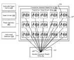
- FIG. 3is a block diagram of illustrating a portion of the phased array resonant power transmission system of FIG. 1 that is operable to calculate the location of the target device based on the received information to direct a magnetic field pattern in accordance with one or more embodiments of the present invention
- the power levelis the power level. After maximizing the magnetic field intensity at the magnetic focal point with respect to phase difference and direction, the field intensity can be further varied by the power level variation of the controlled power source 113 .
- the power from the controlled power source 113is fed to a power divider diving power equally into many ports with number of ports equal to the number of the coils.
- the power level for each of the tuned circuitis adjusted by a plurality of the power amplifiers providing the required power gain.
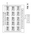
- two sinusoidal signals of same frequency from two tuned circuits of the receiver tuned circuit array 505 of FIG. 5such as tuned circuit- 1 signal 603 and tuned circuit- 2 signal 605 are combined in the power combiner 607 .
- the resulting output of the combination of the two signals 603 and 605is the sinusoidal signal 609 .
- the amplitude 611 of the signal 603is ideally the same as the amplitude 613 of the signal 605 .
- These signalsin general are magnetic field in the space (at the magnetic focal point) or the corresponding voltages at the two inputs of the power combiner.
- the amplitude of the resulting signal 609is 617 will be a maximum of the sum of the two amplitudes viz. 611 and 613 , only when the phases of the signals 603 and 605 are the same apart from their frequencies being the same.
- the angle between the fields linesalso matters during the vector addition.
Landscapes
- Engineering & Computer Science (AREA)
- Computer Networks & Wireless Communication (AREA)
- Power Engineering (AREA)
- Signal Processing (AREA)
- Charge And Discharge Circuits For Batteries Or The Like (AREA)
Abstract
Description
Claims (20)
Priority Applications (2)
| Application Number | Priority Date | Filing Date | Title |
|---|---|---|---|
| US12/241,279US7893564B2 (en) | 2008-08-05 | 2008-09-30 | Phased array wireless resonant power delivery system |
| US13/031,435US20110156493A1 (en) | 2008-08-05 | 2011-02-21 | Phased array wireless resonant power delivery system |
Applications Claiming Priority (2)
| Application Number | Priority Date | Filing Date | Title |
|---|---|---|---|
| US8638708P | 2008-08-05 | 2008-08-05 | |
| US12/241,279US7893564B2 (en) | 2008-08-05 | 2008-09-30 | Phased array wireless resonant power delivery system |
Related Child Applications (1)
| Application Number | Title | Priority Date | Filing Date |
|---|---|---|---|
| US13/031,435ContinuationUS20110156493A1 (en) | 2008-08-05 | 2011-02-21 | Phased array wireless resonant power delivery system |
Publications (2)
| Publication Number | Publication Date |
|---|---|
| US20100033021A1 US20100033021A1 (en) | 2010-02-11 |
| US7893564B2true US7893564B2 (en) | 2011-02-22 |
Family
ID=41652233
Family Applications (2)
| Application Number | Title | Priority Date | Filing Date |
|---|---|---|---|
| US12/241,279Active2029-09-30US7893564B2 (en) | 2008-08-05 | 2008-09-30 | Phased array wireless resonant power delivery system |
| US13/031,435AbandonedUS20110156493A1 (en) | 2008-08-05 | 2011-02-21 | Phased array wireless resonant power delivery system |
Family Applications After (1)
| Application Number | Title | Priority Date | Filing Date |
|---|---|---|---|
| US13/031,435AbandonedUS20110156493A1 (en) | 2008-08-05 | 2011-02-21 | Phased array wireless resonant power delivery system |
Country Status (1)
| Country | Link |
|---|---|
| US (2) | US7893564B2 (en) |
Cited By (50)
| Publication number | Priority date | Publication date | Assignee | Title |
|---|---|---|---|---|
| US20100289341A1 (en)* | 2009-02-10 | 2010-11-18 | Qualcomm Incorporated | Systems and methods relating to multi-dimensional wireless charging |
| US20110074346A1 (en)* | 2009-09-25 | 2011-03-31 | Hall Katherine L | Vehicle charger safety system and method |
| US20110156493A1 (en)* | 2008-08-05 | 2011-06-30 | Broadcom Corporation | Phased array wireless resonant power delivery system |
| US20120098485A1 (en)* | 2010-10-21 | 2012-04-26 | Samsung Electronics Co., Ltd. | Wireless charging method and apparatus |
| US20120126746A1 (en)* | 2010-11-23 | 2012-05-24 | Hon Hai Precision Industry Co., Ltd. | Wireless charging system |
| US20120169139A1 (en)* | 2009-12-24 | 2012-07-05 | Kabushiki Kaisha Toshiba | Wireless power transmission apparatus |
| US20120235500A1 (en)* | 2008-09-27 | 2012-09-20 | Ganem Steven J | Wireless energy distribution system |
| US20130069587A1 (en)* | 2010-11-30 | 2013-03-21 | Hanrim Postech Co., Ltd | Coil resonant coupler for short distance wireless power communication and short distance wireless power transmitting apparatus including the same |
| US20130252676A1 (en)* | 2012-03-26 | 2013-09-26 | Lg Innotek Co., Ltd. | Mobile terminal and power control method thereof |
| US20140184148A1 (en)* | 2012-12-28 | 2014-07-03 | Broadcom Corporation | Power Transfer Architecture With Charging History |
| TWI462424B (en)* | 2012-10-15 | 2014-11-21 | Panasonic Corp | Method of exciting primary coils in contactless power supply device and contactless power supply device |
| TWI469468B (en)* | 2011-08-25 | 2015-01-11 | Panasonic Corp | Method for detecting metal foreign object in contactless power supply system, contactless power supply device, power reception device, and contactless power supply system |
| US8933589B2 (en) | 2012-02-07 | 2015-01-13 | The Gillette Company | Wireless power transfer using separately tunable resonators |
| TWI470896B (en)* | 2011-10-14 | 2015-01-21 | Lg Innotek Co Ltd | Wireless power transmitter |
| TWI470897B (en)* | 2011-08-01 | 2015-01-21 | Panasonic Corp | Contactless power supply device |
| US20150042266A1 (en)* | 2013-08-12 | 2015-02-12 | Kuan-Wei Chen | Wireless charging device |
| US9030161B2 (en) | 2011-06-27 | 2015-05-12 | Board Of Regents, The University Of Texas System | Wireless power transmission |
| US20150207357A1 (en)* | 2014-01-23 | 2015-07-23 | Electronics And Telecommunications Research Institute | Wireless power transmission device, wireless power reception device and wireless power transmission system |
| US20150333536A1 (en)* | 2008-09-27 | 2015-11-19 | Witricity Corporation | Wireless energy distribution system |
| US9293251B2 (en) | 2012-10-11 | 2016-03-22 | Panasonic Intellectual Property Management Co., Ltd. | Method of exciting primary coils in contactless power supplying device and contactless power supplying device |
| US20160190855A1 (en)* | 2014-02-14 | 2016-06-30 | Massachusetts Institute Of Technology | Adaptive control of wireless power transfer |
| US9407106B2 (en) | 2012-04-03 | 2016-08-02 | Qualcomm Incorporated | System and method for wireless power control communication using bluetooth low energy |
| US9404954B2 (en) | 2012-10-19 | 2016-08-02 | Witricity Corporation | Foreign object detection in wireless energy transfer systems |
| US9442172B2 (en) | 2011-09-09 | 2016-09-13 | Witricity Corporation | Foreign object detection in wireless energy transfer systems |
| US20170179774A1 (en)* | 2015-12-16 | 2017-06-22 | Samsung Medison Co., Ltd. | Ultrasound probe and charging method thereof |
| US20170250561A1 (en)* | 2016-02-29 | 2017-08-31 | Beijing Xiaomi Mobile Software Co., Ltd. | System and Method for Wireless Charging |
| US9800076B2 (en) | 2014-02-14 | 2017-10-24 | Massachusetts Institute Of Technology | Wireless power transfer |
| US9871387B1 (en) | 2015-09-16 | 2018-01-16 | Energous Corporation | Systems and methods of object detection using one or more video cameras in wireless power charging systems |
| US9893538B1 (en) | 2015-09-16 | 2018-02-13 | Energous Corporation | Systems and methods of object detection in wireless power charging systems |
| US9991747B2 (en) | 2008-05-13 | 2018-06-05 | Qualcomm Incorporated | Signaling charging in wireless power environment |
| US10014733B2 (en) | 2014-08-28 | 2018-07-03 | Apple Inc. | Temperature management in a wireless energy transfer system |
| US20180205415A1 (en)* | 2015-09-17 | 2018-07-19 | Unist (Ulsan National Institute Of Science And Technology) | Communication System |
| US10110051B2 (en) | 2014-06-13 | 2018-10-23 | Apple Inc. | Detection of coil coupling in an inductive charging system |
| US20180307191A1 (en)* | 2015-10-06 | 2018-10-25 | Vega Grieshaber Kg | Modular field device having a display/operating device containing a radio module and an internal power supply |
| US10116279B2 (en) | 2014-02-23 | 2018-10-30 | Apple Inc. | Impedance matching for inductive power transfer systems |
| US10193372B2 (en) | 2014-09-02 | 2019-01-29 | Apple Inc. | Operating an inductive energy transfer system |
| US10199835B2 (en) | 2015-12-29 | 2019-02-05 | Energous Corporation | Radar motion detection using stepped frequency in wireless power transmission system |
| US10270261B2 (en) | 2015-09-16 | 2019-04-23 | Energous Corporation | Systems and methods of object detection in wireless power charging systems |
| US10291056B2 (en) | 2015-09-16 | 2019-05-14 | Energous Corporation | Systems and methods of controlling transmission of wireless power based on object indentification using a video camera |
| US10389274B2 (en) | 2017-04-07 | 2019-08-20 | Apple Inc. | Boosted output inverter for electronic devices |
| US10523063B2 (en) | 2017-04-07 | 2019-12-31 | Apple Inc. | Common mode noise compensation in wireless power systems |
| US10594159B2 (en) | 2014-06-03 | 2020-03-17 | Apple Inc. | Methods for detecting mated coils |
| US10644531B1 (en) | 2016-09-22 | 2020-05-05 | Apple Inc. | Adaptable power rectifier for wireless charger system |
| US10666084B2 (en) | 2015-07-10 | 2020-05-26 | Apple Inc. | Detection and notification of an unpowered releasable charging device |
| US10992159B2 (en) | 2014-12-31 | 2021-04-27 | Massachusetts Institute Of Technology | Adaptive control of wireless power transfer |
| US11050303B2 (en) | 2011-05-17 | 2021-06-29 | Samsung Electronics Co., Ltd. | Wireless charging apparatus and method |
| US11296557B2 (en) | 2017-05-30 | 2022-04-05 | Wireless Advanced Vehicle Electrification, Llc | Single feed multi-pad wireless charging |
| US11462943B2 (en) | 2018-01-30 | 2022-10-04 | Wireless Advanced Vehicle Electrification, Llc | DC link charging of capacitor in a wireless power transfer pad |
| US11942796B2 (en) | 2021-02-10 | 2024-03-26 | International Business Machines Corporation | Wireless power for sensor arrays |
| WO2025178982A1 (en)* | 2024-02-19 | 2025-08-28 | William Marsh Rice University | Methods of powering an implant when misaligned and transmitting data from the implant |
Families Citing this family (432)
| Publication number | Priority date | Publication date | Assignee | Title |
|---|---|---|---|---|
| US7825543B2 (en) | 2005-07-12 | 2010-11-02 | Massachusetts Institute Of Technology | Wireless energy transfer |
| US7928900B2 (en)* | 2006-12-15 | 2011-04-19 | Alliant Techsystems Inc. | Resolution antenna array using metamaterials |
| US9421388B2 (en) | 2007-06-01 | 2016-08-23 | Witricity Corporation | Power generation for implantable devices |
| US8115448B2 (en) | 2007-06-01 | 2012-02-14 | Michael Sasha John | Systems and methods for wireless power |
| US8446248B2 (en)* | 2007-06-14 | 2013-05-21 | Omnilectric, Inc. | Wireless power transmission system |
| US11264841B2 (en) | 2007-06-14 | 2022-03-01 | Ossia Inc. | Wireless power transmission system |
| US8159364B2 (en)* | 2007-06-14 | 2012-04-17 | Omnilectric, Inc. | Wireless power transmission system |
| US8855554B2 (en)* | 2008-03-05 | 2014-10-07 | Qualcomm Incorporated | Packaging and details of a wireless power device |
| US8878393B2 (en)* | 2008-05-13 | 2014-11-04 | Qualcomm Incorporated | Wireless power transfer for vehicles |
| CN102099958B (en) | 2008-05-14 | 2013-12-25 | 麻省理工学院 | Wireless power transfer including interference enhancement |
| US8987940B2 (en)* | 2008-08-15 | 2015-03-24 | Georgia Tech Research Corporation | Systems and methods for providing a power optimized waveform |
| US9106203B2 (en)* | 2008-09-27 | 2015-08-11 | Witricity Corporation | Secure wireless energy transfer in medical applications |
| US8957549B2 (en) | 2008-09-27 | 2015-02-17 | Witricity Corporation | Tunable wireless energy transfer for in-vehicle applications |
| US9744858B2 (en) | 2008-09-27 | 2017-08-29 | Witricity Corporation | System for wireless energy distribution in a vehicle |
| US8552592B2 (en)* | 2008-09-27 | 2013-10-08 | Witricity Corporation | Wireless energy transfer with feedback control for lighting applications |
| US9105959B2 (en) | 2008-09-27 | 2015-08-11 | Witricity Corporation | Resonator enclosure |
| US8643326B2 (en)* | 2008-09-27 | 2014-02-04 | Witricity Corporation | Tunable wireless energy transfer systems |
| EP3179640A1 (en)* | 2008-09-27 | 2017-06-14 | WiTricity Corporation | Wireless energy transfer systems |
| US8461721B2 (en) | 2008-09-27 | 2013-06-11 | Witricity Corporation | Wireless energy transfer using object positioning for low loss |
| US8946938B2 (en) | 2008-09-27 | 2015-02-03 | Witricity Corporation | Safety systems for wireless energy transfer in vehicle applications |
| US8901778B2 (en) | 2008-09-27 | 2014-12-02 | Witricity Corporation | Wireless energy transfer with variable size resonators for implanted medical devices |
| US8482158B2 (en) | 2008-09-27 | 2013-07-09 | Witricity Corporation | Wireless energy transfer using variable size resonators and system monitoring |
| US8461720B2 (en)* | 2008-09-27 | 2013-06-11 | Witricity Corporation | Wireless energy transfer using conducting surfaces to shape fields and reduce loss |
| US9601266B2 (en) | 2008-09-27 | 2017-03-21 | Witricity Corporation | Multiple connected resonators with a single electronic circuit |
| US8324759B2 (en)* | 2008-09-27 | 2012-12-04 | Witricity Corporation | Wireless energy transfer using magnetic materials to shape field and reduce loss |
| US8907531B2 (en) | 2008-09-27 | 2014-12-09 | Witricity Corporation | Wireless energy transfer with variable size resonators for medical applications |
| US8487480B1 (en) | 2008-09-27 | 2013-07-16 | Witricity Corporation | Wireless energy transfer resonator kit |
| US8441154B2 (en) | 2008-09-27 | 2013-05-14 | Witricity Corporation | Multi-resonator wireless energy transfer for exterior lighting |
| US8587155B2 (en)* | 2008-09-27 | 2013-11-19 | Witricity Corporation | Wireless energy transfer using repeater resonators |
| US9035499B2 (en) | 2008-09-27 | 2015-05-19 | Witricity Corporation | Wireless energy transfer for photovoltaic panels |
| US20100277121A1 (en)* | 2008-09-27 | 2010-11-04 | Hall Katherine L | Wireless energy transfer between a source and a vehicle |
| US8963488B2 (en) | 2008-09-27 | 2015-02-24 | Witricity Corporation | Position insensitive wireless charging |
| US8669676B2 (en) | 2008-09-27 | 2014-03-11 | Witricity Corporation | Wireless energy transfer across variable distances using field shaping with magnetic materials to improve the coupling factor |
| US8400017B2 (en) | 2008-09-27 | 2013-03-19 | Witricity Corporation | Wireless energy transfer for computer peripheral applications |
| US9544683B2 (en) | 2008-09-27 | 2017-01-10 | Witricity Corporation | Wirelessly powered audio devices |
| US9577436B2 (en) | 2008-09-27 | 2017-02-21 | Witricity Corporation | Wireless energy transfer for implantable devices |
| US8466583B2 (en) | 2008-09-27 | 2013-06-18 | Witricity Corporation | Tunable wireless energy transfer for outdoor lighting applications |
| US8933594B2 (en) | 2008-09-27 | 2015-01-13 | Witricity Corporation | Wireless energy transfer for vehicles |
| US9601261B2 (en) | 2008-09-27 | 2017-03-21 | Witricity Corporation | Wireless energy transfer using repeater resonators |
| US9515494B2 (en) | 2008-09-27 | 2016-12-06 | Witricity Corporation | Wireless power system including impedance matching network |
| US8912687B2 (en) | 2008-09-27 | 2014-12-16 | Witricity Corporation | Secure wireless energy transfer for vehicle applications |
| US8569914B2 (en) | 2008-09-27 | 2013-10-29 | Witricity Corporation | Wireless energy transfer using object positioning for improved k |
| US8901779B2 (en)* | 2008-09-27 | 2014-12-02 | Witricity Corporation | Wireless energy transfer with resonator arrays for medical applications |
| US8461722B2 (en) | 2008-09-27 | 2013-06-11 | Witricity Corporation | Wireless energy transfer using conducting surfaces to shape field and improve K |
| US20110043049A1 (en)* | 2008-09-27 | 2011-02-24 | Aristeidis Karalis | Wireless energy transfer with high-q resonators using field shaping to improve k |
| US9246336B2 (en) | 2008-09-27 | 2016-01-26 | Witricity Corporation | Resonator optimizations for wireless energy transfer |
| US8629578B2 (en) | 2008-09-27 | 2014-01-14 | Witricity Corporation | Wireless energy transfer systems |
| US9184595B2 (en) | 2008-09-27 | 2015-11-10 | Witricity Corporation | Wireless energy transfer in lossy environments |
| US8304935B2 (en)* | 2008-09-27 | 2012-11-06 | Witricity Corporation | Wireless energy transfer using field shaping to reduce loss |
| US9160203B2 (en) | 2008-09-27 | 2015-10-13 | Witricity Corporation | Wireless powered television |
| US8692412B2 (en)* | 2008-09-27 | 2014-04-08 | Witricity Corporation | Temperature compensation in a wireless transfer system |
| US8937408B2 (en) | 2008-09-27 | 2015-01-20 | Witricity Corporation | Wireless energy transfer for medical applications |
| US8476788B2 (en) | 2008-09-27 | 2013-07-02 | Witricity Corporation | Wireless energy transfer with high-Q resonators using field shaping to improve K |
| US9601270B2 (en) | 2008-09-27 | 2017-03-21 | Witricity Corporation | Low AC resistance conductor designs |
| US8587153B2 (en) | 2008-09-27 | 2013-11-19 | Witricity Corporation | Wireless energy transfer using high Q resonators for lighting applications |
| US9396867B2 (en) | 2008-09-27 | 2016-07-19 | Witricity Corporation | Integrated resonator-shield structures |
| US8686598B2 (en) | 2008-09-27 | 2014-04-01 | Witricity Corporation | Wireless energy transfer for supplying power and heat to a device |
| US8723366B2 (en) | 2008-09-27 | 2014-05-13 | Witricity Corporation | Wireless energy transfer resonator enclosures |
| US8497601B2 (en) | 2008-09-27 | 2013-07-30 | Witricity Corporation | Wireless energy transfer converters |
| US8947186B2 (en) | 2008-09-27 | 2015-02-03 | Witricity Corporation | Wireless energy transfer resonator thermal management |
| US8471410B2 (en) | 2008-09-27 | 2013-06-25 | Witricity Corporation | Wireless energy transfer over distance using field shaping to improve the coupling factor |
| US8410636B2 (en) | 2008-09-27 | 2013-04-02 | Witricity Corporation | Low AC resistance conductor designs |
| US8598743B2 (en) | 2008-09-27 | 2013-12-03 | Witricity Corporation | Resonator arrays for wireless energy transfer |
| US8772973B2 (en)* | 2008-09-27 | 2014-07-08 | Witricity Corporation | Integrated resonator-shield structures |
| US8922066B2 (en) | 2008-09-27 | 2014-12-30 | Witricity Corporation | Wireless energy transfer with multi resonator arrays for vehicle applications |
| US9093853B2 (en) | 2008-09-27 | 2015-07-28 | Witricity Corporation | Flexible resonator attachment |
| US8692410B2 (en)* | 2008-09-27 | 2014-04-08 | Witricity Corporation | Wireless energy transfer with frequency hopping |
| US9318922B2 (en) | 2008-09-27 | 2016-04-19 | Witricity Corporation | Mechanically removable wireless power vehicle seat assembly |
| US8928276B2 (en) | 2008-09-27 | 2015-01-06 | Witricity Corporation | Integrated repeaters for cell phone applications |
| US8362651B2 (en)* | 2008-10-01 | 2013-01-29 | Massachusetts Institute Of Technology | Efficient near-field wireless energy transfer using adiabatic system variations |
| US8497658B2 (en) | 2009-01-22 | 2013-07-30 | Qualcomm Incorporated | Adaptive power control for wireless charging of devices |
| US20100201312A1 (en) | 2009-02-10 | 2010-08-12 | Qualcomm Incorporated | Wireless power transfer for portable enclosures |
| US20100201311A1 (en)* | 2009-02-10 | 2010-08-12 | Qualcomm Incorporated | Wireless charging with separate process |
| US8854224B2 (en)* | 2009-02-10 | 2014-10-07 | Qualcomm Incorporated | Conveying device information relating to wireless charging |
| US20100201201A1 (en)* | 2009-02-10 | 2010-08-12 | Qualcomm Incorporated | Wireless power transfer in public places |
| JP5365276B2 (en)* | 2009-03-17 | 2013-12-11 | ソニー株式会社 | Power transmission system and power output device |
| JP5499534B2 (en)* | 2009-07-07 | 2014-05-21 | ソニー株式会社 | Non-contact power receiving apparatus, power receiving method in non-contact power receiving apparatus, and non-contact power feeding system |
| US20150255994A1 (en)* | 2009-09-25 | 2015-09-10 | Witricity Corporation | Safety systems for wireless energy transfer in vehicle applications |
| KR101197579B1 (en)* | 2009-11-04 | 2012-11-06 | 한국전기연구원 | Space-adaptive Wireless Power Transmission System and Method using Resonance of Evanescent Waves |
| KR101681055B1 (en)* | 2009-12-29 | 2016-11-30 | 삼성전자주식회사 | Resonance power receiver |
| JP2011147271A (en)* | 2010-01-14 | 2011-07-28 | Sony Corp | Power supply device, power receiving device, and wireless power supply system |
| US9024480B2 (en)* | 2010-01-27 | 2015-05-05 | Honeywell International Inc. | Controller for wireless energy transfer |
| US8823214B2 (en)* | 2010-01-27 | 2014-09-02 | Honeywell International Inc. | Wireless energy transfer |
| KR101104513B1 (en)* | 2010-02-16 | 2012-01-12 | 서울대학교산학협력단 | Multiple Wireless Power Transmission Method and System Using Time Division Method |
| JP2011200052A (en)* | 2010-03-23 | 2011-10-06 | Toyota Central R&D Labs Inc | Power supply device |
| US8674550B2 (en)* | 2010-03-25 | 2014-03-18 | General Electric Company | Contactless power transfer system and method |
| US8441153B2 (en)* | 2010-06-22 | 2013-05-14 | General Electric Company | Contactless power transfer system |
| JP5664015B2 (en)* | 2010-08-23 | 2015-02-04 | Tdk株式会社 | Coil device and non-contact power transmission device |
| KR101753607B1 (en) | 2010-08-24 | 2017-07-04 | 삼성전자주식회사 | Apparatus for radiational wireless power transmission and wireless power reception |
| US9602168B2 (en) | 2010-08-31 | 2017-03-21 | Witricity Corporation | Communication in wireless energy transfer systems |
| JP6094762B2 (en)* | 2010-09-14 | 2017-03-15 | ウィトリシティ コーポレーション | Wireless energy distribution system |
| KR101739293B1 (en)* | 2010-12-23 | 2017-05-24 | 삼성전자주식회사 | System for wireless power transmission and reception using in-band communication |
| US20120217817A1 (en)* | 2011-02-28 | 2012-08-30 | Bingnan Wang | Tuning Electromagnetic Fields Characteristics for Wireless Energy Transfer Using Arrays of Resonant Objects |
| CN103392285A (en)* | 2011-03-04 | 2013-11-13 | 叶军 | Vehicular non-contact battery charging apparatus |
| KR101859191B1 (en) | 2011-03-23 | 2018-05-18 | 삼성전자주식회사 | Method and apparatus for controlling wireless power transmission and reception, and wireless power transmission system |
| EP2518863A1 (en)* | 2011-04-27 | 2012-10-31 | Research In Motion Limited | Methods and apparatuses for wireless power transfer |
| KR101813129B1 (en) | 2011-05-04 | 2017-12-28 | 삼성전자주식회사 | Wireless power transmission and reception system |
| US9948145B2 (en) | 2011-07-08 | 2018-04-17 | Witricity Corporation | Wireless power transfer for a seat-vest-helmet system |
| CN108110907B (en) | 2011-08-04 | 2022-08-02 | 韦特里西提公司 | Tunable wireless power supply architecture |
| US10523276B2 (en)* | 2011-08-16 | 2019-12-31 | Qualcomm Incorporated | Wireless power receiver with multiple receiver coils |
| KR101844283B1 (en)* | 2011-08-18 | 2018-04-03 | 삼성전자주식회사 | A method and an apparatus for energy sharing of wireless communication device |
| KR101880030B1 (en) | 2011-08-25 | 2018-07-23 | 삼성전자주식회사 | Sauce apparatus and method that control magnetic field using two sauce resonators in Wireless Resonant Power Transfer system |
| EP2755300A4 (en)* | 2011-09-09 | 2015-04-22 | Chugoku Electric Power | Non-contact power supply system and non-contact power supply method |
| US20130062966A1 (en) | 2011-09-12 | 2013-03-14 | Witricity Corporation | Reconfigurable control architectures and algorithms for electric vehicle wireless energy transfer systems |
| US9577713B2 (en)* | 2011-09-29 | 2017-02-21 | Konica Minolta Laboratory U.S.A., Inc. | Method and system for aligning conductors for capacitive wireless power transmission |
| US9318257B2 (en) | 2011-10-18 | 2016-04-19 | Witricity Corporation | Wireless energy transfer for packaging |
| CA2853824A1 (en) | 2011-11-04 | 2013-05-10 | Witricity Corporation | Wireless energy transfer modeling tool |
| KR101338732B1 (en) | 2011-11-10 | 2013-12-06 | 엘지이노텍 주식회사 | Apparatus for transmmiting wireless power and apparatus for receiving wireless power and method for transmitting wireless power, method for receiving wireless power, method for transmitting information and method for receiving information |
| JP5849630B2 (en)* | 2011-11-14 | 2016-01-27 | 富士通株式会社 | Power repeater |
| US9079043B2 (en) | 2011-11-21 | 2015-07-14 | Thoratec Corporation | Transcutaneous power transmission utilizing non-planar resonators |
| SG190477A1 (en)* | 2011-11-28 | 2013-06-28 | Sony Corp | Wireless energy transfer system |
| JP5838768B2 (en)* | 2011-11-30 | 2016-01-06 | ソニー株式会社 | Sensing device, power receiving device, non-contact power transmission system, and sensing method |
| KR101667318B1 (en)* | 2011-12-27 | 2016-10-18 | 쥬코쿠 덴료쿠 가부시키 가이샤 | Wireless power transfer system, transmission device, and controlling method of wireless power transfer system |
| US9431856B2 (en)* | 2012-01-09 | 2016-08-30 | Pabellon, Inc. | Power transmission |
| JP2015508987A (en) | 2012-01-26 | 2015-03-23 | ワイトリシティ コーポレーションWitricity Corporation | Wireless energy transmission with reduced field |
| US20130300205A1 (en)* | 2012-05-09 | 2013-11-14 | Samsung Electronics Co., Ltd. | Method and apparatus for 3d orientation-free wireless power transfer |
| KR101789195B1 (en)* | 2012-05-16 | 2017-10-26 | 한국전자통신연구원 | Resonance coupling wireless energy transfer receiver and transmistter |
| US11621583B2 (en) | 2012-05-21 | 2023-04-04 | University Of Washington | Distributed control adaptive wireless power transfer system |
| US8827889B2 (en) | 2012-05-21 | 2014-09-09 | University Of Washington Through Its Center For Commercialization | Method and system for powering implantable devices |
| US9343922B2 (en) | 2012-06-27 | 2016-05-17 | Witricity Corporation | Wireless energy transfer for rechargeable batteries |
| JP5929563B2 (en)* | 2012-07-03 | 2016-06-08 | 三菱電機株式会社 | Wireless power feeding system, power transmitting device and power receiving device |
| US9893554B2 (en) | 2014-07-14 | 2018-02-13 | Energous Corporation | System and method for providing health safety in a wireless power transmission system |
| US10992187B2 (en) | 2012-07-06 | 2021-04-27 | Energous Corporation | System and methods of using electromagnetic waves to wirelessly deliver power to electronic devices |
| US20150326070A1 (en) | 2014-05-07 | 2015-11-12 | Energous Corporation | Methods and Systems for Maximum Power Point Transfer in Receivers |
| US9847677B1 (en) | 2013-10-10 | 2017-12-19 | Energous Corporation | Wireless charging and powering of healthcare gadgets and sensors |
| US9124125B2 (en)* | 2013-05-10 | 2015-09-01 | Energous Corporation | Wireless power transmission with selective range |
| US10063105B2 (en) | 2013-07-11 | 2018-08-28 | Energous Corporation | Proximity transmitters for wireless power charging systems |
| US10124754B1 (en) | 2013-07-19 | 2018-11-13 | Energous Corporation | Wireless charging and powering of electronic sensors in a vehicle |
| US10063064B1 (en) | 2014-05-23 | 2018-08-28 | Energous Corporation | System and method for generating a power receiver identifier in a wireless power network |
| US10075008B1 (en) | 2014-07-14 | 2018-09-11 | Energous Corporation | Systems and methods for manually adjusting when receiving electronic devices are scheduled to receive wirelessly delivered power from a wireless power transmitter in a wireless power network |
| US9368020B1 (en) | 2013-05-10 | 2016-06-14 | Energous Corporation | Off-premises alert system and method for wireless power receivers in a wireless power network |
| US9900057B2 (en) | 2012-07-06 | 2018-02-20 | Energous Corporation | Systems and methods for assigning groups of antenas of a wireless power transmitter to different wireless power receivers, and determining effective phases to use for wirelessly transmitting power using the assigned groups of antennas |
| US10128699B2 (en) | 2014-07-14 | 2018-11-13 | Energous Corporation | Systems and methods of providing wireless power using receiver device sensor inputs |
| US9876648B2 (en) | 2014-08-21 | 2018-01-23 | Energous Corporation | System and method to control a wireless power transmission system by configuration of wireless power transmission control parameters |
| US9876380B1 (en) | 2013-09-13 | 2018-01-23 | Energous Corporation | Secured wireless power distribution system |
| US9948135B2 (en) | 2015-09-22 | 2018-04-17 | Energous Corporation | Systems and methods for identifying sensitive objects in a wireless charging transmission field |
| US9871398B1 (en) | 2013-07-01 | 2018-01-16 | Energous Corporation | Hybrid charging method for wireless power transmission based on pocket-forming |
| US9867062B1 (en) | 2014-07-21 | 2018-01-09 | Energous Corporation | System and methods for using a remote server to authorize a receiving device that has requested wireless power and to determine whether another receiving device should request wireless power in a wireless power transmission system |
| US20150076927A1 (en)* | 2013-05-10 | 2015-03-19 | DvineWave Inc. | Wireless power supply for rescue devices |
| US9843213B2 (en) | 2013-08-06 | 2017-12-12 | Energous Corporation | Social power sharing for mobile devices based on pocket-forming |
| US10193396B1 (en) | 2014-05-07 | 2019-01-29 | Energous Corporation | Cluster management of transmitters in a wireless power transmission system |
| US9438045B1 (en) | 2013-05-10 | 2016-09-06 | Energous Corporation | Methods and systems for maximum power point transfer in receivers |
| US10211674B1 (en) | 2013-06-12 | 2019-02-19 | Energous Corporation | Wireless charging using selected reflectors |
| US9793758B2 (en)* | 2014-05-23 | 2017-10-17 | Energous Corporation | Enhanced transmitter using frequency control for wireless power transmission |
| US10218227B2 (en) | 2014-05-07 | 2019-02-26 | Energous Corporation | Compact PIFA antenna |
| US10141791B2 (en)* | 2014-05-07 | 2018-11-27 | Energous Corporation | Systems and methods for controlling communications during wireless transmission of power using application programming interfaces |
| US9939864B1 (en) | 2014-08-21 | 2018-04-10 | Energous Corporation | System and method to control a wireless power transmission system by configuration of wireless power transmission control parameters |
| US10186913B2 (en) | 2012-07-06 | 2019-01-22 | Energous Corporation | System and methods for pocket-forming based on constructive and destructive interferences to power one or more wireless power receivers using a wireless power transmitter including a plurality of antennas |
| US10224982B1 (en) | 2013-07-11 | 2019-03-05 | Energous Corporation | Wireless power transmitters for transmitting wireless power and tracking whether wireless power receivers are within authorized locations |
| US9887739B2 (en)* | 2012-07-06 | 2018-02-06 | Energous Corporation | Systems and methods for wireless power transmission by comparing voltage levels associated with power waves transmitted by antennas of a plurality of antennas of a transmitter to determine appropriate phase adjustments for the power waves |
| US10224758B2 (en) | 2013-05-10 | 2019-03-05 | Energous Corporation | Wireless powering of electronic devices with selective delivery range |
| US9859797B1 (en) | 2014-05-07 | 2018-01-02 | Energous Corporation | Synchronous rectifier design for wireless power receiver |
| US9876394B1 (en) | 2014-05-07 | 2018-01-23 | Energous Corporation | Boost-charger-boost system for enhanced power delivery |
| US9893555B1 (en) | 2013-10-10 | 2018-02-13 | Energous Corporation | Wireless charging of tools using a toolbox transmitter |
| US10063106B2 (en) | 2014-05-23 | 2018-08-28 | Energous Corporation | System and method for a self-system analysis in a wireless power transmission network |
| US9899861B1 (en) | 2013-10-10 | 2018-02-20 | Energous Corporation | Wireless charging methods and systems for game controllers, based on pocket-forming |
| US10206185B2 (en)* | 2013-05-10 | 2019-02-12 | Energous Corporation | System and methods for wireless power transmission to an electronic device in accordance with user-defined restrictions |
| US10291055B1 (en)* | 2014-12-29 | 2019-05-14 | Energous Corporation | Systems and methods for controlling far-field wireless power transmission based on battery power levels of a receiving device |
| US10256657B2 (en) | 2015-12-24 | 2019-04-09 | Energous Corporation | Antenna having coaxial structure for near field wireless power charging |
| US9891669B2 (en) | 2014-08-21 | 2018-02-13 | Energous Corporation | Systems and methods for a configuration web service to provide configuration of a wireless power transmitter within a wireless power transmission system |
| US9853692B1 (en) | 2014-05-23 | 2017-12-26 | Energous Corporation | Systems and methods for wireless power transmission |
| US9899873B2 (en) | 2014-05-23 | 2018-02-20 | Energous Corporation | System and method for generating a power receiver identifier in a wireless power network |
| US10381880B2 (en) | 2014-07-21 | 2019-08-13 | Energous Corporation | Integrated antenna structure arrays for wireless power transmission |
| US10050462B1 (en) | 2013-08-06 | 2018-08-14 | Energous Corporation | Social power sharing for mobile devices based on pocket-forming |
| US9825674B1 (en)* | 2014-05-23 | 2017-11-21 | Energous Corporation | Enhanced transmitter that selects configurations of antenna elements for performing wireless power transmission and receiving functions |
| US9991741B1 (en) | 2014-07-14 | 2018-06-05 | Energous Corporation | System for tracking and reporting status and usage information in a wireless power management system |
| US10965164B2 (en) | 2012-07-06 | 2021-03-30 | Energous Corporation | Systems and methods of wirelessly delivering power to a receiver device |
| US10263432B1 (en)* | 2013-06-25 | 2019-04-16 | Energous Corporation | Multi-mode transmitter with an antenna array for delivering wireless power and providing Wi-Fi access |
| US9923386B1 (en)* | 2012-07-06 | 2018-03-20 | Energous Corporation | Systems and methods for wireless power transmission by modifying a number of antenna elements used to transmit power waves to a receiver |
| US9973021B2 (en)* | 2012-07-06 | 2018-05-15 | Energous Corporation | Receivers for wireless power transmission |
| US20140008993A1 (en)* | 2012-07-06 | 2014-01-09 | DvineWave Inc. | Methodology for pocket-forming |
| US9876379B1 (en) | 2013-07-11 | 2018-01-23 | Energous Corporation | Wireless charging and powering of electronic devices in a vehicle |
| US10141768B2 (en) | 2013-06-03 | 2018-11-27 | Energous Corporation | Systems and methods for maximizing wireless power transfer efficiency by instructing a user to change a receiver device's position |
| US9843201B1 (en) | 2012-07-06 | 2017-12-12 | Energous Corporation | Wireless power transmitter that selects antenna sets for transmitting wireless power to a receiver based on location of the receiver, and methods of use thereof |
| US9966765B1 (en) | 2013-06-25 | 2018-05-08 | Energous Corporation | Multi-mode transmitter |
| US9831718B2 (en)* | 2013-07-25 | 2017-11-28 | Energous Corporation | TV with integrated wireless power transmitter |
| US9787103B1 (en) | 2013-08-06 | 2017-10-10 | Energous Corporation | Systems and methods for wirelessly delivering power to electronic devices that are unable to communicate with a transmitter |
| US9859757B1 (en)* | 2013-07-25 | 2018-01-02 | Energous Corporation | Antenna tile arrangements in electronic device enclosures |
| US9824815B2 (en) | 2013-05-10 | 2017-11-21 | Energous Corporation | Wireless charging and powering of healthcare gadgets and sensors |
| US9806564B2 (en) | 2014-05-07 | 2017-10-31 | Energous Corporation | Integrated rectifier and boost converter for wireless power transmission |
| US10103582B2 (en) | 2012-07-06 | 2018-10-16 | Energous Corporation | Transmitters for wireless power transmission |
| US9882427B2 (en) | 2013-05-10 | 2018-01-30 | Energous Corporation | Wireless power delivery using a base station to control operations of a plurality of wireless power transmitters |
| US10090886B1 (en) | 2014-07-14 | 2018-10-02 | Energous Corporation | System and method for enabling automatic charging schedules in a wireless power network to one or more devices |
| US10291066B1 (en) | 2014-05-07 | 2019-05-14 | Energous Corporation | Power transmission control systems and methods |
| US11502551B2 (en) | 2012-07-06 | 2022-11-15 | Energous Corporation | Wirelessly charging multiple wireless-power receivers using different subsets of an antenna array to focus energy at different locations |
| US9450449B1 (en) | 2012-07-06 | 2016-09-20 | Energous Corporation | Antenna arrangement for pocket-forming |
| US9847679B2 (en)* | 2014-05-07 | 2017-12-19 | Energous Corporation | System and method for controlling communication between wireless power transmitter managers |
| US10205239B1 (en) | 2014-05-07 | 2019-02-12 | Energous Corporation | Compact PIFA antenna |
| US9882430B1 (en) | 2014-05-07 | 2018-01-30 | Energous Corporation | Cluster management of transmitters in a wireless power transmission system |
| US9887584B1 (en) | 2014-08-21 | 2018-02-06 | Energous Corporation | Systems and methods for a configuration web service to provide configuration of a wireless power transmitter within a wireless power transmission system |
| US9912199B2 (en)* | 2012-07-06 | 2018-03-06 | Energous Corporation | Receivers for wireless power transmission |
| US9853458B1 (en) | 2014-05-07 | 2017-12-26 | Energous Corporation | Systems and methods for device and power receiver pairing |
| US10199849B1 (en) | 2014-08-21 | 2019-02-05 | Energous Corporation | Method for automatically testing the operational status of a wireless power receiver in a wireless power transmission system |
| US10230266B1 (en) | 2014-02-06 | 2019-03-12 | Energous Corporation | Wireless power receivers that communicate status data indicating wireless power transmission effectiveness with a transmitter using a built-in communications component of a mobile device, and methods of use thereof |
| US10148097B1 (en) | 2013-11-08 | 2018-12-04 | Energous Corporation | Systems and methods for using a predetermined number of communication channels of a wireless power transmitter to communicate with different wireless power receivers |
| US9893768B2 (en)* | 2012-07-06 | 2018-02-13 | Energous Corporation | Methodology for multiple pocket-forming |
| US10223717B1 (en) | 2014-05-23 | 2019-03-05 | Energous Corporation | Systems and methods for payment-based authorization of wireless power transmission service |
| US10128693B2 (en) | 2014-07-14 | 2018-11-13 | Energous Corporation | System and method for providing health safety in a wireless power transmission system |
| US9838083B2 (en) | 2014-07-21 | 2017-12-05 | Energous Corporation | Systems and methods for communication with remote management systems |
| US9143000B2 (en) | 2012-07-06 | 2015-09-22 | Energous Corporation | Portable wireless charging pad |
| US9954374B1 (en) | 2014-05-23 | 2018-04-24 | Energous Corporation | System and method for self-system analysis for detecting a fault in a wireless power transmission Network |
| US20140368048A1 (en)* | 2013-05-10 | 2014-12-18 | DvineWave Inc. | Wireless charging with reflectors |
| US10211680B2 (en)* | 2013-07-19 | 2019-02-19 | Energous Corporation | Method for 3 dimensional pocket-forming |
| US10090699B1 (en) | 2013-11-01 | 2018-10-02 | Energous Corporation | Wireless powered house |
| US10038337B1 (en)* | 2013-09-16 | 2018-07-31 | Energous Corporation | Wireless power supply for rescue devices |
| US10992185B2 (en) | 2012-07-06 | 2021-04-27 | Energous Corporation | Systems and methods of using electromagnetic waves to wirelessly deliver power to game controllers |
| US9859756B2 (en)* | 2012-07-06 | 2018-01-02 | Energous Corporation | Transmittersand methods for adjusting wireless power transmission based on information from receivers |
| US10243414B1 (en) | 2014-05-07 | 2019-03-26 | Energous Corporation | Wearable device with wireless power and payload receiver |
| US9812890B1 (en) | 2013-07-11 | 2017-11-07 | Energous Corporation | Portable wireless charging pad |
| US9252628B2 (en) | 2013-05-10 | 2016-02-02 | Energous Corporation | Laptop computer as a transmitter for wireless charging |
| US12057715B2 (en) | 2012-07-06 | 2024-08-06 | Energous Corporation | Systems and methods of wirelessly delivering power to a wireless-power receiver device in response to a change of orientation of the wireless-power receiver device |
| US10008889B2 (en) | 2014-08-21 | 2018-06-26 | Energous Corporation | Method for automatically testing the operational status of a wireless power receiver in a wireless power transmission system |
| US9941747B2 (en) | 2014-07-14 | 2018-04-10 | Energous Corporation | System and method for manually selecting and deselecting devices to charge in a wireless power network |
| US9906065B2 (en)* | 2012-07-06 | 2018-02-27 | Energous Corporation | Systems and methods of transmitting power transmission waves based on signals received at first and second subsets of a transmitter's antenna array |
| US10211682B2 (en)* | 2014-05-07 | 2019-02-19 | Energous Corporation | Systems and methods for controlling operation of a transmitter of a wireless power network based on user instructions received from an authenticated computing device powered or charged by a receiver of the wireless power network |
| US9941707B1 (en) | 2013-07-19 | 2018-04-10 | Energous Corporation | Home base station for multiple room coverage with multiple transmitters |
| US10439448B2 (en) | 2014-08-21 | 2019-10-08 | Energous Corporation | Systems and methods for automatically testing the communication between wireless power transmitter and wireless power receiver |
| US9941754B2 (en) | 2012-07-06 | 2018-04-10 | Energous Corporation | Wireless power transmission with selective range |
| US9130397B2 (en)* | 2013-05-10 | 2015-09-08 | Energous Corporation | Wireless charging and powering of electronic devices in a vehicle |
| US10383990B2 (en) | 2012-07-27 | 2019-08-20 | Tc1 Llc | Variable capacitor for resonant power transfer systems |
| US10291067B2 (en) | 2012-07-27 | 2019-05-14 | Tc1 Llc | Computer modeling for resonant power transfer systems |
| EP4257174A3 (en) | 2012-07-27 | 2023-12-27 | Tc1 Llc | Thermal management for implantable wireless power transfer systems |
| WO2014018973A1 (en) | 2012-07-27 | 2014-01-30 | Thoratec Corporation | Resonant power transmission coils and systems |
| WO2014018969A2 (en) | 2012-07-27 | 2014-01-30 | Thoratec Corporation | Resonant power transfer system and method of estimating system state |
| WO2014018974A1 (en)* | 2012-07-27 | 2014-01-30 | Thoratec Corporation | Magnetic power transmission utilizing phased transmitter coil arrays and phased receiver coil arrays |
| US9287040B2 (en) | 2012-07-27 | 2016-03-15 | Thoratec Corporation | Self-tuning resonant power transfer systems |
| WO2014018971A1 (en) | 2012-07-27 | 2014-01-30 | Thoratec Corporation | Resonant power transfer systems with protective algorithm |
| US9287607B2 (en) | 2012-07-31 | 2016-03-15 | Witricity Corporation | Resonator fine tuning |
| JP5626287B2 (en)* | 2012-08-02 | 2014-11-19 | トヨタ自動車株式会社 | Non-contact power transmission device, non-contact power reception device, vehicle and non-contact power transmission / reception system |
| US9595378B2 (en) | 2012-09-19 | 2017-03-14 | Witricity Corporation | Resonator enclosure |
| US9768643B2 (en) | 2012-11-02 | 2017-09-19 | Panasonic Intellectual Property Management Co., Ltd. | Wireless power transmission system capable of continuing power transmission while suppressing heatup of foreign objects |
| US11843260B2 (en) | 2012-11-09 | 2023-12-12 | California Institute Of Technology | Generator unit for wireless power transfer |
| CN104885333B (en) | 2012-11-09 | 2018-05-15 | 加州理工学院 | Smart RF Lensing: Efficient, Dynamic, and Mobile Wireless Power Transfer |
| US11616520B2 (en) | 2012-11-09 | 2023-03-28 | California Institute Of Technology | RF receiver |
| US9842684B2 (en) | 2012-11-16 | 2017-12-12 | Witricity Corporation | Systems and methods for wireless power system with improved performance and/or ease of use |
| EP2747195B1 (en)* | 2012-12-21 | 2017-02-08 | Stichting IMEC Nederland | Antenna arrangement for wireless powering |
| US9876535B2 (en) | 2013-02-21 | 2018-01-23 | Qualcomm Incorporated | Modular inductive power transfer power supply and method of operation |
| US9789236B2 (en) | 2013-03-14 | 2017-10-17 | Yale University | Implantable heart pump controller |
| WO2014145664A1 (en) | 2013-03-15 | 2014-09-18 | Thoratec Corporation | Integrated implantable tets housing including fins and coil loops |
| EP2984731B8 (en) | 2013-03-15 | 2019-06-26 | Tc1 Llc | Malleable tets coil with improved anatomical fit |
| US9866279B2 (en) | 2013-05-10 | 2018-01-09 | Energous Corporation | Systems and methods for selecting which power transmitter should deliver wireless power to a receiving device in a wireless power delivery network |
| US9419443B2 (en) | 2013-05-10 | 2016-08-16 | Energous Corporation | Transducer sound arrangement for pocket-forming |
| US9538382B2 (en) | 2013-05-10 | 2017-01-03 | Energous Corporation | System and method for smart registration of wireless power receivers in a wireless power network |
| US9819230B2 (en) | 2014-05-07 | 2017-11-14 | Energous Corporation | Enhanced receiver for wireless power transmission |
| US9537357B2 (en) | 2013-05-10 | 2017-01-03 | Energous Corporation | Wireless sound charging methods and systems for game controllers, based on pocket-forming |
| US9843763B2 (en) | 2013-05-10 | 2017-12-12 | Energous Corporation | TV system with wireless power transmitter |
| US10103552B1 (en)* | 2013-06-03 | 2018-10-16 | Energous Corporation | Protocols for authenticated wireless power transmission |
| US9900056B2 (en)* | 2013-06-14 | 2018-02-20 | Qualcomm Incorporated | System and method for delayed application processor initialization during wireless charging |
| US10003211B1 (en) | 2013-06-17 | 2018-06-19 | Energous Corporation | Battery life of portable electronic devices |
| US9521926B1 (en) | 2013-06-24 | 2016-12-20 | Energous Corporation | Wireless electrical temperature regulator for food and beverages |
| US10021523B2 (en) | 2013-07-11 | 2018-07-10 | Energous Corporation | Proximity transmitters for wireless power charging systems |
| US9979440B1 (en) | 2013-07-25 | 2018-05-22 | Energous Corporation | Antenna tile arrangements configured to operate as one functional unit |
| US9857821B2 (en) | 2013-08-14 | 2018-01-02 | Witricity Corporation | Wireless power transfer frequency adjustment |
| US10250072B2 (en)* | 2013-08-26 | 2019-04-02 | The University Of Hong Kong | Wireless power transfer system |
| US20150066155A1 (en)* | 2013-08-27 | 2015-03-05 | Freedom Innovations, Llc | Wireless charging for prosthetic device |
| EP3061176B1 (en)* | 2013-10-24 | 2020-11-11 | Harald Merkel | Method and arrangement for wireless energy transfer |
| EP3072210B1 (en) | 2013-11-11 | 2023-12-20 | Tc1 Llc | Resonant power transfer systems with communications |
| EP3069358B1 (en) | 2013-11-11 | 2019-06-12 | Tc1 Llc | Hinged resonant power transfer coil |
| US10695476B2 (en) | 2013-11-11 | 2020-06-30 | Tc1 Llc | Resonant power transfer systems with communications |
| EP3072214B1 (en)* | 2013-11-22 | 2018-10-10 | California Institute of Technology | Generator unit for wireless power transfer |
| CN105745816B (en) | 2013-11-22 | 2018-10-16 | 加州理工学院 | Active C MOS recovery units for wireless power transmission |
| US9780573B2 (en) | 2014-02-03 | 2017-10-03 | Witricity Corporation | Wirelessly charged battery system |
| US9935482B1 (en) | 2014-02-06 | 2018-04-03 | Energous Corporation | Wireless power transmitters that transmit at determined times based on power availability and consumption at a receiving mobile device |
| US10075017B2 (en) | 2014-02-06 | 2018-09-11 | Energous Corporation | External or internal wireless power receiver with spaced-apart antenna elements for charging or powering mobile devices using wirelessly delivered power |
| CN103795157B (en) | 2014-02-08 | 2016-03-23 | 北京智谷睿拓技术服务有限公司 | Wireless energy transfer method and wireless energy receiving equipment |
| US9952266B2 (en) | 2014-02-14 | 2018-04-24 | Witricity Corporation | Object detection for wireless energy transfer systems |
| WO2015125276A1 (en)* | 2014-02-21 | 2015-08-27 | 富士通株式会社 | Power transmission apparatus |
| WO2015134871A1 (en) | 2014-03-06 | 2015-09-11 | Thoratec Corporation | Electrical connectors for implantable devices |
| CN103872796B (en) | 2014-03-21 | 2016-09-28 | 北京智谷睿拓技术服务有限公司 | Wireless energy transfer method and detection equipment |
| US9892849B2 (en) | 2014-04-17 | 2018-02-13 | Witricity Corporation | Wireless power transfer systems with shield openings |
| US9842687B2 (en) | 2014-04-17 | 2017-12-12 | Witricity Corporation | Wireless power transfer systems with shaped magnetic components |
| EP3138183B1 (en)* | 2014-04-26 | 2019-08-21 | Elix Wireless Charging Systems Inc. | Magnetic field configuration for a wireless energy transfer system |
| US10158257B2 (en) | 2014-05-01 | 2018-12-18 | Energous Corporation | System and methods for using sound waves to wirelessly deliver power to electronic devices |
| US9966784B2 (en) | 2014-06-03 | 2018-05-08 | Energous Corporation | Systems and methods for extending battery life of portable electronic devices charged by sound |
| US9837860B2 (en) | 2014-05-05 | 2017-12-05 | Witricity Corporation | Wireless power transmission systems for elevators |
| US9973008B1 (en) | 2014-05-07 | 2018-05-15 | Energous Corporation | Wireless power receiver with boost converters directly coupled to a storage element |
| US10170917B1 (en) | 2014-05-07 | 2019-01-01 | Energous Corporation | Systems and methods for managing and controlling a wireless power network by establishing time intervals during which receivers communicate with a transmitter |
| JP2017518018A (en) | 2014-05-07 | 2017-06-29 | ワイトリシティ コーポレーションWitricity Corporation | Foreign object detection in wireless energy transmission systems |
| US10153653B1 (en) | 2014-05-07 | 2018-12-11 | Energous Corporation | Systems and methods for using application programming interfaces to control communications between a transmitter and a receiver |
| US9800172B1 (en) | 2014-05-07 | 2017-10-24 | Energous Corporation | Integrated rectifier and boost converter for boosting voltage received from wireless power transmission waves |
| US10153645B1 (en) | 2014-05-07 | 2018-12-11 | Energous Corporation | Systems and methods for designating a master power transmitter in a cluster of wireless power transmitters |
| KR20170003678A (en)* | 2014-05-13 | 2017-01-09 | 미쓰비시 덴끼 엔지니어링 가부시키가이샤 | Movable portion transmission system using wireless power transmission |
| US9876536B1 (en) | 2014-05-23 | 2018-01-23 | Energous Corporation | Systems and methods for assigning groups of antennas to transmit wireless power to different wireless power receivers |
| US9954375B2 (en) | 2014-06-20 | 2018-04-24 | Witricity Corporation | Wireless power transfer systems for surfaces |
| CN104090265B (en) | 2014-07-04 | 2016-10-05 | 北京智谷睿拓技术服务有限公司 | Localization method and equipment |
| CN107258046B (en) | 2014-07-08 | 2020-07-17 | 无线电力公司 | Resonator equalization in wireless power transfer systems |
| US10574091B2 (en) | 2014-07-08 | 2020-02-25 | Witricity Corporation | Enclosures for high power wireless power transfer systems |
| US10116143B1 (en) | 2014-07-21 | 2018-10-30 | Energous Corporation | Integrated antenna arrays for wireless power transmission |
| US9871301B2 (en) | 2014-07-21 | 2018-01-16 | Energous Corporation | Integrated miniature PIFA with artificial magnetic conductor metamaterials |
| US10068703B1 (en) | 2014-07-21 | 2018-09-04 | Energous Corporation | Integrated miniature PIFA with artificial magnetic conductor metamaterials |
| US10447092B2 (en) | 2014-07-31 | 2019-10-15 | Ossia Inc. | Techniques for determining distance between radiating objects in multipath wireless power delivery environments |
| EP3183797B1 (en) | 2014-08-19 | 2020-10-07 | California Institute of Technology | Wireless power transfer |
| US9917477B1 (en) | 2014-08-21 | 2018-03-13 | Energous Corporation | Systems and methods for automatically testing the communication between power transmitter and wireless receiver |
| US9965009B1 (en) | 2014-08-21 | 2018-05-08 | Energous Corporation | Systems and methods for assigning a power receiver to individual power transmitters based on location of the power receiver |
| EP3826104B1 (en) | 2014-09-22 | 2023-05-03 | Tc1 Llc | Antenna designs for communication between a wirelessly powered implant to an external device outside the body |
| US10811908B2 (en) | 2014-09-25 | 2020-10-20 | Supply, Inc. | System and method for wireless power reception |
| US10090707B2 (en) | 2014-09-25 | 2018-10-02 | Supply, Inc. | Wireless power transmission |
| WO2016057525A1 (en) | 2014-10-06 | 2016-04-14 | Thoratec Corporation | Multiaxial connector for implantable devices |
| WO2016069840A1 (en)* | 2014-10-31 | 2016-05-06 | Ossia Inc. | Techniques for filtering multi-component signals |
| US10122415B2 (en) | 2014-12-27 | 2018-11-06 | Energous Corporation | Systems and methods for assigning a set of antennas of a wireless power transmitter to a wireless power receiver based on a location of the wireless power receiver |
| JP6546282B2 (en)* | 2014-12-27 | 2019-07-17 | エナージャス コーポレイション | Method for three dimensional pocket formation |
| CN110289701B (en)* | 2014-12-29 | 2023-11-24 | 艾诺格思公司 | System and method for wireless power transfer |
| US9843217B2 (en) | 2015-01-05 | 2017-12-12 | Witricity Corporation | Wireless energy transfer for wearables |
| WO2016126167A1 (en)* | 2015-02-03 | 2016-08-11 | Powerbyproxi Limited | Inductive power transmitter |
| US9893535B2 (en) | 2015-02-13 | 2018-02-13 | Energous Corporation | Systems and methods for determining optimal charging positions to maximize efficiency of power received from wirelessly delivered sound wave energy |
| JP6312031B2 (en)* | 2015-04-02 | 2018-04-18 | パナソニックIpマネジメント株式会社 | Wireless power supply method |
| US10079494B2 (en)* | 2015-04-10 | 2018-09-18 | Ossia Inc. | Removably attachable portable device apparatus with integrated wireless power receiving facilities |
| US20160301238A1 (en)* | 2015-04-10 | 2016-10-13 | Intel Corporation | Managing presence and long beacon extension pulses |
| US10177607B2 (en) | 2015-04-10 | 2019-01-08 | Ossia Inc. | Techniques for delivering retrodirective wireless power |
| US9632554B2 (en) | 2015-04-10 | 2017-04-25 | Ossia Inc. | Calculating power consumption in wireless power delivery systems |
| US9620996B2 (en)* | 2015-04-10 | 2017-04-11 | Ossia Inc. | Wireless charging with multiple power receiving facilities on a wireless device |
| KR20160125048A (en)* | 2015-04-21 | 2016-10-31 | 엘지이노텍 주식회사 | Wireless power control method based on network, and apparatus and system thereof |
| US10224753B2 (en)* | 2015-05-27 | 2019-03-05 | Qualcomm Incorporated | Wireless power transfer using a field altering circuit |
| US9997963B2 (en) | 2015-06-08 | 2018-06-12 | Ossia Inc. | Techniques for scheduling delivery of wireless power in wireless power delivery environments |
| US10148126B2 (en) | 2015-08-31 | 2018-12-04 | Tc1 Llc | Wireless energy transfer system and wearables |
| US10523033B2 (en)* | 2015-09-15 | 2019-12-31 | Energous Corporation | Receiver devices configured to determine location within a transmission field |
| US9906275B2 (en)* | 2015-09-15 | 2018-02-27 | Energous Corporation | Identifying receivers in a wireless charging transmission field |
| US12283828B2 (en) | 2015-09-15 | 2025-04-22 | Energous Corporation | Receiver devices configured to determine location within a transmission field |
| US10186893B2 (en) | 2015-09-16 | 2019-01-22 | Energous Corporation | Systems and methods for real time or near real time wireless communications between a wireless power transmitter and a wireless power receiver |
| US10199850B2 (en) | 2015-09-16 | 2019-02-05 | Energous Corporation | Systems and methods for wirelessly transmitting power from a transmitter to a receiver by determining refined locations of the receiver in a segmented transmission field associated with the transmitter |
| US11710321B2 (en) | 2015-09-16 | 2023-07-25 | Energous Corporation | Systems and methods of object detection in wireless power charging systems |
| US10211685B2 (en) | 2015-09-16 | 2019-02-19 | Energous Corporation | Systems and methods for real or near real time wireless communications between a wireless power transmitter and a wireless power receiver |
| US10008875B1 (en) | 2015-09-16 | 2018-06-26 | Energous Corporation | Wireless power transmitter configured to transmit power waves to a predicted location of a moving wireless power receiver |
| US10158259B1 (en) | 2015-09-16 | 2018-12-18 | Energous Corporation | Systems and methods for identifying receivers in a transmission field by transmitting exploratory power waves towards different segments of a transmission field |
| US9941752B2 (en) | 2015-09-16 | 2018-04-10 | Energous Corporation | Systems and methods of object detection in wireless power charging systems |
| US10778041B2 (en) | 2015-09-16 | 2020-09-15 | Energous Corporation | Systems and methods for generating power waves in a wireless power transmission system |
| US10135294B1 (en) | 2015-09-22 | 2018-11-20 | Energous Corporation | Systems and methods for preconfiguring transmission devices for power wave transmissions based on location data of one or more receivers |
| US10153660B1 (en) | 2015-09-22 | 2018-12-11 | Energous Corporation | Systems and methods for preconfiguring sensor data for wireless charging systems |
| US10135295B2 (en)* | 2015-09-22 | 2018-11-20 | Energous Corporation | Systems and methods for nullifying energy levels for wireless power transmission waves |
| US10020678B1 (en) | 2015-09-22 | 2018-07-10 | Energous Corporation | Systems and methods for selecting antennas to generate and transmit power transmission waves |
| US10033222B1 (en) | 2015-09-22 | 2018-07-24 | Energous Corporation | Systems and methods for determining and generating a waveform for wireless power transmission waves |
| US10128686B1 (en) | 2015-09-22 | 2018-11-13 | Energous Corporation | Systems and methods for identifying receiver locations using sensor technologies |
| US10027168B2 (en)* | 2015-09-22 | 2018-07-17 | Energous Corporation | Systems and methods for generating and transmitting wireless power transmission waves using antennas having a spacing that is selected by the transmitter |
| US10050470B1 (en) | 2015-09-22 | 2018-08-14 | Energous Corporation | Wireless power transmission device having antennas oriented in three dimensions |
| US10164469B1 (en)* | 2015-09-28 | 2018-12-25 | Apple Inc. | Adaptive wireless power transfer system |
| US10248899B2 (en) | 2015-10-06 | 2019-04-02 | Witricity Corporation | RFID tag and transponder detection in wireless energy transfer systems |
| WO2017062552A1 (en) | 2015-10-07 | 2017-04-13 | Tc1 Llc | Resonant power transfer systems having efficiency optimization based on receiver impedance |
| US10333332B1 (en) | 2015-10-13 | 2019-06-25 | Energous Corporation | Cross-polarized dipole antenna |
| US10734717B2 (en) | 2015-10-13 | 2020-08-04 | Energous Corporation | 3D ceramic mold antenna |
| US9929721B2 (en) | 2015-10-14 | 2018-03-27 | Witricity Corporation | Phase and amplitude detection in wireless energy transfer systems |
| JP2018536372A (en) | 2015-10-15 | 2018-12-06 | オシア,インク. | Concentration method of pulsed transmission in multipath wireless power supply environment |
| WO2017070227A1 (en) | 2015-10-19 | 2017-04-27 | Witricity Corporation | Foreign object detection in wireless energy transfer systems |
| WO2017070009A1 (en) | 2015-10-22 | 2017-04-27 | Witricity Corporation | Dynamic tuning in wireless energy transfer systems |
| US9853485B2 (en) | 2015-10-28 | 2017-12-26 | Energous Corporation | Antenna for wireless charging systems |
| US9899744B1 (en) | 2015-10-28 | 2018-02-20 | Energous Corporation | Antenna for wireless charging systems |
| US10027180B1 (en) | 2015-11-02 | 2018-07-17 | Energous Corporation | 3D triple linear antenna that acts as heat sink |
| US10135112B1 (en) | 2015-11-02 | 2018-11-20 | Energous Corporation | 3D antenna mount |
| US10063108B1 (en) | 2015-11-02 | 2018-08-28 | Energous Corporation | Stamped three-dimensional antenna |
| US10075019B2 (en) | 2015-11-20 | 2018-09-11 | Witricity Corporation | Voltage source isolation in wireless power transfer systems |
| CN105529770B (en)* | 2015-12-22 | 2018-07-27 | 惠州市雨林科技有限公司 | A kind of onboard wireless charging system |
| US10079515B2 (en) | 2016-12-12 | 2018-09-18 | Energous Corporation | Near-field RF charging pad with multi-band antenna element with adaptive loading to efficiently charge an electronic device at any position on the pad |
| US10256677B2 (en) | 2016-12-12 | 2019-04-09 | Energous Corporation | Near-field RF charging pad with adaptive loading to efficiently charge an electronic device at any position on the pad |
| US10027159B2 (en) | 2015-12-24 | 2018-07-17 | Energous Corporation | Antenna for transmitting wireless power signals |
| US11863001B2 (en) | 2015-12-24 | 2024-01-02 | Energous Corporation | Near-field antenna for wireless power transmission with antenna elements that follow meandering patterns |
| US10116162B2 (en) | 2015-12-24 | 2018-10-30 | Energous Corporation | Near field transmitters with harmonic filters for wireless power charging |
| US10320446B2 (en) | 2015-12-24 | 2019-06-11 | Energous Corporation | Miniaturized highly-efficient designs for near-field power transfer system |
| US10038332B1 (en) | 2015-12-24 | 2018-07-31 | Energous Corporation | Systems and methods of wireless power charging through multiple receiving devices |
| US10008886B2 (en) | 2015-12-29 | 2018-06-26 | Energous Corporation | Modular antennas with heat sinks in wireless power transmission systems |
| WO2017136491A1 (en) | 2016-02-02 | 2017-08-10 | Witricity Corporation | Controlling wireless power transfer systems |
| CN114123540B (en) | 2016-02-08 | 2024-08-20 | 韦特里西提公司 | Variable capacitance device and high-power wireless energy transmission system |
| US11043988B2 (en) | 2016-03-15 | 2021-06-22 | Verily Life Sciences LLP | Systems for providing wireless power to deep implanted devices |
| KR102601601B1 (en) | 2016-04-19 | 2023-11-13 | 삼성전자주식회사 | Wireless Power Transceiver using phase and amplitude control algorithm and wireless power receiver |
| US10536041B2 (en)* | 2016-07-13 | 2020-01-14 | Comcast Cable Communications, Llc | System and method for wireless intercommunication and power delivery |
| US11309744B2 (en)* | 2016-09-11 | 2022-04-19 | Verily Life Sciences Llc | Systems and methods for providing wireless power to deep implanted devices |
| KR102572578B1 (en)* | 2016-09-19 | 2023-09-01 | 삼성전자주식회사 | Wireless power transmitter and method for controlling thereof |
| EP4084271A1 (en) | 2016-09-21 | 2022-11-02 | Tc1 Llc | Systems and methods for locating implanted wireless power transmission devices |
| US10923954B2 (en) | 2016-11-03 | 2021-02-16 | Energous Corporation | Wireless power receiver with a synchronous rectifier |
| WO2018106762A1 (en)* | 2016-12-11 | 2018-06-14 | Apple Inc. | Multi-transmitter wireless power systems |
| KR102185600B1 (en) | 2016-12-12 | 2020-12-03 | 에너저스 코포레이션 | A method of selectively activating antenna zones of a near field charging pad to maximize transmitted wireless power |
| KR102623589B1 (en) | 2016-12-23 | 2024-01-11 | 삼성전자주식회사 | Wireless power transmitter, electronic device and method for controlling thereof |
| US10680319B2 (en) | 2017-01-06 | 2020-06-09 | Energous Corporation | Devices and methods for reducing mutual coupling effects in wireless power transmission systems |
| US10439442B2 (en) | 2017-01-24 | 2019-10-08 | Energous Corporation | Microstrip antennas for wireless power transmitters |
| US10389161B2 (en) | 2017-03-15 | 2019-08-20 | Energous Corporation | Surface mount dielectric antennas for wireless power transmitters |
| WO2018136592A2 (en) | 2017-01-18 | 2018-07-26 | Tc1 Llc | Systems and methods for transcutaneous power transfer using microneedles |
| US11011942B2 (en) | 2017-03-30 | 2021-05-18 | Energous Corporation | Flat antennas having two or more resonant frequencies for use in wireless power transmission systems |
| KR20180117394A (en)* | 2017-04-19 | 2018-10-29 | 재단법인 다차원 스마트 아이티 융합시스템 연구단 | Wireless charging system for using frequency control |
| US10511097B2 (en) | 2017-05-12 | 2019-12-17 | Energous Corporation | Near-field antennas for accumulating energy at a near-field distance with minimal far-field gain |
| US12074460B2 (en) | 2017-05-16 | 2024-08-27 | Wireless Electrical Grid Lan, Wigl Inc. | Rechargeable wireless power bank and method of using |
| US11462949B2 (en) | 2017-05-16 | 2022-10-04 | Wireless electrical Grid LAN, WiGL Inc | Wireless charging method and system |
| US12074452B2 (en) | 2017-05-16 | 2024-08-27 | Wireless Electrical Grid Lan, Wigl Inc. | Networked wireless charging system |
| WO2018218252A1 (en) | 2017-05-26 | 2018-11-29 | California Institute Of Technology | Method and apparatus for dynamic rf lens focusing and tracking of wireless power recovery unit |
| US10798665B2 (en) | 2017-06-06 | 2020-10-06 | Supply, Inc. | Method and system for wireless power delivery |
| US11178625B2 (en) | 2017-06-06 | 2021-11-16 | Supply, Inc. | Method and system for wireless power delivery |
| WO2018226871A1 (en) | 2017-06-06 | 2018-12-13 | Supply, Inc. | Method and system for wireless power delivery |
| US10848853B2 (en) | 2017-06-23 | 2020-11-24 | Energous Corporation | Systems, methods, and devices for utilizing a wire of a sound-producing device as an antenna for receipt of wirelessly delivered power |
| WO2019006376A1 (en) | 2017-06-29 | 2019-01-03 | Witricity Corporation | Protection and control of wireless power systems |
| US10855110B2 (en)* | 2017-09-06 | 2020-12-01 | Apple Inc. | Antenna integration for portable electronic devices having wireless charging receiver systems |
| US10381881B2 (en) | 2017-09-06 | 2019-08-13 | Apple Inc. | Architecture of portable electronic devices with wireless charging receiver systems |
| US11426091B2 (en) | 2017-09-06 | 2022-08-30 | Apple Inc. | Film coatings as electrically conductive pathways |
| US11476717B2 (en) | 2017-09-29 | 2022-10-18 | Hewlett-Packard Development Company, L.P. | Transmission of wireless power |
| US10122219B1 (en) | 2017-10-10 | 2018-11-06 | Energous Corporation | Systems, methods, and devices for using a battery as a antenna for receiving wirelessly delivered power from radio frequency power waves |
| US11342798B2 (en) | 2017-10-30 | 2022-05-24 | Energous Corporation | Systems and methods for managing coexistence of wireless-power signals and data signals operating in a same frequency band |
| US10418861B2 (en) | 2017-12-22 | 2019-09-17 | Ossia Inc. | Transmission path identification based on propagation channel diversity |
| CN111758204B (en)* | 2017-12-22 | 2021-10-19 | 欧希亚有限公司 | Transmission Path Identification Based on Propagation Channel Diversity |
| WO2019135890A1 (en) | 2018-01-04 | 2019-07-11 | Tc1 Llc | Systems and methods for elastic wireless power transmission devices |
| US10615647B2 (en) | 2018-02-02 | 2020-04-07 | Energous Corporation | Systems and methods for detecting wireless power receivers and other objects at a near-field charging pad |
| JP2019154195A (en)* | 2018-03-06 | 2019-09-12 | 株式会社東芝 | Electronic device and power feeding method |
| EP3763015A4 (en) | 2018-03-08 | 2021-12-29 | Supply, Inc. | Method and system for wireless power delivery |
| JP6770545B2 (en)* | 2018-03-13 | 2020-10-14 | 株式会社東芝 | Transmission equipment and power transmission system |
| US11159057B2 (en) | 2018-03-14 | 2021-10-26 | Energous Corporation | Loop antennas with selectively-activated feeds to control propagation patterns of wireless power signals |
| CN108682970A (en)* | 2018-05-03 | 2018-10-19 | 苏州威斯东山电子技术有限公司 | High-gain and high-power radio-frequency sending coil module suitable for long distance wireless charging |
| US11515732B2 (en) | 2018-06-25 | 2022-11-29 | Energous Corporation | Power wave transmission techniques to focus wirelessly delivered power at a receiving device |
| CN110707828A (en)* | 2018-07-09 | 2020-01-17 | 中兴通讯股份有限公司 | Wireless charging receiving device, wireless charging implementation method and mobile terminal |
| KR102607259B1 (en)* | 2018-08-23 | 2023-11-29 | 삼성전자주식회사 | Wireless power transmitter, electronic device wirelessly receiving power and method for controlling thereof |
| US11437735B2 (en) | 2018-11-14 | 2022-09-06 | Energous Corporation | Systems for receiving electromagnetic energy using antennas that are minimally affected by the presence of the human body |
| KR102327580B1 (en)* | 2018-11-16 | 2021-11-17 | 한국과학기술원 | Wireless power transmit apparatus |
| US10820283B2 (en) | 2018-11-28 | 2020-10-27 | Supply, Inc. | System and method for wireless power delivery |
| WO2020113046A1 (en) | 2018-11-30 | 2020-06-04 | Supply, Inc. | Methods and systems for multi-objective optimization and/or wireless power delivery |
| US11394248B2 (en) | 2018-11-30 | 2022-07-19 | Ossia Inc. | Distributed wireless power transmission system |
| US11539243B2 (en) | 2019-01-28 | 2022-12-27 | Energous Corporation | Systems and methods for miniaturized antenna for wireless power transmissions |
| EP3921945A1 (en) | 2019-02-06 | 2021-12-15 | Energous Corporation | Systems and methods of estimating optimal phases to use for individual antennas in an antenna array |
| US12155231B2 (en) | 2019-04-09 | 2024-11-26 | Energous Corporation | Asymmetric spiral antennas for wireless power transmission and reception |
| EP3954019A4 (en) | 2019-04-10 | 2023-02-15 | Ossia Inc. | Simplified wireless power receiver architecture |
| WO2021055899A1 (en) | 2019-09-20 | 2021-03-25 | Energous Corporation | Systems and methods of protecting wireless power receivers using multiple rectifiers and establishing in-band communications using multiple rectifiers |
| WO2021055901A1 (en) | 2019-09-20 | 2021-03-25 | Energous Corporation | Asymmetric spiral antennas with parasitic elements for wireless power transmission |
| WO2021055898A1 (en) | 2019-09-20 | 2021-03-25 | Energous Corporation | Systems and methods for machine learning based foreign object detection for wireless power transmission |
| US11381118B2 (en) | 2019-09-20 | 2022-07-05 | Energous Corporation | Systems and methods for machine learning based foreign object detection for wireless power transmission |
| CN114731061A (en) | 2019-09-20 | 2022-07-08 | 艾诺格思公司 | Classifying and detecting foreign objects using a power amplifier controller integrated circuit in a wireless power transmission system |
| US11355966B2 (en) | 2019-12-13 | 2022-06-07 | Energous Corporation | Charging pad with guiding contours to align an electronic device on the charging pad and efficiently transfer near-field radio-frequency energy to the electronic device |
| US10985617B1 (en) | 2019-12-31 | 2021-04-20 | Energous Corporation | System for wirelessly transmitting energy at a near-field distance without using beam-forming control |
| GB202000370D0 (en)* | 2020-01-10 | 2020-02-26 | Metaboards Ltd | Electrical resonators |
| KR102755588B1 (en) | 2020-02-03 | 2025-01-15 | 보스톤 싸이엔티픽 싸이메드 인코포레이티드 | Stent, mandrel, and method for forming a stent with anti-migration features |
| US11799324B2 (en) | 2020-04-13 | 2023-10-24 | Energous Corporation | Wireless-power transmitting device for creating a uniform near-field charging area |
| US11469629B2 (en) | 2020-08-12 | 2022-10-11 | Energous Corporation | Systems and methods for secure wireless transmission of power using unidirectional communication signals from a wireless-power-receiving device |
| US20220052565A1 (en)* | 2020-08-15 | 2022-02-17 | Aira, Inc. | Resonant Reflection Device Detection |
| US12306285B2 (en) | 2020-12-01 | 2025-05-20 | Energous Corporation | Systems and methods for using one or more sensors to detect and classify objects in a keep-out zone of a wireless-power transmission field, and antennas with integrated sensor arrangements |
| EP4016798B1 (en)* | 2020-12-17 | 2025-09-17 | Stichting IMEC Nederland | A powering apparatus for wireless powering and a method for controlling a powering apparatus |
| US11611242B2 (en) | 2021-04-14 | 2023-03-21 | Reach Power, Inc. | System and method for wireless power networking |
| US11916398B2 (en) | 2021-12-29 | 2024-02-27 | Energous Corporation | Small form-factor devices with integrated and modular harvesting receivers, and shelving-mounted wireless-power transmitters for use therewith |
| US12142939B2 (en) | 2022-05-13 | 2024-11-12 | Energous Corporation | Integrated wireless-power-transmission platform designed to operate in multiple bands, and multi-band antennas for use therewith |
| DE102022117002A1 (en) | 2022-07-07 | 2024-01-18 | Maag Germany Gmbh | Granulator |
| GB2621546A (en)* | 2022-07-22 | 2024-02-21 | Univ Leeds Innovations Ltd | A system for powering a device and method of the same |
Citations (4)
| Publication number | Priority date | Publication date | Assignee | Title |
|---|---|---|---|---|
| US6570541B2 (en)* | 1998-05-18 | 2003-05-27 | Db Tag, Inc. | Systems and methods for wirelessly projecting power using multiple in-phase current loops |
| US20070182367A1 (en)* | 2006-01-31 | 2007-08-09 | Afshin Partovi | Inductive power source and charging system |
| US20080116847A1 (en)* | 2006-09-01 | 2008-05-22 | Bio Aim Technologies Holding Ltd. | Systems and methods for wireless power transfer |
| US7521890B2 (en)* | 2005-12-27 | 2009-04-21 | Power Science Inc. | System and method for selective transfer of radio frequency power |
Family Cites Families (14)
| Publication number | Priority date | Publication date | Assignee | Title |
|---|---|---|---|---|
| US7212414B2 (en)* | 1999-06-21 | 2007-05-01 | Access Business Group International, Llc | Adaptive inductive power supply |
| GB2388716B (en)* | 2002-05-13 | 2004-10-20 | Splashpower Ltd | Improvements relating to contact-less power transfer |
| EP2479866B1 (en)* | 2002-06-10 | 2018-07-18 | City University of Hong Kong | Planar inductive battery charger |
| US7233137B2 (en)* | 2003-09-30 | 2007-06-19 | Sharp Kabushiki Kaisha | Power supply system |
| JP4036813B2 (en)* | 2003-09-30 | 2008-01-23 | シャープ株式会社 | Non-contact power supply system |
| US7825543B2 (en)* | 2005-07-12 | 2010-11-02 | Massachusetts Institute Of Technology | Wireless energy transfer |
| KR100819604B1 (en)* | 2005-07-27 | 2008-04-03 | 엘에스전선 주식회사 | Wireless Charger Decreased in Variation of Charging Efficiency |
| US8169185B2 (en)* | 2006-01-31 | 2012-05-01 | Mojo Mobility, Inc. | System and method for inductive charging of portable devices |
| CN101802942A (en)* | 2007-01-29 | 2010-08-11 | 普迈公司 | Pinless power coupling |
| EP3975372B1 (en)* | 2007-03-22 | 2024-01-31 | Powermat Technologies Ltd. | Efficiency monitor for inductive power transmission |
| US9634730B2 (en)* | 2007-07-09 | 2017-04-25 | Qualcomm Incorporated | Wireless energy transfer using coupled antennas |
| US8338990B2 (en)* | 2008-03-13 | 2012-12-25 | Access Business Group International Llc | Inductive power supply system with multiple coil primary |
| US7893564B2 (en)* | 2008-08-05 | 2011-02-22 | Broadcom Corporation | Phased array wireless resonant power delivery system |
| US8598743B2 (en)* | 2008-09-27 | 2013-12-03 | Witricity Corporation | Resonator arrays for wireless energy transfer |
- 2008
- 2008-09-30USUS12/241,279patent/US7893564B2/enactiveActive
- 2011
- 2011-02-21USUS13/031,435patent/US20110156493A1/ennot_activeAbandoned
Patent Citations (4)
| Publication number | Priority date | Publication date | Assignee | Title |
|---|---|---|---|---|
| US6570541B2 (en)* | 1998-05-18 | 2003-05-27 | Db Tag, Inc. | Systems and methods for wirelessly projecting power using multiple in-phase current loops |
| US7521890B2 (en)* | 2005-12-27 | 2009-04-21 | Power Science Inc. | System and method for selective transfer of radio frequency power |
| US20070182367A1 (en)* | 2006-01-31 | 2007-08-09 | Afshin Partovi | Inductive power source and charging system |
| US20080116847A1 (en)* | 2006-09-01 | 2008-05-22 | Bio Aim Technologies Holding Ltd. | Systems and methods for wireless power transfer |
Cited By (82)
| Publication number | Priority date | Publication date | Assignee | Title |
|---|---|---|---|---|
| US9991747B2 (en) | 2008-05-13 | 2018-06-05 | Qualcomm Incorporated | Signaling charging in wireless power environment |
| US20110156493A1 (en)* | 2008-08-05 | 2011-06-30 | Broadcom Corporation | Phased array wireless resonant power delivery system |
| US20120235500A1 (en)* | 2008-09-27 | 2012-09-20 | Ganem Steven J | Wireless energy distribution system |
| US20150333536A1 (en)* | 2008-09-27 | 2015-11-19 | Witricity Corporation | Wireless energy distribution system |
| US9065423B2 (en)* | 2008-09-27 | 2015-06-23 | Witricity Corporation | Wireless energy distribution system |
| US9312924B2 (en)* | 2009-02-10 | 2016-04-12 | Qualcomm Incorporated | Systems and methods relating to multi-dimensional wireless charging |
| US20100289341A1 (en)* | 2009-02-10 | 2010-11-18 | Qualcomm Incorporated | Systems and methods relating to multi-dimensional wireless charging |
| US20110074346A1 (en)* | 2009-09-25 | 2011-03-31 | Hall Katherine L | Vehicle charger safety system and method |
| US20120169139A1 (en)* | 2009-12-24 | 2012-07-05 | Kabushiki Kaisha Toshiba | Wireless power transmission apparatus |
| US20120098485A1 (en)* | 2010-10-21 | 2012-04-26 | Samsung Electronics Co., Ltd. | Wireless charging method and apparatus |
| US9059598B2 (en)* | 2010-10-21 | 2015-06-16 | Samsung Electronics Co., Ltd | Wireless charging method and apparatus |
| US8513916B2 (en)* | 2010-11-23 | 2013-08-20 | Hong Fu Jin Precision Industry (Shenzhen) Co., Ltd. | Wireless charging system |
| US20120126746A1 (en)* | 2010-11-23 | 2012-05-24 | Hon Hai Precision Industry Co., Ltd. | Wireless charging system |
| US20130069587A1 (en)* | 2010-11-30 | 2013-03-21 | Hanrim Postech Co., Ltd | Coil resonant coupler for short distance wireless power communication and short distance wireless power transmitting apparatus including the same |
| US9577447B2 (en)* | 2010-11-30 | 2017-02-21 | Hanrim Postech Co., Ltd. | Short distance wireless power transmitting apparatus which enchances wireless power transmitting capability regardless of a relative arrangment with respect to a wireless power receiving apparatus |
| US11056932B2 (en) | 2011-05-17 | 2021-07-06 | Samsung Electronics Co., Ltd. | Wireless charging apparatus and method |
| US11050303B2 (en) | 2011-05-17 | 2021-06-29 | Samsung Electronics Co., Ltd. | Wireless charging apparatus and method |
| US9030161B2 (en) | 2011-06-27 | 2015-05-12 | Board Of Regents, The University Of Texas System | Wireless power transmission |
| TWI470897B (en)* | 2011-08-01 | 2015-01-21 | Panasonic Corp | Contactless power supply device |
| US9275790B2 (en) | 2011-08-01 | 2016-03-01 | Panasonic Intellectual Property Management Co., Ltd. | Contactless power supplying device |
| US9177716B2 (en) | 2011-08-25 | 2015-11-03 | Panasonic Intellectual Property Management Co., Ltd. | Method for detecting metal foreign object in contactless power supply system, contactless power supply device, power reception device, and contactless power supply system |
| TWI469468B (en)* | 2011-08-25 | 2015-01-11 | Panasonic Corp | Method for detecting metal foreign object in contactless power supply system, contactless power supply device, power reception device, and contactless power supply system |
| US10027184B2 (en) | 2011-09-09 | 2018-07-17 | Witricity Corporation | Foreign object detection in wireless energy transfer systems |
| US9442172B2 (en) | 2011-09-09 | 2016-09-13 | Witricity Corporation | Foreign object detection in wireless energy transfer systems |
| US10778047B2 (en) | 2011-09-09 | 2020-09-15 | Witricity Corporation | Foreign object detection in wireless energy transfer systems |
| US9923388B2 (en)* | 2011-10-14 | 2018-03-20 | Lg Innotek Co., Ltd. | Wireless power transmitter |
| US9300366B2 (en) | 2011-10-14 | 2016-03-29 | Lg Innotek Co., Ltd. | Wireless power transmitter |
| TWI470896B (en)* | 2011-10-14 | 2015-01-21 | Lg Innotek Co Ltd | Wireless power transmitter |
| US9634495B2 (en) | 2012-02-07 | 2017-04-25 | Duracell U.S. Operations, Inc. | Wireless power transfer using separately tunable resonators |
| US8933589B2 (en) | 2012-02-07 | 2015-01-13 | The Gillette Company | Wireless power transfer using separately tunable resonators |
| US20130252676A1 (en)* | 2012-03-26 | 2013-09-26 | Lg Innotek Co., Ltd. | Mobile terminal and power control method thereof |
| US9054747B2 (en)* | 2012-03-26 | 2015-06-09 | Lg Innotek Co., Ltd. | Mobile terminal and power control method thereof |
| US9407106B2 (en) | 2012-04-03 | 2016-08-02 | Qualcomm Incorporated | System and method for wireless power control communication using bluetooth low energy |
| US9979223B2 (en) | 2012-04-03 | 2018-05-22 | Qualcomm Incorporated | System and method for wireless power control communication using bluetooth low energy |
| US9431844B2 (en) | 2012-04-03 | 2016-08-30 | Qualcomm Incorporated | System and method for wireless power control communication using bluetooth low energy |
| US9293251B2 (en) | 2012-10-11 | 2016-03-22 | Panasonic Intellectual Property Management Co., Ltd. | Method of exciting primary coils in contactless power supplying device and contactless power supplying device |
| TWI462424B (en)* | 2012-10-15 | 2014-11-21 | Panasonic Corp | Method of exciting primary coils in contactless power supply device and contactless power supply device |
| US9404954B2 (en) | 2012-10-19 | 2016-08-02 | Witricity Corporation | Foreign object detection in wireless energy transfer systems |
| US9465064B2 (en) | 2012-10-19 | 2016-10-11 | Witricity Corporation | Foreign object detection in wireless energy transfer systems |
| US10686337B2 (en) | 2012-10-19 | 2020-06-16 | Witricity Corporation | Foreign object detection in wireless energy transfer systems |
| US10211681B2 (en) | 2012-10-19 | 2019-02-19 | Witricity Corporation | Foreign object detection in wireless energy transfer systems |
| US9735835B2 (en)* | 2012-12-28 | 2017-08-15 | Avago Technologies General Ip (Singapore) Pte. Ltd. | Power transfer architecture with charging history |
| US20140184148A1 (en)* | 2012-12-28 | 2014-07-03 | Broadcom Corporation | Power Transfer Architecture With Charging History |
| US20150042266A1 (en)* | 2013-08-12 | 2015-02-12 | Kuan-Wei Chen | Wireless charging device |
| US20150207357A1 (en)* | 2014-01-23 | 2015-07-23 | Electronics And Telecommunications Research Institute | Wireless power transmission device, wireless power reception device and wireless power transmission system |
| US10008888B2 (en)* | 2014-01-23 | 2018-06-26 | Electronics And Telecommunications Research Institute | Wireless power transmission system calculating the battery charge state of the receiver based on the supply impedance of the power source and the summed impedance of the wireless transmitter, wireless receiver, medium therebetween, and battery charge circuit |
| US10491048B2 (en) | 2014-02-14 | 2019-11-26 | Massachusetts Institute Of Technology | Wireless power transfer |
| US9882419B2 (en)* | 2014-02-14 | 2018-01-30 | Massachusetts Institute Of Technology | Adaptive control of wireless power transfer |
| US9800076B2 (en) | 2014-02-14 | 2017-10-24 | Massachusetts Institute Of Technology | Wireless power transfer |
| US20160190855A1 (en)* | 2014-02-14 | 2016-06-30 | Massachusetts Institute Of Technology | Adaptive control of wireless power transfer |
| US10116279B2 (en) | 2014-02-23 | 2018-10-30 | Apple Inc. | Impedance matching for inductive power transfer systems |
| US10594159B2 (en) | 2014-06-03 | 2020-03-17 | Apple Inc. | Methods for detecting mated coils |
| US10110051B2 (en) | 2014-06-13 | 2018-10-23 | Apple Inc. | Detection of coil coupling in an inductive charging system |
| US10879721B2 (en) | 2014-06-13 | 2020-12-29 | Apple Inc. | Detection of coil coupling in an inductive charging system |
| US10879745B2 (en) | 2014-08-28 | 2020-12-29 | Apple Inc. | Temperature management in a wireless energy transfer system |
| US10014733B2 (en) | 2014-08-28 | 2018-07-03 | Apple Inc. | Temperature management in a wireless energy transfer system |
| US10193372B2 (en) | 2014-09-02 | 2019-01-29 | Apple Inc. | Operating an inductive energy transfer system |
| US10992159B2 (en) | 2014-12-31 | 2021-04-27 | Massachusetts Institute Of Technology | Adaptive control of wireless power transfer |
| US10666084B2 (en) | 2015-07-10 | 2020-05-26 | Apple Inc. | Detection and notification of an unpowered releasable charging device |
| US9871387B1 (en) | 2015-09-16 | 2018-01-16 | Energous Corporation | Systems and methods of object detection using one or more video cameras in wireless power charging systems |
| US10270261B2 (en) | 2015-09-16 | 2019-04-23 | Energous Corporation | Systems and methods of object detection in wireless power charging systems |
| US9893538B1 (en) | 2015-09-16 | 2018-02-13 | Energous Corporation | Systems and methods of object detection in wireless power charging systems |
| US10291056B2 (en) | 2015-09-16 | 2019-05-14 | Energous Corporation | Systems and methods of controlling transmission of wireless power based on object indentification using a video camera |
| US10484049B2 (en)* | 2015-09-17 | 2019-11-19 | Unist (Ulsan National Institute Of Science And Technology) | Communication system |
| US20180205415A1 (en)* | 2015-09-17 | 2018-07-19 | Unist (Ulsan National Institute Of Science And Technology) | Communication System |
| US10983494B2 (en)* | 2015-10-06 | 2021-04-20 | Vega Grieshaber Kg | Modular field device having a display/operating device containing a radio module and an internal power supply |
| US20180307191A1 (en)* | 2015-10-06 | 2018-10-25 | Vega Grieshaber Kg | Modular field device having a display/operating device containing a radio module and an internal power supply |
| US20170179774A1 (en)* | 2015-12-16 | 2017-06-22 | Samsung Medison Co., Ltd. | Ultrasound probe and charging method thereof |
| CN106901775A (en)* | 2015-12-16 | 2017-06-30 | 三星麦迪森株式会社 | Wireless ultrasound probe and its charging method and ultrasonic system |
| EP3181053B1 (en)* | 2015-12-16 | 2022-05-04 | Samsung Medison Co., Ltd. | Ultrasound probe and charging method thereof |
| US10523065B2 (en)* | 2015-12-16 | 2019-12-31 | Samsung Medison Co., Ltd. | Ultrasound probe and charging method thereof |
| US10199835B2 (en) | 2015-12-29 | 2019-02-05 | Energous Corporation | Radar motion detection using stepped frequency in wireless power transmission system |
| US10615625B2 (en)* | 2016-02-29 | 2020-04-07 | Beijing Xiaomi Mobile Software Co., Ltd. | System and method for wireless charging |
| US20170250561A1 (en)* | 2016-02-29 | 2017-08-31 | Beijing Xiaomi Mobile Software Co., Ltd. | System and Method for Wireless Charging |
| US10644531B1 (en) | 2016-09-22 | 2020-05-05 | Apple Inc. | Adaptable power rectifier for wireless charger system |
| US10523063B2 (en) | 2017-04-07 | 2019-12-31 | Apple Inc. | Common mode noise compensation in wireless power systems |
| US10389274B2 (en) | 2017-04-07 | 2019-08-20 | Apple Inc. | Boosted output inverter for electronic devices |
| US11296557B2 (en) | 2017-05-30 | 2022-04-05 | Wireless Advanced Vehicle Electrification, Llc | Single feed multi-pad wireless charging |
| US11621586B2 (en) | 2017-05-30 | 2023-04-04 | Wireless Advanced Vehicle Electrification, Llc | Single feed multi-pad wireless charging |
| US11462943B2 (en) | 2018-01-30 | 2022-10-04 | Wireless Advanced Vehicle Electrification, Llc | DC link charging of capacitor in a wireless power transfer pad |
| US11942796B2 (en) | 2021-02-10 | 2024-03-26 | International Business Machines Corporation | Wireless power for sensor arrays |
| WO2025178982A1 (en)* | 2024-02-19 | 2025-08-28 | William Marsh Rice University | Methods of powering an implant when misaligned and transmitting data from the implant |
Also Published As
| Publication number | Publication date |
|---|---|
| US20110156493A1 (en) | 2011-06-30 |
| US20100033021A1 (en) | 2010-02-11 |
Similar Documents
| Publication | Publication Date | Title |
|---|---|---|
| US7893564B2 (en) | Phased array wireless resonant power delivery system | |
| KR101065738B1 (en) | Integrated wireless resonant power charging and communication channel | |
| US20220231541A1 (en) | Loop antennas with selectively-activated feeds to control propagation patterns of wireless power signals | |
| KR101065737B1 (en) | Spread-Spectrum Resonant Power Transfer | |
| US8598747B2 (en) | Wireless power utilization in a local computing environment | |
| US9876380B1 (en) | Secured wireless power distribution system | |
| US9793758B2 (en) | Enhanced transmitter using frequency control for wireless power transmission | |
| EP2394350B1 (en) | Determining device, method for determining of transmitting parameter, energy transmitting device and method for wirelessly transmitting energy | |
| US10797532B2 (en) | Intelligent wireless power transmitter, charging system using intelligent wireless power and intelligent wireless power-providing method | |
| US20150365135A1 (en) | Authentication for wireless transfers | |
| US20150022009A1 (en) | Method for 3 dimensional pocket-forming | |
| KR20170112934A (en) | Method and apparatus for transmitting a wireless power | |
| CN104488166A (en) | Method and apparatus for 3d orientation-free wireless power transfer | |
| WO2014018974A1 (en) | Magnetic power transmission utilizing phased transmitter coil arrays and phased receiver coil arrays | |
| US10069339B2 (en) | Wireless power feeding method and wireless power feeding device | |
| US11462949B2 (en) | Wireless charging method and system | |
| EP4258517A1 (en) | Wireless charging method and system | |
| JP2023540893A (en) | Method and system for wireless power supply | |
| KR20140052199A (en) | Field controllable 3d flexible resonator for wireless power transfer system | |
| HK1140860A (en) | A system and method for wireless sending power to a target device | |
| HK1140861B (en) | A power sending system and method for wireless sending power and communication signal to a target device |
Legal Events
| Date | Code | Title | Description |
|---|---|---|---|
| AS | Assignment | Owner name:BROADCOM CORPORATION,CALIFORNIA Free format text:ASSIGNMENT OF ASSIGNORS INTEREST;ASSIGNOR:BENNETT, JAMES D.;REEL/FRAME:021625/0191 Effective date:20080930 | |
| FEPP | Fee payment procedure | Free format text:PAYOR NUMBER ASSIGNED (ORIGINAL EVENT CODE: ASPN); ENTITY STATUS OF PATENT OWNER: LARGE ENTITY | |
| STCF | Information on status: patent grant | Free format text:PATENTED CASE | |
| FPAY | Fee payment | Year of fee payment:4 | |
| SULP | Surcharge for late payment | ||
| AS | Assignment | Owner name:BANK OF AMERICA, N.A., AS COLLATERAL AGENT, NORTH CAROLINA Free format text:PATENT SECURITY AGREEMENT;ASSIGNOR:BROADCOM CORPORATION;REEL/FRAME:037806/0001 Effective date:20160201 Owner name:BANK OF AMERICA, N.A., AS COLLATERAL AGENT, NORTH Free format text:PATENT SECURITY AGREEMENT;ASSIGNOR:BROADCOM CORPORATION;REEL/FRAME:037806/0001 Effective date:20160201 | |
| AS | Assignment | Owner name:AVAGO TECHNOLOGIES GENERAL IP (SINGAPORE) PTE. LTD., SINGAPORE Free format text:ASSIGNMENT OF ASSIGNORS INTEREST;ASSIGNOR:BROADCOM CORPORATION;REEL/FRAME:041706/0001 Effective date:20170120 Owner name:AVAGO TECHNOLOGIES GENERAL IP (SINGAPORE) PTE. LTD Free format text:ASSIGNMENT OF ASSIGNORS INTEREST;ASSIGNOR:BROADCOM CORPORATION;REEL/FRAME:041706/0001 Effective date:20170120 | |
| AS | Assignment | Owner name:BROADCOM CORPORATION, CALIFORNIA Free format text:TERMINATION AND RELEASE OF SECURITY INTEREST IN PATENTS;ASSIGNOR:BANK OF AMERICA, N.A., AS COLLATERAL AGENT;REEL/FRAME:041712/0001 Effective date:20170119 | |
| MAFP | Maintenance fee payment | Free format text:PAYMENT OF MAINTENANCE FEE, 8TH YEAR, LARGE ENTITY (ORIGINAL EVENT CODE: M1552); ENTITY STATUS OF PATENT OWNER: LARGE ENTITY Year of fee payment:8 | |
| AS | Assignment | Owner name:AVAGO TECHNOLOGIES INTERNATIONAL SALES PTE. LIMITE Free format text:MERGER;ASSIGNOR:AVAGO TECHNOLOGIES GENERAL IP (SINGAPORE) PTE. LTD.;REEL/FRAME:047196/0687 Effective date:20180509 | |
| AS | Assignment | Owner name:AVAGO TECHNOLOGIES INTERNATIONAL SALES PTE. LIMITE Free format text:CORRECTIVE ASSIGNMENT TO CORRECT THE EFFECTIVE DATE OF MERGER TO 9/5/2018 PREVIOUSLY RECORDED AT REEL: 047196 FRAME: 0687. ASSIGNOR(S) HEREBY CONFIRMS THE MERGER;ASSIGNOR:AVAGO TECHNOLOGIES GENERAL IP (SINGAPORE) PTE. LTD.;REEL/FRAME:047630/0344 Effective date:20180905 | |
| AS | Assignment | Owner name:AVAGO TECHNOLOGIES INTERNATIONAL SALES PTE. LIMITE Free format text:CORRECTIVE ASSIGNMENT TO CORRECT THE PROPERTY NUMBERS PREVIOUSLY RECORDED AT REEL: 47630 FRAME: 344. ASSIGNOR(S) HEREBY CONFIRMS THE ASSIGNMENT;ASSIGNOR:AVAGO TECHNOLOGIES GENERAL IP (SINGAPORE) PTE. LTD.;REEL/FRAME:048883/0267 Effective date:20180905 | |
| MAFP | Maintenance fee payment | Free format text:PAYMENT OF MAINTENANCE FEE, 12TH YEAR, LARGE ENTITY (ORIGINAL EVENT CODE: M1553); ENTITY STATUS OF PATENT OWNER: LARGE ENTITY Year of fee payment:12 |